

ZyXEL IES4005M User Manual

Quick Start Guide
IES4005M
2U 5-slot Temperature-Hardened Chassis MSAN
Version 3.6
Edition 1, 3/2014
User’s Guide
www.zyxel.com
Copyright © 2014 ZyXEL Communications Corporation

IMPORTANT!
READ CAREFULLY BEFORE USE.
KEEP THIS GUIDE FOR FUTURE REFERENCE.
Screenshots and graphics in this book may differ slightly from your product due to differences in
your product firmware or your computer operating system. Every effort has been made to ensure
that the information in this manual is accurate.
Related Documentation
• Supporting Disc
Refer to the included CD for support documents.
•ZyXEL Web Site
Please refer to www.zyxel.com for additional support documentation and product certifications.
IES4005M User’s Guide2

Contents Overview
Contents Overview
Introduction ........................................................................................................................................19
System Introduction ................................................................................................................................ 21
Installation and Connections ............................................................................................................25
Hardware Installation and Connections ..................................................................................................27
Maintenance and Troubleshooting ..................................................................................................57
Maintenance ............................................................................................................................................59
Hardware Troubleshooting ......................................................................................................................65
Appendices and Index .......................................................................................................................69
IES4005M User’s Guide
3

Contents Overview
4
IES4005M User’s Guide

Table of Contents
Table of Contents
Contents Overview...............................................................................................................................3
Table of Contents .................................................................................................................................5
Part I: Introduction and Hardware Installation..............................................13
Chapter 1
System Introduction...........................................................................................................................15
1.1 System Description ...........................................................................................................................15
1.2 Applications .......................................................................................................................................15
1.2.1 MTU Application ......................................................................................................................15
1.2.2 Central Office Application ........................................................................................................ 16
Chapter 2
IES Chassis.........................................................................................................................................17
2.1 Appearance ....................................................................................................................................... 17
2.2 Deployment .......................................................................................................................................17
2.3 Bonding the IES ................................................................................................................................17
2.4 System Overview ..............................................................................................................................19
Chapter 3
Management Cards.............................................................................................................................21
3.1 The MSC1401G Management Card .................................................................................................21
3.1.1 MSC1401G Front Panel ..........................................................................................................21
3.1.2 MSC1401G Ports ....................................................................................................................22
3.1.3 GPON SFP Transceiver Specifications ...................................................................................22
3.1.4 MSC1401G Specifications .......................................................................................................22
3.2 The MSC1002G Management Card .................................................................................................23
3.2.1 MSC1002G Front Panel ..........................................................................................................23
3.2.2 MSC1002G Ports ....................................................................................................................24
3.2.3 Alarm Connections ..................................................................................................................24
3.2.4 MSC1002G Specifications .......................................................................................................25
3.2.5 Gigabit Ethernet SFP Transceiver Specifications ....................................................................25
3.2.6 Gigabit Ethernet Interfaces ...................................................................................................... 26
3.2.7 CONSOLE1 Port Pin Assignment ...........................................................................................27
3.2.8 CONSOLE2 Port Pin Assignment ...........................................................................................28
IES4005M User’s Guide
5

Table of Contents
Chapter 4
Line Cards...........................................................................................................................................29
4.1 Line Cards and the Chassis Slots .....................................................................................................29
4.2 ADSL Line Card ................................................................................................................................29
4.2.1 Front Panel ..............................................................................................................................29
4.2.2 Ports ........................................................................................................................................ 30
4.2.3 Pin Assignments ......................................................................................................................30
4.2.4 Specifications ...........................................................................................................................32
4.3 VDSL Line Card ................................................................................................................................32
4.3.1 Front Panel ..............................................................................................................................32
4.3.2 Ports ........................................................................................................................................ 32
4.3.3 Pin Assignments ......................................................................................................................33
4.3.4 Specifications ...........................................................................................................................34
4.4 VoIP Line Card ..................................................................................................................................34
4.4.1 Front Panel ..............................................................................................................................34
4.4.2 Ports ........................................................................................................................................ 35
4.4.3 Pin Assignments ......................................................................................................................35
4.4.4 Specifications ...........................................................................................................................36
4.5 Power Consumption .......................................................................................................................... 36
Chapter 5
Power Supply Unit..............................................................................................................................39
5.1 AC Power Supply Unit .......................................................................................................................39
5.1.1 Front Panel ..............................................................................................................................39
5.1.2 Port .......................................................................................................................................... 39
5.1.3 Specifications ...........................................................................................................................40
5.2 DC Power Supply Unit ......................................................................................................................40
5.2.1 Front Panel ..............................................................................................................................40
5.2.2 Connectors ..............................................................................................................................40
5.2.3 Specifications ...........................................................................................................................41
5.2.4 Procedure to Connect the DC Power ......................................................................................41
Chapter 6
Fan Module..........................................................................................................................................43
6.1 Appearance ....................................................................................................................................... 43
6.2 Function ............................................................................................................................................ 43
6.2.1 Heat Dissipation ......................................................................................................................43
6.2.2 Monitoring ................................................................................................................................43
6.3 Deployments ..................................................................................................................................... 44
6.4 LED Indicators ...................................................................................................................................44
6.5 Speed Control ...................................................................................................................................44
6.5.1 Automatic Adjustment ..............................................................................................................44
6.5.2 Alarm Thresholds ....................................................................................................................45
6
IES4005M User’s Guide

Table of Contents
6.6 Parameters ........................................................................................................................................45
Chapter 7
Cables..................................................................................................................................................47
7.1 AC Power Cord .................................................................................................................................47
7.1.1 Application ...............................................................................................................................47
7.1.2 Appearance .............................................................................................................................47
7.1.3 Specifications ...........................................................................................................................48
7.2 DC Power Wires ................................................................................................................................48
7.2.1 Application ...............................................................................................................................49
7.2.2 Specifications ...........................................................................................................................49
7.3 Frame Ground Cable ........................................................................................................................ 49
7.3.1 Application ...............................................................................................................................49
7.3.2 Specifications ...........................................................................................................................49
7.4 Local Management Cable .................................................................................................................50
7.4.1 Application ...............................................................................................................................50
7.4.2 Appearance .............................................................................................................................50
7.4.3 Pin Assignments ......................................................................................................................50
7.4.4 Specifications ...........................................................................................................................51
7.5 Ethernet Cables ................................................................................................................................ 51
7.5.1 Application ...............................................................................................................................51
7.5.2 Appearance .............................................................................................................................51
7.5.3 Pin Assignments ......................................................................................................................52
7.5.4 Specifications ...........................................................................................................................53
7.6 RJ-45 DB-9 Cable .............................................................................................................................53
7.6.1 Application ...............................................................................................................................53
7.6.2 Appearance .............................................................................................................................53
7.6.3 Pin Assignments ......................................................................................................................54
7.6.4 Specifications ...........................................................................................................................54
7.7 Telco 64 Subscriber Cables ..............................................................................................................54
7.7.1 Application ...............................................................................................................................55
7.7.2 Appearance .............................................................................................................................55
7.7.3 Pin Assignments ......................................................................................................................55
7.7.4 Specifications ...........................................................................................................................56
7.8 Fiber Cable ........................................................................................................................................56
7.8.1 Application ...............................................................................................................................56
7.8.2 Specifications ...........................................................................................................................57
7.8.3 GPON SFP Transceiver Specifications ...................................................................................57
Chapter 8
Hardware Installation..........................................................................................................................59
8.1 General Installation Instructions ........................................................................................................59
8.2 Main Chassis Installation ..................................................................................................................59
IES4005M User’s Guide
7

Table of Contents
8.2.1 Rack-mounted Installation Requirements ................................................................................59
8.2.2 Mounting the Main Chassis on a Rack ....................................................................................59
8.2.3 Connecting the IES Frame Ground .........................................................................................60
8.3 Card Installation ................................................................................................................................ 61
8.3.1 Installing MSC and Line Cards ................................................................................................61
8.3.2 Removing MSC and Line Cards ..............................................................................................63
Part II: Commands...........................................................................................65
Chapter 9
The CLI.................................................................................................................................................67
9.1 Accessing the CLI .............................................................................................................................67
9.1.1 Console Port ............................................................................................................................67
9.1.2 Local Access by Telnet ............................................................................................................67
9.1.3 Remote Access by Telnet ........................................................................................................68
9.2 Logging in ..........................................................................................................................................69
9.3 Using Shortcuts and Getting Help .....................................................................................................69
9.3.1 Entering Partial Commands .....................................................................................................69
9.4 Common Command Notation ............................................................................................................70
9.5 Command Summary .........................................................................................................................71
9.6 Privilege Levels, Accounts and Passwords ....................................................................................... 72
9.6.1 Command Example .................................................................................................................73
9.6.2 Privilege Levels for Login Accounts .........................................................................................74
9.6.3 Privilege Levels for Sessions ...................................................................................................74
9.7 Command Modes ..............................................................................................................................75
9.7.1 Modes for Privilege Levels 0-12 .............................................................................................. 75
9.7.2 Modes for Privilege Levels 13-14 ............................................................................................75
9.8 Dual Image Files ...............................................................................................................................76
9.9 Dual Configuration Files .................................................................................................................... 76
9.10 Saving Your Configuration .............................................................................................................. 76
9.11 Logging Out .....................................................................................................................................76
Chapter 10
Initial Setup ........................................................................................................................................79
10.1 Changing the Administrator Password ............................................................................................79
10.2 Changing the Enable Password ......................................................................................................79
10.3 Changing the Management IP Address ..........................................................................................79
10.4 Changing the Management VLAN ..................................................................................................80
10.5 Looking at Basic System Information ..............................................................................................81
10.6 Looking at the Operating Configuration ..........................................................................................81
10.7 Provisioning Slots ............................................................................................................................82
8
IES4005M User’s Guide

Table of Contents
Chapter 11
Management........................................................................................................................................83
11.1 Alarm Commands ............................................................................................................................83
11.2 Date and Time Commands .............................................................................................................. 87
11.3 Hardware Monitor Commands ........................................................................................................88
11.4 Running Configuration Commands .................................................................................................89
11.4.1 Command Examples ..............................................................................................................91
11.5 SNMP Server Commands ...............................................................................................................91
11.6 System Maintenance Commands ...................................................................................................94
11.7 FTP for Configuration and Firmware Files ......................................................................................95
11.7.1 Filename Conventions .......................................................................................................... 95
11.7.2 FTP Command Line Procedure .............................................................................................96
11.8 AAA Commands ..............................................................................................................................97
11.8.1 AAA Command Summary ......................................................................................................98
11.8.2 Command Examples ............................................................................................................101
11.9 Performance Management ............................................................................................................103
11.9.1 Performance Management Commands Summary ...............................................................103
11.9.2 Command Examples ............................................................................................................105
11.10 Remote Management ..................................................................................................................105
11.10.1 Remote Management Commands Summary .....................................................................105
11.10.2 Command Examples ..........................................................................................................106
Chapter 12
Line Card Management....................................................................................................................107
12.1 Line Card Management Commands Summary .............................................................................107
12.1.1 Command Examples ...........................................................................................................107
Chapter 13
Switch Features................................................................................................................................109
13.1 ACL Commands ............................................................................................................................ 109
13.1.1 Command Examples ........................................................................................................... 112
13.2 Broadcast Storm Commands ........................................................................................................112
13.3 Daisy Chain Commands ............................................................................................................... 113
13.4 Forwarding Database Commands ................................................................................................ 113
13.5 GE Uplink Commands ................................................................................................................... 116
13.6 Link Aggregation Commands ........................................................................................................117
13.7 Loop Guard Commands ................................................................................................................ 118
13.7.1 Command Examples ........................................................................................................... 119
13.8 Port Isolation Commands ..............................................................................................................120
13.9 RSTP Commands .........................................................................................................................120
13.10 Mirror Commands .......................................................................................................................122
13.10.1 Mirror Commands Summary ............................................................................................. 122
13.10.2 Command Examples .........................................................................................................123
IES4005M User’s Guide
9

Table of Contents
Chapter 14
ADSL..................................................................................................................................................125
14.1 ATM VC Commands Summary .....................................................................................................126
Chapter 15
DHCP..................................................................................................................................................127
15.1 Command Examples .....................................................................................................................130
Chapter 16
Multicast ............................................................................................................................................133
16.1 IGMP/MLD Commands .................................................................................................................133
16.1.1 Command Examples ...........................................................................................................137
Chapter 17
Static Multicast Commands.............................................................................................................139
17.1 Static Multicast Commands Summary ..........................................................................................139
17.1.1 Command Examples ...........................................................................................................140
Chapter 18
IP ........................................................................................................................................................141
18.1 IP Commands Summary ...............................................................................................................141
Chapter 19
IPv6 ....................................................................................................................................................143
19.1 IPv6 Commands Summary ...........................................................................................................148
Chapter 20
MTU....................................................................................................................................................149
20.1 MTU Commands Summary ...........................................................................................................149
Chapter 21
PPPoE Intermediate Agent ..............................................................................................................151
21.1 PPPoE Intermediate Agent Commands Summary .......................................................................152
21.1.1 Command Examples ...........................................................................................................153
Chapter 22
QoS ....................................................................................................................................................155
22.1 DSCP to Priority Bit Mapping Commands .....................................................................................155
22.1.1 Command Examples ...........................................................................................................156
22.2 QoS Commands ............................................................................................................................156
22.2.1 Command Examples ...........................................................................................................160
10
IES4005M User’s Guide

Table of Contents
Chapter 23
Static Route.......................................................................................................................................163
Chapter 24
VDSL ..................................................................................................................................................165
24.1 VDSL Commands .........................................................................................................................169
Chapter 25
VLAN..................................................................................................................................................179
25.1 VLAN Overview ............................................................................................................................. 179
25.1.1 Transparent VLAN Mode .....................................................................................................180
25.1.2 VLAN Tagging and Trunk Mode ...........................................................................................180
25.1.3 Stacking VLAN Tagging and Trunk Mode ............................................................................180
25.1.4 VLAN Translation and Aggregation Mode ...........................................................................181
25.1.5 Stacking VLAN Translation and Aggregation Mode .............................................................182
25.1.6 VLAN TLS Mode ..................................................................................................................182
25.1.7 Multicast VLAN ....................................................................................................................183
25.1.8 Management and VoIP VLAN ..............................................................................................183
25.2 General VLAN Commands ............................................................................................................184
25.2.1 Command Examples ...........................................................................................................184
25.3 Transparent VLAN Commands .....................................................................................................185
25.3.1 Command Examples ...........................................................................................................186
25.4 VLAN TLS Commands ..................................................................................................................186
25.4.1 Command Examples ...........................................................................................................188
25.5 VLAN Translation and Aggregation Commands ...........................................................................188
25.5.1 Command Examples ...........................................................................................................189
25.6 VLAN Trunk Commands ...............................................................................................................190
25.6.1 Command Examples ...........................................................................................................191
Chapter 26
VoIP....................................................................................................................................................193
26.1 VoIP Commands ...........................................................................................................................194
26.1.1 Command Examples ...........................................................................................................202
Chapter 27
IEEE 802.1x Authentication .............................................................................................................205
27.1 802.1x Command Summary .........................................................................................................205
27.1.1 Command Examples ...........................................................................................................207
Part III: Troubleshooting, Specifications, Appendices, and Index............ 211
IES4005M User’s Guide
11

Table of Contents
Chapter 28
Hardware Troubleshooting ..............................................................................................................213
28.1 Power, Hardware Connections, and LEDs ....................................................................................213
28.2 IES Access and Login ...................................................................................................................214
28.3 Data Transmission ........................................................................................................................216
28.4 Management Lockout ....................................................................................................................216
28.5 A Line Card Does Not Become Active ..........................................................................................217
28.6 Resetting the Defaults ...................................................................................................................217
28.6.1 Resetting the Defaults Via CLI Command ...........................................................................217
28.6.2 Recovering the Firmware ....................................................................................................218
28.7 No Voice on a DSL Connection .....................................................................................................219
28.8 No Voice on a VoIP Connection ....................................................................................................219
Chapter 29
Product Specifications..................................................................................................................... 221
29.1 Firmware Naming Conventions .....................................................................................................222
Appendix A Customer Support ........................................................................................................223
Appendix B Legal Information..........................................................................................................229
Index ..................................................................................................................................................233
12
IES4005M User’s Guide

PART I
Introduction and
Hardware Installation
13

14

This chapter describes the system features, specifications and applications of the IES.
1.1 System Description
The Integrated Ethernet Switch (IES) Multi-Service Access Node (MSAN) connects subscribers to
the Internet and voice services. As a high-performance yet compact platform, it conveniently gives
telephone companies and Internet Service Providers (ISPs) the ability to deliver broadband Internet
access and voice services to subscribers. The IES platform allows for convenient management and
support of various technologies.
The IES can hold a maximum of four line cards, so up to 128 DSL and 256 VoIP subscribers can
simultaneously utilize a wide range of powerful broadband services.
CHAPTER 1
System Introduction
Additionally, the line cards are hot-swappable; thus, you do not need to interrupt the service of
other cards to change or service an individual card. A single management switch card can provide
the convenience of centralized network traffic supervision.
1.2 Applications
These are the main applications for the IES:
• Internet access, Voice over IP and multimedia services for Multiple Tenant Units (MTU).
• Other applications include video services, telemedicine, surveillance systems, remote servers
systems, cellular base stations and high-quality videoconferencing.
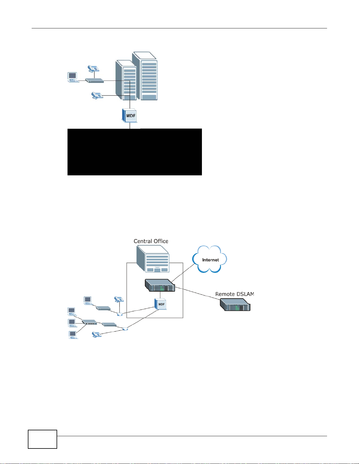
1.2.1 MTU Application
The following diagram depicts a typical application of the IES in a large residential building or
multiple tenant unit (MTU). This application leverages existing phone line wiring to provide voice
service and Internet access (with DSL modems) to all tenants. The MDF (Main Distribution Frame)
is the point of termination for the outside telephone company lines coming into a building and the
telephone wiring in the building. Note that xDSL service can co-exist with voice service on the same
line.
IES4005M User’s Guide 15
Chapter 1 System Introduction
Figure 1 Application: Multi-tenant Unit (MTU)
1.2.2 Central Office Application
The IES provides DSL and voice service over telephone wires to subscribers. The following figure
shows the IES setup in a telephone company’s central office.
Figure 2 Application: Central Office
16
IES4005M User’s Guide
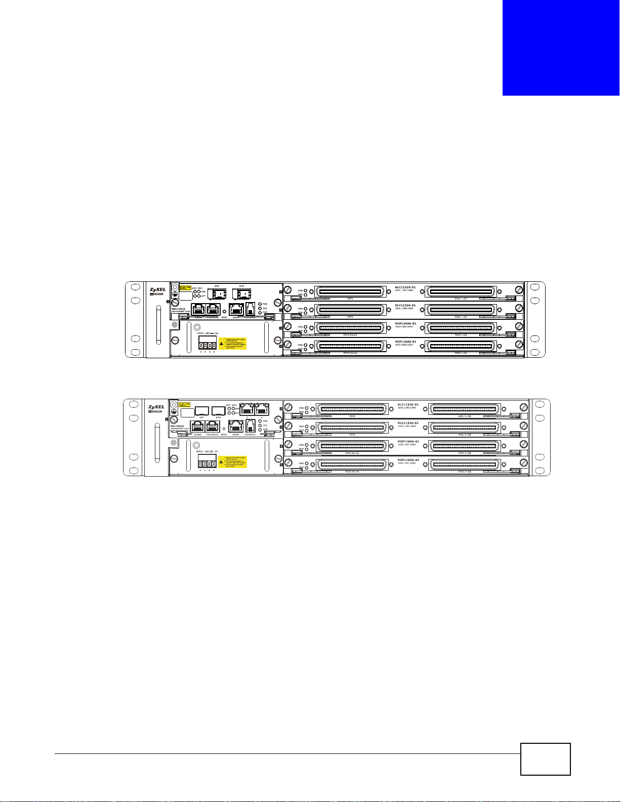
2.1 Appearance
The IES supports DC or AC power supply . The following figure shows the IES chassis with cards, the
MSC1002G/MSC1401G management card, and the IES4005M-DC installed. (If you need
information on the IES with AC power supply, refer to Chapter 4 on page 36.)
Figure 3 IES Front Panel with MSC1401G and IES4005M-DC
CHAPTER 2
IES Chassis
Figure 4 IES Front Panel with MSC1002G and IES4005M-DC
2.2 Deployment
Use mounting brackets to install the IES chassis in a 19-inch rack.
2.3 Bonding the IES
Caution!
All installation methods must be in accordance with national and local
regulations and practices.
Note: The IES is protected for overcurrent (short circuit) and overvoltage conditions.
IES4005M User’s Guide 17
Chapter 2 IES Chassis
#2 Phillips
M4
The unit is required to be bonded to a safety earth (ground) using a suitably rated cable:
• Cable gauge: 18 AWG minimum required (4 sq mm minimum suggested)
• Cable length: depends on the field environment. Use the shortest path to the ground.
• Type of cable terminal: gaug e 4~ 4.5 mm recommended
• Type of cable: sl ee ved
• Cable color: green and yellow required by safety
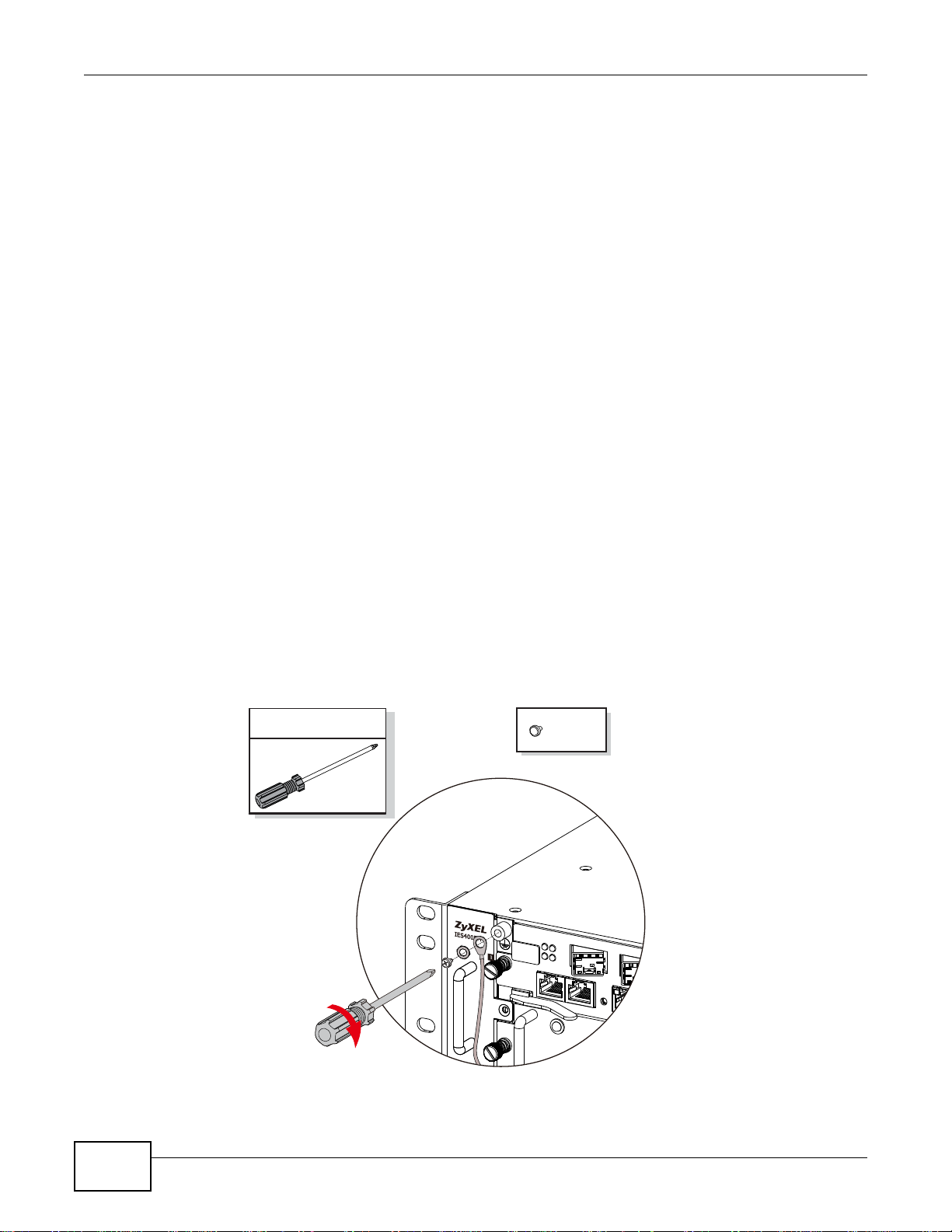
The cable must be attached to the IES using an M4 machine screw with a suitable lock washer. The
other end must be securely fastened to the chassis ground with a lug and screw arrangement of
M3.5 or greater. An example is shown in Figure 5 on page 18.
Warning!
Use caution when handling live electrical connections. Do not install
electrical equipment in wet or damp conditions. Do not allow anything to
rest on the power cable, and do not place the cable where people can
stand or walk on it. Verify that the IES is bonded before connecting
power.
• The frame ground is on the upper left of the chassis front panel.
• Connect the frame grounds to a building’s protective earthing terminals using a green-and-yellow
Figure 5 Bonding
frame ground wire.
Warning! Bond the frame ground before you connect any other cables or
wiring.
18
IES4005M User’s Guide

2.4 System Overview
The IES chassis, cards, and modules function together as follows:
• The management card transmits services upstream, receives downstream traffic into the IES,
and manages the system.
• Different management cards provide different upstream ports.
•The output power to the backplane which transmits the power to the fan module, line cards, and
management card.
• Subscriber devices connect to the IES line cards through subscriber cables, and to the IP network
through the management card.
• Different line cards provide different subscriber services (ALC1132G-51, VLC1132G-51, and
VOP1164G-61).
• Connect the public switched telephone network (PSTN/ISDN) or a VOP1164G-61’s port to the
POTS port on an xDSL line card to provide voice and DSL service to the line card’s subscribers.
• The management card connects to and monitors the fan module through the backplane.
Chapter 2 IES Chassis
IES4005M User’s Guide
19

Chapter 2 IES Chassis
20
IES4005M User’s Guide
CHAPTER 3
Management Cards
3.1 The MSC1401G Management Card
The MSC1401G aggregates the upstream service through optical PON connections and manages the
IES and the services of the line cards. The MSC1401G includes two SFP slots for single fiber GPON
interfaces with data rates of 1.244 Gbps upstream and 2.488 Gbps downstream. This card is hotswappable.
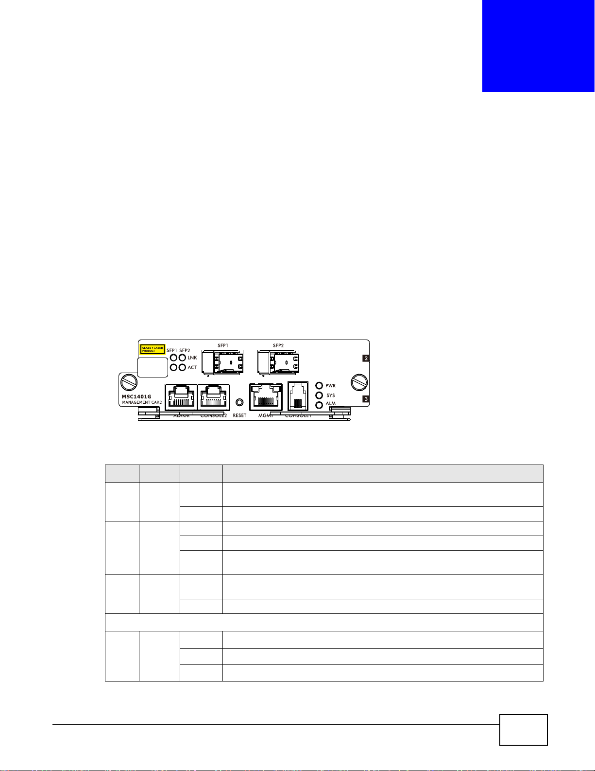
3.1.1 MSC1401G Front Panel
The following figure shows the front panel of the MSC1401G management card.
Figure 6 MSC1401G Front Panel
This table describes the front panel LEDs of the card.
Table 1 MSC1401G LED Descriptions
LED COLOR STATUS DESCRIPTION
PWR Green On The management switch card is installed and receiving power from the main
Off The management switch card is not receiving power from the main chassis.
SYS Green Blinking The system is initializing.
On The management switch card is on and functioning properly.
Off The management switch card is not receiving power, is not ready or has
ALM Red On An alarm has been detected on the IES. Examples of an alarm on the IES are
Off The IES has not detected an alarm on itself.
The following LEDs apply to the SFP slots.
LNK Green On The IES is ranged.
Blinking The IES is ranging.
Off There is no connection to the PON.
chassis.
malfunctioned.
when the IES’s voltage or temperature is outside of the normal range.
IES4005M User’s Guide 21
Chapter 3 Management Cards
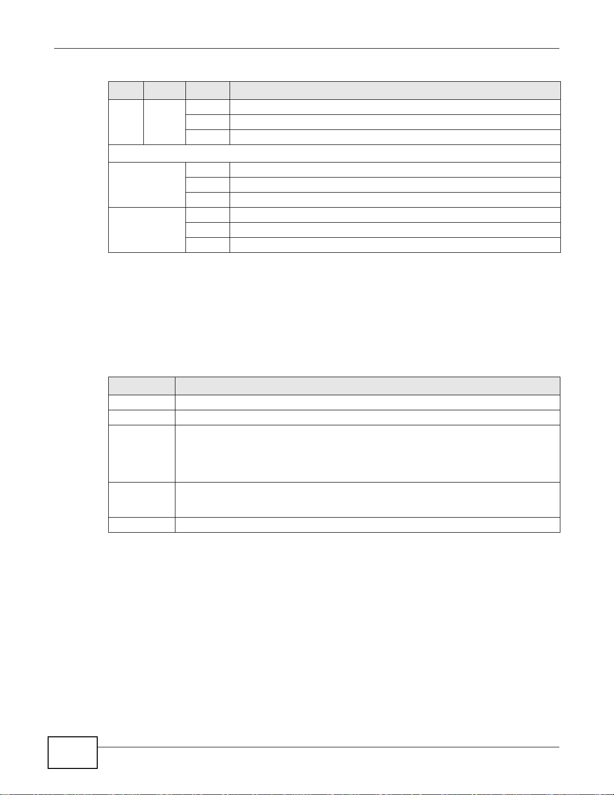
Table 1 MSC1401G LED Descriptions (continued)
LED COLOR STATUS DESCRIPTION
ACT Green On The IES is provisioned.
Blinking The IES is being provisioned.
Off The connection is idle.
The following LEDs apply to the Ethernet management port.
Green Blinking There is Ethernet traffic at 10 Mbps.
On A 10 Mbps Ethernet link is up.
Off The 10 Mbps Ethernet link is down.
Amber
Blinking There is Ethernet traffic at 100 Mbps.
On A 100 Mbps Ethernet link is up.
Off The 100 Mbps Ethernet link is down.
3.1.2 MSC1401G Ports
This table describes the ports on the MSC1401G.
Note: Install the management card before you make the hardware connections. See
Section 8.3.1 on page 61.
Table 2 MSC1401G Port Descriptions
LABEL DESCRIPTION
SFP1, SFP2 These PON interfaces consist of SFP transceiver slots for connecting to the IES.
ALARM This RJ-45 connector is for connecting to alarm output terminals on other equipment.
CONSOLE2 This RJ-45 RS-232 port is for connecting to a UPS. When you deploy the IES4005M with a
UPS, only the POTS modules function during a power outage so subscribers can still make
emergency calls.
Note: At the time of writing, the IES only complies with a Delta GES-R1K UPS.
MGMT This is an RJ-45 Ethernet port for connecting to an Ethernet network for out-of-band
management (a separate channel for management that is not part of the channels that are
usually used for data transfer).
CONSOLE1 This mini RJ-11 port is for connecting to a computer for local management.
3.1.3 GPON SFP Transceiver Specifications
See Chapter 7 on page 57 for the optical specifications of the supported optical transceivers.
3.1.4 MSC1401G Specifications
Note: The following table lists the MSC1401G’s specifications.
22
IES4005M User’s Guide
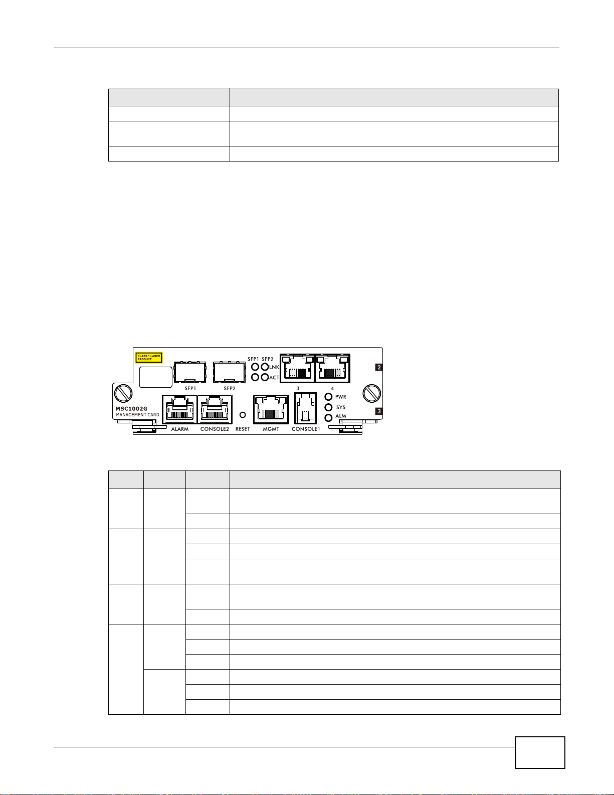
Table 3 MSC1401G Specifications
ITEM VALUE
Dimensions 130 mm (w) x 223 mm (D) x 42.4 mm (H)
Maximum Power
Consumption
Weight 516g
41.1Watts
3.2 The MSC1002G Management Card
The MSC1002G management card aggregates the upstream service through active-active Gigabit
Ethernet optical or electrical connections, manages the IES, and manages the services of the line
cards. This card is hot-swappable.
3.2.1 MSC1002G Front Panel
The following figure shows the front panel of the MSC1002G management card.
Chapter 3 Management Cards
Figure 7 MSC1002G Front Panel
This table describes the front panel LEDs of the card.
Table 4 Management Switch Card LED Descriptions
LED COLOR STATUS DESCRIPTION
PWR Green On The management switch card is installed and receiving power from the main
chassis.
Off The management switch card is not receiving power from the main chassis.
SYS Green Blinking The system is initializing.
On Th e management switch card is on and functioning properly.
Off The management switch card is not receiving power, is not ready or has
ALM Red On An alarm has been detected on the IES. Examples of an alarm on the IES are
Off The IES has not detected an alarm on itself.
MGMT Yellow Blinking The port is transmitting/receiving to/from a 100 Mbps Ethernet network.
On A 100 Mbps Ethernet link is up.
Off The Ethernet link is down.
Green Blinking The port is transmitting/receiving to/from a 10 Mbps Ethernet device.
On A 10 Mbps Ethernet link is up.
Off The Ethernet link is down.
malfunctioned.
when the IES’s voltage or temperature is outside of the normal range.
IES4005M User’s Guide
23
Chapter 3 Management Cards
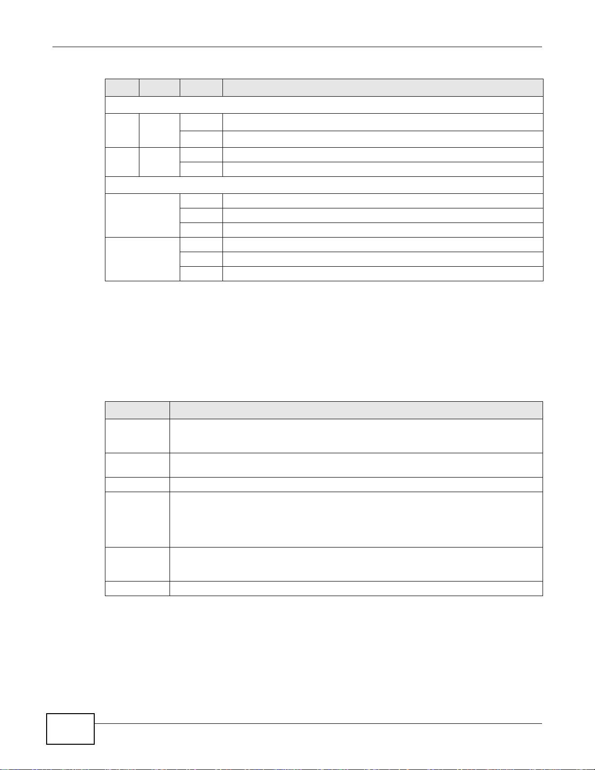
Table 4 Management Switch Card LED Descriptions (continued)
LED COLOR STATUS DESCRIPTION
The following LEDs apply to the SFP slots.
LNK Green On The optical Ethernet link is up.
Off There is no optical Ethernet link.
ACT Green Blinking There is optical Ethernet act ivity.
Off The connection is idle.
The following LEDs apply to the Gigabit Ethernet ports labeled 3 and 4.
Green Blinking There is Ethernet traffic at 1000 Mbps.
On A 1000 Mbps Ethernet link is up.
Off The 1000 Mbps Ethernet link is down.
Amber
Blinking There is Ethernet traffic at 10/100 Mbps.
On A 10/100 Mbps Ethernet link is up.
Off The 10/100 Mbps Ethernet link is down.
3.2.2 MSC1002G Ports
This table describes the ports on the MSC1002G.
Note: Install the management card before you make the hardware connections. See
Section 8.3.1 on page 61.
Table 5 Management Card Port Descriptions
LABEL DESCRIPTION
SFP1, SFP2 These are slots for SFP (Small Form Factor Pluggable) transceivers used to either connect to
the backbone network or do subtending. See Section 3.2.6.1 on page 26 for more
information.
3, 4 These RJ-45 Gigabit Ethernet ports are for connecting to a Gigabit Ethernet device that is part
ALARM This RJ-45 connector is for connecting to alarm output terminals on other equipment.
CONSOLE2 This RJ-45 RS-232 port is for connecting to a UPS. When you deploy the IES4005M with a
MGMT This is an RJ-45 Ethernet port for connecting to an Ethernet network for out-of-band
CONSOLE1 This mini RJ-11 port is for connecting to a computer for local management.
of a high-bandwidth backbone network or doing subtending.
UPS, only the POTS modules function during a power outage so subscribers can still make
emergency calls.
Note: At the time of writing, the IES only complies with a Delta GES-R1K UPS.
management (a separate channel for management that is not part of the channels that are
usually used for data transfer).
3.2.3 Alarm Connections
The IES ALARM connector is an RJ-45 female connector which provides 4 external alarm inputs for
normal close circuit, normal open circuit, and common dry contacts.
24
IES4005M User’s Guide
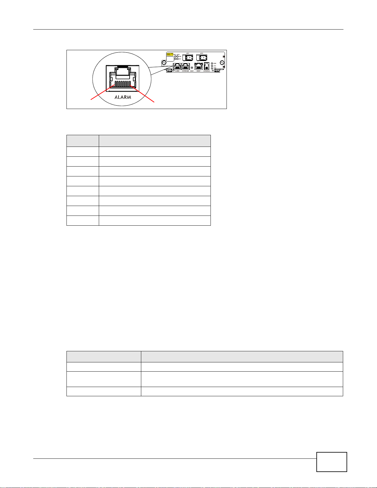
Figure 8 ALARM Connector PIN Layout
PIN1
PIN8
A closed circuit on the ALARM input pins indicates an alarm.
Table 6 Alarm Connector PIN Layout
PIN NO. NAME
1 Alarm input 1, normal close
2 Alarm input 1, common (FG)
3 Alarm input 2, normal close
4 Alarm input 3, normal close
5 Alarm input 3, common (FG)
6 Alarm input 2, common (FG)
7 Alarm input 4, normal close
8 Alarm input 4, common (FG)
Chapter 3 Management Cards
Short circuit: Alarm status is ON
Open circuit: Alarm status is OFF
Note: The alarm input is only for dry contact without any power.
The IES signals an alarm when it detects an alarm on the ALARM input pins, the IES4005M is
overheated, the voltage readings are outside the tolerance levels, a fan failed, or another alarm
occurs.
3.2.4 MSC1002G Specifications
Note: The following table lists the MSC1002G’s specifications.
Table 7 MSC1002G Specifications
ITEM VALUE
Dimensions 130 mm (w) x 223 mm (D) x 42.4 mm (H)
Maximum Power
Consumption
Weight 516g
37 Watts
3.2.5 Gigabit Ethernet SFP Transceiver Specifications
See Chapter 29 on page 221 for optical specifications of the supported optical transceivers.
IES4005M User’s Guide
25

Chapter 3 Management Cards
3.2.6 Gigabit Ethernet Interfaces
•Interface SFP1 and port 3 are a Gigabit Ethernet port/SFP slot pair.
•Interface SFP2 and port 4 are a Gigabit Ethernet port/SFP slot pair.
The SFP slots have priority over the Gigabit Ethernet (GE) ports. This means that if a SFP
transceiver and the corresponding GE port are connected at the same time, the GE port will be
disabled.
To avoid possible eye injury, do not look into an operating fiber-optic
module’s connectors.
The Ethernet ports are auto-negotiating and can detect and adjust to the optimum Ethernet speed
(100/1000 Mbps) and duplex mode (full duplex or half duplex) of the connected device. The
Ethernet ports are also auto-crossover (auto-MDI/MDI-X), they automatically work with a straightthrough or crossover Ethernet cable.
3.2.6.1 Uplink and Subtending
The Gigabit Ethernet SFP slots and ports can function in either subtending or uplink mode. Connect
a port in uplink mode to an backbone Ethernet switch or router. The management switch card
allows traffic between the ports in uplink mode and the DSL ports on the line cards.
Use the subtending mode to daisy-chain other Ethernet switches. With subtending mode, the
management switch card allows traffic between the ports in subtending mode and the ports in
uplink mode. The management switch card does not allow traffic between the ports in subtending
mode and the DSL ports on the line cards.
3.2.6.2 SFP Slots
These are slots for SFP transceivers. A transceiver is a single unit that houses a transmitter and a
receiver. The switch does not come with transceivers.
You must use SFP tr ansceivers that comply with the SFP Transceiver MultiSource Agreement (MSA).
See the SFF committee’s INF-8074i specification Rev 1.0 for details.
• Type: SFP connection interface
• Connection speed: 1 Gigabit per second (Gbps)
You can change transceivers while the IES is operating. You can use different transceivers to
connect to Ethernet switches with different types of fiber-optic connectors.
3.2.6.3 Transceiver Installation
Use the following steps to install a mini GBIC transceiver (SFP module) in a slot.
1 Remove the dust cover from the transceiver.
2 For transceivers with a flip-up or flip-down latch, close the latch.
3 Insert the fiber-optic cables into the transceiver (you may need to remove cable dust covers).
4 Insert the transceiver into the slot with the exposed section of PCB board facing down.
26
IES4005M User’s Guide
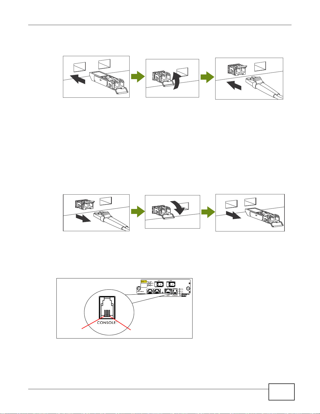
5 Press the transceiver firmly until it clicks into place.
PIN1
PIN4
Figure 9 Installing a Transceiver
3.2.6.4 Transceiver Removal
Use the following steps to remove a mini GBIC transceiver (SFP module) from the slot.
1 Remove the fiber-optic cables from the transceiver.
2 Unlock the transceiver’s latch (latch styles vary).
3 Pull the transceiver out of the slot.
Chapter 3 Management Cards
4 Put the transceiver’s dust cover on the transceiver.
Figure 10 Removing a Transceiver
3.2.7 CONSOLE1 Port Pin Assignment
Use this mini RJ-11 port for local management of the IES.
Figure 11 CONSOLE1 Mini RJ-11 Female Connector
IES4005M User’s Guide
27

Chapter 3 Management Cards
PIN1
PIN8
Table 8 CONSOLE1 Port PIN Layout
PIN NO. NAME
1NC
2WA3-TX
3WA3-RX
4GND
3.2.8 CONSOLE2 Port Pin Assignment
Use this RJ-45 port for connecting to a UPS.
Figure 12 CONSOLE2 RJ-45 Female Connector
Table 9 CONSOLE2 Port PIN Layout
PIN NO. NAME NOTE
1 DTR RS-232 for UPS
2 CTS RS-232 for UPS
3RXD-PON
4GND
5 RXD-UPS RS-232 for UPS
6 TXD-UPS RS-232 for UPS
7TXD-PON
8 RTS RS-232 for UPS
28
IES4005M User’s Guide
CHAPTER 4
LEDs
4.1 Line Cards and the Chassis Slots
The following table describes the IES slots, cards, and modules.
Table 10 Slots and Cards
SLOT TYPE
Fan IES4005M-FAN Controls and monitors the fans. This module is hot-
Power IES4005M-AC Converts AC input into +14.5VDC and -54VDC. 1
Line Card ALC1132G-51 Provides ADSL2+ 32-line connection for broadband data
MODULE OR
CARD NAME
IES4005M-DC Converts -48 VDC input into +14.5VDC.
VLC1132G-51 Provides VDSL2 32-line connection for broadband data
VOP1164G-61 Provides POTS 64-line connection for VoIP services. This
FUNCTION
swappable.
services. This card is hot-swappable.
services and IPTV applications. This card is hot-swappable.
card is hot-swappable.
Line Cards
NUMBER
OF SLOTS
1
4
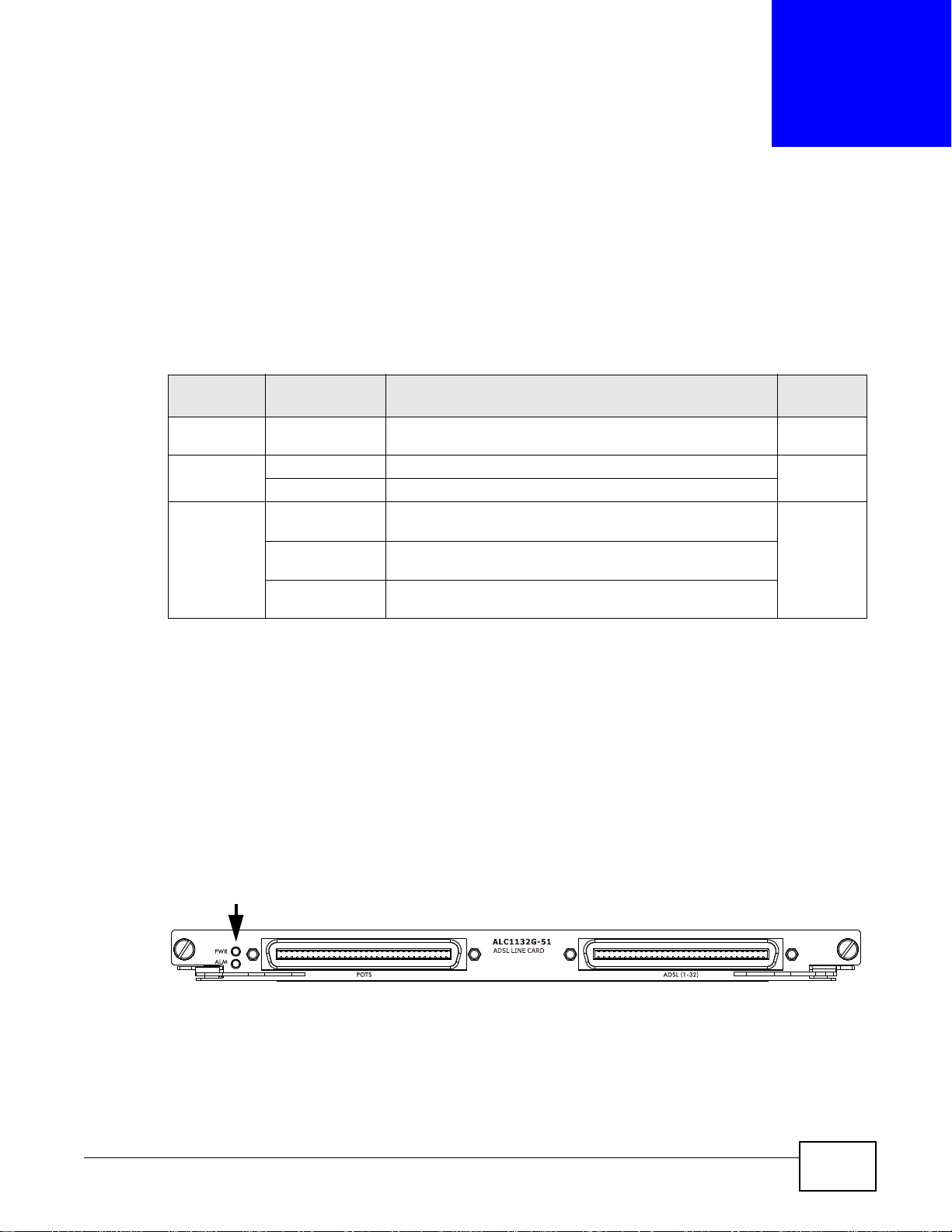
4.2 ADSL Line Card
The ALC1132G-51 card provides up to 32 ADSL2+ lines for data and IPTV services and includes
internal splitters. This card is hot-swappable.
4.2.1 Front Panel
The following figure shows the front panel of ALC1132G-51.
Figure 13 ALC1132G-51’s Front Panel
IES4005M User’s Guide 29

Chapter 4 Line Cards
This table describes the front panel LEDs of ALC1132G-51.
Table 11 ALC1132G-51 LED Descriptions
LED COLOR STATUS DESCRIPTION
PWR Green On The line card is turned on.
ALM Red On The line card has a critical alarm.
4.2.2 Ports
This table describes the ports on ALC1132G-51’s front panel.
Table 12 ALC1132G-51 Port Descriptions
LABEL DESCRIPTION
ADSL(1-32) One 32-line data and voice port with Telco 64 connector
POTS One 32-line POTS port with Telco 64 connector
Off The line card is turned off or has failed.
Off The line card is operating normally.
4.2.3 Pin Assignments
The line card Telco 64 connectors (also known as Champ 64) are female. The following figure and
table describe the pinouts of the Telco 64 connectors.
30
IES4005M User’s Guide
 Loading...