

Page 1

Ethernet Switch
CLI Reference Guide
Version 3.80
9/2007
Edition 1
DEFAULT LOGIN
In-band IP Address http://192.168.1.1
Out-of-band IP Address http://192.168.0.1
User Name admin
Password 1234
www.zyxel.com
Page 2

Page 3

About This CLI Reference Guide
About This CLI Reference Guide
Intended Audience
This manual is intended for people who want to configure ZyXEL Switches via Command
Line Interface (CLI). You should have at least a basic knowledge of TCP/IP networking
concepts and topology.
" This guide is intended as a command reference for a series of products.
Therefore many commands in this guide may not be available in your product.
See your User’s Guide for a list of supported features and details about feature
implementation.
Please refer to www.zyxel.com or your product’s CD for product specific User Guides and
product certifications.
How To Use This Guide
•Read the How to Access the CLI chapter for an overview of various ways you can get to
the command interface on your Switch.
• Use the Reference section in this guide for command syntax, description and examples.
Each chapter describes commands related to a feature.
• To find specific information in this guide, use the Contents Overview, the Index of
Commands, or search the PDF file. E-mail techwriters@zyxel.com.tw if you cannot find
the information you require.
CLI Reference Guide Feedback
Help us help you. Send all Reference Guide-related comments, questions or suggestions for
improvement to the following address, or use e-mail instead. Thank you!
The Technical Writing Team,
ZyXEL Communications Corp.,
6 Innovation Road II,
Science-Based Industrial Park,
Hsinchu, 300, Taiwan.
E-mail: techwriters@zyxel.com.tw
Ethernet Switch CLI Reference Guide
3
Page 4

Document Conventions
Document Conventions
Warnings and Notes
These are how warnings and notes are shown in this CLI Reference Guide.
1 Warnings tell you about things that could harm you or your device. See your
User’s Guide for product specific warnings.
" Notes tell you other important information (for example, other things you may
need to configure or helpful tips) or recommendations.
Syntax Conventions
This manual follows these general conventions:
• ZyXEL’s switches (such as the ES-2024A, ES-2108, GS-3012, and so on) may be referred
to as the “Switch”, the “device”, the “system” or the “product” in this Reference Guide.
• Units of measurement may denote the “metric” value or the “scientific” value. For
example, “k” for kilo may denote “1000” or “1024”, “M” for mega may denote “1000000”
or “1048576” and so on.
Command descriptions follow these conventions:
• Commands are in
• Required input values are in angle brackets <>; for example,
must specify an IP address for this command.
• Optional fields are in square brackets []; for instance show logins [name], the name
field is optional.
The following is an example of a required field within an optional field: snmp-server
[contact <system contact>], the contact field is optional. However, if you
use contact, then you must provide the system contact information.
• Lists (such as <port-list>) consist of one or more elements separated by commas.
Each element might be a single value (1, 2, 3, ...) or a range of values (1-2, 3-5, ...)
separated by a dash.
•The | (bar) symbol means “or”.
• italic terms represent user-defined input values; for example, in snmp-server
[contact <system contact>], system contact can be replaced by the
administrator’s name.
• A key stroke is denoted by square brackets and uppercase text, for example, [ENTER]
means the “Enter” or “Return” key on your keyboard.
courier new font.
ping <ip> means that you
4
Ethernet Switch CLI Reference Guide
Page 5
Document Conventions
• <cr> means press the [ENTER] key.
• An arrow (-->) indicates that this line is a continuation of the previous line.
Command summary tables are organized as follows:
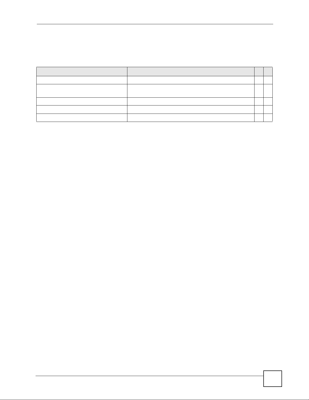
Table 1 Example: Command Summary Table
COMMAND DESCRIPTION M P
show vlan Displays the status of all VLANs. E 3
vlan <1-4094> Enters config-vlan mode for the specified VLAN. Creates the
VLAN, if necessary.
inactive Disables the specified VLAN. C 13
no inactive Enables the specified VLAN. C 13
no vlan <1-4094> Deletes a VLAN. C 13
C13
The Table title identifies commands or the specific feature that the commands configure.
The COMMAND column shows the syntax of the command.
• If a command is not indented, you run it in the enable or config mode. See Chapter 2 on
page 15 for more information on command modes.
• If a command is indented, you run it in a sub-command mode.
The DESCRIPTION column explains what the command does. It also identifies legal input
values, if necessary.
The M column identifies the mode in which you run the command.
• E: The command is available in enable mode. It is also available in user mode if the
privilege level (P) is less than 13.
• C: The command is available in config (not indented) or one of the sub-command modes
(indented).
The P column identifies the privilege level of the command. If you don’t have a high enough
privilege level you may not be able to view or execute some of the commands. See Chapter 2
on page 15 for more information on privilege levels.
Ethernet Switch CLI Reference Guide
5
Page 6
Document Conventions
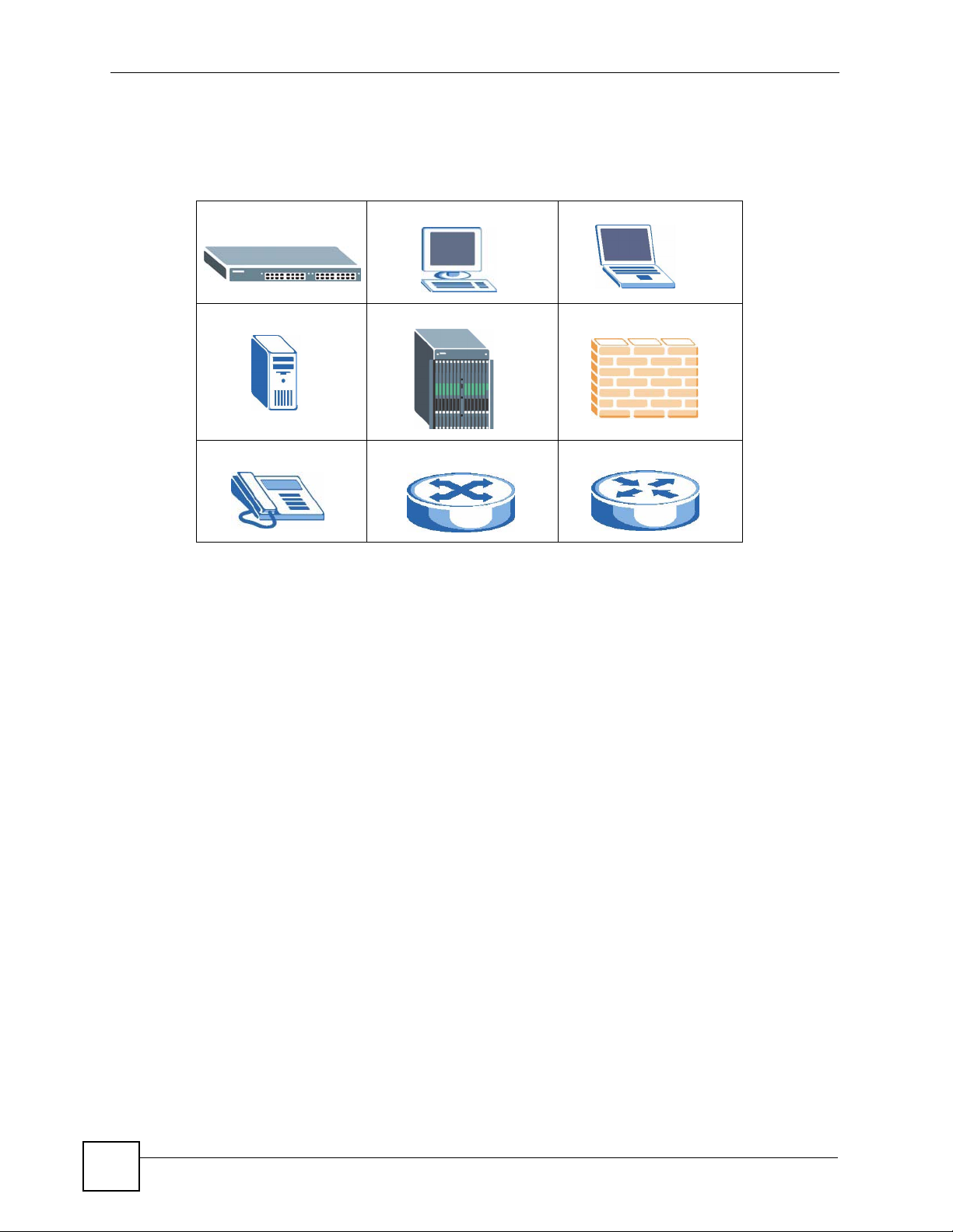
Icons Used in Figures
Figures in this guide may use the following generic icons. The Switch icon is not an exact
representation of your device.
Switch Computer Notebook computer
Server DSLAM Firewall
Telephone Switch Router
6
Ethernet Switch CLI Reference Guide
Page 7

Contents Overview
Contents Overview
Introduction .............................................................................................................................. 9
How to Access and Use the CLI .................................................................................................11
Privilege Level and Command Mode ......................................................................................... 15
Initial Setup ................................................................................................................................ 21
Reference A-G ........................................................................................................................25
AAA Commands ........................................................................................................................ 27
ARP Commands ........................................................................................................................ 29
ARP Inspection Commands ...................................................................................................... 31
Bandwidth Commands .............................................................................................................. 37
Broadcast Storm Commands ..................................................................................................... 41
Classifier Commands ................................................................................................................ 45
Cluster Commands .................................................................................................................... 49
Date and Time Commands ........................................................................................................ 53
DHCP Commands ..................................................................................................................... 57
DHCP Snooping & DHCP VLAN Commands ............................................................................ 63
DiffServ Commands ................................................................................................................... 67
DVMRP Commands .................................................................................................................. 69
Ethernet OAM Commands ........................................................................................................ 71
GARP Commands ..................................................................................................................... 77
GVRP Commands ..................................................................................................................... 79
Reference H-M ........................................................................................................................81
HTTPS Server Commands ........................................................................................................ 83
IEEE 802.1x Authentication Commands ................................................................................... 87
IGMP and Multicasting Commands ........................................................................................... 89
IGMP Snooping Commands ...................................................................................................... 91
IGMP Filtering Commands ........................................................................................................95
Interface Commands ................................................................................................................. 97
Interface Route-domain Mode ................................................................................................. 101
IP Commands .......................................................................................................................... 103
IP Source Binding Commands ................................................................................................ 107
Logging Commands ................................................................................................................ 109
Login Account Commands .......................................................................................................111
Loopguard Commands .............................................................................................................113
MAC Address Commands ........................................................................................................115
MAC Authentication Commands ..............................................................................................117
Ethernet Switch CLI Reference Guide
7
Page 8

Contents Overview
MAC Filter Commands .............................................................................................................119
MAC Forward Commands ....................................................................................................... 121
Mirror Commands .................................................................................................................... 123
MRSTP Commands .................................................................................................................125
MSTP Commands ................................................................................................................... 127
Multiple Login Commands ....................................................................................................... 131
MVR Commands ..................................................................................................................... 133
Reference N-S ......................................................................................................................135
OSPF Commands ................................................................................................................... 137
Password Commands ............................................................................................................. 141
PoE Commands ...................................................................................................................... 143
Policy Commands .................................................................................................................... 147
Port Security Commands .........................................................................................................151
Port-based VLAN Commands ................................................................................................. 153
Protocol-based VLAN Commands ........................................................................................... 155
Queuing Commands ................................................................................................................ 157
RADIUS Commands ................................................................................................................161
Remote Management Commands ........................................................................................... 163
RIP Commands ....................................................................................................................... 165
Running Configuration Commands ......................................................................................... 167
SNMP Server Commands ....................................................................................................... 169
STP and RSTP Commands ..................................................................................................... 173
SSH Commands ...................................................................................................................... 177
Static Route Commands ..........................................................................................................179
Subnet-based VLAN Commands ............................................................................................ 183
Syslog Commands .................................................................................................................. 185
Reference T-Z .......................................................................................................................187
TACACS+ Commands ............................................................................................................. 189
TFTP Commands .................................................................................................................... 191
Trunk Commands .................................................................................................................... 193
trTCM Commands ................................................................................................................... 197
VLAN Commands .................................................................................................................... 199
VLAN IP Commands ...............................................................................................................203
VLAN Port Isolation Commands .............................................................................................. 205
VLAN Stacking Commands ..................................................................................................... 207
VLAN Trunking Commands ..................................................................................................... 209
VRRP Commands ....................................................................................................................211
Additional Commands ............................................................................................................. 215
Appendices and Index of Commands ................................................................................ 223
8
Ethernet Switch CLI Reference Guide
Page 9

PART I
Introduction
How to Access and Use the CLI (11)
Privilege Level and Command Mode (15)
Initial Setup (21)
9
Page 10

10
Page 11

CHAPTER 1
How to Access and Use the CLI
This chapter introduces the command line interface (CLI).
1.1 Accessing the CLI
Use any of the following methods to access the CLI.
1.1.1 Console Port
1 Connect your computer to the console port on the Switch using the appropriate cable.
2 Use terminal emulation software with the following settings:
Table 2 Default Settings for the Console Port
SETTING DEFAULT VALUE
Terminal Emulation VT100
Baud Rate 9600 bps
Parity None
Number of Data Bits 8
Number of Stop Bits 1
Flow Control None
3 Press [ENTER] to open the login screen.
1.1.2 Telnet
1 Connect your computer to one of the Ethernet ports.
2 Open a Telnet session to the Switch’s IP address. If this is your first login, use the default
values.
Table 3 Default Management IP Address
SETTING DEFAULT VALUE
IP Address 192.168.1.1
Subnet Mask 255.255.255.0
Make sure your computer IP address is in the same subnet, unless you are accessing the
Switch through one or more routers.
Ethernet Switch CLI Reference Guide
11
Page 12

Chapter 1 How to Access and Use the CLI
1.1.3 SSH
1 Connect your computer to one of the Ethernet ports.
2 Use a SSH client program to access the Switch. If this is your first login, use the default
values in Table 3 on page 11 and Table 4 on page 12. Make sure your computer IP
address is in the same subnet, unless you are accessing the Switch through one or more
routers.
1.2 Logging in
Use the administrator username and password. If this is your first login, use the default values.
Table 4 Default User Name and Password
SETTING DEFAULT VALUE
User Name admin
Password 1234
" The Switch automatically logs you out of the management interface after five
minutes of inactivity. If this happens to you, simply log back in again.
1.3 Using Shortcuts and Getting Help
This table identifies some shortcuts in the CLI, as well as how to get help.
Table 5 CLI Shortcuts and Help
COMMAND / KEY(S) DESCRIPTION
history Displays a list of recently-used commands.
yz (up/down arrow keys) Scrolls through the list of recently-used commands. You can edit
[CTRL]+U Clears the current command.
[TAB] Auto-completes the keyword you are typing if possible. For
? Displays the keywords and/or input values that are allowed in
help Displays the (full) commands that are allowed in place of help.
any command or press [ENTER] to run it again.
example, type config, and press [TAB]. The Switch finishes the
word configure.
place of the ?.
12
Ethernet Switch CLI Reference Guide
Page 13

Chapter 1 How to Access and Use the CLI
1.4 Saving Your Configuration
When you run a command, the Switch saves any changes to its run-time memory. The Switch
loses these changes if it is turned off or loses power. Use the
enable mode to save the current configuration permanently to non-volatile memory.
sysname# write memory
write memory command in
" You should save your changes after each CLI session. All unsaved
configuration changes are lost once you restart the Switch.
1.5 Logging Out
Enter logout to log out of the CLI. You have to be in user, enable, or config mode. See
Chapter 2 on page 15 for more information about modes.
Ethernet Switch CLI Reference Guide
13
Page 14

Chapter 1 How to Access and Use the CLI
14
Ethernet Switch CLI Reference Guide
Page 15

CHAPTER 2
Privilege Level and Command
Mode
This chapter introduces the CLI privilege levels and command modes.
• The privilege level determines whether or not a user can run a particular command.
• If a user can run a particular command, the user has to run it in the correct mode.
2.1 Privilege Levels
Every command has a privilege level (0-14). Users can run a command if the session’s
privilege level is greater than or equal to the command’s privilege level. The session’s
privilege level initially comes from the login account’s privilege level, though it is possible to
change the session’s privilege level after logging in.
2.1.1 Privilege Levels for Commands
The privilege level of each command is listed in the Reference A-G chapters on page 25.
At the time of writing, commands have a privilege level of 0, 3, 13, or 14. The following table
summarizes the types of commands at each of these privilege levels.
Table 6 Types of Commands at Different Privilege Levels
PRIVILEGE LEVEL TYPES OF COMMANDS AT THIS PRIVILEGE LEVEL
0 Display basic system information.
3 Display configuration or status.
13 Configure features except for login accounts, the authentication method
sequence, multiple logins, and administrator and enable passwords.
14 Configure login accounts, the authentication method sequence, multiple logins,
and administrator and enable passwords.
2.1.2 Privilege Levels for Login Accounts
You can manage the privilege levels for login accounts in the following ways:
• Using commands. Login accounts can be configured by the admin account or any login
account with a privilege level of 14. See Chapter 29 on page 111.
• Using vendor-specific attributes in an external authentication server. See the User’s Guide
for more information.
Ethernet Switch CLI Reference Guide
15
Page 16

Chapter 2 Privilege Level and Command Mode
The admin account has a privilege level of 14, so the administrator can run every command.
You cannot change the privilege level of the admin account.
2.1.3 Privilege Levels for Sessions
The session’s privilege level initially comes from the privilege level of the login account the
user used to log in to the Switch. After logging in, the user can use the following commands to
change the session’s privilege level.
2.1.3.1 enable Command
This command raises the session’s privilege level to 14. It also changes the session to enable
mode (if not already in enable mode). This command is available in user mode or enable
mode, and users have to know the enable password.
In the following example, the login account user0 has a privilege level of 0 but knows that the
enable password is 123456. Afterwards, the session’s privilege level is 14, instead of 0, and
the session changes to enable mode.
sysname> enable
Password: 123456
sysname#
The default enable password is 1234. Use this command to set the enable password.
password <password>
<password> consists of 1-32 alphanumeric characters. For example, the following
command sets the enable password to 123456. See Chapter 68 on page 215 for more
information about this command.
sysname(config)# password 123456
2.1.3.2 enable <0-14> Command
This command raises the session’s privilege level to the specified level. It also changes the
session to enable mode, if the specified level is 13 or 14. This command is available in user
mode or enable mode, and users have to know the password for the specified privilege level.
In the following example, the login account user0 has a privilege level of 0 but knows that the
password for privilege level 13 is pswd13. Afterwards, the session’s privilege level is 13,
instead of 0, and the session changes to enable mode.
sysname> enable 13
Password: pswd13
sysname#
16
Users cannot use this command until you create passwords for specific privilege levels. Use
the following command to create passwords for specific privilege levels.
password <password> privilege <0-14>
Ethernet Switch CLI Reference Guide
Page 17

Chapter 2 Privilege Level and Command Mode
<password> consists of 1-32 alphanumeric characters. For example, the following
command sets the password for privilege level 13 to pswd13. See Chapter 68 on page 215 for
more information about this command.
sysname(config)# password pswd13 privilege 13
2.1.3.3 disable Command
This command reduces the session’s privilege level to 0. It also changes the session to user
mode. This command is available in enable mode.
2.2 Command Modes
The CLI is divided into several modes. If a user has enough privilege to run a particular
command, the user has to run the command in the correct mode. The modes that are available
depend on the session’s privilege level.
2.2.1 Command Modes for Privilege Levels 0-12
If the session’s privilege level is 0-12, the user and all of the allowed commands are in user
mode. Users do not have to change modes to run any allowed commands.
2.2.2 Command Modes for Privilege Levels 13-14
If the session’s privilege level is 13-14, the allowed commands are in one of several modes.
Table 7 Command Modes for Privilege Levels 13-14 and the Types of Commands in Each One
MODE PROMPT COMMAND FUNCTIONS IN THIS MODE
enable sysname# Display current configuration, diagnostics, maintenance.
config sysname(config)# Configure features other than those below.
config-interface sysname(config-interface)# Configure ports.
config-interface sysname(config-interface)# Configure ports.
config-mvr sysname(config-mvr)# Configure multicast VLAN.
config-routedomain
config-dvmrp sysname(config-dvmrp)# Configure Distance Vector Multicast Routing Protocol
config-igmp sysname(config-igmp)# Configure Internet Group Management Protocol (IGMP).
config-ospf sysname(config-ospf)# Configure Open Shortest Path First (OSPF) protocol.
config-rip sysname(config-rip)# Configure Routing Information Protocol (RIP).
config-vrrp sysname(config-vrrp)# Configure Virtual Router Redundancy Protocol (VRRP).
sysname(config-if)# Enable and enter configuration mode for an IP routing
domain.
(DVRMP).
Ethernet Switch CLI Reference Guide
17
Page 18

Chapter 2 Privilege Level and Command Mode
Each command is usually in one and only one mode. If a user wants to run a particular
command, the user has to change to the appropriate mode. The command modes are organized
like a tree, and users start in enable mode. The following table explains how to change from
one mode to another.
Table 8 Changing Between Command Modes for Privilege Levels 13-14
MODE ENTER MODE LEAVE MODE
enable -- --
config configure exit
config-interface interface port-channel <port-list> exit
config-mvr mvr <1-4094> exit
config-vlan vlan <1-4094> exit
config-route-domain interface route domain <ip-address>/<mask-bits> exit
config-dvmrp router dvmrp exit
config-igmp router igmp exit
config-ospf router ospf <router-id> exit
config-rip router rip exit
config-vrrp router vrrp network <ip-address>/<mask-bits>
vr-id <1~7> uplink-gateway <ip-address>
exit
2.3 Listing Available Commands
Use the help command to view the executable commands on the Switch. You must have the
highest privilege level in order to view all the commands. Follow these steps to create a list of
supported commands:
1 Log into the CLI. This takes you to the enable mode.
2 Type help and press [ENTER]. A list comes up which shows all the commands
available in enable mode. The example shown next has been edited for brevity’s sake.
sysname# help
Commands available:
help
logout
exit
history
enable <0-14>
enable <cr> traceroute <ip|host-name> [vlan <vlan-id>][..]
.
.
traceroute help
ssh <1|2> <[user@]dest-ip> <cr>
ssh <1|2> <[user@]dest-ip> [command </>]
sysname#
18
Ethernet Switch CLI Reference Guide
Page 19

Chapter 2 Privilege Level and Command Mode
3 Copy and paste the results into a text editor of your choice. This creates a list of all the
executable commands in the user and enable modes.
4 Type configure and press [ENTER]. This takes you to the config mode.
5 Type help and press [ENTER]. A list is displayed which shows all the commands
available in config mode and all the sub-commands. The sub-commands are preceded by
the command necessary to enter that sub-command mode. For example, the command
name <name-str> as shown next, is preceded by the command used to enter the
config-vlan sub-mode:
sysname# help
.
.
no arp inspection log-buffer logs
no arp inspection filter-aging-time
no arp inspection <cr>
vlan <1-4094>
vlan <1-4094> name <name-str>
vlan <1-4094> normal <port-list>
vlan <1-4094> fixed <port-list>
vlan <1-4094>.
6 Copy and paste the results into a text editor of your choice. This creates a list of all the
executable commands in config and the other submodes, for example, the config-vlan
mode.
Ethernet Switch CLI Reference Guide
19
Page 20

Chapter 2 Privilege Level and Command Mode
20
Ethernet Switch CLI Reference Guide
Page 21

CHAPTER 3
Initial Setup
This chapter identifies tasks you might want to do when you first configure the Switch.
3.1 Changing the Administrator Password
" It is recommended you change the default administrator password.
Use this command to change the administrator password.
admin-password <pw-string> <Confirm-string>
where <pw-string> may be 1-32 alphanumeric characters long.
sysname# configure
sysname(config)# admin-password t1g2y7i9 t1g2y7i9
3.2 Changing the Enable Password
" It is recommended you change the default enable password.
Use this command to change the enable password.
password <password>
where <password> may be 1-32 alphanumeric characters long.
sysname# configure
sysname(config)# password k8s8s3dl0
Ethernet Switch CLI Reference Guide
21
Page 22

Chapter 3 Initial Setup
3.3 Prohibiting Concurrent Logins
By default, multiple CLI sessions are allowed via the console port or Telnet. See the User’s
Guide for the maximum number of concurrent sessions for your Switch. Use this command to
prohibit concurrent logins.
no multi-login
Console port has higher priority than Telnet. See Chapter 38 on page 131 for more multi-
login
commands.
sysname# configure
sysname(config)# no multi-login
3.4 Changing the Management IP Address
The Switch has a different IP address in each VLAN. By default, the Switch has VLAN 1 with
IP address 192.168.1.1 and subnet mask 255.255.255.0. Use this command in config-vlan
mode to change the management IP address in a specific VLAN.
ip address <ip> <mask>
This example shows you how to change the management IP address in VLAN 1 to 172.16.0.1
with subnet mask 255.255.255.0.
sysname# configure
sysname(config)# vlan 1
sysname(config-vlan)# ip address 172.16.0.1 255.255.255.0
" Afterwards, you have to use the new IP address to access the Switch.
3.5 Changing the Out-of-band Management IP Address
If your Switch has a MGMT port (also referred to as the out-of-band management port), then
the Switch can also be managed via this interface. By default, the MGMT port IP address is
192.168.0.1 and the subnet mask is 255.255.255.0. Use this command in config mode to
change the out-of-band management IP address.
ip address <ip> <mask>
This example shows you how to change the out-of-band management IP address to 10.10.10.1
with subnet mask 255.255.255.0 and the default gateway 10.10.10.254
22
sysname# configure
sysname(config)# ip address 10.10.10.1 255.255.255.0
sysname(config)# ip address default-gateway 10.10.10.254
Ethernet Switch CLI Reference Guide
Page 23

3.6 Looking at Basic System Information
Use this command to look at general system information about the Switch.
show system-information
This is illustrated in the following example.
sysname# show system-information
System Name : sysname
System Contact :
System Location :
Ethernet Address : 00:13:49:ae:fb:7a
ZyNOS F/W Version : V3.80(AII.0)b0 | 04/18/2007
RomRasSize : 1746416
System up Time : 280:32:52 (605186d ticks)
Bootbase Version : V1.00 | 05/17/2006
ZyNOS CODE : RAS Apr 18 2007 19:59:49
Product Model : ES-2024PWR
Chapter 3 Initial Setup
See Chapter 68 on page 215 for more information about these attributes.
3.7 Looking at the Operating Configuration
Use this command to look at the current operating configuration.
show running-config
This is illustrated in the following example.
sysname# show running-config
Building configuration...
Current configuration:
vlan 1
name 1
normal ""
fixed 1-9
forbidden ""
untagged 1-9
ip address default-management 172.16.37.206 255.255.255.0
ip address default-gateway 172.16.37.254
exit
Ethernet Switch CLI Reference Guide
23
Page 24

Chapter 3 Initial Setup
24
Ethernet Switch CLI Reference Guide
Page 25

PART II
Reference A-G
AAA Commands (27)
ARP Commands (29)
ARP Inspection Commands (31)
Bandwidth Commands (37)
Broadcast Storm Commands (41)
Classifier Commands (45)
Cluster Commands (49)
Date and Time Commands (53)
DHCP Commands (57)
DHCP Snooping & DHCP VLAN Commands (63)
DiffServ Commands (67)
DVMRP Commands (69)
Ethernet OAM Commands (71)
GARP Commands (77)
GVRP Commands (79)
25
Page 26

26
Page 27

CHAPTER 4
AAA Commands
Use these commands to configure authentication and accounting on the Switch.
4.1 Command Summary
The following section lists the commands for this feature.
Table 9 aaa authentication Command Summary
COMMAND DESCRIPTION M P
show aaa authentication Displays what methods are used for authentication. E 3
show aaa authentication enable Displays the authentication method(s) for checking privilege
level of administrators.
aaa authentication enable
<method1> [<method2> ...]
no aaa authentication enable Resets the method list for checking privileges to its default
show aaa authentication login Displays the authentication methods for administrator login
aaa authentication login
<method1> [<method2> ...]
no aaa authentication login Resets the method list for the authentication of login accounts
Specifies which method should be used first, second, and
third for checking privileges.
method: enable, radius, or tacacs+.
value.
accounts.
Specifies which method should be used first, second, and
third for the authentication of login accounts.
method: local, radius, or tacacs+.
to its default value.
E3
C14
C14
E3
C14
C14
Table 10 Command Summary: aaa accounting
COMMAND DESCRIPTION M P
show aaa accounting Displays accounting settings configured on the Switch. E 3
show aaa accounting update Display the update period setting on the Switch for
accounting sessions.
aaa accounting update periodic
<1-2147483647>
no aaa accounting update Resets the accounting update interval to the default value. C 13
show aaa accounting commands Displays accounting settings for recording command events. E 3
aaa accounting commands
<privilege> stop-only tacacs+
[broadcast]
Ethernet Switch CLI Reference Guide
Sets the update period (in minutes) for accounting sessions.
This is the time the Switch waits to send an update to an
accounting server after a session starts.
Enables accounting of command sessions and specifies the
minimum privilege level (0-14) for the command sessions that
should be recorded. Optionally, sends accounting information
for command sessions to all configured accounting servers at
the same time.
E3
C13
C13
27
Page 28

Chapter 4 AAA Commands
Table 10 Command Summary: aaa accounting (continued)
COMMAND DESCRIPTION M P
no aaa accounting commands Disables accounting of command sessions on the Switch. C 13
show aaa accounting dot1x Displays accounting settings for recording IEEE 802.1x
aaa accounting dot1x <startstop|stop-only>
<radius|tacacs+> [broadcast]
no aaa accounting dot1x Disables accounting of IEEE 802.1x authentication sessions
show aaa accounting exec Displays accounting settings for recording administrative
aaa accounting exec <startstop|stop-only>
<radius|tacacs+> [broadcast]
no aaa accounting exec Disables accounting of administrative sessions via SSH,
show aaa accounting system Displays accounting settings for recording system events, for
aaa accounting system
<radius|tacacs+> [broadcast]
no aaa accounting system Disables accounting of system events on the Switch. C 13
session events.
Enables accounting of IEEE 802.1x authentication sessions
and specifies the mode and protocol method. Optionally,
sends accounting information for IEEE 802.1x authentication
sessions to all configured accounting servers at the same
time.
on the Switch.
sessions via SSH, Telnet or the console port.
Enables accounting of administrative sessions via SSH,
Telnet and console port and specifies the mode and protocol
method. Optionally, sends accounting information for
administrative sessions via SSH, Telnet and console port to
all configured accounting servers at the same time.
Telnet or console on the Switch.
example system shut down, start up, accounting enabled or
accounting disabled.
Enables accounting of system events and specifies the
protocol method. Optionally, sends accounting information for
system events to all configured accounting servers at the
same time.
E3
C13
C13
E3
C13
C13
E3
C13
28
Ethernet Switch CLI Reference Guide
Page 29

CHAPTER 5
ARP Commands
Use these commands to look at IP-to-MAC address mapping(s).
5.1 Command Summary
The following section lists the commands for this feature.
Table 11 arp Command Summary
COMMAND DESCRIPTION M P
show ip arp Displays the ARP table. E 3
no arp Flushes the ARP table entries. E 13
5.2 Command Examples
This example shows the ARP table.
sysname# show ip arp
Index IP MAC VLAN Age(s) Type
1 172.16.37.254 00:04:80:9b:78:00 1 300 dynamic
The following table describes the labels in this screen.
Table 12 show ip arp
LABEL DESCRIPTION
Index This field displays the index number.
IP This field displays the learned IP address of the device.
MAC This field displays the MAC address of the device.
VLAN This field displays the VLAN to which the device belongs.
Age(s) This field displays how long the entry remains valid.
Type This field displays how the entry was learned.
dynamic: The Switch learned this entry from ARP packets.
Ethernet Switch CLI Reference Guide
29
Page 30

Chapter 5 ARP Commands
30
Ethernet Switch CLI Reference Guide
Page 31

CHAPTER 6
ARP Inspection Commands
Use these commands to filter unauthorized ARP packets in your network.
6.1 Command Summary
The following section lists the commands for this feature.
Table 13 arp inspection Command Summary
COMMAND DESCRIPTION M P
show arp inspection Displays ARP inspection configuration details. E 3
arp inspection Enables ARP inspection on the Switch. You still have to
enable ARP inspection on specific VLAN and specify trusted
ports.
no arp inspection Disables ARP inspection on the Switch. C 13
C13
Table 14 Command Summary: arp inspection filter
COMMAND DESCRIPTION M P
show arp inspection filter
[<mac-addr>] [vlan <vlan-id>]
no arp inspection filter <mac-
addr> vlan <vlan-id>
clear arp inspection filter Delete all ARP inspection filters from the Switch. E 13
arp inspection filter-aging-time
<1-2147483647>
arp inspection filter-aging-time
none
no arp inspection filter-agingtime
Table 15 Command Summary: arp inspection log
COMMAND DESCRIPTION M P
show arp inspection log Displays the log settings configured on the Switch. It also
clear arp inspection log Delete all ARP inspection log entries from the Switch. E 13
Displays the current list of MAC address filters that were
created because the Switch identified an unauthorized ARP
packet. Optionally, lists MAC address filters based on the
MAC address or VLAN ID in the filter.
Specifies the ARP inspection record you want to delete from
the Switch. The ARP inspection record is identified by the
MAC address and VLAN ID pair.
Specifies how long (1-2147483647 seconds) MAC address
filters remain in the Switch after the Switch identifies an
unauthorized ARP packet. The Switch automatically deletes
the MAC address filter afterwards.
Specifies the MAC address filter to be permanent. C 13
Resets how long (1-2147483647 seconds) the MAC address
filter remains in the Switch after the Switch identifies an
unauthorized ARP packet to the default value.
displays the log entries recorded on the Switch.
E3
E13
C13
C13
E3
Ethernet Switch CLI Reference Guide
31
Page 32

Chapter 6 ARP Inspection Commands
Table 15 Command Summary: arp inspection log (continued)
COMMAND DESCRIPTION M P
arp inspection log-buffer
entries <0-1024>
arp inspection log-buffer logs
<0-1024> interval <0-86400>
no arp inspection log-buffer
entries
no arp inspection log-buffer
logs
Specifies the maximum number (1-1024) of log messages
that can be generated by ARP packets and not sent to the
syslog server.
If the number of log messages in the Switch exceeds this
number, the Switch stops recording log messages and simply
starts counting the number of entries that were dropped due
to unavailable buffer.
Specifies the number of syslog messages that can be sent to
the syslog server in one batch and how often (1-86400
seconds) the Switch sends a batch of syslog messages to the
syslog server.
Resets the maximum number (1-1024) of log messages that
can be generated by ARP packets and not sent to the syslog
server to the default value.
Resets the maximum number of syslog messages the Switch
can send to the syslog server in one batch to the default
value.
C13
C13
C13
C13
Table 16 Command Summary: interface arp inspection
COMMAND DESCRIPTION M P
show arp inspection interface
port-channel <port-list>
interface port-channel <port-
list>
arp inspection trust Sets the port to be a trusted port for arp inspection. The
no arp inspection trust Disables this port from being a trusted port for ARP
Displays the ARP inspection settings for the specified port(s). E 3
Enters config-interface mode for the specified port(s). C 13
C13
Switch does not discard ARP packets on trusted ports for any
reason.
C13
inspection.
Table 17 Command Summary: arp inspection vlan
COMMAND DESCRIPTION M P
show arp inspection vlan <vlanlist>
arp inspection vlan <vlan-list> Enables ARP inspection on the specified VLAN(s). C 13
no arp inspection vlan <vlan-
list>
arp inspection vlan <vlan-list>
logging [all|none|permit|deny]
no arp inspection vlan <vlan-
list> logging
32
Displays ARP inspection settings for the specified VLAN(s). E 3
Disables ARP inspection on the specified VLAN(s). C 13
Enables logging of ARP inspection events on the specified
VLAN(s). Optionally specifies which types of events to log.
Disables logging of messages generated by ARP inspection
for the specified VLAN(s).
Ethernet Switch CLI Reference Guide
C13
C13
Page 33

6.2 Command Examples
This example looks at the current list of MAC address filters that were created because the
Switch identified an unauthorized ARP packet. When the Switch identifies an unauthorized
ARP packet, it automatically creates a MAC address filter to block traffic from the source
MAC address and source VLAN ID of the unauthorized ARP packet.
sysname# show arp inspection filter
Filtering aging timeout : 300
MacAddress VLAN Port Expiry (sec) Reason
----------------- ---- ----- ------------ ------------- Total number of bindings: 0
The following table describes the labels in this screen.
Table 18 show arp inspection filter
LABEL DESCRIPTION
Filtering aging timeout This field displays how long the MAC address filters remain in the Switch
after the Switch identifies an unauthorized ARP packet. The Switch
automatically deletes the MAC address filter afterwards.
MacAddress This field displays the source MAC address in the MAC address filter.
VLAN This field displays the source VLAN ID in the MAC address filter.
Port This field displays the source port of the discarded ARP packet.
Expiry (sec) This field displays how long (in seconds) the MAC address filter remains in
the Switch. You can also delete the record manually (Delete).
Reason This field displays the reason the ARP packet was discarded.
MAC+VLAN: The MAC address and VLAN ID were not in the binding table.
IP: The MAC address and VLAN ID were in the binding table, but the IP
address was not valid.
Port: The MAC address, VLAN ID, and IP address were in the binding
table, but the port number was not valid.
Chapter 6 ARP Inspection Commands
This example looks at log messages that were generated by ARP packets and that have not
been sent to the syslog server yet.
sysname# show arp inspection log
Total Log Buffer Size : 32
Syslog rate : 5 entries per 1 seconds
Port Vlan Sender MAC Sender IP Pkts Reason
Time
---- ---- ----------------- --------------- ---- ---------- ----
-------------------- Total number of logs: 0
Ethernet Switch CLI Reference Guide
33
Page 34

Chapter 6 ARP Inspection Commands
The following table describes the labels in this screen.
Table 19 show arp inspection log
LABEL DESCRIPTION
Total Log Buffer Size This field displays the maximum number (1-1024) of log messages that
Syslog rate This field displays the maximum number of syslog messages the Switch
Port This field displays the source port of the ARP packet.
Vlan This field displays the source VLAN ID of the ARP packet.
Sender MAC This field displays the source MAC address of the ARP packet.
Sender IP This field displays the source IP address of the ARP packet.
Pkts This field displays the number of ARP packets that were consolidated into
Reason This field displays the reason the log message was generated.
Time This field displays when the log message was generated.
Total number of logs This field displays the number of log messages that were generated by
were generated by ARP packets and have not been sent to the syslog
server yet.
If the number of log messages in the Switch exceeds this number, the
Switch stops recording log messages and simply starts counting the
number of entries that were dropped due to unavailable buffer.
can send to the syslog server in one batch. This number is expressed as a
rate because the batch frequency is determined by the Log Interval.
this log message. The Switch consolidates identical log messages
generated by ARP packets in the log consolidation interval into one log
message.
static deny: An ARP packet was discarded because it violated a static
binding with the same MAC address and VLAN ID.
deny: An ARP packet was discarded because there were no bindings with
the same MAC address and VLAN ID.
static permit: An ARP packet was forwarded because it matched a static
binding.
ARP packets and that have not been sent to the syslog server yet. If one or
more log messages are dropped due to unavailable buffer, there is an entry
called overflow with the current number of dropped log messages.
34
This example displays whether ports are trusted or untrusted ports for ARP inspection.
sysname# show arp inspection interface port-channel 1
Interface Trusted State Rate (pps) Burst Interval
--------- ------------- ---------- ------------- 1 Untrusted 15 1
The following table describes the labels in this screen.
Table 20 show arp inspection interface port-channel
LABEL DESCRIPTION
Interface This field displays the port number. If you configure the * port, the settings
are applied to all of the ports.
Trusted State This field displays whether this port is a trusted port (Truste d) or an
untrusted port (Untrusted).
Trusted ports are connected to DHCP servers or other switches, and the
switch discards DHCP packets from trusted ports only if the rate at which
DHCP packets arrive is too high.
Ethernet Switch CLI Reference Guide
Page 35

Chapter 6 ARP Inspection Commands
Table 20 show arp inspection interface port-channel (continued)
LABEL DESCRIPTION
Rate (pps) This field displays the maximum number for DHCP packets that the switch
receives from each port each second. The switch discards any additional
DHCP packets.
Burst Interval This field displays the length of time over which the rate of ARP packets is
monitored for each port. For example, if the Rate is 15 pps and the burst
interval is 1 second, then the switch accepts a maximum of 15 ARP packets
in every one-second interval. If the burst interval is 5 seconds, then the
switch accepts a maximum of 75 ARP packets in every five-second interval.
Ethernet Switch CLI Reference Guide
35
Page 36

Chapter 6 ARP Inspection Commands
36
Ethernet Switch CLI Reference Guide
Page 37

CHAPTER 7
Bandwidth Commands
Use these commands to configure the maximum allowable bandwidth for incoming or
outgoing traffic flows on a port.
" Bandwidth management implementation differs across Switch models.
• Some models use a single command (bandwidth-limit ingress) to control the
incoming rate of traffic on a port.
• Other models use two separate commands (bandwidth-limit cir and
bandwidth-limit pir) to control the Committed Information Rate (CIR) and the
Peak Information Rate (PIR) allowed on a port.
The CIR and PIR should be set for all ports that use the same uplink bandwidth. If the CIR
is reached, packets are sent at the rate up to the PIR. When network congestion occurs,
packets through the ingress port exceeding the CIR will be marked for drop.
" The CIR should be less than the PIR.
See Section 7.2 on page 38 and Section 7.3 on page 39 for examples.
See also Chapter 61 on page 197 for information on how to use trTCM (Two Rate Three Color
Marker) to control traffic flow.
7.1 Command Summary
The following table describes user-input values available in multiple commands for this
feature.
Table 21 User-input Values: running-config
COMMAND DESCRIPTION
port-list The port number or a range of port numbers that you want to configure.
rate The rate represents a bandwidth limit. Different models support different rate
limiting incremental steps. See your User’s Guide for more information.
Ethernet Switch CLI Reference Guide
37
Page 38

Chapter 7 Bandwidth Commands
The following section lists the commands for this feature.
Table 22 Command Summary: bandwidth-control & bandwidth-limit
COMMAND DESCRIPTION M P
show interfaces config <portlist> bandwidth-control
bandwidth-control Enables bandwidth control on the Switch. C 13
no bandwidth-control Disables bandwidth control on the Switch. C 13
interface port-channel <port-
list>
bandwidth-limit ingress Enables bandwidth limits for incoming traffic on the port(s). C 13
bandwidth-limit ingress
<rate>
bandwidth-limit egress Enables bandwidth limits for outgoing traffic on the port(s). C 13
bandwidth-limit egress
<rate>
no bandwidth-limit ingress Disables ingress bandwidth limits on the specified port(s). C 13
no bandwidth-limit egress Disables egress bandwidth limits on the specified port(s). C 13
bandwidth-limit cir Enables commit rate limits on the specified port(s). C 13
bandwidth-limit cir <rate> Sets the guaranteed bandwidth allowed for the incoming
Displays the current settings for interface bandwidth control. E 3
Enters subcommand mode for configuring the specified ports. C 13
Sets the maximum bandwidth allowed for incoming traffic on
the port(s).
Sets the maximum bandwidth allowed for outgoing traffic on
the port(s).
traffic flow on a port. The commit rate should be less than the
peak rate. The sum of commit rates cannot be greater than or
equal to the uplink bandwidth.
C13
C13
C13
Note: The sum of CIRs cannot be greater than or
equal to the uplink bandwidth.
bandwidth-limit pir Enables peak rate limits on the specified port(s). C 13
bandwidth-limit pir <rate> Sets the maximum bandwidth allowed for the incoming traffic
flow on the specified port(s).
no bandwidth-limit cir Disables commit rate limits on the specified port(s). C 13
no bandwidth-limit pir Disables peak rate limits on the specified port(s). C 13
7.2 Command Examples: ingress
This example sets the outgoing traffic bandwidth limit to 5000 Kbps and the incoming traffic
bandwidth limit to 4000 Kbps for port 1.
sysname# configure
sysname(config)# bandwidth-control
sysname(config)# interface port-channel 1
sysname(config-interface)# bandwidth-limit egress 5000
sysname(config-interface)# bandwidth-limit ingress 4000
sysname(config-interface)# exit
sysname(config)# exit
C13
38
Ethernet Switch CLI Reference Guide
Page 39

This example deactivates the outgoing bandwidth limit on port 1.
sysname# configure
sysname(config)# interface port-channel 1
sysname(config-interface)# no bandwidth-limit egress
sysname(config-interface)# exit
sysname(config)# exit
7.3 Command Examples: cir & pir
This example sets the guaranteed traffic bandwidth limit on port 1 to 4000 Kbps and the
maximum traffic bandwidth limit to 5000 Kbps for port 1.
sysname# configure
sysname(config)# bandwidth-control
sysname(config)# interface port-channel 1
sysname(config-interface)# bandwidth-limit cir
sysname(config-interface)# bandwidth-limit cir 4000
sysname(config-interface)# bandwidth-limit pir
sysname(config-interface)# bandwidth-limit pir 5000
sysname(config-interface)# exit
sysname(config)# exit
Chapter 7 Bandwidth Commands
This example displays the bandwidth limits configured on port 1.
sysname# show running-config interface port-channel 1 bandwidth-limit
Building configuration...
Current configuration:
interface port-channel 1
bandwidth-limit cir 4000
bandwidth-limit cir
bandwidth-limit pir 5000
bandwidth-limit pir
Ethernet Switch CLI Reference Guide
39
Page 40

Chapter 7 Bandwidth Commands
40
Ethernet Switch CLI Reference Guide
Page 41

CHAPTER 8
Broadcast Storm Commands
Use these commands to limit the number of broadcast, multicast and destination lookup failure
(DLF) packets the Switch receives per second on the ports.
" Broadcast storm control implementation differs across Switch models.
• Some models use a single command (bmstorm-limit) to control the combined rate of
broadcast, multicast and DLF packets accepted on Switch ports.
• Other models use three separate commands (broadcast-limit, multicast-
limit, dlf-limit) to control the number of individual types of packets accepted on
Switch ports.
See Section 8.2 on page 42 and Section 8.3 on page 42 for examples.
8.1 Command Summary
The following table describes user-input values available in multiple commands for this
feature.
Table 23 User-input Values: broadcast-limit, multicast-limit & dlf-limit
COMMAND DESCRIPTION
pkt/s Specifies the maximum number of packets per second accepted by a Switch
port.
The following section lists the commands for this feature.
Table 24 Command Summary: storm-control, bmstorm-limit, and bstorm-control
COMMAND DESCRIPTION M P
show interfaces config <portlist> bstorm-control
storm-control Enables broadcast storm control on the Switch. C 13
no storm-control Disables broadcast storm control on the Switch. C 13
interface port-channel <port-
list>
bmstorm-limit Enables broadcast storm control on the specified port(s). C 13
Displays the current settings for broadcast storm control. E 3
Enters subcommand mode for configuring the specified ports. C 13
Ethernet Switch CLI Reference Guide
41
Page 42

Chapter 8 Broadcast Storm Commands
Table 24 Command Summary: storm-control, bmstorm-limit, and bstorm-control (continued)
COMMAND DESCRIPTION M P
bmstorm-limit <rate> Specifies the maximum rate at which the Switch receives
broadcast, multicast, and destination lookup failure (DLF)
packets on the specified port(s).
Different models support different rate limiting incremental
steps. See your User’s Guide for more information.
no bmstorm-limit Disables broadcast storm control on the specified port(s). C 13
broadcast-limit Enables the broadcast packet limit on the specified port(s). C 13
broadcast-limit <pkt/s> Specifies the maximum number of broadcast packets the
Switch accepts per second on the specified port(s).
no broadcast-limit Disables broadcast packet limit no the specified port(s). C 13
multicast-limit Enables the multicast packet limit on the specified port(s). C 13
multicast-limit <pkt/s> Specifies the maximum number of multicast packets the
Switch accepts per second on the specified port(s).
no multicast-limit Disables multicast packet limit on the specified port(s). C 13
dlf-limit Enables the DLF packet limit on the specified port(s). C 13
dlf-limit <pkt/s> Specifies the maximum number of DLF packets the Switch
accepts per second on the specified port(s).
no dlf-limit Disables DLF packet limits no the specified port(s). C 13
C13
C13
C13
C13
8.2 Command Example: bmstorm-limit
This example enables broadcast storm control on port 1 and limits the combined maximum
rate of broadcast, multicast and DLF packets to 128 Kbps.
sysname# configure
sysname(config)# storm-control
sysname(config)# interface port-channel 1
sysname(config-interface)# bmstorm-limit
sysname(config-interface)# bmstorm-limit 128
sysname(config-interface)# exit
sysname(config)# exit
8.3 Command Example: broadcast-limit, multicast-limit & dlflimit
This example enables broadcast storm control on the Switch, and configures port 1 to accept
up to:
• 128 broadcast packets per second,
• 256 multicast packets per second,
42
Ethernet Switch CLI Reference Guide
Page 43

Chapter 8 Broadcast Storm Commands
• 64 DLF packets per second.
sysname# configure
sysname(config)# storm-control
sysname(config)# interface port-channel 1
sysname(config-interface)# broadcast-limit
sysname(config-interface)# broadcast-limit 128
sysname(config-interface)# multicast-limit
sysname(config-interface)# multicast-limit 256
sysname(config-interface)# dlf-limit
sysname(config-interface)# dlf-limit 64
sysname(config)# exit
sysname# show interfaces config 1 bstorm-control
Broadcast Storm Control Enabled: Yes
Port Broadcast|Enabled Multicast|Enabled DLF-Limit|Enabled
1 128 pkt/s|Yes 256 pkt/s|Yes 64 pkt/s|Yes
Ethernet Switch CLI Reference Guide
43
Page 44

Chapter 8 Broadcast Storm Commands
44
Ethernet Switch CLI Reference Guide
Page 45

CHAPTER 9
Classifier Commands
Use these commands to classify packets into traffic flows. After classifying traffic, policy
commands (Chapter 43 on page 147) can be used to ensure that a traffic flow gets the
requested treatment in the network.
9.1 Command Summary
The following section lists the commands for this feature.
Table 25 Command Summary: classifier
COMMAND DESCRIPTION M P
show classifier [<name>] Displays classifier configuration details. E 3
classifier <name> <[packetformat <802.3untag|802.3tag|
EtherIIuntag| EtherIItag>]
[priority <0-7>] [vlan <vlan-
id>][ethernet-type <ethernum|ip|ipx|arp|rarp|
appletalk|decnet|
sna|netbios|dlc>] [source-mac
<src-mac-addr>] [source-port
<port-num>] [destination-mac
<dest-mac-addr>] [dscp <0-63>]
[ip-protocol <protocol-
num|tcp|udp|icmp|egp|
ospf|rsvp|igmp|igp|pim|ipsec>
[establish-only]] [source-ip
<SRC-IP-ADDR> [mask-bits <mask-
bits>]] [source-socket <socketnum>] [destination-ip <dest-ipaddr> [mask-bits <mask-bits>]]
[destination-socket <socketnum>] [inactive]>
no classifier <name> Deletes the classifier.
no classifier <name> inactive Enables a classifier. C 13
Configures a classifier. Specify the parameters to identify the
traffic flow:
ethernet-type - enter one of the Ethernet types or type the
hexadecimal number that identifies an Ethernet type (see
Table 26 on page 46)
ip-protocol - enter one of the protocols or type the port
number that identifies the protocol (see Table 27 on page 46)
establish-only - enter this to identify only TCP packets
used to establish TCP connections.
source-socket - (for UDP or TCP protocols only) specify
the protocol port number (see Table 28 on page 46).
destination-socket - (for UDP or TCP protocols only)
specify the protocol port number (see Table 28 on page 46).
inactive - disables this classifier.
If you delete a classifier you cannot use policy rule related
information.
C13
C13
Ethernet Switch CLI Reference Guide
45
Page 46

Chapter 9 Classifier Commands
The following table shows some other common Ethernet types and the corresponding protocol
number.
Table 26 Common Ethernet Types and Protocol Number
ETHERNET TYPE PROTOCOL NUMBER
IP ETHII 0800
X.75 Internet 0801
NBS Internet 0802
ECMA Internet 0803
Chaosnet 0804
X.25 Level 3 0805
XNS Compat 0807
Banyan Systems 0BAD
BBN Simnet 5208
IBM SNA 80D5
AppleTalk AARP 80F3
In the Internet Protocol there is a field, called “Protocol”, to identify the next level protocol.
The following table shows some common protocol types and the corresponding protocol
number. Refer to http://www.iana.org/assignments/protocol-numbers for a complete list.
Table 27 Common IP Protocol Types and Protocol Numbers
PROTOCOL TYPE PROTOCOL NUMBER
ICMP 1
TCP 6
UDP 17
EGP 8
L2TP 115
46
Some of the most common TCP and UDP port numbers are:
Table 28 Common TCP and UDP Port Numbers
PROTOCOL NAME TCP/UDP PORT NUMBER
FTP 21
Te ln et 2 3
SMTP 25
DNS 53
HTTP 80
POP3 110
Ethernet Switch CLI Reference Guide
Page 47

9.2 Command Examples
This example creates a classifier for packets with a VLAN ID of 3. The resulting traffic flow is
identified by the name VLAN3. The policy command can use the name VLAN3 to apply
policy rules to this traffic flow.
sysname# config
sysname(config)# classifier VLAN3 vlan 3
sysname(config)# exit
sysname# show classifier
Index Active Name Rule
1 Yes VLAN3 VLAN = 3;
Chapter 9 Classifier Commands
Ethernet Switch CLI Reference Guide
47
Page 48

Chapter 9 Classifier Commands
48
Ethernet Switch CLI Reference Guide
Page 49

CHAPTER 10
Cluster Commands
Use these commands to configure cluster management.
10.1 Command Summary
The following section lists the commands for this feature.
Table 29 cluster Command Summary
COMMAND DESCRIPTION M P
show cluster Displays cluster management status. E 3
cluster <vlan-id> Enables clustering in the specified VLAN group. C 13
no cluster Disables cluster management on the Switch. C 13
cluster name <cluster name> Sets a descriptive name for the cluster.
<cluster name>: You may use up to 32 printable
characters (spaces are allowed).
show cluster candidates Displays candidates in the specified VLAN group. E 3
cluster member <mac> password
<password>
show cluster member Displays the cluster member(s) and their running status. E 3
show cluster member config Displays the current cluster member(s). E 3
show cluster member mac <mac> Displays the running status of the cluster member(s). E 3
cluster rcommand <mac> Logs into the CLI of the specified cluster member. C 13
no cluster member <mac> Removes the cluster member. C 13
Adds the specified device to the cluster. You have to specify
the password of the device too.
C13
C13
Ethernet Switch CLI Reference Guide
49
Page 50

Chapter 10 Cluster Commands
10.2 Command Examples
This example creates the cluster CManage in VLAN 1. Then, it looks at the current list of
candidates for membership in this cluster and adds two switches to cluster.
sysname# configure
sysname(config)# cluster 1
sysname(config)# cluster name CManage
sysname(config)# exit
sysname# show cluster candidates
Clustering Candidates:
Index Candidates(MAC/HostName/Model)
0 00:13:49:00:00:01/ES-2108PWR/ES-2108PWR
1 00:13:49:00:00:02/GS-3012/GS-3012
2 00:19:cb:00:00:02/ES-3124/ES-3124
sysname# configure
sysname(config)# cluster member 00:13:49:00:00:01 password 1234
sysname(config)# cluster member 00:13:49:00:00:02 password 1234
sysname(config)# exit
sysname# show cluster member
Clustering member status:
Index MACAddr Name Status
1 00:13:49:00:00:01 ES-2108PWR Online
2 00:13:49:00:00:02 GS-3012 Online
The following table describes the labels in this screen.
Table 30 show cluster member
LABEL DESCRIPTION
Index This field displays an entry number for each member.
MACAddr This field displays the member’s MAC address.
Name This field displays the member’s system name.
Status This field displays the current status of the member in the cluster.
Online: The member is accessible.
Error: The member is connected but not accessible. For example, the
member’s password has changed, or the member was set as the manager
and so left the member list. This status also appears while the Switch
finishes adding a new member to the cluster.
Offline: The member is disconnected. It takes approximately 1.5 minutes
after the link goes down for this status to appear.
50
Ethernet Switch CLI Reference Guide
Page 51

Chapter 10 Cluster Commands
This example logs in to the CLI of member 00:13:49:00:00:01, looks at the current firmware
version on the member switch, logs out of the member’s CLI, and returns to the CLI of the
manager.
sysname# configure
sysname(config)# cluster rcommand 00:13:49:00:00:01
Connected to 127.0.0.2
Escape character is '^]'.
User name: admin
Password: ****
Copyright (c) 1994 - 2007 ZyXEL Communications Corp.
ES-2108PWR# show version
Current ZyNOS version: V3.80(ABS.0)b2 | 05/28/2007
ES-2108PWR# exit
Telnet session with remote host terminated.
Closed
sysname(config)#
This example looks at the current status of the Switch’s cluster.
sysname# show cluster
Cluster Status: Manager
VID: 1
Manager: 00:13:49:ae:fb:7a
The following table describes the labels in this screen.
Table 31 show cluster
LABEL DESCRIPTION
Cluster Status This field displays the role of this Switch within the cluster.
Manager: This Switch is the device through which you manage the cluster
member switches.
Member: This Switch is managed by the specified manager.
None: This Switch is not in a cluster.
VID This field displays the VLAN ID used by the cluster.
Manager This field displays the cluster manager’s MAC address.
Ethernet Switch CLI Reference Guide
51
Page 52

Chapter 10 Cluster Commands
52
Ethernet Switch CLI Reference Guide
Page 53

CHAPTER 11
Date and Time Commands
Use these commands to configure the date and time on the Switch.
11.1 Command Summary
The following table describes user-input values available in multiple commands for this
feature.
Table 32 time User-input Values
COMMAND DESCRIPTION
week Possible values (daylight-saving-time commands only): first, second,
day Possible values (daylight-saving-time commands only): Sunday,
month Possible values (daylight-saving-time commands only): January,
o’clock Possible values (daylight-saving-time commands only): 0-23
third, fourth, last.
Monday, Tuesday, ....
February, March, ....
The following section lists the commands for this feature.
Table 33 time Command Summary
COMMAND DESCRIPTION M P
show time Displays current system time and date. E 3
time <hour:min:sec> Sets the current time on the Switch.
hour: 0-23
min: 0-59
sec: 0-59
Note: If you configure Daylight Saving Time
after you configure the time, the Switch
will apply Daylight Saving Time.
time date <month/day/year> Sets the current date on the Switch.
month: 1-12
day: 1-31
year: 1970-2037
time timezone <-1200|...|1200> Selects the time difference between UTC (formerly
known as GMT) and your time zone.
time daylight-saving-time Enables daylight saving time. The current time is
updated if daylight saving time has started.
C13
C13
C13
C13
Ethernet Switch CLI Reference Guide
53
Page 54

Chapter 11 Date and Time Commands
Table 33 time Command Summary (continued)
COMMAND DESCRIPTION M P
time daylight-saving-time startdate <week> <day> <month> <o’clock>
time daylight-saving-time end-date
<week> <day> <month> <o’clock>
no time daylight-saving-time Disables daylight saving on the Switch. C 13
time daylight-saving-time help Provides more information about the specified command. C 13
Sets the day and time when Daylight Saving Time starts.
In most parts of the United States, Daylight Saving Time
starts on the second Sunday of March at 2 A.M. local
time. In the European Union, Daylight Saving Time starts
on the last Sunday of March at 1 A.M. GMT or UTC, so
the o’clock field depends on your time zone.
Sets the day and time when Daylight Saving Time ends.
In most parts of the United States, Daylight Saving Time
ends on the first Sunday of November at 2 A.M. local
time. In the European Union, Daylight Saving Time ends
on the last Sunday of October at 1 A.M. GMT or UTC, so
the o’clock field depends on your time zone.
C13
C13
Table 34 timesync Command Summary
COMMAND DESCRIPTION M P
show timesync Displays time server information. E 3
timesync server <ip> Sets the IP address of your time server. The Switch
synchronizes with the time server in the following
situations:
• When the Switch starts up.
• Every 24 hours after the Switch starts up.
• When the time server IP address or protocol is
updated.
timesync <daytime|time|ntp> Sets the time server protocol. You have to configure a
time server before you can specify the protocol.
no timesync Disables timeserver settings. C 13
C13
C13
11.2 Command Examples
This example sets the current date, current time, time zone, and daylight savings time.
sysname# configure
sysname(config)# time date 06/04/2007
sysname(config)# time timezone -600
sysname(config)# time daylight-saving-time
sysname(config)# time daylight-saving-time start-date second Sunday
--> March 2
sysname(config)# time daylight-saving-time end-date first Sunday
--> November 2
sysname(config)# time 13:24:00
sysname(config)# exit
sysname# show time
Current Time 13:24:03 (UTC-05:00 DST)
Current Date 2007-06-04
54
Ethernet Switch CLI Reference Guide
Page 55

Chapter 11 Date and Time Commands
This example looks at the current time server settings.
sysname# show timesync
Time Configuration
---------------------------- Time Zone :UTC -600
Time Sync Mode :USE_DAYTIME
Time Server IP Address :172.16.37.10
Time Server Sync Status:CONNECTING
The following table describes the labels in this screen.
Table 35 show timesync
LABEL DESCRIPTION
Time Zone This field displays the time zone.
Time Sync Mode This field displays the time server protocol the Switch uses. It displays
NO_TIMESERVICE if the time server is disabled.
Time Server IP Address This field displays the IP address of the time server.
Time Server Sync Status This field displays the status of the connection with the time server.
NONE: The time server is disabled.
CONNECTING: The Switch is trying to connect with the specified time
server.
OK: Synchronize with time server done.
FAIL: Synchronize with time server fail.
Ethernet Switch CLI Reference Guide
55
Page 56

Chapter 11 Date and Time Commands
56
Ethernet Switch CLI Reference Guide
Page 57

CHAPTER 12
DHCP Commands
Use these commands to configure DHCP features on the Switch.
• Use the dhcp relay commands to configure DHCP relay for specific VLAN.
• Use the dhcp smart-relay commands to configure DHCP relay for all broadcast
domains.
• Use the dhcp server commands to configure the Switch as a DHCP server.
12.1 Command Summary
The following section lists the commands for this feature.
Table 36 dhcp smart-relay Command Summary
COMMAND DESCRIPTION M P
show dhcp smart-relay Displays global DHCP relay settings. E 3
dhcp smart-relay Enables DHCP relay for all broadcast domains on the Switch.
C13
Note: You have to disable dhcp relay before
you can enable dhcp smart-relay.
no dhcp smart-relay Disables global DHCP relay settings. C 13
dhcp smart-relay helper-address
<remote-dhcp-server1> [<remote-
dhcp-server2>] [<remote-dhcpserver3>]
dhcp smart-relay information Allows the Switch to add system name to agent information. C 13
no dhcp smart-relay information System name is not appended to option 82 information field
dhcp smart-relay option Allows the Switch to add DHCP relay agent information. C 13
no dhcp smart-relay option Disables the relay agent information option 82 for global dhcp
Sets the IP addresses of up to 3 DHCP servers. C 13
C13
for global dhcp settings.
C13
settings.
Ethernet Switch CLI Reference Guide
57
Page 58

Chapter 12 DHCP Commands
Table 37 dhcp relay Command Summary
COMMAND DESCRIPTION M P
show dhcp relay <vlan-id> Displays DHCP relay settings for the specified VLAN. E 3
dhcp relay <vlan-id> helperaddress <remote-dhcp-server1>
[<remote-dhcp-server2>]
[<remote-dhcp-server3>]
[option] [information]
Enables DHCP relay on the specified VLAN and sets the IP
address of up to 3 DHCP servers. Optionally, sets the Switch
to add relay agent information and system name.
Note: You have to configure the VLAN before you
C13
configure a DHCP relay for the VLAN. You
have to disable dhcp smart-relay
before you can enable dhcp relay.
no dhcp relay <vlan-id> Disables DHCP relay. C 13
no dhcp relay <vlan-id>
information
no dhcp relay <vlan-id> option Disables the relay agent information option 82. C 13
Table 38 dhcp relay-broadcast Command Summary
COMMAND DESCRIPTION M P
dhcp relay-broadcast The broadcast behavior of DHCP packets will not be
no dhcp relay-broadcast The Switch terminates the broadcast behavior of DHCP
System name is not appended to option 82 information field. C 13
C13
terminated by the Switch.
C13
packets.
Table 39 dhcp relay Command Summary
COMMAND DESCRIPTION M P
show dhcp relay <vlan-id> Displays DHCP relay settings for the specified VLAN. E 3
dhcp relay <vlan-id> helperaddress <remote-dhcp-server1>
[<remote-dhcp-server2>]
[<remote-dhcp-server3>]
[option] [information]
Enables DHCP relay on the specified VLAN and sets the IP
address of up to 3 DHCP servers. Optionally, sets the Switch
to add relay agent information and system name.
Note: You have to configure the VLAN before you
C13
configure a DHCP relay for the VLAN. You
have to disable dhcp smart-relay
before you can enable dhcp relay.
no dhcp relay <vlan-id> Disables DHCP relay. C 13
no dhcp relay <vlan-id>
information
no dhcp relay <vlan-id> option System name is not appended to option 82 information field. C 13
Disables the relay agent information option 82. C 13
58
Ethernet Switch CLI Reference Guide
Page 59

Chapter 12 DHCP Commands
Table 40 dhcp server Command Summary
COMMAND DESCRIPTION M P
dhcp server <vlan-id> startingaddress <ip-addr> <subnet-mask>
size-of-client-ip-pool <1-253>
dhcp server <vlan-id> startingaddress <ip-addr> <subnet-mask>
size-of-client-ip-pool <1-253>
[default-gateway <ip-addr>]
[primary-dns <ip-addr>]
[secondary-dns <ip-addr>]
no dhcp server <vlan-id> Disables DHCP server for the specified VLAN. C 13
no dhcp server <vlan-id>
default-gateway
no dhcp server <vlan-id>
primary-dns
no dhcp server <vlan-id>
secondary-dns
Enables DHCP server for the specified VLAN and specifies
the TCP/IP configuration details to send to DHCP clients.
Enables DHCP server for the specified VLAN and specifies
the TCP/IP configuration details to send to DHCP clients.
Including default gateway IP address and DNS server
information.
Disables DHCP server default gateway settings. C 13
Disables DHCP primary DNS server settings. C 13
Disables DHCP server secondary DNS settings. C 13
C13
C13
12.2 Command Examples
In this example, the Switch relays DHCP requests for the VLAN1 and VLAN2 domains.
There is only one DHCP server for DHCP clients in both domains.
Figure 1 Example: Global DHCP Relay
DHCP Server:
192.168.1.100
VLAN1
VLAN2
Ethernet Switch CLI Reference Guide
59
Page 60

Chapter 12 DHCP Commands
This example shows how to configure the Switch for this configuration. DHCP relay agent
information option 82 is also enabled.
sysname# configure
sysname(config)# dhcp smart-relay
sysname(config)# dhcp smart-relay helper-address 192.168.1.100
sysname(config)# dhcp smart-relay option
sysname(config)# exit
sysname# show dhcp smart-relay
DHCP Relay Agent Configuration
Active: Yes
Remote DHCP Server 1:192.168.1.100
Remote DHCP Server 2: 0.0.0.0
Remote DHCP Server 3: 0.0.0.0
Option82: Enable Option82Inf: Disable
In this example, there are two VLANs (VIDs 1 and 2) in a campus network. Two DHCP
servers are installed to serve each VLAN. The Switch forwards DHCP requests from the
dormitory rooms (VLAN 1) to the DHCP server with IP address 192.168.1.100. DHCP
requests from the academic buildings (VLAN 2) are sent to the other DHCP server with IP
address 172.16.10.100.
Figure 2 Example: DHCP Relay for Two VLANs
DHCP:
VLAN 1
VLAN 2
192.168.1.100
DHCP:
172.16.10.100
This example shows how to configure these DHCP servers. The VLANs are already
configured.
sysname# configure
sysname(config)# dhcp relay 1 helper-address 192.168.1.100
sysname(config)# dhcp relay 2 helper-address 172.16.10.100
sysname(config)# exit
In this example, the Switch is a DHCP server for clients on VLAN 1 and VLAN 2. The DHCP
clients in VLAN 1 are assigned IP addresses in the range 192.168.1.100 to 192.168.1.200 and
clients on VLAN 2 are assigned IP addresses in the range 172.16.1.30 to 172.16.1.130.
60
Ethernet Switch CLI Reference Guide
Page 61

Figure 3 Example: DHCP Relay for Two VLANs
Chapter 12 DHCP Commands
DHCP Pool:
192.168.1.100-192.168.1.200
VLAN 1
DHCP Pool:
172.16.1.30-172.16.1.130
VLAN 2
This example shows how to configure the DHCP server for VLAN 1 with the configuration
shown in Figure 3 on page 61. It also provides the DHCP clients with the IP address of the
default gateway and the DNS server.
sysname# configure
sysname(config)# dhcp server 1 starting-address 192.168.1.100
255.255.255.0 size-of-client-ip-pool 100 default-gateway 192.168.1.1
primary-dns 192.168.5.1
Ethernet Switch CLI Reference Guide
61
Page 62

Chapter 12 DHCP Commands
62
Ethernet Switch CLI Reference Guide
Page 63

CHAPTER 13
DHCP Snooping & DHCP VLAN
Commands
Use the dhcp snooping commands to configure the DHCP snooping on the Switch and the
dhcp vlan commands to specify a DHCP VLAN on your network. DHCP snooping filters
unauthorized DHCP packets on the network and builds the binding table dynamically.
13.1 Command Summary
The following section lists the commands for this feature.
Table 41 dhcp snooping Command Summary
COMMAND DESCRIPTION M P
show dhcp snooping Displays DHCP snooping configuration on the Switch. E 3
show dhcp snooping binding Displays the DHCP binding table. E 3
show dhcp snooping database Displays DHCP snooping database update statistics and
settings.
show dhcp snooping database
detail
dhcp snooping Enables DHCP Snooping on the Switch. C 13
no dhcp snooping Disables DHCP Snooping on the Switch. C 13
dhcp snooping database <tftp://
host/filename>
no dhcp snooping database Removes the location of the DHCP snooping database. C 13
dhcp snooping database timeout
<seconds>
no dhcp snooping database
timeout <seconds>
dhcp snooping database writedelay <seconds>
no dhcp snooping database writedelay <seconds>
Displays DHCP snooping database update statistics in full
detail form.
Specifies the location of the DHCP snooping database. The
location should be expressed like this: tftp://{domain name
or IP address}/directory, if applicable/file name; for
example, tftp://192.168.10.1/database.txt.
Specifies how long (10-65535 seconds) the Switch tries to
complete a specific update in the DHCP snooping database
before it gives up.
Resets how long (10-65535 seconds) the Switch tries to
complete a specific update in the DHCP snooping database
before it gives up to the default value (300).
Specifies how long (10-65535 seconds) the Switch waits to
update the DHCP snooping database the first time the current
bindings change after an update.
Resets how long (10-65535 seconds) the Switch waits to
update the DHCP snooping database the first time the current
bindings change after an update to the default value (300).
E3
E3
C13
C13
C13
C13
C13
Ethernet Switch CLI Reference Guide
63
Page 64

Chapter 13 DHCP Snooping & DHCP VLAN Commands
Table 41 dhcp snooping Command Summary (continued)
COMMAND DESCRIPTION M P
dhcp snooping vlan <vlan-list> Specifies the VLAN IDs for VLANs you want to enable DHCP
snooping on.
no dhcp snooping vlan <vlanlist>
dhcp snooping vlan <vlan-list>
information
no dhcp snooping vlan <vlan-
list> information
dhcp snooping vlan <vlan-list>
option
no dhcp snooping vlan <vlan-
list> option
clear dhcp snooping database
statistics
renew dhcp snooping database Loads dynamic bindings from the default DHCP snooping
renew dhcp snooping database
<tftp://host/filename>
interface port-channel <port-
list>
dhcp snooping trust Sets this port as a trusted DHCP snooping port. Trusted ports
dhcp snooping limit rate
<pps>
no dhcp snooping trust Disables this port from being a trusted port for DHCP
no dhcp snooping limit rate Resets the DHCP snooping rate to the default (0). C 13
Specifies the VLAN IDs for VLANs you want to disable DHCP
snooping on.
Sets the Switch to add the system name to DHCP requests
that it broadcasts to the DHCP VLAN, if specified, or VLAN.
Sets the Switch to not add the system name to DHCP
requests that it broadcasts to the DHCP VLAN, if specified, or
VLAN.
Sets the Switch to add the slot number, port number and
VLAN ID to DHCP requests that it broadcasts to the DHCP
VLAN, if specified, or VLAN.
Sets the Switch to not add the slot number, port number and
VLAN ID to DHCP requests that it broadcasts to the DHCP
VLAN, if specified, or VLAN.
Delete all statistics records of DHCP requests going through
the Switch.
database.
Loads dynamic bindings from the specified DHCP snooping
database.
Enables a port or a list of ports for configuration. C 13
are connected to DHCP servers or other switches, and the
Switch discards DHCP packets from trusted ports only if the
rate at which DHCP packets arrive is too high.
Sets the maximum rate in packets per second (pps) that
DHCP packets are allowed to arrive at a trusted DHCP
snooping port.
snooping.
C13
C13
C13
C13
C13
C13
E13
E13
E13
C13
C13
C13
The following table describes the dhcp-vlan commands.
Table 42 dhcp-vlan Command Summary
COMMAND DESCRIPTION M P
dhcp dhcp-vlan <vlan-id> Specifies the VLAN ID of the DHCP VLAN. C 13
no dhcp dhcp-vlan Disables DHCP VLAN on the Switch. C 13
13.2 Command Examples
This example:
• Enables DHCP snooping Switch.
• Sets up an external DHCP snooping database on a network server with IP address
172.16.37.17.
64
Ethernet Switch CLI Reference Guide
Page 65

Chapter 13 DHCP Snooping & DHCP VLAN Commands
• Enables DHCP snooping on VLANs 1,2,3,200 and 300.
• Sets the Switch to add the slot number, port number and VLAN ID to DHCP requests that
it broadcasts to the DHCP VLAN.
• Sets ports 1 - 5 as DHCP snooping trusted ports.
• Sets the maximum number of DHCP packets that can be received on ports 1 - 5 to 100
packets per second.
• Configures a DHCP VLAN with a VLAN ID 300.
• Displays DHCP snooping configuration details.
sysname(config)# dhcp snooping
sysname(config)# dhcp snooping database tftp://172.16.37.17/
snoopdata.txt
sysname(config)# dhcp snooping vlan 1,2,3,200,300
sysname(config)# dhcp snooping vlan 1,2,3,200,300 option
sysname(config)# interface port-channel 1-5
sysname(config-interface)# dhcp snooping trust
sysname(config-interface)# dhcp snooping limit rate 100
sysname(config-interface)# exit
sysname(config)# dhcp dhcp-vlan 300
sysname(config)# exit
sysname# show dhcp snooping
Switch DHCP snooping is enabled
DHCP Snooping is configured on the following VLANs:
1-3,200,300
Option 82 is configured on the following VLANs:
1-3,200,300
Appending system name is configured on the following VLANs:
DHCP VLAN is enabled on VLAN 300
Interface Trusted Rate Limit (pps)
--------- ------- --------------- 1 yes 100
2 yes 100
3 yes 100
4 yes 100
5 yes 100
6 no unlimited
7 no unlimited
8 no unlimited
Ethernet Switch CLI Reference Guide
65
Page 66

Chapter 13 DHCP Snooping & DHCP VLAN Commands
66
Ethernet Switch CLI Reference Guide
Page 67

CHAPTER 14
DiffServ Commands
Use these commands to configure Differentiated Services (DiffServ) on the Switch.
14.1 Command Summary
The following section lists the commands for this feature.
Table 43 diffserv Command Summary
COMMAND DESCRIPTION M P
show diffserv Displays general DiffServ settings. E 3
diffserv Enables DiffServ on the Switch. C 13
no diffserv Disables DiffServ on the Switch. C 13
diffserv dscp <0-63> priority
<0-7>
interface port-channel <port-
list>
diffserv Enables DiffServ on the port(s). C 13
no diffserv Disables DiffServ on the port(s). C 13
Sets the DSCP-to-IEEE 802.1q mappings. C 13
Enters config-interface mode for the specified port(s). C 13
Ethernet Switch CLI Reference Guide
67
Page 68

Chapter 14 DiffServ Commands
68
Ethernet Switch CLI Reference Guide
Page 69

CHAPTER 15
DVMRP Commands
This chapter explains how to use commands to activate the Distance Vector Multicast Routing
Protocol (DVMRP) on the Switch.
15.1 DVMRP Overview
DVMRP (Distance Vector Multicast Routing Protocol) is a protocol used for routing multicast
data. DVMRP is used when a router receives multicast traffic and it wants to find out if other
multicast routers it is connected to need to receive the data. DVMRP sends the data to all
attached routers and waits for a reply. Routers which do not need to receive the data (do not
have multicast group member connected) return a “prune” message, which stops further
multicast traffic for that group from reaching the router.
15.2 Command Summary
The following section lists the commands for this feature.
Table 44 Command Summary: DVMRP
COMMAND DESCRIPTION M P
show ip dvmrp group Displays DVMRP group information. E 3
show ip dvmrp interface Displays DVMRP interface information. E 3
show ip dvmrp neighbor Displays DVMRP neighbor information. E 3
show ip dvmrp prune Displays the DVMRP prune information. E 3
show ip dvmrp route Displays the DVMRP routes. E 3
show router dvmrp Displays DVMRP settings. E 3
router dvmrp Enables and enters the DVMRP
configuration mode.
exit Leaves the DVMRP configuration mode. C 13
threshold <ttl-value> Sets the DVMRP threshold value. Multicast
packets with TTL (Time-To-Live) value
lower than the threshold are not forwarded
by the Switch.
no router dvmrp Disables DVMRP on the Switch. C 13
interface route-domain <ip-address>/<mask-
bits>
Enters the configuration mode for this
routing domain.
C13
C13
C13
Ethernet Switch CLI Reference Guide
69
Page 70

Chapter 15 DVMRP Commands
Table 44 Command Summary: DVMRP (continued)
COMMAND DESCRIPTION M P
ip dvmrp Activates this routing domain in
participating in DVMRP.
no ip dvmrp Disables this routing domain from
participating in DVMRP.
C13
C13
15.3 Command Examples
In this example, the Switch is configured to exchange DVMRP information with other
DVMRP enabled routers as shown next. The Switch is a DVMRP router (C). DVMRP is
activated on IP routing domains 10.10.10.1/24 and 172.16.1.1/24 so that it can exchange
DVMRP information with routers A and B.
Figure 4 DVMRP Network Example
B
D
E
10.10.10.254
A
172.16.1.254
C
• Enables IGMP and DVMRP on the Switch.
• Enables DVMRP on the following routing domains: 10.10.10.1/24, 172.16.1.1/24.
• Displays DVMRP settings configured on the Switch.
sysname(config)# router igmp
sysname(config-igmp)# exit
sysname(config)# router dvmrp
sysname(config-dvmrp)# exit
sysname(config)# interface route-domain 10.10.10.1/24
sysname(config-if)# ip dvmrp
sysname(config-if)# exit
sysname(config)# interface route-domain 172.16.1.1/24
sysname(config-if)# ip dvmrp
sysname(config-if)# exit
sysname(config)# exit
sysname# show router dvmrp
TTL threshold: 50
70
IP Address Subnet Mask Active
----------------------------------------
10.10.10.1 255.255.255.0 Yes
172.16.1.1 255.255.255.0 Yes
192.168.1.1 255.255.255.0 No
Ethernet Switch CLI Reference Guide
Page 71

CHAPTER 16
Ethernet OAM Commands
Use these commands to use the link monitoring protocol IEEE 802.3ah Link Layer Ethernet
OAM (Operations, Administration and Maintenance).
16.1 IEEE 802.3ah Link Layer Ethernet OAM Implementation
Link layer Ethernet OAM (Operations, Administration and Maintenance) as described in IEEE
802.3ah is a link monitoring protocol. It utilizes OAM Protocol Data Units or OAM PDU’s to
transmit link status information between directly connected Ethernet devices. Both devices
must support IEEE 802.3ah. Because link layer Ethernet OAM operates at layer two of the
OSI (Open Systems Interconnection Basic Reference) model, neither IP or SNMP are
necessary to monitor or troubleshoot network connection problems.
The Switch supports the following IEEE 802.3ah features:
• Discovery - this identifies the devices on each end of the Ethernet link and their OAM
configuration.
• Remote Loopback - this can initiate a loopback test between Ethernet devices.
16.2 Command Summary
The following section lists the commands for this feature.
Table 45 ethernet oam Command Summary
COMMAND DESCRIPTION M P
show ethernet oam discovery
<port-list>
show ethernet oam statistics
<port-list>
show ethernet oam summary Displays the configuration details of each OAM activated port. E 3
remote-loopback test <port-list> Initiates a remote-loopback test from the specified port(s). E 3
ethernet oam Enables Ethernet OAM on the Switch. C 13
no ethernet oam Disables Ethernet OAM on the Switch. C 13
interface port-channel <port-
list>
ethernet oam Enables Ethernet OAM on the port(s). C 13
no ethernet oam Disables Ethernet OAM on the port(s). C 13
Displays OAM configuration details and operational status of
the specified ports.
Displays the number of OAM packets transferred for the
specified ports.
Enters config-interface mode for the specified port(s). C 13
E3
E3
Ethernet Switch CLI Reference Guide
71
Page 72

Chapter 16 Ethernet OAM Commands
Table 45 ethernet oam Command Summary (continued)
COMMAND DESCRIPTION M P
ethernet oam mode
<active|passive>
ethernet oam remote-loopback
supported
no ethernet oam remoteloopback supported
no ethernet oam mode Resets the OAM mode to the default value. C 13
Specifies the OAM mode on the ports.
active: Allows the port to issue and respond to Ethernet
OAM commands.
passive: Allows the port to respond to Ethernet OAM
commands.
Enables the remote loopback feature on the ports. C 13
Disables the remote loopback feature on the ports. C 13
C13
16.3 Command Examples
This example enables Ethernet OAM on port 7 and sets the mode to active.
sysname# configure
sysname(config)# ethernet oam
sysname(config)# interface port-channel 7
sysname(config-interface)# ethernet oam
sysname(config-interface)# ethernet oam mode active
sysname(config-interface)# exit
sysname(config)# exit
This example performs Ethernet OAM discovery from port 7.
sysname# show ethernet oam discovery 7
Port 7
Local client
----------- OAM configurations:
Mode : Active
Unidirectional : Not supported
Remote loopback : Not supported
Link events : Not supported
Variable retrieval: Not supported
Max. OAMPDU size : 1518
Operational status:
Link status : Down
Info. revision : 3
Parser state : Forward
Discovery state : Active Send Local
72
Ethernet Switch CLI Reference Guide
Page 73

Chapter 16 Ethernet OAM Commands
The following table describes the labels in this screen.
Table 46 show ethernet oam discovery
LABEL DESCRIPTION
OAM configurations The remote device uses this information to determine what functions are
Mode This field displays the OAM mode. The device in active mode (typically the
Unidirectional This field indicates whether or not the Switch can send information PDUs to
Remote loopback This field indicates whether or not the Switch can use loopback control
Link events This field indicates whether or not the Switch can interpret link events, such
Variable retrieval This field indicates whether or not the Switch can respond to requests for
Max. OAMPDU size This field displays the maximum size of PDU for receipt and delivery.
Operational status
Link status This field indicates that the link is up or down.
Info. revision This field displays the current version of local state and configuration. This
supported.
service provider's device) controls the device in passive mode (typically the
subscriber's device).
Active: The Switch initiates OAM discovery; sends information PDUs; and
may send event notification PDUs, variable request/response PDUs, or
loopback control PDUs.
Passive: The Switch waits for the remote device to initiate OAM discovery;
sends information PDUs; may send event notification PDUs; and may
respond to variable request PDUs or loopback control PDUs.
The Switch might not support some types of PDUs, as indicated in the
fields below.
transmit fault information when the receive path is non-operational.
PDUs to put the remote device into loopback mode.
as link fault and dying gasp. Link events are sent in event notification PDUs
and indicate when the number of errors in a given interval (time, number of
frames, number of symbols, or number of errored frame seconds) exceeds
a specified threshold. Organizations may create organization-specific link
event TLVs as well.
more information, such as requests for Ethernet counters and statistics,
about link events.
two-octet value starts at zero and increments every time the local state or
configuration changes.
Ethernet Switch CLI Reference Guide
73
Page 74

Chapter 16 Ethernet OAM Commands
Table 46 show ethernet oam discovery (continued)
LABEL DESCRIPTION
Parser state This field indicates the current state of the parser.
Discovery state This field indicates the state in the OAM discovery process. OAM-enabled
Forward: The packet is forwarding packets normally.
Loopback: The Switch is in loopback mode.
Discard: The Switch is discarding non-OAMPDUs because it is trying to or
has put the remote device into loopback mode.
devices use this process to detect each other and to exchange information
about their OAM configuration and capabilities. OAM discovery is a
handshake protocol.
Fault: One of the devices is transmitting OAM PDUs with link fault
information, or the interface is not operational.
Active Send Local: The Switch is in active mode and is trying to see if the
remote device supports OAM.
Passive Wait: The Switch is in passive mode and is waiting for the remote
device to begin OAM discovery.
Send Local Remote: This state occurs in the following circumstances.
• The Switch has discovered the remote device but has not accepted or
rejected the connection yet.
• The Switch has discovered the remote device and rejected the
connection.
Send Local Remote OK: The Switch has discovered the remote device
and has accepted the connection. In addition, the remote device has not
accepted or rejected the connection yet, or the remote device has rejected
the connected.
Send Any: The Switch and the remote device have accepted the
connection. This is the operating state for OAM links that are fully
operational.
This example looks at the number of OAM packets transferred on port 1.
sysname# show ethernet oam statistics 1
Port 1
Statistics:
---------- Information OAMPDU Tx : 0
Information OAMPDU Rx : 0
Event Notification OAMPDU Tx : 0
Event Notification OAMPDU Rx : 0
Loopback Control OAMPDU Tx : 0
Loopback Control OAMPDU Rx : 0
Variable Request OAMPDU Tx : 0
Variable Request OAMPDU Rx : 0
Variable Response OAMPDU Tx : 0
Variable Response OAMPDU Rx : 0
Unsupported OAMPDU Tx : 0
Unsupported OAMPDU Rx : 0
The following table describes the labels in this screen.
Table 47 show ethernet oam statistics
LABEL DESCRIPTION
Information OAMPDU Tx This field displays the number of OAM PDUs sent on the port.
Information OAMPDU Rx This field displays the number of OAM PDUs received on the port.
74
Ethernet Switch CLI Reference Guide
Page 75

Chapter 16 Ethernet OAM Commands
Table 47 show ethernet oam statistics (continued)
LABEL DESCRIPTION
Event Notification
OAMPDU Tx
Event Notification
OAMPDU Rx
Loopback Control
OAMPDU Tx
Loopback Control
OAMPDU Rx
Variable Request
OAMPDU Tx
Variable Request
OAMPDU Rx
Variable Response
OAMPDU Tx
Variable Response
OAMPDU Rx
Unsupported OAMPDU TxThis field displays the number of unsupported OAM PDUs sent on the port.
This field displays the number of unique or duplicate OAM event notification
PDUs sent on the port.
This field displays the number of unique or duplicate OAM event notification
PDUs received on the port.
This field displays the number of loopback control OAM PDUs sent on the
port.
This field displays the number of loopback control OAM PDUs received on
the port.
This field displays the number of OAM PDUs sent to request MIB objects
on the remote device.
This field displays the number of OAM PDUs received requesting MIB
objects on the Switch.
This field displays the number of OAM PDUs sent by the Switch in
response to requests.
This field displays the number of OAM PDUs sent by the remote device in
response to requests.
Unsupported OAMPDU RxThis field displays the number of unsupported OAM PDUs received on the
port.
This example looks at the configuration of ports on which OAM is enabled.
sysname# show ethernet oam summary
OAM Config: U : Unidirection, R : Remote Loopback
L : Link Events , V : Variable Retrieval
Local Remote
------------- ----------------------------------------Port Mode MAC Addr OUI Mode Config
----- ------- ----------------- ------ ------- -------1 Active
The following table describes the labels in this screen.
Table 48 show ethernet oam summary
LABEL DESCRIPTION
Local This section displays information about the ports on the Switch.
Port This field displays the port number.
Mode This field displays the operational state of the port.
Remote This section displays information about the remote device.
MAC Addr This field displays the MAC address of the remote device.
OUI This field displays the OUI (first three bytes of the MAC address) of the
remote device.
Ethernet Switch CLI Reference Guide
75
Page 76

Chapter 16 Ethernet OAM Commands
Table 48 show ethernet oam summary (continued)
LABEL DESCRIPTION
Mode This field displays the operational state of the remote device.
Config This field displays the capabilities of the Switch and remote device. THe
capabilities are identified in the OAM Config section.
76
Ethernet Switch CLI Reference Guide
Page 77

CHAPTER 17
GARP Commands
Use these commands to configure GARP.
17.1 GARP Overview
Switches join VLANs by making a declaration. A declaration is made by issuing a Join
message using GARP. Declarations are withdrawn by issuing a Leave message. A Leave All
message terminates all registrations. GARP timers set declaration timeout values.
17.2 Command Summary
The following section lists the commands for this feature.
Table 49 garp Command Summary
COMMAND DESCRIPTION M P
show garp Displays GARP information. E 3
garp join <100-65535> leave
<200-65535> leaveall <200-65535>
Configures GARP time settings (in milliseconds), including
the join, leave and leave all timers for each port. Leave Time
must be at least two times larger than Join Timer, and Leave
All Timer must be larger than Leave Timer.
C13
Ethernet Switch CLI Reference Guide
77
Page 78

Chapter 17 GARP Commands
17.3 Command Examples
In this example, the administrator looks at the Switch’s GARP timer settings and decides to
change them. The administrator sets the Join Timer to 300 milliseconds, the Leave Timer to
800 milliseconds, and the Leave All Timer to 11000 milliseconds.
sysname# show garp
GARP Timer
-----------------------Join Timer :200
Leave Timer :600
Leave All Timer :10000
sysname# configure
sysname(config)# garp join 300 leave 800 leaveall 11000
sysname(config)# exit
sysname# show garp
GARP Timer
-----------------------Join Timer :300
Leave Timer :800
Leave All Timer :11000
78
Ethernet Switch CLI Reference Guide
Page 79

CHAPTER 18
GVRP Commands
Use these commands to configure GVRP.
18.1 Command Summary
The following section lists the commands for this feature.
Table 50 gvrp Command Summary
COMMAND DESCRIPTION M P
show vlan1q gvrp Displays GVRP settings. E 13
vlan1q gvrp Enables GVRP. C 13
no vlan1q gvrp Disables GVRP on the Switch. C 13
interface port-channel <port-
list>
gvrp Enables this function to permit VLAN groups beyond the local
no gvrp Disable GVRP on the port(s). C 13
Enters config-interface mode for the specified port(s). C 13
C13
Switch.
18.2 Command Examples
This example shows the Switch’s GVRP settings.
sysname# show vlan1q gvrp
GVRP Support
----------------------gvrpEnable = YES
gvrpPortEnable:
This example turns off GVRP on ports 1-5.
sysname# configure
sysname(config)# interface port-channel 1-5
sysname(config-interface)# no gvrp
sysname(config-interface)# exit
sysname(config)# exit
Ethernet Switch CLI Reference Guide
79
Page 80

Chapter 18 GVRP Commands
80
Ethernet Switch CLI Reference Guide
Page 81

PART III
Reference H-M
HTTPS Server Commands (83)
IEEE 802.1x Authentication Commands (87)
IGMP and Multicasting Commands (89)
IGMP Snooping Commands (91)
IGMP Filtering Commands (95)
Interface Commands (97)
Interface Route-domain Mode (101)
IP Commands (103)
IP Source Binding Commands (107)
Logging Commands (109)
Login Account Commands (111)
Loopguard Commands (113)
MAC Address Commands (115)
MAC Authentication Commands (117)
MAC Filter Commands (119)
MAC Forward Commands (121)
Mirror Commands (123)
MRSTP Commands (125)
MSTP Commands (127)
Multiple Login Commands (131)
MVR Commands (133)
81
Page 82

82
Page 83

CHAPTER 19
HTTPS Server Commands
Use these commands to configure the HTTPS server on the Switch.
19.1 Command Summary
The following section lists the commands for this feature.
Table 51 https Command Summary
COMMAND DESCRIPTION M P
show https Displays the HTTPS settings, statistics, and sessions. E 3
show https certificate Displays the HTTPS certificates. E 3
show https key <rsa|dsa> Displays the HTTPS key. E 3
show https session Displays current HTTPS session(s). E 3
https cert-regeneration
<rsa|dsa>
Re-generates a certificate. C 13
Ethernet Switch CLI Reference Guide
83
Page 84

Chapter 19 HTTPS Server Commands
19.2 Command Examples
This example shows the current HTTPS settings, statistics, and sessions.
sysname# show https
Configuration
Version : SSLv3, TLSv1
Maximum session number: 64 sessions
Maximum cache number : 128 caches
Cache timeout : 300 seconds
Support ciphers :
DHE-RSA-AES256-SHA DHE-DSS-AES256-SHA AES256-SHA EDH-RSA-DESCBC3-SHA
EDH-DSS-DES-CBC3-SHA DES-CBC3-SHA DES-CBC3-MD5 DHE-RSA-AES128-SHA
DHE-DSS-AES128-SHA AES128-SHA DHE-DSS-RC4-SHA IDEA-CBC-SHA RC4SHA
RC4-MD5 IDEA-CBC-MD5 RC2-CBC-MD5 RC4-MD5
Statistics:
Total connects : 0
Current connects : 0
Connects that finished: 0
Renegotiate requested : 0
Session cache items : 0
Session cache hits : 0
Session cache misses : 0
Session cache timeouts: 0
Sessions:
Remote IP Port Local IP Port SSL bytes Sock bytes
The following table describes the labels in this screen.
Table 52 show https
LABEL DESCRIPTION
Configuration
Version This field displays the current version of SSL (Secure Sockets Layer) and
Maximum session
number
Maximum cache number This field displays the maximum number of entries in the cache table the
Cache timeout This field displays how long entries remain in the cache table before they
Support ciphers This field displays the SSL or TLS cipher suites the Switch supports for
Statist ics
Total connects This field displays the total number of HTTPS connections since the Switch
Current connects This field displays the current number of HTTPS connections.
TLS (Transport Layer Security).
This field displays the maximum number of HTTPS sessions the Switch
supports.
Switch supports for HTTPS sessions.
expire.
HTTPS sessions. The cipher suites are identified by their OpenSSL
equivalent names. If the name does not include the authentication used,
assume RSA authentication. See SSL v2.0, SSL v3.0, TLS v1.0, and RFC
3268 for more information.
started up.
84
Ethernet Switch CLI Reference Guide
Page 85

Chapter 19 HTTPS Server Commands
Table 52 show https (continued)
LABEL DESCRIPTION
Connects that finished This field displays the number of HTTPS connections that have finished.
Renegotiate requested This field displays the number of times the Switch requested clients to
Session cache items This field displays the current number of items in cache.
Session cache hits This field displays the number of times the Switch used cache to satisfy a
Session cache misses This field displays the number of times the Switch could not use cache to
Session cache timeouts This field displays the number of items that have expired in the cache.
Sessions
Remote IP This field displays the client’s IP address in this session.
Port This field displays the client’s port number in this session.
Local IP This field displays the Switch’s IP address in this session.
Port This field displays the Switch’s port number in this session.
SSL bytes This field displays the number of bytes encrypted or decrypted by the
Sock bytes This field displays the number of bytes encrypted or decrypted by the
renegotiate the SSL connection parameters.
request.
satisfy a request.
Secure Socket Layer (SSL).
socket.
This example shows the current HTTPS sessions.
sysname# show https session
SSL-Session:
Protocol : SSLv3
Cipher : RC4-MD5
Session-ID:
68BFB25BFAFEE3F0F15AB7B038EAB6BACE4AB7A4A6A5280E55943B7191057C96
Session-ID-ctx: 7374756E6E656C20534944
Master-Key:
65C110D9BD9BB0EE36CE0C76408C121DAFD1E5E3209614EB0AC5509CDB60D0904937DA4B
A5BA058B57FD7169ACDD4ACF
Key-Arg : None
Start Time: 2252
Timeout : 300 (sec)
Verify return code: 0 (ok)
The following table describes the labels in this screen.
Table 53 show https session
LABEL DESCRIPTION
Protocol This field displays the SSL version used in the session.
Cipher This field displays the encryption algorithms used in the session.
Session-ID This field displays the session identifier.
Session-ID-ctx This field displays the session ID context, which is used to label the data
Master-Key This field displays the SSL session master key.
and cache in the sessions and to ensure sessions are only reused in the
appropriate context.
Ethernet Switch CLI Reference Guide
85
Page 86

Chapter 19 HTTPS Server Commands
Table 53 show https session (continued)
LABEL DESCRIPTION
Key-Arg This field displays the key argument that is used in SSLv2.
Start Time This field displays the start time (in seconds, represented as an integer in
Timeout This field displays the timeout for the session. If the session is idle longer
Verify return code This field displays the return code when an SSL client certificate is verified.
standard UNIX format) of the session.
than this, the Switch automatically disconnects.
86
Ethernet Switch CLI Reference Guide
Page 87

CHAPTER 20
IEEE 802.1x Authentication
Commands
Use these commands to configure IEEE 802.1x authentication.
" Do not forget to configure the authentication server.
20.1 Command Summary
The following section lists the commands for this feature.
Table 54 port-access-authenticator Command Summary
COMMAND DESCRIPTION M P
show port-access-authenticator Displays all port authentication settings. E 3
show port-access-authenticator
<port-list>
port-access-authenticator Enables 802.1x authentication on the Switch. C 13
no port-access-authenticator Disables port authentication on the Switch. C 13
port-access-authenticator
<port-list>
no port-access-authenticator
<port-list>
port-access-authenticator
<port-list> reauthenticate
no port-access-authenticator
<port-list> reauthenticate
port-access-authenticator
<port-list> reauth-period <1-
65535>
Displays port authentication settings on the specified port(s). E 3
Enables 802.1x authentication on the specified port(s). C 13
Disables authentication on the listed ports. C 13
Sets a subscriber to periodically re-enter his or her username
and password to stay connected to a specified port.
Disables the re-authentication mechanism on the listed
port(s).
Specifies how often (in seconds) a client has to re-enter the
username and password to stay connected to the specified
port(s).
C13
C13
C13
20.2 Command Examples
This example configures the Switch in the following ways:
Ethernet Switch CLI Reference Guide
87
Page 88

Chapter 20 IEEE 802.1x Authentication Commands
1 Specifies RADIUS server 1 with IP address 10.10.10.1, port 1890 and the string
secretKey as the password.
2 Specifies the timeout period of 30 seconds that the Switch will wait for a response from
the RADIUS server.
3 Enables port authentication on the Switch.
4 Enables port authentication on ports 4 to 8.
5 Activates reauthentication on ports 4-8.
6 Specifies 1800 seconds as the interval for client reauthentication on ports 4-8.
sysname(config)# radius-server host 1 10.10.10.1 auth-port 1890 key
--> secretKey
sysname(config)# radius-server timeout 30
sysname(config)# port-access-authenticator
sysname(config)# port-access-authenticator 4-8
sysname(config)# port-access-authenticator 4-8 reauthenticate
sysname(config)# port-access-authenticator 4-8 reauth-period 1800
This example configures the Switch in the following ways:
1 Disables authentication on the Switch.
2 Disables re-authentication on ports 1, 3, 4, and 5.
3 Disables authentication on ports 1, 6, and 7.
sysname(config)# no port-access-authenticator
sysname(config)# no port-access-authenticator 1,3-5 reauthenticate
sysname(config)# no port-access-authenticator 1,6-7
88
Ethernet Switch CLI Reference Guide
Page 89

CHAPTER 21
IGMP and Multicasting
Commands
This chapter explains how to use commands to configure the Internet Group Membership
Protocol (IGMP) on the Switch. It also covers configuring the ports to remove the VLAN tag
from outgoing multicast packets on the Switch.
21.1 IGMP Overview
The Switch supports IGMP version 1 (IGMP-v1), version 2 (IGMP-v2) and IGMP version 3
(IGMP-v3). Refer to RFC 1112, RFC 2236 and RFC 3376 for information on IGMP versions
1, 2 and 3 respectively. At start up, the Switch queries all directly connected networks to
gather group membership. After that, the Switch periodically updates this information.
21.2 Command Summary
The following section lists the commands for this feature.
Table 55 IGMP Command Summary
COMMAND DESCRIPTION M P
router igmp Enables and enters the IGMP configuration
mode.
exit Leaves the IGMP configuration mode. C 13
non-querier Sets the Switch to Non-Querier mode. (If
the Switch discovers a multicast router with
a lower IP address, it will stop sending
Query messages on that network.)
no non-querier Disables non-querier mode on the Switch,
(the multicast router always sends Query
messages).
unknown-multicast-frame <drop|flooding> Specifies the action the Switch should
perform when it receives unknown
multicast frames.
no router igmp Disables IGMP on the Switch. C 13
interface route-domain <ip-address>/<mask-
bits>
Enters the configuration mode for the
specified routing domain.
C13
C13
C13
C13
C13
Ethernet Switch CLI Reference Guide
89
Page 90

Chapter 21 IGMP and Multicasting Commands
Table 55 IGMP Command Summary (continued)
COMMAND DESCRIPTION M P
ip igmp <v1|v2|v3> Enables IGMP in this routing domain and
specifies the version of the IGMP packets
that the Switch should use.
ip igmp robustness-variable <2-255> Sets the IGMP robustness variable on the
Switch. This variable specifies how
susceptible the subnet is to lost packets.
ip igmp query-interval Sets the igmp query interval on the Switch.
This variable specifies the amount of time
in seconds between general query
messages sent by the router.
ip igmp query-max-response-time <1-25> Sets the maximum time that the router
waits for a response to a general query
message.
ip igmp last-member-query-interval <1-25> Sets the amount of time in seconds that the
router waits for a response to a group
specific query message.
no ip igmp Disables IP IGMP in this routing domain. C 13
C13
C13
C13
C13
C13
Table 56 IPMC Command Summary
COMMAND DESCRIPTION M P
interface port-channel <port-list> Enters config-interface mode for the
specified port(s).
ipmc egress-untag-vlan <vlan-id> Sets the Switch to remove the VLAN tag
from IP multicast packets belonging to the
specified VLAN before transmission on this
port.
Enter a VLAN group ID in this field. Enter 0
to set the Switch not to remove any VLAN
tags from the packets.
no ipmc egress-untag-vlan Disables the ports from removing the VLAN
tags from outgoing IP multicast packets.
C13
C13
C13
21.3 Command Examples
This example configures IGMP on the Switch with the following settings:
• Sets the Switch to flood unknown multicast frames.
• Sets the Switch to non-querier mode.
• Configures the IP interface 172.16.1.1 with subnet mask 255.255.255.0 to route IGMP
version 3 packets.
sysname(config)# router igmp
sysname(config-igmp)# non-querier
sysname(config-igmp)# unknown-multicast-frame flooding
sysname(config-igmp)# exit
sysname(config)# interface route-domain 172.16.1.1/24
sysname(config-if)# ip igmp v3
90
Ethernet Switch CLI Reference Guide
Page 91

CHAPTER 22
IGMP Snooping Commands
Use these commands to configure IGMP snooping on the Switch.
" See Chapter 23 on page 95 for IGMP filtering commands.
22.1 Command Summary
The following section lists the commands for this feature.
Table 57 igmp-flush Command Summary
COMMAND DESCRIPTION M P
igmp-flush Removes all multicast group information. E 13
Table 58 igmp-snooping Command Summary
COMMAND DESCRIPTION M P
show igmp-snooping Displays global IGMP snooping settings. E 3
show multicast [vlan] Displays multicast status, including the port number, VLAN ID
and multicast group members on the Switch. Optionally,
displays the type of each multicast VLAN.
igmp-snooping Enables IGMP snooping. C 13
no igmp-snooping Disables IGMP snooping. C 13
igmp-snooping 8021p-priority <0-7>Sets the 802.1p priority for outgoing igmp snooping packets. C 13
no igmp-snooping 8021p-priority Disables changing the priority of outgoing IGMP control
packets.
igmp-snooping host-timeout <116711450>
igmp-snooping leave-timeout <116711450>
igmp-snooping reservedmulticast-frame <drop|flooding>
igmp-snooping unknownmulticast-frame <drop|flooding>
show igmp-snooping querier Displays the IGMP query mode for the specified port(s). E 3
Sets the host timeout value. C 13
Sets the leave timeout value C 13
Sets how to treat traffic with a reserved multicast address.
Reserved multicast addresses are in the range 224.0.0.0 to
224.0.0.255.
Sets how to treat traffic from unknown multicast groups. C 13
E3
C13
C13
Ethernet Switch CLI Reference Guide
91
Page 92

Chapter 22 IGMP Snooping Commands
Table 58 igmp-snooping Command Summary (continued)
COMMAND DESCRIPTION M P
igmp-snooping querier Enables the IGMP snooping querier on the Switch. C 13
no igmp-snooping querier Disables the IGMP snooping querier on the Switch. C 13
Table 59 igmp-snooping vlan Command Summary
COMMAND DESCRIPTION M P
show igmp-snooping vlan Displays the VLANs on which IGMP snooping is enabled. E 3
igmp-snooping vlan mode
<auto|fixed>
igmp-snooping vlan <vlan-id>
[name <name>]
no igmp-snooping vlan <vlan-id> Removes IGMP snooping configuration on the specified
Specifies how the VLANs on which the Switch snoops IGMP
packets are selected.
auto: The Switch learns multicast group membership on any
VLAN. See the User’s Guide for the maximum number of
VLANs the switch supports for IGMP snooping. The Switch
drops any IGMP control messages on other VLANs after it
reaches this maximum number (auto mode).
fixed: The Switch only learns multicast group membership
on specified VLAN(s). The Switch drops any IGMP control
messages for any unspecified VLANs (fixed mode). See the
User’s Guide for the maximum number of VLANs the switch
supports for IGMP snooping.
Specifies which VLANs to perform IGMP snooping on if the
mode is fixed. Optionally, sets a name for the multicast
VLAN.
name: 1-32 printable characters; spaces are allowed if you
put the string in double quotation marks (“).
VLAN if the mode is fixed.
C13
C13
C13
Table 60 interface igmp Command Summary
COMMAND DESCRIPTION M P
show interfaces config <portlist> igmp-group-limited
show interfaces config <portlist> igmp-immediate-leave
show interfaces config <portlist> igmp-query-mode
interface port-channel <portlist>
igmp-group-limited Enables the group limiting feature for IGMP snooping. You
igmp-group-limited number
<number>
no igmp-group-limited Disables multicast group limits. C 13
igmp-immediate-leave Enables the immediate leave function for IGMP snooping.
Displays the group limits for IGMP snooping. E 3
Displays the immediate leave settings for IGMP snooping. E 3
Displays the IGMP query mode for the specified port(s). E 3
Enters config-interface mode for the specified port(s). C 13
must enable IGMP snooping as well.
Sets the maximum number of multicast groups allowed.
number: 0-255
You must enable IGMP snooping as well.
C13
C13
C13
92
Ethernet Switch CLI Reference Guide
Page 93

Chapter 22 IGMP Snooping Commands
Table 60 interface igmp Command Summary (continued)
COMMAND DESCRIPTION M P
no igmp-immediate-leave Disables the immediate leave function for IGMP snooping. C 13
igmp-querier-mode
<auto|fixed|edge>
Specifies whether or not and under what conditions the
port(s) is (are) IGMP query port(s). The Switch forwards
IGMP join or leave packets to an IGMP query port, treating
the port as being connected to an IGMP multicast router (or
server). You must enable IGMP snooping as well.
fixed: The Switch always treats the port(s) as IGMP query
port(s). Select this when you connect an IGMP multicast
server to the port(s).
auto: The Switch uses the port as an IGMP query port if the
port receives IGMP query packets.
edge: The Switch does not use the port as an IGMP query
port. The Switch does not keep any record of an IGMP router
being connected to this port. The Switch does not forward
IGMP join or leave packets to this port.
C13
22.2 Command Examples
This example enables IGMP snooping on the Switch, sets the host-timeout and leave-
timeout
groups.
values to 30 seconds, and sets the Switch to drop packets from unknown multicast
sysname(config)# igmp-snooping
sysname(config)# igmp-snooping host-timeout 30
sysname(config)# igmp-snooping leave-timeout 30
sysname(config)# igmp-snooping unknown-multicast-frame drop
This example limits the number of multicast groups on port 1 to 5.
sysname# configure
sysname(config)# igmp-snooping
sysname(config)# interface port-channel 1
sysname(config-interface)# igmp-group-limited
sysname(config-interface)# igmp-group-limited number 5
sysname(config-interface)# exit
sysname(config)# exit
sysname# show interfaces config 1 igmp-group-limited
Port Enable Max Multicast Group
1 YES 5
This example shows the current multicast groups on the Switch.
sysname# show multicast
Multicast Status
Index VID Port Multicast Group Timeout
----- ---- ---- ---------------- -------
Ethernet Switch CLI Reference Guide
93
Page 94

Chapter 22 IGMP Snooping Commands
The following table describes the labels in this screen.
Table 61 show multicast
LABEL DESCRIPTION
Index This field displays an entry number for the VLAN.
VID This field displays the multicast VLAN ID.
Port This field displays the port number that belongs to the multicast group.
Multicast Group This field displays the IP multicast group addresses.
Timeout This field displays how long the port will belong to the multicast group.
This example shows the current multicast VLAN on the Switch.
sysname# show multicast vlan
Multicast Vlan Status
Index VID Type
----- ---- --------- 1 3 MVR
94
Ethernet Switch CLI Reference Guide
Page 95

CHAPTER 23
IGMP Filtering Commands
Use these commands to configure IGMP filters and IGMP filtering on the Switch.
23.1 Command Summary
The following section lists the commands for this feature.
Table 62 igmp-filtering Command Summary
COMMAND DESCRIPTION M P
show igmp-filtering profile Displays IGMP filtering profile settings. E 3
igmp-filtering Enables IGMP filtering on the Switch. Ports can only join
multicast groups specified in their IGMP filtering profile.
no igmp-filtering Disables IGMP filtering on the Switch. C 13
igmp-filtering profile <name>
start-address <ip> end-address
<ip>
no igmp-filtering profile <name> Removes the specified IGMP filtering profile. You cannot
no igmp-filtering profile <name>
start-address <ip> end-address
<ip>
show interfaces config <port-
list> igmp-filtering
interface port-channel <port-
list>
igmp-filtering profile
<name>
no igmp-filtering profile Prohibits the port(s) from joining any multicast groups if IGMP
Sets the range of multicast address(es) in a profile.
name: 1-32 alphanumeric characters
delete an IGMP filtering profile that is assigned to any ports.
Clears the specified rule of the specified IGMP filtering profile. C 13
Displays IGMP filtering settings. E 3
Enters config-interface mode for the specified port(s). C 13
Assigns the specified IGMP filtering profile to the port(s). If
IGMP filtering is enabled on the Switch, the port(s) can only
join the multicast groups in the specified profile.
filtering is enabled on the Switch.
C13
C13
C13
C13
C13
Ethernet Switch CLI Reference Guide
95
Page 96

Chapter 23 IGMP Filtering Commands
23.2 Command Examples
This example restricts ports 1-4 to multicast IP addresses 224.255.255.0 through
225.255.255.255.
sysname# configure
sysname(config)# igmp-filtering
sysname(config)# igmp-filtering profile example1 start-address
--> 224.255.255.0 end-address 225.255.255.255
sysname(config)# interface port-channel 1-4
sysname(config-interface)# igmp-filtering profile example1
sysname(config-interface)# exit
sysname(config)# exit
96
Ethernet Switch CLI Reference Guide
Page 97

CHAPTER 24
Interface Commands
Use these commands to configure basic port settings.
24.1 Command Summary
The following section lists the commands for this feature.
Table 63 interface Command Summary
COMMAND DESCRIPTION M P
show interfaces <port-list> Displays the current interface status. E 3
no interface <port-number> Clears all statistics for the specified port. E 13
show interfaces config <port-list> Displays current interface configuration. E 3
interface port-channel <port-list> Enters config-interface mode for the specified port(s). C 13
inactive Disables the specified port(s) on the Switch. C 13
no inactive Enables the port(s) on the Switch. C 13
name <port-name-string> Sets a name for the port(s).
port-name-string: up to 64 English keyboard
characters
speed-duplex <auto|10-half|10full|100-half|100-full|1000full>
flow-control Enables interface flow control. Flow control regulates
no flow-control Disables flow control on the port(s). C 13
qos priority <0-7> Sets the quality of service priority for an interface. C 13
frame-type
<all|tagged|untagged>
Sets the duplex mode (
100 or 1000 Mbps) of the connection on the interface.
Select
auto (auto-negotiation) to let the specified
port(s) negotiate with a peer to obtain the connection
speed and duplex mode.
transmissions to match the bandwidth of the receiving
port.
Choose to accept both tagged and untagged incoming
frames (all), just tagged incoming frames (tagged) or
just untagged incoming frames on a port (untagged).
half or full) and speed (10,
C13
C13
C13
C13
Note: Not all switch models support accepting
untagged frames on a port.
pvid <1-4094> The default PVID is VLAN 1 for all ports. Sets a PVID in
the range 1 to 4094 for the specified interface.
Ethernet Switch CLI Reference Guide
C13
97
Page 98

Chapter 24 Interface Commands
Table 63 interface Command Summary (continued)
COMMAND DESCRIPTION M P
intrusion-lock Enables intrusion lock on the port(s) and a port cannot be
connected again after you disconnected the cable.
no intrusion-lock Disables intrusion-lock on a port so that a port can be
connected again after you disconnected the cable.
C13
C13
24.2 Command Examples
This example looks at the current status of port 1.
sysname# show interfaces 1
Port Info Port NO. :1
Link :100M/F
Status :FORWARDING
LACP :Disabled
TxPkts :7214
RxPkts :395454
Errors :0
Tx KBs/s :0.0
Rx KBs/s :0.0
Up Time :127:26:26
TX Packet Tx Packets :7214
Multicast :0
Broadcast :163
Pause :0
RX Packet Rx Packets :395454
Multicast :186495
Broadcast :200177
Pause :0
TX Collison Single :0
Multiple :0
Excessive :0
Late :0
Error Packet RX CRC :0
Runt :0
Distribution 64 :285034
65 to 127 :31914
128 to 255 :22277
256 to 511 :50546
512 to 1023 :1420
1024 to 1518 :4268
Giant :0
98
The following table describes the labels in this screen.
Table 64 show interfaces
LABEL DESCRIPTION
Port Info
Port NO. This field displays the port number you are viewing.
Ethernet Switch CLI Reference Guide
Page 99

Chapter 24 Interface Commands
Table 64 show interfaces (continued)
LABEL DESCRIPTION
Link This field displays the speed (either 10M for 10 Mbps, 100M for 100 Mbps
or 1000M for 1000 Mbps) and the duplex (F for full duplex or H for half
duplex). It also shows the cable type (Copper or Fiber). This field displays
Down if the port is not connected to any device.
Status If STP (Spanning Tree Protocol) is enabled, this field displays the STP
state of the port. If STP is disabled, this field displays FORWARDING if the
link is up, otherwise, it displays STOP.
LACP This field shows if LACP is enabled on this port or not.
TxPkts This field shows the number of transmitted frames on this port
RxPkts This field shows the number of received frames on this port
Errors This field shows the number of received errors on this port.
Tx KBs/s This field shows the number kilobytes per second transmitted on this port.
Rx KBs/s This field shows the number of kilobytes per second received on this port.
Up Time This field shows the total amount of time the connection has been up.
Tx Packet
The following fields display detailed information about packets transmitted.
TX Packets This field shows the number of good packets (unicast, multicast and
broadcast) transmitted.
Multicast This field shows the number of good multicast packets transmitted.
Broadcast This field shows the number of good broadcast packets transmitted.
Pause This field shows the number of 802.3x Pause packets transmitted.
Rx Packet
The following fields display detailed information about packets received.
RX Packets This field shows the number of good packets (unicast, multicast and
broadcast) received.
Multicast This field shows the number of good multicast packets received.
Broadcast This field shows the number of good broadcast packets received.
Pause This field shows the number of 802.3x Pause packets received.
TX Collision
The following fields display information on collisions while transmitting.
Single This is a count of successfully transmitted packets for which transmission is
inhibited by exactly one collision.
Multiple This is a count of successfully transmitted packets for which transmission
Excessive This is a count of packets for which transmission failed due to excessive
Late This is the number of times a late collision is detected, that is, after 512 bits
Error Packet The following fields display detailed information about packets received that
RX CRC This field shows the number of packets received with CRC (Cyclic
Runt This field shows the number of packets received that were too short
was inhibited by more than one collision.
collisions. Excessive collision is defined as the number of maximum
collisions before the retransmission count is reset.
of the packets have already been transmitted.
were in error.
Redundant Check) error(s).
(shorter than 64 octets), including the ones with CRC errors.
Ethernet Switch CLI Reference Guide
99
Page 100

Chapter 24 Interface Commands
Table 64 show interfaces (continued)
LABEL DESCRIPTION
Distribution
64 This field shows the number of packets (including bad packets) received
65-127 This field shows the number of packets (including bad packets) received
128-255 This field shows the number of packets (including bad packets) received
256-511 This field shows the number of packets (including bad packets) received
512-1023 This field shows the number of packets (including bad packets) received
1024-1518 This field shows the number of packets (including bad packets) received
Giant This field shows the number of packets dropped because they were bigger
This example configures ports 1, 3, 4, and 5 in the following ways:
that were 64 octets in length.
that were between 65 and 127 octets in length.
that were between 128 and 255 octets in length.
that were between 256 and 511 octets in length.
that were between 512 and 1023 octets in length.
that were between 1024 and 1518 octets in length.
than the maximum frame size.
1 Sets the IEEE 802.1p quality of service priority to four (4).
2 Sets the name “Test”.
3 Sets the speed to 100 Mbps in half duplex mode.
sysname(config)# interface port-channel 1,3-5
sysname(config-interface)# qos priority 4
sysname(config-interface)# name Test
sysname(config-interface)# speed-duplex 100-half
This example configures ports 1-5 in the following ways:
1 Sets the default port VID to 200.
2 Sets these ports to accept only tagged frames.
sysname (config)# interface port-channel 1-5
sysname (config-interface)# pvid 200
sysname (config-interface)# frame-type tagged
100
Ethernet Switch CLI Reference Guide
 Loading...