

Page 1
Quick Start Guide
EMG2306-R10A
Wireless N300 4-port Gigabit Ethernet Gateway
Version 1.00(AAJM.0)
Edition 2, 7/2013
User’s Guide
Default Login Details
LAN IP Address http://192.168.1.1
User Name supervisor
Password supervisor
User Name admin
Password 1234
www.zyxel.com
Copyright © 2013 ZyXEL Communications Corporation
Page 2

IMPORTANT!
READ CAREFULLY BEFORE USE.
KEEP THIS GUIDE FOR FUTURE REFERENCE.
Note: This guide is a reference for a series of products. Therefore some features or
options in this guide may not be available in your product.
Graphics in this book may differ slightly from the product due to differences in operating systems,
operating system versions, or if you installed updated firmware/software for your device. Every
effort has been made to ensure that the information in this manual is accurate.
Related Documentation
•Quick Start Guide
The Quick Start Guide shows how to connect the EMG2306-R10A and access the Web
Configurator. It contains information on setting up your wireless network.
EMG2306-R10A User’s Guide2
Page 3

Contents Overview
Contents Overview
User’s Guide ...........................................................................................................................10
Introduction ................................................................................................................................12
Introducing the Web Configurator ..............................................................................................16
Monitor .......................................................................................................................................19
EMG2306-R10A Modes .............................................................................................................24
Router Mode ..............................................................................................................................25
Access Point Mode ....................................................................................................................32
Tutorials .....................................................................................................................................40
Technical Reference ..............................................................................................................52
WAN ....................................................... ...................................................... ..............................54
Wireless LAN .................. ... ... .... ... ... ... .... ....................................................................................70
LAN ............................................................................................................................................89
DHCP Server .............................................................................................................................93
NAT ............................................................................................................................................98
DDNS ................................. .............................................................. ........................................105
Static Route ..............................................................................................................................107
Interface Group ........................................................................................................................110
Firewall ...................................... ................................ ................................... ............................113
Content Filtering .......................................................................................................................118
Remote Management ...............................................................................................................122
Universal Plug-and-Play (UPnP) ..............................................................................................130
Maintenance .................................... ....... ...... ...... ....... ...... ....... ...... ....... ...... ....... ... ...... ...............137
Troubleshooting .......................................................................................................................148
EMG2306-R10A User’s Guide
3
Page 4

Table of Contents
Table of Contents
Contents Overview ..................................................................................................................3
Table of Contents ..................................................................................................................... 4
Part I: User’s Guide ................................................................................10
Chapter 1
Introduction.............................................................................................................................12
1.1 Overview ... ... ... ... .... ... ...........................................................................................................12
1.2 Applications ..........................................................................................................................12
1.3 Ways to Manage the EMG2306-R10A ....................................................... ... ....................... 12
1.4 Good Habits for Managing the EMG2306-R10A ..................................................................12
1.5 LEDs ............... ... .... ... ... ... ................................................................. ... ... .... ... ... ....................13
1.6 The WPS Button ....................... ... .... ................................................................... .... ... ... .......14
1.7 Wall Mounting .............. ... .... ... ... ... ........................................................................................15
Chapter 2
Introducing the Web Configurator ........................................................................................16
2.1 Overview ... ... ... ... .... ... ...........................................................................................................16
2.2 Login Accounts ............................. .... ... ... ... ... .... ... .................................................................16
2.3 Accessing the Web Configurator ..........................................................................................16
2.4 Resetting the EMG2306-R10A ............... ... ... .... ... ... ..............................................................18
2.4.1 Procedure to Use the RESET Button .........................................................................18
Chapter 3
Monitor.....................................................................................................................................19
3.1 Overview ... ... ... ... .... ... ...........................................................................................................19
3.2 What You Can Do .................. ... ... .... ... ... ... ... .... ... .................................................................19
3.3 The Log Screen ....................................................................................................................19
3.3.1 View Log .......................................... ... .... ... ... ... .... .......................................................20
3.3.2 Log Setting ......................................... .... ....................................................................20
3.4 DHCP Table ..................................... ... ... ... ... .... ... .................................................................20
3.5 Packet Statistics ............................................................ ... ... .................................................22
3.6 WLAN Station Status ........................................ ... ... ..............................................................23
Chapter 4
EMG2306-R10A Modes...........................................................................................................24
4.1 Overview ... ... ... ... .... ... ...........................................................................................................24
4
EMG2306-R10A User’s Guide
Page 5

Table of Contents
4.1.1 Device Modes .................................................. .... ... ... .................................................24
Chapter 5
Router Mode............................................................................................................................25
5.1 Overview ... ... ... ... .... ... ...........................................................................................................25
5.2 Router Mode Status Screen .................................................................................................26
5.2.1 Navigation Panel ... .... ... ... ... .... ... ... ... ... .... ....................................................................29
Chapter 6
Access Point Mode.................................................................................................................32
6.1 Overview ... ... ... ... .... ... ...........................................................................................................32
6.2 What You Can Do .................. ... ... .... ... ... ... ... .... ... .................................................................32
6.3 What You Need to Know .............................. .... ....................................................................32
6.3.1 Setting your EMG2306-R10A to AP Mode .................................................................33
6.3.2 Accessing the Web Configurator in Access Point Mode ......................... ... .... ... ... ... ... .33
6.3.3 Configuring your WLAN and Maintenance Settings ...................................................34
6.4 AP Mode Status Screen .......................................................................................................34
6.5 LAN Screen .. ... ... .... ... ... ... .... ... ..............................................................................................37
Chapter 7
Tutorials...................................................................................................................................40
7.1 Overview ... ... ... ... .... ... ...........................................................................................................40
7.2 Set Up a Wireless Network with WPS ..................................................................................40
7.2.1 Push Button Configuration (PBC) .............................................. ... .... ... ... ....................40
7.2.2 PIN Configuration ............................ ... .... ... ... ..............................................................41
7.3 Configure Wireless Security without WPS ...........................................................................42
7.3.1 Configure Your Notebook ...........................................................................................44
7.4 Using Multiple SSIDs on the EMG2306-R10A .....................................................................46
7.4.1 Configuring Security Settings of Multiple SSIDs .........................................................47
Part II: Technical Reference...................................................................52
Chapter 8
WAN .........................................................................................................................................54
8.1 Overview ... ... ... ... .... ... ...........................................................................................................54
8.2 What You Can Do .................. ... ... .... ... ... ... ... .... ... .................................................................54
8.3 What You Need To Know ....................... ... .................................................................... ... ... .54
8.3.1 Configuring Your Int ernet Connec tion ............................................................ ... ... ... ... .55
8.3.2 Multicast .................................... ................................................................ .... ... ... .......56
8.4 Management WAN . ... .................................................................... ... ... ... ..............................57
8.4.1 Add/Edit Internet Connection ........... ... .... ... ... ..............................................................58
EMG2306-R10A User’s Guide
5
Page 6

Table of Contents
8.4.2 Ethernet Encapsulation ....................................... ... ... ... .... ..........................................59
8.4.3 PPPoE Encapsulation ................................................................................................60
8.4.4 PPTP Encapsulation ........... .... ... ... ... ... .... ... ... ..............................................................63
8.4.5 IPoE Encapsulation ................................ ... ... ... .... ... ... ... .... ... ... ... .................................66
8.4.6 Bridge Encapsulation .... ..............................................................................................68
8.5 Advanced WAN Screen ............ ... .... ... ... ... .................................................................... ... ... .68
Chapter 9
Wireless LAN...........................................................................................................................70
9.1 Overview ... ... ... ... .... ... ...........................................................................................................70
9.2 What You Can Do .................. ... ... .... ... ... ... ... .... ... .................................................................70
9.3 What You Should Know .......................................................................................................71
9.4 General Wireless LAN Screen .... .... ... ... ... ... .... ... ... ... ...........................................................73
9.5 Wireless Security ................ ... .................................................................... ... ... ... .................75
9.5.1 No Security ................ ... ... ... .... ... .................................................................................75
9.5.2 WEP Encryption ........................................ ... ... .... ... ... ... .... ..........................................76
9.5.3 WPA-PSK/WPA2-PSK .. ..............................................................................................79
9.6 More AP . ... ... ... ... .... ... ................................................................. ... ... ... ... .... ..........................80
9.6.1 More AP Edit ..............................................................................................................81
9.7 MAC Filter .... ... ... ..................................................................................................................81
9.8 Wireless LAN Advanced Screen ................................................ ... ... ... ... .... ... ... ... .... ... ... ... ... .83
9.9 Quality of Service (QoS) Screen ..........................................................................................84
9.10 WPS Screen .......................................................................................................................84
9.11 WPS Station Screen ...........................................................................................................86
9.12 Scheduling Screen .............................................................................................................86
9.13 WDS ...................................................................................................................................87
Chapter 10
LAN ..........................................................................................................................................89
10.1 Overview ............................................................................................................................89
10.2 What You Can Do ..............................................................................................................89
10.3 What You Need To Know ...................................................................................................90
10.3.1 IP Pool Setup ............................................................................................................90
10.3.2 LAN TCP/IP ..............................................................................................................90
10.3.3 IP Alias .....................................................................................................................90
10.4 LAN IP Screen ...................................................................................................................91
10.5 IP Alias Screen ...................................................................................................................91
Chapter 11
DHCP Server ...........................................................................................................................93
11.1 Overview ............................................................................................................................93
11.2 What You Can Do ...............................................................................................................93
11.3 What You Need To Know ....................................................................................................93
6
EMG2306-R10A User’s Guide
Page 7

Table of Contents
11.4 The DHCP General Screen ................................................................................................94
11.5 The DHCP Advanced Screen .............................................................................................95
11.6 The DHCP Client List Screen .............................................................................................96
Chapter 12
NAT...........................................................................................................................................98
12.1 Overview ...........................................................................................................................98
12.2 What You Can Do ..............................................................................................................98
12.3 What You Need To Know ...................................................................................................99
12.4 The NAT General Screen .................................................................. ...............................101
12.5 The NAT Port Forwarding Screen ....................................................................................101
12.6 The NAT Trigger Port Screen ...........................................................................................103
Chapter 13
DDNS......................................................................................................................................105
13.1 Overview ..........................................................................................................................105
13.2 The DDNS General Screen ........................................ ... ... ... .... ... ... ... ... .... ... ... ..................105
Chapter 14
Static Route...........................................................................................................................107
14.1 Overview .........................................................................................................................107
14.2 Static Route Screen .........................................................................................................107
14.2.1 Add/Edit Static Route Screen .................................................................................108
Chapter 15
Interface Group.....................................................................................................................110
15.1 Overview ..........................................................................................................................110
15.2 The Interface Group Screen ........................... ... ............................................................... 110
15.2.1 Add Interface Group ...............................................................................................111
Chapter 16
Firewall .................................................................................................................................. 113
16.1 Overview ........................................................................................................................113
16.2 What You Can Do ............................................................................................................113
16.3 What You Need To Know .................................................................................................114
16.4 The Firewall General Screen .........................................................................................115
16.5 The Services Screen ......... ... ... .................................................................... ... ... .... ... ... ..... 116
Chapter 17
Content Filtering...................................................................................................................118
17.1 Overview ..........................................................................................................................118
17.2 What You Need To Know .................................................................................................118
17.3 Content Filter ....................................................................................................................119
EMG2306-R10A User’s Guide
7
Page 8

Table of Contents
17.4 Technical Reference .......... ...... ....... ...... ... ....... ...... ....... ...... ....... ...... ...... .... ...... ....... ...... .....120
17.4.1 Customizing Keyword Blocking URL Checking ......................................................120
Chapter 18
Remote Management............................................................................................................122
18.1 Overview ..........................................................................................................................122
18.2 What You Need to Know ..................................................................................................122
18.2.1 Remote Management and NAT ..............................................................................122
18.3 What You Can Do ............................................................................................................122
18.4 The WWW Screen .........................................................................................................123
18.5 The Telnet Screen ............................................................................................................123
18.6 The SNMP Screen ...........................................................................................................124
18.7 The TR069 Screen ...........................................................................................................127
18.8 The Import CA Screen .....................................................................................................128
Chapter 19
Universal Plug-and-Play (UPnP)..........................................................................................130
19.1 Overview ..........................................................................................................................130
19.2 What You Need to Know ..................................................................................................130
19.2.1 NAT Traversal .........................................................................................................130
19.2.2 Cautions with UPnP ................................................................................................130
19.3 UPnP Screen ...................................................................................................................131
19.4 Technical Reference .......... ...... ....... ...... ... ....... ...... ....... ...... ....... ...... ...... .... ...... ....... ...... .....131
19.4.1 Using UPnP in Windows XP Example ....................................................................131
19.4.2 Web Configurator Easy Access ......................................... ..................................... 134
Chapter 20
Maintenance..........................................................................................................................137
20.1 Overview ..........................................................................................................................137
20.2 What You Can Do ............................................................................................................137
20.3 General Screen ...............................................................................................................137
20.4 Account Screen ................................................................................................................138
20.4.1 Account Setup Screen ............................................................................................138
20.5 Time Setting Screen .........................................................................................................140
20.6 Firmware Upgrade Screen ...................................... .... ... ... ... .... ... ... ... ... .... ........................141
20.7 Configuration Backup/Restore Screen .............................................................................143
20.8 Restart Screen .................................................................................................................144
20.9 Language .........................................................................................................................144
20.10 System Operation Mode Overview ................................................................................145
20.11 Sys OP Mode Screen ......................................................... .... ... ... ... ... .... ... ... ... ...............146
Chapter 21
Troubleshooting....................................................................................................................148
8
EMG2306-R10A User’s Guide
Page 9

Table of Contents
21.1 Overview ..........................................................................................................................148
21.2 Power, Hardware Connections, and LEDs ............................... ........................................148
21.3 EMG2306-R10A Access and Login .................................................................................149
21.4 Internet Access ................................................................................................................151
21.5 Resetting the EMG2306-R10A to Its Factory Defaults ...................... ... .... ... ... ... .... ... ... ... ..152
21.6 Wireless Router/AP Troubleshooting ...............................................................................152
Appendix A Pop-up Windows, JavaScript and Java Permissions.......................................155
Appendix B IP Addresses and Subnetting...........................................................................166
Appendix C Setting Up Your Computer’s IP Address..........................................................176
Appendix D Wireless LANs..................................................................................................204
Appendix E Common Services............................................................................................218
Appendix F Legal Information ..............................................................................................221
Index ......................................................................................................................................229
EMG2306-R10A User’s Guide
9
Page 10

PART I
User’s Guide
10
Page 11

11
Page 12

1.1 Overview
This chapter introduces the main features and applications of the EMG2306-R10A.
The ZyXEL EMG2306-R10A Wireless N300 4-port Gigabit Ethernet Gateway is a Gigabit Ethernet
Gateway that provides four Gigabit Ethernet ports meeting the IEEE 802.11 b/g/n wireless
standard, and it features TR-069 remote management for telcos, service providers and cable
operators as a home network solution interoperating an FTTx or cable infrastructure.
A range of services such as a firewall and content filtering are also available for secure Internet
computing.
CHAPTER 1
Introduction
1.2 Applications
Your can create the following networks using the EMG2306-R10A:
• Wired. You can connect network devices via the Ethernet ports of the EMG2306-R10A so that
they can communicate with each other and access the Internet.
• Wireless. Wireless clients can connect to the EMG2306-R10A to access network resources.
• WAN. Connect to a broadband modem/router for Internet access.
• WPS. Create an instant network connection with another WPS-compatible device, sharing your
network connection with it.
1.3 Ways to Manage the EMG2306-R10A
Use any of the following methods to manage the EMG2306-R10A.
• WPS (Wi-Fi Protected Setup). You can use the WPS button or the WPS section of the Web
Configurator to set up a wireless network with your ZyXEL Device.
• Web Configurator. This is recommended for everyday management of the EMG2306-R10A using a
(supported) web browser.
1.4 Good Habits for Managing the EMG2306-R10A
Do the following things regularly to make the EMG2306-R10A more secure and to manage the
EMG2306-R10A more effectively.
EMG2306-R10A User’s Guide 12
Page 13
• Change the password. Use a password that’s not easy to guess and that consists of different
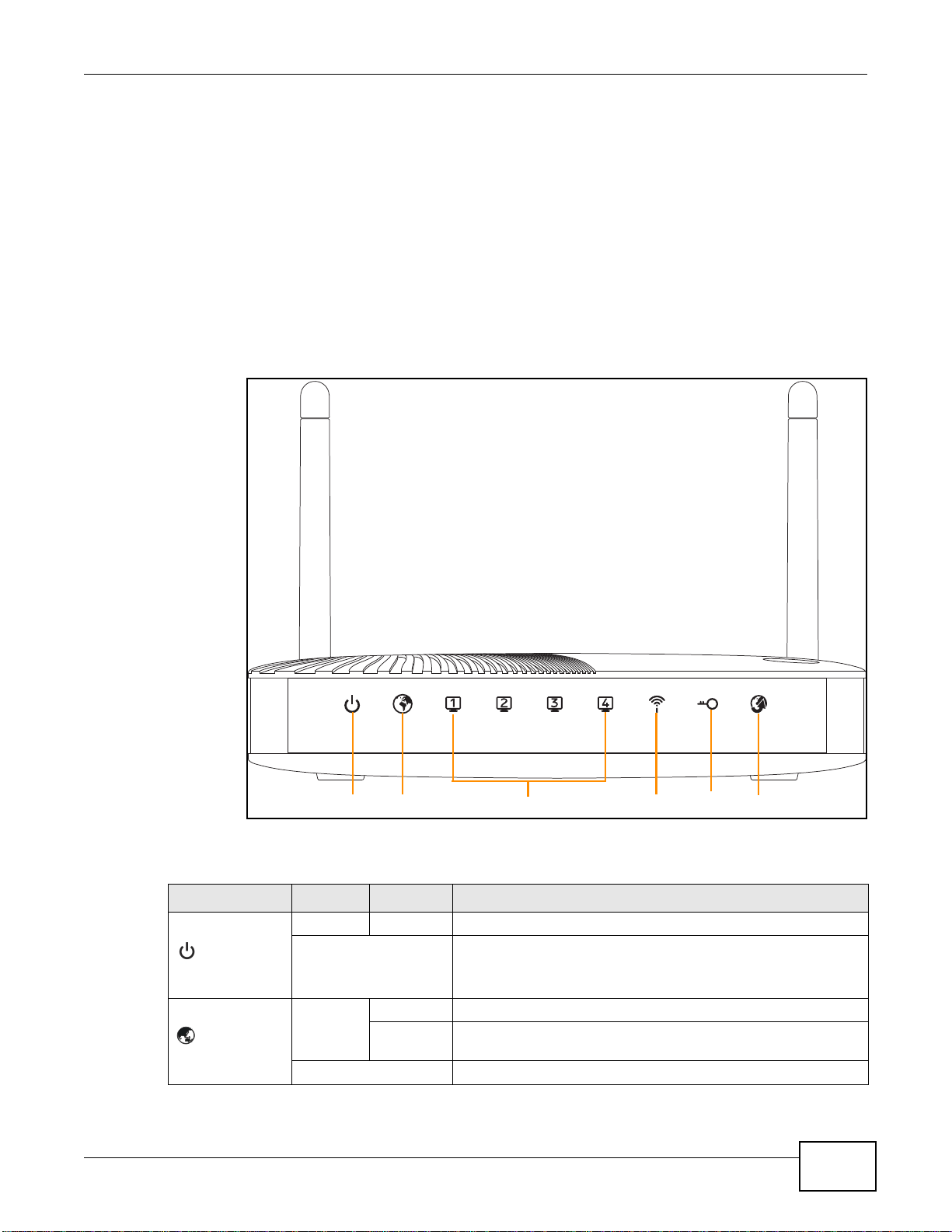
Power WAN Ethernet WLAN WPS Internet
types of characters, such as numbers and letters.
• Write down the password and put it in a safe place.
• Back up the configuration (and make sure you know how to restore it). Restoring an earlier
working configuration may be useful if the device becomes unstable or even crashes. If you
forget your password, you will have to reset the EMG2306-R10A to its factory default settings. If
you backed up an earlier configuration file, you would not have to totally re-configure the
EMG2306-R10A. You could simply restore your last configuration.
1.5 LEDs
Figure 1 Front Panel
Chapter 1 Introduction
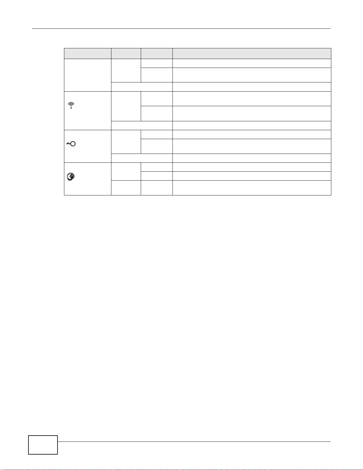
The following table describes the LEDs and the WPS button.
Table 1 Front panel LEDs and WPS button
LED COLOR STATUS DESCRIPTION
Green On The EMG2306-R10A is receiving power and functioning properly.
Off The EMG2306-R10A is not receiving power.
Power
Green On The EMG2306-R10A’s WAN connection is ready.
Blinking The EMG2306-R10A is sending/receiving data through the WAN
with a 10/100Mbps transmission rate.
WAN
EMG2306-R10A User’s Guide
Off The WAN connection is not ready, or has failed.
13
Page 14
Chapter 1 Introduction
Table 1 Front panel LEDs and WPS button (continued)
LED COLOR STATUS DESCRIPTION
LAN 1-4 Green On The EMG2306-R10A’s LAN connection is ready.
WLAN
WPS
(INTERNET)
Blinking The EMG2306-R10A is sending/receiving data through the LAN
with a 10/100Mbps transmission rate.
Off The LAN connection is not ready, or has failed.
Green On The EMG2306-R10A is ready, but is not sending/receiving data
through the wireless LAN.
Blinking The EMG2306-R10A is sending/receiving data through the
wireless LAN.
Off The wireless LAN is not ready or has failed.
Green On The WPS status is configured.
Blinking The EMG2306-R10A is negotiating a WPS connection with a
wireless client.
Off The WPS function is disabled on the EMG2306-R10A.
Green On Internet (WAN) connection is up (e.g. PPPeE/DHCP Client).
Blinking Internet connection established.
Off Internet connection is down.
1.6 The WPS Button
Your EMG2306-R10A supports WiFi Protected Setup (WPS), which is an easy way to set up a secure
wireless network. WPS is an industry standard specification, defined by the WiFi Alliance.
WPS allows you to quickly set up a wireless network with strong security, without having to
configure security settings manually. Each WPS connection works between two devices. Both
devices must support WPS (check each device’s documentation to make sure).
Depending on the devices you have, you can either press a button (on the device itself, or in its
configuration utility) or enter a PIN (a unique Personal Identification Number that allows one device
to authenticate the other) in each of the two devices. When WPS is activated on a device, it has two
minutes to find another device that also has WPS activated. Then, the two devices connect and set
up a secure network by themselves.
For more information on using WPS, see Section 7.2 on page 40.
14
EMG2306-R10A User’s Guide
Page 15
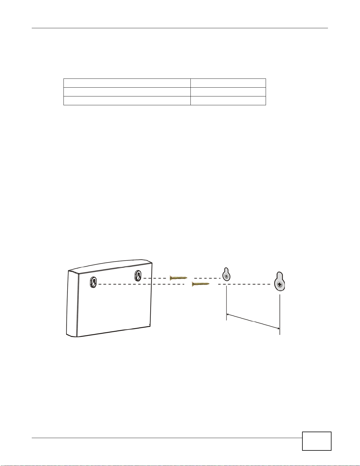
1.7 W all Mounting
You may need screw anchors if mounting on a concrete or brick wall.
Table 2 Wall Mounting Information
Distance between holes 12 cm
M4 Screws Two
Screw anchors (optional) Two
1 Select a position free of obstructions on a wall strong enough to hold the weight of the device.
2 Mark two holes on the wall at the appropriate distance apart for the screws.
Be careful to avoid damaging pipes or cables located inside the wall
when drilling holes for the screws.
3 If using screw anchors, drill two holes for the screw anchors into the wall. Push the anchors into the
full depth of the holes, then insert the screws into the anchors. Do not insert the screws all the way
in - leave a small gap of about 0.5 cm.
If not using screw anchors, use a screwdriver to insert the screws into the wall. Do not insert the
screws all the way in - leave a gap of about 0.5 cm.
Chapter 1 Introduction
4 Make sure the screws are fastened well enough to hold the weight of the EMG2306-R10A with the
connection cables.
5 Align the holes on the back of the EMG2306-R10A with the screws on the wall. Hang the EMG2306-
R10A on the screws.
Figure 2 Wall Mounting Example
EMG2306-R10A User’s Guide
15
Page 16

2.1 Overview
This chapter describes how to access the EMG2306-R10A Web Configurator and provides an
overview of its screens.
The Web Configurator is an HTML-based management interface that allows easy setup and
management of the EMG2306-R10A via Internet browser. Use Internet Explorer 6.0 and later
versions, Mozilla Firefox 3 and later versions, or Safari 2.0 and later versions. The recommended
screen resolution is 1024 by 768 pixels.
In order to use the Web Configurator you need to allow:
• Web browser pop-up windows from your device. Web pop-up blocking is enabled by default in
Windows XP SP (Service Pack) 2.
• JavaScript (enabled by default).
• Java permissions (enabled by default).
CHAPTER 2
Introducing the Web Configurator
Refer to the Troubleshooting chapter (Chapter 21 on page 148) to see how to make sure these
functions are allowed in Internet Explorer.
2.2 Login Accounts
There are two system accounts that you can use to log in to the EMG2306-R10A: “admin” and
“supervisor”. These two accounts have different privilege levels. The web configurator screens
vary depending on which account you use to log in.
The supervisor accounts allows you full access to all system configurations. The default supervisor
user name is “supervisor” and password is “supervisor”.
With the admin account, you cannot access Remote MGMT screens and can only view the Sys OP
Mode screen. The default username is “admin” and password is “1234”.
2.3 Accessing the Web Configurator
1 Make sure your EMG2306-R10A hardware is properly connected and prepare your computer or
computer network to connect to the EMG2306-R10A (refer to the Quick Start Guide).
EMG2306-R10A User’s Guide 16
Page 17
Chapter 2 Introducing the Web Configurator
2 Launch your web browser.
3 Type "http://192.168.1.1" as the website address.
Your computer must be in the same subnet in order to access this website address.
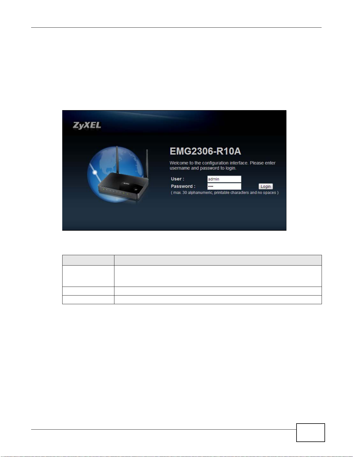
4 If you are logging in with the “admin” account, type “1234” (default) as the password.
If you are logging in with the “supervisor” account, type “supervisor” (default) as the password.
Then click Login.
Figure 3 Admin Account Login
The following table describes the labels in this screen.
Table 3 Login screen
LABEL DESCRIPTION
User Name Type “admin” or “supervisor” as the user name.
Note: Admin is displayed in Figure 3.
Password Type “1234” (default) as the password.
Login Click Login to enter the EMG2306-R10A’s web configurator.
EMG2306-R10A User’s Guide
17
Page 18
Chapter 2 Introdu cing the Web Configurator
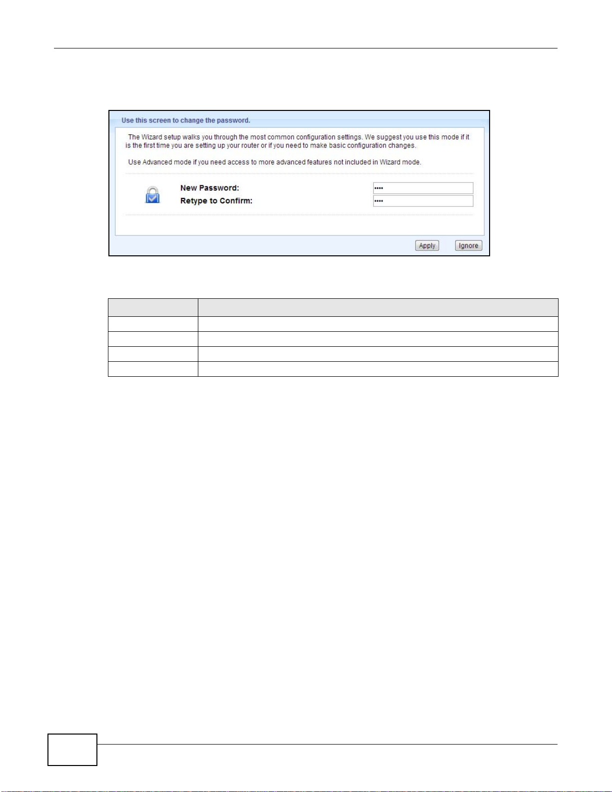
5 You should see a screen asking you to change your password (highly recommended) as shown
next. Type a new password (and retype it to confirm) and click Apply or click Ignore.
Figure 4 Change Password Screen
The following table describes the labels in this screen.
Table 4 Change Password Screen
LABEL DESCRIPTION
New Password Type a new password.
Retype to Confirm Retype the password for confirmation.
Apply Click Apply to save your changes back to the EMG2306-R10A.
Ignore Click Ignore if you do not want to change the password this time.
Note: The management session automatically times out when the time period set in the
Administrator Inactivity Timer field expires (default five minutes; go to Chapter
20 on page 137 to change this). Simply log back into the EMG2306-R10A if this
happens.
2.4 Resetting the EMG2306-R10A
If you forget your password or IP address, or you cannot access the Web Configurator, you will need
to use the RESET button at the back of the EMG2306-R10A to reload the factory-default
configuration file. This means that you will lose all configurations that you had previously saved, the
password will be reset to “1234” and the IP address will be reset to “192.168.1.1”.
2.4.1 Procedure to Use the RESET Button
1 Make sure the power LED is on.
2 Press the RESET button for longer than 1 second to restart/reboot the EMG2306-R10A.
3 Press the RESET button for longer than 5 seconds to set the EMG2306-R10A back to its factory-
default configurations.
18
EMG2306-R10A User’s Guide
Page 19
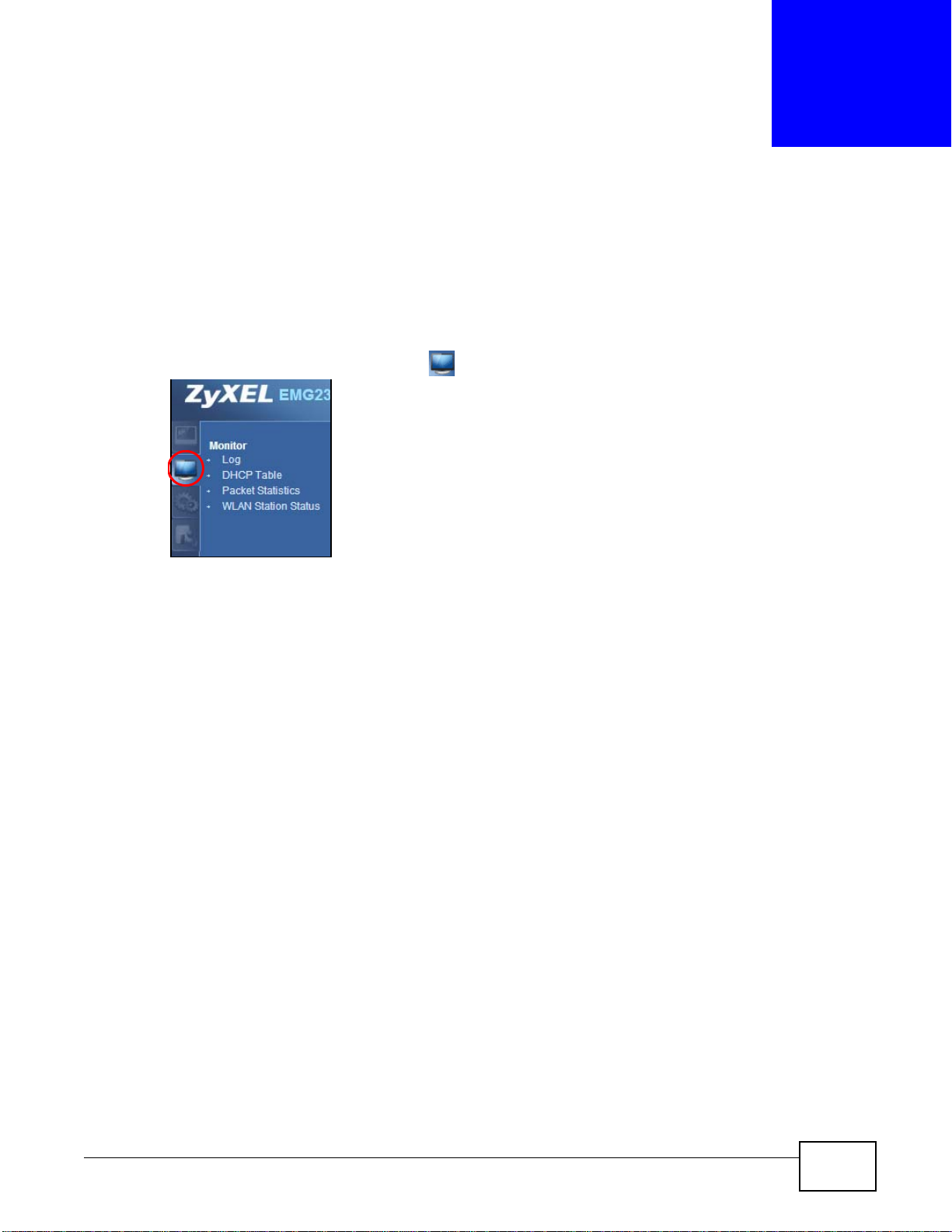
3.1 Overview
This chapter discusses read-only information related to the device state of the EMG2306-R10A.
To access the Monitor screens, click . Click open all to show the complete menu.
CHAPTER 3
Monitor
You can also click the links in the Summary table of the Status screen to view the bandwidth
consumed, packets sent/received as well as the status of clients connected to the EMG2306-R10A.
3.2 What You Can Do
•Use the Log screen to see the logs for the activity on the EMG2306-R10A (Section 3.3 on page
19).
•Use the DHCP Table screen to view information related to your DHCP status (Section 3.4 on
page 20).
•use the Packet Statistics screen to view port statistics and the "system up time" (Section 3.5
on page 22).
•Use the WLAN Station Status screen to view the wireless stations that are currently associated
to the EMG2306-R10A (Section 3.6 on page 23).
3.3 The Log Screen
The Web Configurator allows you to look at all of the EMG2306-R10A’s logs in one location.
EMG2306-R10A User’s Guide 19
Page 20
Chapter 3 Monitor
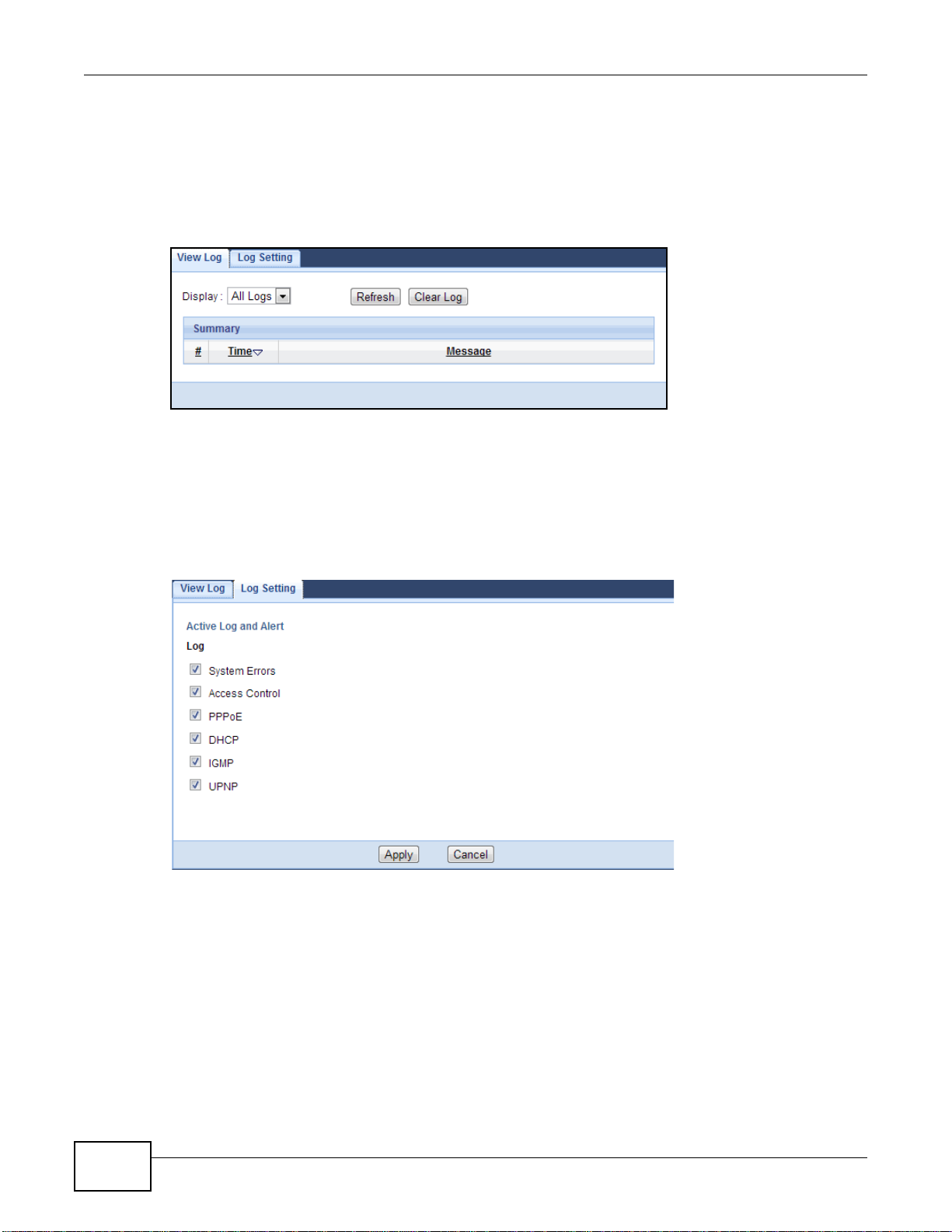
3.3.1 View Log
Click Monitor > Log to open the View Log screen. You can see the logged messages for the
EMG2306-R10A. The log wraps around and deletes the old entries after it fills. Click Clear Log to
delete all the logs. Click Refresh to renew the log screen.
Figure 5 View Log
3.3.2 Log Setting
You can configure which logs to display in the View Log screen. Click Monitor > Log to open the
Log Setting screen and select the logs you wish to display. You can configure active log and alert
settings.
Figure 6 Log Setting
3.4 DHCP Table
Dynamic Host Configuration Protocol (DHCP), RFC 2131 and RFC 2132 allow individual clients to
obtain TCP/IP configuration at start-up from a server. You can configure the EMG2306-R10A’s LAN
as a DHCP server or disable it. When configured as a server, the EMG2306-R10A provides the
TCP/IP configuration for the clients. If DHCP service is disabled, you must have another DHCP
server on that network, or else the computer must be manually configured.
20
EMG2306-R10A User’s Guide
Page 21
Chapter 3 Monitor
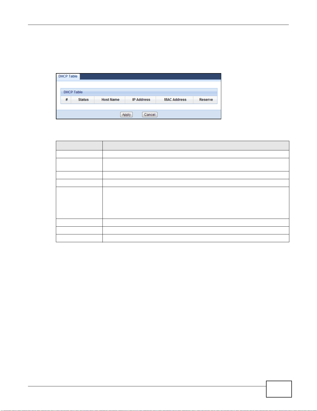
Click the DHCP Table (Details...) hyperlink in the Status screen or Monitor > DHCP Table.
Read-only information here relates to your DHCP status. The DHCP table shows current DHCP client
information (including Host Name, IP Address, and Mac Address) of all network clients using
the EMG2306-R10A’s DHCP server.
Figure 7 Summary: DHCP Table
The following table describes the labels in this screen.
Table 5 Summary: DHCP Table
LABEL DESCRIPTION
# This is the index number of the host computer.
Status This field displays weather the connection to the host computer is up (a yellow bulb) or
down (a grey bulb).
Host Name This field displays the computer host name.
IP Address This field displays the IP address relative to the # field listed above.
MAC Address This field shows the MAC address of the computer with the name in the Host Name
field.
Every Ethernet device has a unique MAC (Media Access Control) address which uniquely
identifies a device. The MAC address is assigned at the factory and consists of six pairs
of hexadecimal characters, for example, 00:A0:C5:00:00:02.
Reserve Select this if you want to reserve the IP address for this specific MAC address.
Apply Click Apply to save your changes back to the EMG2306-R10A.
Cancel Click Cancel to exit this screen without saving.
EMG2306-R10A User’s Guide
21
Page 22
Chapter 3 Monitor
3.5 Packet Statistics
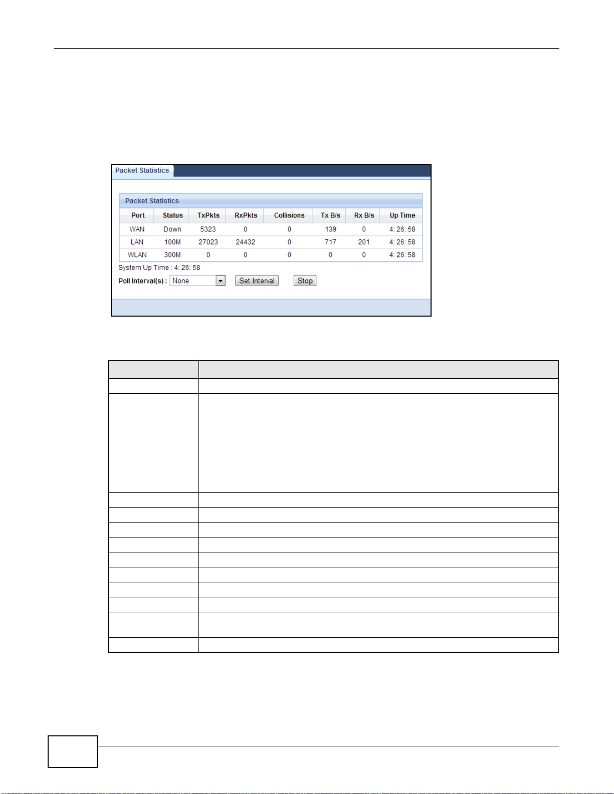
Click the Packet Statistics (Details...) hyperlink in the Status screen or Monitor > Packet
Statistics. Read-only information here includes port statistics and the "system up time". The Poll
Interval(s) field is configurable and is used for refreshing the screen.
Figure 8 Summary: Packet Statistics
The following table describes the labels in this screen.
Table 6 Summary: Packet Statistics
LABEL DESCRIPTION
Port This is the EMG2306-R10A’s port type.
Status For the LAN ports, this displays the port speed and duplex setting or Down when the
line is disconnected.
For the WAN port, it displays the port speed and duplex setting if you’re using Ethernet
encapsulation and Idle (line (ppp) idle), Dial (starting to trigger a call) and Drop
(dropping a call) if you’re using PPPoE or PPTP encapsulation. This field displays Down
when the line is disconnected.
For the WLAN, it displays the maximum transmission rate when the WLAN is enabled
and Down when the WLAN is disabled.
TxPkts This is the number of transmitted packets on this port.
RxPkts This is the number of received packets on this port.
Collisions This is the number of collisions on this port.
Tx B/s This displays the transmission speed in bytes per second on this port.
Rx B/s This displays the reception speed in bytes per second on this port.
Up Time This is the total time the EMG2306-R10A has been for each session.
System Up Time This is the total time the EMG2306-R10A has been on.
Poll Interval(s) Enter the time interval in seconds for refreshing statistics in this field.
Set Interval Click this button to apply the new poll interval you entered in the Poll Interval(s)
field.
Stop Click Stop to stop refreshing statistics.
22
EMG2306-R10A User’s Guide
Page 23
3.6 WLAN Station Status
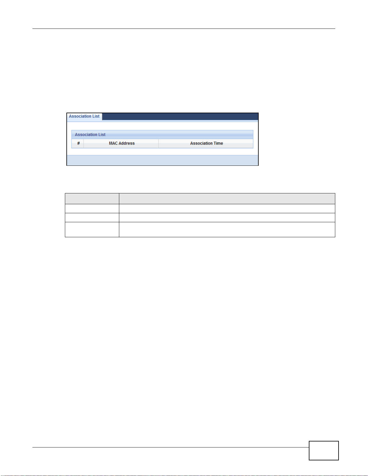
Click the WLAN Station Status (Details...) hyperlink in the Status screen or Monitor > WLAN
Station Status. View the wireless stations that are currently associated to the EMG2306-R10A in
the Association List. Association means that a wireless client (for example, your network or
computer with a wireless network card) has connected successfully to the AP (or wireless router)
using the same SSID, channel and security settings.
Figure 9 Summary: Association List
The following table describes the labels in this screen.
Table 7 Summary: Wireless Association List
LABEL DESCRIPTION
# This is the index number of an associated wireless station.
MAC Address This field displays the MAC address of an associated wireless station.
Association Time This field displays the time a wireless station first associated with the EMG2306-R10A’s
WLAN network.
Chapter 3 Monitor
EMG2306-R10A User’s Guide
23
Page 24

4.1 Overview
This chapter introduces the operating mode of your EMG2306-R10A, or simply how the EMG2306R10A is being used in the network.
4.1.1 Device Modes
These are the operating mode of the EMG2306-R10A:
• Router: This is the default device mode of the EMG2306-R10A. Use this mode to connect the
local network to another network, like the Internet. Go to Section 5.2 on page 26 to view the
Status screen in this mode.
• Access Point: Use this mode if you want to extend your network by allowing network devices to
connect to the EMG2306-R10A wirelessly. Go to Section 6.4 on page 34 to view the Status
screen in this mode.
CHAPTER 4
EMG2306-R10A Modes
For more information on these modes and to change the mode of your EMG2306-R10A, refer to
Chapter 20 on page 146.
The menu for changing device modes is available when logged in as “supervisor” only, refer to
Chapter 2 on page 16.
Note: Choose your Device Mode carefully to avoid having to change it later.
When changing to another mode, the IP address of the EMG2306-R10A changes. The running
applications and services of the network devices connected to the EMG2306-R10A can be
interrupted.
EMG2306-R10A User’s Guide 24
Page 25
5.1 Overview
Modem
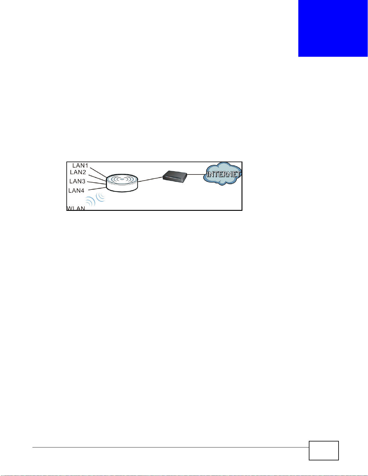
The EMG2306-R10A is set to router mode by default. Routers are used to connect the local network
to another network (for example, the Internet). In the figure below, the EMG2306-R10A connects
the local network (LAN1 ~ LAN4) to the Internet.
Figure 10 EMG2306-R10A Network
CHAPTER 5
Router Mode
EMG2306-R10A User’s Guide 25
Page 26
Chapter 5 Router Mode
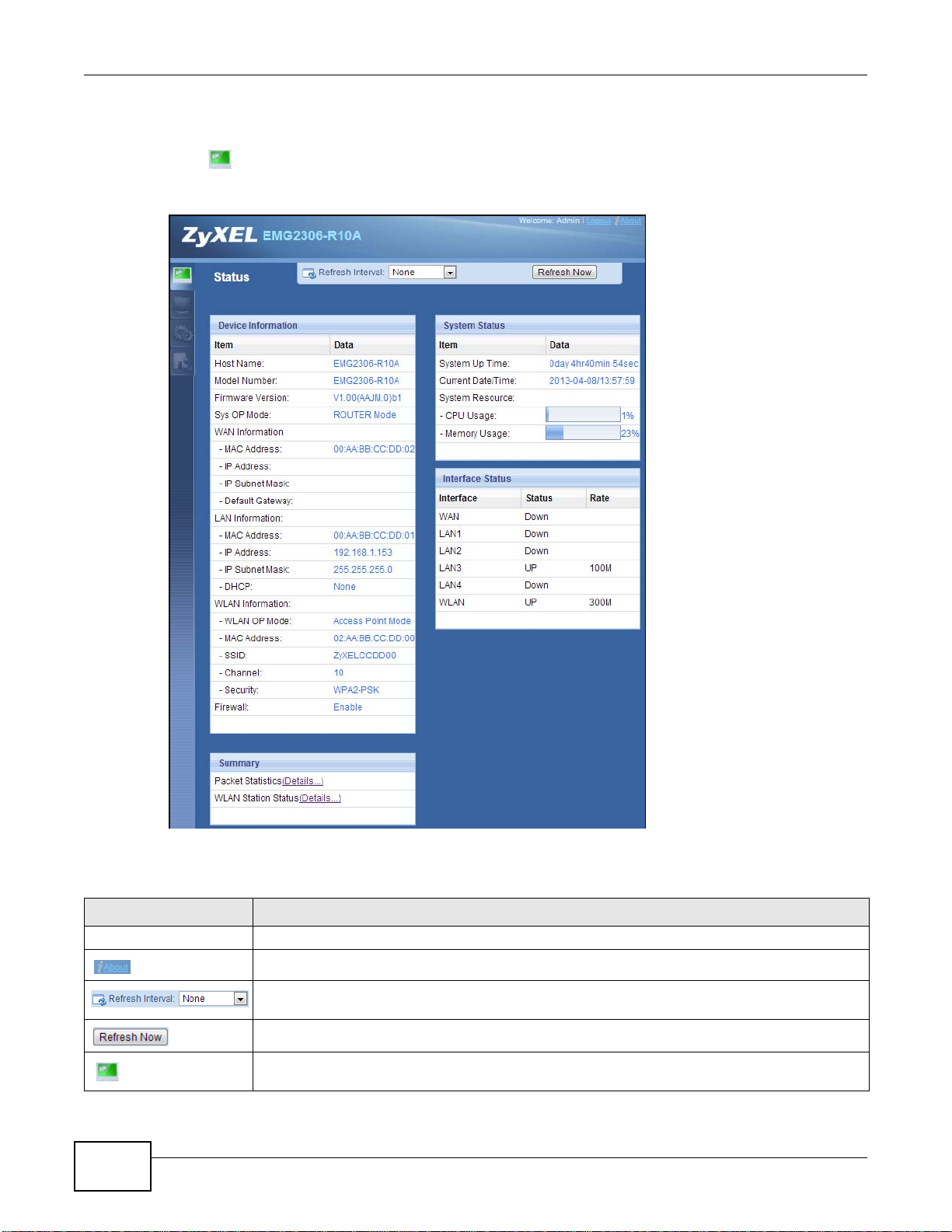
5.2 Router Mode Status Screen
Click to open the status screen.
Figure 11 Status Screen: Router Mode
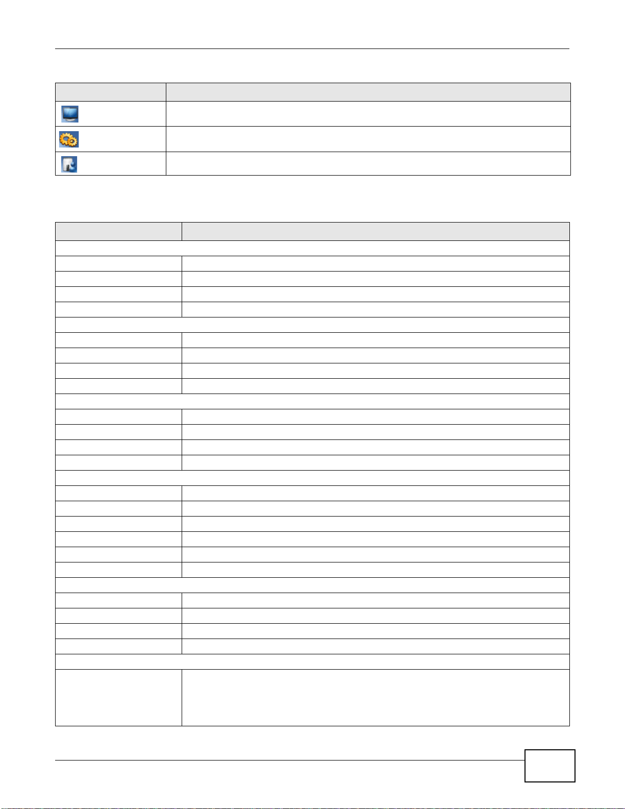
The following table describes the icons shown in the Status screen.
Table 8 Status Screen Icon Key: Router Mode
ICON DESCRIPTION
Logout Click this at any time to exit the Web Configurator.
Click this icon to view copyright and a link for related product information.
Select a number of seconds or None from the drop-down list box to refresh all screen statistics
automatically at the end of every time interval or to not refresh the screen statistics.
Click this button to refresh the status screen statistics.
Click this icon to see the Status page. The information in this screen depends on the device
mode you select.
26
EMG2306-R10A User’s Guide
Page 27
Chapter 5 Router Mode
Table 8 Status Screen Icon Key: Router Mode (continued)
ICON DESCRIPTION
Click this icon to see the Monitor navigation menu.
Click this icon to see the Configuration navigation menu.
Click this icon to see the Maintenance navigation menu.
The following table describes the labels shown in the Status screen.
Table 9 Status Screen: Router Mode
LABEL DESCRIPTION
Device Information
Host Name This is the device’s host name.
Model Number This is the device’s model number.
Firmware Version This is the firmware version.
Sys OP Mode This shows the device mode to which the EMG2306-R10A is set.
WAN Information
- MAC Address This shows the WAN Ethernet adapter MAC Address of your device.
- IP Address This shows the WAN port’s IP address.
- IP Subnet Mask This shows the WAN port’s subnet mask.
- Default Gateway This shows the default gateway address.
LAN Information
- MAC Address This shows the LAN Ethernet adapter MAC Address of your device.
- IP Address This shows the LAN port’s IP address.
- IP Subnet Mask This shows the LAN port’s subnet mask.
- DHCP This shows the LAN port’s DHCP role - Server or Disable.
WLAN Information
- WLAN OP Mode This shows the device mode to which the EMG2306-R10A’s wireless LAN is set.
- MAC Address This shows the wireless adapter MAC Address of your device.
- SSID This shows a descriptive name used to identify the EMG2306-R10A in the wireless LAN.
- Channel This shows the channel number which you select manually.
- Security This shows the level of wireless security the EMG2306-R10A is using.
Firewall This shows the firewall enabled or not.
System Status
Item This column shows the type of data the EMG2306-R10A is recording.
Data This column shows the actual data recorded by the EMG2306-R10A.
System Up Time This is the total time the EMG2306-R10A has been on.
Current Date/Time This field displays your EMG2306-R10A’s present date and time.
System Resource
- CPU Usage This displays what percentage of the EMG2306-R10A’s processing ability is currently used.
When this percentage is close to 100%, the EMG2306-R10A is running at full load, and the
throughput is not going to improve anymore. If you want some applications to have more
throughput, you should turn off other applications (for example, using bandwidth
management.)
EMG2306-R10A User’s Guide
27
Page 28
Chapter 5 Router Mode
Table 9 Status Screen: Router Mode (continued)
LABEL DESCRIPTION
- Memory Usage This shows what percentage of the heap memory the EMG2306-R10A is using.
System Setting
- UPnP This shows whether UPnP is enabled or not.
Interface Status
Interface This displays the EMG2306-R10A port types. The port types are: WAN, LAN and WLAN.
Status For the LAN and WAN ports, this field displays Down (line is down) or Up (line is up or
connected).
For the WLAN, it displays Up when the WLAN is enabled or Down when the WLAN is
disabled.
Rate For the LAN ports, this displays the port speed and duplex setting or N/A when the line is
disconnected.
For the WAN port, it displays the port speed and duplex setting if you’re using Ethernet
encapsulation. This field displays N/A when the line is disconnected.
For the WLAN, it displays the maximum transmission rate when the WLAN is enabled and N/
A when the WLAN is disabled.
WAN This shows the WAN status and data transfer rate.
LAN1 This shows the LAN1 status and data transfer rate.
LAN2 This shows the LAN2 status and data transfer rate.
LAN3 This shows the LAN3 status and data transfer rate.
LAN4 This shows the LAN4 status and data transfer rate.
WLAN This shows the WLAN status and data transfer rate.
Summary
Packet Statistics Click Details... to go to the Monitor > Packet Statistics screen (Section 3.5 on page 22).
Use this screen to view port status and packet specific statistics.
WLAN Station Status Click Details... to go to the Monitor > WLAN Station Status screen (Section 3.6 on page
23). Use this screen to view the wireless stations that are currently associated to the
EMG2306-R10A.
28
EMG2306-R10A User’s Guide
Page 29
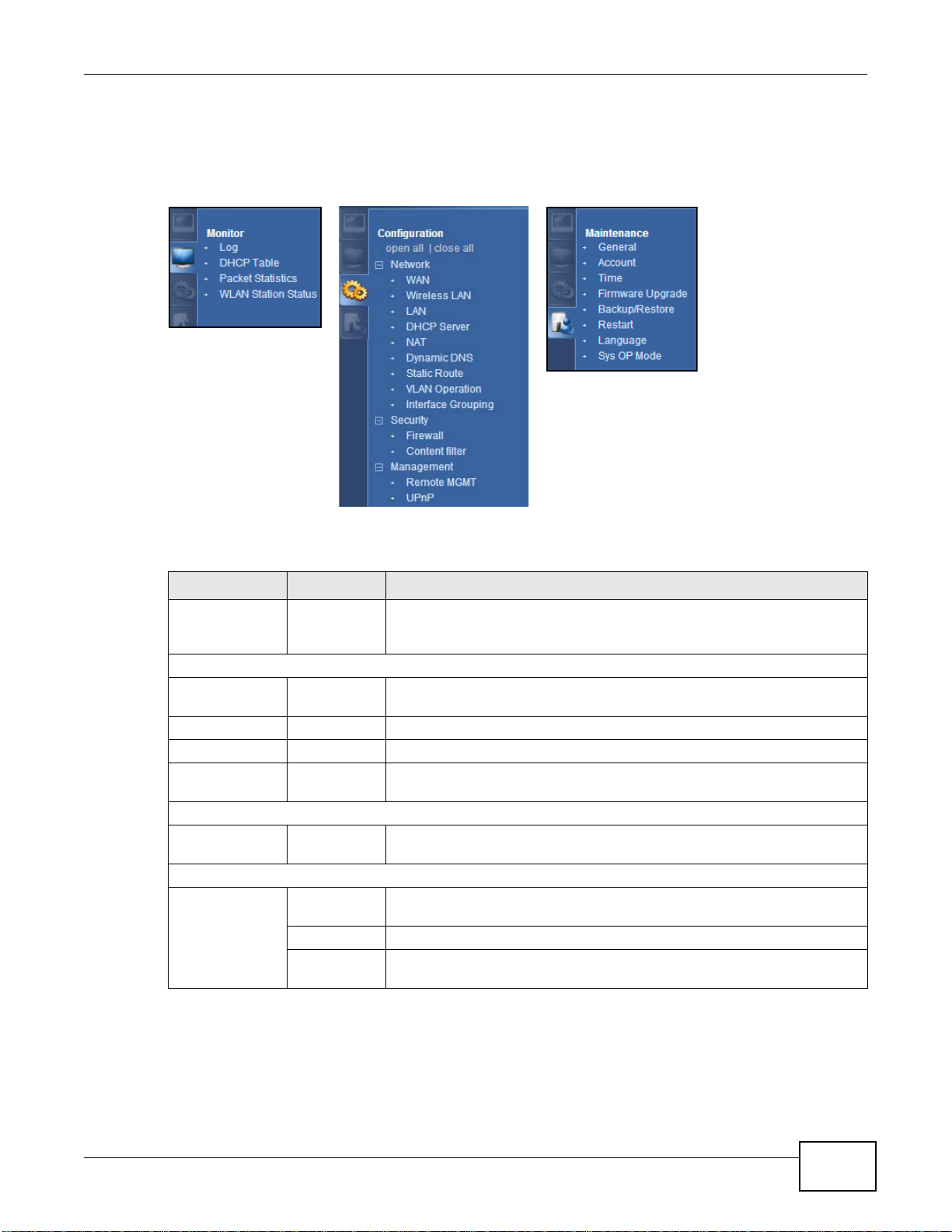
5.2.1 Navigation Panel
Use the sub-menus on the navigation panel to configure EMG2306-R10A features.
Figure 12 Navigation Panel: Router Mode
Chapter 5 Router Mode
The following table describes the sub-menus.
Table 10 Navigation Panel: Router Mode
LINK TAB FUNCTION
Status This screen shows the EMG2306-R10A’s general device, system and
interface status information. Use this screen to access the summary
statistics tables.
MONITOR
Log Use this screen to view the list of activities recorded by your EMG2306-
DHCP Table Use this screen to view current DHCP client information.
Packet Statistics Use this screen to view port status and packet specific statistics.
WLAN Station
Status
CONFIGURATION
Open all | close
all
Network
WAN Management
WAN
Advanced Use this screen to configure multicast and auto-subnet.
Add New
WAN Entries
R10A.
Use this screen to view the wireless stations that are currently associated
to the EMG2306-R10A.
Click Open all to see all the sub menus in Configuration section. Click
close all to close all the sub menus in Configuration section.
This screen allows you to configure ISP parameters, WAN IP address
assignment, DNS servers, the WAN MAC address, and VLAN settings.
Click to add new ISP parameters for Internet access.
EMG2306-R10A User’s Guide
29
Page 30

Chapter 5 Router Mode
Table 10 Navigation Panel: Router Mode (continued)
LINK TAB FUNCTION
Wireless LAN General Use this screen to configure wireless LAN and the level of wireless security
LAN IP Use this screen to configure LAN IP address and subnet mask.
DHCP Server General Use this screen to enable the EMG2306-R10A’s DHCP server.
NAT General Use this screen to enable NAT.
DDNS General Use this screen to set up dynamic DNS.
Static Route IP Static
Interface
Group
Security
Firewall General Use this screen to activate/deactivate the firewall and Anti-Dos Attack.
Content Filter Content Filter Use this screen to block sites containing certain keywords in the URL.
Management
Remote
MGMT
UPnP General Use this screen to enable UPnP on the EMG2306-R10A.
for the EMG2306-R10A.
More AP Use this screen to configure multiple BBs for the EMG2306-R10A.
MAC Filter Use the MAC filter screen to configure the EMG2306-R10A to block access
to devices or block the devices from accessing the EMG2306-R10A.
Advanced This screen allows you to configure advanced wireless settings.
QoS Use this screen to enable Wi-Fi Multimedia Quality of Service (WMM QoS).
WPS Use this screen to configure WPS.
WPS Station Use this screen to add a wireless station using WPS.
Scheduling Use this screen to schedule the times the Wireless LAN is enabled.
WDS Use this screen to set up Wireless Distribution System links to other access
IP Alias Use this screen to have the EMG2306-R10A apply IP alias to create LAN
Advanced Use this screen to assign IP addresses to specific individual computers
Client List Use this screen to view the individual client list.
Port
Forwarding
Port Trigger Use this screen to change EMG2306-R10A port triggering settings.
Route
Interface
Group
Services Use this screen to configure ICMP setting of the EMG2306-R10A.
WWW Use this screen to configure through which interface(s) and from which IP
Teln et Use this screen to configure through which interface(s) and from which IP
SNMP Use this screen to enable Wake on LAN to remotely turn on a device on the
TR069 Use this screen to configure the remote management over the WAN by an
Import CA Use this screen to import certificates (digital IDs) to authenticate users.
WMM QoS allows you to prioritize wireless traffic according to the delivery
requirements of individual services.
points.
subnets.
based on their MAC addresses and to have DNS servers assigned by the
DHCP server.
Use this screen to make your local servers visible to the outside world.
Use this screen to configure IP static routes.
Use this screen to add a LAN interface or a VLAN ID to a new group.
address(es) users can use HTTP to manage the EMG2306-R10A.
address(es) users can use Telnet to manage the EMG2306-R10A.
local network.
Auto Configuration Server (ACS).
30
EMG2306-R10A User’s Guide
Page 31

Chapter 5 Router Mode
Table 10 Navigation Panel: Router Mode (continued)
LINK TAB FUNCTION
MAINTENANCE
General General Use this screen to view and change administrative settings such as system
and domain names.
Account User Account Use this screen to change the password of your EMG2306-R10A.
Time Time Setting Use this screen to change your EMG2306-R10A’s time and date.
Firmware
Upgrade
Backup/
Restore
Reset/
Restart
Language Language Use this screen to select the language for your EMG2306-R10A interface.
Sys OP Mode Sys OP Mode This screen allows you to select whether your device acts as a Router or a
Firmware
Upgrade
Backup/
Restore
Restart This screen allows you to reboot the EMG2306-R10A without turning the
Use this screen to upload firmware to your EMG2306-R10A.
Use this screen to backup and restore the configuration or reset the factory
defaults to your EMG2306-R10A.
power off.
Access Point.
EMG2306-R10A User’s Guide
31
Page 32

6.1 Overview
WLAN
LAN
Use your EMG2306-R10A as an access point (AP) if you already have a router or gateway on your
network. In this mode your EMG2306-R10A bridges a wired network (LAN) and wireless LAN
(WLAN) in the same subnet. See the figure below for an example.
Figure 13 Wireless Internet Access in Access Point Mode
CHAPTER 6
Access Point Mode
Many screens that are available in Router mode are not available in Access Point mode, such as
bandwidth management and firewall.
Note: See Chapter 7 on page 40 for an example of setting up a wireless network in
Access Point mode.
6.2 What You Can Do
•Use the Status screen to view read-only information about your EMG2306-R10A (Section 6.4 on
page 34).
•Use the LAN screen to set the IP address for your EMG2306-R10A acting as an access point
(Section 6.5 on page 37).
6.3 What You Need to Know
See Chapter 7 on page 40 for a tutorial on setting up a network with the EMG2306-R10A as an
access point.
EMG2306-R10A User’s Guide 32
Page 33

6.3.1 Setting your EMG2306-R10A to AP Mode
1 Log into the Web Configurator if you haven’t already. See the Quick start Guide for instructions on
how to do this.
2 To use your EMG2306-R10A as an access point, go to Maintenance > Sys OP Mode > General
and select Access Point mode.
Figure 14 Changing to Access Point mode
Chapter 6 Access Point Mode
Note: You must logout of Web Configurator to complete the change mode process.
When you select Access Point Mode, the following pop-up message window appears.
Figure 15 Pop-up window for Access Point mode
3 Click OK. Then click Apply. The Web Configurator refreshes once the change to WISP Mode is
successful.
6.3.2 Accessing the Web Configurator in Access Point Mode
Log in to the Web Configurator in Access Point mode, do the following:
1 Connect your computer to the LAN port of the EMG2306-R10A.
2 The default IP address of the EMG2306-R10A is “192.168.1.2”. In this case, your computer must
have an IP address in the range between “192.168.1.3” and “192.168.1.254”.
3 Click Start > Run on your computer in Windows. Type “cmd” in the dialog box. Enter “ipconfig” to
show your computer’s IP address. If your computer’s IP address is not in the correct range then see
Appendix C on page 176 for information on changing your computer’s IP address.
EMG2306-R10A User’s Guide
33
Page 34

Chapter 6 Access Point Mode
4 After you’ve set your computer’s IP address, open a web browser such as Internet Explorer and
type “192.168.1.2” as the web address in your web browser.
6.3.3 Configuring your WLAN and Maintenance Settings
The configuration of wireless, bandwidth management and maintenance settings in Access Point
mode is the same as for Router Mode.
•See Chapter 9 on page 70 for information on the configuring your wireless network.
•See Chapter 20 on page 137 for information on configuring your Maintenance settings.
6.4 AP Mode Status Screen
Click to open the Status screen.
Figure 16 Status Screen: Access Point Mode
34
The following table describes the labels shown in the Status screen.
EMG2306-R10A User’s Guide
Page 35

Chapter 6 Access Point Mode
Table 11 Status Screen: Router Mode
LABEL DESCRIPTION
Device Information
Host Name This is the device’s host name.
Model Number This is the device’s model number.
Firmware Version This is the firmware version.
Sys OP Mode This shows the device mode to which the EMG2306-R10A is set.
LAN Information
- MAC Address This shows the LAN Ethernet adapter MAC Address of your device.
- IP Address This shows the LAN port’s IP address.
- IP Subnet Mask This shows the LAN port’s subnet mask.
- DHCP This shows the LAN port’s DHCP role - Server or Disable.
WLAN Information
- WLAN OP Mode This shows the device mode to which the EMG2306-R10A’s wireless LAN is set.
- MAC Address This shows the wireless adapter MAC Address of your device.
- SSID This shows a descriptive name used to identify the EMG2306-R10A in the wireless LAN.
- Channel This shows the channel number which you select manually.
- Security This shows the level of wireless security the EMG2306-R10A is using.
System Status
Item This column shows the type of data the EMG2306-R10A is recording.
Data This column shows the actual data recorded by the EMG2306-R10A.
System Up Time This is the total time the EMG2306-R10A has been on.
Current Date/Time This field displays your EMG2306-R10A’s present date and time.
System Resource
-CPU Usage This displays what percentage of the EMG2306-R10A’s processing ability is currently used.
When this percentage is close to 100%, the EMG2306-R10A is running at full load, and the
throughput is not going to improve anymore. If you want some applications to have more
throughput, you should turn off other applications (for example, using bandwidth
management.)
- Memory Usage This shows what percentage of the heap memory the EMG2306-R10A is using.
Interface Status
Interface This displays the EMG2306-R10A port types. The port types are: WAN, LAN and WLAN.
Status For the LAN and WAN ports, this field displays Down (line is down) or Up (line is up or
connected).
For the WLAN, it displays Up when the WLAN is enabled or Down when the WLAN is
disabled.
Rate For the LAN ports, this displays the port speed and duplex setting or N/A when the line is
disconnected.
For the WAN port, it displays the port speed and duplex setting if you’re using Ethernet
encapsulation. This field displays N/A when the line is disconnected.
For the WLAN, it displays the maximum transmission rate when the WLAN is enabled and N/
A when the WLAN is disabled.
LAN1 This shows the LAN1 status and data transfer rate.
LAN2 This shows the LAN2 status and data transfer rate.
EMG2306-R10A User’s Guide
35
Page 36

Chapter 6 Access Point Mode
Table 11 Status Screen: Router Mode (continued)
LABEL DESCRIPTION
LAN3 This shows the LAN3 status and data transfer rate.
LAN4 This shows the LAN4 status and data transfer rate.
WLAN This shows the WLAN status and data transfer rate.
Summary
Packet Statistics Click Details... to go to the Monitor > Packet Statistics screen (Section 3.5 on page 22).
Use this screen to view port status and packet specific statistics.
WLAN Station Status Click Details... to go to the Monitor > WLAN Station Status screen (Section 3.6 on page
23). Use this screen to view the wireless stations that are currently associated to the
EMG2306-R10A.
6.4.0.1 Navigation Panel
Use the menu in the navigation panel to configure EMG2306-R10A features in Access Point mode.
The following screen and table show the features you can configure in Access Point mode.
Figure 17 Menu: Access Point Mode
The following table describes the sub-menus.
Table 12 Navigation Panel: Router Mode
LINK TAB FUNCTION
Status This screen shows the EMG2306-R10A’s general device, system and
interface status information. Use this screen to access the summary
statistics tables.
MONITOR
Log Use this screen to view the list of activities recorded by your EMG2306-
Packet Statistics Use this screen to view port status and packet specific statistics.
WLAN Station
Status
CONFIGURATION
Open all | close
all
Network
R10A.
Use this screen to view the wireless stations that are currently associated
to the EMG2306-R10A.
Click Open all to see all the sub menus in Configuration section. Click
close all to close all the sub menus in Configuration section.
36
EMG2306-R10A User’s Guide
Page 37

Chapter 6 Access Point Mode
Table 12 Navigation Panel: Router Mode (continued)
LINK TAB FUNCTION
Wireless LAN General Use this screen to configure wireless LAN and the level of wireless security
for the EMG2306-R10A.
More AP Use this screen to configure multiple BBs for the EMG2306-R10A.
MAC Filter Use the MAC filter screen to configure the EMG2306-R10A to block access
to devices or block the devices from accessing the EMG2306-R10A.
Advanced This screen allows you to configure advanced wireless settings.
QoS Use this screen to enable Wi-Fi Multimedia Quality of Service (WMM QoS).
WPS Use this screen to configure WPS.
WPS Station Use this screen to add a wireless station using WPS.
Scheduling Use this screen to schedule the times the Wireless LAN is enabled.
WDS Use this screen to set up Wireless Distribution System links to other access
LAN IP Use this screen to configure LAN IP address and subnet mask.
IP Alias Use this screen to have the EMG2306-R10A apply IP alias to create LAN
MAINTENANCE
General General Use this screen to view and change administrative settings such as system
Account User Account Use this screen to change the password of your EMG2306-R10A.
Time Time Setting Use this screen to change your EMG2306-R10A’s time and date.
Firmware
Upgrade
Backup/
Restore
Restart Restart This screen allows you to reboot the EMG2306-R10A without turning the
Language Language Use this screen to select the language for your EMG2306-R10A interface.
Sys OP Mode Sys OP Mode This screen allows you to select whether your device acts as a Router or a
Firmware
Upgrade
Backup/
Restore
WMM QoS allows you to prioritize wireless traffic according to the delivery
requirements of individual services.
points.
subnets.
and domain names.
Use this screen to upload firmware to your EMG2306-R10A.
Use this screen to backup and restore the configuration or reset the factory
defaults to your EMG2306-R10A.
power off.
Access Point.
6.5 LAN Screen
Use this section to configure your LAN settings while in Access Point mode.
Click Configuration > Network > LAN to see the screen below.
EMG2306-R10A User’s Guide
37
Page 38

Chapter 6 Access Point Mode
Note: If you change the IP address of the EMG2306-R10A in the screen below, you will
need to log into the EMG2306-R10A again using the new IP address.
Figure 18 Configuration > Network > LAN > IP
The following table describes the labels in this screen.
Table 13 Configuration > Network > LAN > IP
LABEL DESCRIPTION
IP Address
Obtain an IP
Address
Automatically
Static IP Address Click this if you want to specify the IP address of your EMG2306-R10A. Or if your ISP or
IP Address Type the IP address in dotted decimal notation. The default setting is 192.168.1.2. If
Subnet Mask The subnet mask specifies the network number portion of an IP address. Your
Gateway IP Address Enter a Gateway IP Address (if your ISP or network administrator gave you one) in
DNS server
When you enable this, the EMG2306-R10A gets its IP address from the network’s DHCP
server (for example, your ISP). Users connected to the EMG2306-R10A can now access
the network (i.e., the Internet if the IP address is given by the ISP).
The Web Configurator may no longer be accessible unless you know the IP address
assigned by the DHCP server to the EMG2306-R10A. You need to reset the EMG2306R10A to be able to access the Web Configurator again (see Chapter 20 on page 143 for
details on how to reset the EMG2306-R10A).
Also, when you select this, you cannot enter an IP address for your EMG2306-R10A in
the field below.
network administrator gave you a static IP address to access the network or the
Internet.
you change the IP address you will have to log in again with the new IP address.
EMG2306-R10A will automatically calculate the subnet mask based on the IP address
that you assign. Unless you are implementing subnetting, use the subnet mask
computed by the EMG2306-R10A.
this field.
38
EMG2306-R10A User’s Guide
Page 39

Chapter 6 Access Point Mode
Table 13 Configuration > Network > LAN > IP (continued)
LABEL DESCRIPTION
First DNS Server
Second DNS Server
Third DNS Server
Apply Click Apply to save your changes back to the EMG2306-R10A.
Cancel Click Cancel to exit this screen without saving.
Select From ISP if your ISP dynamically assigns DNS server information (and the
EMG2306-R10A's WAN IP address). The field to the right displays the (read-only) DNS
server IP address that the ISP assigns.
Select User-Defined if you have the IP address of a DNS server. Enter the DNS
server's IP address in the field to the right. If you chose User-Defined, but leave the IP
address set to 0.0.0.0, User-Defined changes to None after you click Apply. If you
set a second choice to User-Defined, and enter the same IP address, the second
User-Defined changes to None after you click Apply.
Select None if you do not want to configure DNS servers. If you do not configure a DNS
server, you must know the IP address of a computer in order to access it.
EMG2306-R10A User’s Guide
39
Page 40

CHAPTER 7
7.1 Overview
This chapter provides tutorials for setting up your EMG2306-R10A.
• Set Up a Wireless Network with WPS
• Configure Wireless Security without WPS
• Using Multiple SSIDs on the EMG2306-R10A
7.2 Set Up a Wireless Network with WPS
This section gives you an example of how to set up wireless network using WPS. This example uses
the EMG2306-R10A as the AP and NWD210N as the wireless client which connects to a notebook.
Tutorials
Note: The wireless client must be a WPS-aware device (for example, a WPS USB adapter
or PCI card).
There are two WPS methods for creating a secure connection. This tutorial shows you how to do
both.
• Push Button Configuration (PBC) - create a secure wireless network simply by pressing a
button. See Section 7.2.1 on page 40.This is the easier method.
• PIN Configuration - create a secure wireless network simply by entering a wireless client's PIN
(Personal Identification Number) in the EMG2306-R10A’s interface. See Section 7.2.2 on page
41. This is the more secure method, since one device can authenticate the other.
7.2.1 Push Button Configuration (PBC)
1 Make sure that your EMG2306-R10A is turned on. Make sure the device is placed within range of
your computer.
2 Make sure that you have installed the wireless client (this example uses the NWD210N) driver and
utility in your notebook.
3 In the wireless client utility, find the WPS settings. Enable WPS and press the WPS button (Start or
WPS button)
4 Log into EMG2306-R10A’s Web Configurator and press the Push Button in the Configuration >
Network > Wireless LAN > WPS Station screen.
EMG2306-R10A User’s Guide 40
Page 41

Chapter 7 Tutorials
Wireless Client
Access Point
SECURITY INFO
COMMUNICATION
WITHIN 2 MINUTES
Note: Your EMG2306-R10A has a WPS button located on top panel, as well as a WPS
button in its configuration utility. Both buttons have exactly the same function; you
can use one or the other.
Note: It doesn’t matter which button is pressed first. You must press the second button
within two minutes of pressing the first one.
The EMG2306-R10A sends the proper configuration settings to the wireless client. This may take up
to two minutes. Then the wireless client is able to communicate with the EMG2306-R10A securely.
The following figure shows you an example to set up wireless network and security by pressing a
button on both EMG2306-R10A and wireless client (the NWD210N in this example).
Figure 19 Example WPS Process: PBC Method
7.2.2 PIN Configuration
When you use the PIN configuration method, you need to use both EMG2306-R10A’s configuration
interface and the client’s utilities.
1 Launch your wireless client’s configuration utility. Go to the WPS settings and select the PIN method
to get a PIN number.
2 Enter the PIN number to the PIN field in the Configuration > Network > Wireless LAN > WPS
Station screen on the EMG2306-R10A.
EMG2306-R10A User’s Guide
41
Page 42

Chapter 7 Tutorials
WITHIN 2 MINUTES
Wireless Client
Access Point
3 Click Start buttons (or button next to the PIN field) on both the wireless client utility screen and the
EMG2306-R10A’s WPS Station screen within two minutes.
The EMG2306-R10A authenticates the wireless client and sends the proper configuration settings to
the wireless client. This may take up to two minutes. Then the wireless client is able to
communicate with the EMG2306-R10A securely.
The following figure shows you the example to set up wireless network and security on EMG2306R10A and wireless client (ex. NWD210N in this example) by using PIN method.
Figure 20 Example WPS Process: PIN Method
7.3 Configure Wireless Security without WPS
This example shows you how to configure wireless security settings with the following parameters
on your EMG2306-R10A.
SSID SSID_Example
Channel 6
Security WPA-PSK
(Pre-Shared Key: ThisismyWPA-PSKpre-sharedkey)
Follow the steps below to configure the wireless settings on your EMG2306-R10A.
42
EMG2306-R10A User’s Guide
Page 43

Chapter 7 Tutorials
The instructions require that your hardware is connected (see the Quick Start Guide) and you are
logged into the Web Configurator through your LAN connection (see Section 2.3 on page 16).
1 Make sure the WLAN switch (at the back panel of the EMG2306-R10A) is set to ON.
2 Open the Configuration > Network > Wireless LAN > General screen in the AP’s Web
Configurator.
3 Confirm that the status of wireless LAN is ON.
4 Enter SSID_Example3 as the SSID and select Channel-06 as the channel. Set security to WPA2-
PSK and enter ThisismyWPA-PSKpre-sharedkey in the Pre-Shared Key field. Click Apply.l
EMG2306-R10A User’s Guide
43
Page 44

Chapter 7 Tutorials
5 Open the Status screen. Verify your wireless and wireless security settings under Device
Information and check if the WLAN connection is up under Interface Status.
7.3.1 Configure Your No tebook
Note: We use the ZyXEL M-302 wireless adapter utility screens as an example for the
wireless client. The screens may vary for different models.
1 The EMG2306-R10A supports IEEE 802.11b, IEEE 802.11g and IEEE 802.11n wireless clients. Make
sure that your notebook or computer’s wireless adapter supports one of these standards.
2 Wireless adapters come with software sometimes called a “utility” that you install on your
computer. See your wireless adapter’s User’s Guide for information on how to do that.
3 After you’ve installed the utility, open it. If you cannot see your utility’s icon on your screen, go to
Start > Programs and click on your utility in the list of programs that appears. The utility displays
a list of APs within range, as shown in the example screen below.
44
EMG2306-R10A User’s Guide
Page 45

4 Select SSID_Example3 and click Connect.
5 Select WPA-PSK and type the security key in the following screen. Click Next.
Chapter 7 Tutorials
6 The Confirm Save window appears. Check your settings and click Save to continue.
EMG2306-R10A User’s Guide
45
Page 46

Chapter 7 Tutorials
7 Check the status of your wireless connection in the screen below. If your wireless connection is
weak or you have no connection, see Chapter 21 Troubleshooting section of this User’s Guide.
If your connection is successful, open your Internet browser and enter http://www.zyxel.com or the
URL of any other web site in the address bar. If you are able to access the web site, your wireless
connection is successfully configured.
7.4 Using Multiple SSIDs on the EMG2306-R10A
You can configure more than one SSID on a EMG2306-R10A when it is operating in access point or
universal repeater mode. This allows you to configure multiple independent wireless networks on
the EMG2306-R10A as if there were multiple APs (virtual APs). Each virtual AP has its own SSID,
wireless security type and MAC filtering settings. That is, each SSID on the EMG2306-R10A
represents a different access point/wireless network to wireless clients in the network.
Clients can associate only with the SSIDs for which they have the correct security settings. Clients
using different SSIDs can access the Internet and the wired network behind the EMG2306-R10A
(such as a printer). You can allow communication between wireless clients of different SSIDs in the
Configuration > Network > Wireless LAN > General screen. See Section 9.4 on page 73 for
more information.
46
EMG2306-R10A User’s Guide
Page 47

Chapter 7 Tutorials
A
B
C
SSID_Guest
SSID_Worker
SSID_VoIP
For example, you may set up three wireless networks (A, B and C) in your office. A is for workers,
B is for guests and C is specific to a VoIP device in the meeting room.
7.4.1 Configuring Security Settings of Multiple SSIDs
The EMG2306-R10A is in router mode by default.
This example shows you how to configure the SSIDs with the following parameters on your
EMG2306-R10A (in router mode).
SSID SECURITY TYPE KEY MAC FILTERING
SSID_Worker WPA2-PSK
WPA Compatible
SSID_VoIP WPA-PSK VoIPOnly12345678 Allow
SSID_Guest WPA-PSK keyexample123 Disable
1 Connect your computer to the LAN port of the EMG2306-R10A using an Ethernet cable.
2 The default IP address of the EMG2306-R10A in router mode is “192.168.1.1”. In this case, your
computer must have an IP address in the range between “192.168.1.2” and “192.168.1.254”.
3 Click Start > Run on your computer in Windows. Type “cmd” in the dialog box. Enter “ipconfig” to
show your computer’s IP address. If your computer’s IP address is not in the correct range then see
Appendix C on page 176 for information on changing your computer’s IP address.
DoNotStealMyWirelessNetwork Disable
00:A0:C5:01:23:45
4 After you’ve set your computer’s IP address, open a web browser such as Internet Explorer and
type “http://192.168.1.1” as the web address in your web browser.
5 Enter “1234” (default) as the password and click Login.
EMG2306-R10A User’s Guide
47
Page 48

Chapter 7 Tutorials
6 Type a new password and retype it to confirm, then click Apply. Otherwise, click Ignore.
7 Go to Configuration > Network > Wireless LAN > More AP. Click the Edit icon of the first
entry to configure wireless and security settings for SSID_Worker.
8 Configure the screen as follows. In this example, you enable Intra-BSS Traffic for SSID_Worker
to allow wireless clients in the same wireless network to communicate with each other. Click Apply.
9 Click the Edit icon of the second entry to configure wireless and security settings for SSID_VoIP.
10 Configure the screen as follows. You do not enable Intra-BSS Traffic for SSID_VoIP. Click Apply.
48
EMG2306-R10A User’s Guide
Page 49

Chapter 7 Tutorials
11 Click the Edit icon of the third entry to configure wireless and security settings for SSID_Guest.
12 Configure the screen as follows. In this example, you enable Intra-BSS Traffic for SSID_Guest to
allow wireless clients in the same wireless network to communicate with each other. Select Enable
Guest WLAN to allow clients to access the Internet only. Click Apply.
EMG2306-R10A User’s Guide
49
Page 50

Chapter 7 Tutorials
13 Click the MAC Filter tab to configure MAC filtering for the SSID_VoIP wireless network. Select
SSID_VoIP from the SSID Select drop-down list, enable MAC address filtering and set the Filter
Action to Allow. Enter the VoIP device’s MAC address in the Mac Address field and click Apply to
allow only the VoIP device to associate with the EMG2306-R10A using this SSID.
50
EMG2306-R10A User’s Guide
Page 51

Chapter 7 Tutorials
EMG2306-R10A User’s Guide
51
Page 52

PART II
Technical Reference
52
Page 53

53
Page 54

8.1 Overview
LAN
WAN
This chapter discusses the EMG2306-R10A’s WAN screens. Use these screens to configure your
EMG2306-R10A for Internet access.
A WAN (Wide Area Network) connection is an outside connection to another network or the
Internet. It connects your private networks such as a LAN (Local Area Network) and other
networks, so that a computer in one location can communicate with computers in other locations.
Figure 21 LAN and WAN
CHAPTER 8
WAN
8.2 What You Can Do
•Use the Management WAN screen to enter your ISP information and set how the computer
acquires its IP, DNS and WAN MAC addresses (Section 8.4 on page 57).
•Use the Advanced screen to enable multicasting and auto-IP-change (Section 8.5 on page 68).
8.3 What You Need To Know
The information in this section can help you configure the screens for your WAN connection, as well
as enable/disable some advanced features of your EMG2306-R10A.
EMG2306-R10A User’s Guide 54
Page 55

8.3.1 Configuring Your Internet Connection
Encapsulation Method
Encapsulation is used to include data from an upper layer protocol into a lower layer protocol. To set
up a WAN connection to the Internet, you need to use the same encapsulation method used by your
ISP (Internet Service Provider). If your ISP offers a dial-up Internet connection using PPPoE (PPP
over Ethernet) or PPTP (Point-to-Point Tunneling Protocol), they should also provide a username
and password (and service name) for user authentication.
WAN IP Address
The WAN IP address is an IP address for the EMG2306-R10A, which makes it accessible from an
outside network. It is used by the EMG2306-R10A to communicate with other devices in other
networks. It can be static (fixed) or dynamically assigned by the ISP each time the EMG2306-R10A
tries to access the Internet.
If your ISP assigns you a static WAN IP address, they should also assign you the subnet mask and
DNS server IP address(es) (and a gateway IP address if you use the Ethernet or ENET ENCAP
encapsulation method).
Chapter 8 WAN
DNS Server Address Assignment
Use Domain Name System (DNS) to map a domain name to its corresponding IP address and vice
versa, for instance, the IP address of www.zyxel.com is 204.217.0.2. The DNS server is extremely
important because without it, you must know the IP address of a computer before you can access
it.
The EMG2306-R10A can get the DNS server addresses in the following ways.
1 The ISP tells you the DNS server addresses, usually in the form of an information sheet, when you
sign up. If your ISP gives you DNS server addresses, manually enter them in the DNS server fields.
2 If your ISP dynamically assigns the DNS server IP addresses (along with the EMG2306-R10A’s WAN
IP address), set the DNS server fields to get the DNS server address from the ISP.
WAN MAC Address
The MAC address screen allows users to configure the WAN port's MAC address by either using the
factory default or cloning the MAC address from a computer on your LAN. Choose Factory Default
to select the factory assigned default MAC Address.
Otherwise, click Clone the computer's MAC address - IP Address and enter the IP address of
the computer on the LAN whose MAC you are cloning. Once it is successfully configured, the
address will be copied to configuration file. It is recommended that you clone the MAC address prior
to hooking up the WAN Port.
Maximum Transmission Unit
A maximum transmission unit (MTU) is the largest size packet or frame, specified in octets (eightbit bytes) that can be sent in a packet- or frame-based network. The Transmission Control Protocol
EMG2306-R10A User’s Guide
55
Page 56

Chapter 8 WAN
A
B
C
D
Server
(TCP) uses the MTU to determine the maximum size of each packet in any transmission. Too large
an MTU size may mean retransmissions if the packet encounters a router that can't handle that
large a packet. Too small an MTU size means relatively more header overhead and more
acknowledgements that have to be sent and handled.
8.3.2 Multicast
Traditionally, IP packets are transmitted in one of either two ways - Unicast (1 sender - 1 recipient)
or Broadcast (1 sender - everybody on the network). Multicast delivers IP packets to a group of
hosts on the network - not everybody and not just 1.
Figure 22 Multicast Example
In the multicast example above, systems A and D comprise one multicast group. In multicasting,
the server only needs to send one data stream and this is delivered to systems A and D.
IGMP (Internet Group Multicast Protocol) is a network-layer protocol used to establish membership
in a multicast group - it is not used to carry user data. The EMG2306-R10A supports both IGMP
version 1 (IGMP-v1) and IGMP version 2 (IGMP-v2).
At start up, the EMG2306-R10A queries all directly connected networks to gather group
membership. After that, the EMG2306-R10A periodically updates this information. IP multicasting
can be enabled/disabled on the EMG2306-R10A LAN and/or WAN interfaces in the Web Configurator
(LAN; WAN). Select None to disable IP multicasting on these interfaces.
Auto-IP-Change
When the EMG2306-R10A gets a WAN IP address which is in the same subnet as the LAN IP
address 192.168.1.1, Auto-IP-Change allows the EMG2306-R10A to change its LAN IP address to
10.0.0.1 automatically. If the EMG2306-R10A’s original LAN IP address is 10.0.0.1 and the WAN IP
56
EMG2306-R10A User’s Guide
Page 57

Chapter 8 WAN
WAN
LAN
192.168.1.23192.168.1.1
10.0.0.1
address is in the same subnet, such as 10.0.0.3, the EMG2306-R10A switches to use 192.168.1.1
as its LAN IP address.
Figure 23 Auto-IP-Change
Auto-IP-Change only works under the following conditions:
• The EMG2306-R10A must be in Router Mode (see Chapter 20 on page 146 for more
information) for Auto-IP-Change to become active.
• The EMG2306-R10A is set to receive a dynamic WAN IP address using the Ethernet or PPPoE
connection type.
8.4 Management WAN
Use this screen to view, change, or add your EMG2306-R10A’s Internet access settings. Click
Configuration > Network > WAN. The following screen opens.
Figure 24 Configuration > Network > Management WAN
The following table describes the labels in this screen.
Table 14 Configuration > Network > Management WAN
LABEL DESCRIPTION
Add New WAN Entry Click this to create a new WAN interface entry.
# This is the index number of the connection.
Default Select the WAN interface that you want to configure as default.
Name This is the service name of the connection.
Interface This is the interface of the connection.
Type This shows the type of interface used by this connection.
VLAN ID This indicates the VLAN ID number assigned to traffic sent through this connection.
EMG2306-R10A User’s Guide
57
Page 58

Chapter 8 WAN
Table 14 Configuration > Network > Management WAN (continued)
LABEL DESCRIPTION
IP Address This is the WAN IP address used by this connection.
Status This shows the status of the connection.
Modify Click the Edit icon to configure the connection.
Click the Delete icon to delete this connection from the EMG2306-R10A. A window
displays asking you to confirm that you want to delete the connection.
8.4.1 Add/Edit Internet Connection
Click the Add New WAN Entry in the Configuration > WAN screen or the Edit icon next to the
connection you want to configure. Use this screen to configure a WAN connection. The screen varies
depending on the encapsulation you select.
58
EMG2306-R10A User’s Guide
Page 59

8.4.2 Ethernet Encapsulation
This screen displays when you select Ethernet encapsulation.
Figure 25 Internet Connection: Ethernet Encapsulation
Chapter 8 WAN
The following table describes the labels in this screen.
Table 15 Internet Connection: Ethernet Encapsulation
LABEL DESCRIPTION
ISP Parameters for Internet Access
Encapsulation Select the encapsulation type: PPPoE, PPTP, IPoE, or Bridge.
IPv4 / IPv6 Click the drop-down menu to select either an IPv4, IPv6 or dual stack interface.
IP Address Select Obtain an IP Address Automatically to have your ISP assign the parameters.
EMG2306-R10A User’s Guide
Select Static IP Address to enter a pre-defined IP Address, Subnet Mask, and
Gateway IP address.
59
Page 60

Chapter 8 WAN
Table 15 Internet Connection: Ethernet Encapsulation (continued)
LABEL DESCRIPTION
MTU Size Enter the Maximum Transmission Unit (MTU) or the largest packet size per frame that
your EMG2306-R10A can receive and process.
DHCP Option
Enable DHCP Option
121
Enable DHCP Option 60Select Enable DHCP Option 60 to enable and enter the device’s Vendor Class Identifier
DNS Server
First DNS Server
Second DNS Server
WAN MAC Address The MAC address section allows users to configure the WAN port's MAC address by
Factory default Select Factory default to use the factory assigned default MAC Address.
Clone the
computer’s MAC
address - IP
Address
WAN MAC Address
WAN MAC Address The MAC address section allows users to configure the WAN port's MAC address by
Factory default Select Factory default to use the factory assigned default MAC Address.
Clone the
computer’s MAC
address - IP
Address
Set WAN MAC
Address
Apply Click Apply to save your changes back to the EMG2306-R10A.
Reset Click Reset to reload the previous configuration for this screen.
Cancel Click Cancel to exit this screen without saving.
Select Enable DHCP Option 121 to enable the classless route option 121.
(VCI).
If you select Get automatically from ISP (Default) in the WAN IP Address
Assignment section, this field will automatically be set to From ISP. The field to the
right displays the (read-only) DNS server IP address that the ISP assigns.
If you select Use Fixed IP Address in the WAN IP Address Assignment section,
this field will automatically be set to User-Defined. Enter the DNS server's IP address
in the field to the right.
either using the EMG2306-R10A’s MAC address, copying the MAC address from a
computer on your LAN or manually entering a MAC address.
Select Clone the computer's MAC address - IP Address and enter the IP address of
the computer on the LAN whose MAC you are cloning.
using the EMG2306-R10A’s MAC address, copying the MAC address from a computer on
your LAN or manually entering a MAC address.
Select Clone the computer's MAC address - IP Address and enter the IP address of
the computer on the LAN whose MAC you are cloning.
Select this option and enter the MAC address you want to use.
8.4.3 PPPoE Encapsulation
The EMG2306-R10A supports PPPoE (Point-to-Point Protocol over Ethernet). PPPoE is an IETF
standard (RFC 2516) specifying how a personal computer (PC) interacts with a broadband modem
(DSL, cable, wireless, etc.) connection. The PPP over Ethernet option is for a dial-up connection
using PPPoE.
For the service provider, PPPoE offers an access and authentication method that works with existing
access control systems (for example Radius).
60
EMG2306-R10A User’s Guide
Page 61

Chapter 8 WAN
One of the benefits of PPPoE is the ability to let you access one of multiple network services, a
function known as dynamic service selection. This enables the service provider to easily create and
offer new IP services for individuals.
Operationally, PPPoE saves significant effort for both you and the ISP or carrier, as it requires no
specific configuration of the broadband modem at the customer site.
By implementing PPPoE directly on the EMG2306-R10A (rather than individual computers), the
computers on the LAN do not need PPPoE software installed, since the EMG2306-R10A does that
part of the task. Furthermore, with NAT, all of the LANs’ computers will have access.
This screen displays when you select PPP over Ethernet encapsulation.
Figure 26 Internet Connection: PPP over Ethernet Encapsulation
EMG2306-R10A User’s Guide
61
Page 62

Chapter 8 WAN
The following table describes the labels in this screen.
Table 16 Internet Connection: PPP over Ethernet Encapsulation
LABEL DESCRIPTION
ISP Parameters for Internet Access
Encapsulation Select PPP over Ethernet if you connect to your Internet via dial-up.
IPv4 / IPv6 Click the drop-down menu to select either an IPv4, IPv6 or dual stack interface.
IP Address Select Obtain an IP Address Automatically to have your ISP assign the parameters.
Select Static IP Address to enter a pre-defined IP Address, Subnet Mask, and
Gateway IP address.
MTU Size Enter the Maximum Transmission Unit (MTU) or the largest packet size per frame that
DHCP Option
Enable DHCP Option
121
Enable DHCP Option 60Select Enable DHCP Option 60 to enable and enter the device’s Vendor Class Identifier
DNS Server
IPv4 / IPv6 Click the drop-down menu to select either an IPv4, IPv6 or dual stack interface.
IP Address Select Obtain an IP Address Automatically to have your ISP assign the parameters.
MTU Size Enter the Maximum Transmission Unit (MTU) or the largest packet size per frame that
DHCP Option
Enable DHCP Option
121
Enable DHCP Option 60Select Enable DHCP Option 60 to enable and enter the device’s Vendor Class Identifier
DNS Server
First DNS Server
Second DNS Server
WAN MAC Address
WAN MAC Address The MAC address section allows users to configure the WAN port's MAC address by
Factory default Select Factory default to use the factory assigned default MAC Address.
Clone the
computer’s MAC
address - IP
Address
your EMG2306-R10A can receive and process.
Select Enable DHCP Option 121 to enable the classless route option 121.
(VCI).
Select Static IP Address to enter a pre-defined IP Address, Subnet Mask, and
Gateway IP address.
your EMG2306-R10A can receive and process.
Select Enable DHCP Option 121 to enable the classless route option 121.
(VCI).
Enter the VCI in the Vendor ID field.
Select From ISP if your ISP dynamically assigns DNS server information (and the
EMG2306-R10A's WAN IP address). The field to the right displays the (read-only) DNS
server IP address that the ISP assigns.
Select User-Defined if you have the IP address of a DNS server. Enter the DNS
server's IP address in the field to the right. If you chose User-Defined, but leave the
IP address set to 0.0.0.0, User-Defined changes to None after you click Apply. If you
set a second choice to User-Defined, and enter the same IP address, the second
User-Defined changes to None after you click Apply.
Select None if you do not want to configure DNS servers. If you do not configure a DNS
server, you must know the IP address of a computer in order to access it.
using the EMG2306-R10A’s MAC address, copying the MAC address from a computer on
your LAN or manually entering a MAC address.
Select Clone the computer's MAC address - IP Address and enter the IP address of
the computer on the LAN whose MAC you are cloning.
62
EMG2306-R10A User’s Guide
Page 63

Table 16 Internet Connection: PPP over Ethernet Encapsulation (continued)
LABEL DESCRIPTION
Set WAN MAC
Address
Apply Click Apply to save your changes back to the EMG2306-R10A.
Reset Click Reset to reload the previous configuration for this screen.
Cancel Click Cancel to exit this screen without saving.
Select this option and enter the MAC address you want to use.
8.4.4 PPTP Encapsulation
Point-to-Point Tunneling Protocol (PPTP) is a network protocol that enables secure transfer of data
from a remote client to a private server, creating a Virtual Private Network (VPN) using TCP/IPbased networks.
PPTP supports on-demand, multi-protocol and virtual private networking over public networks, such
as the Internet.
Chapter 8 WAN
EMG2306-R10A User’s Guide
63
Page 64

Chapter 8 WAN
This screen displays when you select PPTP encapsulation.
Figure 27 Internet Connection: PPTP Encapsulation
64
The following table describes the labels in this screen.
Table 17 Internet Connection: PPP over Ethernet Encapsulation
LABEL DESCRIPTION
ISP Parameters for Internet Access
Encapsulation Select PPTP to create a Virtual Private Network (VPN) using TCP/IP-based network.
IPv4 / IPv6 Click the drop down menu to select the available options: IPv4 only, dual stack, or
IPv6.
EMG2306-R10A User’s Guide
Page 65

Chapter 8 WAN
Table 17 Internet Connection: PPP over Ethernet Encapsulation (continued)
LABEL DESCRIPTION
PPTP Information
PPTP Username Type the username given to you by your ISP.
PPTP Password Type the password associated with the user name above.
MTU Size Enter the Maximum Transmission Unit (MTU) or the largest packet size per frame that
your EMG2306-R10A can receive and process.
PPTP Auto Connect Select this check box to enable PPTP Auto Connect.
Idle Timeout
(second)
PPTP Configuration
PPTP Server IP
Address
IP Address
Obtain an IP
Address
Automatically
Static IP Address Select this option If the ISP assigned a fixed IP address.
IP Address Enter your WAN IP address in this field if you selected Use Fixed IP Address.
Subnet Mask Your EMG2306-R10A will automatically calculate the subnet mask based on the IP
Gateway IP
address
WAN IP Address Assignment
Get automatically
from ISP
Use Fixed IP
Address
My WAN IP
Address
DNS Server
First DNS Server
Second DNS Server
WAN MAC Address
WAN MAC Address The MAC address section allows users to configure the WAN port's MAC address by
Factory default Select Factory default to use the factory assigned default MAC Address.
Clone the
computer’s MAC
address - IP
Address
This value specifies the time in minutes that elapses before the router automatically
disconnects from the PPPoE server.
Type the IP address of the PPTP server.
Select this option If your ISP did not assign you a fixed IP address. This is the default
selection.
address that you assign. Unless you are implementing subnetting, use the subnet mask
computed by the EMG2306-R10A.
Enter a Gateway IP Address (if your ISP gave you one) in this field.
Select this option If your ISP did not assign you a fixed IP address. This is the default
selection.
Select this option If the ISP assigned a fixed IP address.
Enter your WAN IP address in this field if you selected Use Fixed IP Address.
Select From ISP if your ISP dynamically assigns DNS server information (and the
EMG2306-R10A's WAN IP address). The field to the right displays the (read-only) DNS
server IP address that the ISP assigns.
Select User-Defined if you have the IP address of a DNS server. Enter the DNS
server's IP address in the field to the right. If you chose User-Defined, but leave the
IP address set to 0.0.0.0, User-Defined changes to None after you click Apply. If you
set a second choice to User-Defined, and enter the same IP address, the second
User-Defined changes to None after you click Apply.
Select None if you do not want to configure DNS servers. If you do not configure a DNS
server, you must know the IP address of a computer in order to access it.
using the EMG2306-R10A’s MAC address, copying the MAC address from a computer on
your LAN or manually entering a MAC address.
Select Clone the computer's MAC address - IP Address and enter the IP address of
the computer on the LAN whose MAC you are cloning.
EMG2306-R10A User’s Guide
65
Page 66

Chapter 8 WAN
Table 17 Internet Connection: PPP over Ethernet Encapsulation (continued)
LABEL DESCRIPTION
Set WAN MAC
Address
Apply Click Apply to save your changes back to the EMG2306-R10A.
Cancel Click Cancel to exit this screen without saving.
Select this option and enter the MAC address you want to use.
8.4.5 IPoE Encapsulation
IP over Ethernet is an alternative to PPP encapsulation. In IPoE DHCP extensions and other
protocols, like for example Extensible Authentication Protocol, are combined with DHCP to provide
capabilities similar to PPPoE. You can configure the WAN connection with IPoE to use NAT, firewall or
IGMP proxy in EMG2306-R10A.
This screen displays when you select IPoE encapsulation.
Figure 28 Internet Connection: IPoE Encapsulation
66
EMG2306-R10A User’s Guide
Page 67

Chapter 8 WAN
The following table describes the labels in this screen.
Table 18 Internet Connection: IP over Ethernet Encapsulation
LABEL DESCRIPTION
ISP Parameters for Internet Access
Encapsulation You must choose the IPoE option when the WAN port is used as a regular Ethernet.
IPv4 / IPv6 Click the drop down menu to select the available options: IPv4 only, dual stack, or
IP Address
Obtain an IP
Address
Automatically
Static IP Address Select this option If the ISP assigned a fixed IP address.
IP Address Enter your WAN IP address in this field if you selected Use Fixed IP Address.
Subnet Mask Your EMG2306-R10A will automatically calculate the subnet mask based on the IP
Gateway IP
address
WAN IP Address Assignment
Get automatically
from ISP
Use Fixed IP
Address
My WAN IP
Address
DNS Server
First DNS Server
Second DNS Server
WAN MAC Address
WAN MAC Address The MAC address section allows users to configure the WAN port's MAC address by
Factory default Select Factory default to use the factory assigned default MAC Address.
Clone the
computer’s MAC
address - IP
Address
Set WAN MAC
Address
Apply Click Apply to save your changes back to the EMG2306-R10A.
Cancel Click Cancel to exit this screen without saving.
IPv6.
Select this option If your ISP did not assign you a fixed IP address. This is the default
selection.
address that you assign. Unless you are implementing subnetting, use the subnet mask
computed by the EMG2306-R10A.
Enter a Gateway IP Address (if your ISP gave you one) in this field.
Select this option If your ISP did not assign you a fixed IP address. This is the default
selection.
Select this option If the ISP assigned a fixed IP address.
Enter your WAN IP address in this field if you selected Use Fixed IP Address.
Select From ISP if your ISP dynamically assigns DNS server information (and the
EMG2306-R10A's WAN IP address). The field to the right displays the (read-only) DNS
server IP address that the ISP assigns.
Select User-Defined if you have the IP address of a DNS server. Enter the DNS
server's IP address in the field to the right. If you chose User-Defined, but leave the
IP address set to 0.0.0.0, User-Defined changes to None after you click Apply. If you
set a second choice to User-Defined, and enter the same IP address, the second
User-Defined changes to None after you click Apply.
Select None if you do not want to configure DNS servers. If you do not configure a DNS
server, you must know the IP address of a computer in order to access it.
using the EMG2306-R10A’s MAC address, copying the MAC address from a computer on
your LAN or manually entering a MAC address.
Select Clone the computer's MAC address - IP Address and enter the IP address of
the computer on the LAN whose MAC you are cloning.
Select this option and enter the MAC address you want to use.
EMG2306-R10A User’s Guide
67
Page 68

Chapter 8 WAN
8.4.6 Bridge Encapsulation
This screen displays when you select Bridge encapsulation.
Figure 29 Internet Connection: Bridge Encapsulation
The following table describes the labels in this screen.
Table 19 Internet Connection: Bridge Encapsulation
LABEL DESCRIPTION
ISP Parameters for Internet Access
Encapsulation Select Bridge when your ISP provides you more than one IP address and you want the
Apply Click Apply to save your changes back to the EMG2306-R10A.
Cancel Click Cancel to exit this screen without saving.
connected computers to get individual IP address from ISP’s DHCP server directly. If
you select Bridge, you cannot use routing functions, such as DHCP server.
The function is currently available for the IPv4 protocol.
8.5 Advanced WAN Screen
Use this screen to enable Multicast and enable Auto-IP-Change mode.
To change your EMG2306-R10A’s advanced WAN settings, click Configuration > Network > WAN
> Advanced. The screen appears as shown.
Figure 30 Configuration > Network > WAN > Advanced
68
EMG2306-R10A User’s Guide
Page 69

Chapter 8 WAN
The following table describes the labels in this screen.
Table 20 Configuration > Network > WAN > Advanced
LABEL DESCRIPTION
Multicast Setup
Multicast Setup Select IGMPv1/v2 to enable multicasting. This applies to traffic routed from the WAN
Auto-Subnet Configuration
Enable Auto-IP-
Change Mode
Apply Click Apply to save your changes back to the EMG2306-R10A.
Cancel Click Cancel to exit this screen without saving.
to the LAN.
Select None to disable this feature. This may cause incoming traffic to be dropped or
sent to all connected network devices.
Select this option to have the EMG2306-R10A switch to bridge mode automatically
when the EMG2306-R10A gets a WAN IP address in the range of 192.168.x.y (where x
and y are from zero to nine) no matter what the LAN IP address is.
EMG2306-R10A User’s Guide
69
Page 70

9.1 Overview
This chapter discusses how to configure the wireless network settings in your EMG2306-R10A. See
the appendices for more detailed information about wireless networks.
The following figure provides an example of a wireless network.
Figure 31 Example of a Wireless Network
CHAPTER 9
Wireless LAN
The wireless network is the part in the blue circle. In this wireless network, devices A and B are
called wireless clients. The wireless clients use the access point (AP) to interact with other devices
(such as the printer) or with the Internet. Your EMG2306-R10A is the AP.
9.2 What You Can Do
•Use the General screen to enter the SSID, select the channel, and configure wireless security
(Section 9.4 on page 73).
•Use the More AP screen to enable and configure multiple wireless networks (Section 9.6 on page
80)
•Use the MAC Filter screen to allow or deny wireless stations based on their MAC addresses from
connecting to the EMG2306-R10A (Section 9.7 on page 81).
•Use the Advanced screen to allow intra-BSS network and set the RTS/CTS Threshold (Section
9.8 on page 83).
EMG2306-R10A User’s Guide 70
Page 71

•Use the QoS screen to ensure Quality of Service (QoS) in your wireless network (Section 9.9 on
page 84).
•Use the WPS screen to quickly set up a wireless network with strong security, without having to
configure security settings manually (Section 9.10 on page 84).
•Use the WPS Station screen to add a wireless station using WPS (Section 9.11 on page 86).
•Use the Scheduling screen to set the times your wireless LAN is turned on and off (Section 9.12
on page 86).
•Use the WDS screen to set up Wireless Distribution System (WDS) (Section 9.13 on page 87).
9.3 What You Should Know
Every wireless network must follow these basic guidelines.
• Every wireless client in the same wireless network must use the same SSID.
The SSID is the name of the wireless network. It stands for Service Set IDentity.
• If two wireless networks overlap, they should use different channels.
Like radio stations or television channels, each wireless network uses a specific channel, or
frequency, to send and receive information.
• Every wireless client in the same wireless network must use security compatible with the AP.
Security stops unauthorized devices from using the wireless network. It can also protect the
information that is sent in the wireless network.
Chapter 9 Wireless LAN
Wireless Security Overview
The following sections introduce different types of wireless security you can set up in the wireless
network.
SSID
Normally, the AP acts like a beacon and regularly broadcasts the SSID in the area. You can hide the
SSID instead, in which case the AP does not broadcast the SSID. In addition, you should change
the default SSID to something that is difficult to guess.
This type of security is fairly weak, however, because there are ways for unauthorized devices to
get the SSID. In addition, unauthorized devices can still see the information that is sent in the
wireless network.
MAC Address Filter
Every wireless client has a unique identification number, called a MAC address.1 A MAC address is
usually written using twelve hexadecimal characters
1.Some wireless devices, such as scanners, can detect wireless networks but cannot use wireless
networks. These kinds of wireless devices might not have MAC addresses.
2
; for example, 00A0C5000002 or
2.Hexadecimal characters are 0, 1, 2, 3, 4, 5, 6, 7, 8, 9, A, B, C, D, E, and F.
EMG2306-R10A User’s Guide
71
Page 72

Chapter 9 Wireless LAN
00:A0:C5:00:00:02. To get the MAC address for each wireless client, see the appropriate User’s
Guide or other documentation.
You can use the MAC address filter to tell the AP which wireless clients are allowed or not allowed to
use the wireless network. If a wireless client is allowed to use the wireless network, it still has to
have the correct settings (SSID, channel, and security). If a wireless client is not allowed to use the
wireless network, it does not matter if it has the correct settings.
This type of security does not protect the information that is sent in the wireless network.
Furthermore, there are ways for unauthorized devices to get the MAC address of an authorized
wireless client. Then, they can use that MAC address to use the wireless network.
User Authentication
You can make every user log in to the wireless network before they can use it. This is called user
authentication. However, every wireless client in the wireless network has to support IEEE 802.1x
to do this.
For wireless networks, there are two typical places to store the user names and passwords for each
user.
• In the AP: this feature is called a local user database or a local database.
• In a RADIUS server: this is a server used in businesses more than in homes.
If your AP does not provide a local user database and if you do not have a RADIUS server, you
cannot set up user names and passwords for your users.
Unauthorized devices can still see the information that is sent in the wireless network, even if they
cannot use the wireless network. Furthermore, there are ways for unauthorized wireless users to
get a valid user name and password. Then, they can use that user name and password to use the
wireless network.
Local user databases also have an additional limitation that is explained in the next section.
Encryption
Wireless networks can use encryption to protect the information that is sent in the wireless
network. Encryption is like a secret code. If you do not know the secret code, you cannot
understand the message.
The types of encryption you can choose depend on the type of user authentication. (See page 72
for information about this.)
Table 21 Types of Encryption for Each Type of Authentication
NO AUTHENTICATION RADIUS SERVER
Weakest No Security WPA
Static WEP
WPA-PSK
Strongest WPA2-PSK WPA2
72
EMG2306-R10A User’s Guide
Page 73

Chapter 9 Wireless LAN
For example, if the wireless network has a RADIUS server, you can choose WPA or WPA2. If users
do not log in to the wireless network, you can choose no encryption, Static WEP, WPA-PSK, or
WPA2-PSK.
Usually, you should set up the strongest encryption that every wireless client in the wireless
network supports. For example, suppose the AP does not have a local user database, and you do
not have a RADIUS server. Therefore, there is no user authentication. Suppose the wireless network
has two wireless clients. Device A only supports WEP, and device B supports WEP and WPA.
Therefore, you should set up Static WEP in the wireless network.
Note: It is recommended that wireless networks use WPA-PSK, WPA, or stronger
encryption. IEEE 802.1x and WEP encryption are better than none at all, but it is
still possible for unauthorized devices to figure out the original information pretty
quickly.
Note: It is not possible to use WPA-PSK, WPA or stronger encryption with a local user
database. In this case, it is better to set up stronger encryption with no
authentication than to set up weaker encryption with the local user database.
When you select WPA2-PSK in your EMG2306-R10A, you can also select an option (WPA
Compatible) to support WPA as well. In this case, if some wireless clients support WPA and some
support WPA2, you should set up WPA2-PSK (depending on the type of wireless network login)
and select the WPA Compatible option in the EMG2306-R10A.
Many types of encryption use a key to protect the information in the wireless network. The longer
the key, the stronger the encryption. Every wireless client in the wireless network must have the
same key.
WPS
WiFi Protected Setup (WPS) is an industry standard specification, defined by the WiFi Alliance. WPS
allows you to quickly set up a wireless network with strong security, without having to configure
security settings manually. Depending on the devices in your network, you can either press a
button (on the device itself, or in its configuration utility) or enter a PIN (Personal Identification
Number) in the devices. Then, they connect and set up a secure network by themselves. See how
to set up a secure wireless network using WPS in the Section 7.2 on page 40.
9.4 General Wireless LAN Screen
Use this screen to configure the SSID of the wireless LAN and configure the wireless security mode.
The screen varies depending on what you select in the Security Mode field.
Note: If you are configuring the EMG2306-R10A from a computer connected to the
wireless LAN and you change the EMG2306-R10A’s SSID, channel or security
settings, you will lose your wireless connection when you press Apply to confirm.
You must then change the wireless settings of your computer to match the
EMG2306-R10A’s new settings.
EMG2306-R10A User’s Guide
73
Page 74

Chapter 9 Wireless LAN
Click Configuration > Network > Wireless LAN to open the General screen.
Figure 32 Configuration > Network > Wireless LAN > General
The following table describes the general wireless LAN labels in this screen.
Table 22 Configuration > Network > Wireless LAN > General
LABEL DESCRIPTION
Wireless Setup
Wireless LAN Status This is turned on by default.
You can enable or disable the wireless LAN by using the WLAN switch located on the
back panel of the EMG2306-R10A. The current wireless state is reflected in this field.
Name(SSID) The SSID (Service Set IDentity) identifies the Service Set with which a wireless client is
associated. Enter a descriptive name (up to 32 printable characters found on a typical
English language keyboard) for the wireless LAN.
Hide SSID Select this check box to hide the SSID in the outgoing beacon frame so a station cannot
Channel Selection Set the operating frequency/channel depending on your particular region.
Auto Channel
Selection
Operating Channel This displays the channel the EMG2306-R10A is currently using.
obtain the SSID through scanning using a site survey tool.
Select a channel from the drop-down list box. The options vary depending on the
frequency band and the country you are in.
This option is only available if Auto Channel Selection is disabled.
Select this check box for the EMG2306-R10A to automatically choose the channel with
the least interference. Deselect this check box if you wish to manually select the
channel using the Channel Section field.
74
EMG2306-R10A User’s Guide
Page 75

Chapter 9 Wireless LAN
Table 22 Configuration > Network > Wireless LAN > General (continued)
LABEL DESCRIPTION
Channel Width Select whether the EMG2306-R10A uses a wireless channel width of 20MHz\ or Auto. If
Auto is selected, the EMG2306-R10A will use 40MHz if it is supported.
A standard 20MHz channel offers transfer speeds of up to 150Mbps whereas a 40MHz
channel uses two standard channels and offers speeds of up to 300 Mbps.
40MHz (channel bonding or dual channel) bonds two adjacent radio channels to
increase throughput. The wireless clients must also support 40 MHz. It is often better to
use the 20 MHz setting in a location where the environment hinders the wireless signal.
Select 20MHz if you want to lessen radio interference with other wireless devices in
your neighborhood or the wireless clients do not support channel bonding.
This field is available only when you set the 802.11 Mode to 802.11n or
802.11b+g+n in the Advanced Setup screen.
802.11 Mode Select 802.11b Only to allow only IEEE 802.11b compliant WLAN devices to associate
with the EMG2306-R10A.
Select 802.11g Only to allow only IEEE 802.11g compliant WLAN devices to associate
with the EMG2306-R10A.
Select 802.11b+g to allow either IEEE 802.11b or IEEE 802.11g compliant WLAN
devices to associate with the EMG2306-R10A. The transmission rate of your EMG2306R10A might be reduced.
Select 802.11n to allow only IEEE 802.11n compliant WLAN devices to associate with
the EMG2306-R10A.
Select 802.11g+n to allow either IEEE 802.11g or IEEE 802.11n compliant WLAN
devices to associate with the EMG2306-R10A. The transmission rate of your EMG2306R10A might be reduced.
Select 802.11b+g+n to allow IEEE 802.11b, IEEE 802.11g or IEEE802.11n compliant
WLAN devices to associate with the EMG2306-R10A. The transmission rate of your
EMG2306-R10A might be reduced.
Security
Security Mode Choose the security mode from the drop-down list box. See Section 9.5 on page 75 for
Apply Click Apply to save your changes back to the EMG2306-R10A.
Cancel Click Cancel to exit this screen without saving.
more information on wireless security settings.
See the rest of this chapter for information on the other labels in this screen.
9.5 Wireless Security
Use this part of the General screen to select the wireless security mode. Click Network >
Wireless LAN to open the General screen. The screen varies depending on what you select in the
Security Mode field.
9.5.1 No Security
Select No Security to allow wireless clients to communicate with the access points without any
data encryption.
EMG2306-R10A User’s Guide
75
Page 76

Chapter 9 Wireless LAN
Note: If you do not enable any wireless security on your EMG2306-R10A, your network is
accessible to any wireless network device that is within range.
Figure 33 Wireless LAN > General: Security: No Security
The following table describes the labels in this screen.
Table 23 Wireless LAN > General: Security: No Security
LABEL DESCRIPTION
Security Mode Choose No Security from the drop-down list box.
Apply Click Apply to save your changes back to the EMG2306-R10A.
Cancel Click Cancel to exit this screen without saving.
9.5.2 WEP Encryption
WEP encryption scrambles the data transmitted between the wireless stations and the access points
to keep network communications private. It encrypts unicast and multicast communications in a
network. Both the wireless stations and the access points must use the same WEP key.
Your EMG2306-R10A allows you to configure up to four 64-bit or 128-bit WEP keys but only one key
can be enabled at any one time.
76
EMG2306-R10A User’s Guide
Page 77

Select Static WEP from the Security Mode list.
Figure 34 Wireless LAN > General: Security: Static WEP
Chapter 9 Wireless LAN
The following table describes the wireless LAN security labels in this screen.
Table 24 Wireless LAN > General: Security: Static WEP
LABEL DESCRIPTION
Security Mode Select Static WEP to enable data encryption.
PassPhase Enter a Passphrase (up to 26 printable characters) and click Generate.
WEP Encryption Select 64-bit WEP or 128-bit WEP.
EMG2306-R10A User’s Guide
A passphrase functions like a password. In WEP security mode, it is further converted
by the EMG2306-R10A into a complicated string that is referred to as the “key”. This
key is requested from all devices wishing to connect to a wireless network.
This dictates the length of the security key that the network is going to use.
77
Page 78

Chapter 9 Wireless LAN
Table 24 Wireless LAN > General: Security: Static WEP (continued)
LABEL DESCRIPTION
Authentication
Method
ASCII Select this option in order to enter ASCII characters as WEP key.
Hex Select this option in order to enter hexadecimal characters as a WEP key.
Default Key Select a WEP Key as your default key.
Key 1 to Key 4 The WEP keys are used to encrypt data. Both the EMG2306-R10A and the wireless
Apply Click Apply to save your changes back to the EMG2306-R10A.
Cancel Click Cancel to exit this screen without saving.
Select Auto or Shared Key from the drop-down list box.
This field specifies whether the wireless clients have to provide the WEP key to login to
the wireless client. Keep this setting at Auto unless you want to force a key verification
before communication between the wireless client and the ZyXEL Device occurs.
Select Shared Key to force the clients to provide the WEP key prior to communication.
The preceding "0x", that identifies a hexadecimal key, is entered automatically.
stations must use the same WEP key for data transmission.
If you chose 64-bit WEP, then enter any 5 ASCII characters or 10 hexadecimal
characters ("0-9", "A-F").
If you chose 128-bit WEP, then enter 13 ASCII characters or 26 hexadecimal
characters ("0-9", "A-F").
You must configure at least one key, only one key can be activated at any one time. The
default key is key 1.
78
EMG2306-R10A User’s Guide
Page 79

9.5.3 WPA-PSK/WPA2-PSK
Select WPA-PSK or WPA2-PSK from the Security Mode list.
Figure 35 Wireless LAN > General: Security: WPA-PSK/WPA2-PSK
Chapter 9 Wireless LAN
The following table describes the labels in this screen.
Table 25 Wireless LAN > General: Security: WPA-PSK/WPA2-PSK
LABEL DESCRIPTION
Security Mode Select WPA-PSK or WPA2-PSK to enable data encryption.
WPA-PSK
Compatible
Pre-Shared Key WPA-PSK/WPA2-PSK uses a simple common password for authentication.
Group Key Update
Timer
Apply Click Apply to save your changes back to the EMG2306-R10A.
Cancel Click Cancel to exit this screen without saving.
This field appears when you choose WPA2-PSK as the Security Mode.
Check this field to allow wireless devices using WPA-PSK security mode to connect to
your EMG2306-R10A.
Type a pre-shared key from 8 to 63 case-sensitive keyboard characters.
The Group Key Update Timer is the rate at which the AP sends a new group key out to
all clients.
The default is 3600 seconds (60 minutes).
EMG2306-R10A User’s Guide
79
Page 80

Chapter 9 Wireless LAN
9.6 More AP
This screen allows you to enable and configure multiple wireless networks on the EMG2306-R10A.
Select Configuration > Network > Wireless LAN > More AP. The screen appears as shown.
Figure 36 Wireless LAN > More AP
The following table describes the labels in this screen.
Table 26 Wireless LAN > More AP
LABEL DESCRIPTION
# This is the index number of each SSID profile.
Status Shows the status of the SSID.
SSID The SSID (Service Set IDentifier) identifies the Service Set with which a wireless device
Security This field indicates the security mode of the SSID profile.
Edit Click the Edit icon to configure SSID profile.
is associated.
This field displays the name of the wireless profile on the network. When a wireless
client scans for an AP to associate with, this is the name that is broadcast and seen in
the wireless client utility.
80
EMG2306-R10A User’s Guide
Page 81

9.6.1 More AP Edit
Use this screen to edit an SSID profile. Click the Edit icon next to an SSID in the Configuration >
Network > Wireless LAN > More AP screen. The following screen displays.
Figure 37 Wireless LAN > More AP: Edit
Chapter 9 Wireless LAN
The following table describes the labels in this screen.
Table 27 Wireless LAN > More AP
LABEL DESCRIPTION
Wireless Setup
Active Click the check box to activate wireless LAN.
Name (SSID) The SSID (Service Set IDentity) identifies the Service Set with which a wireless client is
associated. Enter a descriptive name (up to 32 printable characters found on a typical
English language keyboard) for the wireless LAN.
Hide SSID Select this check box to hide the SSID in the outgoing beacon frame so a station cannot
Intra-BSS Traffic Intra-BSS traffic is traffic between wireless stations in the BSS. Select this check box to
WMM QoS Check this to have the EMG2306-R10A automatically give a service a priority level
Security
Security This field indicates the security mode of the SSID profile.
Apply Click Apply to save your changes back to the EMG2306-R10A.
Cancel Click Cancel to exit this screen without saving.
obtain the SSID through scanning using a site survey tool.
enable Intra-BSS Traffic.
according to the ToS value in the IP header of packets it sends. WMM QoS (Wifi
MultiMedia Quality of Service) gives high priority to voice and video, which makes them
run more smoothly.
9.7 MAC Filter
The MAC filter screen allows you to configure the EMG2306-R10A to give exclusive access to
devices (Allow) or exclude devices from accessing the EMG2306-R10A (Deny). Every Ethernet
device has a unique MAC (Media Access Control) address. The MAC address is assigned at the
EMG2306-R10A User’s Guide
81
Page 82

Chapter 9 Wireless LAN
factory and consists of six pairs of hexadecimal characters, for example, 00:A0:C5:00:00:02. You
need to know the MAC address of the devices to configure this screen.
To change your EMG2306-R10A’s MAC filter settings, click Configuration > Network > Wireless
LAN > MAC Filter. The screen appears as shown.
Figure 38 Configuration > Network > Wireless LAN > MAC Filter
82
The following table describes the labels in this menu.
Table 28 Configuration > Network > Wireless LAN > MAC Filter
LABEL DESCRIPTION
SSID Select Select the SSID for which you want to configure MAC filtering.
MAC Address Filter Select Disable to deactivate the MAC filtering rule you configure below.
Filter Action Select Allow to permit access to the EMG2306-R10A, MAC addresses not listed will be
denied access to the EMG2306-R10A.
Select Deny to block access to the EMG2306-R10A, MAC addresses not listed will be
allowed to access the EMG2306-R10A
MAC Filter Summary
Set This is the index number of the MAC address.
MAC Address This is the MAC address of the wireless station that are allowed or denied access to the
EMG2306-R10A.
EMG2306-R10A User’s Guide
Page 83

Table 28 Configuration > Network > Wireless LAN > MAC Filter (continued)
LABEL DESCRIPTION
Apply Click Apply to save your changes back to the EMG2306-R10A.
Cancel Click Cancel to exit this screen without saving.
9.8 Wireless LAN Advanced Screen
Use this screen to allow wireless advanced features, such as the output power, RTS/CTS Threshold
and high-throughput physical mode settings.
Click Configuration > Network > Wireless LAN > Advanced. The screen appears as shown.
Figure 39 Configuration > Network > Wireless LAN > Advanced
Chapter 9 Wireless LAN
The following table describes the labels in this screen.
Table 29 Configuration > Network > Wireless LAN > Advanced
LABEL DESCRIPTION
Wireless Advanced Setup
RTS/CTS Threshold Data with its frame size larger than this value will perform the RTS (Request To Send)/
CTS (Clear To Send) handshake.
Enter a value between 256 and 2432.
Fragmentation
Threshold
Intra-BSS Traffic A Basic Service Set (BSS) exists when all communications between wireless clients or
Tx Power Set the Tx power of the EMG2306-R10A in this field. If there is a high density of APs in
Apply Click Apply to save your changes back to the EMG2306-R10A.
Cancel Click Cancel to exit this screen without saving.
The threshold (number of bytes) for the fragmentation boundary for directed messages.
It is the maximum data fragment size that can be sent. Enter an even number between
256 and 2346.
between a wireless client and a wired network client go through one access point (AP).
Intra-BSS traffic is traffic between wireless clients in the BSS. When Intra-BSS is
enabled, wireless client A and B can access the wired network and communicate with
each other. When Intra-BSS is disabled, wireless client A and B can still access the
wired network but cannot communicate with each other.
an area, decrease the output power of the EMG2306-R10A to reduce interference with
other APs. Select one of the following 100%, 90%, 75%, 50%, 25% or 10%. See
the product specifications for more information on your EMG2306-R10A’s output power.
EMG2306-R10A User’s Guide
83
Page 84

Chapter 9 Wireless LAN
9.9 Quality of Service (QoS) Screen
The QoS screen allows you to automatically give a service (such as VoIP and video) a priority level.
Click Configuration > Network > Wireless LAN > QoS. The following screen appears.
Figure 40 Configuration > Network > Wireless LAN > QoS
The following table describes the labels in this screen.
Table 30 Configuration > Network > Wireless LAN > QoS
LABEL DESCRIPTION
WMM QoS Check Enable to have the EMG2306-R10A automatically give a service a priority level
Apply Click Apply to save your changes to the EMG2306-R10A.
Cancel Click Cancel to exit this screen without saving.
according to the ToS value in the IP header of packets it sends. Check Disable to
disable the function.
WMM QoS (Wifi MultiMedia Quality of Service) gives high priority to voice and video,
which makes them run more smoothly.
9.10 WPS Screen
Use this screen to enable/disable WPS, view or generate a new PIN number and check current WPS
status. To open this screen, click Configuration > Network > Wireless LAN > WPS.
84
EMG2306-R10A User’s Guide
Page 85

Chapter 9 Wireless LAN
Note: With WPS, wireless clients can only connect to the wireless network using the first
SSID on the EMG2306-R10A.
Figure 41 Configuration > Network > Wireless LAN > WPS
The following table describes the labels in this screen.
Table 31 Configuration > Network > Wireless LAN > WPS
LABEL DESCRIPTION
WPS Setup
Enable WPS Select this to enable the WPS feature.
PIN Code Select this to enable PIN code.
PIN Number This displays a PIN number last time system generated. Click Generate to generate a
new PIN number.
WPS Status
Status This displays Configured when the EMG2306-R10A has connected to a wireless
802.11 Mode This is the 802.11 mode used. Only compliant WLAN devices can associate with the
SSID This is the name of the wireless network (the EMG2306-R10A’s first SSID).
Security This is the type of wireless security employed by the network.
Apply Click Apply to save your changes back to the EMG2306-R10A.
Cancel Click Cancel to exit this screen without saving.
network using WPS or when Enable WPS is selected and wireless or wireless security
settings have been changed. The current wireless and wireless security settings also
appear in the screen.
This displays Unconfigured if WPS is disabled and there are no wireless or wireless
security changes on the EMG2306-R10A or you click Release_Configuration to
remove the configured wireless and wireless security settings.
EMG2306-R10A.
EMG2306-R10A User’s Guide
85
Page 86

Chapter 9 Wireless LAN
9.11 WPS Station Screen
Use this screen when you want to add a wireless station using WPS. To open this screen, click
Configuration > Network > Wireless LAN > WPS Station.
Note: After you click Push Button on this screen, you have to press a similar button in
the wireless station utility within 2 minutes. To add the second wireless station, you
have to press these buttons on both device and the wireless station again after the
first 2 minutes.
Figure 42 Configuration > Wireless LAN > WPS Station
The following table describes the labels in this screen.
Table 32 Configuration > Network > Wireless LAN > WPS Station
LABEL DESCRIPTION
Push Button Use this button when you use the PBC (Push Button Configuration) method to configure
wireless stations’s wireless settings.
Click this to start WPS-aware wireless station scanning and the wireless security
information synchronization.
Or input station’s
PIN number
Use this button when you use the PIN Configuration method to configure wireless
station’s wireless settings.
Type the same PIN number generated in the wireless station’s utility. Then click Start
to associate to each other and perform the wireless security information
synchronization.
9.12 Scheduling Screen
Use this screen to set the times your wireless LAN is turned on and off. Wireless LAN scheduling is
disabled by default. The wireless LAN can be scheduled to turn on or off on certain days and at
86
EMG2306-R10A User’s Guide
Page 87

Chapter 9 Wireless LAN
certain times. To open this screen, click Configuration > Network > Wireless LAN >
Scheduling.
Figure 43 Configuration > Network > Wireless LAN > Scheduling
The following table describes the labels in this screen.
Table 33 Configuration > Network > Wireless LAN > Scheduling
LABEL DESCRIPTION
Enable Wireless LAN
Scheduling
Scheduling
WLAN Status Select On or Off to specify whether the Wireless LAN is turned on or off. This field
Day Select Everyday or the specific days to turn the Wireless LAN on or off. If you select
At the following
times (24-Hour
Format)
Apply Click Apply to save your changes back to the EMG2306-R10A.
Cancel Click Cancel to exit this screen without saving.
9.13 WDS
Select this to enable Wireless LAN scheduling.
works in conjunction with the Day and For the following times fields.
Everyday you can not select any specific days. This field works in conjunction with the
For the following times field.
Select a begin time using the first set of hour and minute (min) drop down boxes and
select an end time using the second set of hour and minute (min) drop down boxes. If
you have chosen On earlier for the WLAN Status the Wireless LAN will turn on between
the two times you enter in these fields. If you have chosen Off earlier for the WLAN
Status the Wireless LAN will turn off between the two times you enter in these fields.
A Wireless Distribution System is a wireless connection between two or more APs. Use this screen
to set the operating mode of your EMG2306-R10A to AP + Bridge or Bridge Only and establish
wireless links with other APs. You need to know the MAC address of the peer device, which also
must be in bridge mode.
EMG2306-R10A User’s Guide
87
Page 88

Chapter 9 Wireless LAN
Note: You must enable the same wireless security settings on the EMG2306-R10A and on
all wireless clients that you want to associate with it.
To open this screen, click Configuration > Network > Wireless LAN > WDS.
Figure 44 Configuration > Network > Wireless LAN > WDS
The following table describes the labels in this screen.
Table 34 Configuration > Network > Wireless LAN > WDS
LABEL DESCRIPTION
WDS Setup
Basic Settings Select the operating mode for your EMG2306-R10A.
• AP + Bridge - The EMG2306-R10A functions as a bridge and access point
simultaneously.
• Bridge - The EMG2306-R10A acts as a wireless network bridge and establishes
wireless links with other APs. You need to know the MAC address of the peer device,
which also must be in bridge mode. The EMG2306-R10A can establish up to five
wireless links with other APs.
Local MAC Address This is the MAC address of your EMG2306-R10A.
Security
EncrypType Select whether to use WEP, TKIP or AES encryption for your WDS connection in this
Apply Click Apply to save your changes back to the EMG2306-R10A.
Reset Click Reset to reload the previous configuration for this screen.
field.
Otherwise, select No Security.
88
EMG2306-R10A User’s Guide
Page 89

10.1 Overview
WLAN
LAN
firewall
This chapter describes how to configure LAN settings.
A Local Area Network (LAN) is a shared communication system to which many computers are
attached. A LAN is a computer network limited to the immediate area, usually the same building or
floor of a building. The LAN screens can help you configure a LAN DHCP server, manage IP
addresses, and partition your physical network into logical networks.
Figure 45 LAN Example
CHAPTER 10
LAN
The LAN screens can help you manage IP addresses.
10.2 What You Can Do
•Use the IP screen to change the IP address for your EMG2306-R10A (Section 10.4 on page 91).
•Use the IP Alias screen to have the EMG2306-R10A apply IP alias to create LAN subnets
(Section 10.5 on page 91).
EMG2306-R10A User’s Guide 89
Page 90

Chapter 10 LAN
10.3 What You Need To Know
The actual physical connection determines whether the EMG2306-R10A ports are LAN or WAN
ports. There are two separate IP networks, one inside the LAN network and the other outside the
WAN network as shown next.
Figure 46 LAN and WAN IP Addresses
The LAN parameters of the EMG2306-R10A are preset in the factory with the following values:
• IP address of 192.168.1.1 with subnet mask of 255.255.255.0 (24 bits)
• DHCP server enabled with 32 client IP addresses starting from 192.168.1.33.
These parameters should work for the majority of installations. If your ISP gives you explicit DNS
server address(es), read the embedded Web Configurator help regarding what fields need to be
configured.
10.3.1 IP Pool Setup
The EMG2306-R10A is pre-configured with a pool of 32 IP addresses starting from 192.168.1.33 to
192.168.1.64. This configuration leaves 31 IP addresses (excluding the EMG2306-R10A itself) in
the lower range (192.168.1.2 to 192.168.1.32) for other server computers, for instance, servers for
mail, T, web, etc., that you may have.
10.3.2 LAN TCP/IP
The EMG2306-R10A has built-in DHCP server capability that assigns IP addresses and DNS servers
to systems that support DHCP client capability.
10.3.3 IP Alias
90
IP alias allows you to partition a physical network into different logical networks over the same
Ethernet interface. The EMG2306-R10A supports three logical LAN interfaces via its single physical
Ethernet interface with the EMG2306-R10A itself as the gateway for each LAN network.
EMG2306-R10A User’s Guide
Page 91

10.4 LAN IP Screen
Use this screen to change the IP address for your EMG2306-R10A. Click Configuration >
Network > LAN > IP.
Figure 47 Configuration > Network > LAN > IP
The following table describes the labels in this screen.
Table 35 Configuration > Network > LAN > IP
LABEL DESCRIPTION
IP Address Type the IP address of your EMG2306-R10A in dotted decimal notation.
IP Subnet Mask The subnet mask specifies the network number portion of an IP address. Your
EMG2306-R10A will automatically calculate the subnet mask based on the IP address
that you assign. Unless you are implementing subnetting, use the subnet mask
computed by the EMG2306-R10A.
Apply Click Apply to save your changes back to the EMG2306-R10A.
Cancel Click Cancel to begin configuring this screen afresh.
Chapter 10 LAN
10.5 IP Alias Screen
Use this screen to have the EMG2306-R10A apply IP alias to create LAN subnets. Click
Configuration > Network > LAN > IP Alias.
Figure 48 Configuration > Network > LAN > IP Alias
EMG2306-R10A User’s Guide
91
Page 92

Chapter 10 LAN
The following table describes the labels in this screen.
Table 36 Configuration > Network > LAN > IP Alias
LABEL DESCRIPTION
IP Alias 1
Enable IP Alias 1 Check this to enable IP alias 1.
IP Address Type the IP alias address of your EMG2306-R10A in dotted decimal notation.
IP Subnet Mask The subnet mask specifies the network number portion of an IP address. Your
EMG2306-R10A will automatically calculate the subnet mask based on the IP address
that you assign. Unless you are implementing subnetting, use the subnet mask
computed by the EMG2306-R10A.
IP Alias 2
Enable IP Alias 2 Check this to enable IP alias 2.
IP Address Type the IP alias address of your EMG2306-R10A in dotted decimal notation.
IP Subnet Mask The subnet mask specifies the network number portion of an IP address. Your
EMG2306-R10A will automatically calculate the subnet mask based on the IP address
that you assign. Unless you are implementing subnetting, use the subnet mask
computed by the EMG2306-R10A.
Apply Click Apply to save your changes back to the EMG2306-R10A.
Reset Click Reset to begin configuring this screen afresh.
92
EMG2306-R10A User’s Guide
Page 93

11.1 Overview
Dynamic Host Configuration Protocol (DHCP), RFC 2131 and RFC 2132 allow individual clients to
obtain TCP/IP configuration at start-up from a server. You can configure the EMG2306-R10A’s LAN
as a DHCP server or disable it. When configured as a server, the EMG2306-R10A provides the TCP/
IP configuration for the clients. If DHCP service is disabled, you must have another DHCP server on
your LAN, or else the computer must be manually configured.
11.2 What You Can Do
•Use the General screen to enable the DHCP server (Section 11.4 on page 94).
•Use the Advanced screen to assign IP addresses on the LAN to specific individual computers
based on their MAC Addresses (Section 11.5 on page 95).
•Use the Client List screen to view DHCP client list (Section 11.6 on page 96).
CHAPTER 11
DHCP Server
11.3 What You Need To Know
The following terms and concepts may help as you read through this chapter.
MAC Addresses
Every Ethernet device has a unique MAC (Media Access Control) address. The MAC address is
assigned at the factory and consists of six pairs of hexadecimal characters, for example,
00:A0:C5:00:00:02. Find out the MAC addresses of your network devices if you intend to add them
to the DHCP Client List screen.
EMG2306-R10A User’s Guide 93
Page 94

Chapter 11 DHCP Server
11.4 The DHCP General Screen
Use this screen to enable the DHCP server. Click Configuration > Network > DHCP Server. The
General screen displays.
Figure 49 Configuration > Network > DHCP Server > General
The following table describes the labels in this screen.
Table 37 Configuration > Network > DHCP Server > General
LABEL DESCRIPTION
Enable DHCP Server Select the checkbox to enable DHCP for LAN.
DHCP (Dynamic Host Configuration Protocol, RFC 2131 and RFC 2132) allows individual
clients (computers) to obtain TCP/IP configuration at startup from a server. Leave the
Enable DHCP Server check box selected unless your ISP instructs you to do
otherwise. Clear it to disable the EMG2306-R10A acting as a DHCP server. When
configured as a server, the EMG2306-R10A provides TCP/IP configuration for the
clients. If not, DHCP service is disabled and you must have another DHCP server on
your LAN, or else the computers must be manually configured. When set as a server, fill
in the following four fields.
IP Pool Starting
Address
Pool Size This field specifies the size, or count of the IP address pool for LAN.
Apply Click Apply to save your changes back to the EMG2306-R10A.
Cancel Click Cancel to begin configuring this screen afresh.
This field specifies the first of the contiguous addresses in the IP address pool for LAN.
94
EMG2306-R10A User’s Guide
Page 95

11.5 The DHCP Advanced Screen
This screen allows you to assign IP addresses on the LAN to specific individual computers based on
their MAC addresses. You can also use this screen to configure the DNS server information that the
EMG2306-R10A sends to the DHCP clients.
To change your EMG2306-R10A’s static DHCP settings, click Configuration > Network > DHCP
Server > Advanced. The following screen displays.
Figure 50 Configuration > Network > DHCP Server > Advanced
Chapter 11 DHCP Server
The following table describes the labels in this screen.
Table 38 Configuration > Network > DHCP Server > Advanced
LABEL DESCRIPTION
Static DHCP Table
# This is the index number of the static IP table entry (row).
MAC Address Type the MAC address (with colons) of a computer on your LAN.
IP Address Type the LAN IP address of a computer on your LAN.
DNS Server
DNS Servers
Assigned by DHCP
Server
EMG2306-R10A User’s Guide
The EMG2306-R10A passes a DNS (Domain Name System) server IP address (in the
order you specify here) to the DHCP clients. The EMG2306-R10A only passes this
information to the LAN DHCP clients when you select the Enable DHCP Server check
box. When you clear the Enable DHCP Server check box, DHCP service is disabled
and you must have another DHCP sever on your LAN, or else the computers must have
their DNS server addresses manually configured.
95
Page 96

Chapter 11 DHCP Server
Table 38 Configuration > Network > DHCP Server > Advanced (continued)
LABEL DESCRIPTION
First DNS Server
Second DNS Server
Apply Click Apply to save your changes back to the EMG2306-R10A.
Cancel Click Cancel to begin configuring this screen afresh.
Select From ISP if your ISP dynamically assigns DNS server information (and the
EMG2306-R10A's WAN IP address). The field to the right displays the (read-only) DNS
server IP address that the ISP assigns.
Select User-Defined if you have the IP address of a DNS server. Enter the DNS
server's IP address in the field to the right. If you chose User-Defined, but leave the
IP address set to 0.0.0.0, User-Defined changes to None after you click Apply. If you
set a second choice to User-Defined, and enter the same IP address, the second
User-Defined changes to None after you click Apply.
Select DNS Relay to have the EMG2306-R10A act as a DNS proxy. The EMG2306-
R10A's LAN IP address displays in the field to the right (read-only). The EMG2306-R10A
tells the DHCP clients on the LAN that the EMG2306-R10A itself is the DNS server.
When a computer on the LAN sends a DNS query to the EMG2306-R10A, the EMG2306-
R10A forwards the query to the EMG2306-R10A's system DNS server (configured in the
WAN > Internet Connection screen) and relays the response back to the computer.
You can only select DNS Relay for one of the three servers; if you select DNS Relay
for a second or third DNS server, that choice changes to None after you click Apply.
Select None if you do not want to configure DNS servers. If you do not configure a DNS
server, you must know the IP address of a computer in order to access it.
11.6 The DHCP Client List Screen
This screen allows you to review the list of the devices currently connected to the EMG2306-R10A.
To view your EMG2306-R10A’s DHCP client list, click Configuration > Network > DHCP Server >
Client List. The following screen displays.
Figure 51 Configuration > Network > DHCP Server > Client List
The following table describes the labels in this screen.
Table 39 Configuration > Network > DHCP Server > Client List
LABEL DESCRIPTION
DHCP Client Table
# This is the index number of the client device.
Status This shows the status of the connected device.
Host Name This indicates the device’s host name.
IP Address This indicates the IP address assigned to this client device.
96
EMG2306-R10A User’s Guide
Page 97

Chapter 11 DHCP Server
Table 39 Configuration > Network > DHCP Server > Client List (continued)
LABEL DESCRIPTION
MAC Address Every Ethernet device has a unique MAC (Media Access Control) address. The MAC
address is assigned at the factory and consists of six pairs of hexadecimal characters,
for example, 00:A0:C5:00:00:02.
This indicates the MAC address of the client device.
Reserve Select this if you want to reserve the IP address for this specific MAC address.
Apply Click Apply to save your changes back to the EMG2306-R10A.
Cancel Click Cancel to begin configuring this screen afresh.
EMG2306-R10A User’s Guide
97
Page 98

12.1 Overview
A: 192.168.1.33
B: 192.168.1.34
C: 192.168.1.35
IP address
192.168.1.1
WANLAN
assigned by ISP
, Telnet, SNMP
Port 80
Ports 21 to 25
NAT (Network Address Translation - NAT, RFC 1631) is the translation of the IP address of a host in
a packet. For example, the source address of an outgoing packet, used within one network is
changed to a different IP address known within another network.
The figure below is a simple illustration of a NAT network. You want to assign ports 21-25 to one,
Telnet and SMTP server (A in the example), port 80 to another (B in the example) and assign a
default server IP address of 192.168.1.35 to a third (C in the example).
You assign the LAN IP addresses to the devices (A to D) connected to your EMG2306-R10A. The ISP
assigns the WAN IP address. The NAT network appears as a single host on the Internet. All traffic
coming from A to D going out to the Internet use the IP address of the EMG2306-R10A, which is
192.168.1.1.
CHAPTER 12
NAT
Figure 52 NAT Example
This chapter discusses how to configure NAT on the EMG2306-R10A.
Note: You must create a firewall rule in addition to setting up NAT, to allow traffic from
the WAN to be forwarded through the EMG2306-R10A.
12.2 What You Can Do
EMG2306-R10A User’s Guide 98
•Use the General screen to enable NAT (Section 12.4 on page 101).
Page 99

•Use the Port Forwarding screen to change your EMG2306-R10A’s port forwarding settings
(Section 12.5 on page 101).
•Use the Port Trigger screen to view and configure your EMG2306-R10A’s trigger port settings
(Section 12.5 on page 101).
12.3 What You Need To Know
The following terms and concepts may help as you read through this chapter.
Inside/Outside
This denotes where a host is located relative to the EMG2306-R10A, for example, the computers of
your subscribers are the inside hosts, while the web servers on the Internet are the outside hosts.
Global/Local
This denotes the IP address of a host in a packet as the packet traverses a router, for example, the
local address refers to the IP address of a host when the packet is in the local network, while the
global address refers to the IP address of the host when the same packet is traveling in the WAN
side.
Chapter 12 NAT
Note: Inside/outside refers to the location of a host, while global/local refers to the IP
address of a host used in a packet.
An inside local address (ILA) is the IP address of an inside host in a packet when the packet is still
in the local network, while an inside global address (IGA) is the IP address of the same inside host
when the packet is on the WAN side. The following table summarizes this information.
Table 40 NAT Definitions
ITEM DESCRIPTION
Inside This refers to the host on the LAN.
Outside This refers to the host on the WAN.
Local This refers to the packet address (source or
destination) as the packet travels on the LAN.
Global This refers to the packet address (source or
destination) as the packet travels on the WAN.
Note: NAT never changes the IP address (either local or global) of an outside host.
What NAT Does
In the simplest form, NAT changes the source IP address in a packet received from a subscriber
(the inside local address) to another (the inside global address) before forwarding the packet to the
WAN side. When the response comes back, NAT translates the destination address (the inside
global address) back to the inside local address before forwarding it to the original inside host. Note
that the IP address (either local or global) of an outside host is never changed.
EMG2306-R10A User’s Guide
99
Page 100

Chapter 12 NAT
The global IP addresses for the inside hosts can be either static or dynamically assigned by the ISP.
In addition, you can designate servers, for example, a web server and a telnet server, on your local
network and make them accessible to the outside world. If you do not define any servers, NAT
offers the additional benefit of firewall protection. With no servers defined, your EMG2306-R10A
filters out all incoming inquiries, thus preventing intruders from probing your network. For more
information on IP address translation, refer to RFC 1631, The IP Network Address Translator (NAT).
How NAT Works
Each packet has two addresses – a source address and a destination address. For outgoing packets,
the ILA (Inside Local Address) is the source address on the LAN, and the IGA (Inside Global
Address) is the source address on the WAN. For incoming packets, the ILA is the destination
address on the LAN, and the IGA is the destination address on the WAN. NAT maps private (local)
IP addresses to globally unique ones required for communication with hosts on other networks. It
replaces the original IP source address in each packet and then forwards it to the Internet. The
EMG2306-R10A keeps track of the original addresses and port numbers so incoming reply packets
can have their original values restored. The following figure illustrates this.
Figure 53 How NAT Works
100
EMG2306-R10A User’s Guide
 Loading...