

Page 1

ZyAIR B-4000
Hot Spot Gateway
User's Guide
Version 1.00
July 2003
Page 2

ZyAIR B-4000 Hot Spot Gateway
Copyright
Copyright © 2003 by ZyXEL Communications Corporation.
The contents of this publication may not be reproduced in any part or as a whole, transcribed, stored in a
retrieval system, translated into any language, or transmitted in any form or by any means, electronic,
mechanical, magnetic, optical, chemical, photocopying, manual, or otherwise, without the prior written
permission of ZyXEL Communications Corporation.
Published by ZyXEL Communications Corporation. All rights reserved.
Disclaimer
ZyXEL does not assume any liability arising out of the application or use of any products, or software
described herein. Neither does it convey any license under its patent rights nor the patent rights of others.
ZyXEL further reserves the right to make changes in any products described herein without notice. This
publication is subject to change without notice.
Trademarks
ZyNOS (ZyXEL Network Operating System) is a registered trademark of ZyXEL Communications, Inc.
Other trademarks mentioned in this publication are used for identification purposes only and may be
properties of their respective owners.
ii Copyright
Page 3

ZyAIR B-4000 Hot Spot Gateway
Federal Communications Commission
(FCC) Interference Statement
This device complies with Part 15 of FCC rules. Operation is subject to the following two conditions:
• This device may not cause harmful interference.
• This device must accept any interference received, including interference that may cause undesired
operations.
This equipment has been tested and found to comply with the limits for a Class B digital device pursuant to
Part 15 of the FCC Rules. These limits are designed to provide reasonable protection against harmful
interference in a commercial environment. This equipment generates, uses, and can radiate radio frequency
energy, and if not installed and used in accordance with the instructions, may cause harmful interference to
radio communications.
If this equipment does cause harmful interference to radio/television reception, which can be determined by
turning the equipment off and on, the user is encouraged to try to correct the interference by one or more of
the following measures:
1. Reorient or relocate the receiving antenna.
2. Increase the separation between the equipment and the receiver.
3. Connect the equipment into an outlet on a circuit different from that to which the receiver is connected.
4. Consult the dealer or an experienced radio/TV technician for help.
Notice 1
Changes or modifications not expressly approved by the party responsible for compliance could void the
user's authority to operate the equipment.
Certifications
Refer to the product page at www.zyxel.com
FCC Statement iii
.
Page 4

ZyAIR B-4000 Hot Spot Gateway
ZyXEL Limited Warranty
ZyXEL warrants to the original end user (purchaser) that this product is free from any defects in materials
or workmanship for a period of up to two years from the date of purchase. During the warranty period, and
upon proof of purchase, should the product have indications of failure due to faulty workmanship and/or
materials, ZyXEL will, at its discretion, repair or replace the defective products or components without
charge for either parts or labor, and to whatever extent it shall deem necessary to restore the product or
components to proper operating condition. Any replacement will consist of a new or re-manufactured
functionally equivalent product of equal value, and will be solely at the discretion of ZyXEL. This warranty
shall not apply if the product is modified, misused, tampered with, damaged by an act of God, or subjected
to abnormal working conditions.
Note
Repair or replacement, as provided under this warranty, is the exclusive remedy of the purchaser. This
warranty is in lieu of all other warranties, express or implied, including any implied warranty of
merchantability or fitness for a particular use or purpose. ZyXEL shall in no event be held liable for
indirect or consequential damages of any kind of character to the purchaser.
To obtain the services of this warranty, contact ZyXEL's Service Center for your Return Material
Authorization number (RMA). Products must be returned Postage Prepaid. It is recommended that the unit
be insured when shipped. Any returned products without proof of purchase or those with an out-dated
warranty will be repaired or replaced (at the discretion of ZyXEL) and the customer will be billed for parts
and labor. All repaired or replaced products will be shipped by ZyXEL to the corresponding return address,
Postage Paid. This warranty gives you specific legal rights, and you may also have other rights that vary
from country to country.
Safety Warnings
1. To reduce the risk of fire, use only No. 26 AWG or larger telephone wire.
2. Do not use this product near water, for example, in a wet basement or near a swimming pool.
3. Avoid using this product during an electrical storm. There may be a remote risk of electric shock from
lightening.
iv ZyXEL Warranty
Page 5
ZyAIR B-4000 Hot Spot Gateway
Customer Support
Please have the following information ready when you contact customer support.
• Product model and serial number.
• Warranty Information.
• Date that you received your device.
• Brief description of the problem and the steps you took to solve it.
METHOD
LOCATION
WORLDWIDE
AMERICA
support@zyxel.com.tw
sales@zyxel.com.tw
support@zyxel.com +1-800-255-4101 www.us.zyxel.com NORTH
sales@zyxel.com
support@zyxel.dk +45-3955-0700 www.zyxel.dk SCANDINAVIA
sales@zyxel.dk
support@zyxel.de +49-2405-6909-0 www.zyxel.de GERMANY
sales@zyxel.de
E-MAIL
SUPPORT/SALES
+886-3-578-2439 ftp.europe.zyxel.com
ftp.zyxel.com
+45-3955-0707 ftp.zyxel.dk
+49-2405-6909-99
TELEPHONE/FAX WEB SITE/ FTP SITE REGULAR MAIL
+886-3-578-3942 www.zyxel.com
www.europe.zyxel.com
ZyXEL Communications Corp.,
6 Innovation Road II, ScienceBased Industrial Park, Hsinchu
300, Taiwan.
ZyXEL Communications A/S,
Columbusvej 5, 2860 Soeborg,
Denmark.
ZyXEL Deutschland GmbH.
Adenauerstr. 20/A2 D-52146
Wuerselen, Germany
Customer Support v
Page 6

ZyAIR B-4000 Hot Spot Gateway
Table of Contents
Copyright....................................................................................................................................................... ii
Federal Communications Commission (FCC) Interference Statement .................................................. iii
ZyXEL Limited Warranty.......................................................................................................................... iv
Customer Support ........................................................................................................................................v
List of Figures ............................................................................................................................................... x
List of Tables.............................................................................................................................................. xiii
Preface ........................................................................................................................................................ xiv
Getting Started...............................................................................................................................................I
Chapter 1 Getting to Know Your ZyAIR................................................................................................1-1
1.1 Introducing the ZyAIR.................................................................................................................1-1
1.2 Features........................................................................................................................................ 1-1
1.3 Applications.................................................................................................................................1-5
1.3.1 Internet Access for LAN Networks......................................................................................1-5
1.3.2 Internet Access in Public Areas ........................................................................................... 1-5
Chapter 2 The Web Configurator............................................................................................................2-1
2.1 Introducing the Web Configurator............................................................................................... 2-1
2.2 Accessing the Web Configurator................................................................................................. 2-1
2.3 Wizard Setup Screens ..................................................................................................................2-2
2.4 Navigating the Web Configurator................................................................................................2-2
2.4.1 The Navigation Tabs............................................................................................................ 2-2
2.4.2 Sub-menu Panels..................................................................................................................2-3
2.5 Login Accounts............................................................................................................................ 2-3
2.5.1 Changing Login Account Usernames and Passwords..........................................................2-4
2.6 Methods of Restoring Factory-Defaults....................................................................................... 2-5
2.6.1 The Reset Button .................................................................................................................2-6
2.6.2 Web Configurator ................................................................................................................2-6
2.7 Restarting the ZyAIR................................................................................................................... 2-7
2.8 Logging Out of the Web Configurator.........................................................................................2-7
Chapter 3 General System Setup..............................................................................................................3-1
3.1 General System Settings ..............................................................................................................3-1
Chapter 4 WAN, LAN and Server Setup.................................................................................................4-1
4.1 Factory Ethernet Defaults ............................................................................................................4-1
4.2 LANs and WANs......................................................................................................................... 4-1
4.3 IP Address Assignment................................................................................................................ 4-1
4.4 DHCP Configuration ...................................................................................................................4-1
4.4.1 IP Address and Subnet Mask ...............................................................................................4-2
4.4.2 Private IP Addresses ............................................................................................................4-2
4.5 DNS Server Address....................................................................................................................4-2
4.6 PPPoE ..........................................................................................................................................4-3
vi Table of Contents
Page 7

ZyAIR B-4000 Hot Spot Gateway
4.6.1 PPP MTU .............................................................................................................................4-3
4.6.2 TCP MSS .............................................................................................................................4-3
4.7 PPTP ............................................................................................................................................4-4
4.8 Configuring the WAN and LAN Settings ....................................................................................4-4
4.9 Server Configuration....................................................................................................................4-6
Subscriber Account Management ..............................................................................................................II
Chapter 5 Authentication..........................................................................................................................5-1
5.1 About the Built-in Authentication................................................................................................5-1
5.2 Authentication Settings ................................................................................................................5-1
Chapter 6 Accounting................................................................................................................................6-1
6.1 About Subscriber Accounts..........................................................................................................6-1
6.1.1 Time-to-finish Accounting Method......................................................................................6-1
6.2 Accounting Settings .....................................................................................................................6-1
6.3 Creating Accounts........................................................................................................................6-5
6.3.1 Creating Accounts in the Web Configurator........................................................................6-5
6.3.2 Using the Exclusive Printer to Create and Print Subscriber Statements...............................6-6
6.4 Viewing the Account List ............................................................................................................6-7
Chapter 7 Subscriber Login Screen .........................................................................................................7-1
7.1 About the Subscriber Login Screen..............................................................................................7-1
7.2 Customizing the Subscriber Login Screen...................................................................................7-1
7.2.1 Standard Subscriber Login Screen.......................................................................................7-2
7.2.2 Redirect Subscriber Login Screen........................................................................................7-3
7.2.3 Advanced Subscriber Login Screen .....................................................................................7-4
7.2.4 Framed Subscriber Login Screen .........................................................................................7-7
Advanced Subscriber Account Management........................................................................................... III
Chapter 8 Advertisement Links and Walled Garden.............................................................................8-1
8.1 Advertisement Links and Walled Garden Overview....................................................................8-1
8.2 Advertisement Links ....................................................................................................................8-1
8.3 Walled Garden .............................................................................................................................8-2
8.3.1 Walled Garden Login Example............................................................................................8-4
Chapter 9 Syslog ........................................................................................................................................9-1
9.1 Syslog Configuration ...................................................................................................................9-1
Chapter 10 Wireless LAN .......................................................................................................................10-1
10.1 Wireless LAN Overview............................................................................................................10-1
10.1.1 IBSS ...................................................................................................................................10-1
10.1.2 BSS ....................................................................................................................................10-1
10.1.3 ESS.....................................................................................................................................10-2
10.2 Wireless LAN Basics .................................................................................................................10-3
10.2.1 Channel ..............................................................................................................................10-3
10.2.2 WEP Encryption.................................................................................................................10-3
10.2.3 RTS/CTS............................................................................................................................10-3
Table of Contents vii
Page 8

ZyAIR B-4000 Hot Spot Gateway
10.2.4 Fragmentation Threshold...................................................................................................10-5
10.2.5 Preamble Type ...................................................................................................................10-5
10.3 Wireless LAN Setup .................................................................................................................. 10-5
10.3.1 Configuring WEP Keys ..................................................................................................... 10-8
System Status, System Tools and Troubleshooting..................................................................................IV
Chapter 11 System Status ....................................................................................................................... 11-1
11.1 About System Status.................................................................................................................. 11-1
11.2 View System Information.......................................................................................................... 11-1
11.3 Account List............................................................................................................................... 11-4
11.4 Account Log ..............................................................................................................................11-4
11.5 Current Users ............................................................................................................................. 11-6
11.6 DHCP Clients ............................................................................................................................11-7
11.7 Session List................................................................................................................................ 11-8
Chapter 12 Configuration, Firmware and Accounting Log Maintenance.......................................... 12-1
12.1 Filename Conventions ...............................................................................................................12-1
12.2 Firmware Upgrade ..................................................................................................................... 12-1
12.2.1 Manual Firmware Upgrade................................................................................................ 12-1
12.2.2 Scheduled Firmware Upgrade............................................................................................ 12-2
12.3 Configuration File Maintenance ................................................................................................12-4
12.3.1 Backup Configuration........................................................................................................ 12-4
12.3.2 Restore Configuration........................................................................................................ 12-6
12.3.3 Backup Accounting Logs...................................................................................................12-7
Chapter 13 SSL (Secure Socket Layer) Security .................................................................................. 13-1
13.1 About SSL .................................................................................................................................13-1
13.2 Activating SSL Security for Management Connections ............................................................13-1
13.3 Viewing and Installing the SSL Security Certificate ................................................................. 13-2
13.4 Activating SSL Security for Subscriber Logins......................................................................... 13-7
13.5 SSL Certificate Download ......................................................................................................... 13-7
Chapter 14 Troubleshooting................................................................................................................... 14-1
14.1 Using LEDs to Diagnose Problems ...........................................................................................14-1
14.1.1 The Power LED ................................................................................................................. 14-1
14.1.2 The LAN Port LEDs.......................................................................................................... 14-1
14.1.3 The WAN Port LED ..........................................................................................................14-1
14.2 Web Configurator ...................................................................................................................... 14-2
14.3 Internet Access........................................................................................................................... 14-3
14.4 The Statement Printer ................................................................................................................14-3
ADDITIONAL INFORMATION............................................................................................................... V
Appendix A Setting up Your Computer’s IP Address ..........................................................................A-1
Appendix B IP Address Assignment Conflicts....................................................................................... B-1
Appendix C Wireless LAN and IEEE 802.11.........................................................................................C-1
Appendix D Antenna Selection and Positioning Recommendation...................................................... D-1
viii Table of Contents
Page 9

ZyAIR B-4000 Hot Spot Gateway
Appendix E PPPoE ................................................................................................................................... E-1
Appendix F PPTP ..................................................................................................................................... F-1
Appendix G IP Subnetting ...................................................................................................................... G-1
Appendix H Subscriber Login ................................................................................................................ H-1
Appendix I Cable Types and Cable Pin Assignments............................................................................. I-1
Appendix J Index .......................................................................................................................................J-1
Table of Contents ix
Page 10

ZyAIR B-4000 Hot Spot Gateway
List of Figures
Figure 1-1 Application: Internet Access for LAN Networks....................................................................... 1-5
Figure 1-2 Application: Internet Access in Public Areas.............................................................................1-6
Figure 2-1 Entering ZyAIR IP Address in Internet Explorer.......................................................................2-1
Figure 2-2 Web Configurator: Login........................................................................................................... 2-2
Figure 2-3 Web Configurator Navigation.................................................................................................... 2-3
Figure 2-4 System Tools: System Account..................................................................................................2-4
Figure 2-5 Side Panel...................................................................................................................................2-6
Figure 2-6 Default Settings.......................................................................................................................... 2-6
Figure 2-7 Restart ........................................................................................................................................2-7
Figure 2-8 Logging Out ............................................................................................................................... 2-7
Figure 3-1 System........................................................................................................................................ 3-1
Figure 4-1 WAN/LAN................................................................................................................................. 4-4
Figure 4-2 Server ......................................................................................................................................... 4-7
Figure 5-1 System Settings: Authentication ................................................................................................ 5-1
Figure 6-1 Accounting.................................................................................................................................6-2
Figure 6-2 Printout Label Preview Example................................................................................................6-5
Figure 6-3 Account Generator Panel ........................................................................................................... 6-5
Figure 6-4 Account Information Printout Example ..................................................................................... 6-6
Figure 6-5 Account List...............................................................................................................................6-7
Figure 7-1 Login Page ................................................................................................................................. 7-2
Figure 7-2 Subscriber Login Screen Example: Standard............................................................................. 7-2
Figure 7-3 Subscriber Login Screen: Redirect.............................................................................................7-3
Figure 7-4 Subscriber Login Screen: Redirect Code ...................................................................................7-4
Figure 7-5 Subscriber Login Screen: Advanced.......................................................................................... 7-5
Figure 7-6 Subscriber Login Screen: Color Grid......................................................................................... 7-6
Figure 7-7 Subscriber Login Screen Example: Advanced........................................................................... 7-7
Figure 7-8 Subscriber Login Screen: Frame................................................................................................7-7
Figure 7-9 Subscriber Login Screen Example: Frame................................................................................. 7-8
Figure 8-1 Advertisement ............................................................................................................................ 8-1
Figure 8-2 Walled Garden ........................................................................................................................... 8-3
Figure 8-3 Walled Garden Login Example..................................................................................................8-4
Figure 9-1 Syslog Configuration .................................................................................................................9-2
Figure 10-1 IBSS (Ad-hoc) Wireless LAN................................................................................................10-1
Figure 10-2 Basic Service set ....................................................................................................................10-2
Figure 10-3 Extended Service Set..............................................................................................................10-2
Figure 10-4 RTS/CTS................................................................................................................................ 10-4
Figure 10-5 Wireless..................................................................................................................................10-6
Figure 10-6 WEP Key Setup .....................................................................................................................10-9
Figure 11-1 System.................................................................................................................................... 11-2
x List of Figures
Page 11

ZyAIR B-4000 Hot Spot Gateway
Figure 11-2 Account Log...........................................................................................................................11-5
Figure 11-3 Current User List....................................................................................................................11-6
Figure 11-4 DHCP Clients.........................................................................................................................11-7
Figure 11-5 Session List ............................................................................................................................11-8
Figure 12-1 Firmware Upgrade..................................................................................................................12-1
Figure 12-2 System Restart........................................................................................................................12-2
Figure 12-3 Scheduled Firmware Upgrade ................................................................................................12-3
Figure 12-4 Synchronization Check File Example ....................................................................................12-4
Figure 12-5 Backup/Restore ......................................................................................................................12-5
Figure 12-6 Configuration Backup: File Download Example....................................................................12-5
Figure 12-7 Configuration Backup: Save As .............................................................................................12-6
Figure 12-8 System Tools: Importing Configuration File..........................................................................12-6
Figure 12-9 Backup Accounting Logs .......................................................................................................12-7
Figure 12-10 Backup Accounting Logs: File Download ...........................................................................12-7
Figure 12-11 Backup Accounting Logs: Save As......................................................................................12-8
Figure 12-12 Backup Accounting Logs: Example.....................................................................................12-8
Figure 13-1 System Settings: Server Configuration: Enable SSL Security ...............................................13-1
Figure 13-2 Install the SSL Security Certificate: First Security Alert .......................................................13-2
Figure 13-3 Install the SSL Security Certificate: Second Security Alert ...................................................13-2
Figure 13-4 Install the SSL Security Certificate: View Certificate............................................................13-3
Figure 13-5 Install the SSL Security Certificate: Certificate Import Wizard.............................................13-4
Figure 13-6 Certificate Import Wizard: Location ......................................................................................13-4
Figure 13-7 Certificate Import Wizard: Finish...........................................................................................13-5
Figure 13-8 Root Certificate Store.............................................................................................................13-5
Figure 13-9 Certificate Import Wizard.......................................................................................................13-6
Figure 13-10 Certificate: Details................................................................................................................13-6
Figure 13-11 Security Alert: Trusted .........................................................................................................13-7
Figure 13-12 Authentication: Activate SSL Login ....................................................................................13-7
Figure 13-13 SSL Certificate Download....................................................................................................13-8
List of Figures xi
Page 12

Page 13

ZyAIR B-4000 Hot Spot Gateway
List of Tables
Table 1-1802.11B.........................................................................................................................................1-3
Table 1-2 ZyAIR Wireless LAN Coverage..................................................................................................1-4
Table 2-1 System Tools: System Account ...................................................................................................2-5
Table 2-2 Default Settings ...........................................................................................................................2-7
Table 3-1 System .........................................................................................................................................3-2
Table 4-1 WAN/LAN ..................................................................................................................................4-5
Table 4-2 Server...........................................................................................................................................4-7
Table 5-1 System Settings: Authentication..................................................................................................5-1
Table 6-1 Accounting...................................................................................................................................6-3
Table 6-2 Account List ................................................................................................................................6-7
Table 7-1 Subscriber Login Screen: Redirect ..............................................................................................7-3
Table 7-2 Subscriber Login Screen: Advanced............................................................................................7-5
Table 7-3 Subscriber Login Screen: Frame..................................................................................................7-8
Table 8-1 Advertisement..............................................................................................................................8-2
Table 8-2 Walled Garden.............................................................................................................................8-4
Table 9-1 Syslog Configuration...................................................................................................................9-3
Table 10-1 Wireless ...................................................................................................................................10-6
Table 10-2 WEP Key Setup .......................................................................................................................10-9
Table 11-1 System .....................................................................................................................................11-3
Table 2 Account Log..................................................................................................................................11-5
Table 11-3 Current User List .....................................................................................................................11-7
Table 11-4 DHCP Clients ..........................................................................................................................11-7
Table 11-5 Session List..............................................................................................................................11-8
Table 12-1 Scheduled Firmware Upgrade .................................................................................................12-3
Table 13-1 SSL Certificate Download.......................................................................................................13-8
Table 14-1 Troubleshooting Power LED...................................................................................................14-1
Table 14-2 Troubleshooting LAN LEDs ...................................................................................................14-1
Table 14-3 Troubleshooting WAN LEDs ..................................................................................................14-2
Table 14-4 Troubleshooting the Web Configurator...................................................................................14-2
Table 14-5 Troubleshooting the Internet Browser Display........................................................................14-3
Table 14-6 Troubleshooting Internet Access .............................................................................................14-3
Table 14-7 Troubleshooting the Statement Printer ....................................................................................14-4
Lists of Tables xiii
Page 14

ZyAIR B-4000 Hot Spot Gateway
Preface
Congratulations on your purchase of the ZyXEL ZyAIR B-4000 Hot Spot Gateway.
The ZyAIR Hot Spot Gateway combines an 802.11b wireless access point, router, 4-port switch and service
gateway in one box. An “exclusive printer” connects directly to the ZyAIR, allowing you to easily print
subscriber statements. The ZyAIR is ideal for offices, coffee shops, libraries, hotels and airport terminals
catering to subscribers that seek Internet access. You should have an Internet account already set up and
have been given usernames, passwords etc. required for Internet access.
This user’s guide is designed to guide you through the configuration of your ZyAIR using the web
configurator.
Related Documentation
Supporting Disk
Refer to the included CD for support documents.
Quick Installation Guide
Our Quick Installation Guide is designed to help you get up and running right away. It contains
information on the hardware connections and installation.
ZyXEL Web Site
The ZyXEL download library at www.zyxel.com
Please also refer to www.zyxel.com for an online glossary of networking terms.
contains additional support documentation.
User Guide Feedback
Help us help you. E-mail all User Guide-related comments, questions or suggestions for improvement to
techwriters@zyxel.com.tw or send regular mail to The Technical Writing Team, ZyXEL Communications
Corp., 6 Innovation Road II, Science-Based Industrial Park, Hsinchu, 300, Taiwan. Thank you.
Syntax Conventions
• “Enter” means for you to type one or more characters (and press the carriage return). “Select” or
“Choose” means for you to use one predefined choices.
• Enter, or carriage return, key; [ESC] means the escape key and [SPACE BAR] means the space bar.
[UP] and [DOWN] are the up and down arrow keys.
• Mouse action sequences are denoted using a comma. For example, “click the Apple icon, Control
Panels and then Modem” means first click the Apple icon, then point your mouse pointer to Control
Panels and then click Modem.
• For brevity’s sake, we will use “e.g.,” as a shorthand for “for instance”, and “i.e.,” for “that is” or “in
other words” throughout this manual.
xiv Preface
Page 15

ZyAIR B-4000 Hot Spot Gateway
• The ZyXEL ZyAIR B-4000 Hot Spot Gateway may be referred to as the “ZyAIR” in this manual.
• The ZyXEL ZyAIR SP-100 Statement Printer may be referred to as the “statement printer” or the
“exclusive printer” in this manual.
Preface xv
Page 16

Page 17

Getting Started
PPaarrtt II::
Getting Started
This part introduces the ZyAIR, the web configurator and general system setup.
I
Page 18

Page 19

ZyAIR B-4000 Hot Spot Gateway
Chapter 1
Getting to Know Your ZyAIR
This chapter introduces the features and applications of the ZyAIR.
1.1 Introducing the ZyAIR
The ZyAIR Hot Spot Gateway combines an 802.11b wireless access point, router, 4-port switch and service
gateway in one box. An “exclusive printer” connects directly to the ZyAIR, allowing you to easily print
subscriber statements. The ZyAIR is ideal for offices, coffee shops, libraries, hotels and airport terminals
catering to subscribers that seek Internet access. You should have an Internet account already set up and
have been given usernames, passwords etc. required for Internet access.
1.2 Features
Your ZyAIR provides the following features to accommodate subscribers with a variety of network
configurations with little or no technical support.
Plug-and-Play Internet Access
The ZyAIR provides Internet access to attached computer(s) without extra software installation or
computer configuration. In addition, with transparent proxy, the ZyAIR resolves any incompatible proxy
settings.
WEP Data Encryption
WEP (Wired Equivalent Privacy) data encryption helps ensure the security of data on the wireless LAN.
The ZyAIR supports 64, 128 and 256 bit WEP encryption.
VPN (Virtual Private Network) Pass Through
The ZyAIR allows subscribers to create VPN networks (which use data encryption and the Internet to
provide secure communications) that go through the ZyAIR.
VLAN
The ZyAIR can use VLANs (Virtual Local Area Network) to partition the physical network into multiple
logical networks in order to stop subscribers from seeing each other’s data. The ZyAIR also provides a
port-based VLAN via the four 10/100Mbps auto-negotiating Ethernet ports.
SSL Secure Login
Getting to Know Your ZyAIR 1-1
Page 20

ZyAIR B-4000 Hot Spot Gateway
With Secure Socket Layer (SSL) activated upon login, data exchanged between the ZyAIR and client
computers are encrypted and protected.
PPTP Support
Point-to-Point Tunneling Protocol (PPTP) is a network protocol that enables secure transfer of data from a
remote client to a private server, creating a Virtual Private Network (VPN) using a TCP/IP-based network.
PPTP supports on-demand, multi-protocol and virtual private networking over public networks, such as the
Internet. Use PPTP to connect to a broadband modem to achieve access to high-speed data networks via a
familiar "dial-up networking" user interface.
PPPoE Support (RFC2516)
PPPoE (Point-to-Point Protocol over Ethernet) emulates a dial-up connection. It allows your ISP to use
their existing network configuration with newer broadband technologies such as ADSL. The PPPoE driver
on the ZyAIR is transparent to the computers on the LAN, which see only Ethernet and are not aware of
PPPoE thus saving you from having to manage PPPoE clients on individual computers.
Network Address Translation (NAT)
NAT (Network Address Translation - NAT, RFC 1631) allows the translations of multiple IP addresses
used within one network to different IP addresses known within another network.
DHCP Support
DHCP (Dynamic Host Configuration Protocol) allows the individual computers (DHCP clients) to obtain
TCP/IP configuration at start-up from a centralized DHCP server. The ZyAIR has built-in DHCP server
capability. It can assign IP addresses, an IP default gateway and DNS servers to DHCP clients. The ZyAIR
can also act as a surrogate DHCP server (DHCP Relay) where it relays IP address assignment from the
actual real DHCP server to the DHCP clients.
E-mail Forwarding
The ZyAIR is able to forward and retrieve e-mail messages when the subscriber’s default email server is
down or behind a firewall.
DNS Proxy
With DNS proxy, the ZyAIR provides DNS redirection when a subscriber’s configured DNS server is
behind a firewall or located in a private Intranet.
Local Subscriber Database
The ZyAIR allows you to maintain a subscriber database on the ZyAIR without setting up an external
RADIUS server. Subscriber accounting and authentication are done using the local subscriber database.
Accounting
Accounting can be done using the built-in accounting feature.
1-2 Getting to Know Your ZyAIR
Page 21

ZyAIR B-4000 Hot Spot Gateway
Local Content and Advertising Links
Once connected to the network, the ZyAIR directs the subscriber to a specified web site and display
advertisement links. This can be a source of extra online advertising revenues and increased business
exposure.
Access Control (Walled Garden)
With the walled garden feature, subscribers are able to access predetermined web sites without logging in.
The ZyAIR blocks full Internet access until the subscribers log in.
Subscriber Login Page Customization
You can customize the subscriber login page according to your business needs. The advanced settings
allows you to include welcome messages, company logo and basic formatting.
Web Configurator Management
The ZyAIR comes with an embedded web-based configurator. It offers advanced management features and
allows you to manage the ZyAIR remotely using Internet Explorer.
Watchdog
The ZyAIR can continue working by resetting itself after a system crash.
Upgrade Firmware
The firmware of the ZyAIR can be upgraded via the web configurator or the SMT menu.
Syslog
The ZyAIR’s syslog function allows network administrators to monitor the usage status of subscribers from
a remote site. You can set up a syslog server to receive the log of information on current logged-in
subscribers that the ZyAIR sends periodically.
802.11b Wireless LAN Standard
The ZyAIR complies with the 802.11b wireless standard.
The 802.11b data rate and corresponding modulation techniques are as follows. The modulation technique
defines how bits are encoded onto radio waves.
Table 1-1802.11B
DATA RATE (MBPS) MODULATION
1 DBPSK (Differential Binary Phase Shift Keyed)
2
5.5 / 11 CCK (Complementary Code Keying)
DQPSK (Differential Quadrature Phase Shift Keying)
Getting to Know Your ZyAIR 1-3
Page 22
ZyAIR B-4000 Hot Spot Gateway
The ZyAIR may be prone to RF (Radio Frequency) interference from other 2.4 GHz
devices such as microwave ovens, wireless phones, Bluetooth enabled devices,
and other wireless LANs.
Antennas
The ZyAIR is equipped with two reverse SMA connectors and two detachable omni-directional 2dBi
antennas to provide a clear radio signal between the wireless stations and the access points. Refer to the
Antennas appendix for more information.
The following table shows the ZyAIR’s coverage (in meters) using the included antennas. The distance
may differ depending on the network environment.
Table 1-2 ZyAIR Wireless LAN Coverage
≤11 Mbps ≤ 5.5 Mbps
Indoor
Outdoor
50 m 80 m
200 m 300 m
4-Port Switch
A combination of switch and Internet gateway makes your ZyAIR a cost-effective and viable network
solution. You can connect up to four computers to the LAN ports on the ZyAIR without the cost of a hub.
To connect more than four Ethernet devices, attach a hub or switch.
10/100M Auto-negotiating Ethernet/Fast Ethernet Interface
This auto-negotiating feature allows the ZyAIR to detect the speed of incoming transmissions and adjust
appropriately without manual intervention. It allows data transfer of either 10 Mbps or 100 Mbps in either
half-duplex or full-duplex mode depending on your Ethernet network.
Reset Button
Use the reset button to restore the ZyAIR back to its factory defaults.
Statement Printer
A compact Statement Printer comes with your ZyAIR. The Statement Printer allows you to generate
subscriber accounts on the ZyAIR and print out the account information on-site without using a computer.
The Statement Printer is also known as an Account Generator or Exclusive Printer.
Ease of Installation
Your ZyAIR is designed for quick, intuitive and easy installation. It can be mounted on a desktop or a wall.
1-4 Getting to Know Your ZyAIR
Page 23
ZyAIR B-4000 Hot Spot Gateway
1.3 Applications
The following sections describe network application examples in which the ZyAIR is used.
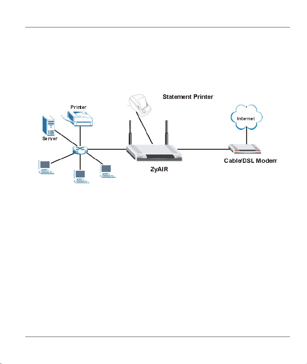
1.3.1 Internet Access for LAN Networks
With a broadband service account set up, the ZyAIR allows the attached computers to enjoy high speed
Internet access.
Figure 1-1 Application: Internet Access for LAN Networks
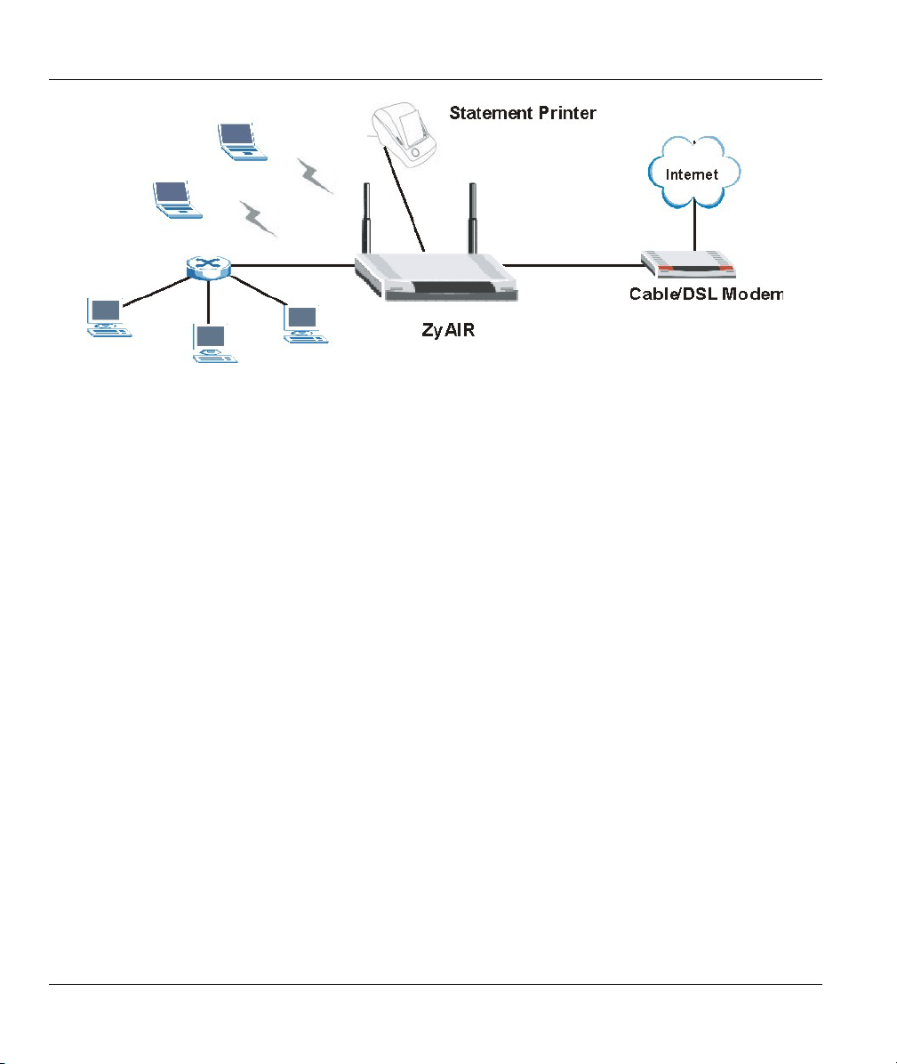
1.3.2 Internet Access in Public Areas
In public areas, such as a hotel, the ZyAIR provides high speed Internet access to subscribers. Account
billing and authentication can be done using the built-in billing function and local subscriber database.
The ZyAIR functions as an access point (AP) to bridge the wired and the wireless network allowing
wireless stations to access the Internet through the ZyAIR.
Getting to Know Your ZyAIR 1-5
Page 24
ZyAIR B-4000 Hot Spot Gateway
Figure 1-2 Application: Internet Access in Public Areas
1-6 Getting to Know Your ZyAIR
Page 25
ZyAIR B-4000 Hot Spot Gateway
Chapter 2
The Web Configurator
This chapter introduces how to access the web configurator to perform general system
configuration.
2.1 Introducing the Web Configurator
The web configurator is best viewed with Internet Explorer (version 4.0 or above) or Netscape Navigator
(version 6.0 or above). Your browser must have JavaScript support enabled.
2.2 Accessing the Web Configurator
Follow the steps below to access the web configurator.
The ZyAIR allows only one web configurator session at any one time.
Step 1. Make sure your ZyAIR is properly connected (refer to instructions in the Quick Installation
Guide on hardware installtion and connections).
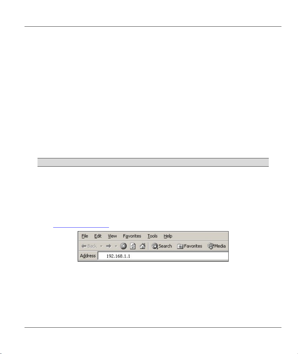
Step 2. Launch your web browser and type the WAN or LAN IP address of the ZyAIR as the web
address (it is recommended that you connect your computer to the LAN and use the LAN IP
address for initial configuration). 192.168.1.1 is the default IP address for the LAN port.
If you are using a different port number (between 8000 and 8099) for the web server, you must
also append the port number to the LAN IP address seperated with a colon “:”, for example,
http://192.168.1.1:8080
.
Figure 2-1 Entering ZyAIR IP Address in Internet Explorer
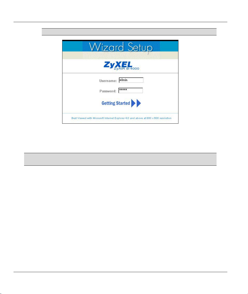
Step 3. A login screen displays. Type “admin” (default) as the user name and "1234" (default) as the
password and click Getting Started ►►.
The Web Configurator 2-1
Page 26
ZyAIR B-4000 Hot Spot Gateway
The user name and password are case sensitive.
Figure 2-2 Web Configurator: Login
Step 4. You should see the first screen of the Wizard Setup. Refer to the Quick Installation Guide for
more information on configuring the Wizard Setup screens.
The ZyAIR automatically logs you out if there is no activity for longer than 20
minutes after you log in. If this happens, simply log back in again.
2.3 Wizard Setup Screens
The Wizard Setup screens display when you first access the ZyAIR. Refer to the Quick Installation Guide
for information on how to configure the Wizard Setup screens.
2.4 Navigating the Web Configurator
After you finish the Wizard Setup screens, the ZyAIR web configurator provides two levels of navigation:
the navigation tabs and sub-menu panels.
2.4.1 The Navigation Tabs
The navigation tabs at the top of the screen correspond to menus of screens grouped by category. Click a
navigation tab to display the tab’s sub-menu panel.
2-2 The Web Configurator
Page 27
ZyAIR B-4000 Hot Spot Gateway
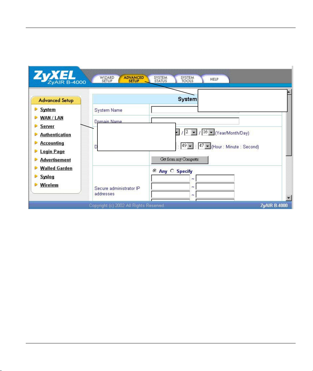
2.4.2 Sub-menu Panels
The sub-menu panel on the left of each web configurator screen provides a consistent way to access the
configuration screens in a navigation tab. Click a link to open the corresponding screen.
These are the navigation tabs.
ADVANCED SETUP is selected.
This is the sub-menu panel.
These are the Advanced
Setup tab sub-menus.
Figure 2-3 Web Configurator Navigation
2.5 Login Accounts
There are four system accounts that you can use to log in to the ZyAIR: administrator, account manager,
supervisor and super subscriber.
The administrator account allows you full access to all system configurations. The default administrator
user name is “admin” and the default password is “1234”.
The account manager account is used for proprietary subscriber account management only. No system
configuration is allowed. This account is useful for front desk personnel (such as in a hotel) for setting up
subscriber accounts without tampering with the system configuration. The account manager default user
name and password are “account”.
With the supervisor account, you can only view the system status and change the supervisor account
password. The default supervisor account user name and password are “supervisor”.
The Web Configurator 2-3
Page 28
ZyAIR B-4000 Hot Spot Gateway
Use the super subscriber account to test the Internet connection between the ZyAIR and the ISP. The
ZyAIR does not impose time limitations or charges on this account. Thus, anyone who logs in with this
account is able to gain Internet access for free. The default super subscriber user name and password are
“super”.
You can only log in using the super subscriber account in the subscriber login
screen.
2.5.1 Changing Login Account Usernames and Passwords
It is recommended you change the account passwords.
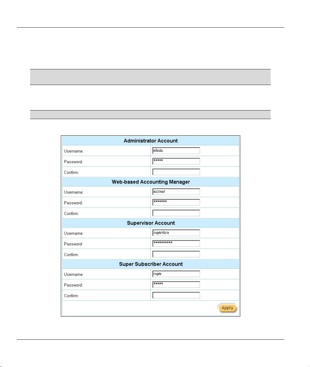
Click the SYSTEM TOOLS tab and System Account.
Figure 2-4 System Tools: System Account
2-4 The Web Configurator
Page 29

ZyAIR B-4000 Hot Spot Gateway
The account user names and passwords are case sensitive.
Table 2-1 System Tools: System Account
LABEL DESCRIPTION
Administrator Account
Username
Password Enter a new administrative account password.
Confirm Enter the new administrator password again for confirmation.
Web-based Accounting Manager
Username
Password Enter a new account manager password.
Confirm Enter the new account manager password again for confirmation.
Supervisor Account
Username
Password Enter a new supervisor password.
Confirm Enter the new supervisor password again for confirmation.
Super Subscriber Account
Enter the user name for the administrative account. The default is admin.
Enter the user name for the account manager account. The default is account.
Enter the user name for the supervisor account. The default is supervisor.
You can only log in using the super subscriber account in the subscriber login
screen.
Username
Password Enter a new super subscriber account password.
Confirm Enter the new super subscriber account password again for confirmation.
Apply
Enter the user name for the super subscriber account. The default is super.
Click Apply to save the changes back to the ZyAIR.
2.6 Methods of Restoring Factory-Defaults
There are two methods you can use to erase the current configuration and restore factory defaults.
The Web Configurator 2-5
Page 30
ZyAIR B-4000 Hot Spot Gateway
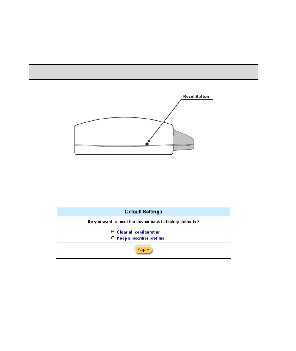
2.6.1 The Reset Button
The reset button is located on the left side panel. Use a pointed object to press this button in once to reset
the ZyAIR back to the factory defaults.
All of your custom configuration including the local subscriber database will be
erased.
Figure 2-5 Side Panel
2.6.2 Web Configurator
To reset the ZyAIR back to the factory defaults, click the SYSTEM TOOLS tab and Default Settings to
display the screen as shown next.
Figure 2-6 Default Settings
The following table describes the labels in this screen.
2-6 The Web Configurator
Page 31

ZyAIR B-4000 Hot Spot Gateway
Table 2-2 Default Settings
LABEL DESCRIPTION
Clear all
configuration
Keep subscriber
profile
Apply
Select this option to reset system configuration back to the factory defaults and erase
all custom configuration (including as subscriber account information).
Select this option to reset the system configuration back to the factory default but
retain subscriber account information. All other custom configuration is erased.
Click Apply to reset the ZyAIR.
2.7 Restarting the ZyAIR
You must restart the ZyAIR every time you change the system IP address or upload a firmware or
configuration file.
Click the SYSTEM TOOLS tab, Restart and then Apply.
Figure 2-7 Restart
When the ZyAIR restarts, all connections will be terminated. Subscribers need to
log in again.
2.8 Logging Out of the Web Configurator
Click the SYSTEM TOOLS tab, Logout and Apply to exit from the web configurator.
Figure 2-8 Logging Out
The Web Configurator 2-7
Page 32

Page 33

ZyAIR B-4000 Hot Spot Gateway
Chapter 3
General System Setup
This chapter describes how to configure the System and LAN/WAN advanced setup screens.
3.1 General System Settings
Click the ADVANCED SETUP tab and then System to open this screen.
The Domain Name entry is what is propagated to the DHCP clients on the LAN. If you leave this blank,
the domain name obtained by a DHCP server is used. While you must enter the host name (System Name)
on each individual computer, the domain name can be assigned from the ZyAIR via DHCP.
Figure 3-1 System
The following table describes the labels in this screen.
General System Setup 3-1
Page 34

ZyAIR B-4000 Hot Spot Gateway
Table 3-1 System
LABEL DESCRIPTION
System Name Enter a descriptive name (up to 40 characters) for identification purposes.
Domain Name Enter the domain name (if you know it) here. If you leave this field blank, the
ZyAIR may obtain a domain name from a DHCP server.
The domain name entered by you is given priority over the DHCP server assigned
domain name.
Date/Time Set the system date and time by selecting the appropriate choices from the drop-
down list boxes.
Click Get from my Computer to set the time and date on the ZyAIR to be the
same as the management computer.
Secure administrator
IP addresses
Multicast Pass
Through
Allow remote user to
ping the device
SSL Certificate Secure Socket Layer (SSL) security allows you to create a secure connection
Apply
Select Any to use any computer to access the web configurator on the ZyAIR.
Select Specify and then enter the IP address(es) or ranges of IP addresses of the
computer(s) that are allowed to log in to configure the ZyAIR.
Select Enable to allow multicast traffic to pass through the ZyAIR. This may affect
your network performance.
Select Disable to prevent any multicast traffic from passing through the ZyAIR.
This is the default setting.
Select Enable to respond to Ping requests.
Select Disable to not respond to Ping requests.
between the ZyAIR and the client computer(s).
Select Default to use the default system-generated SSL certificate.
Select Customer Certificate to use a certificate obtained from a certificate
authority.
Refer to the SSL (Secure Socket Layer) Security chapter for more information.
Click Apply to save the changes.
3-2 The Web Configurator
Page 35

ZyAIR B-4000 Hot Spot Gateway
Chapter 4
WAN, LAN and Server Setup
This chapter shows you how to configure LAN and WAN ports and server settings.
4.1 Factory Ethernet Defaults
The Ethernet parameters of the ZyAIR are preset to the following values:
• Dynamic WAN IP address.
• LAN IP address of 192.168.1.1 with subnet mask of 255.255.255.0
• DHCP server enabled on the LAN with a 252 client IP address pool starting from 192.168.1.2.
These parameters should work for the majority of installations. If you wish to change the factory defaults or
to learn more about TCP/IP, please read on.
4.2 LANs and WANs
A LAN (Local Area Network) is a computer network limited to the immediate area, usually the same
building or floor of a building. A WAN (Wide Area Network), on the other hand, is an outside connection
to another network or the Internet.
4.3 IP Address Assignment
A static IP is a fixed IP that the ZyAIR obtains from a DHCP server on a network. A dynamic IP is not
fixed; the DHCP server provides an IP address to the ZyAIR each time it connects to the network. When an
Ethernet device is configured to obtain a dynamic IP address from a DHCP server, it is known as a DHCP
client.
4.4 DHCP Configuration
DHCP (Dynamic Host Configuration Protocol) allows the individual clients (Ethernet device) to obtain the
TCP/IP configuration at start-up from a centralized DHCP server. The ZyAIR has built-in DHCP server
capability, which means it can assign IP addresses, an IP default gateway and DNS servers to computer
systems that support the DHCP client when this feature is activated. The ZyAIR can also act as a surrogate
DHCP server where it relays IP address assignment from the actual DHCP server to the clients.
WAN, LAN and Server Setup 4-1
Page 36

ZyAIR B-4000 Hot Spot Gateway
4.4.1 IP Address and Subnet Mask
Like houses on a street that share a common street name, the computers on a LAN share one common
network number.
Where you obtain your network number depends on your particular situation. If the ISP or your network
administrator assigns you a block of registered IP addresses, follow their instructions in selecting the IP
addresses and the subnet mask.
The Internet Assigned Number Authority (IANA) reserved a block of addresses specifically for private use
( refer to Section 4.4.2); please do not use any other number unless you are told otherwise. Let’s say you
select 192.168.1.0 as the network number; which covers 254 individual addresses, from 192.168.1.1 to
192.168.1.254 (zero and 255 are reserved). In other words, the first three numbers specify the network
number while the last number identifies an individual computer on that network.
The subnet mask specifies the network number portion of an IP address.
4.4.2 Private IP Addresses
Every machine on the Internet must have a unique address. If your networks are isolated from the Internet,
for example, only between your two branch offices, you can assign any IP addresses to the hosts without
problems. However, the Internet Assigned Numbers Authority (IANA) has reserved the following three
blocks of IP addresses specifically for private networks:
10.0.0.0 — 10.255.255.255
172.16.0.0 — 172.31.255.255
192.168.0.0 — 192.168.255.255
You can obtain your IP address from the IANA, from an ISP or it can be assigned from a private network.
If you belong to a small organization and your Internet access is through an ISP, the ISP can provide you
with the Internet addresses for your local networks. On the other hand, if you are part of a much larger
organization, you should consult your network administrator for the appropriate IP addresses.
Regardless of your particular situation, do not create an arbitrary IP address; always follow the guidelines
above. For more information on address assignment, please refer to RFC 1597, Address Allocation for
Private Internets and RFC 1466, Guidelines for Management of IP Address Space.
4.5 DNS Server Address
DNS (Domain Name System) is for mapping a domain name to its corresponding IP address and vice
versa, for example, the IP address of www.zyxel.com is 204.217.0.2. The DNS server is extremely
important because without it, you must know the IP address of a machine before you can access it. The
4-2 WAN, LAN and Server Setup
Page 37

ZyAIR B-4000 Hot Spot Gateway
DNS server addresses that you enter in the DHCP setup are passed to the client machines along with the
assigned IP address and subnet mask.
There are two ways that an ISP disseminates the DNS server addresses. The first is for an ISP to tell a
customer the DNS server addresses, usually in the form of an information sheet, when s/he signs up. The
second is to obtain the DNS server information automatically when a computer is set as a DHCP client.
4.6 PPPoE
Point-to-Point Protocol over Ethernet (PPPoE) functions as a dial-up connection. PPPoE is an IETF
(Internet Engineering Task Force) draft standard specifying how a host personal computer interacts with a
broadband modem (for example xDSL, cable, wireless, etc.) to achieve access to high-speed data networks.
It preserves the existing Microsoft Dial-Up Networking experience and requires no new learning or
procedures.
For the service provider, PPPoE offers an access and authentication method that works with existing access
control systems (for instance, RADIUS). For the user, PPPoE provides a login and authentication method
that the existing Microsoft Dial-Up Networking software can activate, and therefore requires no new
learning or procedures for Windows users.
One of the benefits of PPPoE is the ability to let end users access one of multiple network services, a
function known as dynamic service selection. This enables the service provider to easily create and offer
new IP services for specific users.
Operationally, PPPoE saves significant effort for both the subscriber and the ISP/carrier, as it requires no
specific configuration of the broadband modem at the subscriber’s site.
By implementing PPPoE directly on the ZyAIR (rather than individual computers), the computers on the
LAN do not need PPPoE software installed, since the ZyAIR does that part of the task. Furthermore, with
NAT, all of the LAN's computers will have Internet access.
4.6.1 PPP MTU
A maximum transmission unit (MTU) is the largest size packet or frame, specified in octets (eight-bit
bytes) that can be sent in a packet- or frame-based network. The Transmission Control Protocol (TCP) uses
the MTU to determine the maximum size of each packet in any transmission. Too large an MTU size may
mean retransmissions if the packet encounters a router that can't handle that large a packet. Too small an
MTU size means relatively more header overhead and more acknowledgements that have to be sent and
handled.
4.6.2 TCP MSS
WAN, LAN and Server Setup 4-3
Page 38

ZyAIR B-4000 Hot Spot Gateway
The maximum segment size (MSS) is the largest amount of data, specified in bytes, that a computer or
communications device can handle in a single, unfragmented piece. For optimum communications, the
number of bytes in the data segment and the header must add up to less than the number of bytes in the
maximum transmission unit (MTU).
4.7 PPTP
Point-to-Point Tunneling Protocol (PPTP) is a network protocol that enables transfers of data from a remote
client to a private server, creating a Virtual Private Network (VPN) using TCP/IP-based networks.
PPTP supports on-demand, multi-protocol, and virtual private networking over public networks, such as the
Internet.
4.8 Configuring the WAN and LAN Settings
To configure the LAN and WAN settings on the ZyAIR, click the ADVANCED SETUP tab and
LAN/WAN to display the screen as shown. The WAN/LAN screen varies depending on the WAN Port
Mode setting.
Figure 4-1 WAN/LAN
The following table describes the labels in this screen.
4-4 WAN, LAN and Server Setup
Page 39

ZyAIR B-4000 Hot Spot Gateway
Table 4-1 WAN/LAN
LABEL DESCRIPTION
LAN
IP Address Enter the LAN IP address of the ZyAIR in dotted decimal notation. The default is
192.168.1.1.
Subnet Mask Enter the LAN subnet mask in dotted decimal notation. The default is
255.255.255.0.
WAN MAC Address
WAN Port Mode
DHCP Client Select this option to set the ZyAIR to act as a DHCP client on the WAN. The
Static IP Settings Select this option to set the ZyAIR to use a static (or fixed) IP address.
IP Address Enter the static IP address in dotted decimal notation.
Subnet Mask Enter the subnet mask in dotted decimal notation.
Default IP Gateway Enter the IP address of the default gateway device.
Primary/Secondary
DNS Server
PPPoE
Username Enter the user name exactly as your ISP assigned. If assigned a name in the
Password Enter the password associated with the user name above.
PPP MTU Setting Enter the MTU (Maximum Transfer Unit) size.
TCP MSS Setting Enter the MSS (Maximum Segment Size) size.
Service Name Enter the name of your PPPoE service.
Connect on Demand Select this option when you don’t want the connection up all the time and specify
Select Default to use the factory assigned MAC address.
If your ISP requires MAC address authentication, select Change to and enter the
MAC address of a computer on the LAN in the fields provided.
ZyAIR obtains TCP/IP information (IP address, DNS server information, etc.)
from a DHCP server. This is the default setting.
Enter the IP addresses of the primary and/or secondary DNS servers.
Select this option to activate PPPoE support. Refer to Section 4.6 for more
information.
form user@domain
components exactly as given.
an idle timeout in the Max Idle Time field. This is the default setting with an idle
timeout of 10 minutes.
where domain identifies a service name, then enter both
WAN, LAN and Server Setup 4-5
Page 40

ZyAIR B-4000 Hot Spot Gateway
Table 4-1 WAN/LAN
LABEL DESCRIPTION
Keep Alive Select this option when you want the Internet connection up all the time and
specify a redial period in the Redial Period field. When disconnected, the ZyAIR
will attempt to bring up the connection after the redial period.
PPTP
My IP Address Enter the IP address assigned to you.
My Subnet Mask Enter the subnet mask assigned to you.
Gateway IP Address Enter the IP address of the gateway device.
PPTP Server IP
Address
Username Enter the user name exactly as your ISP assigned. If assigned a name in the
Password Enter the password associated with the user name above.
PPP MTU Setting Enter the MTU (Maximum Transfer Unit) size.
TCP MSS Setting Enter the MSS (Maximum Segment Size) size.
Connections ID/Name Enter your identification name of the PPTP server assigned to you by the ISP.
Connect on Demand Select this option when you don’t want the connection up all the time and specify
Keep Alive Select this option when you want the Internet connection up all the time and
Apply
Select this option to activate PPTP support. Refer to Section 4.7 for more
information.
Enter the IP address of your ISP’s PPTP server.
form user@domain
components exactly as given.
an idle timeout in the Max Idle Time field. This is the default setting with an idle
timeout of 10 minutes.
specify a redial period in the Redial Period field. When disconnected, the ZyAIR
will attempt to bring up the connection after the redial period.
Click Apply to save the changes.
where domain identifies a service name, then enter both
4.9 Server Configuration
Use the Server screen to set the embedded web server, the LAN DHCP server and specify the e-mil server
for e-mail redirection on the ZyAIR.
Click the ADVANCED SETUP and Server to display the screen as shown next.
4-6 WAN, LAN and Server Setup
Page 41

Figure 4-2 Server
The following table describes the fields in this screen.
ZyAIR B-4000 Hot Spot Gateway
Table 4-2 Server
LABEL DESCRIPTION
Web Server
Web Server Port Specify the port number of the embedded web server on the ZyAIR for accessing
the web configurator. The default port number is 80.
Enter a number between 8010 and 8060 to access the web configurator behind a
NAT-enabled network.
If you enter a number between 8000 and 8099, you need to append the port
number to the WAN or LAN port IP address to access the web configurator. For
example, if you enter “8010” as the web server port number, then you must enter
“http://www.192.168.1.1:8010” where 192.168.1.1 is the WAN or LAN port IP
address.
WAN, LAN and Server Setup 4-7
Page 42

ZyAIR B-4000 Hot Spot Gateway
Table 4-2 Server
LABEL DESCRIPTION
SSL Security Secure Socket Layer (SSL) security allows you to create a secure connection
between the ZyAIR and the client computer(s). Refer to the SSL (Secure Socket
Layer) Security chapter for more information.
Select this check box to activate SSL security.
DHCP Server
Select the DHCP mode on the LAN.
DHCP Disable Select this option to disable DHCP server on the LAN.
DHCP Relay Select this option to set the ZyAIR to forward network configuration requests to a
DHCP server on the LAN network. Then configure the DHCP Server IP Address
field.
DHCP Server IP
Address
DHCP Server (Default) Select this option to set the ZyAIR to assign network information (IP address, DNS
DHCP Pool Start IP
Address
DHCP Pool Size This field specifies the size or count of the IP address pool. Enter a number not
Lease Duration Specify the time (in minutes between 1 and 71582788) a DHCP client is allowed to
Primary/Secondary
DNS IP Address
If you select DHCP Relay, enter the IP address of the real DHCP server.
information etc.) to Ethernet device(s) connected to the LAN port(s). This is the
default setting.
Enter the first of the continuous addresses in the IP address pool.
The default is 192.168.1.2.
greater than 512. The default is 253.
use an assigned IP address. When the lease time expires, the DHCP client is
given a new, unused IP address.
Enter the IP address of the DNS server(s) in the Primary DNS IP Address and/or
Secondary DNS IP Address fields.
You must specify a DNS server.
E-mail Server Redirect Specify the IP address or the domain name of the e-mail server to which the
ZyAIR forwards e-mail.
SMTP Port Enter the port number (25, or between 2500 and 2599) for the mail server. The
default is 25.
Apply
Click Apply to save the settings.
4-8 WAN, LAN and Server Setup
Page 43

Subscriber Account Management
PPaarrtt IIII::
Subscriber Account Management
This part covers the ADVANCED SETUP tab’s Authentication, Accounting and Login screens.
II
Page 44

Page 45

ZyAIR B-4000 Hot Spot Gateway
Chapter 5
Authentication
This chapter shows you how to set up subscriber authentication on the ZyAIR.
5.1 About the Built-in Authentication
You can use the built-in subscriber database to manage the subscribers. The ZyAIR also provides a simple,
built-in billing mechanism to set up accounting information without using an accounting software or an
accounting server (such as RADIUS).
5.2 Authentication Settings
Click the ADVANCED SETUP tab and Authentication to display the screen as shown next.
Figure 5-1 System Settings: Authentication
The following table describes the labels in this screen.
Table 5-1 System Settings: Authentication
LABEL DESCRIPTION
No
Authentication
Built-in
Authentication
Authentication 5-1
Select this option to disable subscriber authentication. Subscribers can access the
Internet without entering user names and passwords. This is the default setting.
Select this option to authenticate the subscribers using the local subscriber database.
When you select this option, you must also configure the
Accounting screen.
Page 46

ZyAIR B-4000 Hot Spot Gateway
Table 5-1 System Settings: Authentication
LABEL DESCRIPTION
SSL Login Page
Security
Apply
Select Enable to activate SSL security upon accessing the login screen so that user
names and passwords are encrypted before being transmitted to the ZyAIR.
Select Disable to de-activate SSL security for the subscriber login screen.
Refer to the SSL (Secure Socket Layer) Security chapter for more information.
Click Apply to save the changes.
5-2 Authentication
Page 47

ZyAIR B-4000 Hot Spot Gateway
Chapter 6
Accounting
This chapter shows you how to set up and manage subscriber accounts.
6.1 About Subscriber Accounts
Once the time allocated to a dynamic account is used up or a dynamic account remains un-used after the
expiration time, the account is deleted from the account list. Accounts are automatically generated either by
pressing the connected exclusive printer’s button or using the web configurator (the Account Generator
Panel screen).
6.1.1 Time-to-finish Accounting Method
The time-to-finish accounting method is good for one-time logins. Once a subscriber logs in, the ZyAIR
stores the MAC address of the subscriber’s computer for the duration of the time allocated. Thus the
subscriber does not have to enter the user name and password again for re-login within the allocated time.
Once activated, the subscriber account is valid until the allocated time is reached even if the subscriber
disconnects Internet access for a certain period within the allocated time. For example, Joe purchases a onehour time-to-finish account. He starts using the Internet for the first 20 minutes and then disconnects his
Internet access to go to a 20-minute meeting. After the meeting, he only has 20 minutes left on his account.
6.2 Accounting Settings
Click the ADVANCED SETUP tab and Accounting to display the screen as shown next.
Accounting 6-1
Page 48

ZyAIR B-4000 Hot Spot Gateway
Figure 6-1 Accounting
6-2 Accounting
Page 49

The following table describes the labels in this screen.
Table 6-1 Accounting
LABEL DESCRIPTION
ZyAIR B-4000 Hot Spot Gateway
Preview/Operate
No. This read-only field displays the button index number (Button 1..4). The button numbers
Button name A button is a subscriber “profile” defining maximum Internet access time and charge per
Account
Usage Time
Charge
Decimals Define the number of decimal places allowed (up to 3) for the total amount charged that
Account Setting
Expire Time Specify the number of hours (1 to 168) to wait before the ZyAIR deletes an inactive
Click Preview/Operate to open the Account Generator Panel (see Figure 6-3).
correspond to the buttons displayed in the Account Generator Panel (see Figure 6-3).
The button 1 settings will apply to the “exclusive printer” button setting.
time unit. The button 1 settings also apply to the button on the “exclusive printer”. The
button numbers correspond to the buttons displayed in the Account Generator Panel.
Type up to 12 characters to specify the names that appear on the buttons.
The defaults are 30 minutes, 1 hour, 2 hours and 3 hours.
Select a time period (minutes, hours, or days) and enter the time unit in the field
provided to define each “profile’s” maximum Internet access time. The defaults are
Button 1 30 minutes, Button 2 1hour, Button 3 2hours and Button 4 3hours.
Define each “profile’s” charge, up to 999999, per time unit (configured in the Account
Usage Time field). The default is 0.00.
appears in the subscriber’s statement in the Decimals field.
account (default 12).
Printout Setting
Number of copies
to print
Customize Printout Label
Title Enter a title (up to 24 characters) for the printout.
Select how many copies of subscriber statements you want to print (1 is the default).
Accounting 6-3
Page 50

ZyAIR B-4000 Hot Spot Gateway
Table 6-1 Accounting
LABEL DESCRIPTION
Username Enter the label name for the field that displays the account username.
Password Enter the label name for the field that displays the account password.
Usage Time Type a label name for the maximum time allowed for a subscriber to access the Internet
via the ZyAIR.
Price Select this check box and type a label for the field displaying the total charge to the
subscriber in the statement.
Currency Type a currency prefix that displays before the total charge amount in the statement.
ESSID Type a label name for the field displaying the wireless LAN’s Extended Service Set
Identifier (ESSID).
WEP
Time Select this check box to display the time an account is created and then select date and
Ending Select this check box to display (in the statement) the ending subscription validity date
Expiration Time Select this check box to display (in the statement) the ending subscription validity date
Serial Number Select this check box to generate and display (in the statement) a number for each
Preview
Apply
Type a label name for the field displaying the Wired Equivalent Privacy (WEP
Encryption) key.
time formats from the drop-down list boxes.
and time and then select the date and time formats from the drop-down list boxes.
and time and then select the date and time formats from the drop-down list boxes.
subscriber account that you use the ZyAIR to generate.
Click Preview to display a sample of the statement layout in a new window (see Figure
6-2). If you modify the settings on this page, click Apply before you click Preview if you
want to see how the changed settings will affect the statement layout.
Click Apply to save your settings to the ZyAIR.
The following is an example of how your custom statement printout will look. Close this window when you
are finished viewing it.
6-4 Accounting
Page 51

ZyAIR B-4000 Hot Spot Gateway
Figure 6-2 Printout Label Preview Example
6.3 Creating Accounts
There are two ways to create subscriber accounts: using the Account Generator Panel screen in the web
configurator or using the exclusive printer.
6.3.1 Creating Accounts in the Web Configurator
To create subscriber accounts, click Preview/Operate in the Accounting screen to display the Account
Generator Panel screen shown next.
Figure 6-3 Account Generator Panel
Accounting 6-5
Page 52

ZyAIR B-4000 Hot Spot Gateway
The settings for the first button apply to the button on the exclusive printer. 1
Click a button to generate an account based on the settings you configure for the button in the Accounting
screen. A window displays showing a printout preview of the account generated.
The following figure shows an example.
Figure 6-4 Account Information Printout Example
6.3.2 Using the Exclusive Printer to Create and Print Subscriber
Statements
Follow the steps below to setup and create subscriber accounts and print subscriber statements using an
external statement printer.
Step 1. Make sure that the printer’s is connected to the appropriate power and the ZyAIR, and that there
is printing paper in the statement printer. Refer to the printer’s User’s Guide for details.
Step 2. Press the button on the Statement Printer. The ZyAIR generates a dynamic account and the
printer prints the subscriber’s statement. Refer to Figure 6-4 for a printout example.
1
The web-based account generator and the exclusive printer do not function together at the time of writing.
6-6 Accounting
Page 53

ZyAIR B-4000 Hot Spot Gateway
The settings of the button on the statement printer correspond to the first button
in the Account Operator Panel screen. Refer to Figure 6-3.
Refer to section 6.2 to configure the printout page.
6.4 Viewing the Account List
Do one of the following to view the account list.
• From the Account Generator Panel screen (refer to Figure 6-3) and click View Account List.
• From the SYSTEM STATUS sub-menus, click Account List.
Figure 6-5 Account List
The following table describes the labels in this screen.
Table 6-2 Account List
LABEL DESCRIPTION
Refresh
Accounting 6-7
Click Refresh to update this screen.
Page 54

ZyAIR B-4000 Hot Spot Gateway
Table 6-2 Account List
LABEL DESCRIPTION
NO This field displays the index number of an entry. The maximum number of subscriber
account entries is 512.
Status
Username This field displays the account user name. Click the heading to sort the entries in
Usage Time This field displays the amount of time the subscriber has purchased. Click the heading to
Create Time This field displays when the account was created (in yyyy/mm/dd HH/mm/ss format). Click
Login Time This field displays when the subscriber logged in to use the account (in yyyy/mm/dd
Expire Time This field displays when the subscriber’s account becomes invalid (in yyyy/mm/dd
Delete All
Delete
Go .. page Select a page number from the drop-down list box to display the selected page.
First
Previous
Next
End
This field displays IN-Used when the account is currently in use. Otherwise it displays UN-
Used.
ascending or descending order based on this column.
sort the entries in ascending or descending order based on this column.
the heading to sort the entries in ascending or descending order based on this column.
HH/mm/ss format). Click the heading to sort the entries in ascending or descending order
based on this column.
HH/mm/ss format).
When the subscriber has already logged into the account, this field displays the time until
which the subscriber can continue to use the account to access the Internet. When the
subscriber has not yet logged into the account, this field displays the time that the account
expires if the subscriber does not log into it. Click the heading to sort the entries in
ascending or descending order based on this column.
Click Delete All to remove all accounts.
Click Delete to remove the selected account.
Click First to go to the first page.
Click Previous to return to the previous page.
Click Next to go to the next page.
Click End to go to the last page.
Refer to the Subscriber Login appendix for more information on logging in as a subscriber.
6-8 Accounting
Page 55

ZyAIR B-4000 Hot Spot Gateway
Chapter 7
Subscriber Login Screen
This chapter shows you how to customize the subscriber login screen when subscriber control is
activated.
7.1 About the Subscriber Login Screen
When subscriber authentication is activated in the Authentication screen, the subscriber login screen is the
first screen that all subscribers see when trying to access the Internet. You can configure walled garden web
addresses for web sites that all subscribers are allowed to access without logging in (refer to the chapter on
advertisement links and walled garden).
The ZyAIR provides different formats in which you can customize the login screen: Standard, Redirect,
Advanced and Frame.
7.2 Customizing the Subscriber Login Screen
To customize the subscriber login screen, click the ADVANCED SETUP tab and Login Page to display
the screen as shown next.
Subscriber Login Screen 7-1
Page 56

ZyAIR B-4000 Hot Spot Gateway
Figure 7-1 Login Page
7.2.1 Standard Subscriber Login Screen
The standard subscriber login screen is the ZyAIR’s pre-configured, default simple login screen. In Login
Screen, select Standard. The following figure shows an example of what a subscriber sees when logging
in.
Figure 7-2 Subscriber Login Screen Example: Standard
7-2 Subscriber Login Screen
Page 57

ZyAIR B-4000 Hot Spot Gateway
7.2.2 Redirect Subscriber Login Screen
You can set the ZyAIR to redirect the subscribers to another login screen.
In the Login Screen Configuration screen, select Redirect.
Figure 7-3 Subscriber Login Screen: Redirect
The following table describes the related labels.
Table 7-1 Subscriber Login Screen: Redirect
LABEL DESCRIPTION
Redirect Select this option to direct the subscriber to another login screen.
Redirect Login
Page URL Link
Code
Specify the web site address to which the ZyAIR directs the subscribers for logins.
Click Code to display the source code of the web page you specify above (see
Figure 7-4).
Subscriber Login Screen 7-3
Page 58

ZyAIR B-4000 Hot Spot Gateway
Figure 7-4 Subscriber Login Screen: Redirect Code
7.2.3 Advanced Subscriber Login Screen
Use the Advanced login screen option to customize a login screen where you can create a welcome slogan
and add advertising information.
7-4 Subscriber Login Screen
Page 59

Figure 7-5 Subscriber Login Screen: Advanced
The following table describes the related labels.
Table 7-2 Subscriber Login Screen: Advanced
LABEL DESCRIPTION
ZyAIR B-4000 Hot Spot Gateway
Advanced Select this option to set the ZyAIR to display the advanced subscriber login
screen.
Welcome Slogan Enter a welcome message (up to 80 characters long) in the text box provided.
Page Background
Article Enter a block of text (up to 1024 characters long) in the text box. This is useful for
Article Text Color
Information Enter information such address and telephone or fax numbers in the text box
Select None to set the background color of the login screen to white (the default).
Select Background Color to set the color of the login screen background to the
color specified, for example, enter ‘000000’ for black. Click View Color Grid to
display a list of web-friendly colors and corresponding hexadecimal values.
advertisements or announcements.
Select None to set the article text color of the login screen to white (the default).
Select and set the color of the article text block background to the color specified,
for example, enter ‘000000’ for black. Click View Color Grid to display a list of
web-friendly colors and corresponding hexadecimal values.
provided. Up to 80 characters allowed.
Subscriber Login Screen 7-5
Page 60

ZyAIR B-4000 Hot Spot Gateway
Table 7-2 Subscriber Login Screen: Advanced
LABEL DESCRIPTION
Comments Enter any comments (up to 80 characters long) in the text box provided.
The web-friendly color sets are displayed in the figure shown.
Figure 7-6 Subscriber Login Screen: Color Grid
The following figure shows an advanced subscriber login screen example.
7-6 Subscriber Login Screen
Page 61

Figure 7-7 Subscriber Login Screen Example: Advanced
7.2.4 Framed Subscriber Login Screen
ZyAIR B-4000 Hot Spot Gateway
Welcome Slogan
Article
Information
Comment
The Frame login screen splits the login screen into two frames: top and bottom. You can specify a web site
to be displayed in the top frame with the user name and password prompt displayed in the bottom frame.
The frame login screen is useful for you to link to a web site (such as the company web site) as your
welcome screen. In addition, you can externally design a web page with images and/or advanced
multimedia features.
Figure 7-8 Subscriber Login Screen: Frame
The following table describes the related labels.
Subscriber Login Screen 7-7
Page 62

ZyAIR B-4000 Hot Spot Gateway
Table 7-3 Subscriber Login Screen: Frame
LABEL DESCRIPTION
Frame Select this option to configure and set the ZyAIR to display the subscriber login screen
in two frames.
TOP Frame
Bottom Frame
Background
Color
Enter a web site address in the URL Link field, for example, http://www.zyxel.com.
Specify the color of the frame background. For example, enter ‘000000’ for black. Click
View Color Grid to display a list of web-friendly color and corresponding hexadecimal
values. The default is white (“FFFFFF”).
The following figure shows a framed subscriber login screen example.
Figure 7-9 Subscriber Login Screen Example: Frame
7-8 Subscriber Login Screen
Page 63

Advanced Subscriber Account Management
PPaarrtt IIIIII::
Advanced Subscriber Account Management
This part covers the ADVANCED SETUP tab’s Advertisement, Walled Garden, Syslog and
Wireless screens.
III
Page 64

Page 65

ZyAIR B-4000 Hot Spot Gateway
Chapter 8
Advertisement Links and Walled Garden
This chapter shows you how to set advertisement links and create walled garden web sites.
8.1 Advertisement Links and Walled Garden Overview
When you enable subscriber authentication in the Authentication screen, you can set the ZyAIR to display
advertisement links or activate the walled garden feature for generating on-line advertising revenues.
8.2 Advertisement Links
You can set the ZyAIR to display an advertisement web page as the first web page whenever the subscriber
connects to the Internet. Click ADVANCED SETUP and Advertisement to display the screen as shown
next.
Figure 8-1 Advertisement
Advertisement Links and Walled Garden 8-1
Page 66

ZyAIR B-4000 Spot Gateway
The following table describes the labels in this screen.
Table 8-1 Advertisement
LABEL DESCRIPTION
Frequency
Select One Time Only to display an advertisement web site in an active browser
window once after a subscriber logs in successfully.
Select Every … Min(s) to display an advertisement web site in an active browser
window once every time period specified (in minutes) after a subscriber logs in
successfully.
The advertisement links are displayed randomly one at a time.
URL Link 1 .. 10 Enter the web site addresses in the fields provided.
Apply
Click Apply to save the changes.
8.3 Walled Garden
A subscriber must log in before the ZyAIR allows the subscriber access to the Internet. However, with a
walled garden, you can define a web site address(es) which all subscribers can access without logging in.
Click ADVANCED SETUP and then Walled Garden to display the screen as shown.
8-2 Advertisement Links and Walled Garden
Page 67

ZyAIR B-4000 Hot Spot Gateway
Figure 8-2 Walled Garden
The following table describes the labels in this screen.
Advertisement Links and Walled Garden 8-3
Page 68

ZyAIR B-4000 Spot Gateway
Table 8-2 Walled Garden
LABEL DESCRIPTION
Link 1 … 10
Apply
In the Name field, enter a descriptive name (up to 80 characters) for the walled garden
link to be displayed in the web browser.
In the URL field, enter the web site address (up to 200 characters) of the web site.
See the chapter on login setup for a sample display of the login screen.
Click Apply to save the changes.
8.3.1 Walled Garden Login Example
The following figure shows the subscriber login screen with four walled garden links (the links are named
Walled Garden Link 1 through 4 for demonstration purposes, see Table 8-2 to configure your own custom
link names).
Figure 8-3 Walled Garden Login Example
8-4 Advertisement Links and Walled Garden
Page 69

ZyAIR B-4000 Hot Spot Gateway
Chapter 9
Syslog
This chapter shows you how to configure syslog on the ZyAIR.
9.1 Syslog Configuration
Use the Syslog Configuration screen to configure to where the ZyAIR is to send logs; which logs the
ZyAIR is to send and the schedule for when the ZyAIR is to send the logs.
To configure the syslog settings, click ADVANCED SETUP, Syslog to display the screen as shown next.
Syslog 9-1
Page 70

ZyAIR B-4000 Spot Gateway
Figure 9-1 Syslog Configuration
9-2 Syslog
Page 71

ZyAIR B-4000 Hot Spot Gateway
The following table describes the labels in this screen.
Table 9-1 Syslog Configuration
LABEL DESCRIPTION
Syslog
Syslog Server
Syslog on LAN Select this check box to specify a syslog server on the LAN.
Server IP Address Enter the IP address (in dotted decimal notation) of the syslog server on the LAN.
Server MAC Address Enter the MAC address of the syslog server on the LAN.
Syslog on WAN Select this check box to specify a syslog server on the WAN.
Server 1 IP Address Enter the IP address of the first syslog server on the WAN in dotted decimal
Server 2 IP Address Enter the IP address of the second syslog server on the WAN in dotted decimal
Log Settings
Syslog Name This field displays the name (or type) of the syslog. Select the check box(es) to
Description This field displays a short description about the syslog.
Interval Time This field displays when or how often the ZyAIR sends the syslog. If available,
Apply
Select Enable to activate the syslog function.
Select Disable to de-activate the syslog function.
notation.
notation.
send the syslog.
enter the number of minutes the ZyAIR waits between sending the syslog.
Click Apply to save the settings.
Syslog 9-3
Page 72

Page 73

ZyAIR B-4000 Hot Spot Gateway
Chapter 10
Wireless LAN
This chapter shows you how to configure wireless LAN settings on the ZyAIR and set up WEP
encryption keys.
10.1 Wireless LAN Overview
This section introduces the wireless LAN (WLAN) and some basic scenarios.
10.1.1 IBSS
An Independent Basic Service Set (IBSS), also called an Ad-hoc network, is the simplest WLAN
configuration. An IBSS is defined as two or more computers with wireless adapters within range of each
other and can set up an independent (wireless) network without the need of an access point (AP).
Figure 10-1 IBSS (Ad-hoc) Wireless LAN
10.1.2 BSS
A Basic Service Set (BSS) is when all communications between wireless stations or between a wireless
station and a wired network client go through one access point (AP).
Intra-BSS traffic is traffic between wireless stations in the BSS.
Wireless LAN 10-1
Page 74

ZyAIR B-4000 Spot Gateway
Figure 10-2 Basic Service set
10.1.3 ESS
An Extended Service Set (ESS) consists of a series of overlapping BSSs, each containing an access point,
with each access point connected together by a wired network. This wired connection between APs is
called a Distribution System (DS). An ESSID (ESS IDentification) uniquely identifies each ESS. All
access points and their associated wireless stations within the same ESS must have the same ESSID in
order to communicate.
Figure 10-3 Extended Service Set
10-2 Wireless LAN
Page 75

ZyAIR B-4000 Hot Spot Gateway
10.2 Wireless LAN Basics
This section provides background information on Wireless LAN features.
10.2.1 Channel
The range of radio frequencies used by IEEE 802.11b wireless devices is called a “channel”. Channels
available depend on your geographical area. You may have a choice of channels (for your region) so you
should use a different channel than an adjacent AP (access point) to reduce interference. Interference
occurs when radio signals from different access points overlap causing interference and degrading
performance.
Adjacent channels partially overlap however. To avoid interference due to overlap, your AP should be on a
channel at least five channels away from a channel that an adjacent AP is using. For example, if your
region has 11 channels and an adjacent AP is using channel 1, then you need to select a channel between 6
and 11.
10.2.2 WEP Encryption
WEP (Wired Equivalent Privacy) encrypts data frames before transmitting over the wireless network. WEP
encryption scrambles the data transmitted between the wireless stations and the access points to keep
network communications private. It encrypts unicast and multicast communications in a network. Both the
wireless stations and the access points must use the same WEP key for data encryption and decryption.
WEP degrades performance.
10.2.3 RTS/CTS
A hidden node occurs when two stations are within range of the same access point, but are not within range
of each other. The following figure illustrates a hidden node. Both stations (STA) are within range of the
access point (AP) or wireless gateway, but out-of-range of each other, so they cannot “hear” each other,
that is they do not know if the channel is currently being used. Therefore, they are considered hidden from
each other.
Wireless LAN 10-3
Page 76

ZyAIR B-4000 Spot Gateway
Figure 10-4 RTS/CTS
When station A sends data to the ZyAIR, it might not know that station B is already using the channel. If
these two stations send data at the same time, collisions may occur when both sets of data arrive at the AP
at the same time, resulting in a loss of messages for both stations.
RTS/CTS is designed to prevent collisions due to hidden nodes. An RTS/CTS defines the biggest size data
frame you can send before an RTS (Request To Send)/CTS (Clear to Send) handshake is invoked.
When a data frame exceeds the RTS/CTS value you set (between 0 to 2432 bytes), the station that wants to
transmit this frame must first send an RTS (Request To Send) message to the AP for permission to send it.
The AP then responds with a CTS (Clear to Send) message to all other stations within its range to notify
them to defer their transmission. It also reserves and confirms with the requesting station the time frame for
the requested transmission.
Stations can send frames smaller than the specified RTS/CTS directly to the AP without the RTS (Request
To Send)/CTS (Clear to Send) handshake.
You should only configure RTS/CTS if the possibility of hidden nodes exists on your network and the
“cost” of resending large frames is more than the extra network overhead involved in the RTS (Request To
Send)/CTS (Clear to Send) handshake.
If the RTS/CTS value is greater than the Fragmentation Threshold value (see next), then the RTS
(Request To Send)/CTS (Clear to Send) handshake will never occur as data frames will be fragmented
before they reach RTS/CTS size.
10-4 Wireless LAN
Page 77

ZyAIR B-4000 Hot Spot Gateway
Enabling the RTS Threshold causes redundant network overhead that could
negatively affect the throughput performance instead of providing a remedy.
10.2.4 Fragmentation Threshold
A Fragmentation Threshold is the maximum data fragment size (between 256 and 2432 bytes) that can be
sent in the wireless network before the ZyAIR will fragment the packet into smaller data frames.
A large Fragmentation Threshold is recommended for networks not prone to interference while you
should set a smaller threshold for busy networks or networks that are prone to interference.
If the Fragmentation Threshold value is smaller than the RTS/CTS value (see previously) you set then
the RTS (Request To Send)/CTS (Clear to Send) handshake will never occur as data frames will be
fragmented before they reach RTS/CTS size.
10.2.5 Preamble Type
A preamble is a signal used to synchronize the transmission timing in your wireless network. There are two
preamble modes: Long and Short.
Long preamble mode allows more processing time for each transmitted data packet. Short preamble mode
allows less processing time for the transmitted data packets.
Using short preamble mode may minimize overhead and maximize network throughput. However, short
preamble mode is supported by IEEE 802.11b compliant wireless devices, thus wireless stations using short
preamble mode cannot communicate with wireless stations using the original IEEE 802.11 standard.
10.3 Wireless LAN Setup
If you are configuring the ZyAIR from a computer connected to the wireless LAN
and you change the ZyAIR’s ESSID or WEP settings, you will lose your wireless
connection when you press Apply to confirm. You must then change the wireless
settings of your computer to match the ZyAIR’s new settings.
Click ADVANCED SETUP and then WIRELESS to open the Wireless screen.
Wireless LAN 10-5
Page 78

ZyAIR B-4000 Spot Gateway
Figure 10-5 Wireless
The following table describes the general wireless LAN fields in this screen.
Table 10-1 Wireless
LABEL DESCRIPTION
ESSID (Extended Service Set IDentity) The ESSID identifies the Service Set with which a
wireless station is associated. Wireless stations associating to the access point (AP)
must have the same ESSID. Enter a descriptive name (up to 32 printable 7-bit ASCII
characters) for the wireless LAN.
If you are configuring the ZyAIR from a computer connected to the wireless LAN and you
change the ZyAIR’s ESSID or WEP settings, you will lose your wireless connection when
you click Apply. You must then change the wireless settings of your computer to match
the ZyAIR’s new settings.
Channel Select a channel from the drop-down list box depending on your particular region.
10-6 Wireless LAN
Page 79

ZyAIR B-4000 Hot Spot Gateway
Table 10-1 Wireless
LABEL DESCRIPTION
WEP
Encryption
Beacon Interval Set the number of milliseconds that should pass between sending out a beacon. Enter a
RTS Threshold Enter a value between 0 and 2442 to enable an RTS/CTS handshake to avoid
Fragmentation
Threshold
DTIM Interval This setting, always a multiple of the beacon period, determines how often the beacon
Transmission
Rates
Preamble Type
Antenna
Selection
Select Disable to allow all wireless computers to communicate with the access points
without any data encryption.
Select Mandatory to enable WEP data encryption. Then click WEP Key Setup to open a
screen where you can configure the WEP keys on the ZyAIR. Refer to Section 10.3.1.
time period between 1 and 1000. The default is 100.
retransmitting due to hidden nodes. The default is 2432.
Enter a value between 256 and 2446 to enable a fragmentation threshold. This sets the
maximum size of data fragments that can be sent. The default is 2432. Use a low setting
if there is a great deal of radio interference.
contains a delivery traffic indication message (DTIM). The DTIM tells client devices that
are set to power-save that a packet is waiting for them. The DTIM Interval’s valid range is
1 to 65535.
The basic transfer rates should be set depending on the speed of your wireless network.
The default setting is 1-2-5.5-22 (Mbps).
Select either Short Preamble or Long Preamble.
Select Left Antenna if your device has removable antennas and you install a high-gain
antenna on the connector on the left (when you look at the device's rear panel).
Select Right Antenna if your device has removable antennas and you install a high-gain
antenna on the connector on the right (when you look at the device's rear panel).
Select Diversity Antenna (default) to have the device use the antenna that receives the
best signal.
Wireless LAN 10-7
Page 80

ZyAIR B-4000 Spot Gateway
Table 10-1 Wireless
LABEL DESCRIPTION
Authentication
Method
SSID Broadcast
Default Click this button to load the factory default wireless LAN settings.
Apply
Select Open System to allow any device to authenticate and then attempt to
communicate with the ZyAIR. Using open authentication, any wireless device can
authenticate with the ZyAIR, but the device can only communicate if its WEP keys match
the ZyAIR. Devices not using WEP do not attempt to authenticate with a ZyAIR that is
using WEP. Open authentication does not rely on a RADIUS server on your network.
Select Shared Key to have the ZyAIR use shared key authentication. The ZyAIR sends
an unencrypted challenge text string to any device attempting to communicate with the
ZyAIR. The device-requesting authentication encrypts the challenge text and sends it
back to the ZyAIR. If the challenge text is encrypted correctly, the ZyAIR allows the
requesting device to authenticate. However, both the unencrypted challenge and the
encrypted challenge can be monitored; thus leaving the ZyAIR open to attack from an
intruder who calculates the WEP key by comparing the unencrypted and encrypted text
strings. Because of this weakness, shared key authentication can be less secure than
open authentication. Like open authentication, shared key authentication does not rely
on a RADIUS server on your network.
Select Both to allow subscribers to communicate with or without data encryption.
Select Enable to allow devices that do not specify an SSID (Service Set Identity) to
associate with the ZyAIR.
Select Disable to stop devices that do not specify an SSID (devices that are
"broadcasting" in search of an access point to associate with) from associating with the
ZyAIR. The SSID on the subscriber’s device must match the ZyAIR's SSID exactly.
Click Apply to save the settings.
10.3.1 Configuring WEP Keys
When you select Mandatory in the WEP Encryption field in the Wireless screen, click WEP Key
Setting to display the screen as shown.
10-8 Wireless LAN
Page 81

Figure 10-6 WEP Key Setup
The following table describes the labels in this screen.
Table 10-2 WEP Key Setup
ZyAIR B-4000 Hot Spot Gateway
LABEL DESCRIPTION
WEP Encryption
Mode
Select 64 bit, 128 bit or 256 bit for the WEP key length.
Select the type of input mode from the drop-down list box. Choices are HEX
and ASCII.
Select ASCII to enter the WEP keys as ASCII characters.
Select HEX to enter the WEP keys as hexadecimal characters.
Wireless LAN 10-9
Page 82

ZyAIR B-4000 Spot Gateway
LABEL DESCRIPTION
1 … 4 Enter the WEP keys in the fields provided and select a key as the default key to
use.
If you select 64 bit in the WEP Encryption field.
or
If you select 128 bit in the WEP Encryption field,
or
If you select 256 bit in the WEP Encryption field,
or
Table 10-2 WEP Key Setup
Enter either 10 hexadecimal digits in the range of “A-F”, “a-f” and “0-9”
(e.g. 11AA22BB33) for HEX key type
Enter 5 printable ASCII characters (case sensitive) ranging from “a-z”,
“A-Z” and “0-9” (e.g. MyKey) for ASCII key type.
Enter either 26 hexadecimal digits in the range of “A-F”, “a-f” and “0-9”
(for example, 00112233445566778899AABBCC) for HEX key type
Enter 13 printable ASCII characters (case sensitive) ranging from “a-
z”, “A-Z” and “0-9” (for example, MyKey12345678) for ASCII key type.
Enter either 58 hexadecimal digits in the range of “A-F”, “a-f” and “0-9”
for HEX key type
Enter 29 printable ASCII characters (case sensitive) ranging from “a-
z”, “A-Z” and “0-9” for ASCII key type.
ASCII WEP keys are case sensitive.
You must configure all four WEP keys the first time you
use the ZyAIR.
Apply
Click Apply to save the changes.
10-10 Wireless LAN
Page 83

System Status, System Tools and Troubleshooting
Part IV:
System Status, System Tools and Troubleshooting
This part covers the sub-menus in SYSTEM STATUS and SYSTEM TOOLS and troubleshooting.
IV
Page 84

Page 85

ZyAIR B-4000 Hot Spot Gateway
System Status
This chapter describes the screens under System Status.
11.1 About System Status
The screens in SYSTEM STATUS show the current state of the ZyAIR.
11.2 View System Information
Click SYSTEM STATUS and System to display the screen as shown next.
Chapter 11
System Status 11-1
Page 86

ZyAIR B-4000 Hot Spot Gateway
Figure 11-1 System
11-2 System Status
Page 87

ZyAIR B-4000 Hot Spot Gateway
The following table describes the labels in this screen.
Table 11-1 System
LABEL DESCRIPTION
System Status
System Name This field displays the description name of the ZyAIR for identification purposes.
Bootrom Version This field displays the version of the bootbase in the ZyAIR.
Firmware Version This field displays the version of the firmware on the ZyAIR.
Wireless Version This field displays the version of the wireless features on the ZyAIR.
Concurrent Users
Limitation
WAN MAC Address This field displays the MAC address of the ZyAIR on the WAN.
LAN MAC Address This field displays the MAC address of the ZyAIR on the LAN.
WAN IP Settings
WAN Port Mode
IP Address This field displays the IP address of the WAN port on the ZyAIR.
Subnet Mask This field displays the subnet mask of the WAN port on the ZyAIR.
Gateway IP
address
DNS
Primary DNS
Server
Secondary DNS
Server
LAN DHCP
DHCP Status This field displays the DHCP mode on the LAN.
Start IP Address This field displays the first of the continuous addresses in the IP address pool.
End IP Address This field displays the last of the continuous addresses in the IP address pool.
This field displays the maximum number of users that can connect to the ZyAIR at
the same time.
This field displays the DHCP mode of the WAN port. It displays either DHCP Client
or Static IP Setting.
This field displays the IP address of the default gateway of the WAN port on the
ZyAIR.
This field displays the IP address of the primary DNS server.
This field displays the IP address of the secondary DNS server.
System Status 11-3
Page 88

ZyAIR B-4000 Hot Spot Gateway
Table 11-1 System
LABEL DESCRIPTION
Lease Time This field displays the time period (in minutes between 1 and 71582788) during
which a DHCP client is allowed to use an assigned IP address. When the lease time
expires, the DHCP client is given a new, unused IP address.
E-mail
Server IP Address The field displays the IP address or the domain name of the SMTP server.
SSL Certification
Country This field displays the two-letter abbreviation of your country.
State This field displays the name of the state or province where your organization is
located.
Local City This field displays the name of the city your organization is located.
Organization This field displays the name of your organization.
Origination Unit This field displays additional information about your organization.
Common Name This field displays the fully qualified domain name of your web server.
Email Address This field displays your e-mail address.
11.3 Account List
Refer to the Accounting chapter for an example and explanation of the Account List screen.
11.4 Account Log
The Account Log screen displays information on the ZyAIR’s subscriber account logs.
Click SYSTEM STATUS and Current Users to display the screen as shown. Click a column heading to
sort the entries if applicable.
11-4 System Status
Page 89

Figure 11-2 Account Log
ZyAIR B-4000 Hot Spot Gateway
The following table describes the labels in this screen.
Table 2 Account Log
FIELD DESCRIPTION
Clear Log
Refresh
NO This field displays the index number of an entry. The maximum number of user account
Username This field displays the account user name. Click the heading to sort the entries in
Time Created This field displays when the account was created (in yyyy/mm/dd HH/mm/ss format).
Click Clear Log to remove all of the log entries from the ZyAIR’s memory and this
screen.
Click Refresh to update this screen.
entries is 512.
ascending or descending order based on this column.
Click the heading to sort the entries in ascending or descending order based on this
column.
System Status 11-5
Page 90

ZyAIR B-4000 Hot Spot Gateway
Table 2 Account Log
FIELD DESCRIPTION
Login Time This field displays when the subscriber logged in to use the account (in yyyy/mm/dd
HH/mm/ss format). Click the heading to sort the entries in ascending or descending
order based on this column.
Usage Time This field displays the amount of time the subscriber has purchased. Click the heading
to sort the entries in ascending or descending order based on this column.
Charge This field displays the total cost of the subscriber’s account.
Status
Go .. page Select a page number from the drop-down list box to display the selected page.
First
Previous
Next
End
This field displays IN-Used when the account is currently in use. Otherwise it displays
UN-Used.
This field displays Finished when a subscriber uses up the time allocated to an
account.
Click First to go to the first page.
Click Previous to return to the previous page.
Click Next to go to the next page.
Click End to go to the last page.
11.5 Current Users
The Current Users screen displays a list of subscribers currently logged on to the ZyAIR for Internet
access.
Click SYSTEM STATUS and Current Users to display the screen as shown. Click a column heading to
sort the entries if applicable.
Figure 11-3 Current User List
The following table describes the labels in this screen.
11-6 System Status
Page 91

ZyAIR B-4000 Hot Spot Gateway
Table 11-3 Current User List
LABEL DESCRIPTION
No This field displays the index number of the entry.
Username This field displays the user name of an account.
IP Address This field displays the IP address of a subscriber’s computer.
MAC
Address
Disconnect
This field displays the MAC address of the computer that is logged in using the account.
Click Apply to terminate the connection to the selected subscriber.
11.6 DHCP Clients
The DHCP client table shows current DHCP client information of all network clients using the DHCP
server on the ZyAIR.
Click SYSTEM STATUS and DHCP to display the screen as shown.
Figure 11-4 DHCP Clients
The following table describes the labels in this screen.
Table 11-4 DHCP Clients
LABEL DESCRIPTION
MAC Address This field displays the MAC address of the client computer.
The MAC (Media Access Control) or Ethernet address on a LAN (Local Area Network) is
unique to your computer (six pairs of hexadecimal characters).
A network interface card such as an Ethernet adapter has a hardwired address that is
assigned at the factory. This address follows an industry standard that ensures no other
adapter has a similar address.
IP Address This field displays the IP address assigned to the client computer.
System Status 11-7
Page 92

ZyAIR B-4000 Hot Spot Gateway
11.7 Session List
To display a list of incoming and outgoing packet information, click SYSTEM STATUS and Session List.
Figure 11-5 Session List
The following table describes the fields in this screen.
Table 11-5 Session List
LABEL DESCRIPTION
Go .. page Select a page number from the drop-down list box to display the selected page.
First
Previous
Next
End
No This field displays the index number of an entry.
TCP/UDP
IP Client This field displays the IP address of the client computer.
Port Client This field displays the port number through which the client computer transmits the traffic.
Port Fake This field displays the NAT port to and from which the ZyAIR maps the session’s traffic.
Click First to go to the first page.
Click Previous to return to the previous page.
Click Next to go to the next page.
Click End to go to the last page.
This field displays the type of traffic (TCP or UDP).
11-8 System Status
Page 93

ZyAIR B-4000 Hot Spot Gateway
Table 11-5 Session List
LABEL DESCRIPTION
Remote
Port
Idle This field displays how many seconds are left before the session times out if there is no
This field displays the port number of a remote device the client computer accesses.
more traffic. The ZyAIR automatically times out idle TCP sessions after 5 minutes (300
seconds). The ZyAIR automatically times out idle UDP sessions after 1 minute (60
seconds).
System Status 11-9
Page 94

Page 95

ZyAIR B-4000 Hot Spot Gateway
Chapter 12
Configuration, Firmware and Accounting
Log Maintenance
This chapter shows you how to upgrade the firmware and configuration file and back up
configuration files and accounting logs.
12.1 Filename Conventions
The configuration file contains the factory default settings in the menus such as password, DHCP Setup,
TCP/IP Setup, etc. Once you have customized the settings of the ZyAIR, they can be saved back to your
computer under a filename of your choosing.
It is recommended to use the “.bin” file extension for the firmware file and “.rom” for the configuration file
for management purposes.
Visit www.zyxel.com
12.2 Firmware Upgrade
There are two ways to upgrade firmware to the ZyAIR: manually or scheduled.
To manually upgrade the firmware, you have to download the latest firmware first from www.zyxel.com
and then upload it to the ZyAIR.
With scheduled firmware upgraded, you need to set up a TFTP server where the ZyAIR can automatically
download the latest firmware at the specified time.
to download the latest version of firmware for your ZyAIR.
12.2.1 Manual Firmware Upgrade
Follow the steps below to upload the firmware using the web configurator.
Step 1. Click SYSTEM TOOLS and then Firmware Upgrade to display the screen as shown.
Figure 12-1 Firmware Upgrade
Configuration, Firmware and Accounting Log Maintenance 12-1
Page 96

ZyAIR B-4000 Hot Spot Gateway
Step 2. Specify the name of the firmware file in the File Path field or click Browse to locate the file
and click Apply to start the file transfer process. The firmware must be a binary file and should
have a .bin extension.
Step 3. When the file transfer is completed successfully, a restart message displays and the ZyAIR
automatically restarts.
WARNING!
Do not interrupt the file upload process as this may PERMANENTLY damage the
device.
Figure 12-2 System Restart
Step 4. After the ZyAIR finishes restarting, access the web configurator again. Check the firmware
version number in the System screen.
When the ZyAIR restarts, all connections terminate. Subscribers need to log in
again.
12.2.2 Scheduled Firmware Upgrade
Click SYSTEM TOOLS and then Scheduled Firmware Upgrade to display the screen as shown.
Configure the screen to automatically download the latest firmware from a TFTP server.
Make sure that the TFTP server has the firmware and synchronization check file
before you configure for scheduled firmware upgrades.
Make sure that you check new features or functionality enhancements in new firmware releases before you
put the firmware on the TFTP server.
WARNING!
Do not interrupt the file upload process as this may PERMANENTLY damage the
device.
12-2 Configuration, Firmware and Accounting Log Maintenance
Page 97

ZyAIR B-4000 Hot Spot Gateway
Figure 12-3 Scheduled Firmware Upgrade
When the ZyAIRs restart, all connections terminate. Subscribers need to log in
again.
Table 12-1 Scheduled Firmware Upgrade
LABEL DESCRIPTION
Disable
Enable
TFTP Server IP Type the IP address of the TFTP server from which the ZyAIR can download new
File
Synchronization
View Sample
File
Select Disable or Enable to turn the scheduled firmware upgrade function on or off
(disabled by default).
firmware files.
A synchronization check file is a .txt file containing the latest firmware filename and
version number on the TFTP server.
Enter the name of the check file.
Click View Sample File to view an example synchronization check file (see Figure
12-4).
Configuration, Firmware and Accounting Log Maintenance 12-3
Page 98

ZyAIR B-4000 Hot Spot Gateway
Table 12-1 Scheduled Firmware Upgrade
LABEL DESCRIPTION
Frequency
Apply
Set how often (Weekly, Daily or Hourly) you want to have the ZyAIR check for new
firmware and upgrade to new firmware if available (default Weekly).
Then select the day (applies only when you select Weekly), the hour (applies when
you select Daily or Hourly) and the minute that you want the ZyAIR to do the check
and upload.
Click Apply to save the changes.
The following figure shows an example of a check file’s content.
Figure 12-4 Synchronization Check File Example
12.3 Configuration File Maintenance
You can use the web configurator to perform configuration file backup and restore.
WARNING!
DO NOT INTERRUPT THE FILE TRANSFER PROCESS AS THIS MAY
PERMANENTLY DAMAGE YOUR DEVICE.
12.3.1 Backup Configuration
Backup is highly recommended once your ZyAIR is functioning properly.
Step 1. Click SYSTEM TOOLS and Backup/Restore. A screen displays as shown next.
12-4 Configuration, Firmware and Accounting Log Maintenance
Page 99

ZyAIR B-4000 Hot Spot Gateway
Figure 12-5 Backup/Restore
Step 2. Click Save current configuration to your computer. A File Download window displays (an
example is shown next).
Figure 12-6 Configuration Backup: File Download Example
Step 3. Select the option to save the file to your computer and click OK. A Save As window displays.
Configuration, Firmware and Accounting Log Maintenance 12-5
Page 100

ZyAIR B-4000 Hot Spot Gateway
Figure 12-7 Configuration Backup: Save As
Step 4. Specify the file name and/or location and click Save to start the backup process.
12.3.2 Restore Configuration
This section shows you how to restore a previously saved configuration.
This function erases the current configuration before restoring a previous back
up configuration; please do not attempt to restore unless you have a backup
configuration file stored on disk.
Step 1. Click SYSTEM TOOLS and Backup/Restore. A screen displays as shown next.
Figure 12-8 System Tools: Importing Configuration File
Step 2. Specify the location and filename of a configuration file in the Restore field or click Browse.
Step 3. Click Apply to start the configuration restore process. The ZyAIR automatically restarts after
the restoration process is complete.
12-6 Configuration, Firmware and Accounting Log Maintenance
 Loading...