

Page 1

Cable Modem/Router
with Wireless-N
USER MANUAL
Page 2

NOTICE
This document contains proprietary information protected by copyright, and this Manual and all the accompanying
hardware, software, and documentation are copyrighted. No part of this document may be photocopied or reproduced by
mechanical, electronic, or other means in any form.
The manufacturer does not warrant that the hardware will work properly in all environments and applications, and makes no
warranty or representation, either expressed or implied, with respect to the quality, performance, merchantability, or fitness
for a particular purpose of the software or documentation. The manufacturer reserves the right to make changes to the
hardware, software, and documentation without obligation to notify any person or organization of the revision or change.
All brand and product names are the trademarks of their respective owners.
© Copyright 2011
All rights reserved.
Safety Issues & Warnings
SAFETY
This equipment is designed with the utmost care for the safety of those who install and use it. However, special attention
must be paid to the dangers of electric shock and static electricity when working with electrical equipment. All guidelines
of this and of the computer manufacture must therefore be allowed at all times to ensure the safe use of the equipment.
WARNING: Risk of electric shock. Do NOT expose to water or moisture.
• The cable modem is a high-performance communications device designed for home and office environments.
• Do NOT use the cable modem outdoors. Keep the cable modem in an environment that is between 0°C and
40°C (between 32°F and 104°F).
• To avoid overheating the cable modem, do NOT place any object on top of the cable modem.
• Do NOT place the cable modem in a confined space.
• Do NOT restrict the flow of air around the cable modem.
• The manufacturer assumes no liabilities for damage caused by any improper use of the cable modem.
• Make sure the voltages and frequency of the power outlet matches the electrical rating labels on the power
cube.
2
Page 3

CONTENTS
OVERVIEW 4
1 INSTALLING THE CABLE MODEM/ROUTER WITH WIRELESS-N 7
2 SETTING WIRELESS SECURITY 15
WPA/WPA2 Security.......................................................................................................................... 16
Setting Up Security Using WEP ......................................................................................................... 18
3 STATUS MENU OPTIONS 25
4 BASIC MENU OPTIONS 33
5 ADVANCED MENU OPTIONS 40
6 FIREWALL MENU OPTIONS 54
7 PARENTAL CONTROL MENU OPTIONS 62
8 WIRELESS MENU OPTIONS 70
9 VPN MENU OPTIONS 88
APPENDIX A: HOW TO SET UP A WIRELESS NETWORK 98
APPENDIX B: TROUBLESHOOTING TIPS 105
APPENDIX C: IF YOU NEED HELP 106
APPENDIX D: COMPLIANCE 107
Page 4

Overview
This User Manual provides instructions for connecting and configuring your Cable Modem/Router
with Wireless-N and setting up wireless and wired local area networks. It also includes details about
security, firewalls, VPNs (Virtual Private Networks) and administrative tasks.
If you have used the Quick Start flyer to set up your cable modem/router, establish an Internet
connection, and set up your local area network, you may choose to reference this User Manual for
advanced topics or to make changes to the settings you previously configured. If you haven’t
successfully set up your cable modem/router using the Quick Start, start with this manual’s
1: Installing the Cable Modem/Router with Wireless-N.
You can find Tips for setting up computers and other devices on a wireless network in
Tips for setting up computers and other devices on a wireless network. This appendix
supplements chapter 1.
If you want to make changes to the default WPA-PSK/WPA2-PSK security settings, please refer to
Chapter 2: Setting Wireless Security.
If you are like most users, you don’t need to read other chapters in this manual. You do want to read
other chapters if you are a network administrator or if you are using the Cable Modem/Router with
Wireless-N for gaming or something else that requires special settings.
You can skip to specific sections of this User Manual based on your intended use of the Cable
Modem/Router with Wireless-N. Each of the menu options in your Configuration Manager is
covered as a separate chapter in the remaining portion of the User Manual. Refer to the chart on the
next page to go to a specific menu option.
Chapter
Appendix A:
4
Page 5

Chapter Menu
Options
3
Status
Go to this section if you
want to…
troubleshoot problems with
the cable modem/router
See
Page
25
4
5
6
7
8
9
Basic
Advanced
Firewall
Parental
Control
Wireless
VPN
make some modifications
for more advanced uses
make use of advanced router
features supported by the
cable modem/router
configure the firewall
application to protect the
private LAN from attacks
from the WAN interface
configure access policies or
rules to specific network
devices based on the time of
day and Internet contents
configure and use the
wireless features supported
by the cable modem/router
enable the VPN protocol
and configure IPSec tunnels,
L2TP and PPTP server
options
33
40
54
62
70
88
Gaming
If you are using your router for gaming, you may need to make changes to the router’s firewall
setting for the game to work. This is done by setting up a DMZ or using port triggering so that
the cable modem/router’s firewall won’t block the other players from your system during your
gaming. The main difference between the methods is the amount of access someone has to your
system.
A DMZ allows access on all ports of the computer. Because of this, DMZ's are less secure and should
be used with caution on your computer. However DMZ’s work well with gaming stations since
security is not as much of an issue for gaming stations as it is for computers.
Port triggering works by sensing when data is sent out on a predetermined outgoing port and then
5
Page 6

automatically opening up the corresponding incoming port(s). It will automatically forward the traffic
on the incoming port to the computer that accessed the outgoing port. If your game uses one port to
send outgoing data and a different port (or ports) for incoming data, you may want to use port
triggering. You do not need to know the IP address of your gaming station to set up port triggering.
Once you’ve decided what type of security to use for gaming, you can set up that security using the
appropriate section of this manual:
• DMZ: For instructions on how to set up a DMZ, please refer to page
• Port Triggering: For instructions on how to set up port triggering, please refer to page 48.
50.
Setting up wireless security for the iPhone®, iPod touch®, and other wireless
devices
Appendix A discusses how to set up wireless security for the iPhone, iPod touch, iPad™ and other
tablets, and other devices.
6
Page 7

1
Installing the Cable Modem/Router with
Wireless-N
This chapter provides basic instructions for connecting the hardware and configuring the Cable
Modem/Router with Wireless-N using the Zoom Configuration Manager. This chapter is almost
identical to the printed Quick Start.
Package Contents
Your package contains the following items:
• Cable modem/router
• Power cord
• Ethernet RJ-45 cable
• Quick Start flyer
• CD with User Manual
System Requirements
• You need to connect the cable modem/router to a cable modem service that uses any of the
popular DOCSIS standards – 3.0, 2.0, or 1.1. If you need to get cable modem service, please speak
with your cable service provider.
• To use this User Manual, you need a computer, an iPad or another tablet, or a game console.
If your cable service provider provided a cable modem starter kit, please continue below. If you don’t
have or choose not to use the cable modem starter kit from your service provider, go to How to
connect to a computer if you don’t have or choose not to use a cable modem starter kit below.
If your cable service provider provided a cable modem starter kit
Some cable service providers supply a cable modem starter kit that can be useful when you install
your cable modem. The kit may include a coaxial cable for connecting between a wall jack and your
cable modem. (These are also available at most electronics retailers.) The kit will include instructions,
and may also include a CD with software. If you receive a kit like this, we recommend that you read
7
Page 8

the kit’s instructions and use them to install your Zoom cable modem/router. This cable
modem/router is DOCSIS 3.0 certified by CableLabs, and connects like a normal cable modem.
You may be asked by your cable service provider to provide the serial number and Cable MAC
address, which are printed on the label on the bottom of the modem. Your cable service provider may
also ask for your cable modem’s model name and number, which is Zoom 5350. You will need to
plug in the cable modem/router’s power cord, connect to cable modem service using a coaxial cable,
and then connect to a computer using either the included Ethernet cable or the wireless feature (see
Using the Cable Modem/Router to Make a Wireless Connection).
Note: Please refer to the Hardware Connection section if you would like to see a diagram of the
back of the cable modem/router and a description of the connections.
After you have installed your Zoom cable modem/router and it has synchronized itself with the cable
network, your cable modem/router can connect your computer to the Internet.
Note: Allow 5 to 30 minutes to power up the first time because the cable modem/router must locate
and connect to the appropriate channels for communication. You’ll see the DS, US, and/or Online
modem lights flashing until the Online light stays steady green to signal success.
Now open your browser and go to a familiar Web site to check that the cable modem/router is
working.
If you want to connect the modem/router wirelessly to one or more devices, see
Connecting the Cable Modem/Router Wirelessly to Some Device.
If you want to connect additional computers/devices using the modem/router’s
Ethernet/LAN ports, please see
Read This Only if You Are Connecting Additional
Computers and/or Other Devices to the Cable Modem/Router’s Ethernet ports.
If you want to configure advanced options, please refer to the
Table of Contents at the
beginning of this User Manual to select a specific topic.
If you want to set up a wireless network, please refer to
Appendix A: Setting Up Your
Wireless Network. (Most newer Windows 7, Vista, and XP computers with built-in
wireless networking capabilities do not require the installation of a wireless component. If
this is the case, you should set up that computer’s wireless connection if it isn’t already
configured using the Windows 7, Vista, or XP connect utility. See
Appendix A for
instructions.)
How to connect to a computer if you don’t have or choose not to use a cable modem starter
kit
Note: You may be asked by your cable service provider to provide the serial number and Cable
MAC address, which are printed on the label at the bottom of the modem/router. Your cable service
provider may also ask for your cable modem’s model name and number, which is Zoom 5350.
8
Page 9

1 Be sure your computer is on and the cable modem/router is unplugged.
Note: Please refer to the
Hardware Connection section if you would like to see a diagram of
the back of the cable modem and a description of the connections as you read the following
steps.
2 Connect one end of the coaxial cable to the cable outlet or splitter. Connect the other end of
the coaxial cable to the Cable connector on the rear panel of the cable modem. Hand-tighten
the connectors to avoid damaging them.
¾ You can connect a coaxial cable between an open cable service wall jack and the cable
modem. (If no wall jack is available, you can use a coaxial T connector or splitter.)
¾ Alternatively, there may already be a coaxial cable that is connected to service and that has
an open end for connecting to the cable modem/router.
3 Plug the power cord into the AC IN connector on the rear panel of the cable modem/router
and into the electrical outlet. This turns the cable modem/router on. Check if the Power LED
lights up.
4 For initial setup we recommend that you connect the provided Ethernet cable to any Gigabit
Ethernet port (GE / LAN 1, 2, 3, or 4) on the rear panel of the cable modem/router and
connect the other end to the Ethernet port on your computer. If you want to connect your
computer wirelessly instead, see Connecting the Cable Modem/Router Wirelessly to Some
Device.
Note: Allow 5 to 30 minutes to power up the first time because the cable modem must locate and
connect to the appropriate channels for communication. You’ll see the DS, US, and/or Online
modem lights flashing until the Online light stays steady green to signal success.
Now open your browser and go to a familiar Web site to check that the cable modem/router is
working.
If you want to connect the modem/router wirelessly to some device, see
Connecting the
Cable Modem/Router Wirelessly to Some Device.
If you want to connect additional computers/devices using the modem/router’s
Ethernet/LAN ports, please see
Read This Only if You Are Connecting Additional
Computers and/or Other Devices to the Cable Modem/Router’s Ethernet ports.
If you want to configure advanced options, please refer to the
Table of Contents at the
beginning of this User Manual to select a specific topic.
If you want to set up a wireless network, please refer to
Appendix A: Setting Up Your
Wireless Network. (Most newer Windows 7, Vista, and XP computers with built-in
wireless networking capabilities do not require the installation of a wireless component. If
this is the case, you should set up that computer’s wireless connection if it isn’t already
configured using the Windows 7, Vista, or XP connect utility. See
Appendix A for
instructions.)
9
Page 10
Please note the following:
• Do not block the modem/router vents in any way.
• Do not use the modem where it’s very hot or very cold.
• Place the cable modem/router in a vertical orientation (using the “feet” at the bottom of the
unit to create a stable placement). The Power LED on the front panel should be at the top of
the unit.
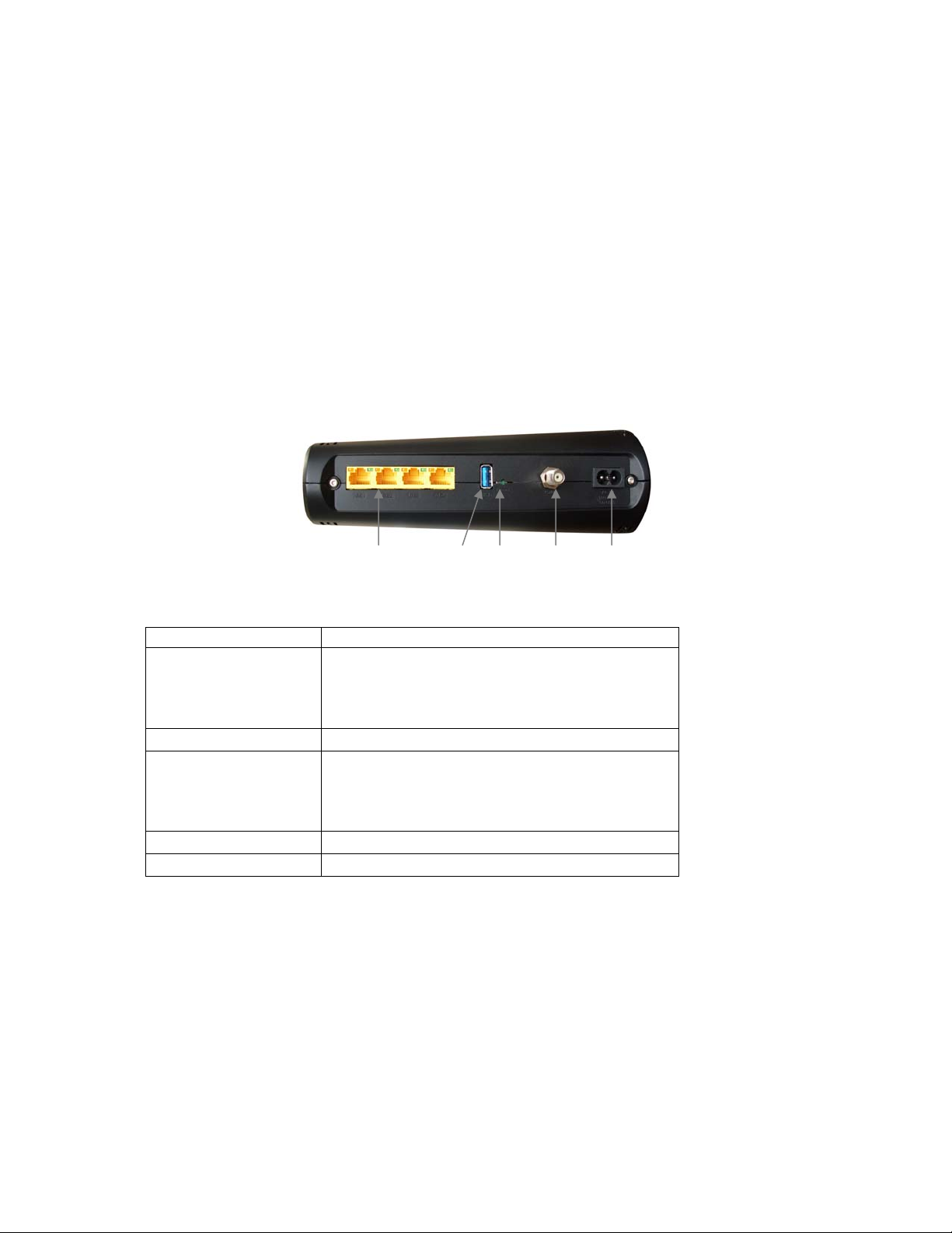
Hardware Connection
GE/ LAN 1-4 USB RESET Cable AC IN
Port Description
GE 1-4
(Gigabit Ethernet 1-4
also known as LAN
1-4)
Four 10/100/1000 auto-sensing RJ-45 ports.
Connect devices on your LAN (Local Area
Network) such as a computer, hub or switch to
these ports.
USB The USB port is for manufacturer’s use only.
Use this button in the unlikely event that you want
RESET
to restore the default factory settings. This button
is recessed to prevent accidental resets of your
cable modem/router.
Cable Connect your coaxial cable line to this port.
AC IN Connect the supplied power cord to this port.
Connecting the Cable Modem/Router Wirelessly to Some Device
Your cable modem/router has wireless-N for WiFi® compatible connection to your computer
and/or other devices. The cable modem/router comes set up by default with WPA/WPA2 security,
and this can be changed if you like.
10
Page 11

For those computer(s) and/or device(s) that support WPS, see
Using WPS to set up your wireless
network. For those computer(s) and/or device(s) that do support WPA/WPA2 but that don’t
support WPS, enter the default SSID and Pre-Shared Key below in the wireless network portion of
the device’s configuration menus. (If you want setup tips for computers and other wireless-enabled
devices, go to
Appendix A: Tips for setting up computers and other devices on a wireless
network.)
Note: Typically, tablets like the iPad and e-readers don’t support WPS but do support WPA/WPA2.
Default Wireless Security Settings
The default SSID is: ZOOM
The default Pre-Shared Key is: zoom#### where #### represents the last
4 characters of the Cable MAC address of the unit, which can be found on the label
on the bottom of the cable modem/router.
Note: If you want to change the default SSID and Pre-Shared Key, please refer to page 15 for
instructions.
In the unlikely event that one or more of your devices only supports WEP security, please refer to page 18
for instructions on how to configure WEP security.
Using WPS to set up your wireless network
If all the WiFi compatible wireless devices on your network support WPS:
1 Press the WPS LED pushbutton on the front panel of the router for 5 seconds. The WPS LED
should blink green.
2 Within 2 minutes (before the WPS LED light turns off), press the WPS button on the device that
you’re linking wirelessly to the modem/router. The button may be a physical pushbutton on the
device or a button on a page of the device’s wireless network configuration menus.
Note: Windows 7 SP1 (Service Pack 1) or the latest updates, or Windows Vista SP2
(Service Pack 2) users can use WPS for easy configuration.
a Open Connect to a Network by right-clicking the network icon in the
notification area of the Windows taskbar.
b A list of available networks is displayed.
c Click ZOOM (or the SSID you changed the default to), and then click Connect.
d You may see a screen with a text box for the Security key. If WPS configuration is
supported, you may see a message such as You can also connect by pushing the button on the
router.
11
Page 12
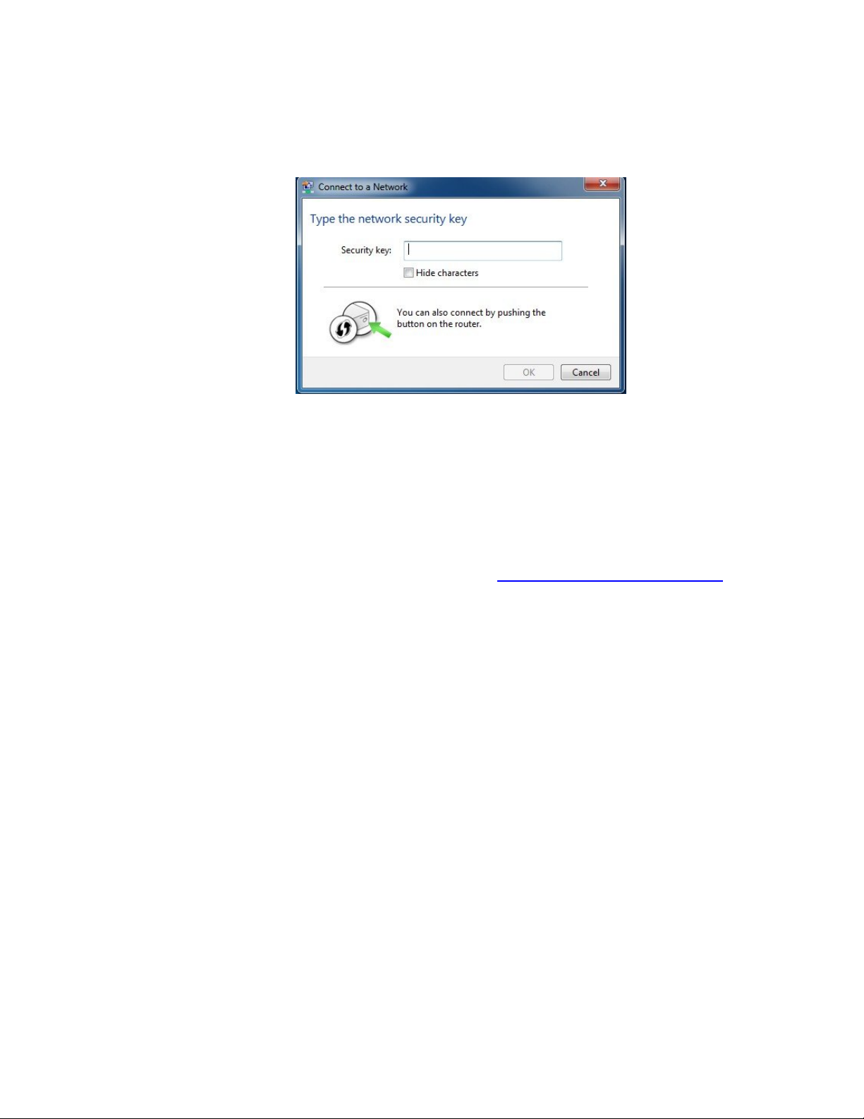
Press the Wi‑Fi Protected Setup (WPS) button on the router for 5 seconds. (You do not
need to type a security key or passphrase in the Security key text box on your Windows
machine). The cable modem/router will automatically set up the computer to connect to
the network and apply the network's security settings. Then click OK on the Connect to
a Network dialog box.
3 Congratulations! You should now have a secure connection between your cable modem/router
and a device. Now is a good time to check that your device’s Internet connection is working.
Open your browser and go to a familiar Web site. If you are able to connect, continue with the
next step below.
If you are not able to connect to the Internet, please see
AppendixB: Troubleshooting Tips.
4 If you have other devices whose WPS security you need to set, repeat steps 1 through 3 for each
device. When they are all set, go to step 5.
5 Your basic setup for local wireless devices is complete.
Note: If you want to change the default SSID and Pre-Shared Key, please refer to page 15 for
instructions.
Read This Only if You Are Connecting Additional Computers and/or Other Devices to the
Cable Modem/Router’s Ethernet/LAN ports
You can plug up to four computers, game consoles, or other Ethernet-capable devices into the cable
modem/router’s LAN ports. For information about your specific device, please refer to the
documentation that came with that device. Follow the instructions below for each computer or other
device.
1 If you connected the cable modem/router to a computer using a wired connection when setting
up the cable modem/router, unplug the computer now if you don’t want it to stay connected to
the cable modem/router.
2 To connect a computer or other Ethernet-capable device, plug one end of an Ethernet cable into
an available Ethernet (GE 1, 2, 3, or 4) port on the cable modem/router and plug the other end
of the Ethernet cable into the Ethernet port of the additional device you want to connect to the
12
Page 13

cable modem/router. (If you are connecting a hub or a switch, this is typically called an Uplink or
Expansion port.) If you are connecting a computer or game station, go to step 5 of this
section.
3 If you are connecting a network device such as a switching hub, use the instructions that came
with that device. Then reboot any computer that is part of your network. For example, if you
connected a switching hub, reboot any computer that will be connected to that switching hub.
4 If you are connecting a HomePlug adapter pair with one adapter plugged into the cable
modem/router and an AC outlet, and the other adapter plugged into a computer or game station
and an AC outlet, make those connections and then go to step 5.
5 Verify that your Internet connection is working. Open a Web browser on each computer that’s
using your network and try to connect to a familiar Web address.
Note: If at any time you need to make changes to the cable modem/router’s configuration, open
a web browser from any PC on your cable modem/router’s network and type http://192.168.0.1
to open the Zoom Configuration Manager. Alternately, you can connect a computer directly to
the cable modem/router, open its browser, and then type http://192.168.0.1.
6 Congratulations! You have connected an additional device to the Internet. You can connect up
to 4 Ethernet-capable devices to the cable modem/router, following the instructions above for
each device and starting at step 2 of this section.
If you want to set up a wireless network, please refer to
Wireless Network. (Most newer Windows 7, Vista, and XP computers with built-in
wireless networking capabilities do not require the installation of a wireless component. If
this is the case, you should set up that computer’s wireless connection if it isn’t already
configured using the Windows 7, Vista, or XP connect utility. See
instructions.)
If you want to configure advanced options, continue with the section Logging in to the
Zoom Configuration Manager. Then refer to the
this User Manual for instructions for the feature(s) you want to configure.
Appendix A: Setting Up Your
Appendix A for
Table of Contents at the beginning of
Logging in to the Zoom Configuration Manager
Step 1: Connecting the Router to a Computer
1 Connect the router to a computer following the instructions under How to connect to a
computer if you don’t have or choose not to use a cable modem starter kit. Then continue
to Step 2 below.
Step 2: Establishing Communication
1 Open your Web browser, enter http://192.168.0.1 in the address bar, and press the Enter key to
open the Cable Modem/Router configuration software.
13
Page 14

2 In the Enter Network Password dialog box, type the following User Name and Password in
lower case, then click OK.
User Name: admin
Password: admin
3 The Status page should appear. If the Status page doesn’t appear, please see
Troubleshooting Tips.
Appendix B:
From the Zoom Configuration Manager, you can configure advanced features and make changes to
the default wireless security options including the SSID and Pre-Shared Key.
If you want to change the default SSID or Pre-Shared Key, go to
Key and SSID from the default settings.
If you need instructions for setting up a wireless network, please refer to
Setting Up Your Wireless Network. (Most newer Windows 7, Vista, and XP
computers with built-in wireless networking capabilities do not require the installation
of a wireless component. If this is the case, you should set up that computer’s wireless
connection if it isn’t already configured using the Windows 7, Vista, or XP connect utility.
Appendix A for instructions.)
See
Otherwise, refer to the Table of Contents to select a specific topic for advanced options.
Changing the Pre-Shared
Appendix A:
14
Page 15

2
Setting Wireless Security
Your cable modem/router comes from the factory with, security turned on by def ault. If you want
to use another security mode instead of the default security mode of WPA-PSK/WPA2-PSK , or
if you want to change the Pre-Shared Key, this chapter explains how.
There are two basic wireless security modes, WPA and WEP. There are two versions of WPA: WPA
and WPA2. When configured as part of a typical home or small office network, WPA and WPA2
require a Pre-Shared Key, or PSK. These modes are typically called WPA-PSK and WPA2-PSK,
respectively, though sometimes they’re just called WPA and WPA2. You can enable either WPA-PSK
or WPA2-PSK alone, or you can enable both WPA-PSK and WPA2-PSK together. By default, your
cable modem/router has both WPA-PSK and WPA2-PSK enabled. You will only need to change the
security mode if you know that you have a device you are connecting to your wireless network that
only supports WEP. (Go to
an unsecured network, this is discussed late in this chapter in Disabling Security.
Note: If you have a Radius Server (very unlikely for a home network), select the WPA/WPA2
options without PSK. All instances of WPA and/or WPA2 that follow refer to WPA-PSK and/or
WPA2-PSK unless noted otherwise.
You can check to see if all other clients that you plan to put on the network support WPA or WPA2.
You can do this by checking the manual that came with each device or by checking the configuration
software for the installed device. Look under Security or Encryption or Setup or Advanced
Features.
devices.
If all of the devices you want to connect to your wireless network support WPA or WPA2 you may
want to change the Pre-Shared Key and/or change the Network Name (SSID. In that case, go below
Changing the Pre-Shared Key and SSID from the default settings. For instructions on
to
configuring WPA/WPA2 Security with your devices, go to
If any of the devices you want to connect to your wireless network do not support WPA or WPA2, go
to
Setting Up Security Using WEP.
Appendix A discusses how to check the configuration software for various wireless
Setting Up Security Using WEP.) In the unlikely event that you want
WPA/WPA2 Security.
15
Page 16

If you need to set up an unsecured network, see
Changing the Pre-Shared Key and SSID from the default settings
In the default security setting, both WPA-PSK and WPA2-PSK are enabled. The default SSID is
ZOOM and Pre-Shared Key is
the Cable MAC address of the unit, which can be found on the label on the bottom of the cable
modem/router. If you want to change the SSID and/or the Pre-Shared Key, go to WPA/WPA2
Security.
zoom#### where #### represents the last 4 characters of
Disabling Security.
WPA/WPA2 Security
WPA and WPA2 use a passphrase or PSK that you choose and enter on the Cable Modem/Router
and other wireless devices on the network (clients) to set up security. To use WPA/WPA2, all of the
wireless devices on your network must support either encryption method. If you know that all your
devices support the more secure WPA2 you can enable WPA2 only instead of both WPA and WPA2.
1 Open the Zoom Configuration Manager by typing the following in your Web browser's address
http://192.168.0.1
bar:
2 In the Enter Network Password dialog box, type the following User Name and Password in
lower case, then click OK..
User Name: admin
Password: admin
(The User Name and Password entered here are not the same as the User Name and Password
that your Internet service provider may have given you.)
3 Click Wireless on the top menu.
4 Then click Primary Network on the left-side menu and in the text box labeled Network Name
(SSID), type an SSID of your choice. The SSID needs to be at least one character long, and it’s
probably best to pick a name that you’ll recognize as yours.
5 Start by setting all the following drop-down menus to Disable: WPA, WPA-PSK, WPA2, and
WPA2-PSK.
6 Then select Enable for the mode(s) you choose for setting wireless security.
Note: To use WPA2 /WPA, all of the wireless devices on your network must support either
encryption method. In this case, enable:
o WPA-PSK and WPA2-PSK (if you want to use a Pre-Shared Key)
or
o WPA and WPA2 (use this only if your network uses a Radius Server. This is very
uncommon for a home network)
16
Page 17

If you know that all your devices support the more secure WPA2 you can enable WPA2 only (or
WPA2-PSK if you want to use a Pre-Shared Key) instead of WPA and WPA2.
7 In the WPA Pre-Shared Key text box (only if you selected an option requiring a Pre-Shared Key),
enter a passphrase of your choice (a minimum of 8 characters). Write down this passphrase and
put it where you can find it – on the bottom of the Cable Modem/Router case, for instance.
8 Click Apply.
9 Now you need to set up each of your wireless devices with the SSID and passphrase.
a First, make sure that the device's wireless capability is switched on. (Many
notebooks have a switch for wireless, for instance.)
b Next go to the device’s area for configuring a wireless network connection. (If you
need them, tips for finding this area are in
Appendix A.)
• For a Windows computer, click the Wireless Networking icon at the
lower right corner of the screen.
• For another device such as an iPhone or iPad, you may have to click on
something like Settings and then WiFi. Skip (c) and continue with (d)
below.
c Select the Site Survey or Scan option to see a list of the access points in your area.
That list should include the SSID ZOOM or the SSID you created.
d Select ZOOM (or the SSID you created).
Note: If any of your devices support WPS, you can configure WPS for those
devices. Press the WPS LED pushbutton on the front panel of the router for 5
seconds. The WPS LED should blink green. Within 2 minutes (before the WPS
LED light turns off), press the WPS button on the device that you’re linking
wirelessly to the modem/router. The button may be a physical pushbutton on the
device or a button on a page of the device’s wireless network configuration menus.
Skip (e) and (f).
Windows 7 (SP1) Service Pack 1 or the latest updates, or Windows Vista SP2
users, you can use WPS for easy configuration. Click Connect. Then press the
17
Page 18
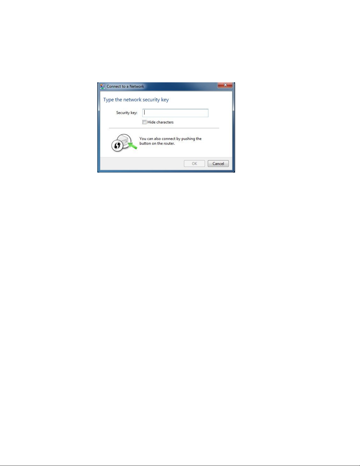
Wi‑Fi Protected Setup (WPS) button on the router for 5 seconds.
(You do not need to type a security key or passphrase in the Security Key text box
on your Windows machine). The cable modem/router will automatically set up the
computer to connect to the network and apply the network's security settings.
Then click OK on the Connect to a Network dialog box. Skip (e) and (f).
e Enter the Pre-Shared Key that you just wrote down in Step 7.
f Save your settings.
That’s it! Your security setup is now complete!
Setting Up Security Using WEP
If any of your network devices DO NOT support WPA or WPA2, you can use WEP to configure
network security. WEP can be configured two ways: 64-bit and 128-bit. 128-bit WEP provides more
security than 64-bit.
1 Open the Zoom Configuration Manager by typing the following in your Web browser's address
http://192.168.0.1
bar:
2 In the Enter Network Password dialog box, type the following User Name and Password in
lower case, then click OK..
User Name: admin
Password: admin
(The User Name and Password entered here are not the same as the User Name and Password
that your Internet service provider may have given you.)
3 Click Wireless on the top menu.
4 Then click Primary Network on the left-side menu.
18
Page 19

5 From the WEP Encryption drop-down menu, select WEP-64 bit (or WEP-128 bit for more
security).
6 For Network Key 1, you can either enter your own WEP Key or you can have WEP Keys
generated.
If you are entering a network key of your choice, enter 13 ASCII characters or 26 hexadecimal
digits for 128-bit encryption keys. Enter 5 ASCII characters or 10 hexadecimal digits for 64-bit
encryption keys.
Otherwise, type something into the text box and click on Generate WEP Keys and WEP Keys
will automatically be generated for you.
Caution! Do not click Apply until you have entered WEP Keys.
7 Click Apply.
Every wireless network client needs to be set individually. Open the wireless configuration software
that came with the device, which should be running on the computer where the device is installed.
(Tips for finding the wireless configuration section of your device can be found in
Find the configuration menu for security, choose WEP, and enter the Network Key, exactly as you
entered it or exactly as it was generated for you on the Cable Modem/Router Wireless page.
Your security setup configuration is now complete!
Appendix A.)
Disabling Security
If for some reason you need to set up an unsecured network, you will need to disable the default
security that is currently set up for your cable modem/router. Follow the instructions below.
1 Open the Zoom Configuration Manager by typing the following in your Web browser's address
http://192.168.0.1
bar:
2 In the Enter Network Password dialog box, type the following User Name and Password in
lower case, then click OK..
User Name: admin
Password: admin
(The User Name and Password entered here are not the same as the User Name and Password
that your Internet service provider may have given you.)
3 Click Wireless on the top menu.
4 Then click Primary Network on the left-side menu and in the text box labeled Network Name
(SSID), type an SSID of your choice. The SSID needs to be at least one character long, and it’s
probably best to pick a name that you’ll recognize as yours.
5 Set all the following drop-down menus to Disable: WPA, WPA-PSK, WPA2, and WPA2-PSK.
6 Click Apply.
19
Page 20

7 Now you need to set up each of your wireless devices with the SSID.
a First, make sure that the device's wireless capability is switched on. (Many
notebooks have a switch for wireless, for instance.)
b Next go to the device’s area for configuring a wireless network connection. (If you
need them, tips for finding this area are in
Appendix A.)
• For a Windows computer, click the Wireless Networking icon at the
lower right corner of the screen.
• For another device such as an iPhone or iPad, you may have to click on
something like Settings and then WiFi. Skip (c) and continue with (d)
below.
c Select the Site Survey or Scan option to see a list of the access points in your area.
That list should include the SSID ZOOM or the SSID you created.
d Select ZOOM (or the SSID you created).
That’s it! You have now disabled security.
If you are like most users, you don’t need to read further in this manual. You do want to read further
if you are a network administrator or if you are using the Cable Modem/Router with Wireless-N for
gaming or something else that requires special settings.
You can skip to specific sections of this User Manual based on your intended use of the Cable
Modem/Router with Wireless-N. Each of the menu options in your Configuration Manager is
covered as a separate chapter in the remaining portion of the User Manual. Refer to the chart on the
next page to go to a specific menu option.
20
Page 21

Chapter
3
Menu
Options
Status
Go to this section if you
want to…
monitor or troubleshoot
problems with the cable
See
Page
25
modem/router
Basic
4
5
Advanced
6
Firewall
make some modifications
for more advanced uses
make use of advanced router
features supported by the
cable modem/router
configure the firewall
application to protect the
private LAN from attacks
33
40
54
from the WAN interface
7
Parental
Control
configure access policies or
rules to specific network
devices based on the time of
62
day and Internet contents
8
Wireless
9
VPN
configure and use the
wireless features supported
by the cable modem/router
enable the VPN protocol
and configure IPSec tunnels,
L2TP and PPTP server
70
88
options
21
Page 22
Accessing the Cable Modem/Router’s Configuration Manager
From your Web browser, you will log in to the interface to define system parameters, change
password settings, view status windows to monitor network conditions, and control the cable
modem/router and its ports.
To access the cable modem/router’s Configuration Manager, use the following procedure:
1 Launch a Web browser.
Note: Your computer does not have to be online to configure your cable modem/router.
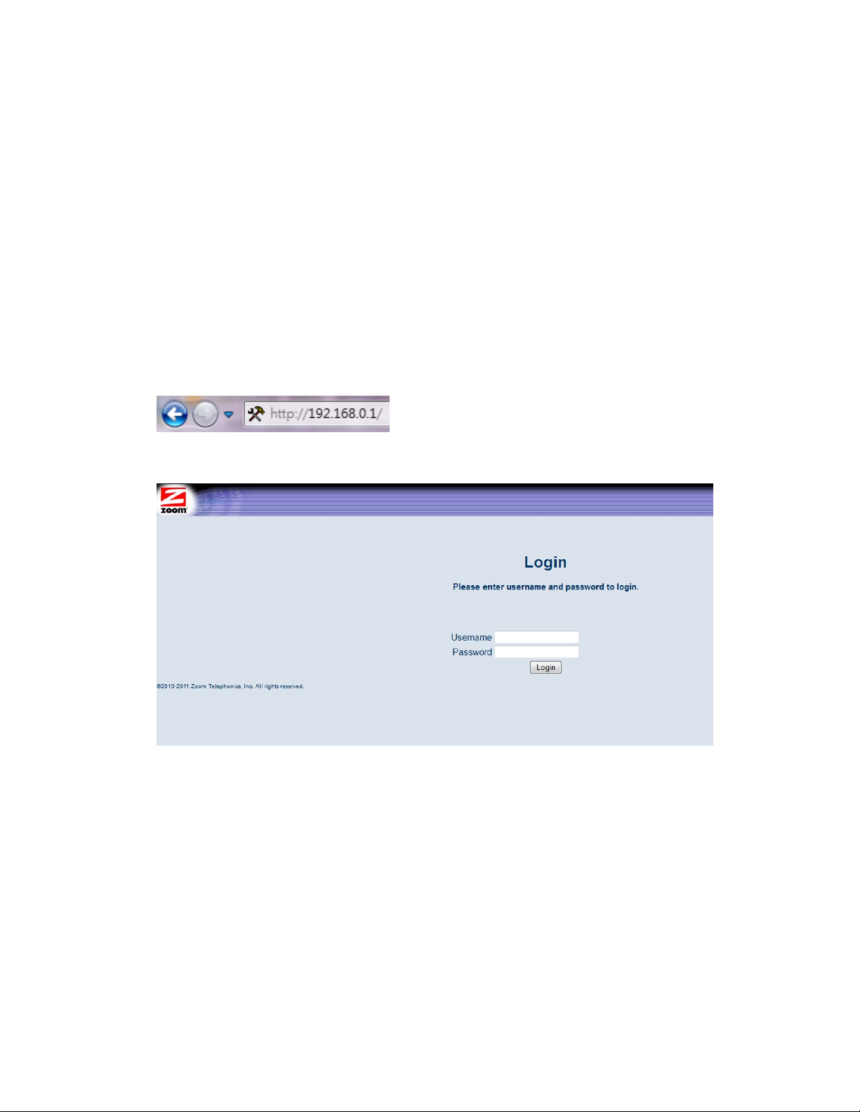
2 In the browser address bar, type http://192.168.0.1 and press the Enter key.
For example:
The Login screen appears (see
Figure 1. Login Screen
3 In the Login screen, enter:
Figure 1)
default username: admin
default password: admin
Both the username and password are case sensitive. After you log in to the Zoom Configuration
Manager interface, you can change the default password on the Status - Security page.
22
Page 23
Menu Bar
Submenu
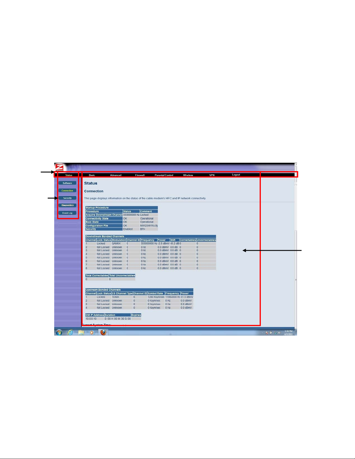
4 Click the Login button to access the cable modem/router. The Status page appears, showing
connection status information about your cable modem/router.
Understanding the Configuration Manager Interface Screens
The top of the management interface contains a menu bar you use to select menus for configuring the
cable modem/router. When you click a menu item, information and any configuration settings
associated with the menu appear in the main area of the interface (see
Figure 2). If the displayed
information exceeds what can be shown in the main area, scroll bars appear to the right of the main
area so you can scroll up and down through the information.
Figure 2. Main Areas on the Configuration Manager Interface
Every menu has submenus associated with it. If you click a menu item, the submenus appear on the
left frame of the Configuration Manager. For example, if you click the Status menu item, the
submenu Software, Connection, Security and Diagnostics appear on the left column (see
3
).
Figure
Main Area
23
Page 24
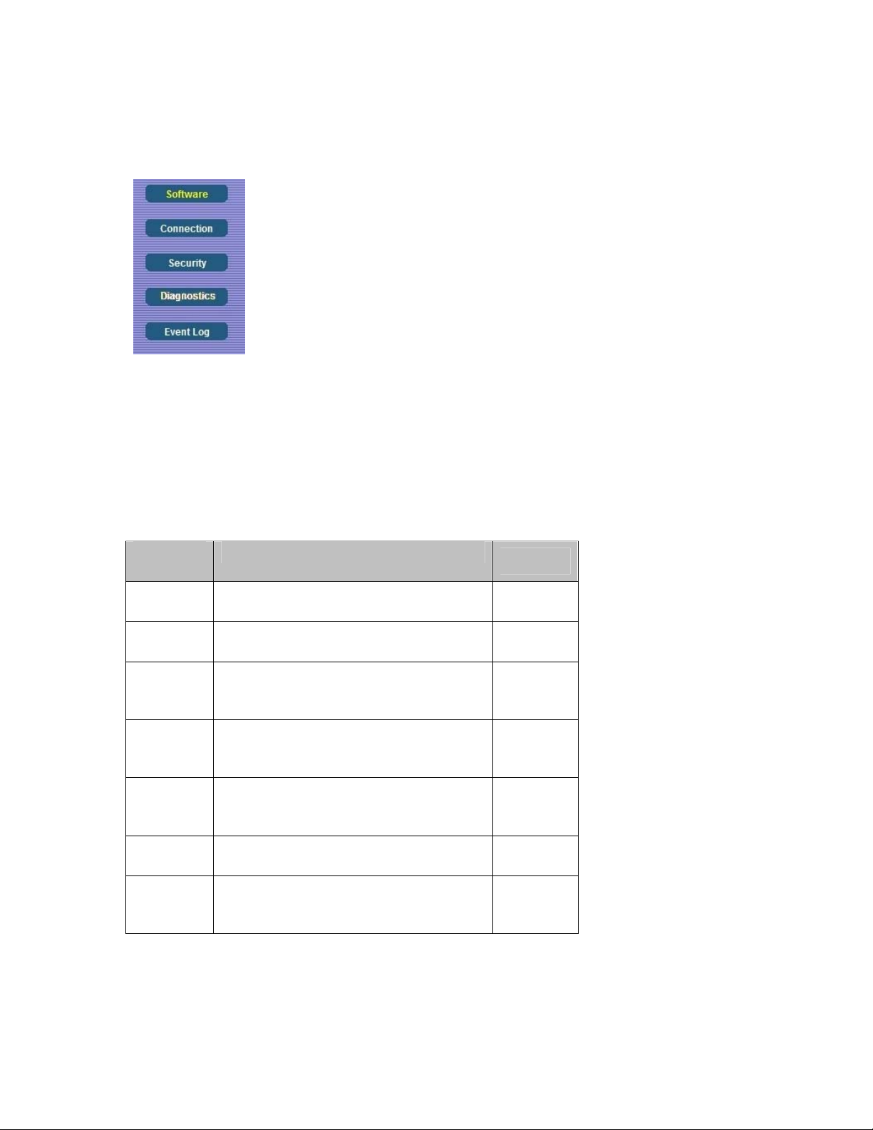
Figure 3. Example of Status Submenu
The right-most item on the menu bar is the logout option. Click it to log out from the Configuration
Manager interface.
Configuration Manager Interface Menus
Table 1 describes the menus in the Configuration Manager interface.
Table 1. Configuration Manager Interface Menus
Menu
Options
Status
Basic
Go to this section if you want to…
monitor or troubleshoot problems with the
cable modem/router
make some modifications for more
advanced uses
See Page
25
33
make use of advanced modem/router
Advanced
features supported by the cable
40
modem/router
configure the firewall application to protect
Firewall
the private LAN from attacks from the
54
WAN interface
Parental
Control
Wireless
configure access policies or rules to specific
network devices based on the time of day
and Internet contents
configure and use the wireless features
supported by the cable modem/router
62
70
enable the VPN protocol and configure
VPN
IPSec tunnels, L2TP and PPTP server
88
options
24
Page 25

3
Status Menu Options
The Status Menu lets you:
¾ View the status and connection information of the cable modem/router
¾ Change the administrator password
¾ Use diagnostic tools for troubleshooting
Software
The Software page is a read-only screen that shows the cable modem/router’s current system
software version. This page appears when you first log in to the Configuration Manager interface.
You can also display it by clicking Status in the menu bar and then click the Software submenu.
Figure 4 shows an example of the menu and Table 2 describes the items you can select.
25
Page 26
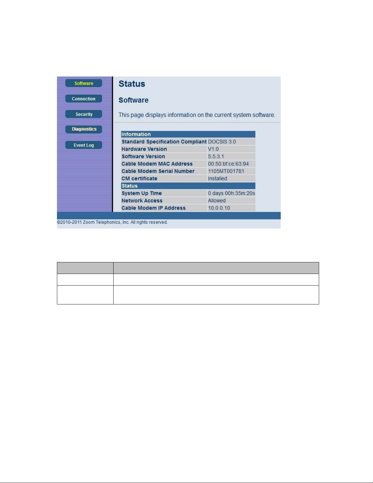
Figure 4. Software Menu
Table 2. Software Menu Option
Option Description
Information Shows the information on the current system software.
Status
Shows the system up time, network accessibility, and IP address of the Cable
modem/router.
Connection
The Connection page is a read-only screen that shows the status of steps in your cable modem/router
registration process. It also shows your cable modem/router’s upstream and downstream channel
status.
To access the Connection page, click Status in the menu bar and then click the Connection
submenu.
Figure 5 shows an example of the menu.
26
Page 27
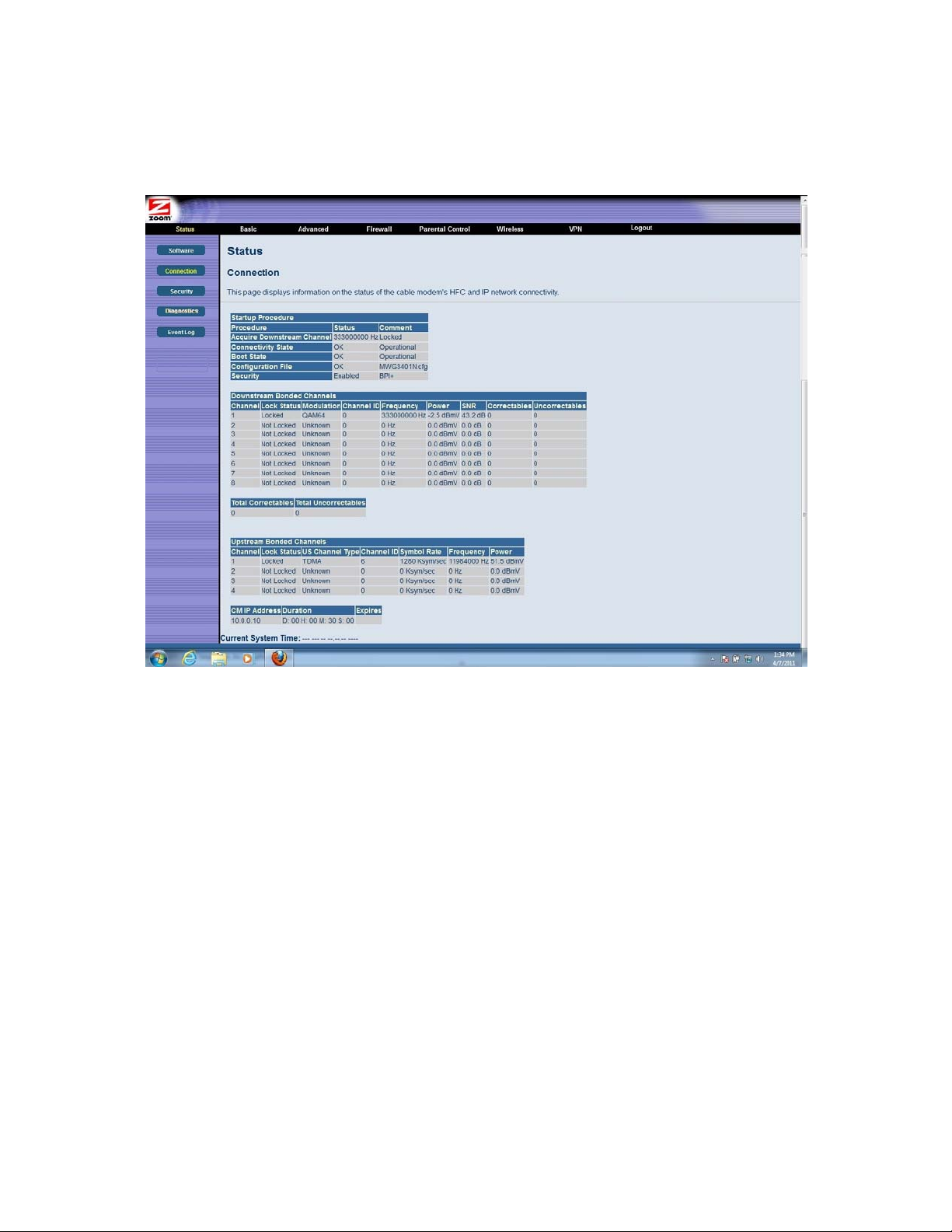
Figure 5. Example of Connection Page
Security
The Security page allows you to configure access privileges and restore the cable modem/router to its
factory defaults.
To access the Security page, click Status in the menu bar and then click the Security submenu.
6
shows an example of the menu and Table 3 describes the items you can select.
27
Figure
Page 28
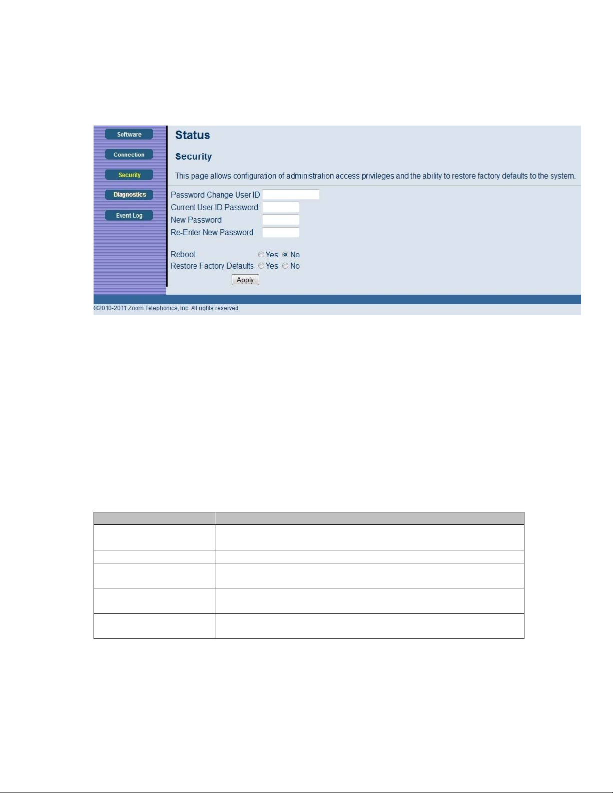
Figure 6. Example of Security Page
To restore the cable modem/router to factory defaults:
1 In the Security submenu, select the Yes button next to Restore Factory Defaults.
2 Click Apply.
3 Click OK to reboot the cable modem/router. The reboot is complete when the POWER LED
stops blinking.
4 If the Login screen doesn’t reappear, click the Refresh link to log back in to the Configuration
Manager.
Table 3. Security Menu Option
Option Description
Password Change User
ID
Enter the new ID for the administrator.
New Password Enter the new security password.
Re-Enter New
password
Current User ID
Password
Restore Factory
Defaults
Re-enter (confirm) the new security password.
Enter the current ID of the administrator.
Allows you to reset to factory default settings.
Note: You DO NOT have to restore factory defaults to change the password.
28
Page 29

Diagnostics
Note: Some versions may not support this feature.
The Diagnostics page allows you to troubleshoot connectivity problems. Two utilities are provided
for troubleshooting network connectivity: Ping and Traceroute.
Ping allows you to check connectivity between the cable modem/router and devices on the LAN
while Traceroute allows you to map the network path from the cable modem/router to a public host.
Selecting Traceroute from the drop-down Utility list will present alternate controls for the Traceroute
utility.
To access the Diagnostics page, click Status in the menu bar and then click the Diagnostics
submenu.
Figure 7 and Figure 8 show the examples of the menu and
29
Page 30
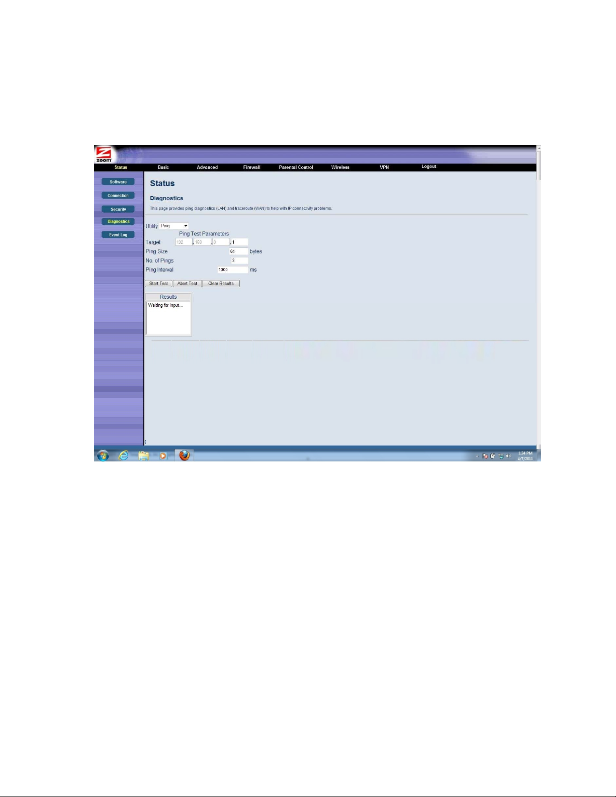
Table 4 describes the items you can select.
Figure 7. Example of Diagnostics - Ping Page
30
Page 31

Figure 8. Example of Diagnostics - Traceroute Page
To run either utility:
1 Select the utility from the Utility drop-down list.
2 Make any changes to the default parameters.
3 Select Start Test to begin. The window will automatically be refreshed as the results are displayed
in the Results table.
31
Page 32

Table 4. Diagnostics Menu Option
Option Description
Utility Select the utility for troubleshooting.
Parameters Enter the required parameters to perform diagnostics.
Start Test
Click this button to begin diagnostic after making any changes to the default
parameters.
Abort Test Click this button to abort Ping diagnostics.
Clear Results Click this button to clear the results table.
Event Log
The Event Log page shows the SNMP event log.
To access the Event Log page, click Status in the menu bar and then click the Event Log submenu.
Figure 9 shows an example of the menu and Table 5 describes the items you can select.
Figure 9. Event Log Page
Table 5. Event Log Menu Option
Option Description
Time Shows the local time of a log event.
Priority Shows the priority level of an event.
Description Shows detailed information of an SNMP event.
32
Page 33

4
Basic Menu Options
The Basic Menu lets you:
¾ Configure the basic settings of your cable modem/router
¾ Configure DHCP server for the LAN
¾ Configure DDNS service
¾ Backup and restore of configuration settings
Setup
The Setup page allows you to configure the basic features of the cable modem/router related to your
ISP’s connection.
To access the Setup page, click Basic in the menu bar and then click the Setup submenu.
shows an example of the menu and Table 6 describes the items you can select.
Figure 10
33
Page 34

Figure 10. Example of Setup Page
Table 6. Setup Menu Option
Option Description
LAN IP Address
WAN
Connection Type
Set the base LAN IP for your private network. By default this is 192.168.0.1
There is normally no need to change this.
Select how your cable modem/router obtains an IP address. The options are
via DHCP or manual configuration of a static IP address. Unless you have
arranged for a static IP address from your service provider, you should leave
this setting at its default, DHCP.
34
Page 35

DHCP
The DHCP page allows you to configure your cable modem/router’s DHCP server.
To access the DHCP page:
1 Click Basic in the menu bar.
2 Then click the DHCP submenu.
Figure 11 shows an example of the menu and Table 7 describes the items you can select.
Figure 11. Example of DHCP Page
35
Page 36

In the unusual event that you have a separate DHCP server on your LAN, you can disable the cable
modem/router’s DHCP server by selecting the No radio button. If you do this, make sure the IP
address assigned to the cable modem/router is on the same subnet as that of the external DHCP
server, or you won’t be able to access the cable modem/router from the LAN. The base LAN IP
address of the cable modem/router can be set from the Basic Setup page.
Note that the cable modem/router will only operate on a class C subnet, with subnet mask
255.255.255.0
You may also want to disable the DHCP server if you have assigned static IP addresses to all devices
on your network.
Table 7. DHCP Menu Options
Option Description
DHCP Server
Starting Local
Address
Number of
CPEs
Lease Time
Select Yes to use internal DHCP server of the cable modem/router, or select
No to disable it.
Configure the starting IP address for IP leases available to devices on the
LAN.
Configure the number of PCs supported on the LAN.
Configure the time a lease will last before it must be renewed. Default is 3600
seconds , or 1 hour.
DDNS
The DDNS page allows you to make use of a DDNS server. Dynamic DNS (DDNS) allows a
dynamic IP address to be aliased to a static, pre-defined host name so that the host can be easily
contacted by other hosts on the internet even if its IP address changes. This means you can host a
server on your LAN that can be accessed from anywhere on the Internet.
Caution: Some service providers may consider connection of such a server to be a breach of your
service agreement.
The cable modem/router supports a dynamic DNS client compatible with the Dynamic DNS service
http://www.dyndns.com/). You must sign up with this service if you want to use it.
(
To access the DDNS page:
1 Click Basic in the menu bar.
2 Then click the DDNS submenu.
36
Page 37

Figure 12 shows an example of the menu and Table 8 describes the items you can select.
Figure 12. Example of DDNS Page
To activate the DDNS client:
1 Go to the DynDNS website and create an account for the Dynamic DNS service.
2 You will create a username and password, and be asked to choose a host name for your server,
and the dynamic DNS domain to which your host will be assigned.
3 You will also be asked for your host’s current IP address. This is the WAN IP address that has
been assigned to your cable modem/router during provisioning. (See WAN IP Address on the
Basic / Setup web page.)
4 Enter your account information on the Basic / DDNS web page, enable the service by selecting
www.DynDNS.org from the DDNS Service drop-down list, and click Apply.
5 The DDNS client will notify the DDNS service whenever the WAN IP address changes so that
your chosen host name will be resolved properly by inquiring hosts. The current status of the
service is shown at the bottom of the DDNS web page.
37
Page 38

Table 8. DDNS Menu Option
Option Description
DDNS Service
Select the type of service that you are registered for from your DDNS service
provider.
User Name Enter your DDNS account username subscribed to the service provider.
Password Enter the password of the account.
Host Name Enter the host name of your service host.
IP Address Shows the current WAN side public IP address.
Status Shows the status of DDNS service.
Backup
Note: Some versions may not support this feature.
The Backup page allows you to save the current cable modem/router configuration settings to a local
PC. You can then later restore these settings if you need restore a particular configuration, or to
recover from changes you may have made that have had an undesirable effect.
To backup the current configuration:
Click Backup and follow the prompts.
To restore a previous configuration:
Click Browse and use the navigation window to locate the file. (Usually cable modem/router
Settings.bin, unless you rename it before saving.) Once the file has been located, click Restore to
restore the settings.
Note: Once the settings are restored, the device will reboot.
To access the Backup page:
1 Click Basic in the menu bar.
2 Then click the Backup submenu.
Figure 13 shows an example of the menu.
38
Page 39

Figure 13. Example of Backup Page
39
Page 40

5
Advanced Menu Options
The Advanced Menu lets you:
¾ Enable advanced features of the cable modem/router
¾ Configure LAN IP address, MAC address, and port number filtering
¾ Configure WAN to LAN port forwarding and triggers
¾ Configure DMZ hosting
¾ Configure RIP parameters
Options
The Options page allows you to configure the cable modem/router to operate in different modes that
adjust how the device routes IP traffic.
To access the Options page:
1 Log in to the Configuration Manager (see page 13 for instructions).
2 Click Advanced in the menu bar.
3 Then click the Options submenu.
Figure 14 shows an example of the menu and Table 9 describes the items you can select.
40
Page 41

Figure 14. Example of Options Page
To enable a feature:
1 Click the appropriate check box (a check mark will appear).
2 When you are done with your selections, click on the Apply button.
41
Page 42

Table 9. Options Menu Option
Option Description
Prevents the cable modem/router or the PCs behind it from being visible to
the WAN (i.e. from the Internet). For instance, pings to the cable
WAN Blocking
modem/router’s WAN IP address or to the devices behind it are not
returned. This makes it more difficult for hackers to attack your PCs and
other devices on your network.
IPSec/PPTP
PassThrough
Remote
Configuration
Management
Multicast Enable
UPnP Enable
RgPassThrough
Enable to support VPN devices or software on your network.
Allows the cable modem/router to be remotely administered at port 8080.
When enabled, navigate to http://CMIPAddress:8080/ to administer the
cable modem/router remotely). You can find your CM: WAN IP address on
Basic Setup page.
the
Allows multicast specific traffic (denoted by a multicast specific address) to
be passed to and from the PCs on the private network behind the cable
modem/router.
Select Enable to enable the UPnP agent in the cable modem/router. If you
are running an application that requires UPnP, check this box.
Allows PCs behind the cable modem/router to bypass the cable
modem/router DHCP server and NAT functions. PCs or other IP devices
can be added to the passthrough table by entering the MAC addresses of the
devices into the passthrough table.
42
Page 43

IP Filtering
The IP Filtering page allows you to configure IP address filters in order to block Internet traffic to
specific network device on your LAN. By entering starting and ending IP address ranges, you can
configure which local PCs are denied access to the WAN.
To access the IP Filtering page:
1 Click Advanced in the menu bar.
2 Then click the IP Filtering submenu.
Figure 15 shows an example of the menu and Table 10 describes the items you can select.
Figure 15. Example of IP Filtering Page
43
Page 44

To activate the IP address filter:
1 Enter the last byte (the numbers after the last period) of the IP address in Start Address and
End Address.
2 Check the Enable box to the right of the entry to store settings.
3 Click the Apply button to activate the filter rules.
Table 10. IP Filtering Menu Option
Option Description
Start/End
Address
Enter the last byte of the IP address. The upper bytes of the IP address are set
automatically from the cable modem/router IP address.
To activate the IP address filter, you must also check the Enable box and click
Enable
Apply. You can disable this filter while retaining the addresses you entered for
later use.
MAC Filtering
The MAC Filtering page allows you to configure MAC address filters in order to block Internet traffic
to specific network devices on your LAN.
To access the MAC Filtering page:
1 Click Advanced in the menu bar.
2 Then click the MAC Filtering submenu.
Figure 16 shows an example of the menu and Table 11 describes the items you can select.
44
Page 45

Figure 16. Example of MAC Filtering Page
Table 11. MAC Filtering Menu Option
Option Description
PCs and other devices can be added to the MAC filter table by entering their
MAC Address
MAC addresses into the Add MAC Address box, and clicking the Add MAC
Address button. Internet traffic to and from each listed Address will be
blocked.
45
Page 46

Port Filtering
The Port Filtering page allows you to configure port filters in order to block Internet traffic to specific
ports on all devices on your LAN.
Similarly, you can prevent PCs from sending outgoing TCP/UDP traffic to the Internet from specific
IP port numbers. This can be configured using the Port Filtering page.
To access the Port Filtering page:
1 Click Advanced in the menu bar.
2 Then click the Port Filtering submenu.
Figure 17 shows an example of the menu and Table 12 describes the items you can select.
Figure 17. Example of Port Filtering Page
46
Page 47

For example, if you would like to block all PCs on the private LAN from accessing HTTP sites (or
“web surfing”):
1 Set the Start Port to 80, the End Port to 80.
2 Set the protocol to TCP.
3 Check the Enable box to the right of the entry to store settings.
4 Click Apply button to activate the filter rules.
Table 12. Port Filtering Menu Option
Option Description
Start/End Port Enters the start and end port of the port filter range
Protocol Filter either both TCP and UDP traffic or just UDP or just TCP.
Forwarding
The Forwarding page allows you to run a publicly accessible server from your LAN by specifying the
mapping of TCP/UDP ports to a local PC. It allows incoming requests to specific port numbers to
reach a web server, FTP server, mail server, etc.
To access the Forwarding page,
1 Click Advanced in the menu bar.
2 Then click the Forwarding submenu.
Figure 18 shows an example of the menu and Table 13 describes the items you can select.
47
Page 48

Figure 18. Example of Forwarding Page
To activate the port forwarding:
1 Enter the port range of the Internet traffic that you want to forward, and the IP address of the
server to which you want to forward that traffic.
2 Select the protocol(s) to be forwarded.
3 Check the Enable box to the right of the entry to store settings.
4 Click the Apply button to activate the forwarding rules.
Table 13. Forwarding Menu Option
Option Description
Local IP Address Enter the IP address to which forwarded traffic should be sent.
Enter the range of port numbers (start and end port) to forward. If only a
Start/End Port
single port is desired, enter the same port number in the Start and End
locations.
Protocol Select the protocol(s) to be forwarded.
Note: You may need to assign static IP addresses to devices on your LAN to insure that the port
forwarding you have set up will always apply to them.
48
Page 49

Port Triggers
The Port Triggers page allows you to configure dynamic triggers to specific devices on the LAN. This
allows for special applications that require specific port numbers with bi-directional traffic to
function properly. Applications such as video conferencing, voice, gaming, and some messaging
program features may require these special settings.
Port Triggers are similar to Port Forwarding except that they are not static ports held open all the
time. With the port triggering function, the cable modem/router detects outgoing data on a specific
IP port number and opens corresponding target ports for incoming data. If no outgoing traffic is
detected on the Trigger Range ports for 10 minutes, the Target Range ports will close.
To access the Port Triggers page:
1 Click Advanced in the menu bar.
2 Then click the Port Triggers submenu.
Figure 19 shows an example of the menu and Table 14 describes the items you can select.
Figure 19. Example of port Triggers Page
To activate a port trigger
1 Enter the trigger and target ports range for the Internet traffic to forward to.
2 Select the forwarding protocol(s).
49
Page 50

3 Check the Enable box to the right of the entry to store settings.
4 Click the Apply button to activate the forwarding rules.
Table 14. Port Triggers Menu Option
Option Description
Trigger Range
(Start / End
Port)
Enter the trigger range (starting and ending ports) of the application for which
you want to enable port triggering. The application will send data from these
ports.
Target Range
Enter the target range (starting and ending ports) to open for the same
(Start / End
application. The application will receive data on these ports.
Port)
Protocol Select the protocol for this rule.
DMZ Host
The DMZ (De-militarized Zone) Host page allows you to configure a network device (e.g. a PC) to be
exposed or visible directly to the Internet. This may be used if an application doesn’t work with port
triggers. If you have an application that won’t run properly behind the NAT firewall, you can
configure it for unrestricted two-way Internet access by defining it as a virtual DMZ host. Adding a
client to the DMZ may expose your local network to various security risks because the client is not
protected, so use this option as a last resort.
To access the DMZ Host page:
1 Click Advanced in the menu bar.
2 Then click the DMZ Host submenu.
Figure 20 shows an example of the menu.
50
Page 51

Figure 20. Example of DMZ Host Page
To configure DMZ settings:
1 Enter the last byte of the LAN IP address of the PC or other device on your network that you
want to configure as a DMZ host.
2 Click Apply.
Note: If a specific PC is set as a DMZ Host, remember to set this back to “0” when finished with
the needed application, since this PC will be effectively exposed to the public Internet.
Note: You may need to assign your DMZ host a static IP address on your LAN to insure that it
will always be at that address.
RIP Setup
The RIP Setup page allows you to configure RIP (Router Information Protocol) parameters. RIP
automatically identifies and uses the best known and quickest route to any given destination address
to help reduce network congestion and delays.
RIP is a protocol that requires negotiation from both sides of the network (e.g. both the cable
modem/router and your service provider’s CMTS (Cable Modem Termination System)). Your
service provider will normally set this up based on their knowledge of their CMTS settings.
To access the RIP Setup page:
1 Click Advanced in the menu bar.
2 Then click the RIP Setup submenu.
Figure 21 shows an example of the menu and Table 15 describes the items you can select.
51
Page 52

Figure 21. Example of RIP Setup Page
Note: RIP messages will only be sent when the cable modem/router is configured for Static IP Addressing
(see the
Basic – Setup page).
It is unlikely that your cable Internet service supports this mode. If they do, and you want to enable
RIP, you will need to ask for the CMTS’s key name and number. You may need additional
information.
To enable the cable modem/router to perform RIP, do the following (this example uses BRCMV2 as
the RIP Authentication Key and 1 as the Key ID):
• To turn on RIP MD5 Authentication, and check the Enable box.
• To specify a RIP MD5 Authentication Key String, type BRCMV2 for this example.
key name = a string value to match CMTS key name value
• To specify a RIP MD5 Auth Key ID, type 1.
key number = a number to match the CMTS key number value
• To change the RIP announcement interval, enter a number in seconds.
reporting interval by default = 30 seconds
• To specify a RIP unicast destination IP address, enter the IP address and subnet mask.
52
Page 53

Table 15. RIP Setup Menu Option
Option Description
RIP Authentication
Check this box to enable RIP authentication for routing
protocols
RIP Authentication Key Enter the set of keys for your interface.
RIP Authentication Key ID
Enter the ID to identify the key used to create the
authentication data.
RIP Reporting Interval Enter the interval at which to update routing table.
RIP Destination IP Address Enter the destination IP address for RIP.
RIP Destination IP Subnet Mask Enter the subnet mask for the destination IP address.
53
Page 54

6
Firewall Menu Options
The Firewall Menu lets you:
¾ Configure web contents filter
¾ View the local and remote logs
Web Filter
The Web Filter page allows you to block or exclusively permit different types of data through the
cable modem/router from the WAN to the LAN.
To access the Web Filter page:
1 Click Firewall in the menu bar.
2 Then click the Web Filter submenu.
Figure 22 shows an example of the menu and Table 16 describes the items you can select.
54
Page 55

Figure 22. Example of Web Filter Page
To enable web content filter:
1 Click the appropriate check box. A check-mark will appear.
2 When you are done with your selections, click on the Apply button.
Table 16. Web Filter Menu Option
Option Description
Filter Proxy Check this box to filter proxies.
Filter cookies Check this box to filter cookies.
Filter Java Check this box to filter Javas.
Applets Check this box to filter Applets.
Filter ActiveX Check this box to filter ActiveX.
Filter Popup Windows Check this box to filter popup windows.
Port Scan Detection
Detects and blocks port scan activity originating on both
the LAN and WAN.
55
Page 56

Block Fragmented IP
packets
Prevents all fragmented IP packets from passing through
the firewall.
IP Flood Detection
Firewall Protection
Detects and blocks packet floods originating on both the
LAN and WAN.
Turns on the Stateful Packet Inspection (SPI) firewall
features.
Note: Java applets, ActiveX controls, and popup windows function filtering will fail if the
web pages are sent in uncompressed format to the web browser.
Local Log
The Local Log page allows you to configure firewall event log reporting via email alerts. Individual
emails can be sent out automatically each time the firewall is under attack. A local log is also stored
within the modem and displayed within this page.
To access the Local Log page:
1 Click Firewall in the menu bar.
2 Then click the Local Log submenu.
Figure 23 shows an example of the menu and Table 17 describes the items you can select.
To enable the automatic email alerts:
1 Configure the email address you want to send alerts to. You also need to configure the email
account you will send from (this may be the same account). This includes the SMTP (outgoing)/
mail server address, together with username and password. You may need to contact your service
provider to find the information.
2 Check the Enable box and click the Apply button.
56
Page 57

Figure 23. Example of Remote Log Page
Table 17. Local Log Menu Option
Option Description
Contact Email
Address
SMTP Server
Name
Enter the email address where you want to receive the alert email.
Enter the SMTP (Outgoing) mail server address of the email account you will
send from.
SMTP Username Enter the username of the email account you will send from.
SMTP Password Enter the password of the email account you will send from.
E-mail Alerts Check to enable sending alert email, when an attack is detected.
Remote Log
The Remote Log page allows you to send firewall attack reports to a standard SysLog server. It is
useful to log volumes of instances over a long period of time. Individual attack or configuration items
can be selected that will be sent to the SysLog server so that only the items of interest can be
monitored. Permitted connections, blocked connections, known Internet attack types, and cable
modem/router configuration events can also be logged. The SysLog server must be on the same
subnet as the Private LAN behind the cable modem/router (typically 192.168.0.x).
57
Page 58

To access the Remote Log page:
1 Click Firewall in the menu bar.
2 Then click the Remote Log submenu.
Figure 24 shows an example of the menu and Table 18 describes the items you can select.
Figure 24. Example of Remote Log Page
Below is a complete list of the capable SysLog server attack/notification types and their format. The
generic format of sysLog messages for traffic or administration-related events is:
MMM DD HH:MM:SS YYYY SYSLOG[0]: [Host HostIP] Protocol SourceIP,SourcePort -->
DestIP,DestPort EventText
58
Page 59

Table 18. SysLog Server Event Format
Parameter Description
MMM The three-letter abbreviation for the month (e.g., JUN, JUL AUG, etc.)
DD The two-digit day of the month (e.g., 01, 02, 03, etc.)
HH:MM:SS
The time displayed as two-digit values for the hour, minute, and second,
respectively.
YYYY The four-digit year.
HostIP
The IP address of cable modem/router sending the SysLog event. This is the
LAN IP Address on the Basic - Setup page.
Can be one of the following: “TCP”, “UDP”, “ICMP”, “IGMP” or
Protocol
“OTHER”. In the case of “OTHER” the protocol type is displayed in
parentheses (). For ICMP packets, the ICMP type is displayed in parentheses.
SourceIP The IP address of the originator of the session/packet.
SourcePort The source port at the originator.
DestIP The IP address of the recipient of the session/packet.
DestPort The destination port at the recipient.
EventText A textual description of the event.
The format of SysLog messages for informational events is simplified:
MMM DD HH:MM:SS YYYY SYSLOG[0]: [Host HostIP] EventText
59
Page 60

The table below lists all events that can be sent to the SysLog server.
Table 19. SysLog Server Event and Meaning
Event Text Meaning
ALLOW: Inbound access
request
ALLOW: Outbound access
request
DENY: Inbound or
outbound access request
DENY: Firewall interface
access request
FAILURE: User interface
login (Invalid username or
password)
SUCCESS: User interface
login
ALLOW: User interface
access [request]
DENY: Inbound or
outbound [internet attack
name] attack
An inbound request was made, and accepted, from a public
network client to use a service hosted on the firewall or a client
behind the firewall.
An outbound request was made, and accepted, from a public client
to use a service hosted on a public network server.
A request to traverse the firewall by a public or private client
violated the security policy, and was blocked.
A request was made to the public or private firewall interface by a
public or private client that violated the security policy, and was
blocked.
An attempt was made to login to the user interface, and access was
denied because the username and/or password was incorrect.
An attempt was made to login to the user interface, and access was
allowed.
An HTTP GET or POST request was made by an authenticated
user to the user interface.
A known internet attack was detected attempting to traverse the
firewall, and was blocked. Examples of known internet attacks are
Ping Of Death, Teardrop, WinNuke, XmasTree, SYN Flood, etc.
DENY: Firewall interface
[internet attack name]
attack
Firewall Up
Remote config management
enabled [port#]
Remote config management
disabled
A known internet attack directed at the firewall itself was detected
and blocked. Examples of known internet attacks are Ping Of
Death, Teardrop, WinNuke, XmasTree, SYN Flood, etc.
The public interface (WAN) connection is up, and the firewall has
begun to police traffic, or the firewall was previously disabled, and
the user has enabled it through the user interface.
Remote configuration management (via HTTP through the
specified port # on the public interface) has been enabled via the
user interface.
Remote configuration management has been disabled via the user
interface.
60
Page 61

Time Of Day established
The system established the current system time via the DOCSIS
cable modem registration process. The system time is used by the
firewall to timestamp events.
Public Network Interface up
(IP address x.x.x.x)
The firewall successfully obtained an IP address for the public
network (WAN) interface via DHCP. This process takes place after
the cable modem registration process successfully completes.
61
Page 62

Parental Control Menu Options
The Parental Control Menu lets you:
¾ Configure the rules for Internet access based on user or time period
¾ Configure the rules to block certain Internet contents and certain web sites
¾ View the event logs related to parental control
7
To set up Parental Control, you first set up Policies in the
name and password for each user on your network. Finally you apply the Policies to individual users
User Setup Menu. When you enable Parental Control, each user must log on to view Internet
in the
content. The content a user may access will be defined by the policy that you assigned to that user. A
user profile may optionally be applied to a specific computer, so that no login is required for users of
that computer.
Basic
This Basic Setup page allows you to configure rules which block certain Internet content and certain
Web sites. An override password and access duration timer allow user override of the content filter
settings. When entered, these allow a user Internet access without the constraint of the rules entered
until the timer expires.
To access the Basic page:
1 Click Parental Control in the menu bar.
2 Then click the Basic submenu.
Figure 25 shows an example of the menu and Table 20 describes the items you can select.
Note: Always remember to click the Apply button to complete changes on this page.
Basic Setup Menu. Next, you assign a user
62
Page 63

Figure 25. Example of Basic Page
63
Page 64

Table 20. Basic Setup Menu Option
Option Description
Enable Parental
Control
Content Policy
Configuration
Keyword List
Content Policy
List
Blocked Domain
List
Allowed Domain
List
Override
Password
Check the box to enable Parental Control.
Enter a name for a content policy, and click Add New Policy.
Enter a keyword in the field at the bottom of the keyword list, and click Add
Keyword. The keyword is associated with the respective entries in the
Blocked and Allowed Domain Lists. See the
User Setup page for more
details.
Pull-down list that shows Policy Names that you have created. Select the
policy you want to define or edit.
Type the domain name and add this domain to be blocked item and tied to a
particular rule name. Blocked Domain feature can be time constrained to
certain parts of the day or night via the settings from the Parental Control ToD Filter page.
Type the domain name and add this domain to be exclusively passed item and
tied to a particular rule name. Allowed Domain feature can be time
constrained to certain parts of the day or night via the settings from the T
Parental Control - ToD Filter page.
Enter the password and access duration timer for user override of the content
filter settings.
64
Page 65

User Setup
The User Setup page is the master page to which each individual “user” is linked to a specified time
access rule, content filtering rule, and login password.
To access the User Setup page:
1 Click Parental Control in the menu bar.
2 Then click the User Setup submenu.
Figure 26 shows an example of the menu and Table 21 describes the items you can select.
Note: Always remember to click on the appropriate Apply, Add or Remote button to store and
activate the settings.
Figure 26. Example of User Setup Page
65
Page 66

Table 21. User Setup Menu Option
Option Description
User
Configuration
Users Settings
Enter a user name (e.g. Mom, Dad, Bro, Sis) and click Add User.
Select a user from the drop-down list. Click the checkbox to enable parental
control for this user.
Password Enter the password for this user.
Re-Enter
Password
Trusted User
Content Rule
Re-enter (confirm) the password for this user.
Select Enable to grant this user access to all Internet content regardless of any
policy or time settings.
Select the content policy for this. The content policy is defined in the Parental
Control - Basic page.
Click this checkbox to limit the user to visit only the sites specified in the
White List Only
Allowed Domain List (see Parental Control - Basic page) of his/her content
policy.
Time Access Rule
Select the access time rule for this user. The content policy is defined in
Parental Control - ToD Filter page.
Session Duration Enter the session duration time to limit this user’s Internet access time.
Configure the inactivity timeout for this user to re-login. If there is no
Inactivity Time
Internet activity for the specified amount of time (in minutes), the user must
login again to continue using the Internet.
When all above information has been entered, click the Apply button to activate these settings.
Repeat for each user.
Trusted
Computers
Enter the MAC address of a computer or other device to bypass the login
requirement. This computer or device will always have access as defined by
the User profile above.
When the above information has been entered, click the Apply button to activate these settings.
Repeat for each user.
66
Page 67

ToD Filter (Time of Day Filter)
The ToD page allows you to configure the Internet access policies according the time of day settings.
This page is tied to the Parental Control - User Setup page. You can define up to 30 time access
policies. You can define policies that block all public Internet traffic for entire days or for specific
time periods within each day. You can combine these policies in any way you want.
To access the ToD Filter page:
1 Click Parental Control in the menu bar.
2 Then click the ToD Filter submenu.
Figure 27 shows an example of the menu and Table 22 describes the items you can select.
Note: Always remember to click on the appropriate Apply, Add or Remote button to store and
activate the settings.
Figure 27. Example of ToD Filter Page
67
Page 68

Table 22. ToD Filter Menu Option
Option Description
Time Access Policy Configuration
Time Access Policy List
Enter a name for the time access policy and click Add
New Policy.
Select a policy from the drop-down list. Click the Enable
checkbox to enable this rule.
Days to Block Click the checkboxes of the days that this rule applies to.
Click the checkbox All Day to define this policy to block
Internet access for the entire day of each day selected – or
enter the start and stop times of the periods you want to
Time to Block
block access.
Note: If you want to allow access for only a part of the
day, you may need to create and apply two time policies.
See example below.
Example of Time to Block – create and apply two time policies to allow access
Mon – Fri 7:00pm – 9:00pm:
Time Policy Name Days to Block Time to Block
Weekday I Mon – Fri 12:00am – 7:00pm
Weekday II Mon – Fri 9:00pm – 12:00am
Select both Weekday I and Weekday II at User/Time Access Rule.
Local Log
The Local Log page shows you the events related to the settings of Parental Control. This table is a
running list of the last 30 Parental Control access violations that include the following items on
Internet traffic:
• If the user's internet access is blocked. (time filter)
• If a blocked keyword is detected in the URL.
• If a blocked domain is detected in the URL.
• If the online lookup service detects that the URL falls in a category that is blocked.
68
Page 69

To access the Local Log page:
1 Click Parental Control in the menu bar.
2 Then click the Local Log submenu.
Figure 28 shows an example of the menu.
Figure 28. Example of Local Log Page
69
Page 70

8
Wireless Menu Options
The Wireless Menu lets you:
¾ Configure cable modem/router to serve as a wireless access point (AP)
¾ Configure essential and advanced settings of wireless network
¾ Configure guest network for temporary visitors
¾ Configure WMM QoS
Note: Your cable modem/router has been preconfigured to support wireless connections without
any further configuration. Please see page
Most users will not need to read this chapter.
Radio
The Radio page allows you to modify wireless settings.
To access the Radio page:
1 Click Wireless in the menu bar.
2 Then click the Radio submenu.
Figure 29 shows an example of the menu and Table 23 describes the items you can select.
10 for details.
70
Page 71

Figure 29. Example of Radio Page
71
Page 72

Table 23. Radio Menu Option
Option Description
Wireless Select Enable to enable the wireless function.
Country Your device is configured for operation in the U.S. only.
Output Power
Set the strength of the wireless signal that the cable modem/router
transmits.
802.11 Band Your device supports 2.4 GHz only.
802.11n-mode
In Auto mode, your cable modem/router will automatically adjust to avoid
interference with neighboring devices.
Specify radio frequency bandwidth, either 20MHz single, or 40MHz (dual
Bandwidth
channel), that the cable modem/router will use if 802.11n mode is
configured as Automatic and the Control Channel is configured as
Automatic.
Sideband for
Control Channel
(40 MHz only)
You may select Sideband and the secondary extension channels if your
cable modem/router is operating at 40 MHz bandwidth and the
802.11n-mode is configured as Auto.
Select the channel for AP operation next to the drop-down list box. The
Control Channel
current channel number is displayed. The list of detailed control channel
and extension channels are shown in the Table below.
Table 24. Country Extension Channel List
Control Channel Sideband for
Control Channel
Extension
Channel
US Channel 1-7 Lower Channel Number
+ 4
US Channel 5-11 Upper Channel Number
- 4
Example 1: If your control channel is set to 1, the extension channel will be transmitted on
channel 5. The total bandwidth of the signals on channel 1 and 5 equals 40 MHz.
Example 2: If your control channel is set to 11, the extension channel will be transmitted on
channel 7. The total bandwidth of the signals on channel 11 and 7 equals 40 MHz.
Primary Network
The Primary Network page allows you to configure the primary wireless network and its security
settings. Strong security is the best way to prevent unauthorized wireless network access. This page
provides Automatic Security Configuration to simplify the configuration process.
• Broadcom’s SecureEasySetup (SES) technology dramatically simplifies installation by
72
Page 73

automating the processes of configuring new wireless networks and adding devices to
existing networks.
• SES establishes a private connection between the devices and automatically configures the
network's SSID and WPA-Personal security settings. It configures a new network only on
each new device that is authorized to join the network.
To access the Primary Network page:
1 Click Wireless in the menu bar.
2 Then click the Primary Network submenu.
Figure 30 shows an example of the menu and Table 25 describes the items you can select.
Figure 30. Example of Primary Network Page
73
Page 74

Table 25. Primary Network Menu Option
Option Description
Primary Network Select Enable to enable primary wireless network.
Network Name (SSID)
Set the Network Name (also known as SSID) of the wireless
network. This is a 1-32 ASCII character string.
Closed Network Select Enable to suppress broadcast of the SSID.
WiFi Protected Access (WPA) offers stronger encryption than
WPA
WEP. Enable WPA alone if you have a RADIUS server –
otherwise WPA-PSK.
WPA-PSK
WPA2
WPA2-PSK
Offers stronger encryption than WEP. When enabled, you must
also enter a Pre-Shared Key.
Offers state-of-the-art security. Enable WPA2 alone only if you
have a RADIUS server; otherwise use WPA2-PSK.
Offers state-of-the-art security. When enabled, you must also
enter a Pre-Shared Key below.
WPA/WPA2 Encryption Select Enable to use WPA/WPA2 encryption.
WPA Pre-Shared Key
Enter a 8-63 ASCII character string if you have enabled
WPA-PSK or WPA2-PSK.
If you’re using a RADIUS server, enter it’s IP address here. The
RADIUS Server
RADIUS server may be on either public network (WAN) or
private network (LAN).
RADIUS Port
(Relevant only when the
RADIUS server is enabled)
Enter the UDP port number of the RADIUS server. The default
port is 1812.
RADIUS Key
(Relevant only when the
Enter the RADIUS Key.
RADIUS server is enabled)
Group Key Rotation Interval
(Relevant only when the
RADIUS server is enabled)
When enabled, the cable modem/router generates the best
possible random group key and updates all key-management
capable clients periodically. Set to zero to disable periodic
rekeying.
Interval (in seconds) at which the cable modem/router (if using
WPA-PSK key management) or RADIUS server (if using WPA
WPA/WPA2 Re-auth
Interval
key management) sends a new group key out to all clients. The
re-keying process is the WPA equivalent of automatically
changing the WEP key for an AP and all stations in a WLAN on a
periodic basis.
WEP Encryption can be set to WEP 128-bit, 64-bit, or Disable.
WEP Encryption
Both the wireless clients and the cable modem/router must use
the same WEP key.
Shared Key Authentication
Select Enable to enable. Shared Key authentication is only
available when WEP is enabled.
74
Page 75

802.1x Authentication
(only available when WEP is
Select Enable to enable 802.1x authentication.
enabled)
You can pre-define up to 4 keys for 64-bit or 128-bit WEP. 64-bit
Network Key 1-4
keys require 10 hexadecimal digits and 128-bit key require 26
hexadecimal digits.
Current Network Key
Select one of the four pre-defined keys as the current network
key.
Enter a word or group of printable characters and click Generate
PassPhase
WEP keys to generate WEP encryption key. These characters are
case sensitive.
Generate WEP Keys Click to generate 4 WEP keys automatically.
Select the mode of push button.
y SES: SES (Secure Easy Setup) is a technology developed by
Automatic Security
Configuration
Broadcom. SES lets you configure the SSID and encryption
keys on both the cable modem/router and the client with
the press of a button.
y WPS: WPS (WiFi Protected Setup) is a protocol to simplify
the process of configuring security on wireless networks.
Device Name
Enter a name to identify this cable modem/router in WPS
network.
PIN (Personal Identification Number) is the number of your PC
WPS Setup AP PIN
or game machine. When a WPS-supported device tries to connect
to this cable modem/router, you have to enter its PIN into the
WPS Setup AP’s PIN field, then click Configure.
WPS Add Client Select WPS mode to be deployed.
In Push-Button mode, then user only needs to push the WPS
Push-Button
button on the cable modem/router. Then, within 2 minutes,
activate WPS on your client device(s).
PIN
For devices that require a PIN, enter the PIN in the WPS Add
Client PIN’s field, and then click Add.
Create SES Network
This action button generates a new SES network, applies the configuration to the wireless interface,
and stores the settings to non-volatile memory. It enables WPA-PSK authentication and generates a
unique Network Name (SSID) and random, 16-character Pre-Shared Key (PSK). The pop-up
window shown below informs the user a SES network has been successfully created.
75
Page 76

Figure 31. SES Configuration Window - Success!
Open SES Window
This button opens a window that allows a SES client to connect. The window remains open for 2
minutes. Only 1 SES client may connect during an Open Window period. If you have more than 1
client to connect to your SES, you must open the window multiple times.
When the SES window is open, the pop-up window below indicates the cable modem/router is
waiting for a SES client.
Figure 32. SES Configuration Window - Waiting!
Once a SES client successfully connects, the pop-up window indicates success as shown below.
Figure 33. SES Configuration Window - Success!
If a SES client does not connect during the 2-minute open window period, the pop-up window
indicates a timeout error as shown below.
76
Page 77

Figure 34. SES Configuration Window - Timeout!
Finally, if the current security configuration does not meet the SES requirements of WPA-PSK
authentication with TKIP, the window will not open and the error message shown below will be
displayed.
Figure 35. Authentication Error Message
Guest Network
The Guest Network page allows you to configure a guest network. A guest network is a small
section of an organization's computer network designed for use by temporary visitors. This guest
network often provides full Internet connectivity, but it also strictly limits access to any internal
(intranet) Web sites or files.
Traditionally, you needed to use different APs to configure different Basic Service Sets (BSSs). Your
cable modem/router supports Multiple SSID which allows you to use the same access point to
provide several BSSs simultaneously. You can then assign various privileges to different SSIDs and
associated networks.
y Up to four BSSs are allowed on one cable modem/router simultaneously, one for Admin
access and three for Guest Networks.
y If you are using WEP, you must use different WEP keys for different BSSs.
y You should use different PSKs for different BSSs if you are using WPA/WPA2.
To access the Guest Network page:
1 Click Wireless in the menu bar.
2 Then click the Guest Network submenu.
77
Page 78

Figure 36 shows an example of the menu and Table 26 describes the items you can select.
Figure 36. Example of Guest Network Page
78
Page 79

Table 26. Guest Network Menu Option
Option Description
Guest Network Select Enable to enable guest network.
Guest Network Name
(SSID)
Enter a name for the guest network.
Closed Network Select Enable to supress broadcast of the SSID.
WiFi Protected Access (WPA) offers stronger encryption than
WPA
WEP. Enable WPA alone if you have a RADIUS server –
otherwise WPA-PSK.
WPA-PSK
WPA2
WPA2-PSK
Offers stronger encryption than WEP. When enabled, you must
also enter a Pre-Shared Key.
Offers state-of-the-art security. Enable WPA2 alone only if you
have a RADIUS server; otherwise use WPA2-PSK.
Offers state-of-the-art security. When enabled, you must also
enter a Pre-Shared Key below.
WPA/WPA2 Encryption Select Enable to use WPA/WPA2 encryption.
WPA Pre-Shared Key
Enter a 8-63 ASCII character string if you have enabled
WPA-PSK or WPA2-PSK.
If you’re using a RADIUS server, enter it’s IP address here. The
RADIUS Server
RADIUS server may be on either public network (WAN) or
private network (LAN).
RADIUS Port
(Relevant only when the
RADIUS server is enabled)
Enter the UDP port number of the RADIUS server. The default
port is 1812.
RADIUS Key
(Relevant only when the
Enter the RADIUS Key.
RADIUS server is enabled)
Group Key Rotation Interval
(Relevant only when the
RADIUS server is enabled)
When enabled, the cable modem/router generates the best
possible random group key and updates all key-management
capable clients periodically. Set to zero to disable periodic
rekeying.
Interval (in seconds) at which the cable modem/router (if using
WPA-PSK key management) or RADIUS server (if using WPA
WPA/WPA2 Re-auth
Interval
key management) sends a new group key out to all clients. The
re-keying process is the WPA equivalent of automatically
changing the WEP key for an AP and all stations in a WLAN on a
periodic basis.
WEP Encryption can be set to WEP 128-bit, 64-bit, or Disable.
WEP Encryption
Both the wireless clients and the cable modem/router must use
the same WEP key.
Shared Key Authentication
Select Enable to enable. Shared Key authentication is only
available when WEP is enabled.
79
Page 80

802.1x Authentication
(only available when WEP is
Select Enable to enable 802.1x authentication.
enabled)
You can pre-define up to 4 keys for 64-bit or 128-bit WEP. 64-bit
Network Key 1-4
keys require 10 hexadecimal digits and 128-bit key require 26
hexadecimal digits.
Current Network Key
Select one of the four pre-defined keys as the current network
key.
Enter a word or group of printable characters and click Generate
PassPhase
WEP keys to generate WEP encryption key. These characters are
case sensitive.
Generate WEP Keys Click to generate 4 WEP keys automatically.
DHCP Server Select Enable to deploy DHCP server for this guest SSID.
IP Address
Enter the IP address to be the default cable modem/router
address for clients connected this guest network.
Subnet Mask Enter the subnet mask for this guest network.
Lease Pool Start Enter the start IP address of this DHCP address pool.
Lease Pool End Enter the end IP address of this DHCP address pool.
Enter the leased time for DHCP clients. DHCP clients will resend
Lease Time
DHCP request before expiration. Maximum value is 86400
seconds.
Advanced
The Advanced page allows you to configure advanced wireless settings. Most users will have no
need to change these settings.
To access the Advanced page:
1 Click Wireless in the menu bar.
2 Then click the Advanced submenu.
Figure 37 shows an example of the menu and Table 27 describes the items you can select.
80
Page 81

Figure 37. Example of Advanced Page
81
Page 82

Table 27. Advanced Menu Option
Option Description
54gTM Mode Auto by default.
Basic Rate Set
Select the wireless transmission rate to a particular speed or leave it
as default (Auto) to allow the AP adjusts speed automatically.
In Auto mode (Protection ON), the device will use RTS/CTS
54gTM Protection
control to improve 802.11g performance in mixed networks.
Turning protection OFF will maximize 802.11g throughput under
most conditions.
XPressTM Technology
When Xpress is turned on, aggregate throughput can improve
significantly.
Afterburner technology is an enhancement for the 54g™ platform,
AfterburnerTM Technology
Broadcom's maximum performance implementation of the IEEE
802.11g standard.
Forces the transmission rate for the cable modem/router to a
Rate
particular speed. Auto will provide the best performance in nearly
all situations.
Beacon Interval
A beacon is a packet broadcast by the router to synchronize the
wireless network. The default interval is 100 ms.
Interval of the Delivery Traffic Indication Message (DTIM). A
DTIM field is a countdown field informing clients of the next
window for listening to broadcast and multicast messages. When
DTIM Interval
the router has buffered broadcast or multicast for associated clients,
it sends the next DTIM with a DTIM Interval value. Its clients hear
the beacons and awaken to receive the broadcast and multicast
message. The default value is 1.
This value specifies the maximum size for a packet before data is
fragmented into multiple packets. If you experience a high packet
error rate, you may slightly increase the fragmentation threshold.
Fragmentation Threshold
Setting the fragmentation threshold too low may result in poor
network performance. Only minor reduction of the default value is
recommended. In most cases, it should remain at its default value
of 2346.
Using this setting can regulate your wireless network if you
RTS Threshold
experience any inconsistent data flow. Make only minor
adjustments to the default value of 2347.
NPHY Rate
Set the Physical Layer (NPHY) rate. These rates are only applicable
when the
802.11n mode is configured as Automatic.
The 802.11g standards provide a protection method so 802.11g and
802.11n Protection
802.11b devices can co-exist in the same network without
“speaking” at the same time. Do not disable 802.11n protection if
82
Page 83

there is a possibility that 802.11b or 802.11g devices will use your
wireless network. In
Auto mode, the wireless devices use RTS/CTS
to improve 802.11n performance in mixed 802.11g/802.11b
networks. Turn protection off to maximize 802.11n throughput
under most conditions.
Specify the rate at which multicast packets are transmitted and
received on your wireless network. Multicast packets are used to
send a single message to a set of recipients in a defined group.
Multicast Rate
Teleconferencing, videoconferencing and group email are some
examples of multicast applications. Specifying a high multicast rate
may improve performance of multicast features. The rates are in
Mbps. You can select Aut
omatic, 1, 2, 5.5, 6, 9, 11, 12, 18, 24, 36,
48 and 54.
Access Control
This page allows you to control which wireless clients can access your wireless network. It also
provides information about wireless clients connected to your access point.
To access the Access Control page:
1 Click Wireless in the menu bar.
2 Then click the Access Control submenu.
Figure 38 shows an example of the menu and Table 28 describes the items you can select.
Figure 38. Example of Access Control Page
83
Page 84

Table 28. Access Control Menu Option
Option Description
Wireless
Interface
MAC Restrict
Mode
Select the wireless interface to configure the access control list.
Select whether wireless clients with the specified MAC address are allowed or
denied wireless access. To allow all clients, select Disabled.
Shows the list of wireless client MAC addresses to allow or deny based on
MAC Addresses
the Restrict Mode setting. Valid MAC address formats are
XX:XX:XX:XX:XX:XX and XX-XX-XX-XX-XX-XX.
Shows the list of connected wireless clients. When a client connects
(associates) to the network, it is added to the list; when a client leaves
Connected
Clients
(disassociates) from the network, it is removed from the list. For each client,
the age (in seconds), estimated average receive signal strength (in dBm), IP
address, and host name are presented. The age is the amount of time elapsed
since data was transmitted to or received from the client.
WMM (WiFi Multimedia)
The WMM page allows you to configure WMM (WiFi Multimedia) feature. WMM is a subset of
the 802.11e wireless LAN (WLAN) specification that enhances quality of service (QoS) on a
network by prioritizing data packets according to their categories.
WMM enhances QoS at the wireless driver level. It provides a mechanism to prioritize wireless data
traffic to and from the associated (WMM capable) stations.
If you enable the WMM feature, you may need to decide whether or not to broadcast cable
modem/router’s network name. Broadcasting allows you to easily recognize your wireless network
in the list of available networks. Once you have configured your wireless clients, it is recommended
that you disable the broadcasting feature.
To access the WMM page:
1 Click Wireless in the menu bar.
2 Then click the WMM submenu.
Figure 39 shows an example of the menu and Table 29 describes the items you can select.
84
Page 85

Figure 39. Example of WMM Page
85
Page 86

Table 29. WMM Menu Option
Option Description
WMM Support Select On to include the WME Information Element in beacon frame.
No-Acknowledgement Select On to not transmit acknowledgments for data.
Select On to allow the AP (cable modem/router) queuing packets for
Power Save Support
stations/clients in power-save mode. Queued packets are transmitted
when the station/client notifies AP that it has left power-save mode.
Enter the transmit parameters for traffic transmitted from the AP to
the STA (station) for the four Access Categories (AC): Best Effort
(AC_BE), Background (AC_BK), Video (AC_VI) and Voice (AC_VO).
Transmit parameters include Contention Window (CWmin and
CWmax), Arbitration Inter Frame Spacing Number (AIFSN), and
EDCA AP Parameters
Transmit Opportunity Limit (TXOP Limit).
There are also two AP-specific settings:
y Admission Control: Specify if admission control is enforced for
the Access Categories.
y Discard Oldest First. Specify the discard policy for the queues. On
discards the oldest first and Off discards the newest first.
Specifies the transmit parameters for traffic transmitted from the STA
(station) to the AP for the four Access Categories (AC): Best Effort
EDCA STA Parameters
(AC_BE), Background (AC_BK), Video (AC_VI), and Voice (AC_VO).
Transmit parameters include Contention Window (CWmin and
CWmax), Arbitration Inter Frame Spacing Number (AIFSN) and
Transmit Opportunity Limit (TXOP Limit).
Bridging
The Bridging page allows you to configure WDS (Wireless Distribution System) feature.
Only those bridges listed in the Remote Bridges table will be granted access. APs must operate in
the same channel to be bridged together.
To access the Bridging page:
1 Click Wireless in the menu bar.
2 Then click the Bridging submenu.
Figure 40 shows an example of the menu and Table 30 describes the items you can select.
86
Page 87

Figure 40. Example of Bridging Page
Table 30. Bridging Menu Option
Option Description
Wireless Bridging Select to enable or disable wireless bridging.
Table of remote bridge MAC addresses authorized to establish a wireless
Remote Bridges
bridge. Up to 4 remote bridges may be connected. Typically, you will also
have to enter your AP’s MAC address on the remote bridge.
87
Page 88

9
VPN (Virtual Private Network) Menu Options
The VPN Menu lets you:
¾ Configure a VPN tunnel
¾ View VPN event logs
Basic Setting
This page allows you to enable VPN protocols and manage VPN tunnels. A virtual private network
(VPN) is a computer network in which some of the links between nodes are carried by open
connections or virtual circuits within some larger network (e.g., the Internet) as opposed to by
physical wires, as in a traditional private network. A VPN can be used to separate the traffic of
different user communities over an underlying network with strong security features.
To access the Basic page:
1 Click VPN in the menu bar.
2 Then click the Basic submenu.
Figure 41 shows an example of the menu and Table 31 describes the items you can select.
Figure 41. Example of Basic Page
88
Page 89

Table 31. Basic Menu Option
Option Description
L2TP Server Select Enable to enable L2TP (Layer 2 Tunneling Protocol) server.
PPTP Server Select Enable to enable PPTP (Point-to-Point Tunneling Protocol) server.
IPSec Endpoint Select Enable to enable IPSec endpoint.
IPSec
The IPSec page allows you to configure IPSec tunnel and endpoint settings. A VPN tunnel is usually
established in two phases. Each phase establishes a security association (SA), a contract indicating
what security parameters cable modem/router and the remote IPSec cable modem/router will use.
• The first phase establishes an Internet Key Exchange (IKE) SA between the cable
modem/router and the remote IPSec cable modem/router.
• The second phase uses the IKE SA to securely establish an IPSec SA through which the
cable modem/router and remote IPSec cable modem/router can send data between
computers on the local network and remote network.
Before IPSec VPN configuration, try to familiarize yourself with terms like IPSec Algorithms,
Authentication Header and ESP protocol.
IPSec Algorithms
The ESP and AH protocols are necessary to create a Security Association (SA), the foundation of an
IPSec VPN. An SA is built from the authentication provided by the AH and ESP protocols. The
primary function of key management is to establish and maintain the SA between systems. Once the
SA is established, the transport of data may commence.
AH (Authentication Header) Protocol
The AH protocol (RFC 2402) was designed for integrity, authentication, sequence integrity (replay
resistance), and non-repudiation but not for confidentiality, for which the ESP was designed.
In applications where confidentiality is not required or not sanctioned by government encryption
restrictions, an AH can be employed to ensure integrity. This type of implementation does not
protect the information from dissemination but will allow for verification of the integrity of the
information and authentication of the originator.
ESP (Encapsulating Security Payload) Protocol
The ESP protocol (RFC 2406) provides encryption as well as the services offered by AH. ESP
authenticating properties are limited compared to the AH due to the non-inclusion of the IP header
information during the authentication process. However, ESP is sufficient if only the upper layer
protocols need to be authenticated. An added feature of the ESP is payload padding, which further
protects communications by concealing the size of the packet being transmitted.
89
Page 90

To access the IPSec page:
1 Click VPN in the menu bar.
2 Then click the IPSec submenu.
Figure 42 shows an example of the menu and Table 32 describes the items you can select.
Figure 42. Example of IPSec Page
90
Page 91

Table 32. IPSec Menu Option
Option Description
Tunnel
This is a pull-down list of VPN Names defined below. Select the specific
VPN tunnel to configure.
Name Enter a VPN name and click Add New Tunnel.
Local Endpoint
Settings
Configure the local network located at your cable modem/router’s AN
side.
Define the local address type. Select IP Subnet to protect the whole
Address Group Type
subnet; select Single IP address to protect a single PC or device; select IP
address range to protect several PCs, or devices.
Subnet Enter the subnet scale for address group.
Mask Enter the subnet mask for address group.
Select the type to identify the cable modem/router. The choices
Identity Type
are:WAN IP address, LAN IP address, FQDN (Fully Qualified Domain
Name) or Email address.
Identity Enter the value corresponding to the selected identity type.
Remote Endpoint
Settings
Record the parameters of the network on which the peer VPN is located.
Define the local address type. Select IP Subnet to protect the whole
Address Group Type
subnet; select Single IP address to protect a single PC; select IP address
range to protect several PCs.
Subnet Enter the subnet for address group.
Mask Enter the subnet mask for address group.
Identity Type
Select the type to identify the cable modem/router. The choices are
WAN IP address, IP address, FQDN or Email address.
Identity Enter the value corresponding to the selected identity type.
Enter the IP address or domain name of the peer VPN cable
Network Address Type
modem/router. You can select IP address, which is typically suitable for
static public IP addresses or FQDN, which is typically suitable for
dynamic public IP address.
Remote Address Enter IP address according to the Network Address Type.
IPSec Settings Configure the IPSec protocol related parameters.
Pre-Shared Key Enter a key (Pre-Shared key) for authentication.
91
Page 92

Select the Diffie-Hellman key group (DHx) you want to use for
encryption keys.
Phase 1DH Group
Phase 1 Encryption
Phase 1 Authentication
DH1: uses a 768-bit random number
DH2: uses a 1024-bit random number
DH5: uses a 1536-bit random number.
Select the key size and encryption algorithm to use for data
communications.
DES: a 56-bit key with the DES encryption algorithm
3DES: a 168-bit key with the DES encryption algorithm. Both the cable
modem/router and the remote IPSec router must use the same
algorithms and key, which can be used to encrypt and decrypt the
message or to generate and verify a message authentication code. Longer
keys require more processing power, resulting in increased latency and
decreased throughput.
AES: AES (Advanced Encryption Standard) is a newer method of data
encryption that also uses a secret key. This implementation of AES
applies a 128-bit key to 128-bit blocks of data. AES is faster than 3DES.
Here you have the choice of AES-128, AES-192 and AES-256.
Select the hash algorithm used to authenticate packet data in the IKE SA.
SHA1: generally considered stronger than MD5, but it is also slower.
MD5 (Message Digest 5): produces a 128-bit digest to authenticate
packet data.
Phase 1 SA Lifetime
SHA1 (Secure Hash Algorithm): produces a 160-bit digest to
authenticate packet data.
In this field define the length of time before an IKE SA automatically
renegotiates. This value may range from 120 to 86400 seconds. A short
SA lifetime increases security by forcing the two VPN cable
modem/router’s to update the encryption and authentication keys.
However, every time the VPN tunnel renegotiates, all users accessing
remote resources are temporarily disconnected.
92
Page 93

Phase 2 Encryption
Select the key size and encryption algorithm to use for data
communications.
Null: No data encryption in IPSec SA. Not recommended.
DES: a 56-bit key with the DES encryption algorithm
3DES: a 168-bit key with the DES encryption algorithm. Both the cable
modem/router and the remote IPSec router must use the same
algorithms and key , which can be used to encrypt and decrypt the
message or to generate and verify a message authentication code. Longer
keys require more processing power, resulting in increased latency and
decreased throughput.
AES: Advanced Encryption Standard is a newer method of data
encryption that also uses a secret key. This implementation of AES
applies a 128-bit key to 128-bit blocks of data. AES is faster than 3DES.
Here you have the choice of AES-128, AES-192 and AES-256.
Phase 2 Authentication
Phase 2 SA Lifetime
Key Management
IKE Negotiation Mode
Perfect Forward
Secrecy (PFS)
Phase 2 DH Group Select DHx after enabling PFS.
Replay Detection
Select the hash algorithm used to authenticate packet data in the IKE SA.
SHA1 is generally considered stronger than MD5, but it is also slower.
In this field define the length of time before an IPSec SA automatically
renegotiates. This value may range from 120 to 86400 seconds.
Select to use IKE (ISAKMP) or manual key configuration in order to set
up a VPN.
Select how Security Association (SA) will be established for each
connection through IKE negotiations.
Main Mode: ensures the highest level of security when the
communicating parties are negotiating authentication (phase 1).
Aggressive Mode: quicker than Main Mode because it eliminates several
steps when the communicating parties are negotiating authentication
(phase 1).
Perfect Forward Secret (PFS) is disabled by default in phase 2 IPSec SA
setup. This allows faster IPSec setup, but is not as secure. You can select
DH1, DH2 or DH5 to enable PFS.
Select Enable to enable replay detection. As VPN setup is processing
intensive, the system is vulnerable to Denial of Service (DOS) attacks.
The IPSec receiver can detect and reject old or duplicate packets to
protect against replay attacks.
93
Page 94

NetBIOS Broadcast
Forwarding
Select Enable to send NetBIOS (Network Basic Input/Output System)
packets through the VPN connection. NetBIOS packets are TCP or
UDP packets that enable a computer to find other computers. It may
sometimes be necessary to allow NetBIOS packets to pass through VPN
tunnels in order to allow local computers to find computers on the
remote network and vice versa.
Dead Peer Detection
Manual Encryption
Key
Manual Authentication
Key
Select Enable to force the cable modem/router to periodically detect if
the remote IPSec cable modem/router is available or not.
If Manual mode is selected in the Key Management field, enter a 16
hexadecimal digits manual encryption key for encryption.
Enter a 32 hexadecimal digit unique authentication key to be used by
IPSec.
Inbound SPI Enter a unique SPI (Security Parameter Index) for inbound SPI.
Outbound SPI Enter a unique SPI (Security Parameter Index) for outbound SPI.
L2TP/PPTP
The L2TP/PPTP page allows you to configure server and security settings. The L2TP (Layer 2
Tunneling Protocol) and PPTP (Point-to-Point Tunneling Protocol) both allow PPP frames to be
tunneled through the network. PPTP is a Microsoft proprietary protocol, which is very similar to
L2TP.
To access the L2TP/PPTP page:
1 Click VPN in the menu bar.
2 Then click the L2TP/PPTP submenu.
Figure 43 shows an example of the menu and Table 33 describes the items you can select.
94
Page 95

Figure 43. Example of L2TP/PPTP Page
95
Page 96

Table 33. L2TP/PPTP Menu Option
Option Description
Configure the dedicated IP address pool for L2TP/PPTP. The LAN IP
subnet at one end of the VPN tunnel must be different from the LAN
PPP Address Range
(Start/End)
IP subnet at the other end of the VPN tunnel. For example, if one
side’s LAN subnet is 192.168.0.x, then the other side should be
192.168.1.x (where the subnet mask in this example is 255.255.255.0).
PPP Security (MPPE
Encryption)
Select Enable to enable MPPE (Microsoft Point-to-Point Encryption).
MPPE is used to enhance the confidentiality of PPP-encapsulated
packets. It uses the RSA RC4 encryption algorithm.
Username Enter the user name for the L2TP or PPTP tunneling.
Password Enter the password for the L2TP or PPTP tunneling.
Confirm Password Re-enter to confirm the password.
User List Show the existing user list.
L2TP Server
(Preshared Phrase)
Enter a key (Pre-Shared key) for authentication. This key is used by
IPSec to validate the computer as a trusted machine.
Event Log
The Event Log page shows the VPN event log.
To access the Event Log page:
1 Click VPN in the menu bar.
2 Then click the Event Log submenu.
Figure 44 shows an example of the menu and Table 34 describes the items you can select.
96
Page 97

Figure 44. Example of Event Log Page
Table 34. Event Log Menu Option
Option Description
Time Shows the local time mapping to a certain log event.
Description Shows detailed information of a VPN event log.
97
Page 98

Appendix A: Tips for setting up computers
and other devices on a wireless network
This appendix provides tips for wireless setup up computers and/or other devices that have
built-in wireless capabilities and/or a wireless adapter. This information supplements
information in chapters 1 and 2.
Note that for each computer or other device added to your wireless network, you will need to take
appropriate steps for setting up that computer or other device. To do that, select one of the
possibilities for that computer or other device below:
¾ Most newer Windows 7, Vista, and XP computers have built-in wireless networking
capabilities and do not require the installation of a wireless adapter. If this is the case, you set up
that computer’s wireless connection using the Windows 7, Vista, or XP connect utility. See the
sections below on connecting Windows 7 (page
computers with built-in wireless capabilities.
¾ Some computers may have built-in wireless networking capabilities, but do not use the Windows
7, Vista, or XP utility to configure their device. These computers are covered on page
Connecting Some Wireless-enabled Computers or other Devices (including the iPhone or
other cellular phones and the iPod Touch) to the Cable Modem/Router.
¾ If you have a non-computer wireless device like an iPhone or other cellular phone, an iPod
Touch, or an iPad or other tablet computer, see the instructions on page
Wireless-enabled Computer or Device to the Cable Modem/Router.
¾ Some computers may need a wireless network adapter installed. This can be a USB adapter, PC
Card adapter, or PCI adapter. When you install the adapter, make sure that it is set to infrastructure
or access point mode (NOT ad-hoc or peer-to-peer mode). If you need help installing your wireless
adapter or setting its mode, refer to the documentation that came with it. After you install the adapter,
see the instructions on page
Modem/Router.
101 for Connecting a Computer with a wireless adapter to the Cable
98), Vista (page 98), or XP (page 100)
101 under
101 for Connecting a
Connecting a Windows 7 Computer with Built-in Wireless Capabilities
1 From the notification area of the Windows taskbar, click on the wireless symbol.
2 In the wireless network options box, highlight ZOOM (or the SSID you changed it to) and click
Connect. (The cable/modem router comes set up with default security. The default security
mode is WPA-PSK/WPA2-PSK. If you have disabled security (described in the section
Disabling Security), you do not need to enter the Pre-Shared Key; skip the next bullet point.)
• Enter the default Pre-Shared Key which is
zoom#### where #### represents the last
98
Page 99

4 characters of the Cable MAC address of the unit, which can be found on the label on the
bottom of the cable modem/router or enter the Pre-Shared Key you previously created. In the
unlikely event that you set up WEP security, enter the WEP Key.
• Click Connect.
If you have difficulty connecting, make sure you have entered the correct Pre-Shared Key or
WEP Key. Then perform a power cycle on your computer and the Cable Modem/Router as
described in
3 In the Successfully connected to [desired network] dialog box, you have three options. You
can:
• Select Save the network and Start this connection automatically if you always want to
connect to the same network. Then click Close. The next time you start your computer you
will automatically connect to the selected network.
• Select Save the network and clear the Start this connection automatically check box if
you don't want to automatically connect to this network every time you start your computer
but you will want to connect in the future. Click Close to display the Select a location . . .
dialog box where you choose a location.
If the User Account Control dialog box appears, click Continue.
• Click Close to complete the connection procedure. Select this option if you are connecting
to this network only one time.
Appendix B: Troubleshooting Tips.
To disconnect from the current network:
1 Right-click the wireless network icon in the notification area of the Windows taskbar.
2 Right-click ZOOM and select Disconnect.
Connecting a Windows Vista Computer with Built-in Wireless
Capabilities
1 From the Start menu select Connect to.
2 In the Connect to a network dialog box, highlight ZOOM (or the SSID you changed it to) and
click Connect. (The cable/modem router comes set up with default security. The default security
mode is WPA-PSK/WPA2-PSK. In the unlikely event that you have disabled security (described
in the section
skip step 3 and proceed to step 4.)
3 Enter the default Pre-Shared Key which is
characters of the Cable MAC address of the unit, which can be found on the label on the bottom
of the cable modem/router or enter the Pre-Shared Key you created if you changed it from the
default. In the unlikely event that you set up WEP security, enter the WEP Key.
Disabling Security), you do not need to enter the Pre-Shared Key; so you should
zoom#### where #### represents the last 4
99
Page 100

4 Click Connect.
If you have difficulty connecting, make sure you have entered the correct Pre-Shared Key or
WEP Key. Then perform a power cycle on your computer and the Cable Modem/Router as
described in
5 In the Successfully connected to [desired network] dialog box, you have three options. You
can:
• Select Save the network and Start this connection automatically if you always want to
• Select Save the network and clear the Start this connection automatically check box if
• Click Close to complete the connection procedure. Select this option if you are
Appendix B: Troubleshooting Tips.
connect to the same network. Then click Close. The next time you start your computer
you will automatically connect to the selected network.
you don't want to automatically connect to this network every time you start your
computer but you will want to connect in the future. Click Close to display the Select a
location . . . dialog box where you choose a location. Windows Vista automatically
applies the correct network security settings.
If the User Account Control dialog box appears, click Continue.
connecting to this network only one time.
To disconnect from the current network:
1 From the Start menu, select Connect to.
2 In the Disconnect or Connect to another network dialog box, select the current network and
click Disconnect.
3 In the Are You Sure? message box, click Disconnect again.
4 In the next dialog box, you can connect to another network or click Close to complete the
disconnect procedure.
Connecting a Windows XP Computer with Built-in Wireless Capabilities
1 On your Windows desktop, click the Start button then click SettingsÆControl Panel.
2 Double-click the Network Connections icon.
3 Right-click the Wireless Network Connection icon, then select Properties.
4 On the Wireless Network Connection Properties dialog box, select the Wireless Networks
tab. Windows will automatically scan for available wireless networks in your area. Any compatible
networks within range will appear in the Available networks list. It should find the wireless
network of the Cable Modem/Router—named ZOOM (or the SSID you changed it to). (The
scan is done automatically because the Use Windows to configure my wireless network
settings check box is selected by default).
100
 Loading...