

Page 1

DRAFT Version
ADSL X6v
USER GUIDE
Page 2
Important Safety Measures
• To reduce the risk of fire, use the supplied phone cord or an AWG 26 or
larger UL-listed or CSA-certified phone cord.
• Do not use this product near water — for example, in a wet basement or
near a swimming pool or bathtub.
• Avoid using a telephone (other than a cordless phone) during an electrical
storm.
• Do not use the telephone to report a gas leak while you are in the vicinity of
the leak.
Page 3

Contents
Contents ............................................................................3
Overview............................................................................6
1. Installation Instructions ...............................................7
Package Contents........................................................7
Before You Begin.........................................................8
Installing the X6v.............................................................9
Windows Installation ....................................................9
Macintosh and Linux Installation................................11
Establishing Communication......................................14
Setting Up a Network .................................................19
Universal Plug and Play ................................................22
If You Need Help...........................................................22
2. Setting Up Your Wireless Network ...........................23
Connecting a Windows Vista Computer with Built-in
Wireless Capabilities..................................................25
Connecting a Windows XP Computer with Built-in
Wireless Capabilities..................................................27
Connecting a Wireless-enabled Computer to the X6v28
Checking Your Settings .............................................30
3. Setting Wireless Security ..........................................31
Overview ....................................................................31
Setting Up Security Using WPA2 or WPA .................33
Setting Up Security Using WEP.................................34
4. Setting Up VoIP Service.............................................37
Using the Zoom Configuration Manager to set up VoIP
service........................................................................37
Quick Setup of a Zoom X6v for Use with a SIP VoIP
Service ..........................................................................37
Other Configuration Settings......................................40
Firmware Upgrades.......................................................42
Making Phone Calls – The Basics .............................43
Table of Contents 3
Page 4

Advanced Features - Controlling the X6v from Your
Phone.........................................................................44
Resetting Your X6v....................................................45
5. The X6v and Online Gaming......................................46
Do I Need to Do Anything? ........................................46
Setting Up the X6v for Online Gaming ..........................47
Step 1: Choosing an IP Address for Gaming .............47
Step 2: Setting Up a Virtual Server or DMZ ...............52
6. Using Advanced Setup ..............................................59
Viewing the Advanced Setup Options...........................61
Configuration Options ................................................61
Status Options ...........................................................63
Administration Options...............................................64
Using the WAN Configuration Settings .........................65
Using the Ethernet Configuration Settings ....................71
Setting Up a Static Routing Table .................................72
Adding Extra Security with Advanced Firewall Filtering 74
Setting Security Logging ...............................................79
Configuring Intrusion Detection.....................................80
Adding a DNS Server Name .........................................82
Creating a Virtual Server or a DMZ...............................83
Using the DSL Settings .................................................84
Changing Your LAN Settings ........................................87
Creating a Fixed IP Address .........................................89
Assigning a Half Bridge Device.....................................90
Enabling or Disabling UPnP..........................................91
Assigning Ports to a PVC..............................................92
Changing HTTP and Telnet Ports .................................94
Filtering Out MAC Addresses........................................95
Managing Access to Services .......................................97
Configuring Quality of Service.......................................98
TR-069 ........................................................................101
Monitoring DSL, Wireless, and Ethernet Status..........104
Changing Your Password............................................107
Table of Contents 4
Page 5

Restoring Factory Settings..........................................108
Backing Up and Restoring Your Configurations..........109
Updating Your Firmware .............................................110
Appendix A....................................................................111
Appendix B....................................................................115
Appendix C....................................................................118
Macintosh TCP/IP Settings ......................................119
Linux TCP/IP Settings..............................................121
Windows TCP/IP Settings........................................122
Appendix D....................................................................125
Appendix E....................................................................130
Appendix F ....................................................................134
Appendix G ...................................................................135
Declaration of Conformity ........................................138
Table of Contents 5
Page 6

Overview
This User Guide provides instructions for setting up your X6v,
connecting the X6v
securing your network, setting up Voice over the Internet
telephone service, and configuring the X6v for gaming.
For most customers, Chapter 1 covers what you need to get
connected to the Internet. Chapter 2 applies if you want to set up a
network. Chapter 3 provides security information, Chapter 4
covers VoIP setup, and Chapter 5 provides what you need for
gaming.
Chapter 6, Advanced Setup is primarily for System Administrators.
This chapter explains how to use features such as adding extra
security to the X6v with firewall filtering, configuring VoIP
features such as Call Waiting and Caller ID, backing up and
restoring the X6v
creating a fixed IP address.
to wired and wireless computers on a network,
configuration, updating the firmware, and
You can find the latest information about the X6v at the Zoom
Web site:
www.zoom.com/techsupport/DSL/????x6v.shtml
Overview
6
Page 7

1
Installation Instructions
This chapter covers the basic instructions needed to
install your X6v and connect to the Internet using a
Macintosh®, Linux, or Windows® operating system.
Note to Windows users: If you did not successfully set
up the X6v using the Install Assistant, follow these
instructions to install the X6v manually. If you already
installed and connected your X6v (using the separate
Quick Start booklet provided for Windows users), you
can skip this chapter and begin with Chapter 2.
Package Contents
Your package contains the following items:
• Zoom DSL X6v
• Ethernet cable
• Phone cord
• Power cube
• CD
The CD contains the installation software, documentation,
warranty, and Customer Support information.
If anything is missing or damaged, please contact Zoom Customer
Support or whoever sold you the modem.
Chapter 1: Installation Instructions
modem
7
Page 8

In addition, the package may include:
• A splitter to enable you to use a single DSL wall jack for both
an Internet connection and for telephone service (certain
countries only)
• Phone-jack adapter to adapt the phone cord to a particular
phone jack (certain countries only)
• DSL line filter(s) (certain models only)
Before You Begin
You will need the following:
• DSL service enabled on your telephone line. To obtain this,
you need to sign up with an DSL service provider.
• One or more computers or laptops that you want to connect
to the Internet. The X6v
Windows Vista, XP, 2000, Me and 98 operating systems.
For wireless connection, the computer(s) must have built-in
wireless capability or be equipped with a wireless adapter. The
X6v
supports 802.11b and 802.11g compatible adapters.
For direct wired connection to the X6v's ETHERNET ports,
the computer(s) must have an Ethernet port.
• Additional Ethernet cables if you plan to connect more than
one computer directly to the modem. The X6v supports up to
four direct Ethernet connections.
• If you want to use your X6v’s Internet calling capabilities but
your unit does not include Voice over the Internet (VoIP)
service, you will need to sign up with a VoIP provider.
For Internet calling you will also need a standard telephone (or
telephones).
A traditional land line telephone connection that you can use
for emergency backup and to switch between standard phone
service and Internet calling.
supports Macintosh, Linux, and
Chapter 1: Installation Instructions
8
Page 9

Installing the X6v
¾ Macintosh and Linux users: please go to page 11.
Important! If possible, use a computer that is centrally located in
your home or office and that has easy access to an DSL line. A
central location helps assure good wireless performance. If you do
not have a desktop computer located centrally in your home (if, for
example, the desktop is in the basement), or you only have
notebook computers, you should still directly connect this desktop
computer or one of your notebooks to the X6v to configure it.
Once the X6v is set up and your Internet connection is working,
you can unplug the computer from the unit and move the X6v to a
more central location.
Windows Installation
Windows users can quickly install the software and hardware and
configure the X6v using Zoom's multilingual Installation Assistant
on the CD. If you have already run the Installation Assistant, please
go to Setting Up a Wired Network on page 23.
If you encountered a problem using the Installation Assistant,
follow the instructions for Macintosh and Linux users starting on
page 11.
1 Turn your computer on.
For Windows Vista only, follow these steps to turn on Telnet
Client:
• Click Start, select Control Panel, then double-click
Programs and Features.
• In Programs and Features, in the Tasks pane, click Turn
Windows features on or off.
• At the User Account Control message, click Continue.
• In the Windows Features dialog box, select Telnet
Client, click OK, and wait while the feature is configured.
• In the Uninstall or Change a Program window, click the
Close box to exit.
Chapter 1: Installation Instructions
9
Page 10
2 Close all open programs, including antivirus software or pop-
up blockers.
3 Insert the supplied CD into the CD drive of your computer.
The CD should start automatically. (If the CD does not start
automatically, on the desktop, click the Start button, click
Run, and then type E:\setup.exe, where E is the letter of
your CD drive.)
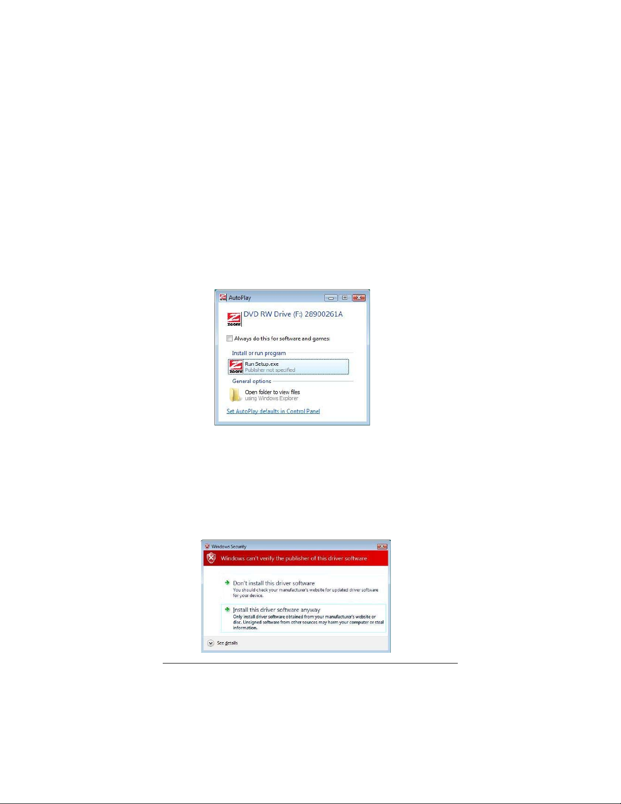
Windows Vista:
If the AutoPlay dialog box appears, click Run Setup.exe:
If the User Account Control dialog box appears, click Allow.
4 Follow the prompts to install the X6v.
Windows Vista: If a message tells you that Windows can't verify
the publisher of the driver software, select Install this driver
software anyway.
Chapter 1: Installation Instructions
10
Page 11
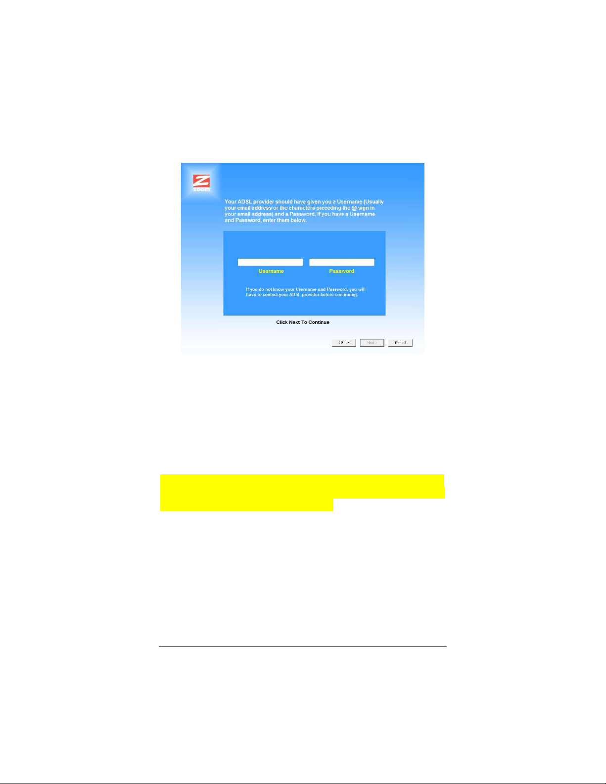
If you are prompted to enter your user name and password,
remember that they are case-sensitive:
5 When you complete the installation and setup, click Finish to
update your modem and close the Install Assistant.
Congratulations! You have established communication and your
computer is now connected to the Internet.
If you want to connect other computers to the X6v, continue with
Setting Up a Network starting on page 19.
If you want to configure a VoIP account, first set up a network -- if
desired -- as described on page 19, and then continue with Chapter
4, Setting Up VoIP Service on page xx.
Macintosh and Linux Installation
Windows users: If you did not run the Install Assistant on the CD,
follow these instructions to install the hardware and configure your
X6v.
Chapter 1: Installation Instructions
11
Page 12
Installing the Hardware
1 Shut down and power off your computer.
(This can be any one of the computers that you plan to use
with the X6v
that is closest to your DSL wall jack.)
. In a typical situation, this would be the computer
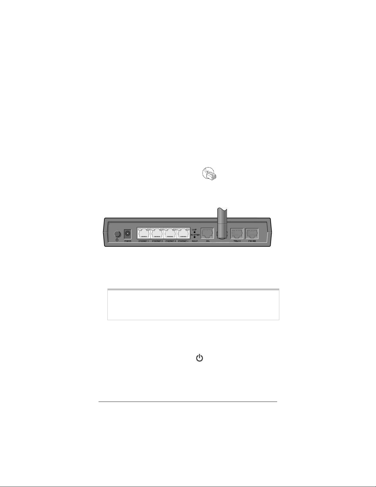
2 Rotate the antenna on the back of the modem to a vertical
position.
3 Connect the modem to the computer’s Ethernet port.
Plug one end of the Ethernet cable
X6v
modem’s ETHERNET ports (Ethernet 1, Ethernet 2,
Ethernet 3, or Ethernet 4) and plug the other end into your
computer’s Ethernet port.
into any one of the
4 Plug the power cube into a power strip or wall outlet and then
plug the power cube’s other end into the modem’s POWER
jack.
Important!
Only use the power cube shipped with the X6v. Other power
cubes may damage your hardware.
5 After you plug in the power cube, the POWER and WLAN
lights on the front panel of the modem should become steady
on, and the INTERNET light should blink. If the POWER
light does not turn on, press the
rear panel and make sure there is power at the wall outlet or
power strip where you plugged in the power cube.
Chapter 1: Installation Instructions
12
button on the modem's
Page 13

6 Turn the computer on.
7 Plug one end of the supplied phone cord into the modem’s
DSL port and the other into the DSL wall jack. The blinking
INTERNET light should become steady on. If it does not,
refer to Troubleshooting on page 125.
Note:
In some countries, including the UK, the modem comes with a
splitter. Plug the splitter into the wall jack with DSL service.
Then plug the supplied phone cord between the modem's DSL
jack and the splitter's MODEM jack.
We recommend that you put an DSL filter on every phone
connected to the DSL phone line. DO NOT put a filter
between the X6v and the wall jack that it is connected to. If
you are using a splitter, you can plug a phone into the splitter's
PHONE jack, which has a built-in filter.
8 If you want to use the modem's VoIP capability, plug a phone
or cordless phone base station into the X6v's PHONE
connector.
If you want to be able to switch between Internet and standard
landline phone service, plug one end of the supplied phone
cord into the X6v's TELCO (i.e., Telephone Company)
connector and the other end into the wall jack where you
would normally plug in a standard telephone.
Congratulations! You have installed the hardware. Now
continue with the next section: Establishing
Communication.
Chapter 1: Installation Instructions
13
Page 14
Establishing Communication
Important!
Macintosh and Linux users must make sure that the computer’s
TCP/IP settings are configured properly BEFORE starting this
section. See Macintosh TCP/IP Settings on page 119 or Linux
TCP/IP Settings on page 121 for instructions.
You must set up the X6v so that it can communicate with your
Internet service provider. To do this, you use the Zoom
Configuration Manager.
1 Close all programs including antivirus software and pop-up
blockers.
2 Log into the Zoom Configuration Manager:
a Open your Web browser and, in its address bar, type
http://10.0.0.2 and then press the Enter key on your
keyboard.
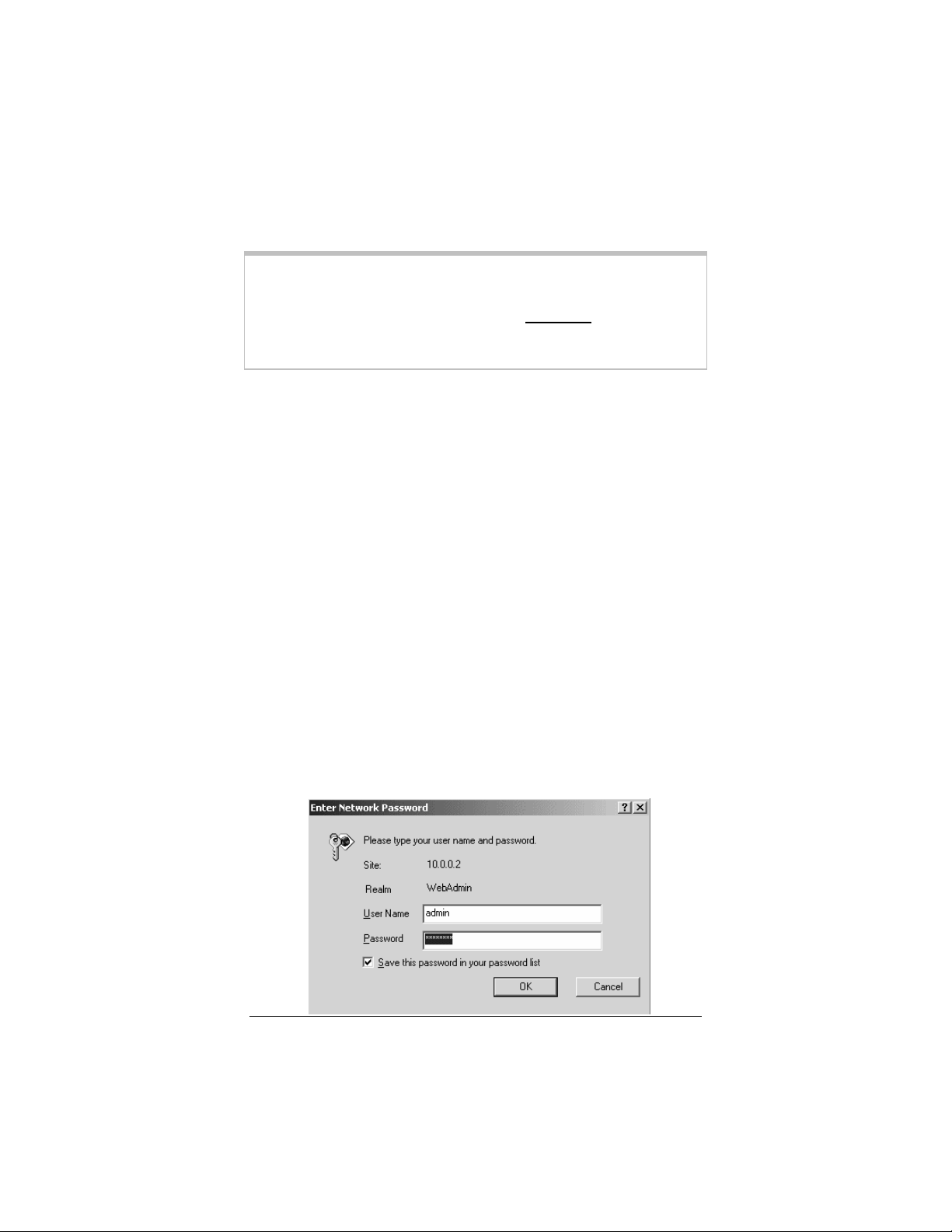
In the Enter Network Password dialog box, type the
following user name and password in lowercase, then click
OK. (The X6v User Name and Password you enter here
are not the same as the User Name and Password that
your Internet service provider may have given you.)
User Name: admin
Password: zoomDSL
Chapter 1: Installation Instructions
14
Page 15
If you are not prompted for a User Name and Password,
do the following in this order: Recheck all connections;
restart the modem and computer; and reset the modem by
inserting a paper clip into the Reset pinhole in the
modem’s back panel and pressing it three times.
Important:
For security, choose your own X6v password after the setup is
complete. See Changing Your Password on page 107.
3
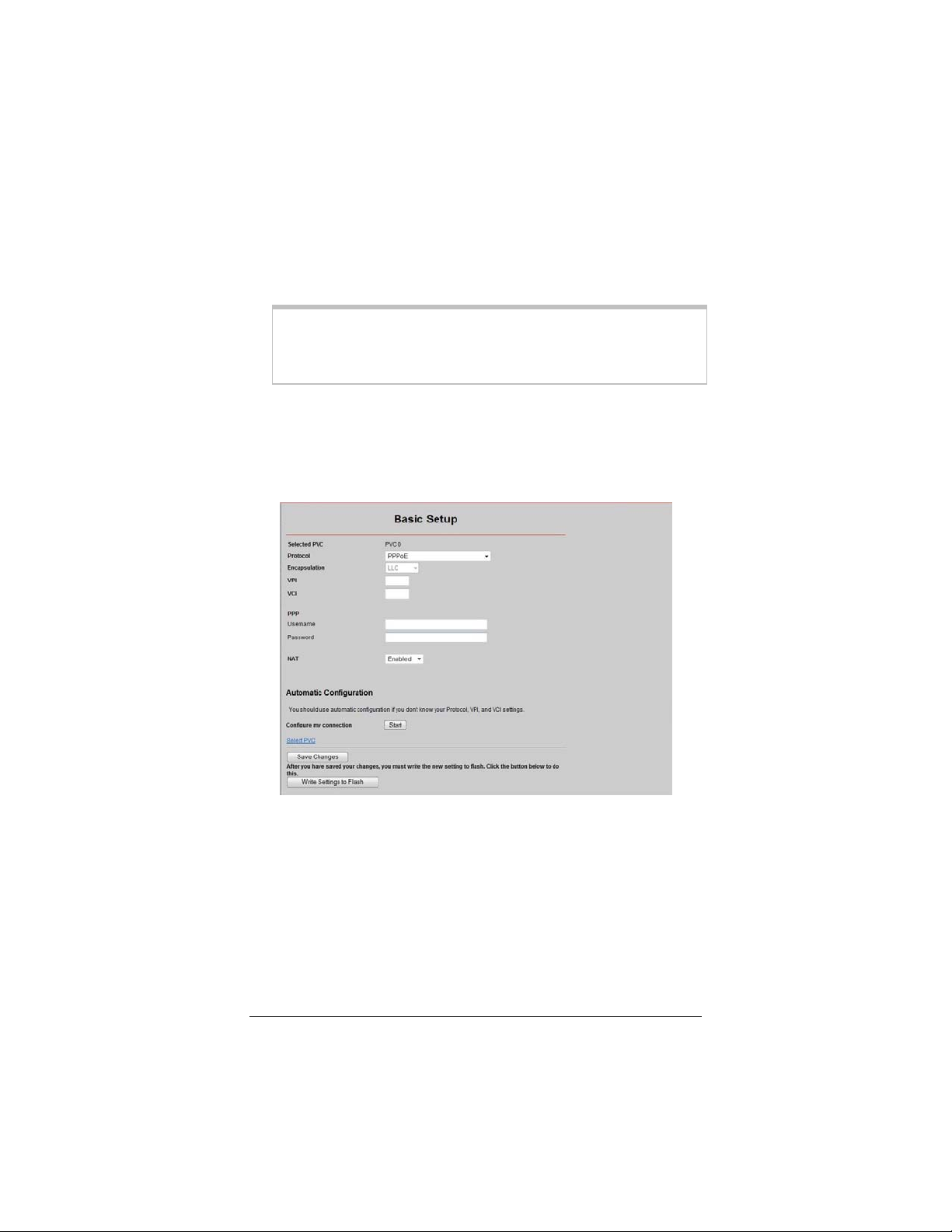
3 After you log in, use the Basic Setup page to configure the
modem so it can connect with your Internet service provider.
• To use Automatic Configuration (recommended):
a At Configure my connection, click Start.
b In the "Settings successfully detected" message box,
click OK to return to the Basic Setup page.
c If the X6v finds a PPPoE or PPPoA connection, on
the Basic Setup page enter the user name and
password given to you by your Internet Service
Provider.
Chapter 1: Installation Instructions
15
Page 16

If the X6v finds a 1483 Bridged or 1483 Routed
connection, you have the option of using either
dynamic or static IP addressing. Depending on your
situation, select the appropriate option button:
− [MOST USERS] Ensure that Obtain an IP
address Automatically is selected if you are
using Dynamic Host Configuration Protocol (also
known as DHCP or dynamic IP addressing). This
option is selected by default because most Internet
service providers use DHCP.
− Select Use the following IP Address only if you
are using a static IP address. (You should know if
you are using static IP addressing. There is
typically an extra charge for a static IP address and
you usually have to make special arrangements
with your Internet service provider to get one.)
Then enter the IP Address, Subnet Mask,
Default Gateway, and DNS that you plan to use.
Click the Save Changes button, then click the
Write Settings to Flash button.
• To configure your settings manually if Automatic Configuration does
not work, follow these instructions:
a On the Basic Setup page, enter your Protocol,
Encapsulation, VPI, and VCI settings in the
appropriate boxes. Your service provider should
supply these values. If you do not know these settings,
refer to the tables starting on page 111.
b NAT (Network Address Translation) is Enabled by
default. This feature lets multiple users access the
Internet sharing a single IP address. Enabled is
typically the right setting. Select Disable in the
unlikely event that you want to assign different public
IP addresses to each network user.
c Depending on the Protocol setting you selected the
bottom half of the page will change so that you can
enter additional information.
If you selected PPPoA or PPPoE, enter your
DSL Username and Password in the appropriate
boxes. Your Internet service provider should have
Chapter 1: Installation Instructions
16
Page 17

given this information to you. (Your Username is
typically your email address or the characters
preceding the @ sign in your email address. This
is NOT the same Username and Password that
you used earlier to open the Zoom
Configuration Manager.)
Chapter 1: Installation Instructions
17
Page 18

If you selected 1483 Bridged or 1483 Routed,
you have the option of using either dynamic or
static IP addressing. Depending on your situation,
select the appropriate option button:
− [MOST USERS] Ensure that Obtain an IP
address Automatically is selected if you are
using Dynamic Host Configuration Protocol
(also known as DHCP or dynamic IP
addressing). This option is selected by default
because most Internet service providers use
DHCP.
− Select Use the following IP Address only if
you are using a static IP address. (You should
know if you are using static IP addressing.
There is typically an extra charge for a static
IP address and you usually have to make
special arrangements with your Internet
service provider to get one.)
Then enter the IP Address, Subnet Mask,
Default Gateway, and DNS that you plan to
use. Click the Save Changes button, then
click the Write Settings to Flash button.
4 Verify that you Internet connection is working. Open your
Web browser (for instance, Internet Explorer or Netscape
Navigator) and try to connect to a familiar Web address. If you
connect successfully, you are ready to set up the rest of your
network.
(If you do not connect, see Appendix D on page 125).
Tip!
If you configured the X6v using a notebook computer, you can
keep it plugged in or you can disconnect it from the unit’s
ETHERNET port. As long as the X6v remains plugged into an
DSL wall jack and a power source, the X6v can function as a
stand-alone device. You can then make the notebook part of your
wireless network.
Chapter 1: Installation Instructions
18
Page 19

Congratulations! You have established communication and your
computer is connected to the Internet.
If you want to connect other computers to the X6v, continue with
Setting Up a Network below.
If you want to configure a VoIP account, first set up your network
-- if desired -- and then continue with Chapter 4, Setting Up
VoIP Service on page 37.
Start here
January 22
Setting Up a Network
Once a computer that is directly connected to the X6v modem is
able to browse the Web, you know for certain that your Web
connection is working. Now you can set up the rest of your
network.
It is up to you whether you want to have some computers
connected directly to the X6v
supports both wired and wireless connections. You can have
X6v
up to 253 connections, four of which can be wired directly through
the
X6’s four ETHERNET ports. You can also plug a network
device (such as a hub, switch, or router) into one of the
ETHERNET ports.
To set up your network, you can do any or all of the following, in
any order that you choose:
• If you want to connect additional computers directly to the
X6v
, see To Connect Additional Wired Computers below.
• If you want to connect a hub, switch, or router directly to the
, see To Connect a Network Device on page 20.
X6v
• If you want to connect additional computers using a wireless
network, see Chapter 2: Setting Up Your Wireless Network
on page 23.
and others connected wirelessly. The
To Connect Additional Wired
Computers
You can connect up to four computers that have Ethernet ports
directly to the X6v
Chapter 1: Installation Instructions
.
19
Page 20

1 Shut down and power off the computer you want to connect
to the X6v
locate the correct IP address for the modem. This is done
when the computer is turned back on in step 3 below.)
.(This is important because the computer must
2 Plug one end of an Ethernet cable into one of the modem’s
ETHERNET ports and plug the other end into the computer’s
Ethernet port.
3 Turn on the computer.
4 Verify that your Internet connection is working. Open your
Web browser (for instance, Internet Explorer or Netscape
Navigator) and try to connect to a familiar Web address.
5 Repeat steps 1–4 for each computer you want to add.
To Connect a Network Device
You can use one of the ETHERNET ports on the X6v to plug in
a network device (for example, a hub, switch, or router).
1 Plug one end of an Ethernet cable into one of the modem’s
ETHERNET ports and the other end into the network
device’s Ethernet port. (For a hub or a switch, this is typically
called an Uplink or Expansion port. For a router, this is
typically called a WAN port.)
2 Set up your network. Refer to the documentation provided
with your particular network device for instructions on how to
do this.
3 Once your network is set up, reboot any computer that is part
of the network.
4 Verify that your Internet connection is working. Open the
Web browser (for instance, Internet Explorer or Netscape
Chapter 1: Installation Instructions
20
Page 21

Navigator) on each computer and try to connect to a familiar
Web address.
{There appears to be no discussion of setting up Static IP
Addresses on the LAN side of the X6v in this document.
There is a help page on the X6v that describes how to set the
ATA portion of the device to a static IP first when the X6v’s
LAN-side DHCP server is disabled. Possibly this is sufficient,
but possibly we should place a note here that warns of this
issue—HV}
Congratulations! You have set up your wired devices. If you
have wireless devices that you want to add to your network, go to
Setting Up Your Wireless Network on page 23.
Chapter 1: Installation Instructions
21
Page 22

Universal Plug and Play
The X6v supports Universal Plug and Play (UPnP™). This means
that other devices plugged into your computer or network (for
example, a gaming application, router, or stand-alone firewall) that
use UPnP should automatically detect the X6v
needed configurations for them to work together. There is no
setup for you to do.
and make the
If You Need Help
Zoom has many Technical Support services available to its
customers. You can access these services in a variety of ways:
• Visit our Web site at www.zoom.com and select Technical
Support. From there, you can register your X6v and/or
contact our technical support experts and/or use our
intelligent database SmartFacts
information.
Tip:
From time to time, Zoom may release improved firmware.
This is also available at www.zoom.com, along with upgrade
instructions. We recommend that you check our Web site
periodically for updates.
• Call our support office. The appropriate number depends on
your country:
US: (561) 241-7170
UK: 0870 720 0090
Other country (US number): (561) 997-9683
• Some retailers of Zoom products provide support or can
recommend a convenient support center.
tm
and/or get warranty
Chapter 1: Installation Instructions
22
Page 23

2
Setting Up Your Wireless
Network
This chapter discusses how to set up a wireless
network using computers that have built-in wireless
capabilities and/or a wireless adapter. Chapter 3
provides information about implementing network
security.
Note that for each computer added to your wireless network, you
will need to take appropriate steps for setting up that computer. To
do that, select one of the three possibilities for that computer
below:
1. Some newer Windows Vista and XP notebooks and desktops
have built-in wireless networking capabilities and do not
require the installation of a wireless component. If this is the
case, you should set up that computer’s wireless connection
using the Windows Vista or XP connect utility. See the
sections below on connecting Windows Vista (page 25) or XP
(page 27) computers with built-in wireless capabilities.
Tip!
To see if your notebook has built-in wireless capabilities: On
the Windows desktop, click Start, click Connect to and then
locate the Wireless Network Connection option. If Connect
to does not appear, or if there is no wireless network available,
then your notebook does not have wireless capabilities.
2. Some desktop and notebook computers may have built-in wireless
networking capabilities, but do not use the Windows Vista or XP
Chapter 2: Setting Up Your Wireless Network
23
Page 24

utility to configure their device. If this is so, set up your computer’s
wireless connection using the instructions on page 28 for
Connecting a Wireless-enabled Computer to the X6v.
Chapter 2: Setting Up Your Wireless Network
24
Page 25
3. Some desktop and notebook computers may need a wireless
network adapter installed. This can be a USB adapter, PC Card
adapter, or PCI adapter. When you install the adapter, make
sure that it is set to infrastructure or access point mode
(NOT ad-hoc or peer-to-peer mode). If you need help
installing your wireless adapter or setting its mode, refer to the
documentation that came with it. After you install the adapter,
see Connecting a Wireless-enabled Computer to the X6v
on page 28.
Connecting a Windows Vista
Computer with Built-in Wireless
Capabilities
1 From the Start menu select Connect to.
2 In the Connect to a network dialog box, highlight the desired
network and click Connect.
• If your desired network is secured, in the next dialog box
enter the security key or password and click Connect.
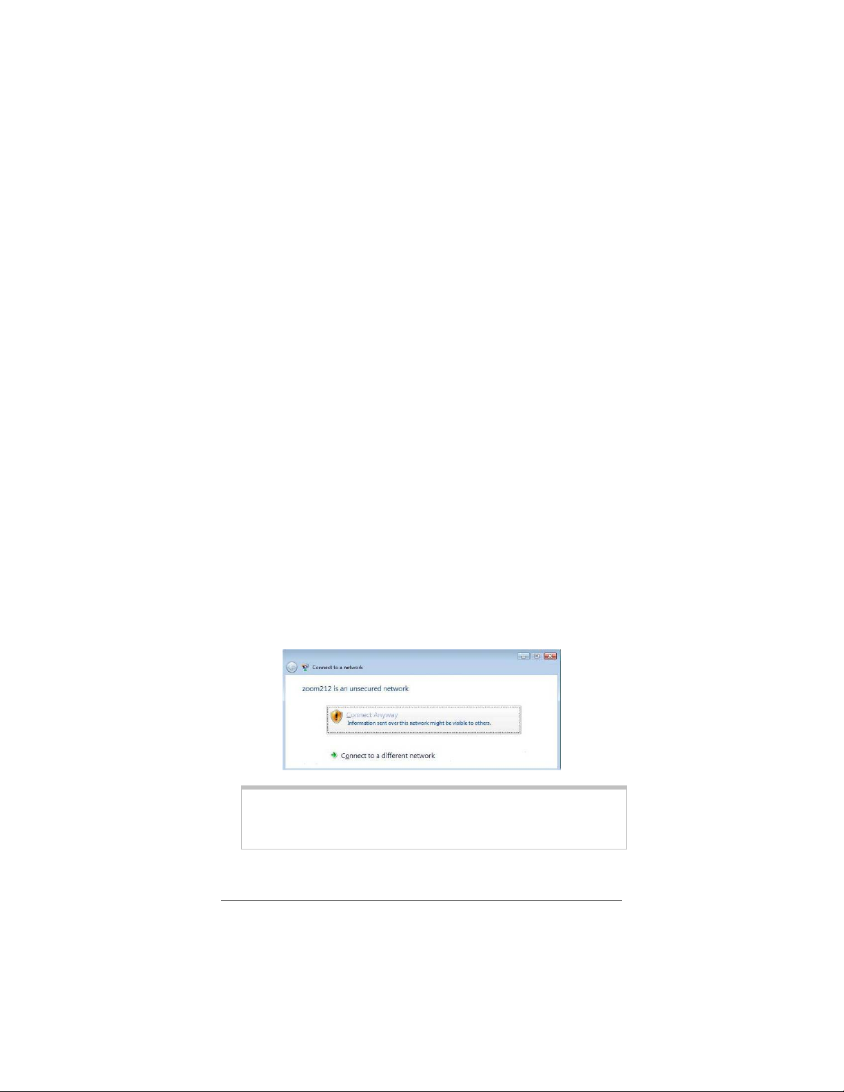
• If your desired network is unsecured, in the message box
select Connect Anyway.
Note: We strongly recommend that you set up a secured
network. For information on wireless security, see Setting
Wireless Security on page 31.
If you have difficulty connecting, make sure you have entered
the correct password. Then perform a power cycle on your
Chapter 2: Setting Up Your Wireless Network
25
Page 26

computer and the X6v as described in the Troubleshooting
Tips on page 125.
3 In the Successfully connected to [desired network] dialog
box, you have three options. You can:
• Select Save the network and Start this connection
automatically if you always want to connect to the same
network. Then click Close. The next time you start your
computer you will automatically connect to the selected
network.
• Select Save the network and clear the Start this
connection automatically check box if you don't want to
automatically connect to this network every time you start
your computer but you will want to connect in the future.
Click Close to display the Select a location . . . dialog box
where you choose a location. Windows Vista automatically
applies the correct network security settings.
If the User Account Control dialog box appears, click
Continue.
• Click Close to complete the connection procedure. Select
this option if you are connecting to this network only one
time.
To disconnect from the current network:
1 From the Start menu, select Connect to.
2 In the Disconnect or Connect to another network dialog
box, select the current network and click Disconnect.
3 In the Are You Sure? message box, click Disconnect again.
4 In the next dialog box, you can connect to another network or
click Close to complete the disconnect procedure.
Chapter 2: Setting Up Your Wireless Network
26
Page 27

Connecting a Windows XP
Computer with Built-in Wireless
Capabilities
1 On your Windows desktop, click the Start button then click
Control Panel.
2 Double-click the Network Connections icon.
3 Right-click the Wireless Network Connection icon, then
select Properties.
4 On the Wireless Network Connection Properties dialog
box, select the Wireless Networks tab. Windows will
automatically scan for available wireless networks in your area.
Any compatible networks within range will appear in the
Available networks list. It should find the wireless network of
X6—named zoom. (The scan is done automatically
the
because the Use Windows to configure my wireless
network settings check box is selected by default).
5 Select zoom from the Available networks list, then click the
Configure button to add it to the Preferred networks list.
The notebook will try to connect to the Internet using the
wireless networks listed here, in the order in which they
appear. (If you already have networks listed here, we
recommend you either remove them or use the Move up
button to move zoom to the top of the list.)
6 Click OK.
7 Test your wireless connection. From the computer or
notebook that you set up, open your Web browser (for
instance, Internet Explorer or Netscape Navigator) and try to
connect to a familiar Web address.
If you connect successfully, your notebook’s wireless
capability is configured and you are ready to browse the Web!
Chapter 2: Setting Up Your Wireless Network
27
Page 28

Important!
If you want to add security to your network, please see Setting
Wireless Security on page 31.
Connecting a Wireless-enabled
Computer to the X6v
1 Go to the wireless-enabled computer that you want to add to
the network. The computer should have software that will let it
perform a site search to scan for available wireless networks
in your area. When the SSID (Service Set Identifier) of your
wireless network appears in the list—the SSID is zoom—
X6v
select it as the network you want to use to connect to the
Internet.
Tip!
For most wireless adapters, you will use its wireless
configuration manager software and click a Scan button or
select a Site Scan, Scan Networks, or other similarly named
tab to do a site search. If you need help, refer to the
documentation that came with your wireless adapter.
There are several site scan issues you should be aware of:
¾ If you installed a wireless adapter on a Windows XP
computer, Windows XP may try to automatically configure
the adapter (rather than let you use the software provided
with the wireless adapter). You will know this is happening
because you will be prompted with a message about one or
more wireless networks being available. You will also be
able to click a link to open the Wireless Network
Connection Properties dialog box. If this happens, click
the link, clear the Use Windows to configure my
wireless network settings check box, and then click OK.
You can then use the software provided with your wireless
adapter without interruption from Windows.
Chapter 2: Setting Up Your Wireless Network
28
Page 29

¾ More than one wireless network may appear in the list.
These are other wireless networks that are within range of
your network. Your neighbors, for instance, may be within
range of your network. Each wireless network has a
channel associated with it. We recommend there be at least
a five-channel difference between your network and those
of your neighbors. Having less than a five-channel
difference may result in interference with your connection.
By default, the X6v
this channel, you must do so using the Wireless Setup
page of the Zoom Configuration Manager.
¾ If you want to secure your wireless network so it won’t be
accessible by others, you should specify security settings.
To learn how, see Setting Wireless Security on page 31.
(By default, the wireless connections provided by the X6v
do not have any security applied.)
uses channel 10. If you need to change
2 Test your wireless connections. From each desktop or
notebook computer that you set up, open your Web browser
(for instance, Internet Explorer or Netscape Navigator) and try
to connect to a familiar Web address.
If you connect successfully, you are ready to browse the Web!
Important!
To add security to your network, see Setting Wireless Security on
page 31.
Chapter 2: Setting Up Your Wireless Network
29
Page 30

Checking Your Settings
If you ever need to check your wireless settings, you can do so
from the Wireless Setup page. This page is available in the Zoom
Configuration Manager by clicking the Wireless icon.
The table below explains the settings:
This setting… Lets you specify…
Wireless Status Enable shows that your wireless network is up.
Disable indicates that your wireless network is
down.
SSID
Hide SSID
Default Channel
Profile
Encryption
Region If your country is not listed, select Other.
The Service Set Identifier for your wireless network.
By default, the SSID for the
change the SSID to any name that you want.
Set to true if you do not want to broadcast the SSID
of your network.
The channel your wireless connection uses by
default for your wireless connection. The
comes set for channel 10.
The standard used by your wireless adapters. This
drop-down list contains 802.11b Only, 802.11g
Only, or Mixed Mode.
The default is Mixed Mode, which allows you to
mix both b and g wireless adapters.
The type of encryption used for your wireless
Internet signal. This drop-down list contains None,
WEP-64 bit, WEP 128 bit, WPA and WPA2.
The default is None, meaning that no security is
enabled.
X6v is zoom. You can
X6v
Chapter 2: Setting Up Your Wireless Network
30
Page 31

3
Setting Wireless Security
When you first set up your X6v wireless network, security is
turned off by default. This means that your wireless signal is
not encrypted and that anyone with compatible wireless
technology can access your computer network and the
Internet using your wireless connection. This chapter
explains how to set up wireless security to protect your
network and Internet connection.
Overview
To set up wireless security, you will create and enter a unique
passphrase or an alphanumeric key. Once entered, only devices
with the proper key or passphrase will be allowed to establish a
connection to the network.
There are two basic ways to configure and implement a passphrase
or key. They are WPA (WiFi Protected Access) or WPA2 and
WEP (Wired Equivalent Privacy) 64 and 128 bit). WPA2 is best,
but you can use it only if all your wireless devices support the
802.11g profile.
You can check to see if all other clients that you plan to put on the
network support WPA2 or WPA. You can do this by checking the
manual that came with each device or by checking the
configuration software for the installed device. Look under
Security or Encryption or Setup or Advanced Features. If all
the clients support WPA2 or WPA, proceed with Setting Up
Security Using WPA2 or WPA. If they do not, skip to Setting
Up Security Using WEP.
Chapter 3: Setting Wireless Security
31
Page 32

Chapter 3: Setting Wireless Security
32
Page 33

Setting Up Security Using WPA2
or WPA
WPA2 and WPA use a passphrase that you choose and enter on
the X6v and other wireless devices on the network (clients) to set
up security. To use WPA2 or WPA, all of the wireless devices on
your network must support that encryption method.
1 Check to see that all other clients that you plan to put on the
network support WPA2 or WPA. If they do not, skip to
Setting Up Security Using WEP.
2 Click the Wireless icon in the Zoom Configuration
Manager. This will open the Wireless Setup page. Go to
Encryption (which should say None) and select WPA2 or
WPA from the drop-down menu. A new fill-in box labeled
WPA Passphrase will open directly below the Encryption
box.
3 Choose and enter a Passphrase. You can enter a word or
phrase, or for greater security you can enter a combination of
Chapter 3: Setting Wireless Security
33
Page 34

numbers and letters. The Passphrase is case-sensitive and can
be up to 8 characters.
4 Every wireless network client needs to be set individually by
entering the Passphrase on all wireless devices on the
network. Open the software that came with the device, which
should be running on the computer where the device is
installed. Find the configuration menu for security, choose
WPA2 or WPA, and enter the Passphrase, exactly as you
entered it on the X6v
Your security setup configuration is now complete!
Setting Up Security Using WEP
If all of your network devices DO NOT support WPA2 or WPA,
you can use WEP to configure network security. WEP can be
configured two ways: 64-bit and 128-bit. 128-bit WEP provides a
bit more security than 64-bit, but 128-bit WEP also tends to
diminish network performance. We recommend that most people
configure their WEP for 64-bit security.
Wireless Setup page.
1 Click the Wireless icon in the Zoom Configuration
Manager. This will open the Wireless Setup page. Go to
Encryption (which should say None) and select WEP-64 bit
(or WEP-128 bit for more security, but diminished network
performance) from the drop-down menu. Six new boxes open
directly below the Encryption box.
Chapter 3: Setting Wireless Security
34
Page 35

2 Check the box marked Passphrase and then choose and enter
a Passphrase. You can enter a word or a phrase, or for greater
security you can enter a combination of numbers and letters.
The Passphrase is case-sensitive and can be up to 8 characters.
If ALLof the wireless devices (clients) on the network are Zoom
devices, go to step 3. If some or all or the devices are not Zoom
devices, go to step 4.
3 If ALL of the wireless devices (clients) on the network are
Zoom devices, you need to enter the Passphrase that you
just entered for each device.
Every wireless network client needs to be set individually.
Open the software that came with the device, which should be
running on the computer where the device is installed. Find the
configuration menu for security, choose WEP, and enter the
Passphrase, exactly as you entered it on the X6v
Setup page.
Your security setup configuration is now complete!
Wireless
Chapter 3: Setting Wireless Security
35
Page 36

4 If any or all of the other wireless devices on the network
(clients) are not Zoom devices, you will enter one of the
keys shown below the Passphrase on each client. You must
enter the same key for each device. The key that you must use
is the key corresponding to the Default Key number shown. If
the number in the default key box is 1, use Key 1, and so on.
You can choose the default key you prefer using the pull-down
Default Key menu box.
Now that you have a key, enter it for each client. Every
wireless network client needs to be set individually. Open the
software that came with the device, which should be running
on the computer where the device is installed. Find the
configuration menu for security, choose WEP (64-bit or 128-
bit depending on what you selected), and enter the Default
Key, exactly as it appears on the X6v
Wireless Setup page.
Your security setup configuration is now complete!
Chapter 3: Setting Wireless Security
36
Page 37

1/21/08: These are Hume's
edits.
4
Setting Up VoIP Service
This chapter covers the setup of the X6v for Internet
telephone service, using the X6v’s built-in VoIP
capabilities.
To complete the installation, you need the following:
• An account set up with a VoIP service provider. If your X6v did not
come with an account set up, follow the instructions below, Using
the Zoom Configuration Manager to set up VoIP service. You will
need to go to your service provider’s Web site and sign up for
service if you have not already done so.
• A telephone so you can place and receive phone calls.
Using the Zoom Configuration
Manager to set up VoIP service
• The Zoom Configuration Manager can be accessed from
your Web browser. You can use this to set and monitor VoIP
features. Some of these features can also be set by using your
telephone keypad.
Quick Setup of a Zoom X6v for
Use with a SIP VoIP Service
5 Log into the Zoom Configuration Manager:
Page 38

{It’s a little strange to introduce the Configuration Manager here,
but someone who installed their X6v using the Wizard, and did not
configure wireless security, would not have encountered the
Configuration Manager up to this point—HV}
b Open your Web browser and, in its address bar, type
http://10.0.0.2 and then press the Enter key on your
keyboard.
b In the Enter Network Password dialog box, type the
following user name and password in lowercase, then click
OK. (The X6v User Name and Password you enter here
are not the same as the User Name and Password that
your Internet service provider may have given you.)
User Name: admin
Password: zoomDSL
If you are not prompted for a User Name and Password,
do the following in this order: Recheck all connections;
restart the modem and computer; and reset the modem by
inserting a paper clip into the Reset pinhole in the
modem’s back panel and pressing it three times.
Next, navigate to the Zoom Configuration Manager’s page
called Your VoIP Account. From the home page, click the VoIP
button at the top of the screen. This will bring up a new set of
buttons at the top of the page. Click the button labeled Advanced
VoIP Setup. On the left-hand pane, you will see a contents list.
Click VoIP Accounts. The page called Your VoIP Account will
open.
38
Page 39

To configure your X6v for a SIP account, fill in entries on this
Your VoIP Account page, as required for your service. In most
cases, you need only be concerned with the bolded entries.
Entry What it means
Service
Provider
Outbound
Caller ID
Phone
Number (SIP
User ID)
Auth User
Name
Auth
Password
Provider On This selection enables or disables SIP.
Ring Type You can assign a desired ring type to this
Dial Prefix You can specify a dial prefix for this
This is the name of the service provider
seen when someone logs into this X6v
Set this to send an alphanumeric caller
ID to people called by the X6v
Enter a valid SIP User ID for your VoIP
service
Enter a valid Authorization User ID for
your VoIP service
Enter a valid Authorization Password
for your VoIP service
You can select either SIP to enable or
None to disable SIP for this account.
account. By default, this should be the
standard ring for your country.
account
39
Page 40

Preferred
Codecs
Domain Name Address (URL or IP Address) of your
Auth Domain Enter if this is different from your
Proxy Domain Address (URL or IP Address) of your
Register
Domain
ReReg
Interval
Subscribe
Domain
ReSub
Interval
By default codec negotiation is controlled
by the selection Preferred Codecs under
VoIP Parameters…Audio Settings. In
some cases, you may wish to override
those here.
VoIP service’s domain or realm
service’s Domain Name
service’s SIP proxy server
Address (URL or IP Address) of your
service’s SIP registrar
Time after which your X6v will reregister (in seconds)
Address (URL or IP Address) of your
service’s SIP subscription server
(required if you take advantage of
Zoom’s emergency service event)
Time after which your X6v will resubscribe (in seconds)
After you enter the above items, click the SAVE button at the
bottom of the page. After the X6v confirms the data has been
successfully saved to flash, click the Reboot button to force
registration to the account you have entered.
Now continue below with Other Configuration Settings.
Other Configuration Settings
You may wish to change other parameters as well. For the most
part, these should be self-explanatory as you navigate through the
Zoom Configuration Manager. Some popular items are:
To change codec priority (note that if you want to force use of
a low-bandwidth codec, you should remove the highbandwidth entries):
VoIP Parameters…Audio Settings
Preferred Codecs
To add emergency numbers that are used in your area:
Subscription Services…Emergency Services
Default emergency numbers routed via VoIP
Chapter 5: The X6v and Online Gaming
40
Page 41

Default emergency numbers routed via the PSTN
To modify dialing behavior (for example, with respect to
national numbers, etc.):
Subscription Services…Operating Mode
Ipbx input pattern voip cfg
Ipbx input pattern pstn cfg
To send local numbers to the PSTN:
Basic button at top of page…X6v Express Setup
Non-VoIP calls
Chapter 5: The X6v and Online Gaming
41
Page 42

In each case, click SAVE after you have made the changes you
wish to make. You do not generally need to click Reboot in order
for changes to take effect, unless you have made a change to an IP
Address. This latter requires the SIP stack to restart, which is
accomplished by executing a reboot.
Now continue below with Firmware Upgrades.
Firmware Upgrades
The X6v is shipped with the latest firmware as of the shipment date.
However, fresher code may have become available since shipment.
You have two options for firmware upgrades:
1. Your X6v can be automatically updated with the latest
firmware or
2. We can notify you via email when a firmware upgrade is available,
and you can decide whether to use the upgrade.
If you would like your X6v to be automatically updated to the latest
code version, you can do this by registering to receive updates at
www.zoom.com/ata_update. After registering, your X6v will
automatically look for the newest firmware via the Internet
whenever you power up the device. If you later decide you no
longer want to receive automatic updates, you can return to the
registration page and cancel your request.
If you would like Zoom to notify you via email when a firmware
upgrade is available, please sign up for this free service at
www.zoom.com/ata_update
.
{Need a heading here at a minimum, and possibly this section
should be placed at the top of this chapter—HV}
Now you’re ready to connect a telephone to the X6v. You will
make your connections to the back of the X6v.
1 Plug your telephone or cordless phone base station into the X6v’s PHONE
jack, which is on the far right of the X6v’s back panel.
Note: In some countries outside the USA, you may need to use a phone-jack adapter. Plug the adapter
into the X6v’s PHONE jack and then plug in your phone.
2 If your unit has the word TELCO on the front panel of the unit, continue
with step 3.
Chapter 5: The X6v and Online Gaming
42
Page 43

If your unit does not have the word TELCO on the front panel, continue
with step 4.
3 For X6v units with a TELCO jack: Plug one end of the supplied telephone
cord into the X6v’s TELCO jack and the other end into your home or
office’s telephone jack, one where you would normally plug in a standard
telephone. You may need to use a phone-jack adapter. If you have DSL
service at that wall jack, you need to put an DSL filter between that jack and
the X6v’s TELCO jack. Now continue with step 4.
4 Make sure the READY light is on in the VoIP area of the X6v’s front panel.
If it is, you’re ready to make phone calls. Congratulations! If the READY
light is not on, wait a few minutes and then recheck all VoIP account
settings.
Making Phone Calls – The Basics
How you use the phone plugged into your X6v depends on the
answer to this question: Does your X6v have a TELCO jack
plugged into a phone jack with normal phone service?
• If it does not: When you dial, the digits you dial will normally
be passed to your VoIP service provider. Please remember that
even local calls need an area code.
• If it does: You can dial calls that first travel through the
Internet, or you can dial calls that first travel through your
normal telephone service by way of your TELCO jack. Your
X6v can be set up by your service provider, for instance, to
route all calls through the Internet unless those calls are local
or emergency calls. You can also force a call to go one way or
the other:
If you come off-hook and dial #8 then additional digits
will be dialed into your normal telephone service.
If you come off-hook and dial #9 then additional digits
will be dialed through the Internet.
If your X6v loses power, you can dial through your normal telephone service
as if you had a phone plugged directly into a phone jack.
If the X6v loses power or loses its Internet connection, you cannot place calls
through the Internet.
Chapter 5: The X6v and Online Gaming
43
Page 44

Advanced Features - Controlling
the X6v from Your Phone
Your X6v has a number of features that relate to calls traveling
through the Internet. These features can be controlled from the
phone plugged into your X6v as described below. For all these
commands you first take the phone off-hook and then enter
the command.
*55 Enable call waiting on all calls. When a call is waiting,
you will hear a tone. You can then do a hook-flash to go
back and forth between your 2 callers.
*56 Disable call waiting on all calls.
*59 Disable caller ID for call waiting calls.
*70 Turn off call waiting for the next call.
*71 Turn on call waiting for the next call.
*72 Forward all calls to <phone number> After you dial *72, dial 8, enter
the phone number, then press #.
*73 Disable call forwarding.
*82 Enable caller ID for all outbound calls.
*62 Block caller ID on all outbound calls.
*65 Enable caller ID on all inbound calls.
*85 Disable caller ID for all inbound calls.
*67 Enable caller ID for the next outbound call.
*68 Block caller ID for the next outbound call.
*66 Redial the last number you dialed.
*69 Call the last person who called you.
*77 Block all calls that don’t have a caller ID.
*87 Stop blocking calls that don’t have a caller ID.
*78 Do not disturb. Your phone won’t ring!
*79 Turn off “Do not Disturb.” Lets your phone ring.
Chapter 5: The X6v and Online Gaming
44
Page 45

The commands above let you use a phone to directly control the
X6v. Some VoIP service providers also let you control some of
these features by using the setup screens for your account.
Note also that these features apply only to VoIP calls, not calls that
travel through the traditional phone network by way of your
TELCO jack. Features for the traditional phone network are
normally available from your traditional phone company.
Resetting Your X6v
To reset the X6v to your most recently saved configuration, put the
end of a pin or paper clip into the VoIP RESET hole (the top one
of two reset holes) in the back panel and hold the button down for
5 seconds or more.
To restore the X6v to the most recent settings given to you by your
service provider, press and hold the VoIP RESET button for 5
seconds or more, release the button, and then press and hold for at
least 5 more seconds.
Chapter 5: The X6v and Online Gaming
45
Page 46

5
The X6v and Online Gaming
This chapter covers the set up of the X6v for online
gaming with a desktop, notebook, Xbox® Live, or
Playstation® 2.
Do I Need to Do Anything?
There are three cases where you need to set up your modem in
order to play online games:
• If you are using your computer to play a peer-to-peer or head-
to-head game over the Internet, you always have to set up the
modem unless you linked up to your partner by going to a
Web site. A peer-to-peer game is a game where two players are
competing directly against one another. Popular peer-to-peer
games include Age of Empires, Command and Conquer,
Dark Reign 2, and Unreal Tournament. If you are unsure
whether your game is a peer-to-peer game, check the game
instructions.
Chapter 5: The X6v and Online Gaming
46
Page 47

• If you are using your computer to play a multi-player game
and you want to host the game. Popular multi-player games
include Half Life, Diablo II, Delta Force, Hexen II, Myth,
Quake II, and Warcraft II, III.
• If you are playing an online game using Xbox® Live or
PlayStation® 2.
In all three cases you will need to do the steps described in the
next section, Setting Up the X6v for Online Gaming.
Setting Up the X6v for Online
Gaming
Setting up the X6v for online gaming involves two basic steps:
Choosing an IP Address for Gaming and Setting Up a Virtual
Server or DMZ. This section provides instructions for doing these
tasks on your computer, Xbox®, or Playstation® 2.
Step 1: Choosing an IP Address
for Gaming
You need to make sure that the computer or gaming system you
use for playing games always has the same IP address. By default,
the X6v assigns addresses dynamically (using Dynamic Host
Configuration Protocol or DHCP) to the devices on the local area
network whenever they reboot. Therefore, the addresses won’t
necessarily always be the same. The modem, however, can be set
up to assign the same address to your computer or gaming system
every time.
To ensure that your computer or gaming system always uses the
same address, follow the steps below.
Chapter 5: The X6v and Online Gaming
47
Page 48

1 If you are using Xbox or PlayStation 2, connect the device to
your modem with an Ethernet cable. On your TV screen,
locate Network Settings and select Connect.
2 Click the Advanced Setup icon in the Zoom Configuration
Manager.
Chapter 5: The X6v and Online Gaming
48
Page 49

3 On the Advanced Setup page, click the LAN Configuration
button. Next click the Add DHCP Fixed Host button. The
Create New DHCP Server Fixed Host page appears:
4 Before you can enter an IP address, you need to enter the
MAC (Media Access Control) address of your computer or
gaming system. Follow the next set of instructions for your
gaming system to find the gaming system’s MAC address.
If you are using a computer to play an online
game:
¾ If you know the name of your computer or if you have
only one computer connected, you can find the MAC
address under DHCP Clients at the bottom of the Create
New DHCP Server Fixed Host page. You can also find
the MAC address on the System Status page. Click the
System Status icon and scroll down until you see DHCP
Client Status.
¾ If you do not know the name of your computer or you
have more than one computer connected, follow these
steps to find the MAC address:
a Go to the computer you want to use for gaming.
b Click the Start button and select Run.
c In the Run dialog box, type command and click OK
to open the Command or MS-DOS window.
Chapter 5: The X6v and Online Gaming
49
Page 50

d In the Command Prompt or MS-DOS window
(after C:\> or C:\WINDOWS>), type ipconfig, leave
a space, then type /all
It should look like this: ipconfig /all
e Press Enter. The MAC address is displayed as the 12-
digit Physical Address or Internet Adapter address.
Write this address down and keep it handy.
Now go to Step 5 on page 51 to assign the computer an IP
address.
If you are using Xbox® Live to play an online
game
Follow these steps to find the MAC address on the Xbox
Dashboard:
a Go to the System area of the Dashboard.
b Select Network Settings, then Edit Settings.
c Click the Additional Settings tab and select Advanced
Settings.
You will see a MAC address similar to
0050F24ADC29. Your address will be different.
Write the address down and keep it handy.
Now go to Step 5 on page 51.
If you are using PlayStation® 2 to play an
online game:
a Insert your Network Access Disc into the PlayStation.
b On the main menu, select ISP Setup, then I have an
ISP, then Automatic Configuration.
c On the Select an Internet service provider menu,
select Other.
Chapter 5: The X6v and Online Gaming
50
Page 51

d On the Connection Test menu, select Advanced.
The MAC address is displayed on the Advanced
Broadband Settings screen.
Write the address down and keep it handy. Continue with
Step 5.
5 Now that you have determined the MAC address, you can
assign your computer or gaming system an IP address. On the
Create New DHCP Server Fixed Host page, make these
entries:
Setting Values
IP Address Enter 10.0.0.50. If you are setting up more
than one computer or gaming system, you
should use different IP addresses. For
example, if you are setting up an Xbox
and a computer, enter 10.0.0.50 for the
Xbox, and 10.0.0.51 for the computer.
MAC
Address
Maximum
Lease Time
Type the MAC address from Step 4.
Leave the default setting.
6 Click Save Changes and then Write Setting to Flash to save
the IP address to permanent memory. Now your computer or
gaming system will always be assigned this address.
Chapter 5: The X6v and Online Gaming
51
Page 52

Step 2: Setting Up a Virtual
Server or DMZ
You set up either a virtual server or a DMZ (Demilitarized Zone)
so that the modem’s firewall won’t block the other players from
your system during your gaming. The main difference between the
virtual server and the DMZ is the amount of access someone has
to your system.
A virtual server will allow access to your computer on certain ports.
A port is like a channel that is used by applications (such as games)
to communicate on. For example, the directions for the game you
want to play over the Internet might tell you to open up port 6000.
A DMZ differs from a virtual server in that it allows access on all
ports to the computer. Because of this, DMZ's are less secure than
virtual servers and should be used with caution on your computer.
For Xbox® Live and Playstation®2, a DMZ is OK since security is
not as much of an issue as it is for your computer.
• If you are playing a peer-to-peer or multi-player game on
your computer, go to Setting Up a Virtual Server or DMZ
on Your Computer on page 53.
• If you are using Xbox Live, go to Setting Up a DMZ on an
Xbox® Live page 56.
• If you are using Playstation 2, go to Setting Up a DMZ on a
Playstation® 2 on page 58.
Chapter 5: The X6v and Online Gaming
52
Page 53

Setting Up a Virtual Server or DMZ on
Your Computer
Note:
If you have third-party firewall software, such as the Windows XP
firewall, installed on your computer, you may need to deactivate it
before setting up the virtual server or DMZ. Otherwise your
computer may block the ports you want to open.
1 Click the Advanced Setup icon. Then, click the Virtual
Server/DMZ button to display this page:
2 On the Virtual Server/DMZ page, click the Add Virtual
Server/DMZ link to display the Add Virtual Server/DMZ
page:
Chapter 5: The X6v and Online Gaming
53
Page 54

3 Make the following entries:
Setting Values
Internal IP
Address
Protocol If you know your protocol (udp or tcp)
Start Port
Enter the IP address that you specified on
the Create New DHCP Fixed Host
Server page.
and port number(s) from your game
instructions, select the protocol from the
list.
If you do not know your protocol or port
number(s), you need to set up your
computer as a DMZ by selecting DMZ
from the Protocol list. This will open up all
ports on the computer to all
communication over the Internet.
Warning
protection provided by the DSL Ethernet’s
firewall. We therefore recommend that a
DMZ be used only when necessary.
If you designated your computer as a
DMZ, you do not have to enter anything
here.
If you are playing another peer-to-peer
or multi-player game, your game
instructions should tell you what ports to
enter here. To enter a number, you must
enter tcp or udp in the Protocol box.
If you only need to open one port, enter the
same port number for both Start Port and
End Port. If you need to open a range of
ports, enter the starting port number of the
range here.
The highest supported port number is
65535.
: Setting up a DMZ removes the
Chapter 5: The X6v and Online Gaming
54
Page 55

End Port
If you designated your computer as a
DMZ, you do not have to enter anything
here.
If you are playing another peer-to-peer
or multi-player game, your game
instructions should tell you what ports to
enter here. To enter a number, you must
enter tcp or udp in the Protocol box.
If you only need to open one port, enter the
same port number for both Start Port and
End Port. If you need to open a range of
ports, enter the starting port number of the
range here.
The highest supported port number is
65535.
4 Click Save Changes and then Write Settings to Flash.
Your set up is complete!
Chapter 5: The X6v and Online Gaming
55
Page 56

Setting Up a DMZ on an Xbox® Live
1 Click the Advanced Setup icon. Then, click the Virtual
Server/DMZ button to display this page:
2 On the Virtual Server/DMZ page, click the Add Virtual
Server/DMZ link to display the Add Virtual Server/DMZ
page:
3 Make the following entries:
Setting Values
Internal IP
Address
Protocol Select DMZ to enable your Xbox as a
Start Port The field remains unavailable because you
End Port The field remains unavailable because you
Chapter 5: The X6v and Online Gaming
56
Enter the IP address that you specified on
the Create New DHCP Fixed Host
Server page.
DMZ.
selected DMZ. No entry is required.
selected DMZ. No entry is required.
Page 57

4 Click Save Changes and then Write Settings to Flash.
5 Update the Xbox Dashboard:
Make sure you have your Xbox Live Starter Kit at hand. Insert
the Xbox Live CD into your Xbox. Once the update is
complete, the main menu will include a Xbox Live entry.
6 Insert the Xbox Communicator module into the Xbox
Controller expansion slot (top slot). Then insert the headset
plug into the Communicator module.
7 Activate your Xbox Live account:
The Xbox Live CD should still be in your Xbox. We
recommend that you watch a video that explains the
installation process: Select Xbox Live from the menu. Then
from the Dashboard, select Xbox Live and follow the
prompts. Note: You will need your subscription code to
activate your account—this number is located on the CD’s
sleeve. (If you require more detailed instructions, please refer
to your Xbox Live documentation.)
Your setup is complete!
Chapter 5: The X6v and Online Gaming
57
Page 58

Setting Up a DMZ on a Playstation® 2
1 Click the Advanced Setup icon. Then, click the Virtual
Server/DMZ button to display this page:
2 On the Virtual Server/DMZ page, click the Add Virtual
Server/DMZ link to display the Add Virtual Server/DMZ
page:
3 Make the following entries:
Setting Values
Internal IP
Address
Protocol Select DMZ to enable your Playstation as a
Start Port The field remains unavailable because you
End Port The field remains unavailable because you
Enter the IP address that you specified on
the Create New DHCP Fixed Host
Server page.
DMZ.
selected DMZ.
selected DMZ.
4 Click Save Changes and then Write Settings to Flash. Your
setup is complete!
Chapter 5: The X6v and Online Gaming
58
Page 59

6
Using Advanced Setup
Advanced Setup is primarily for technically advanced
users. For most people, the options that are set by
default when the
X6v is installed are sufficient.
However, those who want or need to change the
settings can do so using the Advanced Setup page in
the Zoom Configuration Manager. This chapter
explains the advanced options and features of the
X6v modem and how to apply them to your network.
The information in this chapter applies to you if:
• Your Internet service provider instructs you to
enable, disable, or change the default settings for
X6v
your
• You need to change your Wide Area Network
settings
• You want to change the default firewall settings to
block particular IP addresses and intrusive hosts
• You want to change your DSL password
• You have customized your configuration and
want to back it up for future use or apply it to
additional modems
• You want to set up fixed IP addresses for your
computer(s)
X6v
Chapter 6: Using Advanced Setup
59
Page 60

Note: Users who want to set up Quality of Service
(described in this section) can do so more easily using
the Zoom Install Assistant.
Chapter 6: Using Advanced Setup
60
Page 61

Viewing the Advanced Setup
Options
You open the Advanced Setup page by clicking the Advanced
Setup icon at the top of the Zoom Configuration Manager. The
page opens and displays buttons organized into three groups:
Configuration, Status, and Administration:
Configuration Options
When you click a Configuration button, a page opens to the
option you selected. The following table describes each option and
the tasks you can perform.
This button… Opens a page that lets you…
WAN
Configuration
Chapter 6: Using Advanced Setup
Specify how the Wide Area Network (WAN) DSL
setup is configured. Some of the values need to
be supplied by your ISP/DSL provider.
61
Page 62

This button… Opens a page that lets you…
Firewall
Define an additional layer of security for the
computers in your network. For example, if you
create a DMZ interface using the Virtual
Server/DMZ page (see below), you can enable
the firewall filtering and add a security policy that
blocks certain protocols from reaching the DMZ
machine.
DSL
Configuration
Adjust the DSL settings on your modem.
Typically, you do not need to change these DSL
settings unless instructed by your service
provider.
Ethernet
Configuration
View and change the settings on the Ethernet
ports on your
X6v.Typically you should not need to
change these settings.
DNS
Allows you to specify multiple DNS servers.
Typically, most users do not need to enter a DNS
server unless instructed by their ISP.
LAN
Configuration
Specify the settings that control the connection
between the
X6v modem and your Ethernet jack.
Set a fixed IP address for your computer.
Routing Table
Set up the routes on which you want the X6v to
send data that it receives on a particular interface,
such as a LAN or Ethernet interface. Routes
specify the IP address of the next device,
interface, or Internet destination to forward data
to, based on the ultimate destination of the data.
Virtual
Server/DMZ
Open access to your computer by creating a
virtual server or a DMZ (Demilitarized Zone). By
default, your modem uses NAT (Network Address
Translation) to hide your networked computers
from users on the Internet. However, there are
times when you may want to give outside access
to the computers in your network. If so, you can
set up a virtual server or DMZ to allow outside
users access to a computer on your network. You
may want to allow access, for example, if a LAN
computer is hosting Internet games or running a
Web server.
Chapter 6: Using Advanced Setup
62
Page 63

This button… Opens a page that lets you…
PPP Half
Bridge
UPnP
(Universal Plug
and Play)
Per Port PVC Assign an Ethernet port to a Permanent Virtual
Port Settings
MAC Filtering
Management
Control
QoS (Quality
of Service)
TR 069
(Technical
Report 069)
Share the public IP address assigned by your ISP
with a single PC on the LAN. This avoids
problems caused by certain applications having to
work through NAT (such as online games or FTP
servers) and avoids the need to run a PPP
software stack on the PC.
Connect automatically with other UPnP-enabled
software and hardware. The Internet Gateway
Device (IGD) protocol makes it possible for
applications running on the network to
automatically configure NAT routing.
Circuit (PVC). This feature is commonly used for
delivering video.
Conveniently change the default port settings.
You will need to use this feature if the X6v is
hosting a web server or a Telnet server.
Prevent network devices with the specified MAC
addresses from accessing the Internet.
Enable or deny access to X6v services – HTTP,
Telnet, UPnP, SNMP, TFTP – to local network
devices and/or remote users.
Assign each port (ETHERNET ports 1-4 and the
wireless port) a priority of High or Medium. This
lets you assure better performance for gaming
and VoIP, for example.
Allow an Access Control Server (ACS) to control
and configure your X6v.
Status Options
The Status buttons open reports that provide real-time
information about your connections and networks. The reports
refresh themselves to give you the most current information.
Typically, these reports are used for maintenance purposes and
troubleshooting.
The following table describes each report in the Status group:
Chapter 6: Using Advanced Setup
63
Page 64

This button… Opens a page that lets you…
DSL Status
Wireless
Status
Ethernet
Status
View information, such as the DSL Line State, and
Upstream and Downstream speeds.
View information, such as your Link Speed, SSID,
Default Channel, and Mac Address of your
wireless computer.
View information about Rx (Receive) and Tx
(Transmit) Packets.
To see sample reports, go to page 101.
Administration Options
The buttons in the Administration group are typically used for
administrative tasks, such as updating the modem’s firmware,
changing your Zoom Configuration Manager password, putting
back your modem’s configuration file.
The following table lists each button in the Administration group
and gives a brief description of the things that you can do with that
feature.
This button… Opens a page that lets you…
Admin Password
Firmware Update
System Log
Restore Factory
Settings
Change the password to the Zoom
Configuration Manager. The original user
name and password are:
User name: admin
Password: zoomDSL
Specify the path to the upgrade file you
need to update your firmware. Use the
Browse button on this page to navigate to
the file, then click the Upload button to
perform the firmware update.
View data generated or acquired by routine
system communication with other devices.
This information does not necessarily
represent unexpected or improper
functioning and is not captured by the
system traps that create alarms. You can
save the system log to a file.
Reboot the
to the factory defaults.
X6v and reset its configuration
Chapter 6: Using Advanced Setup
64
Page 65

This button… Opens a page that lets you…
Backup/Restore
Config
Diagnostic Tests
Save your current configuration settings so
that they may be restored at a later time.
Run a diagnostic test to help isolate any
problems you may be having.
Using the WAN Configuration
Settings
When do I need the WAN Configuration page?
The WAN Configuration page contains critical information about
your Wide Area Network (WAN), DSL setup, and Internet access.
Some of these values are provided by your ISP/DSL provider and
need to be entered on this page. To determine if you need to add
other values, read the table descriptions that follow the picture.
Note that Protocol, Encapsulation, VPI, VCI, PPP, and NAT
also appear on the Basic Setup page. Most likely you have already
entered values for these settings and only need the WAN
Configuration page for setting up an advanced feature such as
enabling a disconnect timeout on your PPP connection.
Chapter 6: Using Advanced Setup
65
Page 66

WAN Configuration page
The table on the next page describes the settings on the WAN
Configuration page and the values that you can enter. After you
enter your values, click Save Changes and then Write Settings to
Flash.
Chapter 6: Using Advanced Setup
66
Page 67

Note: The table shows settings in addition to the ones shown in
the picture. Depending upon your protocol setting, your WAN
configuration may have all or only some of the settings shown in
the table.
Setting Description
Protocol (Internet
Connection type)
Encapsulation
VPI Virtual Path Identifier ranges from 0 – 256.
VCI Virtual Circuit Identifier ranges from 0 –
Username
Password
Service Name
Your Internet Service Provider supplies this
value.
If your service provider instructs you to use
1483 Bridged mode, select 1483 Bridged
+ NAT to take advantage of your modem’s
advanced routing and firewall features.
The encapsulation value should match your
DSL provider’s encapsulation. The value
refers to the way that data is passed over
the Internet. An example value is LLC
(Logical Link Control). Your DSL provider
supplies this value when you sign up for
DSL service.
Your DSL provider supplies the VPI when
you sign up for DSL service.
65536. Your DSL provider supplies the VCI
when you sign up for DSL service.
Your DSL provider supplies this username
when you sign up for DSL service. (It is not
the same as the username and password
for the Zoom Configuration Manager.)
Your DSL provider supplies this password
when you sign up for DSL service.
This is an optional value that your service
provider may ask you to enter.
Chapter 6: Using Advanced Setup
67
Page 68

Setting Description
Disconnect timeout
The amount of time before the PPP
connection drops if there is no activity. A
value of 0 means stay connected even if
your network stays idle.
Authentication
The type of authentication protocol used
during the negotiation of the PPP
connection. This protocol may be specified
by your ISP. One option, CHAP (Challenge
Handshake Authentication Protocol),
encrypts your user name and password
during the negotiation. Password
Authentication Protocol does not.
NAT
Network Address Translation. By default,
this setting is Enabled. NAT keeps a table
of individual private IP addresses in your
network and refers to the table when
incoming requests are made. If no matches
are found, the incoming data cannot come
into your network. An Enabled setting
keeps your IP addresses hidden from
outside users. Disabled is some times
used if you want to use Public IP
addresses.
MTU
Maximum Transmission Unit. Largest
physical packet size, measured in bytes,
that the modem can send. Any messages
larger than the MTU have to be fragmented
before being sent.
Obtain IP Address
Enable this button if your service provider
is using DHCP and you are using the 1483
protocol. If you are unsure of what your
service provider is using select this button.
Specify an IP
Address
Enable this button if you are using a static
IP address and you are using 1483
protocol. Typically you have to request and
pay extra for a static IP address.
Chapter 6: Using Advanced Setup
68
Page 69

Setting Description
IP Address, Subnet
Mask, Default
Gateway, and DNS
Ethernet Filter Type
ATM
Traffic Class
Peak Cell Rate
Burst Tolerance
Max Cell Rate
Max Burst Rate
Sustainable Cell
Rate
If you are using a Static IP address, enter
the values for IP Address, Subnet Mask,
Default Gateway, and DNS server that
your service provider gave you. You must
also be using the 1483 protocol.
Specifies the type of Ethernet filtering that
is performed by the bridge interface. All-
Allows all types of Ethernet packets
through the port. Ip-Allows only IP/ARP
types of Ethernet packets through the port.
PPPoE-Allows only PPPoE types of
Ethernet packets through the port.
These settings allow you to give priority to
data that is sent over the network.
Important! You must make arrangements
with your DSL provider to use anything
except UBR (Unspecified Bit Rate) in the
Traffic Class setting. Your service provider
will also supply you with the Cell, Burst,
and Tolerance Rates.
Chapter 6: Using Advanced Setup
69
Page 70

Setting Description
RIP
RIP is an Internet protocol that you can set
up to share routing table information with:
• LAN devices that support RIP
• Remote networks connected via the
DSL line
• Your ISP’s location
Most small home or office networks do not
need to use RIP since they have only one
router and one path to an ISP. In these
cases there is no need to share routes
because all Internet data from the network
is sent to the same ISP gateway.
You may want to configure RIP if any of the
following circumstances apply to your
network:
• Your home network setup includes an
additional router or RIP-enabled PC or
device. These routers will need to
communicate via RIP to share their
routing table information.
• Your network connects via the DSL
line to a remote network, such as a
corporate network. In order for your
modem to learn the routes used within
your corporate network, they should
both be configured with RIP.
• Your ISP requests that you run RIP for
communication with devices on their
network
Accept V1
Accept V2
Sent V1
Accept Version 1 of the RIP protocol.
Accept Version 2 of the RIP protocol.
Send Version 1: Send RIP information to
other RIP-enabled devices.
Sent V2
Send Version 2: Send RIP Information to
other RIP-enabled devices.
Chapter 6: Using Advanced Setup
70
Page 71

Using the Ethernet Configuration
Settings
Do I need to change my Ethernet settings?
The Ethernet Configuration page contains information about the
Ethernet ports on your DSL modem. Typically you should not
need to change these settings. However, if you are having problems
establishing your Ethernet connection, you may need to change the
Speed/Duplex value to match that of the Ethernet NIC in your
computer. Here is a picture of the Ethernet Configuration page:
The following table describes the Ethernet Configuration settings.
If you change any of the settings, click Save Changes, and then
Write Settings to Flash.
Setting Description
Port
Configuration
Chapter 6: Using Advanced Setup
The Ethernet Ports 1-4 on the back of your
modem.
Shows how your Ethernet ports are set up.
71
Page 72

Setting Description
Linked
Speed/Duplex
A check mark indicates that the Ethernet
port is connected.
If you are having problems establishing
your Ethernet connection, try setting the
Speed/Duplex value to match that of the
Ethernet NIC in your computer.
Setting Up a Static Routing Table
Do I need static routing?
Most users do not need to set up static routes. The default route
used in your modem will forward all packets correctly. However, if
you set up your network with different subnets, you can use static
routing to ensure your packets are handled correctly.
You can manually create a static route to tell the modem how to
reach a specific IP network. The route entry specifies a destination
network (or single host), together with a mask to indicate what
range of addresses the network covers, and a next-hop gateway
address or interface. If there is a choice of routes for a destination,
the route with the most specific mask is chosen.
To route to a destination that is not on any local network, a route
may be added via a gateway, for instance another router. The
gateway IP address must be on the same subnet as one of the
router's interfaces.
Chapter 6: Using Advanced Setup
72
Page 73

Here is a picture of the Static Routes page:
The following table describes Routing Table settings. If you change
any of the settings, click Add, and then Write Settings to Flash.
Setting Description
Existing Routes
Destination Enter the subnet IP address of the
Gateway Enter the Gateway IP address of your
Mask Enter the subnet mask (range of IP
Metric
Advertise
This table shows the existing Static routes
set up on your DSL Modem.
destination.
destination’s subnet. The HOP gateway
must be on the same subnet as the
modem.
addresses) of the destination IP addresses
based on the above subnet IP address of
the destination.
The number of hops. This should usually
be left at 1.
Enable this if you want to advertise this
route.
Chapter 6: Using Advanced Setup
73
Page 74

Adding Extra Security with
Advanced Firewall Filtering
Do I need extra security?
Setting up advanced firewall security provides an additional layer of
security. For example, if you create a DMZ interface for gaming
using the Virtual Server/DMZ page, you can enable the firewall
filtering and add a security policy that blocks IP addresses, ports,
aliases, and certain protocols from reaching the DMZ machine.
When you use the Advanced Firewall Filtering feature, you will
move through multiple screens. Follow the steps below to set up
this feature.
1 Open the Firewall Configuration page by clicking Firewall
on the Advanced Setup page:
Chapter 6: Using Advanced Setup
74
Page 75

2 Important! Do not Enable Advanced Firewall Filtering on
the Firewall Configuration page until you create your security
policy. Otherwise, if you Enable Firewall Filtering before
you create your policy, you will block all outgoing and
incoming traffic. To set up your policy, click the link to
Security Policy Configuration and open the page.
3 Choose the Policy Type that you want then click the Policy
Rules link. You can set one of three Policy Types. Choose
the External – Internal policy to allow or block what is sent
from the WAN to the LAN. Choose the External –DMZ
policy to allow or block what is sent from the WAN to the
DMZ machine or the Virtual Server. Choose the DMZ-
Internal policy to allow or block what is sent from a DMZ
machine to your LAN.
Chapter 6: Using Advanced Setup
75
Page 76

4 Click the Policy Rules link of the Policy Type that you want.
The Firewall Add Filter Rules page opens. Click the Add
Policy Rule link.
5 After you click the link, the Firewall Add Policy Rule page
opens:
Chapter 6: Using Advanced Setup
76
Page 77

You use the settings on the Firewall Add Policy Rule page to
configure your firewall security. In setting your criteria or rules, it is
important to know whether you want to block traffic or allow
traffic into your network. This is controlled by the Traffic
Inbound and Traffic Outbound settings where you choose Allow
or Block. After you determine what you want to do, you then fill
in the other settings to specify what it is that you want to block or
allow.
Suppose you enter Allow in the Traffic Inbound and Outbound
settings and Any in the Src Address setting. This sets the firewall
to allow any traffic into your network. Conversely, suppose you
choose Block for Traffic Inbound, choose Assign for Src
Address and specify a range of IP addresses. This sets the
firewall to block all traffic that has the IP addresses you specified.
The table that follows shows you the criteria that you can enter:
Setting Description
Src Address Source Address lets you specify Any for all
IP addresses or a specific range of IP
addresses from a particular source to be
blocked or allowed.
Des Address Destination Address lets you specify Any
for all IP addresses or a specific range of
IP addresses of a destination to be blocked
or allowed.
Protocol
Source Port
Destination Port
Traffic Inbound
Traffic Outbound
Protocol lets you specify a protocol to be
blocked or allowed. eq is equals and neq is
not equal. For example, eq TCP will allow
only TCP. neq TCP will allow everything
including TCP.
Lets you block or allow traffic from a
particular port.
Lets you block or allow traffic going to a
destination port.
Lets you block or allow inbound traffic
based on the rules you set up in the policy.
Lets you block or allow outbound traffic
based on the rules you set up in the policy.
Chapter 6: Using Advanced Setup
77
Page 78

6 Click Save Changes then Write Settings to Flash.
7 Go back to the Firewall Configuration page and select
Enable. Then click Write Settings to Flash.
Chapter 6: Using Advanced Setup
78
Page 79

Setting Security Logging
What is security logging?
Security logging is a list of events (computer activity and user
activity) that alerts you to potential security issues. Based on the
Level selected, you can record all or some of these events. It also
lets you examine the effectiveness of your blocking and intrusion
detection. You can set the level of importance of the logged event
and receive alerts if particular IP addresses are trying to gain access
to your network.
To set security logging on, follow these steps:
1 Click Firewall on the Advanced Setup page. Then, click the
link to Configure Security Logging. The Security Logging
page opens:
2 Enable the Logging Types that you want and set the Level.
You can also print (Output to) the information to your
console or to a file (Event Log).
Chapter 6: Using Advanced Setup
79
Page 80

Configuring Intrusion Detection
What is intrusion detection?
Intrusion detection protects your network from hackers who use
the Internet to damage your network. Your modem’s default
Intrusion Detection setting should work fine for most hacker
attacks, but there is additional functionality that you can set up.
Your modem offers protection from various Denial of Service
(DOS) attacks; prevents users from scanning your ports to try to
access your computer; and can blacklist any host trying to damage
your network.
Follow these steps to enable additional intrusion detection:
From the Advanced Setup page, click Firewall. Then click the
link to Configure Intrusion Detection. The Configuration page
opens:
Chapter 6: Using Advanced Setup
80
Page 81

The following table shows you the values you can enter:
Setting Description
Use Blacklist
Victim Protection
Block Duration
Use Victim
Protection
DOS Attack Block
Duration
Scan Attack Block
Duration
Maximum TCP Open
Handshaking Count
Maximum Ping
Count
Maximum ICMP
Count
Blacklisting denies an external host access
to your computer/network if an intrusion
from a host has been detected. Access to
the network is denied for ten minutes.
The length of time that packets destined for
the victim of a spoofing attack are blocked.
Protection for your system against
broadcast pings. An attacker sends out a
ping with a broadcast destination address
and a spoofed source address.
Packets destined for the victim of a
spoofing attack are blocked for a specified
duration.
The duration that hosts are blocked once a
Denial of Service (DOS) attack is detected.
The length of time that traffic from IP
addresses doing the port scan are blocked
once a port scan is detected. Port scans
are used to determine if you have any open
ports that can be accessed.
Sets the maximum number of TCP open
session requests allowed per second
before a SYN flood attack is detected. SYN
Flood is a specific type of DOS attack.
Sets the maximum number of pings per
second before an Echo Storm is detected.
Echo Storm is a DOS attack where the
attacker sends oversized ICMP datagrams
to the network using the ping command.
Sets the maximum number of ICMP
packets per second before an ICMP Flood
is detected. ICMP Flood is a DOS attack
where the attacker tries to flood the
network with ICMP packets in order to
prevent legitimate network traffic.
Chapter 6: Using Advanced Setup
81
Page 82

Adding a DNS Server Name
Do I need to add a DNS server name?
Typically you should not need to enter a DNS server name as it is
assigned automatically when your connection is established.
However, your ISP may instruct you to enter an IP address for a
DNS server name. Here is a picture of the DNS page where you
add the IP address:
The following table shows you the values to enter. After you enter
the value, click Add, then Write Settings to Flash.
Setting Description
DNS Server List
New DNS Server IP
Address
Shows the list of currently configured DNS
servers.
Enter the IP address of the DNS server
that your ISP instructed you to enter.
Chapter 6: Using Advanced Setup
82
Page 83

Creating a Virtual Server or a
DMZ
Do I need to create a virtual server or DMZ?
By default, your modem uses NAT to hide your computers from
users on the Internet; however, there may be times when you want
to allow access by outside users to a computer on your network.
For instance, you would want to allow access if a computer in your
network is hosting Internet games or running a web server. For
more information about the Virtual Server/DMZ feature and the
differences between a virtual server and a DMZ, see page 52. For
information about setting up a Virtual Server or DMZ for gaming,
see Setting Up the X6v for Online Gaming on page 47.
Here is a picture of the Virtual Server/DMZ page:
Click the Add Virtual Server/DMZ link to open the Add Virtual
Server/DMZ page:
Chapter 6: Using Advanced Setup
83
Page 84

The following table shows you the values you can enter. After you
enter the value, click Save Changes, then Write Settings to
Flash.
Setting Description
Internal IP Address
Protocol
Start Port If you selected TCP or UDP, you must
End Port If you selected TCP or UDP, you must
The IP address of the computer where you
will set up the virtual server or DMZ.
Note: You should use fixed IP mapping to
ensure that the computer you are setting
up as the virtual server or DMZ is always
assigned the same IP address by your
modem's DHCP server. To assign a fixed
IP map, see Step 1: Choosing an IP
Address for Gaming on page 47.
Select the protocol that you want to allow
through to the computer. Select DMZ if you
want to allow all protocols and all ports to
be open on the computer.
specify the port(s) where you want to allow
access. If you need to open a range of
ports, enter the first port number here. If
you need to open only one port, enter the
port you wish to open as both the Start Port
and End Port.
specify the port(s) where you want to allow
access. If you need to open a range of
ports, enter the first port number here. If
you need to open only one port, enter the
port you wish to open as both the Start Port
and End Port.
Using the DSL Settings
Do I need to change my DSL settings?
Typically you should not need to change your DSL settings;
however, you may be instructed to do so by your service provider.
Or, if you are having problems establishing a physical layer
Chapter 6: Using Advanced Setup
84
Page 85

connection, you may want to change a couple of the settings on the
DSL Configuration page.
Chapter 6: Using Advanced Setup
85
Page 86

Here is a picture of the DSL Configuration page where you change
your settings:
The following table shows you the values to enter. After you enter
the values, click Save Changes, then Write Settings to Flash.
Setting Description
BitSwap
BitSwapUp
Standard
EC/FDM Mode
Activate Line Select None if there are no changes to the
Enables or disables bit swapping in both
upstream and downstream directions. If you
experience frequent connection drops, it may
help to change the bit swap settings.
Enables or disables upstream bit swapping.
If you are having problems establishing the
physical layer connection, you can try selecting
different settings to see if this helps you connect.
(If the INTERNET light on the modem is blinking
then the physical layer connection is down; if the
INTERNET light is steady on, then the problem is
elsewhere.) The default is DSL2PlusAuto.
If you are having problems establishing the
physical layer connection, you can try changing
this value to EC.
current mode.
Select Abort if you want to stop the modem from
connecting. The status will show up as idle on
the DSL Status page. Select Start to restart the
connection.
Chapter 6: Using Advanced Setup
86
Page 87

Changing Your LAN Settings
When would I need to change my LAN settings?
DHCP (Dynamic Host Configuration Protocol) is a protocol that
enables your modem to manage the assignment of IP addresses to
computers and devices on your Ethernet (LAN) network. Enabling
DHCP on your modem allows it to assign temporary IP addresses
to your computers whenever they connect to your network. You
can control the amount of time that lapses before a new address is
issued or renewed. You can extend the range of IP addresses that
are assigned to your network devices should you add new devices
to your network. You can also change the default LAN IP address
for your modem.
Here is a picture of the LAN Configuration page:
Chapter 6: Using Advanced Setup
87
Page 88

The following table shows you the values to enter. After you enter
the values, click Save Changes, then Write Settings to Flash.
Setting Description
IP Address
Subnet Mask
Status You should leave this setting on Enable.
Maximum Lease
Time
Default Lease Time
Start IP Address
End IP Address
The IP address of your modem.
The modem's subnet mask address.
Disable would require you to set up fixed IP
addresses for all of the devices in your
network.
The maximum amount of time, in seconds,
that a device in your network will have the
temporary IP address before a new one is
issued by the modem’s DHCP server.
(86,400 seconds equals 24 hours)
The Default amount of time that your
modem's DHCP server will assign an IP
address.
The first IP address of a range that you
specify using the Start and End IP Address
settings. Your modem's DHCP server will
assign the IP addresses in this range at
random to the computers and devices in
your network
The last IP address of a range that you
specify using the Start and End IP Address
settings. Your modem’s DHCP server will
assign numbers from this range at random
to the computers and devices in your
network. By default the DHCP server has
12 addresses available to assign. If you
plan on attaching more than 12 devices to
your network, change the ending IP
address to allow for more devices.
Chapter 6: Using Advanced Setup
88
Page 89

Creating a Fixed IP Address
How do I create a fixed IP address?
You create a fixed IP Address for a computer on your network
using the DHCP Server Fixed Host page. The button to this
page is found on the LAN Configuration page.
You will want to create a fixed IP Address if you are setting up a
computer, Xbox, or Playstation for gaming. To create a fixed IP
address, see steps 2-6 in Step 1: Choosing an IP Address for
Gaming on page 47.
Chapter 6: Using Advanced Setup
89
Page 90

Assigning a Half Bridge Device
When would I assign a half bridge device?
Assigning a PPP Half Bridge assigns a public IP address to a
computer that you choose so you can bypass the modem’s NAT
feature and open up all ports on your computer. You may want to
do this if you are using an application that requires multiple ports
on a computer in your network. Some examples are video
conferencing applications, gaming applications, and instant
messaging.
Here is a picture of the Half Bridge Configuration page:
To set up a half bridge configuration, you set the Half Bridge status
to Enable. From the drop-down list, choose the computer that
you want to share the public IP address. This default setup for the
PPP Half Bridge works for most applications. You should not need
to make additional changes using the Advanced PPP Half
Bridge.
Chapter 6: Using Advanced Setup
90
Page 91

Enabling or Disabling UPnP
Universal Plug and Play (UPnP) with Internet Gateway Device
(IGD) protocol is installed in X6v units when they are shipped by
Zoom. Change this setting only if you have a good reason to do so.
To change the status of Universal Plug and Play, on the Advanced
Setup page click UPnP:
Setting Description
Enable UPnP IGD
Function
Select this check box to enable or disable
Universal Plug and Play with Internet
Gateway Device (IGD) protocol. By default
UPnP is enabled.
Click Save Changes and then Write Settings to Flash to save
your UPnP setting to permanent memory.
Chapter 6: Using Advanced Setup
91
Page 92

Assigning Ports to a PVC
Normally you should not change Per Port PVC (Permanent Virtual
Circuit) settings unless your ISP tells you to do so.
If you have more than one PVC set up, you can use this feature to
assign Ethernet ports to the additional PVC(s). Per Port PVC is
typically used to assign different video streams to particular
Ethernet ports.
To assign ports to a PVC, on the Advanced Setup page click Per
Port PVC:
To assign a port to PVC 1, in the Add column for Vlan2 (see
above) click Edit
to display the Assign Ports screen:
Click Edit to
assign a port
or ports to
Vlan Group 2.
Chapter 6: Using Advanced Setup
92
Page 93

Setting Description
WLAN
Ethernet Port
PVC
Return to Per Port
PVC screen
If you are assigning a wireless device – for
example, a wireless set-top box for your
television set – to an additional PVC, select
this check box to assign PVC 1 to the X6’s
wireless port. This port will no longer be
assigned to PVC 0.
If you are assigning a wired device to PVC 1,
select the ETHERNET port or ports. These
ports will no longer be assigned to PVC 0.
Select the PVC number.
Note: While you can create up to eight
separate PVCs (0 to 7) by assigning different
VPI and VCI settings (see page 15) only four
can be used for Per Port PVC..
Click this link to return to the main Per Port
PVC screen.
If you assigned Ethernet (LAN) ports 3 and 4 to PVC 1, note that
those ports are no longer available to PVC 0:
Click Write Settings to Flash to save your PVC port settings to
permanent memory.
Chapter 6: Using Advanced Setup
93
Page 94

Changing HTTP and Telnet Ports
This feature lets you change the default X6v ports for Internet and
Telnet traffic. If, for example, you are running another Internet
server on the network and that server is using Port 80, you need to
assign a different port to the X6v to avoid a conflict.
To assign Internet (HTTP) or Telnet ports, on the Advanced
Setup page click Port Settings:
Setting Description
HTTP Port
Telnet Port
Enter a port number. (The default is 80.)
Enter a port number. (The default is 23.)
Click Save Changes and then Write Settings to Flash to save the
new port settings to permanent memory. Reboot your PC to make
the settings active.
When the new port settings are saved, network users who want to
access the X6v via the Internet must add a colon [ : ] plus the new
port number after the X6’s IP address. For example, in their
browser’s address bar, users would enter 10.0.0.2:61101, where
61101 is the new Internet port.
To access the X6v via Telnet, users would type
telnet[space]10.0.0.2[space]61102, where 61102 is the new port.
Chapter 6: Using Advanced Setup
94
Page 95

Filtering Out MAC Addresses
Most users will not need this feature.
However, if there is a PC or other device on the X6v network that
you don’t want using the Internet, you can use MAC address
filtering to deny the device Internet access. (That computer or
device will still be able to communicate with other devices on the
LAN, such as printers.)
To block Internet access, on the Advanced Setup page click MAC
Filtering:
Setting Description
Status Select Enabled to deny Internet access to the
specified MAC address. The default is
Disabled.
Name
MAC Address
Save Changes
Reset Before you click Save Changes, you can click
Chapter 6: Using Advanced Setup
Enter the name associated with the MAC
address.
Enter the 12-digit address without separators.
Click this button to display the MAC address
information in the MAC Filters List (see next
page).
this button to clear all entries.
95
Page 96

MAC Filters List
Edit/Delete
Click this link to display
the associated MAC
address information in the
top half of the screen,
where you can edit it or
delete it from the MAC
Filters List.
Click this link to edit or delete the associated
MAC address information. To delete, click the
Reset button in the top half of the screen.
Click Save Changes and then Write Settings to Flash to save the
MAC Filters List to permanent memory.
Chapter 6: Using Advanced Setup
96
Page 97

X6v
services
Managing Access to Services
To change access settings, on the Advanced Setup page click
Management Control:
Setting Description
LAN Access
WAN Access
If a check box is selected, the associated
service is enabled for local network users. The
default for all services is Enabled.
Select a check box to enable the associated
service for remote network users. By default, all
the services are Disabled for remote users.
Click Save Changes and then Write Settings to Flash to save the
service availability configuration to permanent memory.
Chapter 6: Using Advanced Setup
97
Page 98

Configuring Quality of Service
Quality of Service (QoS) helps guarantee upstream bandwidth for
applications that require fast and dependable throughput. For
example, QoS can slow down a photo upload so a phone call can
proceed without garbling, and/or a gamer can enjoy faster
response time.
With QoS you can assign each of the four ETHERNET ports and
the wireless port a priority of High, Medium or Standard. High
priority ports together share a guaranteed percentage of upstream
bandwidth, typically 70%. Medium priority ports share a lower
guaranteed percentage, typically 20%. Standard priority ports share
the remaining upstream bandwidth that is guaranteed to them. If
ports aren’t using their guaranteed bandwidth, the excess
bandwidth becomes available to other ports in order of priority.
For VoIP, you normally assign a High Priority QoS port. For a
gaming device, you may want to assign a High or Medium priority.
For ports used for web browsing, normally you use Standard
priority.
Windows users normally set up QoS by using the Install Assistant
CD that comes with the X6v.To configure Quality of Service on
the Advanced Setup page instead, click QoS. For a help message,
select the Click here
link in the first paragraph.
Chapter 6: Using Advanced Setup
98
Page 99

Note that on the QoS screen, Port 1 is the Ethernet port labeled
ETHERNET 1 on the X6v back panel. Port 2 is ETHERNET 2,
and so forth.
Setting Description
Do you want to turn
on QoS . . . .?
Which ports should
be High Priority?
Which ports should
be Medium Priority?
Advanced QoS page
If you click YES to assign priorities to the
X6’s ETHERNET and wireless ports, by
default ETHERNET port 1 is set to High
Priority, ETHERNET port 2 is set to
Medium Priority, and ETHERNET ports 3
and 4 as well as the wireless port are set to
Standard priority. These default settings
can be changed.
The default is NO.
Select one to three ports. By default, these
ports will together share 70% of the
upstream bandwidth. You can configure a
different percentage on the Advanced
QoS page (see page 100).
Select one to three ports. By default, these
ports will together share 20% of the
upstream bandwidth. You can configure a
different percentage on the Advanced
QoS page (see below).
Click this link to specify a different
upstream bandwidth percentage for High,
Medium and Standard priorities.
Chapter 6: Using Advanced Setup
99
Page 100

Setting Description
What guaranteed
bandwidth should
High Priority Ports
share?
What guaranteed
bandwidth should
Medium Priority Ports
share?
Return Main QoS page
The default is 70%. You can enter a
different whole number percent. The
High Priority and Medium Priority
percentages together must be less than
100.
Note: Standard Priority ports must have
at least 1% of the upstream bandwidth.
The default is 20%. You can enter a
different whole number percent. The
Medium Priority and High Priority
percentages together must be < 100.
Note: Standard Priority ports must have
at least 1% of the upstream bandwidth.
Click to return to the main QoS page.
After you make your selections, click Save Changes, then Write
Settings to Flash.
Chapter 6: Using Advanced Setup
100
 Loading...