

Page 1
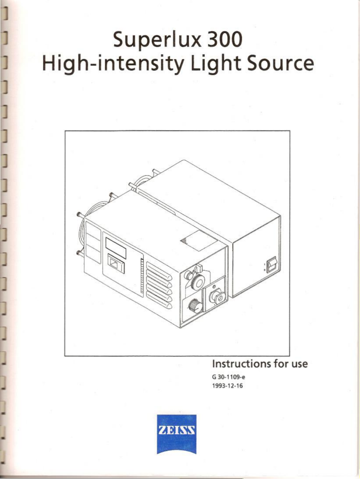
Superlux
300
High-intensity
Light
Source
Instructions
G30-1109-e
1993-12-16
for
use
Page 2
Contents
Page
Notes
Notes
Warning
Control
Lamp
Power
Xenon
Halogen
Triggering
Pre-surgery
Using
Xenon
Maintenance
Exchanging
Exchanging
Setting
Changing
Troubleshooting
on
safety
on
installation
signs
elements,
house
supply
illumination
and
and
notes...
connections
unit
.
illumination
the
camera
checklist
the
instrument
lamp
backup
the
the
the
instrument
fuses
during
procedure
.
xenon
halogen
lamp
to
..
table
usage
and
displays
an
operatio
module
lamp
the
available
Li
.
line
voltage
4
4
6
ee
............
7
9
9
n
12
13
13
18
14
14
15
15
16
16
7
/
7
18
|
es
Inetalatión
Retrofit
Control
Spare
Specifications
Important
Notes
Pre-surgery
Troubleshooting
possmamien
kts
for
stands / mounts
units
for
photography
parts
for
safety
on
safety
checklist
table
..
on
tanda y tro
Ks
and
porto
20
εμας,
198
21
21
22
Page
4
14
18
Page 3
Notes
on
safety
CAUTION:
Safety
is
only
ensured
erated
carefully
obtain
tion
Notes
Regulations
*
©
©
properly.
before
turning
further
information
or
authorized
on
installation
The
Superlux
developed
regulations.
and
and
Practice),
Its
ble
accident
The
gency
regulations
ty
in
Manufacturing,
service
international
the
instrument
are
duty
of
prevention
backup
or
when
this
Please
read
the
instrument
from
instrument
through
on.
our
service
is
this
manual
You
organiza-
representatives.
and
usage
300
high-intensity
accordance
done
in
accordance
regulations
the
operator
regulations
must
be
connected
line
supply
guidelines
which
light
source
with
the
applicable
inspection,
(Good
to
ensure
in
accordance
apply
installation
with
Manufacturing
that
are
observed
to
an
with
in
your
German
applica
op-
may
was
IEC
emer-
the
coun-
Only
use
this
instrument
specified
Itis
staff
The
user's
the
where
The
notes
special
Never
cord
The
which - if
damage
ilumination
provide
when
-
=
=
-
in
this
user's
the
duty
of
the
using
the
equipment.
operator
other
they
framed
or
Superlux
the
during
on
and/or
on
ator
must
manual
together
equipment.
are
easily
passages
and
special
care
and
attention,
pull
at
the
light
at
other
cable
300
used
improperly
to
skin
or
tissue.
closely,
copious
Superlux
skin
lissues
near
irrigation
300
prolonged
andior
in
close
with
maximum
carefully
proximity
compromised
with
the
accessories
manual.
operator
accessible
information.
is a high-intensity
maintain
proceduresiexposure
tissues
to
train
and
read
the
Superiux
with
the
user's
manuals
Keep
the
users
at
all
times.
in
this
manual
guide
cable,
connections.
-
can
Monitor
moist
of
all
is
used:
at
short
to
the
circulation
brightness
are
Read
these
at
the
light
cause
the effects
surfaces
iluminated
focal
focal
lens
settings
instruct
all
300
of
manuals
safety
with
power
source
thermal
of
the
and
areas
distances
General
©
Do
not
operate
areas.
Its
use
ics,
alcohol
e
Do
not
expose
water
©
Modifications
instruments
intensity
our
service
sons.
The
manufacturer
‘age
caused
the
instrument;
rights
to
03011000
Suprt
or
station
the
instrument
or
sprayed
used
light
technicians
by
unauthorized
such
claim
under
300
similar
and
will
1008-1216
the
instrument
in
the
presence
chemicals
instruments
to
water.
repairs
with
source
may
or
not
accept
tampering
warranty.
of
is
in
damp
water
on
this
the
Superlux
only
by
other
any
persons
will
in
explosion-risk
volatile
prohibited.
splashes,
instrument
be
liability
anesthet-
rooms.
authorized
tampering
also
Do
not
dripping
and
on
300
high-
performed
forfeit
por-
for
dam-
with
any
by
This
instrument
uct.
in
order
dor
of
the
inspect
Important
Our
high-intensity
will
check
sure
Ensure
ple,
the
ing
tighten
properly.
it
before
service
the
that
these
that
screws,
safety
function
any
is a high-grade
to
ensure
instrument,
at
least
once
turning
technician
light
following
points
of
parts
on
source
points.
are
all
mechanical
nuts,
etc.)
the
instrument
are
correctly
which
technological
perfect
our
every
instrument
on
observed
and
safe
service
install
the
which
fitted
are
technicians
12
months.
for
the
microscope
The
operator
in
future,
connections
serve
or
perform a support-
and
loose
or
proc-
working
or-
must
first
time
Superlux
to
secure.
not
300
stand.
He
must
on-
(for
exam-
guarantee
Firmly
tightened
Page 4
Lu
Lu
we we
m
E
©
Make
responds
©
Only
use
ment.
©
Only
use
ing
condition.
nt
r ing
sure
the
with
the
cables
each
the
voltage
the
power
ins
at
the
available
cord
supplied
and
plugs
mi
t
voltage
line
voltage.
with
which
are
it
selector
in
cor-
this
instru-
good
work-
nt
and
©
Bo
sure
to
instrument
Xenon
short-arc
Improper
lead
+
handling
to
damagos
Because
light
do
of
spectrum,
not
use
turn
off
the
is
not
in
use.
lamp
of
the
oF
injuries.
the
high
which
the
lamp
in
main
power
switch
Xenon
Note
luminance
is
ophthalmic
shortare
the
following
of
the
similar
to
natural
applications.
when
the
lamp
may
points
lamp
and
its
daylight,
E
Mod
id
ad
SS
SS
SS
© | Go
©
©
@
©
‧
©
Important
*
through
Make
sure
9004
working
Make
sure
clamps
secure.
and
Rerattach
which
have been
Pay
special
strument
marks)
painted
Do
Make
Always
ment
the
ample,
(triangular
labels
in
red
not
cover
sure
the
when
use
to
turn
power
the
the
checklist
the
instrument
on
and
condition.
all
securing
rings
or
close
attention
and
(see
any
power
you
are
the
it
off.
switch
NC 2 floor
elements
are
properly
any
covers,
opened
ventilation
main
or
to
warning
warning
parts
figure
1).
grids
cable
is
finished
In
of
using
power
some
cases,
the
microscope
stand.
page
14.
all
equipment
such
as
installed
and
panels
removed.
symbols
signs
with
exclamation
(screws
properly
and
or
slits.
plugged
the
instrument
switch
of
this
may
stand,
the
is
in
screws,
firmly
or
caps
on
the
in-
surfaces)
in.
instru
also
be
for
ex-
+
Never
look
the
microscope
e
Ha light
guide
receptacies,
injuries
©
Do
RISK
As
for
sion
HIGH
The
ignition
HOT
‘Some
touched.
Safety
+
The
tem
the
when
not
cover
OF
EXPLOSION:
all
pressurized
due
to
the
VOLTAGE:
lamp
is
unit.
SURFACES:
parts
of
system
instrument
as a backup
xenon
directly
guide
into
objective
is
not
installed
there
the
illumination
any
ventilation
vessels,
high
pressure
ignited
the
lamp
by
high
may
contains
light
bulb
goes
out.
the
light
source,
or a light
is a danger
within
voltage
cause
a
source,
guide.
in
one
is
on.
grids
or
there
is a tisk
the
xenon
generated
bum
halogen
ilumination
which
e.g.
into
of
the
light-
of
fire
or
bum
sits.
of
explo-
bulb,
by
the
injuries
when
sys-
can
be
used
if
CE
3011054
Super
300
1088-12-16
Page 5
Warning
CAUTION:
You
signs
must
observe
=
CAUTION
Keep
Do
pas
veto o ps
Lemon
iz
NE
-
ah
vents
bee.
ot
cover
we
‘ATTENTION
eme
nt
de
ne
vr
mr
ler
and
all
notes
warning
signs
and
notes!
WARNING:
ol
fire.
fuse
Risk
Replace
as
marked
caumow
Hot
Surfaces!
For
details,
oo chapter
"se
ot
nsrument,
p.
19
CAUTION.
ns
tray
“pay
~
caso
Cau
し
ures
Due o μα
ero”
foe]
ATTENTION
Fan
‘Assurer
par
un
EE
Fatman
explosion.
employer
g'anesihésiques
y
Ао
la
maintenance
personnel
qualifié._||
avant
us
No
pas
on
présence
Read
users
manual!
For
details,
see
chapter
“Operation
instrument,
CAUTION - Risk
||
САО
seco
‘servicing
Service
TANG
||
supply
‘hazard.
||
brasede
flammable
ofthe
p.
13
of
meee
to
personnel.
before
Do
not
ας.
quellied
Dc
-
Explosion
not
οἱ,
anesthetics.
63011064
Suprtx
300,
1008-1218
Page 6
General
The
Supertux
the
lamp
light
travels
‘endoscope
The
xenon
whose
color
temperature
less
of
light
film
tional
conversion
The
brightness
300
high-intensity
house
(1)
and
from
the
lamp
over a light
lamp
spectrum
the
brightness
in
photographic
can
guide.
of
the
is
near
of
the
setting.
fiers.
be
adjusted
light
source
the
power
supply
house
to
the
Suporlux
that
light
documentation
300
of
natural
remains
You
may
at
the
lamp
consists
unit
microscope
generates
daylight.
constant
thus
without
house.
of
(2).
The
or
light
The
regard-
use day-
addi-
The
xenon
tensity
ог
and
lamp
when
The
lamp
lamp
as a backup
lamp
ever
delay.
All
that
of
the
light-guide
lamp
house
the
halogen
from
an
the
brightness
is
located
termal
power
lamp
can
be made
making a photographic
house
also
contains a 12
ilumination
goes
out,
you
you
have
and
switch
to
"HALOGEN".
lamp
is
provided
extemal
power
adjustment
on
the
microscope
supply
unit
to
“flash”
can
continue
to
do
is
change
the
The
on
supply
element
exposure.
V,
system.
selector
electrical
the
microscope
unit.
The
for the
stand
to a higher
100 W halogen
Il
the
surgery
the
connection
(1.2)
supply
on/off
or
on
in-
xenon
without
on
the
for
stand
switch
halogen
the
ex-
CAUTION:
High
intensity
improper,
Used
1
may
causo
Seo
nstruetons
light
souce.
emitted
Burns
to
skin
fr
Use
ight
or
16946.
(30.106
Super
00.
1099-1216
Page 7
Page 8

Control
1
Lamp
1.1
Beady
This
elements,
house
lamp
lamp
lights
ignite.
1.2
Selector
Select
the
xenon
the
"XENON"
light
before
The
xenon
(1.2)
to
the
ten
seconds,
‘As
soon
as
lector
(1.2).
In
the
"HALOGEN"
gen
lamp
is
microscopic
tion
or
when
tion.
For the
change
the
light-guide
unit
(1.10).
The
on/off
brightness
scope
stand
13
connections
(figures
when
lamp
position.
you
can
lamp
lightning
the
xenon
3
and
the
xenon
by
switching
The
ignite
the
is
ignited
symbol
lamp
ready
xenon
by
and
ignites,
position, the
selected.
application
the
halogen
connection
receptacle
switch
adjustment
This
lamp
requires
xenon
lamp
fails
illumination,
of
the
(1.11)
for
the
halogen
is
located
cle
for
xenon
4)
lamp
is
the
selector
lamp
(1.1)
lamp.
tuming
the
holding
it
release
12
V,
100 W halo-
is
used
halogen
during
an
you
must
light
guide
of
Slide-in
lamp
on
the
lar
and
displays
ready
to
to
must
selector
for
up
to
the se-
when
the
illumina-
opora-
also
to
the
lamp
and
the
micro-
1.4
Hour
counter
ο.
The
hour
xenon
lamp
entire
EET
1.5
Xenon
The
scribed
1.6
Safety
1.7
Housing
The
ing
When
on,
safety
ing
1.8
Ventilation
1.9
Brightness
‘The
1.10Siiderin
Exchanging
operation.
than
500
corresponds
This
counter
each
use
should
lamp
procedure
on
always
module
page
notes
door
xenon
lamp
door
is
open.
the
door
the
xenon
reasons.
the
door.
slits
regulation
brightness
lamp
is
unit
the
counter
can
scale
The
hours.
to
of the
for
16,
cannot
is
opened
lamp
Ro-ignito
indicated
for
lamp
for
the
be
read
represents
scale
does
The
example
approx.
should
be
exchanging
is
halogen
is
65
be
xenon
lamp. A spare
avaiable.
be
ignited
when
automatically
the
xenon
xenon
in
percent.
illumination
described
operation
at
marking
500
not
hours.
checked
the
when
the
xenon
lamp
lar
on
p.
of
A.
hours
register
shown
lamp
tuned
more
here
before
lamp
is
the
hous-
lamp
off
after
16.
9
the
The
of
de-
is
for
clos-
(3041084
Suproc
00.
1903-12-16
‘1.11
Light-quide
1.128
Light
The
versions.
number
Catalog
1-13Cable
lamp
Our
1.14instrumont
The 5 pin
‘ion
receptacle
guide
light
guide
is
Only
use
90 in
the
catalog
number:
eyelets
service
sockets
{or
technician
connector
and
13
(2.9)
for
halogen
available
light
guides
number.
30
34
81-
electrical
will
pin
connectors
on
the
power
lamp
in
2.5,
3.0
which
Example:
9030.
supply
connect
of
these
plug
supply
and
3.6
m
contain
the
into
the
halogen
eyelets.
connec
unit.
CAUTION:
[Use
only
insulated
|endoscopic
light
guide * 30 34
procedures.
81-
9530
for
al
Page 9

QNo
aad
οἱ
さ の
αἲ
ο
の
Page 10

11
2
Power
21
Power
This
house.
22
Voltage
The
here.
page
23
Cover
Open
voltage
For
able
24
Power
supply
switch
switch
turns
on
indicator
which
voltage
details,
to
details
For
12.
this
cover
the
instrument
see
"Setting
ne
voltage
inlet
socket
when
/
Changing
unit
(ig.
the
power
instrument
the
“Preparations
see
you
is
set
the
5)
supply
want
to or
instrument
fuses”,
to
set
is
for
to
change
change a fuse.
to
the
page
17.
the
lamp
given
is
use”,
the
line
ave
2.5
"Switch"
Connection
and
2.6
"Camera"
Connection
connection
socket
synchronous
connection
socket
camera.
2.7
Safety notes
2.8
Ventilation
2.9
Connection
For
2.10Connection
This
technicians
sits
sockets
instrument
socket
connection
when
socket
(J
3)
for a switch
triggering
for
(J1
connectors
(J
socket
working
of a 35
socket
(J
4)
cable for
and
triggering
J2)
(1.14),
5)
only
is
the
on
for
"flash"
mm
used
mode
camera.
a
35
mm
service
by
instrument.
62011081
Supa
300
19031216
Page 11

Preparations
Our
service
and
the
paring
scribed
technician
power
supply
the
instrument
below.
for
use
will
mount
unit
(2)
for
use,
on
he
the
lamp
the
stand.
will
proceed
house
When
pre-
as
de-
(1)
12
© | Check
*
e
CAUTION:
Only
in
Example:
*
©
‧
Itis
alive
the
voltage
Note:
line
voltage
at
instrument
present.
For
age / changing
Connect
tion
Insert
(1.3).
the
Connect
let
Connect
connection
Connect
camera
the
The
voltage
given
the
place
The
details
the
socket
the
use
light
catalog
Catalog
the
socket
the
the
to
connection
duty
of
requirements
given
instrument
in
used
must
of
installation.
for
uso
fuses
may
see
"Setting
voltages”
instrument
(2.9).
light
guide
guides
number.
number:
power
footswitch
socket
(2.5).
connection
the
customer
remain
on
the
voltage
the
in
set
is
destination
the
correspond
with
also
the
(page
connector
into
which
30 34
cable
for
socket
to
satisfied.
to
the
If
not,
you
the
voltage
have
to
be
instrument
17).
(1.14)
light-guide
contain
to
triggering
cable
the
81-
9030
(2.4)
and
for
(2.6).
ensure
that
indicator.
the
factory
for
country.
line
must
changed.
for
number
The
voltage
set
the
which
to
receptacie
is
line
volt-
connec-
90
to a line
the
triggering
these
out
camera
to
the
opor-
G
301109.
Super
300.
1908-1248
Page 12

Operation
CAUTION:
Observe
Superlux
-
=
-
- — Never
the
300:
Because
lamp
and
natural
mic
applications.
Never
to
the
light
guide.
The
Superlux
source
thermal
cover
Make
sure
of
the
instrument
following
of
the
its
light
daylight,
look
directly
microscope
which
- if
damage
the
that
points
high
luminance
spectrum,
you
must
into
the
objective,
300
is a high-intensity
used
to
skin
or
ventilation
there
is
sufficient
when
which
not
light
improperly
tissue.
slots.
using
of
the
xenon
is
similar
use
it
in
ophthak
source,
endoscope,
ventilation.
-
can
0.9.
cause
the
to
in-
or
a
light
13
Xenon
Before
proximal
receptacle
source
of
the
there
the
the
e
©
©
illumination
switching
light-guide
and
surgical
is a danger
concentrated
distal
end
Switch
switch
Switch
is
ready
Turn
selector
it
for
up
lamp
ignites,
on
the
end
in
the
Superlux
the
distal
end
microscope
of
fire
light of
of
the
light
guide.
on the
(2.1).
selector
for
power
(1.2)
ignition,
to
the
(1.2)
to
ten
seconds.
release
selector
xenon
is
or
the
to
the
lamp,
inserted
300
high-intensity
in
the
illumination
or
endoscope.
of
burn
injuries
xenon
lamp,
at
the
stand
"XENON".
ready
lamp
lightning
As
soon
(1.2)
make
sure
in
the
light-guide
component
If it
caused
especially
and
at
When
the
(1.1) lights.
symbol
as
the
and
the
light
is
not,
by
at
power
lamp
hold
xenon
Halogen
Note:
if
the
only
the
halogen
mediately
e
©
e
e
page
switch
Tum
selector
İnsert
the
guide
receptacle
Note:
The
from
the
Turn
on
adjust
the
Changing
17.
Note:
It
takes
a bit
longer
to
ignite
the
xenon
lamp
when
itis
warm
illumination
xenon
lamp
fails
during
illumination
to
the
(1.2)
to
proximal
(1.11).
electrical
microscope
the
halogen
brightness.
the
halogen
can
be
halogen
illumination.
"HALOGEN".
light-guido
supply
for
stand.
illumination
lamp
an
operation,
used,
you
end
into
the
the
halogen
at
the
stand
is
described
or
may
im-
light-
lamp
is
and
on
if
©
Using
brightness
xenon
lamp
gical
procedure.
sively.
53011080
Super
adjustment
to
the
brightness
Do
not
300
1993.1218
knob
(1.9)
adjust
desired
illuminate
for
the
tissue
the
the
sur-
exces-
Page 13

Triggering
In
order
the
xenon
must
be
era”,
over a camera
The
camera
ners:
*
by
floor
©
using
©
using
You
must
shortest
the
camera
to
automatically
lamp
when
connected
is
triggered
pressing a button
stand
or
ceiling
the
hand
the
double
press
the
flash
interval
generate a "flash"
making a photograph,
to
connection
control
or
switch
cable.
in
in
mount.
foot
control
footswitch.
once
is 2 seconds.
one
of
the
handles
unit
for
socket
each
of
the
(2.6),
the
following
of
exposure.
light
from
camera
"cam-
man-
the
NC
The
2
Pre-surgery
Check
through
tion
(without
©
All
cables
Xenon
lamp
e
Chock
Check
endoscope.
Check
Have a spare
Halogen
‧
Turn
Check
checklist
the
following
the
patient)
are
connected.
the
ignition
the
illuminated
the
hour
counter.
lamp
lamp,
it
on
and
check
the
illuminated
points
before
and
brightness
field
of
avaiable,
the
brightness
field
of
the
every
opera-
adjustment.
the
microscope
adjustment.
microscope.
or
Notes:
The
gerdiess
Photographic
When
footswitch.
maximum
exposure,
The
light
whose
color
using
xenon
lamp
spectrum
temperature
of
the
brightness
documentation.
the
halogen
The
first
stage
brightness
and
of
the
Superlux
is
near
that
of
the
light
setting.
lamp,
trigger
switches
the
second
300
generates
of
natural
remains
Use
daylight
the
the
halogen
stage
daylight.
constant
camera
triggers
re-
film
for
at
the
light
to
the
Note:
Check
begins.
both
illumination
CAUTION:
I
one
of
the
functions
erate
using
this
fault
(see
the
trouble-shooting
erwise contact
На
function
emergency
rect
the
page
18.
our
fails
instructions
fault
using
systems
prove
instrument.
service
during
on
the
before
to
be
faulty,
if
possible,
table,
department.
an
operation,
page
15.
If
trouble-shooting
the
operation
do
not
op-
correct
page
observe
possible,
the
18),
oth-
the
cor-
table on
(620-100.
Suporta00
1908-12-16
Page 14

15
Using
©
e
*
the
instrument
Switch
(2.1).
equipped
switch
the
on
the
Select
(1.2)
Adjust
xenon
use
illumination
Caution:
The
which - if
age
mination
vide
the
+
-
-
>
the
th
with à line
(2.1)
stand
then
and
off
NC 2 floor
the
xenon
the
brightness
lamp
the
minimum
Superlux
used
to
skin
or
closely,
copious
Superlux
during
on
and/or
on
at
irrigation
300
prolonged
skin
andior
in
close
tissues
or
near
during
Superlux
Superlux
may
together
stand.
brightness
300
improperty
tissue.
is
with
maximum
300
300
voltage
remain
automatically
with
the
lamp
and
at
the
adjustment
brightness
is a highintensity
-
can
Monitor
maintain
used:
tissues
proximity
compromised
moist
of
all
proceduresiexposure
at
brightness
an
operation
on
at
the
power
is
used
with a stand
power
outlet,
on.
The
power
turns
the
Superlux
stand.
An
ignite
it
using
surgical
required
cause
the
iluminated
short
to
the
field
(1.9).
for
light
thermal
effects
surfaces
areas
focal
focal
lens
circulation
settings
switch
power
switch
of
300
example
using
adequate
of
the
and
distances
is
selector
the
Always
source
dam-
ilu-
pro-
when
Xenon
©
‧
©
©
‘©
A
even
after
again
lamp
Switch
tor
Change
halogen
Switch
stand
brightness.
After
module
"Exchanging
Rercomnect
receptacle
xenon
to
(1.2),
the
light-guide
on
or
extemal
it
has
and
and
lamp
which
though
it
after a short
it
has
cooled
backup
the
connection
the
cooled
switch
the
the
may
period
procedure
halogen
halogen
power
xenon
light
rerignite
has
be
down.
illumination
of
receptacle
lamp
supply
down,
exchange
back
to
lamp
guide
to
the
xenon
failed
must
possible
The
of
time.
using
the
light
guide
(1.11).
at
the
microscope
unit
and
adjust
the
xenon
the
xenon
module”,
the
lamp.
page
xenon
light
lamp.
not
be
used
to
re-ignito
lamp
will
the
normally
selec
to
the
the
lamp
See
16,
guido
again
lamp
fail
Caution:
To
ensure
equipment,
9530
220-1100
proper
use
for
all
endoscopic
Süperr
00 10031216
insulation
insulated
of
the
light
guide * 30 34
procedures
patient
from
the
81-
Page 15

Maintenance
Exchanging
CAUTION:
-
Hot
Never
+
Risk
The
When
kPa,
lamp
Always
pletely
ue
the
surfaces:
touch
the
of
explosion:
xenon
and
is
wall
(approx.
lamp
it
is
cold,
it
rises
on.
until
5
the
min.)
xenon
slide
lamp
in
unit
is a high-pressure
the
pressure
to
approx.
lamp
before
module
when
it
is
hot
is
approx.
3000
kPa
when
has
cooled
exchanging
down
the
vessel.
1400
the
com
mod-
‘CAUTION:
High
intensity
H
used
may
cause
Soe
Instructions
17
ight
improper,
burns
[
souce.
emited
to
skin
for
or
Use.
light
issue.
16
*
Switch
©
Side
shown
*
Uso
grips
ule
out
©
Install
A
xenon
lamp
even
though
after
it
has
again
after a short
selector
ihe
in
ol
tho
(1.2)
housing
the
figure
(1.15)
to
the
lamp
now
xenon
which
has
it
may
be
cooled
down.
period
to
"off".
door
lock
(1.7)
and
open
the
door.
pull
the
entire
housing.
lamp
in
reverse
failed
must
not
possible
of
to
The
lamp
time.
reignite
in
the
direction
xenon
lamp
order.
be
used
the
will
normally
mod-
again
lamp
fail
1.15
03011000
Superiø300
1983-1215
Page 16

17
Exchanging
CAUTION:
When
you
it
is
gone
vent
burns.
+.
Pull
©
Take
pull
pins
‧
Install
-
hole
-
the
lamp
©
Attach
pins
(1.18).
©
Rovinsort
Note:
Only
Cat.
no,
38
the
exchange
out,
wear
the
lamp
unit
the
halogen
the
ceramic
(1.18).
the
new
halogen
The centering
for
it
in
the
lamp
Do
not
touch
reflector.
the
ceramic
the
lamp
12V,
100W
00
79-
9040.
halogen
the
heat-protection
(1.10)
lamp
mount
tongue
the
unit into
lamp
halogen
out
lamp.
unit
lamp
mount
halogen
lamp
of
the
out
of
the
(1.16)
off
Note
(1.17)
bulb
(1.16)
the
instrument.
lamps
(igure
shortly
gloves
instrument.
lamp
of
the
the
following:
must
fit
or
the
to
the
may
10)
after
to
pre-
unit
and
contact
into
the
interior
of
contact
be used.
10
1
1.10
Setting
voltage / Changing
©
e
©
©
|
ο
the
instrument
Open
cover
(2.3)
lector
unit
(2.11).
Tum
the
selector
ure)
required
Pull
out
fuses
ing
plate
Re-insert
er
(2.3).
ο...
and
the
fuse
(2.14)
in
(for
fuse
the
to
the
fuses
at
part
unit
re-insert
holders
accordance
ratings,
fuse
(figure
(2.12)
and
(2.11)
to
the
i
(2.13)
and
with
labeling
see
page
holders and
available
11)
remove
voltage
exchange
22).
close
the
(seo
on
the
the
line
se-
fig-
the
rat-
cov-
213 214
23
Page 17

18
Troubleshooting
If
there
is a malfunction,
Malfunction
No
function
Xenon
functioning:
Lamp
at
all:
illumination
Lamp
goes
out
(xenon
table
use
not
does
not
during
operation:
No
lamp
has
ignited)
this
trouble-shooting
Possible
Power
power
Main
Defective
power
Power
Failure
ignite:
light:
Switch
position
Door
Defective
Defective
Door
Power
Covered
Thermal
Defective
Defective
Light
receptacle,
Defective
table
cause
cord
not
supply
power
switch
fuse
supply
failure.
of
stand
(1.2)
on
HALOGEN.
of
lamp
lamp.
power
of
lamp
cable
not
ventilation
circuit
xenon
power
guide
not
light
to
find
the
cause.
properly
unit
in
stand
unit
electronics.
lamp
housing
supply.
housing
properly
breakers
lamp.
supply.
inserted
guide.
connected
or
stand.
(2.1)
not
or
(2).
housing
open
open.
plugged
slots.
activated
or
in
pressed,
in
wrong
Remedy
at
Connect
Press main
must
Change
Contact
Contact
Switch
(Close
Insert
Contact
Close
in. | Connect
Reignite
Uncover
Switch
guide
‘on
brightness.
light
the
lamp
‘Switch
or
‘Switch
Plug
component
endoscope
guide
Supertux
‘Change
power
switch,
come
on.
power
in-house
service
to
XENON
door
and
new
lamp
service
door
and
power
xenon
slots.
to
halogen
into
halogen
halogen
xenon
insert
lamp
After a few
guide
can
lamp
re-ignited.
to
halogen
new xenon
to
halogen
light
guide
on
and
receptacle
300.
light
guide.
plug.
Green
pilo
light
fuse.
electrician.
technician.
and
re-ignite.
reignite
module.
technician.
re-ignite
plug.
lamp.
be
unit
into
microscope
into
on
Xenon
lamp.
Xenon
lamp.
lamp
and
plug
lamp
unit;
switch
at
stand
and
adjust
minutes,
plugged
and
lamp
lamp
lamp.
ilumination
xenon
the
back
into
the
xenon
module.
or
lamp
light-
İİ
nn
am
Tight
011000
Supe
300
1068-1246
Page 18

Malfunction
Light
too
low:
Light
is
flickering:
Possible
Shutter
Tight
90.
Detective
Defective
Defective
Defective
Defective
cause
in
lamp
guide
not
light
lamp.
power
lamp.
power
housing
inserted
guide.
supply.
supply.
closed.
as
far
as
it
Remedy
Open
shutter
illumination.
will
Insert
both
they
will
go.
Change
Change
Contact
‘Switch
I
Contact
‘Switch
Contact
light
lamp
service
to
necessary,
service
to
service
using
(1.9),
ends
of
light
guide.
unit.
technician:
halogen
halogen
lamp.
replace
lamp
technician.
lamp.
technician.
avoid
excess
guide
as
unit.
19
far
as
Halogen
functioning:
illumination
Lamp
Lamp
goes
out
not
does
not
come
during
operation:
(lamp
operative)
Light
on:
No
light:
too
low
Main
power
switch
on
‘Switch
tion
in
housing.
Light
ceptacle,
in
Light
go.
Defective
Detective
Defective
(1.2)
on
XENON.
Brightness
position
Lamp
Defective
Defective
Defective
Incorrect
Defective
Brightness
position
adjustment
0.
unit
does
lamp.
power
lamp.
connection
power
guide
not
adjustment
0.
guide
not
light
guide.
lamp.
power
stand
lamp
housing
knob
not
fit
ightly
supply.
of
power
supply.
inserted
inserted
supply.
or
knob
as
OFF.
in
posi
on
stand
in
lamp | Push
cable.
in
wrong
on
stand Use
far
as wil | insert
Switch
Switch
Use
required
Change
Contact
Change
Connect
‘Contact
re-
Insert
halogen
required.
they
Change
Change
Contact
on
to
halogen
knob
to
adjust
in
lamp
lamp.
service
lamp.
power
service
light
guide
lamp
knob
to
adjust
bolh
ends
will
go
light
guide.
lamp
service
lamp.
to
brightness
unit
as
far
as
it
will
technician
cable.
technician,
in
receptacle
unit.
to
brightness
of
ight
guide
as
unit
technician,
go,
of
far
as
63011026
Super
300
1068-1216
Page 19

Installation
possibilities
Superlux
Catalog
Stands / mounts
Foor
stand
re-equipped
300
number
NC
1
for
uso
30 49
on
stands / Retrofit
53-0000
with
OPM-CS
kits
and
parts
Retrofit
Retrofit
kits for
kit
stands / mounts
Catalog number:
30 49
20
53-9054
Floor
stand
not
re-equipped
Ceiling
ro-equipped
Ceiling
not
Floor
Ceiling
Floor
Ceiling
mount
mount
re-equipped
stand
mount
stand
mount
NC
1
for
use
NC
1
for
use
with
NC
1
for
use
NC
2
NC
2
$2 / $3 /
$2 / $3 / $4
with
OPMLCS
with
S4
OPM-CS
OPMLCS
Retrofit
and
Retrofit
Retrofit
Retrofi
and
Retrofit
A
Retrofit
Retrofit
Retrofit
kit
kit
kit
kit
kit
retrofit
kt
is
kit
kit
kit
not
Catalog number:
Catalog number:
Catalog number:
Catalog
Catalog number:
Catalog
Catalog
Catalog
number:
required,
number:
number:
number:
30 49
30 49
30 49
30 49
30
49
30 49
30
49
30 49
53-9054
53-
9059
53-9055
53-9055
53-
9059
53-9057
53-9050
53-9052
ο...
Page 20

21
Superlux
Catalog
300
number
30 49
53-0000
Stands / mounts
[>|
—|
(—
|
(Floor
[>|
|]
>|
Floor
stand
with
surgical
ceiing
with
surgical
Poor
stand
without
Colling
without
stand
with
surgical
Ceiling
without
Floor
stand
Ceiling
NC
1
microscope
mount NC
surgical
mount
surgical
mount
surgical
mount
1
microscope
NC
1
microscope
NG
1
microscope
NC
2
microscope
NC
2
microscope
$2/
$3 / 84
$2 / $3 / 54
OPMI
CS
OPMI
CS
OPM
OPMI
OPMI
CS
OPM
Control
Footswitch
control
Footswitch
control
Footswitch
CS | control
Footswitch
CS
CS
control
The
mount.
Optional:
Footswitch
Ft.
|and:
control
Contax
Footswitch
control
Footswitch
control
units
cable,
cable,
cable,
cable, 4 m,
hand
triggering
control
unit 8 functions
cable,
800
RTS 167
cable, 4 m,
cable, 4 m,
4
m,
4
m,
4
m,
for
for
for
for
for
mm,
MT
for
for
photography
Catalog
Contax
Contax
Contax
Contax
element
Contax
Contax
RTS
RTS
RTS
RTS
is
integrated
for
RTS
RTS
39 35
9049
39 35
3049
39 35
80
49
39 35
30
49
in
stand
39 35
30 49
30
97
39
35
02-0000
3049
53-0056
39
35
02-0000
3048
number
02-0000
53-9056
02-0000
53-9056
02-0000
53-0056
02-0000
53-9056
/
02-0000
81-0000
34-0000
53-9056
Spare
parts
ra
NC
1/NG 2 floor
mounts
3.0 m S
$2,
$3,
2.5 m 8
$2,
$3,
3.0 m insulated
for
endoscopy
30-106.
Supine
....
light
guido
34
celling
light
guide
$4
floor
light
300,
1009-1218
Catalog
stands / ceiling
30
34
for
mounts...
for
stands
......
guide
............
30
34
30 34
9084
number
81-9036
81-8090
81-9025
81-9530
Spee
A
κο
T63A
SLO
foro
κος
.
BLO
taser
io
pom
ιν
500
emp.
Catalog
number
0148107
개
0146811
50108
Page 21

oe
Specifications
Electrical
Line
voltage:
Frequency:
Power
consumption:
Fuse
ratings
of
ine
power
fuses:
118/230
Class
50...60
500
for
Catalog
for
Catalog
V~ + 15%
|,
Туре
Hz
VA
115
V:
number
230
V: T 3,15 A SLO BLO
number
В
T6,3 A SLO
0127.
BLO
0146.811
22
Operative
Flash
Lamp
Maximum
‘surgical
1=
200
Dimensions
data
interval
output
power
illumination
field
with
mm
objective:
and
Weight:
Dimensions
Wumination
Mumination
300 W xenon
(HxWxD)
system
via
lamp
with near
of
xenon
lamp:
in
weights
fiber-optics
ight-guide
daylight
‘Shortest
280
W
850
to
1000
Lamp
house
Xenon
Power
Lamp
Power
spectrum
lamp
supply
house
supply
cables
(daylight
flash
interval:
kLx
without
module:
unit:
150x150x300
unit
fm
2
lamp
0.9
8.9
kg
150x150x300
can
be
s
module:
kg
mm
used)
4.7
mm
kg
12
V,
100 W halogen
Subject
(630-1004
to
change.
Supra
200
lamp
as
19851216
backup
light
source.
 Loading...