

Page 1

Operating Manual
February 2013
ZEN 2012 (black edition)
Lightsheet Z.1
Page 2

Carl Zeiss Copyright Lightsheet Z.1
Knowledge of this manual is required for the operation of the instrument. Would you therefore please
make yourself familiar with the contents of this manual and pay special attention to hints concerning the
safe operation of the instrument.
The specifications are subject to change; the manual is not covered by an update service.
© Unless expressly authorized, forwarding and duplication of this document, and the utilization and
communication of its contents are not permitted. Violations will entail an obligation to pay
compensation.
All rights reserved in the event of granting of patents or registration of a utility model.
Issued by Carl Zeiss Microscopy GmbH
Carl-Zeiss-Promenade 10
07745 Jena, Germany
microscopy@zeiss.com
www.zeiss.com/microscopy
II 000000-1790-528 02/2013
Page 3

INTRODUCTION
Lightsheet Z.1 Carl Zeiss
Contents of this Manual
Chapter 1
Chapter 2
Chapter 3
Chapter 4
Annex
Hardware
Sample Preparation
Quick Guide
Software Operation
Lightsheet Z.1 - Overview
02/2013 000000-1790-528 III
Page 4

Page 5

CHAPTER 1 - HARDWARE Lightsheet Z.1 Content Carl Zeiss
CHAPTER 1 HARDWARE
CONTENT
Page
1 MAINTENANCE AND CLEANING ......................................................................... 3
1.1 Maintenance of the Liquid Cooling System ................................................................. 5
2 ERGODRIVE OPERATING PANEL ......................................................................... 6
3 USER INTERFACES ............................................................................................... 9
3.1 Installation and Deinstallation of the Detection Modules ........................................ 10
3.2 Adjustment – Detector Recognition ........................................................................... 15
3.2.1 Adjustment – Automatic Detector Alignment .................................................................. 15
3.2.2 Adjustment – Manual Detector Alignment ...................................................................... 17
3.2.3 Adjust the Grating Focus for the Automatic or Manual Detector Alignment Tool .............. 19
3.2.4 Cable Connections for the Detection Module "PCO.Edge" .............................................. 22
3.2.5 Cable Connections for the Detection Module "Standard" ............................................... 23
3.3 Assembly of the Sample Chamber ............................................................................. 24
3.3.1 Assembly of the Sample Chamber Windows ................................................................... 24
3.3.2 Assembly of the Sample Chamber Body and the Sample Chamber Dove Tail Slide ............ 27
3.3.3 Insertion of the Drain Connector, Luer-Lock Connectors and Blind Plugs .......................... 29
3.3.4 Insertion of Accessories for Incubation ............................................................................ 30
3.4 Removing and Inserting the Sample Chamber .......................................................... 31
3.5 Assembly of the Sample Holder ................................................................................. 32
3.5.1 Assembly of the Sample Holder for Capillary ................................................................... 32
3.5.2 Assembly of Sample Holder for Syringes .......................................................................... 34
3.6 Inserting and Removing the Sample Holder .............................................................. 35
3.7 Installation of the Incubation Modules ...................................................................... 37
3.7.1 Heating Components ..................................................................................................... 37
3.7.2 CO
3.7.3 Heating Device Humidity S1 ............................................................................................ 41
3.7.4 Registration of the incubation modules ........................................................................... 41
3.8 Switch Incubation ON and OFF ................................................................................... 43
02/2013 000000-1790-528 1
-Module Lightsheet Z.1 ............................................................................................. 39
2
Page 6

CHAPTER 1 - HARDWARE
Carl Zeiss Content Lightsheet Z.1
3.9 Illumination and Detection Optics ............................................................................. 43
3.9.1 Removing and Inserting the Illumination Optics Unit ....................................................... 45
3.9.2 Removing and Inserting the Detection Optics Unit........................................................... 46
3.10 Removing and Inserting the Reflector Turret for Emission Selection ...................... 47
3.11 Removing and Inserting the Reflector Turret for Laser Blocking Filter .................... 49
4 INDEX ................................................................................................................. 52
2 000000-1790-528 02/2013
Page 7

CHAPTER 1 - HARDWARE
Lightsheet Z.1 Maintenance and Cleaning Carl Zeiss
1 Maintenance and Cleaning
The maintenance to be carried out by the customer is limited to cleaning the painted surfaces, replacing
glass windows and rubber seals on the sample chamber, cleaning and disinfecting the system cavity and
sample chamber, temperature sensors and detection optics unit, replenishment of coolants for the
incubation device and liquid cooling of the detection module as necessary, as well as the replacement of
CO
sterile filters for the incubation device.
2
a) To clean painted surfaces proceed as follows:
• Switch the device off completely and pull the mains plug.
• Make sure that no cleaning fluid is allowed to enter the system.
• Wipe the painted surfaces with a clean cloth moistened with water to which a small amount of
cleaning agent has been added. Do not use a solvent. Dry off with a lint-free cloth.
b) To clean and disinfect the system cavity proceed as follows:
• Switch the device off completely and pull the mains plug.
• Make sure that no cleaning fluid is allowed to enter the system.
• Take care not to touch the front lens of the illumination and detection optics units. Remove these
optics as necessary.
• Remove the sample chamber for cleaning.
• Cleaning the system cavity:
Wipe the inner surfaces of the system cavity with a clean cloth moistened with water to which a
small amount of cleaning agent has been added. Do not use a solvent. Dry off with a lint-free
cloth.
• Disinfecting the system cavity:
Carefully wipe the inner surfaces of the sample chamber with a lint-free cloth soaked in 70
ethanol or 70
% isopropyl. Allow the solution to react for a few seconds. Repeat the procedure
%
once or twice as necessary. Carefully wipe off the inner surfaces with a lint-free cloth soaked in
distilled water.
02/2013 000000-1790-528 3
Page 8

CHAPTER 1 - HARDWARE
Carl Zeiss Maintenance and Cleaning Lightsheet Z.1
c) To clean and disinfect the sample chamber proceed as follows:
• Remove the sample chamber and dismantle it into individual parts. Different procedures are required
for cleaning and disinfecting the various parts of the sample chamber.
− The cover glasses must be properly disposed of in the glass waste.
− The steel parts of the chamber must be cleaned and disinfected as follows:
Rinse the parts with distilled water.
Lay the parts in an ultrasonic bath containing distilled water to which a few drops of detergent
have been added.
Then rinse the steel parts thoroughly with distilled water until all detergent residue has been
removed.
The parts may be laid in a disinfecting bath of 70
% ethanol (> 1 hour) and then thoroughly
rinsed with distilled water.
The steel parts of the sample chamber may also be autoclaved as necessary.
− Sealing rings, hose connectors and blank plugs must be cleaned and disinfected as follows:
These parts may not be autoclaved.
First of all lay these parts in distilled water and then in a 70 % ethanol solution for max. one
hour. Rinse them thoroughly with distilled water.
d) To clean and disinfect the temperature sensor proceed as follows:
• Remove the temperature sensor from the sample chamber and loosen the connections to the main
system module Lightsheet Z.1.
• Once removed, thoroughly rinse the temperature sensor with distilled water and then suspend it for
one hour in a 70
% ethanol solution. Make sure that the contact plug remains dry. Complete the
cleaning process by rinsing thoroughly with distilled water.
4 000000-1790-528 02/2013
Page 9

CHAPTER 1 - HARDWARE
Lightsheet Z.1 Maintenance and Cleaning Carl Zeiss
e) To clean and disinfect the detection optics unit proceed as follows:
• Make sure that no cleaning fluid is allowed to enter the system.
• To avoid scratches, do not wipe the front lens of the optics with dry lens paper and lens cloths.
• Remove these optics from the system cavity as necessary.
• Clean the front lens of optical elements according to general recommendations (see "The clean
microscope" www.zeiss.com/microscopy) using an optical cleaning solution (Carl Zeiss optical cleaning
solution: 85
% n - hexan, 15 % isopropanol. This solution is not sold by Carl Zeiss Microscopy GmbH)
and a suitable lens cleaning paper or high purity cotton wool.
• In addition to the cleaning procedure described above, for special sterility requirements the front lens
area of the detection modules can be cleaned several times with a lint-free lens cloth or lens paper
soaked in 100
% ethanol. Here again, observe the general notes on cleaning the optics
("The clean microscope").
1.1 Maintenance of the Liquid Cooling System
If detection modules in your Lightsheet Z.1 are connected to a liquid cooling system, consider that the pH
value of the cooling liquid changes over time.
To prevent corrosion in the cooler of the detection module, the pH value of the cooling liquid must be
checked at least once a year and the liquid replaced as necessary. Observe the directions of the cooling
system manufacturer in the supplied operating manual.
If you have signed a service agreement with Carl Zeiss, our service staff will perform the check as part of
the maintenance procedure.
The safety data sheet for the cooling liquid should also be observed.
02/2013 000000-1790-528 5
Page 10
CHAPTER 1 - HARDWARE
Carl Zeiss ErgoDrive Operating Panel Lightsheet Z.1
2 ErgoDrive Operating Panel
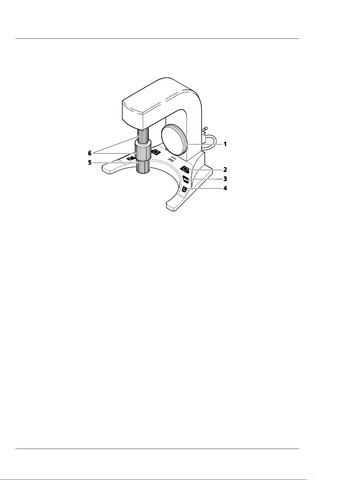
1 Z-axis control
2 Rotation button (switches 6 to rotation drive)
3 Mode button (fine / coarse)
4 Axis button (switches 6 to y-axis drive)
5 X-axis control
6 Y-axis / Rotation control
Fig. 1 ErgoDrive operating panel
6 000000-1790-528 02/2013
Page 11
CHAPTER 1 - HARDWARE
Lightsheet Z.1 ErgoDrive Operating Panel Carl Zeiss
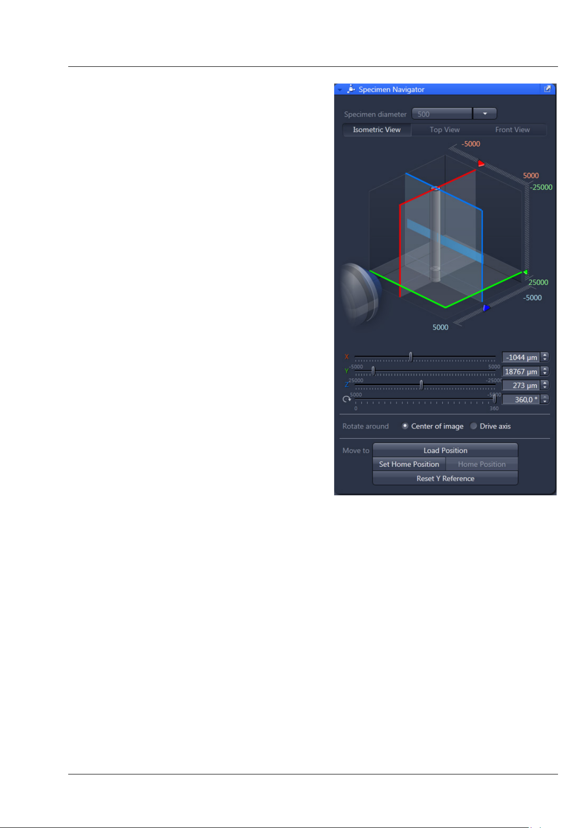
With the ErgoDrive operating panel the movement
of the sample holder and therefore the sample can
be controlled. It is the manual equivalent of sliders
in the Specimen Navigator tool in the ZEN
software (Fig. 2), with which the movement of the
specimen can be controlled as well.
The function to rotate around the center of the
image, Rotate around Center of image (Fig. 2) is
only available through the software interface. Even
if chosen there, the rotation controlled by the
ErgoDrive operating panel will always rotate
around the axis of the motor drive.
The steering elements are two vertical rotary
controls for the x, y and rotation movement.
The large rotary wheel controls the z movement
(Fig. 1).
Fig. 2 ZEN software, Specimen Navigator
tool window
02/2013 000000-1790-528 7
Page 12

CHAPTER 1 - HARDWARE
Carl Zeiss ErgoDrive Operating Panel Lightsheet Z.1
The following control elements are part of the ErgoDrive operation panel:
Buttons:
The Mode button (Fig. 1/3) changes the speed of the drive from coarse to fine and back.
The Rotation button (Fig. 1/2) changes the upper rotary control to move the rotation drive (Fig. 1/6).
The Axis button (Fig. 1/4) changes the upper rotary control to move the y drive (Fig. 1/6).
Rotation control:
Upper rotary control (Fig. 1/6), after pressing the Rotation button (Fig. 1/2):
Clockwise: clockwise rotation of the sample; the angle is reduced in the software interface
Counter-clockwise: counter-clockwise rotation of the sample, the angle is increased in the
software interface
Y axis control:
Upper rotary control (Fig. 1/6), after pressing Axis button (Fig. 1/4):
Clockwise: upward movement of the sample
Counter-clockwise: downward movement of the sample
X axis control:
Lower rotary control (Fig. 1/5):
Clockwise: right movement of the sample
Counter-clockwise: left movement of the sample
Z axis control:
Large rotary wheel (Fig. 1/1):
Clockwise: sample movement towards the detection optic
Counter-clockwise: sample movement away from the detection optic
8 000000-1790-528 02/2013
Page 13

CHAPTER 1 - HARDWARE
nd lower system cavity doors and the upper
system door are equipped with a safety interlock system to guarantee laser safety. These
be manipulated. Other interfaces not described here are reserved for
ervice personnel. The following devices
Lightsheet Z.1 User Interfaces Carl Zeiss
3 User Interfaces
The ports of the detection modules, upper a
locking devices must not
service and may only be used by authorized Carl Zeiss s
may be mounted and dismounted by, or are accessible to, the user:
− Detection modules
− Sample chamber
− Sample Holder
− Incubation components
− Illumination optics
− Detection optics
− Reflector turret.
Customized Sample Chamber
The sample chamber delivered with the Lightsheet Z.1 can be used with a multitude of media (e.g. PBS,
cell culture medium, artificial sea water) and is carefully designed to produce optimal results with the
Lightsheet Z.1 system. However, if applications demand changes to the original sample chamber, Carl
Zeiss Microscopy GmbH provides the CAD files and the corresponding technical drawing of our sample
chamber for your convenience, in accordance with the following disclaimer:
Carl Zeiss Microscopy GmbH (hereinafter “we”) hereby informs you that we will warrant the specified and
agreed performance of the Lightsheet Z.1 system only if sample chambers are applied and used that
either are delivered or explicitly approved by us.
The sample chamber design has been optimized to ensure the most established applications of Light
Sheet Fluorescence Microscopy. Exceptional applications may require a slightly modified sample chamber
design. In order to enable customized modifications of the existing sample chamber we also provide the
corresponding CAD file and a technical drawing. We explicitly advise you that already minor deviations of
the dimensions and tolerances specified in these documents will cause a significant loss of image quality
and can potentially result in a liquid leakage. Therefore, you will not hold us or one of our affiliates liable
for any damages caused by the employment of self-built or third-party-built sample chambers, the use of
such self-built or third-party-built sample chambers will be solely on your own risk. Furthermore we want
to inform you, that we will not render any assistance relating to the production and application of such
self-built or third-party-built sample chambers.
02/2013 000000-1790-528 9
Page 14

CHAPTER 1 - HARDWARE
o cool the
Carl Zeiss User Interfaces Lightsheet Z.1
3.1 Installation and Deinstallation of the Detection Modules
A cooling liquid defined as a hazardous substance is used in the Lightsheet Z.1 t
detection modules (depending on configuration). The supplied safety data sheet with notes on
hazards and safety measures must be observed when handling the cooling liquid.
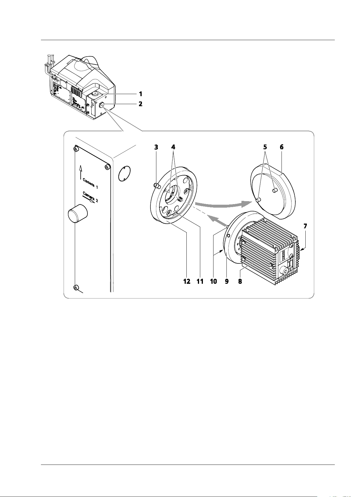
The ports of the detection modules, reflection (Cam1) (Fig. 3/1) and transmission (Cam2) (Fig. 3/2), on
the main system module Lightsheet Z.1 are equipped with a hardware interlock device. The contact rings
(Fig. 3/9) are connected to the detection modules (Fig. 3/8) and adjusted in the factory. When handling
the detection modules, ensure that neither tilting nor rotation forces are exerted on this connection to
avoid misalignment. The detection module should be gripped as close as possible to the contact ring.
A rotation guard plate (Fig. 3/7) is mounted on the contact ring of each detection module. When
mounting on both ports this must point toward the front side of the Lightsheet Z.1. It prevents rotation
of the detection module and carries the laser protection notice.
Never remove the rotation guard plates of the detection module adapters. Do not modify or
manipulate the detection module adapters.
The lock is functioning when the sensors (Fig. 3/4) of the sensor disk (Fig. 3/11) are pressed down by the
pins of the contact ring (Fig. 3/10 or 5 for blind cap). If this is not the case, e.g. the space between the
two devices is too large, the laser is blocked and the system cannot be used.
If the system does not function after a detection module has been attached to or removed from a
port with a safety interlock, check the connection of the contact ring on the respective detection
module or blind cap (Fig. 3/9 or 6) to the sensor ring.
10 000000-1790-528 02/2013
Page 15
CHAPTER 1 - HARDWARE
Lightsheet Z.1 User Interfaces Carl Zeiss
1 Detector port 1 (reflection, Cam1)
2 Detector port 2 (transmission, Cam2)
3 Securing screw
4 Sensors (2×) in sensor ring
5 Contact pins (2×) on blind cap
6 Blind cap
7 Rotation guard plate with laser protection notice
8 Detection module (varies)
9 Contact ring of the detection module
10 Contact pins (2×) on contact ring
11 Sensor disk
12 Sensor ring
Fig. 3 Mounting and dismounting the detection modules
02/2013 000000-1790-528 11
Page 16

CHAPTER 1 - HARDWARE
Carl Zeiss User Interfaces Lightsheet Z.1
The exchange of the detection modules on your Lightsheet Z.1 can be divided into two parts. One deals
with the actual mounting and dismounting of the detection modules and their connections to the
system. The second part deals with the registration and alignment of the detection module using specific
software tools.
The Lightsheet Z.1 must be completely turned off before changing detection modules.
No sample, capillary or similar object must be in the beam path while the alignment and calibration
tasks are performed.
1) Dismounting and Mounting of Detection Modules
− Disconnect all cables from the detection module.
− The connection of the liquid cooling can stay in place, but the power plug for the liquid cooling
unit must be pulled when the detection module is not in use.
− Now disconnect all cables from the Lightsheet Z.1 system and the PC for system control. Even if the
detection modules are regularly switched no cable should remain on the system.
− Hold the detection module firmly in one hand.
− Loosen the securing screw with an Allen wrench (Fig. 3/3) on the sensor ring (Fig. 3/12) of the
detector port (Fig. 3/1 and 2).
− Carefully pull away the detection module (Fig. 3/8) with contact ring (Fig. 3/9) using a slight tilting
motion if necessary.
− Cover the detector port (Fig. 3/1 and 2) on the main system module Lightsheet Z.1 and on the
detection module with the caps provided (Fig. 3/6).
− For mounting the new detection module, proceed in the reverse order. Tighten the securing screw
(Fig. 3/3) on the sensor ring (Fig. 3/12) of the detector port (Fig. 3/1 and 2) without applying force.
− With the detection module "PCO.Edge," note that part of the optics projects beyond the contact
ring. To protect it from damage and fingerprints, first push the optics into the port and then
connect the contact ring to the sensor ring.
− Connect all necessary cables to the detection module, the Lightsheet Z.1 and the PC for system
control (see section 3.2.4 Cable Connections for the Detection Module "PCO.Edge" and
3.2.5, Cable Connections for the Detection Module "Standard").
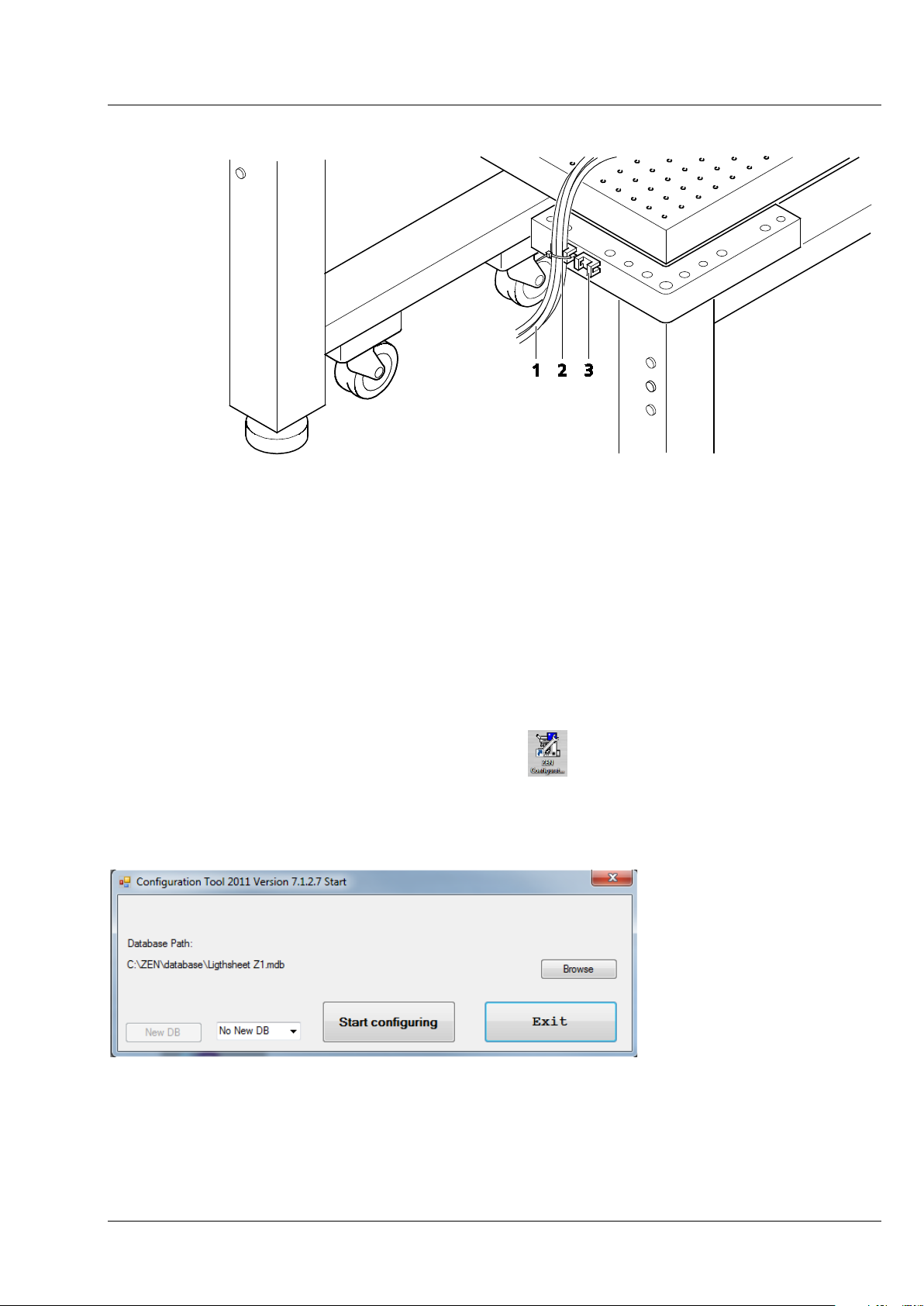
− Use the cable holder (Fig. 3/3) on the system table to connect the cables (Fig. 3/1) of the detection
modules without tension.
12 000000-1790-528 02/2013
Page 17
CHAPTER 1 - HARDWARE
Fig.
Lightsheet Z.1 User Interfaces Carl Zeiss
1 Cable (e. g. of the detection modules)
2 Cable tie
3 Cable holder on system table
Fig. 4 Cable strain relief
− Turn on the system (see CHAPTER 4, SYSTEM OPERATION).
2) Registration and Alignment of the detection modules
− After the Lightsheet Z.1 and the PC for system control are turned on and the operation system has
booted, start the software ZEN Configuration Tool
. This can be found either as a shortcut on
your desktop or in this directory: C:\ZEN\HWT as Configuration Tool 2012.exe.
− In the opening window press the Start configuring button (Fig. 5).
5 ZEN Configuration Tool Start-up window
02/2013 000000-1790-528 13
Page 18
CHAPTER 1 - HARDWARE
Carl Zeiss User Interfaces Lightsheet Z.1
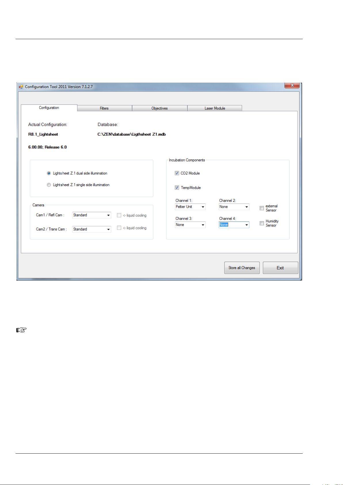
− On the Configuration tab (Fig. 6) you will find a Camera field with a drop – down menu for both
detector ports (Cam1, Cam2). Select the detection module(s) you are planning to use. When you
use the PCO.Edge, the checkbox liquid cooling will be marked automatically.
Fig. 6 ZEN Configuration Tool, Configuration tab
− Press the Store all Changes button and then exit the Configuration Tool. This will save the
changes you have made into the database of your system.
If you plan to exchange detection modules on a regular basis, it can be helpful to create two
databases, one for each detection module type. To do so, copy the original database with a
different name (you find it in the directory: C:\ZEN\database) and modify it with the Configuration
Tool accordingly. Make sure to always keep the original database. Name both databases, to easily
identify them. When ZEN is started open the Boot Status with the black arrow and then the
Hardware configuration database the same way (Fig. 7). Here you can choose which database
to use. The Recent… button shows all databases that have been used lately. The Choose… button
opens a window explorer window which allows one to search for a database to use.
14 000000-1790-528 02/2013
Page 19

CHAPTER 1 - HARDWARE
Lightsheet Z.1 User Interfaces Carl Zeiss
− Now start the ZEN (black edition) software
and perform the following tasks found in the
Maintain tab:
• Detector recognition
• Automatic Detector Alignment; and
if necessary
• Manual Detector Alignment.
− It might be necessary to adjust the focus
of the calibration grating (Fig. 8) for
the Automatic or Manual Detector
Alignment task. Start one of these tasks to
get a live image of the grating for evaluating
and adjusting the focus if applicable (see
section 3.2.2 Adjustment – Manual
Detector Alignment).
Fig. 7 ZEN Start-up window
3.2 Adjustment – Detector Recognition
When the detection modules are exchanged or attached to the Lightsheet Z.1 system for the first time,
the system must identify which detection module is present for which channel. Pressing the button
Detector recognition will start an identification routine to do this job. A progress bar is visible during
the process. When the Cancel button is pressed, the operation is aborted without saving any result. This
routine must be conducted before the Automatic or Manual Detector Alignment. At the end of this
process you be informed if the detector recognition had to perform any changes. If so, please restart the
ZEN software before continuing.
3.2.1 Adjustment – Automatic Detector Alignment
This adjustment is necessary for one or two detection modules, when:
• detection modules have been exchanged
• reflector turrets have been removed and inserted (restart ZEN before the alignment task)
• recognition of a pixel shift between channels
• the zoom is not centered.
No sample should be present. The necessary correction plate and grating is present for each channel
within the system and needs no additional activation.
The Automatic Detector Alignment will align the image center with the detection module center (zoom
center). For two detection modules, it will additionally align both to have overlapping pixels.
After detection module exchange, first press the Detector recognition button in the Adjustment
tool window.
02/2013 000000-1790-528 15
Page 20
CHAPTER 1 - HARDWARE
Carl Zeiss User Interfaces Lightsheet Z.1
After pressing the Automatic Detector Alignment button, a wizard window (Fig. 8) will open that
guides you through the process. Press the Next button after each step to continue or the Previous
button to move one step back. If you press Cancel you will abort the process without saving any results.
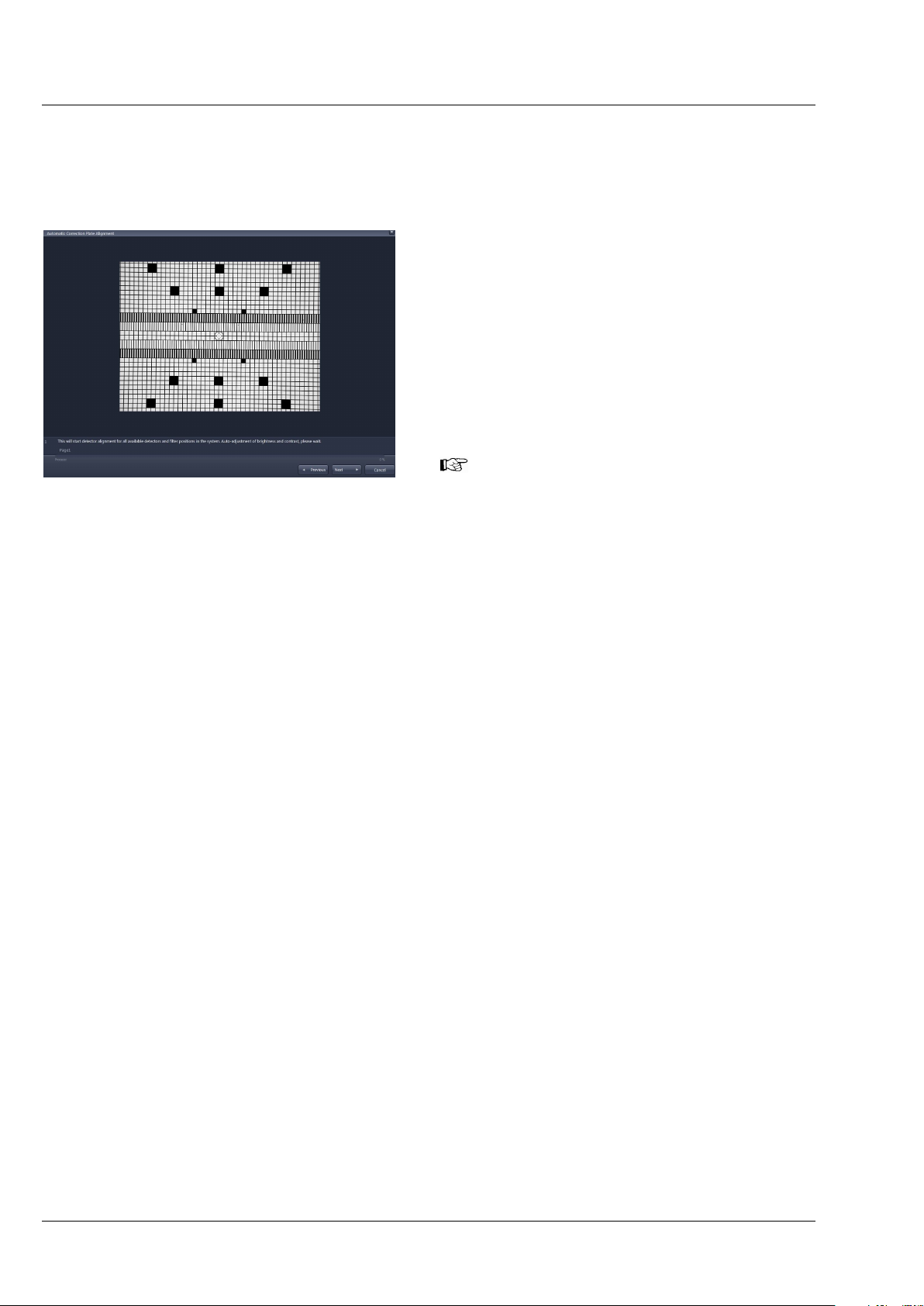
The first step (Fig. 8) automatically positions the
necessary grating into the light path and adjusts
brightness and contrast. A progress bar is present
in the lower part of the window. You can follow
the process in the displayed live image. You find
the following text below the live image:
“This will start detector alignment for all available
detectors and filter positions in the system. Autoadjustment of brightness and contrast, please
wait.”
If the live image of the grating shows the
grid pattern out-of-focus, cancel the
Fig. 8 Automatic Detector Alignment, first
step
Automatic Camera Alignment wizard and
first manually adjust the focus of the grating.
The necessary steps are described in section
3.2.3 Adjust the Grating Focus for the
Automatic or Manual Detector
Alignment Tool.
In Step 2 the movement of the correction plates is calibrated for both channels. There is no interaction
needed. Press the Next button to continue after the task is done. The following text is displayed:
“Calibration of correction plate movement, please wait.”
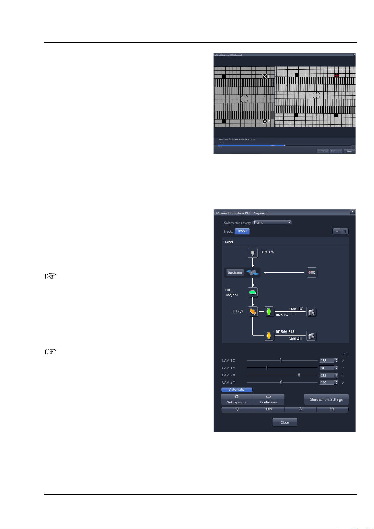
In Step 3 the zoom center is determined. A graphic of the grating is displayed at the left hand side of the
window (Fig. 9). Two squares are labeled with white crosses in this image. On the right hand side, a live
image of the grating is shown. Now mark the same squares as shown in the graphic in the live image by
simply clicking on them with the left mouse button. This will be repeated for a second zoom step. The
following text will be shown: “Determining the detector center. Please click on the two squares in the
right live image of the grid that are shown with the white cross within the left image display. Repeat for
both zoom settings, then continue.”
16 000000-1790-528 02/2013
Page 21
CHAPTER 1 - HARDWARE
Lightsheet Z.1 User Interfaces Carl Zeiss
Step 4 is the final step in which the alignment for
all filters and detection module channels is
performed. A progress bar is present at the bottom
of the window. When the procedure is finished the
Finish button becomes available, press it to save
all adjustments and leave the wizard. This text is
displayed: “Detector Alignment for all available
filters in progress, please wait.”
If you still encounter pixel shifts between the two
channels after the Automatic Camera Alignment
tool, you can fine tune settings using the Manual
Detector Alignment tool, see section 3.2.3 Adjust
the Grating Focus for the Automatic or
Manual Detector Alignment Tool.
Fig. 9 Automatic Detector Alignment,
third step
3.2.2 Adjustment – Manual Detector Alignment
This adjustment is necessary for one or two
detection modules when you recognize a pixel shift
between channels, or when the zoom is not
centered.
The Automatic Detector Alignment
should always be performed first since it
might already solve the problems.
Furthermore it defines the settings for the
combination Channel 1 (Cam1) and
position 1 of the Emission Selection Filter,
which should be used as the reference
during the Manual Detector Alignment.
The Zoom in the Acquisition tool window
is fixed to 1 while performing the Manual
Detector Alignment.
Fig. 10 Manual Detector Alignment
window
02/2013 000000-1790-528 17
Page 22
CHAPTER 1 - HARDWARE
Carl Zeiss User Interfaces Lightsheet Z.1
No sample should be present when performing this task. When pressing the Manual Detector
Alignment button, a window will open (Fig. 10). A grating is automatically inserted into the light path
and a live image of it is shown in a new image container within the ZEN software. The Set Exposure
button is activated automatically to adjust brightness. All components of the light path can be controlled
in the Manual Detector Alignment window. The light source is the LED white light source to ensure
the visibility of the grating independent of the filters in the light path. All other controls for adjusting
imaging settings should be controlled in the tool windows of the main software.
The activated (blue) Automatic button loads the
settings which have been previously defined with
the Automatic Detector Alignment for each light
path.
After pressing the Continuous button in the
Manual Detector Alignment window or in the
Main tool tabs a new image will open with a live
image of the grating (Fig. 11)
Fig. 11 Manual Detector Alignment,
Grating at Zoom 1
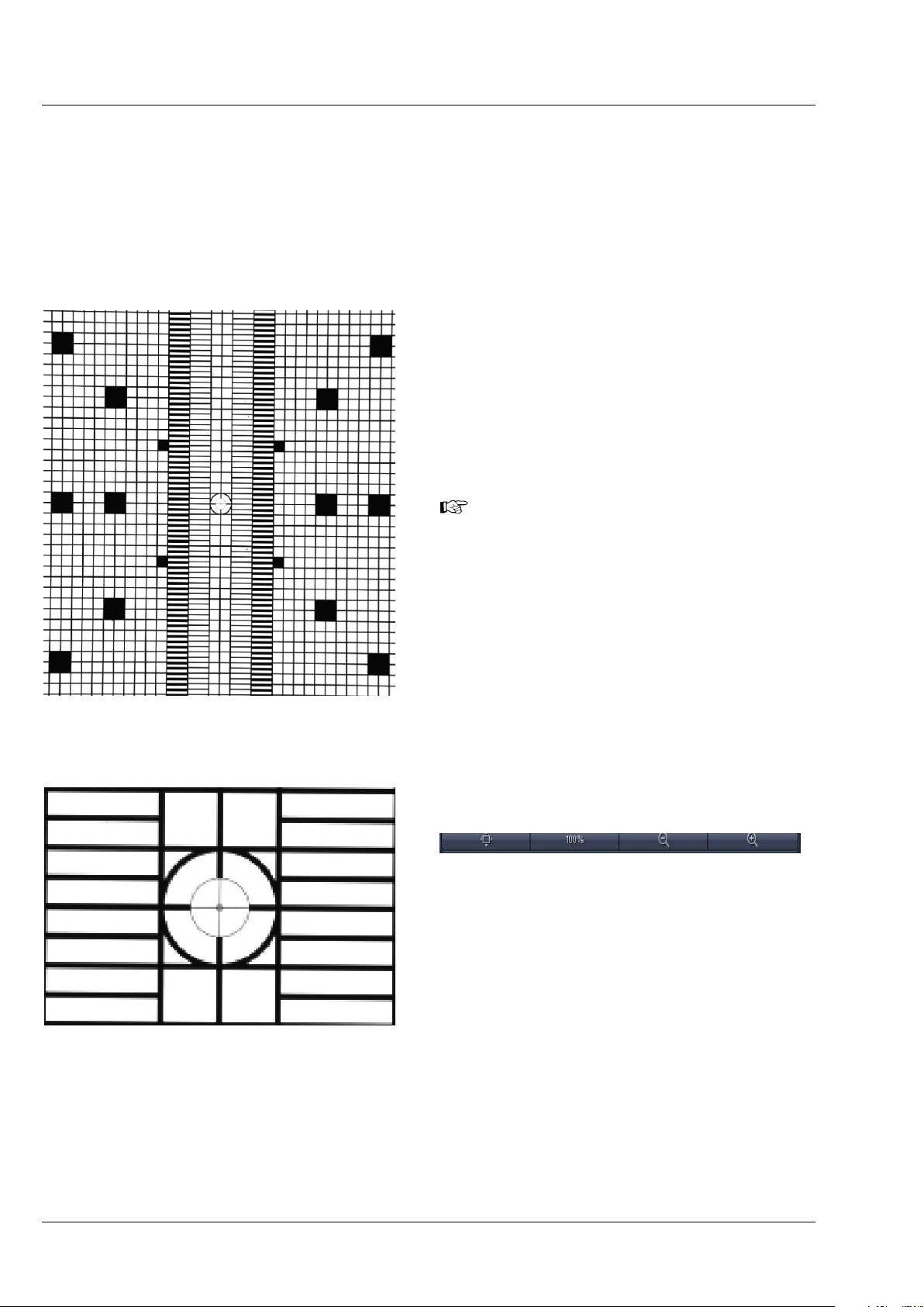
When the grating is out of focus, you need
to refocus it for the relevant channel by
performing the steps described in section
3.2.3. To check the focus, zoom into the
image using the Zoom function and look at
the center cross within the square (Fig. 12). If
the white portions within the inner most
circle are recognizable, the grating is in
focus.
To zoom into the image you can use these
buttons:
As a reference, the combination of Emission
Selection filter position 1 and Cam 1 should be
taken (see above). This combination should be the
first live image. Here mark a structure close to the
middle of the circled cross using the Graphics
View control. This cross will be the reference for
the following steps.
Now change the light path to the combination of
Fig. 12 Manual Detector Alignment,
Grating, center part zoomed in
Emission Selection filter and Channel (Cam 1 or
Cam 2) that you wish to adjust. The live image will
now show the grating with the current settings.
18 000000-1790-528 02/2013
Page 23
CHAPTER 1 - HARDWARE
Lightsheet Z.1 User Interfaces Carl Zeiss
Use the sliders or the input box with arrows of Cam 1 X and Cam 1 Y (for Channel 1, Cam1) or Cam 2 X
and Cam 2 Y (for Channel 2, Cam 2) to move the previously chosen structure of the grating to overlay
with the cross. Finish this step by pressing the Store Current Settings button.
Repeat the procedure for all desired Emission Selection filters and channels, always using the cross
marker as the reference.
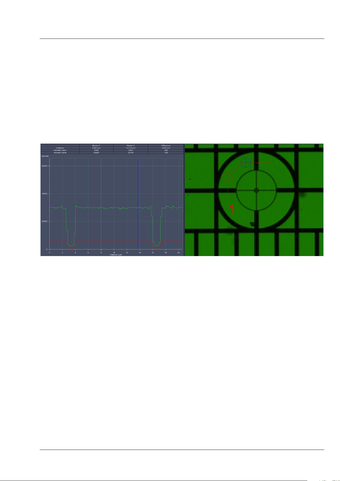
It is helpful, especially after an Automatic Detector Alignment has been performed, to use the Profile
View tab in order to evaluate if the image of Cam 1 and Cam 2 overlay. While the grating is
continuously imaged, press the Profile View tab and draw a line or an arrow poly-line on the grating
(Fig. 13). Use the sliders or the input box with arrows of Cam 1 X and Cam 1 Y (for Channel 1, Cam1) or
Cam 2 X and Cam 2 Y (for Channel 2, Cam 2) to move the lines of the grating to overlay each other.
Fig. 13 Manual Detector Alignment, Grating, Profile view tab
You can leave the Manual Detector Alignment by pressing the Close button at the bottom of the
window.
3.2.3 Adjust the Grating Focus for the Automatic or Manual Detector Alignment Tool
During the Automatic Detector Alignment tool wizard and the Manual Detector Alignment tool a
grating is brought into the light path which can be imaged on each channel. When the grating is out-offocus, you need to refocus it for the relevant channel. For checking the focus, it helps to zoom into the
image using the Zoom function and look at the center cross within the square (Fig. 12) If the white
portions within the inner most circle are recognizable, the grating is in focus.
To adjust the focus of the grating start the Manual Detector Alignment by pressing the button in the
Adjustment tool window. The grating will be brought into the beam path and an image is generated
and displayed in the image container of the main software.
02/2013 000000-1790-528 19
Page 24
CHAPTER 1 - HARDWARE
Carl Zeiss User Interfaces Lightsheet Z.1
Set focus for Cam 1 (Channel 1)
• Use the Light Path of the Manual Detector Alignment to first activate channel 1 (Cam1) and press
afterwards the Continuous button. The resulting live image shows the grating on channel 1 (Cam1).
• Use the Zoom tools of the Manual Detector Alignment to zoom into the center region of the image.
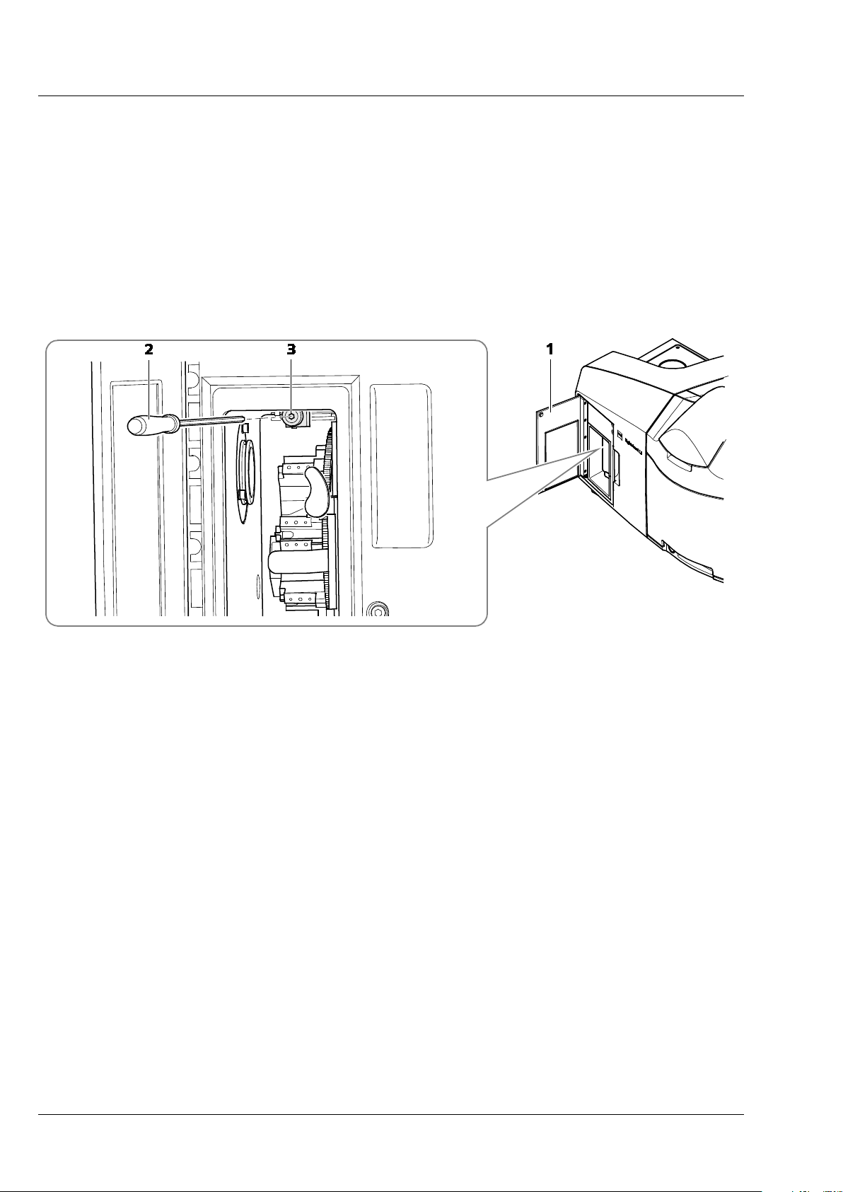
• With the live image running, open the front system door (Fig. 14/1) to the reflector turret for
emission filter selection. This system door has no safety interlock, and opening it will not terminate
image acquisition.
• Turn the screw which is above the turret (Fig. 14/3) with the long Allen wrench (Fig. 14/2).
1 Front system door
2 Allen wrench
3 Screw
Fig. 14 Position of the screw to adjust the focus of the grating for Cam 1 (channel 1)
• Monitor the live image of the grating while you turn the screw in any direction and find the position
of the screw that results in the sharpest image.
• Stop the continuous scan and close the front system door.
Set focus for Cam 2 (Channel 2)
• Use the Light Path of the Manual Detector Alignment to direct light towards channel 2 and
activate channel 2 (Cam2).
• Press afterwards the Continuous button. The resulting live image shows the grating on channel 2
(Cam2).
• Use the Zoom tools for the Manual Detector Alignment to zoom into the center region of the image.
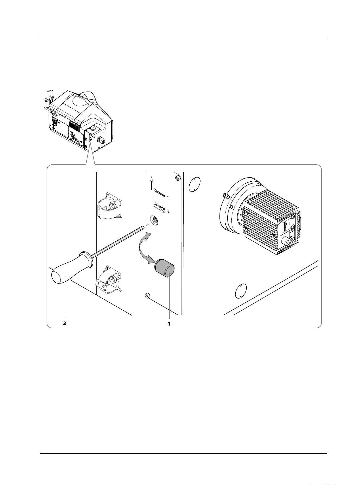
• While the imaging continues remove the black screw cap (Fig. 15/1) on the back of the main system
module Lightsheet Z.1. This opening gives way to a screw that can be turned with an Allen wrench
(Fig. 15/2).
20 000000-1790-528 02/2013
Page 25
CHAPTER 1 - HARDWARE
Lightsheet Z.1 User Interfaces Carl Zeiss
• Monitor the live image of the grating while you turn the screw in any direction and find the position
of the screw that results in the sharpest image.
• Stop the continuous scan and place the black screw cap back on the system.
1 Black screw cap
2 Allen wrench
Fig. 15 Position of the screw to adjust the focus of the grating for Cam 2 (channel 2)
02/2013 000000-1790-528 21
Page 26
CHAPTER 1 - HARDWARE
Carl Zeiss User Interfaces Lightsheet Z.1
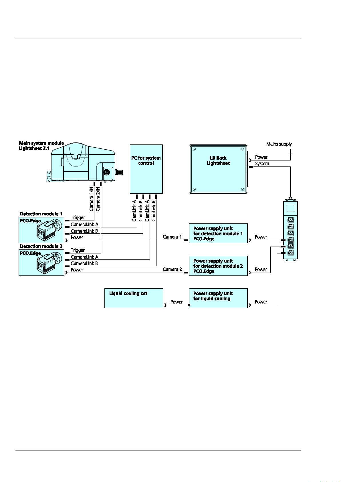
3.2.4 Cable Connections for the Detection Module "PCO.Edge"
The detection module "PCO.Edge" is equipped with a liquid cooling system. Please read the safety notes
of the Lightsheet Z.1 system, as well as the separate safety data sheet for the liquid cooling system. The
power supply unit (PSU) for the cooling is connected to the system's power strip at the rear of the laser
module. The cooling hoses should be as short as possible. The connection creates a closed circuit, starting
from the cooling unit leading to the detection module 1 (approx. 200 cm hose length) reflection port
(Cam1). From the latter a hose (approx. 200 cm) leads either back to the cooling unit or, if a second
detection module is used, first to the transmission port (Cam2) (approx. 100 cm) and then a third hose
(approx. 200 cm) leads back to the cooling unit.
Fig. 16 Cable connections for the detection module "PCO.Edge"
The detection module cables are connected as follows:
− CameraLink cables A and B are each plugged into the PC for system control. The upper slots of the
PC for system control are assigned to the detection module of the reflection port (Cam1), [CamLink
A] right and [CamLink B] left. The lower slots are assigned to the transmission port (Cam2),
[CamLink A[ right and [CamLink B] left.
− The power cable is connected to the power strip of the system on the rear of the LB Rack
Lightsheet.
− The trigger cable is always connected to the detection module with [1/IN] and on the rear side of
the main system module Lightsheet Z.1 to [Camera 1/IN] (refection port, Cam1) or [Camera 2/IN]
(transmission port, Cam2).
− The detection module is switched on with the toggle switch on the module itself.
22 000000-1790-528 02/2013
Page 27
CHAPTER 1 - HARDWARE
Lightsheet Z.1 User Interfaces Carl Zeiss
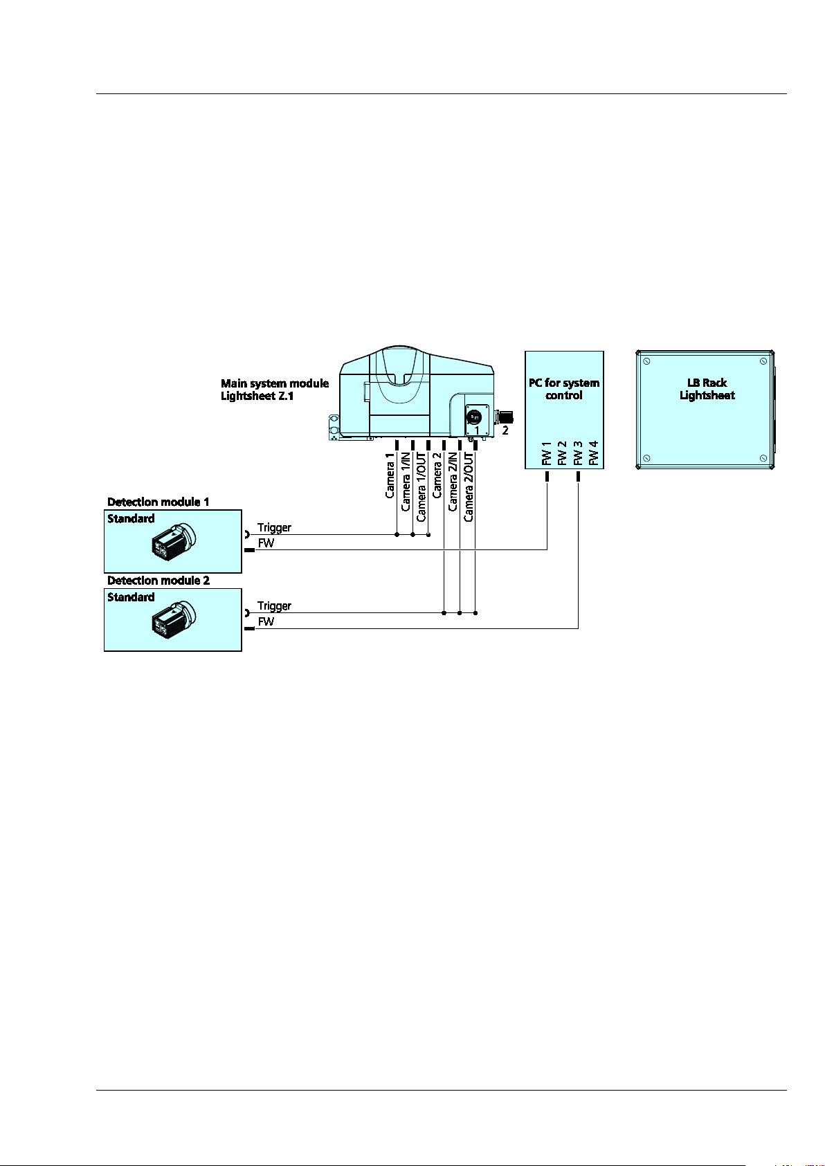
3.2.5 Cable Connections for the Detection Module "Standard"
− The following connections exist for this detection module:
− The firewire cable must be plugged into the PC for system control. There are four firewire sockets
on the PC for system control; the detection module from the reflection port (Cam1) is connected to
position [FW 1], from the transmission port (Cam2) to position [FW 3].
− The trigger cable is plugged into the respective detection module and the three ends on the rear
side of the main system module Lightsheet Z.1 to [Camera 1] or [Camera 2], as well as [Camera
1/IN] and [Camera 1/OUT] (reflection port, Cam1) or [Camera 2/IN] and [Camera 2/OUT]
(transmission port, Cam2).
Fig. 17 Cable connections for the detection module "Standard"
02/2013 000000-1790-528 23
Page 28

CHAPTER 1 - HARDWARE
Carl Zeiss User Interfaces Lightsheet Z.1
3.3 Assembly of the Sample Chamber
− Wear powder-free gloves to avoid fingerprints on the cover slips as well as to protect your hands
from sharp edges.
3.3.1 Assembly of the Sample Chamber Windows
− Assemble the three sample chamber body windows (for the illumination optics on the sides and
the front chamber window for the overview camera with LED white illumination) using the
following steps:
1 Sample chamber body
2 Cover slip
3 O-ring (18 mm O-ring, black)
4 Illumination adapter ring
5 Sample chamber window tool
Fig. 18 Assembly of the three sample chamber windows for illumination optics and overview
camera
1. Take the sample chamber body (Fig. 18/1) and lay it onto the table so that one of the three smaller
windows are facing you.
2. Using a forceps or gloved hands, remove one clean circular 18 mm cover slip; place cover slip into
the empty sample chamber body window so it fits into the smallest groove (Fig. 18/2) – you will
need a fine forceps.
3. Now place the O-ring (18 mm O-ring, black) into the corresponding groove (Fig. 18/3). Make sure
not to disturb the positioning of the cover slip.
4. Take the silver illumination adapter ring (Fig. 18/4) and lay it into the window making sure the flat
side with the four pinholes is facing you.
5. Using the sample chamber window tool (Fig. 18/5), position the circular pins into the pinholes and
turn clockwise until finger-tight. Adapter should be flush with the sample chamber body.
24 000000-1790-528 02/2013
Page 29

CHAPTER 1 - HARDWARE
Lightsheet Z.1 User Interfaces Carl Zeiss
6. Repeat step 1 - 6 for each of the three windows.
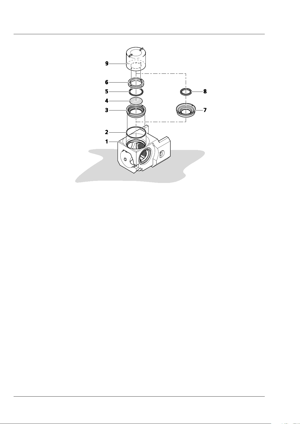
− Assemble the sample chamber window for the detection optic.
1. Turn the sample chamber body (Fig. 19/1) to the largest opening window for the detection
optics.
2. Using a small spatula or the opposite end of a forceps position the blue O-ring tightly into
the groove to ensure no leaking (Fig. 19/2).
3. Assemble the chamber window for the detection optic according to the following steps.
Depending on the detection optics used, insert the correct detection optic adapter:
4. For the detection optic 5x/0.16:
a) Place the large silver detection optic adapter 5x (Fig. 19/3) onto the table with the
grooves facing you.
b) Remove one clean circular 18 mm glass cover slip; place cover slip (Fig. 19/4) into
the large silver detection optic adapter 5x (Fig. 19/3) making sure it is positioned
into the smallest groove – adjust the coverslip position with the forceps if necessary.
c) Now place the O-ring (18 mm O-ring, black) into the corresponding groove on top
of the cover slip (Fig. 19/5).
d) Take the silver retaining ring (Fig. 19/6) and place it inside the detection optics
adapter 5x with the flat side with two notches facing you. Using the circular pin-side
of the sample chamber window tool (Fig. 19/9), turn clockwise until finger-tight.
e) Placing the assembled detection optic adapter 5x into the sample chamber body
window. Using the squared pins of the sample chamber window tool, turn clockwise until finger-tight.
5. For the detection optic 20x/1.0, 40x/1.0, 63x/1.0:
a) Use the corresponding detection optic adapter (see the detection optic adapter
catalogue number and magnification engraving) (Fig. 19/7).
b) Insert the detection optic adapter into the sample chamber body window for
detection with the flat side facing you.
c) Using the sample chamber window tool (squared pin-side) (Fig. 19/9) turn adapter
clock-wise until finger-tight.
d) Take a 15 mm black O-ring (Fig. 19/8) and position the O-ring into the groove inside
the middle of the detection optic adapter using the blunt end of a forceps if
necessary.
02/2013 000000-1790-528 25
Page 30
CHAPTER 1 - HARDWARE
Carl Zeiss User Interfaces Lightsheet Z.1
1 Sample chamber body
2 O-ring (blue)
3-6 For the detection optic 5x/0.16
− 3 Detection optic adapter 5x/0.16
− 4 Cover slip
− 5 O-ring (18mm O-ring, black)
− 6 Retaining ring
7-8 For the detection optic 20x/1.0, 40x/1.0, 63x/1.0
− 7 Detection optic adapter (20x/1.0, 40x/1.0, 63x/1.0
− 8 O-ring (15mm O-ring, black)
9 Sample chamber window tool
Fig. 19 Assembly of sample chamber window for the detection optic
26 000000-1790-528 02/2013
Page 31

CHAPTER 1 - HARDWARE
Lightsheet Z.1 User Interfaces Carl Zeiss
3.3.2 Assembly of the Sample Chamber Body and the Sample Chamber Dove Tail Slide
1 Mesh screen
2 Sample chamber body
Fig. 20 Placing the mesh screen
− Place the mesh screen (Fig. 20/2) into the middle of the sample chamber body (Fig. 20/1) to reduce
turbulence stress on the specimen when the chamber is filled.
− For cleaning, it can be carefully removed by a forceps or via a teflon-tip-free end of a capillary
plunger.
− If a Heating component is used, proceed first with chapter 3.7.1 (see PeCon manual for specific
heating component) and screw it onto the bottom of sample chamber body.
• The sample chamber body (Fig. 21/3) can now be attached to the sample chamber dove tail slide
(Fig. 21/1).
• Lay down the sample chamber dove tail slide with the two positioning pins facing upwards (Fig. 21/2).
• Take the sample chamber body and position it on to the sample chamber dove tail slide with the
detection optic adapter window facing to the back relative to the sample chamber dove tail slide grip.
• Invert the sample chamber body with the sample chamber dove tail slide so that the four screw-holes
(Fig. 21/4) that were on the bottom are now facing you.
• Insert the four screws (diameter = M3, length = 14 mm) (Fig. 21/5) into the four screw-holes and
tighten using and Allen wrench (2.5).
02/2013 000000-1790-528 27
Page 32

CHAPTER 1 - HARDWARE
Carl Zeiss User Interfaces Lightsheet Z.1
1 Sample chamber dove tail slide
2 Positioning pins
3 Sample chamber body
4 Screw-holes
5 Screws (diameter = M3, length = 14 mm)
Fig. 21 Assembly of the sample chamber body and the sample chamber dove tail slide
28 000000-1790-528 02/2013
Page 33

CHAPTER 1 - HARDWARE
Lightsheet Z.1 User Interfaces Carl Zeiss
3.3.3 Insertion of the Drain Connector, Luer-Lock Connectors and Blind Plugs
− Turn the assembled sample chamber body with dove tail slide so that the dove tail slide is on the
table with the grip facing you (Fig. 22/1).
− Take the grey drain connector and screw this into the upper left hole of the sample chamber body
until finger-tight (Fig. 22/6). This will guide excess liquid to the drain.
− Take a Luer-Lock-connector (white) and screw it into the lower right corner of the sample chamber
body (Fig. 22/4). The Luer Lock connectors (white) are used to fill or perfuse the sample chamber
with liquids and / or gasses.
− For CO
incubation, the Luer-Lock connector must be positioned at the upper right corner of the
2
sample chamber (Fig. 22/2). For syringe based perfusion one can use any of the three lower screw
holes. The lower right corner screw hole is recommended for convenience (Fig. 22/4).
− For perfusion pump use the right side bottom screw hole for the perfusion input and either of the
front lower corner screw holes for the perfusion output.
− Close all remaining sample chamber screw hole openings by inserting the black blind plugs
(Fig. 22/3; Fig. 22/5).
1 Sample chamber body with dove tail slide
2 Luer-Lock-connector (white); position recommend for CO
3 Blind plug (black)
4 Luer-Lock-connector (white); position recommend for syringe based perfusion
5 Blind plug (black)
6 Drain connector (grey)
Fig. 22 Insertion of the Drain connector, Luer-Lock-connectors and Blind plugs
incubation
2
02/2013 000000-1790-528 29
Page 34

CHAPTER 1 - HARDWARE
Carl Zeiss User Interfaces Lightsheet Z.1
3.3.4 Insertion of Accessories for Incubation
• A temperature sensor (Fig. 23/1) can be used in the sample chamber body.
− Hold the temperature sensor so that it shows you the letter “J”. Slide the temperature sensor
sleeve (Fig. 23/3) onto the top horizontal part of the J-shaped temperature sensor.
− Dip the temperature sensor with sleeve into the sample chamber body and position the
temperature sensor sleeve securely into the sample chamber body groove (Fig. 23/2).
1 Temperature sensor
2 Sample chamber body groove
3 Temperature sensor sleeve
Fig. 23 Insertion of temperature sensor
− Place a cover on top of the sample chamber body (Fig. 24/3). This will minimize evaporation of
medium or contamination of the sample chamber. If CO
module Lightsheet Z.1 is used
2
(configuration dependent, chapter 2.7.2) the cover is recommended to maintain the CO
concentrations.
− Keep the opening as small as possible. Use the 3 mm opening cover for capillaries (Fig. 24/1) and
7 mm opening cover for syringes (Fig. 24/2). The cover only rests on top of the sample chamber
body and is free to move.
gas
2
30 000000-1790-528 02/2013
Page 35

CHAPTER 1 - HARDWARE
Lightsheet Z.1 User Interfaces Carl Zeiss
1 Cover for capillaries (3 mm opening)
2 Cover for syringes (7 mm opening)
3 Sample chamber body with dove tail slide
Fig. 24 Placing cover on top of the sample chamber body
3.4 Removing and Inserting the Sample Chamber
The sample chamber can be removed from the system. For removal, proceed as follows:
− Open the front system cavity door (Fig. 25/1) of the main system module Lightsheet Z.1.
− Remove the liquid from the sample chamber (Fig. 25/6) using the hose with the corresponding
syringe (Fig. 25/9).
− Ensure that no sample protrudes into the sample chamber. Remove the sample, if necessary,
through the upper sample opening (Fig. 25/2) below the upper system cavity door (Fig. 25/3).
− If necessary, remove the connections for the incubation device (Fig. 25/8).
− Loosen the screw (Fig. 25/4) on the sample chamber and pull the sample chamber out by the grip
(Fig. 25/5).
− Inserting the sample chamber:
− Take hold of the sample chamber by the lower grip (Fig. 25/5) and push the sample chamber
(Fig. 25/6) into the guide rails (Fig. 25/7).
− Tighten the screw (Fig. 25/4) without exerting force. The sample chamber has been correctly
inserted when its lower edge is flush with the guide rail.
− Plug in the cable to the incubation unit (Fig. 25/8) as necessary.
02/2013 000000-1790-528 31
Page 36

CHAPTER 1 - HARDWARE
Carl Zeiss User Interfaces Lightsheet Z.1
1 Front system cavity door 6 Sample chamber
2 Upper sample opening 7 Guide rails
3 Upper system cavity door 8 Connections for incubation
4 Securing screw 9 Hose and syringe
5 Sample chamber grip
Fig. 25 Removing and inserting the sample chamber
/ sample chamber mount
3.5 Assembly of the Sample Holder
Depending on the size of the sample there are two different types of sample holders available: sample
holder for capillaries (inner diameter of capillary size 1 / ~0.68 mm, size 2 / ~1 mm, size 3/ ~1.5 mm,
size 4 / ~2.15 mm) and syringes (1 ml). Always use the minimal cylinder diameter necessary for your
specimen size to avoid excessive amounts of embedding medium.
3.5.1 Assembly of the Sample Holder for Capillary
1. Select the corresponding colored sleeves (Fig. 26/3) to match the color of the capillary of choice
(Fig. 26/6).
2. The capillary should hold the sample and the appropriate plunger (Fig. 26/5), see as well the
CHAPTER 2 SAMPLE PREPARATION in this manual. The plungers that fit into capillary size 2 - 4
have to be used with corresponding Teflon tips that are already assembled onto the plungers. Note
that in addition 10x Teflon tips of each as well as matching Teflon tip tools are provided in the
Chamber & Sample Holder Starter Kit Lightsheet Z.1 (Tab. 1). The Teflon tips can be assembled as a
replacement onto the matching tip-less plungers.
32 000000-1790-528 02/2013
Page 37

CHAPTER 1 - HARDWARE
Lightsheet Z.1 User Interfaces Carl Zeiss
Capillary size
(inner diameter)
Capillary
Color coding/
Plunger
Reference number
Teflon tip Teflon tip too
Color coding
Reference number
Size 1 (~0.68 mm) Red/701902 #701996 - -
Size 2 (~1mm) Black/701904 #701997 Size 2 Clear
Size 3 (~1.5mm) Green/701908 #701998 Size 3 Green
Size 4 (~2.15mm) Blue/701910 #701999 Size 4 Blue
Tab. 1 Capillary components in the Chamber & Sample Holder Starter Kit Lightsheet Z.1
3. The sleeves are tube-shaped with four slits at one end. Insert the sleeves into the capillary sample
holder stem (Fig. 26/2) so that the two slit endings point outwards and the non-slit endings face
toward the center.
4. Take the clamp screw (Fig. 26/4) and position it onto the capillary sample stem holder turning
clockwise three times (360° each turn).
1 Sample holder disc for capillaries 5 Plunger
2 Capillary sample holder stem 6 Capillary with color-coded marking
3 Sleeves (color-coded) 7 Ejection tool
4 Clamp screw
Fig. 26 Assembly of the sample holder for capillary
02/2013 000000-1790-528 33
Page 38

CHAPTER 1 - HARDWARE
Carl Zeiss User Interfaces Lightsheet Z.1
5. Take the capillary by the glass portion (avoiding the plunger) with the agarose embedded specimen
inside and carefully place it into the center of the clamp screw sample holder top.
6. Push the capillary within the holder downwards until the color-coded capillary marking becomes
visible (Fig. 26/6 right hand side).
Newly bought sleeves can be slightly tight at their slit opening ends so that in can be difficult to
push the capillary within the holder. In this case take the capillary with matching plunger and insert
it carefully into the corresponding sleeves at their non-slit endings. Make sure that the slits point
outwards. Position the capillary surrounded by the sleeves into the sample holder stem and place
the clamp screw. You can proceed with step 6).
7. Tighten the clamp screw. Take the sample holder disc (Fig. 26/1) with the protruding side with
positioning notch facing you. Carefully position the capillary stem holder with specimen into the
sample disc holder until the ball bearing click-position is felt.
8. Before taking the capillary out (chapter 2.6), retract the sample back inside the capillary glass via
using plunger.
9. For removal, loosen the clamp screw and carefully pull the capillary through the stem sleeve by
using the glass end nearest the color-coded marking.
10. Unscrew the clamp screw completely and remove the sleeves by using the ejection tool (Fig. 26/7)
for the capillary sleeves removal.
The sleeves as well as the glass portion of the capillary can be cleaned with a lint-free cloth moistened
with water.
3.5.2 Assembly of Sample Holder for Syringes
− Place the sample holder disc for syringes (Fig. 27/1) so the flat side is facing you.
− Take the adapter ring (Fig. 27/2) and place it into the center of the sample holder disc with the
larger diameter of the ring facing you.
− Pick up the sample disc holder with adapter ring in one hand. Take the syringe carrying your
specimen (Fig. 27/3) and insert it completely into the sample disc holder (avoiding touching the
plunger).
− Touching the syringe body and turn clock-wise to position the syringe body into the two clamps
(Fig. 27/6).
34 000000-1790-528 02/2013
Page 39

CHAPTER 1 - HARDWARE
Lightsheet Z.1 User Interfaces Carl Zeiss
1 Sample holder disc for syringes 4 Ball bearings
2 Adapter ring 5 Syringe body
3 Syringe 6 Clamp
Fig. 27 Assembly of sample holder for syringes
3.6 Inserting and Removing the Sample Holder
• To insert the sample holder move the stage of
the Lightsheet Z.1 system to the Load position
via the Specimen Navigator tool (Fig. 28) in
the ZEN software (see CHAPTER 4 SYSTEM
OPERATION).
• Open the upper system cavity door (Fig. 28/1).
• Take the sample holder for capillaries or syringes by the sample holder disc with the capillary or the
syringe facing downwards (Fig. 29/3).
Fig. 28 Load Position in the Specimen
Navigator
• Insert the sample holder gliding the sample holder disc along the guide rails (Fig. 29/2). It is placed
correctly into a click position if the sample holder disc ball bearings lock into the three holes.
• Notice the white line marking at the outer edge of the disc. It can be used as a reference point for
reorienting the sample holder disc once it was taken out.
• Close the upper system cavity door (Fig. 29/1) and position the capillary and the sample as described in
CHAPTER 4 SYSTEM OPERATION.
02/2013 000000-1790-528 35
Page 40

CHAPTER 1 - HARDWARE
Carl Zeiss User Interfaces Lightsheet Z.1
1 Upper system cavity door
2 Guide rails
3 Capillary
4 Hole for disc ball bearings
Fig. 29 Inserting the Sample Holder
− Before taking the sample holder out, retract the sample back inside the capillary glass via using
plunger.
− Move to the Load position via the Specimen Navigator tool (Fig. 28) in the ZEN software (see
CHAPTER 4 SYSTEM OPERATION).
− Open the upper system cavity door (Fig. 29/1).
− Take the sample holder out by gliding the sample holder disc along the guide rails (Fig. 30).
Fig. 30 Removing the Sample Holder
36 000000-1790-528 02/2013
Page 41

CHAPTER 1 - HARDWARE
Lightsheet Z.1 User Interfaces Carl Zeiss
3.7 Installation of the Incubation Modules
The incubation of the Lightsheet Z.1 is configuration dependent. It is used to control and monitor
temperature and CO
various configurations.
− The configuration dependent modules should be placed on a level surface next to the system and
are stacked on top of each other (Fig. 31). For further information see the individual component
manuals from PeCon.
The installation of incubation modules on the
Lightsheet Z.1 can be divided into two parts. One
deals with the actual assembly of hardware
components of the incubation modules and their
connections to the system. The second part deals
with the registration of the incubation modules
using specific software tools.
supply to the sample environment. The TempModule S1 is required for all of the
2
Fig. 31 Incubation modules stacked on top
of each other
3.7.1 Heating Components
There are two different heating components available: (1) Heating Block Sample Chamber
Lightsheet Z.1 enables to heat the sample chamber from ambient temperature to 42 °C. (2) Peltierblock
Sample Chamber Lightsheet Z.1 permits heating and cooling of the sample chamber in the range from
10 °C to 42 °C.
(1) Heatingblock Sample Chamber Lightsheet Z.1 is controlled by the TempModule S1 providing
electrical power supply and closed-loop temperature control. The system allows to heat the sample
chamber from ambient temperature to 42 °C.
Connect the Heating Block LSFM and the TempModule S via connecting cable. For proper electrical
connection please follow the connection diagram in the individual component manuals from
PeCon.
02/2013 000000-1790-528 37
Page 42

CHAPTER 1 - HARDWARE
Carl Zeiss User Interfaces Lightsheet Z.1
Make sure that the temperature inside the sample chamber is in accordance with the desired
temperature value required for the experiment. The ZEN software displays the temperature of the
heating block itself and does not register the actual temperature in the sample chamber that can
be lower (due thermal loss) or higher.
• To assemble the heating block to the sample chamber remove first of all the sample chamber dove tail
slide from the assembled sample chamber (Fig. 1, section 3.3.2 Assembly of the Sample Chamber
Body and the Sample Chamber Dove Tail Slide).
• Take the heating block and screw it onto the bottom of sample chamber body following the
instructions of the individual component manuals from PeCon.
• The sample chamber body can now be assembled together with the sample chamber dove tail slide
(Fig. 1, section 3.3.2).
• Insert the sample chamber as described in chapter 2.4 and plug in the 8 pin connector of the
connection cable into the right side of the front system cavity / sample room following the individual
component manuals from PeCon (Fig. 32/6) shows the connection exemplary for the Peltier Block S).
(2) Peltier Block S is part of the TempModule CZ-LSFM. The Peltier Block helps adjust the sample
chamber temperature by heating or cooling the sample chamber within the range of 10 °C to 42 °C (up
to 1.5°/min heating, up to 1.0°/min cooling). The temperature inside the sample chamber is monitored by
a temperature sensor (Fig. 23/1; Fig. 32/3). For insertion of the temperature sensor in the sample
chamber refer to section 3.3.4 Insertion of Accessories for Incubation).
The TempModule CZ-LSFM contains a water based coolant reservoir. For safety reasons (Risk of
electrical shock as a result of leakage) the unit must be placed directly on a level table and is thus
the base for all other incubation related modules (Fig. 31).
− Connect the TempModule S, the TempModule CZ-LSFM, the Lightsheet Z.1 and the Peltier Block
according to the individual component manuals from PeCon.
− To assemble the Peltier Block to the sample chamber remove first of all the sample chamber dove
tail slide from the assembled sample chamber (section 3.3.2; Fig. 21).
− Take the Peltier Block and screw it onto the bottom of sample chamber body following the
instructions of the individual component manuals from PeCon.
− The sample chamber body can now be assembled together with the sample chamber dove tail slide
(Fig. 21) and insert it into the Lightsheet Z.1 as described (section 3.3.2 ).
− Insert the accessories for incubation (temperature sensor, cover recommended) into the sample
chamber (section 3.3.4, Fig. 23, Fig. 24).
− Connect the Peltier Block (Fig. 32/6) to the Lightsheet Z.1 by the two provided silicone tubes
(Fig. 32/7-8) and plug in the 8 pin connector of the connection cable into the right side of the front
system cavity / sample room (Fig. 32). For proper electrical connections and tube connections follow
the instructions of the PeCon manual.
38 000000-1790-528 02/2013
Page 43

CHAPTER 1 - HARDWARE
Lightsheet Z.1 User Interfaces Carl Zeiss
Heating component Temperature range Incubation modules
Heating Block Heating from ambient
temperature to 42 °C
Peltier Block Heating and cooling in the
range from 10 °C to 42 °C
(1) TempModule S1
(2) Heating Block LSFM
(1) TempModule S1
(2) TempModule CZ-LSFM (including Peltier
Block and Temperature sensor)
Tabelle 1 Overview Heating components
3.7.2 CO
The CO
-Module Lightsheet Z.1 controls and monitors adjustable CO2 concentration (from 0 % to 10 %)
2
in the sample chamber and requires CO
-Module Lightsheet Z.1
2
supply, sterile filter and Humidifier S1 to provide CO2-enriched
2
air.
− At least 3h (or more) may be needed until a stable pH value is reached due to the small surface
area in relation to sample chamber volume.
− For assembly of hardware components of the CO
Module and its connections to the system, as
2
well as the calibration procedure needed follow the instructions from the PeCon manual.
− After CO
calibration, the Lightsheet Z.1 system must be completely turned off before work with
2
the system can continue.
− Position the Luer-Lock connector for CO
incubation at the top right corner of the sample chamber.
2
Place a cover on top of the sample chamber body (Fig. 24, chapter 3.3.4) to maintain the CO
concentrations.
− The sterility of the CO
sample chamber by following the cleaning instruction of all parts of the CO
-enriched air is given by the sterile filter. Take control of the sterility in your
2
-module (see PeCon
2
manual) as well as the components of the sample chamber (see CHAPTER 1 HARDWARE).
Please clamp all incoming or outgoing tubing (Fig. 32/2, Fig. 32/5, Fig. 32/9, Fig. 32/10) into the
provided clamping grooves. This will avoid possible disconnection problems after closing the front
system cavity door.
Note that for the sake of completeness Fig. 26 shows the connection diagram for the usage of a
perfusion pump (Fig. 32/5, Fig. 32/9). Alternatively a syringe based-perfusion can be used (position
Fig. 32/5). Consequently, Fig. 32/9 has to be replaced by a bling plug.
gas
2
02/2013 000000-1790-528 39
Page 44

CHAPTER 1 - HARDWARE
Carl Zeiss User Interfaces Lightsheet Z.1
1 Drain connector
2 Luer-Lock connector for CO
3 Temperature sensor with 4-pin connection cable
4 Blind plug
5 Luer-Lock connector for perfusion pump-in with tubing (or alternatively for syringe based perfusion)
6 Peltier Block S with 8-pin connector
7 Cooling liquid (Silicon tube with male connector)
8 Cooling liquid (Silicon tube with male connector)
9 Luer-Lock connector for perfusion pump-out with tubing
10 Drain connector with tubing
11 Drain tray
incubation with tubing
2
Fig. 32 Incubation connections for sample chamber body
-Module Lightsheet Z.1 can be extended with Heating Device Humidity S1 to improve thermal
CO
2
equilibrium in the sample chamber.
40 000000-1790-528 02/2013
Page 45

CHAPTER 1 - HARDWARE
Lightsheet Z.1 User Interfaces Carl Zeiss
3.7.3 Heating Device Humidity S1
For a better humidification of incubation atmosphere the Humidifier of the corresponding CO
-Module
2
Lightsheet Z.1 can be inserted into the Heating Device Humidity S1. The Heating Device Humidity S1
enables to improve thermal equilibrium in the sample chamber and avoid condensation in the tubing.
3.7.4 Registration of the incubation modules
• After the Lightsheet Z.1 and the PC for system control are turned on and the operation system has
booted start the software ZEN Configuration Tool. You find it either as a shortcut on your desktop or
in this directory : C:\ZEN\HWT as Configuration Tool 2012.exe.
• On the opening window press the Start configuring button (Fig. 33):
Fig. 33 ZEN Configuration Tool Start-up window
• On the Configuration tab (Fig. 34) you find an Incubation Components field with check boxes for
Module and TempModule that you can activate or deactivate depending on your incubation
CO
2
configuration. These modules will show up later as Atmosphere (%) panel and Temperature (
o
C)
panel respectively in the ZEN software (see CHAPTER 4 SYSTEM OPERATION).
02/2013 000000-1790-528 41
Page 46

CHAPTER 1 - HARDWARE
Carl Zeiss User Interfaces Lightsheet Z.1
Fig. 34 ZEN Configuration Tool Incubation Components field
• A drop-down menu enables to assign heating components (Heatingblock, Peltier Block) as well as the
Heating Device Humidity to four distinct channels.
Make sure that the assignment of incubation components to the corresponding channels in the
Configuration Tool is in accordance with the electrical connection of the incubation components
into the TempModule S1 (“Channel 1-4”, “Control Sensor”).
• We recommend to assign Channel 1 to the heating component (Heatingblock, Peltier Block) and
Channel 4 to the Heating Device Humidity if available.
• Do not check the check boxes for external Sensor as well as an Humidity Sensor. These
components are not part of the Lightsheet Z.1 incubation modules.
• Leave the Configuration Tool with the Store all Changes button. This will write all changes into the
database of your system.
42 000000-1790-528 02/2013
Page 47

CHAPTER 1 - HARDWARE
Lightsheet Z.1 illumination
optics 5× / 0.1
Lightsheet Z.1 illumination
optics 10× / 0.2
Lightsheet Z.1 User Interfaces Carl Zeiss
3.8 Switch Incubation ON and OFF
• Before you turn ON the incubation, all incubation components you wish to use during the imaging
session must be attached to the Lightsheet Z.1 system before starting ZEN software.
• Set the "Incubation" switch on the remote control to the ON position. Make sure that all incubation
components are switched on.
• Once ZEN is running you can detach and reattach components.
• To turn OFF the incubation, uncheck the corresponding checkboxes in the Incubator tool window
(see CHAPTER 4 SYSTEM OPERATIONl) or deactivate the incubation components by setting the
"Incubation" switch to the OFF position.
Be aware that all incubation components will continue working with the in Incubator tool window
specified parameters after ZEN has been shut down or stopped working. This will keep your sample
alive under precisely defined conditions, even if ZEN stops unexpected during an experiment.
3.9 Illumination and Detection Optics
In the Lightsheet Z.1, one or a pair of illumination optics plus one detection optic are always required.
We recommend the following combinations:
Lightsheet Z.1 detection optics
5× / 0.16
Lightsheet Z.1 detection optics
20× / 1.0
Lightsheet Z.1 detection optics
40× / 1.0
Lightsheet Z.1 detection optics
63× / 1.0
yes no
no yes
no yes
no yes
02/2013 000000-1790-528 43
Page 48

CHAPTER 1 - HARDWARE
Detection
Optic
0.36x
0.7x
1.0x
2.5x
Detection
Optic
0.36x
0.7x
1.0x
2.5x
Carl Zeiss User Interfaces Lightsheet Z.1
The area that can be imaged with the combination of detection optics with the detection module on the
Lightsheet Z.1 is summarized *
1)
in the following tables:
Zoom
x (µm) y (y
*2)
µm) x (µm) y (µm) x (µm) y (µm) x (µm) y (µm)
5× / 0.16 4815 4815 2496 2496 1733 1733 693 693
20× / 1.0 1204 1204 624 624 433 433 173 173
40× / 1.0 602 602 312 312 217 217 87 87
63× / 1.0 382 382 198 198 138 138 55 55
Tabelle 2 Detection module PCO.Edge
Zoom
x (µm) y
*2)
(µm) x (µm) y
*2)
(µm) x (µm) y (µm) x (µm) y (µm)
5× / 0.16 4157 5570 2138 2864 1497 2005 599 802
20× / 1.0 1039 1392 534 716 374 501 150 201
40× / 1.0 520 696 267 358 187 251 75 100
63× / 1.0 330 442 170 227 119 159 48 64
Tabelle 3 Detection module Standard
*1) Typical values for Lightsheet Z.1 systems
*2) Be aware, a homogenous light sheet illumination with full intensity is limited to about 2800 µm in the y direction. Above
and below this center, the illumination intensity will fade towards the edges in the y direction.
44 000000-1790-528 02/2013
Page 49

CHAPTER 1 - HARDWARE
Lightsheet Z.1 User Interfaces Carl Zeiss
3.9.1 Removing and Inserting the Illumination Optics Unit
The illumination optics unit (Fig. 35/2) can easily be removed and inserted after the removal of the sample
chamber (see section 3.4 Removing and Inserting the Sample Chamber).
To protect the front lenses, secure the appropriate protective caps (Fig. 35/3) over each of the
illumination optics (Fig. 35/2) and protective cap (Fig. 35/4) over the detection optic (Fig. 35/5). The
illumination optics can then be unscrewed by turning anticlockwise.
To insert the illumination optics, proceed in the reverse order by screwing it clockwise into the unit until
finger-tight.
Finally, the protective caps can be removed and the sample chamber inserted.
After the illumination optic has been exchanged, the currently used optic must be registered in the ZEN
software. The necessary software interface can be found in the Objectives tool window under the
Maintain tab.
1 Front system cavity door 4 Protective cap for detection optics unit
2 Illumination optics (2×) 5 Detection optics unit
3 Protective cap for illumination optics unit (2×) 6 Threaded shaft for illumination optics unit (r and l)
Fig. 35 Removing and inserting the illumination optics
02/2013 000000-1790-528 45
Page 50

CHAPTER 1 - HARDWARE
Carl Zeiss User Interfaces Lightsheet Z.1
3.9.2 Removing and Inserting the Detection Optics Unit
In order to remove the detection optics unit (Fig. 36/3) located in the rear zone of the system cavity, the
sample chamber must first be removed (see Section 3.4). To prevent damage to the illumination optics
units, these must also be removed (see Section 3.9.1). Secure the appropriate protective cap (Fig. 36/4)
onto the detection optics unit.
Grab the detection optics unit as close as possible to the base and remove it by turning anticlockwise.
Caution: the detection optics unit is heavy.
To insert the detection optics unit, it must be screwed in a clockwise direction without exerting force.
Subsequently the protective cap should be removed before re-inserting the illumination optics unit and
the sample chamber.
After the detection optic has been exchanged, the currently used optic must be registered in the ZEN
software. The necessary software interface can be found in the Objectives tool window under the
Maintain tab.
Each detection optic unit is labeled with an individual serial number. It ensures that the specific
calibration file for this lens, necessary for optimal performance, is used when identified within the
software. The calibration file is created by a Carl Zeiss service personnel representative during system
installation, or when a detection optic is newly purchased. Ensure that the correct detection optic unit is
chosen in the ZEN software interface, based on its name and the specific serial number of the detection
optic in use.
1 Front system cavity door
2 Threaded shaft for detection optics unit
3 Detection optics unit
4 Protective cap
Fig. 36 Removing and inserting the detection optics
46 000000-1790-528 02/2013
Page 51

CHAPTER 1 - HARDWARE
Lightsheet Z.1 User Interfaces Carl Zeiss
3.10 Removing and Inserting the Reflector Turret for Emission Selection
The reflector turret (Fig. 37/5) can be accessed by opening the left-hand-side front system door
(Fig. 37/1).
After the reflector turret for emission selection has been exchanged, the Automatic Detector
Alignment should be performed. The ZEN software should be restarted if the reflector turret was
removed, while ZEN was still running.
To remove, first of all turn the silver-colored lever (Fig. 37/2), then pull-out the reflector turret by using
the grip (Fig. 37/6).
When inserting, it is recommended that the reflector turret first of all be held by the short grip (Fig. 37/5)
and inserted into the guide rail (Fig. 37/3) and then pushed in as far as it will go using the long pull rod
(Fig. 37/6). Return the locking lever to its original position. Finally, close the system door.
1 Front system door 4 Reflector turret
2 Silver-colored lever 5 Short grip
3 Guide rail 6 Grip
Fig. 37 Removing and inserting the reflector turret for emission selection
The filters are not push and click filters and cannot be taken out as a whole. The filter cube and the
beam splitter were installed and aligned in the factory. Do not try to take out single filter cubes or
beam splitters, it will damage the filters and the alignment, rendering the system in the worst case
unusable.
02/2013 000000-1790-528 47
Page 52

CHAPTER 1 - HARDWARE
Fig.
Carl Zeiss User Interfaces Lightsheet Z.1
The emission filters can be exchanged on the filter turret (Fig. 37/4).
− Use the provided tool to loosen the retaining ring around the emission filter you wish to exchange
and remove the ring.
− Take out the emission filter, best when wearing powder-free laboratory gloves to prevent
fingerprints on the filter, by carefully tilting the filter wheel.
− Insert the new emission filter, the arrow mark on its edge must indicate the direction of the light
beam. If no arrow marking is present, the reflective side of the filter must point towards the light
source.
− Put the ring on top of the filter and tighten it with the same tool without applying force.
The emission filters facing towards the side of the turret are part of the channel 1 (Cam1, Emission
Filter 1) light path; the filters facing the top are part of channel 2 (Cam2, Emission Filter 2).
After replacing the reflector turret for emission selection with new filters, the filter modules must be
registered into the database using the Configuration Tool software (Fig. 38) or modified in the ZEN
software under the Maintain tab, Filters tool window. The position number on the turret is on the left
side of the filter. These numbers correspond with the numbering in the ZEN software.
38 Configuration Tool, Filters tab
48 000000-1790-528 02/2013
Page 53

CHAPTER 1 - HARDWARE
Lightsheet Z.1 User Interfaces Carl Zeiss
If you plan to exchange the reflector turret
for emission selection on a regular basis, it
can be helpful to create two databases, one
for each reflector turret. To do so, copy the
original database with a different name (you
find it in the directory: C:\ZEN\database) and
modify it with the Configuration Tool
accordingly. Name both databases, to easily
identify them. When ZEN is started open the
Boot Status with the black arrow and then
the Hardware configuration database the
same way (Fig. 7). Here you can choose
which database to use. The Recent… button
shows all databases that have been used
lately. The Choose… button opens a
window explorer window which allows one
to search for a database to use.
Fig. 39 ZEN Software, Maintain tab, Filters
tool window
3.11 Removing and Inserting the Reflector Turret for Laser Blocking Filter
To remove the reflector turret for laser blocking filter (Fig. 40/7), first open the upper rear system door
(Fig. 40/4). Beneath this is an additional cover plate (Fig. 40/3) on which the knurled screws left and right
(Fig. 40/1) can be loosened manually to lift off the cover by the black grip (Fig. 40/2).
Turn the silver-colored lever (Fig. 40/5) and pull the grip (Fig. 40/9 and 8) upwards to release the reflector
turret.
To insert the reflector turret, slide it down using the guide rail (Fig. 40/6) as far as it will go and return the
silver-colored lever to its original position. Place the cover over the opening and tighten the knurled
screws carefully but without force. Close the upper rear system door.
When the knurled screws are opened, the laser beam will be deactivated by the safety control. In
the event that no laser beam appears after replacing the filter wheel, check the knurled screws.
02/2013 000000-1790-528 49
Page 54

CHAPTER 1 - HARDWARE
Carl Zeiss User Interfaces Lightsheet Z.1
You can remove and replace filter modules by push and click.
How to uninstall a module:
− Disengage the filter module from the upper spring elements of the filter insert by tilting it forward,
then lift it off the lower spring elements and remove the module.
How to install a module:
− Insert the filter module with the aid of its mounting elements on its left and right into the lower
spring clips on the filter insert.
− Press the filter module against the upper spring clips until it engages firmly.
1 Knurled screws (2×) 6 Guiding rail
2 Cover plate grip 7 Reflector turret
3 Cover plate 8 Short grip
4 Upper (rear) system door 9 Grip
5 Silver-colored lever
Fig. 40 Removing and inserting the reflector turret for laser blocking filter
After replacing the reflector turret for laser blocking filter or individual filter cubes, it must be registered
in the database with the Configuration Tool software or modified in the ZEN software under the
Maintain tab within the Filters tool window (Fig. 42). The position number on the turret is on the left side
of the filter. These numbers correspond with the numbering in the ZEN software.
50 000000-1790-528 02/2013
Page 55

CHAPTER 1 - HARDWARE
Fig.
Fig.
Lightsheet Z.1 User Interfaces Carl Zeiss
41 Configuration Tool, Filters tab
42 ZEN software, Maintain tab, Filters
tool window
02/2013 000000-1790-528 51
Page 56

CHAPTER 1 - HARDWARE
Carl Zeiss Index Lightsheet Z.1
4 Index
A
Automatic Detector Alignment ...................... 15
C
Capillary color coding .................................... 33
Capillary size ................................................. 33
Customized Sample Chamber .......................... 9
D
Detection Modules
Adjust Focus of Grating ............................. 19
Alignment ................................................. 13
Cable Connections "PCO.Edge" ................ 22
Cable Connections "Standard" .................. 23
Deinstallation............................................. 10
Dismounting .............................................. 12
Installation ................................................. 10
Mounting .................................................. 12
Registration ............................................... 13
Detection optics ............................................ 43
Exchange ................................................... 46
Serial number ............................................ 46
Detector Alignment ....................................... 15
Detector Recognition ..................................... 15
E
ErgoDrive Operating Panel ........................... 6, 7
I
Illumination optics
Exchange ................................................... 45
Illumination Optics ........................................ 43
Image
Pixel shift ................................................... 15
Zoom not centered .................................... 15
Image Area ................................................... 44
Incubation
CO
-Module .............................................. 39
2
Cover ........................................................ 30
Heating Components ................................. 37
Heating Device Humidity S1 ....................... 41
Heatingblock ............................................. 37
Installation of Incubation Modules .............. 37
Peltier Block S ............................................ 38
Registration of modules ............................. 41
Temperature sensor ................................... 30
Tempmodule CZ-LSFM ............................... 38
M
Manual Detector Alignment ...........................17
P
Plunger reference number ..............................33
R
Reflector Turret for Emission Selection
Database configuration ...............................49
Exchange ...................................................47
Reflector Turret for Laser Blocking Filter
Exchange ...................................................49
Push and click filter exchange .....................50
Rotate around Center of image ....................... 7
S
Sample Chamber
Assembly....................................................24
Assembly of Sample Chamber Body ............27
Assembly of Sample Chamber Dove Tail Slide
..............................................................27
Assembly of Sample Chamber Windows .....24
Blind Plugs .................................................29
CO
incubation connection .........................29
2
Cover .........................................................30
Customized ................................................. 9
Detection optic window ..............................25
Drain Connector .........................................29
Incubation Accessories ................................30
Inserting .....................................................31
Luer-Lock Connectors .................................29
Removing
................................
...................31
Syringe based perfusion ..............................29
Temperature sensor ....................................30
Sample Holder
Assembly....................................................32
Capillary .....................................................32
Inserting in System .....................................35
Plunger ......................................................32
Removing from System ...............................35
Sleeves for Capillary ....................................32
Syringe .......................................................34
Specimen Navigator tool ................................. 7
52 000000-1790-528 02/2013
Page 57

CHAPTER 2 - SAMPLE PREPARATION Lightsheet Z.1 Content Carl Zeiss
CHAPTER 2 SAMPLE PREPARATION
Flood P.M., Kelly R., Gutiérrez-Heredia L. and E.G. Reynaud
School of Biology and Environmental Science, University College Dublin, Belfield, Dublin 4, Dublin, Ireland
CONTENT
Page
1 INTRODUCTION ................................................................................................... 3
2 SAMPLE MOUNTING FOR LSFM .......................................................................... 6
2.1 The perfect Sample for LSFM ........................................................................................ 6
2.2 Holding the Sample ....................................................................................................... 8
2.2.1 Embedded Samples ........................................................................................................ 10
2.2.2 Hanging Samples ........................................................................................................... 14
2.2.3 Enclosed Samples ........................................................................................................... 15
2.2.4 FEP Tubing ..................................................................................................................... 17
2.3 Materials and Equipment ............................................................................................ 18
2.3.1 Sample Chambers .......................................................................................................... 18
2.3.2 Molding and Mounting Supports .................................................................................... 20
2.3.3 Sample Holder ............................................................................................................... 22
2.3.4 Gels and Polymers .......................................................................................................... 23
2.3.5 Hydrogel Preparation ...................................................................................................... 24
2.4 Fixation and Fixatives ................................................................................................. 25
2.5 Stains and Staining ..................................................................................................... 25
2.5.1 Choosing a Fluorescent Label ......................................................................................... 26
2.6 Antifading Agents ....................................................................................................... 26
2.7 Cleaning, Labelling and Storing Samples ................................................................... 26
3 SPECIFIC EXAMPLES OF SAMPLE PREPARATION ............................................. 28
3.1 Preparation of Fluorescent Beads ............................................................................... 28
3.2 Preparation of a Medaka Fish Embryo (Oryza latypes) ............................................. 29
3.3 Preparation of a Fly Pupa (Drosophila melanogaster) ............................................... 31
3.4 Preparation of a Plant Root (Arabidopsis thaliana) ................................................... 32
3.5 Imaging Cell Cysts in an Extracellular Matrix Gel ...................................................... 33
3.6 Immunostaining and Preparation of MDCK Cell Cysts .............................................. 34
3.7 Preparation of a Whole Mount of a Mosquito (Anopheles gambiae) ...................... 35
02/2013 000000-1790-528 1
Page 58

CHAPTER 2 - SAMPLE PREPARATION
Carl Zeiss Content Lightsheet Z.1
4 TIPS, TROUBLESHOOTING AND ADDITIONAL INFORMATION ........................ 37
4.1 Tips .............................................................................................................................. 37
4.2 Troubleshooting .......................................................................................................... 37
4.3 Suggested Additional Sources of Information .......................................................... 40
4.4 References and Further Reading ................................................................................ 41
5 INDEX ................................................................................................................. 44
2 000000-1790-528 12/2012
Page 59

CHAPTER 2 - SAMPLE PREPARATION
Lightsheet Z.1 Introduction Carl Zeiss
1 Introduction
This section describes theoretical and practical aspects of sample preparation for Light Sheet-based
Fluorescence Microscopy (LSFM). We present general rules for sample handling and mounting, as well as
guidelines with respect to the best preparative technique to use, taking into account sample type,
structure and properties. Step by step protocols and recommended materials for Lightsheet Z.1 samples
are included. These protocols cover sample preparation ranging from micrometer-sized fluorescent beads
to millimeter-sized insects, providing detailed information relating to preparation and observation
techniques. Finally, this section identifies the main artifacts and problems that can result from the
preparation techniques.
A microscope generally performs best on suitable samples, and when the samples are optimally prepared
for the imaging method and microscope type. In Light Sheet Fluorescence Microscopy (LSFM), the sample
is commonly mounted in a liquid filled chamber and can be rotated easily. It is scanned through a sheet
of light which illuminates the focal plane of a perpendicularly mounted objective lens. The resulting
image of an optical section is observed through the objective and is usually detected on a camera-based
detector. Since the geometry of the optical beam paths and the optics differ significantly from the
conventional inverted and upright compound microscopes, the sample mounting protocols also differ
significantly.
If the sample is perfectly transparent, like a block of 1 % agarose with beads inside, the light sheet can
penetrate deeply and does not change its properties and shape along the illumination axis. Also, the
fluorescent signal can reach the detector unperturbed by scattering effects in the specimen or hydrogel.
However, if the sample is slightly opaque and diffracts or scatters the light sheet heavily (lipids, lipid
vesicles or dense collagen fiber arrays that scatter light strongly) then the well-defined shape and
thickness of the sectioning light sheet degrades along the illumination axis. In a second effect, the
detected image from a well illuminated sample might still be degraded by such a poorly transparent
sample. These effects can contribute independently to the final image quality of a LSFM and can be
minimized or worked around by careful sample positioning in the microscope as well as by an optimized
sample preparation protocol.
Ultimately, a fully opaque sample that can completely block the penetration of light and a light sheet
(insect cuticular structures, bones…) will limit the imaging capabilities of Light Sheet Fluorescence
Microscopes and the Lightsheet Z.1 to its surface.
Furthermore, the image quality in Fluorescence Microscopy in general – and in LSFM in particular - is not
only determined by sample transparency that can be optimized by choosing a suitable model (transparent
fish like Medaka), suitable growth conditions (no phenol red in the growth media to avoid
autofluorescence) or, potentially, a clearing treatment (not suitable for the Lightsheet Z.1). It is also
important to have a homogenous signal from a homogeneously labelled sample. Antibodies, for example,
are rather large molecules that cannot penetrate deeply into tissue so it is difficult to image a complete
juvenile fish after antibody as only the first 50 µm to 100 µm will be labelled, the interior showing
reduced signal levels due to the limited diffusion of the antibody.
Samples must be carefully considered when using LSFMs such as the Lightsheet Z.1 as well as the label or
dye used must be carefully chosen. In planning an experiment, it should be kept in mind that most
labelling and imaging protocols have been developed for thin specimens and therefore many aspects are
not adapted to imaging larger samples such as embryos, tissue slices or complete mosquitoes.
Many organisms have been imaged using Light Sheet Fluorescence Microscopy (Table 1) and you may
want to read further specific papers to clarify sample preparation issues.
02/2013 000000-1790-528 3
Page 60

CHAPTER 2 - SAMPLE PREPARATION
Carl Zeiss Introduction Lightsheet Z.1
Table 1
Topic Subtopic Sample/Model
Organism
Physics
Biochemistry
Microbiology
Cell biology
Plant Biology
Developmental
Biology
Physiology
Technical set up of MISERB
Structured illumination
Light Sheet Characteristics
Image formation
Image View fusion
Laser Microsurgery
Microtubule dynamic instability
mRNA nuclear export
Heterochromatin dynamics
Imaging of engineered gene
expression
Marine microbiology Various bacteria, protozoa etc. LSFM Fuchs et al, 2002
Adaptive optics to improve
imaging performance
Intracellular imaging
Nuclear protein localisation
Imaging large living samples
Live imaging of root growth
Consecutive imaging of vertically
growing root
Imaging of developing organs
Embryogenesis visualisation
Zebrafish development
Cell identity lineaging and
neurodevelopmental imaging
Gene Expression: hour glass
model verification
Middle ear structure
3D reconstruction of inner ear
Brain in vivo imaging
3D reconstruction for
morphological analysis
Scan of whole brain
Neural network imaging
Sectioning of thick tissues
Imaging neuronal activity
Imaging of immunolabelled
receptors
Optical sectioning
Fluorescent beads
Mouse cochlea
Fluorescent beads
Caenorhabditis elegans
live sea urchin embryo, live
Danio rerio embryo
In vitro microtubules
In vitro microtubules
Chironomus tentans Salivary
Glands
MCDK cells, Drosophila
melanogaster
Drosophila melanogaster
Tumour spheroids
Mammalian cell organelles
Cellular spheroids
MCDK cell cysts
Arabidopsis thaliana
Arabidopsis thaliana
Danio rerio heart valve
Drosophila embryo
Danio rerio
Caenorhabditis elegans
Drosophila melanogaster
Plastic Phantom Structure
Cavia porcellus
Microspheres
Bast's valve
Mouse brain
Mouse brain
Mouse cochlea/zebrafish inner
ear, brain/ rat brain
Mouse vomeronasal cells
Mouse
Meriones unguiculatus
cochlea, Hippocampus reidi
head, Xenopus laevis
Technique/ LSFM
implementation
MISERB
sTSLIM
SPIM
DSLM
LSFM
SPIM
SPIM
SPIM
LSFM (FCS)
SPIM
waoSPIM
Bessel beam plane
illumination
SPIM
SPIM
DSLM
SPIM
SPIM
SPIM
mSPIM
iSPIM
SPIM
(HR) OPFOS
OPFOS; LSFM
miniSPIM
OPFOS
LSFM
Ultramicroscope
TSLIM
OCPI
SPIM
OPFOS
Reference
Fahrback et al, 2010
Schroter et al, 2011
Ritter et al, 2008
Olarte et al, 2012
Rubio-Guivernau et al,
2012
Engelbrecht et al, 2007
Keller et al, 2008
Siebrasse et al, 2012
Capoulade, 2011
Ejsmont et al, 2009
Jorand et al, 2012
Planchon et al, 2011
Zanacchi et al, 2011
Verveer et al, 2007
Maizel et al, 2011
Sena et al, 2011
Scherz et al, 2008
Huisken et al, 2004
Kaufmann et al, 2012
Wu et al, 2011
Kalinka et al, 2010
Buytaert et al, 2007
Hofman et al, 2009
Engelbrecht et al, 2010
Hofman et al, 2007
Mertz and Kim, 2010
Dodt et al, 2007
Santi et al, 2009
Holekamp et al, 2008
Klohs et al, 2008
Buytaert et al, 2012
4 000000-1790-528 02/2013
Page 61

CHAPTER 2 - SAMPLE PREPARATION
Lightsheet Z.1 Introduction Carl Zeiss
Topic Subtopic Sample/Model
Organism
Large
organism
general
biology
Whole organism 3D
reconstruction
Whole organism 3D
reconstruction
Imaging copepod gut contents
Whole organism 3D
reconstruction
Ormia ochracea;
Emblemasoma auditrix
Drosophila melanogaster
Calanus pacificus
Thermocyclops consimilis
Technique/ LSFM
implementation
LSP
Ultramicroscope
PLIF
LSFM
Reference
Huber et al, 2001
Jahrling et al, 2010
Jaffe et al, 2009
Boistel et al. 2011
02/2013 000000-1790-528 5
Page 62

CHAPTER 2 - SAMPLE PREPARATION
Carl Zeiss Sample Mounting for LSFM Lightsheet Z.1
2 Sample Mounting for LSFM
For technical description of the sample chamber, incubation hardware and sample holder of the
Lightsheet Z.1, you should refer to CHAPTER 1 HARDWARE.
The Lightsheet Z.1 system is optimized for gel embedded samples. The sample chamber must be
filled with a watery solution (refractive index of 1.33) at all times, to ensure optimal image quality.
The Lightsheet Z.1 is not designed for the use with clearing reagents. The Lightsheet Z.1 is built for
aqueous media. Also the sample chamber and the system cavity for the sample chamber and
sample holder are not compatible with aggressive chemicals.
2.1 The perfect Sample for LSFM
Prior to observing a sample using a microscope, a preparation step is usually necessary. The sample
properties and the microscope characteristics provide guidelines and also limitations to sample
preparation and imaging. The classic method of mounting an object for microscopy requires the use of a
slide and coverslip that in turn limits access to the sample from one side (Fig. 1/A and B). The sample is
not touching the objective lens and the number of refractive barriers is at least two (coverslip, mounting
medium) and can increase further if immersion oil is needed. The depth of the field of view is dependent
on the type of objective lens and the sample properties, and will deteriorate with the thickness of the
sample.
Light Sheet-based Fluorescence Microscopy (LSFM) utilizes illumination along an axis that is perpendicular
to the detection axis (Fig. 1/C). Moreover, it usually allows sample rotation to record multiple image
stacks that are acquired independently along different directions. To allow the high level of sample
mobility required for such "Multiview" imaging, the sample is inserted in a sample holder from above.
The sample holder is hanging in and linked to an x, y, z, and alpha positioning motor stage, allowing
complete three dimensional translations and free rotation around an axis parallel to gravity. This
configuration leaves the illumination and the detection paths completely open but requires the
preparation of a sample that can be held from above or below in a medium-filled chamber. Such
geometry goes hand in hand with the convenient use of water dipping or air objective lenses. As
mentioned already in the introduction, another important aspect of sample preparation is the
transparency of the specimen, especially when imaging large objects. Ideally, the light sheet penetrates as
deeply as possible into the sample. Any obstacle or opaque medium will limit the light sheet penetration
depth, generating shadows that will be read out as artifacts on the final image.
6 000000-1790-528 02/2013
Page 63

CHAPTER 2 - SAMPLE PREPARATION
Lightsheet Z.1 Sample Mounting for LSFM Carl Zeiss
Fig. 1 Relations between the sample and the objective in microscopy.
Samples are traditionally isolated from the objective by a glass coverslip (A and B) limiting access to
one side only. (C). In LSFM, the illumination is positioned at 90° compared to the detection axis and
can be set up in a sideways geometry ("horizontal microscope").
In LSFM, the sample is usually imaged in a water-based buffer. Generally, it can be kept dry and imaged
in air but this has extensive limitations like diffraction due to the significant jump in refractive index from
air to the sample material. This has several consequences for sample preparation. First, the refractive
index of the mounting medium should be close to that of the sample buffer. The mounting medium
should not scatter the illumination or the detection light. Second, the mounting medium should not
dissolve in water. Third, its diffusive properties should be close to those of water/medium. Fourth, the
medium should be non-toxic for live samples. Fifth, the medium should be flexible to allow the sample to
develop. Finally, it should not change its mechanical properties during a period of observation (72 hrs and
more).
The following part of this section will deal with sample as a general term but we have devised them in
four main classes (Fig. 2) and you can check their size relationship (Fig. 2) and keep that in mind as
different samples of different sizes will mean different sample preparation approaches and handling.
02/2013 000000-1790-528 7
Page 64

CHAPTER 2 - SAMPLE PREPARATION
Carl Zeiss Sample Mounting for LSFM Lightsheet Z.1
Fig. 2 Different sample types.
(A) very large objects (cm), (B) large objects (mm), (C) medium size samples (100 µm) and small
samples (10 µm) (D). Each is represented in relation to the following one to allow size comparison.
2.2 Holding the Sample
In LSFM, the detection axis is at 90° from the illumination axis. There are two main approaches to design
such an optical configuration: horizontal or vertical, with respect to the detection axis. In both cases, the
sample must be positioned at the intersection between the two axes in order to be observed. The
Lightsheet Z.1 is a horizontal LSFM implementation and so the sample is presented from above, hanging
along the gravitation axis to be scanned through the light sheet in order to acquire stacks of optical
section images. Several possibilities exist to hold the sample in such an optical configuration.
In a vertical configuration, the simplest way is to place the sample on a slide or a cuvette filled with
medium underneath the objective (Dodt et al., 2007), alternatively the sample can be embedded in a gel
rod that can be rotated. In a horizontal configuration, like the Lightsheet Z.1, the sample can be either
embedded in a stiff gel (Fig. 3/A) (Huisken et al., 2004) hooked and positioned in front of the objective
(Fig. 3/B) (Engelbrecht et al., 2007), placed in a container (Fig. 3/C) (Engelbrecht et al., 2007, Kaufmann
et al., 2012, Pampaloni et al., 2007) or placed on a slide and positioned at a 45° angle (Fig. 3/D).
Alternatively, some investigators are using a system presenting the sample from underneath for better
stability (Huber et al., 2001).
The Lightsheet Z.1 is not designed to support mounting on a coverslip (Fig. 3/D).
8 000000-1790-528 02/2013
Page 65

CHAPTER 2 - SAMPLE PREPARATION
Lightsheet Z.1 Sample Mounting for LSFM Carl Zeiss
Fig. 3 Sample positioning in LSFM.
The sample can be held in front of the objective (A) embedded in gel, (B) by a clip, (C) in a container,
or on a coverslip (D; Note: the Lightsheet Z.1 is not designed to support this way of mounting the
sample). (E to H) show an eye bird view of the mounting (A to D).
Every mounting technique has some advantages and disadvantages. Here, we would like to mention one
important parameter: the position of the sample relative to the objective lens. Gel embedding
(Fig. 3/A and E) is usually safe but the capillary that holds the gel can potentially touch the detection
objective. Such collisions are even more likely for hook (Fig. 3/B and F) and coverslip (Fig. 3/D and H)
mountings. It is important to remember that in the Lightsheet Z.1 the sample can interact with the
detection lens as well as the walls of the sample chamber and this could affect the imaging process.
One of the important advantages of the LSFM optics geometry is that it allows so-called Multiview
imaging. In this case the sample must be mounted to support the required positioning. One approach
used in Lightsheet Z.1 to support this experimental paradigm is to place the object in a gel rod that can
be rotated (Fig. 3/A and E) in front of the objective. The hydrogel cylinder must be sufficiently stable to
avoid movement during rotation. Typical preparation protocols use 0.8 % to 1.0 % agarose (see below in
this section) to take this into account. The following sections will address the four main types of sample
preparation that can be used: embedding, hanging, enclosing or flattening.
02/2013 000000-1790-528 9
Page 66

CHAPTER 2 - SAMPLE PREPARATION
Carl Zeiss Sample Mounting for LSFM Lightsheet Z.1
2.2.1 Embedded Samples
Embedding objects in plastic materials is a routine procedure widely used in the preparation of samples
for electron microscopy. In the case of sample preparation for LSFM however, the immobilization of
hydrated biological materials must not impair biological activity. It is necessary to keep the object we wish
to observe in a perfect condition.
Fig. 4 Embedded samples.
Large samples, such as an adult Drosophila melanogaster, can be embedded in a large gel tube or a
cut 1 ml syringe (A), intermediate size samples, such a Medaka or Zebrafish embryo can be prepared
by using either a cut 1 ml plastic syringe (see also Fig. 5) or a glass capillary (C and D) and small
samples such as Drosophila melanogaster embryos or early stage cell clusters can be prepared using a
smaller capillary (D).
In the case of LSFM, it is also necessary to contain the sample in such a way that it can be positioned and
rotated in front of the objective. Furthermore, transparency of the mounting medium is essential to allow
imaging. A basic technique of mounting objects for the LSFM is to shape them into a cylinder of gel (for
example agarose, see also section 2.3.4 Gels and Polymers) that can then be mounted on a dedicated
holder. The Lightsheet Z.1 package provides four capillaries sizes adapted to the sample holder to embed
objects of various sizes. The special sample holder of the Lightsheet Z.1 adapts to hold these capillaries
for precise positioning (translation and rotation) of the cylinder-shaped object for observation through
the detection optics. The used gel such as agarose behaves like mechanically stabilized water, supporting
the object. It can be easily molded and the gel chosen should have an optical (refraction) index close to
that of water. The object can be any size, as the gel can be molded accordingly (Fig. 4/A to D). The
various gelling agents and polymers that can be used are discussed in greater detail in section 2.3
Materials and Equipment (see below).
The preparation of embedded samples requires a container suitable for molding the gel. The simplest
approach is to use any cylinder with a tight-fitting plunger to pump the molten gel into it and let it
polymerize inside before pushing it out. The cylinder can be a syringe, a capillary or even a pipette.
10 000000-1790-528 02/2013
Page 67

CHAPTER 2 - SAMPLE PREPARATION
Lightsheet Z.1 Sample Mounting for LSFM Carl Zeiss
In the case of Lightsheet Z.1, the Sample Starter Kit provides four types of color coded capillaries and a
specific sample mounting device with color coded sleeves to fit each type of capillary perfectly to the
sample holder. Moreover, a syringe sample holder is provided.
Below the preparation of a syringe for large sample and a basic protocol for capillary mounting are
discussed.
An example of how to tailor a syringe for Lightsheet Z.1 sample preparation is illustrated in Fig. 5. The tip
of the syringe is cut off to create an even cylinder, and the gel solution is pumped in using the plunger.
The sample is then positioned precisely within the gel.
After the gel has polymerized, the plunger is used to push out the specimen prior to imaging.
Imaging is not done through the syringe or capillary, since this would impair the image quality due
to the optical properties of the material.
Fig. 5 Preparing a sample embedding container with a syringe.
Many tubular objects can be used to make embedded samples. A simple technique is illustrated here.
The tip of a syringe is cut away (A, B), agarose can then be easily pumped in using the plunger (C), and
the sample can be positioned within the agarose tube (D). After polymerization the sample can be
pushed out of the syringe for imaging (E).
For smaller samples, a capillary can be used as a sample embedding container. There are several
commercial companies that provide glass capillaries with specific Teflon plunger. The Lightsheet Z.1
sample preparation kit comes with four sizes of capillaries and their specific plunger for this purpose.
Make sure you use the right capillary for your sample. The sample size should not be more than 2/3
of the final agarose diameter and no less than 1/3. You should also ensure that you use the right
plunger for you particular capillary. Finally, the Teflon plunger should be handled carefully and
checked regularly for integrity to avoid leaks that will lead to sliding of the gel rod.
02/2013 000000-1790-528 11
Page 68

CHAPTER 2 - SAMPLE PREPARATION
Carl Zeiss Sample Mounting for LSFM Lightsheet Z.1
The important points to consider are that the materials used do not interfere with the gel, the object to
image or the sample preparation (chemical compatibility, melting point, transparency etc.), it must be
easily prepared or easily purchased, it must be compatible to the LSFM sample holder as well as the x, y, z
stage, it must fit to the sample chamber and should not cause damage to the objective lens once rotated
or moved. It is also reasonable to consider reusable sample holders to limit waste. We have found that
home-made sample embedding container using 1 ml syringes (BD Biosciences, Braun, Terumo or your
local laboratory plastic ware supplier), 1 ml plastic pipettes (see your local laboratory plastic ware supplier
such as Falcon or VWR), and glass capillaries (Brand, Sutter Instruments or check your local glassware
specialist, see also section 4.3 Suggested Additional Sources of Information) (Fig. 6) are particularly
effective. The plungers usually come with the cylinders or can be made using metal rods, plastic or metal
wires of an appropriate diameter.
Fig. 6 Preparing a sample embedding container with a capillary.
A glass capillary can be used. For the Lightsheet Z.1 they come from the manufacturer (Brand) in just
the right length (A). Other capillaries can be cut to an appropriate length (B), the agarose with the
object can be easily pumped in using the suitable plungers with Teflon tips (C). If no such plunger is
available it can be made, for example, from a piece of electrical wire (D). To avoid leakage, such a
plunger can be sealed with nail polish (E) once the sample is pushed out. The sample can then be
imaged (F).
Once the sample embedding container is prepared, the sample preparation can begin. The first step
consists of preparing the supporting agent at a suitable concentration and temperature. The gelling
agent is usually a 0,7 to 1 % solution of low melting agarose in water or PBS, depending of the sample
to be embedded (fixed, living, sensitivity to osmotic pressure etc.). If the sample needs to be maintained
in a drop of solution or contains water or buffer it is advisable to use a higher concentration of agarose
to obtain a final concentration of 1 % once the sample is embedded. The use of low melting-point
agarose is recommended (Roth, n° 6351.1) as its melting temperature is only approx. 60 °C and it can be
maintained liquid at just above 37 °C prior to embedding.
12 000000-1790-528 02/2013
Page 69

CHAPTER 2 - SAMPLE PREPARATION
Lightsheet Z.1 Sample Mounting for LSFM Carl Zeiss
There are two principal methods of embedding an object. The first is to directly mix the object with the
agarose then pump it into the sample embedding cylinder. This is a convenient way of embedding very
small objects such as pollen grains (Swoger et al., 2007); yeast (Taxis et al., 2006) or cell clusters
(Pampaloni et al., 2007) or even large objects like fish embryos. The action of pumping in the sample
with the agarose results in a self-alignment of the specimen within the tube (Fig. 7/A, E and F).
Fig. 7 Basic principles of sample embedding.
A cylinder with a suitable plunger is used as a mounting device (A). The 1 % low melting-point
agarose is melted, then brought to 37 °C, then pumped into the cylinder. (B) The object is then
introduced to the agarose with a needle or forceps. (C) Once solidified, the embedded sample can be
pushed out and imaged (D). Alternatively, the object, devoid of water, or other solution, is added to a
solution of 1 % low melting-point agarose at just above gelling temperature (typically 40 °C) and
sucked into the cylinder (E) and then allowed to polymerize. The embedded sample can then be
pushed out and imaged (F).
The second method is to fill the sample embedding container with the gelling agent, then to place the
object within the gel using a needle or forceps (Fig. 7/A, B, C and D). This approach is more suitable for
those samples that cannot be easily aligned using the first technique.
In some cases, it may still be challenging to align the specimen in the most suitable way for imaging. The
orientation of the sample must then be optimized, so that interesting details are facing the surface of the
agarose cylinder with as little material as possible in the optical path. One solution is to fill a syringe with
agarose and allow it to cool until it solidifies. The agarose is then pushed out of the syringe
(Fig. 8/A and B). A small V-shaped groove can be cut into the gel and the sample then positioned in the
V-groove.
02/2013 000000-1790-528 13
Page 70

CHAPTER 2 - SAMPLE PREPARATION
Carl Zeiss Sample Mounting for LSFM Lightsheet Z.1
Fig. 8 Aligning an embedded sample.
The sample can be aligned in a particular orientation to allow the details of interest to be close to the
outer surface of the agarose. The solidified agarose is pushed out the syringe a few millimeters and a
small v-groove is cut into the cylinder to take up the sample (A). The sample is placed into the v-groove
(B). The sample on the agarose is pulled back into the syringe and more agarose is added (C). After the
cylinder has completely solidified the sample is pushed out of the syringe allowing free sight on to the
sample (D). The same approach can be used to carve a central tunnel in the middle of the agarose to
align the sample along the agarose tube axis.
The gel can be cut into various shapes depending on the needs (cylinder, hole). Afterwards the gel with
the specimen is pulled back into the syringe and is covered with more molten agarose. The agarose is
allowed to cool and solidify, this time period can be shortened by cooling the whole sample. For example
the housing of the sample can be rinsed with cold water, although care must be taken to ensure that the
polymer does not come into contact with the water, otherwise the cooling agarose would become
diluted and lose its stability necessary for holding the sample. After polymerization, the sample is ready
for imaging.
2.2.2 Hanging Samples
The Lightsheet Z.1 is optimized for gel embedding samples The sample chamber must be filled with
a watery solution (refractive index of 1.33) at all times, to ensure optimal image quality.
This mounting technique can also be used, but will require some initial adaptations to the sample
holder.
An intuitive way of imaging an object is to simply take it as it is and place it in front of an objective. In an
LSFM, this can be done by hanging the object in front of the objective where the axis of rotation and
gravity are parallel. This can be achieved using a simple hook made of glass, stainless steel or plastic
(Fig. 9/A). This mounting technique can be used for large samples such as organs (for example the brain)
or complete organisms (insect, fish). One main drawback is the fact that the hook will partially damage
the object and may also interfere with the field of view.
14 000000-1790-528 02/2013
Page 71

CHAPTER 2 - SAMPLE PREPARATION
Lightsheet Z.1 Sample Mounting for LSFM Carl Zeiss
The Lightsheet Z.1 has a maximum Field of View of approx. 2.5 mm (depending on zoom settings).
This and the dimensions of the sample chamber might limit the size of the sample.
Fig. 9 Different ways of hanging a sample.
Samples can be either hooked or deposited on a bent glass capillary (A, D), glued to a rod or
capillary (B), or clamped on a syringe tip using the plunger and the syringe body as a holder (C).
Interestingly, such a hook can also be tailored to mount small objects embedded in agarose. The drop of
agarose is more stable as it is closely held by the hook. This is very important when imaging at very high
magnification (100x). The hanging method has been successfully used for imaging single Saccharomyces
cerevisae (Taxis et al., 2006) and holding fish fins during laser nanosurgery (Engelbrecht et al., 2007).
2.2.3 Enclosed Samples
The Lightsheet Z.1 is optimized for gel embedding samples The sample chamber must be filled with
a watery solution (refractive index of 1.33) at all times, to ensure optimal image quality.
This mounting technique can also be used, but will require some initial adaptations to the sample
holder.
The last important technique of holding samples to be mentioned in this section is to create a container
that can hold the object in front of the objective lens. This technique is particularly suitable for specimens
that should not be embedded (for example due to temperature, physical constraints etc.) or that need to
be constantly maintained in a specific buffer (for example in vitro assays, or living cells). The container
must be suitable for LSFM imaging. It must be basically transparent and be suitable for the object but also
for the imaging chamber and the sample holder. It can be hooked or clipped using specific holders.
There are two main methods of generating such containers, using gelling agent to shape out a container
(Fig. 10/A) or using polymers such as PTFE (Polytetrafluorethylen, Teflon) or FPE (Fluorinated Ethylene
Propylene) to make it (Fig. 10/B and C).
02/2013 000000-1790-528 15
Page 72

CHAPTER 2 - SAMPLE PREPARATION
Carl Zeiss Sample Mounting for LSFM Lightsheet Z.1
Fig. 10 Enclosed chambers for LSFM.
Incubation chambers can be made by molding an agarose beaker that can be mounted on a simple
plastic holder and loaded with the sample prior to imaging (A). Another solution is to create a
chamber with a specific polymer with a refractive index close to water (for example PFTE or FPE) using
heat or glue to seal the chamber to the needed size and volume, and attach it to a suitable holder
(syringe, capillary etc…) (B). A PDMS, FPE tube or glass chamber can also be considered (C).
The container can be easily molded using a gelling agent specifically chosen for its stiffness and
transparency. The custom-made molding system is made from a syringe where the plunger has been
modified to hold a cylinder of smaller diameter. This system allows tailoring of the size of the container
wall and is easy to use for molding (Fig. 11/A). The plunger is pulled into the syringe body and filled with
molten gelling agent. The plunger is further pulled to create the bottom part of the container
(Fig. 11/B and C). Alternatively, the system can be used to generate a hollow tube that can be
subsequently sealed (Fig. 11/D). The gelling agent is left to polymerize and then the tube is removed from
the modified plunger. The containers can be used directly or kept in a water-based buffer for later use.
The gelling agent must be transparent, and although the use of agarose is possible, the concentration
will depend on the size of the container walls and the inside chamber. It is recommended to use a higher
concentration of gelling agent to ensure the stability of the container. We have used a 1ml syringe as a
molding system and a concentration of 1.5 % agarose for the container molding. The stability is good
and the degradation of the optical path is minimal. Higher agarose concentrations may generate
aberrations.
Fig. 11 Making and mounting an agarose incubation chamber.
A modified syringe plunger is made by inserting a smaller diameter cylinder on to the plunger (A, B).
The tube is molded by simply pouring the molten agent into this device (C). Once removed, the open
end of the container (D) can be closed with agarose (E).
16 000000-1790-528 02/2013
Page 73

CHAPTER 2 - SAMPLE PREPARATION
Lightsheet Z.1 Sample Mounting for LSFM Carl Zeiss
Another possibility is to use a polymer to make the chamber. The polymer, similar to the gelling agent,
must be transparent or at least have an optical index as close as possible to water or the buffer used
during the experiment. The polymer is usually used as a sheet that can be formed as required. The other
possibility is to approach commercial manufacturers to make polymer chambers at the specific sizes and
lengths required.
Fusing polymer sheets can be done using a welding iron with controlled temperature or a welding device
use for melting together plastic bags. As described in Fig. 12, the polymer foil is folded to an appropriate
size. This can be made easier by using a guide or template, in this case a micropipette. The polymer is
fused together. The tube generated is finally fused together on the other side to make a complete
container. The polymer chamber can be easily mounted on the LSFM by using a clip, a slotted metal
capillary or glued to a micropipette. However, the last two options have the disadvantage of partially
obscuring the field of view.
Fig. 12 Making and mounting an incubation polymer foil chamber.
A piece of polymer foil (A) is folded and either heat- or glue-sealed to generate a tube of a predefined size (B). Excess foil can be removed or used to glue the tube on to a specific holder (capillary,
thread, metal rod…) (D). One side of the tube can be then glued or heat-sealed to close the chamber
(C). The polymer used must be suitable for microscopy and easy to seal. The chamber can be glued to
a support, held by forceps, or inserted into a slit rod.
This technique has been successfully used to image living cells (Engelbrecht et al., 2007) and cell clusters
(Pampaloni et al., 2007).
2.2.4 FEP Tubing
More recently, the availability of Fluorinated Ethylene Propylene (FEP) tube of different diameters has
been successfully used for long term imaging of Zebrafish embryos (Kaufman et al., 2012). Here, we refer
only to the paper by Anna Kaufmann, Michaela Mickoleit, Michael Weber and Jan Huisken in
Development 139, 3242-3247 (2012) ("Multilayer mounting enables long-term imaging of zebrafish
development in a light sheet microscope") and emphasize the fact that the mounting method described
in this article is fully compatible with the Lightsheet Z.1.
02/2013 000000-1790-528 17
Page 74

CHAPTER 2 - SAMPLE PREPARATION
Carl Zeiss Sample Mounting for LSFM Lightsheet Z.1
2.3 Materials and Equipment
This section gives an overview on the materials and equipment for sample mounting and the sample
chambers of the Lightsheet Z.1. The generalization of the concept is also mentioned.
2.3.1 Sample Chambers
In the Lightsheet Z.1, the sample is positioned within a chamber containing an aqueous solution. This
chamber is tailored with O-rings to tightly fit the detection optics and avoid leakage. The upper part of
the chamber is open to allow introduction of the sample. The bottom can be equipped with a Peltier
Block or a Heatingblock (optional incubation). The remaining three sides are made in such a way that
glass coverslips can be fixed allowing entrance of the light sheets from two sides and observation of the
object by the user during the different steps of imaging using the appropriate software feature. The
original chamber is made of medical steel, however, depending on the buffer used (salt, pH etc.), the
experiment being performed (time lapse, live cell imaging etc.), there might be a need for more specific
chambers. Carl Zeiss provides the technical drawing of the sample chamber for Lightsheet Z.1 so that
users can develop their specific sample chamber
manual for further information.
1
. You can refer to the sample chamber section of this
When designing a chamber for your particular application you must take into account the following
points:
Transparency: user visual access, light sheet entry and exit routes, the distance of the coverslips for
the light sheet – and the water filled space in between - are a crucial measure in the optics
calculation of the Lightsheet Z.1 system. To ensure the functionality of the system these have to be
maintained when a custom made chamber is designed.
− Temperature control: heating devices, cooling devices
− Volume: size of the sample, buffer used (cost), drug treatment (cost)…
− Fitting: objective, illumination position, stage, heaters…
− Material: buffer, heater, sterilization, UV protection…
− Flow: flow entry and exit
− Size
− Cost
1
Carl Zeiss Microscopy GmbH (hereinafter "we") hereby informs you that we will warrant the specified and agreed performance of the
Lightsheet Z.1 system only if sample chambers are applied and used that either are delivered or explicitly approved by us.
The sample chamber design has been optimized to ensure the most established applications of Light Sheet Fluorescence Microscopy. Exceptional
applications may require a slightly modified sample chamber design. In order to enable customized modifications of the existing sample chamber
we also provide the corresponding CAD file and a technical drawing. We explicitly advise you that already minor deviations of the dimensions
and tolerances specified in these documents will cause a significant loss of image quality and can potentially result in a liquid leakage. Therefore,
you will not hold us or one of our affiliates liable for any damages caused by the employment of self-built or third-party-built sample chambers,
the use of such self-built or third-party-built sample chambers will be solely on your own risk. Furthermore we want to inform you, that we will
not render any assistance relating to the production and application of such self-built or third-party-built sample chambers.
18 000000-1790-528 02/2013
Page 75

CHAPTER 2 - SAMPLE PREPARATION
Lightsheet Z.1 Sample Mounting for LSFM Carl Zeiss
1 Front system cavity door 6 Sample chamber
2 Upper sample opening 7 Guide rails
3 Upper system cavity door 8 Connections for incubation
4 Securing screw 9 Hose and syringe
5 Sample chamber grip
/ sample chamber mount
Fig. 13 Removing and inserting the sample chamber.
The chamber has five entry points allowing the positioning of the objective, the sample holder, the
light sheet and the observation by the user. Heated chamber. The chamber can be equipped
(optional) with a Peltier Block that can be tuned according to needs or a Heatingblock.
For further details on the sample chamber handling, accessories, its cleaning and assembly please read
the corresponding CHAPTERS of this manual.
02/2013 000000-1790-528 19
Page 76

CHAPTER 2 - SAMPLE PREPARATION
Carl Zeiss Sample Mounting for LSFM Lightsheet Z.1
2.3.2 Molding and Mounting Supports
As described previously, there are several options to prepare a sample and therefore several options to
manipulate and mount it. Initially, readily available products found in cell biology laboratories: syringes,
capillaries or pipettes were used to mount samples. These components are all commercially available,
cheap and convenient for LSFM sample preparation. However, they still need to be prepared for the
specific needs. Plastic syringes exist in various sizes (0.2 ml, 0.3 ml, 0.5 ml, or 1 ml) and have tight
plungers that easily allow pumping and movement of the agarose rod used to embed the sample.
They can also be used to hang the sample by effectively using the plunger and syringe body as forceps.
The sample holder disc for syringes (Fig. 14/I and K) provided should be used in this case. Moreover, they
can be purchased sterile for single use applications.
In the case of Lightsheet Z.1, the sample kit is provided with four types of color coded capillaries with
matching plungers (Fig. 14/A and B) and color coded sleeves to fit perfectly each type of capillary to the
sample holder (Fig. 14/C). The typical protocol of sample mounting is a two-step process of choosing
carefully your sample mounting system based on your sample (size, agarose/sample ratio…) then to
assemble it (e.g. plunger+tip+capillary) beforehand. Prepare it (e.g. sample + agarose) and insert it in the
Lightsheet Z.1 upper sample opening (Fig. 14/G and H).
20 000000-1790-528 02/2013
Page 77

CHAPTER 2 - SAMPLE PREPARATION
Lightsheet Z.1 Sample Mounting for LSFM Carl Zeiss
Fig. 14 Sample mounting accessories as part of the sample chamber and holder starter kit.
A. Capillaries (inner diameter of capillary size 1 / ~0.68 mm, size 2 / ~1 mm, size 3 / ~1.5 mm, size 4 /
~2.15 mm) B. Specific plungers and Teflon tips for each capillary. C. Specific color coded sleeves to
adapt each capillary to the sample holder (F). D. Sample holder stem for capillaries, clamp screw,
ejection tool. E. Sample holder disc for capillaries F. Sample Holder diagram showing the capillary, the
stem and disc of the sample holder. G and H. Sample holder handling and insertion in the
Lightsheet Z.1. I. Sample holder disc for syringes, adapter ring. K. syringe (1 ml).
02/2013 000000-1790-528 21
Page 78

CHAPTER 2 - SAMPLE PREPARATION
Capillaries are made of glass. They can break. They are also sliding when wet. Please handle
Carl Zeiss Sample Mounting for LSFM Lightsheet Z.1
A few points must be taken into account when choosing a particular mount:
− Compatibility. This is a crucial issue. The mount must be compatible with the object you want to
image (chemistry, temperature etc.), but it must also be compatible with the stage holder.
− Stability (mechanical, optical, chemical).
− Tightness. In the case of embedded samples, once the gel has solidified, the cylinder of gelling
agent is pushed through the capillary out of the distal end by a plunger fitting into the capillary.
The system must be air tight to avoid air entry leading to a displacement of the gel rod. The
plunger can be sealed with a drop of wax, acrylamide or nail polish, i.e. anything that prevents the
plunger and hence the agarose containing the sample from moving.
− Cost.
2.3.3 Sample Holder
For technical description of the sample chamber, hearting devices and sample holder, you can refer to
CHAPTER 1 HARDWARE.
Once the specimen is prepared and properly labeled, it is ready to be imaged. While in conventional
imaging there is a suitable platform on which to place the glass slide or the chamber, in LSFM the object
must be held from above via the sample holder. Depending on the size of the sample there are two
different types of sample holders available: sample holder for capillaries and syringes (Fig. 14/C-F and I).
Always use the minimal cylinder diameter necessary for your specimen size to avoid excessive amounts of
agarose.
The largest sample holder has been designed to accommodate a 1ml syringe that can be inserted from
the top with a plunger that can be operated once the sample holder is mounted on the stage. Once
inserted, the syringe is perfectly fitted to the sample holder as the two flaps used for injection fit the
upper part of the holder. In this way the object support is well maintained, an essential issue for imaging
and multiview imaging as the object is moved through the light sheet by the stage.
Capillaries have been extensively used to image small embedded objects, as hooks for very large objects,
and as support for enclosed objects, so the capillary has become commonly used for LSFM sample
embedding.
them with care and dispose them properly.
22 000000-1790-528 02/2013
Page 79

CHAPTER 2 - SAMPLE PREPARATION
Lightsheet Z.1 Sample Mounting for LSFM Carl Zeiss
2.3.4 Gels and Polymers
Gelling agents are commonly used for preparing semi-solid or solid tissue culture media. Gels provide
support to tissues growing in static conditions. The gelling agent usually has several properties. In
particular, it does not react with media constituents, is not digested by enzymes, and remains stable at all
incubation temperatures. Gelling agents are very versatile and useful tools in LSFM as they allow easier
sample preparation. This section will present in more detail the properties, advantages and disadvantages
of two well-described gelling agents and provides an additional list of gelling agents.
Agarose
Agarose is a complex carbohydrate polymer material, generally extracted from seaweed. It is used in
chromatography and electrophoresis as a medium through which a substance can be analyzed by
separating it into its components. The molecules are extremely water-soluble due to their large number
of hydroxy groups, and solutions tend to be low-melting point aqueous gels. A wide range of different
agaroses, of varying molecular weights and properties are commercially available. These include low
melting types, (for example, Agarose Type VII, low melting temperature: gelling temperature below
30 °C, melting temperature above 65 °C) which can be used if the sample is sensitive to high
temperatures. Interestingly, the refractive index of the low melting type is lower than that of normal
agarose. However, to obtain the same strength, a higher concentration needs to be used. With a
concentration of 1 % (w/w) the low melting point agarose has the same stability as a 0.5 % agarose
(normal). The refractive index at this concentration is still lower than that of normal agarose, minimizing
distortions when imaging. In our laboratory, we preferentially work with agarose as it is easy to handle,
has good optical properties and is not expensive.
Gelrite
Gelrite gellan gum is a self-gelling hydrocolloid that forms rigid, brittle, transparent gels in the presence
of soluble salts. Chemically, it is a polysaccharide comprised of uronic acid, rhamnose, and glucose. It is
produced by the bacterial strain S-60 of Pseudomonas elodea. Gelrite is a trademark of Merck and Co,
Inc (Rahway, NJ), Kelco Division, USA. One advantage of Gelrite is the lower scattering of light compared
to an agarose gel with the same stability. It has a higher index of refraction but less scattering compared
to agarose. Gelrite has a consistent batch-to-batch quality due to a stringent control of the fermentation
process. Only half the amount of Gelrite is required for the same purpose. It hydrates rapidly and gel
setting can be easily controlled. The stability of the gel depends on the concentration of divalent cations
2+
(Mg
, Ca2+) therefore a gel made with Gelrite and pure water is unstable compared to a PBS- (buffer)
based gel. Polymerisation is faster compared to agarose, which might be advantageous for some
applications. The temperatures for gelling and remelting are similar to that of agarose.
Additional list of gelling agents
− Galactan
− Agar
− Gelatin
− Carrageenan
− Alginate
− Phytagel™
− Agargel™
− Transfergel™
02/2013 000000-1790-528 23
Page 80

CHAPTER 2 - SAMPLE PREPARATION
Carl Zeiss Sample Mounting for LSFM Lightsheet Z.1
2.3.5 Hydrogel Preparation
Every gelling agent is prepared following specific protocols that vary widely from supplier to supplier, and
from laboratory to laboratory depending on the final application. We will not try to cover every single one
of these but rather give a simple protocol that we have been using in our laboratory to prepare
embedded samples in agarose as a gelling agent. The preparation is done as follows:
1. Preparing a 1 % low melting agarose gel
Weigh 1 gram of low melting point ("low gelling") agarose ("Agarose Low Melt" (no 6351.1 from
"http://www.carlroth.com") and place it in a flask. Add 100 ml of solvent (water, PBS) to the flask. Swirl
to mix the solution.
Place the flask in the microwave. Heat above 95 °C until the solution is completely clear and no small
floating particles are visible. Do not allow the agarose to boil over as this will affect the final agarose
concentration. Swirl the flask frequently to mix the solution, prevent the agarose from burning, and
prevent boiling retardation.
Wear heat-protective gloves when handling the flask.
The agarose can be also sterilized for sterile use (cell culture).
It is also possible to remove dissolved air bubbles using a vacuum pump.
2. Cooling the gel
Once molten the gel is left to cool to 37 °C (or just above gelling temp - read the material properties
sheet) in a water bath or on a heating plate. It is very important, especially for sensitive samples, to
ensure that the agarose is at 37 °C before use.
Note: Alternatively, you can aliquot your agarose solution into 1 ml or 2 ml Eppendorf tubes for later use.
Label them and store them in a cool and dry place. In this case, each aliquot can be liquefied using a
heating block (80 °C – 90 °C) then transferred to a heating block at 37 °C.
3. Using the gel
At this stage follow the examples described in the section dealing with embedded sample preparation.
Avoid bubble formation during handling and pipetting as they will impair the embedding process. Work
quickly as the low melting point agarose will polymerize rapidly as it was kept at 37 °C close to the
gelling temperature.
4. Polymerization of the gel
Let the gel polymerize. Avoid contact with any water-based solution as it will dilute the gelling agent
solution. The process of polymerization can be accelerated by cooling down the embedded sample (cold
water, fridge…) – but keep in mind that this might affect viability of a living sample.
5. Using the prepared sample
Once fully polymerized, the embedded specimen can be manipulated, but keep in mind that it is a gel
and therefore fragile. Avoid any kind of friction, or shock etc. As it is a water-based object it must be
kept wet at all times to avoid drying out and damaging the sample. Moreover, many types of gel may
change their properties over time (e.g. swelling), and this can result in loosening of the gel in the support.
It is therefore important to use your sample as soon as possible and monitor its quality over time if you
plan to reuse it.
24 000000-1790-528 02/2013
Page 81

CHAPTER 2 - SAMPLE PREPARATION
Lightsheet Z.1 Sample Mounting for LSFM Carl Zeiss
2.4 Fixation and Fixatives
Many experimental samples will require fixation prior to imaging. The goal of fixation is to maintain
cellular structure as close as possible to the native state. Proper fixation typically facilitates
immunohistochemical analyses if desired, and is an important step prior to further processing. Specialized
fixation procedures and processing may be required for certain tissues (e.g. bone de-calcification) or
preserving specific target antigens.
The processing of most samples begins with fixation to preserve morphology. A fixation method must
take into account two things: the preservation of cellular 3-D structure and maintenance of good access
to antigenic sites. The goal is to preserve sufficient cellular organization to allow identification of the
features of interest, but not to destroy the antigenicity of the target. Fixation is also frequently combined
with permeabilization to allow the staining solutions used in later steps access to the cellular interior.
Commonly used histological methods of fixation and permeabilization often consist of treating the cells
with solvents, such as methanol. While these methods are rapid-acting precipitating fixatives, they are
also good permeabilizing agents, but have one significant negative consequence: cellular shrinkage. The
degree of shrinkage may be almost insignificant for monolayers of cells, but will distort tissue samples
dramatically. To take full advantage of the three-dimensional reconstruction capability of the LSFM
microscope, the use of a fixative that does not destroy in vivo structure and organization is imperative.
It is important to remember that different specimens may require different fixation methods. Testing and
optimizing for each new sample type will ensure that the best balance between preservation and labeling
is obtained. Fixing and permeabilizing your cells affects the cell morphology and the availability of the
antigen you are trying to detect. You may get different results with different reagents, times and
concentrations, hence the need for protocol optimization. The distortion of cell morphology is something
to bear in mind when interpreting the images.
2.5 Stains and Staining
In LSFM, like in any microscopy technique using fluorescence, the sample can be labeled using specific
fluorescent dyes, fluorescent proteins or fluorescently coupled antibodies. Two basic techniques are
generally used: direct labeling and indirect labeling. Both labeling methods are suitable for LSF
microscopy. Direct labeling consists of using fluorescent proteins, fluorescently labeled primary antibody
or a dye that cause the structure of interest to become fluorescent. Advantages of this method include
speed and ease of application. A potential disadvantage is lack of sensitivity (low signal intensity). The
indirect method involves binding a primary antibody to the epitope of interest, followed by a
fluorescently labeled secondary antibody. The main advantage of using this technique is the great
amplification of signal possible through an antibody cascade. The disadvantages include increased
complexity, the method is more time consuming, and there are often problems with non-specific
antibody reactions.
02/2013 000000-1790-528 25
Page 82

CHAPTER 2 - SAMPLE PREPARATION
Carl Zeiss Sample Mounting for LSFM Lightsheet Z.1
2.5.1 Choosing a Fluorescent Label
The choice of label depends upon the available equipment on your LSFM set-up (lasers, filters) and the
availability of certain fluorescent protein variants, fluorochromes conjugated to required antibodies for
use in multiple labeling schemes. In general, the laser lines available dictate which fluorophores or
fluorescent proteins can be used. Recent advances in biochemistry have created new families of
fluorophores with very favorable signal-to-noise and quantum efficiency (QE) properties. Similarly, many
laboratories have developed a wide variety of fluorescent proteins that span the spectra from GFP
2
to
Plum.
2.6 Antifading Agents
Fluorescently labeled cells and tissues exhibit a characteristic photobleaching curve in response to
excitation by the light. Much of the photobleaching can be attributed to the generation of free radicals.
The use of free radical scavengers has been shown to decrease the rate of photobleaching. Common
scavengers include n-propyl gallate, p-phenylenediamine and DABCO (1,4-diazobicyclo-(2,2,2)-octane).
Live systems have been reported to reduce photobleaching in the presence of vitamin C or Trolox. As the
LSFM technology reduces greatly the phototoxicity and photobleaching effects during imaging, we never
encounter samples that require the use of antifading agents so far. However, some applications may
require the use of radical scavengers during long time imaging of GFP expressing samples as repeated
exposure may lead to a regular increase of the free radical contents, which might affect its behavior over
time.
2.7 Cleaning, Labelling and Storing Samples
One important point about samples is their handling. In the case of LSFM, all the samples are three
dimensional objects that are mounted to be imaged in a chamber containing water based medium. They
must then be maintained in a moist environment. Once prepared and prior to imaging, the samples can
be held in a filled beaker or Falcon tube filled with the appropriate medium, e.g. water, PBS (Fig. 15).
One simple solution we have developed in the laboratory is to use a beaker filled with the right buffer.
The samples are maintained by using plasticine on the beaker border. An alternative is to cover the top of
the beaker with an aluminum foil and accommodate the sample holders such as the 1 ml syringe by
drilling a hole in the foil. This handling technique limits evaporation. More advanced holders can be
designed and manufactured according to need. You will find a couple of examples that we have made in
our laboratory
keeps the samples moisture at all time. They are stable and can be easily move from the laboratory to the
microscope as well as stored in the fridge.
2
to handle various size of sample embedding containers. They include a water tank that
2
Flood P.M., Kelly R., Gutiérrez-Heredia L. and E.G. Reynaud
School of Biology and Environmental Science, University College Dublin, Belfield, Dublin 4, Dublin, Ireland
26 000000-1790-528 02/2013
Page 83

CHAPTER 2 - SAMPLE PREPARATION
Lightsheet Z.1 Sample Mounting for LSFM Carl Zeiss
Fig. 15 Supports for sample embedding containers.
Support are used to hold three dimensional objects that cannot be held flat easily. Moreover,
embedded samples need to be kept in buffer to avoid gel shrinkage or sample damage. A simple
system is to use a beaker filled with PBS and place plasticine on the upper border to support the
sample embedding container (A). More elaborate supports can be made using clips of different sizes
for holding syringes (B) or even capillaries (C).
As in LSFM there is no need for oil or any specific chemical for imaging, the cleaning of samples is not
necessary. However, you can rinse the sample within the capillary or syringe with water or your specific
buffer after imaging if the chamber was containing particles, bacteria or other chemicals (dyes, drugs
etcetera).
Labeling the samples can be an issue as it can be tricky to mark the name of every sample on the
embedding container (capillary, syringe…). A simple marking technique is to use tape roll around the
syringe plunger or the capillary. This must not affect the handling of the sample on the microscope.
Another approach is to number the sample and to register the detail on a lab book. However, this can be
a problem if you store many sets of samples in the same fridge day after day.
Sample preparation techniques usually allow long time storage (paraffin embedding, slides…). As long as
a few basic rules are followed (keeping away from light, temperature…) they can be kept up to years. In
the case of LSFM, the samples are imaged in a water environment and must be always kept wet, even for
long time storage. This can be a challenge. Usually, we keep fixed samples in the fridge using a sample
embedding container support and we refill the buffer tank from time to time. However, we never kept
samples for more than a month under such conditions. A longer storage possibility is to use a water tight
container where the samples are kept with enough water not to dry out. One point to consider is the
way the sample was prepared. Embedded samples may weaken with time as some gels may not maintain
their strength over time at 4 °C. Hooked samples may as well be loosening and fall from their support. It
may be better to unhook them and store them in a different type of container.
02/2013 000000-1790-528 27
Page 84

CHAPTER 2 - SAMPLE PREPARATION
Carl Zeiss Specific Examples of Sample Preparation Lightsheet Z.1
3 Specific Examples of Sample Preparation
In order to make this sample preparation section as useful as possible the following pages describe
mounting techniques for specific samples, in particular describing the equipment needed, step by step
protocols and illustrations based on our own laboratory
Fluorescent beads are used for later Landmark Registration processing of acquired multiview data,
and should be included during embedding of samples of interest. Prepare agarose as described in
section 3.1 Preparation of Fluorescent Beads accordingly.
3.1 Preparation of Fluorescent Beads
Samples with fluorescent beads are often used to characterize the imaging properties of a microscope
such as the LSFM. Using a reproducible sample is an important tool to calibrate the instrument. This
protocol describes how to handle fluorescent beads and to prepare optimal concentrations to image with
an LSFM.
3
experiences.
Equipment and reagents
− Fluorescent beads
− 1 % Low Melting Point (LMP) Agarose in deionised water
− Capillary (Size 4, Blue, #701910, BRAND GmbH)
− Sonicator
− Heating block- Vortex
Method
1. Vortex the bead solution to make a homogeneous dispersion.
2. Dilute a small volume of the bead dispersion in deionized or distilled water to a concentration 100x
higher than the one desired for the specimen. Depending on the size of the beads and the
magnification required it is first necessary to calculate the bead-agarose ratio (see below).
3. Sonicate the dilution for 5 minutes at maximum power.
4. Prepare a liquid agarose solution of a chosen concentration (0.5 % - 1 %) and cool it down to just
above the gelling point (usually 38-40 °C).
5. Mix diluted fluorescent beads with the agarose in ratio 1:100 and vortex the mixture. Use a pipette
or a capillary (by sucking in and out the liquid agarose several times) to mix the bead solution and
the agarose thoroughly.
6. Insert an appropriate plunger and Teflon tip.
7. Push the plunger through the capillary, so the front end of the plunger is sticking out of the
capillary by a bit before entering the liquid agarose and sucking the agarose in. This will avoid air
bubble formation at the plunger.
3
Flood P.M., Kelly R., Gutiérrez-Heredia L. and E.G. Reynaud
School of Biology and Environmental Science, University College Dublin, Belfield, Dublin 4, Dublin, Ireland
28 000000-1790-528 02/2013
Page 85

CHAPTER 2 - SAMPLE PREPARATION
Lightsheet Z.1 Specific Examples of Sample Preparation Carl Zeiss
8. Suck in the agarose/beads by pulling the opposite end of the wire/plunger.
9. Let the gel polymerize (approx. 5 minutes) before imaging.
10. Make sure that only a very short part of the agarose block is pulled out of the glass capillary during
image acquisition.
11. When multiple views are recorded, it is best to image from the centre of the agarose block.
Beads should be fluorescent in the part of the spectrum you would like to analyze for 1 channel
systems. With the Lightsheet Z.1, a two channel system, one can use one channel for the beads
(e.g., red) and one channel for the specimen label (e.g, GFP.) Fluorescent beads covering whole
visible spectrum are nowadays easily available from various different suppliers (e.g. Polysciences,
Invitrogen, Estapor / Merck etc.). In our case, the density of the fluorescent beads is chosen to end
up with several hundred beads in the imaged volume. For example, for a 40x magnification lens the
volume of interest is around (200 µm)
beads are shipped as a solution of 5*10
them 1:10
6
in agarose to have approximately 400 particles in the volume of interest. Having
too few of them (less than 100) in the three-dimensional image will give you no or poor processing
results, while too many of them (more than 1000) might considerably increase processing time
without a significantly improving the final results.
3
= 8*10-6 ml. If the fluorescent
13
particles/ml , you have to dilute
Moreover, a gel with sufficient stiffness but minimal impact on the image has to be used to immobilize
the beads. 1 % low-melting agarose (Sigma, Type VII) is being routinely applied for lenses with numerical
apertures up to 0.8 NA. For 1.0 NA objective lenses and above, a more diluted (e.g. 0.5 %) gel must be
used to minimize gel-caused image aberration.
3.2 Preparation of a Medaka Fish Embryo (Oryza latypes)
Embryos have been extensively used for many decades to study developmental mechanisms as well as
diseases. They can range from micrometers to centimeters depending on the species used (frog, fish, fly,
worm, etc.). This protocol applies to most embryos. The important point is the temperature. The embryo
must not be damaged by temperature shock during embedding. Moreover, the embryo should not be
constraint by the stiffness of the gel. This may impair its normal development.
Equipment and reagents
− 1.5 % Low Melting Point (LMP) Agarose in E3 (Fish buffer)
− Mesab/Tricaine 0.4 % stock (3-Aminobenzoic Acid Ethyl Ester)
− Capillary (Size 4, Blue, #701910, BRAND GmbH)
− Electrical thread (1,6 mm) or plunger
− Heating block
02/2013 000000-1790-528 29
Page 86

CHAPTER 2 - SAMPLE PREPARATION
Carl Zeiss Specific Examples of Sample Preparation Lightsheet Z.1
Fig. 16 Mounting an Oryza latypes embryo. (A) The embryo is prepared (labelling, drug treatment,
dissected...) (B) The embryo is deposited on the side of the Eppendorf tube and the excess of
water is removed with a pipette. (C) The embryo is dropped into the agarose and pumped into the
capillary. (D) The embryo can be imaged.
1. Select embryos for imaging, dechorionate. Melt 1.5 % LMP agarose, aliquot 0.5 ml into a 1.5 ml
Eppendorf tube. Add 150 ml of Mesab to ensure that the embryos do not move during imaging.
Invert the tube to mix and allow agarose to cool to 40º C.
2. Add the embryo to the tube containing agarose using a Pasteur pipette, transferring as little buffer
as possible.
Add the embryo to the Eppendorf tube as a drop on the tube wall. If necessary remove the extra
buffer with a yellow tip before dropping the embryo into the agarose.
− Or transfer the embryo to an empty Eppendorf tube, remove all medium and add the liquid
agarose.
3. Let the embryo fall to bottom of the Eppendorf tube. Insert a capillary into the tube and suck the
embryo into it by pulling out the thread or plunger like a syringe piston.
− When sucking up the agarose, make sure that initially the plunger is sticking out of the capillary
within the liquid agarose, to avoid air bubble formation. Furthermore leave some space between
the plunger and the sample (see Fig. 16/D)
4. Allow the agarose to harden and place the capillary in a stand in water or PBS.
5. Mount on the capillary sample holder prior to imaging.
30 000000-1790-528 02/2013
Page 87

CHAPTER 2 - SAMPLE PREPARATION
Lightsheet Z.1 Specific Examples of Sample Preparation Carl Zeiss
3.3 Preparation of a Fly Pupa (Drosophila melanogaster)
Some type of embryos are hydrophobic once dissected and cannot be mounted using the technique
described above as they will float on the agarose and will be impossible to embed. The following protocol
is suitable for this type of embryo such as fly embryos or pupas.
Equipment and reagents
− Drosophila melanogaster pupa or embryo
− 1 % Low Melting Point (LMP) Agarose in water or PBS
− Capillary (Size 4, Blue, #701910, BRAND GmbH)
− Heating block (90 °C and 40 °C)
Method
6. Choose a pupa Drosophila melanogaster. Melt 1 % LMP agarose, aliquot 0.5 ml into a 1.5 ml
Eppendorf tube. Invert the tube to mix and allow agarose to cool to 40º C.
7. To allow sample preparation the pupa must be submerged in agarose by pouring it directly on top
of it in a large drop of molten low melting point agarose.
8. The pupa can then be pumped into a capillary as previously described.
9. The insect can then be imaged.
Fig. 17 Mounting a Drosophila pupa.
(A) The pupa is prepared (labeling, drug treatment, dissected...) (B) The pupa is deposited in a watch
glass and covered by melted agarose to embed the hydrophobic pupa. (C) The pupa is then pumped
into the capillary. (D) The pupa can be imaged.
02/2013 000000-1790-528 31
Page 88

CHAPTER 2 - SAMPLE PREPARATION
Carl Zeiss Specific Examples of Sample Preparation Lightsheet Z.1
3.4 Preparation of a Plant Root (Arabidopsis thaliana)
Plant research is an important field of investigation using plants as model systems. They are threedimensional objects that are difficult to image fully and are usually dissected and sliced before being
imaged and analyzed. This protocol has been used to mount complete young Arabidopsis thaliana plants
for imaging root development directly on the microscope.
Equipment and reagents
− 1 % Low Melting Point (LMP) agarose in plant buffer
− 1 ml syringes
− Arabidopsis thaliana seeds
− Heating block
Fig. 18 Mounting an Arabidopsis thaliana root
(A) An Arabidopsis thaliana seed is positioned at the bottom of an agarose cylinder (B) After a few
days of development, the root can be seen in the agarose cylinder bottom. (C) The agarose cylinder is
pushed out of the syringe for imaging.
Method:
1. Several agarose beakers are prepared as described in the enclosed sample section.
2. Instead of pushing out the plunger to extract the agarose beaker, the plunger is pulled in to the
end of the syringe where it can be released leaving the beaker inside the syringe.
You need to make a long walled beaker to avoid inconvenient breakages and leakages that may be
caused by the following steps.
3. A seed of Arabidopsis thaliana is put at the bottom of the beaker.
4. The beakers are kept in the syringe in a humidified and well lit chamber to allow seed germination.
32 000000-1790-528 02/2013
Page 89

CHAPTER 2 - SAMPLE PREPARATION
Lightsheet Z.1 Specific Examples of Sample Preparation Carl Zeiss
5. Once the root is visible within the bottom part of the beaker, a normal plunger is inserted in the
top part of the syringe, where the open part of the beaker is present.
6. Push down the beaker into the syringe until the root can be seen outside of the syringe cylinder
7. The beaker is mounted in the sample chamber filled with distilled water or plant growth media at
room temperature.
As the plant depends on light to grow long-term imaging must take into account the illumination
of the leaves between imaging sessions.
3.5 Imaging Cell Cysts in an Extracellular Matrix Gel
Live imaging of cells has been a major tool in cell biology. For this, cells must be maintained in optimal
conditions during the complete time of the experiment. The incubation options for the Lighsheet Z.1 are
described in another section of this manual (CHAPTER 1 HARDWARE). However, cells must be mounted
in a way that allows them to hang in front of the objective from above. This protocol describes one way
of imaging MDCK cells that naturally form cysts when grown in an extracellular matrix.
Equipment and reagents
− MDCK cells grown in an extracellular matrix (Matrigel, ExtraCell etc.)
− 1.5 % Low Melting Point (LMP) Agarose in PBS
− Modified plunger
− Sealing device
− Slitted capillary
− 1 ml syringe
− Capillary holder
− Heating block
− Polytetrafluorethylene foil or FPE tube
Method
1. An agarose beaker or a polymer foil chamber is prepared as previously described in the section
2.2.3 Enclosed Samples.
2. MDCK cysts are grown in an extracellular matrix gel.
3. Cells can be stained at this stage with live markers (nuclear, mitochondrial, lysosomal etc.) before
mounting.
4. Cells within the gel are transferred into the chosen chamber (agarose, polymer) and mounted in a
37 °C and CO
chamber on the LSFM using a cut tip to limit shearing damage.
2
02/2013 000000-1790-528 33
Page 90

CHAPTER 2 - SAMPLE PREPARATION
Carl Zeiss Specific Examples of Sample Preparation Lightsheet Z.1
If cells are grown in a different manner it is possible to mix them with a supporting gel prior to
loading into a chamber. They can also be grown within the gel already present in an incubation
chamber. This limits damage, shear and temperature changes during sample preparation and
handling.
5. The agarose incubation chamber is mounted on a specific holder. The polymer chamber can be
either clipped or glued to a supportive holder.
Eukaryotic cells are highly sensitive to environmental change (temperature, pH, osmotic pressure
etc.). The transfer steps must be rapid and carried out in a sterile manner (wherever possible)
especially for long term time lapse experiments. It is important to be gentle and use cut tips and
pre-warmed materials at all times, including the sample chamber.
6. Monitor the cell status during imaging to check viability and changes.
3.6 Immunostaining and Preparation of MDCK Cell Cysts
Immunofluorescence allows highlighting of specific proteins or structures using specific antibodies. This
protocol is used to perform immunofluorescence on cysts which are three-dimensional cell structures that
can be grown in extracellular matrix gel such as collagen.
Equipment and reagents
− 1.5 % Low Melting Point (LMP) agarose in water or PBS
− Capillary (Size 4, Blue, #701999, BRAND GmbH)
− Electrical thread (1.6 mm) or plunger
− 4 % paraformaldehyde solution
− Antibodies (primary and secondary)
− PBS
− Triton X-100
− Bovine Serum Albumin (BSA) or Foetal Calf Serum (FCS)
− Heating block
Method
1. MDCK cell cysts grown in extracellular matrix are collected and centrifuged at 500-1000g to pellet
the cysts with the gel.
2. The supernatant is removed and replaced with 4 % paraformaldehyde and incubated for
15 minutes on a wheel or rocker to efficiently mix the gel pellet within the fixative.
3. The gel is pelleted and the supernatant is replaced by 0.1M glycine to quench the
paraformaldehyde, and then incubated for 10 minutes.
4. The gel pellet is washed twice with PBS (500-1000 g, 5 minutes).
34 000000-1790-528 02/2013
Page 91

CHAPTER 2 - SAMPLE PREPARATION
Lightsheet Z.1 Specific Examples of Sample Preparation Carl Zeiss
5. The pelleted cysts are permeabilized with PBS/1 % Triton X-100 for 10 minutes on a wheel or
rocker to efficiently mix the gel pellet.
6. The gel pellet is washed twice with PBS (500-1000 g, 5 minutes).
7. The gel is incubated for 10 minutes in PBS/1 % FCS on a wheel or a rocker to block the extra
epitopes and efficiently mix the gel pellet.
8. The gel pellet is incubated with the primary antibodies at the concentration indicated by the
supplier, using a wheel or rocker to efficiently mix the gel pellet.
9. The gel pellet is washed twice with PBS (500-1000g, 5 minutes).
10. The gel pellet is incubated with the secondary antibodies at the concentration indicated by the
supplier, using a wheel or a rocker to efficiently mix the gel pellet.
11. The gel pellet is washed twice with PBS (500-1000 rpm, 5 minutes).
12. The cysts can be stained at this stage with Hoechst to label the nuclei.
13. The gel is pelleted and as much of the supernatant as possible is removed.
14. The gel pellet is mixed with low melting point agarose, mixed and pumped into a capillary.
The extracellular gel tends to clump once fixed and may stay as one piece when mounting. Care
should be taken to quickly but efficiently resuspend the gel.
15. Allow the agarose to polymerize.
16. Fill the chamber with PBS prior to introducing the sample for imaging.
3.7 Preparation of a Whole Mount of a Mosquito (Anopheles gambiae)
Adult insects are very large objects that can be up to 5 cm long. Moreover, they have an exoskeleton
made of chitin which is hydrophobic and autofluorescent. This characteristic allows imaging without
labeling by simply using the chitin autofluorescence to image the insect surface. This protocol applies to
every type of adult insects as well as for various type of plankton.
Equipment and reagents:
− An adult Anopheles gambiae
− 1.5 % Low Melting Point (LMP) agarose in water or PBS
− 1 ml syringe (BD Biosciences)
− Ethanol (70 %)
− Glycerol (50 %)
− Sucrose
− Heating block
02/2013 000000-1790-528 35
Page 92

CHAPTER 2 - SAMPLE PREPARATION
Carl Zeiss Specific Examples of Sample Preparation Lightsheet Z.1
Fig. 19 Mounting a complete adult Anopheles gambiae.
(A) The insect is paralyzed. (B) The chitin surface is treated using 70 % ethanol. (C) The insect is
positioned within the melted agarose. (D) The mounted insect is ready for imaging.
Method:
− Choose an adult Anopheles gambiae and immobilize it by cold treatment. Melt 1.5 % LMP
agarose, aliquot 0.5 ml into a 1.5 ml Eppendorf tube. Invert the tube to mix and allow agarose to
cool to 40º C.
− To avoid bubble formation on the insect surface that will affect imaging, the insect must be treated
either with ethanol 70 % (animal death) or using 50 % glycerol or 1 M sucrose to cover the
hydrophobic chitin surface prior to embedding (Fig. 19/B).
− The syringe is prepared as previously described and filled with molten low melting point agarose
(40 °C).
− The insect can then be inserted into the agarose cylinder and aligned using a needle or forceps
(Fig. 19/C).
− The insect can then be imaged (Fig. 19/D).
This technique can be applied to any insect or similar type of organism possessing an exoskeleton.
Depending on the animal part to be observed the insect can be aligned differently or dissected
prior to embedding (head, wings, guts, salivary glands…).
36 000000-1790-528 02/2013
Page 93

CHAPTER 2 - SAMPLE PREPARATION
Lightsheet Z.1 Tips, Troubleshooting and Additional Information Carl Zeiss
4 Tips, Troubleshooting and Additional Information
4.1 Tips
Protocols
As a general rule, follow the protocol carefully and try it out well in advance as you may encounter
difficulties and missing parts (chemicals…) that may hinder you to use the sample straight away. The
protocols presented in this section are not the ultimate solution for every problem. They can be improved
and adapted to your need. If you encounter a problem, check the scientific literature and the other
protocols presented and see if you can find a tip that you may apply to solve your problem. Be creative.
Safety
Please refer to the safety instructions provided with the Lightsheet Z.1.
Setup Requirements and Maintenance
For optimal performance of the Lightsheet Z.1, please check the Setup Requirements information
delivered with the system.
For information about maintenance and cleaning any part of the Lightsheet Z.1, including the optics,
please refer to the according CHAPTER in this manual.
Refractive index mismatch
Light is refracted when it crosses the interface between two media of differing refractive indices (RI).
Mismatching the refractive index of the objective immersion medium and mounting medium is one of the
main causes of image degradation in microscopy. Refractive index mismatch results in
stretching/compression of the z-axis. Also, spherical aberration is worsened by axial spreading of the
point-spread function (PSF) resulting in reduced axial resolution. This phenomenon is exacerbated with
depth and with a high numerical aperture objective, serious problems arise when imaging deeper than 10
µm into an aqueous sample. The mounting medium and the immersion medium should be matched. It is
not a major issue in LSFM but this as to be considered when filling the imaging chamber in regard to the
sample preparation technique, especially for embedding as gelling agents are used.
4.2 Troubleshooting
Common problems
LSFM is a fluorescence microscopy technique so many troubleshooting guidelines from other microscopy
techniques apply here as well. Do not hesitate to ask experts in the field, check the literature, as well as
internet resources that may provide you with a more detailed solution to the problem you have
encountered. Also check with your Lightsheet Z.1 specialist for FAQs and tips for troubleshooting.
02/2013 000000-1790-528 37
Page 94

CHAPTER 2 - SAMPLE PREPARATION
Carl Zeiss Tips, Troubleshooting and Additional Information Lightsheet Z.1
Sample image is unclear, blurred or has insufficient contrast.
− This can be a simple optical problem: objectives or filters are dirty. Clean them accordingly. You can
also check that all the components are well in place and aligned.
− Your light sheet might not be properly aligned. For Lightsheet Z.1, please realign the light sheet
using the Light sheet auto-adjust function of the ZEN software.
− You could be imaging through an additional layer of material: glass, plastic... that belong to the
mounting support and not the sample itself. Please, check the sample position or move it around to
see if another angle solve the problem as a piece of glue, additional agarose or part of the
mounting material is having a blurring effect.
− In the case of sample embedding it may occur that the gelling media is of low quality or badly
polymerized. This leads to an uneven polymerization of the media that modify the optical path. Try
again.
− The light sheet comes from the side and any obstacle modifies its quality. Check the illumination
axis for any obstacle (capillary, objects…).
− Check if the medium level in the sample chamber has dropped below the imaging level. The
specimen has to be fully immersed for good image quality.
Sample image is partially obscured or unevenly illuminated.
− This can be a simple optical problem: objectives or filters are dirty. Clean them accordingly. You can
also check that all the components are well in place and aligned.
− Your light sheet might not be properly aligned. For Lightsheet Z.1, please realign the light sheet
using the Light sheet auto-adjust function of the ZEN software.
− The light sheet comes from the side and any obstacle modifies its quality. Check the illumination
axis for any obstacle (capillary, objects…).
Sample signal is weak.
− Human eyes have trouble quickly adjusting to the dark and it will be hard to discern a very dim
fluorescent specimen immediately after darkening the room. You may want to check your sample
using another microscope or a stereomicroscope equipped with a fluorescent lamp.
− It could be an optical problem, e.g. extra filter in the optical path, misaligned illumination or dying
laser. You can also increase excitation energy (laser). However, the risk of bleaching and signal
saturation will increase.
− In the case of immunofluorescence, you should increase antibody concentration or incubation time
but this might in turn increase nonspecific background signal.
− In the case of GFP signal, the expression level might be too low or you have photobleached or
damaged the GFP signal during sample preparation (fixation, ethanol treatment, excessive
illumination during dissection...).
38 000000-1790-528 02/2013
Page 95

CHAPTER 2 - SAMPLE PREPARATION
Lightsheet Z.1 Tips, Troubleshooting and Additional Information Carl Zeiss
High background signal within the sample.
− In the case of immunofluorescence, you should decrease antibody concentration or incubation time
but this may decrease the overall signal. You can also use blocking steps during the
immunofluorescence (eg. BSA, FCS…). If preparing tissue section, you should increase the
stringency of the washing steps.
− The imaging chamber may be dirty as well as the media inside. This contamination affects the
quality of the light sheet and scattering occurs.
− You can apply deconvolution to your stacks afterwards.
The sample is moving.
− If you are imaging life samples, it may be simply due to life. The sample is moving so you may want
to increase the anesthetic concentration or the agarose concentration to restrain any movement.
− The mounting is unstable. This occurs if the chosen material is not properly maintained (bad
tweezers, leaking plunger, badly polymerized agarose…). For embedded sample preparation, you
can improve the stability by limiting the amount of agarose emerging out of the syringe or the
capillary, as the longer is the agarose tube the more unstable it will be. You can also tighten the
plunger by sealing it with nail polish to avoid air leakage that will lead to gliding of the agarose
tube.
− The system table might not be a float. Check that it is connected to the pneumatic supply and the
air-dampening is active.
− The cables are not properly secured with the cable holders at the system table.
− Other instruments that produce vibrations, not completely dampened by the system table, are in
close proximity (e.g. fridges, centrifuges, etc.).
− The stage is not properly fitted or damaged and prone to vibrations. This includes the sample
holder and the imaging chamber support.
Optical aberrations
− As in any optical technique, the LSFM has advantages and disadvantages. Some optical aberrations
are more generals and can be dealt with easily. Do not hesitate to ask experts in the field, check
the literature as well as Internet resources that may provide a more detailed solution to the problem
you have encountered.
− A few optical aberrations are, however, typical for LSFM, as the optical axis are at a 90 degrees
angles. Lines and stripes occur as any objects blocking the light sheet will reduce the light intensity
leading to a discrepancy along the illuminated plane. This is often a problem with big samples,
highly scattering samples or sample which have absorbing structures at the surface of the specimen
volume. Rotating the sample to give a better path for the light sheet should be considered first.
Dual Side illumination and/or Pivot scanning of the light sheet can often eliminate these effects
(available in the Lightsheet Z.1) Second, the sample could be orientated differently during
mounting or partially dissected to limit obstacles. The concentration of the objects can also be a
problem especially with samples with optical properties (beads, tubes, glass capillaries…). For
example, if you image large number of cell clusters, you may have a few of them in the light sheet
path. By reducing the amount of objects, you will automatically reduce the lines and stripes.
− The use of image processing methods such as deconvolution may help to get rid of those
aberrations.
02/2013 000000-1790-528 39
Page 96

CHAPTER 2 - SAMPLE PREPARATION
Carl Zeiss Tips, Troubleshooting and Additional Information Lightsheet Z.1
4.3 Suggested Additional Sources of Information
Chemicals
• Agarose:
− Molecular biology grade, for routine use, SIGMA, Ref. A-9539
− Type VII, low gelling temperature, SIGMA, Ref. A-4018-50G
− "Agarose Low Melt" (no 6351.1) from Carl Roth http://www.carlroth.com (from the US please
contact Brunschwig Chemie B.V., Amsterdam, NL (e-Mail: brunschwig@brunschwig.nl)
• Gelrite Gellan Gum, SIGMA, Ref. G-1910
• Glycerine anhydrous, AppliChem, Ref. A3552,1000
• Nail Polish, any cosmetic shop near you
• PBS, local supplier
• Distilled water, local supplier
• Ethanol, local supplier
• Companies:
− Sigma- Aldrich (http://www.sigmaaldrich.com/)
− Applichem (http://www.applichem.de/)
− MP BIomedicals (http://www.mpbio.com/)
− Merck KGa (http://www.merck.de/)
Materials
• Capillaries
− 100 µl, color code Blue, Brand GmbH, Ref. 7087 45
− 200 µl, color code Red, Brand GmbH, Ref. 7087 57
• Companies:
− Brand GmbH (http://www.brand.de/en/home/)
− SpectraGlass (http://www.spectraglass.com/)
− Harvard Apparatus (http://www.harvardapparatus.com/)
• Syringes
− 1 ml, BD Plastipak, BD Biosciences, Ref.300013
− 0.5 ml, BD Microfine Insulin U100 Syringe, 29 g, Ref. PLA257L
− 0.3 ml, BD Microfine Insulin U100 Syringe, 30 g,Ref. PLA470U
− Braun Omnifix F Solo 1 ml Syringe (PZN 0569881, Ref. 61706)
− Terumo 1 ml Syringe (Ref. BS-01T)
40 000000-1790-528 02/2013
Page 97

CHAPTER 2 - SAMPLE PREPARATION
Lightsheet Z.1 Tips, Troubleshooting and Additional Information Carl Zeiss
• Pipettes
− 2 ml serological pipette, FALCON, BD Labware, Ref.35 7507
− 1 ml serological pipette, FALCON, BD Labware, Ref.35 7521
Equipments
For the following, please refer to your local lab supply companies
• Heating blocks
• Stereomicroscope
• Scalpels
• Tweezers
• Dissection Needles
• Watch glass
• Sonicator
4.4 References and Further Reading
Buytaert, J.A.N. et al., 2011. The OPFOS Microscopy Family: High-Resolution Optical Sectioning of
Biomedical Specimens. Anatomy research international, 2012.
Capoulade, J. et al., 2011. Quantitative fluorescence imaging of protein diffusion and interaction in living
cells. Nature biotechnology, 29(9), pp.835–839.
Dodt, H.U. et al., 2007. Ultramicroscopy: three-dimensional visualization of neuronal networks in the
whole mouse brain. Nature methods, 4(4), pp.331–336.
Ejsmont, R.K. et al., 2009. A toolkit for high-throughput, cross-species gene engineering in Drosophila.
Nature methods.
Engelbrecht, C.J. et al., 2007. Three-dimensional laser microsurgery in light-sheet based microscopy
(SPIM). Optics Express, 15(10), pp.6420–6430.
Engelbrecht, C.J., Voigt, F. & Helmchen, F., 2010. Miniaturized selective plane illumination microscopy for
high-contrast in vivo fluorescence imaging. Optics letters, 35(9), pp.1413–1415.
Fahrbach, F.O. & Rohrbach, A., 2010. A line scanned light-sheet microscope with phase shaped selfreconstructing beams. Optics Express, 18(23), pp.24229–24244.
02/2013 000000-1790-528 41
Page 98

CHAPTER 2 - SAMPLE PREPARATION
Carl Zeiss Tips, Troubleshooting and Additional Information Lightsheet Z.1
Fuchs, E. et al., 2002. Thin laser light sheet microscope for microbial oceanography. Optics Express, 10(2),
p.145.
Hama H, Kurokawa H, Kawano H, Ando R, Shimogori T, Noda H, Fukami K, Sakaue-Sawano A, Miyawaki
A. 2011. Scale: a chemical approach for fluorescence imaging and reconstruction of transparent mouse
brain. Nat Neurosci. 14(11):1481-8.
Hofman, R. et al., 2008. Morphology and function of Bast’s valve: additional insight in its functioning
using 3D-reconstruction. European Archives of Oto-Rhino-Laryngology, 265(2), pp.153–157.
Hofman, R., Segenhout, J. & Wit, H., 2009. Three-dimensional reconstruction of the guinea pig inner ear,
comparison of OPFOS and light microscopy, applications of 3D reconstruction. Journal of microscopy,
233(2), pp.251–257.
Holekamp, T.F., Turaga, D. & Holy, T.E., 2008. Fast three-dimensional fluorescence imaging of activity in
neural populations by objective-coupled planar illumination microscopy. Neuron, 57(5), pp.661–672.
Huber, D., Keller, M. & Robert, D., 2001. 3D light scanning macrography. Journal of microscopy, 203(2),
pp.208–213.
Huisken, J. et al., 2004. Optical sectioning deep inside live embryos by selective plane illumination
microscopy. Science, 305(5686), pp.1007–1009.
Jährling, N. et al., 2010. Three-dimensional reconstruction and segmentation of intact Drosophila by
ultramicroscopy. Frontiers in systems neuroscience, 4.
Kalinka, A.T. et al., 2010. Gene expression divergence recapitulates the developmental hourglass model.
Nature, 468(7325), pp.811–814.
Karakӧylü, E.M. et al., 2009. Copepod feeding quantified by planar laser imaging of gut fluorescence.
Limnology and Oceanography: Methods, 7, pp.33–41.
Kaufmann, A. et al., 2012. Multilayer mounting enables long-term imaging of zebrafish development in a
light sheet microscope. Development, 139(17), pp.3242–3247.
Keller, P.J. et al., 2008. Three-Dimensional Microtubule Behavior in Xenopus Egg Extracts Reveals Four
Dynamic States and State-Dependent Elastic Properties. Biophysical journal, 95(3), pp.1474–1486.
Lorenzo, C. et al., 2011. Live cell division dynamics monitoring in 3D large spheroid tumor models using
light sheet microscopy. Cell Division, 6(1), p.22.
42 000000-1790-528 02/2013
Page 99

CHAPTER 2 - SAMPLE PREPARATION
Lightsheet Z.1 Tips, Troubleshooting and Additional Information Carl Zeiss
Maizel, A. et al., 2011. High-resolution live imaging of plant growth in near physiological bright
conditions using light sheet fluorescence microscopy. The Plant Journal, 68(2), pp.377–385.
Mertz, J. & Kim, J., 2010. Scanning light-sheet microscopy in the whole mouse brain with HiLo
background rejection. Journal of biomedical optics, 15(1).
Olarte, O.E. et al., 2012. Image formation by linear and nonlinear digital scanned light-sheet fluorescence
microscopy with Gaussian and Bessel beam profiles. Biomedical Optics Express, 3(7), pp.1492–1505.
Pampaloni, F., Reynaud, E.G. & Stelzer, E.H.K., 2007. The third dimension bridges the gap between cell
culture and live tissue. Nature reviews Molecular cell biology, 8(10), pp.839–845.
Ritter, J.G. et al., 2008. High-contrast single-particle tracking by selective focal plane illumination
microscopy. Optics express, 16(10), pp.7142–7152.
Rubio-Guivernau, J.L. et al., 2012. Wavelet-based image fusion in multi-view three-dimensional
microscopy. Bioinformatics, 28(2), pp.238–245.
Santi, P.A. et al., 2009. Thin-sheet laser imaging microscopy for optical sectioning of thick tissues.
Biotechniques, 46(4), p.287.
Scherz, P.J. et al., 2008. High-speed imaging of developing heart valves reveals interplay of
morphogenesis and function. Development, 135(6), pp.1179–1187.
Schröter, T.J. et al., 2012. Scanning thin-sheet laser imaging microscopy (sTSLIM) with structured
illumination and HiLo background rejection. Biomedical Optics Express, 3(1), pp.170–177.
02/2013 000000-1790-528 43
Page 100

CHAPTER 2 - SAMPLE PREPARATION
Carl Zeiss Index Lightsheet Z.1
5 Index
A
Antifading Agents ......................................... 26
F
FEP Tubing .................................................... 17
Fixation and Fixatives ..................................... 25
L
LSFM
Sample Mounting ..................................... 6
M
Materials and Equipments
Sample Chambers .................................. 18
Molding and Mounting Supports ............ 20
Sample Holder ....................................... 22
Gels and Polymers .................................. 23
Hydrogel Preparation .............................. 24
S
Sample
Holding ................................................... 8
Sample Preparation
Preparation of Fluorescent Beads .............28
Preparation of a Medaka Fish Embryo ......29
Preparation of a Fly Pupa .........................31
Preparation of a Plant Root ......................32
Samples
Embedded ..............................................10
Hanging .................................................14
Enclosed .................................................15
Cleaning, Labelling, and Storing ..............26
Stains and Staining .........................................25
44 000000-1790-528 02/2013
 Loading...