

Page 1
IOLMaster
with Advanced Technology
Software Version 5.4
Documentation set
Page 2

Page 3

=
Content
User manual
IOLMaster with Advanced Technology
Software Version 5.4
[000000-1322-734_GA_GB-US_120608]
1
Microsoft Software License Terms
[LT_XP_PRO_embedded_080807]
Installation of a Network Printer
on the IOLMaster
[Network Printer on IOLMaster_180707]
Notes on and conditions of use for the
remote maintenance tool
[ 000000-1305-000_AddGA_GB_150807]
Enclosure
IOLMaster Quick Instructions Version 5.4
2
3
4
[000000-1322-734_KurzGA_GB_110608]
000000-1322-734_Inhalt1_GB_160608
Page 4

Page 5
IOLMaster
with Advanced Technology
Software Version 5.4
User manual
Page 6

Page 7

Copyright
Knowledge of this user manual is required for operation of the device.
You should therefore familiarise yourself with its contents and pay
special attention to instructions concerning the safe operation of the
device.
The specifications are subject to change; the manual is not covered by
an update service.
© Unless expressly authorised, dissemination or duplication of this
document and commercial exploitation or communication of its
contents are not permitted. Persons in contravention of this
copyright are liable to pay compensation for damages.
All rights reserved in the event of granting of patents or
registration as a utility patent.
1
000000-1322-734_GA_GB-US_120608
Page 8

2
Trademarks
All names of companies and products mentioned in this manual may be
trademarks or registered trademarks. Third party products are cited for
information purposes only and this does not represent approval or
recommendation of these products.
Carl Zeiss Meditec AG accepts no liability for the performance or use of
such products.
®
Windows
SRK
XP is a registered trademark of Microsoft Corporation, Inc.
®
is a trademark of CTI (Computational Technology Inc.).
Nero is a registered trademark. Nero InCD is a trademark of Nero AG.
Other brand names, software and hardware names used in these
operating instructions are subject to trademark or patent protection.
The quoting of product names is for information purposes only and
does not constitute a trademark misuse.
000000-1322-734_GA_GB-US_120608
Page 9

Contents
Page
Copyright ........................................................................................... 1
Trademarks ........................................................................................ 2
Contents............................................................................................. 3
Notes on the user manual ................................................................ 6
Symbols ...................................................................................... 6
Purpose of this documentation.................................................... 6
Accessibility of the user manual................................................... 6
Safety instructions ............................................................................ 7
Compliance with standards and regulations ................................ 7
Instructions for installation and use ............................................. 7
Safe operation ............................................................................ 9
Electrical safety .................................................................. 9
Light emission from the device........................................... 9
Requirements for operation ............................................... 9
Important when using the device..................................... 10
Disposal .................................................................................... 10
Disposal of the product within the EU ....................................... 10
Package contents...................................................................... 11
Warning and information labels on the device........................... 12
Customer’s safety obligations.................................................... 14
3
Description....................................................................................... 15
Intended use of the device ........................................................ 15
Functional description ............................................................... 15
Overall view .............................................................................. 17
Optional accessories.................................................................. 18
Power isolation transformer for external devices....................... 19
Setting up the device for use..................................................... 20
Installation....................................................................... 20
Electrical connection ........................................................ 21
000000-1322-734_GA_GB-US_120608
Page 10

4
Contents
Operation .........................................................................................22
General notes on control........................................................... 22
Operation by touchpad and keyboard .......................................23
Screen layout ............................................................................24
Overview of buttons and shortcut keys...................................... 25
Menu overview .........................................................................28
Options menu ........................................................................... 29
Test eye ...........................................................................29
Lens database .................................................................. 29
Data store ........................................................................31
Setup............................................................................... 34
Network Broker configuration (optional) ..........................43
Preparing for measurements...................................................... 53
Switching the device on ................................................... 53
Patient Manager (New patient)......................................... 53
Adjusting the device to the patient................................... 58
Axial length measurement [ALM] with Advanced Technology ... 59
Axial length measurement [ALM]............................................... 61
Measurement of corneal curvature [KER] ................................... 66
Keratometer measurement............................................... 66
Measurement of anterior chamber depth [ACD] ........................ 69
Determination of "white-to-white" [WTW] (optional)................ 72
Measuring the other eye ...........................................................74
Printout of results...................................................................... 74
Generation of IOL options ......................................................... 75
Filling the IOL database .................................................... 75
IOL calculation .................................................................76
IOL calculation after corneal refractive surgery (optional) .. 79
Calculation of phakic implants (optional).......................... 83
4-in-1 calculation ............................................................. 84
Optimisation of lens constants................................................... 84
Selecting lens data ........................................................... 84
Loading existing data records ...........................................85
Entering new data records ...............................................86
Starting optimisation........................................................ 89
New patient ..............................................................................91
Working with the Patient manager................................... 91
Retrieving a reading from previous measurements............ 92
Deleting a patient/measurement ......................................93
Renaming a patient..........................................................94
Transmitting/exporting data (optional)....................................... 95
Exporting data to another system..................................... 95
Exporting data to a storage medium ................................96
Switching off the device ............................................................ 97
000000-1322-734_GA_GB-US_120608
Page 11

Contents
Evaluation of ALM results.............................................................. 98
Signal curves of axial length measurements............................... 98
Valid signal curves ........................................................... 98
Recognition of misadjustments on the graph ................... 99
Measuring errors with pseudophakic eyes...................... 100
Zooming the graph display...................................................... 101
Post-run editing of axial length measurements ........................ 103
SNR categories............................................................... 103
Shifting the measuring cursor ........................................ 104
Interpretation of axial length measurements............................ 107
Signals from the inner limiting membrane (ILM) ............. 109
Signals from the choroid................................................ 110
Tips for keratometer measurement ............................................. 112
How to adjust the measuring marks........................................ 112
Measuring errors..................................................................... 113
Misadjustments ............................................................. 113
Other findings ............................................................... 115
5
Tips for anterior chamber depth measurement.......................... 118
How to adjust the device......................................................... 118
Measuring errors..................................................................... 120
Incorrect settings ........................................................... 120
Pathological findings...................................................... 124
Tips for WTW measurement (optional) ....................................... 126
How to adjust the device......................................................... 126
Troubleshooting...................................................................... 126
Servicing and maintenance .......................................................... 127
Remote maintenance (optional)............................................... 127
Operating the online remote maintenance module ........ 127
Checking the measurement functions ..................................... 128
Axial length measurement and keratometer................... 129
Anterior chamber depth measurements ......................... 129
Verifying WTW measurements (optional) ....................... 130
Printer troubleshooting ........................................................... 131
Care of the device................................................................... 132
Safety inspections ................................................................... 132
Technical specifications................................................................. 133
Manufacturer’s Declaration.......................................................... 138
Abbreviations/Glossary ................................................................ 139
Important for your safety:
Safety instructions.......................................................................
Servicing and maintenance...................................................... 127
000000-1322-734_GA_GB-US_120608
7
Page 12

6
Notes on the user manual
Symbols
The following warning symbols refer to important safety information in
this user manual. Whenever you see these symbols, read the
accompanying notes carefully. They may warn against possible health
risks or fatal injury.
Observe all safety notes and information in this manual and on device
labels:
Warning
Caution
Type B medical device conforming to DIN EN 60601-1
Caution
Note
Warning
Correct operation of the device is imperative for safe functioning. Please
familiarise yourself thoroughly with the contents of this user manual
before using the device!
Risk to the user or patient.
Risk of damage to the device.
Disconnect the device from the power
supply before servicing.
Information and notes for a better understanding of the operating instructions.
Purpose of this documentation
The purpose of this user manual is to acquaint the user with the design,
operation, setup, handling of the device together with the safety,
cleaning and maintenance procedures for the system.
Accessibility of the user manual
Always keep this user manual and all accompanying documents in the
immediate vicinity of the device. The user manual should be readily
accessible at all times.
000000-1322-734_GA_GB-US_120608
Page 13

Safety instructions
Compliance with standards and regulations
This device is a Class IIa medical instrument as defined by the
European Medical Device Directive (MDD).
This device complies with EC Medical Device Directive 93/42/EEC and
the national implementation of this directive in the form of the
German Medical Products Act (MPA) (see
page 138).
Instructions for installation and use
This device is a high-quality technical product. To ensure perfect and
reliable operation, it must undergo a safety inspection once a year.
The device may not be stored or operated in environmental conditions
other than those prescribed (see
Technical specifications on page 133).
Manufacturer’s Declaration,on
7
Do not operate the device:
– in areas subject to explosion hazard
– in the presence of inflammable anaesthetics or volatile solvents,
such as alcohol, benzene or similar
Do not store or use this device in damp rooms. Do not expose the
device to water splashes, dripping water or sprayed water.
Modifications and repairs, in particular those requiring the device to be
opened, may only be performed by service technicians employed or
authorised by the manufacturer.
The manufacturer accepts no liability for damage caused by
unauthorised access to the interior of the device. Such actions will
render all warranty claims invalid.
This device may only be used with accessories and software supplied
by Carl Zeiss Meditec. Mains-operated accessories must conform to
IEC 60950-1 or 60601-1.
The device may only be operated by instructed and trained personnel.
In USA this device may only be purchased or ordered by physicians and
ophthalmologists.
The user manual should always be kept at hand for reference.
It is also important to comply with the instructions supplied with
accessories.
000000-1322-734_GA_GB-US_120608
Page 14

8
Safety instructions
Use only printers approved by Carl Zeiss Meditec.
– Use only the CD supplied by the printer manufacturer to install
the printer software.
– Prior to using older printers, consult http://support.microsoft.com/
to determine whether printer drivers compatible with the
Windows
®
XP operating system are available and use these.
– Position the printer at least 1.5 m from the patient’s seat at the
device.
– The user should not simultaneously touch the patient and metal
parts of the printer.
– If a Protection Class II printer (without protective earth terminal) is
used, make sure that a power isolation transformer (see page
19)
is connected into the printer power supply cable.
– If a Protection Class I printer (with protective earth terminal) is
used, make sure that it is connected to its own stationary wall
socket of the room’s electrical installation or that a power
isolation transformer (see page
19) is connected into the printer
power line.
– The required isolation transformer can be obtained from our sales
organisation.
– The power isolation transformer may not be used for printers
whose wattage (power consumption) exceeds the permissible
connected load of the power isolation transformer (e.g. laser
printers). Such printers must always be positioned outside the
range of the patient (1.5 m from the patient’s seat at the device).
– Protection Class II printers (without protective earth terminal)
whose wattage (power consumption) exceeds the permissible
connected load of the power isolation transformer may not be
used.
Additional portable multiple sockets or extension cords may not to be
used.
The electrical supply must conform to IEC 60364-7-710 guidelines. For
USA and Canada only: Single-phase 120 V AC connectors with
NEMA 5-15P connector type.
Do not use a cellular telephone and other devices not complying with
EMC Class B requirements, as its signals may cause the equipment to
malfunction. The effect of radio signals on medical devices is
dependent on various factors and therefore unpredictable. To avoid
electromagnetic interference, the device must be installed and put into
operation in accordance with the user manual and using the
components supplied by Carl Zeiss Meditec.
With the exception of compatible printer drivers, the installation of
other software on the system is not permitted! A software routine
prevents external (3
rd
party) software from being installed on the
system.
The IOLMaster may only be connected to private networks which are
protected from public networks (Internet) by firewalls conforming to
the latest technical standards!
000000-1322-734_GA_GB-US_120608
Page 15
Safety instructions
Safe operation
Electrical safety
The built-in power supply unit is short-circuit-proof and does not
contain any fuses which are accessible from the outside.
Provided the device is properly used, no electrical hazards exist to
either patients or operators.
The device may be opened only by persons authorised by the
manufacturer.
Light emission from the device
The limit values as specified for Class 1 laser devices to EN 60825-1 will
be observed if the device is operated as intended.
9
Requirements for operation
Please take care that the following operational requirements are met
when using the IOLMaster:
Use the power cable supplied with the device. If the device is
mounted on an IT 3L instrument table, it will receive its power supply
through the table.
The power supply plug must be inserted into a power outlet that has
an intact protective conductor connection.
All cables and plugs may be used only if they are in perfect working
condition. In particular, the spring action plug for device control
(7,
Fig. 3) must remain plugged in and should not be pulled out.
If the earth contact is impaired, or if electrical wiring is damaged, the
device must be taken out of service and measures taken to prevent
inadvertent use. Following this, call Carl Zeiss Service.
Do not cover/obstruct ventilation slots in the computer casing (right
and left)!
If peripheral devices are connected (CRT monitor and/or PC are
possible) the user must ensure that safety requirements of
DIN EN 60601-1-1 (medical electrical systems) are observed.
A network isolator must be inserted for connection to an external
network (NET).
If either of the error messages "laser fixation power too strong" or
"laser power too strong, measurement interrupted" appears, the
device must be shut down.
Following this, call Carl Zeiss Service.
000000-1322-734_GA_GB-US_120608
Page 16
10
Safety instructions
Important when using the device
Always enter the patient data (last and first name, date of birth) or
ID Number (depending on setting in Setup menu).
Pull the power supply cable immediately if damage or unspecified
problems occur!
Switch off the device as follows:
– Click on the
– Confirm with
The program will automatically close; the readings for the last
patient will be saved and the device will shut down automatically
(lamp in the switch goes off).
Warning
Internal components are still under voltage while the switch lamp is lit,
even after the device has been switched off at the power switch! Allpole disconnection of the device has not been achieved until the switch
lamp goes off. The lamp must be off before the power supply is
unplugged or the device switched off at the main room switch. Failure
to observe these instructions may result in loss of data.
EXIT icon on the toolbar.
OK and switch the device off at the power switch.
The device contains a computer. Please follow the instructions for the
Switching off the device on page 97.
Disposal
The device’s internal control computer contains electronic components
and a lithium battery (type CR 2032). At the end of its useful life it must
be properly disposed of in compliance with local regulations.
Disposal of the product within the EU
In accordance with applicable EU guidelines at the time at which the
product was brought onto the market, the product specified on the
consignment note is not to be disposed of via the domestic waste
disposal system or communal waste disposal facilities.
For further information on disposal of this product, please contact your
local dealer or the manufacturer or its legal successor company. Please
read the latest internet information provided by the manufacturer.
Where the product or its components are resold, the seller must inform
the buyer that the product must be disposed of in accordance with the
currently applicable national regulations.
000000-1322-734_GA_GB-US_120608
Page 17

Safety instructions
Package contents
The device is delivered completely assembled in foam material
packaging. The enclosed accessory box contains the following
components:
– Keyboard
– Power cable
– This user manual
– Dust cover
– Test eye in its own case
– 2x CD/RW (formatted)
Save the original packaging for storing the device during extended
periods of non-use or returning it to the manufacturer, or dispose of it
properly.
11
000000-1322-734_GA_GB-US_120608
Page 18
12
Safety instructions
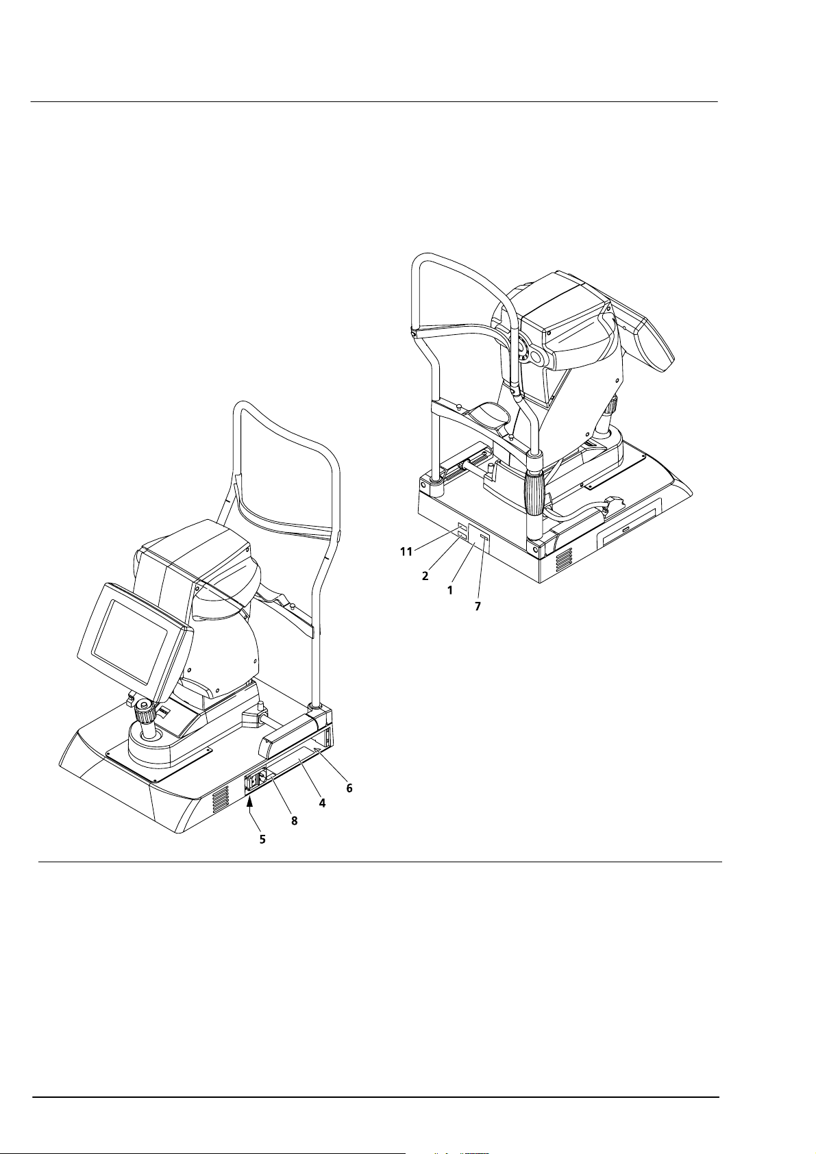
Warning and information labels on the device
The device casing carries the following warning and information labels.
Fig. 1 Warning and information labels on the device
000000-1322-734_GA_GB-US_120608
Page 19
Safety instructions
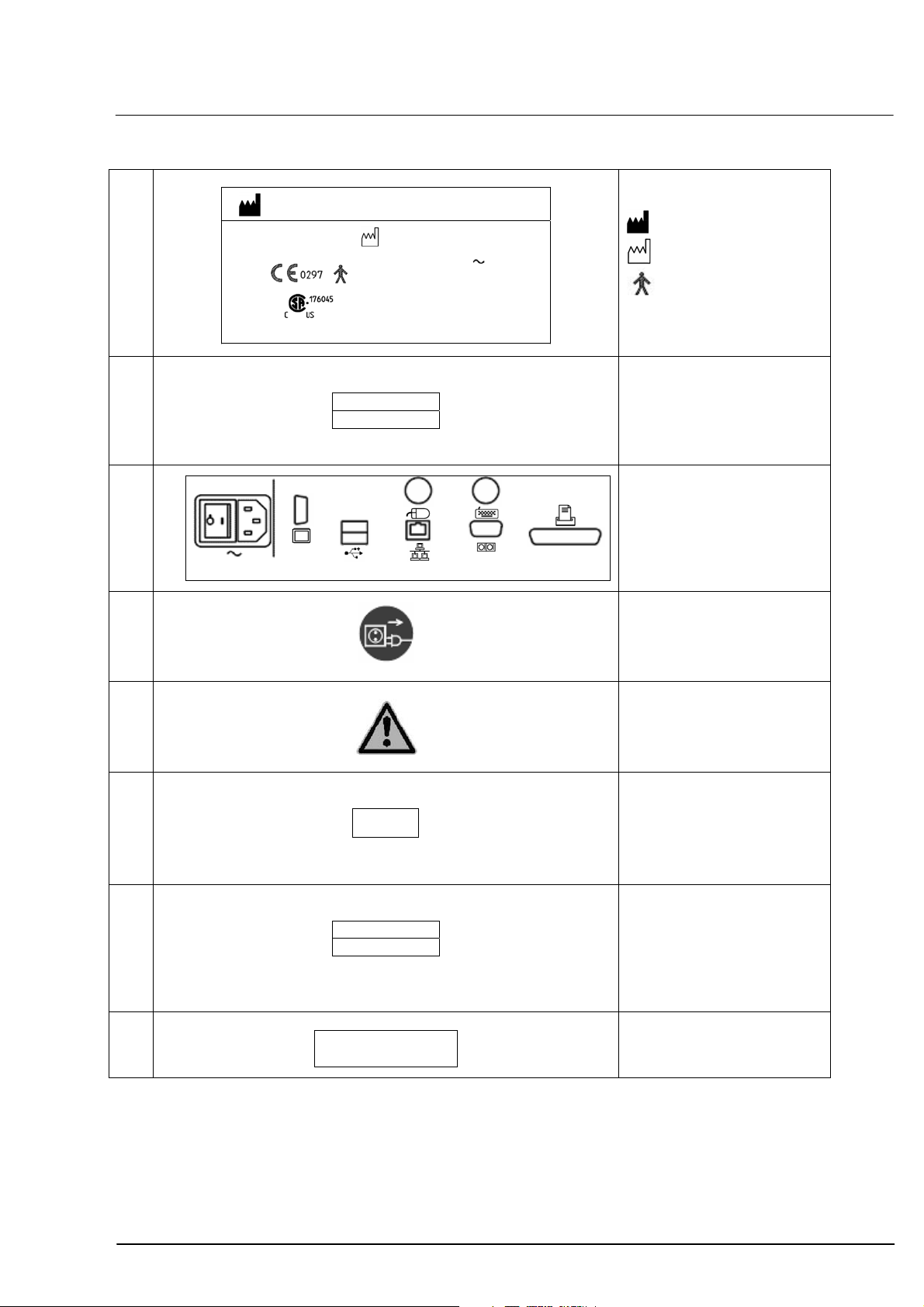
13
1
IOLMaster
000000-1322-734-01-DE-Vs02 MW IB
Carl Zeiss Meditec AG
07740 Jena, GERMANY
100…240 V
50/60 Hz
90 VA
IP20
2
REF 1322-734
SN XXXXXX
Type label
Manufacturer
Manufacturing date
Application parts
type B
as per IEC 60601
Identification plate IOLMaster
REF catalogue number/
part number
SN serial number
4
Connection panel
000000-1322-734-04-DE-Vs02
5
Warning
Disconnect the device from
the power supply before
servicing.
6
7
8
11
XX/XXXX
REF 1477-889
SN XXXXXX
Complies with 21 CFR
Subchapter J
000000-0000-007-US-Vs01
Warning label
Observe all safety notes and
information in this manual
"Manufactured" label
Manufacturing date
XX/XXXX = Month/Year
e.g. 06/2007
Identification plate
IOLMaster computer
REF catalogue number/
part number
SN serial number
Complies with 21 CFR
Subchapter J
000000-1322-734_GA_GB-US_120608
Page 20

14
Safety instructions
Customer’s safety obligations
The user is responsible for ensuring that:
the device is used in accordance with the instructions provided in this
manual.
deviations from the target refraction are precluded by proper
handling of the device:
– Patient must fixate correctly
– Device must be precisely focused for keratometry or anterior
chamber depth measurements.
– Biometry formulae must be properly used
– Only adjusted IOL constants may be used
the device is only used in a perfect operating condition without
functional impairment.
the user manual and all accompanying documents are maintained in
good condition and kept on or in the immediate vicinity of the
device.
only sufficiently trained and authorised personnel is permitted to
operate, maintain and repair the device.
all operating personnel receives regular instruction on all issues
concerning the device and its components, that such persons are
familiar with the user manual and, in particular, the safety
precautions
none of the warning signs on the system are removed or rendered
illegible.
the device is inspected daily according to
functions on page
each day no more than 20 axial length measurements are taken on
each patient’s eye.
a safety inspection is performed on the device each year (see
page
132), in order to guarantee its perfect operating condition.
128 before any patient measurements are taken.
Checking the measurement
000000-1322-734_GA_GB-US_120608
Page 21

Description
Intended use of the device
The device is to be used only for the measurement of axial length,
corneal radii, anterior chamber depth and optionally for the
determination of "white-to-white" of the human eye, as well as for the
calculation of the required intraocular lens. Responsibility for using the
device other than as intended lies with the user.
The device may only be used in combination with accessories delivered
by Carl Zeiss Meditec (see Section
Please consult Carl Zeiss Service regarding the use of other accessories.
Functional description
The IOLMaster is a combined biometry device for measurements on the
human eye required for the preoperative computation of intraocular
lens power.
It is capable of fast and precise consecutive measurement of the
following eye parameters in one session: axial length, corneal curvature,
anterior chamber depth and optionally "white-to-white". All
measurements are non-contact, providing excellent patient comfort.
Optional accessories on page 18).
15
The axial length measurement is based on a patented interference
optical method known as partial coherence interferometry (PCI). The
displayed results of the axial length measurements are compatible with
the ultrasonic immersion measurements of axial length via the use of an
internal, statistically verified calculation algorithm. The familiar formulae
for IOL calculation can thus be used.
However, the lens constants must be changed for use with the PCI
method. Please consult the scientific literature on this subject.
The corneal curvature is determined by measuring the distance between
reflected light images projected onto the cornea.
The anterior chamber depth is determined as the distance between the
optical sections of the crystalline lens and the cornea produced by
lateral slit illumination.
"White-to-white" is determined from the image of the iris.
The individual measurement procedures are automated, so that the
operator is only required to adjust the device to the patient’s eye and
initiate the measurement. For this reason the complex biometry of the
eye can be rapidly learnt with the IOLMaster, but should be practised
with the greatest of care and attention to detail.
Extensive integrated safety features (independent redundant hard and
software safety features) ensure maximum safety for both the patient
and operator when using the IOLMaster.
The control program for the computer in the device base runs under
Windows. A backlit LCD serves to observe the patient’s eye and display
000000-1322-734_GA_GB-US_120608
Page 22

16
Description
the readings. The device is controlled by the joystick and computer
keyboard with integrated touchpad.
Based on the readings, the program can make suggestions for the
choice of intraocular lens strengths. The latter are based on
internationally accepted calculation formulae. The Haigis, HofferQ,
Holladay, SRK
software.
®
1
II and SRK®/T formulae are implemented in the
The Haigis-L formula may be used to calculate IOLs after
LASIK/PRK/LASEK.
The refractive history or contact lens method may be used to correct the
measured corneal radii/refraction following refractive corneal surgery.
Selected phakic implants may be calculated by the "calculation of
phakic implants".
1
1
1
An IOL database is likewise implemented. Prior to calculation, the latter
must be filled with data for the desired lens.
On the basis of postoperative refraction results, the lens constants
entered into the calculation formulae may be optimised (personalised)
for each individual user.
1
Literature on the formulae (in case of specific questions please contact Carl Zeiss Meditec):
• Haigis:
http://www.augenklinik.uni-wuerzburg.de/uslab/ioltxt/haid.htm
• HofferQ:
HOFFER KJ: The Hoffer Q formula: A comparison of theoretic and regression
formulas. J Cataract Refract Surg, 19:700-712, 1993; ERRATA 20:677, 1994
• Holladay:
HOLLADAY JT, PRAGER TC, CHANDLER TY, MUSGROVE KH, LEWIS JW, RUIZ RS: A
three-part system for refining intraocular lens power calculations. J Cataract Refract
Surg, 14:17-24, 1988
• SRKII:
RETZLAFF J: A new intraocular lens calculation formula, Am Intra-Ocular Implant
Soc J 6:148-152, 1980
• SRK/T:
RETZLAFF J, SANDERS DR, KRAFF MC: Development of the SRK/T intraocular lens
implant power calculation formula. J Cataract Refract Surg 16 (3):333-340, 1990
• Haigis L:
HAIGIS W: Publication in preparation
• Correction of corneal radii/corneal refraction after corneal refractive surgery:
HOLLADAY JT: IOL calculations following RK. Refract Corneal Surg 5(3):203, 1989
HOFFER KJ: Intraocular lens power calculation for eyes after refractive keratotomy.
J Refract Surg 11:490:493, 1995
• Calculation of phakic implants:
vd HEIJDE GL, FECHNER PU, WORST JGF: Optische Konsequenzen der Implantation
einer negativen Intraokularlinse bei myopen Patienten. Klin MB1 Augenheilk
192:99-102, 1988
HOLLADAY JT: Refractive power calculations for intraocular lenses in the phakic eye.
Am J Ophthalmol 116:63-66, 1993
HAIGIS W: Biometry in complicated situations, 9th Conv. of DGII 1995, Rochels et al
(Hrsg.), Springer, 17-26, 1996
000000-1322-734_GA_GB-US_120608
Page 23
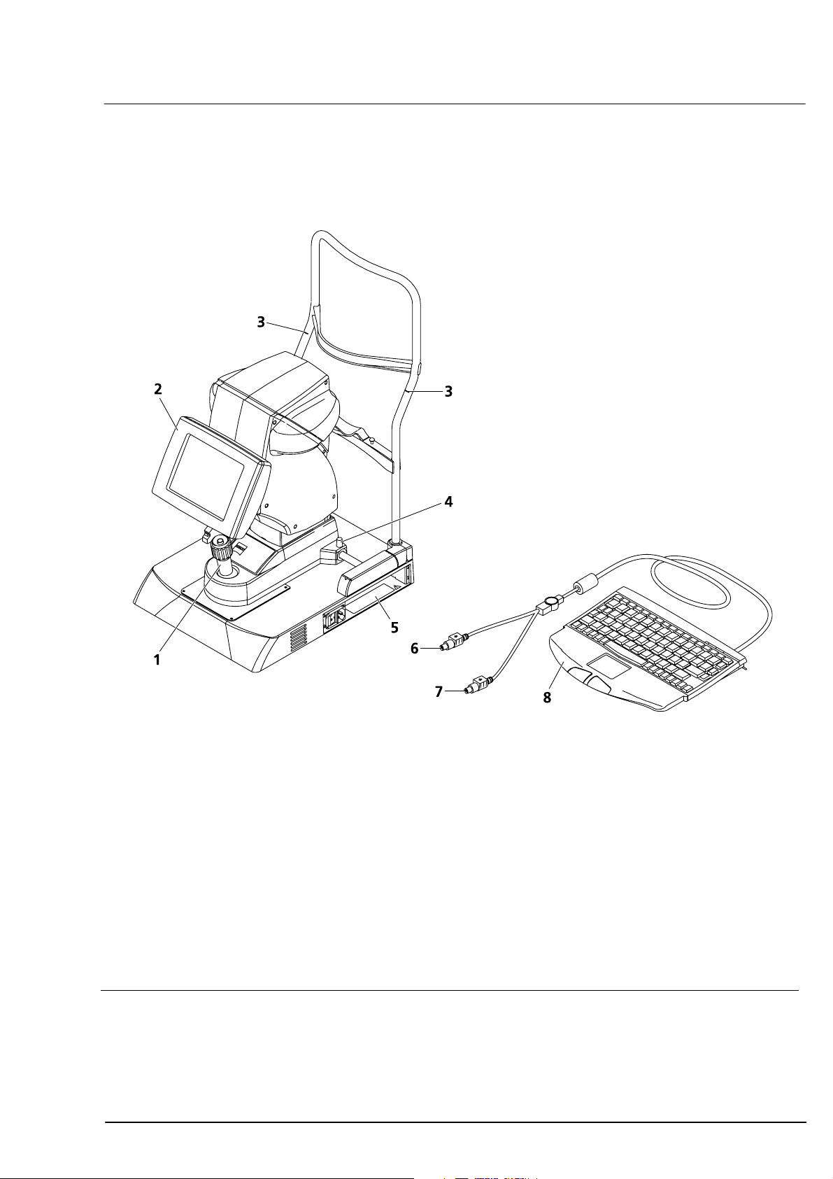
Overall view
Description
17
Joystick with release button
1
for adjusting the measuring device horizontally (X, Y) and vertically (Z, by turning)
Display
2
Patient eye alignment and display of results
Red eye level marks
3
Patient eye level needed for optimum measurement
Instrument lock knob
4
Connector panel (see also
5
Mouse connector (light green)
6
Keyboard connector (purple)
7
Keyboard (see also
8
Optional: Printer (not shown)
Fig. 2 View from doctor's side
000000-1322-734_GA_GB-US_120608
Fig. 9)
Fig. 10)
Page 24
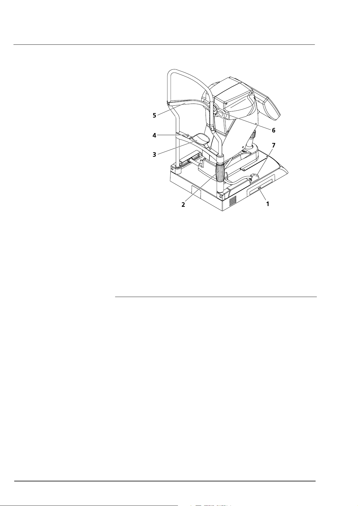
18
Description
DVD drive/CD-RW drive
1
for data storage and software installation
Adjustment of headrest
2
Patient chin rest
3
Holding pins for paper pads
4
also used to mount alignment aid (test eye)
Patient forehead rest
5
Aperture for semiconductor diode laser (MMLD)
6
Device control connector
7
Fig. 3 View from patient’s side
Optional accessories
Instrument table IT 3L
Holding bar for securing the IOLMaster on the instrument table
Printer
Keyboard support
Narrow holding bracket for securing the IOLMaster on the keyboard
support
Paper pads for patient chinrest
Power isolation transformer for connection of external accessory units
Network isolator
Software option A plus
Software option B
Connecting cable for coupling with PC
000000-1322-734_GA_GB-US_120608
Page 25
Description
2
2
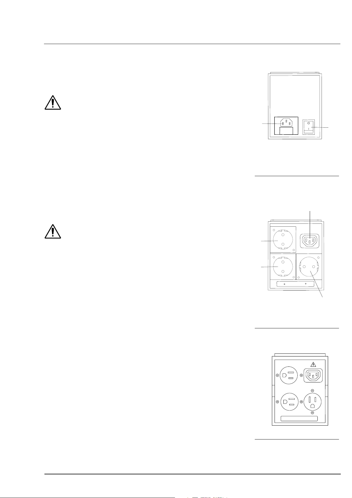
Power isolation transformer for external devices
Warning
Always connect all peripheral devices, printers and monitors to the
power isolation transformer.
No components other than those prescribed for the system may be
connected to the power isolation transformer or instrument table. Noncompliance represents a violation of the regulations for use of medical
devices under DIN EN 60601-1-1.
Likewise excepted are laser printers, as their rated supply voltage
usually exceeds the permissible connected load of the power isolation
transformer. Position the laser printer outside the patient’s range
(1.5 m from the patient’s seat at the device).
If the Carl Zeiss IT 3L instrument table is used, the power isolation
transformer may be mounted to the underside of the tabletop. It may
be secured elsewhere, but not placed on the floor.
1
Power cable connector with
1
fuses
Power switch
Fig. 4 Power isolation trans-
former, input side
1
19
2
Warning
The IOLMaster should never be operated via the power isolation
transformer!
The power isolation transformer is not a constituent part of the
IOLMaster.
2
2
Instrument connector
1
Power junction connector
Fig. 5 Power isolation trans-
former, output side 230 V
2
Fig. 6 Power isolation trans-
former, output side 120 V
000000-1322-734_GA_GB-US_120608
Page 26
20
Description
Setting up the device for use
The device must be set up and commissioned by authorised
representatives of Carl Zeiss; the latter will also instruct the users on
operation of the device.
In general, Carl Zeiss Service will perform the following operations.
Installation
Remove and unpack box containing accessories.
Carefully remove the device from the box (The device should not be
lifted or carried by the measuring head!).
Removing shipping braces:
– Loosen device lock knob (4,
– Basic setup: Turn joystick clockwise (one turn) to move the device
upward and pull out the red plate underneath the base axis
(patient side).
– Remove red pads from the wheel housing of the device base.
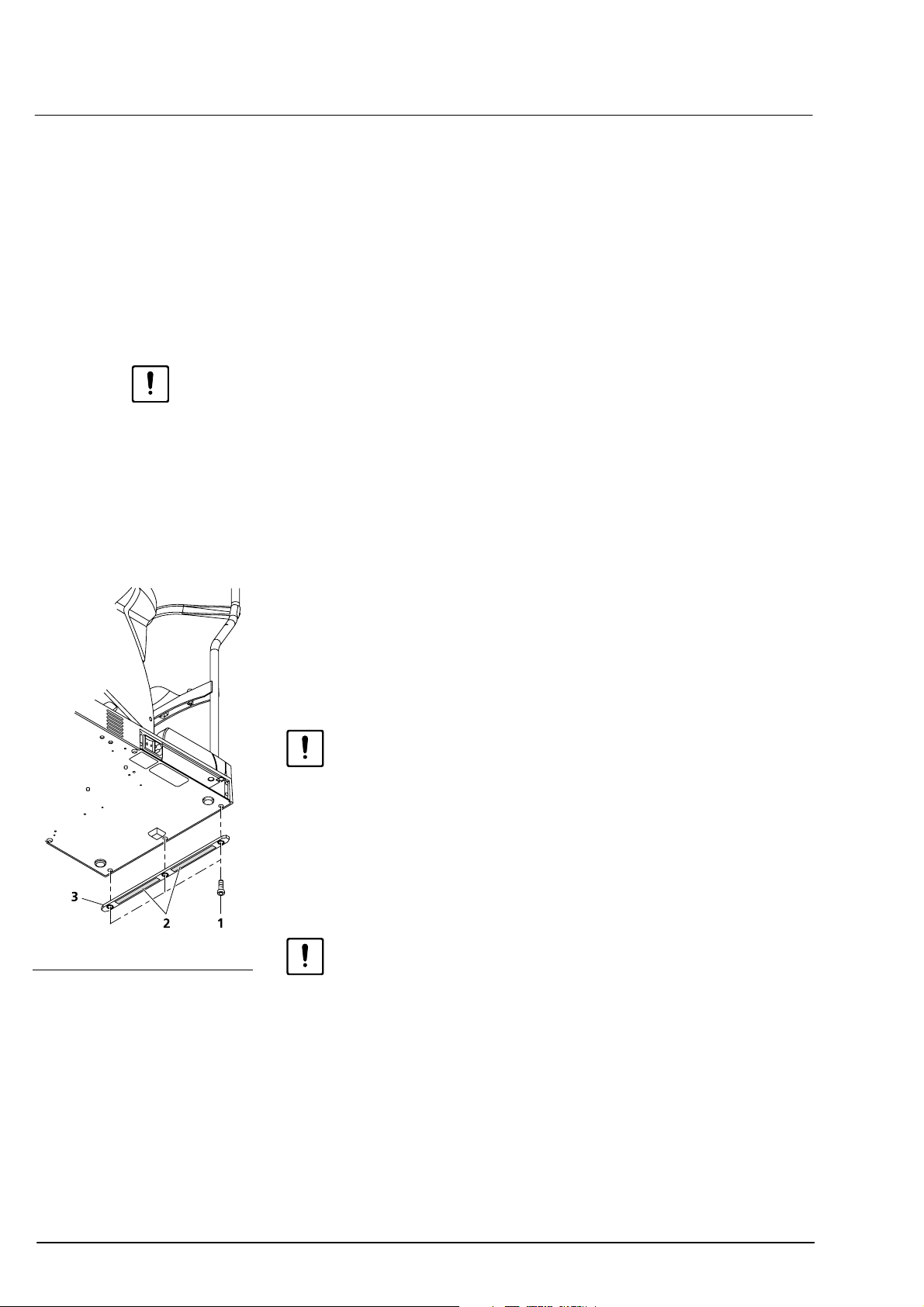
Fig. 2)
Fig. 7 Mounting holding bracket
Secure device with holding bracket
The IOLMaster can be permanently secured with the aid of a holding
bracket (3, Fig. 7) Holding brackets with two different widths are
available:
– 7 mm holding bracket for securing to the instrument table
– 5.5 mm holding bracket for securing to the keyboard support
Caution
The two holding brackets are mounted in the same way. Make sure you
use the correct holding bracket.
Do not lift or carry the device by the measuring head!
• Tilt the IOLMaster to one side so that it rests on the patient head
support.
• Remove the three hexagon socket (Allen) screws (SW3) (1, Fig. 7).
The screws may be very difficult to loosen.
Caution
Do not remove any other screws on the base plate! Damage may
otherwise be caused to the device.
• Attach the holding bracket with adhesive strips (2,
outwards.
• Secure the holding bracket with the three hexagon socket screws. Do
not yet remove the protective film from the adhesive strips.
• Set the device upright and place it in the desired position.
• Now lift/tilt the device slightly and remove the protective film
Fig. 7).
(2,
• Bring the device carefully into the proposed position. The adhesive
strips will hold immediately. The device can no longer be shifted once
it has been brought into position!
Fig. 7) facing
000000-1322-734_GA_GB-US_120608
Page 27
Description
21
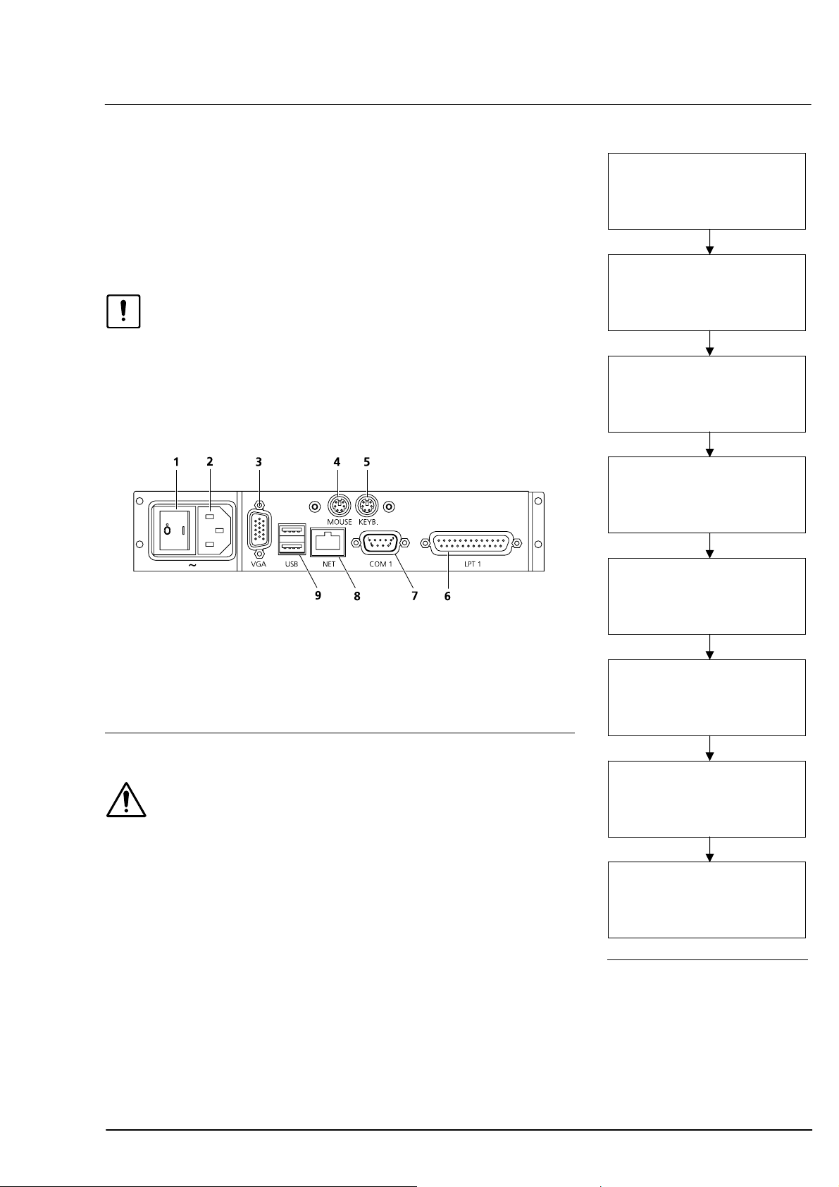
Electrical connection
• Connect mouse and keyboard.
• Optional: Plug in and secure monitor (VGA) and interconnecting
cable (NET/COM 1)!
• Connect power cable.
• Install printer as described in
Caution
Use only printers recommended by Carl Zeiss Meditec! Only one printer
may be installed. De-install all surplus printer drivers using menu
Setup - Printer.
Prior to using older printers, please consult Carl Zeiss Meditec whether
the printer is approved for use with the IOLMaster.
Power switch
1
Power supply plug (~)
2
Monitor port (VGA)
3
Mouse port (MOUSE)
4
Keyboard port (KEYB)
5
Ã
Fig. 8.
6
7
8
9
Printer port (LPT1)
External PC port (COM 1)
Network connector (NET)
USB interface (USB)
Ã
Ã
Ã
Ã
Install printer according to
manufacturer’s user manual.
Do not connect it to the
IOLMaster yet!
Start IOLMaster and wait until
New patient is displayed.
Switch on printer and connect it
to IOLMaster (USB/LPT 1).
The Windows installation routine
will be displayed.
Select option "No, not at this
time" and confirm with NEXT.
Insert installation CD for printer
driver and wait for language
selection to appear in selection
window.
Select appropriate language and
confirm with NEXT.
Fig. 9 Connection panel
Warning
Ã
If connecting external devices, e.g. an external PC, to the connectors
or an external monitor to the VGA connector, the operator must
ensure to meet the safety requirements as per DIN EN 60601-1-1
(medical electrical systems)!
A network isolator must be inserted for connection to an external
network (NET).
The IOLMaster may only be connected to private networks which are
protected from public networks (Internet) by firewalls conforming to
the latest technical standards!
When the device is turned on at the power switch, it will run through
an internal test. Once this has been completed successfully, the device
may be operated. Certain operating parameters are factory set and may
be changed in the Setup menu (see page 34).
000000-1322-734_GA_GB-US_120608
If a dialog box for the installation
of additional printer software is
displayed, close this box without
installing another printer.
The windows installation routine
will confirm that installation of
the selected printer is finished.
Exit with
Fig. 8 Installing the printer
FINISH.
Page 28
22
Operation
General notes on control
The operating system of the device's control computer works in the
background. For safety reasons, it is not accessible to the user.
Warning
All attempts to manipulate the operating system are strictly prohibited!
In particular, deactivation of the Windows firewall is not permitted!
Windows operating conventions apply analogously to the user interface
of the IOLMaster software. This relates to working with a
mouse/touchpad, the use of icons, working with dialog boxes and
menus, confirmation by double-click, etc.
Note
The system does not support all key combinations of Windows.
The special Windows keys that exist on some keyboards are
ineffective.
The software uses only a few forced processes. The user may switch
freely between the individual modes. For rational working the user is
urgently advised to observe the sequence of measurements described
from page
In rare cases, Windows error messages may appear on the LC display.
This might be the case, for instance, if the program running is affected
(mostly by external disturbances).
Multiple safety mechanisms in the instrument’s hardware and software
ensure that there is no risk of injury.
Caution
If warning messages appear frequently, the device should be taken out
of service and labelled as such. Then call Carl Zeiss Service.
The device does not support the submission of automatically generated
problem reports to Microsoft!
The device may be operated by:
using the icons (by cursor, touchpad) or
keyboard or
menus.
53 onwards.
Measurements are initiated by pressing the button on the joystick.
000000-1322-734_GA_GB-US_120608
Page 29
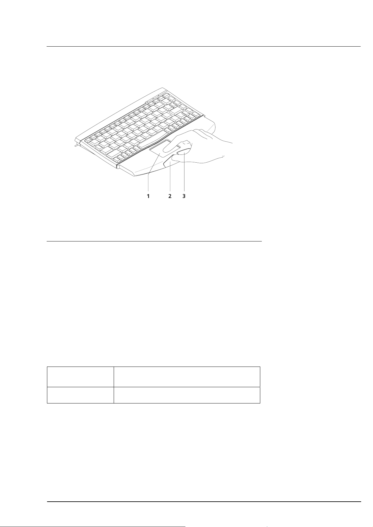
Operation by touchpad and keyboard
Touchpad
1
Left button
2
Right button
3
Operation
23
Fig. 10 Touchpad control
Move the cursor by touching the touchpad with your finger and
moving it as desired.
Single and double clicks are possible by tapping a finger on the
touchpad or pressing the left button.
To drag the cursor, hold the left mouse button depressed while
moving the finger across the touchpad.
The right button is only functional for:
– resetting the zoom function (page
101)
– continuous positioning of the measuring cursor while dragging
(see page
Single click Selection of menu, textbox or entry.
Double click OK, confirmation of actions.
104)
Operation of Windows buttons or icons
In addition to program control via touchpad you may also activate
certain menus by pressing individual keys or key combinations (see
Menu overview on page 28 and Overview of buttons and shortcut keys
on page 25 ff.).
000000-1322-734_GA_GB-US_120608
Page 30
24
Operation
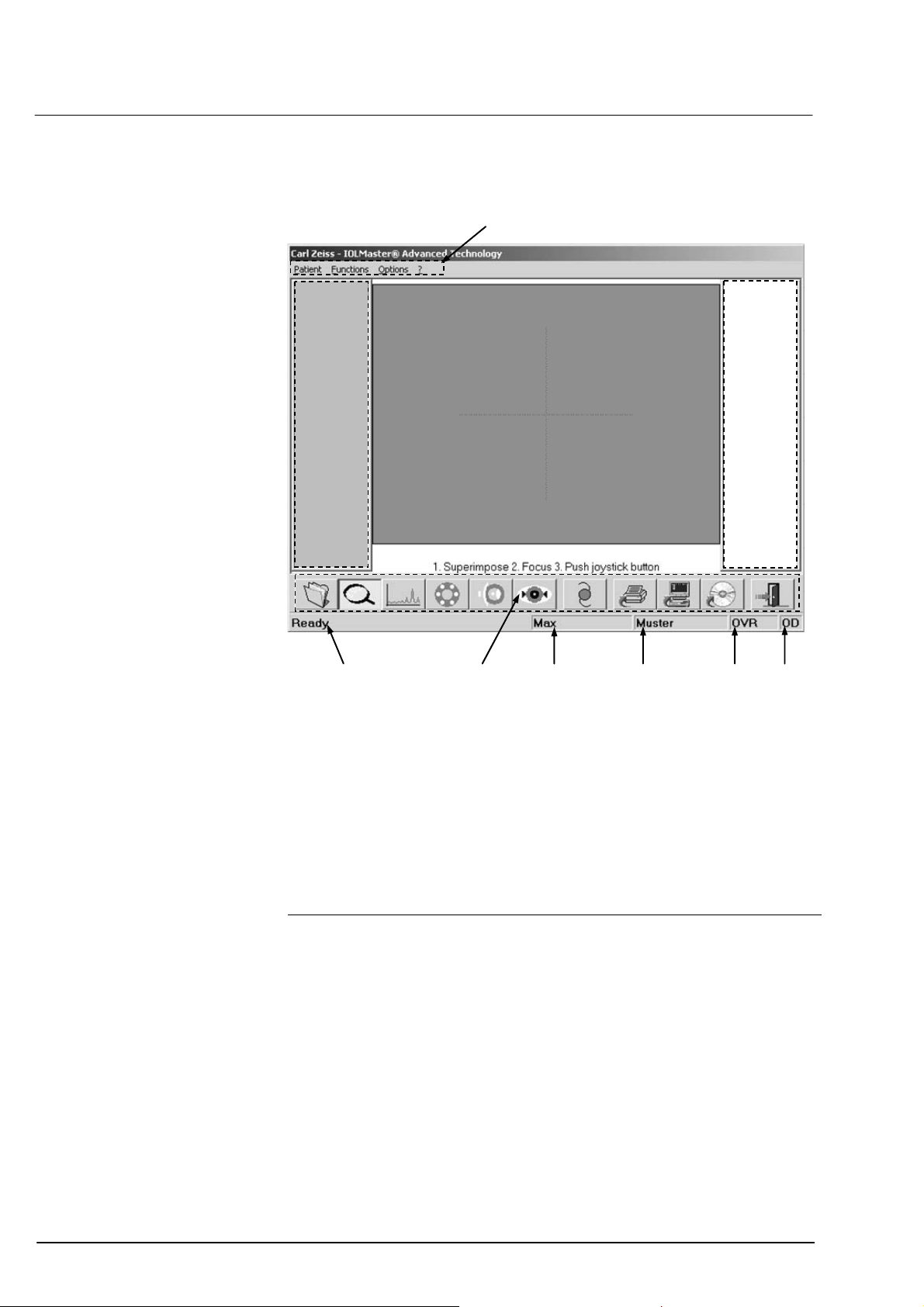
Screen layout
1
2
10
Menu bar
1
Display field for measurements of right eye
2
Display field for video images
3
Display field for measurements of left eye
4
Eye
5
Mode (additionally in ALM mode: number of measurements)
6
Last name
7
First name
8
Icons
9
System messages/progress bar
10
98 7 6 5
3
4
Fig. 11 Screen layout
000000-1322-734_GA_GB-US_120608
Page 31

Operation
Overview of buttons and shortcut keys
Icon Key Function Explanations
25
<N>
<O>
<A>
<K>
<D>
<W>
<I>
<P>
Activates patient data
entry screen.
Activates overview
mode and light spots.
Activates axial length
measurement mode.
Activates keratometer
(corneal curvature
measurement) mode.
Activates anterior
chamber depth
measurement mode.
Activates WTW
determination (optional)
Activates IOL
calculation.
Prints results obtained
hitherto
For new patients, input of
patient data is essential
Functions in all modes and
for every measurement
WTW = white-to-white
Calculation already possible
after measurement of one
eye
Warning
Ã
If connecting external devices, e.g.
an external PC, monitor or an
external network, the operator must
ensure the safety requirements are
met as per DIN EN 60601-1-1
(medical electrical systems)!
<S>
<X>
<E>
Sends data Requirement: A suitable
computer must be connected
to the serial interface or the
IOLMaster must be
connected to a network*
Transfers data to CDRW or USB flash drive
Requirement: CD-RW has
been inserted into the drive
or USB flash drive is
connected to USB port.
Exits IOLMaster
software and Windows
and shuts down the
device
Functions in all modes and
for every measurement;
in case of damage: pull out
power supply plug
immediately!
000000-1322-734_GA_GB-US_120608
Page 32

26
Operation
Key functions without icons
Key Function Notes
Space bar
Joystick
button
<DEL>
<M>
<CTRL> + <Z>
<CTRL> + <P>
Cyclic change of modes:
ALM, KER, ACD, WTW
Program continuation/
Activates measurement
Deletes the selected ALM
or KER measurement
from the list
Briefly inactivates
"automatic" function
Restores the last
measurement
Effective in ALM mode:
prints the image of the
selected graph;
effective in WTW mode:
prints the selected image
of the eye.
ALM o KER o ACD o WTW
…
In overview mode: change to
ALM mode
In ALM, KER, ACD and WTW
mode
Only in ALM, KER and WTW
mode with acknowledgment
Briefly interrupts adjustment
aid automatic function in KER
mode
Effective only in KER, ACD and
WTW mode
ALM: one graph only
WTW: right and left eye
000000-1322-734_GA_GB-US_120608
Page 33

Operation
Summary of result displays
Display Meaning Notes
rd
axial length
3
measurement (22.55 mm)
selected.
Displays measurement curve of
this measurement.
27
SNR: 6.4
Unreliable value
SNR displays YELLOW
(SNR = signal-to-noise
ratio)
Measuring error
SNR display RED
Result has been
manipulated.
SNR display and SNR
(signal-to-noise ratio)
beside signal curve
Measuring cursor is
positioned above signal
peak
"Borderline SNR" (uncertain
value) appears above graph.
Result should be examined by
the user for validity.
"Error!" appears above axial
length graph.
* remains displayed even if
manipulation has been
undone!
Values for the peak below the
measuring cursor.
000000-1322-734_GA_GB-US_120608
Page 34

28
Operation
Menu overview
Patient
New
Opens dialog box for
entry of new patient;
entry compulsory
Erase
Deletes patient data
Rename
Renames patient data
Query waiting room...
Export
Exports patient data to
CD-RW
Send
Sends data via interface
(serial, DICOM
oder EMR)
Remark
Edits a comment
Print
Prints measurement table
Print current graph
Prints the selected graph
in ALM mode
Print current current
WTW images
Prints the current
images in WTW mode
Print previev
Displays print preview
-
Functions
Undo
Undoes last KER/VKT
value
Recover
Recovers deleted ALM
readings
Overview
Activates overview mode
Axial length
measurement
Activates ALM mode
Corneal curvature
measurement
Activates KER mode
Anterior chamber depth
measurement
Activates ACD
measurement
White-to-white
determination
Activates WTW
determination
IOL Calculation
ALM Settings
Accessible in ALM mode
only
Phakic
Aphakic
Pseudophakic silicon
Pseudophakic memory
Pseudophakic PMMA
Pseudophakic acrylate
Silicon-filled eye
Silicon-filled eye,
aphakic
silicon-filled eye,
pseudophakic
Phakic IOL PMMA
(0.2 mm)
Primary piggy-back
silicon (SLM 2)
Primary piggy-back
hydrophobic acrylate
Options
Test eye
Activates/deactivates
measurement mode for
test eye
Lens database
Enters and edits user and
IOL data
Setup
Adjusts various settings
Date/time
Sets system clock
Program settings
Adjusts program/export/
network/view
settings
User management/ User
manager
Regional settings
Windows routine
Printer
Opens system folder
SW option
Installs/de-installs
software options
Update
Installs software update
Carl Zeiss Meditec
Teleservice
Opens remote
maintenance dialog box
Service
Only for service
(password-protected)
Printer setup
Selects printer options
Logout
Logs current user off and
opens login window
Exit
Exits application and
Windows
?
About IOLMaster
Displays and prints
information on program
version
000000-1322-734_GA_GB-US_120608
Page 35

Operation
Options menu
Test eye
The calibration of the device can be checked with this function (see
Section
Lens database
Since the device may be used for the preparation of eye surgery by a
number of surgeons, surgeon-specific records may be created. This is
performed using the Lens database in the Options menu.
Checking the measurement functions on page 128).
29
• Click on
box for entering surgeon-specific data will appear.
Fig. 13 Please enter password dialog box
Note
LENS DATABASE in the Options pull-down menu. The dialog
When the device is delivered, the Lens database only contains
the administrator without any password specifications
Fig. 12 Options menu
Only the administrator is entitled to add or delete users and edit their
databases.
Note
Individual users may edit their databases only if password
protection has been set. If no password protection was set, the
databases are accessible to all users!
If Change password is checked, the administrator may assign himself a
password in this dialog box.
• Type in the password in the New password and Confirmation text
boxes.
• Confirm your entry with
000000-1322-734_GA_GB-US_120608
OK.
Page 36

30
Operation
• To create a new lens database the administrator must open his or her
own database by selecting Administrator in the Name list box.
A dialog box appears, in which new users may be added.
Fig. 14 Lens database - Administrator dialog box
• Type in the name of the new user.
• If several users share the device it is recommended specifying a
password each, which must be repeated in the Confirmation text
box.
• You can
existing users, you can
• If you wish to delete user data from the database, click on the
ADD the new users you have thus entered. In the case of
SET any changes in the name or password.
ERASE
button after having selected the name in the left window.
• Click
OK to confirm your user entries. The new user is now registered
in the database.
• For the entry of lens data, refer to
Filling the IOL database (page 75 f.).
Note
Should a user forget his or her password, the administrator may
assign a new password. To do this, the logged-on administrator
must highlight the user in the left box and assign a new password
with the
SET command button.
Caution
A forgotten administrator password can only be recovered by
Carl Zeiss Service!
000000-1322-734_GA_GB-US_120608
Page 37

Data store
Backup (creating a backup copy)
Operation
31
With the
used for the optimisation of IOL constants together with the IOL data of
all surgeons and corresponding lenses used for the calculation.
Warning
A compressed and password-protected file is created in the CD-RW. Do
not attempt to read or manipulate this file using other programs!
The respective measurement readings are saved together with the
patient’s personal data, regardless of the set deletion date.
The backup process also includes the tables used for IOL constant
optimisation (assignment of surgeon/lens/patient/eye/post-operative
data). Additionally, the IOL constants currently used for calculation will
be saved for all surgeons.
BACKUP function, you can save to a CD-RW the patient data
Note
If you wish to export data to a CD-RW, you must insert a
formatted CD-RW into the drive. The CD-RW must be formatted
elsewhere (e.g. office PC) in UDF format. Only the Nero InCD is
suitable for formatting in UDF format. Alternatively, use one of
the formatted CD-RWs as supplied.
Note
In this way, all critical patient and IOL data can be saved together
with the data required for lens optimization. Individual values of
axial length, corneal curvature/refractive power, anterior chamber
depth, WTW are not saved and may get lost, e.g. in the case of a
hard disk fault.
Follow this procedure to create a backup copy:
• In the Lens Database activate Administrator.
• Click the
• Insert a UDF-formatted CD-RW into the drive.
• Confirm with
• It may be necessary to delete existing data on the CD-RW (conform
with
The data will now be copied to the CD-RW. A progress bar will show
the status of the copying process.
• Finally, you will be informed that data backup was successful.
BACKUP command button to initiate the backup process.
OK.
YES). Answering with NO will abort the backup process.
000000-1322-734_GA_GB-US_120608
Page 38

32
Operation
Restore
By using the
RW to the IOLMaster. Follow this procedure to restore saved data:
• In the Lens Database activate Administrator.
• Click RESTORE.
•
Insert the CD-RW with the latest backup copy; confirm with OK.
• Confirm with YES that all surgeon data currently stored on the
IOLMaster is to be copied, together with the respective IOL data and
patient data available for optimising the IOL constants.
Database data will now be copied from the CD-RW to the IOLMaster.
A progress bar will show the status of the copying process.
• Finally, the program will inform you if the restore action was a
success.
Note
After backed up data has been restored, the Lens Database will
reflect the status at the time of backup. All newly registered
patients since this time will be irretrievably lost!
Import
The Import function permits IOL data (name and respective IOL
constants) to be transferred back to the IOLMaster from a database
saved to CD-RW or USB flash drive (Version 1.1 or later). Imported data
may be assigned to one or several surgeons.
Prior to import, download the available IOL data from the Internet.
RESTORE function you can retransfer saved data from a CD-
Copy the IOL data to a storage medium
Note
Download IOL data using a PC connected to the Internet and a
CD-(RW-) recorder or USB flash drive
Caution
Do not use a network-connected IOLMaster for the download!
• Log into www.meditec.zeiss.com/iolmaster.
• Select Optimized lens constants from More information.
• Follow the prompts now appearing on the screen.
• Save the file (do not select Open!) on the desired storage medium.
• Do not extract the ZIP file!
.
000000-1322-734_GA_GB-US_120608
Page 39

Operation
Importing IOL data from the storage medium to the IOLMaster
• In the Lens Database activate Administrator.
• Click on the
• Insert the CD-RW or USB flash drive with the database to be
imported and confirm with
IMPORT button.
OK.
33
Fig. 15 Import of lens constant data dialog box
• Choose the desired lenses; select several lenses with <CTRL> + cursor
+ click (selected lenses appear highlighted in blue).
• Choose the surgeon (one or more) with
<CTRL> + cursor + click
(selected surgeons appear highlighted in blue); if not already existent,
the desired surgeons must be created beforehand.
• Accept with
>>. A progress bar will show the status of the copying
process. The selected lens data will be added to the selected
surgeons.
• Close the dialog box with
000000-1322-734_GA_GB-US_120608
OK.
Page 40

34
Fig. 16 Setup submenu
Operation
Setup
The Setup submenu contains the following entries:
Date/Time
Opens the Windows routine for setting the system clock.
Program settings/Program
– Language: IOLMaster dialogs in German, English or other
languages (change requires system restart).
– Display of visual acuity: Decimal or Snellen. Entry of visual acuity
in Patient data dialog box.
– Database: Storage time of datasets (5 ... 365 days). All figures
between 5 and 365 are possible. 365 days are set at the time of
delivery. Data records can be identified or sorted by Name, first
name, … or by ID Number.
Caution
Please note that when switching from Name, first name… mode to
ID Number all data records without an ID Number will not be listed
(entry of an ID is not essential). This also applies analogously to
switching from ID Number to Name, first name… if a name was not
previously entered.
000000-1322-734_GA_GB-US_120608
Page 41

Operation
– Keratometer
Display: For displaying during IOL calculation, the specification
may be as a Radius or Corneal K's or - Cylinder or + Cylinder.
Refractive index: Entry of equivalent refractive index for
conversion of corneal radii to corneal K’s. Enter the refractive
index implemented on your keratometer (refer to respective user
manual).
– Adjustment aid Keratometer / Anterior chamber depth
Adjustment aid KER: If the
Keratometer, a traffic-light display will appear on measurement of
the corneal curvature. When the optimum measurement position
for the patient has been reached, the traffic light will change from
red to yellow to green. If the
upon pressing the joystick knob three measurements will be
automatically and consecutively triggered after the best-possible
setting for the patient has been made and the traffic light has
changed to green.
Adjustment aid ACD: If the
anterior chamber depth (ACD), a traffic-light display will appear
on measurement of the ACD. When the optimum measurement
position for the patient has been reached, the traffic light will
change from red to yellow to green. If the
activated, upon pressing the joystick knob the measurement will
be automatically triggered after the best-possible setting for the
patient has been made and the traffic light has changed to green.
ADJUSTMENT AID is activated for the
AUTOMATIC KER is also activated,
ADJUSTMENT AID is activated for the
AUTOMATIC ACD is also
35
Fig. 17 Dialog box Program settings/Program - Keratometer and Keratometer/
Anterior chamber depth adjustment aid
– Printing of IOL calculation data
Choose whether you wish to have the calculated IOL data of both
eyes printed on a single page or only one eye per page. In
addition, in this field you may enter the name of the clinic to
appear on the printout of the IOL calculation.
Select
000000-1322-734_GA_GB-US_120608
EMMETROPY IOL if desired.
Page 42

36
Operation
Program settings/Export (requires Option A plus)
Select export settings. Under Identification select the patient
identification categories, under Measurement Values the values to be
exported, and under File output the corresponding output path. The
file name can be freely selected. By convention, the file name may
not contain the separators ": / \ ? * ". Data will be saved in (*.csv)
text format (separator selectable) and may be read using other
applications (e.g. MS Excel):
Fig. 18 Program settings/Export dialog box
Program settings/Network
Warning
Configuration and changes to the network settings should only be
carried out by an experienced network administrator.
– Network information
Here you will find all the key network information such as
Computer Name, Working Group, IP and MAC address. Use
the
CHANGE NETWORK SETTINGS BUTTON to configure the
IP address.
000000-1322-734_GA_GB-US_120608
Page 43

Operation
– Serial Port:
Use the Serial Port to exchange data with another PC, or the
practice administration system installed on it.
Choose old, if the connected office management system only
allows import of data of interface software versions 1.01 to 2.02
(patient data, measured values).
Choose new (with IOL calc. table) (requires option A plus), if
the connected office management system can import all offered
data according to interface software version 3.0 and higher.
COM speed provides a choice of standard transfer rates in Baud.
– DICOM (requires Option N):
Activate the option box under DICOM (Digital Imaging and
Communications in Medicine) to exchange DICOM-standard data
with the information system of your hospital. For example, with
the help of the DICOM Modality Worklist you can automatically
transfer jobs, including all relevant patient data, from the
hospital's information system to the IOLMaster.
You need to configure the Network Broker to be able to use this
option. Access the Network Broker Configuration Tool by clicking
BROKER CONFIGURATION button.
the
37
Warning
Configuration and changes to the network settings should only
be carried out by an experienced network administrator.
– EMR (requires Option N)
If you activate the option button EMR (Electronic Medical
Record), you can exchange data with the EMR system of your
clinic or practice.
To do this, the IP address, the port of the EMR server, the
Application Entity Title IOLMaster (free choice of device name
for the IOLMaster, but must be unique within the network) and
the Application Entity Title EMR (this name must correspond
to the one given in the EMR system) must be entered in the
relevant text boxes.
000000-1322-734_GA_GB-US_120608
Page 44

38
Operation
Program settings/View
Depending on how your EMR or DICOM system is configured, you can
adjust the display of the patient measurements in the 2nd level of the
patient tree (patient manager list in database field).
Select Accession No. + Date if your system issues a process number.
Select Requested ProcedureID + Date if your system uses the
examination method-assigned IDs. Otherwise select the Date option.
Program settings/User management
– System login
IOLMaster and the patient database can be protected by means of
a password (acc. to HIPAA). For this purpose, activate the option
Operator login with password. A password must contain at
least one character.
Fig. 19 Program settings/User management dialog box
Note
The option
together with password protection, should not be activated until
further users (see below) have been registered and their
passwords entered.
If you change the Admin password, you are advised to note
down the new password, e.g. in the device record book. The user
administration system cannot be accessed without the
Administrator password!
If the password is lost, a number code will be displayed after three
unsuccessful attempts. This number code will enable service
personnel to reset the device.
OPERATOR LOGIN WITH PASSWORD and screen saver,
000000-1322-734_GA_GB-US_120608
Page 45

Operation
As soon as you have confirmed the new program settings with OK, a
login dialog will appear. From now on the IOLMaster can only be used
by logging in with password. The default setting is user Admin with the
password 0000 (4x zero) in the User manager. To change the
password, select the option Change password, enter your user name
and old password and confirm with
Fig. 20 Login dialog box
OK.
39
In addition, a screen saver with a freely adjustable interval can be
activated. The screen saver appears if the IOLMaster has been inactive
for longer than the set interval. This prevents unauthorised access to
protected patient data.
PASSWORD PROTECTION option offers added protection. If this is
The
activated, you will only be able to work with the IOLMaster and its
database after logging on again with the password.
Fig. 21 Program settings/User management dialog box
000000-1322-734_GA_GB-US_120608
Page 46

40
Operation
– User Manager
Click on the
hand side of the User Management in the User Manager permits
further users to be registered (with the
password to be specified (
deleted (
USER MANAGER button. The dialog box on the left-
NEW button), their
CHANGE PASSWORD) or users to be
DELETE).
Fig. 22 Program settings/User management - User manager dialog box
Each user may be a member of one or more user groups. For this
purpose, highlight the respective user. The user groups to which this
user belongs are shown in the right-hand window Membership.
The user can be assigned to one of the following user groups by clicking
on
ADD:
– The Administrator has unrestricted access rights to User
management, the Lens database (see page
29) and the Setup
menu.
– The Surgeon only has an access right to the respective tab in the
Lens database. This tab is created automatically when the user
account is established in the User Manager.
– The Assistant has no right of access to the Lens database.
000000-1322-734_GA_GB-US_120608
Page 47

Operation
All user groups may enter/rename patient data and perform
measurements / calculate IOLs.
Users who are not members of any of the above user groups may work
on the IOLMaster in the usual way, but they may not change any of the
system settings.
To remove a user from a user group, highlight the name and click on
REMOVE.
Note
The rights of the Surgeon and Assistant user groups in the User
Group Administration may be extended to include access to the
IOLMaster Setup menu and the deletion of patient data.
Regional settings
Opens the Windows routine for regional settings.
Printer
Opens the Windows printer folder. This function is only needed for:
– showing the printer queue
– displaying the properties of the installed printer. Here you will find
advice on operating and maintaining the printer
– removing a printer that is no longer required (see also page
21).
41
SW option
Installing or de-installing a software option
Update
To install a new software version from a CD:
– Insert an update CD into the drive.
– Click on Update to start the software update installation routine.
– Follow the instructions on the screen up to the restart prompt.
– Remove update CD from the drive. If the IOLMaster reappears in
New patient mode after restarting, the installation of the
software update has been completed.
000000-1322-734_GA_GB-US_120608
Page 48

42
Operation
Carl Ceiss Meditec Teleservice (requires Option T)
Used for remote maintenance of IOLMaster by Carl Zeiss Service (see
section Remote maintenance (optional), page 127).
Service
For servicing purposes and password-protected.
Warning
Unauthorised persons may under no circumstances use the service
password. The safety warranty for the medical device will otherwise
become invalid!
000000-1322-734_GA_GB-US_120608
Page 49

Operation
Network Broker configuration (optional)
Note
The Network Broker configuration described on the following
pages should only be performed by experienced network
administrators.
43
Fig. 23 Network Broker Configuration Tool, start screen
x Start the Network Broker Configuration Tool by clicking on the
BROKER CONFIGURATION button in the Program setting/Network
menu (see page
37).
x Select the desired language for the configuration instructions and
click
CONTINUE.
Note
Click the
obtain assistance at each configuration step. Use the
HELP button in all of the configuration tool windows to
CONTINUE
and BACK buttons to navigate between the individual
configuration steps. Click
dialog
.
CANCEL to cancel the configuration
000000-1322-734_GA_GB-US_120608
Page 50

44
Operation
Fig. 24 Network Broker Configuration Tool, step 1
You can create a new configuration using the Network Broker
Configuration Tool or edit an existing configuration. It is only possible
to edit an existing configuration if such a configuration has already been
created for the configuration tool to call up. When adapting an existing
configuration a backup of the old configuration is automatically made,
meaning that configuration can be cancelled at any time without loss of
data.
• Once you have selected a task, click on
CONTINUE.
000000-1322-734_GA_GB-US_120608
Page 51

Operation
45
Fig. 25 Network Broker Configuration Tool, step 2
• Select the IOLMaster from the list of devices.
• Activate the SOCKET COMMUNICATION option.
(The
FEP COMMUNICATION option is not permitted.)
• Click on
CONTINUE.
000000-1322-734_GA_GB-US_120608
Page 52

46
Operation
Fig. 26 Network Broker Configuration Tool, step 3
• Enter the name of the device in the DICOM Application Entity
Title field.
This is the name by which the Network Broker communicates with the
DICOM Storage Provider and the DICOM Modality Worklist Provider.
Note
The name of the Network Broker must be registered with the
provider of the DICOM service.
To register a name contact the DICOM network administrator.
Note
If you use inadmissible characters when entering the name, it will
be shown in red in the DICOM Application Entity Title box and
an exclamation mark will appear to the left of input field.
• Click on
CONTINUE.
000000-1322-734_GA_GB-US_120608
Page 53

Operation
47
Fig. 27 Network Broker Configuration Tool, step 4
• Enter the name of the DICOM Modality Worklist Provider in the
Application Entity Title field. The address and port via which the
provider is contacted must be entered in the Host/IP and Port fields
respectively.
Note
To register a name contact the DICOM network administrator.
• A maximum timeout period for the provider can be entered in the
Timeout field.
• The
• The
• You can decide whether you wish to select single or multiple entries
• If you have selected the MULTI-SELECTION option, enter the maximum
•
CONNECTION TEST button allows you to check the connection to
the specified host.
MODALITY WORKLIST DIALOG check box allows you to determine
whether a dialog is displayed for the modality worklist.
in this dialog box.
number of selection possibilities in the Maximum box.
Then click on CONTINUE.
Note
By default, the maximum is set to "N". This means you can select
the entire list.
000000-1322-734_GA_GB-US_120608
Page 54

48
Operation
Fig. 28 Network Broker Configuration Tool, step 5
• Enter the name of the DICOM Storage Provider in the Application
Entity Title field.
• The address and port via of the provider must be entered in the
Host/IP and Port fields respectively.
Note
To register a name contact the DICOM network administrator.
• A maximum timeout period for the provider can be entered in the
Timeout field.
• The
• Use the SC Scaling Factor to specify whether the image output
• Then click on
CONNECTION TEST button allows you to check the connection to
the specified host.
should be scaled down (not for PDF). Activation of this option is not
recommended for the IOLMaster.
CONTINUE.
000000-1322-734_GA_GB-US_120608
Page 55

Operation
49
Fig. 29 Network Broker Configuration Tool, step 6
• Enter the name of the Network Broker in the CZM-XML environment
in the CZM-XML Application Entity Title text box.
• Under Port enter the port number through which the Network
Broker can be addressed for socket communication. The standard
value 1042 can generally be used.
• Then click on
CONTINUE.
000000-1322-734_GA_GB-US_120608
Page 56

50
Operation
Fig. 30 Network Broker Configuration Tool, step 7
• Enter the name of the IOLMaster in the CZM-XML environmanet in
the CZM-XML Application Entity Title text box.
• Then click on
CONTINUE.
000000-1322-734_GA_GB-US_120608
Page 57

Operation
51
Fig. 31 Network Broker Configuration Tool, step 8
• Define the "HotKey" button to activate the Storage dialog.
• Activate the
check box if the Storage window appears only after pressing the
"Hotkeys" and not after every storage request.
SHOW STORAGE DIALOG ONLY ON PRESSING "HOTKEY"
000000-1322-734_GA_GB-US_120608
Page 58

52
Operation
Fig. 32 Network Broker Configuration Tool, step 9
• Select the language for the Network Broker application from the
Network Broker language list.
• Then click on
• In this last step click on OK to save the configuration settings made
to the configuration file.
If the configuration has been correctly concluded, the Network Broker
Configuration Tool will automatically end at this point.
CONTINUE.
000000-1322-734_GA_GB-US_120608
Page 59

Operation
Preparing for measurements
Switching the device on
• Turn the device on at the power switch (1, Fig. 9). The device will
start automatically and perform a self-test, after which the Patient
manager screen will appear (
• After switching on the device will prompt a daily calibration check
prior to patient measurements.
• After confirming with
described on page
128.
Warning
Axial length [ALM], corneal curvature [KER], anterior chamber depth
[ACD] and white-to-white [WTW] should never be measured through
contact lenses as this produces incorrect results.
Fig. 33).
OK check the measurement functions as
53
Patient Manager (New patient)
The Patient manager manages all existing patient data and the
admission of new patients (see Fig. 33; for working with existing
patients see page 91).
New patients can be entered manually in the patient manager or be
imported from via the DICOM or EMR interface from the waiting room.
Search line
Enter
patient
details
(mand.)
Enter
refraction
and visual
acuity data
(optional)
Remarks
window
(optional)
Database window
Fig. 33 New patient dialog box
000000-1322-734_GA_GB-US_120608
Page 60

54
Operation
Patients who have been imported via the EMR or DICOM interface from
the waiting room into the database are indicated by the "person on
network" symbol in the database field. The person is shown in blue if
measurements are already available. The colour is grey if no
measurements exist yet.
Import of patient data via DICOM interface (optional)
For hospital operation, patient data in DICOM format can be imported
directly from the DICOM modality worklist of the hospital network
server.
To call up patient data from the waiting room via the DICOM interface,
the
DICOM option must be activated in the menu Options Æ Setup Æ
Program settings/Network (see page
must be configured accordingly (see section Network Broker
configuration on page
43 ff.).
36 f.) and the Network Broker
• Select Patient Æ Query waiting room… in the New Patient input
window.
Fig. 34 Network Broker/Patient based query dialog box
The Network Broker input window opens.
000000-1322-734_GA_GB-US_120608
Page 61

Operation
The number of patients shown can be limited using the four filter
criteria Patient ID, Patient Name, Accession number and
Requested Procedure ID on the Patient Based Query tab. When
entering the search criteria you can use the character * as a wildcard
parameter for any character. To separate the first and last name use the
caret symbol ^. If you leave any box empty, no filter will be applied for
this element. If you leave all four boxes empty the entire patient list will
be shown.
55
Fig. 35 Network Broker/Broad query dialog box
On the left side of the Broad Query tab you can use the >Modality
search box to search for patients for a specific device (modality). The
options on the right can be used to restrict the query period. If you
leave these boxes empty the entire patient list will be shown.
In both tabs, start the query by clicking
CANCEL. Use RESET FIELDS to reset all query boxes to their standard
values.
• Enter the desired search criteria in the appropriate boxes and start
the query by clicking
• Select the patients to be imported from the patient list shown.
EXECUTE.
EXECUTE, or cancel by clicking
000000-1322-734_GA_GB-US_120608
Page 62

56
Operation
Use the SELECT ALL button to select the entire patient list, INVERT
SELECTION
entries.
to invert the selection and CLEAR SELECTION to deselect
• Click
The patient data from the waiting room will now be imported into the
local database of the device.
Import of patient data from a practice administration system
(EMR system, optional)
Data of patients to be examined with the device can also be imported
directly from the patient list in the practice management system.
To call up patient data from the waiting room via the EMR interface, the
EMR option must be activated in the menu Options Æ Setup Æ
Program settings/Network (see page
• Select Patient Æ Query waiting room… in the New Patient input
The patient data from the waiting room will now be imported into the
local database of the device.
OK to confirm the import of the selected data.
36 f.) and correctly configured.
window.
Note
The patient list will be combined with the patient data to be
imported in the office management system. No search criteria or
queries are possible with the device software.
000000-1322-734_GA_GB-US_120608
Page 63

Operation
Manual patient input
If you cannot import the data of a new patient from an existing
information system via the DICOM or EMR interface, you must enter this
patient's data manually.
Patients entered manually in the database are labelled in the patient
manager list with a symbol showing a blue man on an index card.
57
To register a new patient manually, proceed as follows:
The personal data of patients not yet listed in the database (New
patient) must be entered into the text boxes on the right-hand
side of the
New patient dialog box via the keyboard. No special
characters other than "-", ".", " ’ ", "_" are permitted.
To move the text cursor to the next dialog box press the
key or click the mouse.
Note
Depending on the program setting (see page
either the last and first name (case-sensitive) and date of birth or
an ID Number is mandatory.
The date of birth will be accepted depending on the Windows
setting; the year may also be entered as a four-digit number (yyyy)
- mandatory for patients over a hundred years old!
Note
It is recommended that the patient’s refraction data, if known, be
entered in the respective boxes. Visual acuity data can only be
entered in the data format set in Program settings (see page
Up to 255 characters may be entered in the Remark field (comments,
diagnoses, etc.).
TAB or ENTER
34), the entry of
34).
The following special characters
are permitted for entering
patient data:
Minus
Dot
Apostrophe
Underline
-
.
'
_
Note
Refer to page
91 for working with the database field.
In Program Settings you can set the number of days after which
a data record is automatically deleted (5 to 365 days).
• To close, after entering the date of birth click on the
press the
000000-1322-734_GA_GB-US_120608
ENTER key.
NEW button or
Page 64

58
1 2
Operation
This will automatically activate the Overview [OVW] mode. The fixation
light and light spots will be switched on. The patient will see a yellow
fixation light in the centre and six light spots (reflex points in the
patient’s pupil) will appear in the video image.
Circle of light spots for
1
focusing
Cross hairs
2
Fig. 36 Video image with
correctly set device
• Press the
NEW PATIENT button to open the New Patient dialog box
in the measurement mode.
• Press the
EXIT icon in Patient Manager to quit the program and
Windows.
Adjusting the device to the patient
The two red ring marks (3, Fig. 2) on the side rails of the headrest are
for rough vertical adjustment of the chin rest, (3,
eyes should be level with these marks.
In Overview mode, align the device to the patient’s eye using the
joystick (1,
Fig. 2) Turn the control knob for vertical adjustment. Tell the
patient to look steadily at the fixation point in the centre.
Adjust the device-to-patient distance until the 6 light spots (1,
appear focused. If possible, the 6 light spots should be centred on the
cross hairs and the edge of the pupil/iris structure should appear in
focus.
The position of the device in relation to the patient’s eye thus found
serves as a starting point for fine adjustments to be made in the
respective measurement mode.
Fig. 3).The patient’s
Fig. 36)
000000-1322-734_GA_GB-US_120608
Page 65

Operation
Axial length measurement [ALM]
with Advanced Technology
The IOLMaster with Advanced Technology features superior signal
processing in axial length measurement mode compared to the
IOLMaster without this technology. In many cases this enables an overall
evaluation of individual axial length measurements (composite signal),
producing an axial length result without the need for manual evaluation
as described on page
determined where this would not have been possible from individual
readings.
The IOLMaster displays the single signal of the axial length
measurement in red and it is marked with an S on the ordinate. The
SNR (signal-noise ratio) is shown on the x-axis.
In contrast, the composite signal is shown in blue and marked with a C
on the ordinate. The increased SNR of the composite signal is likewise
shown on the x-axis.
The SNR ranges
– "Measuring error" = red
– "Uncertain value" / "Borderline value" = yellow
– Value with good SNR = green
are signalised by a traffic light.
Axial lengths are measured with the IOLMaster with Advanced
Technology in the customary manner, or as described on page
98. In some cases the axial length can even be
61.
59
Measuring Uncertain Value with
error value good SNR
Take at least five individual measurements. The axial length
measurement signal for the first four measurements is displayed as
usual immediately after the measurement. From the fifth individual
measurement, the composite signal is calculated in the background.
After each individual measurement the axial length signal (red) is thus
first of all briefly displayed for about 1 second. This is followed by the
display of the composite signal (blue).
In addition, insofar as it could be determined, the axial length
measurement of the composite signal is displayed below the horizontal
bar in the list of measurements.
000000-1322-734_GA_GB-US_120608
Page 66

60
Operation
If no axial length reading could be determined after the first five
individual measurements, additional measurements should be taken.
With stronger lens opacities, it may be advisable to defocus the device.
You may choose a reflection as large as the circle on the display. Also
try measurements by height variation (turning the joystick) of the
refocused reflection at the lower and/or upper edge of the circle on the
display.
Warning
Ensure that the device permits no more than 20 measurements per eye
and day.
Do not delete any single measurements, e.g. because they have a very
low SNR or no axial length measurement could be determined from the
single signal alone (SNR with "!" or "--"). Even a noisy signal may
contain usable information on axial length that can be used for
calculating the composite signal. The new technology of the IOLMaster
Advanced Technology is based precisely on the evaluation and use of
information from all single measuring signals. This eliminates the need
for post-run editing of the single signals. They should only be consulted
if the composite signal has multiple peaks. In this case post-run editing
may be advisable, taking into account the single signals and axial length
of the other eye.
The overall axial length measurement is post-run edited as described on
103 onwards.
page
000000-1322-734_GA_GB-US_120608
Page 67

Axial length measurement [ALM]
2
1
3
Activate the ALM mode by:
Operation
61
• clicking on the
• pressing key A, or
ALM icon or
• pressing the button on the joystick in Overview mode [OVM].
Switching to ALM mode will automatically change the magnification
ratio: a smaller section of the eye becomes visible with the reflection of
the alignment light and a vertical line (1, Fig. 37).
• The patient should look at the red fixation point in the centre. A
crosshair (3,
Fig. 37) with a circle in the middle will appear on the
display.
• Fine-align the device so that the reflection of the alignment light
Fig. 37) appears within the circle.
(2,
Warning
The patient should be asked if he or she sees the fixation point. If the
patient fails to fixate properly, the visual axis will not be correctly
recognised, which may result in measuring errors.
Measurements should not be taken while a patient is wearing contact
lenses, as this will result in measuring errors.
• Trigger the measurement by pressing the knob on the joystick.
Vertical line
1
Reflection of alignment
2
light
Cross hairs
3
Fig. 37 View prior to axial
length measurement
The axial length of the single measuring signal will be shown in the
respective display panel next to the video image. A red graph will be
superimposed on the video image, similar to that familiar from
ultrasonic devices. The signal-noise ration [SNR] will be displayed
simultaneously as a value. This value is a gauge of the quality of
measurement. Measurements with an SNR between 1.6 and 1.9 appear
with an exclamation mark (!) after the reading and the message
"Borderline value!" (uncertain value) will appear.
Readings in the series of measured values that deviate from the
internally calculated composite value by more than 50 μm are shown in
red and marked “multiple peaks”. If the SNR is below 1.6, no reliable
axis length can be determined from the single measuring signal. In this
case dashes "--" are shown.
000000-1322-734_GA_GB-US_120608
Page 68

62
Operation
Note
"Borderline value!" does not necessarily mean that the reading is
incorrect and must be rejected. It rather means that all axial
length measurements for the eye should be checked for
plausibility and consistency and compared with the reading, e.g.
according to the usual ultrasonic biometry criteria. If the
"uncertain" values are determined to concur with the other
readings, the readings marked "Borderline value!" should also be
accepted as valid axial lengths. Do not delete any single
measurements, e.g. only because they have a very low SNR or no
axial length measurement could be determined (SNR with "!" or
"--"). Such signals can also contain usable information on axial
length for use in the calculation of the composite signal.
000000-1322-734_GA_GB-US_120608
Page 69

Operation
Note
The IOLMaster requires five measurements to be taken! The
message measure again will thus appear. Only then will the
composite signal be calculated and displayed as a blue
measurement curve following the red individual measuring signal.
If an axial length measurement can be determined from this
composite signal, it will be transferred to the IOL calculation and
an evaluation will be performed. Only the number of
measurements is crucial here. To obtain consistent results we
recommend checking the individual axial length measurements
and carrying out further measurements if necessary.
With stronger lens opacities, it may be advisable to defocus the device.
You may choose a reflection (2,
display. If measurements are even now impossible, the device can be
refocused and the reflection shifted to the bottom and/or top margin of
the circle on the display by varying the vertical adjustment (turning
joystick).
Fig. 37) as large as the circle on the
63
Note
Defocusing and shifting the reflection within the circle will have
no effect on the result, because interferometric axial length
measurement is completely independent of distance.
• For the next measurement of this eye, press the button in the
joystick.
Warning
Up to 20 such measurements per eye may be taken on a single day.
Avoid measurements of eyes with retinal detachment. In such cases,
measuring errors cannot be precluded.
As a rule, the axial length should be viewed together with the values for
corneal refraction and overall refraction, and checked for plausibility. It
is likewise helpful to compare the right and left eyes.
The composite signal is calculated after the fifth measurement. Initially,
the individual signals are displayed in red. After a delay of about
1 second the composite signal is then displayed in blue. In addition, the
axial length reading determined from this composite signal will appear.
The composite signal will be re-calculated after each further individual
measurement, and an axial length calculated therefrom. Should a
reading deviate from another by more than 0.05 mm, it will be
displayed in red and the message "Multiple peaks" will appear. This
indicates that the individual measurements should be scrutinised and
the composite signal may need to be post-run edited (see
editing of axial length measurements, page
103 ff.).
Post-run
000000-1322-734_GA_GB-US_120608
Page 70

64
Operation
Until an axial length can be determined from the composite signal, the
word Evaluation! will be displayed below the horizontal line in the list
of measurements. This warning will also be issued if a significant axial
length could be determined from a single measurement, but this
information is not contained in any further single measurement. If the
warning "Multiple peaks" appears, certain axial lengths from the single
measurements deviate from each other by more than 50 μm. In this
case the axial length from the composite signal (blue) should be viewed
with the axial lengths from the single measuring signals (red) in
conjunction with the values for corneal refraction and checked for
plausibility. It is also advisable to include the axial length of the other
eye in the consideration. If no reading can be determined from the
composite signal, no value will be transferred to the IOL calculation and
database for constant optimisation. Until the fourth individual
measurement has been taken, the last reading will be highlighted in
blue. From the fifth individual measurement onwards, the composite
signal is highlighted in blue. The blue highlighting can be moved
through the table of individual readings with the aid of the cursor
buttons np. In this way the signal curves of the individual measurements
can be displayed. Deleted individual measurements can be restored with
Functions/Recover. The composite signal can be displayed by clicking
on the composite reading.
"--" in the display field denotes readings with an SNR smaller than 1.6.
The following plausibility tests are performed with the axial length
measurement (AL) from the composite signal:
AL < 22 mm (indication of short ocular axis)
AL > 25 mm (indication of long ocular axis)
When both eyes have been measured, the difference in axial lengths
between right and left is also checked. If the latter exceeds 0.3 mm, a
message appears to check the readings once again.
If this warning appears, be sure to verify that no pathological changes
have occurred in the eye. If necessary, the measurements must be
repeated (provided the maximum of 20 measurements per eye and day
has not already been reached). Only confirm the warning with
are certain that the readings are plausible. Otherwise, determine what
has caused the implausible readings. A reference to the displayed
plausibility test message will be transferred to the comments box.
OK if you
000000-1322-734_GA_GB-US_120608
Page 71

Operation
The number of measurements of the respective eye taken on this
particular day is displayed in the Mode field of the status bar next to
"ALM". If the count reaches 20 no further measurements of this eye
can be taken on this day. The counter cannot be reset. Deleted readings
(see above) do not affect the measurement counter!
65
Fig. 38 Video image after axial length measurement
ALM of non-phakic eyes
To measure non-phakic eyes, select the corresponding mode from the
AL settings menu. This special AL mode is displayed in the video
image field and will be active until you reset it via the menu. The device
will also be reset to phakic mode if you change to the patient’s other
eye or a new patient.
If the axis length of eyes with phakic implants not listed in the
additional AL settings is to be measured, the following compensation
values according to PD Dr Wolfgang Haigis of Würzburg University
Clinic, Germany, should be used.
IOL centre
thickness
IOL material
Silicon 3 (SLM2)
PMMA
Acrysof
0.2 mm 0.5 mm 0.8 mm
-0.02 mm -0.04 mm -0.07 mm
-0.02 mm -0.06 mm -0.09 mm
-0.03 mm -0.08 mm -0.13 mm
Every implant, e.g. a phakic IOL, influences the measurement of axial
length in PCI biometry. If a phakic implant is measured in a normal
phakic mode, the result will be slightly elevated. The reading must be
corrected, depending on the material used and the centre thickness.
Fig. 39 AL settings
Sample calculation for a phakic
implant (Acrysof) with a centre
thickness of 0.2 mm:
Measured value: 23.51 mm
Compensation value: -0.03 mm
Correct axial length:
23.51 + (-0.03) = 23.48 mm
000000-1322-734_GA_GB-US_120608
Page 72

66
Operation
Warning
Two peaks may appear when measuring pseudophakic eyes and with
certain intraocular lenses. The first peak is a side maximum of the IOL,
while the second peak is produced by the retina. In this case, manual
correction is necessary (see
page 100). It is expedient to measure at a number of different points.
Warning
Use the psph (pseudophakic) button to calculate secondary piggy-back
IOLs. For this purpose, the ACD should be measured by a method other
than the IOLMaster and the readings thus obtained entered into the
appropriate boxes.
Measurement of corneal curvature [KER]
Measuring errors with pseudophakic eyes on
Keratometer measurement
Activate the KER measurement mode by:
• clicking on the
• pressing the <
• pressing the <
• Tell the patient to focus on the yellow light!
• Align the device so that the 6 peripheral measuring points are
symmetrical to the crosshair and appear optimally focused.
The central point is usually not focused and is not evaluated for
keratometer measurement! The IOLMaster with Advanced
Technology indicates the optimum measurement setting by means of
a green traffic light.
Note
Ensure that all six peripheral points are visible and located in the
field between the two auxiliary circles on the display. It is
recommended that the patient blink his/her eye shortly before the
measurement to produce a continuous tear film. This will improve
the reflectivity of the cornea. The measuring points should be
circular or ellipsoid. If the measuring points are irregular (i. e.
corneal scar) measurement is not possible. Precise measurements
are possible only if the six peripheral measuring points appear
optimally focused on the display.
KER icon or
K> key
SPACE BAR> in ALM mode [ALM]
Fig. 40 Setting for keratometer
measurement
• Trigger the measurement by pressing the knob on the joystick.
000000-1322-734_GA_GB-US_120608
Page 73

Operation
Depending on the setting under Program settings/Program (see
35), a traffic light will assist in finding the optimum measurement
page
setting. When the optimum measurement position has been reached,
the traffic light will change from red to yellow to green. In Automatic
mode (Automatic activated), three consecutive measurements will be
triggered automatically once the knob on the joystick has been pressed
and the optimum measurement setting (green traffic light) has been
reached and remains constant for all three measurements. The
automatic measurement procedure will be interrupted if the optimum
measurement setting (green light) wavers and is resumed when the
optimum setting is reinstated.
Five internal individual measurements are taken for a single keratometer
measurement within 0.5 seconds. Following this, the radii or corneal K’s
(depending on program settings) of the two principal meridians will be
displayed, together with the respective axial orientation and the
astigmatic difference. In the case of a spherical cornea, only the radius
or a corneal K will be displayed, but no axial orientation or astigmatic
difference. A blue progress bar in the status bar will indicate the
progress of computation.
67
The size and shape of measurement points will be verified by the
software. If a measurement point is not correctly identified, a blue
flashing dot will appear. In the printout this will be marked by an x.
These readings should not be used and a new measurement should be
taken as a precaution.
Keratometer measurements may be repeated as often as desired;
however, only the last three measurements will be displayed.
Note
The IOLMaster requires three measurements to be taken!
The message measure again will thus appear. Only then
will a mean value be passed on to the IOL calculation and
an evaluation enabled. Only the number of measurements
is crucial here.
Note
In some cases (keratoconus, keratoglobus, corneal lesions, etc.) it
may not be possible to reach the green traffic light for optimum
measurement setting. In such cases the traffic light display can be
briefly deactivated, enabling a measurement to be taken even
when the light is on yellow or red. To do this, press the
The Automatic display will disappear. However, now pay
attention to the correct setting, as described above. Press the
key once again to reactivate automatic. Automatic will always be
switched back on for a new patient.
<M> key.
<M>
Fig. 41 Measurement point not
identified
000000-1322-734_GA_GB-US_120608
Page 74

68
Fig. 42 Three keratometer readings
Operation
To delete one of the three displayed readings, highlight it and press
<
DEL> or <CTRL> + <Z>. Then confirm with YES.
If the last three readings differ by more than 0.5 D (mean value of the
spherical equivalent of the last three measurements) or if the tolerance
of the mean radius of the last three readings of 0.08 to 0.1 mm is
exceeded (dependent on n), the Evaluation! message will appear on
the screen.
• In this case, check the tear film of the eye being examined, ask the
patient to blink if necessary and repeat the measurements until the
results are within the tolerances. The Evaluation! message will then
disappear.
• Potential measuring errors (inaccurate measurements) must be
deleted as necessary, since the readings obtained in the Evaluation!
state will not be accepted for ACD measurement, IOL calculation and
the database for optimisation of constants.
Warning
To obtain consistent results we recommend checking the individual
keratometer measurements and carrying out further measurements if
necessary.
The following plausibility tests will be made with the keratometer
reading:
R > 8.4 mm > Indicates possibility of a very flat corneal
curvature
R < 7.2 mm > Indicates possibility of a very steep corneal
curvature
|R1 - R2| > 0.5 mm > Indicates high astigmatism
When both eyes have been measured, the difference in the keratometer
readings between the right and left eye will be checked. If this exceeds
0.2 mm or 1 D, you will be prompted to check the readings once again.
If this warning appears, be sure to verify that no pathological changes
have occurred in the eye. It may be necessary to repeat the
measurements. Only confirm the warning with
the readings are plausible. Otherwise, determine what has caused the
implausible readings. A reference to the displayed plausibility test
message will be transferred to the comments box.
OK if you are certain that
000000-1322-734_GA_GB-US_120608
Page 75

Operation
Measurement of anterior chamber depth [ACD]
Warning
The anterior chamber depth may only be measured on phakic eyes!
ACD measurements of pseudophakic eyes result in measuring errors
and/or incorrect readings. The readings for pseudophakic eyes do not
reflect the anterior chamber depth.
Note
The keratometer measurement must be performed before anterior
chamber depth measurement!
Activate the ACD mode by:
69
• clicking on the
• pressing the
• pressing the
The lateral slit illumination will automatically be turned on. This
illumination subjectively appears to be very bright to patients.
Nevertheless, the patient should continue to concentrate on the yellow
fixation light.
• Fine adjust the device, so that:
– the fixation point is displayed in optimum focus in the rectangle
on the screen (only the fixation point should be within the
rectangle, not the other image details),
– reflections do not cause interference to the image of the cornea,
otherwise the reading will be incorrect,
– the anterior crystalline lens is optimally visible!
As a rule, the image of the fixation point will lie between the images of
the cornea and the crystalline lens. It should be close to (but not within)
the optical section of the crystalline lens! For system reasons, the
corneal image will be out of focus.
ACD icon or
<D> key or
<SPACE BAR> in KER mode [KER].
Fig. 43 Setting for anterior chamber depth
000000-1322-734_GA_GB-US_120608
Page 76

70
Operation
Note
The alignment of the device, particularly in the case of small
pupils, requires a certain amount of practice on the part of the
operator and cooperativeness on the part of the patient. The
alignment procedure is easier on a dilated pupil (see also
anterior chamber depth measurement, page
• Trigger the measurement by pressing the knob on the joystick.
Note
Before starting, tell the patient to look steadily at the fixation light
- not into the slit projector, as the latter will flicker during the
measurement! When an acoustic signal is heard - the slit will
again illuminate steadily - the measurement has been completed
and the ACD values will be calculated.
Note: Anterior chamber depth on the IOLMaster is understood as the
distance between the anterior vertex of the cornea and the anterior
vertex of the eye lens. Hence, the displayed distance includes the
thickness of the cornea. Calculation of the anterior chamber depth
requires the input of the corneal radius. If a valid keratometer
measurement was performed prior to ACD measurement, the system
will automatically use the measured radius for the calculation. If the
corneal curvature could not be measured with the IOLMaster, a window
will appear requesting you to type in the radius (if the cornea is
astigmatic, the values of both principal meridians).
118 ff.).
Tips for
• Enter a value between 4.0 and 13.0 (mm) (use decimal point).
Continue with
If you have selected the display Refractive index, please enter a
number between 26 and 80 (D). When entering the refractive power,
make sure that the same keratometer refractive index is set on the
IOLMaster as on the keratometer used for the measurement (see
35).
page
Depending on the setting selected under Program settings/Program,
a traffic light display is provided as an aid for optimum measurement
setting (see page
been reached, the traffic light will change from red to yellow to green.
Arrows will show how the joystick must be moved in order to reach the
optimum measurement position.
In Automatic mode the measurement is triggered by pressing the knob
on the joystick (Automatic activated), as soon as the optimum
measurement adjustment (green traffic light) has been achieved.
Note
By clicking on the
the program window for ACD measurement you can play a video
showing the steps required to set the optimum measurement
position.
OK or the <ENTER> key.
35). When the optimum measurement position has
VIDEO HELP button in the upper right corner of
000000-1322-734_GA_GB-US_120608
Page 77

Operation
Note
In some cases it is possible that the green traffic light display for
an optimum measurement setting cannot be reached. In such
cases the traffic light display can be briefly deactivated, enabling a
measurement to be taken even when the light is on yellow or red.
To do this, press the
disappear. However, now pay attention to the correct setting, as
described above. Press the
Automatic. Automatic will always be switched back on for a new
patient.
Unfavourable room illumination will be indicated by a sun symbol. If
necessary, the slit lamp is additionally switched on and off (flashing).
This shows that additional dark exposures will be taken in order to
expand the evaluation possibilities.
Direct and lateral light incidence to the front of the device or eye being
examined should be avoided. The best results will be obtained when the
examination room is slightly darkened.
<M> key. The Automatic display will
<M> key once again to reactivate
71
Five internal individual measurements are taken for a single anterior
chamber depth measurement within 0.5 seconds. Subsequently the
anterior chamber depth will be determined for each individual
measurement. A blue progress bar in the status bar will indicate the
progress of computation. Five ACD readings will be listed in the display
field next to the video image, together with the calculated mean value.
If the setting is not optimum, the images of the anterior lens and/or
cornea cannot be evaluated. In this case the message "Measuring error"
and a reference to the lack of or not correctly recognised image details
is displayed. In addition the image of the first measuring error is
displayed.
SHOW SEQUENCE all five images are displayed in succession. Upon
With
examining the error cause, the calculated median value can be accepted
despite warnings by pressing
OK.
The anterior chamber depth measurement may be repeated as often as
desired.
If additional measurements are taken of anterior chamber depth, the
previous readings will be overwritten. To restore the last (just
overwritten) readings, press shortcut keys
<CTR> + <Z> (UNDO function).
Note
This UNDO function itself is irrevocable!
000000-1322-734_GA_GB-US_120608
Page 78

72
Operation
Determination of "white-to-white" [WTW]
(optional)
Activate the WTW mode by:
• clicking on the
• pressing the
• pressing the
• The patient should look at the yellow fixation point in the centre.
• Align the device so that the six peripheral light spots are symmetrical
to the cross hairs and the iris structures or the edge of the pupil
appears optimally focused. The fixation point in the centre of the six
light dots is usually not in the centre of the pupil or iris, because only
in the rarest cases does the visual axis correspond to the optical axis
of the eye.
Warning
The patient should be asked if he or she sees the fixation point. If the
patient fails to fixate properly, the visual axis will not be correctly
recognised, which may result in measuring errors.
• Trigger the measurement by pressing the knob on the joystick.
WTW icon, or
<W> key
<SPACE BAR> in ACD mode [ACD].
Fig. 44 WTW determination
Each time the joystick knob is pressed, an image of the eye is displayed,
in which the detected iris edge is marked. After checking that the iris
and fixation point have been correctly recognised, confirm with
Only then will the data be valid and available for further processing.
000000-1322-734_GA_GB-US_120608
OK.
Page 79

Operation
Warning
The validity of the WTW determination depends on this check of
correct recognition of the iris edge.
The WTW value is the horizontal diameter of the iris. In addition to the
WTW value, the deviation of the visual axis from the centre of the iris
(x, y) will also be displayed (
The values are stated in millimetres with reference to a Cartesian
coordinate system, the zero point of which is assumed to be in the
established centre of the iris or pupil. If the visual axis is above the iris or
pupil centre, the Y value will be positive; if it is below, the value will be
negative.
X values to the left of the centre are negative; those to the right are
positive.
Note
If the software has difficulty detecting the iris or fixation point,
this may be due to inadequate room lighting. It is recommended
that the front panel and examined eye be shielded from direct or
lateral light. The best results will be obtained when the
examination room is slightly darkened.
Fig. 44).
73
WTW measurement may be repeated as often as desired.
000000-1322-734_GA_GB-US_120608
Page 80

74
Operation
Measuring the other eye
The system automatically registers which eye is being measured (OD or
OS). All past readings of this patient are still stored and may be retrieved
as necessary.
Measurements of the other eye must be performed analogously to the
previous eye.
Note
After each change of side, the overview mode [OVW] is
automatically activated for coarse alignment.
Printout of results
Once the measurements have been completed, the readings, composite
signal and a diagram of iris, pupil and WTW can be printed out.
Caution
Consult the user manual supplied with the printer. Connect the printer
as described in Setting up the device for use on page 21.
Note
The following print formats are supported (upright format only):
A4 (210 x 297 mm), Letter (8.5" x 11.0"), B5 (182 x 257 mm).
The printout of the readings may be started from every measurement
mode (ALM, KER, ACD, WTW). The printout will include all results
obtained so far (also those of the other eye, if already available). It is
advisable to start the printout only if all results of both eyes are
available.
Note
Do not take any further measurements during the printing
process.
Press the
PRINT icon or <P> key to start the printing process.
Note
In ALM mode the printout of the graph with the blue highlighted
reading can be enlarged by pressing
the display of the graph see page 101.
In WTW mode the current reading can be printed out using
<CTRL> + <P>.
<CTRL> + <P>. For enlarging
000000-1322-734_GA_GB-US_120608
Page 81

Operation
Generation of IOL options
Once all measurements have been taken (depending on the IOL
calculation formula), options can be generated for intraocular lenses to
be implanted.
Filling the IOL database
Before the system can calculate IOL options, the available lens types
must be entered into the database.
•InOptions - Lens database open the Please enter password
dialog box.
75
• Select the appropriate name and enter password as necessary. The
database window for entering the specific lens data will open (for
registering a new user see page
29).
Fig. 45 Please enter password
dialog box
Fig. 46 Database window for the input of lens data
• In the lines Name, A Const. Manufacturer and ACD Manu-
facturer enter the respective data for the manufacturer, from
catalogues or package inserts.
000000-1322-734_GA_GB-US_120608
Page 82

76
Operation
Warning
If the ACD constant is not available, you may click the
entering the A constant. All parameters will automatically be calculated
from the A constant according to standard formulae. However, the
manufacturer’s A constants are not optimal for optic biometry and may
result in refractive deviations.
• Your IOL constants which have been optimised for various calculation
formulae for optical biometry or your personally determined
constants must be entered/changed in the A Const. SRK
A Const. SRK
®
/T, a0, a1, a2, pACD and SF boxes.
Note
Only constants optimised for optical biometry should be used for
calculating the suggested strength of the intraocular lens to be
implanted with the IOL Master, not the manufacturer’s IOL
constants (see also pages
84 and 107).
• If you use lenses graded in 0.25 D intervals (in future), activate the
Power steps 1/4 D radio button.
• To add data to the database, click the
ADD button.
• To delete the data of the lens type selected in the Lens field, click the
ERASE button.
• By clicking the
SET button, existing lens data will be overwritten by
edited data.
• To enter the data of the next lens, overwrite the name of the lens.
Exit the Lens database by clicking on
OK.
ADD button after
®
II,
IOL calculation
Start the calculation by:
• clicking on
The IOL calculation window appears in which the measured values of
both eyes are automatically entered. Depending on the choice of
corneal K’s/radii in the Program settings submenu (page 35), the
keratometer readings are displayed in either Corneal K values (D) or
Radii (mm).
IOL or pressing the <I> button.
000000-1322-734_GA_GB-US_120608
Page 83

Operation
77
Fig. 47 IOL calculation window SRK®/T
• Click on the appropriate tab to select the desired formula. The
Haigis, HofferQ, Holladay, SRK
®
II, and SRK®/T formulae are
implemented as standards.
• After refractive corneal surgery the Haigis-L or Prior refractive
surgery tabs may be selected.
• Selected phakic implants may be calculated with the Phakic IOL tab.
• Select the eye surgeon’s name. This gives the surgeon access to lens
types saved to his database.
• The measured values may be edited if desired.
Warning
Edited readings appear with an asterisk (*) in the printout of the lens
calculation and the lens calculation is no longer based on the
IOLMaster readings!
• Select an eye for which the IOL is to be calculated on the screen.
• Enter the desired target refraction. No entry means 0 D (plano).
• Select suitable lenses from the lens types shown.
• After you have entered the necessary data, click on the
IOL CALCULATION button. This will start IOL calculation of each lens
type selected. The calculation will be performed for every measured
eye. However, only the data of the selected eye is displayed on the
screen.
• To change the display, select the other eye under Surgical Eye. The
lenses calculated for the other eye will now be displayed.
000000-1322-734_GA_GB-US_120608
Page 84

78
Operation
Fig. 48 Calculated IOL data in IOL calculation window SRK®/T
In the columns below each specified lens you will find the calculated
refractive powers and target refractions for those lenses. The middle line
appearing in bold type indicates which refraction of the corresponding
IOL comes closest to the desired target refraction.
Warning
The IOL calculation is valid only if the biometric measurement was
correct, an appropriate IOL calculation formula was selected and the IOL
constants were optimised for the specific application.
The data calculated for the IOL to be implanted can be printed out.
• For this purpose, click on the
The IOL data of both eyes or of one eye and emmetropic IOL will be
printed out either on a single page or on separate pages, depending
on the option selected in the Program settings menu (page
• Click on
OK to finish IOL calculation.
PRINT button.
34).
000000-1322-734_GA_GB-US_120608
Page 85

Operation
IOL calculation after corneal refractive surgery (optional)
Corneal refraction is an important quantitative factor in IOL calculation.
Presently, it is impossible to exactly measure the corneal refraction that
was subjected to corneal refractive surgery (e.g. by RK, PRK, LTK, Lasik
or Lasek). For this reason, a different method of determining corneal
refraction must be adopted for the IOL calculation. Three methods are
available:
Refractive history method
Contact lens method
Haigis L method, should the preLasik or corresponding contact lens
values not be available.
Prior to calculating an option for an intraocular lens, the corneal
refraction must be determined.
Start the calculation by:
79
• clicking on
• selecting Prior Refractive Surgery tab.
Warning
This step is necessary only with corneas pretreated by refractive
surgery. With untreated corneas, IOL calculation starts instantly upon
selection of the biometric formula (see
Refractive history method
The following values must be known for the refractive history method:
Preoperative corneal refraction (i.e. before corneal refractive surgery)
Preoperative refraction
Stable postoperative refraction
Corneal vertex distance.
As the change in refraction was achieved by variation of the corneal
refraction, the currently effective corneal refraction directly results from
the difference between preoperative and postoperative refraction,
corrected by the corneal vertex distance (vertex correction). The
computational method is described in the technical literature. If the
corresponding data of the patient is available, the refractive history
method delivers the most accurate results.
IOL or pressing the <I> button.
IOL calculation on page 76).
For the calculation of the IOL, the corneal K’s selected by the examiner
with
APPLY will be transferred to the IOL calculation table. The IOL
calculation can be started after selection of the biometric formula.
000000-1322-734_GA_GB-US_120608
Page 86

80
Operation
Contact lens method
The contact lens method (contact lens overrefraction) attempts to
determine the currently effective corneal refraction on the basis of two
refraction measurements, once with and once without a hard "plane"
contact lens.
The following parameters are needed:
refraction with contact lens,
refraction without contact lens,
refractive power of the (plane or almost plane) hard contact lens -
refractive power of contact lens back surface and
corneal vertex distance.
In the ideal case, the refractive power of the contact lens back surface is
equal to the unknown corneal refraction. For this purpose, several hard
plane contact lenses with refractions of the back surface between 30
and 45 D should be available. For the calculation of the corneal
refraction, enter the appropriate patient data into the display mask. The
values will now be calculated.
Fig. 49 IOL calculation window Prior Refractive Surgery
For the calculation of the IOL, the corneal K’s selected by the examiner
APPLY will be transferred to the IOL calculation table. The IOL
with
calculation can be started after selection of the biometric formula.
000000-1322-734_GA_GB-US_120608
Page 87

Operation
Warning
The calculated refractive power/radii values may not be edited in the
IOL calculation window for the selected formula!
The corneal K’s transferred to the IOL calculation are marked in the
printout of the lens calculation with (**) and the calculation method.
Haigis L method
In contrast to the above-described methods of determining corneal
refraction, the Haigis formula allows for surgical changes to the cornea
and permits the calculation of the IOL from the measured values AL,
Corneal K’s and ACD.
The Haigis-L formula offers two alternatives for IOL calculation. The
correct choice of alternative is important, otherwise the calculation will
be incorrect.
81
If you wish to perform the calculations for eyes that were previously
treated by myopic LASIK, myopic PRK or myopic LASEK, press the
button prior to calculation.
Warning
The formula may only be used for eyes with myopic LASIK, myopic PRK
and myopic LASEK. Lenses by hyperopic LASIK/LASEK/PRK or
myopic/hyperopic RK should never be calculated.
The corneal radii and axial lengths measured by the IOLMaster are
required for the formula. The measured values cannot be edited here.
MYOP
000000-1322-734_GA_GB-US_120608
Page 88

82
Operation
Fig. 50 IOL calculation window Haigis-L
If you wish to perform the calculations for eyes that were previously
treated by hyperopic LASIK, hyperopic PRK or hyperopic LASEK, press
HYPEROP button prior to calculation.
the
Warning
The formula may only be used for eyes with hyperopic LASIK, hyperopic
PRK and hyperopic LASEK. Lenses by myopic LASIK/LASEK/PRK or
myopic/hyperopic RK should never be calculated.
The corneal radii and axial lengths measured by the IOLMaster are
required for the formula. The measured values cannot be edited here.
000000-1322-734_GA_GB-US_120608
Page 89

Operation
Calculation of phakic implants (optional)
This program component enables the thickness of phakic implants
(iridocorneal anterior and posterior chamber angle-supported lenses) to
be calculated.
Only spherical lenses can be calculated. In addition to the anterior
chamber depth and corneal radii (corneal refraction) measured with the
IOLMaster, the refraction for the appropriate corneal vertex (CVD) and
lens model must be entered.
83
The manufacturer’s IOL constants are used for calculating lens power.
Warning
Please observe the manufacturer’s recommendations for the phakic IOL
employed with regard to choice of lens type and critical distance to the
endothelium.
Fig. 51 Lens model
Fig. 52 Calculation of phakic implants
000000-1322-734_GA_GB-US_120608
Page 90

84
Operation
4-in-1 calculation
To compare the results of four different calculation formulae, select one
of the four selection boxes for the desired formula.
Select
the results, press
IOL CALCULATION to display the results. To print out the page with
PRINT.
Optimisation of lens constants
Selecting lens data
The lens data available in the database may be optimised by the
following procedure.
• In the Options menu, open Lens database. Select the respective
eye surgeon and confirm your choice with
• Choose a lens. The input mask contains constants calculated from
"A Constant Manufacturer" or previously optimised constants.
• Click on the
OPTIMIZE button. The dialog box for the selected lens
will appear and the lens constants can be seen in the
(Fig. 53).
OK (Fig. 54).
BASIS column
Fig. 53 Lens data in dialog box for
selected lens
Fig. 54 Lens data in the Lens Database dialog box
000000-1322-734_GA_GB-US_120608
Page 91

Operation
Loading existing data records
• Click on the LOAD button to load the data records of all patients
available for optimisation.
85
Fig. 55 Assign data records dialog box
Special filter functions allow fast selection of patient data. The right
column shows the list of all patients available for optimisation.
• Click on the desired patient data record in this list to select it.
• Select the eye to be used for the optimisation calculation. The fields
below show the measurement data of the IOLMaster.
• If you wish the data of the other eye to be kept in the data table for
further optimisation, activate keep other side in table in the check
box.
• Click on the << button to load the selected data record in the left-
hand table. These data records are intended for IOL optimisation.
• Transfer at least eleven data records into the left-hand table in this
way.
• Click on the >> button to return the selected data record to the
right-hand table if it is not to be used for optimisation, but should
be kept for possible later use.
• Click on the
the right or left.
• When all the desired data records have been loaded into the lefthand table, press
• Further patient records can be added to the left-hand list for
subsequent additional optimisations.
ERASE button to irrevocably delete the data record to
OK to return to the optimisation box (Fig. 54).
000000-1322-734_GA_GB-US_120608
Page 92

86
Operation
Note
The data contained in the database (right- and left-hand table)
will not be deleted automatically and are thus available for later
additional optimisations. A backup should be made at regular
intervals by transferring data to an office management system or
a printout.
Entering new data records
• To enter data records which do not exist on the IOLMaster result
table, click on the
This will bring up an input mask for creating a new data record to be
optimised. However, this data record may be used for optimisation only,
not for IOL calculation. Nor does it appear in the patient database.
NEW button.
Fig. 56 Input new data record dialog box
Warning
Only data obtained from the IOLMaster may be entered in the fields for
pre-operative data! When entering the refractive power, make sure that
the same keratometer refractive index is set on the IOLMaster as on the
keratometer used for the measurement (see page
The entry of data measured on ultrasound devices will yield
incorrect results!
Warning
The data records of patients who have undergone refractive surgery of
the cornea should be excluded from optimisation.
• Complete the entries in the input mask.
000000-1322-734_GA_GB-US_120608
35).
Page 93

Operation
Note
The entry of the Exam Date is mandatory!
Entry of Opt. ACD data, Surgery Date and Post Op Date is
optional.
Note
There should be a period of at least 8 weeks between the surgery
and post-op dates. (This period, however, will not be checked!)
• If you wish to reject the entries made and return to the optimisation
calculation, click on the
• To confirm the new data record and add it to the list of data records
to be used for optimisation, click on the
record is shown in the Data records field. It is displayed in the list of
data records.
Entering post-operative data
• Highlight the patient data record by clicking on it.
• In the Impl. IOL (D) box, enter the power of the implanted IOL.
• In the Post Op Ref. box, type in the post-operative refraction.
• The entry of Surgery Date and Post Op Date is optional. When
entered, however, the data will be checked for plausibility.
CANCEL button.
OK button. The new data
87
Note
There should be a period of at least 8 weeks between the surgery
and post-op dates. (This period, however, will not be checked!)
Fig. 57 Assign data records dialog box
000000-1322-734_GA_GB-US_120608
Page 94

88
Operation
• Complete all selected patient data records in this way. The number
of data records containing IOL and post-op ref data and the total
number of loaded data records is specified in the Data records box.
The boxes beneath it show the number of data records in the specified
axial length ranges.
Once all IOL and post-op data has been entered, the requirements for
the optimisation calculation have been met.
If a patient data record is highlighted in red, no IOL and/or post-op
ref data has been entered for this data record or a measured value
(AL or KER) is missing!
If a data record is highlighted in yellow, no ACD values exist as yet:
a0 (Haigis formula) will not be optimised with such data records!
Patient data records appearing on a white background contain all
the data required for optimisation.
Note
Only the a0 can be optimised with the device software for the
Haigis formula. For the optimisation of a0, a1 and a2 (more than
200 data records required) please send this clinical data to
Carl Zeiss Meditec.
000000-1322-734_GA_GB-US_120608
Page 95

Operation
Starting optimisation
• Start the optimisation calculation by clicking on the OPTIMIZE button.
Depending on the number of data records to be processed, the
computing process may take some seconds.
The optimised lens constants will now be displayed in the New
column.
Note
Data records with an IOL power of 0 D will not be included in the
optimisation process.
The optimisation calculation supplies lens constants for every patient’s
data record as they should have been on the basis of the measured
values and results of surgery. The mean value (sum of all lens constants
divided by the number of patients) and standard deviation are then
calculated. Lens constants which are more than double the standard
deviation are not included in the optimisation.
89
Fig. 58 Optimised lens constants
If less than 11 data records exist for optimisation or data records are
rejected (0 D), "---" will appear in the New column. In this case the
optimisation has failed.
Repeat the optimisation process, in this case with a larger number of
data records, or perform several optimisations for various groups of eyes
(e.g. short, normal and long eyes). This procedure also ensures a higher
degree of accuracy in IOL calculation.
The resulting mean value will be displayed as an optimised constant. To
obtain optimum constants, patients with pre-, inter- or postoperative
complications which could affect the refraction state should be
excluded.
Note
The displayed a0 value does not take into account the data
records highlighted in yellow!
• To reject the last optimisation run, click on
optimised constants will not be saved to the lens data base, even if a
new data record has been entered.
• Confirm the newly optimised lens constants by clicking on the
button to the right of the Basis field. In this case, all optimised
constants will be accepted. If you want to accept a special constant
only (e. g. a0), click on the
<< button right of this constant.
CANCEL. In this case, the
<<
000000-1322-734_GA_GB-US_120608
Page 96

90
Operation
Fig. 59 New data record has been added
• Click on
constants will only be saved to the lens database and for use in
future IOL determination if they are confirmed with
• Click on
OK to return to the Lens Database. Optimised lens
OK.
OK to return to the IOLMaster main module.
000000-1322-734_GA_GB-US_120608
Page 97

Operation
New patient
If you have completed measurements on one patient and wish to
continue with another patient, click on
91
– the
– the
The readings of the previous patient to the left and/or right will be
stored and removed from the display. The patient manager appears and
new patients can be entered or be imported from via the DICOM or
EMR interface from the waiting room (optional).
After importing the new patient data and selecting a patient, or
manually entering the new patient data, switch to Overview mode
[OVM] by clicking
PATIENT MANAGER icon or
<N> button.
Note
Data is available in the internal database for the period preset in
under Program settings/Program (see page 34).
<ENTER> or NEW.
Note
The above order of measurements is only an example. You may
also run the above-described measurements in a different order.
The only requirement is that the keratometer measurement
precedes the anterior chamber depth measurement.
Working with the Patient manager
The IOLMaster keeps an internal patient file. All data is stored here and
can be retrieved (viewing, post-treatment, printing).
Note
The file is not designed for archiving patient and measurement
data.
The database field is structured similar to Windows Explorer (see
left side). A + sign at the branch indicates that the database already
contains measurement results for this patient.
Fig. 33,
000000-1322-734_GA_GB-US_120608
Page 98

92
Operation
The "person on index card" symbol in front of the patient signifies that
this patient has only been registered locally on this PC. The "person on
network" symbol means that this patient has been imported from a
hospital information system. The person is shown in blue if
measurements are already available. The colour is grey if no
measurements exist yet (see also section
on page 53). Measurements are indicated by a clock. Measurements
already transferred to the hospital information system are additionally
indicated by a red arrow.
• Click on + to display the treatment data for the last measurement(s).
To close, click on the - sign.
The data records are sorted alphabetically by last name.
Use the Search textbox to quickly access a data record. Place the cursor
in this box and type in the desired last name to list all relevant data
records. The following letters of the name can also be entered; this
ensures fast access to the desired data record.
Patient Manager (New patient)
On repeat visits, data can be instantly transferred to the input area by
clicking on the patient’s name.
To take a new measurement, click the
shortcut
<ALT> + < N>.
NEW button or use the keyboard
Retrieving a reading from previous measurements
The system permits the review of data records of previous sessions.
• Click on the + sign in front of the patient’s name.
• Use the cursor to mark the examination date being sought.
• To view the measured data, press the
shortcut
<ALT> + <F> or double-click on it. The data record is now
ready for further editing. However, no new measurements can be
taken.
• Automatic right/left detection is deactivated. To select a side, click
the cursor on the appropriate display or press the
OPEN icon, use the keyboard
<R> or <L> key.
000000-1322-734_GA_GB-US_120608
Page 99

Operation
Deleting a patient/measurement
• To delete a patient from the patient list, highlight the name and
press
<DEL> or select Erase from the Patient menu.
• Confirm the delete action with YES.
Personal data and individual measurements for this patient will be
irrevocably deleted in the Patient Manager. The numerical
measurement data will still be available in the database for optimisation
of lens constants.
Note
If you are working with the option Operator login with
password, you may only delete patient data if you have the
appropriate rights (see
If a measurement date is highlighted, only the data for this examination
date will be deleted. The patient name and other measurement data will
be retained.
User Manager on page 40).
93
Note
In Options - Setup - Program settings you can set the number
of days after which a data record is automatically deleted (5 to
365 days).
000000-1322-734_GA_GB-US_120608
Page 100

94
Operation
Renaming a patient
To edit the last name, first name, date of birth or ID Number of a
patient, follow this procedure:
• Highlight the patient’s name and press
Rename in the Patient menu.
The patient data can be edited in the dialog box which now appears.
Once the renaming has been confirmed, patient data for all
measurements will be changed. Measurement results cannot be
renamed!
• Confirm the changes with
RENAME.
<CTRL> + <R> or select
Fig. 60 Rename record dialog box
000000-1322-734_GA_GB-US_120608
 Loading...