

Page 1
H
Eye Care Menu
Service Manual
French Version
German Version
Italian Version
Spanish Version
UMPHREY
Š
FDT Visual Field Instrumen t
PRINTED IN U.S.A. Part No. 112098-1 Rev. D
EISS HUMPHREY SYSTEMS
Z
E-MAIL: INFO@HUMPHREY.COM
• 5160 H
U
SER’S GUIDE
ACIENDA DRIVE
, D
WEB: HTTP
•
UBLIN
ALIFORNIA
, C
WWW.HUMPHREY.COM
://
, USA 94568 • 877-486-7473
Page 2

Patents
USA 5,065,767, Australia 611,585
Patents Pending in USA and other countries.
Trademarks
Humphrey is a registered trademark of Zeiss Humphrey Systems in the Unit ed States and other countries.
Welch Allyn is a registered trademark of Welch Allyn, Inc. in the United States and other countries.
Every effort has been made to ensure that the information contained in this manual is true and correct at the time of
printing. Any errors and omissions are unintentional and will be corrected in future revisions.
Copyright
‹#
2000 Welch Allyn, Inc. All rights reserved.
Page 3

TABLE OF CONTENTS
PLEASE READ
1
IMPORTANT SAFETY INFORMATION . . . . . . . . . . . . . . . . . . . . . . . . . . . . . . . . . . . . . . . . . 1
INTRODUCTION
2
ABOUT THE USER’S GUIDE . . . . . . . . . . . . . . . . . . . . . . . . . . . . . . . . . . . . . . . . . . . . . . . . 3
INSTRUMENT OVERVIEW . . . . . . . . . . . . . . . . . . . . . . . . . . . . . . . . . . . . . . . . . . . . . . . . . . 3
INSTRUMENT COMPONENTS . . . . . . . . . . . . . . . . . . . . . . . . . . . . . . . . . . . . . . . . . . . . . . . 5
FDT OVERVIEW . . . . . . . . . . . . . . . . . . . . . . . . . . . . . . . . . . . . . . . . . . . . . . . . . . . . . . . . . . 5
OPERATING PROCEDURES
3
UNPACKING . . . . . . . . . . . . . . . . . . . . . . . . . . . . . . . . . . . . . . . . . . . . . . . . . . . . . . . . . . . . . 7
PREPARATION FOR USE AND POWER ON . . . . . . . . . . . . . . . . . . . . . . . . . . . . . . . . . . . . 8
PREPARING FOR A PATIENT TEST . . . . . . . . . . . . . . . . . . . . . . . . . . . . . . . . . . . . . . . . . . 11
RUNNING A SCREENING OR THRESHOLD PATIENT TEST . . . . . . . . . . . . . . . . . . . . . . . 14
DISPLAYING & PRINTING THE TEST RESULTS . . . . . . . . . . . . . . . . . . . . . . . . . . . . . . . . 17
USING THE RS-232 SERIAL COMPUTER INTERFACE . . . . . . . . . . . . . . . . . . . . . . . . . . . 18
UNDERSTANDING THE SCREENING TEST RESULTS . . . . . . . . . . . . . . . . . . . . . . . . . . . 18
UNDERSTANDING THE FULL THRESHOLD TEST RESULTS . . . . . . . . . . . . . . . . . . . . . . 19
SCREENING C-20 TEST RESULTS SAMPLE . . . . . . . . . . . . . . . . . . . . . . . . . . . . . . . . . . 22
THRESHOLD C-20 TEST RESULTS SAMPLE . . . . . . . . . . . . . . . . . . . . . . . . . . . . . . . . . 23
THRESHOLD N-30 TEST RESULTS SAMPLE . . . . . . . . . . . . . . . . . . . . . . . . . . . . . . . . . 24
CALIBRATION AND SET-UP, MAINTENANCE AND TROUBLESHOOTING
4
CALIBRATION AND SET-UP . . . . . . . . . . . . . . . . . . . . . . . . . . . . . . . . . . . . . . . . . . . . . . . . 25
Set Date and Time . . . . . . . . . . . . . . . . . . . . . . . . . . . . . . . . . . . . . . . . . . . . . . . . . . . . . . . . . . . . 25
Set-up Instrument Options . . . . . . . . . . . . . . . . . . . . . . . . . . . . . . . . . . . . . . . . . . . . . . . . . . . . . 26
Calibration . . . . . . . . . . . . . . . . . . . . . . . . . . . . . . . . . . . . . . . . . . . . . . . . . . . . . . . . . . . . . . . . . . 27
Software Upgrade . . . . . . . . . . . . . . . . . . . . . . . . . . . . . . . . . . . . . . . . . . . . . . . . . . . . . . . . . . . . 28
MAINTENANCE . . . . . . . . . . . . . . . . . . . . . . . . . . . . . . . . . . . . . . . . . . . . . . . . . . . . . . . . . 28
Printer Paper Replacement . . . . . . . . . . . . . . . . . . . . . . . . . . . . . . . . . . . . . . . . . . . . . . . . . . . . . 28
Replacement Parts and Accessories . . . . . . . . . . . . . . . . . . . . . . . . . . . . . . . . . . . . . . . . . . . . . . 30
Product Model Numbers (710 SERIES) . . . . . . . . . . . . . . . . . . . . . . . . . . . . . . . . . . . . . . . . . . . . 30
Cleaning, Disinfection and Sterilization . . . . . . . . . . . . . . . . . . . . . . . . . . . . . . . . . . . . . . . . . . . . 31
TROUBLESHOOTING . . . . . . . . . . . . . . . . . . . . . . . . . . . . . . . . . . . . . . . . . . . . . . . . . . . . . 31
WARRANTY AND SERVICE INFORMATION
5
WARRANTY INFORMATION . . . . . . . . . . . . . . . . . . . . . . . . . . . . . . . . . . . . . . . . . . . . . . . 33
SERVICE INFORMATION . . . . . . . . . . . . . . . . . . . . . . . . . . . . . . . . . . . . . . . . . . . . . . . . . . 33
Technical Assistance Information . . . . . . . . . . . . . . . . . . . . . . . . . . . . . . . . . . . . . . . . . . . . 33
TECHNICAL SPECIFICATIONS
6
INSTRUMENT SPECIFICATIONS . . . . . . . . . . . . . . . . . . . . . . . . . . . . . . . . . . . . . . . . . . . . 35
ENVIRONMENTAL SPECIFICATIONS . . . . . . . . . . . . . . . . . . . . . . . . . . . . . . . . . . . . . . . . 35
TEST SPECIFICATIONS . . . . . . . . . . . . . . . . . . . . . . . . . . . . . . . . . . . . . . . . . . . . . . . . . . . 36
STANDARDS COMPLIANCE . . . . . . . . . . . . . . . . . . . . . . . . . . . . . . . . . . . . . . . . . . . . . . . 37
FDT QUICK REFERENCE GUIDE
Page 4

Page 5
1
PLEASE READ
PLEASE READ
IMPORTANT SAFETY INFORMATION
All operating personnel should be familiarized with the general safety information in this summary.
Additional safety information may also be found throughout this manual.
ATTENTION - refer to the operating instructions.
operating personnel to the presence of important operating or maintenance instructions in the
documents accompanying the instrument.
OPERATING VOLTAGE SELECTION - select the desired operating voltage range, either
115V or 230V, before connecting the power cord to the applian ce inlet conn ec tion and be fore
applying power to the instrument.
setting. Refer to the Preparation for Use and Power On section of this manual for instructions to
change the Voltag e Selector position.
FUSE REPLACEMENT-
T .315A 250V.
Refer to the Preparation for Use and Power On section of this manual for instructions to inspect or
change the fuses.
SERVICE or REPAIR to be performed by QUALIFIED, AUTHORIZED PERSONNEL ONLY.
There are
beyond the extent required to change the PRINTER PAPER, FUSES, or PATIENT RESPONSE
BUTTON as described in this manual presents a possible
the warranty.
VOID
REPLACEMENT PARTS and ACCESSORIES-
accessorie s specified in this manual. Refer to the maintenance section of this manual for more
information.
For the
NO USER SERVICEABLE PARTS INSIDE
For the
Voltage Selector position, replace the fuses with TYPE
230V
Be sure the proper fuse values are used for each voltage
voltage selector position, replace the fuses with TYPE
115V
This symbol is intended to alert the
T .160A 250V
the instrume nt. Di sassem bly of th e instrument
ELECTRICAL SHOCK
Use only approved replacement parts and
hazard and will
.
MAINS DISCONNECT-
POWER CORD-
DO NOT STERILIZE the instrument or any of its components.
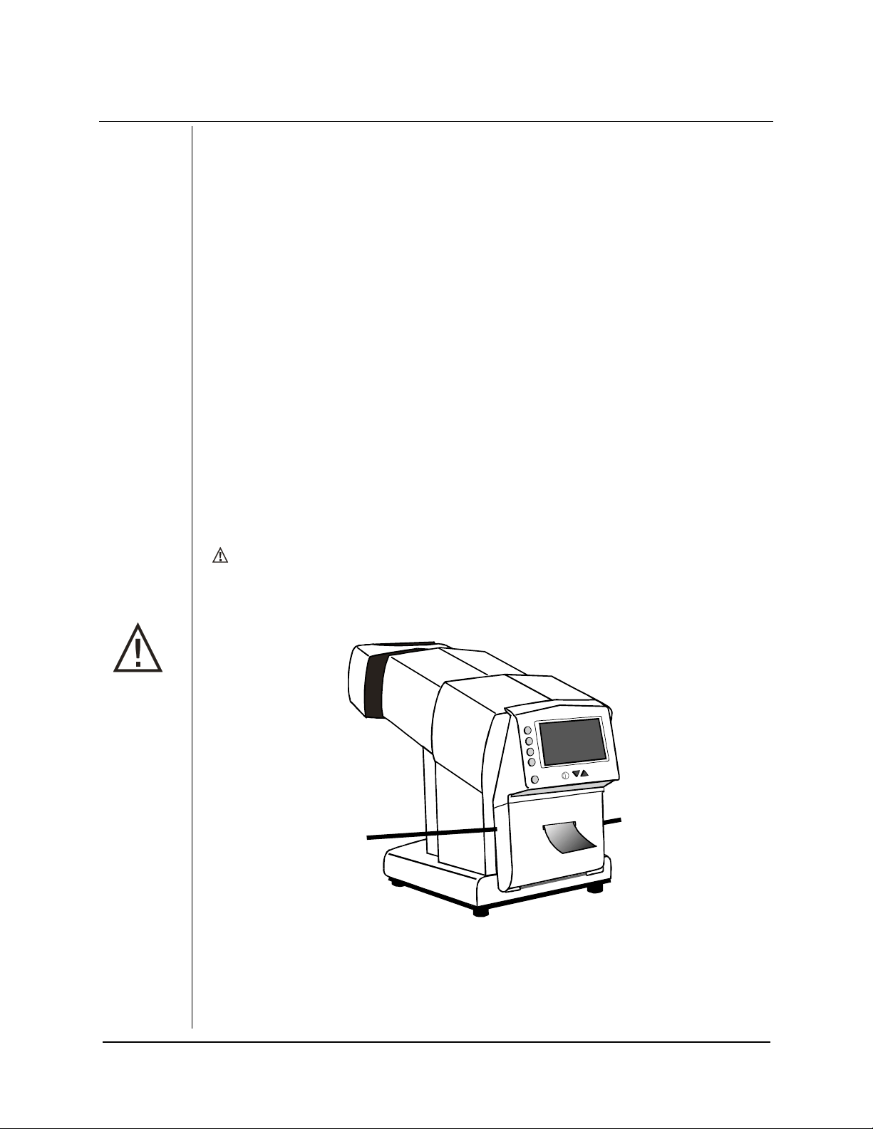
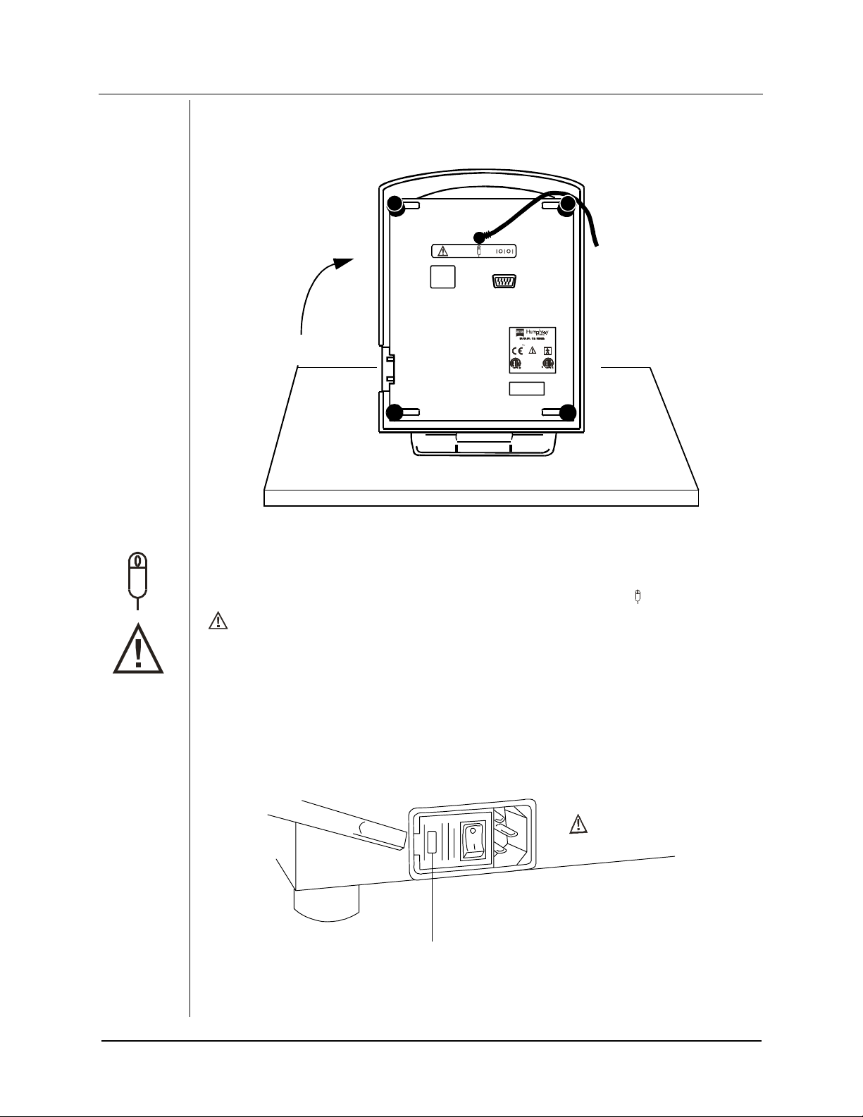
After unpacking the instrument
the finger cutouts on the sides of the door (near the top), and
BEFORE using the pr inter
in the door.
printer.
fields (such as MRI).
Failure to remove the shipping wedge will result in improper operation of the
DO NOT USE the instrument near other equipment which produces strong magnetic
Disconnect from the mains via the appliance inlet.
Use an approved hospital-grade power inlet cord only.
, pull down the
. Close the printer door. Be sure the paper is sticking out through the slot
The video monitor performance may be adversely affected.
printer door
(below the LCD display), using
remove the foam shipping wedge
HUMPHREY FDT VISUAL FIELD INSTRUMENT PLEASE READ/ 1
REV. D 01/00 PN 112098-1
Page 6
PLEASE READ
LCD DISPLAY CONTRAST -
Use the UP and DOWN arrows adjacent to the contrast symbol bel ow
the LCD display to adjust the LCD contrast for optimum viewing, based on lighting conditions.
TYPE BF
- Indicates this is a Type B product with Type BF applied parts; the patient forehead rest
and patient response Button.
SHIPPING and STORAGE TEMPERATURE range
exposed to betwee n
-20° C (-4° F) and +49° C (+120° F)
- Limit the temperatures the instrument is
to avoid possible damage to the
instrument. Refer to the environmental specifications section of the manual for more information.
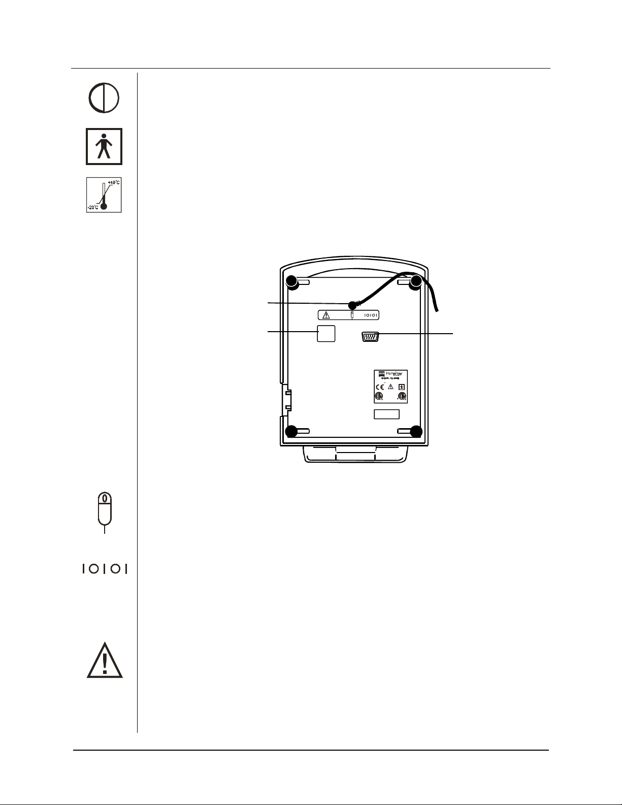
Patient Response
Button Connector
Softwa re Upgrade
Connector
RE F 710 SE RIE S
115V/230V 50/60 Hz 315mA/160mA
UL 2601
IEC 601-1
CSA C22.2
NO. 601-1
74227
PAT. PEND.
MADE IN U.S.A.
Computer
Interface
Connector
PATIENT RESPONSE BUTTON CONNECTOR
- Connect ONLY the patient response button
supplied with the instrument or an approved replacement to the patient response button connector
on the bottom of the instrument. Connection of any other device to the patient response button
connector may damage the instrument or create an unsafe condition and will void the warranty.
COMPUTER INTERFACE CONNECTOR
- Connect ONLY
RS-232 serial compatible
computer
ports to the computer interface connector on the bottom of the instrument. Use the null-modem
configuration computer interface cable supplied with the instrument or an approved replacement
cable. Connection of any other computer port or device to the computer interface connector may
damage the instrument. Refer to the computer interface instructions for additional information.
SOFTWARE UPGRADE CONNECTOR
- The blank label on the bottom of the unit adjacent to this
symbol covers the SOFTWARE UPGRADE CONNECTOR. The blank label should only be removed
during a software upgrade and should be replaced when the upgrade is complete. Refer to the
software upgrade instructions to update the instrument software.
2 / PLEASE READ HUMPHREY FDT VISUAL FIELD INSTRUMENT
REV. D 01/00 PN 112098-1
Page 7
2
INTRODUCTION
ABOUT THE USER’S GUIDE
The USER’S GUIDE is designed to help you understand the capabilities and operation of the
Humphrey FDT Visual Field Instrument with Welc h Allyn ’s FREQUENCY DOUBLING TECHNOLOGY.
To achieve satisfactory results, the operator should read this manual thoroughly before using the
instrument. An FDT Quick Reference Guide is provided for the convenience of experienced
operators.
INTRODUCTION
INSTRUMENT OVERVIEW
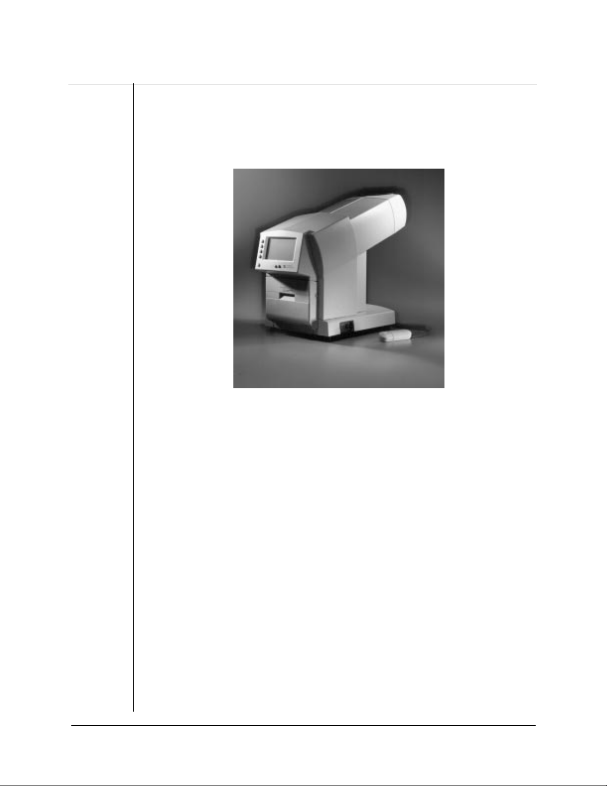
The FDT Vis ual Fi eld Ins tr um ent is an inno v ati v e, efficient, compact and affordable automated visual
field testing instrument. Years of research and clinical trials of Welch Allyn’s patented FREQUENCY
DOUBLING TECHNOLOGY have resulted in an instrument which provides rapid, clinically validated
and user-friendly visual field testing.
Key features of the FDT Visual Field Instrument include:
• Supra-threshold screening tests in less than 1 minute per eye
• Full-threshold tests in approximately 4 minutes per eye
• Easy to use; no special training is needed/minimal operator instruction
• No corrective (trial) lens needed; patients can wear their own correction or none at all
(must only be within 7D of patient’s refraction
• No eye patch needed for the opposite (untested) eye - it’s automatically occluded
• Not affected by ambient lighting - can be used in normal room lighting
• Not affected by pupil size (as small as 2 mm)
• Extensive age-normative reference database incorporated
• World-class clinical validation by leading researchers in the field
• Statist ically signific ant correlation to the Humphrey Field Analyzer
• Software upgrade capability for future enhancements
HUMPHREY FDT VISUAL FIELD INSTRUMENT INTRODUCTION/ 3
REV. D 01/00 PN 112098-1
Page 8
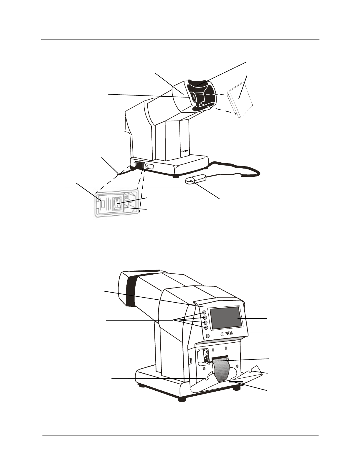
PATIENT’S SIDE INSTRUMENT COMPONENTS
Forehead Rest
INTRODUCTION
Patient Eyepiece
Power Cord
Voltage
Selector
Indicator
Patient Visor
Power Switch
4489
Po wer Cord Inlet
Patient Response Button
OPERATOR’S SIDE INSTRUMENT COMPONENTS
Calibration Cap
Operator
Control Panel
Operator
Buttons (Blue)
Cancel/Backup
Button (Green)
Paper Access Door
Finger Tab
Paper Access Door
Paper Release Lever
Operator LCD
Operator LCD
Display Contrast
Adjustment Buttons
Printer Paper
Paper Access Door
Finger Tab
Paper Printout Slot
4 / INTRODUCTION HUMPHREY FDT VISUAL FIELD INSTRUMENT
REV. D 01/00 PN 112098-1
Page 9
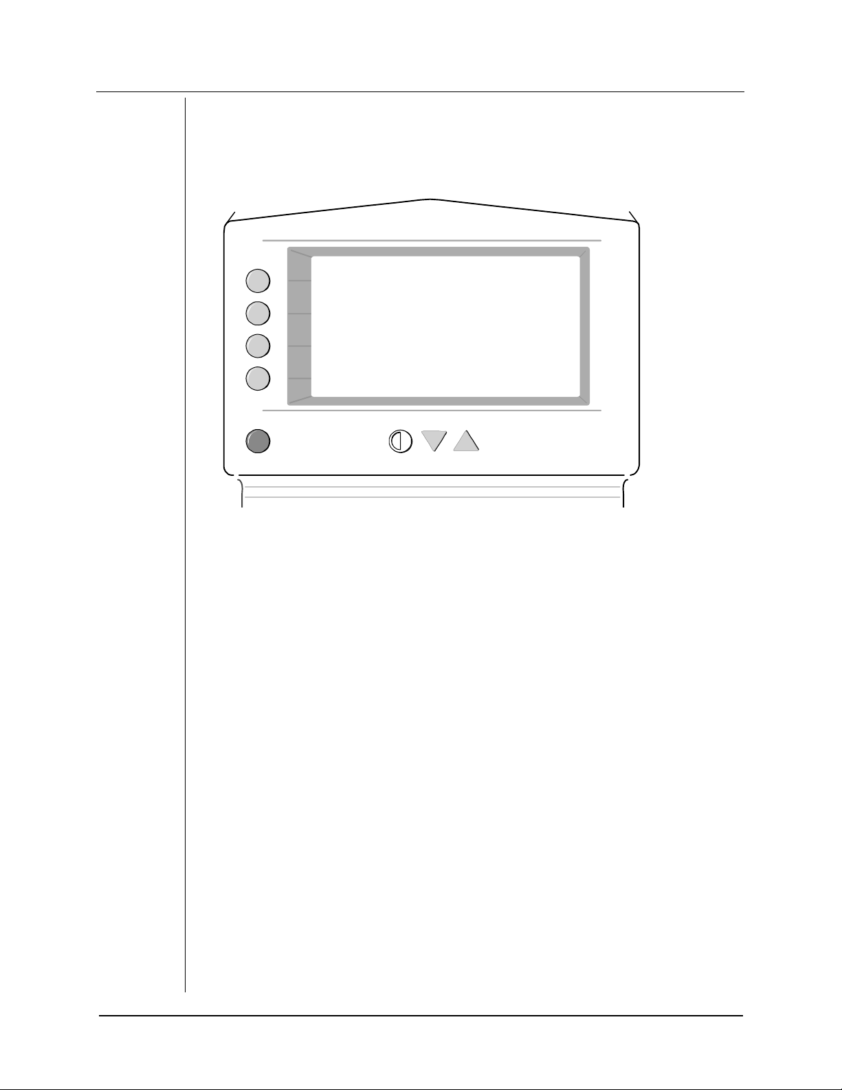
INSTRUMENT COMPONENTS
The instrument has seven Buttons to control the operation of the instrument, located adjacent to
the Operator’s Liquid Crystal Display (LCD).
• Four BLUE Operator Buttons along the left side of the Operator LCD Display
• A GREEN Cancel/Backup Button below the four BLUE Buttons
• Two Operator LCD Display Contrast Adjustment Buttons (Down Arrow and Up Arrow)
adjacent to the Contrast Symbol and directly below the LCD Operator Display
Further below the Operator LCD Display is a Paper Access Door which opens to provide access to
the internal thermal printer for replacement of paper, when needed. The instrument has a sliding
Patient Visor which aids in the selection of the eye to be tested and automatically occludes the
opposite (untested) eye. Detachable Patient Response Button, Power Cord, and Calibration Cap are
also provided.
FDT OVERVIEW
isolates a subset of retinal ganglion cell mechanisms in the magnocellular (M-cell) pathway.
FDT
These M-cells have large diameter fibers and comprise only 3% to 5% of all retinal ganglion cells.
The damage of these cells in the disease process makes FDT efficient and effective for the
detection of visual field loss.
INTRODUCTION
HUMPHREY FDT VISUAL FIELD INSTRUMENT INTRODUCTION/ 5
REV. D 01/00 PN 112098-1
Page 10
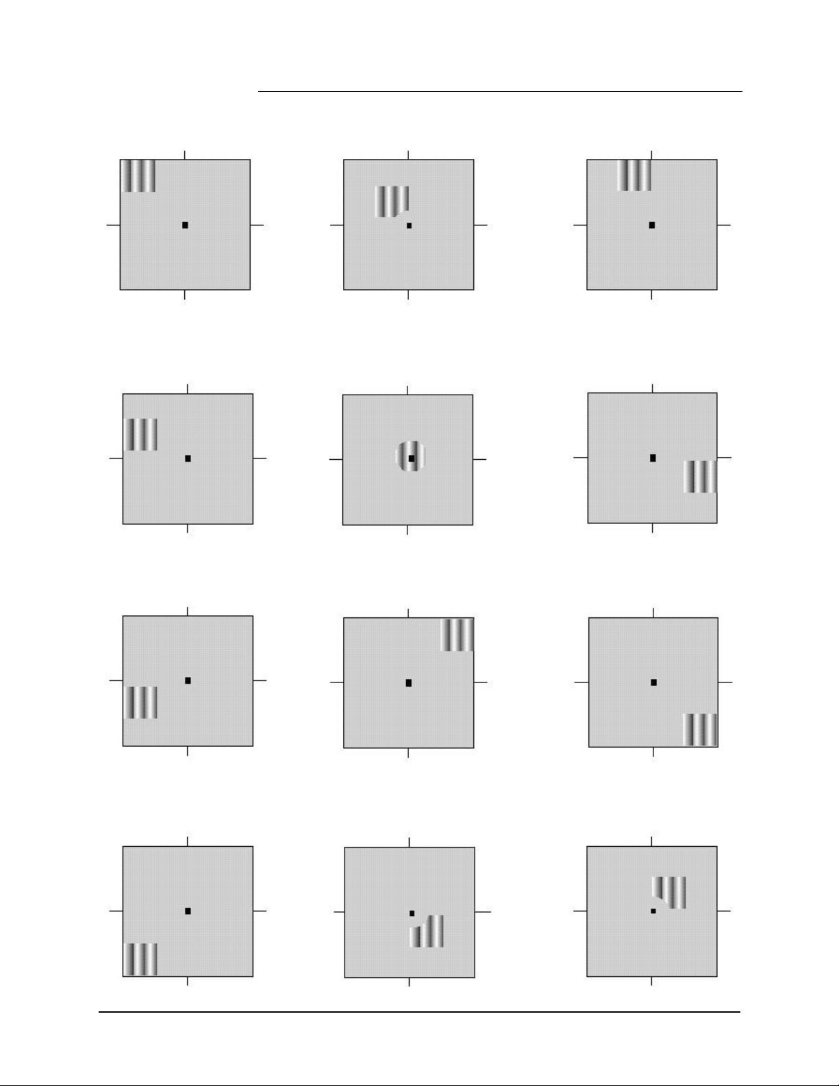
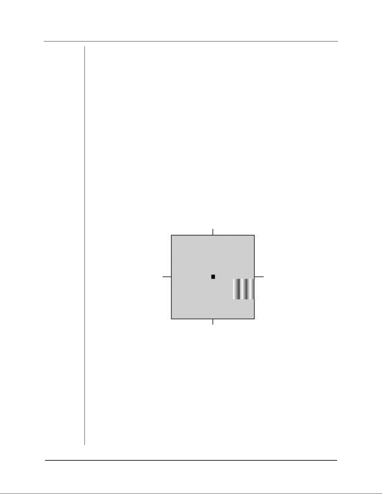
PATIENT’S VIDEO
SCREEN PATTERNS
INTRODUCTION
6 / INTRODUCTION HUMPHREY FDT VISUAL FIELD INSTRUMENT
REV. D 01/00 PN 112098-1
Page 11
3
OPERATING PROCEDURES
UNPACKING
This instrument is designed for use by anyone familiar with the operation as described in this
manual; no special qualif ications are required. Anyone using this instrument shou ld read and
understand the operating instructions manual before using t he instrument. Interpretation of the
results should be performed only by appropriately trained eyecare professionals.
Open the shipping box by carefully cutting the pac king tape securing the top flaps of the box. Lift out
the foam insert containing the Patient Response Button, Power Cord and extra roll of paper. Lift the
instrument ou t of the remaini ng f oam ins ert b y graspi ng the ins tr umen t at the two cu touts pro v ided
and set the instrument on a flat, stable surface. Remove the plastic bag from the FDT Visual Field
Instrument. Use of an adjustable height chair and/or table is recommended when performing
testing.
After you have unpacked the instrument and its components, confirm that you have received the
following items in good condition:
• Humphrey FDT Visual Field Instrument
• Calibration Cap (covering the Patient’s Eyepiece inside the Patient Visor)
• Patient Response Button
• Power Cord (appropriate for local operating voltage)
• Extra roll of paper
RETAIN THE SHIPPING MATERIALS (BOX AND PACKAGING) IN THE EVENT OF SHIPPING
DAMAGE OR FOR RETURN, IF NECESSARY, TO AN AUTHORIZED SERVICE OR DISTRIBUTION
LOCATION AT ANY TIME IN THE FUTURE.
After unpacking the instrument,
using the Finger Tabs on the sides of the door.
the printer.
door.
Close the Paper Access door while guiding Printer Paper through the Paper Slot in the
Failure to remove the shipping wedge will result in improper operation of the printer.
pull down the
Paper Access Door
Remove the foam shipping wedge
(below the LCD display)
before
using
OPERATING PROCEDURES
Paper Access Door
Paper Access Door
Finger Tab
Finger Tab
HUMPHREY FDT VISUAL FIELD INSTRUMENT OPERATING PROCEDURES / 7
REV. D 01/00 PN 112098-1
Page 12
PREPARATION FOR USE AND POWER ON
Patient Side
Tip
Operator Side
RE F 710 SE RIE S
115V/230V 50/60 Hz 315mA/160mA
UL 2601
IEC 601-1
CSA C22.2
NO. 601-1
74227
PAT. PEND .
MADE I N U. S.A.
OPERATING PROCEDURES
While facing the Patient Side of the FDT instrument, tilt the instrument to plug the
Response Butt on
connector into the small roun d connecto r jack. The jack is loca ted underne ath the
Patient
base of the unit (at the center) and near the patient response button symbol .
OPERATING VOLTAGE SELECTION - select the desired operating voltage range, either
115V or 230V, before connecting the power cord to the applian ce inlet conn ec ti on and be f ore
applying power to the instrument. Be sure the proper fuse values are used for each voltage
setting.
connecting the Power Cord and
Before
Voltage Selector Indicator
adjacent to the
applying power to the instrument, be sure the
before
O/I Power Switc h
displays the app r op ria te opera t in g
voltage (115V or 230V).
L
5
1
3
T
-
V
5
1
1
115V
Voltage Selector Indicator
L
0
6
1
T
-
V
0
3
2
To chang e the F us e Carrier/Voltage Selector to the proper operating voltage
be sure the Power
Cord is NOT connected and use a flat screwdriver to pry open the Fuse Drawer Cover. Remove the
8 / OPERATING PROCEDURES HUMPHREY FDT VISUAL FIELD INSTRUMENT
REV. D 01/00 PN 112098-1
Page 13
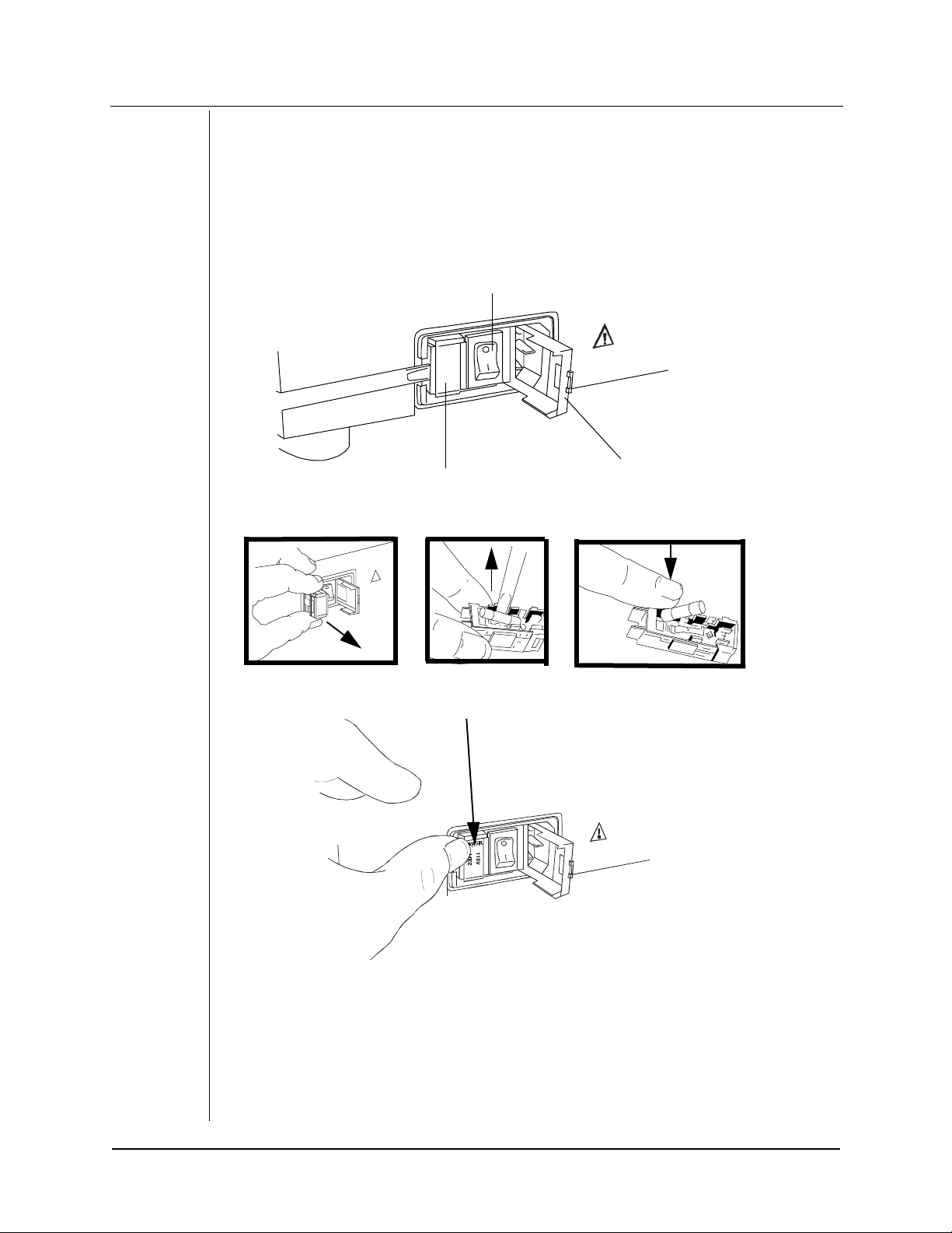
Fuse Carrier/Volta ge Selector, by again using a flat screwdriver, noting the placement of the fuses
before removing them. Remove and replace
them with the value indicated on the fu se rep la cemen t la be l (for 115V use TY PE
and for
230V
fuse TYPE
T .160A 250V
fuse). Rotate the Fuse Carrier/Voltage Selec tor so the prop er
uses, by carefully prying them out and replacing
both
T .315A 250V
fuse
voltage will be visible when the Voltage Selection Door is closed. Re-install the Fuse Carrier. Close
the Fuse Drawer Cover and check to be sure the proper voltage appears in the Voltage Selection
Window. Refer to the Replacement Parts and Accessories section of this manual for fuse part
numbers and ordering information.
Power Switch
5
6
5
3
4
4
9
8
9
563
OPERATING PROCEDURES
Fuse Carrier/Voltage Selector
$
5639
4489
3
5
6
5
Selected Voltage
Fuse Drawer Cover
HUMPHREY FDT VISUAL FIELD INSTRUMENT OPERATING PROCEDURES/ 9
REV. D 01/00 PN 112098-1
Page 14

Plug the appropriate approved hospital grade detachable Power Cord into the Power Cord Inlet on
the operator’s right-hand side and plug the opposite end into a standard power outlet.
/
8
4
6
7
0
9
8
4
4
448 9
/
3
9
4
0
7
9
3
6
5
OPERATING PROCEDURES
Power Switch
To turn the instrument ON
the ON
(I) position
. The instrument will perform internal self-diagnostic checks and after
, switch the
Power Switch (O/I)
approximately 15 seconds, two double beeps will sound and the
the Operator LCD Display. Refer to the troubleshooting section of this manual if the
does not appear.
MENU
: You may need to adjust the
Note
LCD contrast
Power Cord Inlet
, adjacent to the power connector, to
FDT MAIN MENU
will appear on
FDT MAIN
in order to read the Operator LC D Displ ay; use the
triangle shaped buttons below the Operator LCD Display to increase (up-arrow) or decrease (downarrow) the LCD contrast.
FREQUENCY DOUBLING TECHNOLOGY MAIN MENU
RUN PATIENT TEST
RUN DEMONSTRATION
ADVANCE PAPER
Return to Main Menu Decrease Contrast
: the
Note
the
GREEN Button
FDT MAIN MENU
UTILITIES MENU
may be used at any tim e to back-up to the previous menu and to return to
(it may need to be pressed several times to reach the
24 JUN 1997 04:08 PM
Increase Contrast
FDT MAIN MENU
.
10 / OPERATING PROCEDURES HUMPHREY FDT VISUAL FIELD INSTRUMENT
REV. D 01/00 PN 112098-1
Page 15

PREPARING FOR A PATIENT TEST
Remove the CALIBRATION CAP
Patient Ey epi ece w hen the instrument is not in use to minimize the a ccumul ation o f dust a nd de bris
in the Patient Eyepiece.
from the Patient Eyepiece. Replace the calibration cap on the
Select RUN PATIENT TESTS
FULL THRESHOLD C-20 TEST
FREQUENCY DOUBLING TECHNOLOGY MAIN MENU
RUN PATIENT TESTS
RUN DEMONSTRATION
ADVANCE PAPER
UTILITIES MENU
from the
or a
FDT MAIN MENU
FULL THRESHOLD N-30 TEST.
24 JUN 1997 04:08 PM
to prepare for a
SCREENING C-20 TEST,
OPERATING PROCEDURES
Note
: Once
RUN PA TIENT TES TS
is selected, typical FDT stimu lus presen tations are automa tically
displayed to demonstrate the test to the patient until the test actually starts.
HUMPHREY FDT VISUAL FIELD INSTRUMENT OPERATING PROCEDURES/ 11
REV. D 01/00 PN 112098-1
Page 16
Enter the Patient’s Age
The unit will start with an
by 10 year increments (e.g. to 60, 70, and so on). Select
AGE
the top)
top)
and so on). Select
to decrease the
to increase the
ACCEPT SETTING (BOTTOM BLUE Butto n)
AGE
+10 YEARS
AGE: 50
- 10 YEARS
+1 YEAR
of 50 years. Select
AGE
by 1 0 year increments. Select
AGE
in 1 year increments to adjust to the exact age of the patient (e.g. 51, 52,
ENTER PATIENT AGE
+10 YEARS (TOP BLUE Button)
-10 YEARS (2nd BLUE Button from
+ 1 YEAR (3rd BLUE But t on fr om the
when the correct
to increase the
is display e d.
AGE
OPERATING PROCEDURES
Slide the
Patient Visor
ACCEPT SETTING
to the
right eye test position
24 JUN 1997 04:08 PM
(this is to your right when looking at the
patient from the operator’s side).
: If you want to
Note
the
left eye test position
and select
SKIP RIGHT EYE
skip
the
right eye
(i.e., only test the left eye), then
slide
the
Patient Visor
now (this is to your left when facing the patient from the operator’s side)
.
to
Prepare the Patient
Place the
Patient Response Button
patient to place their forehead on the
video screen
. Adjust the
height
the patient. Confirm that the pa tien t ca n se e the enti re li t vid eo s creen , inc lu din g al l four corners, in
the Patient Eyepiece and the black dot in the middle of the screen.
: Be sure the patient is positioned comfortably (not hunched over) by adjusting the height of
Note
the chair or table (or both).
in the patient’s hand and show them how to press it. As k the
Forehead Rest
and look into the
Patient Eyepiece at the
of the chair or table (or both) to obtain a comfortable position for
Patient Refraction
The
their refraction). If a patient is wearing glasses, confirm that their glasses frame does not obscure
any of the lit po rtion of the di spla y. Ask the patient to remo ve their glasses for the test if their l enses
or contact lenses are tinted or change c ontra s t based on lighting conditions (photochromatic). Tests
may be taken with bifocal or progressive lenses (unless the progressive lenses have more than 3D
equivalent sphere distance correction).
12 / OPERATING PROCEDURES HUMPHREY FDT VISUAL FIELD INSTRUMENT
test may be taken with or without the patient’s correction (if the patient is within 7D of
FDT
REV. D 01/00 PN 112098-1
Page 17

Explain the Test Procedure to the Patient
“A demonstration of the test is running now. Can you see the black dot in the center and the entire
lit video screen? You need to stare at the black dot in the center of the screen during the entire
test.”
“From time to time, you will see patterns of
briefly appear in different areas of the screen. The patterns will
other times be
you see the
butto n once
by pressing the Button to respond to the patterns.”
“It is OK to blink and a good time to blink is when you press the response Button. If you need to
rest or ask questions during the test, you can pause the test at any time by pressing and holding
down the response Button. Do you have any questions? Do you understand how to take the test?”
“I will now start the test. There will be a few brief flashes and then the test will begin. Press the
response Button once each time you see the
pat terns, e v en if the bars are v ery faint. Ple ase remember to
the screen
very distinct
flickering black and white vertical bars
. Can you see thes e patterns in the demonstration r unnin g no w? You may practice now
during the entire test.”
. You are not expected to see the bar patterns at all times. Each time
flickering black and white vertical bars
sometimes
of one of the patterns,
flicke r ing blac k and whit e ver tical bars
stare at the bl ack dot in the cent er of
be
press the response
that will
very faint
of one of the
and at
OPERATING PROCEDURES
HUMPHREY FDT VISUAL FIELD INSTRUMENT OPERATING PROCEDURES/ 13
REV. D 01/00 PN 112098-1
Page 18

: A separate
Note
DEMONSTRATION
the patient’s understanding of the test, if needed. To run a practice test, select
DEMONSTRATION (2nd BLUE Button from the top)
test is available from the
from the
FDT MAIN MENU
RUN
FDT MAIN MENU
to help facilitate
. A
demonstration of the test stimulus automatically begins. The patient should use this time to
become familiar with the test and practice using the
PA TIEN T RESPON SE BUTTON
(Ask the
patient to look into the Patient Eyepiece within the P atien t V isor and th en t est the p rocedu re.) P res s
the GREEN Button to cancel the practice test and return to the
FREQUENCY DOUBLING TECHNOLOGY MAIN MENU
RUN PATIENT TESTS
RUN DEMONSTRA TION
ADVANCE PAPER
FDT MAIN MENU.
OPERATING PROCEDURES
UTILITIES MENU
Be sure to prepare the patient as described above before running a practice test
24 JUN 1997 04:08 PM
.
RUNNING A SCREENING OR THRESHOLD PATIENT TEST
Select either RUN SCREENING TEST C-20, RUN FULL THRESHOLD C-20 TEST or RUN FULL
THRESHOLD N-30 TEST
immediately
after a momentary check for proper calibration.
RUN SCREENING C-20 TEST
RUN FULL THRESHOLD C-20 TEST
RUN FULL THRESHOLD N-30 TEST
SKIP RIGHT EYE
GRN BUTTON CANCELS 24 JUN 1997 03:55 PM
from the
RIGHT EYE TEST MENU
RIGHT EYE TEST M ENU
. The right eye test will begin
: To
Note
(BOTTOM Operator Button from the top)
: The Operator LCD Display will indicate if there is too much ambient light to perform a reliable
Note
skip
the
right eye
test and proceed directly to the left eye test, select
before
selecting a
SCREENING
or
SKIP RIGHT EYE
THRESHOLD
test.
test. Lower the room lighting or change the test location until suitable test conditions are achieved.
14 / OPERATING PROCEDURES HUMPHREY FDT VISUAL FIELD INSTRUMENT
REV. D 01/00 PN 112098-1
Page 19

Also, if the Patient Response Button is not connected or the Patient Visor is in the wrong eye
position, this will be indicated on the Operator LCD Display.
FULL THRESHOLD C-20 TEST (RIGHT EYE)
PERCENT COMPLET E:
2%
PATIENT RESPONSE : N
FIXATION ERRS : 0/0
FALSE POS ERRS : 0/0
FALSE NEG ERRS : 0/0
GRN BUTTON PAUSES 24 JUN 1997 04:05 PM
OPERATING PROCEDURES
The
PERCENT COMPLETE
ERRORS, FALSE POS ERRORS
scale, field location being tested,
and
FALSE NEG ERRORS
are displayed on the Operator LCD
PATIENT RESPONSE, FIXATION
Display during the test. Remind the patient to keep looking at the dot in the middle of the screen
and inform them of the approximate percent complete at 3 or 4 times during the test to encourage
good patient complia nce. Mo nitor the catch trials
NEG ERRS)
during the test. The catch trial display fields will be highlighted on the Operator LCD
(FIXATION ERRS, FALSE POS ERRS, and F A LSE
Display if 2 or more catch trials have been responded to by the patient. A high ratio on any of the
catch trials indicates unreliable results and that the test should be restarted or repeated.
: You can
Note
test. F oll o w t he Ope rator LCD Di sp la y in structions to
a
down the
the
. The patient can also PAUSE the test (for a break, etc.) by simply pressing and holding
pause
Patient Response Button
Patient Response Button.
(GREEN Button)
Note: A SCREENING C-20 TEST
THRESHOLD C-20 TEST
THRESHOLD N-30 TEST
PAUSE
or
RE-START
the test by pressi ng th e
GREEN Butt on
CONTINUE TEST
. The test will resume automatically once the patient releases
During patient pause, you may also select
so that the test will remain paused until you restart it.
takes less than
takes approx imately
1 minute
4 minutes
(per eye) to complete, a
(per eye) to complete and a
takes about 4-1/2 minutes .
at any time during the
or to
RE-START TEST
OPERATOR PAUSE
FULL
FULL
from
HUMPHREY FDT VISUAL FIELD INSTRUMENT OPERATING PROCEDURES/ 15
REV. D 01/00 PN 112098-1
Page 20

At the end of the right eye test, the Operator LCD Display will prompt for a left eye test. Slide the
Patient Visor
to the
operator’s side).
left eye test position
Prepare the patient
(this is to your left when facing the patient from the
. Select
RUN SCREENING C-20 TEST (TOP Operator
Button), RUN FULL THRESHOLD C-20 TES T (2nd Oper a to r Button from the top), or R UN FULL
THRESHOLD N-30 TEST (3r d Oper at or Bu t t on fr om the t op)
begin the left eye test
immediately
RUN FULL THRESHOLD C-20 TEST
SKIP LEFT EYE
GRN BUTTON CANCELS 24 JUN 1997 04:10 PM
after a momentary check for proper calibration.
LEFT EYE TEST MENU
from the
LEFT EYE TEST ME NU
to
OPERATING PROCEDURES
Note
: To
skip
the
the results menu.
left eye
test, select
SKIP LEFT EYE (BOTTOM Operator Button)
to proceed to
16 / OPERATING PROCEDURES HUMPHREY FDT VISUAL FIELD INSTRUMENT
REV. D 01/00 PN 112098-1
Page 21

DISPLAYING & PRINTING THE TEST RESULTS
You can both view th e res ul ts on the Ope rat or LCD Dis pl ay and print them out from the tes t res ul ts
menu. At the end of a test, the results will be automatically printed (default set-up is automatic
printing) and then the test results menu will automatically appear on the Operator LCD Display.
Select either
RESULTS (BOTTOM Operator Button)
on the Operator LCD Display. Use the
you to toggle between the eye results or to return to the
necessary). Select
VIEW RIGHT EYE RESULTS (3rd Operator But t on fr om the t op) or VIEW LEFT EYE
to view the indiv id ual eye results for the patient just tested
GREEN Button
to back-up to the previous screen to allow
FDT MAIN MENU
PRINT REPORT (TOP Operator Button)
to obtain additional copies of the
results for the patient just tested (you can print as many copies as you’d like).
FULL THRESHOLD C-20
PRINT REPORT TEST DATE/TIME:
24 JUN 1997 04:05 pm
PATIENT AGE: 50
ADVANCE PAPER
RIGHT EYE:
TEST DURATION: 03:40
VIEW RIGHT EYE LEFT EYE:
RESULTS TEST DURATION: 04:17
VIEW LEFT EYE
RESULTS 24 JUN 1997 04:20 pm
(press it twice if
OPERATING PROCEDURES
: Once the test is completed, you can also select
Note
Button from the top)
from the
FDT MAIN MENU
LAST PATIENT RESULTS (3rd Operator
to display or print out the results of the patient
just tested. The results of the most recently tested patient will remain in memory
begin a new test or until the instrument power is turned off.
only until you
HUMPHREY FDT VISUAL FIELD INSTRUMENT OPERATING PROCEDURES/ 17
REV. D 01/00 PN 112098-1
Page 22

USING THE RS-232 SERIAL COMPUTER INTERFACE
RE F 710 SE RIE S
115V/230V 50/60 Hz 315mA/160mA
UL 2601
IEC 601-1
CSA C22.2
NO. 601-1
74227
PAT. PEND .
MADE I N U. S.A.
The instrument includes an external serial RS-232 serial computer interface connector located on
the bottom of the instrument. This interface provides the user with the ability to upload results from
the instrumen t to a compute r when the ac cessory computer in terf ace c able and software are used.
For detailed information on using the computer interface, reference the FDT PC operating
instructions, available from authorized representatives.
OPERATING PROCEDURES
UNDERSTANDING THE SCREENING C-20 TEST RESULTS
A plot of the 17 visual field locations tested will be pr inte d (see sample s on the following pages) and
displayed on the Operator LCD Display for the supra-threshold
eye test ed . Each test location will be either
of shading
“WITHIN NORMAL LIMITS”
.
- The patient
opportunity) when tested at the contrast level that
clear white
responded positively
99% (P > = 1%)
SCREENING C-20 TEST
or will hav e
one of three possib le levels
(on either the first or second
of normal subjects of the same
age would respond to for the test location with this shading.
“MILD RELATIVE LOSS”
normative contrast level
- The patient
(P = 1%)
after being
failed to respond positively
given 2 opportunities
when tested at the 1% age
to do so (the instrument will
re-test any point mis s ed a t the 1% age normative level a second time ) for the test location with this
shading.
“MODERATE RELATIVE LOSS”
opportunities
the
0.5%
“SEVERE L OSS”
to do so; t wice at the 1% age normative contrast level
age normative contrast level
- The patient
- The patient
(P = 0.5%)
failed to respond positively
for the test location with this shading.
failed to respond positively
after b ein g
after being
(P = 1%)
and a third time at
given 4 opportunities
do so for the test locations with this shading; the 3 opportunities listed above and a fourth at the
maximum
contrast level of the instrument.
for each
given 3
to
18 / OPERATING PROCEDURES HUMPHREY FDT VISUAL FIELD INSTRUMENT
REV. D 01/00 PN 112098-1
Page 23

When reviewing the results of the visual field test, careful consideration must be given to the
reliability ind ica tors
report and Operator LCD Display for the screening test. They are an important measure of patient
reliability in taking the test (and of the reliability of the results). They are indicated as a ratio of the
number responded to the number prese nted. For example,
to 1 of the 3 catch trials presented.
(catch tria ls). The follo win g tw o test reliability indicators appear on the printe d
indicates that the patient resp onded
1/3
FIXATION ERRS : 0/3
FALSE POS ERRS : 0/3
FIXATION ERRORS
the blind spot versus the total number of times fixation was tested (i.e., total number of targets
placed in the blind spot). Three
Fixation errors indicate the patient is not maintaining good fixation during the test, is misaligned, or
does not understand the test.
FALSE POSITIVE ERRORS
in the testing sequence (i.e., no target presented) versus the total number of “pauses” in the
testing sequence. Three
False positive errors indicate the patient is pressing the Button even if the patient doesn’t see any
patterns or does not understand the test.
- The ratio of the number of times the patient responded to a target placed in
FIXATION catch trials
- The ratio of the number of times the patient responded to a “pause”
FALSE POSITIVE catch trials
will be randomly presented f o r each eye.
will be randomly presented for each eye.
UNDERSTANDING THE FULL THRESHOLD C-20 AND N-30 TEST RESULTS
A plot of the 17 or 19 visual field locations tested will be printed (see samples on the following
pages) and a combination pl ot will be displayed on the Operator LCD Display for the
THRESHOLD C-20 and N-30 TEST
numerical contrast th reshold l e v el in units o f dB for each location tested. The second printed results
plot is a deviation plot and will be either
shading
combination plot displayed on the Operator LCD Display will indicate both th e numerical cont rast
threshold level and the shading for each location tested.
The patient achieved a threshold level in the range that
same age achieved for the test locations with this shading.
The probability is less than
threshold level that this patient achieved for the test locations with this shading.
The probability is less than
threshold level that this patient achieved for the test locations with this shading.
corresponding age normative significance levels for each locati on tested. The results
5% (P < 5%)
2% (P < 2%)
for each eye tested. The first printed results plot will contain a
clear white
that a normal subject of the same age would perform at the
that a normal subject of the same age would perform at the
or will have
95% (P > = 5%)
one of
four
of normal subjects of the
FULL
possible levels of
OPERATING PROCEDURES
The probability is less than
threshold level that this patient achieved for the test locations with this shading.
The probability is less than
the threshold level that this patient achieved for the test locations with this shading. This shading
will also occur if the patient
will be indicated).
dB
1% (P < 1%)
0.5% (P < 0.5%)
failed t o r e spond
that a normal subject of the same age would perform at the
that a normal subject of the same age would perform at
at the
maximum contrast level
of the instrument (
HUMPHREY FDT VISUAL FIELD INSTRUMENT OPERATING PROCEDURES/ 19
REV. D 01/00 PN 112098-1
0
Page 24

When reviewing the results of the visual field test, careful consideration must be given to the
reliability indicators
(catch trials). The following three indicators appear on the printed report and
on the LCD Display fo r the threshold test. They are an important measure of patient reliability in
taking the test (and of the reliability of the results). They are indicated as a ratio of the number
responded to the number presented. For example,
indicates that the patient responded to 1 of
1/3
the 3 catch trials presented.
FIXATION ERRS : 0/0
FALSE POS ERRS : 0/0
FALSE NEG ERRS : 0/0
OPERATING PROCEDURES
FIXATION ERRORS
- The ratio of the number of times the patient responded to a target placed in
the blind spot versus the total number of times fixation was tested (i.e., total number of targets
placed in the blind spot). Six
FIXATION catch trials
will be randomly presented for each eye in the
C-20 TEST and N-3 0 TES T. Fixation errors indicate the p atient i s not main taining good fix ation d uring
the test, is misaligned, or does not understand the test.
FALSE POSITIVE ERRORS
- The ratio of the number of times the patient responded to a “pause”
in the testing sequence (i.e., with no target presented) versus the total number of “pauses” in the
testing sequence. Six
FALSE POSITIVE catch trials
will be randomly pres ente d for eac h eye in the
C-20 TEST, eight in the N-30 TEST. False positive errors indicate the patient is pressing the Button
even if patient does not see any patterns or the patient does not understand the test.
FALSE NEGATIVE ERRORS
- The rati o o f the nu mb er o f ti mes th e p ati ent did n ot re sp ond to a test
pattern at the maximum possible contrast level of the instrument versus the total number of times
that maximum possible contrast level patterns were tested. Three
FALSE NEGATIVE catch trials
will be randomly presented for each eye in the C-20 TEST, five in the N-30 TEST. False negative
errors indicate the pa tie nt is li kely to not be paying a ttention, does not understand the test, or has a
severe loss at the location of the FALSE NEGATIVE catch trial(s).
For the threshold tests, the device utilizes a staircase threshold strategy known as a
1
Binary Search (MOBS)
threshold scores) is between
Minimum Contrast
(2048/c)*10*H where c ranges from 1 (minimum contrast) to 2048 (maximum contrast) and H
log
10
is approximately 2. Note that
inconsistent patient responses which do not meet the
. The range of possible threshold level values for the
0 dB Maximum Contrast
(lowest patient sensitivity) and
highest patient sensitivity). The formula used to calculate the dB values is
will be displa yed, if the threshold c annot be determined due to
XX dB
threshold criteria. The magnitude of
MOBS
Modified
raw data
(patient
56 dB
the threshold level values is directly correlated to the Humphrey Field Analyzer values.
The device also provides
MD & PSD
global statistical indices calculated from points over the entire
visual field for the threshold test. These indices reduce the individual threshold scores to a single
number to provide o v eral l information about the entire visual field. T he magnitude of the
values are directly correlated to the Humphrey Field Analyzer
MD & PSD
indices. The actual
MD & PSD
formulas used for the MD & PSD indices calculations can be found in the references (2, 3).
20 / OPERATING PROCEDURES HUMPHREY FDT VISUAL FIELD INSTRUMENT
REV. D 01/00 PN 112098-1
Page 25

“The MD (Mean Deviation)
index signifies overall severity of field loss. It is affected both by the
degree of loss and the number of affected locations. A positive number indicates that the average
sensitivity is above the average normal for age, whereas a negative number indicates that the
average sensitivity is below the average normal value.”
2
When the MD value is
LESS
than that of
of normal FDT fields, the percentile probability is
95%
given (P < 5%, P < 2%, P < 1%, or P < 0.5%) on the Operator LCD Display and on the printed
report.
“The
PSD (Pattern Standard Deviation)
index is the standard deviation of the difference of each
sensitivity value from an expected value (based on the normal value at that location and the mean
deviation index), each difference weighted according to the variance of the normal values at that
point. The
becomes large as some points are more affected than others, and thus the
localized change in the field.”
When the
is small in a no rmal fi eld, or in a fiel d wher e all points are eq ually abno rmal. T he
PSD
is an index of
PSD
3
PSD
value is
GREATER
than that of
of normal FDT fields, the percentile probability
95%
PSD
is given (P < 5%, P < 2%, P < 1%, or P < 0.5%) on the Operator LCD Display and on the printed
report.
OPERATING PROCEDURES
1 Tyrrell RA, Owens DA: A New Technique to Rapidly Assess the Resting States of the Eyes and Other
Threshold Phenomena: the Modified Binary Search (MOBS) Whitely Psychology Laboratories ,
Pennsylvania State University.
2 Anderson, DR: Automated Static Perimetry Mosby Year Book, St. Louis, 1992; p. 84.
3 Anderson, DR: Automated Static Perimetry Mosby Year Book, St. Louis, 1992; p. 86.
HUMPHREY FDT VISUAL FIELD INSTRUMENT OPERATING PROCEDURES/ 21
REV. D 01/00 PN 112098-1
Page 26

SCREENING C-20 TEST RESULTS SAMPLE
SCREENING C-20
NAME _________________
AGE 67 ID ___________
30 JUN 1997 03:02 pm
RIGHT EYE
Test duration : 00:43 min
Deviation
O
30
FIXATION ERRS 0/3
FALSE POS ERRS 0/3
LEFT EYE
Test duration : 00:40 min
OPERATING PROCEDURES
Deviation
FIXATION ERRS 0/3
FALSE POS ERRS 0/3
WITHIN NORMAL LIMITS
MILD RELATIVE LOSS
MODERATE RELATIVE LOSS
SEVERE LOSS
30
O
22 / OPERATING PROCEDURES HUMPHREY FDT VISUAL FIELD INSTRUMENT
REV. D 01/00 PN 112098-1
Page 27

THRESHOLD C-20
TEST RESULTS
SAMPLE
FULL THRESHOLD C-20
NAME _________ ___ _____
AGE 55 ID ___________
01 JUL 1997 12:1 3 a m
RIGHT EYE
Test duration : 03:28 min
Threshold (dB)
35
34
32
30
31
31
35
35
31
30
31
32
3531
30
34
31
Deviation
O
30
LEFT EYE
Test duration : 04:13 min
Threshold (dB)
34
30
33
31
30
31
30
33
29
32
33
31
29
31
29
28
28
Deviation
MD +0.88 dB
PSD +2.97 dB
30
OPERATING PROCEDURES
O
MD +2.54 dB
PSD +2.75 dB
FIXATION ERRS 0/6
FALSE POS ERRS 0/6
FALSE NEG ERRS 0/3
FIXATION ERRS 0/6
FALSE POS ERRS 0/6
FALSE NEG ERRS 0/3
Probability Symbols
P >= 5%
P < 5%
P < 2%
P < 1%
P < 0.5%
HUMPHREY FDT VISUAL FIELD INSTRUMENT OPERATING PROCEDURES/ 23
REV. D 01/00 PN 112098-1
Page 28

THRESHOLD N-30 TEST
RESULTS SAMPLE
OPERATING PROCEDURES
FULL THRESHOLD N-30
NAME _________ ___ _____
AGE 79 ID ___________
30 JUN 1997 06:45 am
RIGHT EYE
Test duration : 04:07 min
Threshold (dB)
36
41
36
30
31
37
41
36
40
40
40
37
4045
40
Deviation
O
30
LEFT EYE
Test duration : 04:40 min
Threshold (dB)
38
28
40
36
36
32
36
34
33
35
35
36
36
36
Deviation
MD +4.07 dB
PSD +4.01 dB
40 32
40
34
33
34 34
36
32
O
30
MD +6.10 dB
PSD +4.36 dB
FIXATION ERRS 0/6
FALSE POS ERRS 0/8
FALSE NEG ERRS 0/5
FIXATION ERRS 0/6
FALSE POS ERRS 0/8
FALSE NEG ERRS 0/5
Probability Symbols
P >= 5%
P < 5%
P < 2%
P < 1%
P < 0.5%
24 / OPERATING PROCEDURES HUMPHREY FDT VISUAL FIELD INSTRUMENT
REV. D 01/00 PN 112098-1
Page 29

CALIBRATION AND SET-UP,
4
FREQUENCY DOUBLING TECHNOLOGY MAIN MENU
RUN PATIENT TESTS
RUN DEMONSTRATION
ADVANCE PAPER
UTILITIES MENU
MAINTENANCE AND TROUBLESHOOTING
24 JUN 1997 04:00 pm
CALIBRATION AND SET-UP
The
UTILITIES MENU
unless calibration or a change of the instrument set-up defaults is needed
(set-ups are set to defaults and date and time (EST) have been pre-set).
on the
FDT MAIN MENU
should not be needed
Set Date and Time
To set the date and time, select
Button)
MENU (TOP Operator Button)
CLOCK MENU (TOP Operator Button)
MENU
from the
.
FDT MAIN MENU
SET-UP INSTRUMENT MENU
RUN SELF-CALIBRATION
INSTRUMENT TESTS MENU
UTILITIES MENU (BOTTOM Operator
then select
in the
UTILITIES MENU
in the
UTILITIES MENU
SET-UP INSTRUMENT
and select
SET-UP INSTRUMENT
SET
ABOUT FREQUENCY DOUBLING TECHNOLOGY
24 JUN 1997 04:01 pm
SET-UP INSTRUMENT MENU
SET CLOCK MENU
SET-UP OPTIONS MENU
PRINT SET-UP REPORT
24 JUN 1997 04:01 pm
TROUBLESHOOTING
CALIBRATION AND SET-UP,
MAINTENANCE AND
HUMPHREY FDT VISUAL FIELD INSTRUMENT SET UP & MAINTENANCE / 25
REV. D 01/00 PN 112098-1
Page 30

Set-up Instrument Options
Select
NEXT CHOICE (3rd Operator Button from the top)
clock setting you want to change. (V)
and (W)
setting. Select
correct CLOCK
return to the
DECREASE (2nd Operator Button from the top)
ACCEPT SETTINGS (BOTTOM Operator Button)
settings are displayed. Press the
FDT MAIN MENU
V
INCREASE YEAR: 1997
MONTH: JUN
W
DECREASE DAY: 24
HOUR: 4 pm
NEXT CHOICE MINUTE: 2
12 HOUR FORMAT
ACCEPT SETTINGS
INCREASE (TOP Operator Button)
.
SET CLOCK MENU
to select the
to change the
GREEN Button
24 JUN 1997 04:02 pm
when the
twice to
CALIBRATION AND SET-UP,
MAINTENANCE AND
TROUBLESHOOTING
To
SELECT LANGUAGE
(2nd Operator Button from the top)
Operator But ton)
or
from the
OPTIONS
, select
. Select
SET-UP OPTIONS MENU
SELECT LANGUAGE (top
SET-UP OPTIONS MENU
to c hoo se th e d es ired
language for the Operator LCD Display and results printout. Use
CHOICE (3rd Opera tor But t on from the top)
to select the desired language
from the list.
Select
ACCEPT SETTINGS (Bottom Operator Button)
language choice is highlighted. Press the
return to the
Select
OPTIONS MENU
FDT main menu
OPTIONS (2nd Operator Button from the top)
to change instrument default settings.
.
GREEN Button
when the desired
three times to
from the
Select
NEXT CHOICE (3rd Operator Button from the top)
setting to change. Select
TOGGLE ON/OFF (Top Operator Button)
change the highlighted setting. The settings include:
AT EACH BUTTON PRESS
and
AUTO PRINT REPORT AFTER TEST
MAKE CLICK SOUND
to select the
are selected as defaults.
Select
ACCEPT SETTINGS (BOTTOM Operator Button)
options are set. Press the
MAIN MENU
Select
.
RESET TO DEFAULTS (3rd Operator button from the top)
SET-UP OPTIONS MENU
GREEN Button
and
ACCEPT SETTINGS
three times to return to the
to restore th e options to factory defaults. Press the
times to return to the
FDP MAIN MENU
.
when the desired
in the
OPTIONS MENU
GREEN Button
NEXT
SET-UP
to
. Both
FDT
in the
three
26 / SET UP & MAINTENANCE HUMPHREY FDT VISUAL FIELD INSTRUMENT
REV. D 01/00 PN 112098-1
Page 31

FREQUENCY DOUBLING TECHNOLOGY MAIN MENU
RUN PATIENT TESTS
RUN DEMONSTRATION
ADVANCE PAPER
UTILITIES MENU
24 JUN 1997 04:00 pm
Calibration
This instrument does not require scheduled calibration. The instrument
calibration is checked each time the instrument is powered ON and at the
start of each test to be sure the unit is properly calibrated. If the instrument
detects the need for calibration, the Operator LCD Display will display a
needs calibration warning. If not calibrated when the needs calibration
warning is displayed, the unit will continue to operate normally until the unit
reac hes the ca libra tion li mits. Once the c alibra tion l imits are rea ched, the unit
will not operate normally until a calibration is completed successfully.
Calibration may be performed at any ti me, not only when requested by the
instrument.
To calibrate the instrument, select
Button)
from the
FDT MAIN MENU
(2nd Operator Button from the top)
UTILITIES MENU (BOTTOM Operator
and then
in the
RUN SELF-CALIBRATION
UTILITIES MENU
. Follow the
Operator LCD Display instructions to start the calibration. The calibration will
take several minutes and requires no operator interaction during calibration. If
the calibration cannot be completed successfully, repeat the
CALIBRATION
sequence again (up to 3 times). If SELF-CALIBRATION cannot
RUN SELF-
be completed after 3 attempts, record the information on Operator LCD
Display and contact an authorized customer service representative for
assistance.
UTILITIES MENU
SET-UP INSTRUMENT MENU
RUN SELF-CALIBRATION
INSTRUMENT TESTS MENU
ABOUT FREQUENCY DOUBLING TECHNOLOGY
24 JUN 1997 04:01 pm
CALIBRATION AND SET-UP,
MAINTENANCE AND
TROUBLESHOOTING
Note
: Be sure to
cover
the
Patient Eyepiece
with the Calibration Cap
shipped with each unit. If the Calibration Cap is not available, substitute
something that will temporaril y block light from entering the Pati ent Ey epiece
or perform the calibration in a completely darkened room (black cloth over
Patient Visor, etc.). The Operator LCD Display will indicate if there is too
much ambient light to complete the calibration.
HUMPHREY FDT VISUAL FIELD INSTRUMENT SET UP & MAINTENANCE / 27
REV. D 01/00 PN 112098-1
Page 32

Softw are Upgrade
This instrument is designed with the ability to upgrade the operating
software. For detailed software upgrade information, reference the software
upgrade instructions available from authorized representatives.
The cur r en t s oftware version is available in the
the bottom of the each
RESULTS PRINT-OUT.
ABOUT FDT SCREEN
and on
MAINTENANCE
This instrument requires no preventive inspection or maintenance. The only
user maintenance re quired is replacing th e printer pa per and s urfa ce cleanin g
as necessary.
Printer Paper Replacement
REF 11260
To load a new roll of paper, pull down the
Operator LCD Display) using the Finger Tabs on the sides of the door (near
the top). Remove the empty paper spool from the paper well.
Unwrap the paper from its bag, loosen the leading edge of the paper from
the roll, and place the new roll of paper into the paper well with the
edge of the paper facing toward the outside
the diagram on the inside of the printer door).
Paper Access Door
of the unit (toward you – see
(below the
leading
CALIBRATION AND SET-UP,
MAINTENANCE AND
TROUBLESHOOTING
Place the leading edge of the paper onto the metal bar and push it into the
unit under the roller bar. The instrument will automatically feed the paper
through once you have inserted it far enough.
28 / SET UP & MAINTENANCE HUMPHREY FDT VISUAL FIELD INSTRUMENT
REV. D 01/00 PN 112098-1
Page 33

Close the P aper A ccess Door, being sure the paper is sti c ki ng out thro ugh the
slot in the door. Tear off any excess paper if desired.
: The printer paper can be advanced by selecting
Note
Operator Button from the top)
in the results menu or by selecting
FEED (3rd Operator Button from the top)
FREQUENCY DOUBLING TECHNOLOGY MAIN MENU
RUN PATIENT T ESTS
RUN DEMONSTRATION
ADVANCE PAPER
in the
PAPER FEED (2nd
FDT MAIN MENU
PAPER
.
UTILITIES MENU
: Use only an appropriate heat-sensitive printer paper designed to be
Note
24 JUN 1997 04:08 pm
used with the Seiko Instruments 5000 series printer inside the instrument
(reverse wound rolls only) or the print quality may be degraded, the printer
life may be shortened, and the instrument warranty voided. Appropriate
paper may be ordered through any authorized representative. Refer to the
Replacement Parts and Accessories section of this manual for part number
and ordering information.
: Because the printer pa per is thermally ac tivated , no printing will appe ar
Note
on the paper if it is inserted backwards.
: The printer paper is thermally activated, so it must be stored in a cool,
Note
dry, dark location to prevent exposure and degraded performance over time.
Note: Do not use transparent adhesive tape on printed portions of the
printout, as those portio ns of the printo ut will then fade.
: Do not store the printed side of the printout in contact with plastic
Note
folders or sheets, as those portions of the printout will then fade.
: Do not allow any cleaning or disinfection solutions or other liquids to
Note
come into contact with the printer paper. Degraded print quality or printer
damage may occur for new printouts and degraded printouts of previously
printed results may occur (especially with Isopropyl alcohol).
CALIBRATION AND SET-UP,
MAINTENANCE AND
TROUBLESHOOTING
HUMPHREY FDT VISUAL FIELD INSTRUMENT SET UP & MAINTENANCE / 29
REV. D 01/00 PN 112098-1
Page 34

FDT Replacement Parts and Accessories
DESCRIPTION REF
FDT - Printer Paper (box of 5) . . . . . . . . . . . . . . . . . . . .11260
FDT - Calibration Cap . . . . . . . . . . . . . . . . . . . . . . . . . .112078-1
FDT - Computer Interface Cable . . . . . . . . . . . . . . . . . .11228
FDT - Patient Response Button. . . . . . . . . . . . . . . . . . .11229
Fuse - Type T .315A 250V(115V, 2 required). . . . . . . . . .236706-3112
Fuse - Type T .160A 250V (230V, 2 required). . . . . . . . .236706-3109
Power Cord - USA, Japan, Canada. . . . . . . . . . . . . . . . .76400
Power Cord - Europe . . . . . . . . . . . . . . . . . . . . . . . . . .76402
Power Cord - United Kingdom . . . . . . . . . . . . . . . . . . .76404
Power Cord - Australia. . . . . . . . . . . . . . . . . . . . . . . . . .76406
FDT - User’s Guide - English . . . . . . . . . . . . . . . . . . . . .112098-1
FDT - User’s Guide - French. . . . . . . . . . . . . . . . . . . . . .112098FR-1
FDT - User’s Guide - German . . . . . . . . . . . . . . . . . . . .112098GR-1
FDT - User Guide - Italian . . . . . . . . . . . . . . . . . . . . . . .112098IT-1
FDT - User’s Guide - Spanish. . . . . . . . . . . . . . . . . . . . .112098SP-1
FDT - Quick Reference Guide - English . . . . . . . . . . . . .112136
FDT - Quick Reference Guide - French . . . . . . . . . . . . .112136FR
FDT - Quick Reference Guide - German . . . . . . . . . . . .112136GR
FDT - Quick Reference Guide - Italian . . . . . . . . . . . . . .112136IT
FDT - Quick Reference Guide - Spanish . . . . . . . . . . . .112136SP
FDT - Service Manual . . . . . . . . . . . . . . . . . . . . . . . . . .112120
CALIBRATION AND SET-UP,
MAINTENANCE AND
TROUBLESHOOTING
FDT Product Model Numbers (710 SERIES)
DESCRIPTION REF
FDT - Domestic (115V) . . . . . . . . . . . . . . . . . . . . . . . . . 00710-11
FDT - Canada (115) . . . . . . . . . . . . . . . . . . . . . . . . . . . . 00710-21
FDT - Europe (230V) . . . . . . . . . . . . . . . . . . . . . . . . . . . 00710-31
FDT - France (230V) . . . . . . . . . . . . . . . . . . . . . . . . . . . 00710-41
FDT - Germany (230V). . . . . . . . . . . . . . . . . . . . . . . . . . 00710-51
FDT - Italy (230V) . . . . . . . . . . . . . . . . . . . . . . . . . . . . . 00710-61
FDT - Spain (230V) . . . . . . . . . . . . . . . . . . . . . . . . . . . . 00710-71
FDT - United Kingdom (230V) . . . . . . . . . . . . . . . . . . . . 00710-81
FDT - Australia (230V) . . . . . . . . . . . . . . . . . . . . . . . . . . 00710-91
30 / SET UP & MAINTENANCE HUMPHREY FDT VISUAL FIELD INSTRUMENT
REV. D 01/00 PN 112098-1
Page 35

Cleaning, Disinfection and Sterilization
Cleaning
Clean the instrument as necessary by wiping the housing surfaces with a
soft dry cloth or a soft cloth that has been
water, 10% Clorox ™/water solution, or 70% Isopropyl alcohol. Clean the
Patient Eyepiece window and Operator LCD Display window with a soft, lintfree cloth
(do not use soap) or 70% Isopropyl alcohol.
dampened with commercially available window cleaners
lightly
dampened with soapy
lightly
Disinfection
Patient contact surfaces (the Forehead Rest and Patient Response Button)
may be disin fected as necessary by wiping the surf ac es wi th a s oft cloth that
has been lightly dampened with 10% Clorox™/water solution or 70%
Isopropyl alcohol. Be sure to allow the surface to dry thoroughly before
patient contact.
: Do not allow cleaning or disinfection solutions or other liquids to seep
Note
into the seams in the housings or along the LCD display or into the user
Buttons. Do not spray cleaning or disinfection solutions or other liquids
directly onto the instrument. Damage to internal components may occur.
: Do not allow any cleaning or disinfection solutions or other liquids to
Note
come into contact with the printer paper. Degraded print quality or printer
damage may occur for new printouts and degraded printouts of previously
printed results may occur (especially with Isopropyl alcohol).
Sterilization
CALIBRATION AND SET-UP,
MAINTENANCE AND
TROUBLESHOOTING
Do not sterilize the instrument or any of its components.
TROUBLESHOOTING
The
INSTRUMENT TESTS MENU
ability to test the instrument’s inputs, outputs, serial port and A/D circuitry, if
needed, for troubleshooting. Follow the menu choices to test the area of
concern.
If the unit fails to power on
confirm
Note
for instr uct ions to se lect the pro per opera ting v oltage or to ins pect or change
the fuses.
If the instrument does not print out the results, confirm the foam
shipping wedge has been removed
below the Op erator LCD Displa y) usin g the Finge r Tabs on the sides (near the
top) and
the printer door. Be sure the paper is sti cking out through the slot in the door.
:
• Approved power cord is connected to a power outlet and to The
instrument Power Cord Inlet
• Power Switch is on
• Operator LCD Display contrast is set to allow the display to be
visible (use the triangular Up/Down Contrast Adjustment Buttons)
• Proper operati ng v ol tage selec tion
• Power outlet is live
• Fuses condition
: Refer to the Preparation for Use and Power On section of this manual
remove the foam shipping wedge
(from the
(Operator LCD Display is off, no double beep),
(I)
. Pull down the
UTILITIES MENU
Paper Access Door
if not already removed. Close
provides the
HUMPHREY FDT VISUAL FIELD INSTRUMENT SET UP & MAINTENANCE / 31
REV. D 01/00 PN 112098-1
Page 36

Failure to remove the shipping wedge will result in improper operation
of the printer
.
If the results pr int out is blank
printouts will occur if the printer paper is inserted backwards. Also, confirm
the correct type printer paper is bei ng u sed. Imp rope r pap er type may cause
blank or faint printouts. Refer to the Printer Paper Replacement section of
this manual for instructions.
If you have an instrument problem that you cannot resolve, refer to the
Service Information section of this manua l for Technical Assistance
information
, confirm the paper is i nserted cor rectly. Blank
CALIBRATION AND SET-UP,
MAINTENANCE AND
TROUBLESHOOTING
32 / SET UP & MAINTENANCE HUMPHREY FDT VISUAL FIELD INSTRUMENT
REV. D 01/00 PN 112098-1
Page 37

5
WARRANTY AND SE RVICE INFORMATION
WARRANTY INFORMATION
Zeiss Humphrey Systems warrants the Humphrey FDT Visual Field Instrument, when new, to be
free from defects in materials and workmanship and to perform in accordance with manufacturer’s
specifications for a period of one year from the date of purchase from Zeiss Humphrey Systems or
its authorized distributors or agents.
Zeiss Humphre y S y stems w ill eithe r repair or replac e an y compone nts f ound d ef ectiv e or at v ariance
from manufacturer’s sp ecifications wit hin this time at no cost to the customer. It shall be the
purcha ser’s responsibility to ret urn th e inst r umen t direc tly to the regi onal authori ze d Service Center.
This warranty does not include breakage or failure due to tampering, misuse, neglect, accidents,
modifications or shi pping. T his w ar ran ty is also v oi d if the i nst r umen t is not us ed in a ccordan ce wi th
manufacturer’s recommendations or if it is repaired by other than Zeiss Humphrey Systems or an
authorized agent. Purchase date determines warranty.No other express warranty is given.
SERVICE INFORMATION
SERVICE or REPAIR to be PERFORMED by QUALIFIED, A UTHORIZED
PERSONNEL ONLY.
Disassembly of the instrument beyond the extent required to change the PRINTER PAPER, FUSES,
or PATIENT RESPONSE BUTTON as described in this manual presents a possible electrical shock
hazard and will void the warranty.
There are
NO USER SERVICEABLE PARTS INSIDE
the instrument.
All repairs on products under warranty must be performed or approved by an authorized service
location.
repaired by an authorized service location or other qualified electronics personnel.
Unauthorized repairs will void the warranty.
Products out of warranty should be
Technical Assistance Information
If you have an instrument problem that you cannot resolve, call the authorized service center listed
below f or as si stance. Technical service support is a vailable during normal business hours on normal
business days at the authorized service location phone numbers listed below.
Zeiss Humphrey Systems
5160 Hacienda Drive
Dublin, California 94568
• 877-486-7473 • Fax: 925-557-4101
For custome rs outside of the US A, contact yo ur nearest Humphre y/Zeiss au thorize d service location
or distributor for assistance .
WARRANTY AND SER VICE
INFORMA TION
HUMPHREY FDT VISUAL FIELD INSTRUMENT WARRANTY & SERVICE INFORMATION / 33
REV. D 01/00 PN 112098-1
Page 38

WARRANTY AND SERVICE
INFORMATION
34 / WARRANTY & SERVICE INFORMATION HUMPHREY FDT VISUAL FIELD INSTRUMENT
REV. D 01/00 PN 112098-1
Page 39

6
TECHNICAL SPECIFICATIONS
This instrument is manufactured exclusively for ZEISS HUMPHREY SYSTEMS by:
Welch Allyn, Inc.
4341 State Street Road
Skaneateles Falls, New York 13153-0220 USA
INSTRUMENT SPECIFICATIONS
Dimensions
Weight
Patient display size
Power requirements
Power Connection
Power Cord
Computer Interface
Printer
ENVIRONMENTAL SPECIFICATIONS
Operating Conditions
Operating Temperature: +15° C to +35° C [+59° F to +95° F]
Operating Humidity: 10% to 90% non-condensing
Operating Altit ude : 500 hPa to 1060 hPa
: 25 cm [10''] wide x 48 cm [19''] deep x 43 cm [17''] high
: less than 9 kg [20 lbs.]
: 40° horizontal by 40° vertical square
: 100-120 VAC/220-240 VAC, 50/60 Hz, 50 Watts maximum
: IEC-320 standard power inlet connector for worldwide use
: Approved hospital grade detachable power cord
: RS-232 Serial, 9-pin D male connector, null-modem cable
: High-speed, high-resolution internal thermal printe r
Storage and Shipping Conditions
Storage Temperature: -20° C to +49° C [-4° F to +120° F]
Storage Humidity: 0% to 95% non-condensing
Storage Altitude: 500 hPa to 1060 hPa
SPECIFICATIONS
TECHNICAL
HUMPHREY FDT VISUAL FIELD INSTRUMENT TECHNICAL SPECIFICATIONS / 35
REV. D 01/00 PN 112098-1
Page 40

TEST SPECIFICATIONS
Screening Test Strategy:
• Supra-threshold 20°
•• Contrast values: p = 1% (2 times), p = 0.5%, maximum contrast
(SCREENING C-20)
Threshold Test Strategies:
• Full Threshold 20°
• Full Threshold Nasal 30°
• MOBS computer automated staircase thres ho ldi ng procedure
•• Initial Contrast: p = 0.5% contrast level
•• Staircase completion consists of at least four staircase reversals as well as upper and
lower staircase boundaries within 0.3 log
•• MOBS threshold is calculated to be the mean of the last upper and last lower
presentations satisfying the staircase completion criteria.
(FULL THRESHOLD C-20)
(FULL THRESHOLD N-30)
units of each other.
10
Reliability In d i ce s :
• Fixation Monitoring: Heijl-Krakau fixation monitor
•• Catch trial contrast: 6 dB (~ 50%)
•• 3 catch trials in
•• 6 catch trials in
•• Presentation Order: Pseudo-Random
•• Pattern: 1° diameter circular FDT stimulus
• False Positive Catch Trials:
•• Catch trials contrast: 56 dB (~ 0%)
•• 3 catch trials in
•• 6 catch trials in
•• 8 catch trials in
•• Presentation Order: Pseudo-Random
• False Negative Catch Trials:
•• Catch trial contrast 0 dB (~ 100%)
•• 3 Catch trials in
•• 5 Catch trials in
•• Presentation Order: Pseudo-Random
•• Pattern: 1 of 17 FDT Patterns, Random
SCREENING C-20 TEST
FULL THRESHOLD C-20
SCREENING C-20 TEST
FULL THRESHOLD C-20 TEST
FULL THRESHOLD N-30 TEST
FULL THRESHOLD C-20 TEST
FULL THRESHOLD N-30 TEST
and
N-30 TESTS
TECHNICAL
SPECIFICATIONS
Stimulus:
• 17 FDT patterns plus OD and O S fixat ion ca tch trial patterns (4 patterns per visual field quadrant
plus a centr a l 5° radius pattern)
• Presentation Order: Random
• Spatial Frequency: 0.25 cycles/degree, cosinusoidal modulation
• Temporal Frequency: 25 Hz counter-phase flicker
• Duration: 200 to 400 ms
• Color: black and white
• Mean Background Illumination: 100 cd/m
• Contrast Range: 56 dB (~ 0%) to 0 dB (~ 100%) in log
• Interstimulus Internal: 0 to 500 ms, Random
2
nominal
steps
10
Screening Test Results:
• Deviation Plot with 4 qualitative loss classifications (Within Normal Limits, Mild Relative Loss,
Moderate Relative Loss, Severe Loss) based on age-related normative references
• reliability Indices: Fixation and False Positive Catch Trials ratios
Threshold Test Results:
• Threshold (dB) Plot
• Deviation Plot with 5 probability level classifications (P> = 5%, P < 5%, P<2%, P<1%,
P<0.5%) based on age-related normative references
• MD (Mean Deviation) and PSD (Pattern Standard Deviation) statistical Global Indices values
with 5 probability level classifications (P> = 5%, P<5%, P<2%, P<1%, P<0.5%) based on agerelated normative references
• Reliability Indices: Fixation, False Positive, and False Negative Catch Trials ratios
36 / TECHNICAL SPECIFICATIONS HUMPHREY FDT VISUAL FIELD INSTRUMENT
REV. D 01/00 PN 112098-1
Page 41

STANDARDS COMPLIANCE
Product Safety
Class 1
IXPO- ordinary equipment
Continuous operation equ ipm ent
TYPE BF
patient response Button.
ETL listed to comply with UL 2601-1 (1994) (USA)
ETL listed to comply with CSA C22.2 No. 601.1-M90 (Canada)
ETL listed to comply with IEC 601-1(1988 & 1990, including A1 & A2; Part 1)
CB certified to Medical Electrical Equipment EN60601-1
Amendment 2 by ETL
&
Indicates this is a Type B product with Type BF applied parts; the patient f orehead rest an d
Electromagnetic Compatibility (EMC)
FCC Part 15, Class A (USA)
This device complies with CFR 47 Part 15 Class A of the FCC rules. Operation is subject to the
following two conditions:
(1) This device may not cause harmful interference, and
(2) This device must accept any interference received, including interference that may
cause undesired operati on .
EN60601-1-2 (1993), IEC 601-1-2 (1993)
• EN55011 ISM Level B (Industrial/Scientific/Medical)
• EN61000-3-2 Harmonics
• EN61000-3-3 Fluctuations, Flicker
• EN61000-4-2 ESD, Criteria B
• EN61000-4-3 Radiated RF, Criteria A
• EN61000-4-4 EFT, Criteria B
• EN61000-4-5 Surge, Criteria B
SPECIFICATIONS
TECHNICAL
Regulatory Approvals
FDA 510(k)
The CE mark on this device indicates it has been tested to and conforms with the provisions noted
within the 93/42/EEC Medical Device Directive.
Authorized European Representativ e A d dre ss :
European Regulatory Manager
Carl Zeiss Jena GmbH
D-07740 Jena, Germany
Tel: 49-3641-642567 • Fax: 49-3641-642815
HUMPHREY FDT VISUAL FIELD INSTRUMENT TECHNICAL SPECIFICATIONS / 37
REV. D 01/00 PN 112098-1
Page 42

TECHNICAL
SPECIFICATIONS
38 / TECHNICAL SPECIFICATIONS HUMPHREY FDT VISUAL FIELD INSTRUMENT
REV. D 01/00 PN 112098-1
Page 43

FDT QUICK REFERENCE GUIDE
Start Patient Test
FREQUENCY DOUBLING TECHNOLOGY MAIN MENU
RUN PATIENT TESTS
RUN DEMONSTRATION
ADVANCE PAPER
UTILITIES MENU
24 JUN 1997 03:55 pm
Enter Patient’s Age
+10 YEARS
AGE: 50
-10 YEARS
+1 YEAR
ACCEPT SETTING
ENTER PATIENT AGE
24 JUN 1997 03:55 pm
Video Screen Patterns
•Select
RUN PATIENT TESTS
• Enter the patient’s
AGE
from the
select
ACCEPT SETTING
FDT MAIN MENU
when correct AGE is
displayed
• Slide the
Note: Slide
•Place the
Patient Visor
the
right eye
Response Button
to the
the
Patient Visor
right eye test position
to the
left ey e test position
(this is to your right)
test
in the patient’s hand and show them how to
now to
press it
• Ask the patient to place their forehead on the
Patient Eyepiece
• Adjust the
at the
Video Screen
of the chair or table (or both) to obtain a comfortable
height
Forehead Rest
and look into
position for the patient
• Explain the Test Procedure to the Patient
“A demonstration of the test is running no w. Can you see the blac k dot in the
center and the entire lit video screen? You need to stare at the black dot in
the center of the screen during the entire test.”
“From time to time, you will see patterns of
vertical bars
patterns will
that will briefly appear in different areas of the screen. The
sometimes
be
very faint
flickering black and white
and at other times be
very distinct
You are not expected to see the bar patterns at all times. Each time you see
the
flickering black and white vertical bars
the response button once
. Can you see these patterns in the
of one of the patterns,
demonstration r unn ing no w? You may practice now b y press ing the button to
respond to the patterns.”
skip
press
.
RUN RIGHT EYE TEST
RUN SCREENING C-20 TEST
RUN FULL THRESHOLD C-20 TEST
RUN FULL THRESHOLD N-30 TEST
SKIP RIGHT EYE
GRN BUTTON CANCELS 24 JUN 1997 03:55 pm
RIGHT EYE TEST MENU
RUN LEFT EYE TEST
RUN SCREENING C-20 TEST
RUN FULL THRESHOLD C-20 TEST
RUN FULL THRESHOLD N-30 TEST
SKIP LEFT EYE
GRN BUTTON CANCELS 24 JUN 1997 03:55 pm
LEFT EYE TEST MENU
It is OK to blink and a good time to blink is when you press the response
button. If you need to rest or ask questions during the test, you can pause
the test at any time by pressing and holding down the response button. Do
you have any questions? Do you understand how to take the test?”
“I will now start the test. There will be a few brief flashes and then the test
will begin. Press the response button once each time you see the
black and white vertical bars
very faint. Please remember to
during the entire test.”
screen
• Select either
or
TEST
RUN SCREENING C-20 TEST, RUN FULL THRESHOLD C-20
RUN FULLTHRESHOLD N-30 TEST
of one of the patterns, even if the bars are
stare at the black dot in the center of the
from the
RIGHT EYE TEST
MENU.
Note
Note
• Slide the
: Select
: You can press the
SKIP RIGHT EYE before
test.
eye
GREEN Button
any time or to return to the
Patient Visor
to the
left eye test position
selecting a test to
to
Pause
or
FDT MAIN MENU
at the end of the right
skip
Cancel
the test at
eye test
•Select
•Select
RUN SCREENING C-20 TEST, RUN FULL THRESHOLD C-20 TEST
or
RUN FULL THRESHOLD N-30 TEST
: Select
Note
VIEW RIGHT
on the
Operator LCD Display
SKIP LEFT EYE
test and proceed to the
eye
or
LEFT EYE RESULTS
from the
LEFT EYE TEST MENU
, before selecting a test, to
results menu
.
to see the individual eye results
skip
flickering
the
right
the
left
.
HUMPHREY FDT VISUAL FIELD INSTRUMENT FDT QUICK REFERENCE GUIDE / 39
REV. D 01/00 PN 112098-1
Page 44

PATIENT’S VIDEO
SCREEN PATTERNS
40 / FDT QUICK REFERENCE GUIDE HUMPHREY FDT VISUAL FIELD INSTRUMENT
REV. D 01/00 PN 112098-1
Page 45

Page 46

5160 Hacienda Drive
Dublin, CA 94568
Tel: 877-Humphrey
(877-486-7473)
Printed in U.S.A. HUMPHREY FDT VISUAL FIELD INSTRUMENT
REV. D 01/00 PN 112098-1
 Loading...