


MC17/MC17A/
MC17T/MC17U
PRODUCT REFERENCE
GUIDE


MC17/MC17A/MC17T/MC17U
Product Reference Guide
72E-100467-06
Rev. A
April 2015

ii MC17/MC17A/MC17T/MC17U Product Reference Guide
© 2015 ZIH Corp.
No part of this publication may be reproduced or used in any form, or by any electrical or mechanical means,
without permission in writing from Zebra. This includes electronic or mechanical means, such as photocopying,
recording, or information storage and retrieval systems. The material in this manual is subject to change
without notice.
The software is provided strictly on an “as is” basis. All software, including firmware, furnished to the user is on
a licensed basis. Zebra grants to the user a non-transferable and non-exclusive license to use each software
or firmware program delivered hereunder (licensed program). Except as noted below, such license may not be
assigned, sublicensed, or otherwise transferred by the user without prior written consent of Zebra. No right to
copy a licensed program in whole or in part is granted, except as permitted under copyright law. The user shall
not modify, merge, or incorporate any form or portion of a licensed program with other program material, create
a derivative work from a licensed program, or use a licensed program in a network without written permission
from Zebra. The user agrees to maintain Zebra’s copyright notice on the licensed programs delivered
hereunder, and to include the same on any authorized copies it makes, in whole or in part. The user agrees not
to decompile, disassemble, decode, or reverse engineer any licensed program delivered to the user or any
portion thereof.
Zebra reserves the right to make changes to any software or product to improve reliability, function, or design.
Zebra does not assume any product liability arising out of, or in connection with, the application or use of any
product, circuit, or application described herein.
No license is granted, either expressly or by implication, estoppel, or otherwise under any Zebra, intellectual
property rights. An implied license only exists for equipment, circuits, and subsystems contained in Zebra
products.

Revision History
Changes to the original manual are listed below:
Change Date Description
-01 Rev. A 08/27/07 Initial release.
-02 Rev. A 11/16/07 Update battery installation procedures.
-03 Rev. A 09/08 Add MC17T configuration specific information.
-04 Rev. A 03/10 Add MC17A support.
-05 Rev. A 01/13 Add MC17U support.
-06 Rev. A 01/2015 Zebra Rebranding
iii
Add note to wait 1 minute before inserting MC17 into cradle after new battery
insertion.
Add 802.11d information.
Add application battery error message information.

iv MC17/MC17A/MC17T/MC17U Product Reference Guide

TABLE OF CONTENTS
Revision History.............................................................................................................................. ii
About This Guide
Introduction ..................................................................................................................................... xi
Documentation Set ................................................................................................................... xi
Configurations................................................................................................................................. xii
Software Versions..................................................................................................................... xiii
OEM Software........................................................................................................................... xiii
Fusion Software........................................................................................................................ xiii
Chapter Descriptions ...................................................................................................................... xiv
Notational Conventions................................................................................................................... xv
Related Documents and Software .................................................................................................. xv
Service Information......................................................................................................................... xvi
Chapter 1: Getting Started
Introduction .................................................................................................................................... 1-1
Unpacking ...................................................................................................................................... 1-1
Features ......................................................................................................................................... 1-2
Accessories ................................................................................................................................... 1-4
LED Indicators ............................................................................................................................... 1-5
Keypad ........................................................................................................................................... 1-5
Getting Started ............................................................................................................................... 1-6
Connecting the Battery ................................................................................................................. 1-6
Charging the Battery ................................................................................................................ 1-9
Manual Release of MC17 Series from the Charging Cradle .................................................... 1-10
Software Release of MC17 Series from the Charging Cradle ................................................. 1-11
Starting the MC17 Series Mobile Computer .................................................................................. 1-12
Non-Touch and Touch Screens ..................................................................................................... 1-13
Data Capture ................................................................................................................................. 1-13
Scanning Considerations ......................................................................................................... 1-13
Scanning Bar Codes ................................................................................................................ 1-13
Scanning Tips .................................................................................................................... 1-14
LED Indications ........................................................................................................................ 1-14

vi MC17/MC17A/MC17T/MC17U Product Reference Guide
Resetting the MC17 Series Mobile Computer ............................................................................... 1-15
Performing a Warm Boot ......................................................................................................... 1-15
Performing a Cold Boot ............................................................................................................ 1-15
Replacing the Bezel ....................................................................................................................... 1-16
Chapter 2: Staging and Provisioning
Introduction .................................................................................................................................... 2-1
Staging ........................................................................................................................................... 2-1
Bar Code Staging ..................................................................................................................... 2-2
On-Demand Staging ................................................................................................................ 2-4
ActiveSync Connection Mode ............................................................................................ 2-4
Already existing IP Connection Mode ................................................................................ 2-4
Well-known WLAN Connection Mode ................................................................................ 2-4
RD Client Main Menu ............................................................................................................... 2-6
Client Info ........................................................................................................................... 2-6
Log Menu ........................................................................................................................... 2-7
View Log ............................................................................................................................ 2-7
View Job Log ..................................................................................................................... 2-8
Set Log Level ..................................................................................................................... 2-8
Set Job Log Level .............................................................................................................. 2-9
Package List ...................................................................................................................... 2-9
Provisioning ................................................................................................................................... 2-11
MSP Agent ............................................................................................................................... 2-11
MSP Agent Main Menu ............................................................................................................ 2-11
Monitor Processing ............................................................................................................ 2-12
Force Check-In .................................................................................................................. 2-12
Package List ...................................................................................................................... 2-12
Client Info ........................................................................................................................... 2-13
Log Menu ........................................................................................................................... 2-13
View Log ............................................................................................................................ 2-14
View Job Log ..................................................................................................................... 2-14
Set Log Level ..................................................................................................................... 2-15
Set Job Log Level .............................................................................................................. 2-15
Hide UI ............................................................................................................................... 2-16
Chapter 3: Wireless Applications
Introduction .................................................................................................................................... 3-1
802.11d Overview .......................................................................................................................... 3-1
Configuring My Country for Use with WLAN on an MC17 Series .................................................. 3-1
Enabled 802.11d Network ........................................................................................................ 3-2
Disabled 802.11d Network ....................................................................................................... 3-2
Create WCS Options Registry File .................................................................................... 3-2
Update MC17 via 802.11d Enabled Staging Network ........................................................ 3-2
Connect to the Non-802.11d Network ................................................................................ 3-3
Wireless Application on the MC17T/MC17U ................................................................................. 3-3
Signal Strength Icon ...................................................................................................................... 3-4
Turning Off the Radio .................................................................................................................... 3-5

Table of Contents vii
Chapter 4: ActiveSync
ActiveSync ..................................................................................................................................... 4-1
Installing ActiveSync ...................................................................................................................... 4-1
Mobile Computer Setup ................................................................................................................. 4-2
Setting Up an ActiveSync Connection on the Host Computer ....................................................... 4-2
Setting up a Partnership .......................................................................................................... 4-3
Chapter 5: Using the Windows CE Desktop
Introduction .................................................................................................................................... 5-1
ActiveSync ..................................................................................................................................... 5-1
Remote Control Software ............................................................................................................... 5-1
Connection to Host Computer ........................................................................................................ 5-1
Development Cable Removal .................................................................................................. 5-5
App Launcher Window ................................................................................................................... 5-6
Windows CE 5.0 Desktop .............................................................................................................. 5-7
Status Icons ............................................................................................................................. 5-7
Battery Unknown Icon .............................................................................................................. 5-8
Start Button .............................................................................................................................. 5-9
Programs Menu ....................................................................................................................... 5-9
Desktop Display Button ............................................................................................................ 5-10
Entering Information Using the Keyboard Input Panel ............................................................. 5-10
Task Bar and Start Menu Properties ........................................................................................ 5-10
Properties ........................................................................................................................... 5-10
Advanced Tab .................................................................................................................... 5-11
Screen Calibration ......................................................................................................................... 5-11
Waking the MC17 Series ............................................................................................................... 5-12
Chapter 6: Special Considerations
Introduction .................................................................................................................................... 6-1
Fonts .............................................................................................................................................. 6-1
Asian Font Installation .............................................................................................................. 6-2
Software Development Considerations .......................................................................................... 6-2
Tips for Improving Battery Charge Time ........................................................................................ 6-2
Cradle-Backlight Feature ......................................................................................................... 6-3
Tips for Improving Battery Life ....................................................................................................... 6-3
Changing the Power Settings .................................................................................................. 6-4
Changing the Display Backlight Settings ................................................................................. 6-4
MC17U Non-touch Support ...................................................................................................... 6-5
Chapter 7: Pocket Browser
Introduction .................................................................................................................................... 7-1
Sample Application ........................................................................................................................ 7-1
Chapter 8: Cradle Installation
Introduction .................................................................................................................................... 8-1
Installation of the Charging Cradle ................................................................................................. 8-1
Removing the Front Cover ....................................................................................................... 8-1

viii MC17/MC17A/MC17T/MC17U Product Reference Guide
Mounting the Cradle ................................................................................................................. 8-2
Wiring ............................................................................................................................................. 8-4
Assembly ....................................................................................................................................... 8-5
Cradle Location Bar Code ........................................................................................................ 8-6
System Cabling .............................................................................................................................. 8-7
Mounting the Power Supply Housing ............................................................................................. 8-9
Chapter 9: Application Deployment
Software Installation on Development PC ..................................................................................... 9-1
Device Configuration Package ................................................................................................. 9-1
Platform SDK ........................................................................................................................... 9-2
Enterprise Mobility Developer Kits ........................................................................................... 9-2
Installing Other Development Software ................................................................................... 9-2
Deployment .................................................................................................................................... 9-3
ActiveSync ............................................................................................................................... 9-3
IPL ............................................................................................................................................ 9-4
Creating Hex Images ..................................................................................................................... 9-5
Starting Terminal Configuration Manager ................................................................................ 9-5
Defining Script Properties ........................................................................................................ 9-7
Creating the Script for the Hex Image ...................................................................................... 9-8
Opening a New or Existing Script ...................................................................................... 9-8
Updating TCM 1.X Scripts ................................................................................................. 9-8
Copying Components to the Script .................................................................................... 9-8
Saving the Script ................................................................................................................ 9-9
Building the Image ................................................................................................................... 9-9
Sending the Hex Image Using IPL ................................................................................................. 9-10
TCM Error Messages ............................................................................................................... 9-14
IPL Error Detection .................................................................................................................. 9-16
Creating a Splash Screen ........................................................................................................ 9-18
Splash Screen Format ............................................................................................................. 9-18
OS Update ..................................................................................................................................... 9-19
MC17 and MC17A ................................................................................................................... 9-19
MC17T/MC17U ........................................................................................................................ 9-21
Flash Storage ................................................................................................................................ 9-23
FFS Partitions .......................................................................................................................... 9-23
Working with FFS Partitions ..................................................................................................... 9-23
RegMerge.dll ...................................................................................................................... 9-23
CopyFiles ........................................................................................................................... 9-24
Non-FFS Partitions .................................................................................................................. 9-24
Downloading Partitions to the Mobile Computer ...................................................................... 9-25
Chapter 10: Maintenance and Troubleshooting
Introduction .................................................................................................................................... 10-1
Maintaining the Mobile Computer .................................................................................................. 10-1
Battery Safety Guidelines .............................................................................................................. 10-1
Battery Management ..................................................................................................................... 10-2
Clearing the Battery ................................................................................................................. 10-2
Long Term Storage ........................................................................................................................ 10-3
Cleaning ......................................................................................................................................... 10-4

Table of Contents ix
Materials Required ................................................................................................................... 10-4
Cleaning the MC17 Series ....................................................................................................... 10-4
Housing .............................................................................................................................. 10-4
Display ............................................................................................................................... 10-4
Scanner Exit Window ......................................................................................................... 10-4
Connector ........................................................................................................................... 10-4
Cleaning Cradle Connectors .................................................................................................... 10-5
Cleaning Frequency ................................................................................................................. 10-5
Troubleshooting ............................................................................................................................. 10-6
Mobile Computer ...................................................................................................................... 10-6
Charging Cradle ....................................................................................................................... 10-9
Appendix A: Technical Specifications
Technical Specifications ................................................................................................................ A-1
Charging Cradle ....................................................................................................................... A-3
Cable Specifications ...................................................................................................................... A-6
Power Supply Cable, Y-type .................................................................................................... A-6
Cradle Interconnection Cable .................................................................................................. A-6
Appendix B: AirBEAM Smart Client
Introduction .................................................................................................................................... B-1
AirBEAM Package Builder ............................................................................................................. B-1
AirBEAM Smart Client .................................................................................................................... B-2
AirBEAM License ..................................................................................................................... B-2
Configuring the AirBEAM Smart Client .................................................................................... B-2
Packages(1) Tab ................................................................................................................ B-2
Packages(2) Tab ................................................................................................................ B-3
Server Tab ......................................................................................................................... B-4
Misc(1) Tab ........................................................................................................................ B-4
Misc(2) Tab ........................................................................................................................ B-5
Misc(3) Tab ........................................................................................................................ B-6
Misc(4) Tab ........................................................................................................................ B-7
Synchronizing with the Server ............................................................................................ B-8
Manual Synchronization ..................................................................................................... B-9
Automatic Synchronization ................................................................................................. B-9
AirBEAM Staging ..................................................................................................................... B-9
Appendix C: App Launcher Configuration
Configuration .................................................................................................................................. C-1
Glossary
Index

x MC17/MC17A/MC17T/MC17U Product Reference Guide

ABOUT THIS GUIDE
Introduction
This guide provides information about setting up and configuring MC17 mobile computers and accessories.
NOTE Screens and windows pictured in this guide are samples and can differ from actual screens.
Documentation Set
The documentation set for the MC17 is divided into guides that provide information for specific user needs.
•
MC17/MC17A/MC17T/MC17U Mobile Computer Quick Reference Guide - describes how to set up the
MC17,MC17A and MC17T mobile computers.
•
MC17/MC17A/MC17T/MC17U Mobile Computer Product Reference Guide - describes how to set up,
operate and program the MC17 series mobile computer and the accessories.
•
Microsoft Applications for Windows Mobile and WinCE 5.0 User Guide - describes how to use Microsoft
developed applications.
•
Application Guide for Zebra Devices - describes how to use Zebra developed applications.
•
EMDK Help File - provides API information for writing applications.

xii MC17/MC17A/MC17T/MC17U Product Reference Guide
User Types
SMDK for eVC4
Box or Support Central
Web Site
Microsoft Appication Guide
Zebra Application Guide
Product Reference Guide
End-User
Quick Reference Guide
Integrator
Application
Developer
SMDK Help File
Configurations
This guide covers the following configurations:
Configuration Radio Display Memory
MC17-00 WLAN: 802.11b/g 2.8”
MC17A-00 WLAN:
MC17T-00 WLAN:
MC17U-00 WLAN:
802.11a/b/g
802.11a/b/g
802.11a/b/g
QVGA
Color
2.8”
QVGA
Color
2.8”
QVGA
Color
touch
screen
2.8”
QVGA
Color
touch
screen
64 MB RAM/
64 MB Flash
64 MB RAM/
64 MB Flash
64 MB RAM/
64 MB Flash +
1 GB Flash
storage
64 MB RAM/
64 MB Flash +
1 GB Flash
storage
Data
Capture
Laser
scanner
Laser
scanner
Laser
scanner
Laser
scanner
Operating
System
Windows
CE 5.0
Professional
Windows
CE 5.0
Professional
Windows
CE 5.0
Professional
Windows
CE 5.0
Professional
Keypad
6-key
6-key
6-key
6-key

About This Guide xiii
ZEBRA
ZEBRA
Software Versions
This guide covers various software configurations and references are made to operating system or software
versions.
OEM Software
To determine the OEM software version on the MC17:
1. Connect the mobile computer to a host computer using the Development Cable.
2. Connect to the mobile computer using remote control software. See Remote Control Software on page 5-1
for more information.
3. Click Start > Settings > Control Panel > System Info icon.
To determine the OEM software version on the MC17 series with OEM Version 01.30.06 or greater:
In
Fusion Software
To determine the Fusion software version on MC17 series with OEM version 01.30.06 or greater:
In
App Launcher, select 3 - Device Info.
App Launcher, select 3 - Device Info.

xiv MC17/MC17A/MC17T/MC17U Product Reference Guide
ZEBRA
Chapter Descriptions
Topics covered in this guide are as follows:
•
Chapter 1, Getting Started, lists the accessories for the mobile computer and explains how to install and
charge the batteries and start the mobile computer for the first time.
•
Chapter 2, Staging and Provisioning, provides information for staging and provisioning the mobile
computer using Mobility Software Platform (MSP).
•
Chapter 3, Wireless Applications, provides instructions for configuring the wireless adapter.
•
Chapter 4, ActiveSync, provides instructions on installing ActiveSync and setting up a partnership
between the mobile computer and a host computer.
•
Chapter 5, Using the Windows CE Desktop, Provides instructions for accessing the OS desktop of the
mobile computer.
•
Chapter 6, Special Considerations, provides information to consider when using and developing
applications for the mobile computer.
•
Chapter 7, Pocket Browser, provides instructions for installing ActiveSync and setting up a partnership
between the mobile computer and a host computer.
•
Chapter 8, Cradle Installation, provides the installation instructions for the Charging cradle and other
accessories.
•
Chapter 9, Application Deployment, provides instructions for installing the Device Configuration Package
(DCP) for MC17x0 and the EMDK for C on the host computer and downloading software and files to the
mobile computer.
•
Chapter 10, Maintenance and Troubleshooting, includes instructions on cleaning and storing the mobile
computer, and provides troubleshooting solutions for potential problems during mobile computer
operation.
•
Appendix A, Technical Specifications, includes a table listing the technical specifications for the mobile
computer and accessories.
•
Appendix B, AirBEAM Smart Client, provides information for staging and provisioning the mobile
computer using the AirBEAM Smart Client.
•
Appendix C, App Launcher Configuration, provides information for configuring the App Launcher
application.

Notational Conventions
The following conventions are used in this document:
•
“Mobile computer” refers to the Zebra MC17 series of mobile computers.
•
Italics are used to highlight the following:
• Chapters and sections in this guide
• Related documents
•
Bold text is used to highlight the following:
• Dialog box, window and screen names
• Drop-down list and list box names
• Check box and radio button names
• Icons on a screen
• Key names on a keypad
• Button names on a screen.
•
Bullets (•) indicate:
• Action items
• Lists of alternatives
• Lists of required steps that are not necessarily sequential.
About This Guide xv
Sequential lists (e.g., those that describe step-by-step procedures) appear as numbered lists.
NOTE This symbol indicates something of special interest or importance to the reader. Failure to read the note
will not result in physical harm to the reader, equipment or data.
CAUTION This symbol indicates that if this information is ignored, the possibility of data or material damage
may occur.
WARNING! This symbol indicates that if this information is ignored the possibility that serious personal
injury may occur.
Related Documents and Software
The following documents provide more information about the MC17 mobile computers.
•
MC17 Quick Reference Guide, p/n 72-100298-xx
•
MC17 STEP User Guide, p/n 72E-103347-xx
•
Mobility Services Platform 3.X User’s Guide, p/n 72E-100158-xx
•
Application Guide for Zebra Devices, p/n 72E-68901-xx
•
Microsoft Applications for Windows Mobile and CE 5.0 User Guide, p/n 72E-78456-xx
•
Symbol Mobility Developer Kits, available at: http://www.zebra.com/support
•
Device Configuration Package (DCP for MC17xxc50) and Platform SDK for MC17 with Windows CE 5.0,
available at: http://www.zebra.com/support

xvi MC17/MC17A/MC17T/MC17U Product Reference Guide
•
Latest ActiveSync software, available at: http://www.microsoft.com.
For the latest version of this guide and all guides, go to: http://www.zebra.com/support
Service Information
If you have a problem with your equipment, contact Zebra Global Customer Support for your region. Contact
information is available at: http://www.zebra.com/support
When contacting Zebra Global Customer Support, please have the following information available:
•
Serial number of the unit
•
Model number or product name
•
Software type and version number.
Zebra responds to calls by E-mail or telephone within the time limits set forth in support agreements.
If your problem cannot be solved by Zebra Global Customer Support, you may need to return your equipment
for servicing and will be given specific directions. Zebra is not responsible for any damages incurred during
shipment if the approved shipping container is not used. Shipping the units improperly can possibly void the
warranty.
If you purchased your Zebra business product from a Zebra business partner, contact that business partner for
support.
.
.

CHAPTER 1 GETTING STARTED
Introduction
This chapter describes the features of the MC17 series mobile computer and explains how to install and
charge the battery, how to capture data using the integrated laser scanner and how to reset the mobile
computer.
Unpacking
Carefully remove all protective material from the mobile computer and save the shipping container for later
storage and shipping.
Verify that box contains all the equipment listed below:
•
MC17 mobile computer
•
Lithium-ion battery (installed in handle)
•
Quick Reference Guide.
Inspect the equipment for damage. If you are missing any equipment or if you find any damaged equipment,
contact the Zebra Global Customer Support immediately. See Service Information on page xvi for contact
information.

1 - 2 MC17/MC17A/MC17T/MC17U Product Reference Guide
MC17
series
Keypad
LED
Display
Bezel
Features
Figure 1-1
Front View

Introduction 1 - 3
Battery Cover
Access Cover
Speaker
Battery Cover Torx Screw
Power Connector
Scan Exit Window
Front Bezel Torx Screw
Figure 1-2
Back View

1 - 4 MC17/MC17A/MC17T/MC17U Product Reference Guide
Accessories
Table 1-1
Locking Charging Cradle
Non-Locking Charging
Cradle
Cradle Key
Cradle Key Pack
Power Supply
Power Supply Housing PSS-3PS04-00R
Daisy Chain Cable
Power Cable
Y-Power Cable
Cradle Location Labels
Accessories
Item Part Number Description
PSS-3CR01-00R Provides power and storage for the mobile computer.
PSS-3CR01-NLR Provides power and non-locking storage for the mobile
PSS-3KY01-00R Manually releases the mobile computer from the
PSS-3KY01-20R Manually releases the mobile computer from the
50-14000-241R Provides power to the Charging cradle.
25-66431-01R Interconnects two Charging cradles.
25-66420-01R Connects the power supply to up to six Charging cradle
25-67592-01R Connects the power supply to up to 12 Charging cradles
PSS-3LB02-00R
PSS-3LB03-00R
PSS-3LB04-00R
computer.
Charging cradle.
Charging cradle. (20-pack)
Encloses the power supply.
(using the daisy chain cable).
(using the daisy chain cable).
Contains “1” - “300” pre-printed bar code labels.
Contains six each, “1” - “300” pre-printed bar code labels.
Contains “1” - “1000” pre-printed bar code labels.
Development Cable 25-101374-01R
USB Cable 25-68596-01R
Cart Holder
Screen Protector Kit
MC17 and MC17A Bezel
MC17T and MC17U Bezel
PSS-3SH01-00R Provides a mounting solution for the mobile computer on
KT-114012-01R Package of 3 screen protectors.
KT-098273-01R Package of 50 replacement bezels for the MC17 and
KT-098274-00R Package of 50 replacement bezels for the MC17T and the
Connects the mobile computer to a host computer along
with the USB cable.
Connects the mobile computer to a host computer along
with the Development cable.
a shopping cart.
MC17A.
MC17U.

LED Indicators
LED
Scan Key Down Arrow KeyUp Arrow Key
Scroll Left Key Enter Key Scroll Right Key
The LED indicates status of the MC17 mobile computer. Table 1-2 describes the LED indications.
Introduction 1 - 5
Figure 1-3
Table 1-2
Keypad
The keypad contains programmable function keys and a Scan key. Note that keypad functions can be changed
by an application so the mobile computer’s keypad may not function exactly as described. See Table 1-3 on
page 1-6. Refer to the EMDK Help file for detailed information for programming the function keys.
MC17 Mobile Computer LED
LED Indications
LED State Indication
Solid red
Solid green Bar code decoded successfully.
Scanner is enabled.
Figure 1-4
Keypad

1 - 6 MC17/MC17A/MC17T/MC17U Product Reference Guide
Ta pe
Screw Under Tape
Table 1-3
Scroll Left Key Moves the cursor focus to the left.
Enter Key Executes a selected item or function.
Scroll Right Key Moves the cursor focus to the right.
Up Arrow Key Moves the cursor focus up.
Scan Key Enables the laser scanner when a scanning application is active.
Down Arrow Key Moves the cursor focus down.
Keypad Descriptions
Key Description
Getting Started
In order to start using the mobile computer for the first time:
•
Install the battery
•
Charge the battery.
Connecting the Battery
In order to start using the mobile computer you must install the battery and then charge it.
1. Remove tape securing battery cover to handle.
2. Remove screw from screw hole (under tape).
3. Slide the battery cover toward the bottom of the handle and then lift.
Figure 1-5
Remove Battery Cover

Introduction 1 - 7
Wire Latch
Wire Latch
Screw Boss
4. Ensure that the black rubber pad in the battery compartment is lying flat along the bottom of the
compartment, with its smoother side facing up, and the rubber “fingers” straddling the screw boss.
5. Ensure the wire latch is in the up position.
6. Place the battery, rounded side down, in the compartment. Using a non-metallic tool (if necessary), guide
the battery cable connector into the female battery connector on the mobile computer.
Figure 1-6
Insert Battery
The connector is keyed so it only fits one way.
7. Press the connector down to ensure a positive connection.
8. Place wire latch down until just below top of the screw boss.
Figure 1-7
9. Place the battery cover onto the handle and slide it as shown.
Close Wire Latch

1 - 8 MC17/MC17A/MC17T/MC17U Product Reference Guide
Battery Door
Properly Aligned
Figure 1-8
10. Inspect the position of the battery cover with the main housing. If the door is misaligned, remove battery
Replace Battery Cover
and black rubber pad and re-install.
Figure 1-9
11. Secure the battery cover with the Torx screw using a T8 Torx drive.
Inspect Battery Door Alignment
Figure 1-10
12. After installing a new battery, wait approximately one minute before inserting the mobile computer into a
cradle.
Secure Battery Cover with Screw

Introduction 1 - 9
Red Charging LED Location
NOTE When installing a new battery or performing an OS Update, wait approximately one minute before inserting the
MC17 into a cradle.
13. Run the battery service procedure. See Clearing the Battery on page 10-2 for information.
Charging the Battery
CAUTION Ensure that you follow the guidelines for battery safety described in Battery Safety Guidelines on page
NOTE Charge time is based upon the following; WLAN radio is set to maximum power mode, WLAN is
associated with an Access Point and display backlight set to 25% brightness.
10-1.
Before using the mobile computer for the first time, charge the battery. The battery fully charges in
approximately five hours.
To charge the battery:
1. Ensure the Charging cradle is connected to the appropriate power source. See Chapter 8, Cradle
Installation for more information.
2. Insert the mobile computer into a cradle.
Figure 1-11
3. The mobile computer starts to charge automatically. While charging, a red charging LED can be seen
Insert MC17 Series into Cradle
through the front panel of the cradle behind the mobile computer.

1 - 10 MC17/MC17A/MC17T/MC17U Product Reference Guide
Manual Release of MC17 Series from the Charging Cradle
The Charging cradle, p/n PSS-3CR01-00R, contains a locking mechanism that locks the mobile computer into
the cradle. The mobile computer releases from the cradle via a software command to the cradle. If the mobile
computer does not have the capability to un-lock the cradle, un-lock it manually using the optional dispenser
(cradle) key, (p/n PSS-3KY01-00R).
1. Hold key with hook end pointing to the right.
Figure 1-12
2. Insert key straight into slot, only to point where bend stops on lip of slot.
Figure 1-13
3. Slide key to the right until the handle is centered in the slot.
Insert Key
Key
Figure 1-14
Slide Key to the Right

4. Rotate the key 90 degrees (1/4 turn) counterclockwise.
Introduction 1 - 11
Figure 1-15
5. Keeping the handle of the key all the way to the right in the slot, press the key into the slot. The end of the
key should press on a small spring loaded tab within the cradle and release the mobile computer. You
should feel the tab moving as you press down.
Figure 1-16
6. While holding the key down, lift the mobile computer out of the cradle.
Slide Key to the Rotate Key Counterclockwise
Press Key into Slot
Software Release of MC17 Series from the Charging Cradle
The Charging cradle, p/n PSS-3CR01-00R, contains a locking mechanism that locks the mobile computer into
the cradle. The mobile computer releases from the cradle via a software command to the cradle. See Chapter
7, Pocket Browser for more information.

1 - 12 MC17/MC17A/MC17T/MC17U Product Reference Guide
Starting the MC17 Series Mobile Computer
The mobile computer starts automatically as soon as power is applied; either with a charged battery installed or
when inserted into the cradle. If the mobile computer does not power on, perform a cold boot. See Performing
a Cold Boot on page 1-15.
When the mobile computer is powered on for the first time, it initializes its system. The splash screen (Figure
1-17) appears for a short period of time.
Figure 1-17
On the MC17 and the MC17A, the splash screen is followed by the App Launcher window.
On the MC17T and the MC17U, the splash screen is followed by the Calibration screen. Carefully press and
briefly hold a pointing instrument on the center of each target that appears on the screen. Repeat as the target
moves around the screen, then tap the screen to continue. After completing the screen calibration, the App
Launcher window appears.
Splash Screen
NOTE App Launcher window may vary depending upon the MC17 series’s operating system version.
Figure 1-18
App Launcher Window

Non-Touch and Touch Screens
The MC17 and MC17A configurations do not have touch screens. All interactions are preformed using the
keypad. The MC17T and the MC17U configurations have touch screens. Interactions are performed either with
the keypad or by tapping on the screen.
Throughout this guide, the procedures are listed using the keypad for actions. On the MC17T and the MC17U
these same procedures can be completed by tapping the buttons or menus on the display whenever
supported.
Data Capture
The MC17 series uses a laser scanner to allow collection of data by scanning one dimensional bar codes.
The scanner has the following features:
•
Reads a variety of bar code symbologies, including the most popular linear, postal, and 1-D code types.
•
Contains advanced intuitive laser aiming for easy point-and-shoot operation.
Introduction 1 - 13
Scanning Considerations
Typically, scanning is a simple matter of aim, scan/decode and a few quick trial efforts master it. However, two
important considerations can be used to optimize any scanning performance:
•
Range
Any scanning device decodes well over a particular working range — minimum and maximum distances
from the bar code. This range varies according to bar code density and scanning device optics.
Scanning within range brings quick and constant decodes; scanning too close or too far away prevents
decodes. Move the mobile computer closer and further away to find the right working range for the bar
codes being scanned. However, the situation is complicated by the availability of various integrated
scanning modules. The best way to specify the appropriate working range per bar code density is through
a chart called a decode zone for each scan module. A decode zone simply plots working range as a
function of minimum element widths of bar code symbols.
•
Angle
Scanning angle is important for promoting quick decodes. When laser beams reflect directly back into the
scanner from the bar code, this specular reflection can “blind” the scanner.
To avoid this, scan the bar code so that the beam does not bounce directly back. But don’t scan at too
sharp an angle; the scanner needs to collect scattered reflections from the scan to make a successful
decode. Practice quickly shows what tolerances to work within.
NOTE Contact the Zebra Global Customer Support if chronic scanning difficulties develop. Decoding of properly
printed bar codes should be quick and effortless.
Scanning Bar Codes
1. Ensure that a scan enabled application is loaded on the mobile computer.
2. Aim the scan exit window at the bar code.
3. Press the Scan key.

1 - 14 MC17/MC17A/MC17T/MC17U Product Reference Guide
•
Ensure the red scan beam covers the entire bar code. The LED lights red to indicate that the laser is on.
The LED changes to green and audible beep might sound, if the application determines, to indicate the
bar code was decoded successfully.
Figure 1-19
4. Release the trigger.
Laser Scanner Aiming Pattern
Scanning Tips
Optimal scanning distance varies with bar code density and scanner optics.
•
Hold the scanner farther away for larger symbols.
•
Move the scanner closer for symbols with bars that are close together.
NOTE Scanning procedures depend on the application and mobile computer configuration. An application may
use different scanning procedures from the one listed above.
LED Indications
The LED on the mobile computer provides a visual indication of the scan status.
Table 1-4
Off Not scanning.
Solid red Laser enabled, scanning in process.
LED Indicators
LED Status Indication
Solid green Successful decode.

Resetting the MC17 Series Mobile Computer
There are two types of resets, warm boot and cold boot. A warm boot restarts the mobile computer by closing
all running programs.
Perform a warm boot first. This restarts the mobile computer and saves all stored records and entries. If the
mobile computer still does not respond, perform a cold boot.
A cold boot restarts the mobile computer, but erases all stored records and entries in RAM. Data saved in flash
memory is not lost. In addition it returns formats, preferences, time zone information and other settings to the
factory default settings except for the real-time clock.
Performing a Warm Boot
To perform a warm boot, press and simultaneously hold the Up Arrow and the Down Arrow keys for 10
seconds and then press the Scan key. Release the Up Arrow and the Down Arrow keys. Wait one second and
then release the Scan key.
Performing a Cold Boot
Introduction 1 - 15
A cold boot restarts the mobile computer and erases all user stored records and entries that are not saved in
flash memory (Application and Platform folders). Never perform a cold boot unless a warm boot does not solve
the problem.
NOTE Any data previously synchronized with a computer can be restored during the next ActiveSync operation.
To perform a cold boot, press and simultaneously hold the Up Arrow and Down Arrow keys for 10 seconds and
then press and hold the Scan key. Release the Up and Down Arrow keys and continue to hold the Scan key
until the display turns off. Release the Scan key.

1 - 16 MC17/MC17A/MC17T/MC17U Product Reference Guide
Replacing the Bezel
The plastic bezel that covers the display can be replaced if broken or to install a customer specific bezel.
1. Place the mobile computer on a desktop with the display facing down.
2. Using a T6 Torx drive, remove two screws securing the bezel to the housing.
Figure 1-20
3. Align the replacement bezel on the housing.
4. Using a T6 Torx drive, secure the bezel to the housing using the two Torx screws.
5. Torque the screws to 2.5 ± 0.2 kgf/cm (2.17 ± 0.17 in-lbs.).
Bezel Removal

CHAPTER 2 STAGING AND PROVISIONING
Introduction
This chapter describes how to stage and provision the MC17 series mobile computers using Mobility Services
Platform (MSP) 3.X.
Staging
Staging is the process of setting up the mobile computer to download packages for provisioning. The mobile
computer uses the Rapid Deployment (RD) Client for staging.
The RD Client enables simple and rapid provisioning of new (out of the box) mobile computers and simplifies
the out-of-box provisioning by scanning bar codes or connecting to a profile server. The RD Client acts as a
frontend for wireless radio configuration and AirBEAM Smart components, automating the manual
configurations that would normally be required to use these tools.
NOTE The MSP 3.0 Rapid Deployment Client enables staging by scanning staging profiles encoded into staging
bar code sheets. It also enables staging to be performed without scanning bar codes through the use of
On-Demand Staging.
When using On-Demand Staging, the RD Client pulls staging profiles directly from an On-Demand Profile
Server over some form of pre-configured or automatically-configured IP connection.
For detailed information about the MSP 3.X, refer to the Mobility Services Platform 3.X User’s Guide.
An MSP Administrator uses the MSP Console for the creation of an RD profile that contains all the wireless
network and security information (for example, ESSID, WEP Keys, etc.) required to get a mobile computer
onto the wireless network. The profile also contains FTP server access information needed to connect to the
provisioning MSP and the list of software packages to be provisioned to the mobile computer from the
provisioning MSP. The RD profile can then be encoded into an RD bar code sheet and printed from the MSP
Console or loaded onto a profile server.

2 - 2 MC17/MC17A/MC17T/MC17U Product Reference Guide
Figure 2-1
RD Bar Code Printout Sample
Bar Code Staging
When the mobile computer boots for the first time (or after a cold boot) the App Launcher window appears. The
RD Client option is highlighted.
NOTE If the App Launcher screen does not display see your administrator.
1. Obtain the appropriate RD bar code sheet from the MSP Administrator.
2. Press the Enter key to launch the RD Client. The Scan Barcodes To Deploy window displays.
Figure 2-2
The
3. Scan the first bar code. The window indicates which bar code to scan next.
Waiting for Bar Codes
RD Client waits for the first bar code scan.
NOTE Multi-part linear bar codes (1-D bar codes) can require scanning several bar codes. Bar codes can be
scanned in any order. The display indicate the bar code to scan.

Staging and Provisioning 2 - 3
Figure 2-3
4. After all the bar codes are scanned successfully, the mobile computer connects to the server and the
PROCESSING PROFILE window displays while network settings are configured.
Figure 2-4
5. When staging is complete the STAGING COMPLETE window displays.
Rapid Deployment Window - Scanning Bar Codes
Rapid Deployment Window - Processing Profile
Figure 2-5
6. Press the left function key to exit the RD Client.
Staging Complete Window

2 - 4 MC17/MC17A/MC17T/MC17U Product Reference Guide
On-Demand Staging
The MSP 3.0 RD Client also enables staging without having to scan bar codes through the use of On-Demand
Staging (Electronic Staging).
When using On-Demand Staging, the RD Client pulls staging profiles directly from an On-Demand Profile
Server over some form of pre-configured or automatically-configured IP connection. The following types of IP
connection modes are currently supported for Electronic Staging:
ActiveSync Connection Mode
This mode uses the IP connection that is established when the mobile computer is directly connected (via a
USB cable, serial cable or cradle) to a host computer running ActiveSync. The most common scenario would
be where the On-Demand Profile Server is running on the host computer to which the mobile computer is
connected via ActiveSync. It would, however, also work with the On-Demand Profile Server running on any
other host computer that is on the same subnet as the host computer to which the mobile computer is
connected via ActiveSync.
Already existing IP Connection Mode
This mode uses any IP connection that is already active on the mobile computer. This could be a direct
Ethernet port (if available), or a WLAN connection that was configured and established before the
was launched. It could also be any other form of IP connection that might be available on the mobile computer.
The
RD Client does not do anything to configure or establish such connections, but uses them if they exist. The
On-Demand Profile Server must be running on a host computer that is on the same subnet that is accessible
from the connection.
RD Client
Well-known WLAN Connection Mode
This mode works only on supported Zebra WLAN adapters. The RD Client attempts to configure and establish
WLAN IP connections using pre-defined Zebra WLAN settings. If the
and establish such a connection, and if an On-Demand Profile Server is running on a host computer that is on
the same subnet that is accessible from the connection, then Electronic Staging proceeds using that
connection.
To perform On-Demand Staging:
1. In the App Launcher menu, press the center function key to launch the RD Client. The Scan Barcodes To
Deploy
window displays.
RD Client is able to successfully configure
Figure 2-6
2. Press the left function key to select Options. The Main Menu window appears.
Waiting for Bar Codes

Staging and Provisioning 2 - 5
Figure 2-7
3. Use the up/down arrow keys to select Search Connected Networks or Search Unconnected Networks
and then press the center function key. The
RD Client Main Menu
SEARCHING NETWORKS window appears.
Connected networks are networks that are already connected and can be checked to see if a Staging
Server can be found. Unconnected Networks are the well-known WLAN connections that are automatically
configured and established to see if a Staging Server can be found.
Figure 2-8
4. When complete, the STAGING COMPLETE window displays.
RD Client Searching for On-Demand Profile Server
Figure 2-9
Staging Complete Window
Press the left function key to exit.

2 - 6 MC17/MC17A/MC17T/MC17U Product Reference Guide
RD Client Main Menu
The RD Client Main Menu contains the following options:
•
Search Connected Networks. See On-Demand Staging on page 2-4 for detailed information.
•
Search Unconnected Networks. See On-Demand Staging on page 2-4 for detailed information.
•
Scan Barcodes See Bar Code Staging on page 2-2 for detailed information.
•
View Client Info
•
Log Menu
•
Package List
•
Exit - Closes the RD Client application.
Figure 2-10
RD Client Main Menu
Client Info
Use the Client Info window to view the following information:
•
RD Client version
•
Product name
•
Operating system type
•
Plug-in type.
Use the up/down arrow keys to select
View Client Info option and press the center function key.

Staging and Provisioning 2 - 7
Figure 2-11
Press the left function key to return to the
Client Info Window
Main Menu.
Log Menu
The Log Menu contains the following options:
•
View Log
•
View Job Log
•
Set Log Level
•
Set Job Log Level.
Use the up/down arrow keys to select
Log Menu option and press the center function key.
Figure 2-12
Press the left function key to return to the
Log Menu Window
Main Menu.
View Log
Use the View Log option to display a list of events that have occurred.
Use the up/down arrow keys to select
View Log option and press the center function key.

2 - 8 MC17/MC17A/MC17T/MC17U Product Reference Guide
Figure 2-13
Press the left function key to return to the
View Log Window
Log Menu.
View Job Log
Use the View Job Log option to display a list of jobs that have be processed.
Use the up/down arrow keys to select
Figure 2-14
View Job Log Window
View Job Log option and press the center function key.
Press the left function key to return to the
Log Menu.
Set Log Level
Use the Set Log Level option to set the level of the information that appears in the log.

Staging and Provisioning 2 - 9
Figure 2-15
Use the up/down arrow keys to select a level option and press the center function key.
Set Log Level Window
Set Job Log Level
Use the Set Job Log Level option to set the level of the information that appears in the Job log.
Figure 2-16
Use the up/down arrow keys to select a level option and press the center function key.
Set Job Log Level Window
Package List
Use the Package List option to display the packages that have been installed on the mobile computer.
Use the up/down arrow keys to select the
Package List option and press the center function key.

2 - 10 MC17/MC17A/MC17T/MC17U Product Reference Guide
Figure 2-17
Press the left function key to return to the
Package List Window
Main Menu.

Provisioning
Provisioning is the process of installing software packages onto the MC17 series mobile computers.
MSP Agent
The Provisioning Client is responsible for implementing device-side provisioning activities as defined by a
policy. A policy is evaluated on the MSP 3.X system and delivered to mobile computers as job documents via
relay servers.
The MSP 3.X Provisioning Client is 100% backward compatible to prior versions of the AirBEAM Client.
Existing AirBEAM Smart users can use the MSP 3.X Provisioning Client as a 100% backward compatible
replacement for prior versions of AirBEAM Client, when used in classic AirBEAM mode with existing FTP
servers.
Existing MSP 2.X users can use the new Provisioning Client as a 100% backward compatible replacement for
previous versions of AirBEAM Client, when used in Level 2 Agent and Level 3 Agent modes with existing MSP
2.X Appliances.
Staging and Provisioning 2 - 11
NOTE MSP Agent is also known as MSP 3.X Provisioning Client.
For more detailed information on MSP Agent (Provisioning Client), refer to the MSP 3.X User's Guide (p/n
72E-100158-xx).
MSP Agent Main Menu
The MSP Agent Main Menu contains the following options:
•
Monitoring Processing
•
Force Check-In
•
Package List
•
View Client info
•
Log Menu
•
Hide UI
•
Exit - exits the MSP Agent application.
Figure 2-18
MSP Agent Main Menu

2 - 12 MC17/MC17A/MC17T/MC17U Product Reference Guide
Monitor Processing
Use the Monitor Processing option to view the status of packages being processed.
Use the up/down arrow keys to select the
Figure 2-19
Monitor Processing Window
Press the left function key to return to the
Monitor Processing option and press the center function key.
Main Menu.
Force Check-In
Use the Force Check-In option to check instantly for pending package downloads instead of waiting for the next
automatic check that the client performs.
Use the up/down arrow keys to select the
Force Check-In option and press the center function key.
Figure 2-20
Press the left function key to return to the
Force Check-in Window
Main Menu.
Package List
Use the Package List option to display the packages that have been installed on the mobile computer.
Use the up/down arrow keys to select the
Package List option and press the center function key.

Staging and Provisioning 2 - 13
Figure 2-21
Press the left function key to return to the
Package List Window
Main Menu.
Client Info
Use the Client Info window to view the following information:
•
RD Client version
•
Product name
•
Operating system type
•
Plug-in type.
Use the up/down arrow keys to select
View Client Info option and press the center function key.
Figure 2-22
Press the left function key to return to the
Client Info Window
Main Menu.
Log Menu
The Log Menu contains the following options:
•
View Log
•
View Job Log
•
Set Log Level

2 - 14 MC17/MC17A/MC17T/MC17U Product Reference Guide
•
Set Job Log Level.
Use the up/down arrow keys to select
Figure 2-23
Log Menu Window
Press the left function key to return to the
Log Menu option and press the center function key.
Main Menu.
View Log
Use the View Log option to display a list of events that have occurred.
Use the up/down arrow keys to select
View Log option and press the center function key.
Figure 2-24
Press the left function key to return to the
View Log Window
Log Menu.
View Job Log
Use the View Job Log option to display a list of jobs that have be processed.
Use the up/down arrow keys to select
View Job Log option and press the center function key.

Staging and Provisioning 2 - 15
Figure 2-25
Press the left function key to return to the
View Job Log Window
Log Menu.
Set Log Level
Use the Set Log Level option to set the level of the information that appears in the log.
Figure 2-26
Use the up/down arrow keys to select a level option and press the center function key.
Set Log Level Window
Set Job Log Level
Use the Set Job Log Level option to set the level of the information that appears in the Job log.

2 - 16 MC17/MC17A/MC17T/MC17U Product Reference Guide
Figure 2-27
Use the up/down arrow keys to select a level option and press the center function key.
Set Job Log Level Window
Hide UI
Use the Hide UI option to minimize the MSP Agent application. The MSP Agent application runs in the
background while minimized.
To un-hide the application, select the
Figure 2-28
UnHide UI Selection
MSP Agent icon in the task tray and select the UnHide UI menu item.

CHAPTER 3 WIRELESS APPLICATIONS
Introduction
Wireless Local Area Networks (WLANs) allow the MC17 series mobile computers to communicate wirelessly
and send captured data to a host device in real time. The mobile computer supports the 802.11a, 802.11b and
802.11g standards. Before using the mobile computer on a WLAN, the facility must be set up with the required
hardware to run the wireless LAN and the mobile computer must be configured. Refer to the documentation
provided with the access points (APs) for instructions on setting up the hardware.
For all MC17 series devices, use the Fusion APIs in the Enterprise Mobility Developer’s Kit (EMDK) to
configure the radio in the mobile computer. Refer to the EMDK Help file for detailed information.
The MC17 series contain the Wireless Applications to allow configuration of the WLAN radio. On the
MC17T/MC17U, use the touch screen to access the Wireless Application. MC17 and MC17A devices
(non-touch screen) require the use of remote control software. See Remote Control Software on page 5-1 for
more information.
802.11d Overview
IEEE 802.11d, is an amendment to the IEEE 802.11 specification that adds support for additional regulatory
domains. This includes additional country information to beacons, probe requests, and probe responses. The
country information simplifies the creation of 802.11 wireless access points (APs) and clients that meet the
different regulations enforced in various parts of the world.
Fusion fully supports 802.11d for Regulatory purposes. By using 802.11d, the MC17 series can easily connect
to a wireless network and use only the valid channels for the country specified in the AP's beacons. By default,
the MC17 series software enables 802.11d mode to determine regulatory requirements.
Configuring My Country for Use with WLAN on an MC17 Series
Configuration can be done on:
•
an enabled 802.11d network
•
a disabled 802.11d network.

3 - 2 MC17/MC17A/MC17T/MC17U Product Reference Guide
Enabled 802.11d Network
There is no need to configure a country if 802.11d is used by the Access Point (AP). Verify that the wireless
network infrastructure has 802.11d enabled.
To connect to a network with 802.11d enabled:
1. Use Mobility Services Platform (MSP) to generate bar codes that contain a Fusion wireless network profile
for use with Rapid Deployment (RD). This profile should match the network that is being connected to (a
properly configured ESSID).
2. On the MC17, use RD to scan the MSP Fusion Profile bar codes.
3. RD imports the Fusion Profile into the Fusion Database and attempts to connect to the network configured
in the profile. Fusion uses the country code information provided in the AP's beacon (802.11d) to
determine the regulatory requirements and connect to the network using a valid WLAN channel.
Disabled 802.11d Network
If the network does not have 802.11d enabled, it is necessary to create:
•
an WCS Options Registry file on another device
•
a new staging network dedicated to the transition from 802.11d to using a specific country code.
This staging network needs to have 802.11d enabled. This staging network could be as simple as an AP
connected to a host computer and multiple MC17s. A separate non-MC17 Fusion based device (MC70,
MC9090, MC3000, etc.) is needed to create the WCS Options Registry file.
Create WCS Options Registry File
To export a WCS Options Registry file that contains the proper settings for the network, perform the following
steps:
1. Obtain another device that has the Fusion application on it. This device should have Fusion version 2.4 or
greater.
2. Using the Fusion application on a separate device, tap the Wireless icon in the system tray and select
Options from the menu. The Options window appears.
3. In the Options drop-down list, select Regulatory.
a. In the Settings drop-down list, select the country code to use.
b. Un-check the Enable 802.11d checkbox.
c. Ta p Save.
4. In the Options drop-down list, select Export.
a. Tap the Export Options button. The Save As window appears.
b. Save the WCS Options Registry file to the device (name the file as desired).
5. Ta p X to close the Options window.
6. Using ActiveSync, copy the WCS Options Registry file to a host computer. This file will be downloaded to
configure MC17 devices with the correct country and 802.11d mode.
Update MC17 via 802.11d Enabled Staging Network
Use the staging network to configure all devices with the correct country code and 802.11d mode:

1. Configure RD to download packages from a FTP server that is accessible from the staging network. This
may require MSP bar codes, etc.
2. The Out of Box magic profile for the MC17 devices automatically attempts to connect to a wireless network
with an ESSID of “101”. This should be the same ESSID of the staging network.
3. Place the WCS Options Registry file (created using the alternate Fusion based device), on the staging
network's FTP server.
4. The MC17 should download the WCS Options Registry file from the staging network and configure
802.11d mode and the country code.
5. The MC17 should perform a cold boot so that the new configuration takes effect.
Connect to the Non-802.11d Network
Since the MC17 is now setup to not use 802.11d and is configured with the correct country code for the
network, the normal RD procedure should be used from this point forward.
Wireless Application on the MC17T/MC17U
Wireless Applications 3 - 3
To configure the mobile computer, a set of wireless applications provide the user with the tools to configure and
test the wireless radio embedded the mobile computer. The following wireless applications are available on the
task tray from the
•
Wireless Status
•
Wireless Diagnostics
•
Find WLANs
•
Manage Profiles
•
Options
•
Log On/Off
•
Enable/Disable Radio.
Refer to the Wireless Fusion Enterprise Mobility Suite User Guide for Version X.XX, for information on
configuring wireless profiles, where X.XX indicates the Fusion version. To determine the Fusion version see
Fusion Software on page xiii.
NOTE The Windows CE 5.0 desktop may not be visible because the App Launcher application is active. To view
Close all applications to access the Windows CE 5.0 desktop (if required).
By default, the taskbar is set to hide below the screen. To display the Taskbar place the cursor over the portion
of the Taskbar that is visible (a thin gray line at the bottom of the screen). The Taskbar automatically appears.
Wireless Application menu:
the desktop, close all running applications.
Tap the
Signal Strength icon to display the Wireless Application menu.

3 - 4 MC17/MC17A/MC17T/MC17U Product Reference Guide
Signal Strength Icon
Figure 3-1
Wireless Applications Menu
Signal Strength Icon
The Signal Strength icon in the task tray indicates the mobile computer’s wireless signal strength as follows:
Table 3-1
Icon Status Action
Wireless Applications Icons, Signal Strength Descriptions
Excellent signal strength Wireless LAN network is ready to use.
Very good signal strength Wireless LAN network is ready to use.
Good signal strength Wireless LAN network is ready to use.
Fair signal strength Wireless LAN network is ready to use. Notify the network
Poor signal strength Wireless LAN network is ready to use. Performance may not
administrator that the signal strength is only “Fair”.
be optimum. Notify the network administrator that the signal
strength is “Poor”.
Out-of-network range (not
associated)
No wireless LAN network card
detected.
No wireless LAN network connection. Notify the network
administrator.
No wireless LAN network card detected. Notify the network
administrator.

Turning Off the Radio
Wireless Connection Status Icon
Wireless Connection Status Icon
To turn off the WLAN radio tap the Wireless Connection Status icon on the task tray and select Disable Radio.
Wireless Applications 3 - 5
Figure 3-2
A red X appears across the icon indicating that the radio is disabled (off).
To turn the radio back on, tap the
Figure 3-3
The red X disappears from the icon indicating that the radio is enabled (on).
Wireless Connection Status Icon - Radio On
Wireless Connection Status icon on the task tray and select Enable Radio.
Wireless Connection Status Icon - Radio On

3 - 6 MC17/MC17A/MC17T/MC17U Product Reference Guide

CHAPTER 4 ACTIVESYNC
ActiveSync
To communicate with various host devices, install Microsoft ActiveSync (version 4.5 or higher) on the host
computer. Use ActiveSync to synchronize information on the mobile computer with information on the host
computer. Changes made on the mobile computer or host computer appear in both places after
synchronization.
ActiveSync software:
•
Allows working with mobile computer-compatible host applications on the host computer. ActiveSync
replicates data from the mobile computer so the host application can view, enter, and modify data on the
mobile computer.
•
Synchronizes files between the mobile computer and host computer, converting the files to the correct
format.
•
Backs up the data stored on the mobile computer. Synchronization is a one-step procedure that ensures
the data is always safe and up-to-date.
•
Copies (rather than synchronizes) files between the mobile computer and host computer.
•
Controls when synchronization occurs by selecting a synchronization mode, e.g., set to synchronize
continually while the mobile computer is connected to the host computer, or set to only synchronize on
command.
•
Selects the types of information to synchronize and controls how much data is synchronized.
Installing ActiveSync
To install ActiveSync on the host computer, download version 4.5 or higher from the Microsoft web site at
http://www.microsoft.com
. Refer to the installation included with the ActiveSync software.

4 - 2 MC17/MC17A/MC17T/MC17U Product Reference Guide
Mobile Computer Setup
NOTE Microsoft recommends installing ActiveSync on the host computer before connecting the mobile
computer.
The mobile computer is set by default to communicate using a USB connection. Chapter 8, Cradle Installation
provides the accessory setup and cable connection information for use with the mobile computer. The mobile
computer communication settings must be set to match the communication settings used with ActiveSync.
Setting Up an ActiveSync Connection on the Host Computer
NOTE The normal function of the product may be disturbed by Strong Electro Magnetic Interference (for example,
static electricity). If so, simply remove and re-insert the mobile computer to resume normal operation. In case
the function does not resume, please use the product in another location.
To start ActiveSync:
1. Select Start > Programs > Microsoft ActiveSync on the host computer. The ActiveSync window displays.
Figure 4-1
2. In the ActiveSync window, select File > Connection Settings. The Connection Settings window appears.
ActiveSync Window
NOTE Assign each mobile computer a unique device name. Do not try to synchronize more than one mobile
computer to the same name.

ActiveSync 4 - 3
Figure 4-2
3. Select Allow USB connections check box.
4. Select the Show status icon in Taskbar check box.
5. Select OK to save any changes made.
Connection Settings Window
Setting up a Partnership
To set up a partnership:
1. If the Get Connected window does not appear on the host computer, select Start > All Programs > Microsoft
ActiveSync.
Figure 4-3
2. Select if you want to set up a partnership. Select either the Yes or No radio button.
3. Click Next.
4. If No is selected, skip to step 7.
New Partnership Window

4 - 4 MC17/MC17A/MC17T/MC17U Product Reference Guide
Figure 4-4
5. Select the appropriate settings and click Next.
Figure 4-5
6. Click Finish.
7. The Microsoft ActiveSync window displays.
Select Synchronization Setting Window
Setup Complete Window

ActiveSync 4 - 5
Figure 4-6
ActiveSync Connected Window
During the first synchronization, information stored on the mobile computer is copied to the host computer.
When the copy is complete and all data is synchronized, the mobile computer can be disconnected from the
host computer.
NOTE The first ActiveSync operation must be performed with a local, direct connection. To retain partnerships
after a cold boot, capture partnership registry information in a .reg file and save it in the Flash File
System, See the detailed information provided in the EMDK Windows CE Help File for Mobile
Computers.
For more information about using ActiveSync, start ActiveSync on the host computer, then see ActiveSync
Help.

4 - 6 MC17/MC17A/MC17T/MC17U Product Reference Guide

CHAPTER 5 USING THE WINDOWS CE
DESKTOP
Introduction
The MC17 and MC17A runs Windows CE 5.0 operating system and the operating system is only available for
configuration when connected to a host computer via ActiveSync. Since these devices are non-touch and has
a limited keypad, control is only available using remote control software.
The MC17T and MC17U are touch enabled devices and control is available using the user interface (UI).
ActiveSync
See Chapter 4, ActiveSync for information on downloading and installing ActiveSync.
Remote Control Software
To control the device from a host computer, a remote control software application, such as ActiveSync Remote
Display, is required.
Download WindowsMobilePowerToys.msi application from the Microsoft web site: http://www.microsoft.com
Following the instructions with the software to install the application on a host computer.
Connection to Host Computer
To connect the mobile computer to a host computer:
1. Ensure that ActiveSync is installed properly on the host computer. See Chapter 4, ActiveSync for more
information.
2. Using a T8 Torx drive, remove the two Torx screws securing the access panel to the back housing.
.

5 - 2 MC17/MC17A/MC17T/MC17U Product Reference Guide
Torx Screw
Access Panel
Development Cable
ActiveSync Connector
Figure 5-1
3. Align the Development Cable connector with the connector on the mobile computer.
4. Hand-tighten the two thumbscrews until tight.
Remove Access Panel
CAUTION Do not remove the access cover while the mobile computer is on and do not operate the mobile
computer with the access cover removed. Follow proper Electro-Static Discharge (ESD) precautions
to avoid damaging the MC17. Proper ESD precautions include, but are not limited to, working on an
ESD mat and ensuring that the operator is properly grounded.
Figure 5-2
5. Insert the mobile computer into a cradle.
Install Development Cable

Using the Windows CE Desktop 5 - 3
Mini USB B Female Connector
Development Cable (P/N 25-101374-01R)
USB Cable (P/N 25-68596-01R)
Mini USB B Male Connector
Figure 5-3
6. Connect the mini USB B male connector of the USB cable to the mini USB female connector of the
Insert Mobile Computer into Cradle
development cable.
7. Connect the USB A connector of the USB cable to the host computer.
Figure 5-4
8. If ActiveSync was installed properly, the host computer automatically detects the mobile computer and
begins ActiveSync. The ActiveSync window appears.
Connect to Host Computer

5 - 4 MC17/MC17A/MC17T/MC17U Product Reference Guide
Figure 5-5
9. Select the Yes radio button to create a partnership with the host computer or select the No radio button to
New Partnership Window
connect as a guest.
10. Click Next. The Microsoft ActiveSync window indicates that it is connected to the mobile computer.
Figure 5-6
ActiveSync Connected Window
NOTE In this procedure, ActiveSync Remote Display is used as the remote control software. Refer to the
documentation supplied with the remote control software for operating instructions. Some programs
require installation and setup.
11. On the host computer, click Start > Programs > ActiveSync Remote Display. The ActiveSync Remote
Display window displays with the MC17 series desktop shown.

Using the Windows CE Desktop 5 - 5
Figure 5-7
ActiveSync Remote Display Window
Use the host computer mouse to control the WinCE desktop.
Development Cable Removal
CAUTION Follow proper Electro-Static Discharge (ESD) precautions to avoid damaging the MC17 series. Proper
ESD precautions include, but are not limited to, working on an ESD mat and ensuring that the operator
is properly grounded.
1. Loosen the two thumb screws securing the Development cable to the back housing and lift cable straight
up.
Figure 5-8
2. Using a T8 Torx drive, secure with access cover to the mobile computer using the two Torx screws.
Remove Development Cable

5 - 6 MC17/MC17A/MC17T/MC17U Product Reference Guide
Torx Screw
Access Panel
Figure 5-9
3. Torque the screws to 3.3 ± 0.3 kgf/cm (2.86 ± 0.26 in-lbs.).
Access Cover Replacement
App Launcher Window
The App Launcher window allows the user to launch specific applications by using the keypad. Scroll up and
down using the arrow keys and select Enter to select an item. If the App Launcher window is closed, launch
the App Launcher window by selecting AppLauncher.exe in the Windows directory.
See Appendix C, App Launcher Configuration for instructions on modifying the App Launcher menu.
NOTE App Launcher window may vary depending upon the operating system version.
Figure 5-10
App Launcher Window

Using the Windows CE Desktop 5 - 7
Table 5-1
RD (Rapid Deployment)
Client
PB (Pocket Browser) 2 Launches the PB sample application.
Device Info 3 Display information about the MC17series mobile computer.
MC17-Scan 4 Launches a sample scan application with presentation mode.
Reset 5 Performs a warm boot that resets the mobile computer.
Exit 6 Closes the Start Up window.
App Launcher Item Descriptions
Item
Windows CE 5.0 Desktop
NOTE The Windows CE 5.0 desktop may not be visible because the App Launcher application is active. To view
the desktop, close all running applications.
The following paragraphs describe the Windows CE 5.0 desktop. Depending upon the customer’s
configuration of the mobile computer, the desktop may not be available.
Launch
Number
1 Launches the Rapid Deployment application.
Description
Status Icons
The Taskbar at the bottom of the window displays the active programs, battery status and communication
status. The taskbar (at the bottom of the screen) displays the Start button, active programs, battery status and
communication status. The taskbar icons are described in Table 5-2. The taskbar icons display the function
status, indicate what programs are active and indicate the battery charge status. The Taskbar buttons are used
to access menus, select/deselect functions or to change display windows.
•
Status Icons: The status icons indicate the function key status.
•
Active Programs Icons: The active applications icons are displayed on the taskbar. If more than one
program is active, icons can be used to toggle between the open programs (applications). Tap on a
taskbar application to maximize the application.
•
AC Power/Battery Status Icons: The AC Power/Battery Status icons are shown in the taskbar to indicate
the present power supply status of the mobile computer. The main battery status icons provide the
battery status in 10% increments from 10% to 100%. The backup battery low icon indicates that the
backup battery charge is low. See Charging the Battery on page 1-9 for backup battery charging
instructions.
By default, the Taskbar is set to automatically hide below the screen. To display the Taskbar place the cursor
over the portion of the Taskbar that is visible (a thin gray line at the bottom of the screen). The Taskbar
automatically appears. To set the properties of the taskbar, see Properties on page 5-10.

5 - 8 MC17/MC17A/MC17T/MC17U Product Reference Guide
Start Button
Status Icons
Hidden Taskbar
Start Button
Open Programs and Status Icons
Keyboard Input Panel Button
(MC17T/MC17U only)
Desktop Display Button
Window Title
Scroll Status Icons
Figure 5-11
Figure 5-12
Table 5-2
Taskbar
Taskbar
Taskbar Icons
Icon Description
Indicates that the battery is charging.
Indicates that the battery is fully charged (100% charged).
The battery status icons provide the battery status in 10% increments from 10% to 100%.
Indicates that the battery is fully charged and the mobile computer is running on external power.
Indicates IP status. Only displays when the mobile computer is in emulation mode.
Indicates that the ActiveSync application is running.
Indicates that the wireless application radio is connected to a wireless LAN network with excellent
signal strength.
Indicates that the wireless application radio is not connected to a wireless LAN network.
Battery Unknown Icon
The Battery Unknown icon displays when communication with the smart battery has not been established. As
part of normal operation this icon may be displayed for 30 seconds following a mobile computer reset.

Using the Windows CE Desktop 5 - 9
If the icon displays beyond this 30 second period:
1. Remove and re-seat the battery.
2. If after re-seating the battery, the icon remains, warm boot the mobile computer.
3. If after warm booting the mobile computer, the icon remains, then cold boot the mobile computer.
4. If after cold booting the mobile computer, the icon remains, install a new (tested and working) battery.
5. If the icon remains, return the mobile computer for servicing.
Start Button
Tap the Start button to launch the Start menu.
•
Programs: Use to access available programs.
•
Favorites: Displays files in Favorites directory.
•
Documents: Displays files in Documents directory.
•
Settings: Accesses the Control Panel, the Network and Dial-up Connections and the Taskbar and Start
menu.
•
Help: Accesses the Windows CE Help. Not available on mobile computers running Windows CE .NET
5.0 Core.
•
Run . . . : Runs a program or application.
•
Suspend: Places the mobile computer in the suspend state.
Figure 5-13
Start Menu
Programs Menu
From the Start menu, tap Programs to launch the Programs menu. Refer to the Application Guide for Zebra
Devices, p/n 72-68901-xx and the Microsoft
72E-78456-xx for application information.
®
Applications for Windows Mobile and WinCE 5.0 User Guide, p/n

5 - 10 MC17/MC17A/MC17T/MC17U Product Reference Guide
Figure 5-14
Programs Menu
Desktop Display Button
Use the Desktop Display button to minimize all open programs and display the desktop.
Entering Information Using the Keyboard Input Panel
NOTE The Keyboard Input Panel is only available on the MC17T and MC17U.
Use the keyboard input panel (soft keyboard) to enter information in any program. To launch the keyboard
input panel, tap the button on the taskbar. Tap a key to enter the value. Tap the keyboard input panel
button to display or to hide the keyboard input panel.
Figure 5-15
Keyboard Input Panel
Task Bar and Start Menu Properties
Use the Properties functions to set display and clock options.
Properties
1. Ta p Start > Settings > Taskbar and Start Menu ... . The Taskbar and Start Menu window displays.
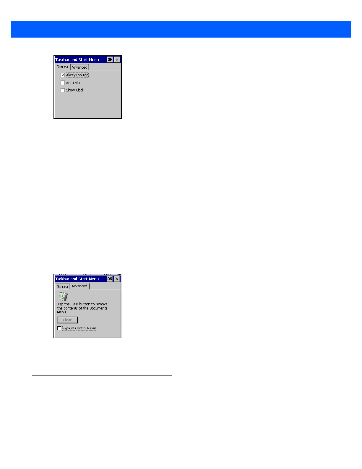
Using the Windows CE Desktop 5 - 11
Figure 5-16
2. This window provides taskbar options:
•
•
•
3. Ta p OK to save the settings and exit the window.
Taskbar and Start Menu- General Tab
Check the Always on Top checkbox to keep the taskbar on top of all other windows.
Check the AutoHide checkbox to make the taskbar disappear, touch the bottom of the display to make
the taskbar return.
Check the Show Clock checkbox to display the clock on the taskbar.
Advanced Tab
1. Tap the Advanced tab.
2. Tap t h e Clear button to delete all of the documents listed in the Start > Documents entry, see Start Button
on page 5-9. Typically this list is empty, but if there were documents in the list the Clear button would
delete them.
3. Tap t h e Expand Control Panel checkbox to display the entire contents of the Control Panel in list form,
rather than icons.
Figure 5-17
4. Ta p OK to save the settings and exit the window.
Taskbar and Start Menu-Advanced Tab
Screen Calibration
On the MC17T and MC17U, if the screen does not react properly to screen touches, the screen might require
re-calibration.
1. Select Start > Settings > Control Panel > Stylus icon > Calibration tab.
2. Tap the Recalibrate button.

5 - 12 MC17/MC17A/MC17T/MC17U Product Reference Guide
3. Carefully press and briefly hold a pointing instrument on the center of each target that appears on the
screen.
4. Repeat as the target moves around the screen, then tap the screen to continue.
Waking the MC17 Series
The wake up conditions define what actions wake up the mobile computer after it has gone into suspend mode.
The mobile computer can go into suspend mode automatically by control panel time-out settings. These
settings are configurable and the factory default settings are shown in Table 5-3. To set the wake up conditions
select Start > Control Panel > Power icon > Wakeup tab.
Table 5-3
AC power is applied. Yes
Mobile computer is inserted into a cradle. Yes
Mobile computer is removed from a cradle. Yes
Mobile computer is connected to a USB device. Yes
Mobile computer is disconnected from a USB device. Yes
A key is pressed. Yes
Trigger is pressed. Yes
Screen Tap (MC17T MC17U only) No
Wakeup Default Settings
Condition for Wakeup Automatic Time-out
Figure 5-18
Wakeup Tab

CHAPTER 6 SPECIAL CONSIDERATIONS
Introduction
The chapter provides information for:
•
Using language fonts
•
software development considerations
•
Improving battery charge time
•
Improving battery life.
Fonts
The MC17 series supports the following language fonts:
•
Simplified Chinese
•
Korean
•
Japanese
•
Greek
•
Swedish
•
Russian.
The MC17 series supports the installation of font libraries for use with application and web development.
Simplified Chinese, Korean, and Japanese font libraries are available on the Support Central Web site,
http://www.zebra.com/support
vendors. Developers should refer to Microsoft and third party vendor documentation for development and
usage details.
It should be noted that installing a language font library will not change the language configuration of the
operating system image, i.e., Windows messages will still be displayed in the language designated in the
factory supplied operating system image.
. Other standard UTF-8 encoded fonts are available from third party font

6 - 2 MC17/MC17A/MC17T/MC17U Product Reference Guide
Asian Font Installation
The Asian fonts must be installed onto the mobile computer:
1. Download the font package from Support Central.
2. Copy the language font files into the Application folder on the mobile computer:
•
.ttf, .ttc or .ac3 files
•
.reg files (required for Asian fonts)
•
.cpy files.
3. Cold boot the mobile computer.
After the mobile computer re-boots, the installed fonts are available for use.
Refer to http://msdn2.microsoft.com/en-us/library/aa911446.aspx for an explanation of font usage and
installation.
Software Development Considerations
•
Dim or turn off the backlight when the mobile computer is idle.
•
Whenever possible use default key code settings.
•
To improve performance, use RAM instead of flash memory.
•
Always lock the cradle after unlocking it.
•
Cold booting the mobile computer erases all files in RAM. Be sure to save any critical files in Application
folder, e.g.; Radio profile, time zone setting, license keys etc.
•
It is not recommended to configure the mobile computer to suspend when in the cradle. The mobile
computer will be unable to communicate with a server. Consequently, the server would be unable to
unlock the cradle or toggle the cradle LEDs.
•
User developed applications should provide a method for exiting or launching Rapid Deployment to
enable re-staging the mobile computer.
•
For detailed information on how to control the cradle LEDs and locking/unlocking the mobile computer in
the cradle, refer to the EMDK Help file.
•
Applications and servers should always treat a value of 255 (-1) as “unknown battery capacity.” Once the
battery is fully charged the 255 value goes away.
Tips for Improving Battery Charge Time
To improve battery charging time:
•
Avoid unnecessary wireless communication while the mobile computer is in the cradle.
•
Use maximum power save mode when setting up the wireless profile. (This greatly improves charging
time since the radio accounts for a large amount of power).
•
Ensure there is a good wireless signal nearby (a poor signal causes the radio to enter high power mode
much more often then normal.)

Special Considerations 6 - 3
•
Turn off display while in the cradle. If customer requires display on all the time then reducing the
brightness to minimum acceptable when in cradle will also help. See Cradle-Backlight Feature below.
Cradle-Backlight Feature
The cradle-backlight feature provides improved battery charge time when the mobile computer is placed in the
cradle. When the mobile computer is in the cradle, the backlight brightness is reduced to 25% of the maximum
brightness. When the mobile computer is removed from the cradle, the brightness returns to the default value.
This value can be using a registry setting.
NOTE By default this feature is enabled. To disable this feature, set ACINBackLightChangeEnable to
0.
Key Name: [HKEY_LOCAL_MACHINE\Drivers\BuiltIn\CradleLock]
•
Name: ACINBackLightChangeEnable
• Data Type: dword
• Description: Enable =1; Disable=0
• Default: 1
•
Name: ACINBackLightLevel
• Data Type: dword
• Description: Backlight Level in cradle: 0 to 4 (dimmest to brightest)
• Default: 0
Tips for Improving Battery Life
The MC17 series has many functions to allow server/client applications control over its power management. To
improve battery life:
•
Place the mobile computer in a Charging cradle connected to AC power when not in use.
NOTE In suspend mode, the radio cannot communicate with an AP.
•
After the customer check-out, place the mobile computer in suspend mode. This prevents the mobile
computer’s battery from discharging while sitting at a counter before being returned to the Charging
cradle. Once inserted in the cradle the mobile computer wakes up automatically.
•
When the mobile computer is not used after a time-out period place it in suspend mode. Any key press
wakes up the mobile computer. This can greatly increase battery life.
•
If the user application does not allow placing the mobile computer in suspend mode, turn off the backlight
after the time-out period.
•
Set the backlight brightness to the minimum required by the application.
•
Ensure a good wireless signal.
•
Set the wireless profile to MAX Power Save mode. If CAM mode is selected, the device does not
maximize power savings.
Running time for the MC17 series is expected to be approximately 6 to 7 hours with the following profile:

6 - 4 MC17/MC17A/MC17T/MC17U Product Reference Guide
•
2 scans/minute
•
transmitting 32K bytes of data per scan
•
75% display brightness
•
50% On/Off backlight
•
Associate to an access point (AP) with “Good” signal strength and configure the wireless profile to MAX
Power Save mode.
Changing the Power Settings
NOTE Use remote control software to navigate the operating system. See Chapter 5, Using the Windows CE
Desktop for instructions.
To set the mobile computer to turn off after a short period of non-use:
1. Select Start > Settings > Control Panel > Power icon > Power Off tab.
2. Select the On battery power: Turn off device if not used for: check box and select a value from the
drop-down list box.
3. Select OK.
Changing the Display Backlight Settings
NOTE Use remote control software to navigate the operating system. See Chapter 5, Using the Windows CE
Desktop for instructions.
To change the display backlight settings in order to conserve battery power:
1. Select Start > Settings > Control Panel > Backlight icon > Battery Power tab.
2. Select the On battery power: Disable backlight if not used for: check box and select a value from the
drop-down list box.
3. Select the Brightness tab.
4. Select the Disable backlight check box to completely turn off the display backlight.
5. Use the slider to set the brightness of the backlight. Set it to a low value to save battery power.
6. Select OK.

Special Considerations 6 - 5
MC17U Non-touch Support
The MC17U is a touch screen device. The touch screen can be disabled by adding a registry setting.
Using a registry editor, navigate to the following:
[HKEY_LOCAL_MACHINE\HARDWARE\DEVICEMAP\TOUCH]
Create the following key:
"DriverName"=" "
After creating the registry key, warm boot the MC17U.
To re-enable the touch screen, use a registry editor to delete the key created above.

6 - 6 MC17/MC17A/MC17T/MC17U Product Reference Guide

CHAPTER 7 POCKET BROWSER
Introduction
This feature-rich, mobile application development tool is designed to allow Web developers to rapidly create
robust mobile applications that can include a wide range of advanced data capture capabilities. Whether you
want to streamline your warehouse, delivery or service operations, or enable more robust asset tracking or
visibility, Pocket Browser will help you get your enterprise mobility solution up and running faster — and more
cost efficiently.
The Pocket Browser Developer Help provides detailed information about how to use each feature of the
browser. Each feature includes a sample for you to use, however, please be aware that the sample does not
necessarily show the only way to implement each feature.
Pocket Browser enables developers and integrators to provide advanced Web-based solutions to select
Microsoft® Windows Mobile and Windows CE mobile computers. PocketBrowser makes the most of
enterprise-level applications while speeding up development time and reducing costs. With it, making the
transition to web-based solutions is now fast, easy and affordable - especially in high-volume mobile
environments.
Pocket Browser is a software tool that extends the core rendering engine functionality of Microsoft PocketIE or
Microsoft IE with Zebra application programming interfaces (APIs). It provides interfaces to the mobile
computer hardware and features using meta tags and Microsoft ActiveX® components designed specifically
for Zebra systems. Pocket Browser offers easy integration with bar code scanners, RFID readers and other
peripherals such as printers and magnetic stripe readers (MSR) for complete transaction processing.
Sample Application
The mobile computer comes with a sample PocketBrowser applications factory-installed. The sample
application is accessible from the App Launcher menu.
From the App Launcher menu, select SPB. The PocketBrowser window appears.

7 - 2 MC17/MC17A/MC17T/MC17U Product Reference Guide
Battery Status Indicator
Wireless Signal Strength Indicator
ZEBRA
Figure 7-1
The sample PocketBrowser provides the following information:
•
•
•
•
The three buttons at the bottom of the screen:
•
•
•
Sample PocketBrowser Screen
Battery level status bars
WLAN signal strength status bars
Battery Details:
• Battery strength in percentage
• Whether in cradle of not
WLAN details:
• ESSID name
• Signal
• IP Address of the mobile computer
• MAC address of the mobile computer.
Unlock/Lock - Unlocks and locks the mobile computer into the cradle.
LEDS - Illuminates the cradle LEDs
Quit - Exits the sample PocketBrowser application.

CHAPTER 8 CRADLE INSTALLATION
Introduction
A system is comprised of a family of hardware devices interconnected through a WLAN radio backbone to the
retail establishment’s server(s). The hardware devices are the MC17 mobile computers, charging cradles (one
per MC17 mobile computer), power supplies, and cables. A dispenser typically refers to a piece of furniture
which has mounted to it the Charging cradles, their power supplies, and cables.
Customers (retail establishments) design their own dispensers to meet their particular floor space and display
requirements. The information in this chapter should help a customer to design a dispenser and to understand
the installation requirements.
Installation of the Charging Cradle
Removing the Front Cover
To remove the front cover:
1. Loosen two captive screws securing the front cover to the base.
Figure 8-1
2. Pull front cover away from base and then lift out of the base.
Remove Screws

8 - 2 MC17/MC17A/MC17T/MC17U Product Reference Guide
Alignment Holes
Figure 8-2
Cover Removal
Mounting the Cradle
The Charge cradle contains mounting holes in the back housing so that it can be bolted to supporting furniture.
In addition, it come with plugs and a variety of cable routing outlets. Cable outlets not used can be concealed
with the plugs provided. Figure 8-3 provide the information required to design correct mounting holes for the
charge cradles.

Cradle Installation 8 - 3
Mounting holes (4)
20.5 mm
(0.80”)
86 ± 0.2 mm
(3.39 ± 0.01”)
10 mm
(0.40”)
127 mm ± 0.4 mm
(5.0” ± 0.02”)
154 ± 0.2 mm
(6.06” ± 0.01”)
271.8 mm ± 0.7 mm
(10.70” ± 0.03”)
Figure 8-3
Cradle Mounting Template

8 - 4 MC17/MC17A/MC17T/MC17U Product Reference Guide
Depth of cradle:
99 mm
(3.9”)
Power Cable 25-66420-01R
Power Supply 50-14000-241R
(inside Decorative Housing)
Figure 8-4
Overall Depth of Cradle
Wiring
NOTE During installation ensure all interconnect cables are fully enclosed within the power supply or cradle enclosure.
1. Install power supply, including AC line cord and power cable, into Decorative Housing.
Figure 8-5
Connecting Power Supply

Cradle Installation 8 - 5
Interconnect Cable 25-66431-01R
2. Insert power cable through a cable outlet of cradle back housing.
3. Plug connector into power connector on printed circuit board.
4. If more than one cradle, connect the interconnect cable from the first cradle to the second cradle.
Figure 8-6
5. Use plugs to cover un-used cable outlets.
Figure 8-7
Daisy-Chaining Cradles
Cable Hole Plug Installation
Assembly
6. Replace cover.
7. Secure cover with screws.

8 - 6 MC17/MC17A/MC17T/MC17U Product Reference Guide
Figure 8-8
8. Insert bar code target cover.
9. Push target cover into front cover until it snaps into place.
Figure 8-9
Replace Cover
NOTE Do not install the target cover until you are sure that you do not need to remove the front cover again.
Replace Target Bar Code Cover
Cradle Location Bar Code
Note that a cradle location bar code can be mounted on the underside of the target plastic cover.

System Cabling
There are some general limitations that must be taken into account when designing a dispenser and ordering
hardware elements of a system:
•
No more than six Charging cradles can be powered off of one power supply and power cable
25-66420-01R.
•
No more than 12 Charging cradles can be powered off of one power supply and “Y” power cable
25-67592-01R.
•
No more than six Charging cradles can be powered off each leg of the “Y” power cable.
•
A power supply cable runs from the power supply to one or two Charging cradles.
•
Cradle interconnection cables run between each successive cradle in the chain.
•
The power supply is air cooled, and as such expects some circulation of fresh air around it. Do not
enclose it in a small airtight enclosure.
•
Power supplies must be mounted in their natural, landscape orientation. They contain fans and their
vents must allow for the free flow of air.
Cradle Installation 8 - 7
•
Power supplies should be mounted either above or below dispensers and entrance heads. Mounting of
power supplies to the right or left is not preferred.
•
When laying out furniture, cable routing should be as direct as possible. Routing should follow vertical
and horizontal runs through the modules. As part of each power supply that is shipped is a set of labels
numbered 1 through 12. These labels are to be used to track the number of loads on a particular supply.
Each label is affixed to the cradle interconnection cable when a cradle is added to the daisy chain. When
all labels are used, the supply is fully loaded.
Figure 8-10 shows how the maximum number of Charging cradles can be cabled to a power supply using
power cable 25-66420-01R.
Figure 8-11 shows how the maximum number of Charging cradles can be cabled to a power supply using the
“Y” power cable 25-67592-01R. Note that there are only six cradles per leg of the power supply cable, and only
12 cradles in total.
Figure 8-10
Maximum Number of Charge Cradles per Power Supply

8 - 8 MC17/MC17A/MC17T/MC17U Product Reference Guide
Figure 8-11
Maximum Number of Charge Cradles per Power Supply with “Y” Power Cable

Mounting the Power Supply Housing
(View from Inside Housing)
The depth of the fully-assembled power supply decorative housing is 81.23 mm (3.198”).
10 mm
(0.394”)
38.1 mm
(1.50”)
135.9 mm
(5.35”)
115.9 mm
(4.562”)
254.0 mm
(10.00”)
68.4 mm
(2.693”)
109.4 mm
(4.307”)
The power supply can be housed in a plastic housing, p/n PSS-3PS04-00R, to match the Charging cradles and
hide bare power supplies and cables. This section provides the information required to mount the plastic
housing.
NOTE The power supply should be mounted in landscape orientation.
UP
Cradle Installation 8 - 9
Figure 8-12
1. Feed cables through access holes in bottom housing.
2. Plug connectors into power supply.
3. Place power supply into bottom housing.
4. Place two mounting brackets over power supply and secure each mounting bracket with two screws.
Power Supply Housing Mounting Template

8 - 10 MC17/MC17A/MC17T/MC17U Product Reference Guide
Power Supply Cable
Output Cable
Mounting bracket
Screws
Bottom Housing
Top Housing
Screws
Figure 8-13
5. Align top housing over bottom housing and secure using six screws.
Figure 8-14
Power Supply Assembly
Top Housing Installation

CHAPTER 9 APPLICATION DEPLOYMENT
Software Installation on Development PC
To develop applications to run on the mobile computer, use one or all of the following:
•
Enterprise Mobility Developer Kit (EMDK) for C
•
Enterprise Mobility Developer Kit (EMDK) for .NET
•
Enterprise Mobility Developer Kit (EMDK) for Java
•
Enterprise Mobility Developer Kit (EMDK) for Pocket Browser
•
Windows CE Platform SDK for MC17xxc50
•
Device Configuration Package (DCP) for MC17xxc50.
Refer to the Developer Guide, p/n 72E-71161-xx, for detailed information on the EMDKs.
The Windows CE Platform SDK for the MC17xxc50 is used in conjunction with the EMDK for C to create
Windows CE applications for the MC17xxc50 mobile computer. The Platform SDK installs a new Windows CE
device type and its associated libraries onto the development PC.
The Device Configuration Package (DCP) is required to create and download hex images that represent flash
partitions to the mobile computer. The DCP includes the user documentation, flash partitions, Terminal
Configuration Manager (TCM) and the associated TCM scripts.
Device Configuration Package
To install the DCP for MC17xxc50:
1. Download the DCP from the Support Central web site, http://www.zebra.com/support:
a. On http://www.zebra.com/support, select Software Downloads.
b. Select Mobile Computers and then select MC17.
c. Select the Device Configuration Package (DCP).
d. Save the .exe file to the development computer.
2. Locate the .exe file on the development computer, double-click the file, and follow the install screen
prompts.

9 - 2 MC17/MC17A/MC17T/MC17U Product Reference Guide
3. Once installed, access the major components of the DCP from the Device Configuration Package (DCP)
for MC17xxc50 program group of the Windows Start Menu.
Platform SDK
Different Platform SDKs are required for the Microsoft® Windows CE 5.0 Professional and Microsoft®
Windows CE 5.0 Core platforms. To download and install the appropriate Platform SDK:
1. Download the appropriate Platform SDK from the Support Central web site, http://www.zebra.com/support:
a. On http://www.zebra.com/support, select Software Downloads.
b. Select Mobile Computers and then select MC17.
c. Select the Platform SDK.
d. Save the .exe file to the development computer.
2. Run the file and follow the screen prompts to install.
Enterprise Mobility Developer Kits
To install an EMDK:
1. Download the EMDK from the Support Central web site, http://www.zebra.com/support:
a. On http://www.zebra.com/support, select Developer Downloads and sign in.
b. Select Mobile Computers and then select MC17.
c. Select the latest version of the Enterprise Mobility Developer Kit.
d. Download the .exe file to the development computer.
2. Double-click the executable file and follow the install screen prompts.
Installing Other Development Software
Developing applications for the mobile computer may require installing other development software such as
application development environments on the development PC. Follow the installation instructions provided
with this software.

Deployment
With the appropriate accessory, software, and connection, the mobile computer can share information with the
host device. This section provides information about installing software and files on the mobile computer.
Download/install software using:
•
ActiveSync
•
IPL.
ActiveSync
Use ActiveSync to copy files from a host computer to the mobile computer.
1. Ensure that ActiveSync is installed and that a partnership has been created, see Chapter 4, ActiveSync.
2. Connect the mobile computer to the host computer using the Charging cradle, see Chapter 8, Cradle
Installation for connection information.
3. On the host computer, select Start > Programs > ActiveSync.
Application Deployment 9 - 3
4. Select Explore.
Figure 9-1
5. Double-click the folder to expand the contents of the folder.
ActiveSync Explorer

9 - 4 MC17/MC17A/MC17T/MC17U Product Reference Guide
Figure 9-2
6. Use Explorer to locate the host computer directory that contains the file to download. Tap that directory in
the left pane to display its contents in the right pane.
7. Drag the desired file(s) from the host computer to the desired mobile device folder.
•
•
My Pocket PC Contents
Program Files folder: files stored in this folder are discarded after a cold boot.
Application folder: files stored in this folder are retained after a cold boot.
IPL
Use IPL to download files onto the mobile computer, to download customized flash file system partitions to the
mobile computer and load hex files to the flash memory of the mobile computer.
There are two types of updates supported by the mobile computer: partitions and files. The file system used by
the mobile computer is the same as the file system used on a desktop computer. A file is a unit of data that can
be accessed using a file name and a location in the file system. When a file is replaced, only the contents of the
previous file are erased. The operating system must be running for a file to be updated, so the IPL cannot
perform individual file updates as it is a stand-alone program that does not require the operating system to be
running.
A typical partition is a group of files, combined into a single “partition” that represents a specific area of storage.
Examples of partitions are the flash file systems such as Platform or Application. (Using the desktop computer
comparison, these partitions are roughly equivalent to a C: or D: hard disk drive.) In addition to the “hard disk”
partitions, some partitions are used for single items such as the operating system, monitor, or splash screen.
(Again using a desktop computer comparison, these partitions are roughly the equivalent of the BIOS or
special hidden system files.) When a partition is updated, all data that was previously in its storage region is
erased - i.e. it is not a merge but rather a replacement operation. Typically, the operating system is not running
when partitions are updated, so IPL can perform partition updates.
Partition images for selected partitions can be created by TCM. All partition images suitable for use by IPL are
in hex file format for transfer by TCM from the development computer to the mobile computer.
Upgrade requirements:
•
The hex files to be downloaded (on development computer)
•
A connection from the host computer and the mobile computer (either serial or wireless)

•
TCM (on development computer) to download the files.
Once these requirements are satisfied, the mobile computer can be upgraded by invoking IPL and navigating
the menus. See Sending the Hex Image Using IPL on page 9-10 for procedures on downloading a hex file to
the mobile computer.
Creating Hex Images
Terminal Configuration Manager (TCM) is an application used to customize flash file system partitions for the
mobile computer. The most common use is to create an application partition hex file that contains the
customer's application. TCM can also be used to load hex files to the flash memory of the mobile computer.
The program resident on the mobile computer that receives the hex file and burns it to the flash memory is
called Initial Program Loader (IPL).
The customization of partitions is controlled by TCM scripts. The scripts contain all of the necessary
information for building an image. The script is a list of copy commands specifying the files to copy from the
development computer to the partition.
TCM works with a pair of directory windows, one displaying the script and the other displaying the source files
resident on the development computer. Using standard windows drag and drop operations, files can be added
and deleted from the script window.
Application Deployment 9 - 5
The DCP for MC17xxc50 includes scripts used by Zebra to build the standard factory installed Platform and
Application partitions provided on the mobile computer. The standard Platform partition contains drivers while
the Application partition contains demo applications and optional components. The standard TCM scripts can
be found in the following folder: C:\Program Files\Symbol Device Configuration Packages\MC17xxc50
v1.0\TCM Scripts.
NOTE Before creating a script to build a hex image, identify the files required (system files, drivers, applications,
etc.) and locate the files’ source directories to make the script building process easier.
The required processes for building a hex image in TCM include:
•
Starting TCM
•
Defining script properties
•
Creating the script for the hex image
•
Building the image
•
Sending the hex image
•
Creating a splash screen
•
Flash storage.
Starting Terminal Configuration Manager
Click the Windows Start menu TCM icon (Device Configuration Packages, MC17xxc50) to start TCM. The
TCM window appears displaying two child windows: Script1 and File Explorer. The Script1 window contains
a newly created script and the File Explorer window contains a file explorer view used for selecting files to be
placed in the script.

9 - 6 MC17/MC17A/MC17T/MC17U Product Reference Guide
Figure 9-3
The following table lists the components of the TCM window.
Table 9-1
Icon Component Function
TCM Startup Window
TCM Components
Script Window Displays the files to be used in the creation of the partition(s).
File Explorer Window Used to select the files to be added to the script.
Create button Create a new script file.
Open button Open an existing script file.
Save button Save the current script file.
Large icons button View the current script items as large icon.
Small icons button View the current script items as small icon.
List button View the current script items as a list.
Details button View the current script items with more details.
About button Display version information for TCM.
Properties button View/change the current script properties.

Application Deployment 9 - 7
Table 9-1
TCM Components (Continued)
Icon Component Function
Build button Build the current script into a set of hex files.
Check button Check the script for errors (files not found).
Send button Download the hex image to the vehicle computer.
Tile button Arrange the sub-windows in a tiled orientation.
Build and Send Build the current script into a set of hex images and send the hex
images to the vehicle computer.
Preferences button View/change the global TCM options.
Defining Script Properties
Before a script is created, the script properties must be defined. This defines the type of mobile computer, flash
type, number of disks being created and the memory configuration of each disk partition.
To define the script properties:
1. Select the Script window to make it active.
2. Click the Properties button. The Script Properties window > Partition Data tab appears.
Figure 9-4
3. In the Terminal drop-down list, select the mobile computer type.
4. Use the default Flash Type.
Script Properties Window - Partition Data Tab
5. In the Disks drop-down list, select the number of disk partitions to create.
6. Select the (memory) Size for each partition. Note that adding space to one disk. partition subtracts it from
another.
7. In the Access drop-down list for each disk partition, determine and select the Read/Write access option.

9 - 8 MC17/MC17A/MC17T/MC17U Product Reference Guide
8. Click the Options tab. The Script Properties window Options tab appears.
Figure 9-5
9. Set the paths for the Script File, Flash File and Hex File Build.
10. Click OK.
Script Properties Window - Options Tab
Creating the Script for the Hex Image
On start-up, TCM displays the TCM window with the Script1 window and File Explorer window pointing to the
following directory:
\Program Files\Symbol Device Configuration Packages\MC17xxc50\v0.1\TCMScripts\
The Script1 window directory pane displays two partitions: Platform and Application. Depending on the type of
flash chip, the number of partitions may change. Files can be added to each of the partitions. TCM functionality
includes:
•
Opening a new or existing script file
•
Copying components to the script window
•
Saving the script file.
Opening a New or Existing Script
A script file can be created from scratch or based on an existing script file. Click Create to create a new script
or click Open to open an existing script (for example, a script provided in the DCP for MC17xxc50). If an
existing script is opened and changes are made, saving the changes overwrites the original script. To use an
original or Zebra supplied standard script as a base and save the changes in a new script, use the Save As
function to save the script using a different file name.
Updating TCM 1.X Scripts
Script files that were created with older versions of TCM can be upgraded to TCM 2.0 scripts. Click Open to
open an existing script created with an older version of TCM. The Conversion window appears automatically.
Copying Components to the Script
Script contents are managed using standard file operations such as New Folder, Delete and Rename. Items
can be added to the script by clicking files and folders in the File Explorer window and dragging them to the
 Loading...