

Page 1

Page 2

WhereLAN III User Guide
© 2011 Zebra Enterprise Solutions Corp.
The copyrights in this manual and the software and/or firmware and hardware described therein are owned by Zebra
Enterprise Solutions Corp. and Zebra’s licensors. Unauthorized reproduction of this manual or the software and/or
firmware may result in imprisonment of up to one year and fines of up to $10,000 (17 U.S.C.506). Copyright
violators may be subject to civil liability.
ZEBRA and the Zebra logo are registered trademarks of ZIH Corp. WhereNet is a registered trademark of Zebra
Enterprise Solutions Corp. All rights reserved worldwide.
All other brand names, product names, or trademarks belong to their respective holders.
Proprietary Statement
This manual contains proprietary information of Zebra Technologies Corporation and its subsidiaries. It is intended
solely for the information and use of parties operating and maintaining the equipment described herein. Such
proprietary information may not be used, reproduced, or disclosed to any other parties for any other purpose without
the express, written permission of Zebra Technologies.
Product Improvements
Continuous improvement of products is a policy of Zebra Technologies. All specifications and designs are subject to
change without notice.
Liability Disclaimer
Zebra Technologies takes steps to ensure that its published Engineering specifications and manuals are correct;
however, errors do occur. Zebra Technologies reserves the right to correct any such errors and disclaims liability
resulting therefrom.
Limitation of Liability
In no event shall Zebra Technologies or anyone else involved in the creation, production, or delivery of the
accompanying product (including hardware and software) be liable for any damages whatsoever (including, without
limitation, consequential damages including loss of business profits, business interruption, or loss of business
information) arising out of the use of, the results of use of, or inability to use such product, even if Zebra
Technologies has been advised of the possibility of such damages. Some jurisdictions do not allow the exclusion or
limitation of incidental or consequential damages, so the above limitation or exclusion may not apply to you.
2 D1675 rev B May 2011
Page 3
WhereLAN III User Guide
_____________
_____________
____________
Note
____________
____________
____________
Typographical Conventions
Warnings call attention to a procedure or practice that could result in
personal injury if not correctly performed. Do not proceed until you fully
understand and meet the required conditions.
Cautions call attention to an operation procedure or practice that could
damage the product, or degrade performance if not correctly performed.
Do not proceed until understanding and meeting these required
conditions.
Notes provide information that can be helpful in understanding the
operation of the product.
May 2011 D1675 rev B 3
Page 4

WhereLAN III User Guide
Revision
Description of Changes
Date
Approved
A B Initial Release
Per ECO C02532
10/20/10
05/09/11
GLC
GLC
Document Revision History
4 D1675 rev B May 2011
Page 5

WhereLAN III User Guide
Table of Contents Page
1 DOCUMENT OVERVIEW ................................................................................................. 7
2 PRODUCT DESCRIPTION AND FEATURES ................................................................ 7
3 PRODUCT SPECIFICATIONS .......................................................................................... 8
3.1 MECHANICAL ................................................................................................................... 8
3.2 ELECTRICAL ..................................................................................................................... 8
3.3 ENVIRONMENTAL ............................................................................................................. 8
3.4 EXTERNAL CONNECTIONS ................................................................................................ 9
4 ACCESSORIES .................................................................................................................. 10
5 CONFIGURATION & CONTROL .................................................................................. 11
5.1 LOCATION SENSOR SELF-BOOT ..................................................................................... 11
5.2 LOCATION SENSOR INTERFACE ...................................................................................... 11
5.3 LOCATION SENSOR MAC/ IP ADDRESS CONFIGURATION .............................................. 12
5.4 WLAN CLIENT CONFIGURATION (LOS-5000-00AB ONLY) .......................................... 16
6 INSTALLATION AND MOUNTING .............................................................................. 17
6.1 SAFETY AND INSTALLATION WARNINGS AND CAUTIONS ............................................... 17
6.2 MOUNTING ..................................................................................................................... 18
6.3 3/8THS THREADED ROD ................................................................................................. 20
6.4 POLE MOUNT KIT .......................................................................................................... 22
7 ANTENNAS......................................................................................................................... 28
7.2 VERTICAL DIVERSITY MOUNTING ................................................................................. 31
7.3 ANTENNA WLAN 802.11 .............................................................................................. 34
8 CABLING ............................................................................................................................ 35
8.1 POWER, AC ................................................................................................................... 36
8.1 ETHERNET ...................................................................................................................... 37
8.2 TIMING CABLE INTERCONNECTION GUIDELINES ............................................................ 37
8.3 LOCATION SENSOR OPERATIONAL VERIFICATION ......................................................... 43
9 REGULATORY INFORMATION ................................................................................... 45
9.1 RF NOTICE ..................................................................................................................... 45
9.2 EU COMPLIANCE INFORMATION (LOS-5000-00AA & LOS-5000-00AB) .................... 45
APPENDIX A: LOS-5000 EFFECTIVE PROJECTED AREA (EPA) ................................. 47
APPENDIX B: LOS-5000 WEIGHT ....................................................................................... 48
May 2011 D1675 rev B 5
Page 6

WhereLAN III User Guide
Table of Figures Page
Figure 1 Example of LOS-5000-00AB Label ............................................................................... 13
Figure 2 Safety and Warnings ....................................................................................................... 17
Figure 3 Mounting Points ............................................................................................................. 18
Figure 4 Safety Lanyard................................................................................................................ 19
Figure 5 Threaded-Rod ................................................................................................................. 20
Figure 6 Safety Lanyard................................................................................................................ 21
Figure 7 Pole Mount Kit ............................................................................................................... 22
Figure 8 Bracket Mount ................................................................................................................ 23
Figure 9 Retaining Bolts ............................................................................................................... 24
Figure 10 Location Sensor Mounted ............................................................................................. 25
Figure 11 Pole mount on Pole ....................................................................................................... 26
Figure 12 Location Sensor on Pole ............................................................................................... 27
Figure 13 Office Omni .................................................................................................................. 28
Figure 14 All Weather Omni ........................................................................................................ 28
Figure 15 Minimum clearance to metallic structures .................................................................... 29
Figure 16 Corner mount industrial application ............................................................................. 29
Figure 17 Office omnidirectional in corridor ................................................................................ 30
Figure 18 Vertical Diversity 5ft, ................................................................................................... 32
Figure 19 Vertical Diversity +11ft. ............................................................................................... 33
Figure 20 Vertical Diversity Connections .................................................................................... 34
Figure 21 Location Sensor Connections ....................................................................................... 35
Figure 22 Drip Plug ...................................................................................................................... 35
Figure 23 Timing cable wiring pin out ......................................................................................... 38
Figure 24 Timing Cable Trim ....................................................................................................... 39
Figure 25 Timing Cable Jacket ..................................................................................................... 39
Figure 26 Timing Cable Trim ....................................................................................................... 40
Figure 27 Timing Cable Pull Jacket.............................................................................................. 40
Figure 28 Timing Cable Crimp ..................................................................................................... 41
Figure 29 Test setup for CAT5 cable using Fluke 620 ................................................................. 42
Figure 30 Correct readout when testing 2 pair cable. ................................................................... 43
Figure 31 Location Sensor LED indicators ................................................................................... 43
6 D1675 rev B May 2011
Page 7

WhereLAN III User Guide
1 DOCUMENT OVERVIEW
This document describes the basic configuration and recommendations on
physical installation of the WhereLAN III product, which is part of the
Location Sensor product line. The site design and placement is detailed in the
Location Sensor Placement Guide D0406 and WhereLAN III Installation
Guide 26913.
2 PRODUCT DESCRIPTION AND FEATURES
The WHERELAN III is the next generation of WhereLAN products that
receives the signals transmitted by WhereTags (ISO 24730-2), and provides
data to the Location Algorithm processor. The WhereLAN III Location
Sensor has improved performance and uses less power than the previous
WhereLAN Location Sensor. The “received tag blinks” are decoded, time
stamped, and routed to a PC or ZLA (Zebra Location Appliance) for
additional processing. The locate algorithm running on the PC or ZLA
calculates the tag position based on the time stamps of multiple Location
Sensors, and reports that position to the database where it is displayed by
Resource Manager.
There are three base WhereLAN III configurations:
LOS-5000-00AA(Wired Ethernet, POE 802.3af compliant)
LOS-5000-00AB (with 802.11b/g Wireless LAN Client, POE 802.3af
Compliant)
LOS-5000-01AA (no embedded transmissions, Wired Ethernet, POE
802.3af Compliant)
Both the LOS-5000-00AA and LOS-5000-00AB configurations also include a
low power an embedded transmitter, which complies with the ISO 24730-2
standard, is used to distribute configuration data, health, and timing signals to
other Location Sensor units.
The embedded transmitter uses channels, both left and right, to transmit and
receive, which is not compatible with the legacy LOS/LAP 4000 series
WhereLAN products. However, by default the WHERELAN III will be
shipped in G2 emulation mode. During site launch with System Builder, the
user will be able to select full WHERELAN III mode to take advantage of the
enhanced features, provided it is not being used to replace the WhereLAN
infrastructure. Note: The LOS-5000-01AA has this embedded transmitter
function disabled.
May 2011 D1675 rev B 7
Page 8

WhereLAN III User Guide
Size:
10.3 x 1.7 x 12.0
261 x 43 x 305
in (HxDxW)
mm
Weight:
7.0
3.2
Lbs
Kg
Voltage:
36 to 57
48V nominal
Vdc
Current:
.350 (max)
Amps
Power Dis.:
13.0 (max)
Watts
Power:
Can be powered by a Zebra
approved, limited AC to DC power
supply or Power Over Ethernet
(POE). See Accessories List.
Operating Temp.1:
Storage Temperature:
-40 to +60
-40 to +70
ºC
Ingress Protection:
54
IP
Humidity
5 to 95%
Non-condensing
3 PRODUCT SPECIFICATIONS
3.1 Mechanical
3.2 Electrical
3.3 Environmental
1
See power supply limits
8 D1675 rev B May 2011
Page 9

WhereLAN III User Guide
Antenna (2):
MCX (Jack)
DC Power:
2.5 ID/ 5.5 OD mm (Jack)
Opt. WiFi Antenna:
SMB (Jack)
Ethernet:
RJ45 (Jack) 10/100 and 802.3af POE
Timing (3):
RJH (4-wire telephone handset Jack)
3.4 External Connections
The Location Sensor utilizes standard 10/100 802.3 Ethernet connectivity via
Cat-5 cables. The WhereLAN III must be wired to a nearby hub, which is in
turn connected to the network containing the database CPU. The maximum
Ethernet cable run is 328 ft (100 m). If additional distance is required, hubs,
repeaters, and fiber (with 10BaseT converters) can be used to extend the
distance. Refer to IEEE guidelines for Ethernet cabling. It is also compliant
with 802.3af POE standard.
May 2011 D1675 rev B 9
Page 10

WhereLAN III User Guide
Accessories
Model Number
All Weather Omni Antenna
(standard)
AK-210-10
Office Omni Antenna1 (indoor
only)
AK-110-10
DC power cable extender, 50 ft,
Plenum Rated (Indoor Only)
DC power cable extender, 50ft.,
Outdoor Rated.
PX-010-00
PX-050-00
Power Over Ethernet injector
EP-025-00
Power Supply
PS-040-00
Pole Mount Kit:
LAN Antenna Kit
LAN Antenna Indoor 2.2dBi
LAN Antenna Omni 5.2dBi
LAN Antenna Directional
13.5dBi
RM-510-00
TBD
AK-170-00
AK-151-00
AK-153-00
4 ACCESSORIES
The accessories indicated below are required to complete the installation of
the Location Sensor. Ordering information is supplied where applicable.
Note: Not all accessories are globally available. Check with local sales representative
regarding availability.
10 D1675 rev B May 2011
Page 11

WhereLAN III User Guide
____________
Note
____________
____________
Note
____________
5 CONFIGURATION & CONTROL
5.1 Location Sensor Self-Boot
Upon power up, the Location Sensor (LS) executes a self boot process. The
boot process takes between 45 to 60 seconds. If a fault occurs during the boot
process, the unit may reset and restart the boot process. During that process,
the four LEDs blink in a sequence to indicate the current stage of the power
up boot process. Once the boot process is complete, the LEDs revert to their
standard functions indicating power/health, tag status, Ethernet, and WLAN.
5.2 Location Sensor Interface
After the Location Sensor has completed its boot process, it is possible to
communicate with the unit via the following methods.
Do not attempt to communicate with the Location Sensor until it has
completed the first stage of the boot process (i.e., left LED is solid). Doing so
will stop the boot process. The unit must be reset to clear this condition.
These units are configured using:
Telnet/SSH via Ethernet (preferred)
iSensor (Sensor Analyzer)
WhereWand
Hyperterminal (or any terminal emulation software) via serial port
Telnet/SSH is the preferred method of communicating with the Location
Sensor, once installed. Use the HyperTerminal for initial setup before
being installed on a network for setting static IP addresses, if DHCP is not
used.
Telnet/SSH via Ethernet
Communication Parameters:
10/100 Mb/s
Cat-5 cable/ RJ-45 plug.
To connect via telnet, open a DOS command prompt window and type
telnet <IP address>,where the IP address is iSensor (Sensor Analyzer)
May 2011 D1675 rev B 11
Page 12

WhereLAN III User Guide
____________
Note
____________
Hyperterminal via Serial Port
Communication Parameters:
Null-modem cable, 9-pin female to 9-pin female
19200 baud
8 data bits, 1 stop bit, no parity, no hardware flow control
Hyperterminal is used in only two instances. The first is for initial
configuration where the Location Sensor has been configured for DHCP, but
there is no DHCP server available. The second instance is if a fault occurs
during the first stage of the boot process, or if visibility to the boot process is
needed for debugging installation problems.
5.3 Location Sensor MAC/ IP Address Configuration
Location Sensors communicate over an Ethernet interface using TCP/IP. For
the LOS-5000-00AB, both the Location Sensor and the embedded Client Card
must be independently configured with their own unique IP addresses. The IP
address of each LS must be recorded and entered into the ZES site file, which
contains the configuration information for each LS, including its location, and
MAC address.
Failure to configure the Location Sensor prior to operation may result in
an inoperative unit.
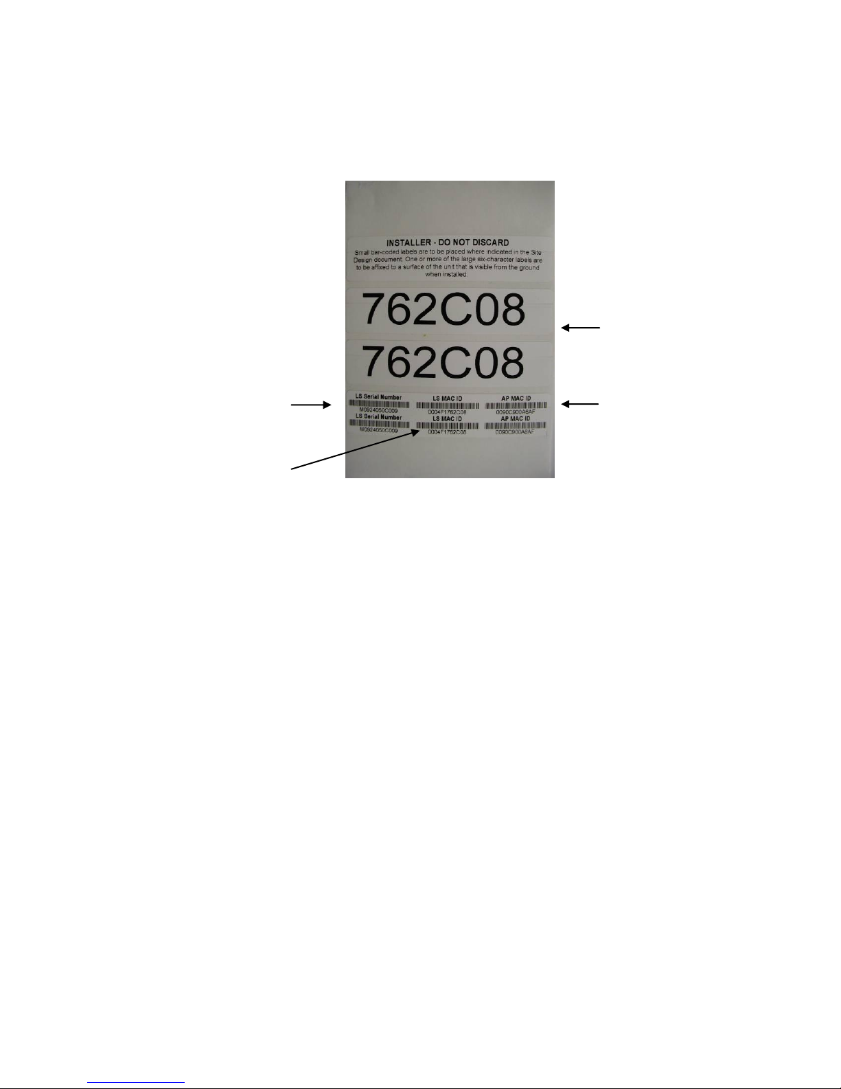
Each Location Sensor is shipped with a label set containing one label (Figure
1) with the bar coded MAC address of the Location Sensor and Wifi Client
and three labels with the last six characters of the Location Sensor’s MAC
address in large type. Ensure that the label is correct by matching the MAC
address(es) on the loose label set with the MAC address(es) listed on the back
of the Location Sensor. Place the loose bar code label in the site design
document where indicated, and place one or more of the large type, six
character labels on the exterior of the Location Sensor in positions that are
visible after installation.+
12 D1675 rev B May 2011
Page 13
WhereLAN III User Guide
Last 6 LS
MAC digits
Wifi Client
MAC Address
Location Sensor
MAC Address
Location Sensor
Serial Number
____________
Note
____________
____________
Note
____________
The MAC address label must be clearly marked on the exterior of the
Location Sensor housing in a position visible after installation.
`
Figure 1 Example of LOS-5000-00AB Label
Like other network equipment, the Location Sensor IP address(es) must be set
to a predetermined address. While there is no restriction to the IP address, it
must match the address in the Site file for that particular Location Sensor.
The IP address(es) can be static assigned, or dynamically assigned via DHCP.
If assigned through DHCP, the DHCP server must contain the MAC address
and corresponding IP address for each of the Location Sensors (and WLAN
Client).
For networks utilizing DHCP, the MAC addresses of the Location Sensor
and Wifi Client (LOS-5000-00AB only) must be entered in the DHCP
server.
May 2011 D1675 rev B 13
Page 14
WhereLAN III User Guide
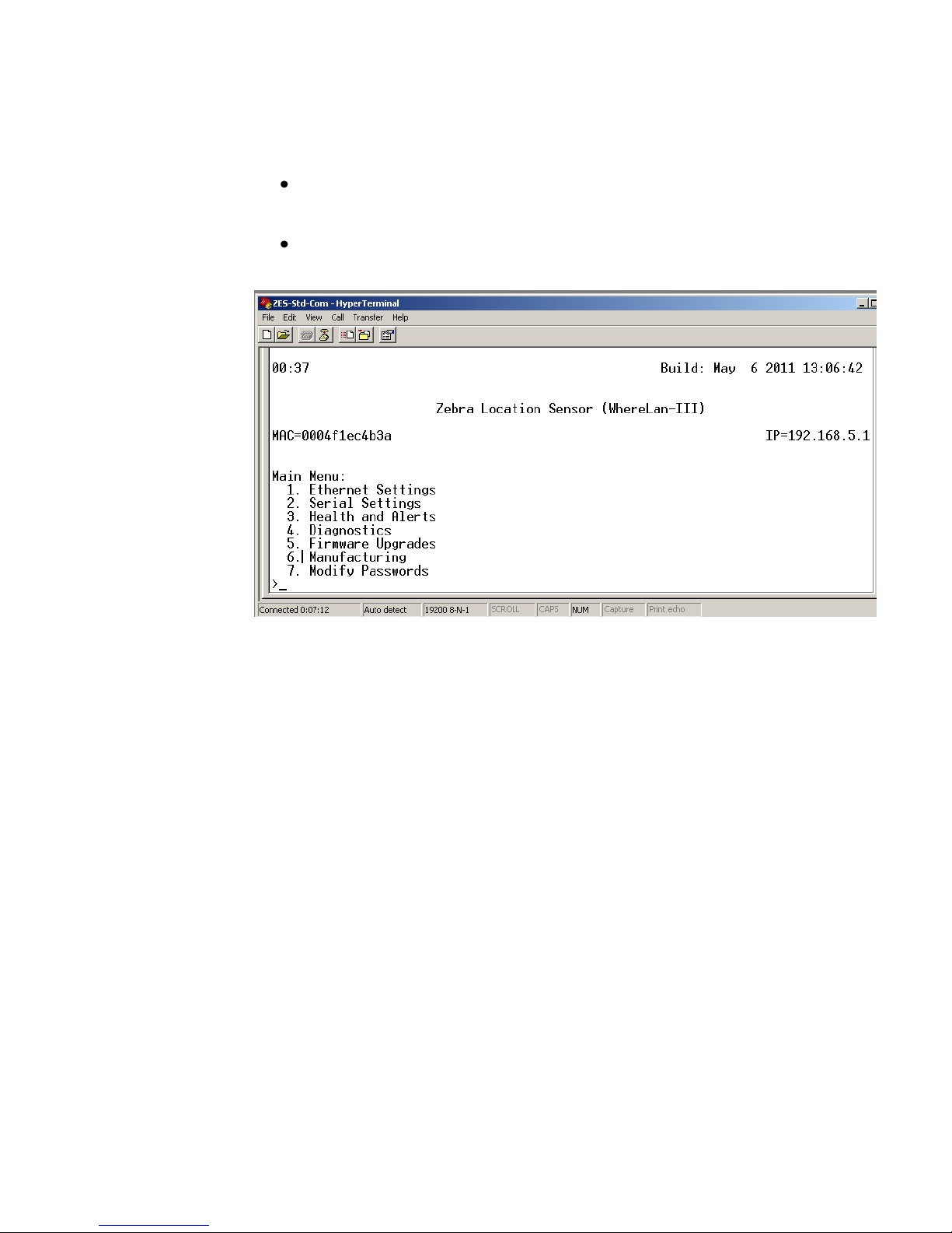
To configure the IP address of the Location Sensor:
Note the following configuration examples are done thru HyperTerminal.
Connect to the Location Sensor using Telnet (preferred), or
HyperTerminal.
Select 1 and confirm the unique MAC address for the Location Sensor.
14 D1675 rev B May 2011
Page 15
WhereLAN III User Guide
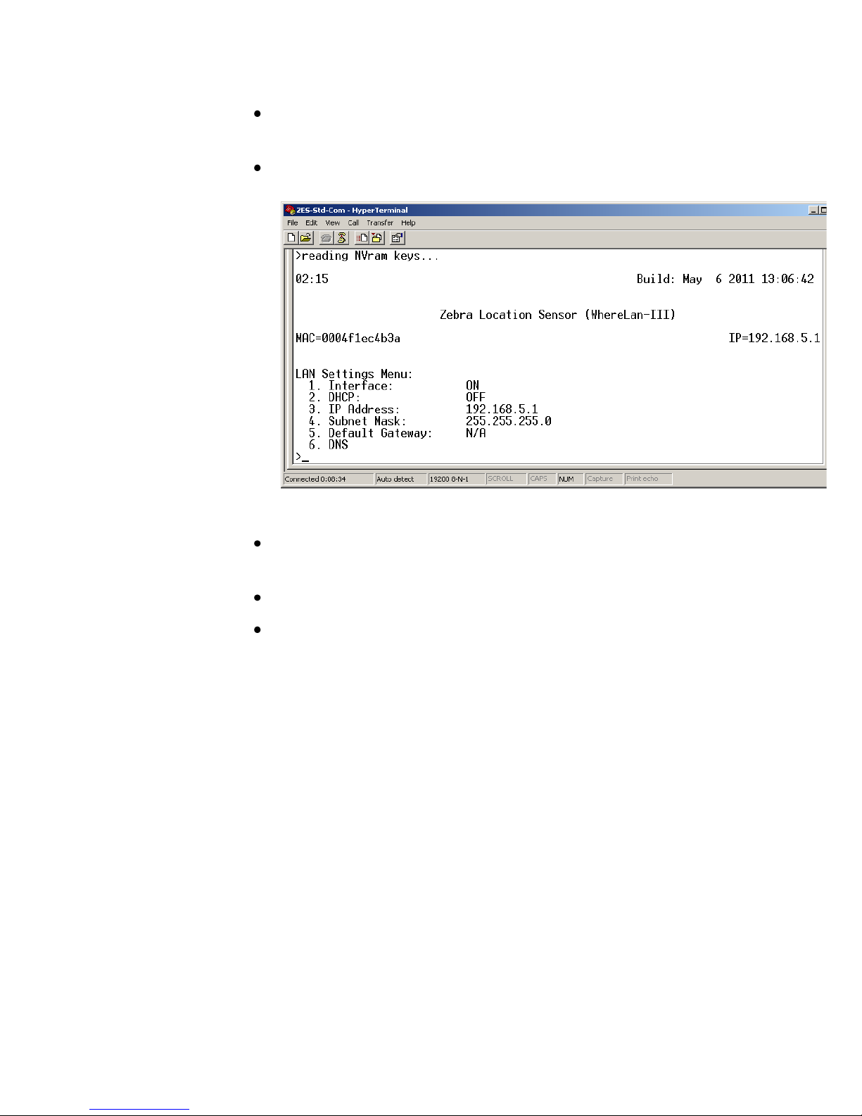
Select 1 for setting Boot Method, Flash for internal image or Network
for image.
Select 2 for wired LAN Port IP setting or 3 WLAN client IP/DHCP
setting.
Save the configuration changes by using ESC key entering the
password “ff2”.
Note changes take effect on unit reboot/reset.
Confirm communication to the Location Sensor by “pinging” the
device from a DOS prompt.
May 2011 D1675 rev B 15
Page 16

WhereLAN III User Guide
5.4 WLAN Client Configuration (LOS-5000-00AB only)
The WLAN embedded in the Location Sensor must be configured with the
proper IP address and Interface must be ON.
Under Ethernet Menu, select 3 WLAN.
Set 1. Interface to ON, then IP/DHCP settings.
Save the configuration changes by using ESC key entering the
password “ff2”.
16 D1675 rev B May 2011
Note changes take effect on unit reboot/reset.
Page 17

WhereLAN III User Guide
Earth Ground Locations.
Bolt Size 8mm. Max
Length 25mm.
6 INSTALLATION AND MOUNTING
Read Installation and Instruction sheet included with the Location Sensor as
well as all Safety and Installation Warnings/Cautions before installing. Follow
the Site Design document for installed location.
6.1 Safety and Installation Warnings and Cautions
Warning - Electrical Shock: A protective earthing conductor with
green and yellow insulation, minimum of 18 AWG, shall be installed to the
protective earthing terminal of the metal enclosure. National electrical codes
shall be followed to install facility protective earthing conductor to the
protective earthing terminal.
Figure 2 Safety and
Warnings
Warning - Electrical Shock: No operator serviceable parts inside. Refer
servicing to qualified personnel. To prevent electrical shock, do not remove
covers.
Caution - The Location Sensor hardware must be installed by a qualified
service technician.
Caution - Use of Zebra external power supply is limited to indoor use
and a max 40° C environment.
May 2011 D1675 rev B 17
Page 18

WhereLAN III User Guide
____________
Note
____________
Safety Lanyard Points
Nut Pocket
Mounting Bracket Points
6.2 Mounting
The site design specifies the location of the Location Sensor(s) to provide
optimum system performance. It is critical that the Location Sensor is
mounted in a position which provides good RF visibility to the tracked assets.
Thus the Location Sensor must be mounted exactly in the position specified in
the site design document.
The Location Sensor has two methods of mounting.
The first can be hung using nut pocket on top for attachment to accept
a 3/8 in (10 mm) threaded rod and jam nut, useful when using a beam
clamp type of hanger.
The second method of mounting is a pole mount hardware kit. This kit
is available separately, ZES Part Number RM-510-00 Mounting
Bracket, Pole Mount.
Figure 3 Mounting Points
Failure to mount the Location Sensor in the exact position specified in the
site design will result in erroneous or non-locates of the tracked assets.
18 D1675 rev B May 2011
Page 19

____________
____________
WhereLAN III User Guide
For safety, it is strongly recommended that a Safety Lanyard be employed
with either mounting method. The Safety Lanyard points are large enough
to accept a 1/8” loop style wire rope. Stainless Steel Rope is recommended.
Figure 4 Safety Lanyard
May 2011 D1675 rev B 19
Page 20

WhereLAN III User Guide
6.3 3/8ths Threaded Rod
The Location Sensor can be hung via a 3/8 inch (10 mm) threaded rod per the
following instructions. The required supports, threaded rod, nuts, etc., are not
included.
Cut the threaded rod to the desired length and install it directly above
the desired Location Sensor position.
Thread one nut up 2 in (50 mm) from the bottom of the threaded rod,
with Lock Washer and Washer.
Place the second nut onto threaded rod, flush with the end of the
threaded rod and install the Location Sensor.
Tighten the upper nut down on top of the Location Sensor housing.
Figure 5 Threaded-Rod
20 D1675 rev B May 2011
Page 21

WhereLAN III User Guide
6.3.1 Safety Lanyard with Threaded Rod
For Location Sensor installation using the Threaded Rod Mounting, it must
also be secured to the building infrastructure with a safety lanyard through the
one of the rectangular loops on top of the casting. See below in Figure 6
Safety Lanyard.
Figure 6 Safety Lanyard
May 2011 D1675 rev B 21
Page 22

WhereLAN III User Guide
Top of Bracket
6.4 Pole Mount Kit
The pole mount kit, catalog number RM-510-00, must be ordered separately.
The pole mount kit will allow the Location Sensor to be mounted to either a
pole or 1-1/4” metal channel framing, per the instructions included with the
pole mount kit.
Figure 7 Pole Mount Kit
22 D1675 rev B May 2011
Page 23

WhereLAN III User Guide
6.4.1 Pole Mount on Metal Frame
1. Mount bracket to metal frame in location, orientation and height specified
in the site design, with support hooks up and retaining slots down, using
supplied clamp.
Figure 8 Bracket Mount
May 2011 D1675 rev B 23
Page 24

WhereLAN III User Guide
Retaining Bolts
2. Loosen the retaining bolts on each side of the Location Sensor but do not
remove them.
Figure 9 Retaining Bolts
3. Hang the Location Sensor on the bracket and tighten retaining bolts
securely.
24 D1675 rev B May 2011
Page 25

WhereLAN III User Guide
4. Install safety lanyard through one of the Location Sensor’s lanyard points,
and the other end of the lanyard to a point above the Location Sensor.
Figure 10 Location Sensor Mounted
May 2011 D1675 rev B 25
Page 26

WhereLAN III User Guide
6.4.2 Pole Mount on Pole
1. First mount bracket to pole at height location, orientation and height
specified in the site design, with support hooks up and retaining slots
down, using supplied clamp.
Figure 11 Pole Mount on Pole
2. Loosen the retaining bolts on each side of the Location Sensor, but do not
remove them. (See Figure 9 Retaining Bolts).
3. Hang the Location Sensor on the bracket and tighten retaining blots
securely.
4. Install safety lanyard through one of the Location Sensor’s lanyard points,
and the other end of the lanyard to a point above the Location Sensor.
26 D1675 rev B May 2011
Page 27

WhereLAN III User Guide
Figure 12 Location Sensor on Pole
May 2011 D1675 rev B 27
Page 28

WhereLAN III User Guide
7.1.1 All Weather Omni
7 ANTENNAS
Two different antennas are available for the Location Sensor. The standard
antenna is the All Weather Omni AK-210-10, which can be bolted directly to
the Location Sensor housing. The Office Omni AK-110-10 is available for
indoor only installations where appearance is critical. The choice of antenna
will be specified in the site design.
Figure 13 Office Omni
Figure 14 All Weather Omni
As its name suggests, the All Weather Omni provides omni-directional
coverage and is suitable for outdoor environments. It should be attached
directly to the Location Sensor housing, and therefore requires no additional
mounting. For this reason, it is the preferred antenna for the Location Sensor.
Because it is an omni-directional antenna, the coverage pattern of the All
Weather Omni can be degraded if mounted too close to metallic structures.
Therefore, the All Weather Omni must be mounted a minimum of 12 inches
(305 mm) from nearby metallic structures.
28 D1675 rev B May 2011
Page 29

WhereLAN III User Guide
Min 12 inches
(305 mm) from
metal wall
I Beam
Right
antenna
Left
antenna
Min 12 inches
(305 mm) from
metal wall
Location
Sensor
Wall
Mount
Bracket
Right
Antenna
Left
Antenna
_____________
_____________
Figure 15 Minimum Clearance to Metallic Structures
The All Weather (and Indoor Office) Omni antennas must be mounted a
minimum of 12 inches (305 mm) away from metal walls.
For best diversity reception, the Location Sensor should be mounted in an
orientation in which the antennas are at a diagonal (45 deg) orientation with
respect to surrounding walls and aisles. The RM-250 Wall Mount Bracket
can be utilized to provide the necessary clearance from nearby metallic
surfaces.
Figure 16 Corner Mount Industrial Application
May 2011 D1675 rev B 29
Page 30

WhereLAN III User Guide
Ceiling tile
Diagonal orientation
of antennas
Minimum 12 in
(305 mm) clearance
to metal walls
17 in
(432 mm)
24 in
(610 mm)
7.1.2 Indoor Omni
The indoor omni is designed to be mounted directly to the ceiling. It has a
small profile designed to be unobtrusive in an office environment. Like the
All Weather Omni antenna, it must be mounted a minimum of 12 inches from
metal walls. There is no spacing requirement for drywall or other nonmetallic walls. For best diversity reception, mount the antennas in a diagonal
orientation 24 in (610 mm) from each other, in the center of the corridor (if
applicable), as shown in Figure 17 below. Be certain to note which antenna is
on the left, and which is on the right, and connect them to the appropriate
ports on the Location Sensor during installation.
30 D1675 rev B May 2011
Figure 17 Office Omnidirectional in Corridor
Page 31

WhereLAN III User Guide
____________
____________
7.2 Vertical Diversity Mounting
For outdoor installation requiring the maximum location accuracy and
consistency, the use of vertical diversity for antenna placement should be
implemented. Installations such as Yard Sites and Marine Terminal Sites will
require that vertical diversity be installed. Zebra Location Solutions offers
three different vertical diversity cable kits for installation.
it is recommended that the Right antenna be higher than the Left Antenna.
Consult instruction sheet included in each kit and WhereLAN III Installation
Guide D1677 for further installation information.
1) Antenna Extension Cable Kit,
CBL-010-10
, which is a 5ft. cable kit is
typically used for Yard Sites.
2) Antenna Extension Cable Kit, CBL-015-10 a 15ft. standard cable kit is
used for Marine Terminals.
3) Cable Kit CBL-015-11, Low Loss Antenna Extension, Location Sensor,
15ft. may be used for Marine Terminals.
The most critical item in placing and installing the Location Sensors is to
ensure that the antennas are not blocked by nearby structures. Detailed
instructions with several examples are provided in the Location Sensor
Placement Guide D0406.
For accurate locate performance, the position of the left and right antennas
must be individually specified in the site design. System Builder requires the
center point and orientation of the antennas.
The left and right antenna must be correctly oriented per the site design.
Inadvertently reversing the left and right antenna will result in a two foot
location error.
For all installations,
May 2011 D1675 rev B 31
Page 32

WhereLAN III User Guide
7.2.1 Example Configuration Using CBL-010-10:
The following diagram is an example of how to achieve vertical diversity,
using ¾” PVC schedule 40 conduit and ¾” PVC conduit fitting.
Carefully coil excess cable for Right Channel.
Figure 18 Vertical Diversity 5ft.
*Use Splicing tape and ZES GS-888-00 connect sealant, install weather tight
cover. For Both Right and Left Antenna Connections.
32 D1675 rev B May 2011
Page 33

WhereLAN III User Guide
7.2.2 Example Configuration Using CBL-015-10:
Below is a picture of a ZES Location Sensor installed on a 100’ light pole.
Note the Vertical Diversity (“VD”) created by extended antennas above and
below the Location Sensor. The installer will have to achieve at a minimum
the vertical distance of 11’ see below, the VD can be greater than 11’. This
installation calls for 12’ of diversity.
The picture shows ¾” electrical metallic tubing extending the “bullhorn”
antennas (white).
Figure 19 Vertical Diversity +11ft.
May 2011 D1675 rev B 33
Page 34

WhereLAN III User Guide
LAN Antenna Indoor 2.2dBi
LAN Antenna Omni 5.2dBi
LAN Antenna Directional
13.5dBi
AK-170-00
AK-151-00
AK-153-00
7.2.3 Vertical Diversity Connections
Make appropriate connection to the Location Sensor, as shown below.
Figure 20 Vertical Diversity Connections
7.3 Antenna WLAN 802.11
For the LOS-5000-01AB, there are three antenna options, and require the
WLAN cable and mounting bracket kit. (Contact ZES Project Manager or
Sales Rep. for appropriate part number). See instruction sheet included with
cable mounting bracket kit regarding installation. See Site Design for specifics
of WLAN antenna choice and orientation.
34 D1675 rev B May 2011
Page 35

WhereLAN III User Guide
8 CABLING
Figure 21 (below) labels the appropriate connections which must be made to
the Location Sensor in normal operation. The connector types and
recommended cable types are detailed in Section 3.
Figure 21 Location Sensor Connections
For all outdoor installations:
Use part GS-888-00 grease (supplied with unit) in ALL Connecter
Jacks. Fill each of the following connections with Nyogel Weather
Sealant; these include the Left and Right antenna, Timing connections,
Wifi Client, Ethernet, Serial interface, and Power connection. This is
to help weatherproof the connections from water and corrosion.
Routing the cables through the Drip Plug, supplied with unit, plug
cables into units and fully (carefully) install Drip Plug into connector
well.
Figure 22 Drip Plug
May 2011 D1675 rev B 35
Page 36

WhereLAN III User Guide
_____________
_____________
_____________
_____________
8.1 Power, AC
WhereLAN III location sensor, can either be powered via POE (Power Over
Ethernet, 802.3af compliant) or directly with a standalone DC power supply.
If the standalone DC power supply option is used, the customer must provide
100-240Vac power 50/60 Hz to the specified Location Sensor position. The
Location Sensor units require DC 36-57V, 250mA for operation (12 Watts).
The recommended power supply (PS-040-00), which must be purchased
separately, has a 6 ft. (2 m) AC cable and a 6 ft. (2 m) DC cable. The
electrician should verify that the AC power is available within 6 ft. (2 m) of
the position of the Location Sensor. This allows a 6 ft. (2 m) “service loop”
margin if the Location Sensor position must be readjusted after the AC power
is installed.
The Location Sensor must always be used with the specified power
supply. The use of a different power supply could result in equipment
damage and/or electric shock or fire hazard.
Two optional 50 ft. (15 m) DC power extension cables are available for
installations where it is not desirable to route the AC power within 6 ft. (2 m)
of the Location Sensor. One is for indoor use only and is Plenum Rated, ZES
Part Number PX-010-00. The other is an outdoor rated (UV stable), ZES
Part Number PX-050-00. Consult your ZES Account Manager for
recommended wire size if additional lengths are required for a particular
installation.
Power Supplies have a limited safe operating temperature rating, please
check with the account representative concerning limitations or
availability of extended temperature range power supply, such as PS-040-
00. In outdoor installations, the power supply must be installed within a
suitable waterproof housing per applicable building codes. The use of a
non-qualified housing could result in equipment damage and/or electric
shock or fire hazard.
36 D1675 rev B May 2011
Page 37

WhereLAN III User Guide
____________
Note
____________
____________
Note
____________
____________
____________
8.1 Ethernet
The Location Sensor utilizes standard 10/100 802.3 Ethernet connectivity via
Cat-5 cables. The Location Sensor must be wired to a nearby hub, which is in
turn connected to the network containing the database CPU. The maximum
Ethernet cable run is 328 ft. (100 m). If additional distance is required, hubs,
repeaters, and fiber (with 10BaseT converters) can be used to extend the
distance. Refer to IEEE guidelines for Ethernet cabling.
Do not exceed the maximum Ethernet cabling length of 328 ft. (100 m).
8.2 Timing Cable Interconnection Guidelines
For some applications, the Location Sensor requires a timing cable to be
connected to other nearby Location Sensor units. The site design document,
provided by the site designer, will specify which Location Sensors will be
connected together. Each of the three timing ports on the Location Sensor is
an identical bi-directional link. The cable and connector types are specified in
section 0 above.
The following rules must be applied when connecting timing cables between
the Location Sensors:
Do not connect the timing cable from one Location Sensor back to the
same Location Sensor.
Do not connect two timing cables between the same two Location
Sensors.
The maximum timing cable length is 1000 ft. (305 m).
Do not exceed the maximum timing cabling length of 1000 ft. (305 m).
Install the Location Sensor timing cables from one unit to the next, as
specified in the site design document, using the specified 2-pair or 4-pair*
cable and RJ22 (telephone handset 4c4p) connectors. (* see 8.2.1.) Incorrect
routing of the timing cables between the Location Sensors may result in
decreased location accuracy.
May 2011 D1675 rev B 37
Page 38

WhereLAN III User Guide
8.2.1 Timing Cable Pin-Out
RJ22
2 Pair Cat-
To pin 1 white/orange
To Pin 2 orange
To pin 3 white/blue
To pin 4 blue
____________
Note
____________
This Cat-5 two-pair cable should be constructed with straight through wiring,
with pin 1 on one end routed to pin 1 on the other end. For the 2 pair Cat-5
cable, the following pin out must be used. (see Figure 23).
Pair 1: Orange/white wire is pin 1; orange wire is pin 2.
Pair 2: White/blue wire is pin 3; blue wire is pin 4.
Figure 23 Timing Cable Wiring Pin Out
For a reliable system operation, the jacket of the timing cable must be
securely crimped inside the RJ-22 (4p4c) connector. It is recommended
that a 2-pair cable be utilized to ensure a proper crimp. Standard eight
conductor Cat-5 cable may be used, and follow the steps in Section 8.2.2
of this guide.
38 D1675 rev B May 2011
Page 39

WhereLAN III User Guide
8.2.2 Cat-5 Four-Pair Installation
Steps:
1. Trim out Jack back approximately ½ inch.
Figure 24 Timing Cable Trim
2. Pull Back Jack until at least 1-1/4” inches of wire is exposed. Separate
Blue/White and Orange/White pair from Green/White and Brown/White
pair.
Figure 25 Timing Cable Jacket
May 2011 D1675 rev B 39
Page 40

WhereLAN III User Guide
3. Trim the Green/White and Brown/White Pairs flush with outer jacket.
Figure 26 Timing Cable Trim
4. Pull outer jacket back up leaving only ¼ inch of wire exposed. Separate
wires as shown in Figure 27 and trim wires evenly.
Figure 27 Timing Cable Pull Jacket
40 D1675 rev B May 2011
Page 41

WhereLAN III User Guide
8.2.3 Timing Cable Test Procedure
5. Insert into RJ-22(4p4c) as shown and crimp with appropriate tool. Note
outer cable jacket is captured by strain relief.
The timing cables must be properly wired in order for the timing signal to be
transmitted from one Location Sensor to the other. It is recommended that
this test be completed on each cable by the installer prior to operation. This
test requires two 4-pair to 2-pair connector adapters (ZES p/n 21204), and a
Fluke 620 CableMeter. Brief instructions are provided below; consult the
Fluke CableMeter instruction manual for detailed instructions.
Figure 28 Timing Cable Crimp
May 2011 D1675 rev B 41
Page 42

WhereLAN III User Guide
2 pair adapters
Cable
under test
Setup
Connect adapter #1 between the Fluke 620 CableMeter and the near end of the
cable to be tested. Connect the Fluke Cable ID unit and adapter #2 to the far
end of the cable to be tested using an RJ-45 coupler.
Figure 29 Test setup for CAT5 cable using Fluke 620
Procedure
1. Use the SETUP to select cable type, wire standard, category and wire size
on the Fluke CableMeter:
Cable: UTR
Wiring: 10BaseT 2PR
Category: Cat5
Wire Size: AWG24
2. Turn the Fluke CableMeter rotary switch to WIRE MAP. The correct
readout when testing 2-pair cable is shown in Figure 30 below. If a
different readout appears, the cable was not constructed properly and must
be corrected.
42 D1675 rev B May 2011
Page 43

WhereLAN III User Guide
Location Sensor
Outdoor
Omni
Antenna
Power/
Health
Tag
Reception
Ethernet
WLAN
12 36 ID
12 36 #1
Figure 30 Correct Readout when Testing 2-pair cable.
8.3 Location Sensor Operational Verification
Prior to optimizing locate performance, the operation of the Location Sensor
must be verified. The checklist below specifies the verification of the
configuration and basic operation.
Figure 31 Location Sensor LED Indicators
May 2011 D1675 rev B 43
Verify that each Location Sensor is operational by verifying that the
left Power/ Health LED is illuminated solid red.
Page 44

WhereLAN III User Guide
Initial
Date
Comments/ Exceptions
For wired 802.3 Location Sensors, verify that the Ethernet LED is
solid red when connected and blinking red when activity is present.
Verify that the RX detects LED is blinking red indicating reception of
tag blinks.
For wireless 802.11b Location Sensors, verify that the WLAN activity
LED is blinking red during power up state and solid red otherwise.
Confirm that the site Location Sensor channel assignment is correct by
running “display locate” from the LP Manager tool with a tag placed
directly under each LS. Verify that the nearest Location Sensor, as
indicated by a “0” in the display locate report, is that Location Sensor
nearest the tag.
Verify that detects are received on the channel by using either LP
Manager Detect History, or WTLPHealth. LS detects when a tag is
placed at a distance from each Location Antenna equivalent to the
maximum required range from that Location Antenna. Typical tag to
Location Antenna range is 1000 ft (305 m) (Unobstructed/outdoor),
350 ft. (107 m) Minimally Obstructed (indoor office/ light
commercial), 250 feet (76 m) Significantly Obstructed (heavy
industrial).
Section Signoff
44 D1675 rev B May 2011
Page 45

WhereLAN III User Guide
AT
BE
BG
CY
CZ
DK
EE
FI
FR
DE
GR
HU
IE
IT
LV
LT
LU
MT
NL
PL
PT
RO
SK
SI
ES
SE
GB IS
LI
NO
CH TR
9 REGULATORY INFORMATION
FCC & IC Requirements
This device complies with Part 15 of the FCC Rules. Operation is subject to the
following two conditions: (1) this device may not cause harmful interference,
and (2) this device must accept any interference received, including interference
that may cause undesired operation.
This equipment has been tested and found to comply with the limits for Class A
devices, pursuant to Part 15 of the FCC Rules.
This ISM device complies with Canadian ICES-001.
Cet appareil ISM est conforme à la norme NMB-001 du Canada.
9.1 RF Notice
Any changes or modifications to ZES Corp. equipment not expressly approved by
ZES could void the user’s authority to operate the equipment.
FCC Radiation Exposure Statement
This equipment complies with FCC radiation exposure limits set forth for an
uncontrolled environment. This equipment should be installed and operated with
minimum distance 20 cm between the radiator and your body. This transmitter must
not be co-located or operating in conjunction with any other antenna or transmitter.
9.2 EU Compliance Information (LOS-5000-00AA & LOS-
5000-00AB)
Approved for use in the following countries.
Note: Use is restricted for countries that are grayed out. See below for
limitations.
May 2011 D1675 rev B 45
Page 46

WhereLAN III User Guide
Important Notice:
This RF device is intended for indoor and outdoor
use in all EU and EFTA with the following
limitations.
France: Outdoor use limited to 10 mW e.i.r.p.
within the band 2454-2483.5 MHz
Italy: For private use, a general authorization is
required if WAS/RLAN’s are used outside own
premises. For public use, a general authorization is
required.
Luxembourg: General authorization required for
network and service supply.
Norway: Wideband Data Transmission systems
2400.0-2483.5 MHz does not apply for the
geographical area within a radius of 20 km from
the centre of Ny-Ålesund
46 D1675 rev B May 2011
Page 47

WhereLAN III User Guide
APPENDIX A: LOS-5000 EFFECTIVE PROJECTED
AREA (EPA)
LOS Housing
Housing Size (Inches) [cm]: 12.0” [30.4] Wide, 10.3” High [26.2], 1.7” [4.3] Deep
Housing Size with 1/2" Radial Ice (Inches) [cm]: 12.5” [31.8] Wide, 10.8” High [27.4], 2.3” [5.8]
Deep
Maximum Projected Area with Ice (Square Inches): 135.0” [2212 cc]
Shape Factor (CD per EIA-222-F) 1.4
Effective Projected Area with Ice (Square Inches) 189 [3097cc]
Omni Antenna (One Antenna)
Antenna Size (Inches) [cm]: 1.3 [3.3] Diameter 19.0 [302] Long
Antenna Size with 1/2" Radial Ice (Inches): 2.3 [5.8] Diameter 20.0 [50.8] Long
Maximum Projected Area with Ice (Square Inches): 46.6 [763cc]
Shape Factor (CD per EIA-222-F) 0.8
Effective Projected Area with Ice (Square Inches) 37.3 [611cc]
LOS-5000 Effective Projected Area (EPA)
LOS Housing with Ice (Inches): 189 [3097cc]
Omni Antenna #1 with Ice (Inches): 37.3 [611cc]
Omni Antenna #2 with Ice (Inches): 37.3 [611cc]
Total Effective Projected Area with 0.5 inch Radial Ice
Effective Projected Area, Total (Square Inches): 263.6 [4319cc]
Note: The above does not include conduit/cabling for Omni Antenna polarization diversity and
LOS-5000 power.
May 2011 D1675 rev B 47
Page 48

WhereLAN III User Guide
APPENDIX B: LOS-5000 WEIGHT
LOS-5000 Housing
Housing Weight (Pounds): 7.0 [3.17.0Kg]
Ice Volume at 0.5 inch [12.7mm] Radial Thickness: 94.7 Cubic Inches [1552cc]
Assumed density of Ice: 0.032 pounds per cubic inch [0.90 g/cc]
Mass of Ice: 3.0 pounds [1.4Kg]
Housing and Ice Mass: 10.0 pounds [4.53Kg]
Omni Antenna (One Antenna)
Antenna Weight: 0.8 pounds [0.36Kg]
Ice Volume at 0.5 inch [12.7mm] Radial Thickness: 58.9 Cubic inches [965 cc]
Assumed density of Ice: 0.032 pounds per cubic inch [0.90 g/cc]
Ice Weight: 1.9 pounds [.86Kg]
Antenna and Ice Weight: 2.7 pounds [1.22Kg)
Total Weight with 1/2" Radial Ice
LOS Housing Ice: 10.0 pounds [4.53Kg]
Omni Antenna #1 with Ice: 2.7 pounds [1.22Kg]
Omni Antenna #1 with Ice: 2.7 pounds [1.22Kg]
Weight, Total: 15.4 pounds [6.98Kg]
Note: The above does not include conduit/cabling for Omni Antenna polarization diversity and
LOS-5000 power.
48 D1675 rev B May 2011
 Loading...