

LI4278
PRODUCT
REFERENCE GUIDE


LI4278
PRODUCT REFERENCE GUIDE
72E-151834-10
Revision A
December 2020

ii LI4278 PRODUCT REFERENCE GUIDE
No part of this publication may be reproduced or used in any form, or by any electrical or mechanical means,
without permission in writing from Zebra. This includes electronic or mechanical means, such as photocopying,
recording, or information storage and retrieval systems. The material in this manual is subject to change
without notice.
The software is provided strictly on an “as is” basis. All software, including firmware, furnished to the user is on
a licensed basis. Zebra grants to the user a non-transferable and non-exclusive license to use each software
or firmware program delivered hereunder (licensed program). Except as noted below, such license may not be
assigned, sub-licensed, or otherwise transferred by the user without prior written consent of Zebra. No right to
copy a licensed program in whole or in part is granted, except as permitted under copyright law. The user shall
not modify, merge, or incorporate any form or portion of a licensed program with other program material, create
a derivative work from a licensed program, or use a licensed program in a network without written permission
from Zebra. The user agrees to maintain Zebra’s copyright notice on the licensed programs delivered
hereunder, and to include the same on any authorized copies it makes, in whole or in part. The user agrees not
to decompile, disassemble, decode, or reverse engineer any licensed program delivered to the user or any
portion thereof.
Zebra reserves the right to make changes to any software or product to improve reliability, function, or design.
Zebra does not assume any product liability arising out of, or in connection with, the application or use of any
product, circuit, or application described herein.
No license is granted, either expressly or by implication, estoppel, or otherwise under any Zebra Technologies
Corporation, intellectual property rights. An implied license only exists for equipment, circuits, and subsystems
contained in Zebra products.
Warranty
For the complete Zebra hardware product warranty statement, go to:
www.zebra.com/warranty.

Revision History
Changes to the original guide are listed below:
Change Date Description
-01 Rev. A 1/2012 Initial Release
-02 Rev. A 4/2013 Added:
- HID features for Apple iOS
- Unsolicited Heartbeat Interval
- Dump Scanner Parameters
- Changed Parameter #s to Attribute #s
- Added attribute #s.
-03 Rev. A 7/2013 Updated:
- Cosmetic updates throughout the guide
- Page 8-5, Note #2.
- Matrix 2 of 5 Lengths default verbiage
- ISBT Concatenation: changed bar code value of Autodiscriminate to 02h
-04 Rev. A 10/2014 Zebra Rebranding
iii
-05 Rev. A 1/2015 Updated formula for the number of storable bar codes with correct memory size
(9,000 instead of 30,720 bytes of memory).
-05 Rev. B 3/2015 Zebra Rebranding
-06 Rev. A 7/2015 Updated Zebra logo & copyright; deleted Glossary; added Communication Protocol
Tab le
-07 Rev. A 7/2016 Updated Advanced Data Formatting chapter.
-08 Rev. A 5/2019 Updated:
- Note for USB Device Type on pg. 8-5
- USB OPOS Hand-held to OPOS (IBM Hand-held with Full Disable) on
pgs. 8-5, G-1 and G-3
- HID Keyboard Emulation to USB HID Keyboard on pgs.4-12, 4-35, 8-4, 8-5,
8-7, 8-9, 8-10, 8-12, A-4, G-1, and G-3
- MOD 10/MOD 11 to MOD 11/MOD 10 on pg. 11-54
- Zebra copyright statement on the last page.
-09 Rev. A 3/2020 Updates:
- Scanner to cradle range update.
- 123Scan
- Copyright.
- URLs.
-10 Rev. A 12/2020 Replaced all references of master/slave with central/peripheral.
2
to 123Scan.

iv LI4278 PRODUCT REFERENCE GUIDE

TABLE OF CONTENTS
Warranty ......................................................................................................................................... ii
Revision History.............................................................................................................................. iii
About This Guide
Introduction ..................................................................................................................................... xv
Scanner Configurations .................................................................................................................. xv
Related Product Line Configurations .............................................................................................. xvii
Chapter Descriptions ...................................................................................................................... xxi
Notational Conventions................................................................................................................... xxii
Related Documents ........................................................................................................................ xxiii
Service Information......................................................................................................................... xxiii
Chapter 1: GETTING STARTED
Introduction .................................................................................................................................... 1-1
Interfaces ....................................................................................................................................... 1-2
Unpacking the Linear Imager Scanner and Cradle ........................................................................ 1-2
Parts ............................................................................................................................................... 1-3
Scanner .................................................................................................................................... 1-3
CR0078-S/CR0008-S Series Cradle ........................................................................................ 1-4
CR0078-P Series Cradle ............................................................................................................... 1-6
Linear Imager Scanner Cradle ....................................................................................................... 1-7
Connecting the CR0078-S/CR0008-S Series Cradle ............................................................. 1-8
Supplying Power to the CR0078-S/CR0008-S Cradle ............................................................. 1-8
Connecting the CR0078-P Series Cradle ............................................................................... 1-9
Supplying Power to the CR0078-P Cradle ............................................................................... 1-9
Lost Connection to Host ........................................................................................................... 1-10
Mounting the Cradle ................................................................................................................. 1-10
Replacing the Linear Imager Scanner Battery ............................................................................... 1-11
Charging the Linear Imager Scanner Battery ................................................................................ 1-12
Turning Off the Linear Imager Scanner Battery ............................................................................. 1-12
Reconditioning the Linear Imager Scanner Battery ....................................................................... 1-13
Battery Reconditioning LED Definitions ................................................................................... 1-13

vi LI4278 PRODUCT REFERENCE GUIDE
Inserting the Linear Imager Scanner in the Cradle ........................................................................ 1-14
Inserting Linear Imager Scanner in the CR0078-S/CR0008-S Cradle ..................................... 1-14
Horizontal Cradle Mount .................................................................................................... 1-14
Vertical Cradle Mount ........................................................................................................ 1-14
Inserting/Removing Linear Imager Scanner in the CR0078-P Cradle ..................................... 1-15
Wall Mount Bracket Template ........................................................................................................ 1-17
Radio Communications .................................................................................................................. 1-18
Configuring the Linear Imager Scanner ......................................................................................... 1-18
Accessories ................................................................................................................................... 1-18
Lanyard .................................................................................................................................... 1-18
Chapter 2: SCANNING
Introduction .................................................................................................................................... 2-1
Beeper and LED Definitions .......................................................................................................... 2-1
Cradle LED Definitions ............................................................................................................. 2-5
Scanning ....................................................................................................................................... 2-6
Aiming ...................................................................................................................................... 2-6
Hand-Held Scanning ................................................................................................................ 2-6
Hands-Free Scanning .............................................................................................................. 2-7
Decode Ranges ............................................................................................................................. 2-8
Chapter 3: MAINTENANCE, TROUBLESHOOTING & TECHNICAL SPECIFICATIONS
Introduction .................................................................................................................................... 3-1
Maintenance .................................................................................................................................. 3-1
Known Harmful Ingredients ...................................................................................................... 3-1
Approved Cleaning Agents ...................................................................................................... 3-2
Cleaning the Linear Imager Scanner ....................................................................................... 3-2
Cleaning the Linear Imager Scanner Cradles .......................................................................... 3-2
Battery Information ........................................................................................................................ 3-3
Troubleshooting ............................................................................................................................. 3-4
Technical Specifications ................................................................................................................ 3-9
Cradle Signal Descriptions ............................................................................................................ 3-13
Chapter 4: RADIO COMMUNICATIONS
Introduction .................................................................................................................................... 4-1
Scanning Sequence Examples ................................................................................................ 4-1
Errors While Scanning ............................................................................................................. 4-1
Radio Communications Parameter Defaults .................................................................................. 4-2
Wireless Beeper Definitions ........................................................................................................... 4-3
Radio Communications Host Types .............................................................................................. 4-3
Bluetooth Technology Profile Support ........................................................................................... 4-6
Central/Peripheral Set Up ........................................................................................................ 4-6
Central ............................................................................................................................... 4-6
Peripheral ........................................................................................................................... 4-6
Bluetooth Friendly Name ......................................................................................................... 4-7
Discoverable Mode .................................................................................................................. 4-7
HID Host Parameters ..................................................................................................................... 4-8
HID Features for Apple iOS ..................................................................................................... 4-8

Table of Contents vii
HID Country Keyboard Types (Country Codes) ....................................................................... 4-9
HID Keyboard Keystroke Delay ............................................................................................... 4-11
HID CAPS Lock Override ......................................................................................................... 4-11
HID Ignore Unknown Characters ............................................................................................. 4-12
Emulate Keypad ....................................................................................................................... 4-12
HID Keyboard FN1 Substitution ............................................................................................... 4-13
HID Function Key Mapping ...................................................................................................... 4-13
Simulated Caps Lock ............................................................................................................... 4-14
Convert Case ........................................................................................................................... 4-14
Auto-reconnect Feature ................................................................................................................. 4-15
Reconnect Attempt Beep Feedback ........................................................................................ 4-16
Reconnect Attempt Interval ...................................................................................................... 4-17
Auto-reconnect in Bluetooth Keyboard Emulation (HID Peripheral) Mode .............................. 4-19
Out of Range Indicator ................................................................................................................... 4-20
Beep on Insertion ........................................................................................................................... 4-20
Linear Imager Scanner(s) To Cradle Support ................................................................................ 4-21
Modes of Operation ................................................................................................................. 4-21
Point-to-Point Communication ........................................................................................... 4-21
Multipoint-to-Point Communication .................................................................................... 4-21
Parameter Broadcast (Cradle Host Only) ................................................................................ 4-22
Pairing ...................................................................................................................................... 4-22
Pairing Modes .................................................................................................................... 4-23
Lock Override ..................................................................................................................... 4-23
Pairing Methods ................................................................................................................. 4-24
Unpairing ............................................................................................................................ 4-24
Pairing Bar Code Format ......................................................................................................... 4-25
Pairing Bar Code Example ................................................................................................. 4-25
Connection Maintenance Interval ............................................................................................ 4-25
Considerations ................................................................................................................... 4-25
Batch Mode .................................................................................................................................... 4-28
Modes of Operation ............................................................................................................ 4-28
Page Button ................................................................................................................................... 4-30
Bluetooth Security .......................................................................................................................... 4-31
Authentication .......................................................................................................................... 4-31
PIN Code ................................................................................................................................. 4-32
Variable PIN Code ............................................................................................................. 4-32
Encryption ................................................................................................................................ 4-33
Secure Simple Pairing IO Capability (SPP Server and SPP Central Host Mode Only) ........... 4-34
Bluetooth Radio, Linking, and Batch Operation ............................................................................. 4-35
Setting Up an iOS or Android Product To Work With The Linear Imager Scanner .................. 4-35
Chapter 5: USER PREFERENCES & MISCELLANEOUS SCANNER OPTIONS
Introduction .................................................................................................................................... 5-1
Scanning Sequence Examples ...................................................................................................... 5-2
Errors While Scanning ................................................................................................................... 5-2
User Preferences/Miscellaneous Option Parameter Defaults ........................................................ 5-2
User Preferences ........................................................................................................................... 5-4
Default Parameters .................................................................................................................. 5-4
Report Version ......................................................................................................................... 5-5
Parameter Bar Code Scanning ................................................................................................ 5-5

viii LI4278 PRODUCT REFERENCE GUIDE
Beep After Good Decode ......................................................................................................... 5-6
Decode Illumination Indicator ................................................................................................... 5-6
Beeper Tone ............................................................................................................................ 5-7
Suppress Power Up Beeps ...................................................................................................... 5-8
Beeper Volume ........................................................................................................................ 5-8
Beeper Duration ....................................................................................................................... 5-9
Hand-Held Trigger Mode ......................................................................................................... 5-9
Hands-Free Trigger Mode ........................................................................................................ 5-10
Low Power Mode ..................................................................................................................... 5-10
Time Delay to Low Power Mode .............................................................................................. 5-11
Time Delay to Presentation Sleep Mode ................................................................................. 5-12
Timeout to Low Power Mode from Auto Aim ........................................................................... 5-14
Continuous Bar Code Read ..................................................................................................... 5-15
Unique Bar Code Reporting ..................................................................................................... 5-15
Decode Session Timeout ......................................................................................................... 5-16
Timeout Between Decodes, Same Symbol ............................................................................. 5-16
Timeout Between Decodes, Different Symbols ....................................................................... 5-16
Decoding Illumination ............................................................................................................... 5-17
Miscellaneous Scanner Parameters .............................................................................................. 5-18
Transmit Code ID Character .................................................................................................... 5-18
Prefix/Suffix Values .................................................................................................................. 5-19
Scan Data Transmission Format ............................................................................................. 5-20
FN1 Substitution Values .......................................................................................................... 5-21
Transmit “No Read” Message .................................................................................................. 5-22
Unsolicited Heartbeat Interval .................................................................................................. 5-23
Dump Scanner Parameters ..................................................................................................... 5-24
Chapter 6: KEYBOARD WEDGE INTERFACE
Introduction .................................................................................................................................... 6-1
Connecting a Keyboard Wedge Interface ...................................................................................... 6-2
Keyboard Wedge Parameter Defaults ........................................................................................... 6-3
Keyboard Wedge Host Parameters ............................................................................................... 6-4
Keyboard Wedge Host Types .................................................................................................. 6-4
Keyboard Wedge Country Types (Country Codes) ................................................................. 6-5
Ignore Unknown Characters .................................................................................................... 6-7
Keystroke Delay ....................................................................................................................... 6-7
Intra-Keystroke Delay .............................................................................................................. 6-8
Alternate Numeric Keypad Emulation ...................................................................................... 6-8
Caps Lock On .......................................................................................................................... 6-9
Caps Lock Override ................................................................................................................. 6-9
Convert Wedge Data ............................................................................................................... 6-10
Function Key Mapping ............................................................................................................. 6-10
FN1 Substitution ...................................................................................................................... 6-11
Send Make and Break ............................................................................................................. 6-11
Keyboard Map ............................................................................................................................... 6-12
ASCII Character Set for Keyboard Wedge .................................................................................... 6-13
Chapter 7: RS-232 INTERFACE
Introduction .................................................................................................................................... 7-1

Table of Contents ix
Connecting an RS-232 Interface .................................................................................................... 7-2
RS-232 Parameter Defaults ........................................................................................................... 7-3
RS-232 Host Parameters ............................................................................................................... 7-4
RS-232 Host Types .................................................................................................................. 7-6
Baud Rate ................................................................................................................................ 7-8
Parity ........................................................................................................................................ 7-9
Stop Bit Select ......................................................................................................................... 7-9
Data Bits (ASCII Format) ......................................................................................................... 7-10
Check Receive Errors .............................................................................................................. 7-10
Hardware Handshaking ........................................................................................................... 7-11
Software Handshaking ............................................................................................................. 7-13
Host Serial Response Time-out ............................................................................................... 7-15
RTS Line State ......................................................................................................................... 7-16
Beep on <BEL> ........................................................................................................................ 7-16
Intercharacter Delay ................................................................................................................. 7-17
Nixdorf Beep/LED Options ....................................................................................................... 7-18
Ignore Unknown Characters .................................................................................................... 7-18
ASCII Character Set for RS-232 .................................................................................................... 7-19
Chapter 8: USB INTERFACE
Introduction .................................................................................................................................... 8-1
Connecting a USB Interface .......................................................................................................... 8-2
USB Parameter Defaults ................................................................................................................ 8-4
USB Host Parameters .................................................................................................................... 8-5
USB Device Type ..................................................................................................................... 8-5
Symbol Native API (SNAPI) Status Handshaking .................................................................... 8-6
USB Country Keyboard Types (Country Codes) ..................................................................... 8-7
USB Keystroke Delay .............................................................................................................. 8-9
USB CAPS Lock Override ....................................................................................................... 8-9
USB Ignore Unknown Characters ............................................................................................ 8-10
USB Convert Unknown to Code 39 ......................................................................................... 8-10
Emulate Keypad ....................................................................................................................... 8-11
Emulate Keypad with Leading Zero ......................................................................................... 8-11
Quick Keypad Emulation .......................................................................................................... 8-12
USB Keyboard FN 1 Substitution ............................................................................................. 8-12
Function Key Mapping ............................................................................................................. 8-13
Simulated Caps Lock ............................................................................................................... 8-13
Convert Case ........................................................................................................................... 8-14
USB Static CDC ....................................................................................................................... 8-14
Optional USB Parameters .............................................................................................................. 8-15
Ignore Beep ............................................................................................................................. 8-15
Ignore Bar Code Configuration ................................................................................................ 8-15
USB Polling Interval ................................................................................................................. 8-16
ASCII Character Set for USB ......................................................................................................... 8-18
Chapter 9: IBM INTERFACE
Introduction .................................................................................................................................... 9-1
Connecting to an IBM 468X/469X Host ......................................................................................... 9-2
IBM Parameter Defaults ................................................................................................................. 9-3

x LI4278 PRODUCT REFERENCE GUIDE
IBM 468X/469X Host Parameters .................................................................................................. 9-4
Port Address ............................................................................................................................ 9-4
Convert Unknown to Code 39 .................................................................................................. 9-5
Optional IBM Parameters .............................................................................................................. 9-5
Ignore Beep ............................................................................................................................. 9-5
Ignore Bar Code Configuration ................................................................................................ 9-6
Chapter 10: 123SCAN2
Introduction .................................................................................................................................... 10-1
Communication with 123Scan ....................................................................................................... 10-1
123Scan Requirements ................................................................................................................. 10-2
Scanner SDK, Other Software Tools, and Videos ......................................................................... 10-2
Chapter 11: SYMBOLOGIES
Introduction .................................................................................................................................... 11-1
Scanning Sequence Examples ...................................................................................................... 11-1
Errors While Scanning ................................................................................................................... 11-2
Symbology Parameter Defaults ..................................................................................................... 11-2
UPC/EAN ....................................................................................................................................... 11-6
Enable/Disable UPC-A ............................................................................................................. 11-6
Enable/Disable UPC-E ............................................................................................................. 11-6
Enable/Disable UPC-E1 ........................................................................................................... 11-7
Enable/Disable EAN-8/JAN-8 .................................................................................................. 11-7
Enable/Disable EAN-13/JAN-13 .............................................................................................. 11-8
Enable/Disable Bookland EAN ................................................................................................ 11-8
Decode UPC/EAN/JAN Supplementals ................................................................................... 11-9
User-Programmable Supplementals ........................................................................................ 11-12
UPC/EAN/JAN Supplemental Redundancy ............................................................................. 11-12
UPC/EAN/JAN Supplemental AIM ID Format .......................................................................... 11-13
Transmit UPC-A Check Digit ................................................................................................... 11-14
Transmit UPC-E Check Digit ................................................................................................... 11-14
Transmit UPC-E1 Check Digit ................................................................................................. 11-15
UPC-A Preamble ..................................................................................................................... 11-16
UPC-E Preamble ..................................................................................................................... 11-17
UPC-E1 Preamble ................................................................................................................... 11-18
Convert UPC-E to UPC-A ........................................................................................................ 11-19
Convert UPC-E1 to UPC-A ...................................................................................................... 11-19
EAN-8/JAN-8 Extend ............................................................................................................... 11-20
Bookland ISBN Format ............................................................................................................ 11-20
UCC Coupon Extended Code .................................................................................................. 11-21
Coupon Report ......................................................................................................................... 11-21
ISSN EAN ................................................................................................................................ 11-22
Code 128 ....................................................................................................................................... 11-23
Enable/Disable Code 128 ........................................................................................................ 11-23
Set Lengths for Code 128 ........................................................................................................ 11-23
Enable/Disable GS1-128 (formerly UCC/EAN-128) ................................................................. 11-25
Enable/Disable ISBT 128 ......................................................................................................... 11-25
ISBT Concatenation ................................................................................................................. 11-26
Check ISBT Table .................................................................................................................... 11-27

Table of Contents xi
ISBT Concatenation Redundancy ............................................................................................ 11-27
Code 39 ......................................................................................................................................... 11-28
Enable/Disable Code 39 .......................................................................................................... 11-28
Enable/Disable Trioptic Code 39 ............................................................................................. 11-28
Convert Code 39 to Code 32 ................................................................................................... 11-29
Code 32 Prefix ......................................................................................................................... 11-29
Set Lengths for Code 39 .......................................................................................................... 11-30
Code 39 Check Digit Verification ............................................................................................. 11-31
Transmit Code 39 Check Digit ................................................................................................. 11-31
Code 39 Full ASCII Conversion ............................................................................................... 11-32
Code 39 Buffering - Scan & Store ............................................................................................ 11-32
Buffer Data ......................................................................................................................... 11-33
Clear Transmission Buffer .................................................................................................. 11-33
Transmit Buffer ................................................................................................................... 11-34
Overfilling Transmission Buffer .......................................................................................... 11-34
Attempt to Transmit an Empty Buffer ................................................................................. 11-34
Code 93 ......................................................................................................................................... 11-35
Enable/Disable Code 93 .......................................................................................................... 11-35
Set Lengths for Code 93 .......................................................................................................... 11-35
Code 11 ......................................................................................................................................... 11-37
Code 11 ................................................................................................................................... 11-37
Set Lengths for Code 11 .......................................................................................................... 11-37
Code 11 Check Digit Verification ............................................................................................. 11-39
Transmit Code 11 Check Digits ............................................................................................... 11-40
Interleaved 2 of 5 (ITF) .................................................................................................................. 11-41
Enable/Disable Interleaved 2 of 5 ............................................................................................ 11-41
Set Lengths for Interleaved 2 of 5 ............................................................................................ 11-41
I 2 of 5 Check Digit Verification ................................................................................................ 11-43
Transmit I 2 of 5 Check Digit .................................................................................................... 11-43
Convert I 2 of 5 to EAN-13 ....................................................................................................... 11-44
Discrete 2 of 5 (DTF) ..................................................................................................................... 11-45
Enable/Disable Discrete 2 of 5 ................................................................................................. 11-45
Set Lengths for Discrete 2 of 5 ................................................................................................ 11-45
Codabar (NW - 7) ........................................................................................................................... 11-47
Enable/Disable Codabar .......................................................................................................... 11-47
Set Lengths for Codabar .......................................................................................................... 11-47
CLSI Editing ............................................................................................................................. 11-49
NOTIS Editing .......................................................................................................................... 11-49
Codabar Upper or Lower Case Start/Stop Characters Detection ............................................ 11-50
MSI ................................................................................................................................................. 11-51
Enable/Disable MSI ................................................................................................................. 11-51
Set Lengths for MSI ................................................................................................................. 11-51
MSI Check Digits ..................................................................................................................... 11-53
Transmit MSI Check Digit(s) .................................................................................................... 11-53
MSI Check Digit Algorithm ....................................................................................................... 11-54
Chinese 2 of 5 ................................................................................................................................ 11-55
Enable/Disable Chinese 2 of 5 ................................................................................................. 11-55
Matrix 2 of 5 ................................................................................................................................... 11-56
Enable/Disable Matrix 2 of 5 .................................................................................................... 11-56
Set Lengths for Matrix 2 of 5 .................................................................................................... 11-56
Matrix 2 of 5 Check Digit .......................................................................................................... 11-58

xii LI4278 PRODUCT REFERENCE GUIDE
Transmit Matrix 2 of 5 Check Digit ........................................................................................... 11-58
Korean 3 of 5 ................................................................................................................................. 11-59
Enable/Disable Korean 3 of 5 .................................................................................................. 11-59
Inverse 1D ..................................................................................................................................... 11-60
GS1 DataBar ................................................................................................................................. 11-61
GS1 DataBar-14 ...................................................................................................................... 11-61
GS1 DataBar Limited ............................................................................................................... 11-61
GS1 DataBar Expanded .......................................................................................................... 11-62
GS1 DataBar Limited Security Level ....................................................................................... 11-62
Convert GS1 DataBar to UPC/EAN ......................................................................................... 11-64
Redundancy Level ......................................................................................................................... 11-65
Redundancy Level 1 ................................................................................................................ 11-65
Redundancy Level 2 ................................................................................................................ 11-65
Redundancy Level 3 ................................................................................................................ 11-65
Redundancy Level 4 ................................................................................................................ 11-66
Security Level ................................................................................................................................ 11-67
Intercharacter Gap Size ........................................................................................................... 11-68
Chapter 12: ADVANCED DATA FORMATTING
Introduction .................................................................................................................................... 12-1
Appendix A: STANDARD DEFAULT PARAMETERS
Appendix B: PROGRAMMING REFERENCE
Symbol Code Identifiers ................................................................................................................. B-1
AIM Code Identifiers ...................................................................................................................... B-3
Appendix C: SAMPLE BAR CODES
Code 39 ......................................................................................................................................... C-1
UPC/EAN ....................................................................................................................................... C-1
UPC-A, 100% ........................................................................................................................... C-1
EAN-13, 100% ......................................................................................................................... C-2
Code 128 ....................................................................................................................................... C-2
Interleaved 2 of 5 ........................................................................................................................... C-2
GS1 DataBar ................................................................................................................................. C-3
GS1 DataBar-14 ...................................................................................................................... C-3
Appendix D: NUMERIC BAR CODES
Numeric Bar Codes ....................................................................................................................... D-1
Cancel ............................................................................................................................................ D-3
Appendix E: ALPHANUMERIC BAR CODES
Alphanumeric Keyboard ................................................................................................................ E-1

Table of Contents xiii
Appendix F: ASCII CHARACTER SETS
Appendix G: COMMUNICATION PROTOCOL FUNCTIONALITY
Functionality Supported via Communication (Cable) Interface ...................................................... G-1
LI4278 with CR0078-S (Standard Cradle) ............................................................................... G-1
LI4278 with CR0078-P (Presentation Cradle) .......................................................................... G-3
Index

xiv LI4278 PRODUCT REFERENCE GUIDE

ABOUT THIS GUIDE
Introduction
The LI4278 Product Reference Guide provides general instructions for setting up, operating, maintaining, and
troubleshooting the LI4278 linear imager scanner and cradles.
Scanner Configurations
Table 2-1 lists the linear imager scanner configurations.
NOTE Check Solution Builder for the latest available model configurations.
Table 2-1
North America
Linear Imager Scanner Configurations
Region Part #: Description
LI4278-SR20007WR LI4278 Linear Imager - Twilight Black
LI4278-SR20001WR LI4278 Linear Imager - Cash Register White
LI4278-PRBU2100AWR Kit: LI4278 Linear Imager, Presentation Cradle (Radio/Charger),
USB Series A, 7 ft. Straight Cable - Black, PS (Country LC
Required)
LI4278-PRWU2100AWR Kit: LI4278 Linear Imager, Presentation Cradle (Radio/Charger),
USB Series A, 7 ft. Straight Cable - White, PS (Country LC
Required)
LI4278-TRBU0100ZWR Kit: LI4278 Linear Imager, Cradle (Radio/Charger), USB Series
A, 7 ft. Straight Cable - Black, P/S is NOT Required
LI4278-TRWU0100ZWR Kit: LI4278 Linear Imager, Cradle (Radio/Charger), USB Series
A, 7 ft. Straight Cable - White, P/S is NOT Required

xvi LI4278 PRODUCT REFERENCE GUIDE
Table 2-1
EMEA
Latin America
Linear Imager Scanner Configurations (Continued)
Region Part #: Description
LI4278-SR20007WR LI4278 Linear Imager - Twilight Black
LI4278-SR20001WR LI4278 Linear Imager - Cash Register White
LI4278-PRBU2100AWR Kit: LI4278 Linear Imager, Presentation Cradle (Radio/Charger),
USB Series A, 7 ft. Straight Cable - Black, PS (Country LC
Required)
LI4278-PRWU2100AWR Kit: LI4278 Linear Imager, Presentation Cradle (Radio/Charger),
USB Series A, 7 ft. Straight Cable - White, PS (Country LC
Required)
LI4278-TRBU0100ZER Kit: LI4278 Linear Imager, Cradle (Radio/Charger), USB Series
A, 7 ft. Straight Cable - Black, P/S is NOT Required
LI4278-TRWU0100ZER Kit: LI4278 Linear Imager, Cradle (Radio/Charger), USB Series
A, 7 ft. Straight Cable - White, P/S is NOT Required
LI4278-SR20007WR LI4278 Linear Imager - Twilight Black
LI4278-SR20001WR LI4278 Linear Imager - Cash Register White
LI4278-PRBU2100ALR Kit: LI4278 Linear Imager, Presentation Cradle (Radio/Charger),
USB Series A, 7 ft. Straight Cable - Black, PS (Country LC
Required)
APAC
LI4278-PRWU2100ALR Kit: LI4278 Linear Imager, Presentation Cradle (Radio/Charger),
USB Series A, 7 ft. Straight Cable - White, PS (Country LC
Required)
LI4278-TRBU0100ZLR Kit: LI4278 Linear Imager, Cradle (Radio/Charger), USB Series
A, 7 ft. Straight Cable - Black, P/S is NOT Required
LI4278-TRWU0100ZLR Kit: LI4278 Linear Imager, Cradle (Radio/Charger), USB Series
A, 7 ft. Straight Cable - White, P/S is NOT Required
LI4278-SR20007WR LI4278 Linear Imager - Twilight Black
LI4278-SR20001WR LI4278 Linear Imager - Cash Register White
LI4278-PRBU2100AAR Kit: LI4278 Linear Imager, Presentation Cradle, USB Series A 7
ft. Straight Cable - Black, PS (Country LC Required)
LI4278-PRWU2100AAR Kit: LI4278 Linear Imager, Presentation Cradle, USB Series A 7
ft. Straight Cable - White, PS (Country LC Required)
LI4278-TRBU0100ZAR Kit: LI4278 Linear Imager, Cradle (Radio/Charger), USB Series
A, 7 ft. Straight Cable - Black, P/S is NOT Required
LI4278-TRWU0100ZAR Kit: LI4278 Linear Imager, Cradle (Radio/Charger), USB Series
A, 7 ft. Straight Cable - White, P/S is NOT Required

About This Guide xvii
Table 2-1
Government
(Fed/S&L)
Linear Imager Scanner Configurations (Continued)
Region Part #: Description
LI4278-SR20007WR LI4278 Linear Imager - Twilight Black
LI4278-SR20001WR LI4278 Linear Imager - Cash Register White
LI4278-PRBU2100AWR Kit: LI4278 Linear Imager, Presentation Cradle (Radio/Charger),
USB Series A, 7 ft. Straight Cable - Black, PS (Country LC
Required)
LI4278-PRWU2100AWR Kit: LI4278 Linear Imager, Presentation Cradle (Radio/Charger),
USB Series A, 7 ft. Straight Cable - White, PS (Country LC
Required)
LI4278-TRBU0100ZWR Kit: LI4278 Linear Imager, Cradle (Radio/Charger), USB Series
A, 7 ft. Straight Cable - Black, P/S is NOT Required
LI4278-TRWU0100ZWR Kit: LI4278 Linear Imager, Cradle (Radio/Charger), USB Series
A, 7 ft. Straight Cable - White, P/S is NOT Required
Related Product Line Configurations
Table 2-2 lists the configurations of product lines related to the LI4278 linear imager scanner.
NOTE Check Solution Builder for:
- additional information regarding all available accessories
- the complete selection of optional accessories
- the latest available configurations.
Table 2-2
Product Line Part # Description
Cradles
Cradle, Power Supply, Battery, Miscellaneous Configurations
STB4208-C0001R Cradle: Charger Only - White
STB4208-C0007R Cradle: Charger Only - Twilight Black
STB4278-C0001WR Cradle: Radio & Charger, Multi-Interface - White
STB4278-C0007WR Cradle: Radio & Charger, Multi-Interface - Twilight Black
CR0078-SC10001WR Cradle Standard (Radio, Interfaces, Charging, White)
CR0078-SC10007WR Cradle Standard (Radio, Interfaces, Charging, Black)
CR0008-SC10007R Cradle Standard (Charging Only, Black)
CR0008-SC10001R Cradle Standard (Charging Only, White)
CR0078-PC1F007WR Cradle Presentation (Radio, Interfaces, Charging, Black)
STB4208-C0001R Cradle: Charger Only - White
HoldersIntell
Miscellaneous
Power/Battery
11-66553-06R Wall Mount Holder
50-12500-066 Wrist Lanyard
BTRY-LS42RAA0E-01 LS4278 Spare Battery (works with LI4278)

xviii LI4278 PRODUCT REFERENCE GUIDE
Table 2-2
Product Line Part # Description
Universal
Cables
Cradle, Power Supply, Battery, Miscellaneous Configurations (Continued)
CBA-D02-C09ZAR Cable - Scanner Emulation: 9 ft. (2.8m) Coiled, Undecoded
CBA-K01-S07PAR Cable - Keyboard Wedge: 7 ft. (2m) Straight, PS/2 Power Port
CBA-K02-C09PAR Cable - Keyboard Wedge: 9 ft. (2.8m) Coiled, PS/2 Power Port
CBA-K08-C20PAR Cable - Keyboard Wedge: 20 ft. (6m) Coiled, PS/2 Power Port
CBA-M01-S07ZAR Cable - IBM: 468x/9x, 7 ft. (2m) Straight, Port 9B
CBA-M02-C09ZAR Cable - IBM: 468x/9x, 9 ft. (2.8m) Coiled, Port 9B
CBA-M03-S09EAR Cable - IBM: 468x/9x, 9 ft. (2.8m) Straight, Port 9B with EAS
CBA-M04-S07ZAR Cable - IBM: 468x/9x, 7 ft. (2m) Straight, Port 5B
CBA-M10-C12ZAR Cable - IBM: 468x/9x, 12 ft. (3.7m) Coiled, Port 9B
CBA-R01-S07PAR Cable - RS232: DB9 Female Connector, 7 ft. (2m) Straight, TxD on
2
CBA-R02-C09PAR Cable - RS232: DB9 Female Connector, 9 ft. (2.8m) Coiled, TxD on
2
CBA-R03-C12PAR Cable - RS232: DB9 Female Connector, 12 ft. (3.6m) Coiled, TxD
on 2
CBA-R06-C20PAR Cable - RS232: DB9 Female Connector, 20 ft. (6m) Coiled, TxD on
2
CBA-R08-S07ZAR Cable - RS232: 7 ft. (2m) Straight, Nixdorf Beetle - 5V Direct Power
CBA-R09-C09ZAR Cable - RS232: 9 ft. (2.8m) Coiled, Nixdorf Beetle - 5V Direct Power
CBA-R10-S07ZAR Cable - RS232: 7 ft. (2m) Straight, Nixdorf Beetle - Direct Power
CBA-R11-C09ZAR Cable - RS232: 9 ft. (2.8m) Coiled, Nixdorf Beetle - Direct Power
CBA-R13-S09EAR Cable - RS232: 9 ft. (2.8m) Straight., Nixdorf Beetle - Direct Power
with EAS.
CBA-R22-C09ZAR Cable - RS232: 9 ft. (2.8m) Coiled, Fujitsu T POS 500 ICL
CBA-R23-S07ZAR Cable - RS232: 7 ft. (2m) Straight, Fujitsu T POS 500 ICL
CBA-R24-C20ZAR Cable - RS232: 20 ft. (6m) Coiled, Fujitsu T POS 500 ICL
CBA-R28-C09ZAR Cable - RS232: 9 ft. (2.8m) Coiled, Verifone Ruby
CBA-R32-S07PAR Cable - RS232: DB9 Female Connector, 7 ft. (2m) Straight, TxD on
2, True Converter
CBA-R36-C09ZAR Cable - RS232: DB9 Female Connector, 9 ft. (2.8m) Coiled, Power
Pin 9
CBA-R46-C09ZAR Cable - RS232: DB9 Female Connector, 9 ft. (2.8m) Coiled, Power
Pin 9, TxD on 2, True Converter
CBA-S01-S07ZAR Synapse Adapter Cable: 7 ft. Straight. Cable Code S01

About This Guide xix
Table 2-2
Product Line Part # Description
Universal
Cables
(continued)
Cradle, Power Supply, Battery, Miscellaneous Configurations (Continued)
CBA-S03-C09ZAR Synapse Adapter Cable: 9 ft. Coiled. Cable Code S03
CBA-S04-C16ZAR Synapse Adapter Cable: 16 ft. Coiled
CBA-S05-S09EAR Synapse Adapter Cable with EAS 9 ft. Straight. Cable Code S05
CBA-U01-S07ZAR Cable - USB: Series A Connector, 7 ft. (2m) Straight
CBA-U03-S07ZAR Cable - USB: Power Plus Connector, 7 ft. (2m) Straight
CBA-U06-S09EAR Cable - USB: Series A Connector, 9 ft. (2.8m) Straight, with EAS
CBA-U08-C15ZAR Cable - USB: Power Plus Connector, 15 ft. (4.6m) Coiled
CBA-U09-C15ZAR Cable - USB: Series A Connector, 15 ft. (4.6m) Coiled
CBA-U10-S15ZAR Cable - USB: Series A Connector, 15 ft. (4.6m) Straight
CBA-U12-C09ZAR Cable - USB: Series A Connector, 9 ft. (2.8m) Coiled
CBA-U14-C09ZAR Cable - USB: Power Plus Connector, 9 ft. (2.8m) Coiled
CBA-U15-S15ZAR Cable - USB: Power Plus Connector, 15 ft. (4.6m) Straight
CBA-D01-S07ZAR Cable - Scanner Emulation: 7 ft. (2m) Straight, Undecoded
CBA-K05-S15PAR Cable - Keyboard Wedge: 15 ft. (4.6m) Straight, PS/2 Power Port
CBA-K06-C12PAR Cable - Keyboard Wedge: 12 ft. (3.7m) Coiled, PS/2 Power Port
CBA-R04-S09FAR Cable - RS232: DB9 Female Connector, 9 ft. (2.8m) Straight, TxD
on 2, with EAS.
CBA-R12-C12ZAR Cable - RS232: 12 ft. (3.7m) Coiled, Nixdorf Beetle- Direct Power
CBA-R18-C09ZAR Cable - RS232: DB9 Female Connector, 9 ft. (2.8m) Coiled, Power
on Pin 1
CBA-R40-C09SAR Cable - RS232: Split DB9 Female Connector & Power Line, 9 ft.
(2.8m) Coiled
CBA-R41-S12ZAR Cable - RS232: 12 ft. (3.7m) Straight, Nixdorf Beetle- Direct Power
CBA-W01-S07ZAR Cable - Wand: 7 ft. (2m) Straight
CBA-W02-C09ZAR Cable - Wand: 9 ft. (2.8m) Coiled

xx LI4278 PRODUCT REFERENCE GUIDE
Table 2-2
Product Line Part # Description
Power
Supplies and
Line Cords
Cradle, Power Supply, Battery, Miscellaneous Configurations (Continued)
PWRS-14000-253R Power Supply: 5VDC,850MA, US-CA-MX-JP-TW
PWRS-14000-256R Power Supply: 5VDC,850MA, EU-UK-EMEA-RU-ZA
50-14000-259R Power Supply: 5VDC,850MA, ARGENTINA-UY
PWRS-14000-255R Power Supply: 5VDC, 850MA, Brazil/Korea, Must order line cord
separately
PWRS-14000-257R Power Supply: 5VDC,850MA, CHINA
PWRS-14000-258R Power Supply:5VDC,850MA, AU-HK-NZ
PWRS-14000-148R Power Supply (Presentation Cradle) - requires additional
country-specific line cord
PWRS-14000-253R Power Supply: 5VDC,850MA, US-CA-MX-JP-TW

Chapter Descriptions
Topics covered in this guide are as follows:
•
Chapter 1, GETTING STARTED provides a product overview, unpacking instructions, and cable
connection information.
•
Chapter 2, SCANNING describes parts of the linear imager scanner, beeper and LED definitions, and
how to use the linear imager scanner.
•
Chapter 3, MAINTENANCE, TROUBLESHOOTING & TECHNICAL SPECIFICATIONS provides
information on how to care for the linear imager scanner and cradle, troubleshooting, and technical
specifications.
•
Chapter 4, RADIO COMMUNICATIONS provides information about the modes of operation and features
available for wireless communication. This chapter also includes programming bar codes to configure
the linear imager scanner.
•
Chapter 5, USER PREFERENCES & MISCELLANEOUS SCANNER OPTIONS provides programming
bar codes for selecting user preference features for the linear imager scanner and commonly used bar
codes to customize how the data is transmitted to the host device.
About This Guide xxi
•
Chapter 6, KEYBOARD WEDGE INTERFACE provides information for setting up the linear imager
scanner and cradle for Keyboard Wedge operation.
•
Chapter 7, RS-232 INTERFACE provides information for setting up the linear imager scanner and cradle
for RS-232 operation.
•
Chapter 8, USB INTERFACE provides information for setting up the linear imager scanner and cradle for
USB operation.
•
Chapter 9, IBM INTERFACE provides all information for setting up the linear imager scanner and cradle
with IBM 468X/469X POS systems.
•
Chapter 10, 123SCAN2 (PC based scanner configuration tool) enables rapid and easy customized setup
of scanners.
•
Chapter 11, SYMBOLOGIES describes all symbology features and provides the programming bar codes
necessary for selecting these features for the linear imager scanner.
•
Chapter 12, ADVANCED DATA FORMATTING (ADF) provides a reference to customize scanned data
before transmitting to the host.
•
Appendix A, STANDARD DEFAULT PARAMETERS provides a table of all host devices and
miscellaneous linear imager scanner defaults.
•
Appendix B, PROGRAMMING REFERENCE provides a table of AIM code identifiers, ASCII character
conversions, and keyboard maps.
•
Appendix C, SAMPLE BAR CODES includes sample bar codes.
•
Appendix D, NUMERIC BAR CODES includes the numeric bar codes to scan for parameters requiring
specific numeric values.
•
Appendix E, ALPHANUMERIC BAR CODES includes the bar codes representing the alphanumeric
keyboard, used when setting ADF rules.
•
Appendix F, ASCII CHARACTER SETS provides ASCII character value tables.
•
Appendix G, COMMUNICATION PROTOCOL FUNCTIONALITY provides supported scanner
functionality by communication protocol.
xxii LI4278 PRODUCT REFERENCE GUIDE
*Baud Rate 9600
Feature/Option
*Indicates Default
Notational Conventions
The following conventions are used in this document:
•
Italics are used to highlight chapters and sections in this and related documents.
•
Bold text is used to highlight parameter names and options.
•
bullets (•) indicate:
• Action items
• Lists of alternatives
• Lists of required steps that are not necessarily sequential
•
Sequential lists (e.g., those that describe step-by-step procedures) appear as numbered lists.
•
Throughout the programming bar code menus, asterisks (*) are used to denote default parameter
settings.
NOTE This symbol indicates something of special interest or importance to the reader. Failure to read the note
will not result in physical harm to the reader, equipment or data.
CAUTION This symbol indicates that if this information is ignored, the possibility of data or material damage may
occur.
WARN IN G! This symbol indicates that if this information is ignored the possibility that serious personal
injury may occur.

Related Documents
•
The LI4278 Quick Start Guide (p/n 72-154896-xx) provides general information to help the user get
started with the linear imager scanner. It includes basic operation instructions and start up bar codes.
•
The CR0078-S/CR0008-S Cradle Quick Reference Guide (p/n 72-135874-xx) provides information to
help the user set up and use the charge only and host interface cradles. It includes set up and mounting
instructions.
•
The CR0078-P Cradle Quick Reference Guide (p/n 72-138860-xx) provides general information
regarding the cradle. It includes set up and usage instructions.
About This Guide xxiii
The latest version of this guide and all guides, are available at: www.zebra.com/support.
Service Information
If you have a problem using the equipment, contact your facility's technical or systems support. If there is a
problem with the equipment, they will contact the Zebra Global Customer Support Center at:
www.zebra.com/support.
When contacting Zebra support, please have the following information available:
•
Serial number of the unit
•
Model number or product name
•
Software type and version number
Zebra responds to calls by e-mail, telephone or fax within the time limits set forth in service agreements.
If your problem cannot be solved by Zebra support, you may need to return your equipment for servicing and
will be given specific directions. Zebra is not responsible for any damages incurred during shipment if the
approved shipping container is not used. Shipping the units improperly can possibly void the warranty.
If you purchased your business product from a Zebra business partner, please contact that business partner
for support.

xxiv LI4278 PRODUCT REFERENCE GUIDE
CHAPTER 1GETTING STARTED
Introduction
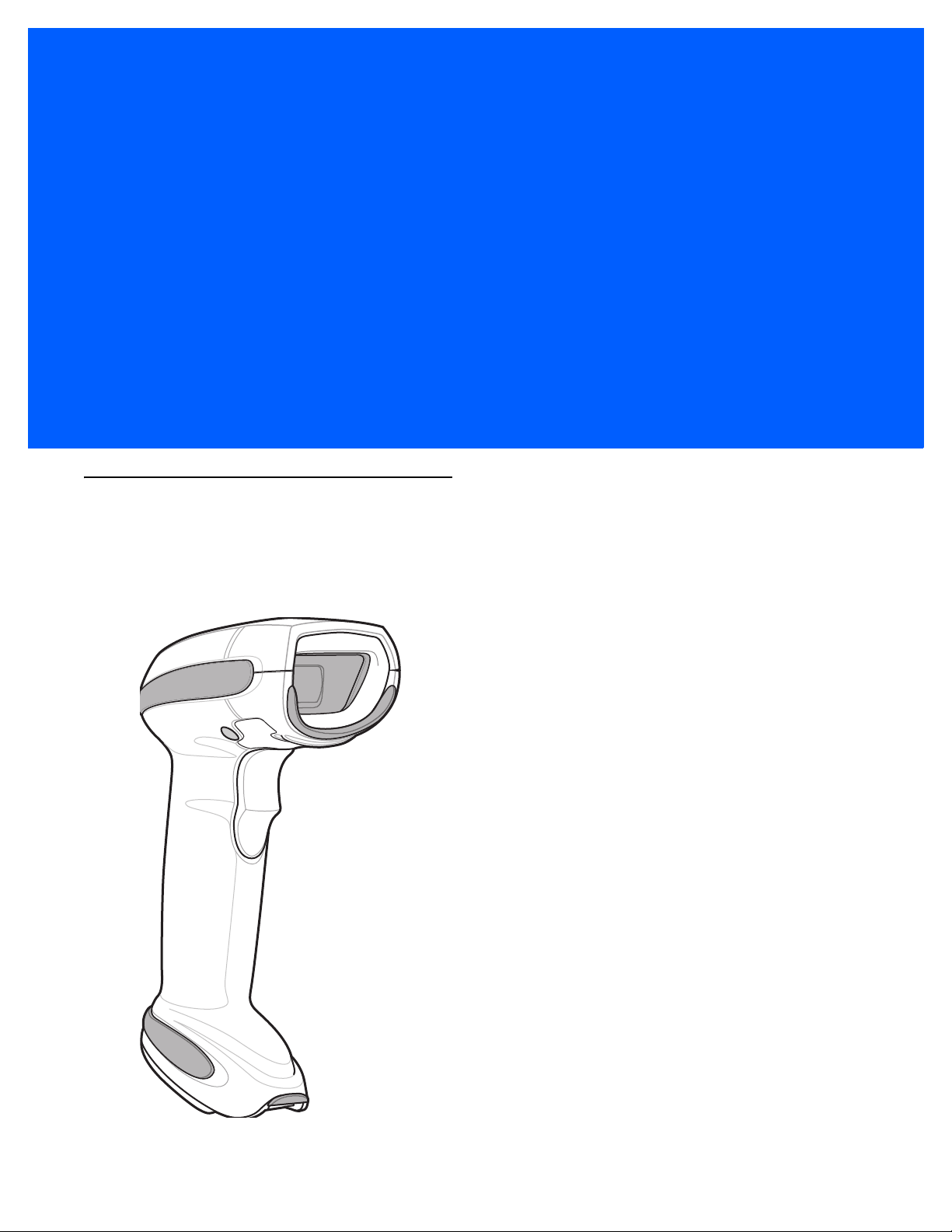
The world class LI4278 linear imager scanner, first in a family of high performance linear imagers from Zebra,
offers customers a cost effective, cordless 1D bar code scanner which out performs all existing linear imagers
and established Zebra as a leader in imager bar code readers.
Figure 1-1
LI4278 Linear Imager

1 - 2 LI4278 Product Reference Guide
Interfaces
The CR0078-S cradle supports all of the following interfaces. The CR0078-P cradle supports all of the below
listed interfaces with the exception of Wand Emulation, Scanner Emulation and Synapse.
Table 1-1
USB Connection to a Host
Standard RS-232
Connection to a Host
Keyboard Wedge
Connection to a Host
Connection to IBM®
468X/469X Hosts
Interface Support - CR0078-S / CR0078-P Cradles
Interface Description
The cradle auto detects a USB host and defaults to the HID
keyboard interface type. Select other USB interface types
by scanning programming bar code menus.This interface
supports the following international keyboards (for
Windows® environment): North America, German, French,
French Canadian, Spanish, Italian, Swedish, UK English,
Portuguese-Brazilian, and Japanese.
Scan bar code menus to set up proper communication of
the cradle with the host.
The host interprets scanned data as keystrokes. This
interface supports the following international keyboards
®
(for Windows
French, French Canadian, Spanish, Italian, Swedish, UK
English, Portuguese-Brazilian, and Japanese.
Scan bar code menus to set up communication of the
cradle with the IBM terminal.
environment): North America, German,
Cradle Support
CR0078-
S
XX
XX
XX
XX
CR0078-
P
Wand Emulation Connection
to a Host
Scanner Emulation
connection to a Host
Synapse Capability Allows connection to a wide variety of host systems using
Configuration via 123Scan
The cradle is connected to a portable data terminal, a
controller, or host which collects the data as wand data
and decodes it.
The cradle is connected to a portable data terminal, a
controller which collects the data and interprets it for the
host.
a Synapse and Synapse adapter cable. The cradle auto
detects the host.
PC-based software tool that enables rapid and easy
customized setup of Zebra scanners.
Unpacking the Linear Imager Scanner and Cradle
Remove the scanner and cradle from their respective packing and inspect for damage. If the scanner or cradle
was damaged in transit, contact Zebra Support. See page xxiii for contact information. KEEP THE PACKING.
It is the approved shipping container and should be used if the equipment ever needs to be returned for
servicing.
X
X
X
XX
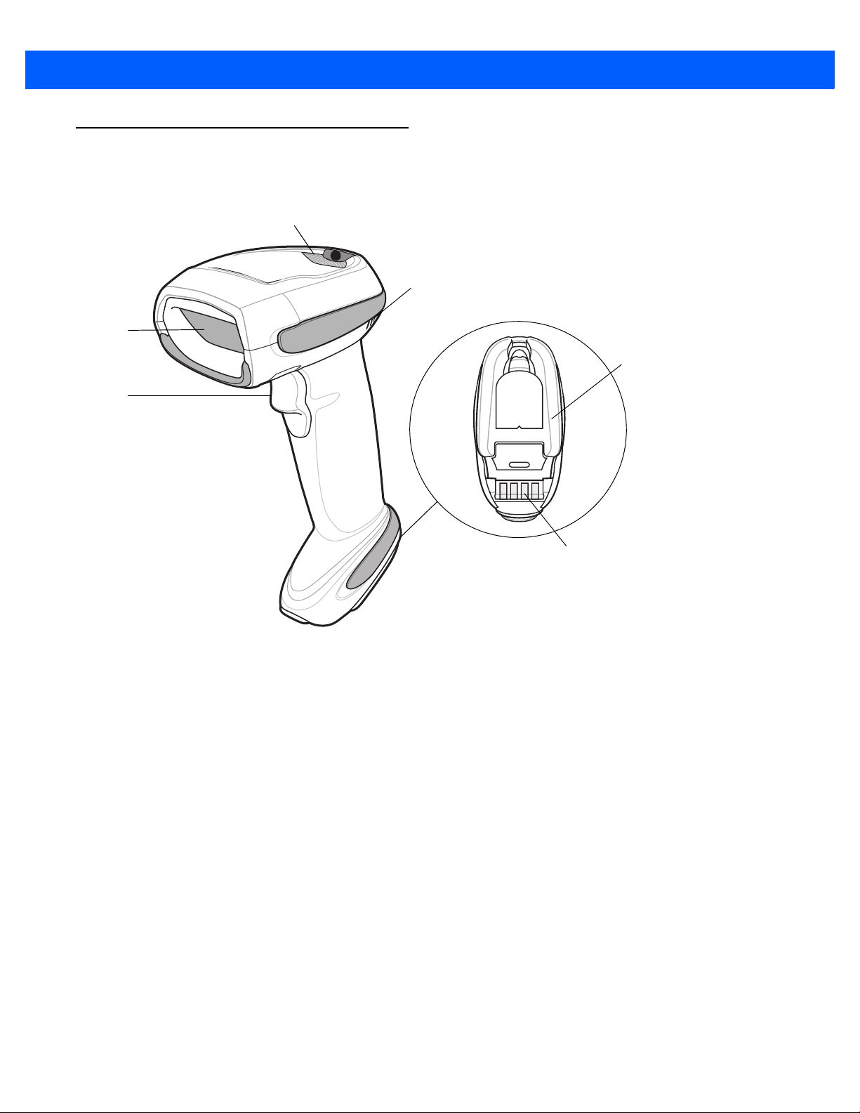
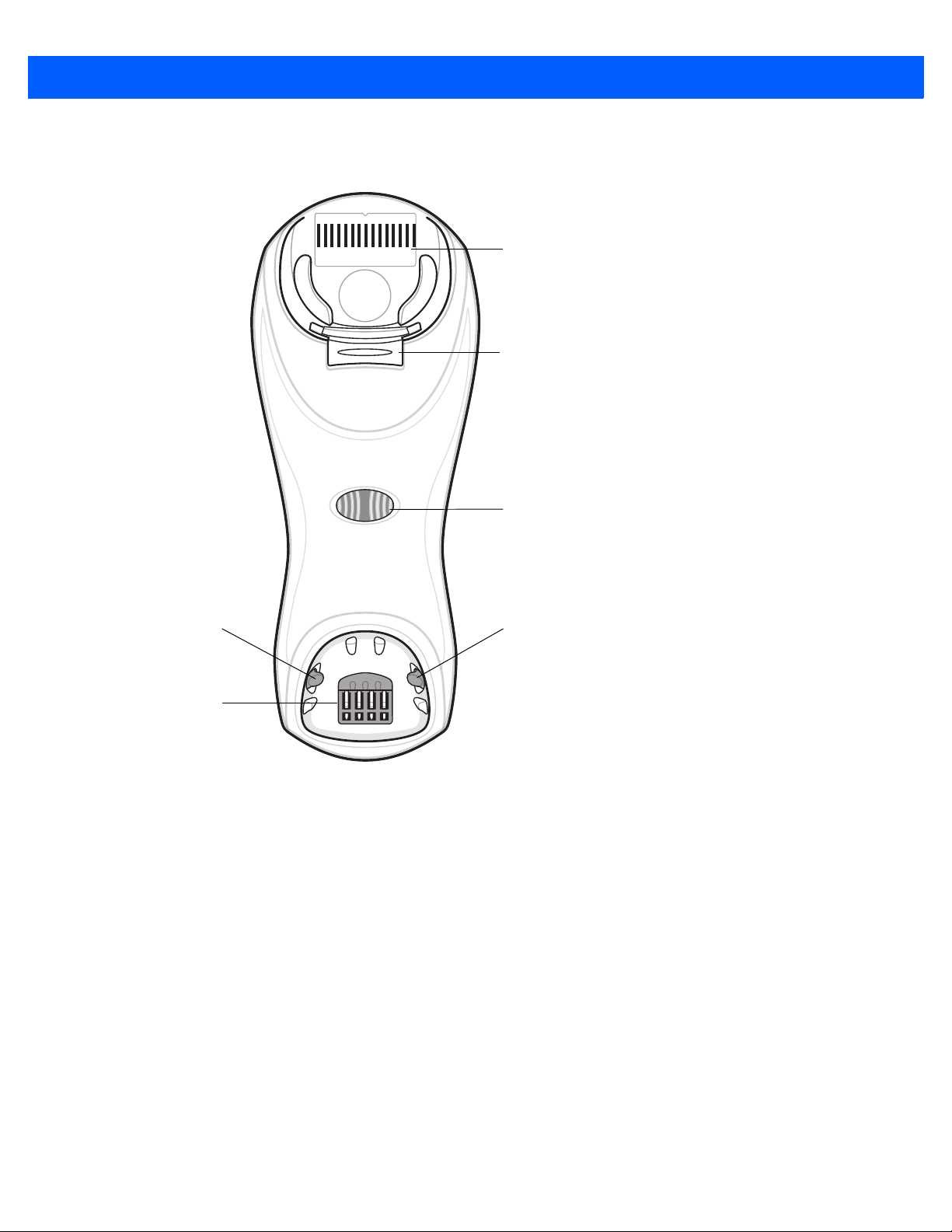
Parts
Beeper
LED
Trigger
Scan
Window
Battery Door
Metal Charging
Contacts
Scanner
GETTING STARTED 1 - 3
Figure 1-2
Parts of the Linear Imager Scanner
1 - 4 LI4278 Product Reference Guide
Pairing
Bar Code
(CR0078-S only)
Latch
Latch
Charging/
Communications
Contacts
Cradle Power
LED
Convertible
Mount Hook
(cradle serial #)
CR0078-S/CR0008-S Series Cradle
Figure 1-3
CR0078-S/CR0008-S Series Cradle Front View

GETTING STARTED 1 - 5
Rubber Foot Rubber Foot
Mounting Hole
Host Cable Groove
Rubber Foot
Rubber Foot
Power Port
Host Port
(Applies to CR0078-S
only)
Power Cable Groove
Desk/Wall Mount
Converter Knob
Mounting Hole
Power Cable Hook
Host Cable Hook
Figure 1-4
CR0078-S/CR0008-S Series Cradle Back View

1 - 6 LI4278 Product Reference Guide
Charging/
Communication
Contacts
Latch
LED
Page Button
Rubber Foot
Rubber Foot
Rubber Foot
Power Port
Host Port
Host Cable Groove
Power Cable
Groove
Host Cable Groove
Cable Support Hook
Cable Support Hook
Mounting Hole
Power Cable Groove
Rubber Foot
Mounting Hole
CR0078-P Series Cradle
Figure 1-5
Figure 1-6
CR0078-P Cradle Top View
CR0078-P Cradle Bottom View

Linear Imager Scanner Cradle
The scanner cradles (CR0078-S and CR0078-P) serve as a stand, charger, and host interface for the linear
imager scanner. The cradle sits on a desktop. The CR0078-S cradle can also be mounted on a vertical surface
(such as a wall). For more information about mounting options and procedures, refer to the documentation
included with the cradle.
The CR0078-S cradle is available as a charging cradle with a radio and as a charge-only cradle. The
CR0078-P cradle is only available as a charging cradle with a radio. The differences between the two versions
are as follows:
•
Charging cradle with radio: When the cordless linear imager scanner is paired to the cradle, all
communication between the linear imager scanner and the host computer is accomplished through the
cradle. Each bar code contains programming instructions or other data unique to the bar code pattern.
The linear imager scanner is paired to the cradle and transmits bar code data to the cradle via Bluetooth
Technology Profile Support. The cradle then sends that information via an interface cable to the host
computer for interpretation.
•
Charge-only cradle: This cradle serves as a stand and battery charger. It does not contain a radio and
has no communication capability.
GETTING STARTED 1 - 7
NOTE For more information about communication between the linear imager scanner, cradle and host, see
Chapter 4, RADIO COMMUNICATIONS.
Table 1-2 outlines several main differences between the CR0078-S and CR0078-P cradles.
Table 1-2
Scanning Hand-Held scanning Hands-Free or Hand-Held scanning
Bluetooth Bluetooth or Charge Only (CR0008-S) Bluetooth
Pairing Pair up to 3 scanners per cradle Pair up to seven scanners per cradle
Paging Not available Ability to page misplaced scanner(s)
Charging Can charge via host power, if available,
Interfaces Supports most commonly used interfaces
USB Cable Standard universal USB cable Requires universal cables with shielded
Cradle Features
Feature CR0078-S CR0078-P
Requires 12V power supply
or with optional 5V power supply.
Supports most commonly used interfaces
(see Technical Specifications on page 3-9
for detailed list)
with the exception of Wand Emulation,
Scanner Emulation and Synapse
modular plugs

1 - 8 LI4278 Product Reference Guide
Power Port
Host Port
Power Port
Host Port
Connect to appropriate host
Power
Connecting the CR0078-S/CR0008-S Series Cradle
IMPORTANTConnect the interface cable and power supply (if necessary) in the following order to ensure proper
operation of the linear imager scanner and cradle.
1. If a power supply is connected to the cradle, disconnect it. See Figure 1-7.
2. If using an interface cable (CR0078-S only), insert the cable into the cradle’s host port.
3. If using a power supply that connects to the interface cable (CR0078-S only), insert this power supply into
the power connector on the interface cable, and the other end to an AC supply.
4. Insert the other end of the interface cable into the appropriate port on the host computer (see the specific
host chapter for information on host connections).
5. If using an external power supply (if required by the interface, or to allow fast charging of the linear imager
scanner), insert the power cable into the power port on the back of the cradle, and connect the power
supply to an approved AC supply (refer to the CR0078-S/CR0008-S Cradle Quick Reference Guide for
more information).
Figure 1-7
6. If applicable, thread the interface cable over the cable support hook and run the host and power cables into
Connecting the Cables to the CR0078-S/CR0008-S Cradle
their respective cable grooves.
7. Mount the cradle, as necessary. (For information on mounting the cradle, refer to the documentation
included with the cradle.)
NOTE Disconnect the power supply before changing host cables, or the cradle may not recognize the new host.
Different cables are required for different hosts. The connectors illustrated in each host chapter are
examples only. The connectors may be different from those illustrated, but the steps to connect the cradle
remain the same.
Supplying Power to the CR0078-S/CR0008-S Cradle
The CR0078-S/CR0008-S cradle receives power from one of two sources:
•
An external power supply.
•
When connected to the host through a host cable that supplies power (CR0078-S only).
The cradle detects whether the host or the external supply is supplying power. It always draws power from the
external supply when available, regardless of the presence of power from a host.
When the CR0078-S cradle is connected to the host via the USB interface, it can be powered by the USB port
instead of an external power supply. Powering from a USB host limits charging. The linear imager scanner
charges at a slower rate than when charging from an external power supply.

GETTING STARTED 1 - 9
Power Port
Host Port
Power Port
Host Port
Connect to appropriate host
Power
Alternate Host Groove
Alternate Power Groove
Connecting the CR0078-P Series Cradle
IMPORTANTConnect the interface cable and power supply in the following order to ensure proper operation of
the linear imager scanner and cradle.
1. Insert the interface cable into the cradle’s host port.
2. Connect the other end of the interface cable to the host.
3. Connect the power supply to the cradle’s power port.
4. Connect the appropriate cable to the power supply and AC power source.
5. Thread the interface cable over the cable support hook (see Chapter 1-6, CR0078-P Cradle Bottom View)
and run the host and power cables into their respective cable grooves.
6. If necessary, (for non-autodetected interfaces) scan the appropriate host bar code (refer to the
CR0078-S/CR0008-S Cradle Quick Reference Guide for more information).
Figure 1-8
Connecting the Cables to the CR0078-P Cradle
Supplying Power to the CR0078-P Cradle
The CR0078-P cradle receives power from an external power supply.
NOTE The CR0078-S cradle has the ability to be powered by the host instead of an external power supply. The
CR0078-P can only receive power via an external power supply.
It is always recommended that an external power supply be used to provide fastest recharge times.

1 - 10 LI4278 Product Reference Guide
Lost Connection to Host
If scanned data does not transmit to the cradle’s host, ensure that all cables are firmly inserted and the power
supply is connected to an appropriate AC outlet. If scanned data still does not transmit to the host, reestablish
a connection with the host:
1. Disconnect the power supply from the cradle.
2. Disconnect the host interface cable from the cradle.
3. Wait three seconds.
4. Reconnect the host interface cable to the cradle.
5. Reconnect the power supply to the cradle, if required.
6. Reestablish pairing with the cradle by scanning the pairing bar code.
NOTE The CR0078-S does not always require a power supply whereas the CR0078-P always requires a power
supply.
Mounting the Cradle
For information on mounting the CR0078-S cradle, refer to the documentation included with the cradle.

Replacing the Linear Imager Scanner Battery
11
54
32
6
Battery Connector
Clip
The battery is installed in the cordless linear imager scanner by the factory and resides in a chamber in the
linear imager scanner handle. To replace the battery:
1. Insert a Phillips screwdriver in the screw at the base of the linear imager scanner, then turn the screw
counterclockwise to release the latch.
2. Remove the latch.
3. If a battery is already installed, turn the linear imager scanner upright to slide the battery out. Disconnect
the battery connector clip.
GETTING STARTED 1 - 11
Figure 1-9
4. With the contacts on the connector clips facing in the same direction, attach the new battery’s connector
Inserting the Battery
clip to the connector clip in the base of the linear imager scanner.
5. Slide the new battery into the battery well and ensure the battery leads are visible. The battery should sit
securely in the well.
6. Attach and close the latch.
7. Insert a Phillips screwdriver in the screw at the base of the linear imager scanner, press down gently, and
turn the screw clockwise to lock the latch in place.

1 - 12 LI4278 Product Reference Guide
Charging the Linear Imager Scanner Battery
Fully charge the linear imager scanner battery before using the linear imager scanner for the first time. To
charge the linear imager scanner battery, place the linear imager scanner in the cradle, ensuring that the metal
contacts on the bottom of the linear imager scanner touch the contacts on the cradle. A complete charge of a
fully discharged battery can take typically three hours using external power and typically five hours when
powered from a host.
For battery charging LED indicators see Table 1-3 and Table 2-2 on page 2-5. See Table 1-4 on page 1-13 for
battery reconditioning LED indicators.
CAUTION To avoid a battery temperature fault, always charge the battery in the linear imager scanner within the
recommended temperature of 32° to 104° F (0° to 40° C) nominal, 41° to 95° F (5° to 35° C) ideal.
Table 1-3
LED Indication Indication
Green - Slow
Continuous Flash
Red & Green Continuous Flash
Green - Fast
Continuous Flash
Green - Solid Linear imager scanner is fully charged.
Red Battery may require pre-charge.
Charging LED Definitions
Non-critical battery temperature fault. Battery is above or below normal operating
temperature.
If this occurs, do not use the linear imager scanner and move the linear imager scanner to a
location within normal operating temperature. The linear imager scanner can remain in the
cradle while the battery warms or cools to normal operating temperature.
Note: For appropriate charging temperatures, see
Critical battery temperature fault. Battery is above or below normal operating temperature.
If this occurs, do not use the linear imager scanner and move the linear imager scanner to a
location within normal operating temperature. The linear imager scanner can remain in the
cradle while the battery warms or cools to normal operating temperature.
Note: For appropriate charging temperatures, see
Linear imager scanner is charging.
Table 3-3 on page 3-10
Table 3-3 on page 3-10
.
.
Turning Off the Linear Imager Scanner Battery
To turn off the NiMH battery for long term storage or shipping:
1. Scan Battery Off bar code below.
Battery Off
2. To turn the battery back on, place the linear imager scanner in the cradle.

Reconditioning the Linear Imager Scanner Battery
To maintain optimal performance of the linear imager scanner NiMH battery, perform a battery recondition
approximately once a year.
To begin the battery recondition cycle:
1. Scan Battery Recondition below.
Battery Recondition
2. Place the linear imager scanner into the cradle.
NOTE If the scanner is removed from the cradle during the battery reconditioning cycle, the scanner exits the
battery reconditioning mode of operation and returns to the normal mode of battery charging (see
Charging the Linear Imager Scanner Battery on page 1-12). To restart the battery reconditioning cycle,
re-scan the Battery Recondition parameter and place the scanner in the cradle.
GETTING STARTED 1 - 13
3. The linear imager scanner must perform two charge cycles to complete the battery reconditioning process
(discharge/charge/discharge/charge). See Table 1-4.
Battery Reconditioning LED Definitions
Table 1-4
Reconditioning Mode
Discharging Red Flash Time to discharge is approximately 2.5 hours.
Charging Green Flash Time to charge is typically 3 hours with an external
Reconditioning Complete Green - Solid (always on) The linear imager scanner enters a trickle charge until
Note: When the scanner is inserted into the CR0078-S (standard) cradle, the scanner's LED is
Battery Reconditioning LED Definitions
Battery
used as the charging indicator.
When the scanner is inserted into the CR0078-P (presentation) cradle, the cradle's LED is
used as the charging indicator.
LED Comments
power supply.
the linear imager scanner is removed from the cradle.

1 - 14 LI4278 Product Reference Guide
Desk/Wall Mount
Converter Knob
Inserting the Linear Imager Scanner in the Cradle
Insert the linear imager scanner in the cradle so that the metal contacts on the bottom of the linear imager
scanner handle touch the contacts on the cradle. Push the handle lightly to ensure a proper connection,
engaging the contacts in the cradle and linear imager scanner. Ensure the desk/wall mount converter knob on
the back of the cradle is in the correct position for the horizontal or vertical mounting.
NOTE References to mounting the cradle only apply to the CR0078-S/CR0008-S cradle (not the CR0078-P
cradle).
Inserting Linear Imager Scanner in the CR0078-S/CR0008-S Cradle
Horizontal Cradle Mount
When mounting the cradle horizontally, where no fastening is necessary:
1. Ensure the rubber feet are attached to the cradle. These feet provide traction and prevent surface damage.
2. Ensure the desk/wall mount converter knob is in the position shown in Figure 1-10.
Figure 1-10
Horizontal Mount - Inserting the Linear Imager Scanner in the Cradle
Vertical Cradle Mount
When mounting the cradle vertically:
1. Ensure the rubber feet are attached to the cradle. These feet provide traction and prevent surface damage.
2. Ensure the convertible mount hook on the front of the cradle is inserted with the hook facing up. If not,
remove and reverse the hook so that it is in position to secure the linear imager scanner in place. (See
Figure 1-3 on page 1-4 for the location of the convertible mount hook.)

GETTING STARTED 1 - 15
Desk/Wall
Mount
Converter Knob
Click
1
2
3. Ensure the desk/wall mount converter knob is in the position shown in Figure 1-11.
Figure 1-11
Vertical Mount - Inserting the Linear Imager Scanner in the Cradle
Inserting/Removing Linear Imager Scanner in the CR0078-P Cradle
To insert the scanner in the Presentation Cradle:
1. Insert the scanner by placing the bottom of the scanner, at a slight forward angle, into the CR0078-P
cradle.
2. Push the handle back and down until it clicks, engaging the contacts of the scanner and cradle.
Figure 1-12
Inserting the Linear Imager Scanner in the Presentation Cradle
To remove the scanner from the Presentation Cradle:
1. Remove the scanner by pushing the scanner slightly forward and up out of the CR0078-P cradle.

1 - 16 LI4278 Product Reference Guide
1
2
Click
Figure 1-13
Removing the Linear Imager Scanner in the Presentation Cradle

Wall Mount Bracket Template
7.55 in. (191.77mm)
1.7 in. (43.18mm)
NOTE Cradle mounting only applies to the
CR0078-S/CR0008-S cradle (not the CR0078-P
cradle). For detailed instructions on mounting the
cradle, refer to the CR0078-S/CR0008-S Quick
Reference Guide (p/n 72-135874-xx).
For your convenience, a wall mount bracket can be purchased from Zebra. Use the mounting holes on the Wall
Mount Bracket or use the template in Figure 1-14 to determine the location of the screw holes.
GETTING STARTED 1 - 17
Figure 1-14
Wall Mount Bracket Template
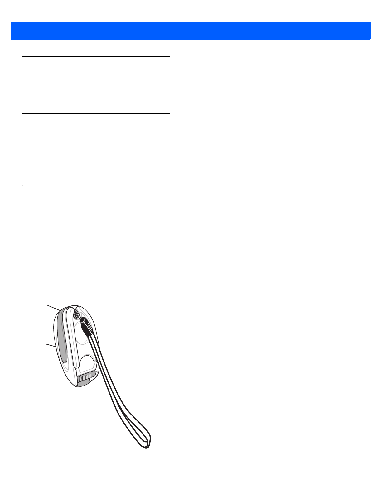
1 - 18 LI4278 Product Reference Guide
Radio Communications
The linear imager scanner can communicate with remote devices via Bluetooth Technology Profile Support, or
by pairing with a cradle. For radio communication parameters, detailed information about operational modes,
Bluetooth Technology Profile Support and pairing, see Chapter 4, RADIO COMMUNICATIONS.
Configuring the Linear Imager Scanner
Use the bar codes in this manual or the 123Scan configuration program to configure the linear imager scanner.
See Chapter 5, USER PREFERENCES & MISCELLANEOUS SCANNER OPTIONS for information about
programming the linear imager scanner using bar code menus. Also see each host-specific chapter to set up
connection to a specific host type. See Chapter 10, 123SCAN2 to configure the linear imager scanner using
this configuration program.
Accessories
The linear imager scanner and cradle accessories that are available separately include:
•
Power supplies for applications that do not supply power over the host cable. See each host interface
chapter for set up information.
•
Wall-mount bracket for mounting the cradle vertically. Refer to the CR0078-S/CR0008-S Cradle Quick
Reference Guide (p/n 72-135874-xx) for a wall mounting template and installation instructions.
•
Lanyard for wearing the linear imager scanner on a wrist.
Lanyard
The lanyard attaches to the inside of the linear imager scanner battery door latch.
Figure 1-15
Attached Lanyard

GETTING STARTED 1 - 19
Battery Door
Latch
Loop Guides
Screw Container
To attach the lanyard:
1. Open the battery door latch as described in Replacing the Linear Imager Scanner Battery on page 1-11.
Do not remove the battery.
2. Hook the loop of the lanyard around the screw container inside the battery door latch, between the loop
guides.
Figure 1-16
3. Close the battery door latch.
4. Tighten the screw.
Attaching Lanyard

1 - 20 LI4278 Product Reference Guide

CHAPTER 2SCANNING
Introduction
This chapter provides beeper and LED definitions, scanning techniques, general instructions and tips about
scanning, and decode ranges.
Beeper and LED Definitions
The linear imager scanner issues different beep sequences/patterns and an LED display to indicate status.
Table 2-1 defines beep sequences/patterns and LED displays which occur during both normal scanning and
while programming the linear imager scanner. (Also seeTable 1-3 on page 1-12 and Table 1-4 on page 1-13 for
charging and battery reconditioning LED indicators.)
Table 2-1
Beeper Sequence LED Indication Indication
Standard Use
Low/medium/high beeps None Power up.
Scanning
None Green Solid Presentation Mode on.
None No LED; green LED is
Medium beep
(or as configured)
Low/low/low/extra low
beeps
Scanner Beeper and LED Definitions
Presentation Mode off.
turned off
Green Flash A bar code was successfully decoded. (See
5-1, User Preferences Parameter Defaults
programming beeper sounds.)
Red Parity error.
Chapter
for

2 - 2 LI4278 Product Reference Guide
Table 2-1
Beeper Sequence LED Indication Indication
Four long low beeps Red 1. A transmission error was detected in a scanned
Four short high beeps None Low battery warning.
Five long low beeps Red Conversion or format error.
Long low/long high/long
low/long high beeps
Wireless Operation
Low beep None Linear imager scanner detects power when inserted into
Scanner Beeper and LED Definitions (Continued)
symbol. The data is ignored. This occurs if a unit is not
properly configured. Check option setting.
2. When communicating with a cradle, the cradle
acknowledges receipt of data. If the acknowledgment is
not received, this transmission error beep sequence
sounds. Data may still have been received by the host.
Check the host system for receipt of transmitted data. If
data was not received by the host, re-scan the bar code.
Red Out of memory - unable to store a new bar code.
a cradle.
Note: This feature is enabled by default and can be
disabled (see
Beep on Insertion on page 4-20
).
Long low/long high/long
low/long high beeps
High/low/high/low beeps None Pairing bar code scanned.
Low/high beeps None Bluetooth connection established.
High/low beeps None Bluetooth disconnection event.
Long low/long high beeps Red Page timeout; remote device is out of range/not
Five high beeps
(only when configured)
Red Cradle is out of batch storage memory, unable to store
new bar code.
Note: When connected to a remote device using SPP or
HID, if a disconnect beep sequence sounds immediately
after a bar code is scanned, check the host device for
receipt of transmitted data. It is possible that an attempt
was made to transmit the last bar code scanned after
the connection was lost.
powered. (See
Green Blinking 1. Bluetooth attempting reconnection.
2. Emitted every 5 seconds while a reconnection
attempt is in progress. (See
Feature on page 4-15
Auto-reconnect Feature on page 4-15
Auto-reconnect
.)
.)

SCANNING 2 - 3
Table 2-1
Beeper Sequence LED Indication Indication
Long low/long high/long
low/long high beeps
Parameter Programming
Long low/long high beeps Red Input error, incorrect bar code or
High/low beeps Green Keyboard parameter selected. Enter value using bar
High/low/high/low beeps Green Successful program exit with change in the parameter
ADF Programming
Scanner Beeper and LED Definitions (Continued)
None Connection attempt was rejected by remote device.
Note: In the case of
cradle may already be connected to another linear
imager scanner in single Point-to-Point locked mode, or
the piconet may be full in Multipoint-to-Point mode. If
Pair On Contacts is enabled and the linear imager
scanner that is inserted is already connected to the
cradle, no beeping occurs.
wrong entry, incorrect bar code programming
sequence; remain in program mode.
code keypad.
setting.
Pairing Methods on page 4-24
Cancel
scanned,
, the
Low/high/low beeps None ADF transmit error.
High/low beeps Green Number expected. Enter another digit. Add leading
zeros to the front if necessary.
Low/low beeps Green Alpha expected. Enter another alphabetic character or
scan the
High/high beeps Green Blinking ADF criteria or action is expected. Enter another criteria
or action or scan the
High/low/low beeps Green All criteria or actions cleared for current rule, continue
entering rule.
High/low/high/low beeps Green
(turns off blinking)
Long low/long high beeps Red Rule error. Entry error, wrong bar code scanned, or
Low beep Green Deleted last saved rule. The current rule is left intact.
Low/high/high beeps Green All rules deleted.
Long low/long high/long
low/long high beeps
Red Out of rule memory. Erase some existing rules, then try
Rule saved. Rule entry mode exited.
criteria/action list is too long for a rule. Re-enter criteria
or action.
to save rule again.
End of Message
Save Rule
bar code.
bar code.
Long low/long high/long
low beeps
Code 39 Buffering
High/low beeps None New Code 39 data was entered into the buffer.
Green
(turns off blinking)
Cancel rule entry. Rule entry mode exited because of an
error or the user asked to exit rule entry.

2 - 4 LI4278 Product Reference Guide
Table 2-1
Beeper Sequence LED Indication Indication
Three long high beeps None Code 39 buffer is full.
High/low/high beeps None The Code 39 buffer was erased/cleared.
Low/high/low beeps None The Code 39 buffer was erased or there was an attempt
Low/high beeps None A successful transmission of buffered data.
Host Specific
USB only
Four high beeps None Linear imager scanner has not completed initialization.
RS-232 only
High/high/high/low beeps Red RS-232 receive error.
High beep None A <BEL> character is received when Beep on <BEL> is
Scanner Beeper and LED Definitions (Continued)
to clear or transmit an empty buffer.
Wait several seconds and scan again.
enabled (Point-to-Point mode only).

Cradle LED Definitions
IMPORTANTWhen the scanner is inserted into the CR0078-S (standard) cradle, the scanner's LED is used as the
charging indicator.
When the scanner is inserted into the CR0078-P (presentation) cradle, the cradle's LED is used as
the charging indicator.
NOTE The CR0078-S/CR0008-S cradles’ LED indicate power only.
SCANNING 2 - 5
Table 2-2
CR0078-P Cradle LED Definitions
LED Indication
Green Blinking Cradle is externally powered and connected to a USB host interface which has
suspended the cradle. The cradle is no longer connected to the linear imager
scanner but it will charge the linear imager scanner. Scan the pairing bar code to
pair the scanner and cradle (see
Pairing on page 4-22
).
Red Blinking Transmission error.
Green Cradle is powered.
Red Blinking Transmission error.
Green Slow Blinking Non-critical battery temperature fault.
Green Slow Blinking Charging in cradle with USB (bus powered).
Green Fast Blinking The scanner is charging.
Amber Blinking Critical battery temperature fault.
Green Solid The scanner is fully charged.
Red Solid Battery requires precharge.
Red Slow Blinking Battery is reconditioning.

2 - 6 LI4278 Product Reference Guide
Scanning
To program the linear imager scanner, see the appropriate host chapter, Chapter 4, RADIO
COMMUNICATIONS and Chapter 11, SYMBOLOGIES. (In addition to the parameters included in the chapters
mentioned, user preference and miscellaneous linear imager scanner option parameters are also available in
this guide.)
Aiming
When scanning, the linear imager scanner projects a red illumination which allows positioning the bar code
within its field of view. See Decode Ranges on page 2-8 for the proper distance to achieve between the linear
imager scanner and a bar code.
Hand-Held Scanning
To scan:
1. Ensure all connections are secure (see appropriate host chapter).
2. Aim the linear imager scanner at the bar code.
3. Press the trigger.
Figure 2-1
4. Upon successful decode, the linear imager scanner beeps and the LED displays a single green flash. (For
more information about beeper and LED definitions, see Table 2-1 and Table 2-2.)
Scanning

SCANNING 2 - 7
Hands-Free Scanning
The linear imager scanner is in hands-free (presentation) mode when it sits in the CR0078-P cradle. In this
mode the linear imager scanner operates in continuous (constant-on) mode, where it automatically decodes a
bar code presented in the field of view. The scanner LED is on, solid green
To scan:
1. Ensure all connections are secure (see appropriate host chapter).
2. Present the bar code in the linear imager scanner field of view.
Figure 2-2
3. Upon successful decode, the linear imager scanner beeps and the green LED momentarily turns off. (For
more information about beeper and LED definitions, see Table 2-1 and Table 2-2.)
Presentation Scanning

2 - 8 LI4278 Product Reference Guide
Decode Ranges
Ranges are calculated on Code 39 except where noted.
Table 2-3
Symbol Density Bar Code Type
100 mil (paper) > 20 ft. (> 6 m)
LI4278 Decode Ranges
Typical Working Ranges
Near Far
4 mil Code 39
5 mil Code 39 3.0 in. (7.6 cm) 13.0 in. (33.0 cm)
7.5 mil
13 mil 100% UPC-A 1.0 in. (2.5 cm) 31.0 in. (78.7 cm)
20 mil
26 mil 200% UPC-A
NOTE When reading high density bar codes, users should attempt to read them slightly farther away from the
scanner. Typically a 3 mil Code39 bar code begins reading at 5 in. (12.8cm).
Code 39 1.5 in. (3.8 cm) 19.0 in. (48.3 cm)
Code 39 1.0 in. (2.5 cm) 42.0 in. (106.7 cm)
4
in. (10.2 cm) 10.0 in. (25.4 cm)
3.0 in. (7.6 cm) 55.0 in. (140.0 cm)

CHAPTER 3MAINTENANCE,
TROUBLESHOOTING &
TECHNICAL
SPECIFICATIONS
Introduction
This chapter provides suggested linear imager scanner and cradle maintenance, troubleshooting, technical
specifications, and signal descriptions (pinouts).
Maintenance
Known Harmful Ingredients
The following chemicals are known to damage the plastics on Zebra scanners/cradles and should not come in
contact with the device:
•Acetone
• Ammonia solutions
• Aqueous or alcoholic alkaline solutions
• Aromatic and chlorinated hydrocarbons
• Benzene
•Bleach
• Carbolic acid
• Compounds of amines or ammonia
• Ethanolamine
• Ethers
• Ketones
•TB-lysoform
• Toluene
• Trichloroethylene.

3 - 2 LI4278 Product Reference Guide
Approved Cleaning Agents
The following cleaning agents are approved for cleaning the plastics on Zebra scanners/cradles:
• Pre-moistened wipes
• Isopropyl alcohol 70%
Cleaning the Linear Imager Scanner
CAUTION Avoid using cleansers directly on the linear imager scanner battery door and contacts. Use a cotton
swab moistened with alcohol to gently clean contacts.
Routinely cleaning the exit window is required. A dirty window may affect scanning accuracy. Do not allow any
abrasive material to touch the window.
To clean the scanner:
1. Dampen a soft cloth with one of the approved cleaning agents listed above or use pre-moistened wipes.
2. Gently wipe all surfaces, including the front, back, sides, top and bottom. Never apply liquid directly to the
scanner. Be careful not to let liquid pool around the scanner window, trigger, cable connector or any other
area on the device.
3. Be sure to clean the trigger and in between the trigger and the housing (use a cotton-tipped applicator to
reach tight or inaccessible areas).
4. Do not spray water or other cleaning liquids directly into the exit window.
5. Wipe the scanner exit window with a lens tissue or other material suitable for cleaning optical material such
as eyeglasses.
6. Immediately dry the scanner window after cleaning with a soft non-abrasive cloth to prevent streaking.
7. Allow the unit to air dry before use.
8. Scanner connectors:
a. Dip the cotton portion of a cotton-tipped applicator in isopropyl alcohol.
b. Rub the cotton portion of the cotton-tipped applicator back-and-forth across the connector on the
Zebra scanner at least 3 times. Do not leave any cotton residue on the connector.
c. Use the cotton-tipped applicator dipped in alcohol to remove any grease and dirt near the connector
area.
d. Use a dry cotton tipped applicator and rub the cotton portion of the cotton-tipped applicator
back-and-forth across the connectors at least 3 times. Do not leave any cotton residue on the
connectors.
Cleaning the Linear Imager Scanner Cradles
CAUTION Avoid using cleansers directly on the linear imager scanner cradle contacts. Use a cotton swab
moistened with alcohol to gently clean contacts.
Do not pour, spray or spill any liquid on the cradle. See Cleaning the Linear Imager Scanner for instructions
about cleaning the cradles.
To clean the cradle connectors:
1. Remove the DC power cable from the cradle.

MAINTENANCE, TROUBLESHOOTING & TECHNICAL SPECIFICATIONS 3 - 3
2. Dip the cotton portion of a cotton-tipped applicator in isopropyl alcohol.
3. Rub the cotton portion of the cotton-tipped applicator along the pins of the connector. Slowly move the
applicator back-and-forth from one side of the connector to the other. Do not let any cotton residue remain
on the connector.
4. Rub all sides of the connector with the cotton-tipped applicator.
5. Spray compressed air in the connector area by pointing the tube/nozzle approximately 1/2 inch (1 cm)
away from the surface.
CAUTION When using compressed air, always wear eye protection; do not point nozzle at yourself or
others; make sure the nozzle or tube is pointing away from your face; read warning label on
compressed air product.
a. Ensure that there is no lint left by the cotton tipped applicator. Remove lint if found.
b. If grease and other dirt are found on other areas of the cradle, use a lint free cloth and isopropyl
alcohol to remove.
c. Allow at least 10 to 30 minutes (depending on ambient temperature and humidity) for the isopropyl
alcohol to air dry before applying power to cradle.
NOTE If the temperature is low and humidity is high, longer drying time is required. Warm temperature
and low humidity requires less drying time.
Battery Information
Rechargeable battery packs are designed and constructed to the highest standards within the industry.
However, there are limitations to how long a battery can operate or be stored before needing replacement.
Many factors affect the life of a battery pack such as heat, cold, customer usage profiles, age and severe
drops.
When batteries are stored over a year, battery cell manufacturers advise that some irreversible deterioration in
overall battery quality may occur. To minimize this loss, they recommend storing batteries half charged in a dry,
cool place between 41° F and 77° F (5° C and 25° C), the cooler the better, and removed from the equipment
to prevent the loss of capacity. Batteries should be charged to half capacity at least once a year. If an
electrolyte leakage is observed, avoid any contact with the affected area and properly dispose of the battery.
Replace the battery when a significant loss of run time is detected. Batteries must be charged within the 32° F
to 104° F (0° C to 40°C) temperature range.
The standard warranty period for all Zebra batteries is 30 days, regardless if the battery was purchased
separately or included as part of the linear imager scanner. For more information on batteries, please visit:
www.zebra.com/support.

3 - 4 LI4278 Product Reference Guide
Troubleshooting
NOTE See Dump Scanner Parameters on page 5-24 to debug scanner problems by creating a text file with all
the scanner's asset tracking information, and parameter settings.
If after performing the possible solutions in Table 3-1 the symbol still does not scan, contact the distributor
or contact the Zebra Global Customer Support Center. See page xxiii for contact information.
Table 3-1
Battery
Linear imager scanner battery
requires frequent charging.
Linear imager scanner displays solid
red LED longer than 3 seconds
when placed in cradle.
Beeper Indications
Linear imager scanner emits
low/high/low beeps.
Troubleshooting
Problem Possible Causes Possible Solutions
Battery may need reconditioning. Restore the battery by performing a
battery reconditioning cycle. See
Reconditioning the Linear Imager
Scanner Battery on page 1-13
more information.
Battery may require pre-charge
due to excessive discharge.
ADF transmit error. See
Invalid ADF rule is detected. See
Wait for the red LED to turn green
indicating that the scanner has begun
normal charging. Recommend allowing
battery to fully recharge.
FORMATTING
ADF programming.
FORMATTING
ADF programming.
Chapter 12, ADVANCED DATA
for information about
Chapter 12, ADVANCED DATA
for information about
for
Linear imager scanner emits a
low/high/low/high beep sequence
while it is being programmed.
Linear imager scanner emits long
low/long high beeps.
The Code 39 buffer was erased or
there was an attempt to clear or
transmit an empty buffer.
Out of ADF parameter storage
space.
Input error, incorrect bar code or
Cancel
Page timeout; remote device is
out of range/not powered.
bar code was scanned.
Normal when scanning the Code 39
Buffering
upon attempt to transmit an empty
Code 39 buffer.
Erase all rules and re-program with
shorter rules.
Scan the correct numeric bar codes
within range for the parameter
programmed.
Move the linear imager scanner back
into range of the remote device; try to
re-connect; check remote device
configuration.
Clear Buffer
bar code or

MAINTENANCE, TROUBLESHOOTING & TECHNICAL SPECIFICATIONS 3 - 5
Table 3-1
Linear imager scanner emits long
low/long high/long low/long high
beeps.
Linear imager scanner emits
high/high/high/low beeps.
Linear imager scanner emits
high/low beeps.
Troubleshooting (Continued)
Problem Possible Causes Possible Solutions
Out of host parameter storage
space.
Out of memory for ADF rules. Reduce the number of ADF rules or the
Connection attempt was rejected
by remote device.
RS-232 receive error. Normal during host reset. Otherwise,
The linear imager scanner is
buffering Code 39 data.
Or
Keyboard parameter selected.
Bluetooth disconnection event. Move the linear imager scanner back
Scan
Default Parameters on page
5-4
.
number of steps in the ADF rules.
Free up remote device resources.
set the linear imager scanner's RS-232
parity to match the host setting.
Normal.
Or
Enter value using bar code keypad.
into range of the remote device.
In Central (SPP) mode, re-pair the
linear imager scanner and cradle by
scanning the
cradle; check cradle power.
In Peripheral (SPP/HID) mode,
reestablish connection between the
linear imager scanner and remote
device from the remote device side.
PAIR
bar code on the
Linear imager scanner emits three
long high beeps.
Linear imager scanner emits four
high beeps on trigger release.
Linear imager scanner emits four
long low beeps.
Code 39 buffer is full. Scan the Code 39 bar code without a
leading space or scan
Code 39
& Store on page 11-32
stored Code 29 data.
Low battery. Place linear imager scanner in cradle
to charge the battery.
A transmission error was
detected in a scanned symbol.
The data is ignored.
The linear imager scanner is
either:
- Out of range
- Not paired to the cradle
- Not connected to a remote
Bluetooth device.
Acknowledgment that transmitted
data was not received by the
cradle.
This occurs if a unit is not properly
configured. Check option setting.
Move the linear imager scanner back
into range of the remote device.
Or
Scan the
Data may have been received by the
host. Check the host system for receipt
of transmitted data. If data was not
received by the host, re-scan the bar
code.
on
Code 39 Buffering - Scan
PAIR
bar code on the cradle.
Do Not Buffer
to transmit

3 - 6 LI4278 Product Reference Guide
Table 3-1
Linear imager scanner emits five low
long beeps.
Linear imager scanner emits a
power-up beep after scanning a
USB device type.
Power-up beep occurs more than
once.
Decoding Bar Codes
Linear imager scanner projects red
illumination, but does not decode the
bar code.
Troubleshooting (Continued)
Problem Possible Causes Possible Solutions
Conversion or format error. Check ADF rules for the host.
Communication with the bus was
not established.
The host PC performed a cold
boot.
Linear imager scanner is not
programmed for the correct bar
code type.
Bar code symbol is unreadable. Scan test symbols of the same bar
Communication with the bus must be
established before the linear imager
scanner can operate at the highest
power level.
The USB bus may put the linear imager
scanner in a state where power to the
linear imager scanner is cycled on and
off more than once. This is normal and
usually happens when the host PC
cold boots.
Program the linear imager scanner to
read that type of bar code. See
Chapter 11, SYMBOLOGIES
code type to determine if the bar code
is defaced.
.
Linear imager scanner decodes bar
code, but does not transmit the data
to the host.
Distance between linear imager
scanner and bar code is incorrect.
The scan line is not crossing
every bar and space of the
symbol.
Linear imager scanner is not
programmed for the correct host
type.
Interface cable is loose. Ensure all cable connections are
Cradle is not programmed for the
correct host interface.
Linear imager scanner not paired
to host-connected interface.
Cradle has lost connection to
host.
Move the linear imager scanner closer
to or further from the bar code. See
Decode Ranges on page 2-8
Move the symbol until the scan line is
within the acceptable aiming pattern.
See
Figure 2-1 on page 2-6
Scan the appropriate host type
programming bar code. See the
chapter corresponding to the host type.
secure.
Check linear imager scanner host
parameters or edit options.
Pair the linear imager scanner to the
cradle by scanning the
on the cradle.
In this exact order: disconnect power
supply; disconnect host cable; wait
three seconds; reconnect host cable;
reconnect power supply; reestablish
pairing.
PAIR
.
.
bar code

MAINTENANCE, TROUBLESHOOTING & TECHNICAL SPECIFICATIONS 3 - 7
Table 3-1
Linear imager scanner emits five
long low beep after a bar code is
decoded.
Host Displays
Host displays scanned data
incorrectly.
Troubleshooting (Continued)
Problem Possible Causes Possible Solutions
Conversion or format error was
detected.
The linear imager scanner’s
conversion parameters are not
properly configured.
Conversion or format error was
detected.
An ADF rule was set up with
characters that can't be sent for
the host selected.
Conversion or format error was
detected.
A bar code was scanned with
characters that can't be sent for
that host.
Linear imager scanner is not
programmed to work with the
host.
Ensure the linear imager scanner’s
conversion parameters are properly
configured.
Change the ADF rule, or change to a
host that can support the ADF rule.
Change the bar code, or change to a
host that can support the bar code.
Ensure the proper host is selected.
Scan the appropriate host type
programming bar code.
Trigger
Nothing happens when the trigger is
pulled.
For RS-232, ensure the linear imager
scanner’s communication parameters
match the host’s settings.
For a USB HID keyboard or Keyboard
Wedge configuration, ensure the
system is programmed for the correct
keyboard type and language, and turn
off the CAPS LOCK key.
Ensure editing options (e.g., ADF,
UPC-E to UPC-A Conversion) are
properly programmed.
Check the linear imager scanner’s host
type parameters or editing options.
No power to the linear imager
scanner.
Interface/power cables are loose. Check for loose cable connections and
Check the system power. If the
configuration requires a power supply,
re-connect the power supply.
Check the battery. Ensure that end cap
to battery chamber is secured.
re-connect cables.

3 - 8 LI4278 Product Reference Guide
Table 3-1
The red illumination does not appear
when the trigger is pulled.
Troubleshooting (Continued)
Problem Possible Causes Possible Solutions
Linear imager scanner is
disabled.
No power to the linear imager
scanner.
Interface/power cables are loose. Check battery and charging contacts;
For Synapse or IBM-468x mode,
enable the linear imager scanner via
the host interface.
Check battery and charging contacts;
ensure that end cap to battery chamber
is secured; ensure all power and cable
connections to cradle are secure.
ensure power and cable connections to
cradle are secure.

MAINTENANCE, TROUBLESHOOTING & TECHNICAL SPECIFICATIONS 3 - 9
Technical Specifications
Table 3-2
Physical Characteristics
Dimensions 3.84 in. H x 2.75 in. W x 7.34 in. L
Weight (with battery) Approximately 7.9 oz. (224 g)
Color
Cradle Interface RS-232, RS-485 (IBM), USB, Keyboard Wedge (also see
Battery Rechargeable replaceable battery with 'green sustainability'
Performance Characteristics
Aiming/Illumination LED Class 1 device 617nm (amber)
Scan Speed 547 scans per second
Scan Pattern Single bright aiming line
Scan Angle Horizontal 35°
Scans Per Charge Up to 57,000
Hours of operation (per full charge) 72 hours
Battery Specifications 750mAH NiMH
Technical Specifications - LI4278 Linear Imager Scanner
Item Description
9.8 cm H x 7 cm W x 18.6 cm L
Cash Register White
Number of scans per full charge: up to 57,000 @ 1 scan/second
Hours of operation out of cradle per full charge: 72 hrs @ 1 scan/6 seconds
Charge Time:
A complete charge of a fully discharged battery can take typically three
hours using external power and typically five hours when powered from a
host.
or Twilight Black
Table 3-3
)
Roll Tolerance ± 45°
Pitch Tolerance ± 65°
Skew Tolerance ± 65°
Nominal Working Distance (See
Decode Capability UPC/EAN: UPC-A, UPC-E, UPC-E1, EAN-8/JAN 8, EAN-13/JAN 13,
Motion tolerance 25 in./ 63.5 cm per second
Min. Print Contrast 15% MrD
User Environment
Operating Temperature 32° to 122° F (0° to 50° C)
Decode Ranges on page 2-8
Bookland EAN, Bookland ISBN Format, UCC Coupon Extended Code, ISSN
EAN Code 128 including GS1-128, ISBT 128, ISBT Concatenation, Code 39
including Trioptic Code 39, Convert Code 39 to Code 32 (Italian Pharmacy
Code), Code 39 Full ASCII Conversion Code 93, Code 11, Matrix 2 of 5,
Interleaved 2 of 5 (ITF), Discrete 2 of 5 (DTF), Codabar (NW - 7), MSI,
Chinese 2 of 5, IATA, Inverse 1 D (except all GS1 DataBars), GS1 DataBar
including GS1 DataBar-14, GS1 DataBar Limited, GS1 DataBar Expanded
)

3 - 10 LI4278 Product Reference Guide
Table 3-2
Storage Temperature -40° to 158° F (-40° to 70° C)
Charging Temperature 32° to 104° F (0° to 40° C) nominal, 41° to 95° F (5° to 35° C) ideal
Humidity 5 % to 85 % RH, non-condensing
Drop Specifications Over 100 drops at 5 ft./1.5 m at room temperature; survives 6ft./1.8 m drops
# of Cradle Insertions 250,000+ insertions
Ambient Light Immunity Incandescent - 557 ft. candles (6,000 Lux)
Environmental Sealing Gasket sealed housing withstands dust and can be sprayed clean
Wireless Connectivity
Radio Range 330ft/100m line of sight
Technical Specifications - LI4278 Linear Imager Scanner (Continued)
Item Description
to concrete
Sunlight - 10,000 ft. candles (108,000 Lux)
Fluorescent - 557 ft. candles (6,000 Lux)
Mercury Vapor - 557 ft. candles (6,000 Lux)
Sodium Vapor - 557 ft. candles (6,000 Lux)
Immune to normal, artificial indoor and natural outdoor (direct sunlight)
lighting conditions
Radio Bluetooth v2.1 Class 2 Radio
Data Rate 3.0 Mbit/s (2.1 Mbit/s) Bluetooth v2.1
Note
: There is a difference in the scanner to cradle bluetooth range depending on the cradle used:
•
When the LI4278 is connected to the Standard Cradle (Class 2), the range is 33 ft/10m.
•
When the LI4278 is connected to the Presentation Cradle (Class 1), the range is 330 ft/100m.
Utilities
Accessories
Lanyard Optional lanyard attaches to battery door
Table 3-3
Physical Characteristics
Dimensions: 2.0 in. H x 8.35 in. L x 3.4 in. W
Weight Approximately 6.4 oz. (183 gm)
Voltage & Current Charging Cradle:
Technical Specifications - CR0078-S/CR0008-S Cradle
Item Description
(5 cm H x 21.1 cm L x 8.6 cm W)
Voltage Current
5 +/- 10% VDC 575mA (External power)
5 +/- 10% VDC 395 mA (Host power through cable)
Cradle only: 5V @ 70mA
123Scan, Remote Scanner Management (RSM), Scanner Management
Services (SMS), Zebra Scanner SDK

MAINTENANCE, TROUBLESHOOTING & TECHNICAL SPECIFICATIONS 3 - 11
Table 3-3
Color Cash Register White or Twilight Black
Power Requirements 4.75 - 14.0 VDC
Performance Characteristics
Interfaces Supported
(CR0078-S only)
User Environment
Operating Temperature 32° to 122° F (0° to 50° C)
Storage Temperature -40° to 158° F (-40° to 70° C)
Charging Temperature 32° to 104° F (0° to 40° C) nominal, 41° to 95° F (5° to 35° C) ideal
Humidity 5% to 95% (non-condensing)
Accessories
Mounting Options Desktop, mount on a wall, computer work station or medical cart.
Technical Specifications - CR0078-S/CR0008-S Cradle (Continued)
Item Description
Features on-board Multiple Interface with: RS-232C (Standard, Nixdorf, ICL, & Fujitsu);
IBM 468x/469x; Keyboard Wedge; USB (Standard, IBM SurePOS, Macintosh); SSI;
123Scan; Remote Scanner Management.
In addition, Synapse allows for connectivity to all of the above plus many non-standard
interfaces.
Power Supplies Power supplies are available for applications that do not supply power over host cable.
Table 3-4
Physical Characteristics
Dimensions: 5.4 in. L x 4 in. W x 3.6 in. H
Weight Approximately 7.9 oz.
Voltage & Current Charging Cradle:
Color Twilight Black
Power Requirements 12 +/-10% VDC
Performance Characteristics
Interfaces Supported
(CR0078-P only)
Technical Specifications - CR0078-P Cradle
Item Description
Voltage Current
12 +/- VDC 60mA (no scanner)
12 +/- VDC 160mA (idle scanner)
12 +/- VDC 335 mA (charging scanner)
Features on-board Multiple Interface with: RS-232C (Standard, Nixdorf, ICL, & Fujitsu);
IBM 468x/469x; Keyboard Wedge; USB (Standard, IBM SurePOS, Macintosh); SNAPI;
123Scan; Remote Scanner Management.
User Environment

3 - 12 LI4278 Product Reference Guide
Table 3-4
Operating Temperature 32° to 122° F (0° to 50° C)
Storage Temperature -40° to 158° F (-40° to 70° C)
Charging Temperature 32° to 104° F (0° to 40° C) nominal, 41° to 95° F (5° to 35° C) ideal
Humidity 5% to 95% (non-condensing)
Accessories
Power Supplies Power supply is required.
Technical Specifications - CR0078-P Cradle (Continued)
Item Description

MAINTENANCE, TROUBLESHOOTING & TECHNICAL SPECIFICATIONS 3 - 13
Pin 1
Pin 4
Cradle Signal Descriptions
The signal descriptions in Table 3-5 apply to the connector on the linear imager scanner and are for reference
only.
Table 3-5
Pin IBM Synapse RS-232
1 Reserved SynClock Reserved Reserved Jump to Pin 6
2 Power Power Power Power Power
3 Ground Ground Ground Ground Ground
4 IBM_A(+) Reserved TxD KeyClock Reserved
5 Reserved Reserved RxD TermData D +
6 IBM_B(-) SynData RTS KeyData Jump to Pin 1
7 Reserved Reserved CTS TermClock D -
8 Reserved Reserved Reserved Reserved Reserved
9 N/A N/A N/A N/A N/A
10 N/A N/A N/A N/A N/A
Figure 3-1 illustrates the positions of the cradle pins.
Cradle Signal Pin-outs
Keyboard
Wed ge
USB
Figure 3-1
Cradle Pin Assignments

3 - 14 LI4278 Product Reference Guide
The signal descriptions in Table 3-6 apply to the connector from the linear imager scanner to the linear imager
scanner cradle and are for reference only.
Table 3-6
Pin Description
1CRADLE_TXD
2VCC
3GND
4 CRADLE_RXD
Cradle Pin-outs

CHAPTER 4RADIO
*Enable Pair on Contacts
Feature/Option
* Indicates Default
COMMUNICATIONS
Introduction
This chapter provides information about the modes of operation and features available for wireless
communication between linear imager scanners, cradles and hosts. The chapter also includes the parameters
necessary to configure the linear imager scanner.
The linear imager scanner ships with the settings shown in the Radio Communication Default Table on page
4-2 (also see Appendix A, STANDARD DEFAULT PARAMETERS for all host device and miscellaneous linear
imager scanner defaults). If the default values suit requirements, programming is not necessary.
To set feature values, scan a single bar code or a short bar code sequence. The settings are stored in
non-volatile memory and are preserved even when the linear imager scanner is powered down.
If not using a Synapse or USB cable with the cradle, select a host type (see each host chapter for specific host
information) after the power-up beeps sound. This is only necessary upon the first power-up when connected
to a new host.
To return all features to default values, scan a default bar code in Default Parameters on page 5-4. Throughout
the programming bar code menus, default values are indicated with asterisks (
*).
Scanning Sequence Examples
Errors While Scanning
In most cases, scan one bar code to set a specific parameter value.
Unless otherwise specified, to correct an error during a scanning sequence, just re-scan the correct parameter.

4 - 2 LI4278 Product Reference Guide
Radio Communications Parameter Defaults
Table 4-1 lists the defaults for radio communication parameters. If you wish to change any option, scan the
appropriate bar code(s) provided in the Radio Communications Parameters section beginning on page 4-3.
NOTE See Appendix A, STANDARD DEFAULT PARAMETERS for all user preferences, hosts, symbologies, and
miscellaneous default parameters.
In this guide, the parameter numbers listed are the same as the attribute numbers for these parameters.
Table 4-1
Radio Communications Host Types Cradle Host
BT Friendly Name 607 n/a
Discoverable Mode 610 General
HID Features for Apple iOS 1114 Disable
Country Keyboard Types (Country Code) North American
HID Keyboard Keystroke Delay No Delay (0 msec)
CAPS Lock Override Disable
Ignore Unknown Characters Enable
Emulate Keypad Disable
Keyboard FN1 Substitution Disable
Function Key Mapping Disable
Simulated Caps Lock Disable
Convert Case No Case Conversion
Radio Communication Default Table
Parameter
Parameter
Number
Default
Page
Number
4-5
4-7
4-7
4-8
4-9
4-11
4-11
4-12
4-12
4-13
4-13
4-14
4-14
Beep on Reconnect Attempt 559 Disable
Reconnect Attempt Interval 558 30 sec
Auto-reconnect in Bluetooth Keyboard
Emulation (HID Peripheral) Mode
Beep on Insertion 288 Enable
Modes of Operation
(Point-to-Point/Multipoint-to-Point)
Parameter Broadcast (Cradle Host Only) 148 Enable
Pairing Modes 542 Unlocked
Pairing on Contacts 545 Enable
Connection Maintenance Interval 5002 15 min
604 On Bar Code Data
538 Point-to-Point
4-16
4-17
4-19
4-20
4-21
4-22
4-23
4-24
4-26

RADIO COMMUNICATIONS 4 - 3
Table 4-1
Batch Mode 544 Normal (Do Not Batch
Page Button 746 Disable
Authentication 549 Disable
PIN Code (Set and Store) 552 12345
Variable Pin Code 608 Static
Encryption 550 Disable
Secure Simple Pairing IO Capability
(SPP Server and SPP Central Host Mode Only)
Radio Communication Default Table (Continued)
Parameter
Wireless Beeper Definitions
When the linear imager scanner scans the pairing bar code it issues various beep sequences indicating
successful or unsuccessful operations. See Beeper and LED Definitions on page 2-1 for all beep sequences
and LED displays including those which occur during pairing operations.
Parameter
Number
Data)
(Default PIN code is
12345)
911 No Input/No Output
Default
Page
Number
4-29
4-30
4-31
4-32
4-32
4-33
4-34
Radio Communications Host Types
To set up the linear imager scanner for communication with a cradle, or to use standard Bluetooth profiles,
scan the appropriate host type bar code below.
•
Cradle Host (default) - Select this host type for linear imager scanner(s) to cradle operation. The linear
imager scanner must then be paired to the cradle and the cradle communicates directly to the host via
the host interface cable connection.
•
Serial Port Profile (Central) - Select this host type for Bluetooth Technology Profile Support (see page
4-6). The linear imager scanner connects to the PC/host via Bluetooth and performs like there’s a serial
connection. The linear imager scanner initiates the connection to the remote device and is the Central.
Scan Serial Port Profile (Central), then scan the PAIR bar code for the remote device. See Pairing Bar
Code Format on page 4-25 for information about creating a pairing bar code for a remote device.
•
Serial Port Profile (Peripheral) - Select this host type for Bluetooth Technology Profile Support (see page
4-6). The linear imager scanner connects to the PC/host via Bluetooth and performs like there’s a serial
connection. The linear imager scanner accepts incoming connection requested from a remote device
and is the Peripheral. Scan Serial Port Profile (Peripheral) and wait for the incoming connection.
•
Bluetooth Keyboard Emulation (HID Peripheral) - Select this host type for Bluetooth Technology Profile
Support. (See page 4-6 for Bluetooth Technology Profile Support and Central/Peripheral definitions.) The
linear imager scanner connects to the PC/host via Bluetooth and performs like a keyboard. The linear
imager scanner accepts incoming connection requested from a remote device and is the peripheral.
Scan Bluetooth Keyboard Emulation (HID Peripheral) and wait for the incoming connection.

4 - 4 LI4278 Product Reference Guide
NOTE 1.The linear imager scanner supports keyboard emulation over the Bluetooth HID profile. For detailed
information, and HID host parameters, see HID Host Parameters on page 4-8.
2. When the linear imager scanner is paired to the cradle in SPP Central or Cradle Host mode, the linear
imager scanner automatically tries to reconnect to a remote device when a disconnection occurs that is
due to the radio losing communication. For more information see Auto-reconnect Feature on page 4-15.

Radio Communications Host Types (continued)
*Cradle Host
RADIO COMMUNICATIONS 4 - 5
Serial Port Profile (Central)
Serial Port Profile (Peripheral)
Bluetooth Keyboard Emulation (HID Peripheral)

4 - 6 LI4278 Product Reference Guide
Bluetooth Technology Profile Support
With Bluetooth Technology Profile Support, the cradle is not required for wireless communication. The linear
imager scanner communicates directly to the host using Bluetooth technology. The linear imager scanner
supports the standard Bluetooth Serial Port Profile (SPP) and HID Profiles which enable the linear imager
scanner to communicate with other Bluetooth devices that support these profiles.
•
SPP - the linear imager scanner connects to the PC/host via Bluetooth and performs like there’s a serial
connection.
•
HID - the linear imager scanner connects to the PC/host via Bluetooth and performs like a keyboard.
Central/Peripheral Set Up
The linear imager scanner can be set up as a Central or Peripheral.
When the linear imager scanner is set up as a Peripheral, it is discoverable and connectable to other devices.
When the linear imager scanner is set up as a Central, the Bluetooth address of the remote device to which a
connection is requested is required. A pairing bar code with the remote device address must be created and
scanned to attempt a connection to the remote device. See the Pairing Bar Code Format on page 4-25 for
information about creating a pairing bar code.
Central
When the linear imager scanner is set up as a Central (SPP), it initiates the radio connection to a Peripheral
device. Initiating the connection is done by scanning a pairing bar code for the remote device (see Pairing Bar
Code Format on page 4-25).
Peripheral
When the linear imager scanner is set up as a Peripheral device (SPP), the linear imager scanner accepts an
incoming connection request from a remote device.
NOTE The number of linear imager scanners is dependent on the host’s capability.

RADIO COMMUNICATIONS 4 - 7
Bluetooth Friendly Name
Parameter # 607
You can set a meaningful name for the linear imager scanner that appears in the application during device
discovery. The default name is the linear imager scanner name followed by its serial number, e.g.,
123456789ABCDEF
to maintain the user-programmed name through a Set Defaults operation.
To set a new Bluetooth Friendly Name, scan the following bar code, then scan up to 23 characters from
Appendix E, ALPHANUMERIC BAR CODES. If the name contains less than 23 characters, scan End of
Message on page E-7 after entering the name.
NOTE If your application allows you to set a device name, this takes precedence over the Bluetooth Friendly
. Scanning Set Defaults reverts the linear imager scanner to this name; use custom defaults
Name.
LI4278
Bluetooth Friendly Name
Discoverable Mode
Parameter # 610
Select a discoverable mode based on the device initiating discovery:
•
Select General Discoverable Mode when initiating connection from a PC.
•
Select Limited Discoverable Mode when initiating connection from a mobile device (e.g., Q), and the
device does not appear in General Discoverable Mode. Note that it can take longer to discover the
device in this mode.
The device remains in Limited Discoverable Mode for 30 seconds, and green LEDs flash while in this
mode. It is then non-discoverable. To re-active Limited Discoverable Mode, press the trigger.
*General Discoverable Mode
(0)
Limited Discoverable Mode
(1)

4 - 8 LI4278 Product Reference Guide
HID Host Parameters
The linear imager scanner supports virtual keyboard emulation for the Apple iOS, and keyboard emulation over
the Bluetooth HID profile. In this mode the linear imager scanner can interact with Bluetooth enabled hosts
supporting the HID profile as a Bluetooth keyboard. Scanned data is transmitted to the host as keystrokes.
HID Features for Apple iOS
Parameter # 1114
This option works with Apple iOS devices to enable the opening and closing of the iOS virtual keyboard by
double-pressing the trigger.
NOTE When this feature is enabled, the linear imager scanner may be incompatible with non-Apple iOS devices.
*Disable
(0)
Enable
(1)

HID Country Keyboard Types (Country Codes)
Following are the keyboard parameters supported by the HID host.
Scan the bar code corresponding to the keyboard type.
*North American Standard Keyboards
RADIO COMMUNICATIONS 4 - 9
French Windows
French Canadian Windows 98
German Windows
French International
Spanish Windows
Italian Windows

4 - 10 LI4278 Product Reference Guide
HID Country Keyboard Types
(continued)
Swedish Windows
UK English Windows
Japanese Windows
Portuguese/Brazilian Windows
French Canadian Windows 2000/XP

RADIO COMMUNICATIONS 4 - 11
HID Keyboard Keystroke Delay
This parameter sets the delay, in milliseconds, between emulated keystrokes. Scan a bar code below to
increase the delay when the HID host requires a slower transmission of data.
*No Delay (0 msec)
Medium Delay (20 msec)
Long Delay (40 msec)
HID CAPS Lock Override
When enabled, the case of the data is preserved regardless of the state of the caps lock key. This setting is
always enabled for the “Japanese, Windows (ASCII)” keyboard type and can not be disabled.
*Do Not Override Caps Lock Key
(Disable)
Override Caps Lock Key
(Enable)

4 - 12 LI4278 Product Reference Guide
HID Ignore Unknown Characters
This option applies only to the USB HID Keyboard device and IBM device. Unknown characters are characters
the host does not recognize. When Send Bar Codes With Unknown Characters is selected, all bar code
data is sent except for unknown characters, and no error beeps sound. When Do Not Send Bar Codes With
Unknown Characters is selected, bar code data is sent up to the first unknown character, then the linear
imager scanner issues an error beep.
*Send Bar Codes With Unknown Characters
(Enable)
Do Not Send Bar Codes With Unknown Characters
(Disable)
Emulate Keypad
When enabled, all characters are sent as ASCII sequences over the numeric keypad. For example, ASCII A is
sent as "ALT make" 0 6 5 "ALT Break."
*Disable Keypad Emulation
Enable Keypad Emulation

RADIO COMMUNICATIONS 4 - 13
HID Keyboard FN1 Substitution
When enabled, this parameter allows replacement of any FN1 character in an EAN128 bar code with a Key
Category and value chosen by the user. See FN1 Substitution Values on page 5-21 to set the Key Category
and Key Value.
*Disable Keyboard FN1 Substitution
Enable Keyboard FN1 Substitution
HID Function Key Mapping
ASCII values under 32 are normally sent as control-key sequences. When this parameter is enabled, the keys
in bold are sent in place of the standard key mapping (see Table 7-4 on page 7-19).
Table entries that do not have a bold entry remain the same whether or not this parameter is enabled.
*Disable Function Key Mapping
Enable Function Key Mapping

4 - 14 LI4278 Product Reference Guide
Simulated Caps Lock
When enabled, the linear imager scanner inverts upper and lower case characters on the linear imager
scanner bar code as if the Caps Lock state is enabled on the keyboard. This inversion is done regardless of the
current state of the keyboard Caps Lock state.
*Disable Simulated Caps Lock
Enable Simulated Caps Lock
Convert Case
When enabled, the linear imager scanner converts all bar code data to the selected case.
*No Case Conversion
Convert All to Upper Case
Convert All to LowerCase

Auto-reconnect Feature
When in SPP Central or Cradle Host mode, the linear imager scanner automatically tries to reconnect to a
remote device when a disconnection occurs that is due to the radio losing communication. This can happen if
the linear imager scanner goes out of range with the remote device, or if the remote device powers down. The
linear imager scanner tries to reconnect for the period of time specified by the Reconnect Attempt Interval
setting. During that time the green LED continues to blink.
If the auto-reconnect process fails due to page time-outs, the linear imager scanner sounds a page timeout
beep (long low/long high) and enters low power mode. The auto-reconnect process can be re-started by pulling
the linear imager scanner trigger.
If the auto-reconnect process fails because the remote device rejects the connection attempt, the linear imager
scanner sounds a connection reject beep sequence (see Wireless Beeper Definitions on page 4-3) and deletes
the remote pairing address. If this happens, a pairing bar code must be scanned to attempt a new connection
to the remote device.
NOTE If a bar code is scanned while the auto-reconnect sequence is in process, a transmission error beep
sequence sounds and the data is not transmitted to the host. After a connection is reestablished, normal
scanning operation returns. For error beep sequence definitions, see Beeper and LED Definitions on page
2-1.
RADIO COMMUNICATIONS 4 - 15
The linear imager scanner has memory available for storing a remote Bluetooth address for each Central
mode (SPP, Cradle). When switching between these modes, the linear imager scanner automatically tries to
reconnect to the last device it was connected to in that mode.
NOTE Switching between Bluetooth host types by scanning a host type bar code (page 4-3) causes the radio to
be reset. Scanning is disabled during this time. It takes several seconds for the linear imager scanner to
re-initialize the radio at which time scanning is enabled.

4 - 16 LI4278 Product Reference Guide
Reconnect Attempt Beep Feedback
Parameter # 559
When a linear imager scanner disconnects as it goes out of range, it immediately attempts to reconnect. While
the linear imager scanner attempts to reconnect, the green LED continues to blink. If the auto-reconnect
process fails, the linear imager scanner emits a page timeout beep (long low/long high) and stops blinking the
LED. The process can be restarted by pulling the trigger.
The Beep on Reconnect Attempt feature is disabled by default. When enabled, the linear imager scanner emits
5 short high beeps every 5 seconds while the re-connection attempt is in progress.Scan a bar code below to
enable or disable Beep on Reconnect Attempt.
*Disable Beep on Reconnect Attempt
(0)
Enable Beep on Reconnect Attempt
(1)

RADIO COMMUNICATIONS 4 - 17
Reconnect Attempt Interval
Parameter # 558
When a linear imager scanner disconnects as it goes out of range, it immediately attempts to reconnect for the
default time interval of 30 seconds. This time interval can be changed to one of the options below.
To set the Reconnect Attempt Interval, scan one of the bar codes below.
*Attempt to Reconnect for 30 Seconds
(6)
Attempt to Reconnect for 1 Minute
(12)

4 - 18 LI4278 Product Reference Guide
Attempt to Reconnect for 5 Minutes
(60)
Attempt to Reconnect for 30 Minutes
(360)
Attempt to Reconnect for 1 Hour
(720)
Attempt to Reconnect Indefinitely
(0)

RADIO COMMUNICATIONS 4 - 19
Auto-reconnect in Bluetooth Keyboard Emulation (HID Peripheral) Mode
Parameter # 604
In Bluetooth Keyboard Emulation (HID Peripheral) mode, select a re-connect option for when the linear imager
scanner loses its connection with a remote device:
•
Auto-reconnect on Bar Code Data: The linear imager scanner auto-reconnects when you scan a bar
code. With this option, a delay can occur when transmitting the first characters. The linear imager
scanner sounds a decode beep upon bar code scan, followed by a connection, a page timeout, a
rejection beep, or a transmission error beep. Select this option to optimize battery life on the linear
imager scanner and mobile device. Note that auto-reconnect does not occur on rejection and cable
unplug commands.
•
Auto-reconnect Immediately: When the linear imager scanner loses connection, it attempts to
reconnect. If a page timeout occurs, the linear imager scanner attempts reconnect on a trigger pull.
Select this option if the linear imager scanner’s battery life is not an issue and you do not want a delay to
occur when the first bar code is transmitted. Note that auto-reconnect does not occur on rejection and
cable unplug commands.
•
Disable Auto-reconnect: When the linear imager scanner loses connection, you must re-establish it
manually.
*Auto-reconnect on Bar Code Data
(1)
Disable Auto-reconnect
(0)
Auto-reconnect Immediately
(2)

4 - 20 LI4278 Product Reference Guide
Out of Range Indicator
An out of range indicator can be set by scanning Enable Beep on Reconnect Attempt (1) on page 4-16 and
extending the time using the Reconnect Attempt Interval on page 4-17.
For example, with Beep on Reconnect Attempt disabled while the linear imager scanner loses radio connection
when it is taken out of range, the linear imager scanner attempts to reconnect silently during the time interval
set by scanning a Reconnect Attempt Interval.
When Beep on Reconnect Attempt is enabled, the linear imager scanner emits 5 high beeps every 5 seconds
while the re-connection attempt is in progress. If the Reconnect Attempt Interval is adjusted to a longer period
of time, such as 30 minutes, the linear imager scanner emits 5 high beeps every 5 seconds for 30 minutes
providing an out of range indicator.
Beep on Insertion
Parameter # 288
When a linear imager scanner is inserted into a cradle and detects power, it emits a short low beep. This
feature is enabled by default.
To enable or disable beeping on insertion, scan the appropriate bar code below.
*Enable Beep on Insertion
(00h)
Disable Beep on Insertion
(01h)

Linear Imager Scanner(s) To Cradle Support
Modes of Operation
Parameter # 538
The charging cradle with radio supports two radio communication modes of operation, allowing the linear
imager scanner to communicate wirelessly:
•
Point-to-Point
•
Multipoint-to-Point.
Point-to-Point Communication
In Point-to-Point communication mode, the cradle allows one linear imager scanner to connect to it at a time. In
this mode, the linear imager scanner is paired to the cradle either by insertion into the cradle (if pairing on
contacts is enabled, page 4-24), or by scanning the PAIR bar code. Communication can be locked, unlocked
(default), or in a lock override state (see Pairing Modes on page 4-23). In locked mode, locking intervals must
be set by scanning a connection maintenance interval bar code beginning on page 4-25.
RADIO COMMUNICATIONS 4 - 21
To activate this mode of operation, scan Point-to-Point.
Multipoint-to-Point Communication
Multipoint-to-Point communication mode allows up to three linear imager scanners to pair to one cradle for the
CR0078-S and up to seven linear imager scanners for the CR0078-P.
To activate this mode, the first linear imager scanner connected to the cradle must scan the
Multipoint-to-Point bar code. This mode allows a parameter broadcast (page 4-22) feature that forwards
parameter bar code settings to all connected linear imager scanners. In this mode, programming one linear
imager scanner applies the settings to all connected linear imager scanners.
To select Point-to-Point or Multipoint-to-Point mode, scan the appropriate bar code.
Multipoint-to-Point Mode
(1)
*Point-to-Point Mode
(0)

4 - 22 LI4278 Product Reference Guide
Parameter Broadcast (Cradle Host Only)
Parameter # 148
NOTE When Parameter Broadcast is disabled on one scanner in the piconet, Parameter Broadcast is disabled
on all scanners in the piconet.
When in multipoint-to-point mode, enable Parameter Broadcast to broadcast all parameter bar codes scanned
to all other linear imager scanners in the piconet. If disabled, parameter bar codes are processed by the
individual linear imager scanner only, and the linear imager scanner ignores parameters broadcast from other
linear imager scanners or from the cradle.
*Enable Parameter Broadcast
(1)
Disable Parameter Broadcast
(0)
Pairing
Pairing is the process by which a linear imager scanner initiates communication with a cradle. Scanning
Multipoint-to-Point activates multi linear imager scanner-to-cradle operation and allows up to three linear
imager scanners to pair to one cradle for the CR0078-S and up to seven linear imager scanners for the
CR0078-P.
To pair the linear imager scanner with the cradle, scan the pairing bar code. A high/low/high/low beep
sequence indicates that the pairing bar code was decoded. When a connection between the cradle and linear
imager scanner is established, a low/high beep sounds.
NOTE 1. The pairing bar code that connects the linear imager scanner to a cradle is unique to each cradle.
2. Do not scan data or parameters until pairing completes.
3. When the linear imager scanner is paired to the cradle in SPP Central or Cradle Host mode, the linear
imager scanner automatically tries to reconnect to a remote device when a disconnection occurs that is
due to the radio losing communication. For more information see Auto-reconnect Feature on page 4-15.

RADIO COMMUNICATIONS 4 - 23
Pairing Modes
Parameter # 542
When operating with the cradle, two modes of pairing are supported:
•
Locked Pairing Mode - When a cradle is paired (connected) to the linear imager scanner (or up to three
linear imager scanners for the CR0078-S and up to seven linear imager scanners for the CR0078-P in
Multipoint-to-Point mode), any attempt to connect a different linear imager scanner, by either scanning
the PAIR bar code on the cradle or by inserting it into the cradle with the pairing on contacts feature
enabled (page 4-24), is rejected. The currently connected linear imager scanner(s) maintain connection.
In this mode, you must set a Connection Maintenance Interval on page 4-25.
•
Unlocked Pairing Mode
• With the CR0078-S cradle, unlocking works in Point-to-Point mode only. Pair (connect) a new linear
imager scanner to a cradle at any time by either scanning the PAIR bar code on the cradle or by
inserting it into the cradle with the pairing on contacts feature enabled. This unpairs the previous linear
imager scanner from the cradle.
• With the CR0078-P cradle, unlocking works in both Point-to-Point and Multipoint-to-Point modes. Pair
(connect) a new linear imager scanner to a cradle at any time by either scanning the PAIR bar code
on the cradle or by inserting it into the cradle with the pairing on contacts feature enabled.
• In Point-to-Point mode the previous linear imager scanner unpairs from the cradle.
• In Multipoint-to-Point mode, when the eighth scanner tries to connect one of the scanners already
connected disconnects to make room.
To set the cradle pairing mode, scan the appropriate bar code below.
*Unlocked Pairing Mode
(0)
Locked Pairing Mode
(1)
Lock Override
Lock Override overrides a locked linear imager scanner base pairing and connects a new linear imager
scanner. In Multipoint-to-Point mode, this unpairs any disconnected (out of range) linear imager scanner first,
in order to connect the new linear imager scanner.

4 - 24 LI4278 Product Reference Guide
To use Lock Override, scan the bar code below, followed by the pairing bar code on the cradle.
Lock Override
Pairing Methods
Parameter # 545
There are two pairing methods. The default method allows the linear imager scanner and cradle to pair
(connect) when the pairing bar code on the cradle is scanned. A second method pairs the linear imager
scanner and cradle when the linear imager scanner is inserted in the cradle. To enable this feature, scan
Enable Pair On Contacts below. With this feature enabled it is not necessary to scan the pairing bar code on
the cradle. If the pairing is successful, a low/high connection beep sequence sounds a few seconds after the
linear imager scanner is placed in the cradle. See Wireless Beeper Definitions on page 4-3 for other beep
sequences.
To enable or disable pairing on contacts, scan the appropriate bar code below.
*Enable Pair On Contacts
(1)
Disable Pair on Contacts
(0)
Unpairing
Unpair the linear imager scanner from the cradle or PC/host to make the cradle available for pairing with
another linear imager scanner. Scan the bar code below to disconnect the linear imager scanner from its
cradle/PC host.
An unpairing bar code is also included in the LI4278 Quick Reference Guide.
Unpairing

RADIO COMMUNICATIONS 4 - 25
Paring Bar Code Content:
‘B’ + Bluetooth Address
B112233445566
Pairing Bar Code Format
When the linear imager scanner is configured as an SPP Central, you must create a pairing bar code for the
remote Bluetooth device to which the linear imager scanner can connect. The Bluetooth address of the remote
device must be known. Pairing bar codes are Code 128 bar codes and are formatted as follows:
<Fnc 3>Bxxxxxxxxxxxx
where:
•
B (or LNKB) is the prefix
•
xxxxxxxxxxxx represents the 12-character Bluetooth address.
Pairing Bar Code Example
If the remote device to which the linear imager scanner can connect has a Bluetooth address of
11:22:33:44:55:66, then the pairing bar code is:
Connection Maintenance Interval
Parameter # 5002
NOTE The Connection Maintenance Interval only applies in locked pairing mode (see page 4-23).
When a linear imager scanner disconnects from a cradle due to a Link Supervision Timeout, the linear imager
scanner immediately attempts to reconnect to the cradle for 30 seconds. If the auto-reconnect process fails, it
can be restarted by pulling the linear imager scanner trigger.
To guarantee that a disconnected linear imager scanner can reconnect when it comes back in range, the
cradle reserves the connection for that linear imager scanner for a period of time defined by the Connection
Maintenance Interval. If the cradle is supporting the maximum three linear imager scanners and one linear
imager scanner disconnects, a fourth linear imager scanner cannot pair to the cradle during this interval. To
connect another linear imager scanner: either wait until the connection maintenance interval expires then scan
the PAI R bar code on the cradle with the new linear imager scanner; or, scan Lock Override (page 4-24) with
the new linear imager scanner then scan the PAIR bar code on the cradle.
NOTE When the CR0078-S cradle supports the maximum three linear imager scanners and the CR0078-P
supports the maximum seven linear imager scanners, it stores the remote pairing address of each linear
imager scanner in memory regardless of the linear imager scanner condition (e.g., discharged battery).
When you want to change the linear imager scanners paired to the cradle, unpair each linear imager
scanner currently connected to the cradle by scanning the Unpairing bar code prior and reconnect each
appropriate linear imager scanner by scanning the PAIR bar code on the cradle.
Considerations
The system administrator determines the Connection Maintenance Interval. A shorter interval allows new
users to gain access to abandoned connections more quickly, but causes problems if users leave the work
area for extended periods. A longer interval allows existing users to leave the work area for longer periods of
time, but ties up the system for new users.
To avoid this conflict, users who are going off-shift can scan the unpair bar code on page 4-24 to ignore the
Connection Maintenance Interval and make the connection immediately available.

4 - 26 LI4278 Product Reference Guide
Connection Maintenance Interval (continued)
To set the Connection Maintenance Interval, scan one of the bar codes below
*Set Interval to 15 Minutes
(0)
Set Interval to 30 Minutes
(1)
Set Interval to 60 Minutes
(2)
Set Interval to 2 Hours
(3)

Connection Maintenance Interval (continued)
Set Interval to 4 Hours
(4)
RADIO COMMUNICATIONS 4 - 27
Set Interval to 8 Hours
(5)
Set Interval to 24 Hours
(6)
Set Interval to Forever
(7)

4 - 28 LI4278 Product Reference Guide
Batch Mode
Parameter # 544
IMPORTANTBatch mode does not apply to SPP Peripheral Mode.
The linear imager scanner supports three versions of batch mode. When the linear imager scanner is
configured for any of the batch modes, it attempts to store bar code data (not parameter bar codes) until
transmission is initialized, or the maximum number of bar codes are stored. When a bar code is saved
successfully, a good decode beep sounds and the LED flashes green. If the linear imager scanner is unable to
store a new bar code, a low/high/low/high out of memory beep sounds. (See pages 2-1 and 2-5 for all beeper
and LED definitions.)
In all modes, calculate the amount of data (number of bar codes) the linear imager scanner can store as
follows:
Number of storable bar codes = 9,000 bytes of memory / (number of characters in the bar code + 3).
NOTE If the batch mode selection is changed while there is batched data, the new batch mode will
take effect only after all the previously batched data is sent
.
Modes of Operation
•
Normal (default) - Do not batch data. The linear imager scanner attempts to transmit every scanned bar
code.
•
Out of Range Batch Mode - The linear imager scanner starts storing bar code data when it loses its
connection to a remote device (for example, when a user holding the linear imager scanner walks out of
range). Data transmission is triggered by reestablishing the connection with the remote device (for
example, when a user holding the linear imager scanner walks back into range).
•
Standard Batch Mode - The linear imager scanner starts storing bar code data after Enter Batch Mode
is scanned. Data transmission is triggered by scanning Send Batch Data.
NOTE Transmission is halted if the connection to the remote device is lost.
•
Cradle Contact Batch Mode - The linear imager scanner starts storing bar code data when Enter Batch
Mode is scanned. Data transmission is triggered by insertion of the linear imager scanner into the cradle.
NOTE If the linear imager scanner is removed from the cradle during batch data transfer, transmission halts until
the linear imager scanner is re-inserted in the cradle.
In all modes, transmissions are halted if the linear imager scanner is moved out of range. The linear imager
scanner resumes when it is back in range. If a bar code is scanned while batch data is transmitted it is
appended to the end of the batched data; parameter bar codes are not stored.

Batch Mode (continued)
*Normal
(00h)
RADIO COMMUNICATIONS 4 - 29
Out of Range Batch Mode
(01h)
Standard Batch Mode
(02h)
Enter Batch Mode
Cradle Contact Batch Mode
(03h)
Send Batch Data

4 - 30 LI4278 Product Reference Guide
Page Button
Parameter # 746
The CR0078-P cradle offers a page button (see CR0078-P Series Cradle on page 1-6). The page button is a
sensor that when touched, causes paired scanners to emit a beeping sequence. The default is Disable Page
Button.
1. Place your finger over the button sensor .
2. Press down for approximately 1 second.
3. The cradle LED will turn blue when the scanner is out of the cradle. The paired scanner will beep five
times. If multiple scanners are paired to the cradle, all the scanners will beep five times.
4. Repeat as necessary.
NOTE Scanners out of radio range will not beep when paged. Refer to Technical Specifications on page 3-9 for
detailed radio range information.
Scan one of the following bar codes to enable or disable this feature.
*Disable Page Button
(0)
Enable Page Button
(1)

Bluetooth Security
The linear imager scanner supports Bluetooth Authentication and Encryption. Authentication can be requested
by either the remote device or the linear imager scanner. Once Authentication is complete, either device may
then negotiate to enable Encryption.
NOTE A remote device can still request Authentication.
Authentication
Parameter # 549
To force Authentication with a remote device (including the cradle), scan the Enable Authentication bar code
below. To prevent the linear imager scanner from forcing Authentication, scan the Disable Authentication bar
code below.
RADIO COMMUNICATIONS 4 - 31
Enable Authentication
(1)
*Disable Authentication
(0)

4 - 32 LI4278 Product Reference Guide
PIN Code
Parameter # 552
To set and store a PIN code (e.g., password) on the linear imager scanner to connect to the host:
1. Scan the Set & Store PIN Code bar code below.
2. Scan five alphanumeric programming bar codes using the alphanumeric bar codes beginning on page E-1.
3. Scan End of Message on page E-7.
The default PIN code is 12345.
If the linear imager scanner communicates with a host with security enabled, synchronize the PIN codes on the
linear imager scanner and host. To achieve this, connect the linear imager scanner to the host when setting the
PIN codes. If the linear imager scanner is not connected to a host, the PIN code change only takes affect on
the linear imager scanner. If security is required between the linear imager scanner and host, and the PIN
codes do not match, pairing fails.
NOTE An extended 16 character PIN code is available for additional security with Open Bluetooth
(SPP and HID).
Set and Store PIN Code
Variable PIN Code
Parameter # 608
When switching to Cradle Host mode with authentication enabled, scan Static PIN Code below to avoid
entering the PIN code manually. The PIN stored in memory is used. Scan the Variable PIN Code below to
manually enter a PIN code with each connection.
The default PIN code is the user-programmed PIN set and stored above. Typically, however, HID connections
require entering a Variable PIN Code. If, when attempting connection, the application presents a text box that
includes a PIN, scan the Variable PIN Code bar code, then re-attempt connection. When you hear a beep
indicating the linear imager scanner is waiting for an alphanumeric entry, enter the provided variable PIN using
the Alphanumeric Keyboard on page E-1, then scan End of Message on page E-7 if the code is less than 16
characters. The linear imager scanner discards the variable PIN code after connection.
*Static PIN Code
(0)
Variable PIN Code
(1)
 Loading...