


P1028247-001 Rev. C
Zebra® KR203
Kiosk Receipt Printer
Hardware Integrator
Guide

© 2014 ZIH Corp. The copyrights in this manual and the software and/or firmware in the printer
described therein are owned by ZIH Corp. Unauthorized reproduction of this manual or the software and/or
firmware in the printer may result in imprisonment of up to one year and fines of up to $10,000
(17 U.S.C.506). Copyright violators may be subject to civil liability.
This product may contain ZPL®, ZPL II®, and ZebraLink™ programs; Element Energy Equalizer®Circuit;
E3®; and Monotype Imaging fonts. Software © ZIH Corp. All rights reserved worldwide.
ZebraLink and all product names and numbers are trademarks, and Zebra, the Zebra logo, ZPL, ZPL II,
Element Energy Equalizer Circuit, and E3Circuit are registered trademarks of ZIH Corp. All rights reserved
worldwide.
All other brand names, product names, or trademarks belong to their respective holders. For additional
trademark information, please see “Trademarks” on the product CD.
Proprietary Statement This manual contains proprietary information of Zebra Technologies Corporation
and its subsidiaries (“Zebra Technologies”). It is intended solely for the information and use of parties
operating and maintaining the equipment described herein. Such proprietary information may not be used,
reproduced, or disclosed to any other parties for any other purpose without the express, written permission
of Zebra Technologies.
Product Improvements Continuous improvement of products is a policy of Zebra Technologies. All
specifications and designs are subject to change without notice.
Liability Disclaimer Zebra Technologies takes steps to ensure that its published Engineering
specifications and manuals are correct; however, errors do occur. Zebra Technologies reserves the right to
correct any such errors and disclaims liability resulting therefrom.
Limitation of Liability In no event shall Zebra Technologies or anyone else involved in the creation,
production, or delivery of the accompanying product (including hardware and software) be liable for any
damages whatsoever (including, without limitation, consequential damages including loss of business
profits, business interruption, or loss of business information) arising out of the use of, the results of use of,
or inability to use such product, even if Zebra Technologies has been advised of the possibility of such
damages. Some jurisdictions do not allow the exclusion or limitation of incidental or consequential
damages, so the above limitation or exclusion may not apply to you.

Contents
1 • Introduction .................................................... 1
Who Should Use This Document ............................................ 1
How This Document Is Organized ........................................... 1
Contacts ............................................................... 2
Technical Support .................................................... 2
2 • Design Overview ................................................ 3
KR203 Kiosk Receipt Printer ............................................... 3
Package Contents ....................................................... 4
Unpack and Inspect the Printer .......................................... 4
Design Considerations Overview ............................................ 5
3 • Printer Overview ................................................ 7
Printer Dimensions ....................................................... 7
Printer Orientation ....................................................... 8
Printer Features ......................................................... 9
Opening the Printhead ................................................ 11
Opening the Presenter ................................................ 11
Printer Information ...................................................... 12
Media Types ........................................................ 13
Printer Mounting ........................................................ 13
Mounting Orientations ................................................ 15
Design Your Own Mounting ............................................... 16
Printing ............................................................... 17
Looping Presenter ................................................... 17
Page Modes ........................................................ 18
Printer Configuration Methods and Tools .................................. 18
06/22/2014 KR203 Hardware Integrator Guide P1028247-001 Rev. C

ii
Buttons, Indicators and Sensors ........................................... 19
Feed Button ........................................................ 19
Power Indicator ..................................................... 19
Sensing and Error Reporting ........................................... 20
Manual Printer Reset .................................................... 20
4 • Connections .................................................... 7
Cabling and Cable Routing ................................................ 7
Large Media Roll Adapter Accessory ..................................... 7
Attaching Power ......................................................... 8
Electrostatic Discharges and Earth Currents ................................ 9
Connecting the Printer to the Host .......................................... 11
Interface Cable Requirements .......................................... 11
USB Interface Requirements ........................................... 11
Communicating with the Printer ......................................... 12
5 • Media ........................................................ 13
Designing Your Own Media Dispensing System ............................... 13
Designing a Roll Support .............................................. 14
Designing Media Guides .............................................. 14
Designing for Fan-Fold Media .......................................... 14
Media Mounting Considerations ........................................... 15
Media Supply Method ................................................ 16
Media Input Aperture ................................................. 16
Media Guide ........................................................... 18
Installing the Media Guide ............................................. 18
Media Guide Calibration .............................................. 19
Determining Thermal Media Types ......................................... 19
Black Mark Media Requirements ........................................... 20
Preparing a Media Roll for Use ............................................ 22
Loading Media ......................................................... 24
Automated Media Loading ............................................. 24
Manual Media Loading ............................................... 25
Clearing Paper Jams .................................................... 25
Printing a Test Receipt ................................................... 26
6 • Accessories ................................................... 27
Accessories Overview ................................................... 27
Nozzle Bezel Kit – P1011185 ............................................. 29
Quick-Fit Hubs – 103939 ................................................. 30
Quick Fit Leaf Spring Retainer – 01473-000 .................................. 30
Wall Mount Roll Holder – P1014123 ........................................ 31
Roll Support ........................................................... 33
P1028247-001 Rev. C KR203 Hardware Integrator Guide 06/22/2014

Media Roll Low Sensor .................................................. 34
Small Core Media Roll Adapter – P1027727 .................................. 35
Printer Mounting Plate – 104208 ........................................... 36
Universal Roll Holder – P1014125 .......................................... 37
Printer Power Supply – 808099-004 ........................................ 41
Attaching the Power Supply ............................................ 41
Universal Serial Bus (USB) Cable – P1027715 ................................ 43
Large Media Roll Adapter – P1026858 ...................................... 44
Attaching to the Printer ............................................... 45
Loading Media ...................................................... 46
Mounting Plate for Large Media Roll Adapter – P1027728 ....................... 47
Attaching to the Printer ............................................... 47
Using other Accessories with the Large Media Roll Adapter ...................... 48
Universal Roll Holder ................................................. 48
Routing Cables with the Large Media Roll Adapter ............................. 49
Media Roll Low Sensor ............................................... 49
PowerCable........................................................ 50
Data Cables ........................................................ 50
iii
7 • Troubleshooting ................................................ 51
Status Light Descriptions ................................................. 51
Application LED States ............................................... 51
Application User Interface ............................................. 53
Print Quality Problems ................................................... 54
Media Sensing Problems ................................................. 55
Other Problems ........................................................ 57
Resetting the Factory Default Values ........................................ 58
Contact Technical Support ................................................ 58
06/22/2014 KR203 Hardware Integrator Guide P1028247-001 Rev. C

iv
P1028247-001 Rev. C KR203 Hardware Integrator Guide 06/22/2014

Who Should Use This Document
This guide is intended for use by any person who needs to develop a kiosk using the KR203
printer, operate, or to troubleshoot problems with the printer.
1
Introduction
How This Document Is Organized
The manual is set up as follows:
Chapter Description
Introduction What is covered in this document, contact information.
Design Overview Introduction to the KR203 Printer and package contents,
design considerations overview.
Printer Overview Dimensions, orientation, and other features.
Connections Power and communication connections
Media Loading, mounting, and feed angles.
Accessories Available options to enhance the kiosk design.
Troubleshooting Covers operational issues and resolutions for status
indicator codes and poor print quality.
6/22/2014 KR203 Hardware Integrator Guide P1028247-001 Rev. C

Introduction
2
Contacts
Contacts
Technical Support
Technical Support is available via Internet 24 hours per day, 365 days per year at
www.zebra.com. You can also email or call us using the following contact information.
The Americas Europe, Middle East, and Africa (EMEA) China Asian Pacific (except China) and India -
Zebra Technologies Corporation
Zebra Technologies Corporation
475 Half Day Road, Suite 500
Lincolnshire, IL 60069 USA
T: +1 847 634 6700
Toll-free +1 866 230 9494
F: +1 847 913 8766
Zebra Technologies Europe Limited
Dukes Meadow
Millboard Road
Bourne End
Buckinghamshire, SL8 5XF, UK
T: +44 (0)1628 556000
F: +44 (0)1628 556001
Zebra Technologies Asia Pacific, LLC
120 Robinson Road
#06-01 Parakou Building
Singapore 068913
T: +65 6858 0722
F: +65 6885 0838
tschina@zebra.com
kiosksupport@zebra.com
tsasiapacific@zebra.com
tseurope@zebra.com
P1028247-001 Rev. C KR203 Hardware Integrator Guide 6/22/2014

Design Overview
KR203 Kiosk Receipt Printer
The Zebra KR203 Hardware Integrator model is the best-in-class thermal kiosk printer
with a good range of features. The KR203 Hardware Integrator printer provides direct
thermal printing at speeds up to 150mm/s (5.9 ips) at a 203 dpi print density. The KR203
supports a driver based printing protocol.
2
The KR203 Hardware Integrator printer features:
• Patented Looping Presenter - To reduce jamming and print image distortion
caused by the user attempting to withdraw the receipt before imaging is finished,
the KR203 employs an innovative "looping station". The receipt is retained inside
the print mechanism until imaging is complete, then it is presented to the user for
removal.
• Media Pull Detection - When the user grasps the receipt and applies force to
remove it, the KR203 Hardware Integrator senses the force and dispenses the
receipt in a controlled fashion to prevent tearing or jamming.
• Easy Media Loading - Automatic media loading and preparation for printing.
Optional media low sensing.
• Flexible Media Support - Supports continuous, fanfold and black line receipt
media with automatic media sensing and calibration.
• Flexible Mounting - Horizontal and vertical printer mounting covering 90° of printer
orientation.
• Bar Code Support - Will image any font, barcode and graphic supplied by the
application through the printer driver.
• Interface Support - USB v1.1 (2.0 compatible)
6/22/2014 KR203 Hardware Integrator Guide P1028247-001 Rev. C

Design Over view
4
Package Contents
The KR203 printers offer a wide range of printer options and accessories:
• 58, 60, 80, and 82.5mm media guide widths
• 70 watt external printer power module
• Multiple printer media roll mounting accessory configurations and options
• Media Roll Low sensor for use with Zebra and custom media roll mounting.
This integrators guide provides information you will need to develop a kiosk using the
KR203 printer and accessories.
Package Contents
The KR203 Hardware Integrator package comes with the following items:
• The KR203 Hardware Integrator printer.
• Warranty information.
Note • To minimize cost and reduce waste, the KR203 Hardware Integrator does not
include unneeded components or accessories. Additional items are required to make the
printer operational.
Unpack and Inspect the Printer
When you receive the printer, open the package immediately and inspect the contents for
shipping damage.
• Save all packing materials.
• Check all exterior surfaces for damage.
• Open and close the printer and remove any media or test prints in the printer.
If you discover shipping damage upon inspection:
• Immediately notify the shipping company and file a damage report. Zebra
Technologies Corporation is not responsible for any damage incurred during
shipment of the printer and will not cover the repair of this damage under its
warranty policy.
• Keep all packaging material for shipping company inspection.
• Notify your authorized Zebra reseller.
P1028247-001 Rev. C KR203 Hardware Integrator Guide 6/22/2014

Design Considerations Overview
The kiosk designer needs to consider how the printer will be used, operated (media supply
and maintenance), serviced, integrated with other kiosk components, and integrated into
the enclosure itself. The KR203 Hardware Integrator printer requires some basic design
elements to function properly, safely, and easily for the operator. The general issues are:
• Locking Enclosure – The KR203 Hardware Integrator printer should always be
installed in a secure enclosure. The user or untrained personnel should not have
access to, operate, or service the printer.
• Mounting orientation.
• Mounting of the printer to the kiosk.
• Printer Power Requirements and DC power connector.
• Connection of the printer to the host computer.
• Media Handing – The design of the kiosk should consider the type of media to be
used: roll or fan-fold media; the appropriate media dispensing system; the location
of the media in the kiosk relative to the printer; and the overall size of the media
package (roll diameter or stack height).
Design Overview
Design Considerations Overview
5
• Operator Access – The operator needs access to:
• The printer's control panel for status lights and also access to view and
press the feed button while observing the status lights for media loading,
setup, and servicing the printer. (See Buttons, Indicators and Sensors
on page 21)
• Open and clean the pr inthead or remove jams. (see Clearing Paper Jams
on page 42)
• The media path between the printer and media (roll or fan-fold). A
minimum clearance of 250 mm on one or the other side of the printer,
printer controls, and media is needed.
• Service and printer replacement: Access to mounting hardware.
• Designing for the operator - ideas for a more intuitive media loading,
media preparation and use of media loading labels and documents.
• Ambient Lighting and external light sources which can affect printer sensors.
• Cooling - The printer needs space on both sides of the printer to allow for
convection cooling of the printer. This becomes more important with kiosk
installations that are in extreme environments or have high printer usage.
6/22/2014 KR203 Hardware Integrator Guide P1028247-001 Rev. C

Design Over view
6
Design Considerations Overview
P1028247-001 Rev. C KR203 Hardware Integrator Guide 6/22/2014

Printer Dimensions
The illustration below outlines the basic printer mounting dimensions to install the printer in a
kiosk. These basic printer dimensions do not illustrate the unique integration requirements
needed to use the printer with specific printer accessories, operator servicing access, media
mounting, power and cabling access, and printer media handling.
3
Printer Overview
Figure 3-1 • Printer Dimensions
6/22/2014 KR203 Hardware Integrator Guide P1028247-001 Rev. C
Printer Over view
8
Printer Orientation
Printer Orientation
REAR
Media IN
RIGHT
FRONT
Media Out
LEFT
Figure 3-2 • Printer Orientation
P1028247-001 Rev. C KR203 Hardware Integrator Guide 6/22/2014

Printer Features
Printer Overview
Printer Features
9
Figure 3-3 • Printer Features
Table 1 • Printer Features
Printhead Release Bar Cutter Bar
Printhead Platen (drive) Roller
Media Present Sensor Cutter
Control Panel Media Sensors
6/22/2014 KR203 Hardware Integrator Guide P1028247-001 Rev. C

Printer Over view
10
Printer Features
Printer Features (continued)
Figure 3-4 • Printer Features
Table 2 • Printer Features
USB Port Power Input
Media Roll Low Sensor Input
P1028247-001 Rev. C KR203 Hardware Integrator Guide 6/22/2014

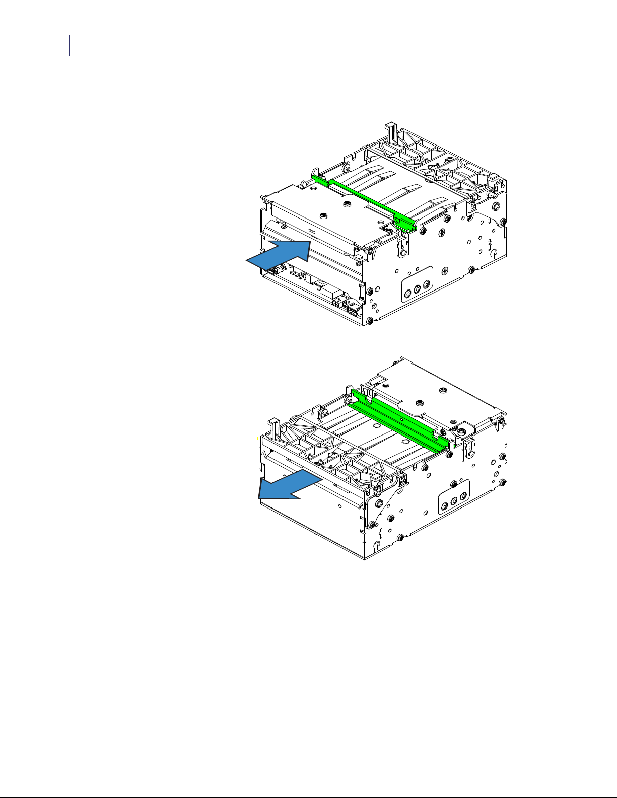
Opening the Printhead
When cleaning or servicing the printer, it is sometimes necessary to access the printhead.
1. Press the green printhead release bar to unlock the printhead.
2. Rotate the printhead assembly upward.
Printer Overview
Printer Features
11
Opening the Presenter
When cleaning or servicing the printer, it is sometimes necessary to access the presenter.
1. Squeeze the two presenter locking tabs together to unlock the presenter assembly.
2. Rotate the presenter assembly upward.
Figure 3-5 • Opening the Printhead
Figure 3-6 • Opening the Presenter
Note • When closing the presenter, make sure to close securely with an audible click on both
locking tabs.
6/22/2014 KR203 Hardware Integrator Guide P1028247-001 Rev. C

Printer Over view
12
Printer Information
Printer Information
Printer control Printer Control Panel - Allows very basic printer
configuration setup that includes a test page.
Print method Direct thermal page printing using thermal sensitive media.
Resolution 8 dots/mm (203 dpi)
Print speed 152 mm/s (6.0 inches/sec.) — Default
127 mm/sec.(5 inches/sec.)
101.6 mm/sec. (4 inches/sec.)
76.2 mm/sec. (3 inches/sec.)
Note: Printer media is rated for specific speed ranges and
some media types and materials will print better at slower
speeds.
Present speed 300 mm/s (11.81 inches/sec)
The KR203 Hardware Integrator uses the Looping Presenter
modes.
In pass-through presenter mode (loop size set to zero)
presenter speed matches the print speed.
Print duty cycle Up to 33%
Media Sensors Out of paper, paper in presenter, black mark, and an optional
external paper-low sensor.
Maximum print width 80 mm = 640 pixels
Auto Selected Print Widths
58 and 60 mm guide 60 mm = 480 pixels maximum
80 and 82.5 mm guide 80 mm = 640 pixels maximum
P1028247-001 Rev. C KR203 Hardware Integrator Guide 6/22/2014

Media Types
Printer Overview
Printer Mounting
13
Receipt Media Supply
Type
Outer Roll diameter 250 mm (9.84 inches) maximum
Spindle (core) diameter 25 mm minimum (typical core size)
Paper width 58, 60, 80, and 82.5 mm (common receipt roll widths)
Paper Thickness or Caliper 0.054 – 0.11 mm
Paper Density or
Grammage
Outside Wound Continuous Roll: Plain receipt, receipt with
black marks, and pre-printed receipt media with black marks.
Fanfold: Stacked receipt media with black marks and preprinted receipt media with black marks.
Note: The maximum roll diameter is dependent upon roll
holder in use and the kiosk design.
40 mm maximum
12 mm minimum with Small Core Media Roll Adapter
For information on ordering media, refer to Contacts
on page 2.
2
55 –110 g/m
Note - This is an approximate area density measurement that
varies by country, paper type and measurement method
applied.
(or gsm)
Printer Mounting
The printer can only be mounted to the kiosk using the four printer mounting screw holes
shown in the illustration below. The printer is most secure when using all four of the mounting
positions connecting the printer’s base to a rigid metal base plate in the kiosk. The kiosk’s
metal printer mounting plate should be connected to the kiosks electrical (earth) ground for
6/22/2014 KR203 Hardware Integrator Guide P1028247-001 Rev. C

Printer Over view
14
Printer Mounting
purposes of controlling static discharge and electrical noise.
1b
2
1a
Figure 3-7 • Printer Mounting
Table 3 • Mounting Configuration
Mounting Positions Kiosk’s Print Base Mounting Variation Details
1a and 1b Full coverage of printer’s
base plate
• Minimum mount positions.
• Supports the Quick-Fit Hubs
• Supported by most Zebra
accessory mounting solutions.
1a and 2 Partial (and Full) coverage
1 (a and b) and 2
of the printer’s base plate
• Minimum three point mounting
to fight torsional forces.
For information on ordering accessories, refer to Contacts on page 2.
P1028247-001 Rev. C KR203 Hardware Integrator Guide 6/22/2014

Printer Overview
Printer Mounting
15
X
Table4•M3Metric Mounting Screw Length
X 1.5mm minimum Printer mounting surface
Y 1.5mm Printer base plate thickness
Z 2mm maximum Penetration into circuit board area
X + Y = minimum length
X + Y + Z = maximum length
Mounting Orientations
The printer can be mounted horizontally or vertically depending on the design of the kiosk.
The maximum angle that the printer can operate from the nominal vertical or horizontal
orientations is dependent upon environmental conditions and the media in use.
M3 Screw
Figure 3-8 • Printer Mounting
Y
Z
Environmental conditions that may affect operation: Humidity, temperature, air circulation air
in the kiosk, and static buildup on adjacent kiosk components and surfaces, etc.
Media considerations:Receipt length, partial cut of receipt in receipt design, curl at the end of
the media roll, thickness and weight, perforations on fan-fold or receipt media, etc.
Other considerations: Media mounting, media path, media access, printer maintenance,
cabling, etc.
Note • In vertical mounting orientation the small core media adapter may be used to ensure
that media enters the present path.
The area of primary concern is the ‘loop area’ – this area requires special attention when
designing the kiosk. The printer requires space to store the printed receipt before presenting it
to the customer. The longer the receipt, the greater the area needed. When mounting the printer
at angles other than the nominal vertical or horizontal orientations, simulated receipt printing
operations should be observed with the chosen media for use in the kiosk and in the
environmental conditions that it will operate on-site.
6/22/2014 KR203 Hardware Integrator Guide P1028247-001 Rev. C

Printer Over view
16
Design Your Own Mounting
Design Your Own Mounting
The illustration below gives an example of a printer-mounting shelf:
Figure 3-9 • Printer Mounting
Additional space is required for paper loading and service access. Consider mounting the
printer on a movable platform so that the printer can be maintained outside the printer
enclosure.
Note • We recommend making the output slot 97 mm wide. This width should accommodate
all paper widths that the KR203 Hardware Integrator printers can handle.
Caution • NEVER use screws that go into the printer more than 4 mm! This will damage or
destroy the electronics inside. See Printer Mounting on page 13.
P1028247-001 Rev. C KR203 Hardware Integrator Guide 6/22/2014

Printing
Printer Overview
Printing
The printing sequence starts with the leading edge of the media resting at the cut position after
loading media or printing a previous receipt. The printer begins printing the page upon
completion of the transfer of the image to the printer. When the page has finished printing, the
printer cuts the receipt to finish.
The printer then presents the receipt to the kiosk client. When the client pulls the receipt, the
printer immediately detects the roller movement and causes the printer to accelerate the receipt
out of the printer. This helps prevent damage to the receipt.
17
Media Input - Use Auto or Manual
media loading procedure.
Loop area- stores receipt until printing
completed.
Media Cutter - Full or partial media
cuts.
Looping Presenter
The looping presenter mechanism has many benefits:
• It handles documents of various lengths by storing the printed paper in a loop.
• It holds the printout until fully printed and cut before presenting the completed printout to
the customer. This eliminates issues many other printers have when the kiosk client tries
to remove media before printing has finished.
• A portion of the printout is presented. When the customer takes the receipt, the printer
detects a movement and issues the rest of the receipt at 300 mm/s to help ensure receipt is
removed undamaged. The amount of media presented can be customized to account for
differences in the thickness of the kiosk wall.
Figure 3-10 • Printing Sequence
Table 5 • Printing Sequence
Printhead and Platen (Drive) Roller.
Media Drive Roller and Loop Stop
(forward only.)
Media Present - Detects a media pull
with motor.
6/22/2014 KR203 Hardware Integrator Guide P1028247-001 Rev. C

Printer Over view
18
Printing
Page Modes
The printer sets the following modes using the Windows driver.
Variable Page Mode The length of the page (receipt) varies with the contents. Pages
shorter than the minimum page (receipt) length will be extended
to the minimum length. Pages (receipts) longer than the
maximum page (receipt) length will print the maximum page
(receipt) length, then place the extra data on additional pages
(receipts).
Fixed Page Mode The length of the page (receipt) is fixed. The printer will always
create a page (receipt) of the defined length. If the page (receipt)
image is shorter than the defined length, blank media will be fed
until the defined length is reached. Any data beyond the defined
length will be placed on subsequent pages (receipts). Between
pages (receipts), the cut behavior (full or partial) specified for
the print job will occur.
Black Mark Mode Marks on the paper set the form length. Black mark mode can
work with either fixed or variable length pages (receipts). In
fixed page mode, the printer will force a cut at every black mark
and multiple pages can be imaged for one document. In variable
page mode, the printer will cut ar the next black mark after the
end of the data.
Printer Configuration Methods and Tools
The KR203 Hardware Integrator printer has a variety of printer configuration methods for the
software and hardware integrator. Each is designed to assist you with various kiosk design and
integration tasks. These integration tasks include printer startup, proof of concept, receipt
design, status reporting, multi-printer configuration, and kiosk application design. The
configuration methods from hardware to programming application include:
• Media Guides — Sets the printer’s maximum print width. See Media Guide
on page 18 and Installing the Media Guide on page 18.
• Control Panel — The printer’s control panel (Feed Button) provides access self test,
media guide detection, test prints, and resetting the printer to factory defaults. See the
Feed Button on page 19.
• Windows Drivers — Quickly allows the developer to use the printer, test
configuration options, send programming commands or files, and print directly from
Windows applications. Refer to the Software Integrator Guide (P1028248) for
additional information.
P1028247-001 Rev. C KR203 Hardware Integrator Guide 6/22/2014
 Loading...