

Page 1

Zebra® KR203
Kiosk Receipt Printer
Windows® CE
Software Integrator
P1028251-001 Rev. A
Guide
Page 2

© 2011 ZIH Corp. The copyrights in this manua l and th e so f tware and/or firm ware in the
printer described therein are owned by ZIH Corp. Unauthorized reproduction of this
manual or the software and/or firmware in the printer may result in imprisonment of up to
one year and fines of up to $10,000 (17 U.S.C.506). Copyright violators may be subject to
civil liability.
®
This product may contain ZPL
Equalizer
®
Circuit; E3®; and Monotype Imaging fonts. Software © ZIH Corp. All rights
, ZPL II®, and ZebraLink™ programs; Element Energy
reserved worldwide.
ZebraLink and all product names and numbers are trademarks, an d Zebra, the Zebra
logo, ZPL, ZPL II, Element Energy Equalizer Circuit, and E
3
Circuit are registered
trademarks of ZIH Corp. All rights reserved worldwide.
All other brand names, product names, or trademarks belong to their respective holders.
Proprietary Statement This man ual contains proprietary information of Zebra
Technologies Corporation and it s subsid iaries (“Zeb ra Technologies”). It is intended solely
for the information and use of parties operating and ma in taining the eq uipm en t de scr ibe d
herein. Such proprietary information may not be used, reproduced, or disclosed to any
other parties for any other purpose without the express, written pe rmission of Zebra
Technologies.
Product Improvements Continuous improvement of products is a policy of Zebra
Technologies. All specifications and designs are subject to change without notice.
Liability Disclaimer Zebra Technologies takes steps to ensure that its published
Engineering specifications and manuals are correct; however, errors do occur. Zebra
Technologies reserves the right to correct any such errors and disclaims liability resulting
therefrom.
Limitation of Liability In no event shall Zebra Technologies or anyone else involved in
the creation, production, or delivery of the accompanying produ ct (including hardwar e and
software) be liable for any damages whatsoever (including, without limitation,
consequential damages including loss of business profits, business interruption, or loss of
business information) arising out of the use of, the results of use of, or inability to use such
product, even if Zebra Technologies has been advised of the possibility of such damages.
Some jurisdictions do not allow the exclusion or limitation of incidental or conseque ntial
damages, so the above limitation or exclusion may not apply to you.
P1028251-001 Rev. A KR203 Windows CE Software Integrator Guide 3/1/2011
Page 3

Contents
Contents . . . . . . . . . . . . . . . . . . . . . . . . . . . . . . . . . . . . . . . . . . . . . . . . . . i
Introduction . . . . . . . . . . . . . . . . . . . . . . . . . . . . . . . . . . . . . . . . . . . . . . . 1
Who Should Use This Document. . . . . . . . . . . . . . . . . . . . . . . . . . . . . . . 1
How This Document Is Organized. . . . . . . . . . . . . . . . . . . . . . . . . . . . . . 1
Contacts. . . . . . . . . . . . . . . . . . . . . . . . . . . . . . . . . . . . . . . . . . . . . . . . . . 2
Document Conventions . . . . . . . . . . . . . . . . . . . . . . . . . . . . . . . . . . . . . . 3
Windows CE Driver . . . . . . . . . . . . . . . . . . . . . . . . . . . . . . . . . . . . . . . . . 5
Description. . . . . . . . . . . . . . . . . . . . . . . . . . . . . . . . . . . . . . . . . . . . . . . . 5
Windows CE Driver. . . . . . . . . . . . . . . . . . . . . . . . . . . . . . . . . . . . . . 5
Printer Driver. . . . . . . . . . . . . . . . . . . . . . . . . . . . . . . . . . . . . . . . . . . 6
Port Monitor. . . . . . . . . . . . . . . . . . . . . . . . . . . . . . . . . . . . . . . . . . . . 7
Print Spooling . . . . . . . . . . . . . . . . . . . . . . . . . . . . . . . . . . . . . . . . . . 7
Status Monitoring. . . . . . . . . . . . . . . . . . . . . . . . . . . . . . . . . . . . . . . . 7
GetPrinterStatus . . . . . . . . . . . . . . . . . . . . . . . . . . . . . . . . . . . . . . . . 8
Control Panel Extension . . . . . . . . . . . . . . . . . . . . . . . . . . . . . . . . . . 9
KR203CPL . . . . . . . . . . . . . . . . . . . . . . . . . . . . . . . . . . . . . . . . . . . . 9
Printer and Driver Parameter Setting and Maintenance . . . . . . . . . . 9
Installation . . . . . . . . . . . . . . . . . . . . . . . . . . . . . . . . . . . . . . . . . . . . . . . 10
Driver Installation. . . . . . . . . . . . . . . . . . . . . . . . . . . . . . . . . . . . . . . 10
Update Firmware. . . . . . . . . . . . . . . . . . . . . . . . . . . . . . . . . . . . . . . . . . 11
UI Option. . . . . . . . . . . . . . . . . . . . . . . . . . . . . . . . . . . . . . . . . . . . . 11
Command Line Option . . . . . . . . . . . . . . . . . . . . . . . . . . . . . . . . . . 11
Printer Settings . . . . . . . . . . . . . . . . . . . . . . . . . . . . . . . . . . . . . . . . . . . 12
Device Setting. . . . . . . . . . . . . . . . . . . . . . . . . . . . . . . . . . . . . . . . . 12
Media Width . . . . . . . . . . . . . . . . . . . . . . . . . . . . . . . . . . . . . . . 13
Media Height . . . . . . . . . . . . . . . . . . . . . . . . . . . . . . . . . . . . . . 13
Darkness . . . . . . . . . . . . . . . . . . . . . . . . . . . . . . . . . . . . . . . . . 14
Max Print Speed . . . . . . . . . . . . . . . . . . . . . . . . . . . . . . . . . . . 14
Media Tracking . . . . . . . . . . . . . . . . . . . . . . . . . . . . . . . . . . . . 14
Top Margin . . . . . . . . . . . . . . . . . . . . . . . . . . . . . . . . . . . . . . . . 15
8/6/2010 KR203 Software Integrator Guide P1028248-001 Rev. A
Page 4

ii
Contents
Bottom Margin . . . . . . . . . . . . . . . . . . . . . . . . . . . . . . . . . . . . . 15
Cutter Mode . . . . . . . . . . . . . . . . . . . . . . . . . . . . . . . . . . . . . . . 15
Partial Cut Width . . . . . . . . . . . . . . . . . . . . . . . . . . . . . . . . . . . 15
Presenter Loop Length . . . . . . . . . . . . . . . . . . . . . . . . . . . . . . 15
Eject Length . . . . . . . . . . . . . . . . . . . . . . . . . . . . . . . . . . . . . . . 15
Present Length Addition . . . . . . . . . . . . . . . . . . . . . . . . . . . . . 15
Presenter Timeout . . . . . . . . . . . . . . . . . . . . . . . . . . . . . . . . . . 15
Clear Presenter . . . . . . . . . . . . . . . . . . . . . . . . . . . . . . . . . . . . 15
Tools . . . . . . . . . . . . . . . . . . . . . . . . . . . . . . . . . . . . . . . . . . . . . . . . 16
About. . . . . . . . . . . . . . . . . . . . . . . . . . . . . . . . . . . . . . . . . . . . . . . . 17
Setting Black Mark Mode. . . . . . . . . . . . . . . . . . . . . . . . . . . . . . . . . . . . 18
Troubleshooting . . . . . . . . . . . . . . . . . . . . . . . . . . . . . . . . . . . . . . . . . . 19
Status Light Descriptions. . . . . . . . . . . . . . . . . . . . . . . . . . . . . . . . . . . . 19
Application LED States . . . . . . . . . . . . . . . . . . . . . . . . . . . . . . . . . . 19
Application User Interface. . . . . . . . . . . . . . . . . . . . . . . . . . . . . . . . 21
Print Quality Problems. . . . . . . . . . . . . . . . . . . . . . . . . . . . . . . . . . . . . . 21
Media Sensing Problems. . . . . . . . . . . . . . . . . . . . . . . . . . . . . . . . . . . . 23
Other Problems . . . . . . . . . . . . . . . . . . . . . . . . . . . . . . . . . . . . . . . . . . . 24
Resetting the Factory Default Values . . . . . . . . . . . . . . . . . . . . . . . . . . 26
Contact Technical Support. . . . . . . . . . . . . . . . . . . . . . . . . . . . . . . . . . . 26
Appendix A . . . . . . . . . . . . . . . . . . . . . . . . . . . . . . . . . . . . . . . . . . . . . . . 1
KR203 Status codes . . . . . . . . . . . . . . . . . . . . . . . . . . . . . . . . . . . . . . . . 1
Appendix B . . . . . . . . . . . . . . . . . . . . . . . . . . . . . . . . . . . . . . . . . . . . . . . 1
Programming Example . . . . . . . . . . . . . . . . . . . . . . . . . . . . . . . . . . . . . . 1
Background. . . . . . . . . . . . . . . . . . . . . . . . . . . . . . . . . . . . . . . . . . . . 1
Monitoring While Printing . . . . . . . . . . . . . . . . . . . . . . . . . . . . . . . . . 1
Monitoring While Idle. . . . . . . . . . . . . . . . . . . . . . . . . . . . . . . . . . . . . 2
P1028248-001 Rev. A KR203 Software Integrator Guide 8/6/2010
Page 5

Who Should Use This Document
This guide is intended for use by any person who need s to setup the KR203 printer for use
with a Windows CE device.
1
Introduction
How This Document Is Organized
The manual is set up as follows:
Introduction
Windows CE Driver Installation, updates, preferences, and properties.
Troubleshooting
Appendix A KR203 status codes.
Appendix B Programming samples
This manual will be updated from time to time as printer functions and features may be
added or amended. You will always find the latest edition on our web site (http://
www.zebra.com). If you require information for functions not found in this manual edition,
please contact Technical Support for your region or the Zebra partner the printer was
purchased from.
Contact information, document conventions.
Sta tu s light description, user interf ace, error handling,
and fixes to common printing problems.
3/1/2011 KR203 Windows CE Software Integrator Guide P1028251-001 Rev. A
Page 6

Introduction
2
Contacts
Contacts
Technical Support via the Internet is available 24 hours per day, 365 days per year.
Web Site: www.zebra.com
E-mail Back Technical Library:
• E-mail address: emb@zebra.com
• Subject line: Emaillist
Self Service Knowledge Base: www.zebra.com/knowledgebase
Online Case Registration: www.zebra.com/techrequest
Which Department
Do You Need?
Regional Headquarters
Technica l Sup port
For questions on the operation
of Zebra equipment and
software, please call your
distributor. For additional
assistance, contact us.
Please have your model and
serial numbers available.
Repair Service Department
For back-to-base service and
repair.
Techni cal Training
Department
For Zebra product training
courses.
Inquiry Department
For product literature and
distributor and dealer
information.
Customer Service
Department (US)
Internal Sales Department
(UK)
For printers, parts, media, and
ribbon, please call your
distributor or contact us.
Key:
T: Telephone
F: Facsimile
E: E-mail
The Americas
Zebra Technologies Inter national,
LLC
475 Half Day Road, Suite 500
Lincolnshire, IL 60069 USA
T: +1 847 634 6700
Toll-free +1 866 230 9494
F: +1 847 913 8766
T: +1 877 ASK ZEBRA (275 9327)
F: +1 847 913 2578
Hardware: ts1@zebra.com
Software: ts3@zebra.com
Kiosk Printers:
T: +1 866 322 5202
kiosksupport@zebra.com
T: +1 877 ASK ZEBRA (275 9327)
F: +1 847 821 1797
E: repair@zebra.com
To request a repair in the U.S.,
go to www.zebra.com/repair
T: +1 847 793 6868
T: +1 847 793 6864
F: +1 847 913 2578
E: ttamerica@zebra.com
T: +1 877 ASK ZEBRA (275 9327)
E: inquiry4@zebra.com
T: +1 877 ASK ZEBRA (275 9327)
E: clientcare@zebra.com
.
Europe, Africa,
Middle East, India
Zebra Technologies Europe Limited
Dukes Meadow
Millboard Road
Bourne End
Buckinghamshire, SL8 5XF
United Kingdom
T: +44 (0) 1628 556000
F: +44 (0) 1628 556001
T: +44 (0) 1628 556039
F: +44 (0) 1628 556003
E: Tseurope@zebra.com
T: +44 (0) 1772 693069
F: +44 (0) 1772 693046
New requests: ukrma@zebra.com
Status updates:
repairupdate@zebra.com
T: +44 (0) 1628 556000
F: +44 (0) 1628 556001
E: Eurtraining@zebra.com
T: +44 (0) 1628 556037
F: +44 (0) 1628 556005
E: mseurope@zebra.com
T: +44 (0) 1628 556032
F: +44 (0) 1628 556001
E: cseurope@zebra.com
Asia Pacific
Zebra Technologies Asia Pacific
Pte. Ltd.
120 Robinson Road
#06-01 Parakou Building
Singapore 068913
T: + 65 6858 0722
F: +65 6885 0838
T: +65 6858 0722
F: +65 6885 0838
E: China: tschina@zebra.com
All other areas:
tsasiapacific@zebra.com
T: +65 6858 0722
F: +65 6885 0838
E: China: tschina@zebra.com
All other areas:
tsasiapacific@zebra.com
T: + 65 6858 0722
F: +65 6885 0838
E: China: tschina@zebra.com
All other areas:
tsasiapacific@zebra.com
E: China:
GCmarketing@zebra.com
All other areas:
AP ACChannelmarketing@zebra.co
m
T: +65 6858 0722
F: +65 6885 0836
E: China: order-csr@zebra.com
All other areas:
csasiapacific@zebra.com
P1028251-001 Rev. A KR203 Windows CE Software Integrator Guide 3/1/2011
Page 7

Document Conventions
The following conventions are used in this document to convey certain information:
Alternate Color – Cross-references contain links to othe r sections in this guide. If you are
viewing this guide online, click the blue text to jump to its location.
Note • Indicates information that emphasizes or supplements important points of the main
text.
Introduction
Document Conventions
3
3/1/2011 KR203 Windows CE Software Integrator Guide P1028251-001 Rev. A
Page 8

Introduction
4
Document Conventions
P1028251-001 Rev. A KR203 Windows CE Software Integrator Guide 3/1/2011
Page 9

Description
APPLICATION
GDI
DISPLAY DRIVER
PRINTER DRIVER
PORT MONITOR
USB
PORT
PRINTER
Windows CE Driver
2
Windows CE Driver
The following description applies to CE 5.0 and CE 6.0.
The illustration shows the relationship between the various system components involved
in printing.
Figure 2-1 • System Flowchart
3/1/2011 KR203 Windows CE Software Integrator Guide P1028251-001 Rev. A
Page 10

Windows CE Driver
6
Description
Printer Driver
The printer driver for the KR203 is named KR203.DLL. The Windows CE graphics device
interface (GDI) and display driver perform most of the work involved in printing. At the
beginning of the printing process, GDI creates a device context with attributes that are
retrieved from the printer driver during a call to DrvEnablePDEV. The display driver, not
the printer driver, is used to render subsequent drawing commands that are issued from
the application into the device context. Theref ore, some drawing functions that are pre sent
in a printer driver, such as DrvS tro kePath, are ne ver ca lled because the printer d river only
renders the document internally.
The printer driver converts the bitmap dat a from a GDI bitmap format into the for mat that is
recognized by the printer. This can include such operations as color reduction to the color
space of the printer , dat a compression, and d ata conversion in to the format that is used by
the printer – a format sometimes known as a page-description la ngu age (PDL) . Then, th e
printer driver calls the port monitor to send the rendered image to the printer.
Only a small number of the graphics driver functions defined for printer drivers are
required in printer drivers for Windows CE. Printer drivers are required to implement only
those graphics driver functions that are necessary for gathering printe r m etrics, setting up
the printer, starting and ending print jobs, and preparing content for printing.
The following table shows the functions implemented in the driver:
T able 2-1 • Driver Functions
Function Description
DrvCopyBits Translates between device-managed raster surfa ces
and graphics device interface (GDI) standard format
bitmaps.
DrvDisablePDEV Used by MGDI to notify a driver that the specified
PDEV structure is no longer needed.
DrvDisableSurface Used by the GDI to notify a driver that the surface
created by the DrvEnableSurface function for the
current device is no longer needed.
DrvEnableDriver Specifies the initial driver entry point exported by the
driver DLL for devices that link directly to GWES, such
as display drivers and printer drivers. It fills a
DRVENABLEDATA structure with the driver version
number and calling addresses of functions supported
by the driver
DrvEnablePDEV Enables a device context for drawing and returns
device metrics for the target printer or display device in
a GDIINFO structure. Printer drivers call a display
driver's DrvEnablePDEV function to create and
initialize the device context, and then substitute the
printer's device metrics before returning the device
context to the GDI for bitmap rendering.
DrvEnableSurface Sets up a surface to be drawn on and associates it with
a specified PDEV.
DrvEndDoc Called by the GDI to finish or abort a print job.
P1028251-001 Rev. A KR203 Windows CE Software Integrator Guide 3/1/2011
Page 11

Windows CE Driver
Description
T able 2-1 • Driver Functions
Function Description
DrvGetModes Lists the modes supported by a specified device.
DrvStartDoc Called by the GDI to start a print job.
DrvStartPage Called by the GDI to start printing the next page of a
print job.
GetPrinterInfo Obt ains information about printers, such as the name
of the printer or whether the printer can print in color.
PrinterClose Closes a printer handle previously opened by a call to
the PrinterOpen function.
PrinterOpen Opens a specified printer port and return s a handle to
the printer.
PrinterSend Sends a block of data to a printer.
ReportPrinterS tatus Returns the st atus of a pr inter or printing operation that
is in progress.
GetPrinterSt atus Returns a specific KR203 status.
7
Note • The table includes links to descriptions of the driver functions.
Port Monitor
The port monitor for the KR203 is called KRPort.DLL. Printing is supported over universal
serial bus (USB) port only. The printing architecture provides application programming
interfaces (APIs) that are exposed by the Graphics, Windowing, and Events Subsystem
(GWES) to communicate with the printer driver. The printer driver communicates with the
port driver that sends the print data over the supported bus. Therefor e, the pr inter driver i s
independent of the bus and the corresponding bus driver.
Print Spooling
No separate printer spooler component exist s in Windows CE, unlike the desktop ver sions
of the Windows OS. With Windows CE, spooling or background printing is implemented in
the printer driver itself. However, because print spooling typically consumes a lot of
memory, limited memory might be a problem. A practical print spooler usually has to
implement a complicated compression scheme to store spooled documents before
printing.
Status Monitoring
In order to allow applications to get status from the printer, there are two functions
implemented: 1) the default ReportPrinterStatus function described in the MSDN
documentation, and; 2) a new function GetPrinterStatus that returns the actual printer
status (see Table 2-2, Printer Status Codes on page 8).
3/1/2011 KR203 Windows CE Software Integrator Guide P1028251-001 Rev. A
Page 12

Windows CE Driver
8
Description
GetPrinterStatus
This function gets the specific Printer status for the KR203.
Syntax DWORD WINAPI GetPrinterStatus(HANDLE hPrinter,
LPPRINTERSTATUS status)
Parm
hPrinter - HANDLE - Handle to the printer
status - LPPRINTERSTATUS - The status to be set.
Return DWORD - Returns
ERROR_SUCCESS if everything went Ok, else :
ERROR_UNKNOWN_PORT - If hPrinter is
INVALID_HANDLE_VALUE
ERROR_READ_FAULT - If read fail
ERROR_WRITE_FAULT - If write fail
ERROR_NOT_SUPPORTED - If hPrinter is not supported
The following table contains all status codes that can be reported by the KR203 printer
from the application.
T able 2-2 • Printer Status Codes
Number Name Type Group
0 Ok Normal Informational Solid green
1 Paper jam in presenter Normal Severe 1 red flash
2 Cutter Jam Normal Severe 2 red flashes
4 Print head lifted Normal Severe 4 red flashes
3 Out of paper Normal Severe 3 red flashes
5 Paper feed error Normal Severe 5 red flashes
6 Head temperature error Normal Severe auto-
clear
10 Black mark not found One-time Informational Not signaled
11 Black mark calibration
error
12 Index error One-time Informational Not signaled
16 Timeout Occurred One-time Informational Not signaled
18 Out of range One-time Informational Not signaled
One-time Informational Not signaled
LED
Reporting
Yellow
flashing
19 Paper low Normal Warning Not signaled
20 Media in presenter Normal Informational Not signaled
24 Invalid operation One-time Informational Not signaled
26 Target is read only One-time Informational Not signaled
40 Printer entered USB bus One-time Informational Not signaled
P1028251-001 Rev. A KR203 Windows CE Software Integrator Guide 3/1/2011
Page 13

T able 2-2 • Printer Status Codes
Windows CE Driver
Description
9
Number Name Type Group
41 System calibration error One-time Informational Not signaled
42 System calibration
success
One-time Informational Not signaled
Control Panel Extension
In order to open the control panel and double click the program icon, a control panel
extension is supplied with the driver.
KR203CPL
This component enables users to change settings for the printer and printer driver.
You can access the Control Panel through Start->Settings->Control Panel
Printer and Driver Parameter Setting and Maintenance
To provide an easy interface to set printer and driver parameters on the CE device, an
application is provided that handles device settings, and offers a Tools tab (see “Tools” on
page 17) to perform ce rtain main tena nce functions and print a printer configuration she e t.
LED
Reporting
The driver settings are done via the KR203 Settings application that can be found in the
Control Panel.
3/1/2011 KR203 Windows CE Software Integrator Guide P1028251-001 Rev. A
Page 14

Windows CE Driver
10
Installation
Installation
Driver Installation
The Zebra CE driver ZIP package includes the following files:
• Control Panel extension
• KR203CPL.CPL - This component enables users to change settings for the printer
and printer driver.
• KR203.DLL - The Printer Driver.
• KRPort.DLL - The Port Monitor.
• KRErr.DLL - The error handler.
• KR203.CPY - A sample copy file.
• KRDevice.EXE - The Parameter setup application.
• KRConfig.DLL - A helper DLL for the parameter setup applic ation.
• FWDownload.EXE - The firmware update application
Extract the Zebra CE driver files for the KR203 from the ZIP file and deploy the driver files
(KR203, KRPort, KRErr and KR203CPL) to the Windows directory. The sample copy file
(KR203.CPY) is included as a template for writing a copy file. This file is used during each
restart to copy files from permanent storage to their respective directories.
P1028251-001 Rev. A KR203 Windows CE Software Integrator Guide 3/1/2011
Page 15

Update Firmware
UI Option
Check the firmware version installed on the printer by printing a configuration label (see
“Tools” on page 17), the firmware version will be shown.
Go to the Zebra Website at www.zebra.com and follow the instructions to download the
latest version to your computer.
Copy the firmware package to the device to which the printer is connected and that runs
the driver. Select the port the target printer is connected to and then click “Select FW”.
Navigate to the firmware file and click “Download Firmware”. Confirm the installation by
clicking “Y es”. The status light on the printer will flash intermittently between green and red
indicating that a firmware update is in progress. The printer will reset when it has fini shed
the upload.
Command Line Option
Windows CE Driver
Update Firmware
11
The download application also offers a command line option to allow for remote
deployment of the firmware file and application and execution via a short cut link.
The following shows a sample command line:
\Application\Zebra\FWDownload.exe /P LPT1: /F
\Application\Zebra\K69_1_1.bin
Where /P is the port used to send data to the printer and /F is the firmware file including
directory location where the file is stored.
The following is a sample short cut link:
78#\Application\Zebra\FWDownload.exe /P LPT1: /F
\Application\Zebra\K69_1_1.bin
After the program has finished, a log file (KR203FWDownload.log) showing the actions
and results during the update process will be saved to the system root directory.
3/1/2011 KR203 Windows CE Software Integrator Guide P1028251-001 Rev. A
Page 16

Windows CE Driver
12
Printer Settings
Printer Settings
Device Setting
This dialog is used to control the Printer and driver settings:
Figure 2-2 • Device Settings Tab
P1028251-001 Rev. A KR203 Windows CE Software Integrator Guide 3/1/2011
Page 17

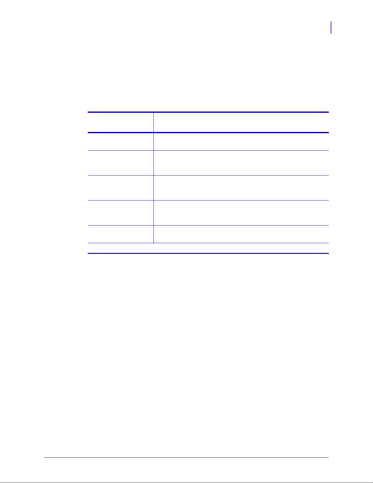
The following table describes the values and defaults of the parameters:
Table 2-3 • Parameter Settings and Defaults
Parameter Value Range Default Value
Media Width 58mm, 60mm, 80mm, 82mm 80mm
Media Height 100mm to 600mm 100mm
Darkness 0 to 30 20
Max Print Speed 75mm to 152mm 152mm
Media Tracking Continuous, Variable Length,
Mark Sensing
Top Margin 2mm to 12mm 12mm
Bottom Margin 0 to 9mm 0
Cutter Mode None, Every Page, End of
Document
Partial Cut Width 0, 10mm to 60mm 0
Presenter Loop Length 0 to 600mm 400mm
Eject Length 20mm to 600mm 50mm
Present Length Addition 0 to 255mm 0
Variable Length
Every Page
Windows CE Driver
Printer Settings
13
Presenter Timeout 0 to 300 seconds 0
Clear Presenter Disable, Enable Disable
The OK button will apply the parameter and exit the program.
The Cancel button will not apply the parameter and exit the program.
The Apply button will apply the parameter but not exit the program.
The Default button with set all parameters to factory default.
After the settings application has saved all the parameters these will be used during print
jobs.
The following settings will be sent to the printer during each print job:
Media Width
The media width can be set to 58 mm, 60 mm , 80 mm and 82.5 mm . The defa ult setting is
80 mm
Media Height
The media height can be set between the minimum page length of 100 mm and the
maximum page length of 600 mm. The default setting is 100 mm
3/1/2011 KR203 Windows CE Software Integrator Guide P1028251-001 Rev. A
Page 18
Windows CE Driver
14
Printer Settings
Darkness
The Darkness can be set between 0 and 30 with zero being the lightest. The default
setting is 20.
Figure 2-3 • Darkness set to 20 (default)
Max Print Speed
The max print speed can be set between 75 mm and 152 mm per second (mm/s). The
default setting is 152 mm/s. The actual print speed may vary depending on the darkness
and the content printed.
Media Tracking
Media Tracking sets Continuous, Variable Length, or Mark Sensing with the default set to
Variable Length. When media tracking is set to Continuous, the driver sends the full page
size to the printer (Page Mode), the page length will always be the same as the selected
paper size (e.g. if 58mm x 200mm Media is selected, the print will be 200mm long in Page
Mode). When media tracking is set to Variable Length, the driver will shorten the print to
the length of the page. The driver will end the print after the last printed element (text,
barcode, or graphic) then send a feed, cut, and eject command. The p age length may vary
from page to page but will always be a minimum of 92mm. When Mark Sensing is set, the
driver will send the page size to the printer, the printer will restrict the print to the area
between the black marks. If the printed area is larger than the space between the black
marks, it will print additional pages (receipts). The margin values in the receipt application
must be corrected after setting the driver values. If the margin in the application is set to
9mm and the driver is set to 2mm, the application setting will be enforced unless the driver
is changed accordingly.
Figure 2-4 • Darkness set to 0 (zero)
Compression sets whether the data is sen t to the printer co mpressed or unco mpressed. If
the data is sent uncompressed, this may result in longer print times.
P1028251-001 Rev. A KR203 Windows CE Software Integrator Guide 3/1/2011
Page 19
Top Margin
10 mm
Page 1
Page 2
Page 1
Page 2
Cut
Not Cut
60 mm
The Top Margin is the equivalent to the distance between the cutter and the print head and
is by default 12 mm. If it is set between the minimum of 2 mm or 11 mm it will reverse the
paper.
Bottom Margin
The Bottom margin can be set between 0 and 9 mm and will be added to the bottom of the
page in Variable Mode and will limit the printable area in Continuous Mode and Mark
Sensing. The default is 0.
Cutter Mode
Cutter Mode can be set to None, Every Page and Cut at the document end. Th e default is
Every Page. When set to Every Page and a multi-page document is printed each page will
be cut. If set to Cut at document end and a multi-page document is printed all pages will
print and only one cut at the end of the document will be issued. Partial Cut Width is used
with Cut at document end.
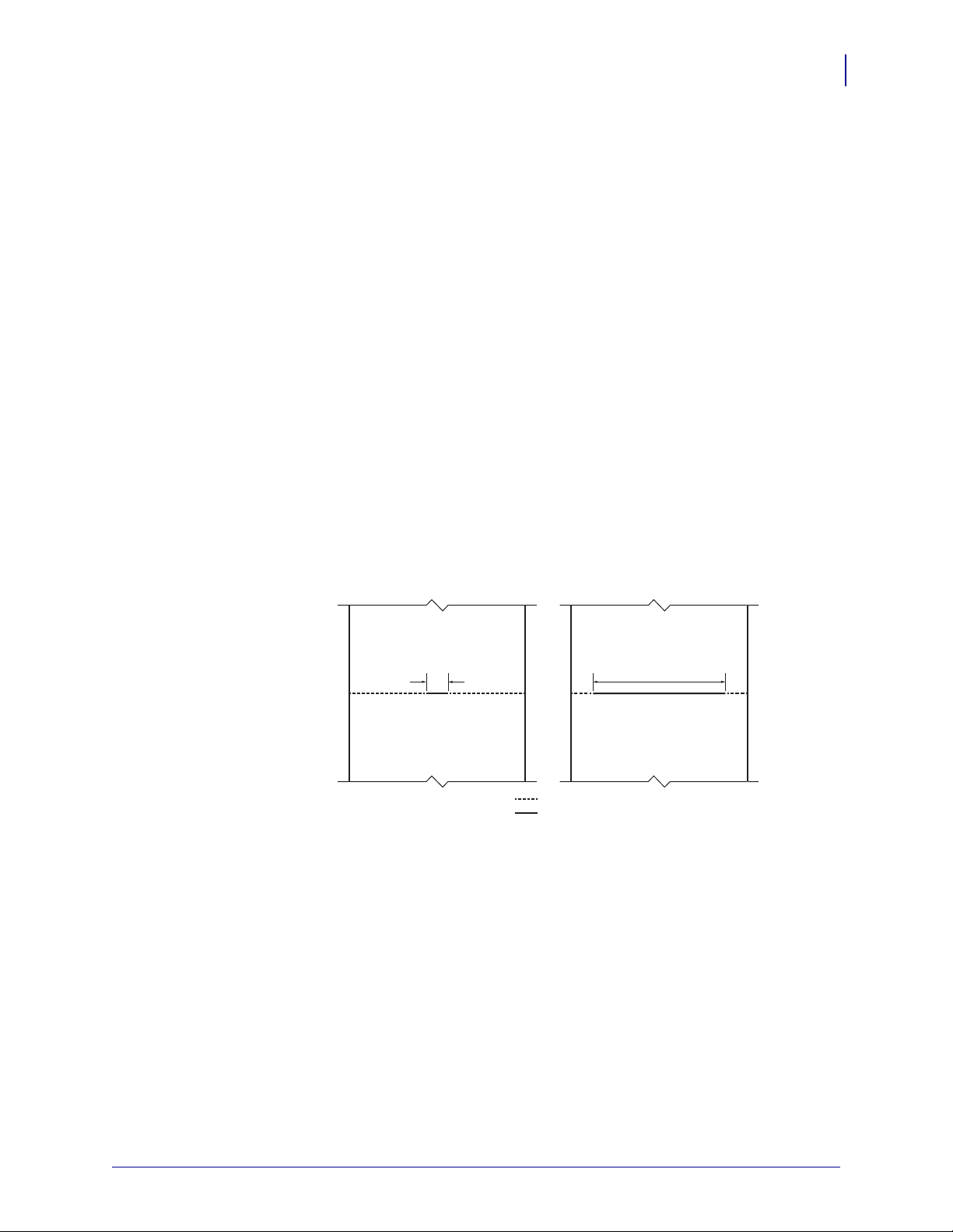
Partial Cut Width
Windows CE Driver
Printer Settings
15
Partial cut leaves multi-page receipts attached at the specified width. The p artial cut wid th
can be set to 0 and between 10 and 60 mm; the default is 0 and it disables partial cut (full
cut). Partial cut can only be used with the Cut at document endselection in Cutter Mode.
Presenter Loop Length
Presenter Loop Length determines how much paper is held in the presenter loop. The
presenter loop length can be set between 0 and 6 00 mm and the default val ue is 400 m m.
A setting of 0 disables the presenter loop and media feed directly through the presenter.
Figure 2-5 • Partial Cut Diagram
Eject Length
3/1/2011 KR203 Windows CE Software Integrator Guide P1028251-001 Rev. A
Eject Length determines how much paper is exposed for the customer. The range is from
20mm to 600mm with the default set to 50mm. If the eject length is set larger than the
length of the receipt, the printer will retain a portion of the receipt in the presenter unless
the “Clear Presenter” option is set to “Enable”.
Page 20

Windows CE Driver
16
Printer Settings
Present Length Addition
Presenter Length Addition is an additional length to compensate for the thickness of the
kiosk wall. The range is from 0 to 255mm with the default set to 0.
Presenter Timeout
Presenter Timeout determines how long the presenter will hold the receipt before ejecting
it. The range for the timeout is from 0 to 300 seconds with the default set at 0.
Clear Presenter
Clear Presenter determines if a receipt is retained, or if it is ejected from the presenter
after the timeout. Clear Presenter should not be used with Page Hold and will be set to
“Disable” if Page Hold is selected.
P1028251-001 Rev. A KR203 Windows CE Software Integrator Guide 3/1/2011
Page 21

Tools
The Tools tab enables printer maintenance functions.
Windows CE Driver
Printer Settings
17
Figure 2-6 • Tools Tab
Printer Port setting – Tells the driver which port the printer is connected to.
Clear Kiosk Presenter – Ejects any media in the presenter.
Send PRN File – Sends a saved PRN file to the printer.
Set Black Mark Mode – Sets the printer to use black mark media.
Set Continuous Mode – Set the printer to print continuous pages.
Feed One Receipt – Feeds a single blank receipt.
Print Config Label – Prints a page with the printer configuration information .
3/1/2011 KR203 Windows CE Software Integrator Guide P1028251-001 Rev. A
Page 22

Windows CE Driver
18
Printer Settings
About
The About Tab shows the current driver version.
Figure 2-7 • About Tab
P1028251-001 Rev. A KR203 Windows CE Software Integrator Guide 3/1/2011
Page 23

Setting Black Mark Mode
The printer is optimized to detect black marks printed with IR sensitive ink and ignore
preprint in IR blind ink. For information on black mark media requirements, refer to the
Hardware Integrator Guide (P1028247).
For 80 and 82.5mm media, the black marks will be centered 30mm to the right of the
paper center when viewing the imaged side of the receipt and print direction is downwa rd;
for 58 and 60mm media, the black marks will be centered 22mm to the left of the paper
when viewing the imaged side of the receipt and the print direction is downward.The
printer will support media with black mark thickn es s in printin g dir ec tio n of 2. 5 -9 .0 mm ,
and a width of 5.0 - 10.0mm when the black mark is centered on the sensor.
Refer to the Hardware Integrator Guide (P1028247) for black mark media requirements.
1. Choose the correct media guide for the desired media width. Refer to the Hardware
Integrator Guide (P1028247) for media guide installation instructions.
2. Perform a media guide calibration. Refer to "Application User Interface" on page 21.
Windows CE Driver
Setting Black Mark Mode
19
3. Load the desired media.
4. In the Tools tab of the Windows driver, click “Set Black Mark Mode”. A dialog box will
appear asking to confirm your selection, click “Yes”.
5. The printer will feed media, detect the black marks, and eject the media. Press the
Feed button on the printer several times to confirm the printer is cutting directly in the
center of the black marks.
6. In the device settings tab of the Windows driver, set the media tracking to “Mark
Sensing”. If you revert back to Continuous mode, set the media tracking back to
Continuous or Variable.
3/1/2011 KR203 Windows CE Software Integrator Guide P1028251-001 Rev. A
Page 24

Windows CE Driver
20
Setting Black Mark Mode
P1028251-001 Rev. A KR203 Windows CE Software Integrator Guide 3/1/2011
Page 25

Troubleshooting
Status Light Descriptions
Application LED States
3
Immediately after power is applied to the printer, a brief self test is performed and the
status light will report the following conditions:
Table 3-1 • Application LED States
Solid Green 0 - OK This code is reported when no other
codes are active. It indicates the
printer is functioning normally.
One Red Flash 1 - Paper Jam in
Presenter
Two Red Flashes 2 - Cutter Jam This code indicates that the printer
This code indicates that media is stuck
in the presenter . This error is set when
the printer attempts to eject the media
but cannot complete the operation.
This error is cleared by removing the
media from the presenter sensor.
could not find the cutter blade or could
not properly manage its position. The
error is set when the printer attempts
to cut but fails after three retries. This
error is cleared by cycling the power
off and on.
3/1/2011 KR203 Windows CE Software Integrator Guide P1028251-001 Rev. A
Page 26

Troubleshooting
20
Status Light Descriptions
Table 3-1 • Application LED States
Three Red Flashes 3 - Out of Paper This code indicates that the selected
EOP sensor has detected no media
present. This value is signaled wither
when the mark engine has detected a
mark larger than "TOF marker length”
plus 5mm, or when the A/D reading of
the EOP sensor drops below the “End
of paper threshold”. This error is
cleared after successful media load
(either via calibration of via regular
media load).
Four Red Flashes 4 - Print Head Lifted This code indicates that the print head
has been lifted. This error is cleared
by returning the print head to its
locked position.
Five Red Flashes 5 - Paper Feed Error This code indicates that the paper
failed to reach the presenter sensor
within the expected amount of time.
The error is signaled if the media does
not reach the presenter sensor after
feeding the length from the cuter to the
sensor plus 15mm. This error is
cleared by opening and closing the
print head, or by cycling power off and
on.
Y ellow Flashing 6 - Head Temperature
Error
This code indicates that the print head
has exceeded the maximum permitted
temperature. This status code is set
when the print head temperature
exceeds 65° C (149° F). When this
condition occurs, the printer feeds
100mm (4 inches) of blank media,
cuts, and presents. This error is
cleared automatically when the print
head temperature falls below 55° C
(131° F).
Rapid Amber
Flashing
Firmware missing or
corrupt
This code indicates that the bootware
has detected an incorrect or missing
checksum in the firmware. This error is
cleared when the firmware is reloaded
or updated. Refer to the Software
Integrator Guide for firmware upload
procedure.
P1028251-001 Rev. A KR203 Windows CE Software Integrator Guide 3/1/2011
Page 27
Application User Interface
With the printer power on, press and hold the feed button. Continue holding the feed
button until the status indicator flash sequence occurs. The next flash sequence occurs
after completion of the previous flash sequence. The flash sequences perform the
following functions:
Table 3-2 • Application User Interface
Troubleshooting
Print Quality Problems
21
Status Flash
Sequence
One Flash, then Solid
Green
Two Flash, then So lid
Green
Three Flash, then
Solid Green
Four Flash, then Solid
Green
Five Flash, then Solid
Green
If the feed button remains pressed after the fi ve flash sequence, the status light goes off.
Printer status is also reported during normal operation when an error occurs, or a status
request can be sent to the printer via the Windows driver. for error codes reported by the
Windows driver.
Appears for one second. This will print an internal self-test
page.
Appears for one second. Performs system calibration – must
be started with paper out of presenter and from under
printhead, and with no error signaled.
Appears for one second. Performs a simulated USB cable
connect and reconnect causing a USB plug-and-play event to
occur.
Appears for one second. Sets all printer settings to the default
with the exception of media guide calibration, then it will
perform the media guide calibration.
Appears for one second. Prints a 50% gray pattern, ejects it
and then prints a diagonal line pattern and ejects it.
Action
Print Quality Problems
No print on the label.
• The media may not be direct thermal media, or the thermal media coating is not facing
upward.
• Is the media loaded correctly? Is the thermal media coating facing upward?
• The printhead may be dirty or damaged.
• The printhead is dirty. Clean the printhead. Refer to the Service Manual
(P1028249) for instructions.
• The printhead is damaged. Replace the printhead. Refer to the Service Manual
(P1028249) for instructions.
• The printhead wiring may be damaged or not connected properly.
• Check the wiring connections at the printhead and the main logic board.
• Check for damage to the wiring. Replace the wiring if damaged.
3/1/2011 KR203 Windows CE Software Integrator Guide P1028251-001 Rev. A
Page 28

Troubleshooting
22
Print Quality Problems
The printed image does not look right.
• The printhead is dirty. Clean the printhead. Refer to the Service Manual (P1028249)
for instructions.
• The printhead has worn out. The printhead is a consumable item and will wear out
due to friction between the media and printhead. Using unapproved media may
shorten life or damage your printhead. Replace the printhead. Refer to the Service
Manual (P1028249) for instructions.
• Adjust the print darkness and/or print speed. See "Device Setting" on page 12.
• The Windows printer driver or application software may change these settings
and may require a change to optimize print quality.
• The media being used is incompatible with the printer. Be sure to use the
recommended media for your application, and always use Zebra-approved media.
• The platen (driver) roller maybe losing traction due to:
• Foreign objects attached to its surface.
• The rubbery smooth surface has become polished and slippery.
• The platen may need cleaning or replacement. Refer to the Service Manual
(P1028249) for instructions.
There are long tracks of missing print (blank vertical lines) on
several labels.
• The printhead may be dirty or damaged.
• The printhead is dirty. Clean the printhead. Refer to the Service Manual
(P1028249) for instructions.
• The printhead is damaged. Replace the printhead. Refer to the Service Manual
(P1028249) for instructions.
• The printhead has worn out. The printhead is a consumable item and will wear out
due to friction between the media and printhead. Using unapproved media may
shorten life or damage your printhead. Replace the printhead. Refer to the Service
Manual (P1028249) for instructions.
The printing does not start at the top of the receipt or misprinting of
one to three receipts.
• The printer needs to be calibrated (refer to the two-flash sequence of "Application
User Interface" on page 21).
• Reload the media. Refer to the Hardware Integrator Guide (P1028247) for
instructions.
P1028251-001 Rev. A KR203 Windows CE Software Integrator Guide 3/1/2011
Page 29

Media Sensing Problems
The KR203 printer default media mode is Continuous. The printer will remain in this mode
until it is changed by the Windows Driver.
The KR203 printer has automatic media calibration capability for black mark media. Once
the printer is printing or feeding media, the printer continually checks and adjusts the
media sensing to accommodate for minor changes in media p arameters from page to
page on a roll, and from roll to roll of media. The printer will automatically initiate a media
length calibration if the expected media length or the page to page gap distance has
exceeded the acceptable variation range when starting a print job or feeding media.
If the printer does not detect blacklines (or notches with black mark sensing) after feeding
the media the default maximum label length distance of 24 inches (610mm), then the
printer will report a media error.
Optionally, the printer can be set to do a short media calibration after loading media or
when closing the printhead with power on. The printer will then feed up to three labels
while calibrating.
Troubleshooting
Media Sensing Problems
23
The printer will not load the media.
• The media has changed, or a different media guide has been installed.
• Make sure the appropriate media guide is installed for the media being used.
Refer to the Hardware Integrator Guide (P1028247) for instructions.
• Perform the two-flash procedure to recalibrate the printer and then perform the
four-flash procedure to reset the printer default settings. Re fer to "Application LED
States" on page 19. Reload the media (refer to the Hardware Integrator Guide
(P1028247) for media loading procedures).
• Load the media manually. Refer to the Hardware Integrator Guid e (P1028247 ) for
instructions.
• The platen (driver) roller maybe losing traction due to:
• Foreign objects attached to its surface.
• The rubbery smooth surface has become polished and slippery.
• The platen may need cleaning or replacement. Refer to the Service Manual
(P1028249) for instructions.
• The media sensor may be dirty or damaged. Refer to th e Service Manual (P10 28249)
for instructions.
• The printhead assembly is not closed.
• Check the status light on either side of the printer . If the status light is showing four
red flashes then the printhead is not closed. Push down on the printhead
assembly until it locks into place.
3/1/2011 KR203 Windows CE Software Integrator Guide P1028251-001 Rev. A
Page 30

Troubleshooting
24
Other Problems
The printer will not eject the media.
• There is a jam under the printhead. Refer to the Service Manual (P1028249) fo r
instructions.
• The large media roll may be over torquing the feed motor. Install the large media roll
adapter. Refer to the Hardware Integrator Guide (P1028247) for instructions.
• The presenter rollers are dirty or damaged.
• The presenter rollers are dirty. Refer to the Service Manual (P1028249) for
instructions.
• The presenter rollers are damaged. Refer to the Service Manual (P1028249) for
instructions.
• There is a jam under the presenter. Refer to the Service Manual (P1028249) for
instructions.
• The presenter sensor may be dirty or damaged.
• The presenter sensor is dirty. Refer to the Service Manual (P1028249) for
instructions.
• The presenter sensor is damaged. Refer to the Service Manual (P1028249) for
instructions.
• The presenter has not cleared the previous receipt.
• Check the status light on either side of the printer. If the status light is showing one
red flash then the printer is reporting media in the presenter. Remove any media
that may be in the presenter.
• The presenter motor may need to be replaced. Refer to the Service Manual
(P1028249) for instructions.
• The presenter drive gears may be damaged or worn. Refer to the Service Manua l
(P1028249) for instructions.
Other Problems
The receipts are not cutting properly.
• The cutter blade may be worn. Replace the cutter blades. Refer to the Service Manual
(P1028249) for instructions.
• The cutter tensioner may be worn or damaged. Replace the cover plate assembly.
Refer to the Service Manual (P1028249) for instructions.
• Check the Cutter Mode setting, and the Partial Cut Width setting in the Windows
driver.See"Device Setting" on page 12.
P1028251-001 Rev. A KR203 Windows CE Software Integrator Guide 3/1/2011
Page 31

• The cutter motor may need to be replaced. Refer to the Service Manual (P1028249)
for instructions.
• The cutter drive gear, drive pin, or cutter actuator may be damaged or worn. Refer to
the Service Manual (P1028249) for instructions.
• Check for the latest firmware and driver version.
There are no lights on the printer.
• Make sure there is power applied to the printer.
• The control panel may be dirty or damaged. Refer to the Service Manua l (P1028249)
for instructions.
• The main logic board may be damaged. Refer to the Service Manual (P1028249) for
instructions.
• Check for the latest firmware and driver version.
Troubleshooting
Other Problems
25
A receipt format was sent to, but not recognized by, the printer.
• If the status LED is on or flashing, refer to "Application LED States" on page 19.
• Make sure the USB cable is correctly installed. Refer to the Hardware Integrator
Guide (P1028247) for instructions.
• A communications problem has occurred. Perform a USB detect (refer to the threeflash sequence of "Application User Interface" on page 21).
The receipts are not cutting at the black mark.
• Make sure you are using the appropriate media guide for the desired media width.
Refer to the Hardware Integrator Guide (P1028247) for media guide installation
instructions.
• Perform a media guide calibration. Refer to the two-flash sequence of "Application
User Interface" on page 21.
• Make sure you are using the appropriate media. Refer to the Hardware Integrator
Guide (P1028247) for black mark media requirements.
• Use the Windows driver to set the printer to black mark mode. See "Setting Black
Mark Mode" on page 19.
• Reload the media. Refer to the Hardware Integrator Guide (P1028247) for
instructions.
3/1/2011 KR203 Windows CE Software Integrator Guide P1028251-001 Rev. A
Page 32

Troubleshooting
26
Resetting the Factory Default Values
Resetting the Factory Default Values
Sometimes, resetting the printer to the factory defaults may solve some problems. Refer
to the four-flash sequence of "Application User Interface" on page 21.
Contact Technical Support
Technical Support via the Internet is available 24 hours per day, 365 days per year.
www.zebra.com
For questions on the operation of Zebra equipment and software, please call your
distributor. For additional assistance, contact us.
Please have your model and serial numbers available.
P1028251-001 Rev. A KR203 Windows CE Software Integrator Guide 3/1/2011
Page 33

Appendix A
KR203 Status codes
Table A-1 • Status Codes
Number Name Type Group LED
Reporting
0 Ok Normal Informational Solid green
1 Paper jam in presenter Normal Severe 1 red flash
2 Cutter Jam Normal Severe 2 red flashes
4 Print head lifted Normal Severe 4 red flashes
3 Out of paper Normal Severe 3 red flashes
5 Paper feed error Normal Severe 5 red flashes
6 Head temperature error Normal Severe auto-
clear
10 Black mark not found One-time Informational Not signaled
11 Black mark calibration error One-time Informational Not signaled
12 Index error One-time Informational Not signaled
16 Timeout Occurred One-time Informational Not signaled
18 Out of range One-time Informational Not signaled
19 Paper low Normal Warning Not signaled
20 Media in presenter Normal Informational Not signaled
24 Invalid operation One-time Informational Not signaled
26 Target is read only One-time Informational Not signaled
40 Printer entered USB bus One-time Informational Not signaled
41 System calibration error One-time Informational Not signaled
Yellow
flashing
42 System calibration success One-time Informational Not signaled
3/1/2011 KR203 Windows CE Software Integrator Guide P1028251-001 Rev. A
Page 34

A-2
Appendix A
KR203 Status codes
P1028251-001 Rev. A KR203 Windows CE Software Integrator Guide 3/1/2011
Page 35

Programming Example
Background
In order to incorporate the way status monitoring works for the KR203 printer setup, it is
important to understand what happ ens in a kiosk when you print, and when status
monitoring should take place.
Status monitoring can be handled in two ways:
Appendix B
• Monitoring in the printing application.
• Monitoring in a separate application.
When monitoring takes place in the printing application, normally the printer is observed
before sending a print job to see if the printer is "OK" and then send the print job . After the
print job is signaled as being printed, the status is checked again to see if the printer has
any errors or if the paper has been taken, etc.
Monitoring in a separate application usually doesn't allow direct interaction with the printed
job so the printer is polled as often as possible to get most accurate information on what
the printer is doing. This is usually very time consuming and care must be taken to achieve
synchronization and control over the current print job.
Monitoring While Printing
Status monitoring has been implemented in the internal printing structure of the driver.
When a document is opened, printed, and closed, the driver will check the printer status
before and after printing and will also react to write errors if any occur. It will then set the
printer status and raise the error event.
3/1/2011 KR203 Windows CE Software Integrator Guide P1028251-001 Rev. A
Page 36

B-2
Appendix B
Programming Example
Monitoring While Idle
In order to get status any time a status thread has to be implemented which reads printer
status and provides changed status informatio n in the same manner. The following code
snippet in C# may be used as a guide to develop such an application. The code is using
the KRConfig DLL.
KRConfig config = new KRConfig();
config.Load();//Load settings from registry
string msg = "";
try
{
config.open("LPT1:");
//getStatus is not synchronized with other read/write
functions
byte status = config.getStatus();
msg = "Status : " + status;
config.close("LPT1:");
}
catch (Exception ex)
{
msg = ex.Message;
MessageBox.Show("Status : " + msg);
P1028251-001 Rev. A KR203 Windows CE Software Integrator Guide 3/1/2011
 Loading...