

Page 1

Core i7
Core 2 Quad
Core 2 Duo
Core 2 Extreme
Pentium Dual-Core
Pentium D
Pentium 4
Celeron D
AMD Socket AM2+/AM2/754/939/940 CPU
Athlon 64
Athlon 64 X2 Dual-Core
Athlon X2 Dual-Core
Athlon 64 FX
Opteron
Dual-Core Opteron
Phenom
Sempron
※Please read this manual thoroughly prior to installation
http://www.zalman.com
User’s
Manual
CNPS9900 LED
Intel Socket 1366/Socket 775 CPU
Page 2

1) Common Components
① Cooler(CNPS9900 LED)
④ Four (4) Socket 775
Clip Support Fixing
Bolts (Silver)
⑤ One (1) Clip Support (top)
One (1) Backplate (bottom)
for Socket 775
⑥ One (1) Socket 775 Clip
② Thermal Grease
(ZM-STG1)
③ User’s Manual
2) Socket 775 (Intel) Components
1
1. Precautions
2. Components
Disclaimer) Zalman Tech Co., Ltd. is not responsible for any damages due to external causes,
including but not limited to, improper use, problems with electrical power, accident,
neglect, alteration, repair, improper installation, or improper testing.
1) Use and keep product away from reach of children and pets.
2) Do not ingest the Thermal Grease, and avoid its contact with skin and eyes. If contact
is made with skin, wash off with water. If ingested or irritation persists, seek medical
attention.
3) To prevent possible injuries, gloves must be worn while handling this product.
4) Excessive force exerted on the fan may cause damage to the fan and/or system.
5) Avoid inserting objects into the fan while it is in operation.
6) Check the components list and condition of the product before installation. If any
problem is found, contact the retailer to obtain a replacement.
7) Zalman is not responsible for any damages caused by overclocking.
8) During transportation of the system, the cooler must be removed. Zalman is not
responsible for any damages that occur during the transport of a system.
9) Product design and specifications may be revised to improve quality and performance.
Page 3

1) Installation Requirements
①
Space Requirements
The cooler’s installation requires unobstructed space with dimensions of 142
mm(width),
96
mm(length), 165mm(height) and the CPU as a central reference point. Please
check if components such as ODD and PSU protrude into the required space.
②
Air Guide Removal
Air guides on enclosures must be removed, before the cooler’s installation, for
they protrude into the cooler’s required space.
3. Installation
96mm
165mm
Air Guide
142mm
⑦ One (1) AMD Clip ⑧ One (1) AMD Clip Lever
3) Socket AM2+/AM2/754/939/940 (AMD) Components
2
⑦ Four (4) Socket 1366 Clip
Support Fixing Bolts (Gold)
⑧ Four (4) Socket 1366 Washers
⑨ One (1) Socket 1366
Clip Support
3) Socket 1366 (Intel) Components
⑩ One (1) Socket 1366 Clip
Page 4

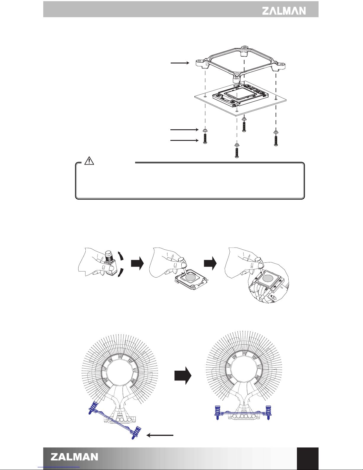
③
Plastic Band Removal
Please remove this plastic band before installing the cooler.
The band’s purpose is to protect the cooler during transport.
3
During installation or removal, please take precautions to avoid excessive
impact on the cooler.
Please hold the cooler
with both hands as
shown in the diagram.
Warning
CAUTION
Page 5

2) Installation on Intel Socket 775 / 1366
①- ⒶSocket 775 Clip Support and Backplate Installation
Align the Socket 775 Clip Support (top) and Backplate (bottom) with the motherboard
installation holes and secure with Socket 775 Clip Support Fixing Bolts (Silver).
Socket 775 Clip Support
Fixing Bolt (Silver)
Socket 775 Clip Support (top)
Motherboard
Socket 775 Backplate (bottom)
④
Cooler Orientation
In relation to the cooler’s centrally located fan, air flows from the “thinner”(front)
heatsink to the “thicker”(rear) heatsink. As shown in the diagram below, it is
recommended that the cooler be installed so that air flows from the cooler toward
the enclosure’s rear exhaust fan to be released.
4
Rear Side
Front Side
Enclosure’s (Rear) Exhaust
PSU
Socket 775 Clip Support Fixing Bolts (Silver) must be used.
VGA Slot
Warning
Page 6
②
Thermal Grease Application
Clear off any particles or residue from the CPU’s surface then spread (outwards
from center) a thin but thorough layer of Thermal Grease on the CPU and the base
of the cooler.
5
①- ⒷSocket 1366 Clip Support Installation
Socket 1366 Clip Support
Socket 1366 Washer
Socket 1366 Clip Support
Fixing Bolt (Gold)
Socket 1366 Clip Support Fixing Bolts(Gold) must be used. Installation using
the Socket 775 Clip Support Fixing Bolts(Silver) can cause damage to the
Socket 1366 Clip Support.
Motherboard
Warning
③
Clip Installation
First insert the Socket 775 / Socket 1366 Clip at a slanted angle and center the Clip
on top of the cooler’s Base Cover.
Socket 775 Clip / Socket 1366 Clip
Page 7

④
Cooler Installation
Align the center of the cooler with the
center of the CPU, and fix by tightening
the bolts on the Clip onto the Clip
Support.
The Clip must be installed lying flat, without leaning at a slant in any direction.
The PWM fan’s operation will vary depending on the motherboard’s BIOS
settings. After installation, the PWM Control Mode must be activated in the BIOS.
For details regarding PWM Control Mode, please refer to the motherboard’s manual.
⑤
Power Connection
Please connect the cooler’s 4-pin connector to the motherboard’s CPU Fan header.
For easier installation, stabilize the
Clip by initially tightening each bolt
by one turn or just enough to latch
onto the Clip Support’s threading.
6
Motherboard
CPU(PWM) Fan header
Page 8
3) Installation on AMD Socket AM2+/AM2/754/939/940
①
Thermal Grease Application
Clear off any particles or residue from the CPU’s surface then spread (outwards
from center) a thin but thorough layer of Thermal Grease on the CPU and the
base of the cooler.
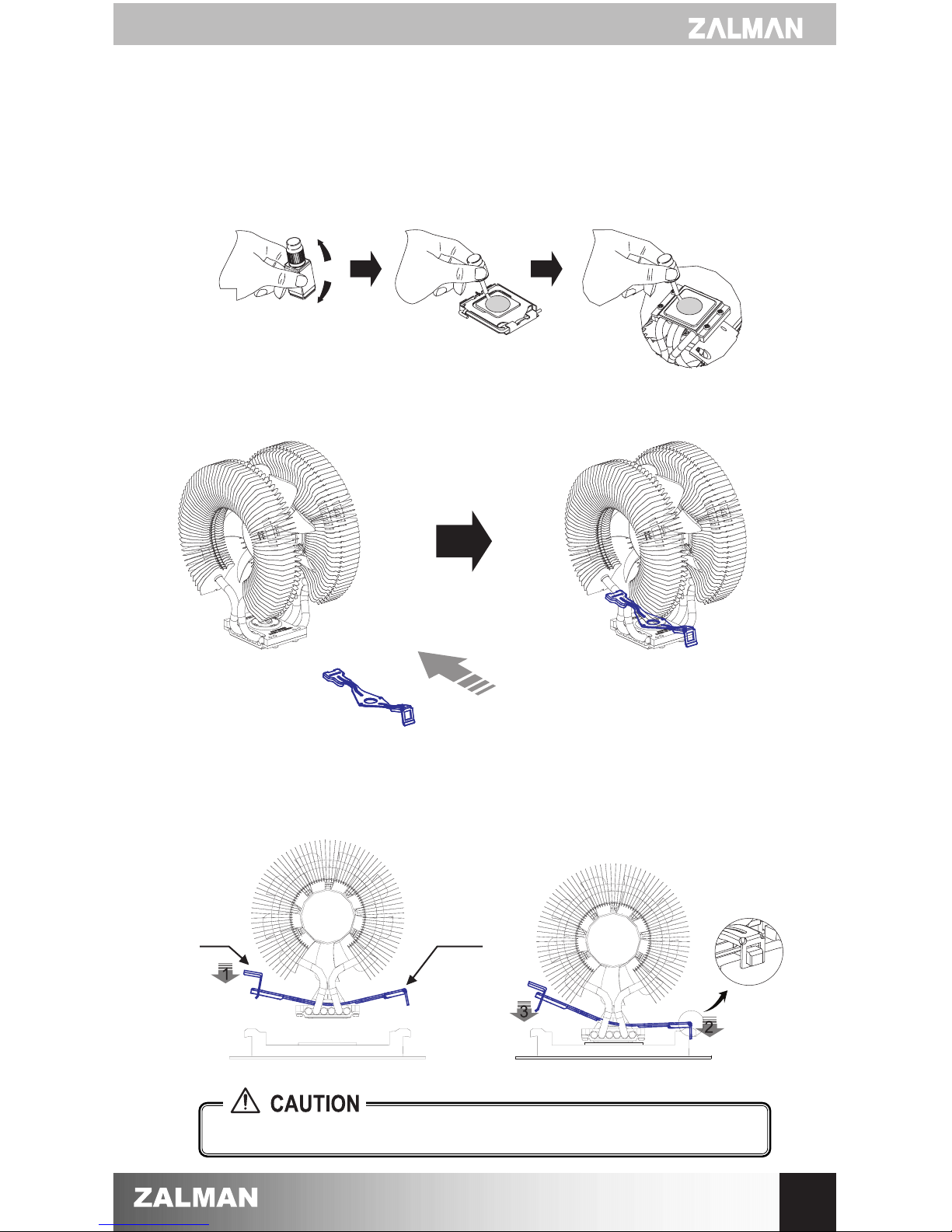
②
Clip Installation
Install the AMD Clip onto the cooler as shown in the diagram below.
③
Cooler Installation
Insert the Clip Lever into the Groove Side of the AMD Clip. Align and connect the
Clip’s Lug Slot with the Lug of the motherboard’s Retention Frame. Press onto the
Clip Lever when aligning the Lever’s Lug Slot with the Lug.
Once installed the Clip must not be leaning to one side.
7
Clip
Lever
AMD
Clip
Page 9

④
Power Connection
Please connect the cooler’s 4-pin connector to the motherboard’s CPU Fan
header.
The PWM fan’s operation will vary depending on the motherboard’s BIOS settings.
After installation, the PWM Control Mode must be activated in the BIOS.
For details regarding PWM Control Mode, please refer to the motherboard’s manual.
8
Motherboard
CPU(PWM) Fan header
 Loading...