

Page 1
ba76071e01 02/2012
ADA-WA 1
ADA-WA 4
Installation instructions
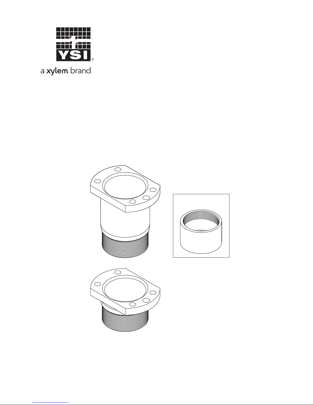
ADA-WA1ADA-WA1
ADA-WA4ADA-WA4
Fixing ring
for SensoLyt
Sensor adapter for installation in the
retractable armatures WA700/2 and WA 700/10
Page 2
ADA-WA 1; ADA-WA 4
2
ba76071e01 02/2012
Important information for using this adapter
together with a SensoLyt armature:
Observe the following note when you want to use a
SensoLyt measuring armature with the aid of the adapter:
Warning
For safety reasons, use only electrodes especially
specified for high pressure and temperature loads (for
example pH combination electrode SensoLyt SEA-HP,
order no. 109 118). For more information, refer to the
YSI catalog or the Internet. YSI assumes no liability for
damages caused by using different electrodes.
Page 3
ADA-WA 1; ADA-WA 4 Installation recommendations
3
ba76071e01 02/2012
Installation recommendations
General installation recommendations
Basic types of
installation
The optimum installation location must be individually determined for the type of sensor and the application.
Influential factors
The table on the following pages contains recommendations
and the special characteristics of the individual sensors.
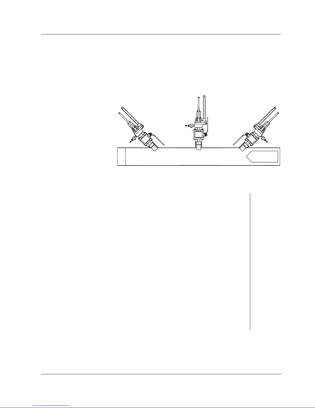
Flow
direction
Minimum distance: 80 mm
A
45 ° 45 °
BC
Good
Sufficient flow of the
sensor element
A, B
Burdening of the measuring medium with
long fibers - avoidance of them getting
caught on the sensor (rake effect)
C
Burdening of the sample with small stones
and abrasive particles - avoidance of any
damage to the sensor element
C
Avoidance of malfunctions of the optical
measurement (turbidity/total suspended solids) by captured air bubbles and particles
A, B
Avoidance of malfunctions of the optical
measurement (turbidity/total suspended solids) by wall surfaces
A, C
Page 4

Installation recommendations ADA-WA 1; ADA-WA 4
4
ba76071e01 02/2012
Overview of the recommended installation locations
Note
Always follow the I
NSTALLATION chapter of the respective sensor operating manual.
Sensor type Installation
location
(see
diagram on
page 3)
Advantages (+) /
Disadvantages (-)
Conclusion / Comments
TriOxmatic 700 IQ,
TriOxmatic 701 IQ,
TriOxmatic 702 IQ
FDO 700 IQ
B + Good flow
+ Low susceptibility to contamina-
tion
+ Low risk of membrane damage
TetraCon 700 IQ B + Good flow
+ Low susceptibility to contamina-
tion
Check and adjust cell constants
after installation (see sensor operating manual)
SensoLyt 700 IQ C + Good flow
+ Low susceptibility to contamina-
tion
- Danger of small stones damaging
the electrode
The enclosed fixing ring instead
of the protective hood improves
the incident flow.
Attention
: It is no protection
against small stones!
The best incident flow is
achieved when the diaphragm
points against the flow direction.
TFK 700 IQ C + Good flow
+ Low susceptibility to contamina-
tion
The enclosed fixing ring instead
of the protective hood improves
the incident flow.
Page 5

ADA-WA 1; ADA-WA 4
5
ba76071e01 02/2012
Overview of the recommended installation locations (continued)
Sensor type Installation
location
(see diagram
on page 3)
Advantages (+) /
Disadvantages (-)
Conclusion / Comments
VisoTurb 700 IQ,
ViSolid 700 IQ
Note
:
Please note the
special installation
recommendations
in the following
section.
A + Optimum flow of the sapphire disc
so there is no capture of air bubbles or large particles in front of
the sensor
- Susceptible to fibers getting
caught
- Risk of damage from stones and
abrasive particles
Optimum installation location
for measuring media without
contamination from fibers,
stones, or abrasive particles.
C + No risk of contamination by long fi-
bers
+ Low risk of damage from stones
and abrasive particles
- Susceptible to the capture of air
bubbles or large particles in front
of the sapphire disc (turbulence
effect)
In the case of contamination by
fibers, less prone to contamination than A.
B + Good flow of the sapphire disc, so
there is no interference from air
bubbles or large particles in front
of the sensor
- Risk of light reflections in narrow
containers
Good possibility in sufficiently
large containers or high values
of turbidity/total suspended solids.
Page 6

Installation recommendations ADA-WA 1; ADA-WA 4
6
ba76071e01 02/2012
Special installation recommendations:
VisoTurb 700 IQ and ViSolid 700 IQ
Note
Please also observe the general basic information in the
I
NSTALLATION chapter of the sensor operating manual. There
you will find important notes on optimizing the installation.
45 ° pipe installation
Pipe diameter at the installation location of at least DN 80.
The pipe should be straight and not tapered for a length
of at least 50 cm (VisoTurb 700 IQ) or 25 cm
(ViSolid 700 IQ) in the direction of observation. Angled or
tapered pipes can cause interference effects in the case
of low turbidity.
The front part of the sensor is pitched towards the flow.
Exception:
If there are high quantities of foreign bodies with fibrous
or large surfaces, as for example hairs, strings or leaves,
it may be of advantage to incline the sensor in the
direction of the flow so that the sapphire disc does not
face the flow.
Min. 80 mm
ESS/WA...
WA 700/...
Marking aid in
this direction
Flow
direction
ADA-WA1
straight pipe
VisoTurb: min. 50 cm
ViSolid: min. 25 cm
Page 7

ADA-WA 1; ADA-WA 4 Installation recommendations
7
ba76071e01 02/2012
The marking on the sensor shaft points towards the
pipeline. On page 9 you will find a description of how to
correctly align the sensor with the aid of a marking aid on
the sensor plug head connector.
90 ° pipe installation
Note
The 90 ° pipe installation is only suitable for large pipe
diameters and high turbidity/total suspended solids values
respectively. For other cases, the 45 °installation should be
preferred.
For installation, select a location with a pipe diameter as
big as possible.
Rotate the sensor so that the marking on the shaft (arrow
symbol) points in the direction of the pipe axis. On page 9
you will find a description of how to correctly align the
sensor with the aid of a marking aid on the sensor plug
head connector.
ESS/WA...
WA 700/...
Marking aid in
this direction
Large ballcock
turned
ADA-WA1
Page 8

Installation recommendations ADA-WA 1; ADA-WA 4
8
ba76071e01 02/2012
Other containers
Installation angle 90 °
The distance between the mounting opening and the wall
opposite should be as great as possible.
The area in front of the measuring windows (hatched area
in the drawing) has to be free of interfering surfaces.
10 cm
ESS/WA...
WA 700/...
Large ballcock
turned
ADA-WA1
No interfering surfaces
in this area!
Page 9

ADA-WA 1; ADA-WA 4 Installation
9
ba76071e01 02/2012
Installation
Note
Please also observe the I
NSTALLATION chapter of the sensor
operating manual as well as the operating manual of the
retractable armature.
VisoTurb 700 IQ,
ViSolid 700 IQ:
Attaching the
marking aid
(if necessary)
Preparing the
sensor for
installation
Note:
The parts (1), (2) and (4) are contained in the scope of
delivery of the retractable armature.
1 Connect the SACIQ
sensor connection cable
to the plug head
connector of the sensor
and screw it tight.
2 Attach a marking aid
(adhesive strips or
similar) in the same
position as the arrow
symbol on the sensor
shaft to the plug head
connector.
3 To continue the
installation, unscrew the
plug connection again.
Marking
Marking aid
1 Assemble both halves of
the retaining ring (1) and
the thin O-ring (2).
2 Push the retaining ring
over the sensor and
make it lock in place in
the groove (3).
3
1
2
WA 700
Page 10

Installation ADA-WA 1; ADA-WA 4
10
ba76071e01 02/2012
3 Insert the sensor with the
retaining ring in the
receiving tube (4) up to
the stop.
4 Screw the sensor
adapter (5) on the unit.
The sensor is ready to be
installed in the
retractable armature.
5 Install the sensor in the
retractable armature (see
operating manual of the
retractable armature).
6 Connect the SACIQ
sensor connection cable
to the plug head
connector of the sensor.
7 If necessary, rotate the
sensor by means of the
marking aid until it is in
the correct position.
* The receiving tube for installation with the ADA-WA 1 is
included in the scope of delivery of the retractable
armature. For installation with the ADA-WA 4, use the
special (longer) receiving tube provided with the adapter in
order to ensure the correct length compensation.
ADA-WA1ADA-WA1
4 *
5
Page 11

ADA-WA 1; ADA-WA 4 Technical data
11
ba76071e01 02/2012
Technical data
Operating pressure
Operating
temperature
0 ... +60 °C (32 ... 140 °F), frost-free
Total length
Materials
Pressure difference
P
inner
- P
outer
Max. +106Pa
(10 bar overpressure)
ADA-WA 1 69 mm
ADA-WA 4 35 mm
Adapter Stainless steel 1.4571
Fixing ring POM
 Loading...