

YSI 705IQTS User Manual
OPERATIONS MANUAL
ba75950e02 11/2012
CarboVis 701 IQ TS
CarboVis 705 IQ TS
OPTICAL SENSOR FOR CARBON SUM PARAMETERS AND TOTAL SUSPENDED SOLIDS (TSS)

CarboVis 70x IQ TS
For the most recent version of the manual, please visit www.ysi.com.
Contact YSI
1725 Brannum Lane
Yellow Springs, OH 45387 USA
Tel: +1 937-767-7241
800-765-4974
Email: environmental@ysi.com
Internet: www.ysi.com
Copyright © 2012 Xylem Inc.
2 ba75950e02 11/2012

CarboVis 70x IQ TS Contents
CarboVis 70x IQ TS - Contents
1 Overview . . . . . . . . . . . . . . . . . . . . . . . . . . . . . . . . . . . . 1-1
1.1 How to use this component operating manual . . . . . . . . 1-1
1.2 Fields of application . . . . . . . . . . . . . . . . . . . . . . . . . . . . 1-2
1.3 Measuring principle of the UV-VIS sensor . . . . . . . . . . . 1-2
1.4 Structure of the UV-VIS sensor . . . . . . . . . . . . . . . . . . . 1-3
2 Safety . . . . . . . . . . . . . . . . . . . . . . . . . . . . . . . . . . . . . . . 2-1
2.1 Safety information . . . . . . . . . . . . . . . . . . . . . . . . . . . . . 2-1
2.1.1 Safety information in the operating manual . . . . 2-1
2.1.2 Safety signs on the product . . . . . . . . . . . . . . . .2-1
2.1.3 Further documents providing safety information 2-1
2.2 Safe operation . . . . . . . . . . . . . . . . . . . . . . . . . . . . . . . . 2-2
2.2.1 Authorized use . . . . . . . . . . . . . . . . . . . . . . . . . 2-2
2.2.2 Requirements for safe operation . . . . . . . . . . . . 2-2
2.2.3 Unauthorized use . . . . . . . . . . . . . . . . . . . . . . . 2-2
3 Commissioning . . . . . . . . . . . . . . . . . . . . . . . . . . . . . . . . 3-1
3.1 IQ SENSOR NET system requirements . . . . . . . . . . . . . . 3-1
3.2 Scope of delivery of the CarboVis 70x IQ TS . . . . . . . . . 3-1
3.3 Installation . . . . . . . . . . . . . . . . . . . . . . . . . . . . . . . . . . . 3-2
3.3.1 Mounting the sensor . . . . . . . . . . . . . . . . . . . . . 3-2
3.3.2 Mounting the shock protectors . . . . . . . . . . . . . 3-4
3.3.3 Connecting the sensor to the IQ S
3.4 Initial commissioning . . . . . . . . . . . . . . . . . . . . . . . . . . . 3-7
3.4.1 General information . . . . . . . . . . . . . . . . . . . . . . 3-7
3.4.2 Sensor structure . . . . . . . . . . . . . . . . . . . . . . . . 3-8
3.4.3 Settings for the main sensor . . . . . . . . . . . . . . . 3-9
3.4.4 Settings for virtual sensors . . . . . . . . . . . . . . .3-12
3.4.5 Settings of the secondary sensor (TSS measure-
ment) . . . . . . . . . . . . . . . . . . . . . . . . . . . 3-13
ENSOR NET .3-5
4 Measuring / Operation . . . . . . . . . . . . . . . . . . . . . . . . . . 4-1
4.1 Determination of measured values . . . . . . . . . . . . . . . . 4-1
4.2 Measuring operation . . . . . . . . . . . . . . . . . . . . . . . . . . . 4-2
4.3 Calibration . . . . . . . . . . . . . . . . . . . . . . . . . . . . . . . . . . . 4-3
4.3.1 Overview . . . . . . . . . . . . . . . . . . . . . . . . . . . . . . 4-3
4.3.2 User calibration . . . . . . . . . . . . . . . . . . . . . . . . . 4-5
4.3.3 Sensor check/
Zero adjustment
. . . . . . . . . . . . . 4-8
ba75950e02 11/2012
0 - 1

CarboVis 70x IQ TS
5 Maintenance and cleaning . . . . . . . . . . . . . . . . . . . . . . .5-1
5.1 Maintenance . . . . . . . . . . . . . . . . . . . . . . . . . . . . . . . . . .5-1
5.2 Sensor cleaning . . . . . . . . . . . . . . . . . . . . . . . . . . . . . . .5-1
5.2.1 Cleaning agents and accessories . . . . . . . . . . .5-1
5.2.2 General steps to be taken . . . . . . . . . . . . . . . . .5-2
5.2.3 Basic cleaning . . . . . . . . . . . . . . . . . . . . . . . . . .5-3
5.2.4 Cleaning the measuring gap . . . . . . . . . . . . . . .5-4
6 Spare parts, maintenance equipment, accessories . . . .6-1
7 What to do if... . . . . . . . . . . . . . . . . . . . . . . . . . . . . . . . . .7-1
8 Technical data . . . . . . . . . . . . . . . . . . . . . . . . . . . . . . . . .8-1
8.1 Measurement characteristics . . . . . . . . . . . . . . . . . . . . .8-1
8.2 Application conditions . . . . . . . . . . . . . . . . . . . . . . . . . . .8-3
8.3 General data . . . . . . . . . . . . . . . . . . . . . . . . . . . . . . . . . .8-5
8.4 Electrical data . . . . . . . . . . . . . . . . . . . . . . . . . . . . . . . . .8-6
9 Indexes . . . . . . . . . . . . . . . . . . . . . . . . . . . . . . . . . . . . . .9-1
9.1 Explanation of the messages . . . . . . . . . . . . . . . . . . . . .9-1
9.1.1 Error messages . . . . . . . . . . . . . . . . . . . . . . . . .9-2
9.1.2 Info messages . . . . . . . . . . . . . . . . . . . . . . . . . .9-4
9.2 Status info . . . . . . . . . . . . . . . . . . . . . . . . . . . . . . . . . . . .9-5
10 Appendix: Glossary . . . . . . . . . . . . . . . . . . . . . . . . . . . .10-1
11 Contact Information . . . . . . . . . . . . . . . . . . . . . . . . . .11-1
11.1 Ordering & Technical Support . . . . . . . . . . . . . . . . . . .11-1
11.2 Service Information . . . . . . . . . . . . . . . . . . . . . . . . . . . .11-1
0 - 2
ba75950y01 11/2012
CarboVis 70x IQ TS Overview
IQ Sensor Net Operating Manual
System
Operating
Manual
(Ring Binder)
IQ Sensor
Operating
Manual
MIQ Module
Operating
Manual
MIQ Terminal
Operating
Manual
Component Operating Manuals
1Overview
1.1 How to use this component operating manual
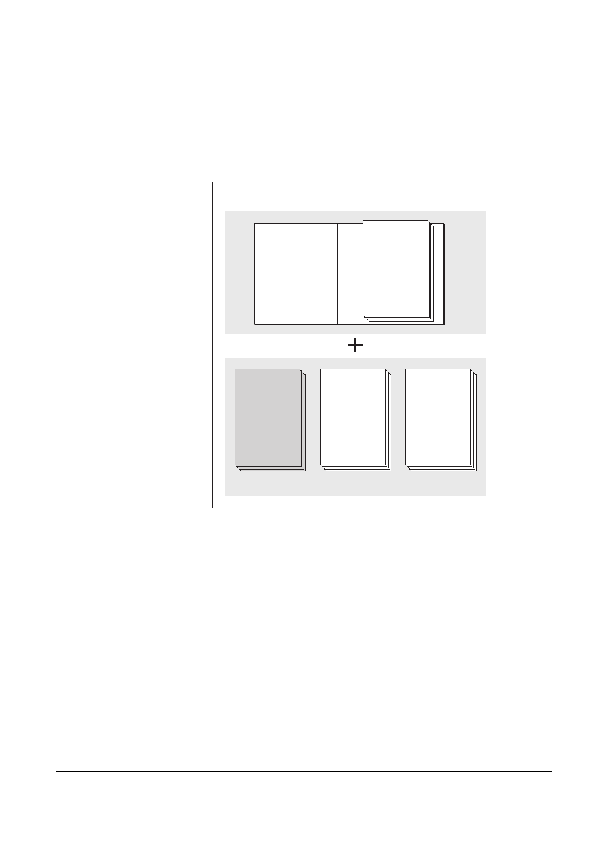
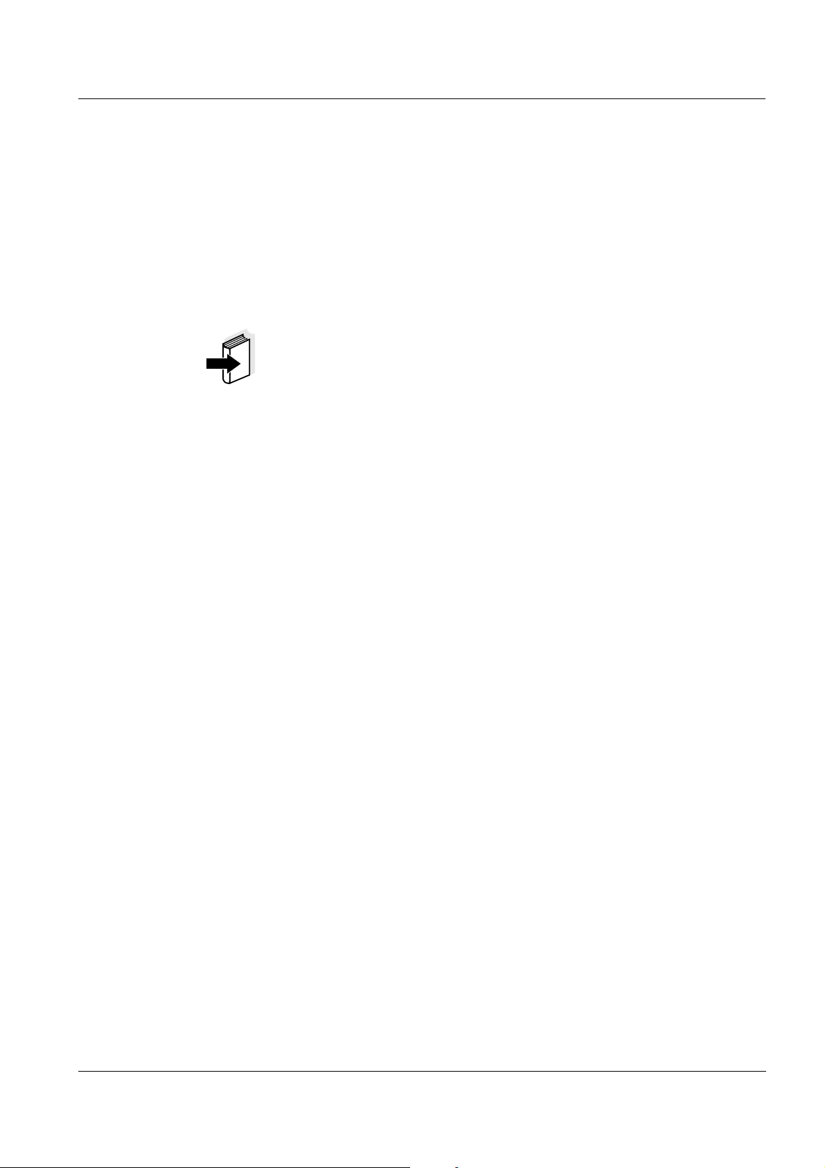
Structure of the
IQ SENSOR NET operating
manual
ba75950e02 11/2012
Fig. 1-1 Structure of the
IQ SENSOR NET operating manual
The IQ SENSOR NET operating manual has a modular structure like the
IQ S
ENSOR NET itself. It consists of a system operating manual and the
operating manuals of all the components used.
Please file this component operating manual into the ring binder of the
system operating manual.
1 - 1

Overview CarboVis 70x IQ TS
1.2 Fields of application
The range of application comprises control, feedback control and monitoring.
Measuring location
Ultrasound cleaning
system
Compressed air cleaning
(option)
CarboVis 701 IQ
TS
CarboVis 705 IQ
TS
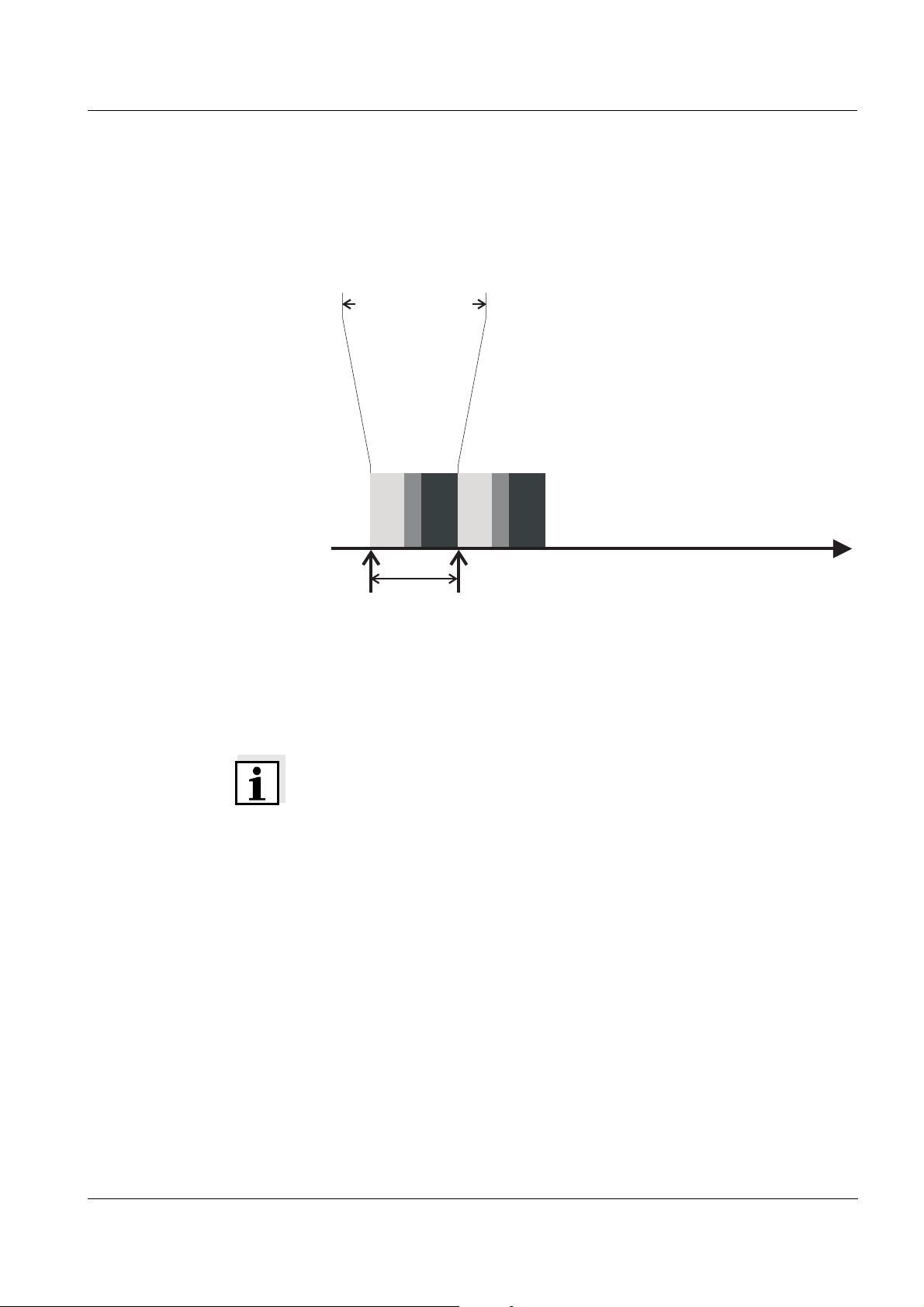
Inlet or outlet for higher parameter values (see
section 8.1 M
EASUREMENT CHARACTERISTICS)
Outlet for lower parameter values (see section
EASUREMENT CHARACTERISTICS)
8.1 M
The ultrasound cleaning system ensures low maintenance and longterm reliable measurement operation.
The ultrasound source integrated in the sensor excites the measurement windows to produce vibrations in the ultrasound range. The
movement of the surface as a result of this prevents the growth of
pollution in almost all cases and, thus, ensures reliable measured
values during continuous operation.
The sensor is designed to be equipped with an additional compressed
air-driven cleaning system, which supports the ultrasound cleaning
system as necessary.
1.3 Measuring principle of the UV-VIS sensor
The UV-VIS sensor operates according to the measuring principle of
UV-VIS spectrometry.
1 - 2
Any substance contained in a measuring solution attenuates a light
beam that penetrates the measuring solution. The attenuation (absorbance) of the light beam is measured for different wavelengths. The
wavelength dependent distribution produces the absorbance spectrum.
The wavelength range where an absorbance occurs is characteristic of
the substance. The extent of the absorbance depends on the amount
of the substance.
The influence of typical interference matrix variants occurring at municipal waste water treatment plants can be eliminated by including the
entire absorbance spectrum.
With this measuring principle, measuring does not take place continuously but at intervals.
ba75950e02 11/2012
CarboVis 70x IQ TS Overview
7
6
34
8
21 5
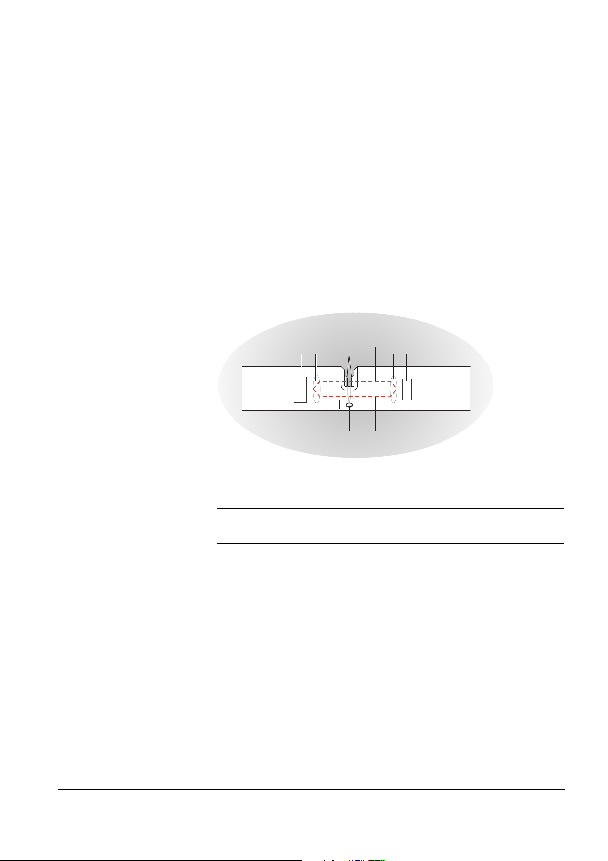
1.4 Structure of the UV-VIS sensor
A UV-VIS sensor contains a light source (1), a measuring gap (3) to
enable the contact of light with the measuring solution, and a detector
(5) to measure the attenuated light beam.
The sender of the optical system (2) directs a light beam, the measuring
beam (6), through the measuring solution and a second light beam, the
reference beam (8), over a distance without measuring solution. The
test sample is between both measurement windows (3) in the
measuring gap.
The receiver of the optical system (4) directs the measuring beam and
reference beam to the detector. In the detector, the light is received by
fixed photo diodes.
Fig. 1-2 Structure of a UV-VIS sensor
1 Light source
2 Sender of the optical system
3 Measuring gap between the measurement windows
4 Receiver of the optical system
5 Detector
6 Measuring beam
7 Reference beam
8 Connection for the optional compressed air cleaning system
ba75950e02 11/2012
1 - 3

Overview CarboVis 70x IQ TS
1 - 4
ba75950e02 11/2012
CarboVis 70x IQ TS Safety
2Safety
2.1 Safety information
2.1.1 Safety information in the operating manual
This operating manual provides important information on the safe operation of
the product. Read this operating manual thoroughly and make yourself familiar
with the product before putting it into operation or working with it. The operating
manual must be kept in the vicinity of the meter so you can always find the information you need.
Important safety instructions are highlighted in this operating manual. They are
indicated by the warning symbol (triangle) in the left column. The signal word
(e.g. "CAUTION") indicates the danger level:
WARNING
indicates a possibly dangerous situation that can lead to serious (irreversible)
injury or death if the safety instruction is not followed.
CAUTION
indicates a possibly dangerous situation that can lead to slight (reversible) injury
if the safety instruction is not followed.
Note
indicates a situation where goods might be damaged if the actions mentioned
are not taken.
2.1.2 Safety signs on the product
Note all labels, information signs and safety symbols on the product. A warning
symbol (triangle) without text refers to safety information in this operating
manual.
2.1.3 Further documents providing safety information
The following documents provide additional information, which you should
observe for your safety when working with the measuring system:
Operating manuals of other components of the IQ S
(power packs, controller, accessories)
ENSOR NET system
ba75950y01 11/2012
Safety datasheets of calibration and maintenance equipment (e.g. cleaning
solutions).
2 - 1

Safety CarboVis 70x IQ TS
2.2 Safe operation
2.2.1 Authorized use
The authorized use of the CarboVis 70x IQ TS consists of its use as a sensor in
the IQ S
the instructions and technical specifications given in this operating manual is
authorized (see chapter 8 T
thorized.
2.2.2 Requirements for safe operation
Note the following points for safe operation:
The product may only be operated according to the authorized use specified
The product may only be supplied with power by the energy sources men-
The product may only be operated under the environmental conditions men-
ENSOR NET. Only the operation and running of the product according to
ECHNICAL DATA). Any other use is considered unau-
above.
tioned in this operating manual.
tioned in this operating manual.
The product may not be opened.
2.2.3 Unauthorized use
The product must not be put into operation if:
it is visibly damaged (e.g. after being transported)
it was stored under adverse conditions for a lengthy period of time (storing
conditions, see chapter 8 T
ECHNICAL DATA).
2 - 2
ba75950y01 11/2012

CarboVis 70x IQ TS Commissioning
3 Commissioning
3.1 IQ SENSOR NET system requirements
Software statuses of the
controller and terminal
components
For cleaning with
compressed air via a relay
The operation of the CarboVis 70x IQ TS requires the following software versions in the IQ S
ENSOR NET:
DIQ/S 182 Controller software: Version 3.45 or higher
MIQ/MC2 Controller software: Version 3.37 or higher
MIQ TC 2020 XT Controller software: Version 3.37 or higher
IQ Software pack
ONNECT
C
Software version: Version 1.00 or higher
MIQ/CR3 Software version: Version 2.88 or higher
MIQ/R6 Software version: Version 2.88 or higher
MIQ/CHV PLUS Software version: Version 2.88 or higher
DIQ/S 182 (XT) Software version: Version 3.44 or higher
3.2 Scope of delivery of the CarboVis 70x IQ TS
The following parts are included in the scope of delivery of the
CarboVis 70x IQ TS:
UV-VIS sensor
Sensor sleeve
Shock protectors
Operating manual
ba75950e02 11/2012
3 - 1
Commissioning CarboVis 70x IQ TS
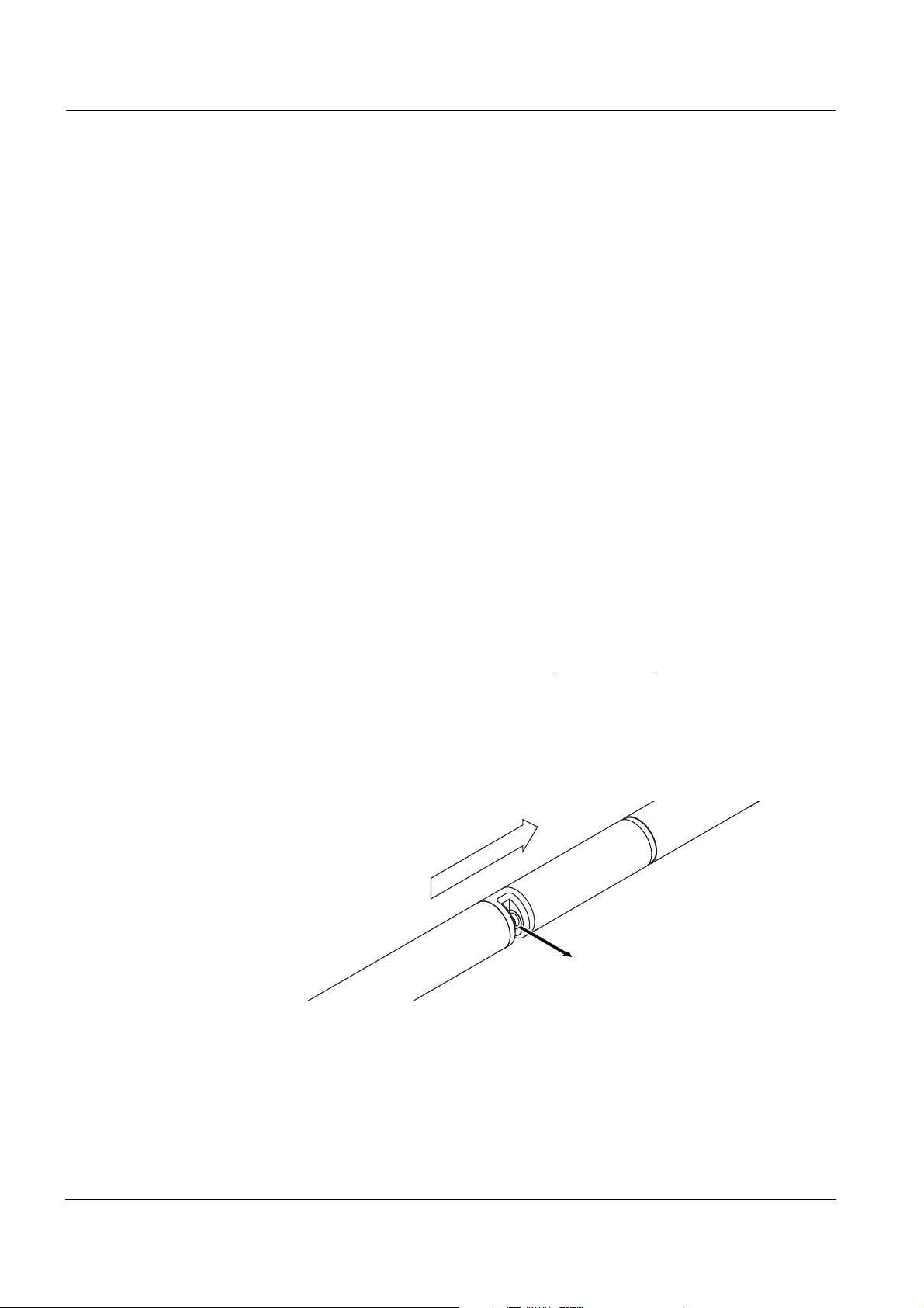
Measuring gap opening
Flow direction
3.3 Installation
3.3.1 Mounting the sensor
Note
The sensor is an optical precision instrument that is to be protected
against shocks. Make sure the distances to the wall, bottom and other
installation surroundings are sufficient. If necessary, protect the sensor
from hitting with the protective ring provided. Mount any fixing elements
only on the stable metal shaft.
Note
Always make sure the surface of the enclosure is not damaged by
sharp-edged objects. The enclosure of the sensor may not touch any
metallic objects in order to prevent contact corrosion.
Note
Do not suspend the sensor on the sensor connection cable. Risk of cable break and water penetration at the cable gland.
A wide range of mounting accessories is available for the installation of
the CarboVis 70x IQ TS (see chapter 6 S
EQUIPMENT, ACCESSORIES). Thus, all prevalent ways of mounting are
PARE PARTS, MAINTENANCE
possible.
Generally, observe the following general rules
when mounting the
sensor at the measuring location:
Horizontal installation When mounting the sensor horizontally, the measuring gap opening
should be on the side. Thus, any air bubbles can escape upward after
cleaning and no sediment can collect in the measuring gap. The sensor
should be aligned in parallel with the flow direction.
Fig. 3-1 Horizontal installation
3 - 2
ba75950e02 11/2012
CarboVis 70x IQ TS Commissioning
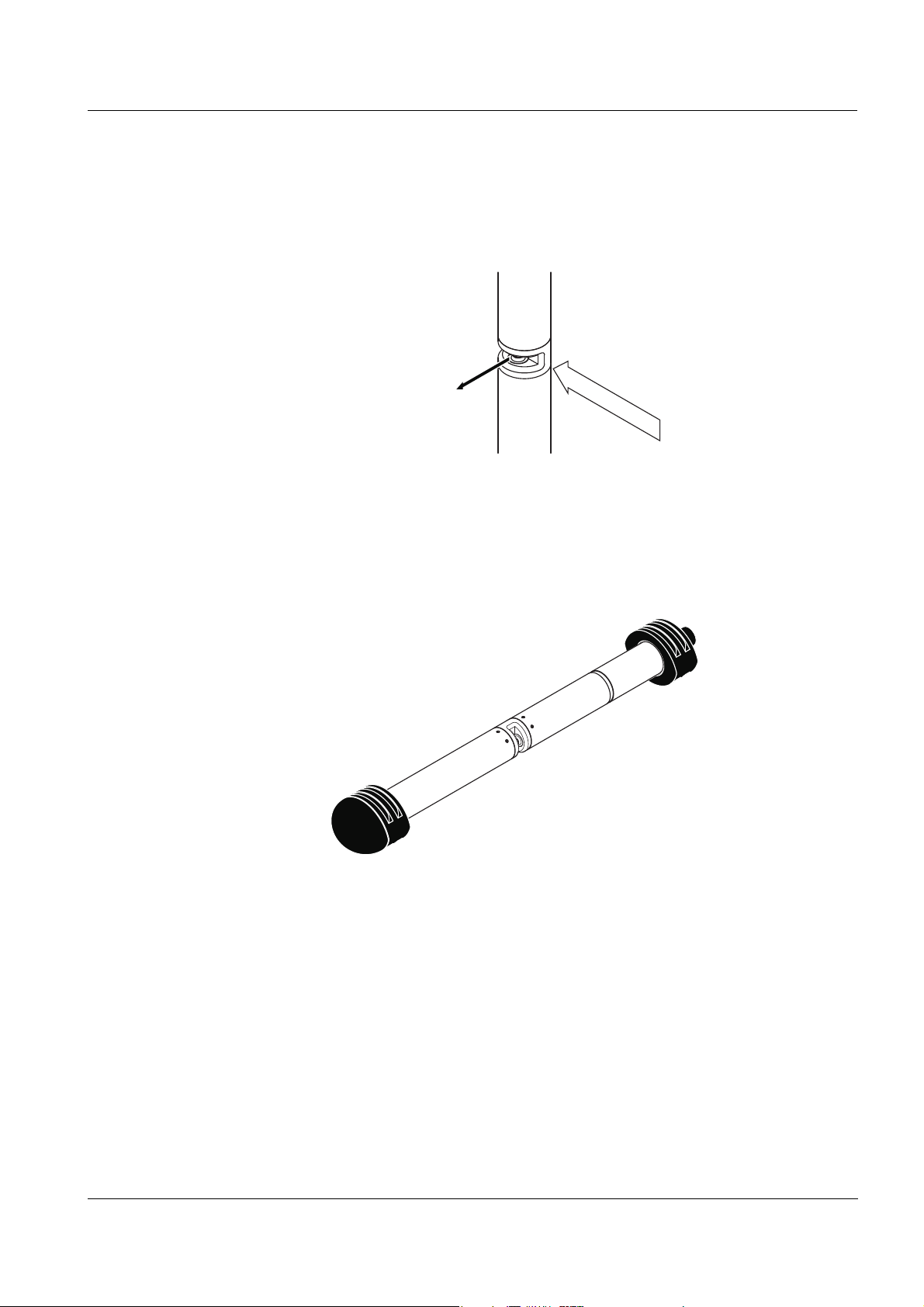
Flow direction
Vertical installation For vertical installation, mount the sensor in a position that allows inter-
fering elements in the measuring gap to escape with the current. In the
case of vertical installation, the minimum flow rate is 0.2 m/s so the
measuring gap is kept clean optimally.
Fig. 3-2 Vertical installation
Protection against shocks When installing the sensor, always make sure it cannot knock against
a wall or another obstacle. Make sure the safety margins are sufficient
(e. g. with suspended mounting).
Mount the enclosed shock protectors (see section 3.3.2). Their soft rubber compound absorbs hard impacts.
ba75950e02 11/2012
Fig. 3-3 Sensor with mounted shock protectors
3 - 3

Commissioning CarboVis 70x IQ TS
1
3
2
Sensor with mounted
shock protectors
3.3.2 Mounting the shock protectors
The shock protectors consist of two rings, a cap and four cable ties. To
mount the shock protectors, proceed as follows:
Fig. 3-4 Mounting the shock protectors
1. Plug the cap (pos. 2 in Fig. 3-4) on one of the two rings (pos. 1).
2. Put the assembled unit on the sensor end and fix it with 2 cable
ties (pos. 3) as shown in Fig. 3-4.
3. Put the second ring on the cable end of the sensor and fix it
with the remaining two cable ties in the same way.
3 - 4
ba75950e02 11/2012
CarboVis 70x IQ TS Commissioning
3.3.3 Connecting the sensor to the IQ SENSOR NET
Connection cable A sensor connection cable of the SACIQ or SACIQ SW type is required
to connect the sensor. The cable is available in different lengths.
Compared to the standard model SACIQ, the SACIQ SW sensor
connection cable is optimized regarding its corrosion resistance in
seawater and brackish water and adapted for use in conjunction with
the CarboVis 70x IQ TS . Information on this and other IQ S
ENSOR NET
accessories is given in the WTW catalog and on the Internet.
How to connect the SACIQ (SW) sensor connection cable to the terminal strip of an MIQ module is described in chapter 3 I
IQ S
ENSOR NET system operating manual.
NSTALLATION of the
Are the plug connections
dry?
Before connecting the sensor and sensor connection cable, please
make sure the plug connections are dry. If moisture gets into the plug
connections, first dry the plug connections (dab them dry or blow them
dry using compressed air).
Note
Do not suspend the sensor on the sensor connection cable but use the
suitable mounting equipment. Information on this and other
IQ S
ENSOR NET accessories is given in the WTW catalog and on the In-
ternet.
ba75950e02 11/2012
3 - 5

Commissioning CarboVis 70x IQ TS
SACIQ (SW)
1
2
Connecting the sensor to
the sensor connection
cable
1. Take the protective caps off the plug connections of the sensor
and the SACIQ (SW) sensor connection cable and keep them
safe.
2. Plug the socket of the SACIQ (SW) sensor connection cable
onto the plug head connector of the sensor. At the same time,
rotate the socket so that the pin in the plug head connector (1)
clicks into one of the two holes in the socket.
3. Then screw the coupling ring (2) of the sensor connection
cable onto the sensor up to the stop.
Fig. 3-5 Connecting the sensor
3 - 6
ba75950e02 11/2012
CarboVis 70x IQ TS Commissioning
3.4 Initial commissioning
3.4.1 General information
CAUTION
Never look into the measuring window or put objects into the measuring window during operation! The emitted UV radiation can damage the
eyes!
In the case of authorized use, inadvertent eye contact with the light
beam is not possible.
Measuring location The sensor is prepared for operation in the outlet of the waste water
treatment plant and calibrated in the factory. For use in the inlet you
only have to change the
The sensor is immediately ready to measure.
How to adjust the settings is described in the following section (section
3.4.3).
Measuring location
setting.
User calibration after initial
commissioning
On the basis of a reference measurement ("laboratory value"), check
whether the default settings deliver sufficiently accurate measured
values or whether you want to carry out a user calibration (see section
ALIBRATION).
4.3 C
ba75950e02 11/2012
3 - 7

Commissioning CarboVis 70x IQ TS
3.4.2 Sensor structure
The physical sensor is the sensor with the instrument or model designation, CarboVis 70x IQ TS. The physical sensor processes the measurement signal (absorbance spectrum) and supplies up to 5
measurement results to the IQ S
ENSOR NET. The measurement results
are administrated like 5 sensors that differ in hierarchy as follows:
Main sensor The sensor for carbon measurement is the main sensor.
It registers on the system under the designation, CarboVis 70x IQ TS
and the series number of the physical sensor.
Secondary sensor The sensor for the measurement of total suspended solids is the
secondary sensor.
It registers on the system under the designation, SolidVis 70x IQ and
the series number of the physical sensor.
Virtual sensors All other sensors for carbon measurement are virtual sensors.
You register on the system under the designation, CarboVis 70x IQ TS
and the series number of the physical sensor.
Sensor overlapping
settings and functions
Some settings and functions are sensor overlapping. Sensor overlapping settings are generally edited in the setting menu of the main sensor.
These are the most important sensor overlapping settings and functions:
Measuring location
Times of the measuring cycle (
Meas. interval, Cleaning duration, Adjustment phase
Signal smoothing
etc.)
Details on sensor overlapping functions are given in the following
section.
3 - 8
ba75950e02 11/2012
CarboVis 70x IQ TS Commissioning
Time
Adjustment time
Measurement
Measuring
cycle
Measuring interval
Cleaning
3.4.3 Settings for the main sensor
Measuring cycle A measuring cycle consists of the cleaning procedure, the adjustment
time for the measuring system and the determination of the measured
value. The following graphic demonstrates the relevant settings:
Fig. 3-6 Measuring cycle of the UV-VIS sensor
Carrying out settings Using <S>, switch from the measured value display to the main menu
of the settings. Then navigate to the setting menu (setting table) of the
sensor. The procedure is described in detail in your IQ S
ENSOR NET
system operating manual.
A change of the following settings will take some time (up to a few minutes) until it can be seen in the measured value display:
Measuring mode
Measuring location
Number of C-sensors
Further changes can only be made when the last changes are visible
in the measured value display.
Default values are marked in bold.
ba75950e02 11/2012
3 - 9

Commissioning CarboVis 70x IQ TS
Menu item Settings Explanations
Measuring mode
Measuring location
COD spectr., total
COD spectr., dissolv
TOC spectr., correl.
BOD spectr., correl.
DOC spectr., correl.
SAC 254, total
SAC 254, dissolved
UVT 254
Outlet
Inlet
Activation
The measured parameter is displayed
in the selected citation form.
When changing the
setting, always check the
location
If the previously set measurement location is not available for the selected
measuring mode, the measurement
location is automatically changed..
Measurement location or application of
the sensor.
The possible measurement loca-
The sample matrix on which the cal-
The measurement location
can only be selected for
mode
setting.
tions are displayed depending on the
currently set measuring mode.
culation of the measured value is
based changes with the location of
the sensor.
COD spectr., dissolv
Measuring mode
Measuring
Activation
Measuring
.
Measuring range -
Cal - # raw value 1
Cal - ref. value 1
Value pairs of the user calibration (see section 4.3.2).
Note:
Leave those values unchanged during the initial commission-
ing.
Cal - # raw value 2
Cal - ref. value 2
Zero adjustment Factory
User
Signal smoothing
On
Off
Display of the measuring range
(see chapter 8 T
Setting of which zero adjustment is
used in the sensor.
Factory zero adjustment or
Zero adjustment carried out last
Switching on/off the signal smoothing.
For more details, see
t90
.
ECHNICAL DATA).
Response time
3 - 10
ba75950e02 11/2012
 Loading...