

Page 1

User's
ROTAMASS 3-Series
Manual
addition to
IM 01R04B04-00E
Coriolis - Massflowmeter
Integral Type RCCT3
Remote Type RCCF31 + RCCS3
Fieldbus Communication Type
IM 01R04B05-00E-E
Rota Yokogawa GmbH & Co. KG
Rheinstr. 8
D-79664 Wehr
Germany
IM 01R04B05-00E-E
2nd edition, June 2007
Page 2

Blank Page
Page 3

CONTENTS
Contents
1. INTRODUCTION ..................................................................................1-1
1.1 Using the Coriolis Flowmeter Safely ...............................................................1-2
1.2 Warranty .............................................................................................................1-3
1.3 Instruction according EMC ............................................................................... 1-3
1.4 ATEX Documentation ........................................................................................ 1-4
1.5 Disposal, Cleaning and Return ........................................................................1-6
2. AMPLIFIER FOR FIELDBUS COMMUNICATION..............................2-1
3. ABOUT FIELDBUS ..............................................................................3-1
3.1 Outline ................................................................................................................ 3-1
3.2 Internal Structure of Rotamass ........................................................................3-1
3.2.1 System/Network Management VFD...................................................................... 3-1
3.2.2 Function Block VFD ............................................................................................... 3-1
3.3 Logical Structure of Each Block ......................................................................3-2
3.4 Wiring System Configuration ...........................................................................3-2
4. GETTING STARTED ...........................................................................4-1
4.1 Connection of Devices ..................................................................................... 4-1
4.2 Host Setting .......................................................................................................4-2
4.3 Power-on of Rotamass and Bus ...................................................................... 4-2
4.4 Integration of DD ...............................................................................................4-3
4.5 Reading the Parameters ...................................................................................4-3
4.6 Continuous Record of Values ..........................................................................4-3
4.7 Generation of Alarm...........................................................................................4-3
5. CONFIGURATION ................................................................................5-1
5.1 Network Design .................................................................................................5-1
5.2 Network Definition.............................................................................................5-1
5.3 Function Block Link Definitions.......................................................................5-2
5.4 Setting of Tags and Addresses ........................................................................5-3
5.5 Communication Setting ....................................................................................5-4
5.5.1 VCR Setting ............................................................................................................ 5-4
5.5.2 Function Block Execution Control ...................................................................... 5-5
5.6 Block Setting .....................................................................................................5-5
5.6.1 Link Objects ........................................................................................................... 5-5
5.6.2 Trend Objects ........................................................................................................ 5-5
5.6.3 View Objects .......................................................................................................... 5-6
5.6.4 AI Function Block Parameters ............................................................................ 5-12
All Rights Reserved, Copyright 2003. Rota Yokogawa GmbH & Co. KG
i
IM 01R04B05-00E-E
2nd edition, June 2007
Page 4

CONTENTS
6. IN-PROCESS OPERATION .................................................................6-1
6.1 Mode Transition .................................................................................................6-1
6.2 Generation of Alarm...........................................................................................6-1
6.2.1 Indication of Alarm ................................................................................................. 6-1
6.2.2 Alarms and Events ................................................................................................ 6-3
6.3 Simulation Function ..........................................................................................6-3
7. DEVICE STATUS ................................................................................ 7-1
8. GENERAL SPECIFICATIONS ............................................................8-1
9. EXPLOSION PROTECTED TYPE INSTRUMENTS ..........................9-1
9.1 ATEX .................................................................................................................. 9-1
9.1.1 Technical Data ....................................................................................................... 9-1
9.1.2 Installation .............................................................................................................. 9-3
9.1.3 Operation................................................................................................................ 9-5
9.1.4 Maintenance and repair ........................................................................................ 9-5
9.1.5 Name Plates ........................................................................................................... 9-5
9.1.6 I.S. fieldbus system complying with FISCO ......................................................... 9-7
9.2 FM .......................................................................................................................9-9
9.2.1 Technical Data ....................................................................................................... 9-9
9.2.2 Installation ............................................................................................................ 9-10
9.2.3 General warnings .................................................................................................9-11
9.2.4 Name Plates ......................................................................................................... 9-12
9.2.5 Control drawings ................................................................................................. 9-13
9.3 IECEx ................................................................................................................9-16
9.3.1 Technical Data ..................................................................................................... 9-16
9.3.2 Installation ............................................................................................................ 9-18
9.3.3 Operation.............................................................................................................. 9-19
9.3.4 Maintenance and repair ...................................................................................... 9-19
9.3.5 Name Plates ......................................................................................................... 9-19
9.3.6 I.S. fieldbus system complying with FISCO (only /EF4).................................... 9-22
9.4 INMETRO (Brazil).............................................................................................9-22
APPENDIX 1. LIST OF PARAMETERS FOR EACH BLOCK OF
Rotamass ............................................................................................ A-1
A1.1 Resource Block ................................................................................................ A-1
A1.2 Al Function Block .............................................................................................. A-4
A1.3 Transducer Block .............................................................................................. A-8
A1.4 Intergartor (IT) Block........................................................................................ A-14
APPENDIX 2. APPLICATION, SETTING AND CHANGE OF BASIC PA-
RAMETERS ....................................................................................... A-27
A2.1 Applications and Selection of Basic Parameters............................................. A-27
A2.2 Setting and Change of
Basic Parameters............................................................................................... A-28
A2.3 Setting the AI Function Blocks ......................................................................... A-28
A2.4 Setting the Transducer Block .......................................................................... A-30
IM 01R04B05-00E-E
2nd edition, June 2007
ii
Page 5

CONTENTS
APPENDIX 3. OPERATION OF EACH PARAMETER IN FAILURE MODE
A-33
APPENDIX 4. FUNCTION DIAGRAMS OF FUNCTION BLOCKS .... A-41
A4.1 AI Function Block......................................................................................... A-41
APPENDIX 5. PID BLOCK .................................................................. A-43
A5.1 Function Diagram ........................................................................................ A-43
A5.2 Functions of PID Block ............................................................................... A-43
A5.3 Parameters of PID Block ............................................................................. A-44
A5.4 PID Computation Details ............................................................................. A-46
A5.4.1 PV-proportional and -derivative Type PID (I-PD) Control Algorithm versus PV-
derivative Type PID (PI-D) Control Algorithm ....................................................... A-46
A5.4.2 PID Control Parameters .................................................................................... A-46
A5.5 Control Output ............................................................................................. A-46
A5.5.1 Velocity Type Output Action .............................................................................. A-46
A5.6 Direction of Control Action .......................................................................... A-46
A5.7 Control Action Bypass ................................................................................ A-47
A5.8 Feed-forward ................................................................................................ A-47
A5.9 Block Modes................................................................................................. A-47
A5.9.1 Mode Transitions............................................................................................... A-48
A5.10 Bumpless Transfer .................................................................................... A-48
A5.11 Setpoint Limiters ........................................................................................ A-48
A5.11.1 When PID Block Is in AUTO Mode ................................................................. A-48
A5.11.2 When PID Block Is in CAS or RCAS Mode .................................................... A-48
A5.12 External-output Tracking........................................................................... A-49
A5.13 Measured-value Tracking .......................................................................... A-49
A5.13.1 CONTROL_OPTS ............................................................................................ A-49
A5.14 Initialization and Manual Fallback (IMAN) ................................................ A-49
A5.15 Manual Fallback ......................................................................................... A-50
A5.15.1 STATUS_OPTS ................................................................................................ A-50
A5.16 Auto Fallback .............................................................................................. A-50
A5.17 Mode Shedding upon Computer Failure ................................................. A-50
A5.17.1 SHED_OPT ....................................................................................................... A-50
A5.18 Alarms ......................................................................................................... A-51
A5.18.1 Block Alarm (BLOCK_ALM) ............................................................................ A-51
A5.18.2 Process Alarms ................................................................................................ A-51
A5.19 Example of Block Connections ................................................................ A-52
APPENDIX 6. SOFTWARE DOWNLOAD ........................................... A-53
iii
IM 01R04B05-00E-E
2nd edition, June 2007
Page 6

CONTENTS
APPENDIX 7. LINK MASTER FUNCTIONS ....................................... A-61
A7.1 Link Active Scheduler ..................................................................................... A-61
A7.2 Link Master..................................................................................................... A-61
A7.3 Transfer of LAS .............................................................................................. A-62
A7.4 LM Functions .................................................................................................. A-63
A7.5 LM Parameters .............................................................................................. A-64
A7.5.1 LM Parameter List ............................................................................................. A-64
A7.5.2 Descriptions for LM Parameters ..................................................................... A-66
(1) DlmeLinkMasterCapabilitiesVariable ............................................................... A-66
(2) DlmeLinkMasterInfoRecord .............................................................................. A-66
(3) PrimaryLinkMasterFlagVariable ........................................................................ A-66
(4) LiveListStatusArrayVariable .............................................................................. A-66
(5) MaxTokenHoldTimeArray .................................................................................. A-66
(6) BootOperatFunctionalClass .............................................................................. A-66
(7) CurrentLinkSettingRecord and ConfiguredLinkSettingsRecord ................. A-66
(8) DlmeBasicInfo ..................................................................................................... A-67
(9) PlmeBasicCharacteristics ................................................................................. A-67
(10) ChannelStates .................................................................................................. A-67
(11) PlmeBasicInfo ................................................................................................... A-67
(12) LinkScheduleActivationVariable ..................................................................... A-67
(13) LinkScheduleListCharacteristicsRecord ...................................................... A-67
(14) DlmeScheduleDescriptor ................................................................................ A-68
(15) Domain ............................................................................................................... A-68
A7.6 FAQs.............................................................................................................. A-68
APPENDIX 8. DEVICEVIEWER WINDOW EXECUTED FROM PRM
(Plant Resource Manager) ............................................................. A-71
IM 01R04B05-00E-E
2nd edition, June 2007
iv
Page 7

1. INTRODUCTION
T
1. INTRODUCTION
This instrument has been adjusted at the factory
before shipment.
To ensure correct use of the instrument, please
read this manual thoroughly and fully understand
how to operate the instrument before operating it.
NOTE
This manual describes the hardware and software configurations of the Rotamass Coriolis
Massflowmeter.
Regarding This User's Manual
• This manual should be provided to the end
user.
• Before use, read this manual thoroughly to
comprehend its contents.
• The contents of this manual may be changed
without prior notice.
• All rights are reserved. No part of this manual
may be reproduced in any form without
Yokogawa's written permission.
• Yokogawa makes no warranty of any kind with
regard to this material, including, but not limited
to, implied warranties of merchantability and
suitability for a particular purpose.
• All reasonable effort has been made to ensure
the accuracy of the contents of this manual.
However, if any errors or omissions are found,
please inform Yokogawa.
• Yokogawa assumes no responsibilities for this
product except as stated in the warranty.
• Please note that this user's manual may not be
revised for any specification changes,
construction changes or operating part changes
that are not considered to affect function or
performance.
• If the customer or any third party is harmed by
the use of this product, Yokogawa assumes no
responsibility for any such harm owing to any
defects in the product which were not
predictable, or for any indirect damages.
Safety and Modification Precautions
• The following general safety precautions must be
observed during all phases of operation, service,
and repair of this instrument. Failure to comply
with these precautions or with specific
WARNINGS given elsewhere in this manual
violates safety standards of design,manufacture,
and intended use of the instrument. Yokogawa
assumes no liability for the customer's failure to
comply with these requirements. If this
instrument is used in a manner not specified in
this manual, the protection provided by this
instrument may be impaired.
• The following safety symbol marks are used in
this user's manual and instrument.
WARNING
A WARNING sign denotes a hazard. It calls
attention to procedure, practice, condition or the
like, which, if not correctly performed or adhered
to, could result in injury or death of personnel.
CAUTION
A CAUTION sign denotes a hazard. It calls
attention to procedure, practice, condition or the
like, which, if not correctly performed or adhered
to, could result in damage to or destruction of
part or all of the product.
IMPORTAN
An IMPORTANT sign denotes that attention is
required to avoid damage to the instrument or
system failure.
NOTE
A NOTE sign denotes information necessary for
essential understanding of operation and features.
1-1
IM 01R04B05-00E-E
2nd edition, June 2007
Page 8

1. INTRODUCTION
Protective grounding terminal
Functional grounding terminal
(This terminal should not be used as a
protective grounding terminal.)
Alternating current
Direct current
1.1 Using the Coriolis Flowmeter Safely
WARNING
(1) Installation
• Installation of the Coriolis flowmeter must be
performed by expert engineer or skilled personnel. No operator shall be permitted to perform
procedures relating to installation.
• The Coriolis flowmeter is a heavy instrument.
Be careful that no damage is caused to personnel through accidentally dropping it, or by
exerting excessive force on the Coriolis
flowmeter. When moving the Coriolis flowmeter,
always use a trolley and have at least two
people carry it.
• When the Coriolis flowmeter is processing hot
fluids, the instrument itself may become
extremely hot. Take sufficient care not to get
burnt.
• Where the fluid being processed is a toxic
substance, avoid contact with the fluid and
avoid inhaling any residual gas, even after the
instrument has been taken off the line for
maintenance and so forth.
• All procedures relating to installation must
comply with the electrical code of the country
where it is used.
(2) Wiring
• The wiring of the Coriolis flowmeter must be
performed by expert engineer or skilled personnel. No operator shall be permitted to perform
procedures relating to wiring.
• When connecting the wiring, check that the
supply voltage is within the range of the voltage
specified for this instrument before connecting
the power cable. In addition, check that no
voltage is applied to the power cable before
connecting the wiring.
• The protective grounding must be connected
securely at the terminal with the mark to
avoid danger to personnel.
(3) Operation
• Do not open the cover until the power has been
off for at least 10 minutes. Only expert engineer
or skilled personnel are permitted to open the
cover.
(4) Maintenance
• Maintenance on the Coriolis flowmeter should
be performed by expert engineer or skilled
personnel. No operator shall be permitted to
perform any operations relating to maintenance.
• Always conform to maintenance procedures
outlined in this manual. If necessary, contact
Yokogawa.
• Care should be taken to prevent the build up of
dirt, dust or other substances on the display
panel glass or data plate. If these surfaces do
get dirty, wipe them clean with a soft dry cloth.
(5) European Pressure Equipment Directive (PED)
• When using the instrument as a PED-compliant
product, be sure to read Chapter 10 before use.
(6) Hazardous Duty Type Instruments
• For explosion proof type instruments the
description in chapter 9 "EXPLOSION
PROTECTED TYPE INSTRUMENT" has
priority to the other descriptions in this instruction
manual.
• All instruction manuals for ATEX Ex related
products are availabel in English, German and
French. Should you require Ex related instructions
in your local language, you should contact
your nearest Yokogawa office or representative.
• Only trained personal should install and
maintain instruments in hazardous areas.
• The protective grounding terminal must be
connected to a suitable IS grounding system.
• Avoid mechanical generated sparks while
working on the equipment and peripherial
devices in hazardous areas.
IM 01R04B05-00E-E
2nd edition, June 2007
1-2
Page 9

1. INTRODUCTION
T
1.2 Warranty
• The warranty terms of this instrument that are
guaranteed are described in the quotation. We
will make any repairs that may become
necessary during the guaranteed term free of
charge.
• Please contact our sales office if this instrument
requires repair.
• If the instrument is faulty, contact us with
complete details about the problem and the
length of time it has been faulty, and state the
model and serial number. We would appreciate
the inclusion of drawings or additional information.
• The results of our examination will determine
whether the meter will be repaired free of
charge or on an at-cost basis.
The guarantee will not apply in the following
cases:
• Damage due to negligence or insufficient
maintenance on the part of the customer.
• Problems or damage resulting from handling,
operation or storage that violates the intended
use and specifications.
• Problems that result from using or performing
maintenance on the instrument in a location that
does not comply with the installation location
specified by Yokogawa.
• Problems or damage resulting from repairs or
modifications not performed by Yokogawa or
someone authorized by Yokogawa.
• Problems or damage resulting from inappropriate installation after delivery.
• Problems or damage resulting from disasters
such as fires, earthquakes, storms, floods, or
lightning strikes and external causes.
1.3 Instruction
according EMC
The ROTAMASS Coriolis flowmeter is conform to
the European EMC Guideline and fulfills the
following standards:
- EN 61326-1
- EN 55011
- EN 61000-3-2
- EN 61000-3-3
ROTAMASS is a class A product and should be
used and installed properly according to the EMC
Class A requirements
Restriction on Use of Radio Transceiver :
IMPORTAN
Although the products has been designed to
resist high frequency electrical noise, if a radio
transceiver is used near the flowmeter or its
external wiring, the transmitter may be affected by
high frequency noise pickup. To test for such
effects, bring the transceiver in use slowly from a
distance of several meters from the flowmeter,
and observe the measurement loop for noise
effects. Thereafter, always use the transceiver
outside the area affected by noise.
Installation
CAUTION
The function ground terminal or the PE-terminal
have to be connected to protective ground to
ensure electro-magnetic interference protection.
To ensure the EMC specifications the following
measures must be carried out :
1. Put the power cables through the ferrite core
clamp before connecting to the terminals as
shown in chapter ´ Installation ´(Power supply
wiring).
2. Put the I/O- cables through the ferrite core
clamp before connecting to the terminals as
shown in chapter ´ Installation ´(Power supply
wiring).
3. Connect protective ground conductor of power
supply to PE-terminal in the terminal box (see
chapter ´ Installation ´(Power supply wiring).
4. In case of Explosion proof type instrument,
further requirements are described in chapter 9
“EXPLOSION PROTECTED TYPE INSTRUMENT”.
The description in this chapter is prior to other
descriptions in this instruction manual.
1-3
IM 01R04B05-00E-E
2nd edition, June 2007
Page 10

1. INTRODUCTION
1.4 ATEX Documentation
This procedure is only applicable to the countries
in European Union.
GB
All instruction manuals for ATEX Ex related
products are available in English, German and
French. Should you require Ex related instructions
in your local language, you are to contact your
nearest Yokogawa office or representative.
DK
Alle brugervejledninger for produkter relateret til
ATEX Ex er tilgængelige på engelsk, tysk og
fransk. Skulle De ønske yderligere oplysninger om
håndtering af Ex produkter på eget sprog, kan De
rette henvendelse herom til den nærmeste
Yokogawa afdeling eller forhandler.
SF
Kaikkien ATEX Ex -tyyppisten tuotteiden
käyttöhjeet ovat saatavilla englannin-, saksan- ja
ranskankielisinä. Mikäli tarvitsette Ex -tyyppisten
tuotteiden ohjeita omalla paikallisella kielellännne,
ottakaa yhteyttä lähimpään Yokogawa-toimistoon
tai -edustajaan.
P
Todos os manuais de instruções referentes aos
produtos Ex da ATEX estão disponíveis em
Inglês, Alemão e Francês. Se necessitar de
instruções na sua língua relacionadas com
produtos Ex, deverá entrar em contacto com a
delegação mais próxima ou com um representante
da Yokogawa.
F
I
Tutti i manuali operativi di prodotti ATEX
contrassegnati con Ex sono disponibili in inglese,
tedesco e francese. Se si desidera ricevere i
manuali operativi di prodotti Ex in lingua locale,
mettersi in contatto con l’ufficio Yokogawa più
vicino o con un rappresentante.
E
Todos los manuales de instrucciones para los
productos antiexplosivos de ATEX están
disponibles en inglés, alemán y francés. Si desea
solicitar las instrucciones de estos artículos
antiexplosivos en su idioma local, deberá ponerse
en contacto con la oficina o el representante de
Yokogawa más cercano.
NL
Alle handleidingen voor producten die te maken
hebben met ATEX explosiebeveiliging (Ex) zijn
verkrijgbaar in het Engels, Duits en Frans. Neem,
indien u aanwijzingen op het gebied van
explosiebeveiliging nodig hebt in uw eigen taal,
contact op met de dichtstbijzijnde vestiging van
Yokogawa of met een vertegenwoordiger.
Tous les manuels d’instruction des produits ATEX
Ex sont disponibles en langue anglaise, allemande
et française. Si vous nécessitez des instructions
relatives aux produits Ex dans votre langue,
veuillez bien contacter votre représentant
Yokogawa le plus proche.
D
Alle Betriebsanleitungen für ATEX Ex bezogene
Produkte stehen in den Sprachen Englisch,
Deutsch und Französisch zur Verfügung. Sollten
Sie die Betriebsanleitungen für Ex-Produkte in
Ihrer Landessprache benötigen, setzen Sie sich
bitte mit Ihrem örtlichen Yokogawa-Vertreter in
Verbindung.
S
Alla instruktionsböcker för ATEX Ex
(explosionssäkra) produkter är tillgängliga på
engelska, tyska och franska. Om Ni behöver
instruktioner för dessa explosionssäkra produkter
på annat språk, skall Ni kontakta närmaste
Yokogawa kontor eller representant.
IM 01R04B05-00E-E
2nd edition, June 2007
1-4
Page 11

1. INTRODUCTION
j
GR
Ολα τα εγχειριδια λειτουργιαζ τωυ προιουτϖυ µε
ΑΤΕX Εx διατιΘευται στα Αγγλικα, Γερµαυικα
και Γαλλικα. Σε περιπτωση που χρειαζεοτε
οδηγιεζ σχετικα µε Ex στηυ τοπικη γλωσσα
παρακαλουµε επικοιυωυηστε µε το πλησιεστερο
γραϕειο τηζ Yokogawa η αντιπροσωπο τηζ.
SK
Všetky návody na obsluhu pre prístroje s ATEX
Ex sú k dispozícii v jazyku anglickom, nemeckom
a francúzskom. V prípade potreby návodu pre Exprístroje vo Vašom národnom jazyku, skontaktujte
prosím miestnu kanceláriu firmy Yokogawa.
CZ
Všechny uživatelské příručky pro výrobky, na
něž se vztahuje nevýbušné schválení ATEX Ex,
sou dostupné v angličtině , němčině a francouzštině .
Požadujete-li pokyny týkající se výrobků s
nevýbušným schválením ve vašem lokálním jazyku,
kontaktujte prosím vaši nejbližší reprezentační
kancelář Yokogawa.
PL
Wszystkie instrukcje obsługi dla urządzeń
w wykonaniu przeciwwybuchowym Ex,
zgodnych z wymaganiami ATEX, dostępne
są w języku angielskim, niemieckim i
francuskim. Jeżeli wymagana jest instrukcja
obsługi w Państwa lokalnym ję zyku, prosimy
o kontakt z najbliższym biurem Yokogawy.
SLO
Vsi predpisi in navodila za ATEX Ex sorodni
pridelki so pri roki v anglišèini, nemšèini ter
francošèini. Èe so Ex sorodna navodila potrebna
v vašem tukejnjem jeziku, kontaktirajte vaš najbliši
Yokogawa office ili predstaunika.
H
Az ATEX Ex mûszerek gépkönyveit angol, német
és francia nyelven adjuk ki. Amennyiben helyi
nyelven kérik az Ex eszközök leírásait, kérjük
keressék fel a legközelebbi Yokogawa irodát, vagy
képviseletet.
BG
LT
Visos gaminiø ATEX Ex kategorijos
Eksploatavimo instrukcijos teikiami anglø,
vokieèiø ir prancûzø kalbomis. Norëdami gauti
prietaisø Ex dokumentacijà kitomis kalbomis
susisiekite su artimiausiu bendrovës “Yokogawa”
biuru arba atstovu.
LV
Visas ATEX Ex kategorijas izstrâdâjumu
Lietoðanas instrukcijas tiek piegâdâtas angïu,
vâcu un franèu valodâs. Ja vçlaties saòemt Ex
ierîèu dokumentâciju citâ valodâ, Jums ir
jâsazinâs ar firmas Jokogava (Yokogawa) tuvâko
ofisu vai pârstâvi.
EST
Kõik ATEX Ex toodete kasutamisjuhendid on
esitatud inglise, saksa ja prantsuse keeles. Ex
seadmete muukeelse dokumentatsiooni
saamiseks pöörduge lähima Iokagava
(Yokogawa) kontori või esindaja poole.
Всички упътвания за продукти от серията АТЕХ
Ех се предлагат на английски, немски и
френски език. Ако се нуждаете от упътвания
за продукти от серията Ех на родния ви език,
се свържете с най-близкия офис или
представителство на фирма Yokogawa.
RO
Toate manualele de instructiuni pentru produsele
ATEX Ex sunt in limba engleza, germana si
franceza. In cazul in care doriti instructiunile in
limba locala, trebuie sa contactati cel mai apropiat
birou sau reprezentant Yokogawa.
M
Il-manwali kollha ta’ l-istruzzjonijiet għal prodotti
marbuta ma’ ATEX Ex huma disponibbli bl-Ingliż,
bil-Ġermaniż u bil-Franċiż. Jekk tkun teħtieġ
struzzjonijiet marbuta ma’ Ex fil-lingwa lokali tiegħek,
għandek tikkuntattja lill-eqreb rappreżentan jew
uffiċċju ta’ Yokogawa.
1-5
IM 01R04B05-00E-E
2nd edition, June 2007
Page 12

1. INTRODUCTION
1.5 Disposal, Cleaning
and Return
For safe use
WARNING
If the process fluid is harmful to personnel, handle
the instrument carefully even after it has been
removed from the process line for maintenance or
other purposes. Exercise extreme care to prevent
the fluid from coming into contact with human skin
and to avoid inhaling any residual gas. Before
sending it to the Seller for examination and/or
repair please clean the instrument thoroughly and
make sure, that no harmful chemicals are in or at
the meter. If the instrument contains unknown
fluids the Seller will send it back to the Purchaser
for cleaning on their cost.
WARNING
ROTAMASS might be heavy instruments. Please
give attention to prevent that persons are not
injured by carrying or installing. It is preferable
when carrying the instrument to use a cart and be
done by two or more persons. When removing
the instrument from hazardous processes, avoid
contact with the fluid and the interior of the meter.
the failure occurred. It will be helpful if schematic
diagrams and/or records of data are attached to
the failed instrument. Whether or not the failed
instrument should be repaired free of charge shall
be left solely to the discretion of the Seller as a
result of an inspection by the Seller.
The Purchaser shall not be entitled to receive
repair services from the Seller free of charge,
even during the warranty period, if the malfunction
or damage is due to improper and/or inadequate
maintenance of the instrument in question by the
Purchaser handling, use or storage of the
instrument in question beyond the design and/or
specifications requirements, use of the
instrument in question in a location no conforming
to the conditions specified in the Seller’s General
Specification or Instruction Manual retrofitting and/
or repair by an other party than the Seller or a
party to whom the Seller has entrusted repair
services. improper relocation of the instrument in
question after delivery reason of force measure
such as fires, earthquakes, storms/ floods,
thunder/lightning, or other reasons not attributable
to the instrument in question.
For disposal and recycling please refer to your
national regulations.
Please find following help. After remove of all
products rests the instruments can be
disassembled and the parts treated different.
Warranty
The warranty of the instruments shall cover the
period noted on the quotation presented to the
purchaser at the time of purchase. The Seller
shall repair the instrument free of charge when
the failure occurred during the warranty period.
All inquiries on instrument failure should be
directed to the Seller’s sales representative from
whom you purchased the instrument or your
nearest sales office of the Seller.
Should the instrument fail, contact the Seller,
specifying the model and instrument number of
the product in question. Be specific in describing
details on the failure and the process in which
IM 01R04B05-00E-E
2nd edition, June 2007
Naming: R = recycling, D = disposal, Sd = special
disposal, Na = not applicable
Name of
Product
Rotamass
Body Converter
housing
SS R Al R
Cap with
window
Al +
glass
In case of return of flowmeters to Yokogawa for
testing or repair purposes please fillout one of the
following forms and send it with the equipment to
YOKOGAWA.
1-6
D
Electronics
Sd
T1.EPS
Page 13

Receiver : Sender :
Delivery Note (for EU-Countries) Date :
Ref. REPAIR for serial no. __________________________
We are sending following type of article
via forwarding agent : Yusen Air ; Raunheim/Frankfurt
Item Article Unit Price Total Price
Type (MS-Code)
________________________________ € __________ €__________
(nominal value)
Charges for airworthy packing
and delivery FOB €___________
Total value € ___________
1. INTRODUCTION
Value for customs purpose only € _________
(current value)
Gross weight . _____________________kg
Net weight : _____________________kg
Customs Tariff No. : _____________________
Country og origin : Federal Republic of Germany
Delivery note 2-fold accompanis the goods
SPECIMEN Certificate
Company : ________________________ Address : ______________________
Department : ________________________ Name : ______________________
Telephone : ________________________ Fax : ______________________
The attached flowmeter :
Type : ______________________________ Order- or Serial No. ___________
has been operated with following liquids: ___________________________________________
Because the liquid is water-endangering toxic caustic flammable
we have
checked, that all cavities in the flowmeter are free from such substances
flushed out and neutralised all cavities in the flowmeter
Please check applicable description
We confirm that there is no risk to man or enviroment through any residual liquid containes in this flowmeter.
Date : _____________________ Signature : _______________________
Company stamp:
1-7
IM 01R04B05-00E-E
2nd edition, June 2007
Page 14

1. INTRODUCTION
Receiver : Sender :
PROFORMA INVOICE (for Third-party-Countries) Date :
Ref. REPAIR for serial no. __________________________
We are sending following type of article
via forwarding agent : Yusen Air ; Raunheim/Frankfurt
Item Article Unit Price Total Price
Type (MS-Code)
________________________________ € __________ €__________
(nominal value)
Charges for airworthy packing
and delivery FOB €___________
Total value € ___________
Value for customs purpose only € _________
(current value)
Gross weight . _____________________kg
Net weight : _____________________kg
Customs Tariff No. : _____________________
Country og origin : Federal Republic of Germany
Delivery note 2-fold accompanis the goods
SPECIMEN Certificate
Company : ________________________ Address : ______________________
Department : ________________________ Name : ______________________
Telephone : ________________________ Fax : ______________________
The attached flowmeter :
Type : ______________________________ Order- or Serial No. ___________
has been operated with following liquids: ___________________________________________
Because the liquid is water-endangering toxic caustic flammable
we have
checked, that all cavities in the flowmeter are free from such substances
flushed out and neutralised all cavities in the flowmeter
Please check applicable description
We confirm that there is no risk to man or enviroment through any residual liquid containes in this flowmeter.
Date : _____________________ Signature : _______________________
Company stamp:
IM 01R04B05-00E-E
2nd edition, June 2007
1-8
Page 15
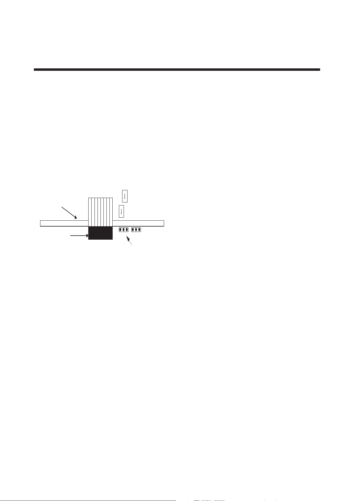
2. AMPLIFIER FOR FIELDBUS COMMUNICATION
2. AMPLIFIER FOR FIELDBUS
COMMUNICATION
Refer to IM 01R04B04-00E for the details of the
amplifier. This section encompasses topics
applicable to only the Fieldbus communication
type.
(1) The Fieldbus communication type has no local
key access function.
(2) The Fieldbus communication type has no
HART terminal connection pin.
(3) The Fieldbus communication type has a
simulation function. The SIMULATE_ENABLE
jumper is mounted on the amplifier. Refer to
Section 6.3, “Simulation Function” for details of
the simulation function.
Std
FF Board
Simu
Cable to display
JP1 (Simulate_Enable)
Figure 2.1 Amplifier for Fieldbus Communication
F0201.EPS
2-1
IM 01R04B05-00E-E
2nd edition, June 2007
Page 16

2. AMPLIFIER FOR FIELDBUS COMMUNICATION
Blank Page
IM 01R04B05-00E-E
2nd edition, June 2007
2-2
Page 17

3. ABOUT FIELDBUS
3. ABOUT FIELDBUS
3.1 Outline
Fieldbus is a bi-directional digital communication
protocol for field devices, which offers an advancement in implementation technologies for
process control systems and is widely employed
by numerous field devices.
The Fieldbus communication type of the Rotamass
employs the specification standardized by the
Fieldbus FOUNDATION, and provides interoperability
between Yokogawa devices and those produced
by other manufacturers. Featuring 6 AI and two IT
function blocks in each, the Fieldbus communication type’s software enables a flexible instrumentation system to be implemented.
For information on other features, engineering,
design, construction work, startup and maintenance of Fieldbus, refer to “Fieldbus Technical
Information” (TI 38K3A01-01E).
3.2 Internal Structure of
ROTAMASS
Each Rotamass contains two Virtual Field Devices
(VFDs) that share the following functions.
3.2.1 System/Network Management VFD
• Sets node addresses and Physical Device
tags (PD Tag) necessary for communication.
• Controls the execution of function blocks.
• Manages operation parameters and
communication resources (Virtual
Communication Relationship: VCR).
- Converts the flow sensor output to the
process fluid density and transfers to an AI
function block (AI3).
- Converts temperature sensor output to the
process fluid temperature and transfers to
an AI function block (AI4).
- Calculates the volumetric flow rate from
the fluid density and the mass flow rate
and transfers to an AI function block (AI2).
(3) AI function blocks (six)
• The AI blocks condition raw data from the
transducer block, including scaling and
damping (with a first-order lag), and allow
input simulation.
• AI1 outputs mass flow rate signals, and AI2
outputs volumetric flow rate signals.
• AI3 outputs density signals, and AI4 outputs
temperature signals.
• AI5 outputs concentration measurement
signals (option), and AI6 outputs net flow
rate signals (option).
(4) IT Integrator blocks (two)
• IT1 totalizes mass-, volume or net flow rate.
• IT2 totalizes mass-, volume or net flow rate.
(5) PID function block (optional)
• Performs the PID computation based on the
deviation of the measured value from the
setpoint.
3.2.2 Function Block VFD
(1) Resource (RS) block
• Manages the status of Rotamass hardware.
• Automatically informs the host of any
detected faults or other problems.
(2) Transducer (TB) block
• Converts the flow sensor output to the mass
flow rate signal and transfers to an AI
function block (AI1).
3-1
IM 01R04B05-00E-E
2nd edition, June 2007
Page 18
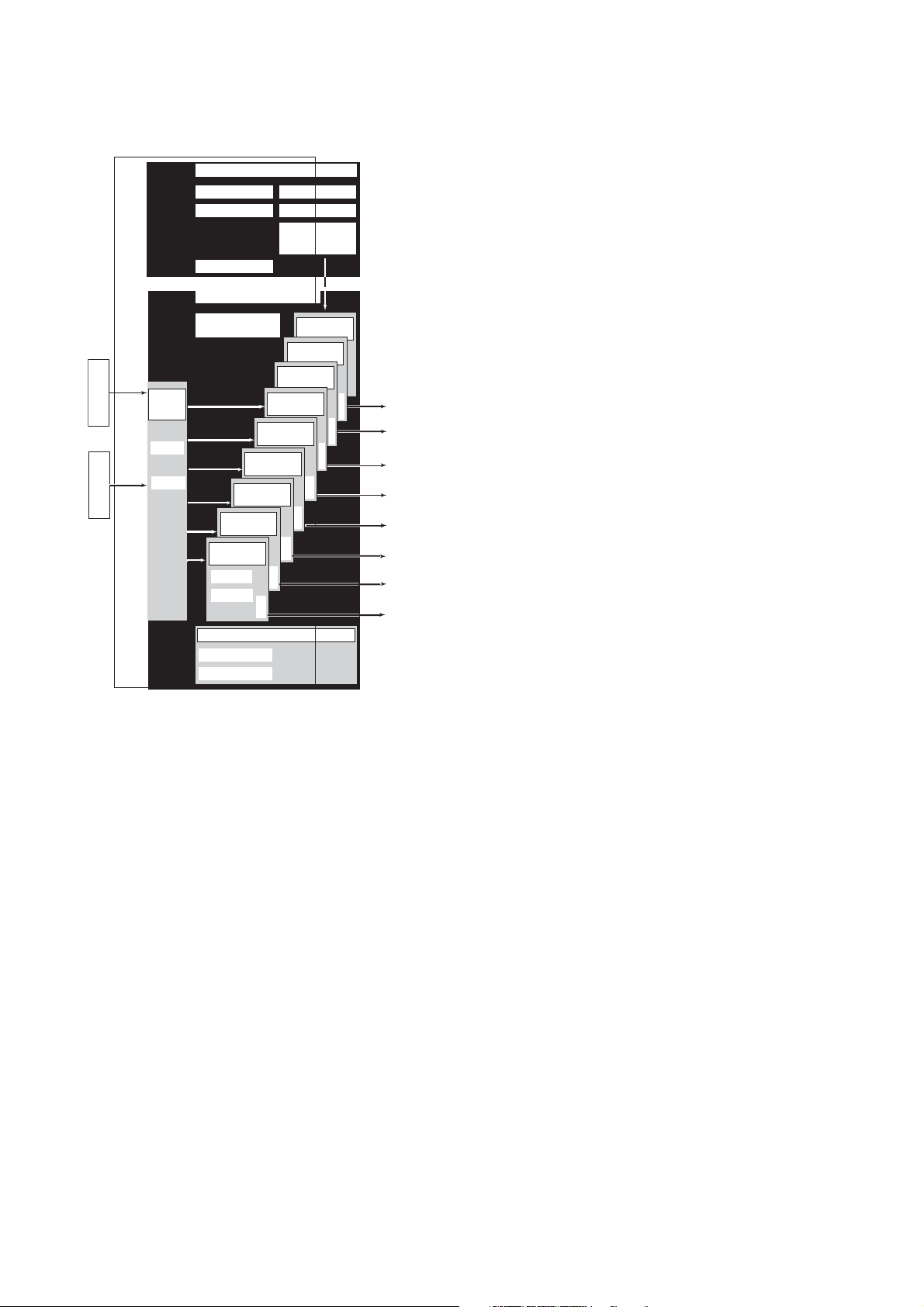
3. ABOUT FIELDBUS
3.3 Logical Structure of Each Block
Rotamass
Sensor
input
Sensor Coils
Sensor
input
Temp. sensor
Transducer
Block tag
Parameters
System/network management VFD
PD tag
Node address
Link master
Function block VFD
Software download
function
(optional)
block
AI4 function
AI3 function
block
AI2 function
block
AI1 function
block
Block tag
Parameters
Resource block
Block tag
Parameters
Communication parameters
VCR
Function block
execution schedule
PID function block
(optional)
IT 2 Integrator
block
IT 1 Integrator
block
AI6 function
block
AI5 function
block
block
OUT
OUT
OUT
OUT
OUT
OUT
OUT
OUT
F0301.EPS
3.4 Wiring System Configuration
The number of devices that can be connected to a
single bus and the cable length vary depending on
system design. When constructing systems, both
the basic and overall design must be carefully
considered to allow device performance to be fully
exhibited.
Output
Figure 3.1 Logical Structure of Each Block
Various parameters, the node address, and the
PD tag shown in Figure 3.1 must be set before
using the device. Refer to Chapter 4 for the
setting procedures.
IM 01R04B05-00E-E
2nd edition, June 2007
3-2
Page 19
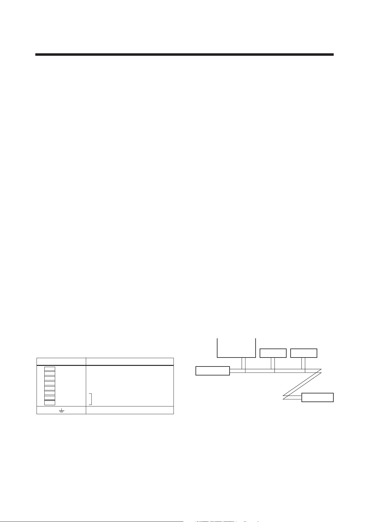
4. GETTING STARTED
S
S
4. GETTING STARTED
Fieldbus is fully dependent upon digital communication protocol and differs in operation from
conventional 4 to 20 mA transmission and the
HART communication protocol. It is recommended
that novice users use fieldbus devices in
accordance with the procedures described in this
section. The procedures assume that fieldbus
devices will be set up on a bench of an instrument
shop.
4.1 Connection of Devices
The following instruments are required for use
with Fieldbus devices:
• Power supply:
Fieldbus requires a dedicated power supply. It
is recommended that current capacity be well
over the total value of the maximum current
consumed by all devices (including the host).
Conventional DC current cannot be used as is.
• Host:
Used for accessing field devices. A dedicated
host (such as DCS) is used for an
instrumentation line while dedicated communication tools are used for experimental purposes.
For operation of the host, refer to the instruction
manual for each host. No details of the host are
explained in the rest of this manual.
• Cable:
Used for connecting devices. Refer to “Fieldbus
Technical Information” (TI 38K3A01-01E) for
details of instrumentation cabling. If the total
length of the cable is in a range of 2 to 3
meters for laboratory or other experimental use,
the following simplified cable (a twisted pair wire
with a cross section of 0.9 mm2 or more and
cycle period of within 5 cm (2 inches) may be
used). Termination processing depends on the
type of device being deployed. For the
ROTAMASS, clamp terminal are used. Some
hosts require a connector.
• Terminator:
Fieldbus requires two terminators. Refer to the
supplier for details of terminators that are
attached to the host.
• Field devices:
Connect your Fieldbus communication type
ROTAMASS RCCT3 to a fieldbus. Two or more
ROTAMASS RCCT3 and other field devices can
be connected. For the terminal assignment on
the ROTAMASS RCCT3, see Table 4.1.
Table 4.1 Terminal Connection for ROTAMASS RCCT3
Terminal Symbols Description
N.C.
N.C.
N.C.
N.C.
N.C.
N.C.
–
FF out
FF out
Fieldbus communication signal
+
Ground Terminal
F0401.EP
Refer to Yokogawa when making arrangements to
purchase the recommended equipment.
Connect the devices as shown in Figure 4.1.
Connect the terminators at both ends of the trunk,
with a minimum length of the spur laid for connection.
The polarity of signal and power must be maintained.
Fieldbus power
supply
Terminator
Figure 4.1 Device Connection
Rotamass
+
–
HOST
Terminator
F0402.EP
4-1
IM 01R04B05-00E-E
2nd edition, June 2007
Page 20

4. GETTING STARTED
T
T
Before using a Fieldbus configuration tool other
than the existing host, confirm it does not affect
the loop functionality in which all devices are
already installed in operation. Disconnect the
relevant control loop from the bus if necessary.
IMPORTAN
Connecting a Fieldbus configuration tool to a
loop with its existing host may cause communication data scrambles resulting in a functional
disorder or a system failure.
4.2 Host Setting
To activate Fieldbus, the following settings are
required for the host.
IMPORTAN
Do not turn off the main power supply and
fieldbus power supply immediately after setting.
When the parameters are saved to the
EEPROM, the redundant processing is executed
for the improvement of reliability. If the power is
turned off within 60 seconds after setting is
made, the modified parameters are not saved
and the settings may return to the original values.
0x00
Not used
0x0F
0x10
Bridge device
0x13
0x14
V(FUN)
V(FUN)+V(NUN)
Rotamass (0xF6)
Note 1: L M devic e : with bus con trol fu nc tion ( L ink Mas ter fu nc tion)
Note 2: B AS IC de vice: with out bus control function
Figure 4.2 Available Address Range
0xF7
0xF8
0xFB
0xFC
0xFF
LM device
Unused V(NUN)
BASIC device
Default address
P ortable devic e a ddress
F0403.E PS
4.3 Power-on of ROTAMASS and Bus
Turn on the power to the host, bus, and
ROTAMASS. If any segments do not light, or if a
current anomaly occurs, check the voltage of the
power supply for the ROTAMASS.
Using the host device display function, check that
the ROTAMASS is in operation on the bus. Unless
otherwise specified, the following settings are in
effect when shipped from the factory.
Table 4.2 Operation Parameters
Symbol Parameter Description and Settings
V (ST) Slot-Time
V (MID)
V (MRD)
V (FUN) First-Unpolled-Node
V (NUN)
IM 01R04B05-00E-E
2nd edition, June 2007
Minimum-Inter-PDUDelay
Maximum-ResponseDelay
Number-ofconsecutiveUnpolled-Nodes
Set 4 or greater value.
Set 4 or greater value.
Set so that V (MRD) 3 V
(ST) is 12 or greater
Indicate the address next
to the address range used
by the host. Set 0x15 or
greater.
Unused address range.
Rotamass addess is
factory set to 0xF6. Set
this address to be within
the range of BASIC device
in Figure 4.2.
T0401.EPS
PD tag: FT1004
Node address: 246 (hexadecimal F6)
Device ID: 594543000Dxxxxxxxx (xxxxxxxx = a
total of 8 alphanumeric characters)
If no ROTAMASS is detected, check the available
address range. If the node address and PD Tag
are not specified when ordering, default value is
factory set. If two or more ROTAMASS are
connected at a time with default value, only one
ROTAMASS will be detected from host as
ROTAMASS have the same initial address.
Connect the ROTAMASS one by one and set a
unique address for each.
4-2
Page 21

4. GETTING STARTED
4.4 Integration of DD
If the host supports DD (Device Description), the
DD of the ROTAMASS needs to be installed.
Check if host has the following directory under its
default DD directory.
594543000D
(594543 is the manufacturer number of
Yokogawa Electric Corporation, and 000D is the
ROTAMASS device number, respectively.)
If this directory is not found, the DD for the
ROTAMASS has not yet been installed. Create
this directory and copy the DD files (0m0n.ffo and
0m0n.sym to be supplied separately where m and
n are numerals) to it. If you do not have the DD
files for the ROTAMASS, you can download them
via Internet from
http://www.yokogawa.com/fld/FIELDBUS/fldfieldbus-01en.htm
Once the DD is installed in the directory, the
name and attribute of all parameters of the
ROTAMASS are displayed.
Off-line configuration is possible using the
capabilities file.
When using a capabilities (CFF) file, make sure
you use the right file for the intended device. The
ROTAMASS is offered in two types in terms of
capabilities:
(1) Without LC1 option: Featuring six AI function
blocks and two IT function blocks
(2) With LC1 option: A PID function block is
added
Using the wrong CFF file may result in an error
when downloading the configured data to the
device. Also, use the right DD files that
accommodate the revision of the intended device.
4.5 Reading the Parameters
To read ROTAMASS parameters, select the AI
block of the ROTAMASS from the host screen and
read the OUT parameter. The current flow rate is
displayed. Check that MODE_BLOCK of the
function block and resource block is set to AUTO.
4.6 Continuous Record of Values
If the host has a function of continuously recording
the indications, use this function to list the
indications (values). Depending on the host being
used, it may be necessary to set the schedule of
Publish (the function that transmits the indication
on a periodic basis).
4.7 Generation of Alarm
If the host is allowed to receive alarms, generation
of an alarm can be attempted from the
ROTAMASS. In this case, set the reception of
alarms on the host side. ROTAMASS’s VCR-7 is
factory-set for this purpose. For practical purposes,
all alarms are placed in a disabled status; for this
reason, it is recommended that you first use one
of these alarms on a trial basis. Set the value of
link object-3 (index 30002) as “0, 299, 0, 6, 0”.
Refer to section 5.6.1 Link Object for details.
Since the LO_PRI parameter (index 4029) of the AI
block is set to “0”, try setting this value to “3”.
Select the Write function from the host in operation, specify an index or variable name, and write
“3” to it.
The LO_LIM parameter (index 4030) of the AI
block determines the limit at which the lower
bound alarm for the process value is given. In
usual cases, a very small value is set to this limit.
Set smaller value than 100% value of XD_SCALE
(same unit). Since the flow rate is almost 0, a
lower bound alarm is raised. Check that the alarm
can be received at the host. When the alarm is
confirmed, transmission of the alarm is
suspended.
This chapter briefly explained how to connect the
ROTAMASS to a fieldbus and start using it. In
order to take full advantage of the performance and
functionality of the device, it is recommended that
it be read together with Chapter 5, where
describes how to use the ROTAMASS.
4-3
IM 01R04B05-00E-E
2nd edition, June 2007
Page 22

4. GETTING STARTED
Blank Page
IM 01R04B05-00E-E
2nd edition, June 2007
4-4
Page 23

5. CONFIGURATION
5. CONFIGURATION
This chapter contains information on how to adapt
the function and performance of the ROTAMASS to
suit specific applications. Because two or more
devices are connected to Fieldbus, settings
including the requirements of all devices need to
be determined. Practically, the following steps
must be taken.
(1) Network design
Determines the devices to be connected to
Fieldbus and checks the capacity of the power
supply.
(2) Network definition
Determines the PD tag and node addresses for
all devices.
(3) Definition of combining function blocks
Determines the method for combination
between each function block.
(4) Setting tags and addresses
Sets the PD Tag and node addresses one by
one for each device.
(5) Communication setting
Sets the link between communication
parameters and function blocks.
(6) Block setting
Sets the parameters for function blocks.
The following section describes each step of the
procedure in the order given. Using a dedicated
configuration tool allows the procedure to be
significantly simplified. This section describes the
procedure to be assigned for a host which has
relatively simple functions. Refer to Appendix 6
when the ROTAMASS is used as Link Master
(option).
consumed by all devices (including the host).
Conventional DC current cannot be used as
power supply.
• Terminator
Fieldbus requires two terminators. Refer to the
supplier for details of terminators that are
attached to the host.
• Field devices
Connect the field devices necessary for instrumentation. the ROTAMASS has passed the
interoperability test conducted by The Fieldbus
Foundation. In order to properly start Fieldbus,
it is recommended that the devices used satisfy
the requirements of the above test.
• Host
Used for accessing field devices. A minimum of
one device with bus control function is needed.
• Cable
Used for connecting devices. Refer to Fieldbus
Technical Information (TI 38K3A01-01E) for
details of instrumentation cabling. Provide a
cable sufficiently long to connect all devices.
For field branch cabling, use terminal boards or
a connection box as required.
First, check the capacity of the power supply. The
power supply capacity must be greater than the
sum of the maximum current consumed by all
devices to be connected to Fieldbus. For the
ROTAMASS, the maximum current (power supply
voltage: 9 to 32 VDC) is 15 mA. The cable must
have the spur in a minimum length with
terminators installed at both ends of the trunk.
5.2 Network Definition
5.1 Network Design
Select the devices to be connected to the
Fieldbus network. The following instruments are
necessary for operation of Fieldbus.
• Power supply
Fieldbus requires a dedicated power supply. It
is recommended that current capacity be well
over the total value of the maximum current
Before connection of devices with Fieldbus, define
the Fieldbus network. Allocate PD tags and node
addresses to all devices (excluding such passive
devices as terminators).
PD tags are the same as conventional tag
numbers assigned to devices. Up to 32
alphanumeric characters may be used for
definition of the PD tag for each device. Use
hyphens as delimiters as required.
5-1
IM 01R04B05-00E-E
2nd edition, June 2007
Page 24

5. CONFIGURATION
t
0x00
V
)
S
Node addresses are used to locate devices for
communication purposes. Since a PD tag is too
long for a data value, the host substitutes the
node addressed for PD tags in communication.
Node addresses can be set to numbers in a range
of decimal 16 to 247 (hexadecimal 10 to F7).
Assign devices having link master functionality
(i.e., LM devices) from the smallest address
number (0x10) in order, and other devices (i.e.,
basic devices) from the largest (0xF7). Assign an
address in the range for basic devices to a
ROTAMASS. Only when using a ROTAMASS
with the optional LM functionality as an LM device,
assign an address in the range for LM devices to
it. These address ranges are determined by the
following parameters.
Table 5.1 Parameters for Setting Address Range
Symbol
V (FUN) First-Unpolled-Node
V (NUN) Number-of-
Parameters Description
Indicates the address nex
to the address range used
for the host or other LM
device.
Unused address range
consecutiveUnpolled-Node
Any devices within an address range written as
“Unused” in Figure 5.1 cannot join the fieldbus.
Other address ranges are periodically scanned to
find any devices newly joining the fieldbus. Do
not widen the available address ranges
unnecessarily; the fieldbus communication
performance may be severely degraded.
Unused
0x0F
0x10
Bridge device
0x13
0x14
V(FUN)
(FUN)+V(NUN)
Figure 5.1 Available Range of Node Addresses
0xF7
0xF8
0xFB
0xFC
0xFF
LM devices
Unused V(NUN
Basic devices
Default addresses
Portable device addresses
F0501.EP
To ensure stable operation of Fieldbus, determine
the operation parameters and set them to the LM
devices. While the parameters in Table 5.2 are to
be set, the worst-case value of all the devices to
be connected to the same Fieldbus must be used.
Refer to the specification of each device for
details. Table 5.2 lists ROTAMASS specification
values.
Table 5.2 Operation Parameter Values of digitalYEWFLO
to be Set to LM Device
S
ymbol
V (S T) S lot-Time
V (MID) Minimum-Inter-P DU -
V (MRD) Maximum-R esponse-
Delay
Delay
P
arameters
D
escription a
Indica tes the time
necessa ry for immediate
reply of the device. Unit of
time is in octets (256 µs).
S et ma ximum s pecification
for all devices. F or a
Rotamass, set a value of 4
or greater.
Minimum value of
communication data
interva ls . Unit of time is in
octets (256 µs). S et the
maximum specifica tion for
all devices . For a
Rotamass, set a value of 4
or greater.
T he worst cas e time
ela ps ed until a reply is
recorded. T he unit is S lottime; s et the va lue s o th a t
V (MR D) 3V (ST) is the
maximum value of the
specifica tion for all devices .
For a Rotamass, value of
V(MRD)3V (ST) must be 12
or greater.
nd Setting
T0502.E PS
5.3 Function Block Link Definitions
Link the input/output parameters of function blocks
to each other as necessary. For a ROTAMASS,
the output parameters of six AI blocks (OUTs), two
integrator blocks and input/output parameters of
an optional PID block should be linked to parameters of different function blocks. Specifically, link
settings must be written to the link object in the
ROTAMASS For details, refer to Section 5.6,
“Block Setting.” It is also possible to read values
from the host at appropriate intervals instead of
linking the outputs of ROTAMASS’s function
blocks to other blocks.
s
IM 01R04B05-00E-E
2nd edition, June 2007
5-2
Page 25
5. CONFIGURATION
T0503.EPS
F
S
C
S
T
F0503.EPS
A
F0504.EPS
The linked blocks need to be executed synchronously with other blocks and the communication
schedule. In this case, change the schedule of
the ROTAMASS according to Table 5.3, in which
factory settings are shown in parentheses.
Table 5.3 Function Block Execution Schedule of
ROTAMASS
Index Parameters
269
MACROCYCLE_DURATION
(SM)
276
FB_START_ENTRY.1 Start time of the AI1 block
(SM)
277
FB_START_ENTRY.2 Start time of the PID block
(SM)
278 (SM)
FB_START_ENTRY.3 to
to
FB_START_ENTRY.14
289 (SM)
Setting (Factory Setting in
Parentheses)
Repetition period of control
or measurement, i.e.,
macrocycle; to be set as a
multiple of 1/32 ms (32000 =
1 second)
represented as the elapsed
time from the start of each
macrocycle; to be set as a
multiple of 1/32 ms (0 = 0
ms)
(optional) represented as
the elapsed time from the
start of each macrocycle; to
be set as a multiple of 1/32
ms (9600 = 300 ms)
Not set.
Macrocycle (Control Period)
FI103
FC100
FC200
FI200
unction
Block
chedule
ommu-
nication
chedule
Figure 5.3 Functionn Block Schedule and Communica-
FI100
OUT
BKCAL_IN
FI200
tion Schedule
IN
FIC100
OUT
CAS_IN
FIC200
IN
BKCAL_IN
Unscheduled
Communication
BKCAL_OUT
FC100
BKCAL_OU
Scheduled
Communication
When the control period (macrocycle) is set to
more than 4 seconds, set the following interval to
be more than 1% of the control period.
- Interval between “end of block execution” and
“start of sending CD from LAS”
- Interval between “end of block execution” and
“start of the next block execution”
A maximum of 30 ms is taken for execution of
each AI block. Arrange the communication
schedule for an AI block’s data that is to be
transferred to its downstream block in such a way
that it starts after a lapse of longer than 30 ms.
Figure 5.3 shows typical function block and
communication schedules for the loop shown in
Figure 5.2.
FIC 100
Rotamass
#1
FI100
Rotamass
#2
FI200
Figure 5.2 Example of Loop Connecting Function Blocks
of two ROTAMASS with other Devices
FIC 200
FC 100
F0502.E PS
5
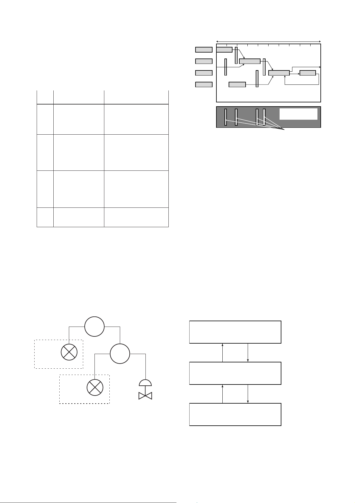
.4 Setting of Tags and Addresses
This section describes the steps in the procedure
to set the PD tags and node address in the
ROTAMASS. There are three states of Fieldbus
devices as shown in Figure 5.4, and if the state is
other than the lowest SM_OPERATIONAL state,
no function block is executed. Whenever you have
changed the PD tag or address of a ROTAMASS,
transfer its state to SM_OPERATIONAL.
UNINITIALIZED
(No tag nor address is set)
Tag clear Tag setting
INITIALIZED
(Only tag is set)
ddress clear
SM_OPERATIONAL
(Tag and address are retained, and
the function block can be executed.)
Address setting
Figure 5.4 Status Transition by Setting PD Tag and Node
Address
IM 01R04B05-00E-E
2nd edition, June 2007
5-3
Page 26

5. CONFIGURATION
In each ROTAMASS, the PD tag and node
address are set to “FT1004” and 246 (hexadecimal
F6), respectively, before shipment from the factory
unless otherwise specified. To change only the
node address, clear the address once and then
set a new node address. To set the PD tag, first
clear the node address and clear the PD tag, then
set the PD tag and node address again.Devices
whose node address was cleared will await at the
default address (randomly chosen from a range of
248 to 251, or from hexadecimal F8 to FB). At the
same time, it is necessary to specify the device ID
in order to correctly specify the device. The device
ID of the ROTAMASS is 594543000Dxxxxxxxx.
(The xxxxxxxx at the end of the above device ID is
a total of 8 alphanumeric characters.)
5.5 Communication Setting
To set the communication function, it is necessary
to change the database residing in SM (System
Management)-VFD.
5.5.1 VCR Setting
Set VCR (Virtual Communication Relationship),
which specifies the called party for communication
and resources. Each ROTAMASS has 33 VCRs
whose application can be changed, except for the
first VCR, which is used for management.
Each ROTAMASS has VCRs of four types:
Server (QUB) VCR
A server responds to requests from a host. This
communication needs data exchange. This type
of communication is called QUB (Queued Usertriggered Bidirectional) VCR.
Source (QUU) VCR
A source multicasts alarms or trends to other
devices. This type of communication is called
QUU (Queued User-triggered Unidirectional)
VCR.
Publisher (BNU) VCR
A publisher multicasts outputs of the AI blocks,
IT blocks, and PID block to other function
blocks. This type of communication is called
BNU (Buffered Network-triggered Unidirectional)
VCR.
Subscriber (BNU) VCR
A subscriber receives output of another function
block(s) by PID block.
Each VCR has the parameters listed in Table 5.4.
Parameters must be changed together for each
VCR because modification for each parameter
may cause a contradiction.
Table 5.4 VCR Static Entry
Sub-
ind
ex
1 Fas ArTypeAndRole
2 FasDllLocalAddr
3 F as DllC onfigured
4 F as DllS D AP
5 Fas DllMa xC onfirm
6 Fas DllMa xC onfirm
7 F as DllMa xDls duS ize
8 F as DllR e sidua l
9 F as DllT imeline ss C las s
10 F as DllP ublis herT ime
11 F as DllP ublis her
P
aramete
R emoteAddr
DelayO nConnect
DelayOnData
A cti vity S up por ted
WindowS ize
S ynchronizaingDlcep
r
D
escription
Indica tes the ty pe a nd role of
communication (VCR ). The
following 4 types a re use d
for the R ota mass .
0x32: Server (R esponds to
requests from host.)
0x44: Source (Transmits
alarm or trend.)
0x66: Publisher (S ends AI,
DI block output to
other blocks.)
0x76: S ubscriber (R eceives
output of other blocks
by P ID bloc k.)
S ets the loc a l a ddre s s to
specify a VCR in the
R ota ma s s. A range of 20 to
F 7 in hexadecimal.
S ets the node address of the
called party for
communication and the
addres s (DLS AP or D LCE P )
used to specify VCR in that
addres s. F or DLS AP or
DLC E P, a range of 20 to F7
in hexadecimal is us ed.
Addresses in Subindex 2
a nd 3 need to be s et to the
s a me c on tents of the V CR
as the called party (local and
remote are reversed).
S pecifies the quality of
communication. Usually, one
of the following types is set.
0x2B: S erver
0x01: Source (Alert)
0x03: Source (Trend)
0x91: P ublishe r/S ubs criber
To es tablish c onnection for
communication, a ma ximum
wait time for the calle d
party's response is set in
ms . T ypical value is 60
secounds (60000).
For reques t of data, a
maximum wait time for the
called party's response is
set in ms . Typica l value is
60 secounds (60000).
S pecifies maximum DL
S ervice Da ta unit Size
(DLS DU). S et 256 for Server
and Trend V C R , and 64 for
other VCR s.
S pecifies whether
connection is monitored. S et
T R U E (0xff) for S erve r. This
parameter is not us ed for
other communication.
Not used for the Rotamas s
Not used for the Rotamas s.
Not used for the Rotamas s.
T0504-1.E PS
IM 01R04B05-00E-E
2nd edition, June 2007
5-4
Page 27

5. CONFIGURATION
)
Sub-
ind
ex
12 F as DllS ubs cribe rTime
13 FasDllS ubscriber
14 FmsVfdId
1 5 F m s Ma xO u ts ta ndin g
1 6 F m s Ma xO u ts ta ndin g
17 FmsFeatures
P
aramete
WindowS ize
S ynchronizationDlcep
S erviceC a lling
S erviceC a lled
S upported
r
D
escription
Not used for the Rotamass.
Not used for the Rotamass.
S ets VF D for the R ota mas s
to be u s e d.
0x1: Sys tem/network
mana geme nt VF D
0x1234: Function block
VFD
S et 0 to S e rver. It is not
us ed for other a pplica tions .
S et 1 to S e rver. It is not
us ed for other a pplica tions .
Indica tes the type of s e rv ic es
in the a pplica tion layer. In the
R ota mass, it is a utomatically
s e t a cco rding to s pec ific
applications.
T0504-2.E PS
These 33 VCRs are factory-set as shown in Table 5.5.
Table 5.5 VCR List
I
nd
ex
)
VCR
N
umber
5
7
9 to 33
R emote Address=0x111)
Alert Source (LocalAddr = 0x07,
R emote Address=0x110)
Not set
(SM
293 For system management (Fixed)1
294 S erver (L ocalAddr = 0xF 3)2
295 S erver (L ocalAddr = 0xF 4)3
296 S erver (L ocalAddr = 0xF 7)4
297 Trend S ource (LocalAddr = 0x07,
298 Publisher (LocalAddr = 0x20)6
299
300 S erver (LocalAddr = 0xF 9)8
301 to 325
F
actory Setting
T0505.E PS
5.5.2 Function Block Execution Control
According to the instructions given in Section 5.3,
set the execution cycle of the function blocks and
schedule of execution.
5.6 Block Setting
Set the parameter for function block VFD.
5.6.1 Link Objects
A link object combines the data voluntarily sent by
the function block with VCR. Each ROTAMASS
has 40 link objects. A single link object specifies
one combination. Each link object has the param-
eters listed in Table 5.6. Parameters must be
changed together for each VCR because the
modifications made to each parameter may cause
inconsistent operation.
Table 5.6 Link Object Parameters
Sub-
ind
ex
1LocalIndex
2VcrNumber
3 R emoteIndex
4 S erviceOperation
5 S taleC ountLimit
P
arameters
D
escription
S ets the index of func tion
block parame ters to be
combined; set “0” for Trend
and Alert.
S ets the index of V C R to
be combined. If set to “0”,
this link object is not used.
Not us ed in the R ota ma ss .
S et to “0 ”.
S et one of the following.
S et only one ea ch for link
object for Alert or Trend.
0: Undefined
2: P ublisher
3: Subscriber
6: Alert
7: Trend
S et the ma ximum number
of consecutive stale input
values which may be
received before the input
status is set to BAD. To
avoid the unneces s ary
mode tra ns itio n c a used
when the da ta is not
correctly received by
subscriber, set this
parameter to “2” or more.
Link objects are not factory-set. Set link objects as
shown in Table 5.7.
Table 5.7 Settings of Link Objects (example)
Index Link Object #
30000
30001 2
30002 3
30003 to 30039
1
Settings(example
AI. OUT VCR#6
Trend VCR#5
Alert VCR#7
No used4 to 40
5.6.2 Trend Objects
It is possible to make settings so that a function
block automatically transmits the trend. For this,
each ROTAMASS has ten trend objects: eight for
trends of analog parameters and two for discrete
parameters. For each trend object, specify a
single parameter, the trend of which is to be
transmitted.
Each trend object has the parameters listed in
Table 5.8. For the first four parameters, setting is
mandatory. Before writing parameter settings to a
trend object, parameter WRITE_LOCK of the
resource block must be modified to unlock the
write-lock.
5-5
IM 01R04B05-00E-E
2nd edition, June 2007
T0506.E PS
Page 28
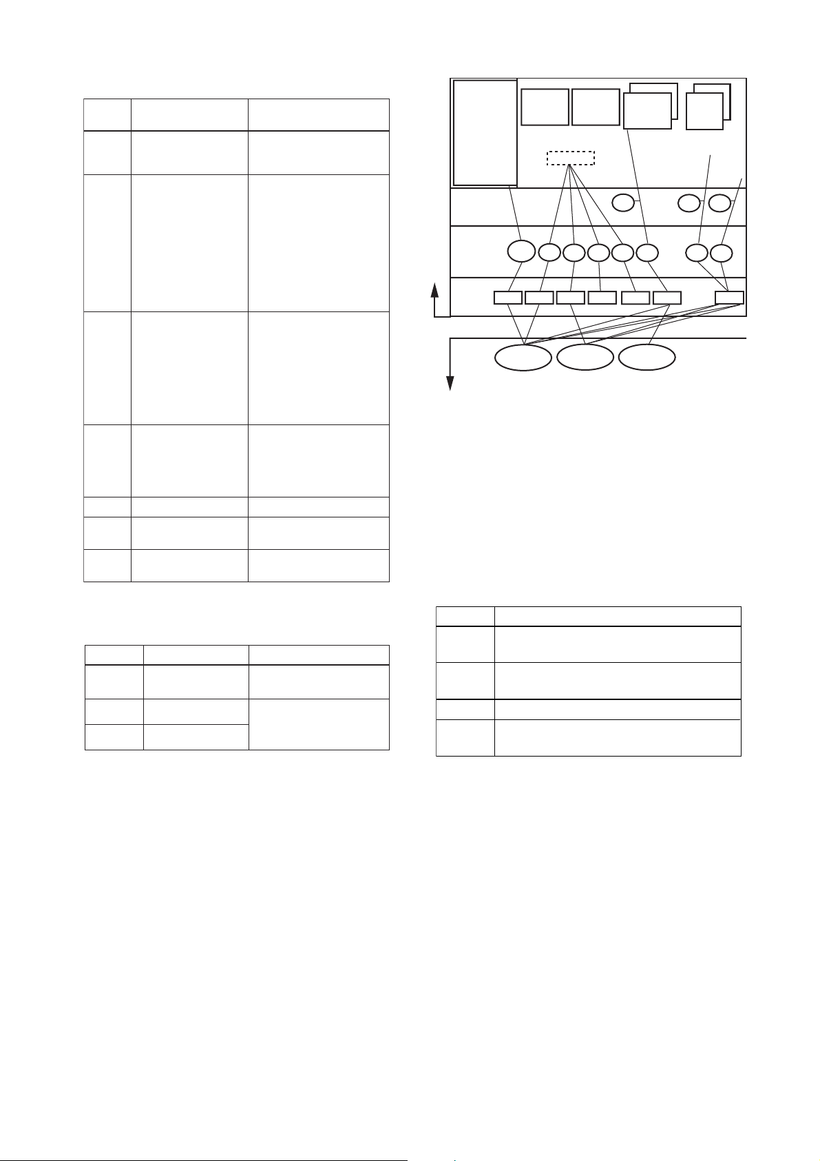
5. CONFIGURATION
S
r
r
Table 5.8 Parameters for Trend Objects
Sub-
ind
ex
1Block Index
2 Parameter Relative
3 S ample Type
4 Sample Interval
5 Las t U pdate
6 to 21 List of S tatus
21 to 37 List of S amples
Index
P
arameters
D
escription
S ets the leading index of
the fu nc tion bloc k tha t
ta ke s a trend.
S ets the index of pa rameters
ta king a trend by a value
re la tive to the beginnin g of the
function block. In the
R ota ma s s, the fo llowing thre e
types of trends are pos sible.
7: P V
8: OUT
19: F IE LD_VAL
Specifies how trends are
taken. C hoose one of the
following 2 types :
1: Sampled upon
execution of a function
block.
2: The average value is
sampled.
S pecifies sampling
interva ls in units of 1/32
ms . S et the integ er
multiple of the function
block execution cycle.
T he la s t sampling time.
Status part of a sampled
parameter.
Data part of a sampled
parameter.
Ten trend objects are not factory-set.
Table 5.9 Trend Objects
Index Parameter Factory Setting
32000 to
32007
32008
32009
TREND_FLT.1 to
TREND_FLT.8
TREND_DIS.1
TREND_DIS.2
Not set.
Not set (these parameters
are used with a DI block o
optional PID block).
T0508.E PS
T0509.EP
System
Mana gement
Information
Base (SMIB)
Network
Mana gement
Information
Base (NMIB)
Link object
VCR
Resource
block
#1
#2
Transducer
FBOD
#3
block
#4 #8
AI2 OUT
AI1 OUT
#1 #3
#6
DI2
OUT
DI1
OUT
Alert
#7
Trend
#2
#5
ROTAMASS
DLS AP
DLCEP
Fieldbus Cable
Figure 5.5 Examle of Default Configuration
0xF8 0xF3 0xF4 0xF7
Host 1 Hos t 2
0xF9
Device
0x20
0x07
F0505.E PS
5.6.3 View Objects
View objects are used to group parameters. This
reduces the load of data transactions. Each
ROTAMASS supports four view objects for each of
the resource block, transducer block, six AI
blocks, two IT blocks, and PID block (optional).
Each view object contains a group of the parameters listed in Tables 5.11 to 5.14.
Table 5.10 Purpose of Each View Object
Description
VIEW_1
VIEW_2
VIEW_3
VIEW_4
Set of dynamic parameters required by operato
for plant operation. (PV, SV, OUT, Mode etc.)
Set of static parameters which need to be
shown to plant operator at once. (Range etc.)
Set of all the dynamic parameters.
Set of static parameters for configuration or
maintenance.
IM 01R04B05-00E-E
2nd edition, June 2007
5-6
Page 29

5. CONFIGURATION
Table 5.11 View Objects for Resource Block
Relative
Parameter Mnemonic
Index
1 ST_REV 2 2 2 2
2 TAG_DESC
3 STRATEGY 2
4 ALERT_KEY 1
5 MODE_BLK 4 4
6 BLOCK_ERR 2 2
7 RS_STATE 1 1
8 TEST_RW
9 DD_RESOURCE
10 MANUFAC_ID 4
11 DEV_TYPE 2
12 DEV_REV 1
13 DD_REV 1
14 GRANT_DENY 2
15 HARD_TYPES 2
16 RESTART
17 FEATURES 2
18 FEATURE_SEL 2
19 CYCLE_TYPE 1
20 CYCLE_SEL 1
21 MIN_CYCLE_T 4
22 MEMORY_SIZE 2
23 NV_CYCLE_T 4
24 FREE_SPACE 4
25 FREE_TIME 4 4
26 SHED_RCAS 4
27 SHED_ROUT 4
28 FAIL_SAFE 1 1
29 SET_FSAFE
30 CLR_FSAFE
31 MAX_NOTIFY 4
32 LIM_NOTIFY 4
33 CONFIRM_TIME 4
34 WRITE_LOCK 1
35 UPDATE_EVT
36 BLOCK_ALM
37 ALARM_SUM 8 8
38 ACK_OPTION 2
39 WRITE_PRI 1
40 WRITE_ALM
41 ITK_VER
42 SOFT_REV
43 SOFT_DESC
44 SIM_ENABLE_MSG
45 DEVICE_STATUS_1 4
46 DEVICE_STATUS_2 4
47 DEVICE_STATUS_3 4
48 DEVICE_STATUS_4 4
49 DEVICE_STATUS_5 4
50 DEVICE_STATUS_6 4
51 DEVICE_STATUS_7 4
52 DEVICE_STATUS_8 4
Total bytes 22 32 54 31
VIEW
1
VIEW
2
VIEW
3
VIEW
4
T0511.EPS
5-7
IM 01R04B05-00E-E
2nd edition, June 2007
Page 30

5. CONFIGURATION
Table 5.12 View Objects for Transducer Block
PARAMETERINDEX
Index Parameter VIEW_1 VIEW_2
1ST_REV 222222222222
2 TAG_DESC
3 STRATEGY 2
4 ALERT_KEY 1
5 MODE_BLK 4 4
6 BLOCK_ERR 2 2
7 UPDATE_EVT
8 BLOCK_ALM
9 TRANSDUCER_DIRECTORY
10 TRANSDUCER_TYPE 2 2 2 2
11 XD_ERROR 1 1 1
12 COLLECTION_DIRECTORY
13 CAL_POINT_HI 4 4
14 CAL_POINT_LO 4 4
15 CAL_MIN_SPAN 4
16 CAL_UNIT 2
17 SENSOR_TYPE 2
18 SENSOR_RANGE 11
19 SENSOR_SN 32
20 SENSOR_CAL_METHOD 1
21 SENSOR_CAL_LOC 32
22 SENSOR_CAL_DATE 7
23 SENSOR_CAL_WHO 32
24 LIN_TYPE 1
25 MASS_FLOW_VALUE 5 5
26 MASS_FLOW_VALUE_RANGE 11
27 MASS_FLOW_VALUE_FTIME 4
28 MASS_FLOW_LOWCUT 4
29 VOLUME_FLOW _VALUE 5 5
30 VOLUME_FLOW_VALUE_RANGE 11
31 VOLUME_FLOW_VALUE_FTIME 4
32 VOLUME_FLOW_LOWCUT 4
33 DENSITY_VALUE 5 5
34 DENSITY_VALUE_RANGE 11
35 DENSITY_VALUE_FTIME 4
36 DENSITY_LOWCUT 4
37 TEMPERATURE _VALUE 5 5
38 TEMPERATURE _VALUE_RANGE 11
39 TEMPERATURE_VALUE_FTIME 4
40 CONCENTR_MEAS_VALUE 5 5
41 CONCENTR_MEAS_VALUE_RANGE 11
42 CONCENTR_MEAS_VALUE_FTIME 4
43 CONCENTR_MEAS_LOWCUT 4
44 NET_FLOW_VALUE 5 5
45 NET_FLOW_VALUE_RANGE 11
46 NET_FLOW_VALUE_FTIME 4
47 NET_FLOW_LOWCUT 4
48 DISP_SELECT_1 1
49 DISP_SELECT_2 1
50 DISP_SELECT_3 1
51 DISP_SELECT_4 1
52 DISP_DECIMAL_MASS_FLOW 1
53 DISP_DECIMAL_VOLUME_FLOW 1
54 DISP_DECIMAL_DENSITY 1
55 DISP_DECIMAL_TEMPERATURE 1
56 DISP_DECIMAL_CONCENTR_MEAS 1
57 DISP_DECIMAL_NET_FLOW 1
58 DISP_DECIMAL_IT1 1
59 DISP_DECIMAL_IT2 1
60 DISP_IT1_UNITS_INDEX 2
61 DISP_IT2_UNITS_INDEX 2
62 DISP_CONTRAST 1
63 DISP_PERIOD 1
64 DISP_LANGUAGE 1
65 FLOW_DIRECTION 1
66 BI_DIRECTION 1
67 AUTO_ZERO_TIME 1
68 AUTO_ZERO_EXE 1
69 AUTOZERO_VALUE 4
70 AUTOZERO_FLUCTUATION 4
71 AZ_INIT_MASS_FLOW 4
72 AZ_INIT_DENSITY 4
73 AZ_INIT_TEMP 4
74 MASS_FLOW_FIX_VAL_SEL 1
75 MASS_FLOW_FIXED_VALUE 4
76 DENSITY_FIX_VAL_SEL 1
77 DENSITY_FIXED_VALUE 4
78 TEMP_FIX_VAL_SELECT 1
79 TEMP_FIXED_VALUE 4
80 TEMP_GAIN 4
81 SENSOR_MODEL 1
82 SK20 4
83 SKT 4
84 RV 4
85 QNOM 4
86 KD 4
87 FL20 4
88 FTC1 4
89 FTCK 4
VIEW_3_1st VIE W_3_2st VIEW_3_3st VIE W_4 1st VIE W_4 2st VIE W_4 3st VIE W_4 4st VIEW_4 5st VIEW_4 6st VIEW_4 7st
VIEW_2VIEW_1
T0512_1.EPS
* Continued on next page
IM 01R04B05-00E-E
2nd edition, June 2007
5-8
Page 31

5. CONFIGURATION
PARAMETERINDEX
Index Parameter VIEW_1 VIEW_2
90 SKP 4
91 FPC 4
92 PRESSURE 4
93 PRESSURE_UNIT 2
94 SLUG_ALARM_SELECT 1
95 DRIVE_GAIN 4
96 SLUG_CRITERIA 4
97 SLUG_DURATION 4
98 AFTER_SLUG 1
99 DRIVE_GAIN_DAMPING 4
100 EMPTY_ PIPE_ALM_SEL 1
101 EMPTY_PIPE_CRIT 4
102 AFTER_EMPTY_PIPE 1
103 CORROSION_ALM_SEL 1
104 CORROSION_CRIT 4
105 CORROSION_DAMP 4
106 FLUID_MAX_TEMP 4
107 SELF_TEST 1
108 INITIALIZE_EEPROM 2
109 ERR_STATUS 4
110 ALM_STATUS 4
111 WARNG_STATUS 4
112 HIST_ORD 20
113 HIST_ABS_ERR 4
114 HIST_ABS_ALM 4
115 HIST_ABS_WARNG 4
116 CLEAR_HIST 1
117 ALARM_PERFORM 2
118 ALARM_SUM 8
119 TEST_1 1
120 TEST_2 1
121 TEST_3 1
122 TEST_4 4
123 TEST_5 4
124 TEST_6 4
125 TEST_7 4
126 TEST_8 4
127 TEST_9 4
128 TEST_10 4
129 TEST_11 4
130 TEST_12 1
131 TEST_13 4
132 TEST_14 4
133 TEST_15 4
134 TEST_16 4
135 TEST_17 4
136 TEST_18 1
137 TEST_19 4
138 TEST_20 4
139 TEST_21 1
140 TEST_22 1
141 TEST_23 4
142 TEST_24 1
143 TEST_25 4
144 TEST_26 4
145 TEST_27 22
146 TEST_28 1
147 TEST_29 1
148 TEST_30 1
149 TEST_31 1
150 TEST_32 2
151 TEST_33 4
152 TEST_34 1
153 TEST_35 1
154 TEST_36 1
155 TEST_37 2
156 TEST_38 1
157 TEST_39 1
158 TEST_40 4
159 TEST_41 4
160 TEST_42 4
161 TEST_43 4
162 TEST_44 4
163 TEST_45 4
164 TEST_46 1
165 TEST_47 4
166 TEST_48 1
167 TEST_49 32
168 TEST_50 32
169 TEST_51 32
170 TEST_52 1
171 TEST_53 1
172 TEST_54
173 TEST_55
174 TEST_56
175 TEST_57
176 TEST_58 2
177 TEST_59 2
178 TEST_60
179 TEST_61 1
41 12 61 88 38 67 75 74 82 91 87 100
VIEW_3_1st VIEW_3_2s t VIEW_3_3st VIEW_4 1st VIEW_4 2s t VIEW_4 3st VIEW_4 4st VIEW_4 5st VIEW_4 6st VIEW_4 7stVIEW_2VIEW_1
T0512-2.EPS
5-9
IM 01R04B05-00E-E
2nd edition, June 2007
Page 32

5. CONFIGURATION
Table 5.13 View Objects for the AI Function Blocks
R
elati
nd
I
ve
P
aramete
ex
r
M
nem
VIEW1VIEW2VIEW
oni
c
VIEW
3
4
1 ST_REV 2 2 2 2
2 TAG_DESC
3 STRATEGY 2
4 ALERT_KEY 1
5 MODE_BLK 4 4
6 BLOCK_ERR 2 2
7 PV 5 5
8 OUT 5 5
9 SIMULATE
10 XD_SCALE 11
11 OUT_SCALE 11
12 GRANT_DENY 2
13 IO_OPTS 2
14 STATUS_OPTS 2
15 CHANNEL 2
16 L_TYPE 1
17 LOW_CUT 4
18 PV_FTIME 4
19 FIELD_VAL 5 5
20 UPDATE_EVP
21 BLOCK_ALM
22 ALARM_SUM 8 8
23 ACK_OPTION 2
24 ALARM_HYS 4
25 HI_HI_PRI 1
26 HI_HI_LIM 4
27 HI_PRI 1
28 HI_LIM 4
29 LO_PRI 1
30 LO_LIM 4
31 LO_LO_PRI 1
32 LO_LO_LIM 4
33 HI_HI_ALM
34 HI_ALM
35 LO_ALM
36 LO_LO_ALM
Total bytes 31 26 31 46
T0513.EPS
IM 01R04B05-00E-E
2nd edition, June 2007
5-10
Page 33

5. CONFIGURATION
S
T0515-2.EPS
S
Table 5.14 View Objects for PID Function Block
(Optional)
Relative
Index
Parameter Mnemonic
VIEW
1
VIEW
2
VIEW
3
VIEW
4
1 ST_REV 2 2 2 2
2 TAG_DESC
3 STRATEGY 2
4 ALERT_KEY 1
5 MODE_BLK 4 4
6 BLOCK_ERR 2 2
7 PV 5 5
8 SP 5 5
9 OUT 5 5
10 PV_SCALE 11
11 OUT_SCALE 11
12 GRANT_DENY 2
13 CONTROL_OPTS 2
14 STATUS_OPTS 2
15 IN 5
16 PV_FTIME 4
17 BYPASS 1
18 CAS_IN 5 5
19 SP_RATE_DN 4
20 SP_RATE_UP 4
21 SP_HI_LIM 4
22 SP_LO_LIM 4
23 GAIN 4
24 RESET 4
25 BAL_TIME 4
26 RATE 4
27 BKCAL_IN 5
28 OUT_HI_LIM 4
29 OUT_LO_LIM 4
30 BKCAL_HYS 4
31 BKCAL_OUT 5
32 RCAS_IN 5
33 ROUT_IN 5
34 SHED_OPT 1
35 RCAS_OUT 5
36 ROUT_OUT 5
37 TRK_SCALE 11
38 TRK_IN_D 2 2
39 TRK_VAL 5 5
40 FF_VAL 5
T0515-1.EP
Relative
Index
Table 5.15 Indexes to View Objects for Each Block
Resource block
Transducer block
AI1 block
AI2 block
AI3 block
AI4 block
AI5 block
AI6 block
IT1 block
IT2 block
PID block (optional)
Parameter Mnemonic
41 FF_SCALE 11
42 FF_GAIN 4
43 UPDATE_EVT
44 BLOCK_ALM
45 ALARM_SUM 8 8
46 ACK_OPTION 2
47 ALARM_HYS 4
48 HI_HI_PRI 1
49 HI_HI_LIM 4
50 HI_PRI 1
51 HI_LIM 4
52 LO_PRI 1
53 LO_LIM 4
54 LO_LO_PRI 1
55 LO_LO_LIM 4
56 DV_HI_PRI 1
57 DV_HI_LIM 4
58 DV_LO_PRI 1
59 DV_LO_LIM 4
60 HI_HI_ALM
61 HI_ALM
62 LO_ALM
63 LO_LO_ALM
64 DV_HI_ALM
65 DV_LO_ALM
Total bytes 43 43 83 104
B
lo
ck
VIEW1VIEW2VIEW3VIEW
40100 40101
40200
40400
40410
40420
40430
40440
40450
40600
40610
40800
VIEW
1
40201
40401
40411
40421
40431
40441
40451
40601
40611
40801
5-11
VIEW
VIEW
2
VIEW
3
4
4
40102
40103
4020340202
40402
40412
40422
40432
40442
40452
40602
40612
40802
IM 01R04B05-00E-E
2nd edition, June 2007
40403
40413
40423
40433
40443
40453
40603
40613
40803
T0516.EP
Page 34

5. CONFIGURATION
5.6.4 AI Function Block Parameters
Parameters of the six AI function blocks can be
read and written from the host. For a list of block
parameters in each ROTAMASS, refer to Appendix
1, “List of Parameters for Each Block of
ROTAMASS.” The following describes important
parameters and how to set them. For a model
with an option adding a PID function block and LM
functionality, see Appendixes 5 and 6.
MODE_BLK:
Indicates the three types of function block
modes; Out_Of_Service, Manual, and Auto. In
Out_Of_Service mode, the AI block does not
operate. The Manual mode does not allow
values to be updated. The Auto mode causes
the measured value to be updated. Under
normal circumstances, set the Auto mode to
take effect. The Auto mode is the factory
default.
CHANNEL:
This is the parameter of the transducer block to
be input to the AI block. AI1 block is assigned
mass flow rate. AI2 block is assigned volume
flow rate. AI3 block is asigned density. AI4
block is asigned temperature. AI5 is assigned
concentration measurement. AI 6 is assigned
net flow rate. Do not change this setting.
XD_SCALE:
Scale of input from the transducer block.
Changing the unit (can be set only in mass flow
rate) also causes the unit within the transducer
block to be automatically changed. (The unit is
automatically changed according to the unit
selected by AI 1, 2, 3, 4, 5, 6.
AI5.XD_SCALE.UNIT_INDEX depend on
customer’s spec.) Units which can be set by
XD_SCALE are shown Table 5.17.
.
Table 5.16 Available Units
B
lo
I
tem
XD_S C ALE
ck
AI1
(channel 1:
PV)
AI2
(channel 2:
SV)
AI3
(channel3:
TV)
AI4
(channel 4:
QV)
AI5
(channel 5:
5V)
AI6
(channel 6:
6V)
Mass flow
Volume
flow
Density
Temperature
Concenta tion
acc. to
cus tome r's
spec.
Net flow
A
vailable
U
nits
1318:g/sec
1319:g/min
1320:g/h
1322:kg/s
1323:kg/min
1324:kg/h
1327:t/min
1328:t/h
1330:lb/s
1331:lb/min
1332:lb/h
1511:cucm/s
1512:cucm/min
1513:cucm/h
1351:l/s
1352:l/min
1353:l/h
1347:cum/s
1348:cum/min
1349:cum/h
1362:gal/s
1363:gal/min
1364:gal/h
1356:cuft/s
135 7:cuft/min
1358:cuft/h
1371:bbl/s
1372:bbl/min
1373:bbl/h
136 7:Impgal/s
136 8:Impgal/min
136 9:Impgal/h
1104:g/ml
1103:kg/l
1097:kg/cum
110 8:lb/gal
1107:lb/cuft
1000:Kelvin
1001:degC
1002:degF
1426:DegBrix(˚B rix)
1111:H-B aume
1112:L-Baume
1113:degAP I
1343:WT-% s ol
65520:WT-%
1344:Vol-% sol
65521:Vol-%
1318:g/sec
1319:g/min
1320:g/h
1322:kg/s
1323:kg/min
1324:kg/h
1327:t/min
1328:t/h
1330:lb/s
1331:lb/min
1332:lb/h
T0517.E PS
IM 01R04B05-00E-E
2nd edition, June 2007
Note: With the same setting, some units are represented
differently between the FOUNDATION Fieldbus communication type and the HART communication type of a
ROTAMASS. Each unit enclosed in brackets above
shows the unit for the HART communication type of
ROTAMASS corresponding to the preceding unit (for
the Foundation Fieldbus communication type).
5-12
Page 35

OUT_SCALE:
Sets the range of output (from 0% to 100%).
Available units for OUT_SCALE are the Table
5.17 units for XD_SCALE.
L_TYPE:
Specifies the operation function of the AI
blocks. The factory default is “Direct”, so the
input delivered to CHANNEL is directly reflected
on OUT. If set to “Indirect”, scaling by
XD_SCALE and OUT_SCALE is carried out and
is reflected on OUT. “Indirect SQRT” is not
used for ROTAMASS.
PV_FTIME:
Sets the time constant of the damping function
within the AI blocks (primary delay) in seconds.
Alarm Priority:
Indicates the priority of the process alarm. If a
value of 3 or greater is set, an alarm is transmitted. The factory default is 0. Four types of
alarm can be set: HI_PRI, HI_HI_PRI, LO_PRI,
and LO_LO_PRI.
5. CONFIGURATION
Alarm Threshold:
Sets the threshold at which a process alarm is
generated. The factory default setting is a value
that does not generate an alarm. Four types of
alarm can be set: HI_LIM, HI_HI_LIM, LO_LIM,
and LO_LO_LIM.
5-13
IM 01R04B05-00E-E
2nd edition, June 2007
Page 36

5. CONFIGURATION
5.6.5 Transducer Block Parameters
The transducer block sets function specific to the
flow rate measurement of the ROTAMASS. For a
list of block parameters in each ROTAMASS, refer
to Appendix 1, “List of Parameters for Each Block
of ROTAMASS.” The following describes important
parameters and how to set them.
Parameters for Zero Tuning
1) AUTO_ZERO_TIME
(Relative Index 67)
Defines the duration of the auto zero
function as follows:
1 = 3 Minute
2 = 30 Seconds
2) AUTO_ZERO_EXE
(Relative Index 68)
Starts the auto zero function to be performed as follows:
1 = Not Execute
2 = Execute
Parameters for Primary Variable
3) MASS_FLOW_VALUE_FTIME
(Relative Index 27)
Defines the damping time constant for the
mass flow rate to be input to the flow rate
calculation.
Setting range: 0.1 to 200 (seconds)
Default: 3 (seconds)
4) MASS_FLOW_LOWCUT
(Relative Index 28)
Sets the low cutoff mass flow rate level.
Setting range: Minimum flow rate 0 to 10%
of MASS_FLOW_VALUE_RANGE.
EU_100. The default value is 0 %.
Unit: As selected in
AI1.XD_SCALE.UNITS_INDEX
Parameters for Secondary Variable
5) VOLUME_FLOW_VALUE_FTIME
(Relative Index 31)
Defines the damping time constant for the
volume flow rate to be input to the flow
rate calculation.
6) VOLUME_FLOW_LOWCUT
(Relative Index 32)
Sets the low cutoff volume flow rate level.
Setting range: Minimum flow rate 0 to 10%
of VOLUME_FLOW_VALUE_RANGE.
EU_100. The default value is 0 %.
Unit: As selected in
AI2.XD_SCALE.UNITS_INDEX
Parameters for Tertiary Variable
7) DENSITY_VALUE_FTIME
(Relative Index 35)
Defines the damping time constant for the
density to be input to the density calculation.
Setting range: 0.1 to 200 (seconds)
Default: 15 (seconds)
8) DENSITY_LOWCUT
(Relative Index 36)
Sets the low cutoff density level.
Setting range: Minimum value 0 to 10% of
DENSITY_VALUE_RANGE.EU_100.
The default value is 0 %.
Unit: As selected in
AI3.XD_SCALE.UNITS_INDEX
Parameters for Quaternary Variable
9) TEMPERATUR_VALUE_FTIME
(Relative Index 39)
Defines the damping time constant for the
temperature to be input to the temperature
calculation.
Setting range: 0.1 to 200 (seconds)
Default: 15 (seconds)
Parameters for flow direction
10) FLOW_DIRECTION
(Relative Index 65)
Defines the direction of the flow and
determines the sign of the calculated flow
rate values.
Setting range: Forward; Reverse
Default: Forward
Setting range: 0.1 to 200 (seconds)
Default: 3 (seconds)
IM 01R04B05-00E-E
2nd edition, June 2007
5-14
Page 37

5. CONFIGURATION
11) BI_DIRECTION
(Relative Index 66)
Enables the ROTAMASS to measure the
flow in bi- or uni-direction mode. The sign
of the calculated flow rate values depends
on the flow direction.
Setting range: Bi-Direction; Uni-Direction
Default: Bi-Direction
Parameters for local Display
12) DISP_SELECT_1
(Relative Index 48)
Selects the data to be displayed on the
first line of the LCD indicator, as follows
(Default : Massflow) :
1 = AI1 OUT = Massflow:
Actual mass flow rate
2 = AI2 OUT = Volumeflow:
Actual volume flow rate
3 = AI3 OUT = Density:
Actual density value
4 = AI4 OUT = Temperature:
Actual temperature value
5 = AI5 OUT = Conc Meas: Actual
calculated concentration value
15) DISP_SELECT_4
(Relative Index 51)
Selects the data to be displayed on the
fourth line of the LCD indicator, as follows:
see DISP_SELECT_1
255 : None
16) DISP_DECIMAL_MASS_FLOW
(Relative Index 52)
Selects the format of the mass flow value
to be displayed on the LCD indicator, as
follows:
1 = xxxxxxx: No decimal point (7 digits)
2 = xxxxx.X: 1 digit after DP resolution
3 = xxxx.XX: 2 digit after DP resolution
4 = xxx.XXX: 3 digit after DP resolution
5 = xx.XXXX: 4 digit after DP resolution
6 = x.XXXXX: 5 digit after DP resolution
17) DISP_DECIMAL_VOLUME_FLOW
(Relative Index 53)
Selects the format of the volume flow
value to be displayed on the LCD indicator, as follows:
see DISP_DECIMAL_MASS_FLOW
6 = AI6 OUT = Netflow:
Actual net flow rate
7 = IT1 OUT = IT1: Integrator 1 totalized value
8 = IT2 OUT = IT2: Integrator 2 totalized value
13) DISP_SELECT_2
(Relative Index 49)
Selects the data to be displayed on the
second line of the LCD indicator, as
follows:
see DISP_SELECT_1
255 : None
14) DISP_SELECT_3
(Relative Index 50)
Selects the data to be displayed on the
third line of the LCD indicator, as follows:
see DISP_SELECT_1
255 : None
18) DISP_DECIMAL_DENSITY
(Relative Index 54)
Selects the format of the density value to
be displayed on the LCD indicator, as
follows:
see DISP_DECIMAL_MASS_FLOW
19) DISP_DECIMAL_TEMPERATURE
(Relative Index 55)
Selects the format of the temperature
value to be displayed on the LCD indicator, as follows:
see DISP_DECIMAL_MASS_FLOW
5-15
IM 01R04B05-00E-E
2nd edition, June 2007
Page 38

5. CONFIGURATION
20) DISP_DECIMAL_IT1
(Relative Index 58)
Selects the format of the interator 1 value
to be displayed on the LCD indicator, as
follows:
Parameters for 5th Variable (Option /Cxx)
3) CONCENTR_MEAS_VALUE_FTIME
(Relative Index 42)
Defines the damping time constant for the
concentration meas value to be input to
the concentration calculation.
1 = xxxxxxxx: No decimal point (8 digits)
2 = xxxxxx.X: 1 digit after DP resolution
3 = xxxxx.XX: 2 digit after DP resolution
4 = xxxx.XXX: 3 digit after DP resolution
5 = xxx.XXXX: 4 digit after DP resolution
6 = xx.XXXXX: 5 digit after DP resolution
7 = x.XXXXXX: 6 digit after DP resolution
21) DISP_DECIMAL_IT2
(Relative Index 59)
Selects the format of the interator 2 value
to be displayed on the LCD indicator, as
follows:
see DISP_DECIMAL_IT1
22) DISPLAY_CONTRAST
(Relative Index 62)
Sets the display contrast of the LCD
indicator.
Setting range: 0 to 23
Setting range: 0.1 to 200 (seconds)
Default: 10 (seconds)
4) CONCENTR_MEAS_LOWCUT
(Relative Index 43)
Sets the low cutoff concentration level.
Setting range: Minimum flow rate 0 to 10%
of CONCENTR_MEAS_VALUE_RANGE.
EU_100. The default value is 0 %.
Unit: As selected in
AI5.XD_SCALE.UNITS_INDEX
Parameters for 6th Variable (Option /Cxx)
3) NET_FLOW_VALUE_FTIME
(Relative Index 46)
Defines the damping time constant for the
net flow rate to be input to the flow rate
calculation.
Setting range: 0.1 to 200 (seconds)
Default: 3 (seconds)
Default: 4
23) DISPLAY_PERIOD
(Relative Index 63)
Sets the display refresh cycle of the LCD
indicator.
Setting range: 0.5sec; 1sec; 2sec
Default: 1sec
24) DISPLAY_LANGUAGE
(Relative Index 64)
Sets the display language for the indication
of error, alarms and warning on the LCD
indicator.
Setting range: English; German; French
Default: English
4) NET_FLOW_VALUE_LOWCUT
(Relative Index 47)
Sets the low cutoff net flow rate level.
Setting range: Minimum flow rate 0 to 10%
of NET_FLOW_VALUE_RANGE. EU_100.
The default value is 0 %.
Unit: As selected in
AI6.XD_SCALE.UNITS_INDEX
IM 01R04B05-00E-E
2nd edition, June 2007
5-16
Page 39

6. IN-PROCESS OPERATION
PS
6. IN-PROCESS OPERATION
This chapter describes the procedure performed
when changing the operation of the function block
of the ROTAMASS in process.
6.1 Mode Transition
When the function block mode is changed to
Out_Of_Service, the function block pauses and a
block alarm is issued.
When the function block mode is changed to
Manual, the function block suspends updating of
output values. In this case alone, it is possible to
write a value to the OUT parameter of the block
for output. Note that no parameter status can be
changed.
6.2 Generation of Alarm
6.2.1 Indication of Alarm
The error details corresponding to alarm indications
on the LCD indicator and whether or not switches
are provided to disable the corresponding alarms
are shown in Table 6.1. For the alarms for which
an alarm mask switch is provided, the default
alarm settings are also shown. Those alarms for
which an alarm mask switch is not provided are
enabled at all times. For how to modify these
mask switch statuses, see Appendix 3, “Operation
of Each Parameter in Failure Mode.”
When the self-diagnostics function indicates that a
device is faulty, an alarm (device alarm) is issued
from the resource block. When an error (block
error) is detected in each function block or an
error in the process value (process alarm) is
detected, an alarm is issued from each block. If an
LCD indicator is installed, the error number is
displayed as E-xx, the alarm number is displayed
a A-xx and the warning is displayed as W-xx.
If two or more alarms are issued, multiple error
numbers are displayed in 2-second intervals.
E m p t y
A l a r m
p i p e d e t e c t i
o n
A - 1 5 : F i l l p i p e
F0601.E
Figure 6.1 Alarm Identification on Indicator
6-1
IM 01R04B05-00E-E
2nd edition, June 2007
Page 40

6. IN-PROCESS OPERATION
play
yp
Table 6.1 Alarm Indications and Alarm Mask Switches
Name
E-01 Frequency Fault
E-02 Signal Fault
E-03 EEPROM Fault
E-04 CPU Fault
E-05 DSP Fault
E-06 Sensor 1 Signal Fault
E-07 Sensor 2 Signal Fault
E-08 Temp Sensor Fault
E-09 Download Incomplete
E-10 Download Fail
E-11 Serial Communication Error1
E-12 Serial Communication Error2
A-14 Slug Detection
A-15 Empty Pipe Detection
A-16 Corrosion Detection
W-01 Density Lower 0.3kg/l
W-02 Fixed Dens Selected
W-03 Fixed Temp Selected
W-04 Fixed Mass Flow Selected
W-06 Autozero Value out of Range
W-07 Autozero Fluctuation out of Range
W-08 PD/Freq Simulation Active
A-20 All FB Non-Schedule
A-21
RS O/S Mode
A-22
TB O/S Mode
A-23
AI1 FB O/S Mode
A-24
AI2 FB O/S Mode
A-25
AI3 FB O/S Mode
A-26
AI4 FB O/S Mode
A-27
AI5 FB O/S Mode
A-28
AI6 FB O/S Mode
A-29
IT1 FB O/S Mode
A-30
IT2 FB O/S Mode
A-31
PID FB O/S Mode
A-41
Dis
W-21
AI1 FB Man Mode
W-22
AI2 FB Man Mode
W-23
AI3 FB Man Mode
W-24
AI4 FB Man Mode
W-25
AI5 FB Man Mode
W-26
AI6 FB Man Mode
W-27
IT1 FB Man Mode
W-28
IT2 FB Man Mode
W-41
AI1 Sim. enabled
W-42
AI2 Sim. enabled
W-43
AI3 Sim. enabled
W-44
AI4 Sim. enabled
W-45
AI5 Sim. enabled
W-46
AI6 Sim. enabled
W-51
AI1 Non-Schedule
W-52
AI2 Non-Schedule
W-53
AI3 Non-Schedule
W-54
AI4 Non-Schedule
W-55
AI5 Non-Schedule
W-56
AI6 Non-Schedule
W-57
IT1 Non-Schedule
W-58
IT2 Non-Schedule
W-61
PID B
W-62
PID FB Error1
W-63
PID FB Error2
W-71
IT1 Low Clock Per
W-72
IT2 Low Clock Per
W-73
IT1 Last OUT Not Saved
W-74
IT2 Last OUT Not Saved
out of range
ass Mode
Alarm mask SW
Not provided
Not provided
Not provided
Not provided
Not provided
Not provided
Not provided
Not provided
Not provided
Not provided
Not provided
Not provided
Provided (OFF)
Provided (OFF)
Provided (OFF)
Not provided
Provided (OFF)
Provided (OFF)
Provided (OFF)
Not provided
Not provided
Not provided
Not provided
Not provided
Not provided
Provided (ON)
Provided (ON)
Provided (ON)
Provided (ON)
Provided (ON)
Provided (ON)
Provided (ON)
Provided (ON)
Provided (OFF)
Provided (OFF)
Provided (OFF)
Provided (OFF)
Provided (OFF)
Provided (OFF)
Provided (OFF)
Provided (OFF)
Provided (OFF)
Provided (OFF)
Provided (OFF)
Provided (OFF)
Provided (OFF)
Provided (OFF)
Provided (OFF)
Provided (OFF)
Provided (OFF)
Provided (OFF)
Provided (OFF)
Provided (OFF)
Provided (OFF)
Provided (OFF)
Provided (OFF)
Provided (OFF)
Provided (OFF)
Provided (OFF)
Provided (OFF)
Provided (OFF)
Provided (OFF)
Provided (OFF)
Provided (OFF)
T0601.EPS
IM 01R04B05-00E-E
2nd edition, June 2007
6-2
Page 41

6. IN-PROCESS OPERATION
t
T0602.EPS
S
S
d
6.2.2 Alarms and Events
Each ROTAMASS can report the following alarms
and events as alerts.
Analog Alerts (Generated when a process value
exceeds threshold)
By AI Block: Hi-Hi Alarm, Hi Alarm,
Low Alarm, Low-Low
Alarm
Discrets Alerts (Generated when an abnormal
condition is detected)
By Resource Block: Block Alarm, Write Alarm
By Transducer Block: Block Alarm
By AI, IT, PID Block: Block Alarm
Update Alerts (Generated when a important
(restorable) parameter is updated)
By Resource Block: Update Event
By Transducer Block: Update Event
By AI, IT, PID Block: Update Event
An alert has the following structure:
Table 6.2 Alert Object
Subindex
Alert
Alert
Analog
11 1
22 2
33 3
44 4
55 5
66
77
88
99
10 10
Update
Discrete
6
7
8
911 11
Parameter
Name
Alert
Block Index
Alert Key
Standard
Type
Mft Type
Message
Type
Priority
Time Stamp
Subcode
Value
Relative
Index
Static
Revision
Unit Index
Explanation
Index of block from which
alert is generated
Alert Key copied from the
block
Type of the alert
Alert Name identified by
manufacturer specific DD
Reason of alert
notification
Priority of the alarm
Time when this alert is firs
detected
Enumerated cause of this
alert
Value of referenced data
Relative Index of
referenced data
Value of static revision
(ST_REV) of the block
Unit code of referenced
data
6.3 Simulation Function
The simulation function simulates the input of a
function block and lets it operate as if the data
was received from the transducer block. It is
possible to conduct testing for the downstream
function blocks or alarm processes.
A SIMULATE_ENABLE jumper switch is mounted
on the ROTAMASS amplifier. This is to prevent the
accidental operation of this function. When this is
switched on, simulation is enabled. (See Figure
6.2.) To initiate the same action from a remote
terminal, if REMOTE LOOP TEST SWITCH is
written to SIM_ENABLE_MSG (index 1044)
parameter of the resource block, the resulting
action is the same as is taken when the above
switch is on. Note that this parameter value is lost
when the power is turned off. In simulation enabled status, an alarm is generated from the
resource block, and other device alarms will be
masked; for this reason the simulation must be
disabled immediately after using this function.
The SIMULATE parameter of AI block consists of
the elements listed in Table 6.3 below.
Table 6.3 SIMULATE Parameter
Sub-
index
1 Simulate Status
2 Simulate Value
3 Transducer Status
4 Transducer Value
5 Simulate En/Disable
When Simulate En/Disable in Table 6.3 above is
set to “Active”, the applicable function block uses
the simulation value set in this parameter instead
of the data from the transducer block. This setting
can be used for propagation of the status to the
trailing blocks, generation of a process alarm, and
as an operation test for trailing blocks.
Parameters Description
Sets the data status to be
simulated.
Sets the value of the data
to be simulated.
Displays the data status
from the transducer block.
It cannot be changed.
Displays the data value
from the transducer block.
It cannot be changed.
Controls the simulation
function of this block.
1: Disabled (standard)
2: Active(simulation)
Std
et to "Standard"
uring normal opertion
Figure 6.2 SIMULATE_ENABLE Switch Position
JP1
6-3
Simu
F0602.EP
IM 01R04B05-00E-E
2nd edition, June 2007
Page 42

6. IN-PROCESS OPERATION
Blank Page
IM 01R04B05-00E-E
2nd edition, June 2007
6-4
Page 43

7. DEVICE STATUS
7. DEVICE STATUS
In a ROTAMASS, the current device statuses and error details are represented by parameters
DEVICE_STATUS_1 to DEVICE_STATUS_5 (indexes 1045 to 1048) inside the resource statuses.
Table 7.1 Contents of RS-DEVICE_STATUS_1 (Index 1045)
Hexadecimal Display through DD Description
0x02000000 E-10 Download Fail
0x01000000 E-09 Download Incomplete
0x00800000 Sim. enable Jumper On
0x00400000 A-21 RS in O/S mode
0x00080000 E-03 EEPROM (FB) fault
0x00008000 Link Obj.1/17/33 not open
0x00004000 Link Obj.2/18/34 not open
0x00002000 Link Obj.3/19/35 not open
0x00001000 Link Obj.4/20/36 not open
0x00000800 Link Obj.5/21/37 not open
0x00000400 Link Obj.6/22/38 not open
0x00000200 Link Obj.7/23/39 not open
0x00000100 Link Obj.8/24/40 not open
0x00000080 Link Obj.9/25 not open
0x00000040 Link Obj.10/26 not open
0x00000020 Link Obj.11/27 not open
0x00000010 Link Obj.12/28 not open
0x00000008 Link Obj.13/29 not open
0x00000004 Link Obj.14/30 not open
0x00000002 Link Obj.15/31 not open
0x00000001 Link Obj.16/32 not open
T0701.EPS
7-1
IM 01R04B05-00E-E
2nd edition, June 2007
Page 44

7. DEVICE STATUS
Table 7.2 Contents of RS-DEVICE_STATUS_2 (Index 1046)
Hexadecimal Display through DD Description
0x20000000 E-12 Serial communication error2
0x10000000 E-11 Serial communication error1
0x00800000 E-08 Temp. Sensor Fault
0x00400000 E-07 Sensor 2 Signal Fault
0x00200000 E-06 Sensor 1 Signal Fault
0x00100000 E-05 DSP Fault
0x00080000 E-04 CPU Fault
0x00040000 E-03 EEPROM (HART) Fault
0x00020000 E-02 Signal Fault
0x00010000 E-01 Frequency Fault
0x00000200 W-08 PD/Freq. Simulation Active
0x00000100 W-07 Autozero Fluctuation out of Range
0x00000080 W-06 Autozero Value out of Range
0x00000040 W-04 Fixed Mass Flow Selected
0x00000020 W-03 Fixed Temp. Selected
0x00000010 W-02 Fixed Dens. Selected
0x00000008 W-01 Density lower 0.3kg/l
0x00000004 A-16 Corrosion Detection
0x00000002 A-15 Empty Pipe Detection
0x00000001 A-14 Slug Detection
T0702.EPS
Table 7.3 Contents of RS-DEVICE_STATUS_3 (Index 1046)
Hexadecimal Display through DD Description
0x00800000 A-20 All FB Non-Schedule
0x00400000 A-22 TB O/S Mode
0x00010000 A-41 Display out of Range
Table 7.4 Contents of RS-DEVICE_STATUS_4 (Index 1046)
Hexadecimal Display through DD Description
0x00800000 W-28 IT2 FB Man. Mode
0x00400000 W-27 IT1 FB Man. Mode
0x00200000 W-26 AI6 FB Man. Mode
0x00100000 W-25 AI5 FB Man. Mode
0x00080000 W-24 AI4 FB Man. Mode
0x00040000 W-23 AI3 FB Man. Mode
0x00020000 W-22 AI2 FB Man. Mode
0x00010000 W-21 AI1 FB Man. Mode
0x00000100 A-31 PID FB O/S Mode
0x00000080 A-30 IT2 FB O/S Mode
0x00000040 A-29 IT1 FB O/S Mode
0x00000020 A-28 AI6 FB O/S Mode
0x00000010 A-27 AI5 FB O/S Mode
0x00000008 A-26 AI4 FB O/S Mode
0x00000004 A-25 AI3 FB O/S Mode
0x00000002 A-24 AI2 FB O/S Mode
0x00000001 A-23 AI1 FB O/S Mode
T0703.EPS
T0704.EPS
IM 01R04B05-00E-E
2nd edition, June 2007
7-2
Page 45

Table 7.5 Contents of RS-DEVICE_STATUS_5 (Index 1046)
Hexadecimal Display through DD Description
0x20000000 W-72 IT2 Low Clock Per.
0x10000000 W-71 IT1 Low Clock Per.
0x08000000 W-74 IT2 Last Out Not Saved
0x04000000 W-73 IT1 Last Out Not Savedt
0x00800000 W-58 IT2 Non-Schedule
0x00400000 W-57 IT1 Non-Schedule
0x00200000 W-56 AI6 Non-Schedule
0x00100000 W-55 AI5 Non-Schedule
0x00080000 W-54 AI4 Non-Schedule
0x00040000 W-53 AI3 Non-Schedule
0x00020000 W-52 AI2 Non-Schedule
0x00010000 W-51 AI1 Non-Schedule
0x00008000 W-63 PID FB Error2
0x00004000 W-62 PID FB Error1
0x00002000 W-61 PID Bypass mode
0x00000020 W-46 AI6 Sim. enabled
0x00000010 W-45 AI5 Sim. enabled
0x00000008 W-44 AI4 Sim. enabled
0x00000004 W-43 AI3 Sim. enabled
0x00000002 W-42 AI2 Sim. enabled
0x00000001 W-41 AI1 Sim. enabled
7. DEVICE STATUS
T0705.EPS
7-3
IM 01R04B05-00E-E
2nd edition, June 2007
Page 46

7. DEVICE STATUS
Blank Page
IM 01R04B05-00E-E
2nd edition, June 2007
7-4
Page 47

8. GENERAL SPECIFICATIONS
8. GENERAL SPECIFICATIONS
Standard Specifications
For items other than those described below,
refer to each General Specification sheet.
Applicable Model :
- Integral type: RCCT3x series
- Remote type: RCCF31 + RCCS3x series
Output Signal :
- Digital communication signal based on
FOUNDATION Fieldbus protocol.
Supply Voltage of Communication Line :
- 9V to 32V DC for general purpose and flame-proof
(/KF3) type
- 9V to 24V DC for intrinsic safe FF-output type
(/KF4,Entity model)
- 9V to 17.5V DC for intrinsic safe FF-output type
(/KF4, FISCO model)
Condition of Communication Line :
- Supply voltage: 9 to 32V DC
- Current draw: 15.0 mA (max)
Update Periode :
- Mass flow value: 100 ms
- Density, temperature: 100 ms
Function Block Execution Time
Block
name
AI 6 < 30 ms
PID 1 < 50 ms Applicable when option /LC1 is selected.
IT 2 < 30 ms For Mass total, Volume total, Net total
Number
Execution
time
Note
For Mass flow, Volume flow, Density, Temperature,
Concentration measurement, Net flow
Link Master function :
- Link Master (LM) function is supported.
See ‘Settings when shipped’ and ‘Ordering
information’.
T01.EPS
Power Supply Performance Effect :
- No effect (within the supply voltage of 9 to 32V DC)
Functional Specifications :
- Functional specifications for Fieldbus communi
cation conform to the standard specification
(H1) of FOUNDATION Fieldbus.
Function Block :
- Four AI function blocks:
AI 1 monitors the mass flowrate
AI 2 monitors the volume flowrate
AI 3 monitors the density
AI 4 monitors the temperature
- Two AI function blocks (option /Cxx):
AI 5 monitors the measured concentration
AI 6 monitors the net flowrate
- One PID block (for a model with /LC1 option)
- Two IT function blocks (Integrator):
IT 1 totalized mass-, volume- or net flowrate
IT 2 totalized mass-, volume- or net flowrate
8-1
IM 01R04B05-00E-E
2nd edition, June 2007
Page 48

8. GENERAL SPECIFICATIONS
Settings When Shipped
Item Settings
Tag number (Tag plate,
So f t w a r e tag (PD_TAG, option /BT3)
Node address (option /BT3)
*1: Specified Tag Number is engraved on the stainless steel plate: Up to 16 letters using any of alphanumerics and symbols of [-}, [.} and [/}.
*2: Specified Software Tag is entered in the amplifier memory: Up to 32 letters using any of alphanumerics and symbols of [-}, [.} and [/}.
*3: Range of node address: 0x00 to 0xFF ( 0 to 255).
option /BG
)
As specified in order.
Set t o “FT1004" by default unless otherwise specified when ordered.
Set t o 0xF6 (246) by default unless otherwise specified when ordered.
To be ordered by option /PS:
Item Settings
Operation Functional Class
Set to ‘BASIC’ unless otherwise specified when ordered .
*1
*2
*3
Analog Input Fun ction Block
Upper and low er operating range limits and
unit (XD_SCALE)
Upper and low er output range limits and unit
(OUT_SCALE)
Damping time constant
Analog Input Fun ction Block (Option)
Upper and low range limits and
unit (XD_SCALE)
Upper and low er output range limits and unit
(OUT_SCALE)
Damping time constant
Output mode (L-TYPE)
er operating
AI 1 M assFlow AI 2 Volume Flow
The upper range limit
will be set to the
mass flow rat e range
specified on the
order sheet (PS) , or to
0 to 100<unit> range
when the order
sheet is not supplied.
3 sec 3 sec 15 sec
AI5 Concentration Measurement AI 6 Net Flow
The upper range limit will be set t o the
concentration measure range specified on the
order sheet (PS) , or to 0 to 100<unit> range
when the order sheet is not suppliedd The
unit depends on the selected concentration.
‘Direct’for all AI blocks unless otherwise specified when ordered.
The upper range limit
will be set to the
volume flow rat e
range sp ecified on
the order sheet (PS) ,
or to 0 to 100<unit>
range when the
order sheet is not
supplied.
10 sec 3 sec
AI 3 Densit y AI 4 Temperature
The upper range limit
will be set to the
density range
specified on the order
sheet (PS), or to 0 to
100kg/l range when
the order sheet is not
supplied.
The upper range limit will be set to the net
flow rate range specified on the order sheet
(PS), or to 0 to 100<unit> range when the
order sheet is not supplied.
Explanation of parameters listed above:
(1) XD_SCALE: Defines the input values from the transducer block (input range of sensor)
corresponding to 0% and 100% values in the calculation inside the AI function block.
For the RCCT3/RCCF31 the values set as the mass flow span, volume flow span,
density span and temperature span are stored in this parameter.
Optional concentration span and net flow span can be set in this parameter.
The upper range limit
will be set to the
temperature range
specified on the order
sheet (PS), or to 0 to
100°C range when
the order sheet is not
supplied
15 sec
T02.EPS
(2) OUT_SCALE: Output scaling parameter. Defines the output values corresponding to 0% and 100%
values in
the calculation inside the AI function blocks.
(3) CAL_UNIT: The unit of calibration by sensor. This is used as the unit of XD_SCALE of mass flow
rate.
(4) L_TYPE: Determines if the values passed by the transducer block to the AI block may be used
directly (Direct) or if the value is in different units and must be converted linearly
(Indirect Linear) using the input range defined by XD_SCALE and the associated
output range (OUT_SCALE).
IM 01R04B05-00E-E
2nd edition, June 2007
8-2
Page 49

MODEL-, SUFFIX- AND OPTION-CODES
Integral type RCCT3, Model- and Suffix- Code :
Model Suffix
RCCT34
RCCT36
RCCT38
RCCT39
RCCT39/IR
Power
supply
Indicator
direction
Cable conduit
connection
Process connection size *)
Code
Nominal value : 2.7 t/h = 45 kg/min
-A
-D
H1
H2
V0
N0
M
A
23
01
02
04
05
06
08
10
12
15
Description
Nominal value : 9 t/h = 150 kg/min
Nominal value : 32 t/h = 533 kg/min
Nominal value : 85 t/h = 1420 kg/min
Nominal value : 250 t/h = 4170 kg/min
100 - 264 V AC
24 V DC
Detector installation horizontal, tubes down
Detector installation horizontal, tubes up
Detector installation vertical
Without indicator
M20 x 1.5, female thread
ANSI 1/2“ NPT, female thread
¾´´
DN 15 , ½“
DN 25 , 1“
DN 40 , 1 ½“
DN 50 , 2“
DN 65 , 2 ½“
DN 80 , 3“
DN 100, 4“
DN 125, 5“
DN 150, 6”
8. GENERAL SPECIFICATIONS
Restrictions
recom. for liquid service
recom. for gas service /GA
mandatory with /FF1 or /FF3
Process connection
rating and style *)
Material of wetted parts *)
*) see selection table process connection and materials (table 8)
A1
A2
A3
A4
A5
D2
D4
D5
D6
J1
J2
S2
S4
S8
G9
T9
ASME flange class 150 , process connection dim. + facing acc. ASME B16.5
ASME flange class 300 , process connection dim. + facing acc. ASME B16.5
ASME flange class 600, process conne ction dim. + facing acc. ASME B16.
ASME flange class 900 , process connection dim. + facing acc. ASME B16.5
ASME flange class 1500, process conne ction dim. + facing acc. ASME B16.
EN flange PN 16, process connection dim + facing acc. EN1092 - 1 Form B1
EN flange PN 40, process connection dim + facing acc. EN1092 - 1 Form B1
EN flange PN 63, process connection dim + facing acc. EN1092 - 1 Form B2
EN flange PN 100, process connection dim + facing acc. EN1092 - 1 Form B2
JIS flange 10K, JIS B 2220
JIS flange 20K, JIS B 2220
Thread acc. DIN 11851
Clamp, process connection dimensions acc. DIN 32676
Clamp, process connection dim. acc. Tri-Clover (Tri-Clamp) and ½´´ Mini Clamp
G, female thread
NPT, female thread
SLHC Stainless steel 316L (1.4404)
Hastelloy C-22 (2.4602)
5
only RCCT34 to 39
8-3
IM 01R04B05-00E-E
2nd edition, June 2007
Page 50

8. GENERAL SPECIFICATIONS
Integral type RCCT3, Option- Code :
Options Option
Hazardous area approvals
High driving power
Fieldbus Communication ****)
Active Pulse Output
NAMUR Switch
Analog alarm levels
Tag number
HART tag number (Software tag)
****)
Flange facing
Gas Measurement
Special calibration
Certificates
GOST approval
Sanitary
Customer Presetting
Housing pressure test
X-Ray examination
PMI examination
Dye penetration test
Epoxy coating
Concentration measurement
Instruction Manuals
Quick Delivery
Special order
*) This is a flame proof device, not an intrinsic safe device !
**) For detailed information please see TI 01R04B04-04E-E
***) If no instruction manual is selected, only a CD with instruction manuals is shipped with the instrument
****) Option for Software tag number of Foundation Fieldbus type see GS 01R04B05-00E-E
*****) Calibration-Ordersheet must be delivered with the order. This is available on the Flow Center Page at Coriolis / RCCx3 / Technical Information
Code
/KF1
/KF2
/KF3
/KF4
/FF1
/FF3
/EF1
/EF2
/EF3
/EF4
/UF1
/UF2
/UF3
/UF4
/HP
/FB
/LC1
/EE
/AP
/NM
/NA
/BG
/BT1
/DN
/GA
/K2*****)
/K3
/K5*****)
/P2
/P3
/P6
/P8
/H1
/QR1
/QR2
/SF1
/SF2
/SA
/SE
/PS
/J1
/RT
/PM6
/PT
/X1
/Cxx
/IEn
/IDn
/IFn
/QD
/Z
Description
ATEX flame proof converter + intrinsic safe detector
ATEX flame proof converter + intrinsic safe detector
+ intrinsic safe outputs *)
ATEX flame proof converter + intrinsic safe detector
ATEX flame proof converter + intrinsic safe detector
+ intrinsic safe output *)
FM approval for USA + Canada, flame proof converter +
intrinsic safe detector
FM approval for USA + Canada, flame proof converter +
intrinsic safe detector
IECEx flame proof converter + intrinsic safe detector
IECEx flame proof conv.+ intrinsic safe detector
connection. + intrinsic safe outputs *)
IECEx flame proof converter + intrinsic safe detector
IECEx flame proof conv.+ intrinsic safe detector
connection + intrinsic safe fieldbus connection *)
INMETRO flame proof converter + intrinsic safe detector
INMETRO flame proof converter + intrinsic safe detector
+ intrinsic safe outputs *)
INMETRO flame proof converter + intrinsic safe detector
INMETRO flame proof converter + intrinsic safe detector
+ intrinsic safe output *)
High driving power
Digital communication (FOUNDATION Fieldbus
protocol, refer to GS 01R04B05-00E)
Provides a PID control function block
Provides software download capability
One active pulse output
One pulse output according EN60947-5-6 (NAMUR)
Analog output alarm levels 2.4mA or 21.6mA
(Standard is acc. NAMUR rec.43)
With customer specified tag number on name plate
With customer specified tag number for HART communication
in converter
Flange with safety grooves acc. EN 1092-1 form D
Gas measurement, special factory adjustment and setting
Mass-, Volume flow with factory certificate
Density calib. with different media of the range (0<ρ<1.6) kg/l
Mass-, Volume flow : with DKD certificate (traceable to
German national standard)
Certificate of Compliance with the order acc. to
EN 10204: 2004- 2.1
As /P2 + Test report acc. to EN 10204: 2004- 2.2 (QIC)
Material certificate acc. to EN 10204: 2004- 3.1
Pressure test report measuring system
Oil and fett free for wetted surfaces acc. ASTM G93-03,level C
Russian GOST approval
Kasachian GOST approval
Surface roughness, Ra = 0.8µm
As /SF1 + Test report roughness of wetted parts
As /SF2
at flowmeter
As /SF2 + EHEDG certificate
Presetting sheet with customer data.
Rupture pressure proof test and certificate :
40 bar (RCCT34, RCCT36), 25 bar (RCCT38),
10 bar (RCCT39, RCCT39/IR)
X-Ray examination of flange welding
PAMI test (6 test points: process connection inlet+outlet,
measuring tubes, flow divider inlet+outlet)**
Dye penetration test of flange welding
Epoxy coating of converter housing
Details see table "Concentration Measurement Options"
Quantity of instruction manuals in English
Quantity of instruction manuals in German
Quantity of instruction manuals in French
Delivery within 24 hours from factory
Special design must be specified in an extra text.
+ 3A-Declaration of conformity and 3A-mark
Restrictions
not with /FB, with /HP for gas group IIB
not with /FB, with /HP for gas group IIB
only with /FB, with /HP for gas group IIB
only with /FB, with /HP for gas group IIB
only with cable conduit connection "A",
not with /FB, with /HP not for groups A and B
only with cable conduit connection "A",
only with /FB, with /HP not for groups A and B
not with /FB,with /HP for gas group IIB
not with /FB, with /HP for gas group IIB
only with /FB, with /HP for gas group IIB
only with /FB, with /HP for gas group IIB
not with /FB, with /HP for gas group IIB
not with /FB, with /HP for gas group IIB
only with /FB, with /HP for gas group IIB
only with /FB, with /HP for gas group IIB
not for RCCT34,
recommended for RCCT36 to 39,
strongly recommended for RCCT39/IR
only with /FB
only with /FB
not with /KF2, not with /FB
not with /FB
not with /FB
max. 16 digits
8 digits for Tag
22 digits for Long Tag
only for EN flanges, not HC
not with /GA
not RCCT39/IR
not with /FB, not with /GA
see page 7
only RCCT34 to 39/IR,
connections S4 or S8
has to be issued with the order.
only for wetted parts stainless steel (SL)
n = 1 to 9 selectable ***)
n = 1 to 9 selectable ***)
n = 1 to 9 selectable ***)
not RCCT39/IR,
not with process connection size 23, 12,
only with process connection rating A1,
A2, D4,
only material SL,
only for options /KF1, /FF1, /EF1,
/UF1, /AP, /NM, /NA, /NC, /BG, /P2,
/P3, /P8, /Cxx, /IEx, /IDx, /IFx
only for process
IM 01R04B05-00E-E
2nd edition, June 2007
8-4
Page 51

Remote field-mount converter RCCF31, Model-, Suffix- and Option- Code :
Model Suffix
RCCF31 Remote field-mount converter to be combined with RCCS3
Power Supply -A
Indicator
direction
Cable conduit connections M
Options :
Hazardous area approvals
High driving power
Fieldbus Communication ***)
Tag number
HART tag number (Software tag) ***)
Active Pulse Output
NAMUR Switch
Analog alarm levels
Gas measurement
No combination
Customer Presetting
Epoxy coating
Concentration measurement
GOST approval
Instruction Manuals
Quick Delivery
Special order
Code
-D
Option
Code
H2
N0
A
/KF1
/KF2
/KF3
/KF4
/FF1
/FF3
/EF1
/EF2
/EF3
/EF4
/UF1
/UF2
/UF3
/UF4
/HP
/FB
/LC1
/EE
/BG
/BT1
/AP
/NM
/NA
/GA
/NC
/PS
/X1
/Cxx
/QR1
/QR2
IEn
IDn
IFn
/QD
/Z
Description
100–264 V AC
24 V DC
With indicator
Without indicator
M20 x 1.5
ANSI 1/2“ NPT, only cable gland for detector connection
ATEX flame proof converter + intrinsic safe detector connection
ATEX flame proof conv.+ intrinsic safe detector connect. +
intrinsic safe outputs *)
ATEX flame proof converter + intrinsic safe detector connection
ATEX flame proof conv.+ intrinsic safe detector connection +
intrinsic safe fieldbus connection *)
FM approval for USA + Canada, flame proof converter +
intrinsic safe detector connection
FM approval for USA + Canada, flame proof converter +
intrinsic safe detector connection
IECEx flame proof converter + intrinsic safe detector connection
IECEx flame proof conv.+ intrinsic safe detector connection +
intrinsic safe outputs *)
IECEx flame proof converter + intrinsic safe detector connection
IECEx flame proof conv.+ intrinsic safe detector connection +
intrinsic safe fieldbus connection *)
INMETRO flame proof converter + intrinsic safe detector connect.
INMETRO flame proof converter + intrinsic safe detector connect.
+ intrinsic safe outputs *)
INMETRO flame proof converter + intrinsic safe detector connect.
INMETRO flame proof converter + intrinsic safe detector connect.
+ intrinsic safe output *)
High driving power
Digital communication (FOUNDATION Fieldbus protocol,
refer to GS 01R04B05-00E)
Provides a PID control function block
Provides software download capability
With customer specified tag number on name plate
With customer specified tag number for HART communication in
converter
One active pulse output
One pulse output according EN60947-5-6 (NAMUR)
Analog output alarm levels 2.4mA or 21.6mA (Standard is acc.
NAMUR rec.43)
Gas measurement, special factory adjustment and setting
No combination with detector
Presetting sheet with customer data
Epoxy coating of converter housing
Details see table "Concentration Measurement Options"
Russian GOST approval
Kasachain GOST approval
Quantity of instruction manuals in English
Quantity of instruction manuals in German
Quantity of instruction manuals in French
Delivery within 24 hours from factory
Special design must be specified in an extra text
Restrictions
mandatory with /FF1 and /FF3
not with /FB, with /HP for gas group IIB
not with /FB, with /HP for gas group IIB
only with /FB, with /HP for gas group IIB
only with /FB, with /HP for gas group IIB
only with cable conduit connection "A",
not with /FB, with /HP not for groups A and B
only with cable conduit connection "A",
only with /FB, with /HP not for groups A and B
not with /FB,with /HP for gas group IIB
not with /FB, with /HP for gas group IIB
only with /FB, with /HP for gas group IIB
only with /FB, with /HP for gas group IIB
not with /FB, with /HP for gas group IIB
not with /FB, with /HP for gas group IIB
only with /FB, with /HP for gas group IIB
only with /FB, with /HP for gas group IIB
Not for combination with RCCS30 to 34,
recommended for combination with
RCCS36 to 39. Strongly recommended for
combination with RCCS39/IR.
only with /FB
only with /FB
not with /KF2
8 digits for Tag
22 digits for Long Tag
select affiliated RCCS3x with /GA
has to be issued with the order
n = 1 to 9 selectable **)
n = 1 to 9 selectable **)
n = 1 to 9 selectable **)
not with /KF2, EF2, /UF2, /FB, /GA,
/PS, /X1
8. GENERAL SPECIFICATIONS
*) This is a flame proof device, not an intrinsic safe device !
**) If no instruction manual is selected, only a CD with instruction manuals is shipped with the instrument
***) Option for Software tag number of Foundation Fieldbus type see GS 01R04B05-00E-E
8-5
IM 01R04B05-00E-E
2nd edition, June 2007
Page 52

8. GENERAL SPECIFICATIONS
Ordering Information
1. Model, suffix codes, and optional codes
2. Option /PS
- Operating range (XD_SCALE)
- Units of operating range (XD_SCALE)
- Output mode (L_TYPE) ; Select ‘Direct’ or ‘Indirect Linear’.
- Output scale and units (OUT_SCALE)
- Software Tag (PD Tag)
- Node address
- Operation Functional Class ; Select ‘Basic’ or ‘Link Master’.
3 Option /BG
- Tag Number (for tag plate)
4. Option /BT3
- Software Tag (PD Tag)
- Node addres
Related Instruments
The customer should prepare instrument maintenance tool, terminator, fieldbus power supply etc.
Safety barrier for version with intrinsically safe FF-output (option /KF4)
See web page www.yokogawa.com/fbs/interoperability/fbs-accessories-en.htm
IM 01R04B05-00E-E
2nd edition, June 2007
8-6
Page 53

9. EXPLOSION PROTECTED TYPE INSTRUMENTS
9. EXPLOSION PROTECTED TYPE
INSTRUMENTS
9.1 ATEX
In this section, further requirements and
differences for explosion proof type instrument are
described. For explosion proof type instrument,
the description in this chapter is prior to other
description in this Instruction Manual.
WARNING
Only trained persons may use the instrument in
industrial location.
ROTAMASS is produced by
Rota Yokogawa
Rheinstr. 8
D-79664 Wehr
Germany
9.1.1 Technical Data
Remote detector RCCS30 ... 39/IR (option /KS1):
-KEMA 01ATEX 1075 X
- Intrinsically safe
- II 2G Ex ib IIB/IIC T1 ... T6
- II 2D Ex ibD 21 IP6x Txxx (xxx = max. surface
temperature see below)
- Max. surface temperature :
Standard : 150°C
/MT : 220°C
/HT : 350°C
- Degree of protection : IP67
- Ambient humidity : 0 to 95% RH
- Ambient temperature range
Standard and option /MT : –50°C to +80°C
Option /HT (process temperature < 280°C
: –50°C to +65°C
Option /HT (process temperature < 350°C
: –50°C to +55°C
- Process temperature limits :
Standard : -50°C to 150°C
Option /MT: : -50°C to 220°C
Option /HT : 0°C to 350°C
- Heat carrier fluid temperature limits :
Standard : -50°C to 150°C
Option /MT: : -50°C to 220°C
Option /HT : 0°C to 350°C
Remote converter RCCF31 (option /KF3, /KF4) :
- KEMA 02ATEX 2183 X
- Flame proof with intrinsic safe connection to
detector (ib)
- II 2G Ex d(e) [ib] IIC T6
- II 2G Ex d(e) [ib] IIB T6 with option /HP
- II 2D Ex tD [ibD] A21 IP6x T70°C
- Max. surface temperature : 70°C
- Degree of protection : IP67
- Power supply : 90 to 250V AC, 50/60 Hz or
20.5 to 28.8V DC
- Power consumption : max. 25VA / 10W
- Ambient humidity : 0 to 95% RH
- Ambient temperature range : -20°C to +50°C
Remote converter RCCF31 (option /KF4) :
- KEMA 02ATEX 2183 X
- Flame proof with intrinsic safe connection to
detector (ib)
- Additional intrinsic safe FOUNDATION FIELDBUS.
- II 2G Ex d(e) [ia] [ib] IIC T6
- II 2G Ex d(e) [ia] [ib] IIB T6 with option /HP
Protection [ia] refers to the intrinsic safe fieldbus.
Protection [ib] refers to the connection to the
detector.
- II 2D Ex tD [ibD] A21 IP6x T70°C
- Max. surface temperature : 70°C
- Degree of protection : IP67
- Power supply : 90 to 250V AC, 50/60 Hz or
20.5 to 28.8V DC
- Power consumption : max. 25VA / 10W
- Ambient humidity : 0 to 95% RH
- Ambient temperature range : -20°C to +50°C
Integral type RCCT34 .. 39/IR (option /KF3, /KF4) :
- KEMA 02ATEX 2183 X
- Flame proof with intrinsic safe connection to
detector (ib)
- II 2G Ex d(e) [ib] IIC T6 ... T3
- II 2G Ex d(e) [ib] IIB T6 ... T3 with option /HP
- II 2D Ex tD A21 IP6x T150°C
- Max. surface temperature : 150°C
- Degree of protection : IP67
- Power supply : 90 to 250V AC, 50/60 Hz or
20.5 to 28.8V DC
- Power consumption : max. 25VA / 10W
- Ambient humidity : 0 to 95% RH
- Ambient temperature range : −20°C to +50°C
9-1
IM 01R04B05-00E-E
2nd edition, June 2007
Page 54

9. EXPLOSION PROTECTED TYPE INSTRUMENTS
Integral type RCCT34 .. 39/IR (option /KF4) :
- KEMA 02ATEX 2183 X
- Flame proof with intrinsic safe connection to
detector (ib)
- Additional intrinsic safe FOUNDATION
FIELDBUS.
- II 2G Ex d(e) [ia] [ib] IIC T6 ... T3
- II 2G Ex d(e) [ia] [ib] IIB T6 ... T3 with option /HP
Protection [ia] refers to the intrinsic safe fieldbus.
Protection [ib] refers to the connection to the
detector.
- II 2D Ex tD A21 IP6x T150°C
- Max. surface temperature : 150°C
- Degree of protection : IP67
- Power supply : 90 to 250V AC, 50/60 Hz or
20.5 to 28.8V DC
- Power consumption : max. 25VA / 10W
- Ambient humidity : 0 to 95% RH
- Ambient temperature range : −20°C to +50°C
Electrical data Remote detector RCCS30 ... 33 :
- Driving circuit : terminals D+ / D-
Ex ib IIC : Ui = 16 V; Ii = 53 mA; Pi = 0.212 W
Li = 4.2mH; Ci = negligible small
Ex ib IIB : Ui = 16 V; Ii = 153 mA; Pi = 0.612 W
Li = 4.2mH; Ci = negligible small
- Sensor circuits: terminals S1+/ S1- or S2+ / S2-
Ex ib IIC : Ui = 16V; Ii = 80mA; Pi = 0.32 W
Li = 4.2mH; Ci = negligible small
- Temperature sensor circuit : terminals TP1, TP2, TP3
Ex ib IIC : Ui = 16V; Ii =50mA; Pi = 0.2 W
Li = negligible small
Ci = negligible small
Electrical data Remote detector RCCS34 ... 39/IR :
- Driving circuit : terminals D+ / D
Ex ib IIC : Ui = 16 V; Ii = 53 mA; Pi = 0.212 W
Li = 3.2mH; Ci = negligible small
Ex ib IIB : Ui = 16 V; Ii = 153 mA; Pi = 0.612 W
Li = 3.2mH; Ci = negligible small
- Sensor circuits: terminals S1+/ S1- or S2+ / S2-
Ex ib IIC : Ui = 16V; Ii = 80mA; Pi = 0.32 W
Li = 2.1mH; Ci = negligible small
- Temperature sensor circuit : terminals TP1, TP2, TP3
Ex ib IIC : Ui = 16V; Ii =50mA; Pi = 0.2 W
Li = negligible small
Ci = negligible small
Electrical data Remote converter RCCF31 and
converter of Intergral type RCCT3 :
- Driving circuit : terminals D+ / D-
Ex ib IIC : Uo = 14.5 V; Io = 47 mA;
Po = 0.171 W
Lo = 15mH; Co = 0.65µF
Ex ib IIB : Uo = 11.7 V; Io = 124 mA;
Po = 0.363 W
Lo = 8mH; Co = 10.3µF
- Sensor circuits: terminals S1+/ S1- or S2+ / S2-
Ex ib IIC : Uo = 14.5V; Io = 47mA;
Po = 0.171 W
Lo = 15mH; Co = 0.65µF
- Temperature sensor circuit : terminals TP1, TP2, TP3
Ex ib IIC : Uo = 13.3V; Io =40mA; Po = 0.133 W
Lo = 20mH; Co =0.91µF
- Fieldbus output (only option /KF4) :
FISCO model:
Ex [ia] IIC: Ui = 17.5 V; Ii = 380 mA; Pi = 5.32 W
Li = 1.6 µH; Ci = 2.7 nF
Ex [ia] IIB: Ui = 17.5 V; Ii = 460 mA; Pi = 5.32 W
Li = 1.6 µH; Ci = 2.7 nF
Entity model:
Ex [ia] IIC: Ui = 24 V; Ii = 250 mA; Pi = 1.2 W
Li = 1.6 µH; Ci = 2.7 nF
Coherence between temperature class, ambient- and medium temperature/ temperature of heat carrier :
RCCS30 to RCCS33 RCCS34 to RCCS39/IR
Te m p .
Max.
class
ambient
temperature
T6
≤
50°C / 122°F
T5
≤
50°C / 122°F
≤
80°C / 176°F≤ 100°C / 212°F≤ 80°C / 176°F≤ 100°C / 212°F
T4
≤
50°C / 122°F≤ 120°C / 248°F≤ 40°C / 104°F≤ 120°C / 248°F
T3
≤
80°C / 176°F
≤
80°C / 176°F≤ 150°C / 302°F≤ 80°C / 176°F≤ 220°C / 428°F
T2
T1
IM 01R04B05-00E-E
2nd edition, June 2007
without insulation
Max.
medium
tempe rature
≤
60°C / 140°F≤ 40°C / 104°F
≤
80°C / 176°F≤ 55°C / 131°F
≤
150°C / 302°F≤ 80°C / 176°F≤ 160°C / 320°F
Max.
ambient
temperature
≤
40°C / 104°F≤ 180°C / 356°F
Max.
medium
temperature /
temperature of
heat carrier
≤
40°C / 104°F
≤
55°C / 131°F
9-2
RCCS34 to RCCS39/IR
with factory insulation /T1.../T3
Max.
ambient
temperature
≤
65°C / 149°F
≤
75°C / 167°F
≤
70°C / 158°F≤ 115°C / 239°F
≤
70°C / 158°F≤ 180°C / 356°F
≤
65°C / 149°F≤ 275°C / 527°F
≤
45°C / 113°F≤ 350°C / 662°F
Max.
medium
temperature /
temperature of
heat carrier
≤
65°C / 149°F
≤
75°C / 167°F
RCCT34 to RCCT39/IR
Max.
ambient
temperature
≤ 50°C / 122°F ≤ 65°C / 149°F
≤ 50°C / 122°F
≤ 50°C / 122°F ≤ 115°C / 239°F
≤ 50°C / 122°F ≤ 150°C / 302°F
Max.
medium
temperature
≤ 80°C / 176°F
T4.EPS
Page 55

9. EXPLOSION PROTECTED TYPE INSTRUMENTS
NOTE
For customer insulation of RCCS34 to 39/IR the following must be regarded :
The table "with factory insulation" is calculated with 80mm insulation and k-factor = 0.4 W/m2K.
If your insulation data are worse than these use table "without insulation" !
9.1.2 Installation
Integral type RCCT3
WARNING
1. Ex type of ROTAMASS must be connected to the suitable IS earthing system (see installation
diagram). Converter case must have connection to the potential equalisation facility. If the connecting
process tubing is part of the potential equalisation, no additional connection is required.
2. Use the certified cable glands, suitable for the conditions of use. The delivered cable glands are only
for Ex e use. For Ex d use d-type cable glands.
3. Please confirm that the ground terminal (inside the terminal enclosure) is firmly
connected by means of a clip-on eye-let.
Cable glands for power- and I/O-cables :
RCCT3x-x xx M : Ex e types are enclosed. These cable glands can also be used for “dust application” (D).
Use ATEX-certified Ex d cable glands for Ex d condition.
RCCT3x-xxx A : No cable glands are enclosed. Use the ATEX-certified cable glands, suitable for the
conditions of use (Ex de or Ex d or dust application).
For “dust application” (D) use cable glands with minimum IP67 protection !
Installation diagram :
[
I
ntegral typ
Terminator
e
]
Rotamass
(Flowmeter)
+
+
–
–
+
Field Instrument
–
+
–
Field Instrument
Safe Area
Power s upply
AC or DC
Terminator
Saftey Barrier
Haza rdous A rea
Safe Area
F09105.EPS
9-3
IM 01R04B05-00E-E
2nd edition, June 2007
Page 56

9. EXPLOSION PROTECTED TYPE INSTRUMENTS
Remote type RCCF31 with RCCS3
WARNING
1. Ex type RCCF31 and RCCS3 must be connected to the suitable IS earthing system
(see installation diagram). Converter and detector case must have connection to the
potential equalisation facility.
2. Use the certified cable glands, suitable for the conditions of use.
3. Please confirm that the ground terminal (inside the terminal enclosure) is firmly
connected by means of a clip-on eye-let.
4. For EMC technical reasons the case of the detector is connected to the case of the
converter via the shielding of the interconnecting cable.
Cable glands for power- and I/O-cables :
RCCF31-xxx M : Ex e types are enclosed. These cable glands can also be used for “dust application” (D).
Use ATEX-certified Ex d cable glands for Ex d condition.
RCCF31-xxx A : No cable glands are enclosed. Use the ATEX-certified cable glands, suitable for the
conditions of use (Ex de or Ex d or dust application)
For “dust application” (D) use cable glands with minimum IP67 protection !
Cable glands for detector connection terminal :
RCCF31-xxx M : Cable glands are fitted in the concerning thread. This cable gland can also be used
for “dust application” (D).
RCCF31-xxx A : Cable glands are enclosed. This cable gland can also be used for “dust application” (D).
Installation diagram :
[
R
emote typ
Terminator
e
]
+
Field Instrument
–
+
–
Field Instrument
RCCF31
(Converter)
D+
+
DS1+
–
S1S2+
S2TP1
TP2
TP3
COM
Remote Cable
RCCY3
RCCS3
(Detector)
D+
DS1+
S1S2+
S2TP1
TP2
TP3
COM
Haza rdous Area
Sa fe Area
+
Terminator
Sa ftey Barrier
C onnec ted shie lds
P ower s upply
AC or DC
of ca ble pairs
to C OM -term inal
Oute r shie ld
F09106.EPS
–
The inner shields (shields of the cable pairs) are connected together to COM –terminal on converter side.
The outer shield of the cable is connected on both sides to the cases by cable gland.
IM 01R04B05-00E-E
2nd edition, June 2007
9-4
Page 57

9. EXPLOSION PROTECTED TYPE INSTRUMENTS
9.1.3 Operation
If the cover of the converter case has to be opened, following instructions must be followed.
WARNING
1. Confirm that the power cables to the instrument are disconnected.
2. Wait 15 minures after power is turned off before openeing the covers.
3. The covers of display side and terminal box are fixed with special screws, please use Hexagonal
Wrench to open the covers.
4. Be sure to lock the cover with special screw using the Hexagonal Wrench after tightening the cover.
(see drawing chapter 4.3 of IM 01R04B04...)
5. Before starting the operation again, be sure to lock the cover with the locking screws.
6. Take care not to generate mechanical spark when access to the instrument and peripheral devices in
hazardous locations
7. Prohibition of specification changes and modifications. Users are prohibited from making any
modifications of specifications or physical configuration, such as adding or changing the configuration
of external wiring ports.
9.1.4 Maintenance and repair
WARNING
The instrument modification of parts replacement by other than authorized representatives of YOKOGAWA
is prohibited and will void the certification.
9.1.5 Name Plates
RCCT3 option /KF3 :
or
tD
RCCT3 option /KF4 :
tD
9-5
IM 01R04B05-00E-E
2nd edition, June 2007
Page 58

9. EXPLOSION PROTECTED TYPE INSTRUMENTS
RCCT3 option /KF3 /HP :
RCCT3 option /KF4 /HP :
RCCF31 option /KF3 :
B
tD
tD
or
B
22-5479.54/A
or
B
B
22-5479.55/A
RCCF31 option /KF4 :
[ibD]
[ibD]
IM 01R04B05-00E-E
2nd edition, June 2007
9-6
Page 59

RCCF31 option /KF3 /HP :
9. EXPLOSION PROTECTED TYPE INSTRUMENTS
RCCF31 option /KF4 /HP :
RCCS30 to 33 option /KS1 :
[ibD]
[ibD]
BB
30-0220.14/A
B
B
30-0220.15/A
beside CE mark : number of notified body acc. PED, only for sizes greater than DN25
RCCS34 to 39/IR option /KS1 :
beside CE mark : number of notified body acc. PED, only for sizes greater than DN25
9-7
IM 01R04B05-00E-E
2nd edition, June 2007
Page 60

9. EXPLOSION PROTECTED TYPE INSTRUMENTS
RCCS34 to 39/IR option /KS1 + /MT :
beside CE mark : number of notified body acc. PED, only for sizes greater than DN25
RCCS34 to 39/IR option /KS1 + /HT :
beside CE mark : number of notified body acc. PED, only for sizes greater than DN25
9.1.6 I.S. fieldbus system complying with FISCO
The criterion for such interconnection is that the voltage (Ui), the current (Ii) and the power (Pi), which
intrinsically safe apparatus can receive, must be equal or greater than the voltage (Uo), the current (Io) and
the power (Po) which can be provided by the associated apparatus (supply unit).
Po ≤ Pi, Uo ≤ Ui, Io≤ Ii.
In addition, the maximum unprotected residual capacitance (Ci) and inductance (Li) of each apparatus
(other than the terminators) connected to the fieldbus line must be equal or less than 5 nF and 10 µH
respectively.
Ci ≤ 5 nF, Li ≤ 10uH
Supply unit
The supply unit must be certified by a notify body as FISCO model and following trapezoidal or rectangular
output characteristic is used.
Uo = 14... 17.5 V (I.S. maximum value)
Io based on spark test result or other assessment,
ex.133 mA for Uo = 15 V (Group IIC, rectangular characteristic)
No specification of Lo and Co in the certificate and on the label.
IM 01R04B05-00E-E
2nd edition, June 2007
9-8
Page 61

9. EXPLOSION PROTECTED TYPE INSTRUMENTS
Cable
The cable used to interconnect the devices needs to comply with the following parameters:
loop resistance R’: 15...150 Ω/km
inductance per unit length Lc: 0.4...1 mH/km
capacitance per unit length Cc: 80...200 nF/km
C’ = C’ line/line + 0.5 C’ line/screen, if both lines are floating
or
C’ = C’ line/line + C’ line/screen, if the screen is connected to one line
length of spur cable: max. 30 m (IIC and IIB )
length of trunk cable: max. 1 km (IIC) or 5 km (IIB)
Terminators
The terminator must be certified by a notified body as FISCO model and at each end of the trunk cable an
approved line terminator with the following parameters is suitable:
R = 90...100 Ω
C = 0...2.2 µF (0.8 ... 1.2 µF is required in operation)
The resistor must be infallible according to IEC 60079-11.
Number of Devices
The number of devices (max. 32) possible on a fieldbus link depends on factors such as the power
consumption of each device, the type of cable used, use of repeaters, etc.
9-9
IM 01R04B05-00E-E
2nd edition, June 2007
Page 62

9. EXPLOSION PROTECTED TYPE INSTRUMENTS
9.2 FM
9.2.1 Technical Data
Remote detector RCCS30 ... 39 (option /FS1) :
- Intrinsically safe
- AEx ia IIC T6
- CL I, DIV 1, GP A,B,C,D
- CL I, Zone 1, GP IIC T6
- CL II / III, DIV 1, GP E,F,G
- IP67 / NEMA 4X
Remote converter RCCF31 (option /FF3) :
- Housing explosion proof
- Provides intrisically safe detector circuits
- AEx [ia] IIC, Class I, Zone 1, T6
- Class I, Division 1, Groups A,B,C,D
- Class I, Division 1, Groups C,D with option /HP
- Class II / III, Division 1, Groups E,F,G
- AIS Class I / II / III, Division 1, Groups A,B,C,D,E,F,G
- AIS Class I / II / III, Division 1, Groups C,D,E,F,G
with option /HP
Integral type RCCT34 .. 39/IR (option /FF3) :
- Housing explosion proof
- AEx d [ia] IIC, Class I, Zone 1, T6
- Class I, Division 1, Groups A,B,C,D
-Class I, Division 1, Groups C,D with option /HP
- Class II / III, Division 1, Groups E,F,G
- IP67 / NEMA 4X
Electrical data Remote converter RCCF31, and
converter of Intergral type RCCT3 :
- Driving circuit : terminals D+ / D-
Uo = 14.5 V; Io = 47 mA; Po = 0.171 W
Lo = 15 mH; Co = 0.65 µF
- Driving circuit : terminals D+ / D- with option /HP
Uo = 11.7 V; Io = 124 mA; Po = 0.363 W
Lo = 8 mH; Co = 10.3 µF
- Sensor circuits: terminals S1+/ S1- or S2+ / S2-
Uo = 14.5V; Io = 47mA; Po = 0.363 W
Lo = 15 mH; Co = 0.65 µF
- Temperature sensor circuit : terminals TP1,TP2, TP3
Uo = 13.3V; Io =40mA; Po = 0.133 W
Lo = 20 mH; Co =0.91 µF
Process temperature limits / Heat carrier fluid
temperature limits :
- Standard : -50°C to 150°C / -58°F to 302°F
- with option /MT : -50°C to 220°C / -58°F to 428°F
- with option /HT : 0°C to 350°C / -32°F to 662°F
Electrical data of intrinsically safe circuits of converter :
- Driving circuit : terminals D+ / DUo = 14.5 V; Io = 47 mA; Po = 0.171 W
Lo = 15mH; Co = 0.65µF
- Sensor circuits: terminals S1+/ S1- or S2+ / S2Uo = 14.5V; Io = 47mA; Po = 0.171 W
Lo = 15mH; Co = 0.65µF
- Temperature sensor circuit : terminals TP1,TP2, TP3
Uo = 13.3V; Io =40mA; Po = 0.133 W
Lo = 20mH; Co =0.91µF
Electrical data of intrinsically safe circuits of
detector RCCS30 ... 33 :
- Driving circuit : terminals D+ / DUi = 16 V; Ii = 53 mA; Pi = 0.212 W
Li ≤ 4.2mH; Ci = negligible small
- Sensor circuits: terminals S1+/ S1- or S2+ / S2Ui = 16 V; Ii = 80 mA; Pi = 0.320 W
Li ≤ 4.2mH; Ci = negligible small
- Temperature sensor circuit : terminals TP1,TP2, TP3
Ui = 16 V; Ii = 50 mA; Pi = 0.200 W
Li = negligible small ; Ci = negligible small
Electrical data of intrinsically safe circuits of
detector RCCS34 ... 39/IR :
- Driving circuit : terminals D+ / DUi = 16 V; Ii = 53 mA; Pi = 0.212 W
Li ≤ 3.2mH; Ci = negligible small
- Sensor circuits: terminals S1+/ S1- or S2+ / S2Ui = 16 V; Ii = 80 mA; Pi = 0.320 W
Li ≤ 2.1mH; Ci = negligible small
- Temperature sensor circuit : terminals TP1,TP2, TP3
Ui = 16 V; Ii = 50 mA; Pi = 0.200 W
Li = negligible small ; Ci = negligible small
IM 01R04B05-00E-E
2nd edition, June 2007
9-10
Page 63

9. EXPLOSION PROTECTED TYPE INSTRUMENTS
Temperature classification :The remote converter RCCF31 has a T6 temperature class rating for operation at
ambient temperature up to +50°C / +122°F.
RCCS30 to RCCS33 RCCS34 to RCCS39/IR
Te m p .
class
Max.
ambient
temperature
T6
≤
50°C / 122°F
T5
≤
50°C / 122°F
≤
80°C / 176°F≤ 100°C / 212°F≤ 80°C / 176°F≤ 100°C / 212°F
T4
≤
50°C / 122°F≤ 120°C / 248°F≤ 40°C / 104°F≤ 120°C / 248°F
T3
≤
80°C / 176°F
Max.
medium
tempe rature
≤
60°C / 140°F≤ 40°C / 104°F
≤
80°C / 176°F≤ 55°C / 131°F
≤
150°C / 302°F≤ 80°C / 176°F≤ 160°C / 320°F
without insulation
Max.
ambient
temperature
≤
≤
80°C / 176°F≤ 150°C / 302°F≤ 80°C / 176°F≤ 220°C / 428°F
T2
T1
Max.
medium
temperature /
temperature of
heat carrier
≤
40°C / 104°F
≤
55°C / 131°F
40°C / 104°F≤ 180°C / 356°F
RCCS34 to RCCS39/IR
with factory insulation /T1.../T3
Max.
ambient
temperature
≤
65°C / 149°F
≤
75°C / 167°F
≤
70°C / 158°F≤ 115°C / 239°F
≤
70°C / 158°F≤ 180°C / 356°F
≤
65°C / 149°F≤ 275°C / 527°F
≤
45°C / 113°F≤ 350°C / 662°F
Max.
medium
temperature /
temperature of
heat carrie r
≤
65°C / 149°F
≤
75°C / 167°F
RCCT34 to RCCT39/IR
Max.
ambient
temperature
≤ 50°C / 122°F ≤ 65°C / 149°F
≤ 50°C / 122°F
≤ 50°C / 122°F ≤ 115°C / 239°F
≤ 50°C / 122°F ≤ 150°C / 302°F
Max.
medium
temperature
≤ 80°C / 176°F
T4.EPS
NOTE
For customer insulation of RCCS34 to 39/IR the following must be regarded :
The table "with factory insulation" is calculated with 80mm insulation and k-factor = 0.4 W/m2K.
If your insulation data are worse than these use table "without insulation" !
9.2.2 Installation
Integral type RCCT3 :
Hazardous area Safe area
Rotamass RCCT3
Remote type RCCS3 with RCCF31 :
RCCS3
D+
D-
S1+
S1-
S2+
S2-
TP1
TP2
TP3
L/+
N/-
Power supply
G
Terminal Box
I/O
Hazardous area Safe area
RCCF31
Terminal Box
L/+
N/G
I/O
D+
D-
S1+
S1-
S2+
S2-
TP1
TP2
TP3
COM
I/O control
Power supply
I/O control
F91.EPS
Exclusive remote cable RCCY03x
9-11
F92.EPS
IM 01R04B05-00E-E
2nd edition, June 2007
Page 64

9. EXPLOSION PROTECTED TYPE INSTRUMENTS
CAUTION
- The flowmeter must be connected to the potential equalization system. For remote type Converter and
detector case must have connection to the potential equalisation facility
- For remote type at ambient temperature up to 60°C / 140°F use remote cable RCCY031 or RCCY032.
- For remote type at ambient temperature up to 80°C / 176°F use remote cable RCCY033.
- Maximum length of remote cable is 50m/164ft.
- Specified maximum ambient temperature of cables (power supply-, I/O- and remote cable) must be 20°C
/ 41°F above maximum ambient temperature of flowmeter.
- For AC-version maximum power supply is 250V AC.
- Install according National Electrical Code. Intrinsically safe circuits must be installed according NEC ANSI
/ NPFA 70 amd ISA RP 12.6.
- Use certified XP (explosion proof) cable glands for power supply and I/O.
- Please confirm that the ground terminal (inside the terminal enclosure) is firmly connected by means of
a clip-on eye-let.
- For EMC technical reasons the case of the detector is connected to the case of the converter via the
shielding of the interconnecting cable.
Installation of separate intrinsic safe ground for Remote type RCCS3 with RCCF31
(see Control Drawing 8300027) :
- Remove the stopping plug on dector connecting side and replace it by a dust proofed cable gland.
- Open the cover on detector connecting side of RCCF31.
- Remove the cable between COM-terminal and the ground screw.
- Put the intrinsic safe ground cable through the new installed cable gland.
- Connect the IS-ground cable to the COM-terminal.
- Install the remote cable between detector RCCS3 and converter RCCF31 as shown in this chapter.
9.2.3 General warnings
WARNING
- Substitution of components may impair intrinsic safety !
- Only trained persons may use the instrument in industrial location.
- The instrument modification of parts replacement by other than authorized representatives of
YOKOGAWA is prohibited and will void the certification.
- If the cover of the converter case has to be opened, following instructions must be followed:
- Confirm that the power cables to the instrument are disconnected.
- Wait 15 minures after power is turned off before openeing the covers.
- The covers of display side and terminal box are fixed with special screws, please use
Hexagonal Wrench to open the covers.
- Be sure to lock the cover with special screw using the Hexagonal Wrench after tightening the
cover (see drawing chapter 4.3 of IM 01R04B04...).
- Before starting the operation again, be sure to lock the cover with the locking screws.
- Prohibition of specification changes and modifications. Users are prohibited from making any
modifications of specifications or physical configuration, such as adding or changing the
configuration of external wiring ports.
IM 01R04B05-00E-E
2nd edition, June 2007
9-12
Page 65

9.2.4 Name Plates
RCCT34 to 39/IR option /FF3 :
:
RCCT34 to 39/IR option /FF3 /HP :
9. EXPLOSION PROTECTED TYPE INSTRUMENTS
RCCF31 option /FF3 :
RCCF31 option /FF3 /HP :
22-5479.57/A
B
30-0220.17/A
9-13
IM 01R04B05-00E-E
2nd edition, June 2007
Page 66

9. EXPLOSION PROTECTED TYPE INSTRUMENTS
RCCS30 to 33 option /FS1 :
RCCS34 to 39/IR option /FS1 :
IM 01R04B05-00E-E
2nd edition, June 2007
9-14
Page 67

9.2.5 Control drawings
Hazardous Locations :
Class I Division 1 Groups A,B,C,D or Class I Zone 1 Group IIC
Class I Division 1 Groups C,D or Class I Zone 1 Group IIB (option /HP)
and Class II and III Division 1 Groups E,F,G
Temperature classification :
Temp.
class
The minimum ambient temperature is -40°C / -40°F
Installation :
RCCT34 to RCCT39/XR
Max.
Ambient
temperature
Max.
Medium
temperature or
temperature of
heat carrier
T6 ≤ 50°C / 122°F ≤ 65°C / 149°F
T5 ≤ 50°C / 122°F ≤ 80°C / 176°F
T4 ≤ 50°C / 122°F ≤ 115°C / 239°F
T3≤ 50°C / 122°F≤ 150°C / 302°F
NPT 1/2"
9. EXPLOSION PROTECTED TYPE INSTRUMENTS
HAZARDOUS LOCATION NON HAZARDOUS LOCATION
L/+
N/-
Power supply
G
Rotamass RCCT3
I/O
I/O control
Note :
- For AC-version maximum power supply is 250V AC.
- For DC-version maximum power supply is 28.8V DC.
- The installation must be in accordance with the national electrical code, NFPA70, article 504 to 510
and ANSI/ISA RP 12.06.01.
- The non intrinsically safe terminals must not be connected to any device that uses or generates more
than 250Vrms or dc unless it has been determined that the voltage was adequately isolated.
- Installation must be in accordance with the Canadian Electrical Code, when installed in Canada.
WARNING : Substitution of components may impair intrinsic safety.
DRAWED
CKECKED
09.02.2005
09.02.2005 Rü
Butz
NAMEDATE
TITEL:
FM/CSA CONTROL DRAWING
ROTAMASS RCCT3
c ---------- 5.3.07 Butz Rü
b ---------- 1.9.05 Butz Rü
a
Rev.
UPDATE No.
DATE
EDITOR
CHECKED
YOKOGAWA
79664 WEHR
GERMANY
9-15
DWG. No.:
8300026
1 1
IM 01R04B05-00E-E
2nd edition, June 2007
Page 68

9. EXPLOSION PROTECTED TYPE INSTRUMENTS
Hazardous Locations :
Remote Detector RCCS3 : Class I Division 1 Groups A B C D
Class II and III Division 1 Groups E F G
Remote Converter RCCF31 : Class I Division 1 Groups A B C D or Class I Zone 1 Group IIC
Class I Division 1 Groups C,D or Class I Zone 1 Group IIB (option /HP)
Class II and III Division 1 Groups E F G
Temperature classification :
Te m p .
class
T6
T5
T4
T3
T2
T1
RCC S30 to RCCS33
Max.
ambient
temperature
≤
50°C / 122°F≤ 60°C / 140°F≤ 40°C / 104°F≤ 40°C / 104°F
≤
50°C / 122°F≤ 80°C / 176°F≤ 55°C / 131°F≤ 55°C / 131°F
≤
80°C / 176°F≤ 100°C / 212°F≤ 80°C / 176°F≤ 100°C / 212°F
≤
50°C / 122°F≤ 120°C / 248°F≤ 40°C / 104°F≤ 120°C / 248°F
≤
80°C / 176°F
≤
80°C / 176°F≤ 150°C / 302°F≤ 80°C / 176°F≤ 220°C / 428°F≤ 65°C / 149°F
Max.
medium
temperature /
temperature of
heat carrier
≤ ≤
150°C / 302°F≤ 80°C / 176°F≤ 160°C / 320°F
RCCS34 to RCCS39/XR
without insulation
Max.
ambient
temperature
≤
40°C / 104°F≤ 180°C / 356°F
Max.
medium
temperature /
temperature of
heat carrier
RCCS34 to RCCS3/XR
with factory insulation /T1 ... T3
Max.
ambient
temperature
≤
65°C / 149°F
≤
75°C / 167°F
≤
70°C / 158°F
≤
70°C / 158°F
≤
45°C / 113°F
Max.
medium
tempe rature /
tempe rature of
heat carrier
≤
65°C / 149°F
≤
75°C / 167°F
≤
115°C / 239°F
≤
180°C / 356°F
≤
275°C / 527°F
≤
350°C / 662°F
The maximum ambient temperature for remote converter RCCF31 is 50°C / 122°F.
The minimum ambient temperature for remote converter RCCF31 is -40°C / -40°F.
The minimum ambient temperature for remote detector RCCS3 is -50°C / -58°F.
Installation :
HAZARDOUS LOCATION NON HAZARDOUS LOCATION
D+
D-
S1+
S1-
S2+
S2-
TP1
TP2
09.02.200509.02.2005
TP3
COM
RCCF31
L/+
N/G
I/O
RCCS3
D+
D-
S1+
S1-
S2+
S2-
TP1
TP2
TP3
Case earth clamp
Exclusive remote cable
For installation of separate intrinsic safe ground see page 2.
WARNING : Substitution
of components may impair
intrinsic safety.
c ---------- 5.3.07 Butz Rü
b --------- 1.9.05 Butz Rü
a
Rev.
UPDATE No.
DATE
EDITOR
CHECKED
DRAWED
CKECKED
09.02.2005
09.02.2005 Rü
NAMEDATE
Butz
YOKOGAWA
79664 WEHR
GERMANY
TITEL:
FM/CSA CONTROL DRAWING
ROTAMASS REMOTE TYPE
RCCF31 + RCCS3
DWG. No.:
8300027
Power supply
I/O control
1 2
IM 01R04B05-00E-E
2nd edition, June 2007
9-16
Page 69

Installation of intrinsic safe ground :
- Remove the stopping plug on detector connecting side of RCCF31 and replace it by a dust proofed
cable gland.
- Open the cover on detector connecting side of RCCF31.
- Remove the cable between COM - terminal and the ground screw (see below picture).
- Put the intrinsic-safe-ground-cable through the new installed cable gland.
- Connect the IS-ground cable to the COM - terminal.
- Install the remote cable between Detector RCCS3 and Converter RCCF31 as shown below.
RCCS3
Exclusive remote cable
D+
D-
S1+
S1-
S2+
S2-
TP1
TP2
TP3
9. EXPLOSION PROTECTED TYPE INSTRUMENTS
COM - terminal
Remove cable
HAZARDOUS LOCATION NON HAZARDOUS LOCATION
RCCF31
D+
D-
S1+
S1-
S2+
S2-
TP1
TP2
TP3
COM
L/+
N/G
I/O
Power supply
I/O control
Shield
Case earth clamp
IS earth
Note :
- For AC-version of RCCF31 maximum power supply is 250V AC.
- For DC-version maximum power supply is 28.8V DC.
- Install in accordance with NFPA 70
- Max. cable length of remote cable 50m / 164ft.
- Connect inner shields of remote cable together to COM-terminal on converter side.
- Connect outer shield of remote cable on both sides to case by cable gland.
- The installation must be in accordance with the national electrical code, NFPA70, article 504 to 510
and ANSI/ISA RP 12.06.01.
- The non intrinsically safe terminals must not be connected to any device that uses or generates more
than 250Vrms or dc unless it has been determined that the voltage was adequately isolated.
- Installation must be in accordance with the Canadian Electrical Code, when installed in Canada
WARNING : Substitution
of components may impair
intrinsic safety.
c ---------- 5.3.07 Butz Rü
b ---------- 1.9.05 Butz Rü
a
Rev.
UPDATE No.
DATE
EDITOR
CHECKED
DRAWED
CKECKED
NAMEDATE
09.02.2005
09.02.2005 Rü
Butz
YOKOGAWA
79664 WEHR
GERMANY
TITEL:
FM/CSA CONTROL DRAWING
ROTAMASS REMOTE TYPE
RCCF31 + RCCS3
DWG. No.:
8300027
2 2
9-17
IM 01R04B05-00E-E
2nd edition, June 2007
Page 70

9. EXPLOSION PROTECTED TYPE INSTRUMENTS
9.3 IECEx
WARNING
Only trained persons use this instrument in
industrial locations.
9.3.1 Technical Data
Applicable Standard:
IEC60079-0: 2004, IEC60079-1: 2003,
IEC60079-7: 2001, IEC60079-11: 1999,
IEC61241-0: 2004, IEC61241-1: 2004,
IEC61241-11: 2005,
IEC60529: 1999 + Edition 2.1: 2001
Certificate: IECEx KEM 06.0031X
Remote converter RCCF31 (option /EF3) :
- Explosion proof with intrinsic safe connection to
detector (ib)
- II 2G Ex d(e) [ib] IIC T6
- II 2G Ex d(e) [ib] IIB T6 with option /HP
- II 2D Ex tD [ibD] A21 IP6x T70°C
- Max. surface temperature : 70°C
- Degree of protection : IP67
- Power supply : 90 to 250V AC, 50/60 Hz or
20.5 to 28.8V DC
- Power consumption : max. 25VA / 10W
- Ambient humidity : 0 to 95% RH
- Ambient temperature range : -20°C to +50°C
Remote converter RCCF31 (option /EF4) :
- KEMA 02ATEX 2183 X
- Explosion proof with intrinsic safe connection to
detector (ib)
- Additional intrinsic FOUNDATION FIELDBUS.
- II 2G Ex d(e) [ia] [ib] IIC T6
- II 2G Ex d(e) [ia] [ib] IIB T6 with option /HP
Protection [ia] refers to the intrinsic safe fieldbus.
Protection [ib] refers to the connection to the
detector.
- II 2D Ex tD [ibD] A21 IP6x T70°C
- Max. surface temperature : 70°C
- Degree of protection : IP67
- Power supply : 90 to 250V AC, 50/60 Hz or
20.5 to 28.8V DC
- Power consumption : max. 25VA / 10W
- Ambient humidity : 0 to 95% RH
- Ambient temperature range : -20°C to +50°C
Integral type RCCT34 .. 39/IR (option /EF3) :
- Explosion proof with intrinsic safe connection to
detector (ib)
- II 2G Ex d(e) [ib] IIC T6 ... T3
- II 2G Ex d(e) [ib] IIB T6 ... T3 with option /HP
- II 2D Ex tD A21 IP6x T150°C
- Max. surface temperature : 150°C
- Degree of protection : IP67
- Power supply : 90 to 250V AC, 50/60 Hz or
20.5 to 28.8V DC
- Power consumption : max. 25VA / 10W
- Ambient humidity : 0 to 95% RH
- Ambient temperature range : −20°C to +50°C
Integral type RCCT34 .. 39/IR (option /EF4) :
- Flame proof with intrinsic safe connection to
detector (ib)
- Additional intrinsic safe FOUNDATION
FIELDBUS.
- II 2G Ex d(e) [ia] [ib] IIC T6 ... T3
- II 2G Ex d(e) [ia] [ib] IIB T6 ... T3 with option /HP
Protection [ia] refers to the intrinsic safe fieldbus.
Protection [ib] refers to the connection to the
detector.
- II 2D Ex tD A21 IP6x T150°C
- Max. surface temperature : 150°C
- Degree of protection : IP67
- Power supply : 90 to 250V AC, 50/60 Hz or
20.5 to 28.8V DC
- Power consumption : max. 25VA / 10W
- Ambient humidity : 0 to 95% RH
- Ambient temperature range : −20°C to +50°C
Electrical data Remote converter RCCF31 and
converter of Intergral type RCCT3 :
Driving circuit : terminals D+/D-
Ex ib IIC : Uo = 14.5 V; Io = 47 mA;
Po = 0.171 W
Lo = 15mH; Co = 0.65µF
Ex ib IIB : Uo = 11.7 V; Io = 124 mA;
Po = 0.363 W
Lo = 8mH; Co = 10.3µF
Sensor circuits: terminals S1+/ S1- or S2+/S2-
Ex ib IIC : Uo = 14.5V; Io = 47mA;
Po = 0.171 W
Lo = 15mH; Co = 0.65µF
Temperature sensor circuit : terminals TP1,TP2,TP3
Ex ib IIC : Uo = 13.3V; Io =40mA; Po = 0.133 W
Lo = 20mH; Co = 0.91µF
Fieldbus output (only option /KF4) :
FISCO model:
Ex [ia] IIC: Ui = 17.5 V; Ii = 380 mA; Pi = 5.32 W
Li = 1.6 µH; Ci = 2.7 nF
Ex [ia] IIB: Ui = 17.5 V; Ii = 460 mA; Pi = 5.32 W
Li = 1.6 µH; Ci = 2.7 nF
Entity model:
Ex [ia] IIC: Ui = 24 V; Ii = 250 mA; Pi = 1.2 W
Li = 1.6 µH; Ci = 2.7 nF
IM 01R04B05-00E-E
2nd edition, June 2007
9-18
Page 71

9. EXPLOSION PROTECTED TYPE INSTRUMENTS
Remote detector RCCS30 ... 39/IR (option /ES1):
- Intrinsically safe
- II 2G Ex ib IIB/IIC T6
- Standard : Ex ibD 21 IP6x T150°C
Option /MT : Ex ibD 21 IP6x T220°C
Option /HT : Ex ibD 21 IP6x T350°C
- Max. surface temperature :
Standard : 150°C
/MT : 220°C
/HT : 350°C
- Degree of protection : IP67
- Ambient humidity : 0 to 95% RH
- Ambient temperature range
Standard and option /MT
: –50°C to +80°C
Option /HT (process temperature < 280°C
: –50°C to +65°C
Option /HT (process temperature < 350°C
: –50°C to +55°C
- Process temperature limits :
Standard : -50°C to 150°C
Option /MT: : -50°C to 220°C
Option /HT : 0°C to 350°C
- Heat carrier fluid temperature limits :
Standard : -50°C to 150°C
Option /MT: : -50°C to 220°C
Option /HT : 0°C to 350°C
Electrical data Remote detector RCCS30 ... 33:
Driving circuit : terminals D+ / D-
Ex ib IIC : Ui = 16 V; Ii = 53 mA; Pi = 0.212 W
Li = 4.2mH; Ci = negligible small
Ex ib IIB : Ui = 16 V; Ii = 153 mA; Pi = 0.612 W
Li = 4.2mH; Ci = negligible small
Sensor circuits: terminals S1+/ S1- or S2+ / S2-
Ex ib IIC : Ui = 16V; Ii = 80mA; Pi = 0.32 W
Li = 4.2mH; Ci = negligible small
Temperature sensor circuit : terminals TP1,TP2,TP3
Ex ib IIC : Ui = 16V; Ii =50mA; Pi = 0.2 W
Li = negligible small;
Ci = negligible small
Electrical data Remote detector RCCS34 ... 39/IR:
Driving circuit : terminals D+ / D
Ex ib IIC : Ui = 16 V; Ii = 53 mA; Pi = 0.212 W
Li = 3.2mH; Ci = negligible small
Ex ib IIB : Ui = 16 V; Ii = 153 mA; Pi = 0.612 W
Li = 3.2mH; Ci = negligible small
Sensor circuits: terminals S1+/ S1- or S2+ / S2-
Ex ib IIC : Ui = 16V; Ii = 80mA; Pi = 0.32 W
Li = 2.1mH; Ci = negligible small
Temperature sensor circuit : terminals TP1,TP2,TP3
Ex ib IIC : Ui = 16V; Ii =50mA; Pi = 0.2 W
Li = negligible small;
Ci = negligible small
Temperature classification:
RCCS30 to RCCS33 RCCS34 to RCCS39/IR
Te m p .
class
T1
Max.
ambient
temperature
T6
≤
50°C / 122°F
T5
≤
50°C / 122°F
≤
80°C / 176°F≤ 100°C / 212°F≤ 80°C / 176°F≤ 100°C / 212°F
T4
≤
50°C / 122°F≤ 120°C / 248°F≤ 40°C / 104°F≤ 120°C / 248°F
T3
≤
80°C / 176°F
≤
80°C / 176°F≤ 150°C / 302°F≤ 80°C / 176°F≤ 220°C / 428°F
T2
Max.
medium
tempe rature
≤
60°C / 140°F≤ 40°C / 104°F
≤
80°C / 176°F≤ 55°C / 131°F
≤
150°C / 302°F≤ 80°C / 176°F≤ 160°C / 320°F
without insulation
Max.
ambient
temperature
≤
40°C / 104°F≤ 180°C / 356°F
Max.
medium
temperature /
temperature of
heat carrier
≤
40°C / 104°F
≤
55°C / 131°F
RCCS34 to RCCS39/IR
with factory insulation /T1.../T3
Max.
ambient
temperature
≤
65°C / 149°F
≤
75°C / 167°F
≤
70°C / 158°F≤ 115°C / 239°F
≤
70°C / 158°F≤ 180°C / 356°F
≤
65°C / 149°F≤ 275°C / 527°F
≤
45°C / 113°F≤ 350°C / 662°F
9-19
Max.
medium
temperature /
temperature of
heat carrier
≤
65°C / 149°F
≤
75°C / 167°F
RCCT34 to RCCT39/IR
Max.
ambient
temperature
≤ 50°C / 122°F ≤ 65°C / 149°F
≤ 50°C / 122°F
≤ 50°C / 122°F ≤ 115°C / 239°F
≤ 50°C / 122°F ≤ 150°C / 302°F
Max.
medium
temperature
≤ 80°C / 176°F
T4.EPS
IM 01R04B05-00E-E
2nd edition, June 2007
Page 72

9. EXPLOSION PROTECTED TYPE INSTRUMENTS
9.3.2 Installation
Integral type RCCT3 /EF4
[
I
ntegral typ
Terminator
e
]
Rotamass
(Flowmeter)
+
+
–
–
+
Field Instrument
–
+
–
Field Instrument
Haza rdous A rea
Safe Area
Power s upply
AC or DC
Terminator
Saftey Barrier
Safe Area
Remote type RCCF31 /EF4 with RCCS3 /ES1
[
R
emote typ
Terminator
e
]
+
Field Instrument
–
+
–
Field Instrument
RCCF31
(Converter)
+
–
D+
DS1+
S1S2+
S2TP1
TP2
TP3
COM
F09105.EPS
Remote Cable
RCCY3
RCCS3
(Detector)
D+
DS1+
S1S2+
S2TP1
TP2
TP3
COM
IM 01R04B05-00E-E
2nd edition, June 2007
Haza rdous A rea
Safe Area
Terminator
Saftey Barrier
–
+
P ower s upply
AC or DC
C onnec ted shields
of ca ble pairs
to C OM-te rmi na l
9-20
Outer shield
F09106.EPS
Page 73

9. EXPLOSION PROTECTED TYPE INSTRUMENTS
9.3.3 Operation
If the cover of the converter case has to be opened, following instructions must be followed.
CAUTION
1. Confirm that the power cables to the instrument are disconnected.
2. Wait 15 minures after power is turned off before openeing the covers.
3. The covers of display side and terminal box are fixed with special screws, please use Hexagonal
Wrench to open the covers.
4. Be sure to lock the cover with special screw using the Hexagonal Wrench after tightening the cover.
(see drawing chapter 4.3 of IM 01R04B04...).
5. Before starting the operation again, be sure to lock the cover with the locking screws.
6. Prohibition of specification changes and modifications. Users are prohibited from making any
modifications of specifications or physical configuration, such as adding or changing the configuration
of external wiring ports.
9.3.4 Maintenance and repair
WARNING
The instrument modification of parts replacement by other than authorized representatives of YOKOGAWA
is prohibited and will void the certification.
9.3.5 Name Plates
RCCT3 option /EF3 :
RCCT3 option /EF4 :
9-21
IM 01R04B05-00E-E
2nd edition, June 2007
Page 74

9. EXPLOSION PROTECTED TYPE INSTRUMENTS
RCCT3 option /EF3 /HP :
RCCT3 option /EF4 /HP :
BB
22-5479.60/A
BB
RCCF31 option /EF3 :
RCCF31 option /EF4 :
22-5479.61/A
[ibD]
IM 01R04B05-00E-E
2nd edition, June 2007
[ibD]
9-22
Page 75

RCCF31 option /EF3 /HP :
9. EXPLOSION PROTECTED TYPE INSTRUMENTS
[ibD]
RCCF31 option /EF4 /HP :
B
[ibD]
RCCS30 to 33 option /ES1 :
BB
30-0220.20/A
B
30-0220.21/A
i
RCCS34 to 39/IR option /ES1 :
i
9-23
IM 01R04B05-00E-E
2nd edition, June 2007
Page 76

9. EXPLOSION PROTECTED TYPE INSTRUMENTS
RCCS34 to 39/IR option /ES1 + /MT :
No.: IECEx KEM 06.0031X
Ex ib IIC T1...T6
Ex tD A21 IP6x T220°C
ENCLOSURE: IP67
SEE CERTIFICATE FOR DATA
MAX. SURFACE TEMP.: T220°C
Made in Germany by ROTA YOKOGAWA, Rheinstraße 8, D-79664 Wehr 22-5479.48/A
RCCS34 to 39/IR option /ES1 + /HT :
i
MASSFLOW METER
METER FACTORS
see:
Instruction
Manual
N200
IM 01R04B05-00E-E
2nd edition, June 2007
9-24
Page 77

9. EXPLOSION PROTECTED TYPE INSTRUMENTS
9.3.6 I.S. fieldbus system complying with FISCO (only /EF4)
The criterion for such interconnection is that the voltage (Ui), the current (Ii) and the power (Pi), which
intrinsically safe apparatus can receive, must be equal or greater than the voltage (Uo), the current (Io) and
the power (Po) which can be provided by the associated apparatus (supply unit).
Po ≤ Pi, Uo ≤ Ui, Io≤ Ii.
In addition, the maximum unprotected residual capacitance (Ci) and inductance (Li) of each apparatus
(other than the terminators) connected to the fieldbus line must be equal or less than 5 nF and 10 µH
respectively.
Ci ≤ 5 nF, Li ≤ 10uH
Supply unit
The supply unit must be certified by a notify body as FISCO model and following trapezoidal or rectangular
output characteristic is used.
Uo = 14... 17.5 V (I.S. maximum value)
Io based on spark test result or other assessment,
ex.133 mA for Uo = 15 V (Group IIC, rectangular characteristic)
No specification of Lo and Co in the certificate and on the label.
Cable
The cable used to interconnect the devices needs to comply with the following parameters:
loop resistance R’: 15...150 Ω/km
inductance per unit length Lc: 0.4...1 mH/km
capacitance per unit length Cc: 80...200 nF/km
C’ = C’ line/line + 0.5 C’ line/screen, if both lines are floating
or
C’ = C’ line/line + C’ line/screen, if the screen is connected to one line
length of spur cable: max. 30 m (IIC and IIB )
length of trunk cable: max. 1 km (IIC) or 5 km (IIB)
Terminators
The terminator must be certified by a notified body as FISCO model and at each end of the trunk cable an
approved line terminator with the following parameters is suitable:
R = 90...100 Ω
C = 0...2.2 µF (0.8 ... 1.2 µF is required in operation)
The resistor must be infallible according to IEC 60079-11.
Number of Devices
The number of devices (max. 32) possible on a fieldbus link depends on factors such as the power
consumption of each device, the type of cable used, use of repeaters, etc.
9.4 INMETRO (Brazil)
RCCS3x with option /US1 same as ATEX /KS1.
RCCT3x with options /UF3 ... /UF4 same as ATEX /KF3 ... /KF4.
RCCT3x with options /UF3 ... /UF4 same as ATEX /KF3 ... /KF4.
Same parameters and specifications as ATEX approval.
See chapter 9.1.
9-25
IM 01R04B05-00E-E
2nd edition, June 2007
Page 78

9. EXPLOSION PROTECTED TYPE INSTRUMENTS
Blank Page
IM 01R04B05-00E-E
2nd edition, June 2007
9-26
Page 79

APPENDIX 1. LIST OF PARAMETERS FOR EACH BLOCK OF ROTAMASS
S
.
.
e
r
APPENDIX 1. LIST OF PARAMETERS
FOR EACH BLOCK OF ROTAMASS
Note: The Write Mode column contains the modes in which each parameter is write enabled.
O/S: Write enabled in O/S mode.
MAN: Write enabled in Man mode and O/S mode.
AUTO: Write enabled in Auto mode, Man mode, and O/S mode.
A1.1 Resource Block
Relative
Index
0
1
2
3
4
5
6
7
8
9
10
11
12
13
14
15
Index
1000
1001
1002
1003
1004
1005
1006
1007
1008
1009
1010
1011
1012
1013
1014
1015
Parameter Name
ST_REV
TAG_DESC
STRATEGY
ALERT_KEY
MODE_BLK
BLOCK_ERR
RS_STATE
TEST_RW
DD_RESOURCE
MANUFAC_ID
DEV_TYPE
DEV_REV
DD_REV
GRANT_DENY
HARD_TYPES
Factory Default
TAG: “RS”Block Header
—
(Spaces)
1
1
—
—
0
—
0
(Spaces)
0x594543
6
1
1
—
0x0001
(Scalar input)
Write
Mode
Block Tag
= O/S
—
AUTO
AUTO
AUTO
AUTO
AUTO
—
—
AUTO
—
—
—
—
—
AUTO
—
Explanation
Information on this block such as Block Tag, DD Revision,
Execution Time etc.
The revision level of the static data associated with the
resource block. The revision value is incremented each
time a static parameter value in this block is changed.
The user description of the intended application of the
block.
The strategy field can be used to identify grouping of
blocks. This data is not checked or processed by the block
The identification number of the plant unit. This
information may be used in the host for sorting alarms,
etc.
The actual, target, permitted, and normal modes of the
block.
This parameter reflects the error status associated with the
hardware or software components associated with a block
It is a bit string, so that multiple errors may be shown.
State of the resource block state machine.
Read/write test parameter-used only for conformance
testing and simulation.
String identifying the tag of the resource which contains th
Device Description for this resource.
Manufacturer identification number-used by an interface
device to locate the DD file for the resource.
Manufacturer’s model number associated with the
resource-used by interface devices to locate the DD file fo
the resource.
Manufacturer revision number associated with the
resource-used by an interface device to locate the DD file
for the resource.
Revision of the DD associated with the resource-used by
an interface device to locate the DD file for the resource.
Options for controlling access of host computer and local
control panels to operating, tuning and alarm parameters
of the block.
The types of hardware available as channel numbers.
bit0: Scalar input
bit1: Scalar output
bit2: Discrete input
bit3: Discrete output
TA0101-1.EP
A-1
IM 01R04B05-00E-E
2nd edition, June 2007
Page 80

APPENDIX 1. LIST OF PARAMETERS FOR EACH BLOCK OF ROTAMASS
S
R
,
s
elative
Index
16
1016
Index
Parameter Name
RESTART
Factory Default
—
Write
Mode
—
Explanation
Allows a manual restart to be initiated. Several degrees of
restart are possible. They are 1: Run, 2: Restart resource,
3: Restart with defaults, and 4: Restart processor.
17
1017
FEATURES
0x000a (Soft write
Used to show supported resource block options.
—
lock supported
FEATURE_SEL
CYCLE_TYPE
19
18
1018
1019
Report supported)
0x000a
(Soft write lock
supported
Report supported)
0x0001(Scheduled)
AUTO
Used to select resource block options.
bit0: Scheduled
bit1: Event driven
bit2: Manufacturer specified
Identifies the block execution methods available for this
—
resource.
20
1020
CYCLE_SEL
0x0001(Scheduled)
AUTO
Used to select the block execution method for this
resource.
21
1021
MIN_CYCLE_T
3200
—
Time duration of the shortest cycle interval of which the
resource is capable.
22
1022
MEMORY_SIZE
0
—
Available configuration memory in the empty resource. To
be checked before attempting a download.
23
1023
NV_CYCLE_T
0
—
Interval between writing copies of NV parameters to nonvolatile memory. Zero means never.
24
1024
FREE_SPACE
0
—
Percent of memory available for further configuration.
digitalYEWFLO has zero which means a preconfigured
resource.
25
1025
FREE_TIME
0
—
Percent of the block processing time that is free to
process additional blocks. Supported only with PID
function.
26
1026
SHED_RCAS
640000 (20 s)
AUTO
Time duration at which to give up on computer writes to
function block RCas locations.
Supported only with PID
function.
27
1027
SHED_ROUT
640000 (20 s)
AUTO
Time duration at which to give up on computer writes to
function block ROut locations. Supported only with PID
function.
28
1028
FAULT_STATE
1
Condition set by loss of communication to an output block
—
failure promoted to an output block or a physical contact.
When fail-safe condition is set, Then output function block
will perform their FSAFE actions. Supported only with PID
function.
29
30
31
1029
1030
1031
SET_FSTATE
CLR_FSTATE
MAX_NOTIFY
1 (OFF)
1 (OFF)
3
AUTO
AUTO
Allows the fail-safe condition to be manually initiated by
selecting Set. Supported only with PID function.
Writing a Clear to this parameter will clear the device failsafe state if the field condition, if any, has cleared.
Supported only with PID function.
—
Maximum number of unconfirmed notify messages
possible.
32
1032
LIM_NOTIFY
3
AUTO
Maximum number of unconfirmed alert notify messages
allowed.
33
34
1033
1034
CONFIRM_TIME
WRITE_LOCK
640000 (20 s)
Not locked
AUTO
AUTO
The minimum time between retries of alert reports.
If set, no writes from anywhere are allowed, except to
clear WRITE_LOCK. Block inputs will continue to be
updated.
1: Not locked, 2: Locked
—
This alert is generated by any change to the static data.
—
The block alarm is used for all configuration, hardware,
36
35
1035
1036
UPDATE_EVT
BLOCK_ALM
—
—
connection failure or system problems in the block. The
cause of the alert is entered in the subcode field. The first
alert to become active will set the Active status in the
Status attribute. As soon as the Unreported status is
cleared by the alert reporting task, another block alert may
be reported without clearing the Active status, if the
subcode has changed.
TA0101-2.EP
IM 01R04B05-00E-E
2nd edition, June 2007
A-2
Page 81

R
elati
I
nd
38
39
40
41
42
43
44
45
46
47
48
49
50
51
52
53
54
55
56
57
58
ex
ve
I
nd
103737
1038
1039
1040
1041
1042
1043
1044
1045
1046
1047
1048
1049
1050
1051
1052
1053
1054
1055
1056
1057
1058
ex
P
aramete
ALAR M_S UM
AC K_OP TION
WR IT E _PR I
WR IT E _ALM
IT K_VE R
SOFT_REV
S OF T_D ES C
S IM_E NABL E _MS G
DEVICE_S TATUS_1
DEVICE_S TATUS_2
DEVICE_S TATUS_3
DEVICE_S TATUS_4
DEVICE_S TATUS_5
DEVICE_S TATUS_6
DEVICE_S TATUS_7
DEVICE_S TATUS_8
SOFTDWN_PROTECT
SOFTDWN_FORMAT
SOFTDWN_COUNT
SOFT DWN_AC T_AR EA
SOFT DWN_MOD_REV
SOFTDWN_ERROR
APPENDIX 1. LIST OF PARAMETERS FOR EACH BLOCK OF ROTAMASS
W
rit
e
F
actory
D
r
N
ame
efault
——
M
od
e
E
xplanation
The current alert status, unacknowledged states,
unreported states, and disabled states of the alarms
a s s ocia ted with the function block.
0xffff
0
AUTO
AUTO
P riority of the a la rm gen era te d by c le a ring the wr ite lo ck.
0, 1, 3 to 15
—
—
T his alert is gene rated if the write lock para meter is
cleared.
4
Vers ion number of interope rability test by F ieldbus
—
F ounda tion a pplie d to R ota mass .
Rotamass software revision number.
AUTO
—
—
—
Yokogawa internal use .
—
S oftwa re switch for s imula tion function.
—
Device status (VCR setting etc.)
S e ns or fa ilure etc.
—
Device s tatus (function block s etting)
—
Device s tatus (function block s etting)
—
Device s tatus (function block s etting)
—
Not us ed fo r R otama s s .
Not us ed fo r R otama s s .
Not us ed fo r R otama s s .
—
De fines whether to accept softwa re downloa ds .
—
—
(Spaces)
—
—
—
—
—
—
—
—
0x01
0x01 : unprotected
0x01 : protected
0x01
0
S e lec ts the s oftware download me thod. 0x0 1 : S tanda rd
—
Indicate s the numbe r of time s the inte rn a l F las hR O M was
—
erased.
0
Indicate s the R OM numbe r of the currently work in g
—
FlashROM.
0 : F lashR OM #0 working
1 : F lashR OM #1 working
1,0,0,0,0,0,0,0,0
0
Indicates the software module revision
—
Indicates the error during a software download.
—
TA0101-3.E PS
A-3
IM 01R04B05-00E-E
2nd edition, June 2007
Page 82

APPENDIX 1. LIST OF PARAMETERS FOR EACH BLOCK OF ROTAMASS
.
l
e
A1.2 Al Function Block
Parameter for massflow (AI1), volumeflow (AI2), density (AI3) and temperature (AI4) :
R
e
l
.
I
nd
ex
1
2
3
4
5
6
7
8
9
10
11
12
13
AI1AI
40000
4001
4002
4003
4004
4005
4006
4007
4008
4009
4010
4011
4012
4013
4100
4101
4102
4103
4104
4105
4106
4107
4108
4109
4110
4111
4112
4113
I
nd
ex
2
4200 4300
4201
4202
4203
4204
4205
4206
4207
4208
4209
4210
4211
4212
4213
AI3AI
4301
4302
4303
4304
4305
4306
4307
4308
4309
4310
4311
4312
4313
P
aramete
r
4
Block Header
ST_REV 0
TAG_DESC
STRATEGY
ALERT_KEY
MODE_BLK
BLOCK_ERR
PV
OUT
SIMULATE
XD_SCALE
OUT_SCALE
GRANT_DENY
IO_OPTS
N
F
ame
actory
D
efault
TAG: AI1, AI2,
AI3 or AI4
(spaces)
1
1
AUTO
0
0—
0
Disabled
Specified at
the time of
order
Specified at
the time of
order
0x00
0x0000
W
M
Block Tag
= O/S
AUTO
AUTO
AUTO
AUTO
Value =
MAN
AUTO
O/S
O/S
AUTO
O/S
rit
od
—
—
e
e
Information on this block such as Block Tag, DD Revision,
Execution Time etc.
The revision level of the static data associated with the
function block. The revision value will be incremented
each time a static parameter value in the block is changed
The user description of the intended application of the
block.
The strategy field can be used to identify grouping of
blocks. This data is not checked or processed by the
block.
The identification number of the plant unit. This
information may be used in the host for sorting alarms,
etc.
The actual, target, permitted, and normal modes of the
block.
This parameter reflects the error status associated with
the hardware or software components associated with a
block. It is a bit string, so that multiple errors may be
shown.
Either the primary analog value for use in executing the
function, or a process value associated with it.
May also be calculated from the READBACK value of an
AO block.
The primary analog value calculated as a result of
executing the function.
Allows the transducer analog input or output to the block to
be manually supplied when simulate is enabled. When
simulation is disabled, the simulate value and status track
the actual value and status.
1=Disabled, 2=Active
The high and low scale values, engineering units code,
and number of digits to the right of the decimal point used
with the value obtained from the transducer for a specified
channel. Refer to 5.6.4 AI Function Block Parameters for
the unit available.
0 to 65535 (The number lies except decimal point)
The high and low scale values, engineering units code,
and number of digits to the right of the decimal point to be
used in displaying the OUT parameter and parameters
which have the same scaling as OUT. Refer to 5.6.4 AI
Function Block Parameters for the unit available.
Options for controlling access of host computers and loca
control panels to operating, tuning and alarm parameters
of the block.
Options which the user may select to alter input and
output block processing. bit 6: Low cutoff
E
xplanation
14
15
16 4016
IM 01R04B05-00E-E
2nd edition, June 2007
4014
4015
4114
4215
4116
4214
4115
4216
4314
STATUS_OPTS
4315
CHANNEL
4316
L_TYPE Direct (1)
0
1 (AI1)
2 (AI2)
3 (AI3)
4 (AI4)
O/S
O/S The number of the logical hardware channel that is
MAN
Options which the user may select in the block processing
of status. bit 3: Propagate Failure Forward, bit 8: Uncertain
if Man mode.
connected to this I/O block. This information defines the
transducer to be used going to or from the physical world.
Determines if the values passed by the transducer block
to the AI block may be used directliy (Direct (1)) or if the
value is in different units and must be converted lineary
(Indirect (2), or with square root (Ind Sqr Root (3)) using th
input range defined by the transducer and the associated
output range. "Indirect Square Root" is not used for
Rotamass.
A-4
TA0102-1.EPS
Page 83

I
N
N
)
R
nd
17
18
e
ex
l
.
AI1AI
4017
4018
I
2
4117
4118
nd
4217
4218
ex
AI3AI
4317
4318
P
aramete
r
4
N
LOW_CUT
PV_FTIME 0
ame
APPENDIX 1. LIST OF PARAMETERS FOR EACH BLOCK OF ROTAMASS
W
rit
e
M
od
AUTO
e
E
xplanation
Sets low cut point of output. This low cut value become
available by setting "Low cutoff" to "IO-OPTS".
F
actory
D
efault
0.0 (AI1)
0.0 (AI2)
0.0 (AI3)
AUTO
Time constant of a single exponential filter for the PV, in
seconds.
19
4019
4020
20
21
4021
22
4022
23
4023
24
4024
25
4025
26
4026
27
4027
28
4028
29
4029
30
4030
31
4031
32
4032
33
4033
34
4034
35
4035
36 LO_LO_ALM41364036
4119
4120
4121
4122
4123
4124
4125
4126
4127
4128
4129
4130
4131
4132
4133
4134
4135
4219
4220
4221
4222
4223
4224
4225
4226
4227
4228
4229
4230
4231
4232
4233
4234
4235
4236
4319
FIELD_VAL
4320
UPDATE_EVT
BLOCK_ALM
4321
ALARM_SUM
4322
4323
ACK_OPTION
ALARM_HYS
43324
HI_HI_PRI
4325
HI_HI_LIM
4326
HI_PRI
4327
HI_LIM
4328
4329
LO_PRI
LO_LIM
4330
LO_LO_PRI
4331
LO_LO_LIM
4332
HI_HI_ALM
4333
4334
HI_ALM
4335
LO_ALM
4336
—
—
—
—
——
——
0xffff
0.5%
0
1. #INF
0
1. #INF
0
-1. #INF
0
AUTO
AUTO
AUTO
AUTO
AUTO
AUTO
AUTO
AUTO
AUTO
-1. #INF AUTO
—
—
—
—
Raw value of the field device in percent of thePV range,
with a status reflecting the Transducer condition, before
signal characterization (L_TYPE), filtering (PV_FTIME), or
low cut (LOW_CUT).
This alert is generated by any change to the static data.
The block alarm is used for all configuration, hardware,
connection failure or system problems in the block. The
cause of the alert is entered in the subcode field. The first
alert to become active will set the Active status in the
Status attribute. As soon as the Unreported status is
cleared by the alert reporting task, another block alert may
be reported without clearing the Active status, if the
subcode has changed.
The current alert status, unacknowledged states,
unreported states, and disabled states of the alarms
associated with the function block.
Selection of whether alarms associated with the block will
be automatically acknowledged.
Amount the PV must return within the alarm limits before
the alarm condition clears. Alarm Hysteresis is expressed
as a percent of the PV span. 0 to 50
Priority of the high high alarm. 0, 1, 3 to 15
The setting for high high alarm in engineering units.
(Note 1)
Priority of the high alarm. 0, 1, 3 to 15
The setting for high alarm in engineering units. (Note 1)
Priority of the low alarm. 0, 1, 3 to 15
The setting for the low alarm in engineering units.
(Note 2)
Priority of the low low alarm. 0, 1, 3 to 15
The setting of the low low alarm in engineering units.
(Note 2)
The status for high high alarm and its associated time stamp.
The status for high alarm and its associated time stamp.
The status of the low alarm and its associated time stamp.
The status of the low low alarm and its associated time
stamp.
ote 1 : An intended selected value can be written only if Min(OUT_SCALE.EU0, OUT_SCALE_EU100) ≤ the intended value ≤ +INF
ote 2 : An intended selected value cannot be written only if -INF≤ the intended value ≤ Min(OUT_SCALE.EU0, OUT_SCALE_EU100
TA0102-2.EPS
A-5
IM 01R04B05-00E-E
2nd edition, June 2007
Page 84

APPENDIX 1. LIST OF PARAMETERS FOR EACH BLOCK OF ROTAMASS
Parameter for option /Cxx concentration measurement (AI5) and netflow (AI6) :
R
e
l
.
I
nd
ex
0
1
2
3
4
5
6
7
8
9
10
11
12
13
AI5AI
4400
4401
4402
4403
4404
4405
4406
4407
4408
4409
4410
4411
4412
4413
4500
4501
4502
4503
4504
4505
4506
4507
4508
4509
4510
4511
4512
4513
I
nd
ex
6
P
aramete
r
N
Block Header
ST_REV
TAG_DE S C
STRATEGY
AL ER T_KE Y
MODE _BLK
B LOC K_E R R
PV
OUT
SIMULATE
XD_S C ALE
OUT_SCALE
GR ANT_DE NY
IO _OP TS
ame
F
actory
D
efault
TAG: AI1, AI2,
AI3 or AI4
0
(spaces)
1
1
AUTO
0
0
0
Disabled
Spec ifie d at
the time o f
order
Spec ifie d at
the time o f
order
0x00
0x0000
W
rit
e
M
od
e
Block Tag
= O/S
—
AUTO
AUTO
AUTO
AUTO
—
—
Value =
MAN
AUTO
O/S
O/S
AUTO
O/S
Information on this block s uch as B lock Ta g, DD R evision,
Execution Time etc.
T he rev is io n level of th e static da ta as s oc ia ted with the
function block. T he revis ion va lue will be incremented
ea ch time a s tatic para mete r value in the block is c hanged.
The user description of the intended application of the
block .
The strategy field can be used to identify grouping of
blocks . T his data is not checked or processed by the
block .
The identification number of the plant unit. This
informa tion may be us ed in the hos t for sorting alarms ,
etc.
T he a c tua l, target, permi tted, a nd norma l mod es of the
block .
This parameter reflects the error status assoc iated with
the ha rdware or software components as s ociated with a
block . It is a bit string, so tha t multiple errors may be
shown.
Either the primary analog value for use in executing the
function, or a proces s value a ssociated with it.
May also be calculated from the R EADBAC K value of an
AO block.
The primary analog value calculated as a result of
executing the function.
Allows the trans duce r ana log input or output to the bloc k to
be ma nua lly s upplied when s imula te is ena bled. When
simulation is dis abled, the s imulate va lue and s tatus trac k
the actual value and status.
1=Disabled, 2=Active
The high and low scale values, engineering units code,
a nd n umber of dig its to the rig ht of the de c imal point used
with the value obtained from the transducer for a specified
channel. R efer to 5.6.4 AI F unction B lock P arameters for
the unit availa ble.
0 to 65535 (The number lies except decimal point)
The high and low scale values, engineering units code,
a nd n umber of dig its to the rig ht of the de c imal point to be
used in displaying the OUT parameter and para meters
which have the same scaling as OUT. Refer to 5.6.4 AI
Function Block Parameters for the unit a vailable.
Options for controlling a cc es s of hos t computers and local
control panels to operating, tuning and a larm pa rameters
of the block.
O ptio ns whic h th e us e r may s ele c t to a lter input a nd
output block processing. bit 6: Low cutoff
E
xplanation
14
4414
4514
15
4415
4515
16
4416
4516
IM 01R04B05-00E-E
2nd edition, June 2007
S TA TUS _OP TS
CHANNEL
L_TYPE Direct (1)
0
5 (AI5)
6 (AI6)
O/S
O/S The number of the logical hardware channel that is
MAN
Options which the user may select in the block processing
of status. bit 3: Propagate Failure Forward, bit 8: Uncertain
if Man mode.
connected to this I/O block. This information de fines the
tra nsduc e r to be us ed g oing to or from the ph ys ical world.
Determines if the values passed by the transducer block
to the AI block may be used directliy (Direct (1)) or if the
value is in different units and must be converted lineary
(Indirect (2), or with square root (Ind Sqr Root (3)) using the
input range defined by the transducer and the associated
output range. "Indirect S quare R oot" is not used for
Rotamass.
TA0102-3.E PS
A-6
Page 85

APPENDIX 1. LIST OF PARAMETERS FOR EACH BLOCK OF ROTAMASS
I
nd
6
4517
ex
P
aramete
LOW_C UT
F
ame
actory
D
efault
0.0 (AI5)
0.0 (AI6)
r
N
R
e
l
.
I
nd
ex
AI5AI
17
4417
W
rit
M
od
AUTO
e
e
S ets low c ut point of output. This low c ut va lue beco me
a va ilable by s e tting "Low c utoff" to " IO-O P TS ".
E
xplanation
18
19
20
21
22
23
24
25
26
27
28
29
30
31
32
33
34
35
36 LO_LO_A LM
4418
4419
4420
4421
4422
4423
4424
4425
4426
4427
4428
4429
4430
4431
4432
4433
4434
4435
4436
4518
4519
4520
4521
4522
4523
4524
4525
4526
4527
4528
4529
4530
4531
4532
4533
4534
4535
4536
P V_F TIME 0
FIE LD_VAL
UPDATE _EVT
B LO CK_ALM
ALAR M_S UM
AC K_OP TION
AL AR M_HYS
HI_HI_P R I
HI_HI_L IM
HI_P R I
HI_LIM
LO_PRI
LO_LIM
LO_LO_P R I
LO_LO_LIM
HI_HI_A LM
HI_ALM
LO_ALM
AUTO
—
—
——
——
0xffff
0.5%
0
1. #INF
0
1. #INF
0
-1. #INF
0
-1. #INF AUTO
—
—
—
—
—
—
AUTO
AUTO
AUTO
AUTO
AUTO
AUTO
AUTO
AUTO
AUTO
T ime c ons tant of a s ingle exponential filter for the PV, in
seconds.
R aw value of the field device in percent of thePV range,
with a s ta tus refle c ting the T rans duc er c ondition, be fo re
signal cha racterization (L_T YP E ), filtering (P V _F TIME ), or
low cut (LOW_CUT).
T his a le rt is ge nera ted by a ny cha nge to the s tatic da ta.
T he block a larm is used for all configura tion, hardware,
connection failure or s ystem problems in the block. The
cause of the alert is entered in the subcode field. The first
alert to become a ctive will set the Active status in the
Status attribute. As soon as the Unreported status is
clea red by the alert reporting tas k, another block alert ma y
be re porte d without c lea ring the A ctive s tatus , if the
subcode has changed.
The current alert status, unacknowledged states,
unreported states, and disabled states of the alarms
a s s ociated with the func tion bloc k.
S election of whether alarms a s socia ted with the bloc k will
be a utomatically ac knowle dged.
Amount the P V mus t retu rn within th e ala rm limits before
the alarm condition clears. Alarm Hysteresis is express ed
as a percent of the PV span. 0 to 50
Priority of the high high alarm. 0, 1, 3 to 15
The s etting for high high alarm in engineering units .
(Note 1)
Priority of the high alarm. 0, 1, 3 to 15
The setting for high alarm in engineering units. (Note 1)
Priority of the low alarm. 0, 1, 3 to 15
The setting for the low alarm in engineering units.
(Note 2)
Priority of the low low alarm. 0, 1, 3 to 15
T he s etting of the low low a larm in engineering units.
(Note 2)
The status for high high alarm and its associated time stamp.
The status for high alarm and its associated time stamp.
The status of the low alarm and its associated time stamp.
The status of the low low alarm and its associated time
stamp.
Note 1 : An intended selected value can be written only if Min(O UT_SC ALE .EU0, OUT_S CALE _E U100) ≤ the intended value ≤ +IN F
Note 2 : An intended selected va lue cannot be written only if -INF ≤ the intended value ≤ Min(OUT_SC ALE.EU0, OUT_SC ALE_EU100)
TA0102-4.E PS
A-7
IM 01R04B05-00E-E
2nd edition, June 2007
Page 86

APPENDIX 1. LIST OF PARAMETERS FOR EACH BLOCK OF ROTAMASS
A1.3 Transducer Block
F
actory
D
R
elati
I
nd
ve
I
nd
ex
2000
0
2001
1
2
2002
3
2003
2004
4
5
2005
2006
6
2007
7
8
2008
ex
P
aramete
ST_REV
TAG_DE SC
STRATEGY
AL ER T_KE Y
MODE _BLK
B LOC K_E R R
UPDATE _EVT
B LOC K_ALM
r
N
ame
TAG: TBBlock Header
(Spaces)
1
1
AUTO
0
efault
—
—
W
rit
e
M
od
e
Block Tag
= O/S
—
AUTO
AUTO
AUTO
AUTO
—
Information on this block s uch as Block T ag, DD R evision,
Execution Time etc.
T he re vis ion level of the s tatic da ta a s s ocia te d with the
function block. T he revision value will be incremented e ach
time a static pa ra mete r va lue in the block is changed.
The user description of the intended application of the
block
The strategy field can be used to identify grouping of
blocks . T his data is not checked or processed by the
block.
The identification number of the plant unit. This
informa tion may be used in the hos t for s orting a larms ,
etc.
T he actu a l, target, pe rmitted, a nd norma l modes of the
block.
This parameter reflects the error s tatus as sociated with
hardware or software components a s s ociate d with a
block. It is a bit s tring, s o that multiple errors may be
shown.
T his a lert is gene rated by a ny cha nge to the s ta tic da ta .
T he block ala rm is us e d for a ll configuration, hardware,
connection failure or sys tem problems in the block. T he
cause of the alert is entered in the subcode field. The first
alert to become ac tive will s et the Active s tatus in the
S tatus attribute.
E
xplanation
9
2009
2010
10
2011
11
2012
12
13142013 CAL_POINT_HI
15
2015
18192018
2019
TRANSDUCER_
DIRECT OR Y
TRANSDUCER_
TYPE
XD_E R R OR
COLLECTION_
DIRECT OR Y
CAL_POINT_LO2014
C AL_MIN_S P AN
SENSOR
_R ANGE
S E NS OR _S N
1, 2010
Standard Flow with
Calibration (104)
0 (No E rror)
9
0 O/S
1500
Serial No.
O/S
—
A directory that specifies the number and starting indices
of the device.
—
Identifie s the de vice type, whic h is "S ta nda rd F low with
C a libra tio n" for the R otama s s .
—
Indicates the error code of the error of the highest priority
from amoung the errors currently occuring in the
tra ns ducer bloc k .
0 = No failure, Range 127 (CPU-failure) to 100 (Autozero
out of Range
A directory that specifies the number, starting indices, and
—
DD Item IDs of the data collections in each transducer
within a tra ns du cer bloc k.
T he highe s t c a librated value . T o s e t within the range of
S E NS OR _R ANGE .
T he lowes t ca libra ted va lue. T o set within the range of
S E NS OR _R ANGE .
—
T he minimum calibra tion s pan value a llowed.10% of
S E NS OR _R ANGE
The engineeing unit for the calibrated s ensor.. 16 CAL_UNIT2016 t/h
—
—Coriolis (101)S E NS OR _T YP E201717
Indic ates the s ensor type, which is "Coriolis " for the
Rotamass.
—15
T he high and low range limit va lues, engineering units
code a nd the numbe r o f digits to the right of the de cimal
point for the s e ns or.
The S erial number of the connected sensor.
—
TA0103-1.E PS
IM 01R04B05-00E-E
2nd edition, June 2007
A-8
Page 87

R
elati
ve
I
nd
ex
20
21
22
23
24
25
26
27
28
29
30
31
32
33342033
35
36
37
38
39
40
41
42
43
44
45
46
47
48
I
2020
2021
2022
2023
2024
2025
2026
2027
2028
2029
2030
2031
2032
2034
2035
2036
2037
2038
2039
2040
2041
2042
2043
2044
2045
2046
2047
2048
nd
P
aramete
ex
SENSOR_CAL
_ME THO D
SENSOR_CAL
_LO C
SENSOR_CAL
_DATE
SENSOR_CAL
_WHO
LIN_TYPE
MASS_FLOW_
VALUE
MASS_FLOW_
VALUE_RANGE
MASS_FLOW_
VALUE_FTIME
MASS_FLOW_
LOWCUT
VOL UME _FLO W_
VALUE
VOL UME _FLO W_
VALUE_RANGE
VOL UME :FLO W_
VALUE_FTIME
VOL UME _FLO W_
LOWCUT
DE NS IT Y_VALUE
_R ANGE
DE NS IT Y_VALUE
_FTIME
DENSITY_
LOWCUT
TEMPERATURE_
VALUE
TEMPERATURE_
VALUE_RANGE
TEMPERATURE_
VALUE_FTIME
CONCENTR_
ME AS _VALUE
CONCENTR_
ME AS _VALUE _
RANGE
CONCENTR_
ME AS _VALUE _
FTIME
CONCENTR_
ME AS _LO WCU T
NET_FLOW_
VALUE
NET_FLOW_
VALUE_RANGE
NET_FLOW_
VALUE_FTIME
NET_FLOW_
LOWCUT
DISP_SELECT_1
APPENDIX 1. LIST OF PARAMETERS FOR EACH BLOCK OF ROTAMASS
F
actory
D
r
N
ame
—
linea r with input (1 )
0
15t/h (RC C S36)
3 s
0
50 m³ (R CC S 36)
3 s
0
5 kg/l
15 s —
230
15 s
100
10 s
0
15t/h (RC C S36)
3 s
0
Mass flow
efault
—
—
—
—
—DE NS ITY_V ALUE
—
C
—
——
O/S
O/S
O/S
O/S
O/S
O/S0
O/S
O/S
W
rit
e
M
od
e
The method of the last s ens or ca libration.
S ets /indica tes the loc ation of the la s t s e ns or c a libra tion.O/S
S ets /indica tes the date o f the las t sen s or calibr ation .
Sets/indicates the name of the pers on res ponsible for the
las t s ensor ca libration.
—
The lineariza tion type of s ens or output.
R ota mass is "line ar with input".
—
Mas s flow value.
Mas s flow value range.
—
Depends on detector size.
—
Time cons tant of damping for the ma ss flow rate
calculation. Setting range: 0.1 to 200 s.
L owcut va lue of the mas s flow. S etting ra nge 0 to 10 % of
MAS S _FLO W_VALUE _RANGE .E U100
Volume flow value
—
—
Volume flow value range.
Depends on detector size.
Time cons tant of damping for the volume flow rate
calculation. Setting range: 0.1 to 200 s.
L owcut va lue of the v olume flow. S etting ra ng e 0 to 10 % o f
VOL UME _FLO W_VAL UE _R ANGE .E U100
De ns ity flow value
—
De nsity value ra nge.
—
T ime cons tant of damping for the de nsity ca lcula tion.
S etting range: 0.1 to 200 s..
L owcut va lue of the den s ity . S ettin g range 0 to 1 0% of
DE NS IT Y_VALUE _R ANGE .E U100
—
Temperature value
—
R ange of temperature value. S tandard version :
-200 to 230˚C; High temperature version : 0 to 400˚C
T ime cons ta nt of dam pin g fo r the te mpera tur e ca lcula tion.
—
S etting range: 0.1 to 200 s
Concentration measurement value
—
R ange of concentration measurement.
—
Time cons tant of damping for the conc entration
—
measurement calculation. S etting range: 0.1 to 200 s
Lowcut value of concentration measurement. Setting range
0 to 10% of CO NCE NT R _MEAS _VALUE _R ANGE .E U100
Net flow va lue
Ne tflow value range. De pend on detec tor size
—
T ime cons ta nt of dam pin g fo r the n etflow ra te c alcula tion.
—
S etting range: 0.1 to 200 s
L owcut va lue of the n etflow. S ettin g range 0 to 1 0% of
NE T _FL OW_VALUE _R ANGE .E U100
Value displayed on the 1s t line of the L C D display
—
E
xplanation
49
2049
DISP_SELECT_2
Volume flow —
A-9
Value displayed on the 2nd line of the LCD dis play
TA0103-2.E PS
IM 01R04B05-00E-E
2nd edition, June 2007
Page 88

APPENDIX 1. LIST OF PARAMETERS FOR EACH BLOCK OF ROTAMASS
F
actory
D
R
elati
I
nd
50
ex
ve
P
ex
aramete
DISP_SELECT_32050
I
nd
r
N
ame
Density
efault
W
rit
e
M
od
e
—
Value dis played on the 3rd line of the L C D dis pla y
E
xplanation
51
52
53
54
55
56
57
58
59
60
61
62
63
64
65
66
67
68
69
70
71
72
73
74
75
76
2051
2052
2053
2054
2055
2056
2057
2058
2059
2060
2061
2062
2063
2064
2065
2066
2067
2068
2069
2070
2071
2072
2073
2074
2075
2076
DISP_SELECT_4
DISP_DECIMAL_
MASS_FLOW
DISP_DECIMAL_
VOL UME _FLO W
DISP_DECIMAL_
DENSITY
DISP_DECIMAL_
TEMPERATURE
DISP_DECIMAL_
C ONC E NT R _ME A
DISP_DECIMAL_
NET_FLOW
DISP_DECIMAL_
IT1
DISP_DECIMAL_
IT2
DIS P_IT1_UNIT S
_INDE X
DIS P_IT2_UNIT S_
INDE X
DISP_CONTR AS T
DISP_PE RIODE
DIS P_L ANGUAGE
FLO W_DIR E CTIO
N
BI_DIRECTION
AU TO_ZE R O_
TIME
AU TO_ZE R O_E XE
AU TO_ZE R O_
VALUE
AU TO_ZE R O_
FLUCTUATION
AZ_INIT _MAS S _
FLOW
AZ_INIT _
DENSITY
AZ_INIT _TE MP
MASS_FLOW_
FIX_V AL_S E L
MASS_FLOW_
FIXED_VALUE
DE NS ITY_FIX_
VAL_S EL
Temperature
xxxx.XX
xxxx.XX
xx. XXXX
xxxxx.X
xxxx.XX
xxxx.XX
xxxxx.XX
xxxxx.XX
None
None
4
1 s
E nglis h
Forward
Bi-direction
3 Min.
Not Execute
—
—
S et a fter
adjustment
S et a fter
adjustment
S et a fter
adjustment
Inhibit
0.000 t/h
Inhibit
O/S
O/S
O/S
O/S
O/S
O/S
O/S
—
Value dis played on the 4th line of the LC D dis play
—
T he dec im a l po int pos ition of the ma s s flow va lue on the
LCD display.
—
T he de cima l point pos ition of the volume flow va lue on the
LCD display..
—
T he de cima l point pos ition of the density value on the L C D
display.
T he dec im a l po int pos ition of the tempe ra ture va lue on the
—
LCD display.
T he dec im a l po int pos ition of the conc e ntration
—
measurement value on the LCD display.
—
T he dec im a l po int pos ition of the ne t flow value on the
LCD display.
T he dec im a l po int pos ition of the O UT va lue of IT 1 bloc k
—
on the LC D display.
T he dec im a l po int pos ition of the O UT va lue of IT 2 bloc k o n
—
the L C D dis play.
—
T he unit index of the OU T value of IT1 block on the L C D
display.
—
T he unit index of the OU T value of IT2 block on the L C D
display.
—
The contrast of the LCD display
The update cycle of the LC D display
—
—
The language on the LCD display
Direction of flow
S elects the bi-direction mode (bi-direc tion / uni-direction).
Define s the ex e cution tim e of the au tozero function
A user can execute the autozero performing by this
parameter.
After autoze ro exec ution is comple ted, this value returns
to "Not E xe c ute " a utomatically. T he e xec ution time is
define d by AUT O _ZE RO_TI ME
—
Indica te s the r es ult va lue o f the a utoze ro e xec ution
Indica te s the facto ry a utoze ro fluctua tion ra nge
—
Indicates the last autozero value for mass flow
—
—
Indica te s the dens ity a t the la st a utozer o for m as s flow
Indica te s the te mpera tur e at the la s t a utoze ro fo r mass flo w
—
T his pa rameter ena bles the fun ction of
MAS S _FLO W_FIXE D_VA LUE .
When the value is "Inhibit", the function of
MAS S _FLO W_F IXE D_VALUE does not perform.
When the value is "Enable", the function of
MAS S _FLO W_F IXE D_VALUE performs..
This parameter indicates a fix mass flow value. The set
va lue is a dded to the au tozero value .
T his parameter ena bles the function of
DE NS IT Y_FIXE D_V ALU E.
When the value is "!nhibit" the function of
DE NS ITY_F IXE D_V AL UE does not perform.
When the value is "Enable" the function of
DE NS ITY_F IXE D_V AL UE performs .
If ga s mea su re ment is orde red, this pa rameter is "E nable ".
TA0103-3.E PS
IM 01R04B05-00E-E
2nd edition, June 2007
A-10
Page 89

APPENDIX 1. LIST OF PARAMETERS FOR EACH BLOCK OF ROTAMASS
F
actory
D
R
elati
ve
I
nd
I
nd
ex
2077
77
2078
78
2079
79
2080
80
2081
81
2082
82
2083
83
2084
84
2085
85 —
86
2087
87
2088
88
2089
89
2090
90
2091
91
2092
92
2093
93
P
aramete
ex
DE NS ITY_FIXED_
VALUE
TE MP_F IX_V AL_
SELECT
TE MP_F IXE D_
VALUE
TE MP_GA IN
SE NSOR _MODEL
SK20
SKT
RV
QNO M
KD2086
FL20
FTC1
FTCK
SKP
FPC
PRESSURE
PRESSURE_
UNIT
r
N
ame
1.000 kg/l
Inhibit
1.00 O /S
130 (CS36)
9 [t/h] (CS 36)
3.7 (C S 36
180 (CS 36)
-2.180 (CS 36)
0
-0.23 (CS 36)
0.115 (C S36)
0.00
bar
efault
O/S
O/S
C
O/S30
O/SCS36
O/S-4.95 (CS 36)
O/S0.26 (C S36)
O/S
O/S
O/S
O/S
O/S
O/S
O/S
O/S
W
O/S
E
rit
e
M
od
e
T his para meter indica tes a fix dens ity value.
When the va lue of DE NS ITY_FIX_VA L is "Inhibit" users
can not change this va lue a nd thi s fun ction doe s not pe rform. When the value of DE NSIT Y_FIX_VAL is "E nable"
us ers ca n ch ange this va lu e an d thi s pa ra mete r is s e t to
the density va lue.
T his pa ra mete r enable s the func tion of
TE MP_F IXE D_V ALU E.
When the value is "Inhibit", the function of
TE MP _FIXE D_VALUE does not perform.
When the value is "Enable", the function of
TE MP _FIXE D_VALU E performs
T his pa ra mete r indi ca tes a fix te mpera ture value .
When the va lue of T E MP _F IX_V AL is "Inhibit" us ers
can not change this va lue a nd thi s fun ction doe s not pe rform. When the value of TE MP_FIX_VA L is "E nable"
us ers ca n ch ange this va lu e an d thi s pa ra mete r is s e t to
the tempe ratu re va lue.
This parameter defines the value of temperature gain.
The function allows correction of the temperature measurement for better acc uracy in mass flow and density for very
high and low temperatures.
This parameter defines the s ens or model.
When a user changes the value the following parameters
re tur n to defa ult a utomati ca lly.
SENSOR_RANGE
MAS S _FLO W_VAL UE _R ANGE ,
VOLUME_FLOW_VALUE_RANGE,
NE T _FL OW_V ALU E_R ANGE ,
SK20,
SKT,
RV,
QNO M,
KD,
Fl20,
FTC1,
FTCK,
SKP.
FPC,
AUTOZER O_RANGE
FLUC TUAT ION_RANGE
This parameter de fines sensor c onsta nt at 20˚C
T he va lid range a nd the initial value depends on the
sensor model.
This parameter defines a temperature coefficient of S K.
T he initial value depe nds on the s ens or model.
T his para mete r defines a dens ity coe fficie nt of S K.
T he initial value depe nds on the s ens or model.
T his pa ra mete r define s th e water flo w ra te a t a bout 1ba r
pressure drop.
T he initial value depe nds on the s ens or model.
T his para meter defines a density c alibration consta nt.
T he initial value depe nds on the s ens or model.
This parameter defines a res ponse frequency in air at
C.
20
T his pa ra mete r define s a temp er a ture c oe ffic ie nt of
frequenc y at roh = 1.
T he initial value depe nds on the s ens or model.
This parameter defines a frequenc y/temperature correction.
T he initial value depe nds on the s ens or model.
This parameter defines a pressure coefficient of S K.
T he initial value depe nds on the s ens or model.
T his para meter define s a fre quency pres sure c oeffic ient.
T he initial value depe nds on the s ens or model.
Se ts the pre s s ure value for correction with S KP and F PC
This parameter s hows the unit of PR E S S UR E ; range bar
or psi
xplanation
TA0103-4.E PS
A-11
IM 01R04B05-00E-E
2nd edition, June 2007
Page 90

APPENDIX 1. LIST OF PARAMETERS FOR EACH BLOCK OF ROTAMASS
R
elati
ve
I
ex
nd
2094
2095
2096
2097
2098
I
nd
94
95
96
97
98
P
aramete
ex
S LUG_ALAR M_
SELECT
DR IVE_GAIN
SLUG_C R ITE RIA
SLUG_DUR AT ION
AFT ER_S LUG
r
N
F
actory
D
ame
Not Apply This parameter enable s the following functions.
10 V O/S
1sec O/S
Mea s ure d value
efault
O/S
O/S
W
rit
e
M
od
e
DR IVE_GAIN,
SLUG_C R ITE R IA,
SLUG_DUR A TION
AFT ER_S LUG
DR IVE_GAIN_DAMP ING
When the value is “ Not Apply”, they do n ot perform.
When the value is “Apply”, they perform.
If gas measurement is ordered, this para meter is not availa ble.
The value is “Not Apply”.
T his para meter indica tes a drive ga in va lue.
——
When the va lue of S LUG_ALAR M_S ELE CT is "Not Apply"
this fun ction doe s not pe rfor m.
T his para meter indica tes a leve l of drive gain whe n an
alarm should happen. When the value of S LUG_ALARM_
S E LE C T is "Not Apply", us ers ca n not change this value.
R ange 0 to 10V.
Indica te s a s lu g dura tion time .
When the va lue of S LUG_ALAR M_S ELE CT is "Not Apply",
users cannot change this value. Range 0 to 120 sec.
S elects the beha viour of the output mas s flow after slug
ala rm has happened. When the para meter is selected
- "Measured V alue", the output mass flow is the measured
value.
- "Hold", the output mass flow is the value before the s lug
alarm happened.
When the value of S LUG_ALAR M_
S E LE C T is "Not Apply", us ers ca nnot change this value.
E
xplanation
99
100
101
102
103
2099
2100
2101
2102
2103
2104104
2105105
DR IVE_GAIN_
DAMPING
E MPTY_P IP E_
ALM_SE L
E MPTY_P IP E
CRIT
AFT ER_E MPTY_
PIPE
CORROSION_
ALM_SE L
CORROSION_
CRIT
CORROSION_
DAMP
1.0 sec O/S
O/SNot Apply
O/S0.0 [kg/l ]
Mas s flow = zero
Not Apply O/S
1.5 [kg/L]
O/S
O/S
O/S10 h
Indica te s a dr ive gain dam pin g tim e to ge t a c ons tant dr ive
gain level.
When the va lue of S LUG_ALAR M_S ELE CT is "Not Apply",
users cannot change this value. Range 0 to 200 sec.
T his pa ram eter ena ble s the functions of E MP T Y_P IP E _
CRIT after AFTER_EMPTY_PIP E .
When this value is "Not Apply" they do not perform.
When this va lue is "A pply" they do perform.
If ga s mea su re me nt is or de re d, this pa ra mete r is no t
availa ble. T he va lue is "Not Apply".
Indicate the empty pipe criteria value. When the value of
E MP T Y_P IP E _ALM_S E L is "Not Apply" use rs can not
change this value. R ange 0 to 5.0 kg/l. Unit depends on
DENSITY_VALUE _RANGE units index.
S elects the beha viour of the output mas s flow a fter empty
pipe a larm has ha ppened. When the parameter is selected
- "Mas s flow = zero" the output mass flow is zero,
- "Measured V alue", the output mass flow is the measured
value.
- "Hold", the output mas s flow is the value before the empty
pipe a larm happened.
When the value of E MPT Y_P IPE _ALM_S E LE C T is "Not
Apply", us ers ca nnot change this value.
T his pa ram eter ena ble s the functions of C O R R O S ION_ _
CRIT and CORROSION_DAMP.
When this value is "Not Apply" they do not perform.
When this va lue is "A pply" they do perform.
If ga s mea su re me nt is or de re d, this pa ra mete r is no t
availa ble. T he va lue is "Not Apply".
Indicate the corrosion criteria value. When the value of
C OR R O S IO N_A LM_S E L is "Not A pply" use rs can
not ch ange this va lue . R an ge 0 to 5.0 k g/l. U nit de pe nds on
DENSITY_VALUE _RANGE units index.
Indica te s the c or ro s ion da mping time.
When the va lue of C O R R OS ION_ALM_S E L is "Not Apply",
users can not change this value. R ange o to 10 hours.
IM 01R04B05-00E-E
2nd edition, June 2007
TA0103-5.E PS
A-12
Page 91

R
elati
I
nd
106
107
108
109
110
111
112
ex
ve
I
nd
2106
2107
2108
2109
2110
2111
2112
P
aramete
ex
FLUID_MAX_
TEMP
S E LF _T E S T
INITIALIZE _
EEPROM
ERR_STATUS
ALM_S TATUS
WAR NG_STATUS
HIS T_OR D
APPENDIX 1. LIST OF PARAMETERS FOR EACH BLOCK OF ROTAMASS
F
actory
D
r
N
ame
efault
0.0
W
rit
e
M
od
e
This parameter indicates the maximum rea ched fluid
—
E
xplanation
temperature since the last reset.
User cannot res et this va lue, only in servic e.
Not E xecute
O/S
A user can execute the S E LF_TEST function by this
parameter.
After execution the ER R _S TAT US , ALM_S TATUS and
WAR NG_S T A T US pa rameter will be updated.
Not E xecute
O/S
A user can execute the initialization of E E PR O M by this
parameter
After a user enters a password, parameters return to
defa ult values
T his para meter indic a te s the actua l e rror s itua tion in
—
—
—
—
RCCT3/FB
T his para meter indic a te s the actua l a larm s ituation in
RCCT3/FB
——
T his para meter indic a te s the actua l warning s itua tion in
RCCT3/FB
This parameter indicates the las t 10 errors,alarms ,warning
None
—
eve nts/s ta tus in the ir orde r of occurences .
T he oldes t will be remove d after an 11th occur (first in - first
out func tion) .
This parameter can be cleared by CLE AR _HIST Para meter
113
114
115
116
117
118
119
to
179
2113
2114
2115
2116
2117
2118
2119
to
2179
HIS T_AB S _E R R
HIS T_AB S _AL M
HIS T_AB S _
WAR NG
C LE AR _HIS T
ALAR M_
PERFORM
ALAR M_SUM
TEST_1
to
TE S T_61
T his para meter indic a te s all error eve nts/s ta tus abs olute
—
—
after occurrence.
This parameter can be cleared by CLE AR _HIS T
—
—
T his para meter indic a te s all a la r m e vents /s tatus a bs olute
after occurrence.
This parameter can be cleared by CLE AR _HIS T
parameter.
—
T his para meter indic a te s all wa rning e vents /s tatus
—
abs olute after occurrence.
This parameter can be cleared by CLE AR _HIS T
parameter.
O/SNot E xecute
T his parameter clears a ll entries in the HIS T_OR D,
HIS T_ABS _E RR , HIS T _ABS _AL M, and
HIS T_ABS _WR NG parameters.
—
This parameter clea rs alarm/Warning information a bout
—
each function block, temporarily
If a us er writes 0 to a /some bit( s ) with this para meter, the
corres ponding ala rm a nd warning will be cle ared.
0
The parameter s hows current a larm.
—
S ervice parameter
TA0103-6.E PS
A-13
IM 01R04B05-00E-E
2nd edition, June 2007
Page 92

APPENDIX 1. LIST OF PARAMETERS FOR EACH BLOCK OF ROTAMASS
A1.4 Intergartor (IT) Block
A1.4.1 Schematic Diagram of integrator Block
IM 01R04B05-00E-E
2nd edition, June 2007
A-14
Page 93

A1.4.2 Input Process Section
A1.4.2.1 Determining Input Value Status
APPENDIX 1. LIST OF PARAMETERS FOR EACH BLOCK OF ROTAMASS
A1.4.2.2 Converting the Rate
A-15
IM 01R04B05-00E-E
2nd edition, June 2007
Page 94

APPENDIX 1. LIST OF PARAMETERS FOR EACH BLOCK OF ROTAMASS
A1.4.2.3 Converting Accumulation
A1.4.2.4 Determining the Input Flow Direction
IM 01R04B05-00E-E
2nd edition, June 2007
A-16
Page 95

A1.4.3 Adder
A1.4.3.1 Status of Value after Addition
A1.4.3.2 Addition
APPENDIX 1. LIST OF PARAMETERS FOR EACH BLOCK OF ROTAMASS
A-17
IM 01R04B05-00E-E
2nd edition, June 2007
Page 96

APPENDIX 1. LIST OF PARAMETERS FOR EACH BLOCK OF ROTAMASS
A1.4.4 Integrator
IM 01R04B05-00E-E
2nd edition, June 2007
A-18
Page 97

A1.4.5 Output Process
A1.4.5.1 Status Determination
APPENDIX 1. LIST OF PARAMETERS FOR EACH BLOCK OF ROTAMASS
A-19
IM 01R04B05-00E-E
2nd edition, June 2007
Page 98

APPENDIX 1. LIST OF PARAMETERS FOR EACH BLOCK OF ROTAMASS
A1.4.5.2 Determining the Output Value
IM 01R04B05-00E-E
2nd edition, June 2007
A-20
Page 99

APPENDIX 1. LIST OF PARAMETERS FOR EACH BLOCK OF ROTAMASS
A1.4.5.3 Mode Handling
A-21
IM 01R04B05-00E-E
2nd edition, June 2007
Page 100

APPENDIX 1. LIST OF PARAMETERS FOR EACH BLOCK OF ROTAMASS
A1.4.6 Reset
A1.4.6.1 Reset Trigger
A1.4.6.2 Reset Timing
IM 01R04B05-00E-E
2nd edition, June 2007
A-22
 Loading...