

Page 1
Instruction
EXAtrac RF20H (Extract 810 and 820)
Manual
Process retractable holder
IM 12B06K05-E-E
1st Edition
Page 2

2
Table of contents
1 Safety and protection measures 4
1.1 General safety instructions 4
1.2 Proper use 4
1.3 Hazard areas and residual hazards 4
1.4 Equipment 5
1.5 Safety equipment 5
1.6 Staff 5
1.7 Disposal 5
1.8 Symbols and pictograms 5
2 Product description 6
2.1 RF20H (Extract 810 and 820) automatic retractable holder 6
2.2 Process integration 7
3 Delivery 8
3.1 Package contents 8
3.2 Checking the delivery 8
4 Installation 9
4.1 Preparing the system 9
4.2 Preparing the holder 9
4.3 Installing the holder 9
4.4 Adjusting the protection cage 9
4.5 Installing the cleaning pipes 10
4.6 Installing the pneumatic tubes 10
4.7 Installing the sensor 10
5 Operation 12
5.1 Commissioning the holder 12
5.2 Automatic operation of the holder 12
6 Servicing 13
6.1 Servicing instructions 13
6.2 Checking wetted sealings 13
6.3 Removing the sensor 13
6.4 Removing the pneumatic tubes 13
6.5 Removing the cleaning chamber with process connection 14
6.6 Replacing the wetted sealings 14
6.7 Removing the insertion rod 15
6.8 Installing the insertion rod 16
6.9 Assembling the drive unit and cleaning chamber 16
6.10 Replacing the drive unit 16
6.11 Servicing plan 16
6.12 Disposal 16
IM 12B06K05-E-E
Page 3

7 Trouble shooting 17
7.1 Holder does not move from the “service” position to the “measuring” position 17
7.2 Holder does not move from the “measuring” position to the “service” position 17
7.3 Incorrect position reply 17
7.4 No position reply 17
7.5 Frequent contamination of sensor 17
7.6 Sensor breaks frequently 18
7.7 Leakage of process liquid at inspection window 18
7.8 Compressed air emitted at inspection window 18
8 Technical specifications 19
8.1 Standards 19
8.2 Material properties 19
8.3 Cleaning ports 19
8.4 Sensors 19
8.5 Pneumatic equipment 19
8.6 Dimensions 20
8.7 Ambient conditions 21
8.8 Process conditions RF20H (Extract 810 and 820) S.S./Hastelloy 21
8.9 Process conditions RF20H (Extract 810 and 820) plastic 21
8.10 Ordering structure RF20H (Extract 810 and 820) S.S./Hastelloy 22
3
9 Parts and accessories 23
10 Certificates 24
10.1 Statement of compliance 24
10.2 Atex certificate 25
IM 12B06K05-E-E
Page 4

4
1. Safety and protection measures
1.1 General safety instructions
The RF20H (Extract 810 and 820) retractable
holder is designed in a way that when the operation
manual is observed the product does not cause any
hazards.
• Read the operation manual before use.
• Do only install and operate the retractable holder
before having read and understood all notes on
the safe and proper use.
• Keep the operation manual for future reference.
• Operate the retractable holder only in trouble-free
condition.
• In addition, observe laws, regulations, guidelines
and standards applicable in the operator’s country
and at the site of use.
1.2 Proper use
The RF20H (Extract 810 and 820) retractable holder
is attached to tanks or piping. A sensor is inserted
in the process liquid by the drive unit in order to
measure chemical or physical properties. The
procedure is controlled automatically and can not
be operated manually.
The choice of material properties of holder and
equipment depends on the process properties.
The retractable holder should be serviced on a
regular basis.
• Establish a service plan adapted to your process.
• Only perform the service, maintenance described
in the operation manual!
• Modifications to the holder must be agreed with
the manufacturer.
The manufacturer is not liable for any damages
resulting from improper or inappropriate use.
1.3 Hazard areas and residual hazards
Retractable holders are connected to tanks and
piping that may be under pressure. Leaking of
process liquid only occurs in case of negligence and
improper operation.
• Prior to commissioning and after every servicing,
ensure that all seals and connections are
complete and in working order.
• Never remove the lower and top housing cramp
screws during operation of the holder.
• Take applicable protection measures prior to
touching the holder as parts of the retractable
holder may adopt the process temperature.
1.4 Equipment
Only use certified and approved accessories and
equipment.
Seals Choose material properties
of process seals and O rings
according to process medium and
cleaning liquid(s).
Observe swelling ability and acid
and alkaline resistance of seal
material.
Sensor Choose a suitable sensor and
observe information in chapter 8
“technical specifications”.
Pressure air Filter (40 µm), clean and deoil
compressed air.
Ensure that the pressure is between
4 and 6 bar.
Cleaning Choose cleaning liquid and
liquid/ detergent according to process,
detergent holder, and seal material and
dispose it an appropriate way.
IM 12B06K05-E-E
Page 5
5
CAU TI ON!
CAU TI ON!
DAN GE R!
1.5 Safety equipment
Position The retract protection prevents the
“service” insertion rod from retracting without
sensor in the process as this would
cause a leakage of process liquid.
• The sensor can only be installed/
removed when the holder is in the
“service” position.
• Disabling the retract protection is
considered as negligence.
Position In the “measuring” position the
“measuring” sensor is immersed in the drive unit.
• You cannot remove the sensor.
• Trying to remove the sensor
in the “measuring” position is
considered as negligence!
Protection You may adjust the protection cage
cage at the end of the insertion rod in
order to protect the sensor from
mechanical impacts.
1.6 Staff
Qualifications Leave installation and servicing of
the retractable holder to trained staff!
Protective The operation staff must wear
clothing goggles and applicable protective
clothing during commissioning and
servicing works.
Accident Observe work safety laws and
prevention regulations applicable in the
regulations operator’s country and at the site of
use!
1.7 Disposal
Observe regulations and rules for waste disposal
applicable in the operator’s country and at the site
of use.
1.8 Symbols and pictograms
Pictograms and symbols are used in
the operation manual to provide better
orientation.
DAN GE R!
The safety note with the DANGER! signal
indicates the risk of personal danger and
high material damage in case of failure to
observe the instructions.
CAU TI ON!
The safety note with the CAUTION! signal
indicates the risk of material damage in case
of failure to observe the instructions.
Indicates an important note!
This sign indicates that the operations
should be carried out in the specified order.
1.9 Reliable Use in Explosive
Atmospheres
For a reliable use under potential explosive
conditions please regard the following remarks:
• Avoid electrostatic charges on the top of the drive
unit. Wipe with an antistatic cloth only.
• The electrostatic charge must be taken into
account in case of parts not made of a conductive
material. This applies particularly for nonconductive fluids.
• The sensor must conform to Directive 94/9EC and
the ambient temperatures must be observed.
• It must be ensured that the compressed air does
not contain a potentially explosive atmosphere.
• It must be ensured that the extension and
retraction movements of the sensor do not
damage the connection.
• The various temperature classes of the different
materials must be observed.
• A liquid potential equalisation must be ensured.
IM 12B06K05-E-E
Page 6
6
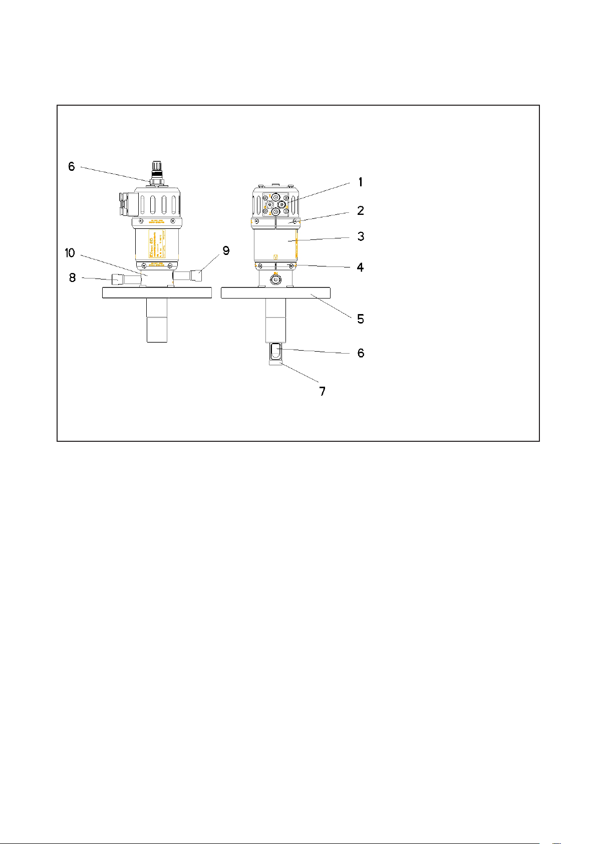
2. Product description
2.1 RF20H (Extract 810 and 820) automatic retractable holder
Components
1. Pneumatic connections 1-4
2. Top housing cramp
3. Drive unit
4. Lower housing cramp
5. Process connection
6. Sensor
7. Insertion rod with protection cage
8. Cleaning port “IN”
Fig. 1: Retractable holder
Variations
Retractable holders are attached to tanks or piping
by an applicable process connection. In order to
comply with the various process properties the
RF20H (Extract 810 and 820) retractable holder is
fabricated of stainless steel, Alloy C-22 or plastic.
You can further choose between different process
and cleaning ports, sealing materials, and sensors.
Drive
Compressed air is supplied via the pneumatic
connections on the drive unit. The drive unit inserts
the insertion rod in the process medium up to the
maximal insertion depth. For safety reasons this is
only possible with a sensor installed.
9. Cleaning port “OUT”
10. Cleaning chamber
Service
Cleaning, rinsing and calibration of the sensor
is possible while the process is running. For
this purpose the holder must be moved to the
“service” position. Another pneumatic position
signal feedback is given when the final position is
reached. In the “service” position the insertion rod
seals the cleaning chamber against the process
to prevent leakage of process liquid. The required
liquid is introduced into the cleaning chamber via
the cleaning port “IN” and subsequently drained via
the cleaning port “OUT”.
Measuring
When reaching the final position of the “measuring”
position, the control receives a pneumatic position
feedback signal. In this position the sensor head is
immersed in the drive unit and cannot be removed.
The sensor measures the chemical or physical
properties of the process liquid.
IM 12B06K05-E-E
Page 7
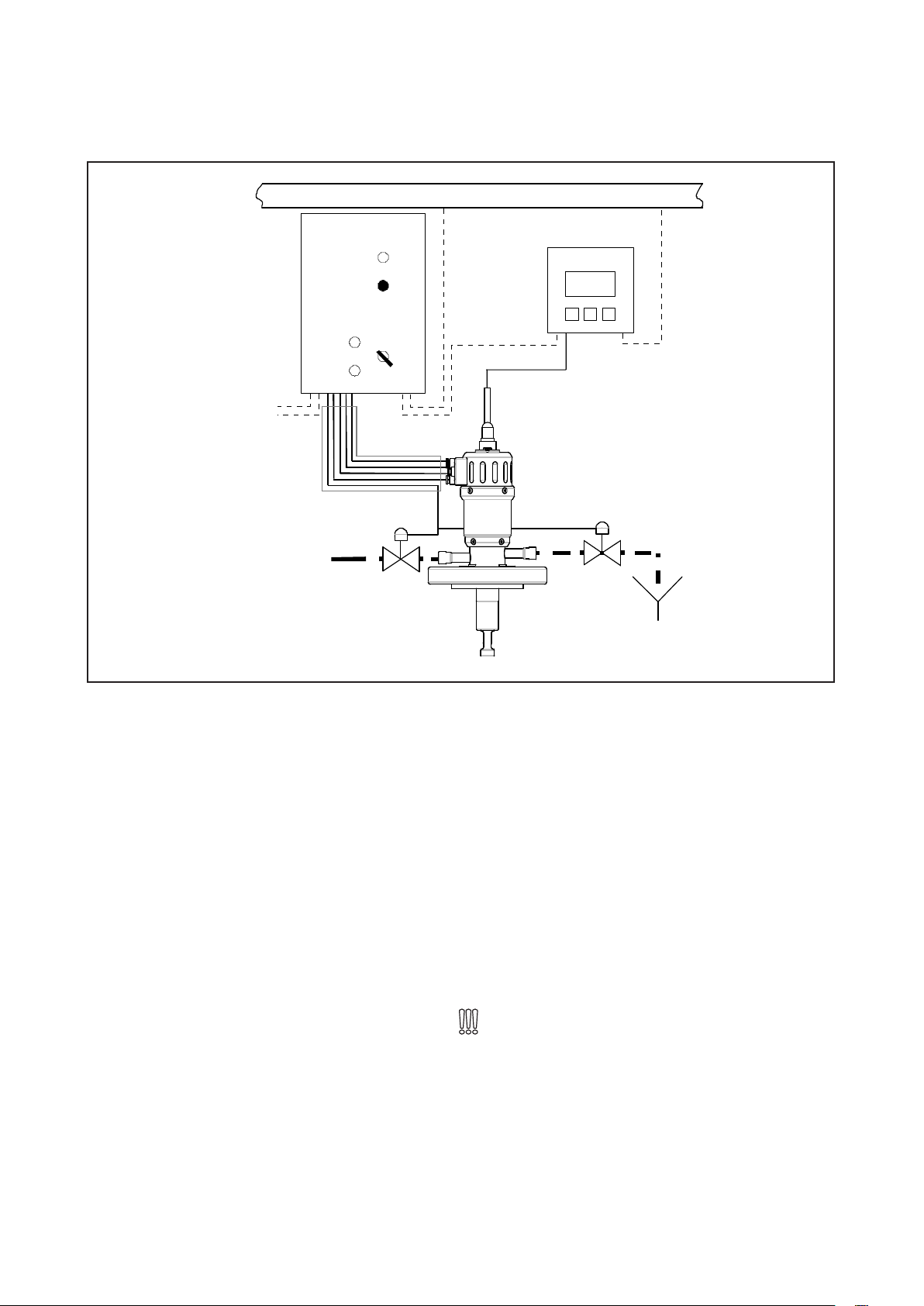
2.2 Process integration
24V DC
Air 4-6 bar
7
Process Control System
RF20M
(Exmatic 450)
Transmitter
Cleaning
solution
Fig. 2: Process flow
Control
The RF20H (Extract 810 and 820) retractable holder
can be operated by the automatic control EXmatic.
It optimally matches the functions of the holder.
Transmitter
The retractable holder inserts a sensor in the
process liquid transmitting its measuring results to a
transmitter.
Drain
Process control
The external control and the transmitter can
be connected to a process control unit. The
measuring and cleaning intervals are then controlled
automatically according to the measuring results.
Pressure Temperature
The choice of the applicable holder is subject to
the pressure and temperature conditions of the
process. The retractable holder of stainless steel or
Alloy C-22 can be used for a pressure of up to 16
bar and the plastic model up to 10 bar according to
the temperature. The process temperature should
be between -10° and 140°C.
Observe pressure and temperature charts in
chapter 8!
Installation position
The operation of the holder is generally possible in
any position. The reliability of the measuring results
depends on the properties of the selected sensor.
The sensor should be connected in a position less
than 15º to the hozizontal plane.
IM 12B06K05-E-E
Page 8
8
CAU TI ON!
DAN GE R!
3. Delivery
3.1 Package contents
The retractable holder is inspected at the factory
and delivered ready for installation in a packaging
providing optimal protection for the holder.
Package contents:
• RF20H (Extract 810 and 820) holder
• hexagon key 2.5mm
• 4 spare screws M 4 x 8 (DIN 912)
• 2 spacer for sensors
• operation manual
For the RF20H (Extract 810) S.S./Hastelloy holder
you will additionally receive a material certificate
Store the holder in the packaging. This
ensures optimal protection until the
installation.
3.2 Checking the delivery
Before approving the retractable holder
for installation the following should be
ensured:
• packaging and device are in apparent
good order.
• the data plate of the retractable holder
corresponds to the specifications on the
order.
EXtract 810
4404-FPM-255-D50-G14-PN
SN: 8000008
P:16 bar T:140ºC
made in germany www.e-p-e.com
Fig. 3a: Data plate Alloy C-22
Fig. 3b: Data plate Plastic
In case of further inquiries please directly
contact your dealer.
IM 12B06K05-E-E
Page 9
9
CAU TI ON!
DAN GE R!
CAU TI ON!
DAN GE R!
CAU TI ON!
DAN GE R!
CAU TI ON!
DAN GE R!
CAU TI ON!
4. Installation
4.1 Preparing the system
Ensure that
• Sufficient working space for operation of
the retractable holder is available.
• The process is shut off.
• Tank and tubing are pressure-free, empty
and clean.
• Connection flange and process
connection of the retractable holder fit
together.
• The process seal is positioned on the
connection flange.
• Ensure that there is no potentially
explosive atmosphere
4.2 Preparing the holder
The holder must be in the “service”
position!
• The insertion rod (process end) is completely
inserted in the cleaning chamber.
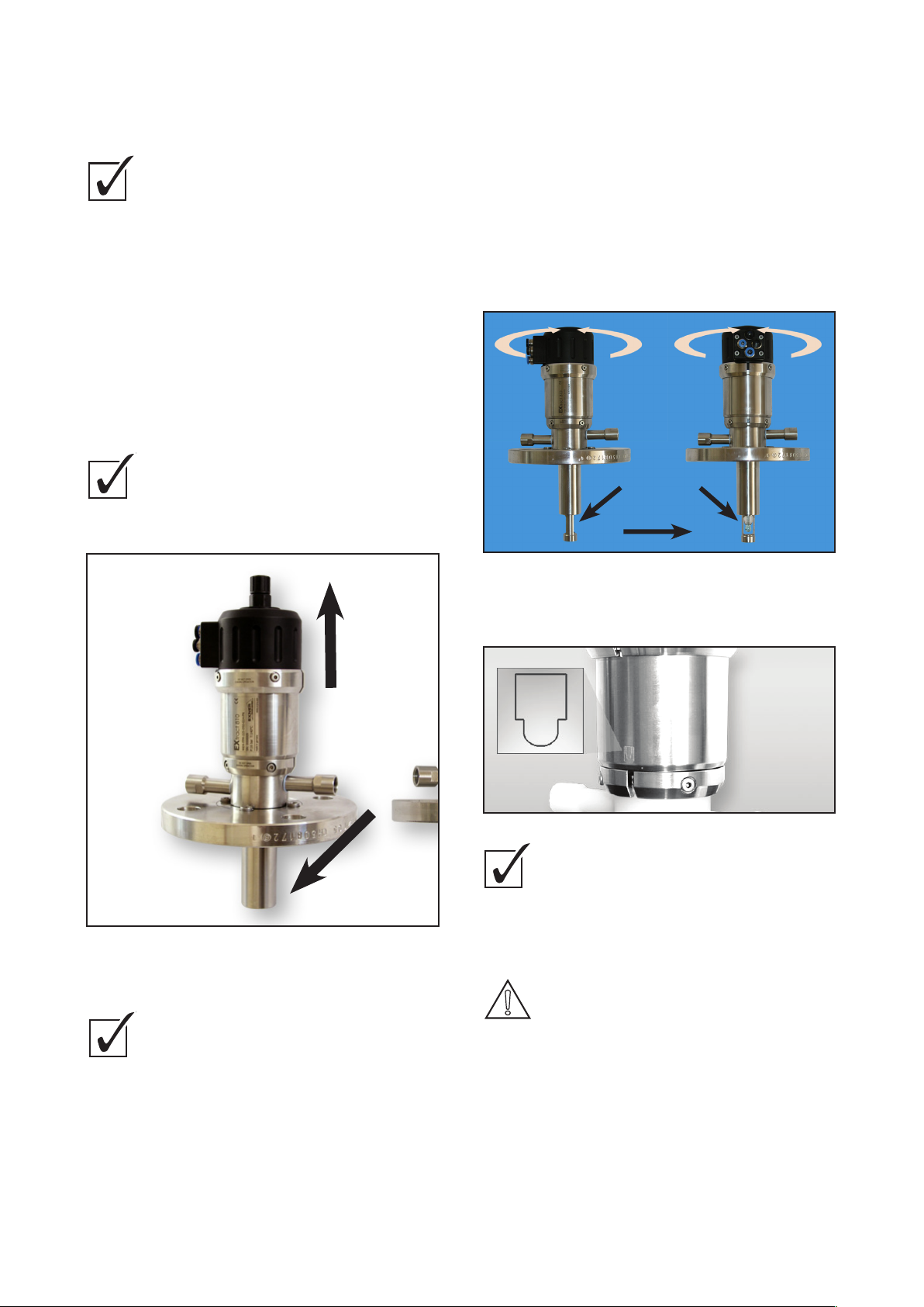
4.4 Adjusting the protection cage
A protection cage is fitted to the lower end of the
insertion rod and can be adjusted with the flow
direction. The symbol on the drive unit cylinder
indicates the position of the opening in the insertion
rod. If the symbol is parallel to the flow direction the
insertion rod is fully flown through. If the symbols
are vertical to the flow the sensor is fully protected
from direct flow. The insertion rod can be adjusted
in any intermediate position.
A
flow direction
B
Fig. 4: “service” position
4.3 Installing the holder
Prior to installation, ensure this:
• The system is prepared (chapter 4.1).
• The holder is prepared (chapter 4.2).
How to install the holder:
• Position retractable holder on process
seal.
• Tighten process connection.
A) Sensor maximally streamed
B) Sensor minimally streamed
Fig. 5: Protection cage
Fig. 6: Symbol
Ensure that:
• The process is shut off.
• Tank piping and tubing are pressure-free,
empty and clean.
• There is no potentially explosive atmosphere
DAN GE R!
Leakage of process liquid when
housing cramp is opened during
running process!
Burns or tissue destruction depending on
process liquid property.
• Stop process!
• Tanks and tubing must be pressure-free!
How to adjust the protection cage:
• Loosen screws of lower housing cramp.
• Rotate drive unit and adjust symbol in flow direction.
• Tighten screws of lower housing cramp.
IM 12B06K05-E-E
Page 10

10
CAU TI ON!
CAU TI ON!
DAN GE R!
4.5 Installing the cleaning pipes
Cleaning of the sensor is possible while the process
is running. This requires supply and draining of
cleaning liquid to the cleaning chamber. If cleaning
of the sensor is not desired the cleaning ports must
be sealed by pegs.
A
B
How to install the cleaning pipes:
1) Install valve and dirt trap in the cleaning
pipe for the cleaning liquid supply.
2) Attach supply cleaning pipe to the
cleaning port “IN”. .
3) Install valve in cleaning pipe for drainage
of the cleaning liquid.
4) Attach cleaning pipe to the cleaning port
“OUT”.
5) Check all connections for tightness.
To avoid premature contamination of the
sensor the pressure of the cleaning liquid
should be at least 1 bar!
4.6 Installing the pneumatic tubes
The RF20H (Extract 810 and 820) retractable holder
is operated with compressed air. The extension
of the cylinder of the drive unit is fitted with four
compressed air connections.
Fig. 7: Cleaning ports
A Cleaning port “IN”
B Cleaning port “OUT”
DAN GE R!
Leakage of process liquid through the
open cleaning port!
Burns or tissue destruction depending on
process liquid property.
• Cleaning pipes must be installed
or
• cleaning ports “IN” and “OUT” must be
sealed by pegs!
CAU TI ON!
If the process pressure is higher than
the cleaning pressure
process liquid enters the cleaning pipes
while the holder is moving to the service
position.
• A cleaning pipe with valve must be
installed at the cleaning ports “IN” and
“OUT”!
CAU TI ON!
If the cleaning liquid pressure exceeds
6 bar
holder and sensor may be damaged.
CAU TI ON!
• Install a pressure reducer, if necessary!
Contaminated cleaning liquid
can cause damage to the holder.
• Install a cleaning pipe with dirt trap at the
cleaning port “IN”!
IM 12B06K05-E-E
Fig. 8: Pneumatic connections 1 - 4
CAU TI ON!
Emitted compressed air
can cause material or personal damage.
Ensure tightness of pneumatic tubes before
supplying compressed air.
CAU TI ON!
Contaminated compressed air
causes damages to the drive unit!
• Use filtered (40 µm), water-free and
deoiled compressed air!
CAU TI ON!
You will need:
• 2 pneumatic tubes ø = 4mm
• 2 pneumatic tubes ø = 6mm.
Page 11

11
How to install the pneumatic tubes:
1 Insert pneumatic tube ø = 6mm in connection 1
(blue) for the air supply “service” position.
2 Insert pneumatic tube ø= 6mm in connection 2
(black) for air supply, “meassuring position”.
3 Insert pneumatic tube ø = 4mm in connection 3
(blue) for the reply signal “service” position.
4 Insert pneumatic tube ø = 4mm in connection 4
(black) for the reply signal “measuring position”.
4.7 Installing the sensor
Sensors with a diameter of 12mm and a connection
thread PG 13.5 must be used in the RF20H (Extract
810 and 820) retractable holder.
The length of the sensor depends on the sensor
type and the selected holder.
Observe information in chapter 8.4
“Sensors”!
Ensure that
• the holder is in the “service” position.
• all seals connected to the sensor are available.
• the sensor is not longer than the specified length.
> 5mm
Wrong!
5 - 7mm
Right!
How to install the sensor:
1) Insert sensor and tighten
2) Attach sensor cable
Fig. 9: Sensor filled with gel (top), sensor filled
with liquid (bottom)
CAU TI ON!
To long Sensors
could be damaged during installation
• Check the sensor length and use delivered
spacer if necessary!
The retractable unit is now ready for operation.
IM 12B06K05-E-E
Page 12

12
CAU TI ON!
DAN GE R!
CAU TI ON!
CAU TI ON!
DAN GE R!
CAU TI ON!
DAN GE R!
5. Operation
5.1 Commissioning the holder
DAN GE R!
Risk of injury by leaking process liquid!
Burns or tissue destruction depending on
process liquid property.
• Wear goggles and protective clothing!
• Check all seals and connections of holder
before starting the process.
Wear goggles and protective clothing during
commissioning of the holder!
Prior to the commissioning ensure the following:
• Seals are complete and in good working condition.
• Sensor is installed and tightened.
• Cleaning ports are sealed with pegs.
or:
• Cleaning pipes are installed and tight.
• Pneumatic tubes are installed and tight.
• Protection cage is adjusted correctly.
5.2 Automatic operation of the holder
An external control is required for automatic
operation of the retractable holder.
Observe the functions of the pneumatic
connections!
Connection 1: Air supply “service” position
Connection 2: Air supply “measuring” position.
Connection 3: Reply “service” position
Connection 4: Reply “measuring” position.
Use the external control to move the
retractable holder from the “service” position
to the “measuring” position and vice versa.
IM 12B06K05-E-E
Page 13

13
CAU TI ON!
DAN GE R!
servicing works.
manual!
manufacturer!
before disconnecting the holder from the process
CAU TI ON!
DAN GE R!
CAU TI ON!
DAN GE R!
CAU TI ON!
CAU TI ON!
DAN GE R!
6 Servicing
6. Servicing
6.1 Servicing instructions
• Establish a service plan adapted to your process!
• Leave servicing works to qualified staff.
• Always wear applicable protective clothes when
performing servicing works.
• Do only perform the service works described in
the operation manual!
• Constructional modifications must be agreed with
the manufacturer!
• Tubing and tanks must be pressure-free, empty
and clean before disconnecting the holder from
the process
• Ensure that there is no potentially explosive
atmosphere
6.2 Checking wetted sealings
The retractable holder is fitted with an inspection
window situated between the lower housing
cramps.
Check inspection window for leaking
process liquid on a regular basis.
6.3 Removing the sensor
How to remove the sensor:
1) Move holder to “service” position.
2) Remove sensor cable.
3) Remove PG cable gland.
4) Remove sensor.
DAN GE R!
Broken glass sensor!
Broken glass may damage the wetted
sealings.
• Check wetted sealings and replace if
necessary.
• Observe instructions in chapter 6.6!
6.4 Removing the pneumatic tubes
How to remove all four pneumatic tubes:
1) Move holder to "service" position.
2) Stop compressed air supply.
3) Press plastic ring “A” on pneumatic
connection.
4) At the same time pull pipe “B”.
Fig. 10: Inspection window on lower housing
cramp
WARN IN G!
Process liquid leaking on the inspection
window!
Risk depending on process liquid property!
• Replace wetted sealings.
• Observe instructions in chapter 6.6!
Fig. 11: Removing the pneumatic tubes
IM 12B06K05-E-E
Page 14

14
CAU TI ON!
CAU TI ON!
DAN GE R!
CAU TI ON!
DAN GE R!
CAU TI ON!
CAU TI ON!
DAN GE R!
CAU TI ON!
DAN GE R!
6.5 Removing the cleaning chamber
with process connection
DAN GE R!
System is under pressure.
Process liquid will leak when holder
is disconnected from process in an
inappropriate way.
• Tubing or tanks must be pressure-free,
empty, clean and without potentially
explosive atmosphere.
Interrupt the process.
Ensure that the system is pressure-free,
empty, clean and without potentially
explosive atmosphere.
How to remove the cleaning chamber:
1) Move holder to “service” position.
2) Switch off compressed air supply.
WARN IN G!
Emitted compressed air
can cause material damage or personal injury.
• Switch off compressed air supply before
removing the pneumatic tubes.
3) Remove pneumatic tubes (chap. 6.4).
4) Remove sensor (chap. 6.3).
5) Loosen process connection.
6) Remove process seals and holder.
7) Loosen lower housing cramp screws (Fig. 10).
8) Disconnect cleaning chamber with process
connection “A” from drive unit “D”.
9) Remove cleaning cartridge from insertion rod “C”.
6.6 Replacing the wetted sealings
DAN GE R!
System is under pressure.
Process liquid will leak when holder
is disconnected from process in an
inappropriate way.
• Ensure that system is pressure-free before
replacing the sealings.
• Drain and clean tubing or tanks.
• Ensure that there is no potentially
explosive atmosphere
WARN IN G!
Emitted compressed air
can cause material damage or personal
injury.
• Switch off compressed air supply before
removing the pneumatic tubes.
Install the seals chosen according to the
holder and the process!
• Do only use original parts!
How to replace the seals:
1) Remove cleaning chamber with process
connection (chap. 6.5).
2) Remove and replace outer O rings “A”, "B" and
inner O ring "C" on insertion rod.
A B C D
Fig. 12: Removing the cleaning chamber and
process connection (refer to image!)
A) Cleaning chamber with process connection
B) Cleaning cartridge
C) Insertion rod
D) Drive unit
IM 12B06K05-E-E
B A
Fig. 13: O rings on insertion rod
O rings ø in [mm] A 18.72 x 2.62
B 10.77 x 2.62
B is left out
3) Remove and replace O rings “D” on cleaning
cartridge.
D
Fig. 14:O ring on cleaning cartridge
O ring ø in [mm] D 21.95 x 1.78
Page 15

15
Scraper
∅
in [mm]
E 19 x 6 x 1
O ring
∅
in [mm]
F 21.89 x 2.62
Scraper
∅
in [mm]
E 19 x 6 x 1
O ring
∅
in [mm]
F 21.89 x 2.62
Scraper
∅
in [mm]
E 19 x 6 x 1
O ring
∅
in [mm]
F 21.89 x 2.62
CAU TI ON!
CAU TI ON!
DAN GE R!
CAU TI ON!
DAN GE R!
6 Servicing
insertion rod.
pneumatic tubes.
6.5).
A Cylinder extension
B Piston
C Insertion rod
D Cylinder
E 2 x M4 x 8
F 2 x pins
4) Remove PTFE scraper “E” on cleaning chamber
5) Remove and replace O ring “F”.
6) Position PTFE scraper “E” on O ring “F”.
F
Fig. 15: O rings/scraper on cleaning chamber
Scraper ø in [mm] E 19 x 6 x 1
O ring ø in [mm] F 21.89 x 2.62
Remove the PTFE scraper (E) as follows:
6.7 Removing the insertion rod
DAN GE R!
System is under pressure.
Process liquid will leak when holder
E
• Ensure that system is pressure-free before
• Drain and clean tubing or tanks.
WARN IN G!
Emitted compressed air
can cause material damage or personal injury.
• Switch off compressed air supply before
How to remove the insertion rod from
1) Remove cleaning chamber and process
2) Remove outer O rings on insertion rod
3) Remove top housing cramp screws.
4) Remove cylinder “D” from cylinder
is disconnected from process in an
inappropriate way.
removing the insertion rod.
removing the pneumatic tubes.
the drive unit:
connection (chap. 6.5).
(Fig. 13: “A” and “B”).
extension “A” (Fig. 17)
Only applicable for RF20H (Extract 810 and 820)
811/812 with separated cleaning chamber:
7) Separated cleaning chamber: Remove and
replace O ring “G”.
Fig. 16: Cleaning chamber 811/821
O ring ø in [mm] G 30 x 1.5
Fig. 17: Removing the cylinder
A Cylinder extension
B Piston
F
C Insertion rod
D Cylinder
5) Loosen screws “E” and remove pins “F” (Fig. 18).
Fig. 18: Removing the fixing elements
E 2 x M4 x 8
F 2 x pins
6) Remove insertion rod “C” from piston “B”.
IM 12B06K05-E-E
Page 16

16
CAU TI ON!
DAN GE R!
CAU TI ON!
DAN GE R!
CAU TI ON!
CAU TI ON!
DAN GE R!
CAU TI ON!
DAN GE R!
6.8 Installing the insertion rod
The descriptions refer to Fig. 17 and Fig. 18
in chap. 6.7 Removing the insertion rod!
How to assemble the insertion rod and the
drive unit:
1) Adjust slots in insertion rod “C” to piston “B”
and put together.
2) Insert pins “F”
3) Tighten screws “E”.
4) Grease inside wall of cylinder “D”.
5) Slide cylinder “D” over insertion rod “C”.
6) Adjust cylinder “D” to cylinder extension “A”.
7) Press until cylinder snaps into place.
8) Bring top housing cramp in position
and tighten screws.
9) Insert O rings at insertion rod
(Fig. 13: “A” and “B”).
6.9 Assembling the drive unit and
cleaning chamber
Ensure that
• all seals are installed and in good working
condition.
• insertion rod and drive unit are assembled
(chap. 6.8).
How to install the cleaning chamber:
1) Insert cleaning cartridge in cleaning chamber until
it snaps into place.
2) Insert drive unit with insertion rod.
3) Press both components tightly together.
4) Adjust drive unit until it snaps into place in the
cleaning chamber.
5) Adjust protection cage (chap. 4.4).
6) Bring lower housing cramp in position and tighten.
The holder can now be reinstalled in the
process. Also observe the instructions in
chapter 4:
• 4.3 Installing the holder
• 4.4 Adjusting the protection cage
• 4.5 Installing the cleaning
• 4.6 Installing the pneumatic
• 4.7 Installing the sensor
6.10 Replacing the drive unit
• Ensure that there is no potentially
explosive atmosphere
WARN IN G!
Emitted compressed air
can cause material damage or personal injury.
• Switch off compressed air supply before
removing the pneumatic tubes.
The new drive unit can now be installed:
Prior to installation,
• remove cleaning chamber with process
connection (chap. 6.5).
• remove insertion rod (chap. 6.8).
• Clean and dispose off cylinder, cylinder
extension, pivot, housing cramps, if required.
How to install the new drive unit:
1) Remove screws from top housing cramp.
2) Remove cylinder “D” from cylinder extension “A”
(Fig. 17).
3) Install insertion rod (chap. 6.8).
4) Assemble the drive unit and cleaning chamber
(chap. 6.9).
6.11 Servicing plan
Carry out maintenance works in the
recommended intervals!
weekly
Checking wetted sealings (chap. 6.2)
Check process connection.
Check cleaning pipes.
Check pneumatic connections.
quarterly
Check and tighten screws of top and lower
housing cramps.
once a year
Replace wetted sealings (chap. 6.6).
Remove and inspect insertion rod (chap. 6.7).
every 3 years
Replace drive unit (chap. 6.10).
6.12 Disposal
Holder
Ensure that the holder is free from
hazardous and toxic substances. Depending
on your material the individual components
must be disposed off separately.
DAN GE R!
System is under pressure.
Process liquid will leak when holder
is disconnected from process in an
inappropriate way.
• Ensure that system is pressure-free before
replacing the drive unit.
• Drain and clean tubing or tanks.
IM 12B06K05-E-E
Observe regulations and rules for waste
disposal applicable in the operator’s country
and at the site of use.
Packaging
The packaging is made of card board and
can be disposed off with the waste paper.
Page 17

7. Trouble shooting
Refer to the instructions and warnings in the specified chapters.
7.1 Holder does not move from the "service" position to the "measuring" position
possible reason measure
no compressed air check pneumatic tubes (chap. 6.4, 4.6)
pressure too low pressure must be between 4 and 6 bar (chap. 4.6)
no sensor Installing the sensor (chap. 4.7)
loose sensor tighten sensor (chap. 4.7)
7.2 Holder does not move from the "measuring" position to the "service" position
possible reason measure
no compressed air check pneumatic tubes (chap. 6.4, 4.6)
pressure too low Pressure must be between 4 and 6 bar (chap. 4.6)
Insertion rod or protection cage is blocked. • Preparing the system (chap. 4.1)
• Holder remains in “measuring” position
• Removing the cleaning chamber with process
connection (chap. 6.5)
• Removing the insertion rod (chap. 6.7)
17
7.3 Incorrect position reply
possible reason measure
pneumatic tubes are connected incorrectly check pneumatic tubes (chap. 6.4, 4.6)
7.4 No position reply
possible reason measure
no compressed air check pneumatic tubes (chap. 6.4, 4.6)
pressure too low pressure must be between 4 and 6 bar (chap. 4.6)
drive unit defect Replacing the drive unit (chap. 6.10)
7.5 Frequent contamination of sensor
possible reason measure
cleaning pipes incorrectly connected check cleaning pipes (chap. 4.5)
cleaning liquid pressure too low raise cleaning pressure.
cleaning chamber is blocked pressure must be between 1 and 4 bar (chap. 4.6)
cleaning liquid not adequate choose adequate cleaning liquid
cleaning period too short extend cleaning period
cleaning interval too long reduce cleaning interval
IM 12B06K05-E-E
Page 18

18
7.6 Sensor breaks frequently
possible reason measure
sensor too long choose adequate sensor (chap. 4.7)
seals on sensor are missing insert seals on sensor (chap. 4.7)
Process liquid contains solids Adjusting the protection cage(chap. 4.4)
7.7 Leakage of process liquid at inspection window
possible reason measure
wetted sealings are defect Replacing the wetted sealings (chap. 6.6)
7.8 Compressed air emitted at inspection window
possible reason measure
drive unit defect Replacing the drive unitit (chap. 6.10)
IM 12B06K05-E-E
Page 19

8. Technical specifications
8.1 Standards
Pressure equipment directive
8.2 Material properties RF20H (Extract 810 and 820)
Wetted components
Holder
metal plastic seals
RF20H 1.4404/316L Alloy C22, 2.4602 PVDF PEEK EPDM / FPM / FFKM
Drive unit)
cylinder cylinder extension seals
RF20H 1.4404/316 PA66 GF30 EPDM
8.3 Cleaning ports
Thread
without gland G 1/8" (internal)
G¼" (internal)
thread with gland NPT ¼" (internal)
19
Cleaning pressure
1 - 4 bar
8.4 Sensors RF20H (Extract 810 and 820)
Gel filled sensor
l [mm] d [mm] PG
RF20H 225 12 13.5
Sensor filled with liquid with refill connection
l [mm] d [mm] PG
RF20H 280 12 13.5
8.5 Pneumatic equipment
Pneumatic tubes
ø - external ø - internal
for control air 6 mm 4 mm
for position reply 4 mm 2 mm
Compressed air
• Filtered 40µm, water- and oil free
• 4 - 6 bar
• no continuous air consumption!
IM 12B06K05-E-E
Page 20

20
EXTRACT EXTRACT
810 811 820 821
350 480 350 480
A B C D
Flange 4404 Flange C22 NPT TriClamp
8.6 Dimensions
Holder
Dimensions RF20H RF20H
Metal (Extract 810) Plastic (Extract 820)
A1 [mm] 180 180
A2 [mm] 350 350
B [mm] 95 95
Process connections RF20H Metal (Extract 810)
A B C D
Flange 4404 Flange C22 NPT TriClamp
Dimensions
E1 [mm] 71 66 34 39
E2 [mm] 107 102 70 75
D1 [mm] 19 19 19 19
D2 [mm] 31 31 31 31
D3 [mm] - - - 64
IM 12B06K05-E-E
Page 21

Process connections RF20H in Plastic (Extract 820)
8 Technical specifications
A B
Flange NPT
8 Technical specifications
0
5
10
15
20
-10
0
10
20
30
40
50
60
70
80
90
100
110
120
130
140
TS in [°C]
PS in [bar]
1.4404 und 2.4602
TRACT 810/811
A B
Flange NPT
Dimensions
E1 [mm] 58 29
E2 [mm] 94 65
D1 [mm] 19 19
D2 [mm] 31 30.5
8.7 Ambient conditions
Ambient temperature - 10 - 70 °C
Transport and storage temperature - 20 - 80 °C
8.8 Process conditions RF20H in Metal (Extract 810)
max. allowed pressure PS: 16 bar
max. allowed temperature TS: 140 °C
21
20
15
10
5
PS in [bar]
0
-10
0
10
Fig. 19: Pressure temperature diagram RF20H Metal (Extract 820)
8.9 Process conditions RF20H in Plastic (Extract 820)
max. allowed pressure PS 10 bar
max. allowed temperature TS 140 °C
12
10
8
6
4
PS in [bar]
2
0
0
10
-10
20
30
20
30
40
50
TS in [°C]
1.4404 und 2.4602
40
50
TS in [°C]
60
70
80
90
100
110
120
60
70
80
90
100
110
120
130
140
130
140
Fig. 20: Pressure temperature diagram RF20H in Plastic (Extract 810)
IM 12B06K05-E-E
Page 22

22
8.10 Ordering structure RF20H (Extract 810 and 820) S.S./Hast.
RF20H (Extract 810 and 820)
RF20H pH-Retractable Holder RF20H remark
Material (wetted parts) -PP PP Extract 820
-PF PVDF Extract 820
-PK PEEK Extract 820
-SS Stainless Steel 1.4404 / 316L Extract 810
-HC Alloy C22 2.4602 Extract 810
Sealing Material -EPD EPDM
(wetted sealings) -FPM FPM (Viton)
-FKM FFKM (Kalrez)
Sensor -225 Suitable for 225mm PG13.5 Gel-filled
-280 Suitable for 280mm PG13.5 Liquid-filled
Process Connection -D32 Flange DN32 PN16 SS/Hast only
-D40 Flange DN40 PN16 SS/Hast only
-D50 Flange DN50 PN16
-A14 Flange ANSI 1 1/4” 150lbs SS/Hast only
-A12 Flange ANSI 1 1/2” 150lbs SS/Hast only
-A20 Flange ANSI 2” 150lbs
-N14 NPT M 1 1/4”
-T20 Tri Clamp 2” SS/Hast only
Cleaning Connection -G18 G 1/8” thread female
-G14 G 1/4” thread female
-N14 1/4” NPT female
Position switch -PN Pneumatic
Spareparts
Partnumber Description
10/2-123-40-001 Sealing Set EPDM
10/2-123-41-001 Sealing Set FPM
10/2-123-42-001 Sealing Set FFKM (Kalrez)
10/2-075-03-001 Drive Unit - sensor 225/325 pneum. position switch
10/2-075-03-002 Drive Unit - sensor 280/380 pneum. position switch
10/2-061-33-004 Insertion rod RF20H (Extract 810 and 820) 1.4404 / 316L
10/2-061-34-004 Insertion rod RF20H (Extract 810 and 820) 2.4602 / Alloy C22
10/2-061-22-004 Insertion rod RF20H (Extract 810 and 820) PP
10/2-061-23-004 Insertion rod RF20H (Extract 810 and 820) PVDF/Alloy C22
10/2-061-29-004 Insertion rod RF20H (Extract 810 and 820) PEEK
10/2-086-32-001 Set blind plug G1/8” 1.4301/316 for cleaning chamber
IM 12B06K05-E-E
Page 23

9. Parts and accessories
Drive unit with pneumatic position reply
RF20H (Extract 810 and 820) Part Item number
Metal and Plastic Drive unit for sensor L = 225mm 10/2-075-03-001
Metal and Plastic Drive unit for sensor L = 280mm 10/2-075-03-002
Seal kits
RF20H (Extract 810 and 820) Part Item number
Metal and Plastic Seal kit EPDM 10/2-123-40-001
Seal kit FPM 10/2-123-41-001
Seal kit FFKM 10/2-123-42-001
Insertion rods
RF20H (Extract 810 and 820) Part Item number
Metal Insertion rod 1.4404 / 316L 10/2-061-33-004
Insertion rod 2.4602 / Alloy C22 10/2-061-34-004
Plastic Insertion rod PP 10/2-061-22-004
Insertion rod PVDF / Alloy C22 10/2-061-23-004
Insertion rod PEEK / Alloy C22 10/2-061-29-004
23
Please state serial number of your holder when ordering parts and accessories.
IM 12B06K05-E-E
Page 24

24
10. Certificates
Statement of compliance
Atex certificate
IM 12B06K05-E-E
Page 25

25
IM 12B06K05-E-E
Page 26

26
IM 12B06K05-E-E
Page 27

27
IM 12B06K05-E-E
Page 28

YOKOGAWA ELECTRIC CORPORATION
World Headquarters
9-32, Nakacho 2-chome, Musashino-shi
Tokyo 180-8750
Japan
www.yokogawa.com
YOKOGAWA CORPORATION OF AMERICA
2 Dart Road
Newnan GA 30265
USA
www.yokogawa.com/us
YOKOGAWA EUROPE BV
Euroweg 2
3825 HD AMERSFOORT
The Netherlands
www.yokogawa.com/eu
YOKOGAWA ELECTRIC ASIA Pte. LTD.
5 Bedok South Road
Singapore 469270
Singapore
www.yokogawa.com/sg
YOKOGAWA CHINA CO. LTD.
3F Tower D Cartelo Crocodile Building
No.568 West Tianshan Road Changing District
Shanghai, China
www.yokogawa.com/cn
YOKOGAWA MIDDLE EAST B.S.C.(c)
P.O. Box 10070, Manama
Building 577, Road 2516, Busaiteen 225
Muharraq, Bahrain
www.yokogawa.com/bh
Yokogawa has an extensive sales and
distribution network.
Please refer to the European website
(www.yokogawa.com/eu) to contact your
nearest representative.
IM 12B06K05-E-E
Subject to change without notice Printed in The Netherlands, 01-1012 (A) I
Copyright©
 Loading...