

Page 1

User´s
Model RAMC
Manual
IM 01R01B02-00E-E
Metal Short Stroke ROTAMETER
Rota Yokogawa GmbH & Co. KG
Rheinstr. 8
D-79664 Wehr
Germany
IM 01R01B02-00E-E
©Copyright 2003 (RYG)
14th edition, February 2017 (RYG
Page 2

Blank Page
Page 3

<CONTENTS>
i
Contents
1. Introduction ......................................................................................... 1-1
1.1 For Safe Use of Rotameter RAMC ..................................................................1-2
1.2 Warranty .............................................................................................................1-3
1.3 Notices regarding EMC ....................................................................................1-3
1.4 General description .........................................................................................1-4
1.5 Principle of measurement .............................................................................. 1-4
1.6 Overview ........................................................................................................... 1-5
2. Precautions .........................................................................................2-1
2.1 Transportation and storage ............................................................................2-1
2.2 Installation .......................................................................................................2-1
2.3 Pipe connections ............................................................................................2-1
3. Installation ..........................................................................................3-1
3.1 Installation in the pipeline .............................................................................3-1
3.2 Wiring of electronic transmitter (-E, -H, -J) and limit switches (/K
) .........3-2
4. Start of operation ...............................................................................4-1
4.1 Hints on ow rate measurement ...................................................................4-1
4.2 Pulsation and pressure shock .......................................................................4-1
4.3 Start of operation of electronic transmitter .................................................4-1
5.
Limit switches (Option /K) ...........................................................................................5-1
All Rights Reserved. Copyright © 2003, Rota Yokogawa
IM 01R01B02-00E-E 14th edition January 20, 2017 -00
Page 4

<CONTENTS>ii
6. Electronic Transmitter (-E) .................................................................6-1
6.1 Operation principle .........................................................................................6-1
6.2 Parameter setting ............................................................................................6-1
6.2.1 Selection of indication function (F11) ............................................................... 6-4
6.2.2 Setting the unit (F12 / F13) ................................................................................. 6-5
6.2.3 Totalizer reset (F14) ............................................................................................. 6-7
6.2.4 Selection of temperature unit (F15) ................................................................... 6-7
6.2.5 Setting of damping (F2-) ..................................................................................... 6-8
6.2.6 Selection / Adjustment 4-20 mA / 0-20 mA (F3-) .............................................. 6-8
6.2.7 Pulse output (F34) (Option /CP) ......................................................................... 6-9
6.2.8 Error messages (F4-) ......................................................................................... 6-12
6.2.9 Manual adjustment (F5-) ................................................................................... 6-13
6.2.10 Revision indication (F61/F62) ......................................................................... 6-16
6.2.11 Current output test (F63) ................................................................................. 6-16
6.2.12 Switching between standard / Indicator on extension (F64) ...................... 6-17
6.2.13 Master Reset (F65) ........................................................................................... 6-17
6.2.14 Float blocking indication (F7-) ........................................................................ 6-18
7.
HART - Communication .......................................................................................7- 1
7.1 General .............................................................................................................7-1
7.1.1 Multidrop Mode in the case of using HART 5 .....................................................7-1
7.1.2 Multidrop Mode in the case of using HART 7 .....................................................7-2
7.2 Connection ....................................................................................................... 7-3
7. 3 HART 5 - Menu (Rev 01 DD rev 02) ..............................................................7-4
7.4. Description of the HART 5
- Parameter ........................................................ 7-7
7.4.1 Process variables ..................................................................................................7-8
7.4.2 Diagnostic- and Service-Menu .............................................................................7- 8
7.4.3 Basic-Setup Menu ...............................................................................................7- 14
7.4.4 Detailed-Setup Menu ...........................................................................................7- 14
7.4.5 Review ..................................................................................................................7- 16
IM 01R01B02-00E-E 14th edition January 20, 2017 -00
All Rights Reserved. Copyright © 2003, Rota Yokogawa
Page 5

<CONTENTS>
iii
7.5 HART 7 - Menu (Rev 10 DD rev 01) ............................................................. 7- 17
7.6. Description of the HART 7
7.6.1 Process variables ................................................................................................7-29
7.6.2 Diagnostic- and Service-Menu ...........................................................................7-30
7.6.3 Basic- Setup Menu .............................................................................................7-37
7.6.4 Detailed- Setup Menu ........................................................................................7-37
7.6.5 Write protect menu ..............................................................................................7-40
7.6.6 Review Menu ........................................................................................................7-40
7.6.7 Burst Mode (Only available in HART 7) .............................................................7-40
7.6.8 Event Notication (Only available in HART 7) ................................................... 7-45
7.6.9 Trend conguration (Only available in HART 7) ................................................7-48
- Parameter ...................................................... 7-29
7.7 Maintenance ................................................................................................... 7-49
7.7.1 Function test .........................................................................................................7-49
7.7.2 Troubleshooting .................................................................................................... 7-49
8.
Service .......................................................................................................... 8-1
8.1 Maintenance ....................................................................................................8-1
8.1.1 Function test ......................................................................................................... 8-1
8.1.2 Measuring tube, oat ........................................................................................... 8-1
8.1.3 Explosion drawing
8.1.4 Electronic transmitter .......................................................................................... 8-3
8.1.5 Exchange of EEPROM and scale ....................................................................... 8-3
8.1.6 Exchange of indicator .......................................................................................... 8-4
8.1.7 Troubleshooting .................................................................................................... 8-4
................................................................................................................. 8-2
8.2 Template for sending back to service ..........................................................8-6
All Rights Reserved. Copyright © 2003, Rota Yokogawa
IM 01R01B02-00E-E 14th edition January 20, 2017 -00
Page 6

<CONTENTS>iv
9. Technical Data ....................................................................................9-1
9.1 Model- and suffix-codes .................................................................................9-1
9.2 Options ............................................................................................................9-2
9.3 Specications ..................................................................................................9-5
9.4 Dimensions and weights..............................................................................9-19
9.5 Temperature graphs for RAMC metal design, standard and intrinsic safe ....9-22
10.
Explosion-protected Type Instruments .......................................... 10-1
10.1 General ......................................................................................................... 10-2
10.1.1 Intrinsic safety ................................................................................................. 10-2
10.1.2 Flame proof ...................................................................................................... 10-2
10.2
10.3
10.4
10.5
Intrinsically safe ATEX certied components (/KS1) .................................10-3
10.2.1 Technical data .................................................................................................. 10-3
10.2.2 Installation ........................................................................................................ 10-4
10.2.3 Marking ............................................................................................................. 10-4
Intrinsically safe ATEX certied components for category 3G (/KS3) .....10-5
10.3.1 Technical data .................................................................................................. 10-5
10.3.2 Marking ............................................................................................................. 10-6
Intrinsically safe IECEx- certied components (/ES1) ..................................10-7
10.4.1 Technical data .................................................................................................. 10-7
10.4.2 Installation ........................................................................................................ 10-8
10.4.3 Marking ............................................................................................................. 10-8
Intrinsically safe IECEx- components for category 3G (/ES3) ...................10-9
10.5.1 Technical data .................................................................................................. 10-9
10.5.2 Marking ............................................................................................................. 10-9
10.6 Intrinsically safe INMETRO (Brazil) components (/US1) ................................10-10
10.6.1 Technical data .................................................................................................10-10
10.6.2 Installation .......................................................................................................10-10
10.6.3 Marking ............................................................................................................10-10
IM 01R01B02-00E-E 14th edition January 20, 2017 -00
All Rights Reserved. Copyright © 2003, Rota Yokogawa
Page 7

<CONTENTS>
v
10.7 Intrinsically safe FM / CSA (USA + Canada) components (/FS1, /CS1) ......... 10-11
10.7.1 Electronic transmitter (/FS1 for USA, /CS1 for Canada) ..............................10-11
10.7.2 Limit switches option /K1 ... /K10 (/FS1 for USA)..........................................10-14
10.7.3 Limit switches option /K1 ... /K3 (/CS1 for Canada) .....................................10-14
10.8 Intrinsically safe NEPSI (China) certied RAMC (/NS1) ................................. 10-20
10.9 Intrinsically safe EAC (Russia, Belarus, Kazakhstan)certied RAMC (/GS1)
............................................................................................................................. 10-21
10.10 Intrinsically safe
PESO (India) certied RAMC .............................................. 10-21
10.11 Flame proof and dust proof ATEX certied RAMC (/KF1) ..................10-22
10.11.1 Technical data ............................................................................................... 10-22
10.11.2 Installation ..................................................................................................... 10-23
10.11.3 Operation ....................................................................................................... 10-23
10.12 Flame proof and dust proof IECEx certied RAMC (/EF1) .................10-24
10.12.1 Technical data ............................................................................................... 10-24
10.12.2 Installation .................................................................................................... 10-25
10.12.3 Operation ...................................................................................................... 10-25
10.13 Intrinsically safe ATEX certied components in dust proof RAMC-housing
(/KS2) .........................................................................................................10-26
10.14 Intrinsically safe IECEx certied components in dust proof RAMC- .........
housing (/ES2) ..........................................................................................10-26
10.15 Flame proof and dust proof NEPSI (China) certied RAMC (/NF1) ....10-27
10.15.1 Technical data ............................................................................................... 10-27
10.15.2 Installation .................................................................................................... 10-27
10.15.3 Operation ...................................................................................................... 10-28
10.16 Flame proof EAC (Russia, Belarus, Kazakhstan) certied RAMC (/GF1) . 10-28
10.16.1 Technical data ............................................................................................... 10-28
10.16.2 Installation
10.16.3 Operation ........................................................................................................................10-28
All Rights Reserved. Copyright © 2003, Rota Yokogawa
.....................................................................................................................10-28
IM 01R01B02-00E-E 14th edition January 20, 2017 -00
Page 8

<CONTENTS>vi
10.17 ATEX registrated non-electrical RAMC (/KC1) ...............................................10-29
10.17.1 Technical data ............................................................................................... 10-29
10.17.2 Safety Instructions ....................................................................................... 10-29
10.17.3 Marking .......................................................................................................... 10-29
10.18 EAC certied non-electrical RAMC (/GC1) ..................................................... 10-30
10.18.1 Technical data ............................................................................................... 10-30
10.18.2 Safety Instructions ....................................................................................... 10-30
10.18.3 Marking ......................................................................................................... 10-30
10.19
10.20
Flame proof and dust proof RAMC with Taiwan ........................................ 10-31
Flame proof and dust proof PESO (India) certied RAMC ........................... 10-31
11. Instructions for PED ....................................................................... 11-1
APPENDIX 1. SOFTWARE CHANGE HISTORY ................................. A1-1
APPENDIX 2. Safety Instrumented Systems Installation .................A2-1
A2.1 Scope and Purpose .................................................................................... A2-1
A2.2 Using RAMC for a SIS Application ........................................................... A2-1
A2.2.1 Safety Function.................................................................................................A2-1
A2.2.2 Diagnostic Response Time ..............................................................................A2-2
A2.2.3 Setup ..................................................................................................................A2-2
A2.2.4 Proof Testing ..................................................................................................... A2-2
A2.2.5 Repair and replacement ..................................................................................A2-2
A2.2.6 Startup Time ......................................................................................................A2-3
A2.2.7 Reliability data ..................................................................................................A2-3
A2.2.8 Lifetime limits ...................................................................................................A2-3
A2.2.9 Environmental limits ........................................................................................A2-3
A2.2.10 Application limits ............................................................................................A2-3
A2.3 Denitions and Abbreviations ................................................................... A2-4
A2.3.1 Denitions .........................................................................................................A2-4
A2.3.2 Abbreviations ....................................................................................................A2-4
A2.4 Assessment results .................................................................................... A2-4
A2.4.1 Safety related parameters ...............................................................................A2-4
IM 01R01B02-00E-E 14th edition January 20, 2017 -00
All Rights Reserved. Copyright © 2003, Rota Yokogawa
Page 9
1. Introduction
WARNING
CAUTION
IMPORTANT
NOTE
<1. INTRODUCTION>
1-1
Before use, read this manual thoroughly and
familiarize yourself fully with the features,
operations and handling of Rotameter RAMC to have
the instrument deliver its full capabilities and
to ensure its efficient and correct use.
Notices Regarding This Manual
• This manual should be passed to the end user.
• The contents of this manual are subject to
change without prior notice.
• All rights reserved. No part of this document may
be reproduced or transmitted in any form or by
any means without the written permission of
Rota Yokogawa (hereinafter simply referred to as
Yokogawa).
• This manual neither does warrant the
marketability of this instrument nor it does
warrant that the instrument will suit a particular
purpose of the user.
• Every effort has been made to ensure accuracy
in the contents of this manual. However, should
any questions arise or errors come to your
attention, please contact your nearest Yokogawa
sales office that appears on the back of this
manual or the sales representative from which
you purchased the product.
• This manual is not intended for models with
custom specications.
• Revisions may not always be made in this
manual in conjunction with changes in
specications, constructions and/or components
if such changes are not deemed to interfere with
the instrument’s functionality or performance.
The following safety symbols and cautionary
notes are used on the product and in this
manual:
This symbol is used to indicate that a hazardous
condition will result which, if not avoided, may
lead to loss of life or serious injury. This manual
describes how the operator should exercise care
to avoid such a risk..
This symbol is used to indicate that a hazardous
condition will result which, if not avoided, may
lead to minor injury or material damage. This
manual describes how the operator should
exercise care to avoid a risk of bodily injury or
damage to the instrument.
This symbol is used to call your attention to a
condition that must be observed in order to avoid
the risk of damage to the instrument or system
problems.
This symbol is used to call your attention to
information that should be referred to in order to
know the operations and functions of the
instrument.
Notices Regarding Safety and Modication
• For the protection and safety of personnel, the
instrument and the system comprising the
instrument, be sure to follow the instructions on
safety described in this manual when handling
the product. If you handle the instrument in a
manner contrary to these instructions, Yokogawa
does not guarantee safety.
• If this instrument is used in a manner not
specied in this manual, the protection provided
by this instrument may be impaired.
• As for explosion proof model, if you yourself
repair or modify the instrument and then fail to
return it to its original form, the explosion
protected construction of the instrument will be
impaired, creating a hazardous condition. Be
sure to consult Yokogawa for repairs and
modications.
All Rights Reserved. Copyright © 2003, Rota Yokogawa
This sign on the instrument denotes information
in the instruction manual.
IM 01R01B02-00E-E 14th edition January 20, 2017 -00
Page 10

1-2
WARNING
<1. INTRODUCTION>
1.1 For Safe Use of Rotameter RAMC
(0) General
• Working with bare skin should not be done.
• Working with wet hand, body should not be
done.
(1) Installation
• Installation of the RAMC variable area owmeter must be
personnel.
perform procedures
• The RAMC owmeter is a heavy instrument.
Be careful that no damage is caused to personnel
through accidentally dropping it, or by exerting
excessive force on the RAMC owmeter.
•
All procedures relating to installation must comply
with the electrical code of the country where it
is used.
(2) Wiring
• The wiring of the RAMC owmeter must be
formed by expert engineer or skilled personnel.
operator shall be permitted to perform
procedures relating to wiring.
• When connecting the wiring, check that the
supply voltage is within the range of the voltage
specied for this instrument before connecting the power cable. In addition, check that
no voltage is applied to the power cable before
connecting the wiring.
• The protective grounding must be connected
securely at the terminal with the mark to
avoid danger to personnel (only AC type).
(3) Operation
• Do not open the cover until the power has been
off for at least 10 minutes because of electric
shock and hot temperatures inside. Only expert
engineer
open the cover.
• When the RAMC owmeter is processing hot
uids, the instrument itself may become extremely hot. Take sufficient care not to get
burnt.
• If the uid temperature is above 65° C it has to
be ensured, that an easy touch by humans is
prohibited (e.g. by installation, by a barrier, by a
warning).
performed by expert engineer or skilled
No
operator shall be permitted to
relating to installation.
per-
No
or skilled personnel are permitted to
• Where the uid being processed is a toxic substance, avoid contact with the uid and avoid
inhaling any residual gas, even after the instrument has been taken off the line for
maintenance and so forth.
(4) Maintenance
• Maintenance on the RAMC owmeter should be
performed by expert engineer or skilled personnel. No operator shall be permitted to perform
any operations relating to maintenance.
• Always conform to maintenance procedures
outlined in this manual. If necessary, contact
Yokogawa.
• Care should be taken to prevent the build up
of dirt, dust or other substances on the display
panel glass. If these surfaces do get dirty, wipe
them clean with a soft dry cloth.
• Don’t open the cover in rainy weather
• Don’t open the cover as long as the power is
connected
• The electronic assembly contains sensitive
parts. Take care so as not to directly touch the
electronic parts or circuit patterns on the board,
and by preventing static electrication using
grounded wrist straps when handing the
assembly.
(5) European Pressure Equipment Directive
(PED)
• When using the instrument as a PED-compliant
product, be sure to read Chapter 11 before use.
(6) Hazardous Duty Type Instruments
• For explosion proof type instruments the
description in chapter 10 "EXPLOSION PRO-
TECTED TYPE INSTRUMENT" has priority to
the other descriptions in this instruction manual.
• All instruction manuals for ATEX Ex related
products are available in English, German and
French. Should you require Ex related instructions in your local language, you should contact
your nearest Yokogawa office or representative.
• Only trained personnel should install and
maintain instruments in hazardous areas.
because of electric shock.
IM 01R01B02-00E-E 14th edition January 20, 2017 -00
All Rights Reserved. Copyright © 2003, Rota Yokogawa
Page 11

<1. INTRODUCTION>
1-3
1.2 Warranty
• The warranty of this instrument shall cover the
period noted on the quotation presented to the
Purchaser at the time of purchase. The Seller
shall repair the instrument free of charge when
the failure occurred during the warranty period.
• All inquiries on instrument failure should be
directed to the Seller’s sales representative from
whom you purchased the instrument or your
nearest sales office of the Seller.
• Should the instrument fail, contact the Seller
specifying the model and instrument number of
the product in question. Be specic in describing
details on the failure and the process in which
the failure occurred. It will be helpful if
schematic diagrams and/or records of data are
attached to the failed instrument.
• Whether or not the failed instrument should be
repaired free of charge shall be left solely to the
discretion of the Seller as a result of an
inspection by the Seller.
The Purchaser shall not be entitled to
receive repair services from the Seller free
of charge, even during the warranty period,
if the malfunction or damage is due to:
• improper and/or inadequate maintenance of the
instrument in question by the Purchaser.
• handling, use or storage of the instrument in
question beyond the design and/or specications
requirements.
• use of the instrument in question in a location
not conforming to the conditions specied in the
Seller’s General Specication or Instruction
Manual.
• retrotting and/or repair by an other party than
the Seller or a party to whom the Seller has
entrusted repair services.
• improper relocation of the instrument in question
after delivery.
• reason of force measure such as res,
earthquakes, storms/ oods, thunder/lightning, or
other reasons not attributable to the instrument
in question.
1.3 Notices regarding EMC
The Rotameter RAMC is conform to the European
EMC Guideline and fullls the following standards:
- EN 61326-1
- EN 55011
- NAMUR recommandation NE 21
The RAMC is a class A product and should be
used and installed properly according to the EMC
Class A requirements.
Requirement during immunity tests:
The output signal uctuation is specied within the
±4 % output span.
Although the transmitter has been designed to resist high frequency electrical noise, if a radiotransceiver is used near the transmitter or its external
wiring, the transmitter may be affected by high
frequency noise pickup. To test for such effects,
bring the transceiver in use slowly from adistance
of several meters from the transmitter and observe
the measurement loop for noiseeffects. Thereafter,
always use the transceiver outside the area affected by noise.
Mount the attached ferrite core as shown in chapter 3.2.
All Rights Reserved. Copyright © 2003, Rota Yokogawa
IM 01R01B02-00E-E 14th edition January 20, 2017 -00
Page 12
1-4
F10.EPS
<1. INTRODUCTION>
1.4 General description
This manual describes installation, operation and maintenance of the RAMC. Please read it carefully before using
this device.
Further, please note that customer features are not described in this manual. When modifying specications,
construction or parts, this manual is not necessarily revised unless it can be assumed that these changes will
impair RAMC functions or performance.
All units are thoroughly tested before shipping. Please check the received units visually to ensure that they
have not been damaged during transport. In case of defects or questions please contact your nearest
YOKOGAWA service centre or sales office. Please describe any defect precisely and indicate model code as
well as serial number.
YOKOGAWA refuses any liability for units which have been repaired by the user without prior consent and do
not meet the specications as a consequence.
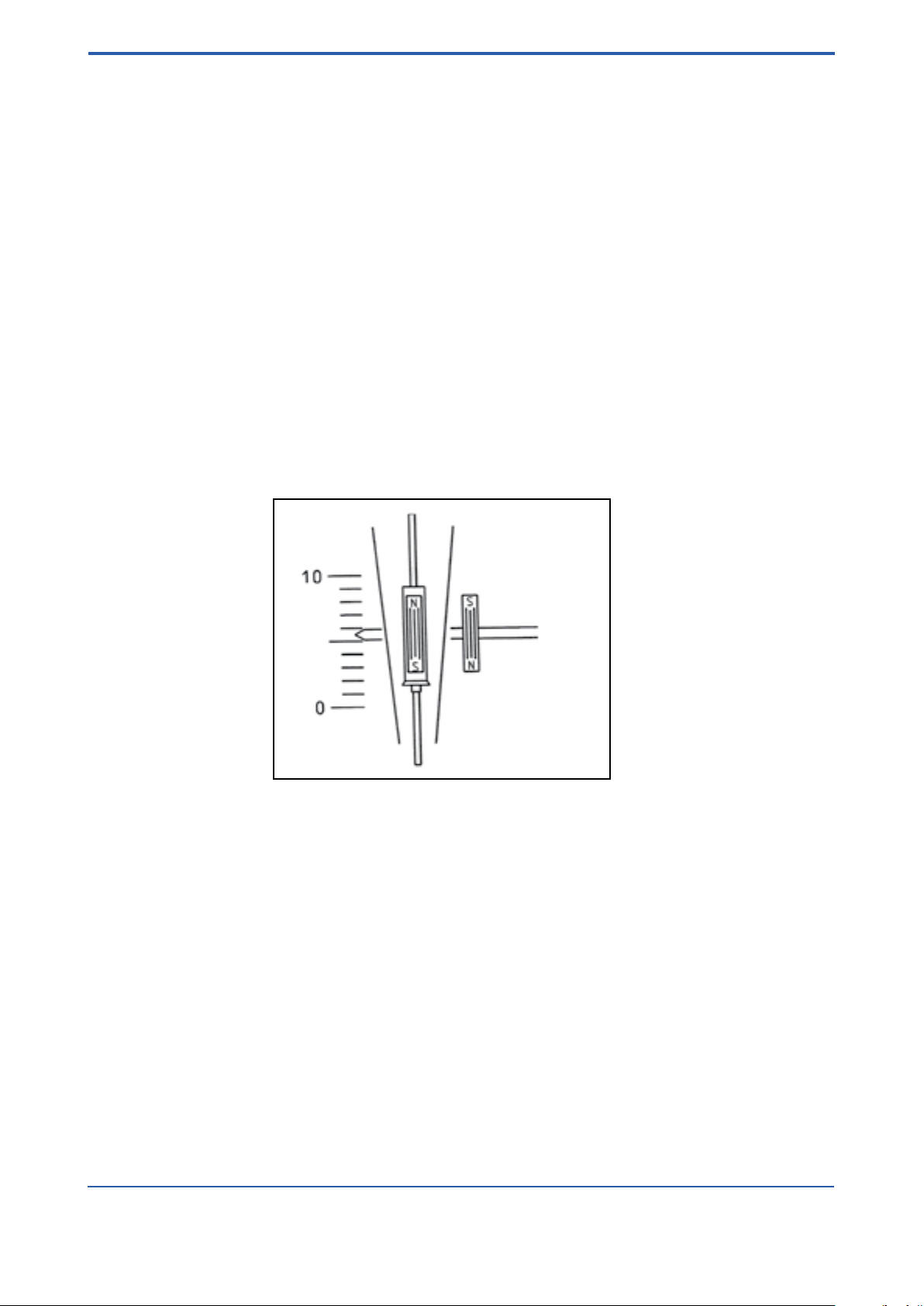
1.5 Principle of measurement
The RAMC is a Variable Area Flow Meter for volume and mass measurements of gases and liquids.
A oat, whose movement is nearly independent of viscosity is guided concentrically in a specially shaped cone.
The position of the oat is transferred magnetically to the indicator, which shows the measurement values by a
pointer on a scale. The indicator can be equipped with limit switches and an electronic transmitter.
Fig. 1-1
All units are calibrated with water by the manufacturer. By adjusting the calibration values to the measured
substance’s state of aggregation (density, viscosity), the ow rate scale for each measuring tube can be
determined.
Indication units can be exchanged without impairment of precision. However, the scale for the tube must be
mounted on the new indicator (and in case of an electronic transmitter the calibration EEPROM, too).
IM 01R01B02-00E-E 14th edition January 20, 2017 -00
All Rights Reserved. Copyright © 2003, Rota Yokogawa
Page 13
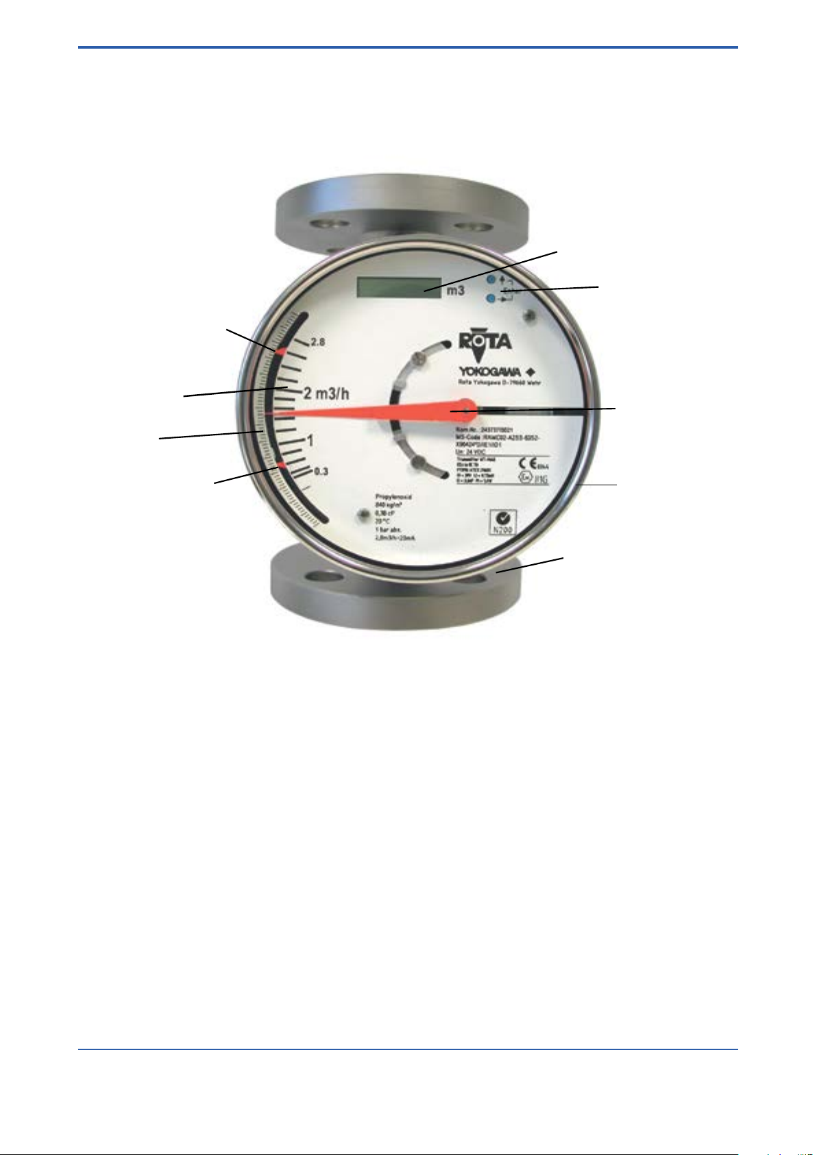
1.6 Overview
Digital display
Operation keys
Pointer
Measuring tube
with flanges
Indicator
Flow scale
Limit switch MIN
Limit switch MAX
mm- scale
<1. INTRODUCTION>
1-5
Fig. 1-2
Explanations of specications on anges
- type of ange e.g. DIN
- size of ange e.g. DN15
- Pressure range of ange and measuring tube e.g. PN40
- Material of wetted parts e.g. 1.4404
- Manufacturing code of ange manufacturer
- Lot. No.
All Rights Reserved. Copyright © 2003, Rota Yokogawa
IM 01R01B02-00E-E 14th edition January 20, 2017 -00
Page 14
1-6
Tag No.: FIT...abcdefg
1.1 bar abs.
1m3/h = 20mA
1 mPas
20 Grad C
Liquide
1.1 t/m
3
E90244*D/B0/CP/K3
MS-Code: RAMC01-D4SS-43S0-
UN: 230VAC 50/60Hz 8VA
Kom.Nr.: 200000/001
Rota Yokogawa D-79660 Wehr
Transmitter WT-MAG
PTB96 ATEX 2160X
Ci = 4,16nF Ii = 101mA
PTB99 ATEX 2219X
see certificate for data
Limit Switch SC3,5-N0
Ui = 30V Li = 0,15mH Pi = 1,4W
EEx ia IIC T6
EEx ia IIC T6
II2G
0344
II2G
Enter
F11.EPS
0.1
0.5
m /h
1.0
3
3
m
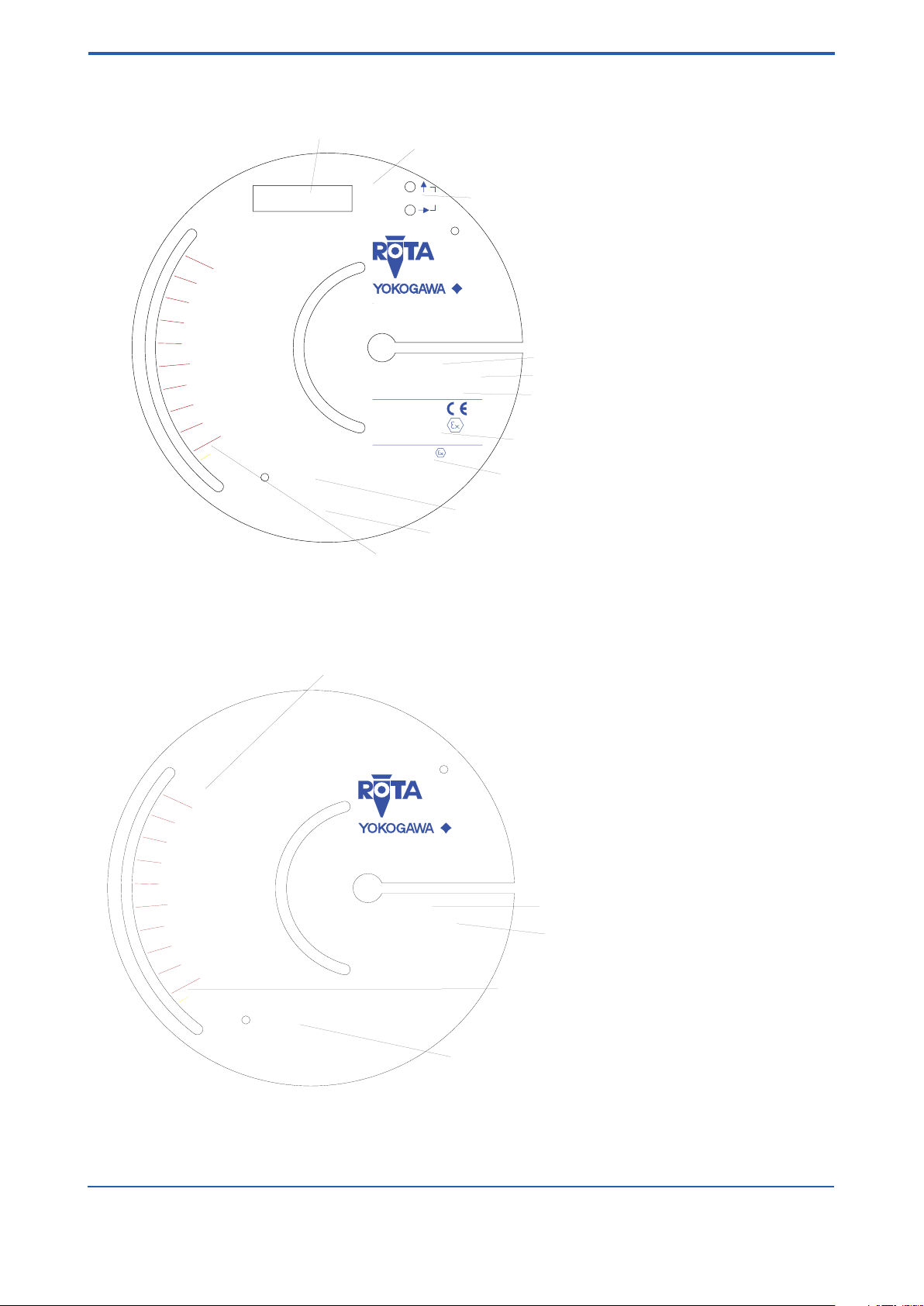
Digital Display
Engineering unit for digital display
Operation keys
Commisioning No.
Model code
Power supply
Ex-identification transmitter
Ex-identification limit switches (/K_)
Current output scaling
Medium data (fluid properties at process conditions)
Flow scale for specific fluid properties at process conditions
Tag No.: FIT...abcdefg
1.1 bar abs.
1 mPas
20 Grad C
Liquide
1.1 t/m
3
T90NNN*D
MS-Code: RAMC01-D4SS-43S0-
Kom.Nr.: 200000/001
Rota Yokogawa D-79660 Wehr
0.1
0.5
m /h
1.0
3
F12.EPS
Flow scale
Commissioning No.
Model code
Medium data (fluid properties at process conditions)
Flow scale for specific fluid properties
at process conditions
Scale examples
<1. INTRODUCTION>
Fig. 1-3 Scale example for -E / -H / -J -type (electronic transmitter)
Fig. 1-4 Scale example for -T -type
IM 01R01B02-00E-E 14th edition January 20, 2017 -00
All Rights Reserved. Copyright © 2003, Rota Yokogawa
Page 15

<2. PRECAUTIONS>
2. Precautions
2.1 Transportation and storage
Before transporting the unit, it is recommended to x the oat with a card-board strip in the same way as
when shipped from factory. Prevent foreign objects from entering the tube (e.g. by covering openings).
To protect the unit and especially the tube’s interior from soiling, store it only at clean and dry locations
2.2 Installation
Ambient temperature and humidity of the installation location must not exceed the specied ranges. Avoid
locations in corrosive environments. If such environments are unavoidable, ensure sufficient ventilation.
Although the RAMC features a very solid construction, the instrument should not be exposed to strong
vibration or impact stress.
Please note that the RAMC’s magnetic sensing system can be inuenced by external inhomogeneous
magnetic elds (such as solenoid valves). Alternating magnetic elds (≥ 10 Hz) as well as homogeneous,
static magnetic elds (in the area of the RAMC), like the geomagnetic eld have no inuence. Asymmetric
ferromagnetic bodies of considerable mass (e.g. steel girders) should be kept at a distance of at least 250 mm
from the RAMC.
To avoid interference, the distance between two adjacent RAMC must be at least 300 mm.
2-1
2.3 Pipe connections
Ensure that the bolts of the anges are tightened properly and that the gaskets are tight.
Do not expose the unit to pressures higher than the indicated maximum operating pressure (refer to
specications).
While the system is pressurized the ange bolts must not be tightened or loosened.
All Rights Reserved. Copyright © 2003, Rota Yokogawa
IM 01R01B02-00E-E 14th edition January 20, 2017 -00
Page 16

2-2
<2. PRECAUTIONS>
Blank Page
IM 01R01B02-00E-E 14th edition January 20, 2017 -00
All Rights Reserved. Copyright © 2003, Rota Yokogawa
Page 17

<3. INSTALLATION>
3-1
3. Installation
3.1 Installation in the pipeline
Be sure to remove the transport lock card-board strip from the measuring tube. Check that no cardboard
remains in the tube.
The RAMC ow rate meter must be installed in a vertical pipeline, in which the medium ows upwards.
vertical position has to be checked at the outer edge of the anges. Bigger nominal diameters (DN80/DN100)
require straight pipe sections of at least 5D in front and behind the RAMC.
The nominal diameter of the RAMC should correspond to the nominal diameter of the pipeline.
To avoid stress in the connecting pipes, the connecting anges must be aligned in parallel and axial direction.
Bolts and gaskets have to be selected according to the maximum operating pressure, the temperature range
and corrosion conditions. Center gaskets and tighten nuts with a torque appropriate for the pressure range.
If contamination or soiling of the RAMC is to be expected, a bypass should be installed to allow the removal of
the instrument without interruption of the ow.
Please read also chapter 2.2. For further instructions on installation please refer to VDI/VDE3513.
Tightening of the ange threads for RAMC with PTFE- liner with the following torques:
Nominal Size Bolts Maximum Torque
EN 1092-1 ASME B 16.5 EN 1092-1 ASME EN 1092-1 ASME 150 lbs
DN PN Inches lbs 150 lbs 300 lbs Nm ft*lbf Nm ft*lbf
15 40 ½ 150/300 4 x M12 4 x ½´´ 4 x ½´´ 9.8 7. 1 5.2 3.8
25 40 1 150/300 4 x M12 4 x ½´´ 4 x ½´´ 21 15 10 7.2
50 40 2 150/300 4 x M16 4 x 5/8´´ 8 x 5/8´´ 57 41 41 30
80 16 3 150/300 4 x M16 4 x 5/8´´ 8 x ¾´´ 47 34 70 51
100 16 4 150/300 4 x M16 8 x 5/8´´ 8 x ¾´´ 67 48 50 36
The
All Rights Reserved. Copyright © 2003, Rota Yokogawa
IM 01R01B02-00E-E 14th edition January 20, 2017 -00
Page 18
3-2
<3. INSTALLATION>
3.2 Wiring of electronic transmitter (-E, -H, -J) and limit
switches (/K
Please regard the drawings on the following pages.
On the rear of the RAMC are two cable glands for round cables with a diameter of 6 to 9 mm (not for Ex-d-type
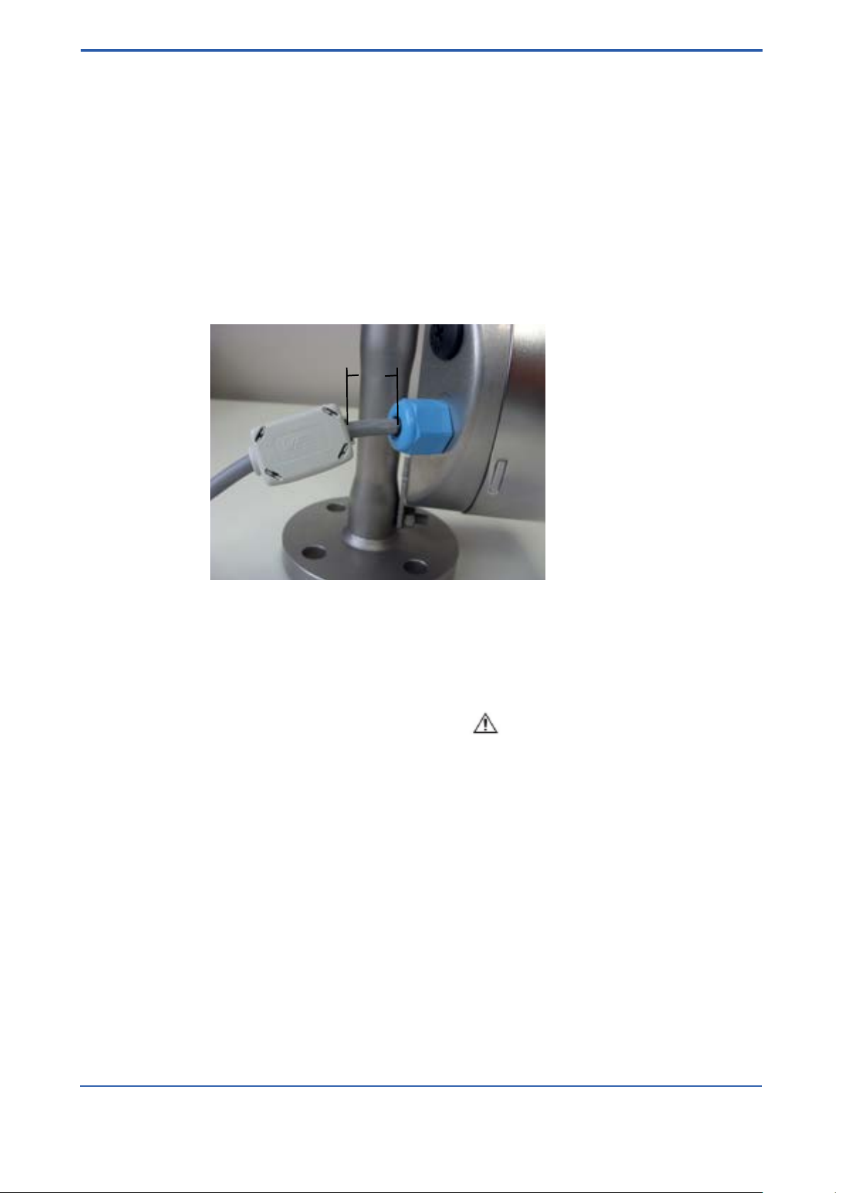
option /F1). Unused glands must be closed with a blind plug M16x1.5.
For wiring of RAMC with option/F1 see chapter 10.10.2, 10.11.2, 10.14.2.
Wires should not be bent directly at terminal screws. Do not expose wires to mechanical pressure. Wires must be
arranged according to common installation rules, especially signal and power lines must not be bundled together.
Cables should not be bend directly after the cable gland. Do not x cable at the measuring tube.
The RAMC terminals accept wires with a maximum sectional area of 1.5 mm2.
The attached ferrite core must be mounted on the cable as shown on the below picture. Distance "L" < 2 cm.
)
L
Measuring and indicating instruments, connected in series to the output of the electronic transmitter, must not
exceed a load impedance of R
2- or 3-wire units are connected to the terminals marked “+”, “-” and “A” of the power connector.
For 2-wire instruments the terminals “-” and “A” have to be shorted with a jumper. Take care not to loose that
jumper when mounting wires.
Wiring inside the case should be kept as short as possible to avoid that moving parts are blocked.
Attention: Hints for Unit Safety (according DIN EN 61010-1)
- Do not connect cables outdoors in wet weather in order to prevent damage from condensation and to protect
the insulation, e.g. inside the terminal box of the owmeter.
- Heed the nominal voltage indicated on the scale.
- Use the cables which fulll specication and check before wiring.
- The electrical connections have to be executed according to VDE0100 “Errichten von Starkstromanlagen
mit Nennspannungen bis 1000 V” (Installation of high current assemblies with nominal voltages of up to 1000 V)
or equivalent national regulations.
- For units with a nominal voltage of 115 V or 230 V the correspondingly marked terminal has to be
connected to protective earth (PE).
- Units with a nominal voltage of 24 V may only be connected to a protected low voltage circuit (SELV-E
according to VDE0100/VDE 0106 or IEC 364/IEC 536).
- The RAMC indicator housing must be grounded to ensure electromagnetic interference protection.
This can be done by grounding the pipeline.
- Once all wiring is complete, check the connections before applying power to the instrument. Improper
arrangements or wiring may cause a unit malfunction or damage.
- This unit does not include a power switch. Therefore, a switch has to be prepared at the installation
location in the vicinity of the unit. The switch should be marked as the power separation switch for the
RAMC.
= (U - 13.5 V) / 20 mA — for 2-/3-wire RAMC or 500 Ω for 4-wire RAMC.
L
IM 01R01B02-00E-E 14th edition January 20, 2017 -00
All Rights Reserved. Copyright © 2003, Rota Yokogawa
Page 19
<3. INSTALLATION>
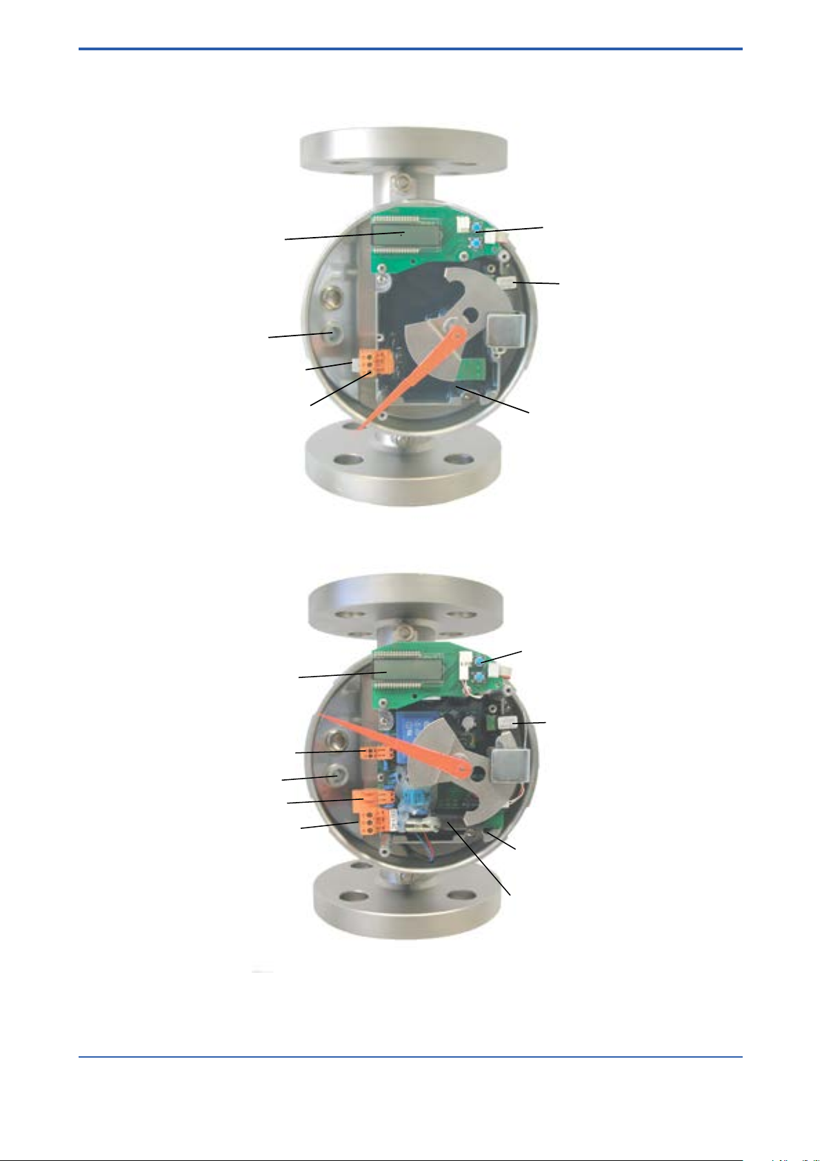
Operation keys
Calibration-EEPROM
Angle transmitter
Digital display
Cable gland
Power supply plug
Plug for 2-wire connection
Calibration-EEPROM
Pulse output (option /CP)
3-3
Fig. 3-1 2-wire unit
Digital display
Cable gland
Current output
Mains connector
Operation keys
Angle transmitter
Power supply circuit
Fig. 3-2 4-wire unit
All Rights Reserved. Copyright © 2003, Rota Yokogawa
IM 01R01B02-00E-E 14th edition January 20, 2017 -00
Page 20
3-4
15
4
6
3
1
14
12
10
11
8
7
9
U
F
G
RAMC
A
Power supply U
Mains 230V AC
KFA6-SR2-Ex2.W
Option: /W2B
Transmitter Relay
Limit MIN
Limit MAX
Option / Kn
Rotameter
4-20mA
Max
Min
12
11
10
9
Limit switches
EN 60947-5-6 (Namur)
One channel connection like limit MAX
4-20mA
RL
-
+
-
+
-
+
-
+
~ ~
+
-
+
-
Power supply U / V RL /
W
13.5V ... 30V < (U-13.5V) / 20mA
F1.EPS
15
4
6
3
1
14
12
10
11
8
7
9
U
F
G
RAMC
A
Power supply U
Mains 230V AC
KFA6-SR2-Ex2.W
Option: /W2B
Transmitter Relay
Limit MIN
Limit MAX
Option / Kn
Rotameter
Max
Min
12
11
10
9
Limit switches
EN 60947-5-6 (Namur)
One channel connection like limit MAX
0/4 - 20mA
RL
-
+
-
+
-
+
-
+
~ ~
+
-
+
-
Power supply U / V RL /
W
13.5V ... 30V < (U-13.5V) / 20mA
F2.EPS
<3. INSTALLATION>
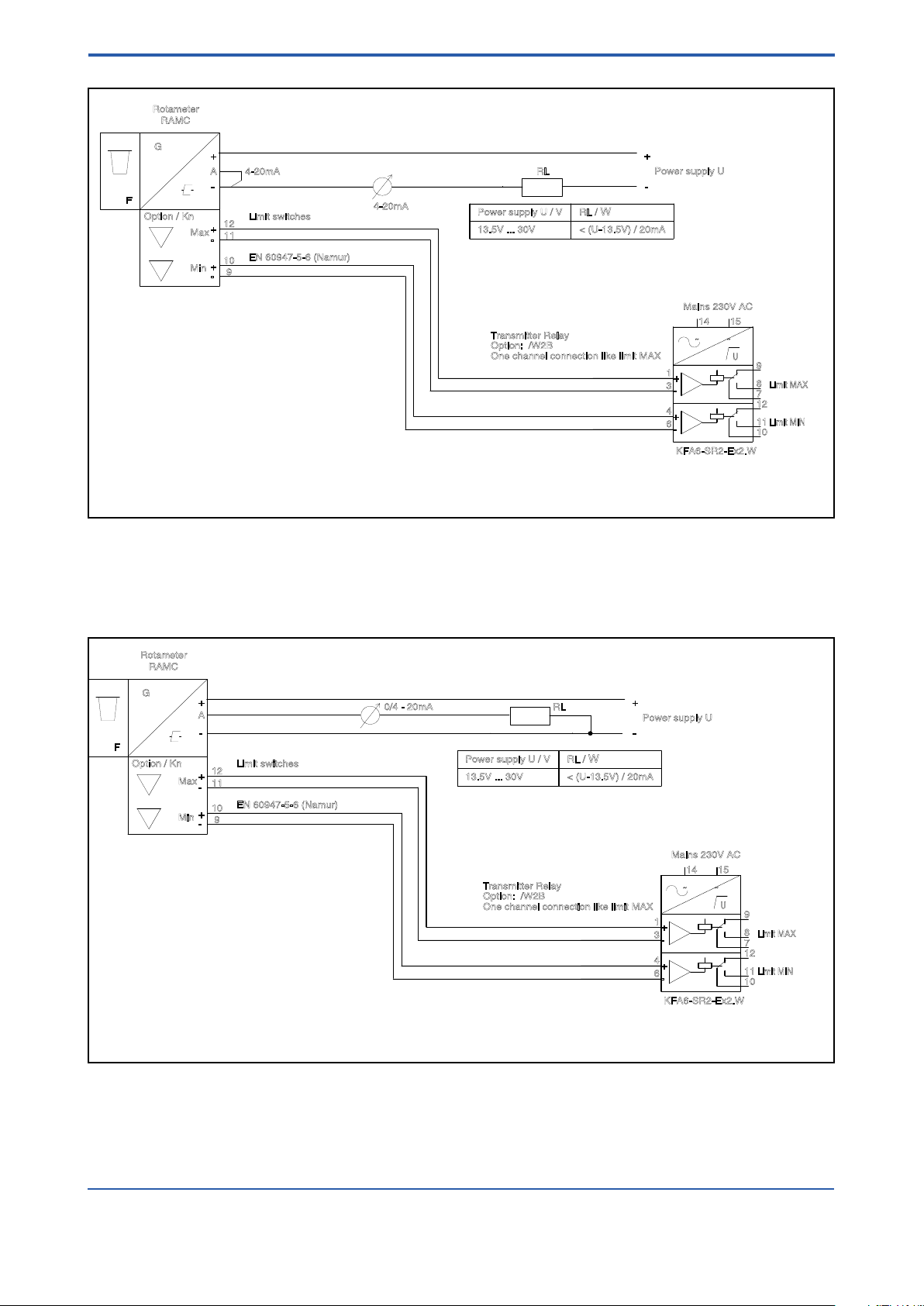
Fig. 3-3 RAMC 2-wire unit with limit switches and transmitter relay
Fig. 3-4 RAMC 3-wire unit with limit switches and transmitter relay
IM 01R01B02-00E-E 14th edition January 20, 2017 -00
All Rights Reserved. Copyright © 2003, Rota Yokogawa
Page 21
F
G
RAMC
230 / 115 V AC
4
Power supply
Output 0/4-20mA
R < 500 Ω
L
Rotameter
PE--
5
7
6
Pulse output
Umax = 30V ; Imax = 100mA
-
+
-
+
+
-
F3.EPS
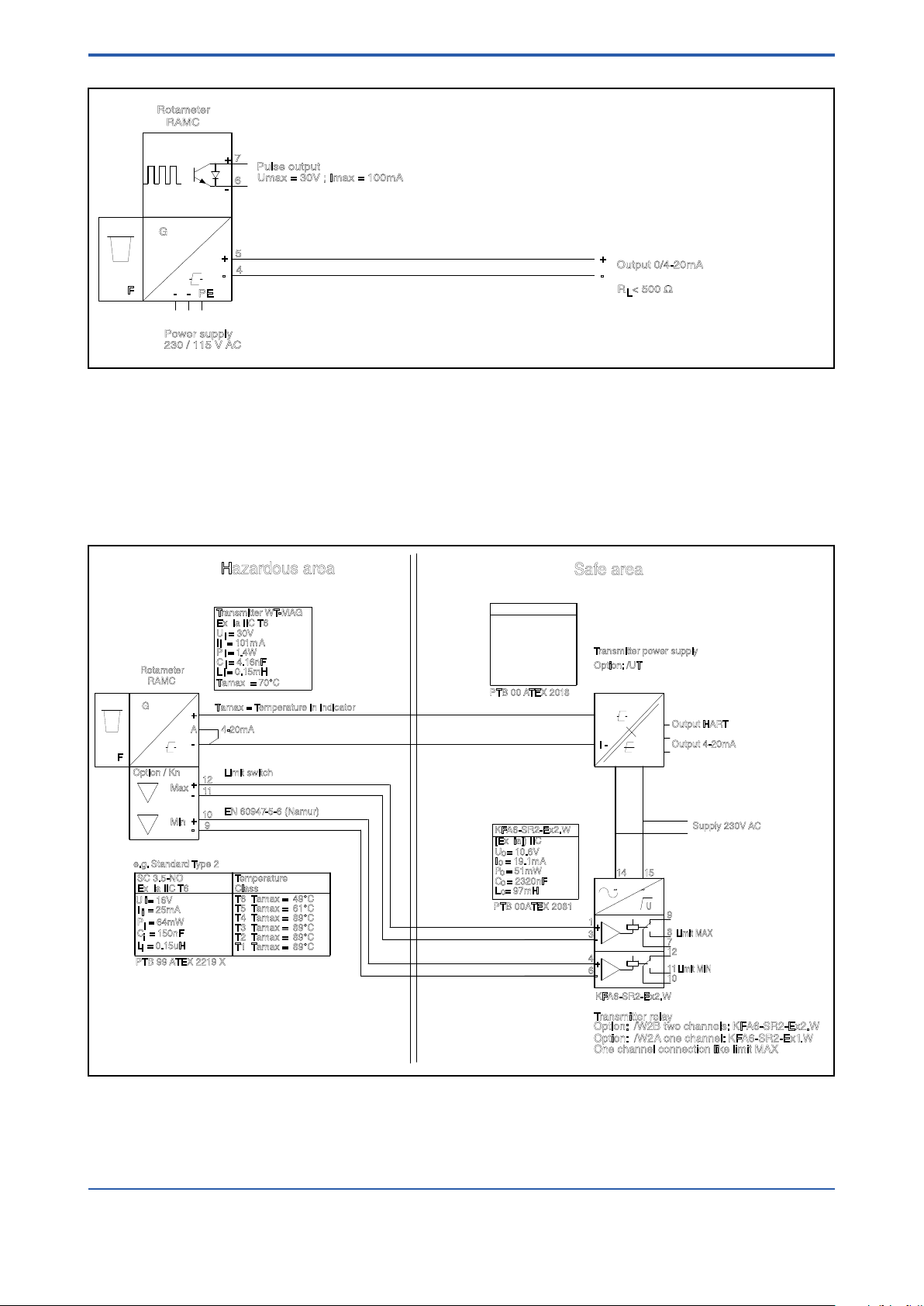
Fig. 3-5 RAMC 4-wire unit with pulse output
15
4
6
3
1
14
12
10
11
8
7
9
12
11
10
9
I -
I +
L/+N/-
O -
O+
Output 4-20mA
O+H
Output HART
U
F
G
RAMC
A
Supply 230V AC
KFA6-SR2-Ex2.W
Option: /W2B two channels: KFA6-SR2-Ex2.W
Transmitter relay
Limit MIN
Limit MAX
Option / Kn
Rotameter
4-20mA
Max
Min
Limit switch
EN 60947-5-6 (Namur)
One channel connection like limit MAX
I = 101mA
P = 1.4W
C = 4.16nF
U = 30V
L = 0.15mH
Transmitter WT-MAG
Ex ia IIC T6
Gb
PTB 12 ATEX 2003
Tamax = 70°C
Tamax = Temperature in indicator
C = 150nF
Ex ia IIC T6
L
= 0.15uH
SC 3.5-NO
P = 64mW
I = 25mA
U = 16V
Temperature
T4 Tamax = 89°C
T3 Tamax = 89°C
T2 Tamax = 89°C
T1 Tamax = 89°C
Class
T5 Tamax = 61°C
T6 Tamax = 49°C
PTB 99 ATEX 2219 X
PTB 00 ATEX 2018
Transmitter power supply
Option: /UT
Option: /W2A one channel: KF A6-SR2-Ex1.W
C = 2320nF
I = 19.1mA
P = 51mW
U = 10.6V
L = 97mH
PTB 00ATEX 2081
[Ex ia]) IIC
KFA6-SR2-Ex2.W
RN221N-B1
RN221N-B1
Tamax = 50°C
C = 86nF
L = 5.2mH
U = 27.3V
P = 0.597W
[Ex ia] IIC
I = 87.6mA
o
o
o
o
o
e.g. Standard Type 2
-
+
-
+
-
+
~ ~
+
-
+
-
i
i
i
i
i
i
i
i
i
o
o
o
o
o
F5.EPS
i
Hazardous area
Safe area
<3. INSTALLATION>
3-5
Fig. 3-6 Ex-version acc. to ATEX (Option /KS1 and /KS2) : RAMC 2-wire unit with power supply,
limit switches and transmitter relay
All Rights Reserved. Copyright © 2003, Rota Yokogawa
IM 01R01B02-00E-E 14th edition January 20, 2017 -00
Page 22
3-6
15
4
6
3
1
14
12
10
11
8
7
9
U
F
G
RAMC
A
Power supply U
Mains 230V AC
KFA6-SR2-Ex2.W
Option: /W2B
Transmitter Relay
Limit MIN
Limit MAX
Option / Kn
Rotameter
4-20mA
Max
Min
12
11
10
9
Limit switches
EN 60947-5-6 (Namur)
One channel connection like limit MAX
4-20mA
RL
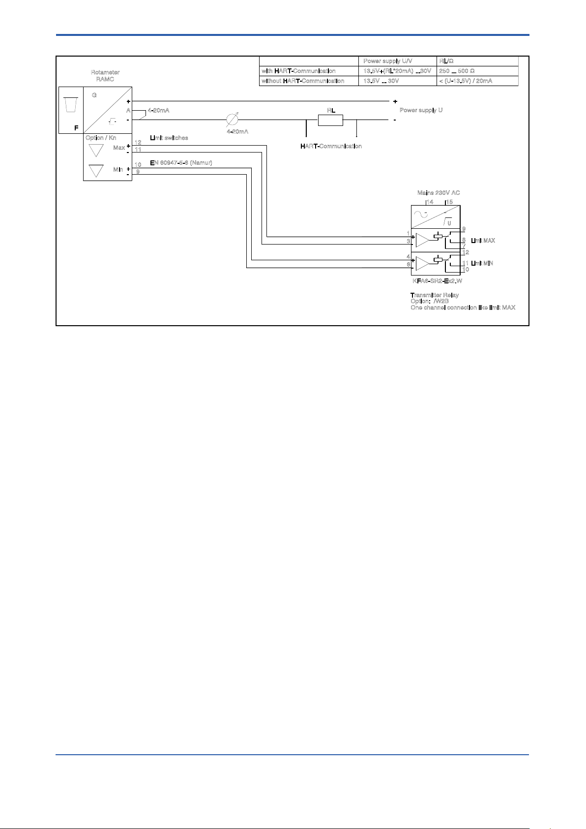
HART-Communication
with HART-Communication
without HART-Communication
Power supply U/V RL/Ω
13.5V+(RL*20mA) ...30V
13.5V ... 30V < (U-13.5V) / 20mA
250 ... 500 Ω
-
+
-
+
-
+
-
+
~ ~
+
-
+
-
F4.EPS
<3. INSTALLATION>
Fig. 3-7 RAMC 2-wire unit with HART-communication, with limit switches and transmitter relay
IM 01R01B02-00E-E 14th edition January 20, 2017 -00
All Rights Reserved. Copyright © 2003, Rota Yokogawa
Page 23

<4. START OF OPERATION>
4-1
4. Start of operation
4.1 Hints on ow rate measurement
The measured uid should neither consist of a multi-phase mixture nor contain ferrite ingredients or large solid
mass particles.
The RAMC scale is adjusted to the state of operation/aggregation of the measured uid by the manufacturer. If
the state of operation changes, it might become necessary to establish a new scale. This depends on several
factors:
- If the RAMC is operated in the given viscosity independent range, only the density of the oat as well as the
operational density of the previous and new substance have to be considered. In case the operational
density only changes marginally (≤ 0.5 %), the present scale can be used.
- If the RAMC is operated outside the given viscosity independent range, the viscosities at the previous and new
state of operation as well as the mass and diameter of the oat have to be taken into account.
4.2 Pulsation and pressure shock
Pressure shock waves and pulsating ow inuence measurement signicantly or can destroy the meter. Surge
conditions should be avoided. (open valves slowly, raise operating pressure slowly)
If oat bouncing occurs in gases increase the line pressure until the phenomena stops. If this is not possible
provide the oat with a damper. A damping kit is available as spare part.
4.3 Start of operation of electronic transmitter
Ensure that the device has been connected correctly according to section 3-2 and that the used power supply
meets the requirements indicated on the scale.
Switch on the power supply.
The digital display gives the totalizer value in the measuring unit, indicated on the right side of the display.
The RAMC is now ready for operation.
Unit graduation, measuring unit, damping, etc. can be adjusted by an operating menu (refer to section 6.2). In
case of an error, the bars beneath the 8 digits of the display will ash. The corresponding error message can
be checked using the operating menu and then taking the appropriate counter measures (refer to section
6-2-8 “Error Messages”).
The transmitter has been prepared and calibrated according to the model code as a 2-, 3- or 4-wire unit.
In 2-wire units, a jumper connects “A” and “-”. When switching from a 2- to a 3-wire conguration, this jumper
should be removed. The current output should then be adjusted as explained in section 6-2-6.
When changing from a 3- to 2-wire conguration, the jumper should be set in place, and the current output
has to be adjusted according to section 6-2-6.
All Rights Reserved. Copyright © 2003, Rota Yokogawa
IM 01R01B02-00E-E 14th edition January 20, 2017 -00
Page 24

4-2
<4. START OF OPERATION>
Blank Page
IM 01R01B02-00E-E 14th edition January 20, 2017 -00
All Rights Reserved. Copyright © 2003, Rota Yokogawa
Page 25
<5. LIMIT SWITCHES OPTION /K>
5-1
5. Limit switches (Option /K)
The optional limit switches are available as maximum or minimum type switches. They are proximity switches
according to EN 60947-5-6 (NAMUR). Maximum two switches can be installed. The option (/W) includes the
respective transmitter relay.
These switches have been specied for hazardous area. However, the transmitter relay must be installed
in safe area.
The limit switches are connected to the transmitter relays as indicated in chapter 3.2.
The terminals for the limit switches are on a small board on top of the transmitter case.
Use of 2 standard limit switches (option /K3):
The MIN-MIN and MAX-MAX functions have been integrated at the factory as MIN-MAX switches in the RAMC.
The MIN-MIN or MAX-MAX function is set by adjusting the switching direction of the transmitter relay. The
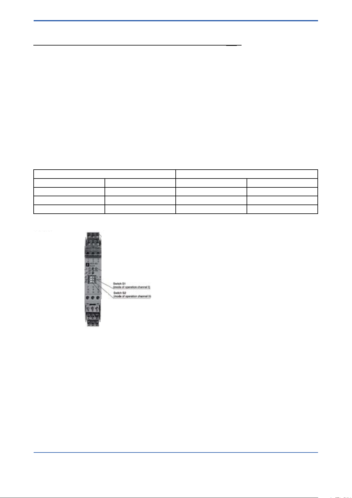
concerning 2- channel transmitter relays are:
Option /W1B: KFA5-SR2-Ex2.W
Option /W2B: KFA6-SR2-Ex2.W
Option /W4B: KFD2-SR2-Ex2.W
The following table shows the assignment:
Function Switching direction of transmitter relay *
Channel 1 Channel 2 Channel 1 Channel 2
MIN MAX S1 position I S2 position I
MIN MIN S1 position I S2 position II (ON)
MAX MAX S1 position II (ON) S2 position I
* see following gure for S1 and S2 on transmitter relay.
Use of Fail Safe limit switches (option /K6.../K10):
For Fail Safe application only 1- channel transmitter relays are available.
Option /W2E: KHA6-SH-Ex1.W
Option /W2F: 2 x KHA6-SH-Ex1.W
Option /W4E: KFD2-SH-Ex1.W
Option /W4F: 2 x KFD2-SH-Ex1.W
If other transmitter relays are used as the above mentioned types, the transmitter relay has to be applied
as protection technology to ensure functional safety.
Please notice chapter 9.3 "Standard specications".
For questions regarding protection technology, please consult your YOKOGAWA service center.
All Rights Reserved. Copyright © 2003, Rota Yokogawa
IM 01R01B02-00E-E 14th edition January 20, 2017-00
Page 26

5-2
<5. LIMIT SWITCHES OPTION /K>
Blank Page
IM 01R01B02-00E-E 14th edition January 20, 2017 -00
All Rights Reserved. Copyright © 2003, Rota Yokogawa
Page 27
<6. ELECTRONIC TRANSMITTER (-E)>
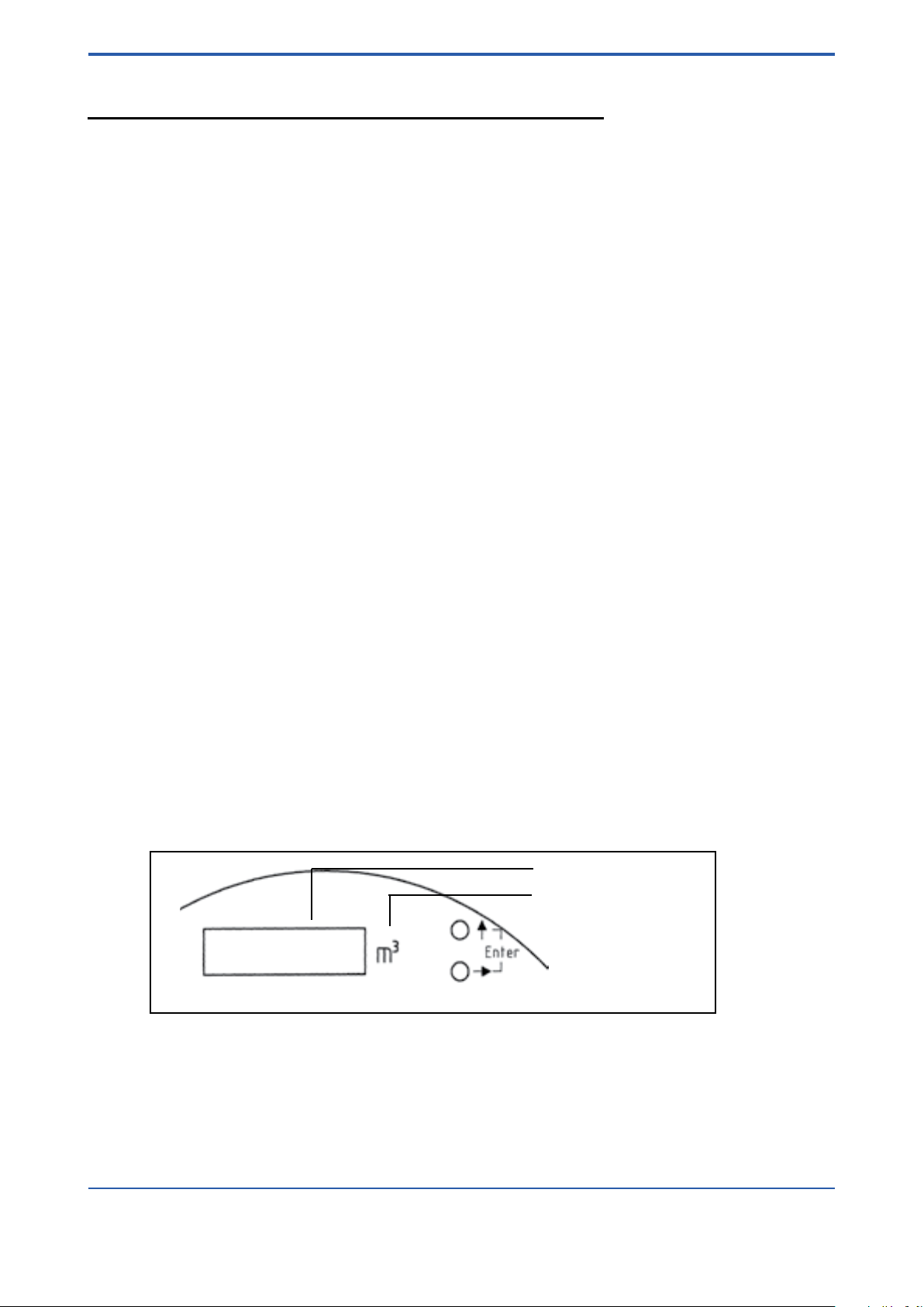
F61.EPS
Digital display
Engineering unit of the display
Operation keys
6-1
6. Electronic Transmitter (-E)
6.1 Operation principle
The position of the oat is magnetically transferred to a magnetic follow up system. The position angle of this
magnetic rocker is detected by magnet sensors. A micro controller determines the angle by means of a
combining reference value table in the memory and calculates the ow rate by the angle with calibration and
operation parameters the calibration EEPROM. The ow rate is given as a current, either 0-20 mA or 4-20 mA,
and, in addition, indicated on the digital display (refer also to section 6-2). The electronic transmitters have been
electronically adjusted before shipping and, therefore, are mutually exchangeable.
Calibration data of the metering tube as well as customer specic data are entered into a calibration EEPROM,
inserted on the board. This calibration EEPROM and the indication scale are assigned to the respective
metering tube.
When replacing an indicator (e.g. because of a defect) the scale and calibration EEPROM of the old unit have
to be inserted in the new unit. Then, no calibrations or adjustments are necessary.
If an indicator with electronic transmitters is installed to a new metering tube, the calibration EEPROM of that
tube has to be inserted into the transmitter and the indicator scale for that particular tube has to be mounted.
A change in the uid data (e.g. specic gravity, pressure, etc.) requires the preparation and mounting of
a new calibration EEPROM and scale.
Normally the range of the current output is equal to the rounded measuring range of the tube (end value on
scale). The customer can position the 20 mA point between 60% and 100% of the end value on scale. The set
of the 20 mA point is shown on the scale (refer to Fig. 1-4). The ow cut off is positioned at 5 % of the end value.
Below 5 % ow the current output shows 0 mA (4 mA).
6.2 Parameter setting
The displays allows indication of various parameters:
• Flow rate (8 mass or volume units in combination with 4 time units)
• Counter (8 mass or volume units)
• Flow rate indication in percent
• Special functions
• Setting of different damping times
• Switching of current output 0-20 mA / 4-20 mA or vice versa
• Indication of error messages
• Manual adjustment
• Service functions
• Detection of oat blockage
The setting of these parameters is done by two buttons.
Fig. 6-1 Operation keys
All Rights Reserved. Copyright © 2003, Rota Yokogawa
IM 01R01B02-00E-E 14th edition January 20, 2017 -00
Page 28

6-2
<6. ELECTRONIC TRANSMITTER (-E)>
The buttons access three functions:
- upper button ( ↑ ) : Exit setting mode
- lower button ( → ) : Scroll through menu/selection of parameters
- both buttons ( ↑ + → ) = Enter : Entering parameters/selecting setting mode
If no button is pressed for one minute while the operating menu is active, the indication reverts to the
measuring indication. This does not apply to subfunctions F32, F33, F52, F63.
For indication of volume or mass values at maximum 6 digits in front of the decimal point and 7 decimals are
used. This format allows an indication range for ow rates from 0.0000001 unit/time to 106000 unit/time. Flow
rate values exceeding 106000 are shown as ‘————’ on the display. In this case the next bigger ow rate unit
(next smaller time unit) has to be selected.
For the indication of totalizers values 8 digits are used at maximum of which 7 digits can be assigned for
decimal values. The decimal point setting is determined by selecting the unit. Therefore, possible totalizer
offsets are:
Unit *1
Unit *1/10
Unit *1/100
The totalizer counts up to 99999999 or 9999999.9 or 999999.99 and is reset to zero.
The next page shows the operating menu.
The following describes selection and execution of functions.
Menu:
Indication meas .val F1- : Indication F11: Selection F11-1 : Flow rate
F11-2 : Totalizer
F11-3 : %
F11-4 : Temperature
Euro / US
F12 : Flow rate unit F12-1 : m³ / m³
F12-2 : l / acf
F12-3 : Nm³ / Nm³
F12-4 : NL / scf
F12-5 : t / ton
F12-6 : kg / kg
F12-7 : scf / lb
F12-8 : gal / usg
Euro / US
F13 : Time unit F13-1 : h / h
F13-2 : min / min
F13-3 : s / s
F13-4 : day / day
F14 : Reset Totalizer F14-1 : Execute
F2- : Damping F21 : Selection F21 0 : 0 s
IM 01R01B02-00E-E 14th edition January 20, 2017 -00
F15 : Temperature unit F15-1 : degC
F15-2 : DegF
F21 1 : 1 s
F21 5 : 5 s
F21 10 : 10 s
All Rights Reserved. Copyright © 2003, Rota Yokogawa
Page 29
<6. ELECTRONIC TRANSMITTER (-E)>
F3- : Output F31 : Selection F31 0-20 : 0-20 mA
F31 4-20 : 4-20 mA
F32 : Offset adjustment F32 00
F33 : Span adjustment F33 00
F34 : Pulse output *) F34-1 : not active
F34-2 : last digit
F34-3 : last but one digit
F4- : Error messages F41 : Indication F41 Enn
F5- : Manual adjustment F51 : On/Off F51-1 : off
F51-2 : on
F52 : Adjustment table F52 5 : 5 % point
F52 15 : 15 % point
F52 25 : 25 % point
F52 35 : 35 % point
F52 45 : 45 % point
F52 55 : 55 % point
F52 65 : 65 % point
F52 75 : 75 % point
F52 85 : 85 % point
F52 95 : 95 % point
F52 105 : 105 % point
6-3
F6- : Service F61 : Revision indicatior H.. F..
F62 : EEPROM revision A.. C..
F63 : Current output test F63 04 : 0 or 4 mA
F63 20 : 20 mA
F64 : Calibration table F64-1 : Standard
F64-2 : Remote version
F65 : Master Reset F65-1 : Execute
F7- : Float Block. Ind. F71 : Off/On F71-1 : Off/On
F71-2 : On/Off
F72 : Lower limit F72-1 : 5 % of Qmax
F72-2 : 15 % of Qmax
F72-3 : 30 % of Qmax
F73 : Supervision time F73-1 : 5 Minutes
F73-2 : 15 Minutes
F74 : Autozero F74-1 : Execute
Bold type = Factory Pre-setting
*) Option /CP
All Rights Reserved. Copyright © 2003, Rota Yokogawa
IM 01R01B02-00E-E 14th edition January 20, 2017 -00
Page 30

6-4
<6. ELECTRONIC TRANSMITTER (-E)>
6.2.1 Selection of indication function (F11)
The function F11 selects the display’s indication function.
The following indications can be set: ow rate, totalizer, % value or temperature.
At the factory the display is preset to totalizer indication.
Description Selection Key Indication
Display mode
Change to setting mode Enter
Setting function
Selection
or
or
or
Back to display mode
Note: If you press “↑” instead of “Enter”, you can return from the selected point to the previous menu without
activating the displayed parameter.
Flow rate
Totalizer
%
Temperature
Enter
Enter
Enter
→
Enter
2 x →
Enter
3 x →
Enter
↑
↑
F1F11
F11 -1
F11
F11 -2
F11
F11 -3
F11
F11 -4
F11
F1Display mode
When selecting “Flow rate” the measuring unit is set with function F12 and F13. When selecting “Totalizer” the
measuring unit is set with F12. If % indication is selected, F12 and F13 have no effect. The internal totalizer is
updated, if “Flow rate” or “Counter” is selected. In case of setting to “%” the internal counter is not updated
and keeps its previous value.
If "Temperature" is selected the unit can be set by function F15. The indicated value is the temperature in the
indication unit.
After changing the indicating function and measuring units the corresponding measuring unit label should be
xed on the right side next to the display.
IM 01R01B02-00E-E 14th edition January 20, 2017 -00
All Rights Reserved. Copyright © 2003, Rota Yokogawa
Page 31

<6. ELECTRONIC TRANSMITTER (-E)>
6-5
6.2.2 Setting the unit (F12 / F13)
When ordering the transmitter two sets of metering units are available. It is not possible to switch between them.
These two sets comprise the following metering units:
European unit set, Standard
Standard Description Unit Menu / Index
Flow rate unit SI
SI
SI
SI
SI
SI
---
---
Time unit SI
SI
SI
---
Cubic meter
Liter
Norm cubic meter
(0 °C; 1 Atm.abs = 1.013 bar)
Norm Liter
Ton
Kilogram
Standard cubic feet
(60 °F; 1 Atm.abs = 14,69 psi)
Gallon (imperial, UK)
Hour
Minute
Second
Day
m³
l
Nm³
Nl
t
kg
scf
gal
h
min
s
d
-1
-2
-3
-4
-5
-6
-7
-8
-1
-2
-3
-4
US unit set, Option /A12
Standard Description Unit Menu / Index
Flow rate unit SI
--SI
---
--SI
---
---
Time unit SI
SI
SI
---
Cubic meter
Actual cubic feet
Norm cubic meter
(0 °C; 1 Atm.abs = 1.013 bar)
Standard cubic feet
(60 °F; 1 Atm.abs = 14.69 psi)
Long ton
Kilogram
Pound
Gallon (US)
Hour
Minute
Second
Day
m³
acf
Nm³
scft
ton
kg
lb
usg
h
min
s
d
-1
-2
-3
-4
-5
-6
-7
-8
-1
-2
-3
-4
All Rights Reserved. Copyright © 2003, Rota Yokogawa
IM 01R01B02-00E-E 14th edition January 20, 2017 -00
Page 32

6-6
<6. ELECTRONIC TRANSMITTER (-E)>
With functions F12 and F13, the measuring unit for displayed value is selected.
F12 selects volume and mass units, while F13 sets the corresponding time unit.
When selecting the indication function “totalizer” the set time unit is not taken into account and only the
selected mass or volume unit is effective. When choosing the “%” indication F12 and F13 have no effect.
The selection of the measuring unit is performed as follows:
Description Selection Key Indication
Display mode
Change to setting mode Enter
Setting
Masse/Volume unit unit set
Euro US
Selection unit
or
m3 m3
l acf
Enter
→
Enter
Enter
→
Enter
or
Nm3 Nm3
2 x →
Enter
or
Nl scf
3 x →
Enter
or
t ton
4 x →
Enter
or
kg kg
5 x →
Enter
or
scf lb
6 x →
Enter
gal usg
7 x →
Enter
Setting
Time unit
Selection time unit
or
h h
min min
→
Enter
Enter
→
Enter
or
s s
2 x →
Enter
or
day day
3 x →
Enter
Back to display mode
↑
↑
F1F11
F12
F12 -1
F12
F12 -2
F12
F12 -3
F12
F12 -4
F12
F12 -5
F12
F12 -6
F12
F12 -7
F12
F12 -8
F12
F13
F13 -1
F13
F13 -2
F13
F13 -3
F13
F13 -4
F13
F1Display mode
Note: If you press “↑" instead of “Enter”, you can return from the selected point to the previous menu
without activating the displayed parameter.
After changing the measuring unit the corresponding measuring unit label should be xed on the right side
next to the display. A sheet with stickers is included.
Attention: When switching the mass/volume unit the totalizer is reset to zero.
When changing the time unit the totalizer value remains unchanged.
IM 01R01B02-00E-E 14th edition January 20, 2017 -00
All Rights Reserved. Copyright © 2003, Rota Yokogawa
Page 33

<6. ELECTRONIC TRANSMITTER (-E)>
6.2.3 Totalizer reset (F14)
Function F14 resets the totalizer to zero.
The counter reset is performed as follows:
Description Selection Key Indication
Display mode
Change to setting mode Enter
Setting mode Enter
3 x →
Enter
Selection Reset Enter F14
Back to display mode
Note: If you press “↑" instead of “Enter”, you can return from the selected point to the previous menu
without activating the displayed parameter.
↑
↑
F1F11
F14
F14 -1
F1Display mode
6.2.4 Selection of temperature unit (F15)
The function F15 sets the unit of temperature indication.
The following indications can be set: degC (Celsius) or degF (Fahrenheit).
At the factory the display is set to degC indication.
The selection of the indication is as follows:
Description Selection Key Indication
Display mode
Change to setting mode Enter
Setting mode Enter
4 x →
Enter
Selection degC
degF
Back to display mode
Enter
→
Enter
↑
↑
F1F11
F15
F15 -1
F15
F15 -2
F15
F1Display mode
6-7
Note: If you press “↑" instead of “Enter”, you can return from the selected point to the previous menu
without activating the displayed parameter.
All Rights Reserved. Copyright © 2003, Rota Yokogawa
IM 01R01B02-00E-E 14th edition January 20, 2017 -00
Page 34

6-8
<6. ELECTRONIC TRANSMITTER (-E)>
6.2.5 Setting of damping (F2-)
Function F21 allows damping the output with a certain time constant (63 % value). Normally the time constant
is set to 1 sec.
The selection of the time constant is as follows:
Description Selection Key Indication
Display mode
Change to setting mode Enter
Setting mode →
Enter
Selection damping
constant
or
or
or
Back to display mode
Note: If you press “↑" instead of “Enter”, you can return from the selected point to the previous menu
without activating the displayed parameter.
0 s
1 s
5 s
10 s
Enter
Enter
→
Enter
2 x →
Enter
3 x →
Enter
↑
↑
F1F2-
F21
F21 0
F21
F21 1
F21
F21 5
F21
F21 10
F21
F2Display mode
6.2.6 Selection / Adjustment 4-20 mA / 0-20 mA (F3-)
Function F3- sets the current output to 4-20 mA or 0-20 mA. In addition, offset and span have to be
readjusted. Offset compensation is for ne tuning the 0 or 4 mA point. Span or range compensation is for
precise adjustment of the 20 mA point.
For compensating the output, an ampere metre (mA) should be connected to the circuit loop. For wiring refer
to the diagrams in chapter 3.
The current output is set according to customer specications at the factory.
Switching the output is executed as follows:
Description Selection Key Indication
Display mode
Change to setting mode Enter
Setting mode
Output selection
Selection
or
Setting function
Offset-Adjustment
Offset-Adjustment
(Setting current to 0/4 mA)
Setting function
Span setting Enter
Span setting
(Setting current to 20 mA)
Back to display mode
0-20
4-20
Increase
Decrease
if 0/4 mA
Increase
Decrease
if 20 mA
2 x →
Enter
Enter
Enter
→
Enter
→
Enter
↑
→
Enter
↑
→
Enter
↑
↑
F1F3-
F31
F31 0-20
F31
F31 4-20
F31
F32
F32 00
F32 in steps of +1 (+20 µA)
F32 in steps of -1 (-20 µA)
F32
F33
F33 0
F33 in steps of +1 (+20 µA)
F33 in steps of -1 (-20 µA)
F33
F3Display mode
IM 01R01B02-00E-E 14th edition January 20, 2017 -00
All Rights Reserved. Copyright © 2003, Rota Yokogawa
Page 35

<6. ELECTRONIC TRANSMITTER (-E)>
WARNING
6-9
An adjusting step corresponds to 20 µA. The complete adjusting range is ± 0.62 mA (31 steps). If the
adjusting range does not suffice, change to display F32 or F33 by pressing ENTER when display shows F32
31 or F33 31, press ENTER again and continue adjusting at F32 00 or F33 00.
3 wire connection:
At this the ranges 0-20 mA and 4-20 mA are possible. At a switch over between the two ranges with F31 the
current output is automatically adjusted at equipment as of rmware version 1.4 . (s.F 61). A perhaps
necessary ne adjustment can be carried out with F32 or F33.
2 wire connection:
At this only the range of 4-20 mA is meaningful. The range of 0-20 mA is not closed however. At the change
to 0-20 mA with F31 the equipment assumes a remodelling on 3 wire connection and the current output is
adjusted according to this. A perhaps necessary ne adjustment can be carried out with F32 or F33.
Since YOKOGAWA doesn’t have any inuence on the custom-designed connection the current output is not
automatically adapted, if the connection is changed from 2 wire to 3 wire or vice versa .This must be manually
carried out with the functions F32 and F33.
Preset values :
Connection
2- wire 3-wire
Current range
0 - 20 mA --------- I
= 0 mA
0
I20 = 20 mA
4 - 20 mA I
= 0.4 mA + 3.6 mA
4
I20 = 16.4 mA + 3.6 mA
I0 = 4 mA
I20 = 20 mA
Note Do not use F31 Use F31 for changing
6.2.7 Pulse output (F34) (Option /CP)
With the function F34 the optional pulse output can be activated and adjusted.
Description Selection Key Indication
Change to setting mode Enter
Setting mode 2 x →
Enter
3 x →
Selection
or
or
Back to display mode
Activation
Resolution last digit
Resolution last but one digit
Enter
Enter
→
Enter
2 x →
Enter
↑
↑
Display mode
F1-
F3F31
F34
F34 -1
F34
F34 -2
F34
F34 -3
F34
F3Display mode
All Rights Reserved. Copyright © 2003, Rota Yokogawa
IM 01R01B02-00E-E 14th edition January 20, 2017 -00
Page 36

6-10
F62.EPS
RAMC Powersupply board
control unit
<6. ELECTRONIC TRANSMITTER (-E)>
6.2.7.1 General
The volume totalizer function in the electronic transmitter is available with a potential free
pulse contact.
The connection is supported only at 4-wire-units on the power supply at pins 6, 7.
The pulse output is activated and selected by function F34 in the menu structure.
Two different pulse rates can be selected. The lower pulse rate (higher solution) corresponds to the last (least
signicant) digit of the totalizer. The higher pulse rate (lower solution) corresponds to the last but one digit of
the totalizer.
6.2.7.2 Connection
6.2.7.3 Adjustments
The function F34 is added to the menu structure.
With the selection of F34 -1 the pulse output is switched off. With the selection of the functions F34 -2 or F34 -3
the pulse output is activated with the concerning solution.
· F34 -1 not active
· F34 -2 last totalizer digit
· F34 -3 last but one totalizer digit
Special case: If Qmax is higher than 10000, the pulse rate is decreased by factor 10 in both cases. That means:
· F34 -2 last but one totalizer digit
· F34 -3 third totalizer digit from the right
IM 01R01B02-00E-E 14th edition January 20, 2017 -00
All Rights Reserved. Copyright © 2003, Rota Yokogawa
Page 37

<6. ELECTRONIC TRANSMITTER (-E)>
NOTE
6-11
6.2.7.4 Calculation of pulse rate
Concerning the nal ow-value (Qmax ), which was declared in the customers order, the pulse rate is
calculated in factory and is written onto the sheet ´Data of Pulse Output (Option /CP)´, which is included. This
value can be transferred to a blank label of the also included sheet with unit-stickers and then xed on the
scale. After changing the ow rate unit with F12 the pulse rate must be recalculated.
Calculation of pulse rate:
· Read the value of Qmax from the scale or recalculate it.
· Search for the concerning range in the rst row of the table below.
· Read the concerning pulse rates in the second and third row.
· The measuring unit is equal to the ow
Maximum ow Qmax
without unit
Qmax ≤ 1
1 < Qmax ≤ 10
10 < Qmax ≤ 100
100 < Qmax ≤ 1000
1000 < Qmax ≤ 10000
10000 < Qmax ≤ 100000
0.0001
0.001
0.01
0.1
1
10
Pulse rate for F34-2
without unit
Pulse rate for F34-3
without unit
0.001
0.01
0.1
1
10
100
e.g.: Final value (Qmax ) = 400 m
3
/h
→ Pulse rate 0.1 m3 for F34-2 and 1 m3 for F34-3
• The factory default is F34 -2 (solution: 1 last digit).
• After Master Reset F34 -1 (Pulse output not active) is selected.
• After changing the ow rate unit with F12 the pulse-register is deleted and the pulse rate is automatically
redened according to the new unit.
• After totalizer Reset with F14 the pulse output does not change.
• When changing the indication with F11 -3 to ´%´, the totalizer stops and the pulse output is switched off.
• After switching power on one pulse is generated at the output.
• For 2- respectively 3-wire-units the function F34 is not supported.
All Rights Reserved. Copyright © 2003, Rota Yokogawa
IM 01R01B02-00E-E 14th edition January 20, 2017 -00
Page 38

6-12
<6. ELECTRONIC TRANSMITTER (-E)>
6.2.8 Error messages (F4-)
If the 8 bars beneath the digits start ashing, an error has occurred in the measuring transmitter/current
output. Since the pointer indication is independent from the electric measuring transmitter, it may show the
correct measuring value even if the transmitter is defective. Function F41 allows checking of assigned error
codes.
Error codes are called onto the display as follows:
Description Selection Key Indication
Display mode
Change to setting mode Enter
Setting mode 3 x →
Enter
Enter
Enter
Back to display mode
List of error messages:
Code Meaning Remedy
01
02
03
04
05
06
07
08
RAM-error
ADC-error
Internal EEPROM faulty
Calibration-EEPROM faulty
Wrong totalizer value in EEPROM
Overow (ow rate too high)
Internal EEPROM faulty
Float blocking indication realized,
supervision time gone off
Indication unit needs service
Indication unit needs service
Indication unit needs service
If EEPROM is missing insert,
-otherwise order new EEPROM
Reset totalizer
Reduce ow rate
Indicator unit needs service
Deactivate oat-blocking-indication or run Autozero
function
↑
↑
F1F4-
F41
F41 Enn
F41
F4Display mode
In case of error the appropriate remedy has to be taken.
IM 01R01B02-00E-E 14th edition January 20, 2017 -00
All Rights Reserved. Copyright © 2003, Rota Yokogawa
Page 39

<6. ELECTRONIC TRANSMITTER (-E)>
NOTE
6-13
6.2.9 Manual adjustment (F5-)
During manufacturers adjustment and calibration process the relation between ow rate with water (or with air)
and oat position (indicated as angle on the mm-scale) is determined. Based on the properties of the customers
uid at expected operating conditions the ow scale and the corresponding EEPROM is then
calculated.
If the uid properties are changing (by change of the uid or by change of the process conditions) the scale as
well as the EEPROM has to be adapted. Easiest and recommended way to do this is to order new scale and
EEPROM for the new properties from manufacturer and to replace both.
A second possibility is to readjust the meter by the user. This readjustment procedure will only adjust the current
output and the display indication (but only in % of the new ow range), At least the readjustment by the user is
possible by two different procedures:
1 Manual “dry” readjustment based on recalculated original scale:
The following steps have to be performed:
1.a ) Calculate the new of ow rate to mm (on scale) relation based on original manufacturers calibration
certicate.
1.b ) Place the RAMC (with the measuring tube) horizontally on a table (Note: the distance to any ferro magnetic parts must be at least higher than 25 cm!).
1.c ) Go to menu function F51 and press ENTER to switch to manual adjustment mode. (Switching back
to the original adjustment is possible by pressing ENTER again).
1.d ) Go to menu function F52 in order to start the manual adjustment.
1.e ) Move the oat to a position where the pointer is indicating on mm-scale the mm-value belonging to
5 % of the new ow rate (Note: these values have to be calculated in step a rst!)
1.f ) Press ENTER to adjust the rst 5 % point.
1.g ) Repeat steps 1.e) to 1.f) for the 15 %; 25 %; 35 %; 45 %; 55 %; 65 %; 75 %; 85 %; 95 % and 105 %
points. (Note: The whole loop from 5 % to 105 % has to be adjusted in the requested order without
interruption. It is not possible to skip or stop and restart the adjustment.)
1.h ) The adjustment has to be nished and stored by pressing “ ↑ “.
After storage the new adjustment is permanently available and can be switched “on” or “off” by function F51.
When manually adjustment is active, the user is responsible for the measurement accuracy.
Activating/deactivating manual adjustment table (F51)
Description Selection Key Indication
Display mode
Change to setting mode Enter
Setting mode 4 x →
Enter
Selection
Change state
Take state
Back to display mode
(*) -1 : manual adjustment OFF; -2 : manual adjustment ON
Enter
→
Enter
↑
↑
F1F5-
F51
F51 -1 or -2 (*)
F51 -2 or -1
F51
F5Display mode
All Rights Reserved. Copyright © 2003, Rota Yokogawa
IM 01R01B02-00E-E 14th edition January 20, 2017 -00
Page 40

6-14
<6. ELECTRONIC TRANSMITTER (-E)>
Input of manual adjustment table (F52)
The manual adjustment table is input as follows:
Description Selection Key Indication
Change to setting mode Enter
Setting mode 4 x →
Enter
→
Selection
5 %- point
15 %- point
25 %- point
35 %- point
45 %- point
55 %- point
65 %- point
75 %- point
85 %- point
95 %- point
105 %- point
Enter
Enter
Enter
Enter
Enter
Enter
Enter
Enter
Enter
Enter
Enter
Enter
Back to display mode
Display mode
F1-
F5F51
F52
F52
F52 -5
F52 -15
F52 -25
F52 -35
F52 -45
F52 -55
F52 -65
F52 -75
F52 -85
F52 -95
F52 -105
↑
↑
F5Display mode
2 Manual “wet” adjustment by comparison to a reference master meter with the real process uid at
operating conditions:
This adjustment is useful under the following conditions:
• The original manufacturer’s calibration is not available or needs to be renewed.
Or
• The user is not able to recalculate the new mm to ow rate table.
And
• The user has the possibility to compare the meter indication with a master meter with the
process uid at process conditions.
In these cases the following steps have to be performed:
2.a ) Place the RAMC in line with the master meter in an installation allowing controlled ow with the
process uid at process conditions in a ow range from 5 % to 105 % of the expected ow range.
2.b ) Go to menu function F51 and press ENTER to switch to manual adjustment mode. (Switching back
to the original adjustment is possible by pressing ENTER again).
2.c ) Go to menu function F52 in order to start the manual adjustment.
2.d ) Set the ow to 5 % of the new ow rate indicated by the master.
2.e ) Press ENTER to adjust the rst 5 % point.
2.f ) Repeat steps 2.d) to 2.e) for the 15 %; 25 %; 35 %; 45 %; 55 %; 65 %; 75 %; 85 %; 95 % and 105 %
points. (Note: The whole loop from 5 % to 105 % has to be adjusted in the requested order without
interruption. It is not possible to skip or stop and restart the adjustment.)
2.g ) The adjustment has to be nished and stored by pressing “ ↑ “.
After storage the new adjustment is permanently available and can be switched “on” or “off” by function
F51.
IM 01R01B02-00E-E 14th edition January 20, 2017 -00
All Rights Reserved. Copyright © 2003, Rota Yokogawa
Page 41

<6. ELECTRONIC TRANSMITTER (-E)>
For the manual adjustment procedure according to the two cases described the following remarks have to be
taken into account:
• After manual adjustment the ow-scale of the indicator is no longer valid.
• The display will only indicate in % of the new ow range.
• Switching of units is impossible.
• The indicator can be always resetted to the original adjustment according to manufacturers
calibration at any time.
• The given procedures will only adjust the current output and the display to the new measuring
range for a different uid and/or new process conditions.
• The result of this adjustment is NOT a calibration! If proof of the new adjustment is requested a
real calibration by comparison to a standard has to be made after adjustment!
• The following interactions with other functions apply:
Interaction with other functions:
Action Function Effect
1. Setting of manual adjustment values F52 -5... Manual adjustment table is overwritten
2. Activating of manual adjustment table F51 -2 - Manual adjustment table active
- %-indication only
- Totalizer does not count
- No other ow rate unit selectable
- Function F64 for option /A2 has no effect,
with manual adjustment
6-15
3. Deactivating of manual adjustment
table
F51 -1 - Standard adjustment table active
- F11 is set to ow rate
- Flow unit is the same as before activating
manual adjustment
- Totalizer value is the same as before
activating manual adjustment
Due to the limitations described it is strongly recommended to order a new scale and EEPROM from
manufacturer (this gives a real new ow scale without new calibration) or to order a new calibration by
the manufacturer together with a new scale and EEPROM for the new uid and/or new process conditions
(this gives new adjustment plus new calibration).
All Rights Reserved. Copyright © 2003, Rota Yokogawa
IM 01R01B02-00E-E 14th edition January 20, 2017 -00
Page 42

6-16
<6. ELECTRONIC TRANSMITTER (-E)>
6.2.10 Revision indication (F61/F62)
Functions F61 and F62 enable the indication of revision states for hardware, software of calibration EEPROM
and internal EEPROM.
The indication is called up as follows:
Description Selection Key Indication
Display mode
Change to setting mode Enter
Setting mode
Revision
5 x →
Enter
2 x →
Setting mode
EEPROM Revision
↑
→
Enter
Back to display mode
↑
↑
F1F6-
F61
1
Hhh
Fff
F61
F62
Aaa 3 Ccc
F6Display mode
2
4
1
H = Hardware
2
F = Firmware 3 A = Internal EEPROM 4 C = Calibration-EEPROM
6.2.11 Current output test (F63)
Function F63 sets the output current to 0/4 mA or 20 mA respectively.
With this you can determine whether output current correction by function F32 is required.
The adjustment of the current output is as follows:
Description Selection Key Indication
Display mode
Change to setting mode Enter
Setting mode 5 x →
Enter
Enter
Selection
or
Output 0/4 mA
Output 20 mA
Enter
→
Enter
Back to display mode
↑
↑
Note: During selection you can switch between 0/4 mA and 20 mA with the"→"-key.
If you press “↑” instead of “Enter”, you can return from the selected point to the previous
menu item without activating the displayed parameter.
F1F6-
F61
F63
F63 0/4
F63 20
F63
F6Display mode
IM 01R01B02-00E-E 14th edition January 20, 2017 -00
All Rights Reserved. Copyright © 2003, Rota Yokogawa
Page 43

<6. ELECTRONIC TRANSMITTER (-E)>
6-17
6.2.12 Switching between standard / Indicator on extension (F64)
F64 allows switching between the standard calibration table and a calibration table of the remote version
(option /A16 for high temperatures). The adjustment has to be performed according to the RAMC type (MS code).
This is done as follows:
Description Selection Key Indication
Display mode
Change to setting mode Enter
Setting mode 5 x →
Enter
3 x →
Selection
or
Back to display mode
Note: If you press “↑" instead of “Enter”, you can return from the selected point to the previous menu
without activating the displayed parameter.
Standard
Remote Version
Enter
→
Enter
↑
↑
F1F6-
F61
F64
F64 -1
F64 -2
F64
F6Display mode
6.2.13 Master Reset (F65)
If the unit shows aberrant behavior or does not execute functions any longer, function F65 allows a master
reset of the micro controller.
Attention: All parameter settings are reset to factory settings (see operation menu).
The master reset is executed as follows:
Description Selection Key Indication
Display mode
Change to setting mode Enter
Setting mode 5 x →
Enter
4 x →
Selection
Back to display mode
Note: If you press “↑" instead of “Enter”, you can return from the selected point to the previous menu
without activating the displayed parameter.
Reset Enter
Enter
↑
↑
F1F6-
F61
F65
F65 -1
F65
F6Display mode
All Rights Reserved. Copyright © 2003, Rota Yokogawa
IM 01R01B02-00E-E 14th edition January 20, 2017 -00
Page 44

6-18
<6. ELECTRONIC TRANSMITTER (-E)>
6.2.14 Float blocking indication (F7-)
6.2.14.1 Function
Float
Pulsating movements of the ow medium (gasses, liquids) lead to uctuations of the oat and with that to
uctuations of the tap system/pointer. Therefore the electrical measuring signal permanently changes and with
that the display value and the output current value.
The uctuations can be reduced with the help of the damping function “F21”. That shows however that the
medium still ows and the oat/the tap system is not blocked. This means that in most applications there is a
permanently changing measuring signal which can be used for the recognition of the movement or the
blockade of the oat.
Basic noise
Since it is an electronic evaluation circuit, permanently minimal uctuations of the measuring signal appear. The
basic noise is caused by vibrations in the plant as well as by temperature inuences or external magnetic
elds. The basic noise also appears, if
- no medium ows through the measuring pipe
- the oat and with that the tap system are in the rest position
- the oat/the tap system is blocked.
Float-Blocking-Indication
The function of the Float-Blocking-Indication allows the electronic transmitter to distinguish the uctuations, which
are caused by a moving oat, with the uctuations of the basic noise to state a fault status. If the measuring
signal does not exceed the autozero value during a dened supervision time, this is recognized as blockade
and an error condition is shown.
6.2.14.2 Operation
Switching on
At delivery of the equipment the Float-Blocking-Indication is turned off. By the function “F71 2” the FloatBlocking-Indication can be activated.
Autozero function
The autozero function is called to nd out the level of basic noise in the application. This is started with the
function “F74 1” and lasts for 90 seconds. While the autozero function is running the value “0.000” is displayed
and the 4 bars will ash below the numbers. After approx. 80 seconds the current autozero value appears on
the display. This value gets stored and will not be lost after power off / on the RAMC or after switching off / on
the Float-Move-Detection-function. The stored value is typed over rst after a renewed autozero.
Autozero without ow
To execute the autozero function the following expiry is recommended:
- Plant in operation (measuring tube lled with medium)
- Drive ow to zero (place oat into rest position)
- Raise the pointer to 10 % to 20 % of the ow and x it on the scale with adhesive tapes or underlayed paper
stripe .
- Start Autozero function by menu.
- Check Autozero value after approx. 80 seconds.
During the Autozero function it absolutely has to be respected that:
- the RAMC is not moved by touching or using the 2 buttons.
- the pointer is protected against slipping.
- the tube is not exposed to strong tremors
If these prerequisites are not adhered, it comes to the inquiry of too high autozero results.
This leads that a relatively quiet ow can trigger the Float-Blocking-Indication.
IM 01R01B02-00E-E 14th edition January 20, 2017 -00
All Rights Reserved. Copyright © 2003, Rota Yokogawa
Page 45

<6. ELECTRONIC TRANSMITTER (-E)>
6-19
Autozero with ow
The Autozero function can be carried out also under ow, if the ow cannot be switched off. To this the
following expiry is recommended:
- Plant in operation (measuring tube lled with medium)
- Move ow to constant value (preferably between 10 % and 40 %)
- Fix pointer on the oriented scale factor with adhesive tapes or underlayed paper stripe
- Start Autozero function by menu.
- Check Autozero value after approx. 80 seconds.
It has to be respected on this absolutely, for this the ow is constant during the Autozero duration!
Normally at this variant higher Autozero results must be expected !
Autozero range
The factory default autozero value is zero (0.000).
At the inquiry of the autozero value it has to be respected that the pointer / tap system are not in the rest
position. In this case the autozero value is zero and the Float-Move-Detection does not work.
Normally the autozero value is smaller than 0.200. If higher results should appear in the application, a multiple
inquiry of the autozero value is recommended to conrm the value.
Supervision range (measuring range)
The measuring range in which Float-Move-Detection is active lies between 5 % and 105 % of the maximum ow
Qmax (Factory Setting). With the help of the function “F72” this range can be reduced if a supervision is not
possible or not desired in the lower ow range. The range can be restricted to 15 % or 30 % to 105 % (see
point 3.1 to 3.3).
Supervision time (Time Out)
The supervision time of the measuring signal is 5 minutes (Factory Setting). If the measuring signal should not
exceed the autozero value during this period, this is recognized as blockade and an error condition is shown.
The supervision time can be increased with the function “F73” up to 15 minutes.
Indication of a blocking condition
After the recognition of the blockade the error code “08” is produced and the bars under the displayed
measurement value are ashing (see fault behavior). Simultaneously the current output is set to a value, which
enables a clear fault detection of a connected evaluation unit:
- 2 - wire 4-20 mA: Error condition: IA (IG) < 3.6 mA
- 3 - wire 4-20 mA: Error condition: IA < 0.0 mA
- 3 - wire 0-20 mA: Error condition: IA = 0.0 mA
All Rights Reserved. Copyright © 2003, Rota Yokogawa
IM 01R01B02-00E-E 14th edition January 20, 2017 -00
Page 46

6-20
<6. ELECTRONIC TRANSMITTER (-E)>
6.2.14.3 Unsuitable applications
It is possible, that the Float-Blocking-Indication - Function does not work satisfactory. This can be caused with
different factors which are explained briey here. In these cases the function of the Float-Blocking-Indication is
not suitable for the respective application and it should be turned off.
Applications with gases
At applications with gases and oat-damping it can happen, that the pulsating movements of the medium
(and with that of the oat) are damped so strongly in the measuring tube, that the measuring signal lies under
the autozero value and a Float-Blocking-Indication is not possible.
Applications with high viscous media
If a high viscous medium should be used in the plant, the damping can get so high by the high viscosity of
the ow that the measuring signal lies below the autozero value, and a Float-Blocking-Indication is not
possible.
Applications with quiet ow
If the plant has an extremely quiet ow (gases or liquids) ,the supervision range can be limited in the lower
ow range. Normally greater ow (> 30 %) causes greater medium ow deviations. The duration of the
supervision can be put to 15 minutes to reach a longer supervision time.
6.2.13.4 Parameter setting
Error message (F41)
Code Meaning Remedy
08 Float blockage
Supervision time gone off
Factory defaults / Master Reset (F65)
The RAMC is adjusted at delivery (Factory Setting):
- F71 - 1 Float-Move-Detection OFF
- F72 - 1 Lower limit value of the supervision area 5 %
- F73 - 1 Supervision time (Time Out) 5 min
- F74 Autozero inactive Autozero value = 0
After Master Reset the following attitudes are given :
- F71 - 1 Float-Blocking-Indication OFF
- F72 - 1 Lower limit value of the supervision area 5 %
- F73 - 1 Supervision time (Time Out) 5 min
- F74 Autozero inactive Autozero value not changed
Damping (F21)
The selection of the damping value has no inuence on the autozero value or the measurement value of the
Float-Blocking-Indication!
Check oat in tube, clean tube if necessary.
Deactivate oat blocking indication or run Autozero function.
IM 01R01B02-00E-E 14th edition January 20, 2017 -00
All Rights Reserved. Copyright © 2003, Rota Yokogawa
Page 47

<6. ELECTRONIC TRANSMITTER (-E)>
Float-Blocking-Indication (F7x)
Function F71: On-/Off- switching of the oat-blocking-indication
Description Selection Key Indication
Change to setting mode Enter
Setting mode 6 x →
Enter
Selection
or
FBI OFF/ON
FBI ON/OFF
Enter
→
Enter
Back to display mode
Function F72: Selection of the lower limit value of the supervision range
Description Selection Key Indication
Change to setting mode Enter
Setting mode 6 x →
Enter
→
Selection
or
5 % of Qmax
15 % of Qmax
Enter
Enter
→
Enter
or
30 % of Qmax
→
Enter
Back to display mode
6-21
Display mode
F1-
F7F71
F71
F72
F71
↑
↑
↑
↑
F7Display mode
Display mode
F1-
F7F71
F72
F72 -5
F72
F72 -15
F72
F72 -30
F72
F7Display mode
Function F73: Selection of the supervision time
Description Selection Key Indication
Change to setting mode Enter
Setting mode 6 x →
Enter
2 x →
Selection
or
5 Minutes
15 Minutes
Enter
Enter
→
Enter
Back to display mode
Function F74:Start Autozero function and storage
Description Selection Key Indication
Change to setting mode Enter
Setting mode 6 x →
Enter
3 x →
Selection
Inquire autozero value (80 s)
Autozero Enter
Enter
Display autozero value (10 s)
Back to display mode
Display mode
F1-
F7F71
F73
F73 -5
F73
F73 -15
F73
↑
↑
F7Display mode
Display mode
F1-
F7F71
F74
F74 -1
0.000
0.xxx
↑
↑
F7Display mode
All Rights Reserved. Copyright © 2003, Rota Yokogawa
IM 01R01B02-00E-E 14th edition January 20, 2017 -00
Page 48

6-22
<6. ELECTRONIC TRANSMITTER (-E)>
Blank Page
IM 01R01B02-00E-E 14th edition January 20, 2017 -00
All Rights Reserved. Copyright © 2003, Rota Yokogawa
Page 49

<7. HART-COMMUNICATION>
NOTE
NOTE
NOTE
7-1
7.
HART - Communication
7.1 General
RAMC with indication unit type -H or -J have, additional to the current output, the possibility for HARTCommunication. Also without HART- Communication the units are fully able to work. The HART-Communication
does not inuence the current output, except in Multidrop-Mode (see below).
There exists no difference between the not-Ex and the Ex versions. For use in the hazardous area a HART-able
transmitter power supply is required.
The HART- Communication is only available with plugged calibration-EEPROM
The HART- Communication is only available for 2-wire units, 4...20mA. Therefore the short-circuit bridge must
be connected between ´ A ´ and ´-´.
Deviations in the RAMC- Menu
In HART devices the operating menu according chapter 6 is not available.
HART 5: Pressing the ↑ -button the indication can be changed between ow, totalizer and temperature.
HART 7: Pressing the ↑ -button the indication can be changed between ow, totalizer, percent and temperature.
Factory default is totalizer.
Pressing → button an error indication appears on display.
00000000 or 00000000
A detailed explanation see chapter 7.4.2 and 7.6.2.
7.1.1 Multidrop Mode in the case of using HART 5
“Multidropping” transmitters refer to the connection of several transmitters to a single communication
transmission line. Up to 15 transmitters can be connected when set in the multidrop mode. To activate multidrop
communication, the transmitter address must be changed to a number from 1 to 15. This change deactivates the
4 to 20 mA analog output, setting it to 4 mA. The alarm current is also disabled.
Setting of Multidrop Mode
Device Setup
Detailed setup
Device Information
Poll addr Enter the number from 1 to 15(Def.: 0)
Enabling the Multidrop Mode
About the procedure to call up the Polling display, please refer to the User’s Manual of each conguration tool.
When the same Polling address is set for two or more transmitters in multidrop mode, communication with these
transmitters is disabled.
Communication when set in multidrop mode
The HART conguration tool searches for a transmitter that is set in multidrop mode when it is turned on.
When the HART conguration tool is connected to the transmitter, the polling address and the tag will be
displayed.
Select the desired transmitter. After that, normal communication to the selected transmitter is possible.
To release multidrop mode, call up the Poll addr display and set the address to “0”.
All Rights Reserved. Copyright © 2003, Rota Yokogawa
IM 01R01B02-00E-E 14th edition January 20, 2017 -00
Page 50

7-2
NOTE
<7. HART-COMMUNICATION>
7.1.2 Multidrop Mode in the case of using HART 7
“Multidropping” transmitters refer to the connection of several transmitters to a single communication
transmission line. Up to 63 transmitters can be connected when set in the multidrop mode. To activate multidrop
communication, the transmitter address must be changed to a number from 1 to 63. This change does not
deactivate the 4 to 20 mA analog output.
The level at current output can be set by Lop current mode.
Setting of Multidrop Mode
Device Setup
Detailed setup
Congure output
HART output
Poll addr Enter the number from 1 to 63 (Def.: 0)
Enabling the Multidrop Mode
About the procedure to call up the Polling display, please refer to the User’s Manual of each conguration tool.
When Loop current mode is set to “Enabled”, an analog signal output is available for one device in a loop.
Device Setup
Detailed setup
Congure output
Analog output
Loop Current mode Enable mode of variable output current
When the same Polling address is set for two or more transmitters in multidrop mode, communication with
these transmitters is disabled.
Communication when set in multidrop mode
The HART conguration tool searches for a transmitter that is set in multidrop mode when it is turned on.
When the HART conguration tool is connected to the transmitter, the polling address and the tag will be
displayed.
Select the desired transmitter. After that, normal communication to the selected transmitter is possible.
To release multidrop mode, call up the Poll addr display and set the address to “0”.
IM 01R01B02-00E-E 1414th edition January 20, 2017 -00
All Rights Reserved. Copyright © 2003, Rota Yokogawa
Page 51

<7. HART-COMMUNICATION>
15
4
6
3
1
14
12
10
11
8
7
9
U
F
G
RAMC
A
Power supply U
Mains 230V AC
KFA6-SR2-Ex2.W
Option: /W2B
Transmitter Relay
Limit MIN
Limit MAX
Option / KnE
Rotameter
4-20mA
Max
Min
12
11
10
9
Limit switches
EN 60947-5-6 (Namur)
One channel connection like limit MAX
4-20mA
RL
HART-Communication
with HART-Communication
without HART-Communication
Power supply U/V
RL/Ohm
13,5V+(RL*20mA) ...30V
13,5V ...30V
< (U-13,5V) / 20mA
250 ... 500 Ohm
-
+
-
+
-
+
-
+
~
~
+
-
+
-
F71.EPS
7.2 Connection
The connection is carried out in accordance with below gure. Please note, that the load resistor must have a
value between 250 and 500 Ω .
The minimum power supply is 13.5 V + (RL*20 mA) ; RL = load resistor
The maximum power supply is 30 V.
As connection cable a protected twisted cable pair is recommended.
7-3
All Rights Reserved. Copyright © 2003, Rota Yokogawa
IM 01R01B02-00E-E 14th edition January 20, 2017 -00
Page 52

7-4
HOT KEY
Write protect
R
Enable wrt 10
min
W
New password
W
Available in generic
mode
R=Read,
W=Write,S=Set
T=Test, p=perform
Device Process Flow value [cum/h]
R
Setup Variables Flow % rnge [%]
R
Flow AO value [mA]
R
Totalizer value [kg]
R
% Span value
R
Temperature value
[°C]
R
Flow Diag/ Test device
Device status
Status group 1
RAM error
R
Flow AO Service
ADC error
R
ADJ-EE error
R
CAL-EE error
R
Totalizer false
R
Flow LRV
Flow overrun
R
Flow URV
ADJ error 2
R
Float blocked
R
Status group 2
Temp over limit
R
Max flow 1 active
R
Max flow 2 active
R
FB autoz active
R
Power fail warn
R
Oper timer error
R
Mancal active
R
R
Reset all errors
reset
p
Self test perform
p
Master reset
perform
p
Loop test 4mA/20mA/other/end
T
Calibration Apply URV/LRV 4 mA
Set as 4mA
value S
Read new value
S
Leave as found
S
20 mA
Set as 20mA
value
S
Read new value
S
Leave as found
S
Exit
Reset URV/LRV
Reset 4 mA
Perform
p
Reset 20 mA
Perform
p
Exit
D/A trim 4 mA/ 20mA
S
calib table
Std version
R/S
Dist version
R/S
Manual calib
Status mancal
ON / OFF
R
Activate/deactiv
ON /
OFF
S
Set mancal points
5 % / 15 % / ... / 95 % / 105 %
S
<7. HART-COMMUNICATION>
7. 3 HART 5 - Menu (Rev 01 DD rev 02)
IM 01R01B02-00E-E 1414th edition January 20, 2017 -00
All Rights Reserved. Copyright © 2003, Rota Yokogawa
Page 53

<7. HART-COMMUNICATION>
Diagnostics
Temp max log
Temp max log
ON / OFF
p
Duration/value
Days
R
Hours
R
Minutes
R
Temp max
R
Old durat/value
Days
R
Hours
R
Minutes
R
Temp max
R
Clear values
clear
p
Flow URV log
Flow URV log
ON / OFF
p
URV overrun time
Days
R
Hours
R
Minutes
R
URV underrun time
Days
R
Hours
R
Minutes
R
Min overrun time
15 sec
R/S
30 sec
R/S
1 min
R/S
5 min
R/S
10 min
R/S
Clear values
clear
p
Float blocking
Float blocking
ON / OFF
p
Set lower limit
5 %
R/S
15 %
R/S
30 %
R/S
Set supervis time
Turbulent flow
R/S
Smooth flow
R/S
Start autozero
Start
p
Autozero value
R
Power monitoring
Operation time
Days; Hours;
Minutes
R
Oper time shadow
Days; Hours;
Minutes
R
Reset power fail
Reset
p
Basic Tag
R/W
Setup Flow unit [unit]
R/
W
Temp unit [unit]
R/W
Set damping
R/W
Long tag
R/W
Detailed Characterize meter Snsr unit
R
Setup Scale USL
R
Snsr s/n
R
Final assy no
R
MS-
Code
R
Configure signal Flow damping
Flow damp
R
Set damping
0.25 sec
R/S
1.00 sec
R/S
5.00 sec
R/S
10.00 sec
R/S
7-5
All Rights Reserved. Copyright © 2003, Rota Yokogawa
IM 01R01B02-00E-E 14th edition January 20, 2017 -00
Page 54

7-6
Flow unit table
EU /US
EU
US
R
Flow units select
Cum / h
*
*
R/S
L / h
*
R/S
NmlCum / h
*
*
R/S
NmlL / h
*
R/S
MetTon / h
*
R/S
Kg / h
*
*
R/S
StdCuFt / h
*
*
R/S
Imp Gal / h
*
R/S
Cum / min
*
*
R/S
L / min
*
R/S
NmlCum / min
*
*
R/S
NmlL / min
*
R/S
MetTon /min
*
R/S
Kg / min
*
*
R/S
StdCuft / min
*
*
R/S
Imp gal / min
*
R/S
Cum / h
*
*
R/S
NmlCum / h
*
*
R/S
Kg / h
*
*
R/S
StdCuFt / h
*
*
R/S
CuFt / h
*
R/S
LTon / h
*
R/S
Lb / h
*
R/S
gal / h
*
R/S
Cum / min
*
*
R/S
NmlCum / min
*
*
R/S
Kg / min
*
*
R/S
StdCuFt / min
*
*
R/S
CuFt / min
*
R/S
LTon / min
*
R/S
Lb / min
*
R/S
gal / min
*
R/S
Total reset
perform
p
Temperure unit
degC
R/S
degF
R/S
Configure output Analog output
Flow AO
R
AO alrm typ
R
Loop test
T
D/A trim
T
HART output
Poll addr
R/W
Num req preams
R
Num resp preams
W
Display selection
Standard
ManCal
Flow
Percent
R/S
Totalizer
Temperature
R/S
Temperature
R/S
Device information Model
R
Dev Id
R
Manufacturer
R
Distributor
R
Snsr s/n
R
Final assy no
R
Write protect
R
Tag
R/W
Descriptor
R/W
Message
R/W
Date
R/W
Poll addr
R/W
Num req preams
R
Num resp preams
W
Long tag
R/W
MS Code
R
<7. HART-COMMUNICATION>
IM 01R01B02-00E-E 1414th edition January 20, 2017 -00
All Rights Reserved. Copyright © 2003, Rota Yokogawa
Page 55

<7. HART-COMMUNICATION>
Revisions #´s
Universal rev.
R
Fld Dev. rev.
R
HW rev.:
R
FW rev.:
R
ADJ-EE rev.:
R
CAL-EE rev.:
R
Review Model
R
Dev Id
R
Manufacturer
R
Distributor
R
Flow Snsr s/n
R
Final assy no
R
Write protect
R
Tag
R/W
Descriptor
R/W
Message
R/W
Date
R/W
Poll addr
R/W
Num req preams
R
Num resp preams
W
Long tag
R/W
MS Code
R
Universal rev.
R
Fld. Dev. rev.
R
HW rev.:
R
FW rev.:
R
ADJ-EE rev.:
R
CAL-EE rev.:
R
7-7
The generic menu structure differs to the implemented menu structure. The generic mode does not support all
implemented commands. The parameters with purple background are also contained in generic mode.
7.4. Description of the HART 5 - Parameter
HOT KEY Write protect Read Status of write protection
Enable wrt 10min Enable writing for 10 minutes by entering password. After writing
a parameter the time of 10 minutes starts again.
New password Selection of a new password by entering up to 8 character
If 8 blanks are entered as new password, write protection is disabled.
If the user password is lost, a joker password is available from the
YOKOGAWA service department.
Online
This shows current process data.
Flow Flow in selected measurement unit
Flow AO Current output in mA
Flow URV Upper range value related to the current output
Flow LRV Lower range value related to the current output
All Rights Reserved. Copyright © 2003, Rota Yokogawa
IM 01R01B02-00E-E 14th edition January 20, 2017 -00
Page 56

7-8
<7. HART-COMMUNICATION>
7.4.1 Process variables
Device setup
Process variables
Flow value [cum/h] Flow in oriented measurement unit
Flow % rnge [%] %-value related to 20 mA
Flow AO value [mA] Current output in mA
Totalizer value [kg] Totalizer
% span value %-Value related to ow nal value
Temperature value [°C] Temperature in transmitter
7.4.2 Diagnostic- and Service-Menu
Device setup
Diag/Service
Test device
Device status
Status group 1
Error indication:
RAM Error OFF/ON Memory error
ADC Error OFF/ON Error A/D converter
ADJ-EE-Error OFF/ON Error adjustment-EEPROM
CAL-EE Error OFF/ON Error calibration-EEPROM
Totalizer false OFF/ON Totalizer value false
Flow Overrun OFF/ON Flow too high
ADJ Error 2 OFF/ON Adjustment-EEPROM fault
Float blocked OFF/ON Float-Move-Detection recognized,
supervision time passed
Device setup
Diag/Service
Test device
Device Status
Status group 2
Error indication:
Temp over limit OFF/ON Temperature exceed 70 °C
Max ow1 active OFF/ON URV overrun
Max ow2 active OFF/ON URV underrun
FB autoz active OFF/ON Float blocking autozero on
Power fail warn OFF/ON Power off has happened
Oper timer error OFF/ON Operation timer fault
Mancal active OFF/ON Manual calibration activated
IM 01R01B02-00E-E 1414th edition January 20, 2017 -00
All Rights Reserved. Copyright © 2003, Rota Yokogawa
Page 57

Error description :
all
<7. HART-COMMUNICATION>
7-9
Self Test HHT475 Reset Function by Clear
Display
Error on
blinking
Status Type Current value Bars
00000001 check ON/OFF NO (RAMC to service !) no
00000010 check ON/OFF NO (RAMC to service !) no
00000100 check ON/OFF NO (RAMC to service !) no
00001000 check ON/OFF Insert new EEPROM no
00010000 check ON/OFF Reset Counter yes
00100000 no check ON/OFF NO (active during overow) yes
01000000 no check ON/OFF NO (RAMC to service !) yes
10000000 no check ON/OFF NO (RAMC to service !) yes
00000001 no check ON/OFF Switch off Temp Log Funct./Clear Values yes
00000010 no check ON/OFF Clear Values at Flow Log Function yes
00000100 no check ON/OFF Clear Values at Flow Log Function yes
00001000 no check ON/OFF NO (active during autozero) yes
00010000 no check ON/OFF Clear warning at operation monitor yes
00100000 no check ON/OFF NO (RAMC to service !) yes
01000000 no check ON/OFF Switch off manual calibration yes
ADC error error 3.6 mA / > 21 mA --------
ADJ-EE error error 3.6 mA / > 21 mA --------
Status group 1 RAM error error 3.6 mA / > 21 mA --------
All Rights Reserved. Copyright © 2003, Rota Yokogawa
CAL-EE error error 3.6 mA / > 21 mA --------
Totalizer false warn no change --------
Flow overrun warn no change --------
ADJ error 2 warn no change --------
FB time elapsed error 3.6 mA / > 21 mA --------
Max ow 1 active warn no change --------
Status group 2 Temp over limit warn no change --------
Max ow 2 active warn no change --------
FB autoz active warn no change --------
Power fail warning warn no change 1)
Operate timer error warn no change --------
Mancal active warn no change 2)
IM 01R01B02-00E-E 14th edition January 20, 2017 -00
Page 58

7-10
<7. HART-COMMUNICATION>
Type: The information will be divided into errors and warnings.
Current: An error will change the output current to the selected error current level.
The level is selectable by „Alarm select” in HART (default: LOW)!
Bars: All 8 bars are blinking in case of an error or warning.
Self test: Only the checked errors will be treated by the self test function.
HHT475: The marked errors/warnings are displayed on the HHT475.
Reset: The indicated error/warning can be reset or disabled by the listed operation.
1): On every Power Up, this warning occurs; it is NOT SHOWN ON DISPLAY.
2): If this function is active, the bars are NOT BLINKING ON DISPLAY.
Device setup
Diag/Service
Test device
Reset all errors
Reset all errors and warnings
Device setup
Diag/Service
Test device
Self test
Execute a self test to nd existing errors.
Device setup
Diag/Service
Test device
Master reset
Execute master reset. All parameters are set to default.
Device setup
Diag/Service
Loop Test
Set the analogue output x to 4 mA, 20 mA or arbitrary current.
Finish with ´End´.
Device setup
Diag/Service
Calibration
Apply URV/LRV
4 mA Assignment of 4 mA
Set as 4 mA value: Current ow is set to 4 mA.
Read new value: Read current ow for 4 mA.
Leave as found: No change
20 mA Assignment of 20 mA
Set as 20 mA value: Current ow is set to 20 mA.
Read new value: Read current ow for 20 mA.
Leave as found: No change
Exit Leave parameter
IM 01R01B02-00E-E 1414th edition January 20, 2017 -00
All Rights Reserved. Copyright © 2003, Rota Yokogawa
Page 59

<7. HART-COMMUNICATION>
7-11
Device setup
Diag/Service
Calibration
Reset URV/LRV
Reset 4 mA Set 4 mA to factory set LRV
Reset 20 mA Set 20 mA to factory set URV
Exit Leave parameter
Device setup
Diag/Service
Calibration
D/A Trim
Adjustment of current output to 4 mA and 20 mA.
Device setup
Diag/Service
Calibration
Calib table
Selection of calibration table: Standard / Distance version
Device setup
Diag/Service
Calibration
Manual calib
Status mancal ON/OFF Show status of manual adjustment
table
Activate/deactivate
ON/OFF Activate or deactivate manual
adjustment
table
Set mancal points 5 %...105 % Set manual adjustment points
See description of manual adjustment in chapter 6.2.9
Device setup
Diag/Service
Diagnostics
Temp max log
Temp max log ON/OFF Activate or deactivate Temp max
Logging function
Duration/value Days Time since appearance of …
Hours … maximum temperature
Minutes
Temp max Max. temperature value
Old durat/value Days Time since appearance of
Hours maximum temperature before
Minutes clear or reset
Temp max Max.temperature value before
clear or reset
Clear values The values in parameter Duration/value are written to
parameter Old durat/value .
Parameter Duration/value is cleared and temp max is
set to actual temperature.
Description of temperature maximum logging function:
The temperature value is supervised constantly. As soon as the value exceeds the actual maximum value, the
time measurement starts. The minutes are added up, the period can be requested by the user any time. The
actual maximum value is overwritten by a higher value automatically, if it lasts more than 30 seconds; the time
measurement starts once more. The determined values (max temperature/period) can be cleared by the user.
They are written into the parameter Old durat/value after Clear values or after power off/on, the actual time
value is deleted, the max temperature value is set on the actual temperature value. By switching Temp max
log off the values are not cleared.
When exceeding the maximum temperature of 70 °C the error message “Temp over limit” appears.
All Rights Reserved. Copyright © 2003, Rota Yokogawa
IM 01R01B02-00E-E 14th edition January 20, 2017 -00
Page 60

7-12
-30
-20
-10
0
10
20
30
40
50
60
70
80
024681012141618202224262830
Temperature
delta-T1 (day; h; min)
Reset to actual value
- on Clear MAX valu
e
Read out
- delta-T1
- MAX Value
- Status
MAX Temp. = 70 °C
t1
Time [h]
Temperature [°C]
Temperature MAX function
Device setup
Diag/Service
Flow URV log
Flow URV log ON/OFF Activate or deactivate Flow URV
Logging function
URV overrun time Days/Hours Time since…
Minutes … exceeding URV
URV underrun time Days/Hours Time since…
Minutes … fall below URV
Min overrun time Selection of hysteresis time
Clear values Clears the values in URV overrun time and URV
underrun time
Description of Flow URV logging function :
The ow value is supervised constantly. As soon as the value reaches the upper limit value (103 %; 20.5 mA)
(event 1), the time is measured, during the ow value is over the limit value. If this error condition remains actively
longer than the hysteresis value, the limiting value recognition is activated and the condition stored. As soon as
the ow value falls below the limit value, the supervision (event 2) ends, for a new cycle the hysteresis time must
pass.
After the recognition you can request the passed time:
Time from event1 till query time: delta-T1
Time from event2 till query time: delta-T2
The time difference is the time the upper limit was exceeded.
hysteresis <= t <= (delta-t1 - delta-t2)
The stored values remain unchanged after power off and must be cleared by the user. The actual cycle is overwritten automatically by a new one. Therefore only the last cycle is always stored.
The default value for hysteresis is 30 seconds.
<7. HART-COMMUNICATION>
Diagnostics
IM 01R01B02-00E-E 1414th edition January 20, 2017 -00
All Rights Reserved. Copyright © 2003, Rota Yokogawa
Page 61

<7. HART-COMMUNICATION>
0
10
20
30
40
50
60
70
80
90
100
110
0510 15 20 25 30
4
5
6
7
8
9
10
11
12
13
14
15
16
17
18
19
20
21
Output Current
Flow Value
hysteresis (> 30 sec)
t2
delta-T2 (day; h; min)
delta-T1 (day; h; min)
Read out
(max. 1
Event)
MAX Value = 103 % (20.5 mA)
t1
Time [min]
Flow [%]
Current [mA]
Flow URV Funktion
F73.EPS
7-13
Device setup
Diag/Service
Diagnostics
Float blocking
Float blocking ON/OFF Activate or deactivate oat blocking
Set lower limit 5 %/15 %/30 % Set lower limit of supervision range
Set supervise time Turbulent ow
Smooth ow
Start autozero Start
Autozero value Shows autozero value
Detailed description of oat blocking function see chapter 6.2.14.
Device setup
Diag/Service
Power monitoring
Operation time Days Time since last power on.
Hours
Minutes
Oper time shadow Days Time from…
Hours … previous power on…
Minutes … to power off.
Reset power fail Power fail warning is cleared.
Description of power monitoring function:
After power on the minutes are counted in parameter Operation time.
At power off the time from parameter Operation time is stored in parameter Over time shadow.
After power off/on the power fail warning is set. It can be cleared by Reset power fail.
All Rights Reserved. Copyright © 2003, Rota Yokogawa
IM 01R01B02-00E-E 14th edition January 20, 2017 -00
Page 62

7-14
<7. HART-COMMUNICATION>
7.4.3 Basic-Setup Menu
Device setup
Basic setup
Tag Tag Number (8 characters)
Flow unit Flow measurement unit
Temp unit Temperature measurement unit
Set damping Obtained damping
Long tag Long Tag Number (24 characters)
7.4.4 Detailed-Setup Menu
Device setup
Detailed setup
Characterize meter
Details on the measuring tube.
Snsr unit Flow measurement unit in accordance with scale
Scale USL Upper sensor limit related to ow
Snsr s/n Serial number of the measuring tube
Final assy no. Number of nal assembly
MS Code Ordering code of the device
Device setup
Detailed setup
Congure signal
Flow damping
Flow damping Read damping value
Set damping 0.25 s/1.00 s/5.00 s/10.00 s
Device setup
Detailed setup
Congure signal
Flow unit table
EU/US Read preset unit set (see chapter 6.2.2)
Device setup
Detailed setup
Congure signal
Flow unit select
Selectable ow units:
EU US
Cum/h Cum/h
L/h NmlCum/h
NmlCum/h Kg/h
NmlL/h StdCuFt/h
MetTon/h CuFt/h
Kg/h Lton/h
StdCuFt/h Lb/h
ImpGal/h gal/h
Cum/min Cum/min
L/min NmlCum/min
NmlCum/min Kg/min
NmlL/min StdCuFt/min
MetTon/min CuFt/min
Kg/min Lton/min
StdCuFt/min Lb/min
ImpGal/min gal/min
IM 01R01B02-00E-E 1414th edition January 20, 2017 -00
All Rights Reserved. Copyright © 2003, Rota Yokogawa
Page 63

<7. HART-COMMUNICATION>
Device setup
Detailed setup
Congure signal
Total reset
Reset totalizer
Device setup
Detailed setup
Congure signal
Temperature unit
degC / degF Select temperature unit
Device setup
Detailed setup
Congure output
Analog output
Indication, test and adjustment of current output :
Flow AO Read Current output in mA
AO Alm typ Lo current < 3,6 mA at error
Hi current > 21.0 mA at error
Loop Test Set the analogue output x to 4 mA, 20 mA or arbitrary
current. Finish with ´End´.
D/A Trim Adjustment of current output at 4 mA and 20 mA.
7-15
Device setup
Detailed setup
Congure output
HART output
HART
Poll Addr Poll Address (Function see above) (Def.: 0)
Num req preams Number of leading FF to HART unit (Def.: 5)
Num resp pream Number of leading FF from HART unit (Def.:5)
Device setup
Detailed setup
Display selection
Selection of measuring value on display,
Different if manual calibration is activated.
For standard calibration table: Flow / Totalizer / Temperature
For manual calibration table: Percent / Temperature
specic parameter :
All Rights Reserved. Copyright © 2003, Rota Yokogawa
IM 01R01B02-00E-E 14th edition January 20, 2017 -00
Page 64

7-16
<7. HART-COMMUNICATION>
Device setup
Detailed setup
Device Information
Unit specic data:
Model Model name
Dev ID Device ID
Manufacturer Manufacturer
Distributor Distributor
Snsr s/n Serial number of the measuring tube
Final assy no Number of nal assembly
Write protect Write protection
Tag Type in Tag-Number
Descriptor Type in description
Message Type in message
Date Type in Date
Poll addr Type Poll Address
Num req pream Number of leading FF to HART unit
Num rsp pream Number of leading FF from HART unit
Long tag Type in Long Tag-number
MS Code Ordering code of the device
Revision #’s Revision numbers:
Universal rev.: HART Universal Revision (5)
Fld. Dev. rev.: Field device Revision
HW rev.: Hardware Revision
FW rev.: Firmware Revision
ADJ-EE rev.: Adjustment-EEPROM Revision
CAL-EE rev.: Calibration-EEPROM Revision
7.4.5 Review
Device Setup
Review
Model Model name
Dev id Device ID
Manufacturer Manufacturer
Distributor Distributor
Flow Snsr s/n Serial number of the measuring tube
Final assy no Number of nal assembly
Write Protect Write protection
Tag Tag Number
Descriptor Description
Message Message
Date Date
Poll address Poll address
Num req pream Number of leading FF to HART unit
Num rsp pream Number of leading FF from HART unit
Long tag Type in Long Tag-number
MS Code Ordering code of the device
Universal rev.: HART Universal Revision (5)
Fld. Dev. rev.: Field device Revision
HW rev.: Hardware Revision
FW rev.: Firmware Revision
ADJ-EE rev.: Adjustment-EEPROM Revision
CAL-EE rev.: Calibration-EEPROM Revision
IM 01R01B02-00E-E 1414th edition January 20, 2017 -00
All Rights Reserved. Copyright © 2003, Rota Yokogawa
Page 65

<7. HART-COMMUNICATION>
7-17
7.5 HART 7 - Menu (Rev 10 DD rev 01)
Device Process Flow [unit] R
Setup Variables Flow Data Quality R
PV R
PV Data
Quality
PV Limit
Status
PV %
rnge
PV Loop
currrent
PV LRV R
PV URV R
Diag/ Test device Device status Device Status PV Out of Limits R
Service Non-PV Out of Limits R
Flow Limit Status R
Total [kg] R
Total Data Quality R
Total Limit Status R
Percent [%] R
Percent Data Quality R
Percent Limit Status R
Temp [°C] R
Temp Data Quality R
Temp Limit Status R
Loop current [mA] R
Loop current Data Quality R
Loop current Limit Status R
Time Stamp R
PV Analog Channel Saturated R
PV Analog Channel Fixed R
More Status Available R
Cold Start R
Conguration Changed R
Device Malfunction R
Ext dev status Maintenance required R
Device Diagnostic
Status 0
Status group 0 RAM error R
Status group 1 Temp over limit R
Cfg chng count R
Event Status Event Status Conguration changed event
First time Unack Event
Triggered
Device variable alert R
Critical Power Failure R
Simulation active R
Non-Volatile memory failure R
Volatile memory error R
Watchdog reset executed R
Voltage conditions out of
range
Environmental conditions out
of range
Electronic failure R
Device conguration locked R
ADC error R
ADJ-EE error R
CAL-EE error R
Totalizer false R
Flow Overrun R
ADJ-EE error 2 R
Float blocked R
Max ow1 active R
Max ow2 active R
FB autozero active R
Power fail warning R
Operate timer error R
Man. adjust act. R
FB indicat. act. R
pending
Device status event pending R
More status available event
pending
Chapter 7.5 New
R
R
R
R
R
R
R
R
R
All Rights Reserved. Copyright © 2003, Rota Yokogawa
IM 01R01B02-00E-E 14th edition January 20, 2017 -00
Page 66

7-18
<7. HART-COMMUNICATION>
Reset all errors perform p
Self test perform p
Master reset perform p
Squawk perform P
Device reset perform p
Lock/Unlock device perform p
Reset Cfg chng ag perform p
Loop test 4/20/other/end T
Calibration Apply URV/LRV 4 mA Set as 4 mA value S
20 mA Set as 20 mA value S
Exit
Reset URV/LRV LRV (4 mA) Perform p
D/A trim 4 mA/ 20 mA S
Calib table Standard version R
Manual adjustment Status man. adjustment ON / OFF R
Diagnostics Temp max log Temp max log ON / OFF p
Flow URV log Flow URV log ON R/S
URV (20 mA) Perform p
Exit
Distance version R
Activate/deactiv ON / OFF S
Selected adjustm. point R
Set adjustm. points 5 % S
Reset adjustment table Perform p
Time/value Days R
Old time/value Days R
Clear values perform p
URV overrun time Days R
URV underrun time Days R
Min overrun time 15 sec R/S
Clear values perform p
Read new value S
Leave as found S
Read new value S
Leave as found S
15 % S
25 % S
35 % S
45 % S
55 % S
65 % S
75 % S
85 % S
95 % S
105 % S
Hours R
Minutes R
Temp max R
Hours R
Minutes R
Temp max R
OFF R/S
Hours R
Minutes R
Hours R
Minutes R
30 sec R/S
1 min R/S
5 min R/S
10 min R/S
IM 01R01B02-00E-E 1414th edition January 20, 2017 -00
All Rights Reserved. Copyright © 2003, Rota Yokogawa
Page 67

<7. HART-COMMUNICATION>
7-19
Float blocking Float blocking ON R/S
Set lower limit 5 % R/S
Set supervis. time for Turbulent ow R/S
Start autozero Perform p
Autozero value R
Power monitoring Operation time Days; Hours; Minutes R
Oper time shadow Days; Hours; Minutes R
Reset power fail perform p
Real-Time Clock Current Date MM/DD/YYYY R
Current Time HH:MM:SS R
Set Clock Date MM/DD/YYYY R
Set Clock Time HH:MM:SS R
Real Time Clock Flags Non-Volatile Clock R
Set Real-time Clock perform p
Basic Tag R/S
Setup Long tag R/S
Detailed Characterize meter Operating conditions Density [Unit] R
Setup Viscosity [Unit] R
Flow units select [unit] (See Detailed Setup/Congure Signal/Flow units select) R/S
Temperature unit [unit] (See Detailed Setup/Congure Signal/Temperature unit) R/S
Flow damp R/S
Medium data Fliud Name
Flow scale unit R
Scale USL [Unit] R
MS-Code R
RAMC s/n R
RAMC rmware rev. R
Clock Uninitialized R
Temperature [Unit] R
Pressure [Unit] R
Reference Pressure [Unit] R
Pressure Conditions Absolute R
Fluid Phase Liquid R
Flow Reference Volume Flow R
OFF R/S
15 % R/S
30 % R/S
Smooth ow R/S
Gage R
Vacuum R
Gas in Operation R
Gas in Normal Cond R
Gas in Standard Cond R
Mass Flow R
All Rights Reserved. Copyright © 2003, Rota Yokogawa
IM 01R01B02-00E-E 14th edition January 20, 2017 -00
Page 68

7-20
<7. HART-COMMUNICATION>
Congure signal Flow damp [Sec] R/S
Flow units select L/s R/S
Total reset perform p
Temperature unit degC R/S
L/min R/S
L/h R/S
Cum/s R/S
Cum/min R/S
Cum/h R/S
Cum/d R/S
gal/s R/S
gal/min R/S
gal/h R/S
gal/d R/S
Impgal/s R/S
Impgal/min R/S
Impgal/h R/S
Impgal/d R/S
Cuft/s R/S
Cuft/min R/S
Cuft/h R/S
Cuft/d R/S
bbl/s R/S
bbl/min R/S
bbl/h R/S
bbl/d R/S
Nml L/min R/S
Nml L/h R/S
Nml Cum/min R/S
Nml Cum/h R/S
Std L/min R/S
Std L/h R/S
Std Cum/min R/S
Std Cum/h R/S
Std Cuft/min R/S
Std Cuft/h R/S
g/s R/S
g/min R/S
g/h R/S
kg/s R/S
kg/min R/S
kg/h R/S
kg/d R/S
MetTon/min R/S
MetTon/h R/S
MetTon/d R/S
lb/s R/S
lb/min R/S
lb/h R/S
lb/d R/S
STon/h R/S
STon/min R/S
STon/d R/S
LTon/h R/S
LTon/min R/S
LTon/d R/S
Spcl R/S
degF R/S
IM 01R01B02-00E-E 1414th edition January 20, 2017 -00
All Rights Reserved. Copyright © 2003, Rota Yokogawa
Page 69

<7. HART-COMMUNICATION>
7-21
Congure output Analog output PV Loop current [Unit] R
HART output Poll addr R/W
PV LRV [Unit] R/S
PV URV [Unit] R/S
PV Alrm typ Hi R/S
Loop current mode Disabled R/S
Loop test T
D/A trim T
Num req preams R
Num resp preams W
Burst Conguration Burst Message 1 Burst 1
Lo R/S
Enabled R/S
mode
Burst 1
Command
Classication
Update
Period
Max Update
Periode
Trigger
Mode
Trigger
Units
Trigger
Level
Set Burst 1
Period
Set Burst 1
Trigger
Burst 1
variables
Off R/S
Wired
HART
Enabled
Cmd 1: PV R/S
Cmd 2:
%range/
current
Cmd 3:
Dyn vars/
current
Cmd 9:
Device vars
/w status
Cmd 33:
Device
variables
Cmd 48:
Read Addtional Device
Status
Device Variable not
classied
Temperature
Continuous R
Window R
Rising R
Falling R
On-change R
Perform P
Perform P
Burst Variable Code
1...8
Flow R/S
Total R/S
Percent R/S
Temp R/S
Percent
range
Loop
current
Primary
variable
Secondary
variable
Ter tiary
variable
Quaternary
variable
Not used R/S
R/S
R/S
R/S
R/S
R/S
R/S
R
R
R
R
R
R/S
R/S
R/S
R/S
R/S
R/S
All Rights Reserved. Copyright © 2003, Rota Yokogawa
IM 01R01B02-00E-E 14th edition January 20, 2017 -00
Page 70

7-22
<7. HART-COMMUNICATION>
Burst Message 2 Burst 2
mode
Burst 2
Command
Classication
Update
Period
Max Update
Period
Trigger
Mode
Trigger
Units
Trigger
Level
Set Burst 2
Period
Set Burst 2
Trigger
Burst 2
variables
Off R/S
Wired
HART
Enabled
Cmd 1: PV R/S
Cmd 2:
%range/
current
Cmd 3:
Dyn vars/
current
Cmd 9:
Device vars
/w status
Cmd 33:
Device
variables
Cmd 48:
Read Addtional Device
Status
Device Variable not
classied
Temperature
Continuous R
Window R
Rising R
Falling R
On-change R
Perform P
Perform P
Burst Variable Code
1...8
Flow R/S
Total R/S
Percent R/S
Temp R/S
Percent
range
Loop
current
Primary
variable
Secondary
variable
Ter tiary
variable
Quaternary
variable
Not used R/S
R/S
R/S
R/S
R/S
R/S
R/S
R
R
R/W
R/W
R
R
R/S
R/S
R/S
R/S
R/S
R/S
IM 01R01B02-00E-E 1414th edition January 20, 2017 -00
All Rights Reserved. Copyright © 2003, Rota Yokogawa
Page 71

<7. HART-COMMUNICATION>
7-23
Burst Message 3 Burst 3
mode
Burst 3
Command
Classication
Update
Period
Max Update
Period
Trigger
Mode
Trigger
Units
Trigger
Level
Set Burst 3
Period
Set Burst 3
Trigger
Burst 3
variables
Off R/S
Wired
HART
Enabled
Cmd 1: PV R/S
Cmd 2:
%range/
current
Cmd 3:
Dyn vars/
current
Cmd 9:
Device vars
/w status
Cmd 33:
Device
variables
Cmd 48:
Read Addtional Device
Status
Device Variable not
classied
Temperature
Continuous R
Window R
Rising R
Falling R
On-change R
Perform P
Perform P
Burst Variable Code
1...8
Flow R/S
Total R/S
Percent R/S
Temp R/S
Percent
range
Loop
current
Primary
variable
Secondary
variable
Ter tiary
variable
Quaternary
variable
Not used R/S
R/S
R/S
R/S
R/S
R/S
R/S
R
R
R/W
R/W
R
R
R/S
R/S
R/S
R/S
R/S
R/S
All Rights Reserved. Copyright © 2003, Rota Yokogawa
IM 01R01B02-00E-E 14th edition January 20, 2017 -00
Page 72

7-24
<7. HART-COMMUNICATION>
Event Notication Event
Notication
Control
Event
Notication
Retry Time
Max Update
Time
Event
Debounce
Interval
Event Mask Device Sta-
Off R/S
Enable
event
notication
on tokenpassing
data link
layer
tus Mask
Ext Dev
Status
Mask
Device
Diagnostic
Status 0
Mask
PV Out of
Limits
Non-PV
Out of
Limits
PV Analog
Channel
Saturated
PV Analog
Channel
Fixed
More
Status
Available
Cold Start R/S
Conguration
Changed
Device
Malfunction
Maintenance
required
Device
variable
alert
Critical
Power
Failure
Simulation
active
NonVolatile
memory
failure
Volatile
memory
error
Watchdog
reset
executed
Voltage
conditions
out of
range
Environmental
conditions
out of
range
Electronic
failure
Device
conguration locked
R/S
R/W
R/W
R/W
R/S
R/S
R/S
R/S
R/S
R/S
R/S
R/S
R/S
R/S
R/S
R/S
R/S
R/S
R/S
R/S
R/S
R/S
IM 01R01B02-00E-E 1414th edition January 20, 2017 -00
All Rights Reserved. Copyright © 2003, Rota Yokogawa
Page 73

<7. HART-COMMUNICATION>
7-25
Event
Report
Device
Specic
Status 0
Mask
Device
Specic
Status 1
Mask
Device Status Latched
Value
Ext Dev
Status
Latched
Value
RAM error R/S
ADC error R/S
ADJ-EE
error
CAL-EE
error
Totalizer
false
Flow
overrun
ADJ-EE
error 2
Float
blocked
Temp over
limit
Max ow1
active
Max ow2
active
FB autozero active
Power fail
warning
Operate
timer error
Man. adjust act.
FB indicat.
act.
PV Out of
Limits
Non-PV
Out of
Limits
PV Analog
Channel
Saturated
PV Analog
Channel
Fixed
More
Status
Available
Cold Start R
Conguration
Changed
Device
Malfunction
Maintenance
required
Device
variable
alert
Critical
Power
Failure
R/S
R/S
R/S
R/S
R/S
R/S
R/S
R/S
R/S
R/S
R/S
R/S
R/S
R/S
R
R
R
R
R
R
R
R
R
R
All Rights Reserved. Copyright © 2003, Rota Yokogawa
IM 01R01B02-00E-E 14th edition January 20, 2017 -00
Page 74
7-26
<7. HART-COMMUNICATION>
Device
Diagnostic
Status 0
Latched
Value
Device
Specic
Status 0
Latched
Value
Device
Specic
Status 1
Latched
Value
Time First
Unack
Event
Triggered
Cong
Change
Counter
Latched
Value
Event
Status
Read Event
Data
Clear Event
Data
Simulation
active
NonVolatile
memory
failure
Volatile
memory
error
Watchdog
reset
executed
Voltage
conditions
out of
range
Environmental
conditions
out of
range
Electronic
failure
Device
conguration locked
RAM error R
ADC error R
ADJ-EE
error
CAL-EE
error
Totalizer
false
Flow
overrun
ADJ-EE
error 2
Float
blocked
Temp over
limit
Max ow1
active
Max ow2
active
FB autozero active
Power fail
warning
Operate
timer error
Man. adjust act.
FB indicat.
act.
HH:MM:SS R
Conguration changed event
pending
Device status event
pending
More
status
available
event
pending
perform p
perform p
R
R
R
R
R
R
R
R
R
R
R
R
R
R
R
R
R
R
R
R
R
R
R
R
R
R
IM 01R01B02-00E-E 1414th edition January 20, 2017 -00
All Rights Reserved. Copyright © 2003, Rota Yokogawa
Page 75

<7. HART-COMMUNICATION>
Flow Update Time Period R
Total Update Time Period R
Percent Update Time Period R
Temp Update Time Period R
Trend Conguration Number of Trends supported R
7-27
Trend Control Disable R/S
Trend Device Variable Flow R/S
Trend Sample Interval HH:MM:SS R/W
Trend data Refresh
PV is R
SV is R
TV is R
QV is R
Display selection Standard ManCal
Device information Model R
Flow Percent R/S
Totalizer Temperature R/S
Percent R/S
Temperature R/S
Dev Id R
Manufacturer R
Distributor R
Final asmbly num R/W
Write protect R
Cfg chng count
Tag R/W
Long tag R/W
Descriptor R/W
Message R/W
Date R/W
Poll addr R/W
Loop current mode Enabled R/S
Num req preams R
Num resp preams W
MS-Code R
RAMC s/n R
RAMC rmware rev. R
Device Prole R
Revisions #´s Universal rev R
Disabled R/S
Fld Dev. rev R
Hardware rev R
Software rev R
ADJ-EE rev R
CAL-EE rev R
Enable
single
data point
trending
Enable
ltered
trending
Enable
average
trending
Percent R/S
Temp R/S
Trend Data
Trend
Device
Variable
Trend Units R
Trend Classication
Trend 0
Date Stamp
Trend 0
Time Stamp
Trend Value
(1,newest
to 12,
oldest)
Trend Value
(x) Data
Quality
Trend Value
(x) Limit
Status
perform p
MM:DD:
YYYY
HH:MM:
SS
R/S
R/S
R/S
R
R
R
R
R
R
R
All Rights Reserved. Copyright © 2003, Rota Yokogawa
IM 01R01B02-00E-E 14th edition January 20, 2017 -00
Page 76

7-28
<7. HART-COMMUNICATION>
Write
protect
Menu
Review Model R
Write protect R
Enable wt 10min W
New password W
Dev Id R
Manufacturer R
Distributor R
Final asmbly num R
Write protect R
Cfg chng count R
Max dev vars R
Tag R
Long tag R
Descriptor R
Message R
Date R
Poll addr R
AO Alrm typ R/W
Loop current mode R/W
Num req preams R
Num resp preams R
MS-Code R
RAMC s/n R
RAMC rmware rev. R
Universal rev R
Fld. Dev. rev R
Hardware rev R
Software rev R
ADJ-EE rev R
CAL-EE rev R
Operating conditions Density R
Medium data Fliud Name R
HOT KEY Write protect R
Viscosity R
Temperature R
Pressure R
Reference Pressure R
Pressure Conditions Absolute R
Fluid Phase Liquid R
Flow Reference Volume Flow R
Wrt enable 10 min W
New password W
Gage R
Vacuum R
Gas in Operation R
Gas in Normal Cond R
Gas in Standard Cond R
Mass Flow R
R=Read,
W=Write,S=Set
T=Test, p=perform
IM 01R01B02-00E-E 1414th edition January 20, 2017 -00
All Rights Reserved. Copyright © 2003, Rota Yokogawa
Page 77

<7. HART-COMMUNICATION>
7.6. Description of the HART 7 - Parameter
7-29
Online
This menu shows current process data
Device Setup Device setup menu
PV Flow in measurement unit
PV Data Quality Quality of ow value
PV Limit Status Limit status of ow value
PV % rnge %-value related to 20 mA
PV Loop current Current output in mA
PV LRV Lower range value related to the current output
PV URV Upper range value related to the current output
7.6.1 Process variables
Device Setup
Process variables
Flow Flow in measurement unit
Flow Data Quality Quality of ow value
Flow Limit Status Limit status of ow value
Total Totalized value
Total Data Quality Quality of total
Total Limit Status Limit status of total
Percent Percent value of ow
Percent Data Quality Quality of percent
Percent Limit Status Limit status of percent
Temp Temperature in transmitter
Temp Data Quality Quality of temperature
Temp Limit Status Limit status of temperature
Loop current Current output in mA
Loop current Data Quality Quality of current value
Loop current Limit Status Limit status of current value
Time stamp Real-Time clock time stamp
Chapter 7.6 New
All Rights Reserved. Copyright © 2003, Rota Yokogawa
IM 01R01B02-00E-E 14th edition January 20, 2017 -00
Page 78

7-30
<7. HART-COMMUNICATION>
7.6.2 Diagnostic- and Service-Menu
Device Setup
Diag/Service
Test device
Device status
Device status
Process applied to primary variable is outside the operating limits of the
eld device
Process applied to non-primary variable is outside the operating limits
of the eld device
PV Analog Channel Saturated
PV Analog Channel Fixed
Field Device has more status available
A reset or self test of the eld device has occurred, or power has been
removed or reapplied
A modication has been made to the conguration of the eld device
Field device has malfunction due to a hardware error or failure
Ext dev status
Maintenance required
Device variable alert
Critical Power failure
Device Diagnostic Status 0
Simulation active
Non-Volatile memory failure
Volatile memory error
Watchdog Reset executed
Voltage condition out of range
Environmental condition out of range
Electronic failure
Device conguration locked
Status group 0
RAM Error OFF/ON Memory error
ADC Error OFF/ON Error at A/D converter
ADJ-EE-Error OFF/ON Error in adjustment-EEPROM
CAL-EE Error OFF/ON Error in calibration-EEPROM
Totalizer false OFF/ON Totalizer value fault
Flow Overrun OFF/ON Flow too high
ADJ-EE Error 2 OFF/ON Adjustment-EEPROM fault
Float blocked OFF/ON Float-Move-Detection recognized,
supervision time passed
Status group 1
Temp over limit OFF/ON Temperature exceeds 70° C
Max ow1 active OFF/ON URV overrun
Max ow2 active OFF/ON URV underrun
FB autoz active OFF/ON Float blocking autozero on
Power fail warn OFF/ON Power off has happened
Oper timer error OFF/ON Operation timer fault
Man adjust act. OFF/ON Manual adjustment activated
FB indicat. act. OFF/ON Float-Move-Detection activated
Cfg chng count Actual conguration changed counter value
Legend for table on next page:
1): On every Power Up, this warning occurs; it is NOT SHOWN ON DISPLAY.
2): If this function is active, the bars are NOT BLINKING ON DISPLAY.
Type: The information will be divided into errors and warnings.
Current: An error will change the output current to the selected error current level.
The level is selectable by „Alarm select” in HART (default: LOW)!
Bars blinking: All 8 bars are blinking in case of an error or warning if not otherwise denoted.
HART: The marked errors/warnings are displayed on the HHT375/475 and DD/DTM.
Clear all: The indicated error/warning can be reset or disabled by the clear all function.
IM 01R01B02-00E-E 1414th edition January 20, 2017 -00
All Rights Reserved. Copyright © 2003, Rota Yokogawa
Page 79

PV Value PV Data Quality PV Limit Status
<7. HART-COMMUNICATION>
Flow: Not limited
Total: Constant
Percent: Not limited
Temp: Not limited
Flow: Not limited
Total: Constant
Percent: Not limited
Temp: Not limited
Flow: Not limited
Total: Constant
Percent: Not limited
Temp: no change
Flow: High limited
Total: Not limited
Percent: High
limited
Total: Bad
Percent: Bad
Total: measured
Percent: hold
Temp: no change
Temp: no change
Temp: meas.
measured no change no change
Flow: Not limited
Flow: Bad
Flow: meas.
Total: Constant
Percent: Not limited
Total: Bad
Percent: Bad
Total: hold
Percent: meas.
Temp: no change
Temp: no change
Temp: meas.
measured no change no change
Flow: Not limited
Total: Constant
Percent: Not limited
Temp: Not limited
Flow: Bad
Total: Bad
Percent: Bad
Temp: Bad
Flow: Bad
Total: Bad
Percent: Bad
Temp: Bad
Flow: Bad
Total: Bad
Percent: Bad
Temp: no change
Flow: Bad
Total: Bad
Percent: Bad
Temp: Bad
Flow: meas.
Total: hold
Percent: meas.
Temp: meas.
Flow: meas.
Total: hold
Percent: meas.
Temp: meas.
Flow: meas.
Total: hold
Flow: meas.
Total: hold
Percent: meas.
Temp: meas.
Percent: meas.
Flow: Bad
Temp: meas.
Flow: hold
Flow: Low limited
Flow: Manual/Fixed
Flow: zero
Total: Low limited
Percent: no change
Total: Manual/Fixed
Percent: no change
Total: zero
Percent: meas.
7-31
Temp: no change
Temp: no change
Temp: meas.
Device diag.
status 0
Ext. device
status
Device status
Clear
all
Display
Error on
Bars
blinking
Volatile memory
error
no change
More status available
Device malfunction
no change Electronic failure
More status available
Device malfunction
00000010 no
Non-Volatile
memory failure
no change
More status available
Device malfunction
00000100 no
Non-Volatile
memory failure
no change
More status available
Device malfunction
00001000 no
00010000 yes More status available no change no change measured no change no change
no change
Device variable
alert
PV out of limits
More status available
00100000 yes
Non-Volatile
memory failure
01000000 no More status available no change
Environmental
conditions out of
no change no change
Device variable
More status available
Device malfunction
Non-PV out of limits
10000000 yes
range
alert
More status available
00000010 yes More status available no change no change measured no change no change
00000100 yes More status available no change no change measured no change no change
00001000 yes no change no change no change measured no change no change
00010000 yes no change no change no change measured no change no change
00100000 yes More status available no change no change measured no change no change
01000000 no no change no change no change
10000000 no no change no change no change measured no change no change
Current output Display HART
Current value
Status Type
RAM error error <3.6 mA / >21 mA ---------- 00000001 no
All Rights Reserved. Copyright © 2003, Rota Yokogawa
ADC error error <3.6 mA / >21 mA -----------
ADJ-EE error error <3.6 mA / >21 mA ----------
CAL-EE error error <3.6 mA / >21 mA ----------
Totalizer false warning no change ----------
Status group 0
Flow overrrun warning no change ----------
ADJ-EE error 2 warning no change ----------
FB time elapsed error <3.6 mA / >21 mA ----------
IM 01R01B02-00E-E 14th edition January 20, 2017 -00
Temp over limit warning no change ---------- 00000001 yes
Max ow 2 active warning no change ----------
Max ow 1 active warning no change ---------
FB autozero active warning no change ----------
Power fail warning warning no change *1)
Operate timer error warning no change ---------
Man. Adjust act. warning no change *2)
Status group 1
FB indicat. act. warning no change *2)
Page 80

7-32
<7. HART-COMMUNICATION>
Device Setup
Diag/Service
Test device
Event Status
Conguration changed event pending
Device status event pending
More status available event pending
Device Setup
Diag/Service
Test device
Reset all errors
Reset all resettable errors and warnings according to table on page 7-31
Device Setup
Diag/Service
Test device
Self test
Execute a self-test to nd existing errors.
Device Setup
Diag/Service
Test device
Squawk
Indicates squaking by blinking bars on display ("-- --").
Device Setup
Diag/Service
Test device
Master reset
Execute master reset. Selected parameters are set to default.
Parameter Data form Data range R: read;
W: Write
Disp select Select Flow, Totalizer, Percent, Temperature R/W Totalizer
Temperature unit Select degC, degF R/W degC
Flow damp Decimal 0 … 10 sec R/W 1.0 sec
PV URV Decimal Flow unit R/W 100%
PV LRV Decimal Flow unit R/W 0%
Float Blocking Select OFF, ON R/W OFF
Set lower limit Select 5%, 15%, 30% R/W 5%
Set supervision time Select Turbulent Flow, Smooth Flow R/W Turbulent Flow
Autozero value Decimal 0.000 - 9.999 R 0.000
After Master Reset
Device Setup
Diag/Service
Test device
Device reset
Execute device reset. No parameters are changed.
Device Setup
Diag/Service
Lock/Unlock device
Locks the upper selection key on the display and the write access of a second
master. Changes can only be made by the connected HART master.
The rst master can switch to normal operation by unlock the device.
IM 01R01B02-00E-E 1414th edition January 20, 2017 -00
All Rights Reserved. Copyright © 2003, Rota Yokogawa
Page 81

<7. HART-COMMUNICATION>
Device Setup
Diag/Service
Reset Cfg chng ag
Resets the Conguration changed ag.
Device Setup
Diag/Service
Loop Test
Set the analogue output x to 4 mA, 20 mA or arbitrary current.
Finish with ´End´.
Device Setup
Diag/Service
Calibration
Apply URV/LRV
4 mA Assignment of the 4 mA value
Set as 4 mA value: Current ow is set to 4 mA.
Read new value: Read current ow for 4 mA.
Leave as found: No change
20 mA Assignment of the 20 mA value
Set as 20 mA value: Current ow is set to 20 mA.
Read new value Read current ow for 20 mA
Leave as found: No change
7-33
Exit Leave parameter
Device Setup
Diag/Service
Calibration
Reset URV/LRV
Reset 4 mA Set 4 mA to factory set LRV
Reset 20 mA Set 20 mA to factory set URV
Exit Leave parameter
Device Setup
Diag/Service
Calibration
D/A Trim
Adjustment of the current output to 4 mA and 20 mA.
Device Setup
Diag/Service
Calibration
Calib table
Selection of calibration table: Standard / Distance version
(Depends on ordered device; only readable)
Device Setup
Diag/Service
Calibration
Manual adjustment
Status man.adjustment ON/OFF Show status of manual adjustment
table
Activate/deactivate ON/OFF Activate or deactivate manual
adjustment table
Set adjustm. points 5 %...105 % Set manual adjustment points
See description of manual adjustment in chapter 6.2.9
Reset adjustment table Resets manual adjustment table to factory defaults
All Rights Reserved. Copyright © 2003, Rota Yokogawa
IM 01R01B02-00E-E 14th edition January 20, 2017 -00
Page 82

7-34
Device Setup
Diag/Service
Diagnostics
Temp max log
Temp max log ON/OFF Activate or deactivate Temp max
Logging function
Time/value Days Time stamp of appearance of
Hours … maximum temperature
Minutes
Temp max Max.temperature value
Old time/value Days Time stamp of appearance of…
Hours … maximum temperature before…
Minutes … clear or reset
Temp max Max. temperature value before clear or reset
Clear values The values in parameter Time/value are written to parameter
Old time/value.
Parameter Time/value is set to actual time stamp and temp max is set to actual temperature.
Description of temperature maximum logging function:
<7. HART-COMMUNICATION>
The temperature value is supervised constantly. As soon as the value exceeds the actual maximum value, the point
of time will be recognized. The actual maximum value is overwritten by a higher value automatically, if it lasts more
than 30 seconds.
The determined values (max temperature/time stamp) can be cleared by the user. They are written into the parameter “Old time/value” after “Clear values” or after power off/on, “Master Reset” or “Device Reset”. The time/value is
set to the actual time stamp, the max temperature value is set to the actual temperature value.
By switching Temp max log off the values are not cleared, but the displayed values are set to zero.
When exceeding the maximum temperature of 70° C the error message “Temp over limit” appears.
By changing the unit (from degC to degF or vice versa) the Temp max log values are cleared
.
IM 01R01B02-00E-E 1414th edition January 20, 2017 -00
All Rights Reserved. Copyright © 2003, Rota Yokogawa
Page 83
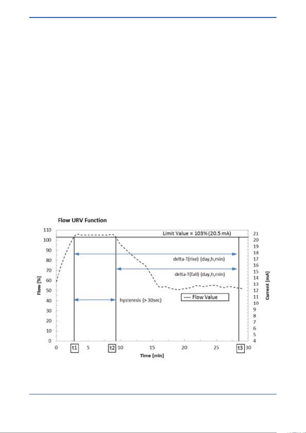
<7. HART-COMMUNICATION>
7-35
Device Setup
Diag/Service
Diagnostics
Flow URV log
Flow URV log ON/OFF Activate or deactivate Flow URV
Logging function
URV overrun time Days/Hours Time since…
Minutes … exceeding URV
URV underrun time Days/Hours Time since…
Minutes … fall below URV
Min overrun time Selection of hysteresis time
Clear values Clears the values in URV overrun time and URV
underrun time
Description of Flow URV logging function
The ow value is supervised constantly. As soon as the value reaches the upper limit value (103 %; 20.5 mA) event
1 is recognized. If this error condition remains actively longer than the hysteresis value, the limiting value recognition is activated, the overrun condition and the time stamp is stored.
As soon as the ow value falls below the limit value, the supervision ends, the underrun condition and the event 2
time stamp is stored. For a new cycle the hysteresis time must pass.
After the recognition you can request the passed time:
Time stamp from event1 till time stamp from event2: delta-Time
The time difference is the time the upper limit was exceeded: hysteresis <= t <= delta-time
The actual cycle is overwritten automatically by a new one. The stored values will be cleared after power off. The
default value for hysteresis is 30 seconds.
All Rights Reserved. Copyright © 2003, Rota Yokogawa
IM 01R01B02-00E-E 14th edition January 20, 2017 -00
Page 84

7-36
<7. HART-COMMUNICATION>
Device Setup
Diag/Service
Diagnostics
Float blocking
Float blocking ON/OFF Activate or deactivate oat blocking
Set lower limit 5 %/ 15 %/ 30 % Set lower limit of supervision range
Set supervise time Turbulent ow
Smooth ow
Start autozero Start
Autozero value Shows autozero value
See description of oat blocking function in chapter 6.2.14
Device Setup
Diag/Service
Power monitoring
Operation time Days Count of days since operation starts.
Hours Count of hours since operation starts.
Minutes Count of minutes since operation starts.
Oper time shadow Days Counts of days until last reset.
Hours Counts of hours until last reset.
Minutes Counts of minutes until last reset.
Reset power fail Power fail warning is cleared.
Description of power monitoring function:
This function counts up the operation minutes and stores the time in the parameter “Operation time”.
After “Power on”, “Master Reset” or “Device Reset” the actual time stamp is stored in parameter
“Oper time shadow”. The time difference to “Operation Time” gives the last point in time of reset.
After power off/on the power fail warning is set. It can be cleared by “Reset power fail” or “Reset all errors”.
The “Operation time” is the base for the time stamps of “Temp max log” and “Flow URV log”.
Device Setup
Diag/Service
Real-Time Clock
Current Date Current calendar date
Current Time Current day time
Set Clock Date Last entered current calendar date
Set Clock Time Last entered current day time
Real Time Clock ags Counts changes on Real-time Clock.
Set Real-time Clock Enter current calendar date and day time.
Description of real time clock function:
The real-time clock has to be set by the parameter “Set Real-time Clock”
This function counts up the operating time and stores the values in the parameter “Current Date” and “Current
Time”. “Set Clock Date” and “Set Clock Time” stores the last entered date/time.
The time value is reset to “00:00:00” after 24 hours (23:59:59).
After “Power on”, “Master Reset” or “Device Reset” the Real-time Clock is set to its initial value:
01/01/1900 00:00:00
IM 01R01B02-00E-E 1414th edition January 20, 2017 -00
All Rights Reserved. Copyright © 2003, Rota Yokogawa
Page 85

<7. HART-COMMUNICATION>
7.6.3 Basic- Setup Menu
Device Setup
Basic setup
Tag Tag Number (8 characters)
Long tag Long Tag Number (32 characters)
Flow unit select Flow measurement unit
Temperature unit Temperature measurement unit
Flow damp Damping time for ow value
7.6.4 Detailed- Setup Menu
Device Setup
Detailed setup
Characterize meter
Operating Conditions
Density User’s density on scale
Viscosity User’s viscosity on scale
Temperature User’s temperature on scale
Pressure User’s pressure on scale
Reference Pressure User’s pressure reference
Pressure conditions User’s pressure conditions
Medium data
Fluid name User’s uid name
Fluid phase User’s uid phase
Flow Reference User’s ow reference
Flow scale unit Flow measurement unit in accordance with scale
Scale USL Upper sensor limit related to scale unit
MS Code Ordering code of the device
RAMC s/n Serial number of the measuring tube
RAMC rmware rev Firmware revision of the device
7-37
Device Setup
Detailed setup
Congure signal
Flow damp Set damping time for ow value
Flow unit select Select ow measurement unit
Total reset Set totalized value to zero
Temperature unit Select temperature unit degC / degF
All Rights Reserved. Copyright © 2003, Rota Yokogawa
IM 01R01B02-00E-E 14th edition January 20, 2017 -00
Page 86

7-38
<7. HART-COMMUNICATION>
Device Setup
Detailed setup
Congure signal
Flow unit select
L/s L/min L/h
Cum/s Cum/min Cum/h Cum/d
gal/s gal/min gal/h gal/d
Impgal/s Impgal/min Impgal/h Impgal/d
Cuft/s Cuft/min Cuft/h Cuft/d
bbl/s bbl/min bbl/h bbl/d
NL/min NL/h
NCum/min NCum/h
StdL/min StdL/h
StdCum/min StdCum/h
StdCuft/min StdCuft/h
g/s g/min g/h
kg/s kg/min kg/h kg/d
t/min t/h t/d
lb/s lb/min lb/h lb/d
LTon/min LTon/h LTon/d
Device Setup
Detailed setup
Congure output
Analog output
PV Loop current Current output in mA
PV LRV Lower range value related to the current output
PV URV Upper range value related to the current output
PV Alrm typ Current level at error
Loop Current mode Enable mode of variable output current
Loop Test Set the analogue output x to 4 mA, 20 mA or arbitrary
current.
D/A Trim Adjustment of current output to 4 mA and 20 mA.
Device Setup
Detailed setup
Congure output
HART output
Poll addr Poll Address (Function see above) (Def.: 0)
Num req preams Number of leading FF to HART unit (Def.: 5)
Num resp pream Number of leading FF from HART unit (Def.:5)
Burst conguration See chapter 7.6.7
Trend conguration See chapter 7.6.9
PV is Assignment of primary variable
SV is Assignment of secondary variable
TV is Assignment of tertiary variable
QV is Assignment of quaternary variable
IM 01R01B02-00E-E 1414th edition January 20, 2017 -00
All Rights Reserved. Copyright © 2003, Rota Yokogawa
Page 87

<7. HART-COMMUNICATION>
Device Setup
Detailed setup
Congure output
HART output
Burst conguration See chapter 7.6.7
Burst Message 1
Burst Message 2
Burst Message 3
Event Notication See chapter 7.6.8
Flow Update Time Period Time between 2 measurements
Total Update Time Period Time between 2 measurements
Percent Update Time Period Time between 2 measurements
Temp Update Time Period Time between 2 measurements
Device Setup
Detailed setup
Congure output
HART output
Trend conguration See chapter 7.6.9
Number of trends supported
Trend Control
Trend Device Variable
Trend Sample Interval
Trend Data
7-39
Device Setup
Detailed setup
Display selection
Selection of measuring value on display:
For standard calibration table: Flow - Totalizer - Percent - Temperature
For manual calibration table: Percent - Temperature
Device Setup
Detailed setup
Device Information
Model Model name
Dev ID Device ID
Manufacturer Manufacturer
Distributor Distributor
Final asmbly no Number of nal assembly
Write protect Write protection
Cfg chng count Number of conguration changes
Tag Type in Tag-Number
Long tag Type in Long Tag-Number
Descriptor Type in description
Message Type in message
Date Type in Date
Poll addr Type Poll Address
Loop Current mode Enable mode of variable output current
Num req pream Number of leading FF to HART unit
Num rsp pream Number of leading FF from HART unit
MS Code Ordering code of the device
RAMC s/n Serial number of the measuring tube
RAMC rmware rev Firmware Version of the Device
Device Prole Process automation device
Revision #’s Revision numbers
Universal rev HART Universal Revision (7)
Fld. dev. rev Field device Revision
Hardware rev Hardware Revision
Software rev Software Revision
ADJ-EE rev Adjustment-EEPROM Revision
CAL-EE rev Calibration-EEPROM Revision
All Rights Reserved. Copyright © 2003, Rota Yokogawa
IM 01R01B02-00E-E 14th edition January 20, 2017 -00
Page 88

7-40
<7. HART-COMMUNICATION>
7.6.5 Write protect menu
Write protect menu
Write protect Read Status of write protection
Enable wrt 10min Enable writing for 10 minutes by entering password.
After writing a parameter the time of 10 minutes starts again.
New password Selection of a new password by entering up to 8 character
If 8 blanks are entered as new password, write protection is disabled. If the user
password is lost, a joker password is available from the YOKOGAWA service
department.
7.6.6 Review Menu
Review
Model Model name (RAMC)
Dev id Device ID
Manufacturer Manufacturer (Yokogawa)
Distributor Distributor (Yokogawa)
Final asmbly num Number of nal assembly
Write Protect Write protection
Cfg chng count Number of conguration changes
Max dev vars Max number of device variables
Tag Tag Number
Long tag Long Tag Number
Descriptor Description
Message Message
Date Date
Poll address Poll address
AO Alrm typ Current level at error (PV Alrm typ)
Loop Current mode Enable mode of variable output current
Num req pream Number of leading FF to HART - unit
Num rsp pream Number of leading FF from HART - unit
MS Code Ordering code of the device
RAMC s/n Serial number of the measuring tube
RAMC rmware rev Firmware Version of the Device
Universal rev HART Universal Revision (7)
Fld. dev. rev Field device Revision
Hardware rev Hardware Revision
Software rev Software Revision
ADJ-EE rev Adjustment-EEPROM Revision
CAL-EE rev Calibration-EEPROM Revision
7.6.7 Burst Mode (Only available in HART 7)
When the Burst mode is set to “Wired HART Enabled”, the transmitter continuously sends up to three data listed in
table on page 7-42 Refer to the chapter 7.6.7.1 Burst Message for details.
When the Burst mode is set to “Wired HART Enabled”, the transmitter can continuously sends alarm signal also.
Refer to chapter 7.6.8 Event Notication for activating this function.
When changing the setting of Burst mode, set “Off” to the Burst mode. Default setting is “Off”.
IM 01R01B02-00E-E 1414th edition January 20, 2017 -00
All Rights Reserved. Copyright © 2003, Rota Yokogawa
Page 89

<7. HART-COMMUNICATION>
Burst
Command?
Burst Msg
Trigger Mode?
Update Period
Max Update Period
Burst Command
Burst mode
Burst Msg Trigger Mode
Continuous
Window
Rising
Falling
On-change
Send to RAMC
Send to RAMC
Send to RAMC
Send to RAMC
Cmd9, Cmd33
a. Burst Command
b.
Burst Variable Code
c.
Update period and
Max Update Period
by “Set Burst Period”
d. Burst Msg Trigger Mode
by “Set Burst Trigger”
e. Burst Mode
Cmd1, Cmd2,
Cmd3, Cmd48
Burst Variable Code
Burst Trigger Level
Send to RAMC
F77.EPS
7-41
(1) Burst message
RAMC transmitter can transmit three burst messages at the maximum. The parameters for Burst Message
are as follows.
• Burst Command
• Update Period and Max Update Period
• Burst Msg Trigger Mode
(2) Burst mode setting procedure
DD (HART 7) [Root Menu] → Device setup → Detailed setup →
Congure output → HART output → Burst conguration
→ Burst Message 1,2 or 3 → Burst Command
All Rights Reserved. Copyright © 2003, Rota Yokogawa
IM 01R01B02-00E-E 14th edition January 20, 2017 -00
Page 90

7-42
<7. HART-COMMUNICATION>
a) Burst Command
Select the transmission data at Burst Command parameter.
Burst Command Command Parameter
Cmd1: PV Variable assigned to PV
Cmd2: % range/current % range/current (Percent range, Loop current)
Cmd3: Dyn vars/current Process vars/current (Loop current, PV, SV, TV,QV)
Cmd9: Device vars w/ Status Process vars/% range/ current with status Mapping by user
Cmd33: Device variables Process vars (PV, SV, TV,QV)
Cmd48: Read Additional Device Status Self-diagnosis information
Burst parameters
Command parameter
PV (Either of from
ow, total, percent,
temp)
Burst Command Burst Msg Trigger
Mode
Burst Trigger
Source
Burst Trigger Units
Cmd1: PV Continuous --- ---
Window PV Depend on the assiRising
gned variable to PV
Falling
On-change
% range/current
(Percent range, Loop
current)
Cmd2: % range/
current
Continuous --- --Window % range %
Rising
Falling
On-change
Process vars/current
(Loop current, PV,
SV, TV,QV)
Cmd3:Dyn vars/
current
Continuous --- --Window PV Depend on the assi-
Rising
gned variable to PV
Falling
Process vars/% range/ current with sta-
Cmd9: Device vars
w/ Status
tus *1 (Select up to
eight variables from
ow, total, percent,
temp, percent range,
loop current)
Process vars (Select
up to four variables
Cmd33: Device
variables
from ow, total, percent, temp)
Self-diagnosis information
Cmd48: Read Additi-
onal Device Status
*1: Output the data with time and status.
On-change
Continuous --- ---
Window Top of Burst Device
Depends on mapping
Variables
Rising
Falling
On-change
Continuous --- --Window Top of Burst Device
Rising
Variables
Depends on mapping
Falling
On-change
Continuous --- ---
IM 01R01B02-00E-E 1414th edition January 20, 2017 -00
All Rights Reserved. Copyright © 2003, Rota Yokogawa
Page 91

<7. HART-COMMUNICATION>
7-43
b) Burst Variable Code
This parameter need to be set when Burst Command is Cmd9:
Device variables with status (up to eight items).
DD (HART 7) [Root Menu] → Device setup → Detailed setup → Congure output → HART output → Burst
conguration → Burst Message 1,2 or 3 → Burst device variables → Burst variables
Display item Contents
Flow Select the ow rate
Total Select the totalized ow
Percent Select the ow % rate
Temp Select the onboard temperature
Percent range Select the current % rate
Loop current Select the output current value
Not used All items up to this selection are transmitted
c) Burst Update Period and Max Update Period
Set the Update Period and the Max Update Period.
The Update Period species the rate at which data is transmitted as long as the trigger conditions of the Burst
Msg Trigger Mode are met. The Max Update Period species the rate at which data is transmitted as long as the
trigger conditions of the Burst Msg Trigger Mode are not met.
DD (HART 7) [Root Menu] → Device setup → Detailed setup → Congure output → HART output → Burst
conguration → Burst Message 1,2 or 3 → (Max) Update Period
Update Period
/ Max Update
Period
0.5 s
1 s
2 s
4 s
8 s
16 s
32 s
60 s – 3600 s any value
d) Burst Msg Trigger Mode
Set the Burst Msg Trigger Mode from the parameters shown below. When Burst Msg Trigger Mode is Window,
Rising or Falling, set the Burst Trigger Level.
DD (HART 7) [Root Menu]→ Device setup → Detailed setup → Congure output → HART output → Burst
conguration → Burst Message 1,2 or 3 → Burst Msg Trigger Mode
Display item Contents
Continuous Burst message is transmitted continuously
Window In “Window” mode, the Trigger Value must be a positive number and is the symmetric window
around the last communicated value
Rising In “Rising” mode, the Burst Message must be published when the source value exceeds the
threshold established by the trigger value.
Falling In “Falling” mode, the Burst Message must be published when the source value fall below the
threshold established by the trigger value.
On-change In “On-change” mode, the Burst Message must be published when the source value on change
established by the trigger value.
All Rights Reserved. Copyright © 2003, Rota Yokogawa
IM 01R01B02-00E-E 14th edition January 20, 2017 -00
Page 92

7-44
<7. HART-COMMUNICATION>
e) Burst Mode
DD (HART 7) [Root Menu] → Device setup → Detailed setup →
Congure output → HART output → Burst conguration → Burst Message 1,2 or 3 → Burst mode → Wired
HART Enabled
When the Burst mode is set to “Wired HART Enabled”, the transmitter starts to send the data.
Detailed Burst Menu Structure
Device Setup
Detailed setup
Congure output
HART output
Burst conguration
Burst Message 1
Burst 1 Mode R/S
Burst 1 Command R/S
Update Period R
Max Update Period R
Classication R
Trigger Mode R
Trigger Units R
Trigger Level R
Set Burst 1 Period Perform
Method to select update/max update period
Set Burst 1 Trigger Perform
Method to select trigger conditions
Burst 1 variables R/S
Burst Message 2
Burst 2 Mode R/S
Burst 2 Command R/S
Update Period R
Max Update Period R
Classication R
Trigger Mode R
Trigger Units R
Trigger Level R
Set Burst 2 Period Perform
Method to select update/max update period
Set Burst 2 Trigger Perform
Method to select trigger conditions
Burst 2 variables R/S
Burst Message 3
Burst 3 Mode R/S
Burst 3 Command R/S
Update Period R
Max Update Period R
Classication R
Trigger Mode R
Trigger Units R
Trigger Level R
Set Burst 3 Period Perform
Method to select update/max update period
Set Burst 3 Trigger Perform
Method to select trigger conditions
Burst 3 variables R/S
IM 01R01B02-00E-E 1414th edition January 20, 2017 -00
All Rights Reserved. Copyright © 2003, Rota Yokogawa
Page 93

<7. HART-COMMUNICATION>
7-45
7.6.8 Event Notication (Only available in HART 7)
When a setting change and a change of the Self- diagnostics occur, the device detects it as an event and can
transmit an alarm signal continuously. Up to three events that occurred can be stored. When using this function, set
to Burst mode as “Wired HART Enabled”.
(1) Set Event Notication
• Procedure to call up the display
DD (HART 7) [Root Menu] → Device setup → Detailed setup → Congure output → HART
output → Burst conguration → Event Notication →
→ Event Notication Control Stop the event monitor: Off Shift to the monitor state: Enable event notication
on token- passing data link layer
→ Event Notication Retry Time Set the retry time when the event occurs.
→ Max Update Time Set the retry time when the event does not occur.
→ Event Debounce Interval The setting of the minimum event duration
→ Event Mask Set the status to detect
a) Event Notication Control
Select “Enable event notication on token-passing data link layer” in the Event Notication Control parameter to
shift to the monitor state.
b) Event Notication Retry Time/ Max Update Time/ Event Debounce Interval
Set to Event Notication Retry Time, Max Update Time and Event Debounce Interval. For Event Notication Retry Time, set the value that is smaller than Max Update Time.
Event Notication Retry Time / Max Update Time Event Debounce Interval
0.5 s 0.5 s
1 s 1 s
2 s 2 s
4 s 4 s
8 s 8 s
16 s 16 s
32 s 32 s
>60 s – 3600 s any value >60 s – 3600 s any value
c) Event Status
Indicates the type of the pending events. The bits will be cleared after the appropriate latched value and the
trigger time is acknowledged by Clear Event Data.
Event Status Code Description
Conguration changed event pending 0x01 The pending event is caused by a conguration change
Device status event pending 0x02 The pending event is caused by a device status change
More status available event pending 0x04 The pending event is caused by a more status available change
d) Event Mask
Set the status to be detected in the Event Mask parameter.
Device Status Mask
Ext Dev Status Mask
Device Diagnostic Status 0 Mask
Bit mask assignment (see table on page 7-47)
Device Specic Status 0 Mask
Device Specic Status 1 Mask
All Rights Reserved. Copyright © 2003, Rota Yokogawa
IM 01R01B02-00E-E 14th edition January 20, 2017 -00
Page 94

7-46
<7. HART-COMMUNICATION>
e) Event Report
Read the detected status in the appropriate Event Report parameter.
Device Status Latched Value
Ext dev status Latched Value
Device Diagnostic Latched Value
Latched value assignment (see table on page 7-47)
Device Specic Status 0 Latched Value
Device Specic Status 1 Latched Value
Time First Unack Event Triggered Time of event trigger (Default when cleared: 13:16:57)
Cong Change Counter Latched Value Latched conguration changed counter value
Event Status Status of pending events
Read Event Data Perform reading of the oldest pending event data
Clear Event Data Acknowledge of the oldest pending event data
Detailed Event Notication Menu Structure
Device Setup
Detailed setup
Congure output
HART output
Burst conguration
Event Notication
Event Notication Control R/S
Event Notication Retry Time R/S
Max Update Time R/S
Event Debounce Interval R/S
Event Mask
Device Status Mask S
Ext Dev Status Mask S
Device Diagnostic Status 0 Mask S
Device Specic Status 0 Mask S
Device Specic Status 1 Mask S
Event Report
Device Status Latched Value R
Ext Dev Status Latched Value R
Device Diag. Status 0 Latched Value R
Device Spec. Status 0 Latched Value R
Device Spec. Status 1 Latched Value R
Time First Unack Event Triggered R
Cfg Change Counter Latched Val R
Event Status R
Read Event Data Perform
Clear Event Data Perform
IM 01R01B02-00E-E 1414th edition January 20, 2017 -00
All Rights Reserved. Copyright © 2003, Rota Yokogawa
Page 95

<7. HART-COMMUNICATION>
Table: Status bit (code) assignment
Device status Code Mask Latched Value
Process applied to primary variable is out of range 0x01 OFF/ON OFF/ON
Process applied to non-primary variable is out of range 0x02 OFF/ON OFF/ON
PV Analog Channel Saturated 0x04 OFF/ON OFF/ON
PV Analog Channel Fixed 0x08 OFF/ON OFF/ON
Field Device has more status available 0x10 OFF/ON OFF/ON
A reset or self test of the eld device has occurred 0x20 OFF/ON OFF/ON
A modication has been made to the conguration 0x40 OFF/ON OFF/ON
Field device has malfunction due to a hardware problem 0x80 OFF/ON OFF/ON
Ext dev status Code Mask Latched Value
Maintenance required 0x01 OFF/ON OFF/ON
Device variable alert 0x02 OFF/ON OFF/ON
Critical Power failure 0x04 OFF/ON OFF/ON
PV Analog Channel Fixed 0x08 OFF/ON OFF/ON
7-47
Device Diagnostic Status 0 Code Mask Latched Value
Simulation active 0x01 OFF/ON OFF/ON
Non-Volatile memory failure 0x02 OFF/ON OFF/ON
Volatile memory error 0x04 OFF/ON OFF/ON
Watchdog Reset executed 0x08 OFF/ON OFF/ON
Voltage condition out of range 0x10 OFF/ON OFF/ON
Environmental condition out of range 0x20 OFF/ON OFF/ON
Electronic failure 0x40 OFF/ON OFF/ON
Device conguration locked 0x80 OFF/ON OFF/ON
Status group 0 Code Mask Latched Value
RAM Error Memory error 0x01 OFF/ON OFF/ON
ADC Error Error at A/D converter 0x02 OFF/ON OFF/ON
ADJ-EE-Error Error in adjustment-EEPROM 0x04 OFF/ON OFF/ON
CAL-EE Error Error in calibration-EEPROM 0x08 OFF/ON OFF/ON
Totalizer false Totalizer value fault 0x10 OFF/ON OFF/ON
Flow Overrun Flow too high 0x20 OFF/ON OFF/ON
ADJ-EE Error 2 Adjustment-EEPROM fault 0x40 OFF/ON OFF/ON
Float blocked Float-Move-Detection recognized 0x80 OFF/ON OFF/ON
Status group 1 Code Mask Latched Value
Temp over limit Temperature exceeds 70°C 0x01 OFF/ON OFF/ON
Max ow1 active URV overrun 0x02 OFF/ON OFF/ON
Max ow2 active URV underrun 0x04 OFF/ON OFF/ON
FB autoz active Float blocking autozero on 0x08 OFF/ON OFF/ON
Power fail warn Power off has happened 0x10 OFF/ON OFF/ON
Oper timer error Operation timer fault 0x20 OFF/ON OFF/ON
Man adjust act. Manual adjustment activated 0x40 OFF/ON OFF/ON
FB indicat. act. Float-Move-Detection activated 0x80 OFF/ON OFF/ON
All Rights Reserved. Copyright © 2003, Rota Yokogawa
IM 01R01B02-00E-E 14th edition January 20, 2017 -00
Page 96

7-48
<7. HART-COMMUNICATION>
7.6.9 Trend conguration (Only available in HART 7)
Data Trending is intended to reduce the number of transmissions to get data from a device. This can be useful for
monitoring applications that do not need to get all data with low latency.
The RAMC supports the transmission of 1 trend information of a desired device variable.
When the Trend control is set from “Disabled”, to one of the following three settings the transmitter continuously
calculates the trend data to be transmitted to the host.
Trend Control Function
Disabled No trend information will be calculated
Enable single data point trending Only the value that was read during the occurrence of
the sampling will be kept in the ring buffer.
Enable ltered trending A ltered trend uses a time constant equal to one-third
of the trend sample period to smooth the data.
Consider a step change in the device variable value,
this averaging time constant allows the returned trend
value to reach 95 % of the step change in one trend
sample period.
Enable average trending The device averages the values that were taken during
the trend sample period.
The values to be transmitted are the following:
Trend Device Variable Parameter
Flow Flow in measurement unit
Percent Percent value of ow
Temperature Temperature in transmitter
The sampling interval is selectable in the range of 1 s up to 2 h. The internal measurement cycle is 250 ms.
The RAMC supports one ring buffer with 12 samples in length. The ring buffer is updated with samples of the
desired device variable value at the rate indicate by the sample period.
The trend data can be displayed in the following menu by applying the parameter “Refresh Trend Data” to the device.
All 12 trend data values will be displayed.
When a Trend is not used it transmits NAN for the values and as status “bad / constant”.
Device Setup
Detailed setup
Congure output
HART output
Trend conguration
Trend Data
Refresh Trend Data Perform
Trend Device Variable R/S
Trend Classication R
Trend Units R
Trend 0 Date Stamp R
Trend 0 Time Stamp R
Trend Value (x) R
Trend Value (x) Data Quality R
Trend Value (x) Limit Status R
(x) = 12 values
IM 01R01B02-00E-E 1414th edition January 20, 2017 -00
All Rights Reserved. Copyright © 2003, Rota Yokogawa
Page 97

<7. HART-COMMUNICATION>
Wire the unit according
the connection diagram
Select correct load
Select correct voltage
Load HART- DD for
RAMC in communicator
(Yokogawa Service)
Change communicator
RAMC to Yokogawa Service
Is the unit wired correctly?
Is load resistance in the correct
range?
Is supply voltage in the correct
range?
Does HART -communicator
contain DD for RAMC?
Communicator OK ?
T76.EPS
HART- Test
7.7 Maintenance
7.7.1 Function test
· Wire the unit according to the connection diagram.
· Check HART- communication with HART- communicator or with PC with HART- ability
communication program.
· Setting: Device setup / Process variables.
· PV AO shows the current value; compare this value with the measured current.
7.7.2 Troubleshooting
Do the following test if problems with HART units appear:
7-49
All Rights Reserved. Copyright © 2003, Rota Yokogawa
IM 01R01B02-00E-E 14th edition January 20, 2017 -00
Page 98

7-50
<7. HART-COMMUNICATION>
Blank Page
IM 01R01B02-00E-E 1414th edition January 20, 2017 -00
All Rights Reserved. Copyright © 2003, Rota Yokogawa
Page 99

<8. SERVICE>
8-1
8.
Service
8.1 Maintenance
8.1.1 Function test
Checking free movement of pointer:
- Remove housing cover.
- After deecting the pointer by hand, it must return to measurement value. If the pointer pivots to different
values upon repeated deections, there is too much friction in the bearings. In this case, send indication unit
to service.
Checking free movement of oat:
- First, free movement of pointer has to be ascertained.
- Check visually if pointer follows each ow rate change. If not, clean oat and measuring tube.
Unit with electronic transmitter:
- The display must show values corresponding to indication function and measuring unit settings.
- The bars under the 8 digits must not ash. If an error occurs, the corresponding countermeasure (refer to
chapter 6.2.8 error messages) has to be taken or the unit has to be sent to service.
- Without ow, the output current must be 0 or 4 mA. At a ow rate of 100 % the current must be 20 mA.
Additional function test for HART units (-H, -J)
- check HART communication using a HART Handheld terminal or a PC with HART communication
software.
- Setting: Device setup / Process variables
- PV AO shows the current value that should be delivered at output – Check this value using a multimeter.
8.1.2 Measuring tube, oat
The RAMC is maintenance-free. If contamination of the measuring tube impairs the mobility of the oat, the tube
and the oat have to be cleaned. To do this, the RAMC has to be removed from the pipe.
Replacement or cleaning of the oat:
- Remove RAMC from the pipe.
- Remove upper retainer from metering tube.
- Take oat stopper and oat out through the top of metering tube.
- Clean oat and metering cone.
- Insert oat and oat stopper into the metering tube.
- Set retainer into tube.
- Check oat for free movement.
- Install RAMC to the pipe.
Attention: Do not expose oat to strong alternating magnetic elds. The oat and especially its measuring
edge must not be damaged.
All Rights Reserved. Copyright © 2003, Rota Yokogawa
IM 01R01B02-00E-E 14th edition January 20, 2017 -00
Page 100

8-2
1
2
3
4
6
5
<8. SERVICE>
8.1.3 Explosion drawing
Number Part
1 Circlip
2 Float stop
3 Float
4 Float stop welded in
5 Cone
6 Indicator
IM 01R01B02-00E-E 14th edition January 20, 2017 -00
All Rights Reserved. Copyright © 2003, Rota Yokogawa
 Loading...