

Page 1

User´s
Model RAMC
Manual
IM 01R01B02-00E-E
Metal Short Stroke ROTAMETER
Rota Yokogawa GmbH & Co. KG
Rheinstr. 8
D-79664 Wehr
Germany
IM 01R01B02-00E-E
©Copyright 2003 (Rü)
10th edition, January 2013 (Rü)
Page 2

Blank Page
Page 3

<CONTENTS>
i
Contents
1. Introduction ......................................................................................... 1-1
1.1 ATEX Documentation ......................................................................................1-3
1.2 General description .........................................................................................1-4
1.3 Principle of measurement .............................................................................. 1-4
1.4 Overview ........................................................................................................... 1-5
2. Precautions .........................................................................................2-1
2.1 Transportation and storage ............................................................................2-1
2.2 Installation .......................................................................................................2-1
2.3 Pipe connections ............................................................................................2-1
3. Installation ..........................................................................................3-1
3.1 Installation in the pipeline .............................................................................3-1
3.2 Wiring of electronic transmitter (-E, -H) and limit switches (/K_) ..............3-2
4. Start of operation ...............................................................................4-1
4.1 Hints on ow rate measurement ...................................................................4-1
4.2 Pulsation and pressure shock .......................................................................4-1
4.3 Start of operation of electronic transmitter .................................................4-1
5.
Limit switches (Option /K[]) ...........................................................................................5-1
All Rights Reserved. Copyright © 2003, Rota Yokogawa
IM 01R01B02-00E-E 10th edition January 01, 2013 -00
Page 4

<CONTENTS>ii
6. Electronic Transmitter (-E) .................................................................6-1
6.1 Operation principle .........................................................................................6-1
6.2 Parameter setting ............................................................................................6-1
6.2.1 Selection of indication function (F11) ............................................................... 6-4
6.2.2 Setting the unit (F12 / F13) ................................................................................. 6-5
6.2.3 Totalizer reset (F14) ............................................................................................. 6-7
6.2.4 Selection of temperature unit (F15) ................................................................... 6-7
6.2.5 Setting of damping (F2-) ..................................................................................... 6-8
6.2.6 Selection / Adjustment 4-20 mA / 0-20 mA (F3-) .............................................. 6-8
6.2.7 Pulse output (F34) (Option /CP) ......................................................................... 6-9
6.2.8 Error messages (F4-) ......................................................................................... 6-12
6.2.9 Manual adjustment (F5-) ................................................................................... 6-13
6.2.10 Revision indication (F61/F62) ......................................................................... 6-16
6.2.11 Current output test (F63) ................................................................................. 6-16
6.2.12 Switching between standard / Indicator on extension (F64) ...................... 6-17
6.2.13 Master Reset (F65) ........................................................................................... 6-17
6.2.14 Float blocking indication (F7-) ........................................................................ 6-18
7.
HART® - Communication ..................................................................................... 7-1
7.1 General .............................................................................................................7-1
7.2 Connection ....................................................................................................... 7-2
7.3 HART Menu (Rev 01 DD rev 02) ..................................................................7- 3
7.4. Description of the HART®- Parameter........................................................... 7- 6
7.4.1 Process variables ..................................................................................................7-7
7.4.2 Diagnostic- and Service-Menu .............................................................................7- 7
7.4.3 Basic-Setup Menu ...............................................................................................7- 13
7.4.4 Detailed-Setup Menu ...........................................................................................7- 13
7.4.5 Review ..................................................................................................................7- 15
7.5 Maintenance ................................................................................................... 7-16
7.5.1 Function test ........................................................................................................7-16
7.5.2 Troubleshooting ................................................................................................... 7-16
IM 01R01B02-00E-E 10th edition January 01, 2013 -00
All Rights Reserved. Copyright © 2003, Rota Yokogawa
Page 5

<CONTENTS>
8.
Service .......................................................................................................... 8-1
iii
8.1 Maintenance ....................................................................................................8-1
8.1.1 Function test ......................................................................................................... 8-1
8.1.2 Measuring tube, oat ........................................................................................... 8-1
8.1.3 Explosion drawing ............................................................................................................... 8-2
8.1.4 Electronic transmitter .......................................................................................... 8-3
8.1.5 Exchange of EEPROM and scale ....................................................................... 8-3
8.1.6 Exchange of indicator .......................................................................................... 8-4
8.1.7 Troubleshooting .................................................................................................... 8-4
8.2 Template for sending back to service ..........................................................8-6
9. Technical Data ....................................................................................9-1
9.1 Model- and suffix-codes .................................................................................9-1
9.2 Options ............................................................................................................9-2
9.3 Standard Specications .................................................................................9-4
9.4 Dimensions and weights..............................................................................9-15
9.5 Temperature graphs for RAMC metal design, standard and intrinsic safe .....
...............................................................................................................................9-18
10.
Explosion-protected Type Instruments .......................................... 10-1
10.1 General ......................................................................................................... 10-1
10.1.1 Intrinsic safety ................................................................................................. 10-1
10.1.2 Flame proof ...................................................................................................... 10-1
10.2
Intrinsically safe ATEX certied components (/KS1) .................................10-2
10.2.1 Technical data .................................................................................................. 10-2
10.2.2 Installation ........................................................................................................ 10-3
10.2.3 Marking ............................................................................................................. 10-3
10.3
All Rights Reserved. Copyright © 2003, Rota Yokogawa
Nonincendive components for Category 3 (ATEX) (/KN1) ...................... 10-4
10.3.1 Technical data .................................................................................................... 10-4
10.3.2 Installation ........................................................................................................ 10-5
IM 01R01B02-00E-E 10th edition January 01, 2013 -00
Page 6

<CONTENTS>iv
10.4 Intrinsically safe SAA (Australia) certied RAMC (/SS1) ........................10-5
10.4
10.5
10.6
Intrinsically safe ATEX certied components for category 3G (/KS3) .....10-6
10.4.1 Technical data .................................................................................................. 10-6
10.4.2 Marking ............................................................................................................. 10-7
Intrinsically safe IECEx- certied components (/ES1) ..................................10-8
10.5.1 Technical data .................................................................................................. 10-8
10.5.2 Installation ........................................................................................................ 10-9
10.5.3 Marking ............................................................................................................. 10-9
Intrinsically safe IECEx- components for category 3G (/ES3) .................10-10
10.6.1 Technical data .................................................................................................10-10
10.6.2 Marking ............................................................................................................ 10-11
10.7 Intrinsically safe FM / CSA (USA + Canada) components (/FS1, /CS1) ......... 10-12
10.7.1 Electronic transmitter (/FS1 for USA, /CS1 for Canada) ..............................10-12
10.7.2 Limit switches option /K1 ... /K10 (/FS1 for USA)..........................................10-15
10.6.3 Limit switches option /K1 ... /K3 (/CS1 for Canada) .....................................10-15
10.8 Intrinsically safe NEPSI (China) certied RAMC (/NS1) ................................. 10-21
10.9 Flame proof and dust proof ATEX certied RAMC (/KF1) ....................10-22
10.9.1 Technical data ................................................................................................ 10-22
10.9.2 Installation ...................................................................................................... 10-23
10.9.3 Operation ........................................................................................................ 10-23
10.10 Flame proof and dust proof IECEx certied RAMC (/EF1) .................10-24
10.10.1 Technical data ............................................................................................... 10-24
10.10.2 Installation .................................................................................................... 10-25
10.10.3 Operation ...................................................................................................... 10-25
10.11 Intrinsically safe ATEX certied components in dust proof RAMC-housing
(/KS2) ...................................................................................................................10-26
10.12 Intrinsically safe IECEx certied components in dust proof RAMC- hou-
sing (/ES2) ........................................................................................................... 10-26
IM 01R01B02-00E-E 10th edition January 01, 2013 -00
All Rights Reserved. Copyright © 2003, Rota Yokogawa
Page 7

<CONTENTS>
v
10.13 Flame proof and dust proof NEPSI (China) certied RAMC (/NF1) ....10-27
10.13.1 Technical data ............................................................................................... 10-27
10.13.2 Installation .................................................................................................... 10-27
10.13.3 Operation ...................................................................................................... 10-28
11. Instructions for PED ....................................................................... 11-1
APPENDIX 1. SOFTWARE CHANGE HISTORY ................................. A1-1
APPENDIX 2. Safety Instrumented Systems Installation .................A2-1
A2.1 Scope and Purpose .................................................................................... A2-1
A2.2 Using RAMC for a SIS Application ........................................................... A2-1
A2.2.1 Safety Function.................................................................................................A2-1
A2.2.2 Diagnostic Response Time ..............................................................................A2-2
A2.2.3 Setup ..................................................................................................................A2-2
A2.2.4 Proof Testing ..................................................................................................... A2-2
A2.2.5 Repair and replacement ..................................................................................A2-3
A2.2.6 Startup Time ......................................................................................................A2-3
A2.2.7 Firmware update ............................................................................................... A2-3
A2.2.8 Reliability data ..................................................................................................A2-3
A2.2.9 Lifetime limits ...................................................................................................A2-3
A2.2.10 Required parameter settings .........................................................................A2-3
A2.2.11 Environmental limits ......................................................................................A2-4
A2.2.12 Application limits ............................................................................................A2-4
A2.3 Denitions and Abbreviations ................................................................... A2-4
A2.3.1 Denitions .........................................................................................................A2-4
A2.3.2 Abbreviations ....................................................................................................A2-4
A2.4 Assessment results .................................................................................... A2-5
A2.4.1 Safety related parameters ...............................................................................A2-5
All Rights Reserved. Copyright © 2003, Rota Yokogawa
IM 01R01B02-00E-E 10th edition January 01, 2013 -00
Page 8

<CONTENTS>vi
Blank Page
IM 01R01B02-00E-E 10th edition January 01, 2013 -00
All Rights Reserved. Copyright © 2003, Rota Yokogawa
Page 9
1. Introduction
WARNING
CAUTION
IMPORTANT
NOTE
WARNING
<1. INTRODUCTION>
1-1
Before use, read this manual thoroughly and
familiarize yourself fully with the features,
operations and handling of Rotameter RAMC to have
the instrument deliver its full capabilities and
to ensure its efficient and correct use.
Notices Regarding This Manual
• This manual should be passed to the end user.
• The contents of this manual are subject to
change without prior notice.
• All rights reserved. No part of this document may
be reproduced or transmitted in any form or by
any means without the written permission of
Rota Yokogawa (hereinafter simply referred to as
Yokogawa).
• This manual neither does warrant the
marketability of this instrument nor it does
warrant that the instrument will suit a particular
purpose of the user.
• Every effort has been made to ensure accuracy
in the contents of this manual. However, should
any questions arise or errors come to your
attention, please contact your nearest Yokogawa
sales office that appears on the back of this
manual or the sales representative from which
you purchased the product.
• This manual is not intended for models with
custom specications.
• Revisions may not always be made in this
manual in conjunction with changes in
specications, constructions and/or components
if such changes are not deemed to interfere with
the instrument’s functionality or perfor-mance.
Notices Regarding Safety and Modication
• For the protection and safety of personnel, the
instrument and the system comprising the
instrument, be sure to follow the instructions on
safety described in this manual when handling
the product. If you handle the instrument in a
manner contrary to these instructions, Yokogawa
does not guarantee safety.
• If this instrument is used in a manner not
specied in this manual, the protection provided
by this instrument may be impaired.
• As for explosion proof model, if you yourself
repair or modify the instrument and then fail to
return it to its original form, the explosion
protected construction of the instrument will be
impaired, creating a hazardous condition. Be
sure to consult Yokogawa for repairs and
modications.
The following safety symbols and cautionary
notes are used on the product and in this
manual:
This symbol is used to indicate that a hazardous
condition will result which, if not avoided, may
lead to loss of life or serious injury. This manual
describes how the operator should exercise care
to avoid such a risk..
This symbol is used to indicate that a hazardous
condition will result which, if not avoided, may
lead to minor injury or material damage. This
manual describes how the operator should
exercise care to avoid a risk of bodily injury or
damage to the instrument.
This symbol is used to call your attention to a
condition that must be observed in order to avoid
the risk of damage to the instrument or system
problems.
This symbol is used to call your attention to
information that should be referred to in order to
know the operations and functions of the
instrument.
For Safe Use of Rotameter RAMC
• If the process uid is harmful to personnel,
handle Rotameter RAMC carefully even
after it has been removed from the process line
for maintenance or other purposes. Exercise
extreme care to prevent the uid from coming
into contact with human esh and to avoid
inhaling any residual gas.
• In case of Explosion proof type instrument,
further requirements and differences are
described in Chapter 10 "EXPLOSION
PROTECTED TYPE INSTRUMENTS”. The
description in Chapter 10 is prior to other
descriptions in this instruction manual.
All Rights Reserved. Copyright © 2003, Rota Yokogawa
IM 01R01B02-00E-E 10th edition January 01, 2013 -00
Page 10
1-2
CAUTION
WARNING
IMPORTANT
<1. INTRODUCTION>
• When carrying Rotameter RAMC around,
exercise extreme care to avoid dropping it
accidentally and causing bodily injury.
Warranty
• The warranty of this instrument shall cover the
period noted on the quotation presented to the
Purchaser at the time of purchase. The Seller
shall repair the instrument free of charge when
the failure occurred during the warranty period.
• All inquiries on instrument failure should be
directed to the Seller’s sales representative from
whom you purchased the instrument or your
nearest sales office of the Seller.
• Should the instrument fail, contact the Seller
specifying the model and instrument number of
the product in question. Be specic in describing
details on the failure and the process in which
the failure occurred. It will be helpful if
schematic diagrams and/or records of data are
attached to the failed instrument.
• Whether or not the failed instrument should be
repaired free of charge shall be left solely to the
discretion of the Seller as a result of an
inspection by the Seller.
• Rotameter RAMC is a heavy instrument.
Please give attention to prevent that persons are
injured by carrying or installing. It is preferable
for carrying the instrument to use a cart and be
done by two or more persons.
• When removing the instrument from hazardous
processes, avoid contact with the uid and the
interior of the meter.
• In case of Explosion proof type instrument,
further requirements and differences are
described in Chapter 10 " EXPLOSION
PROTECTED TYPE INSTRUMENTS”. The
description in Chapter 10 is prior to other
descriptions in this instruction manual.
Notices regarding EMC
The Rotameter RAMC is conform to the European
EMC Guideline and fullls the following standards:
- EN 61326-1
- EN 55011
The RAMC is a class A product and should be
used and installed properly according to the EMC
Class A requirements
The Purchaser shall not be entitled to
receive repair services from the Seller free
of charge, even during the warranty period,
if the malfunction or damage is due to:
• improper and/or inadequate maintenance of the
instrument in question by the Purchaser.
• handling, use or storage of the instrument in
question beyond the design and/or specications
requirements.
• use of the instrument in question in a location
not conforming to the conditions specied in the
Seller’s General Specication or Instruction
Manual.
• retrotting and/or repair by an other party than
the Seller or a party to whom the Seller has
entrusted repair services.
• improper relocation of the instrument in question
after delivery.
• reason of force measure such as res,
earthquakes, storms/ oods, thunder/lightning, or
other reasons not attributable to the instrument
in question.
Although the transmitter has been designed to
resist high frequency electrical noise, if a radio
transceiver is used near the transmitter or it
external wiring, the transmitter may be affected by
high frequency noise pickup. To test for such
effects, bring the transceiver in use slowly from a
distance of several meters from the transmitter,
and observe the measurement loop for noise
effects. Thereafter, always use the transceiver
outside the area affected by noise.
IM 01R01B02-00E-E 10th edition January 01, 2013 -00
All Rights Reserved. Copyright © 2003, Rota Yokogawa
Page 11
1.1 ATEX Documentation
This is only applicable to the countries in European Union.
<1. INTRODUCTION>
1-3
GB
DK
E
NL
SK
CZ
I
LT
LV
EST
PL
SF
P
F
D
S
SLO
H
BG
RO
M
GR
All Rights Reserved. Copyright © 2003, Rota Yokogawa
IM 01R01B02-00E-E 10th edition January 01, 2013 -00
Page 12
1-4
F10.EPS
<1. INTRODUCTION>
1.2 General description
This manual describes installation, operation and maintenance of the RAMC. Please read it carefully before using
this device.
Further, please note that customer features are not described in this manual. When modifying specications,
construction or parts, this manual is not necessarily revised unless it can be assumed that these changes will
impair RAMC functions or performance.
All units are thoroughly tested before shipping. Please check the received units visually to ensure that they
have not been damaged during transport. In case of defects or questions please contact your nearest
YOKOGAWA service centre or sales office. Please describe any defect precisely and indicate model code as
well as serial number.
YOKOGAWA refuses any liability for units which have been repaired by the user without prior consent and do
not meet the specications as a consequence.
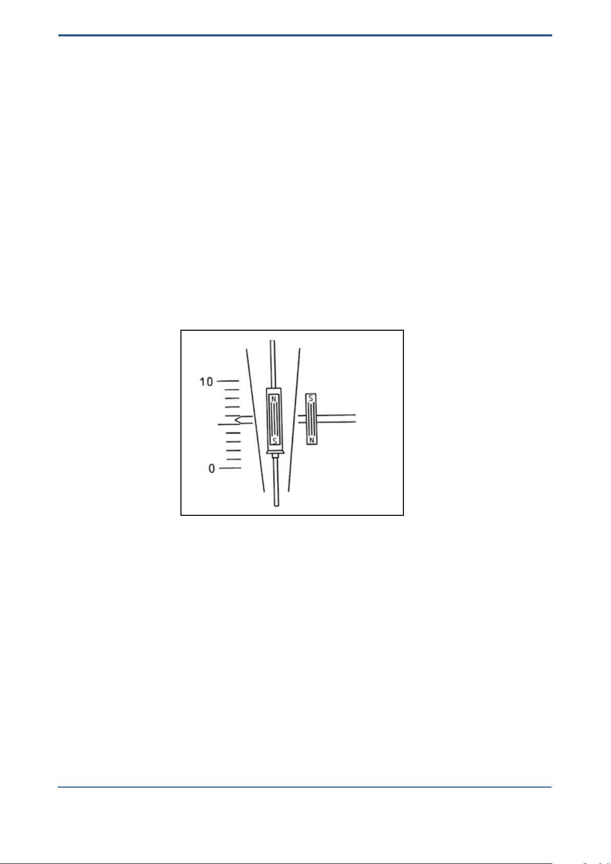
1.3 Principle of measurement
The RAMC is a Variable Area Flow Meter for volume and mass measurements of gases and liquids.
A oat, whose movement is nearly independent of viscosity is guided concentrically in a specially shaped cone.
The position of the oat is transferred magnetically to the indicator, which shows the measurement values by a
pointer on a scale. The indicator can be equipped with limit switches and an electronic transmitter.
Fig. 1-1
All units are calibrated with water by the manufacturer. By adjusting the calibration values to the measured
substance’s state of aggregation (density, viscosity), the ow rate scale for each measuring tube can be
determined.
Indication units can be exchanged without impairment of precision. However, the scale for the tube must be
mounted on the new indicator (and in case of an electronic transmitter the calibration EEPROM, too).
IM 01R01B02-00E-E 10th edition January 01, 2013 -00
All Rights Reserved. Copyright © 2003, Rota Yokogawa
Page 13
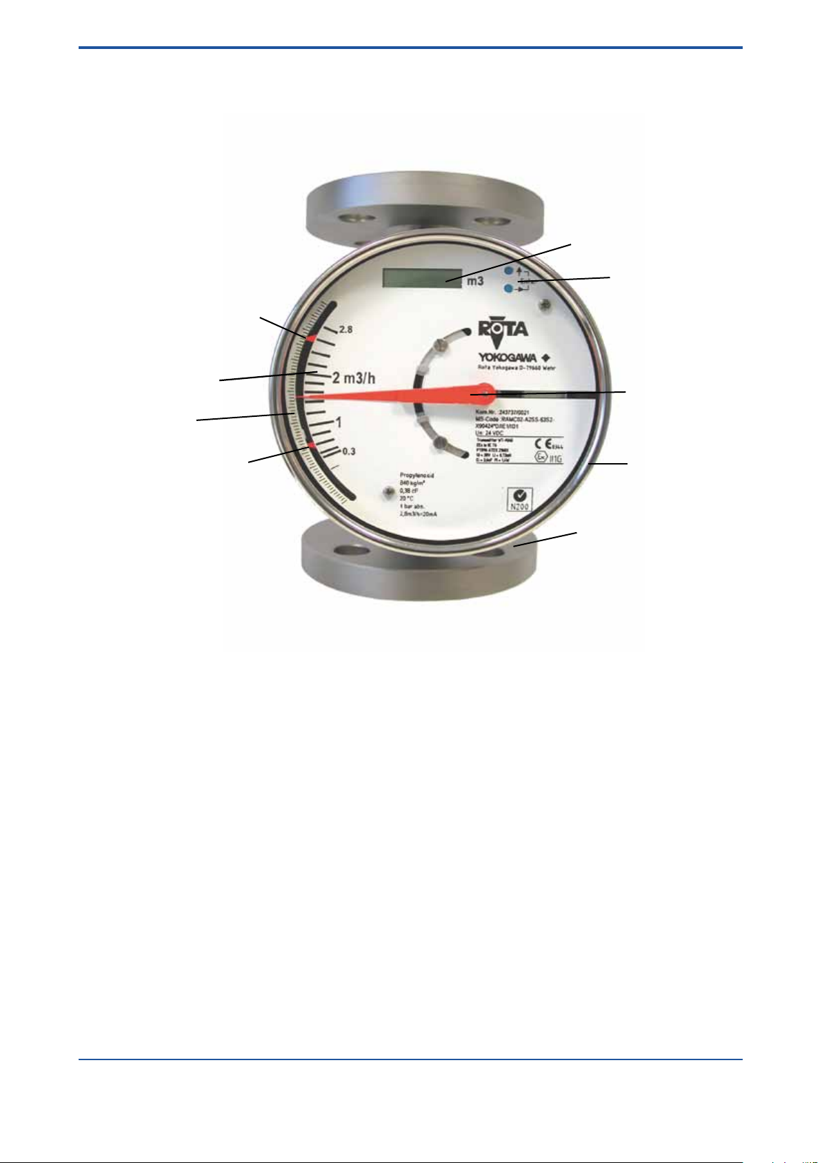
1.4 Overview
Digital display
Operation keys
Pointer
Measuring tube
Indicator
Flow scale
Limit switch MIN
Limit switch MAX
mm- scale
<1. INTRODUCTION>
1-5
Fig. 1-2
Explanations of specications on anges
- type of ange e.g. DIN
- size of ange e.g. DN15
- Pressure range of ange and measuring tube e.g. PN40
- Material of wetted parts e.g. 1.4404
- Manufacturing code of ange manufacturer
- Lot. No.
All Rights Reserved. Copyright © 2003, Rota Yokogawa
IM 01R01B02-00E-E 10th edition January 01, 2013 -00
Page 14
1-6
Tag No.: FIT...abcdefg
1.1 bar abs.
1m3/h = 20mA
1 mPas
20 Grad C
Liquide
1.1 t/m
3
E90244*D/B0/CP/K3
MS-Code: RAMC01-D4SS-43S0-
UN: 230VAC 50/60Hz 8VA
Kom.Nr.: 200000/001
Rota Yokogawa D-79660 Wehr
Transmitter WT-MAG
PTB96 ATEX 2160X
Ci = 4,16nF Ii = 101mA
PTB99 ATEX 2219X
see certificate for data
Limit Switch SC3,5-N0
Ui = 30V Li = 0,15mH Pi = 1,4W
EEx ia IIC T6
EEx ia IIC T6
II2G
0344
II2G
Enter
F11.EPS
0.1
0.5
m /h
1.0
3
3
m
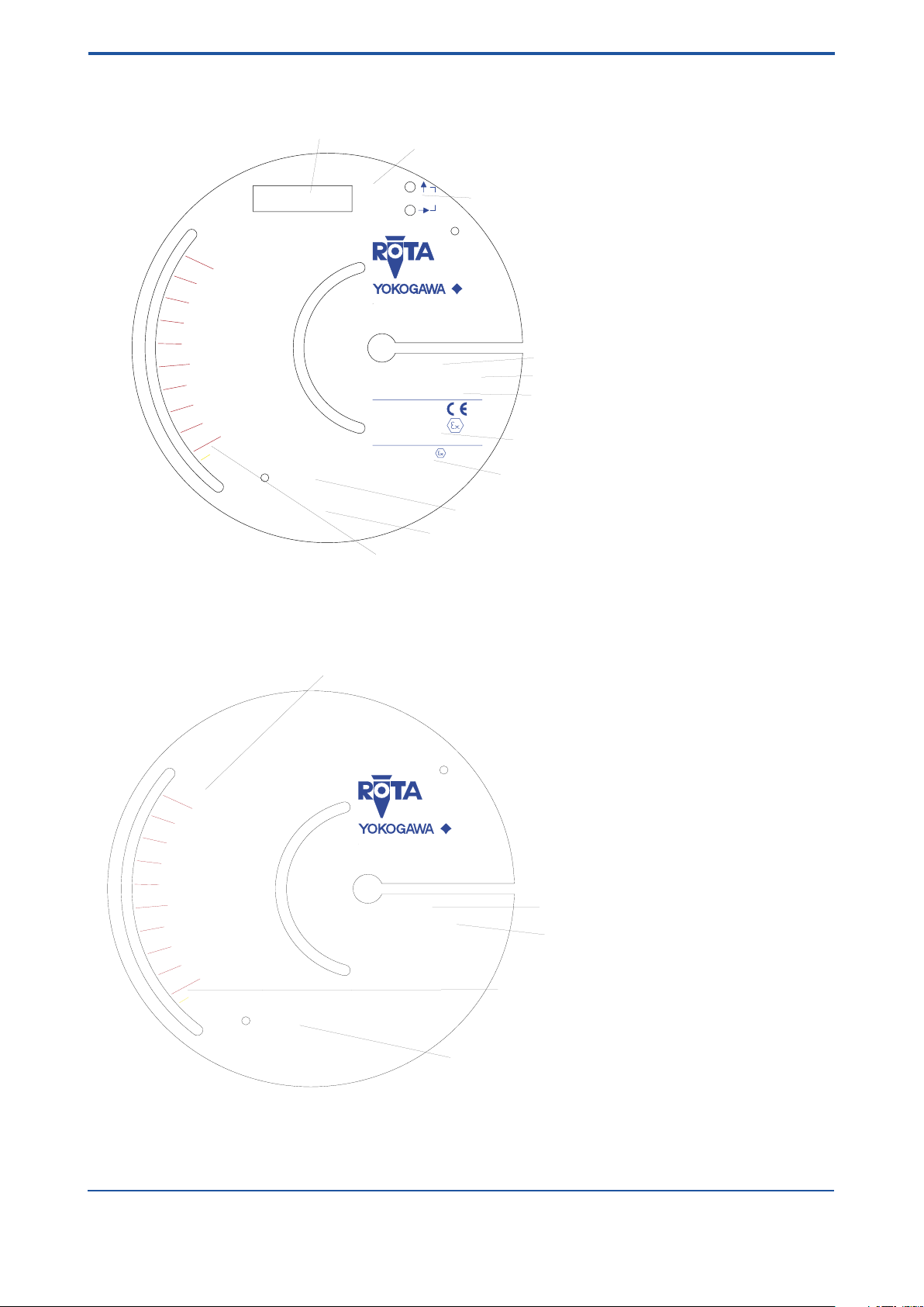
Digital Display
Engineering unit for digital display
Operation keys
Commisioning No.
Model code
Power supply
Ex-identification transmitter
Ex-identification limit switches (/K_)
Current output scaling
Medium data (fluid properties at process conditions)
Flow scale for specific fluid properties at process conditions
Tag No.: FIT...abcdefg
1.1 bar abs.
1 mPas
20 Grad C
Liquide
1.1 t/m
3
T90NNN*D
MS-Code: RAMC01-D4SS-43S0-
Kom.Nr.: 200000/001
Rota Yokogawa D-79660 Wehr
0.1
0.5
m /h
1.0
3
F12.EPS
Flow scale
Commissioning No.
Model code
Medium data (fluid properties at process conditions)
Flow scale for specific fluid properties
at process conditions
Scale examples
<1. INTRODUCTION>
Fig. 1-3 Scale example for -E / -H-type (electronic transmitter)
Fig. 1-4 Scale example for -T -type
IM 01R01B02-00E-E 10th edition January 01, 2013 -00
All Rights Reserved. Copyright © 2003, Rota Yokogawa
Page 15

<2. PRECAUTIONS>
2. Precautions
2.1 Transportation and storage
Before transporting the unit, it is recommended to x the oat with a card-board strip in the same way as
when shipped from factory. Prevent foreign objects from entering the tube (e.g. by covering openings).
To protect the unit and especially the tube’s interior from soiling, store it only at clean and dry locations
2.2 Installation
Ambient temperature and humidity of the installation location must not exceed the specied ranges. Avoid
locations in corrosive environments. If such environments are unavoidable, ensure sufficient ventilation.
Although the RAMC features a very solid construction, the instrument should not be exposed to strong
vibration or impact stress.
Please note that the RAMC’s magnetic sensing system can be inuenced by external inhomogeneous
magnetic elds (such as solenoid valves). Alternating magnetic elds (≥ 10Hz) as well as homogeneous,
static magnetic elds (in the area of the RAMC), like the geomagnetic eld have no inuence. Asymmetric
ferromagnetic bodies of considerable mass (e.g. steel girders) should be kept at a distance of at least 250 mm
from the RAMC.
To avoid interference, the distance between two adjacent RAMC must be at least 300 mm.
2-1
2.3 Pipe connections
Ensure that the bolts of the anges are tightened properly and that the gaskets are tight.
Do not expose the unit to pressures higher than the indicated maximum operating pressure (refer to
specications).
While the system is pressurized the ange bolts must not be tightened or loosened.
All Rights Reserved. Copyright © 2003, Rota Yokogawa
IM 01R01B02-00E-E 10th edition January 01, 2013 -00
Page 16

2-2
<2. PRECAUTIONS>
Blank Page
IM 01R01B02-00E-E 10th edition January 01, 2013 -00
All Rights Reserved. Copyright © 2003, Rota Yokogawa
Page 17

<3. INSTALLATION>
3-1
3. Installation
3.1 Installation in the pipeline
Be sure to remove the transport lock card-board strip from the measuring tube. Check that no cardboard
remains in the tube.
The RAMC ow rate meter must be installed in a vertical pipeline, in which the medium ows upwards.
vertical position has to be checked at the outer edge of the anges. Bigger nominal diameters (DN80/DN100)
require straight pipe sections of at least 5D in front and behind the RAMC.
The nominal diameter of the RAMC should correspond to the nominal diameter of the pipeline.
To avoid stress in the connecting pipes, the connecting anges must be aligned in parallel and axial direction.
Bolts and gaskets have to be selected according to the maximum operating pressure, the temperature range
and corrosion conditions. Centre gaskets and tighten nuts with a torque appropriate for the pressure range.
If contamination or soiling of the RAMC is to be expected, a bypass should be installed to allow the removal of
the instrument without interruption of the ow.
Please read also chapter 2.2. For further instructions on installation please refer to VDI/VDE3513.
Tightening the ange threads for RAMC with PTFE- liner with the following torques:
Nominal Size Bolts Maximum Torque
EN 1092-1 ASME B 16.5 EN 1092-1 ASME EN 1092-1 ASME 150 lbs
DN PN Inches lbs 150 lbs 300 lbs Nm ft*lbf Nm ft*lbf
15 40 ½ 150/300 4 x M12 4 x ½´´ 4 x ½´´ 9.8 7. 1 5.2 3.8
25 40 1 150/300 4 x M12 4 x ½´´ 4 x ½´´ 21 15 10 7. 2
50
80
100 16 4 150/300 4 x M16 8 x 5/8´´ 8 x ¾´´ 67 48 50 36
40 2
16
150/300 4 x M16
3 150/300
4 x 5/8´´
4 x M16 4 x 5/8´´
8 x 5/8´´ 57
8 x ¾´´
47 34
41 41
The
30
70 51
All Rights Reserved. Copyright © 2003, Rota Yokogawa
IM 01R01B02-00E-E 10th edition January 01, 2013 -00
Page 18

3-2
<3. INSTALLATION>
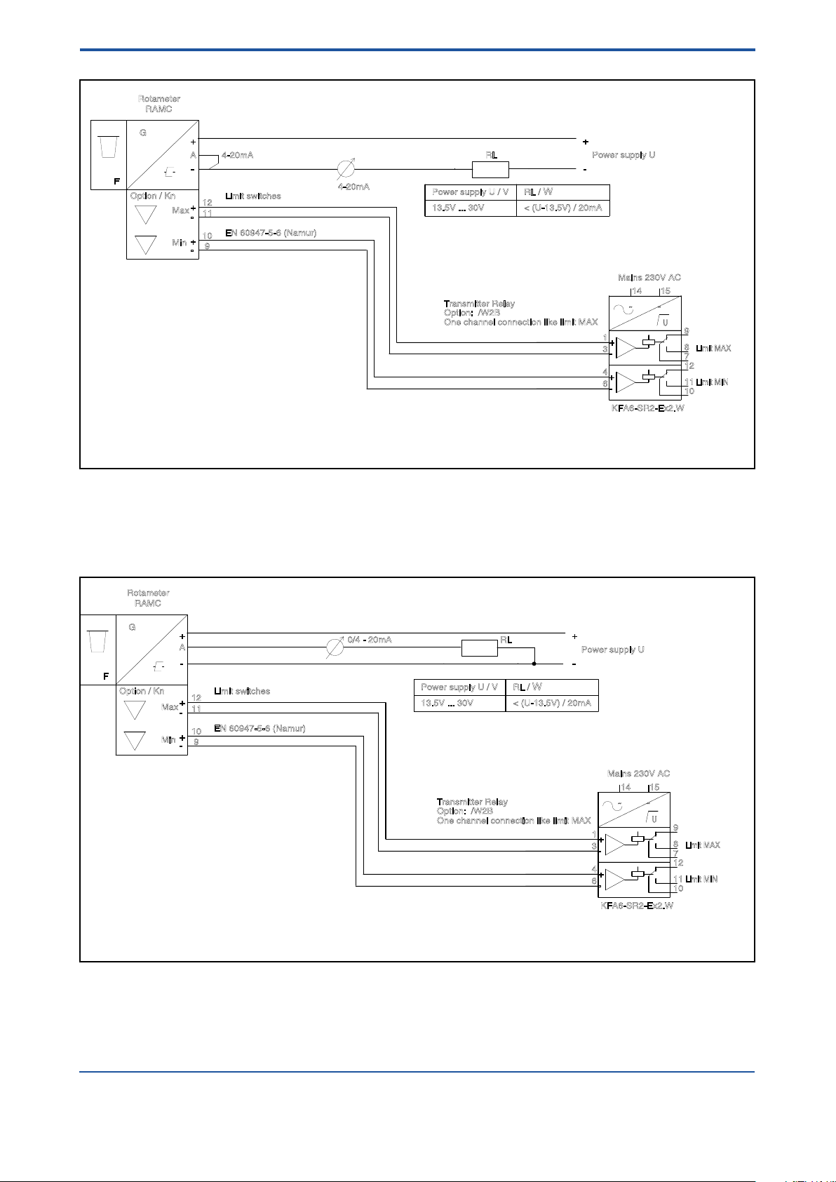
3.2 Wiring of electronic transmitter (-E, -H) and limit switches (/K_)
Please regard the drawings on the following pages.
On the rear of the RAMC are two cable glands for round cables with a diameter of 6 to 9 mm (not for Ex-d-type
option /_F1). Unused glands must be closed with a blind plug M16x1.5.
For wiring of RAMC with option /_F1 see chapter 10.9.2, 10.10.2, 10.13.2.
Wires should not be bent directly at terminal screws. Do not expose wires to mechanical pressure. Wires must
be arranged according to common installation rules, especially signal and power lines must not be bundled
together.
The RAMC terminals accept wires with a maximum sectional area of 1.5 mm2.
Measuring and indicating instruments, connected in series to the output of the electronic transmitter, must not
exceed a load impedance of
RL = (U - 13.5 V) / 20 mA — for 2-/3-wire RAMC or 500 Ω for 4-wire RAMC.
2- or 3-wire units are connected to the terminals marked “+”, “-” and “A” of the power connector.
For 2-wire instruments the terminals “-” and “A” have to be shorted with a jumper. Take care not to loose that
jumper when mounting wires.
Wiring inside the case should be kept as short as possible to avoid that moving parts are blocked.
Attention: Hints for Unit Safety (according DIN EN 61010)
- Heed the nominal voltage indicated on the scale.
- The electrical connections have to be executed according to VDE0100 “Errichten von Starkstromanlagen
mit Nennspannungen bis 1000 V” (Installation of high current assemblies with nominal voltages of up to 1000 V)
or equivalent national regulations.
- For units with a nominal voltage of 115 V or 230 V the correspondingly marked terminal has to be
connected to protective earth (PE).
- Units with a nominal voltage of 24 V may only be connected to a protected low voltage circuit (SELV-E
according to VDE0100/VDE 0106 or IEC 364/IEC 536).
- The RAMC indicator housing must be grounded to ensure electromagnetic interference protection.
This can be done by grounding the pipeline.
- This unit does not include a power switch. Therefore, a switch has to be prepared at the installation
location in the vicinity of the unit. The switch should be marked as the power separation switch for the
RAMC.
IM 01R01B02-00E-E 10th edition January 01, 2013 -00
All Rights Reserved. Copyright © 2003, Rota Yokogawa
Page 19
<3. INSTALLATION>
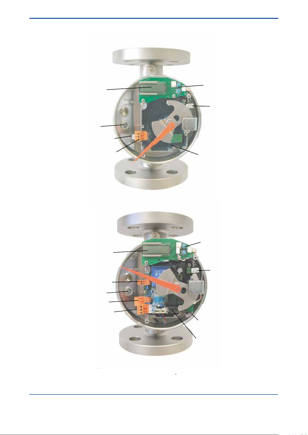
Operation keys
Calibration-EEPROM
Angle transmitter
Power supply circuit
Digital display
Pulse output (option /CP)
Current output
Mains connector
Cable gland
Operation keys
Calibration-EEPROM
Angle transmitter
Digital display
Cable gland
Power supply plug
Plug for 2-wire connection
3-3
Fig. 3-1 2-wire unit
Fig. 3-2 4-wire unit
All Rights Reserved. Copyright © 2003, Rota Yokogawa
IM 01R01B02-00E-E 10th edition January 01, 2013 -00
Page 20
3-4
15
4
6
3
1
14
12
10
11
8
7
9
U
F
G
RAMC
A
Power supply U
Mains 230V AC
KFA6-SR2-Ex2.W
Option: /W2B
Transmitter Relay
Limit MIN
Limit MAX
Option / Kn
Rotameter
4-20mA
Max
Min
12
11
10
9
Limit switches
EN 60947-5-6 (Namur)
One channel connection like limit MAX
4-20mA
RL
-
+
-
+
-
+
-
+
~ ~
+
-
+
-
Power supply U / V RL /
W
13.5V ... 30V < (U-13.5V) / 20mA
F1.EPS
15
4
6
3
1
14
12
10
11
8
7
9
U
F
G
RAMC
A
Power supply U
Mains 230V AC
KFA6-SR2-Ex2.W
Option: /W2B
Transmitter Relay
Limit MIN
Limit MAX
Option / Kn
Rotameter
Max
Min
12
11
10
9
Limit switches
EN 60947-5-6 (Namur)
One channel connection like limit MAX
0/4 - 20mA
RL
-
+
-
+
-
+
-
+
~ ~
+
-
+
-
Power supply U / V RL /
W
13.5V ... 30V < (U-13.5V) / 20mA
F2.EPS
<3. INSTALLATION>
Fig. 3-3 RAMC 2-wire unit with limit switches and transmitter relay
Fig. 3-4 RAMC 3-wire unit with limit switches and transmitter relay
IM 01R01B02-00E-E 10th edition January 01, 2013 -00
All Rights Reserved. Copyright © 2003, Rota Yokogawa
Page 21
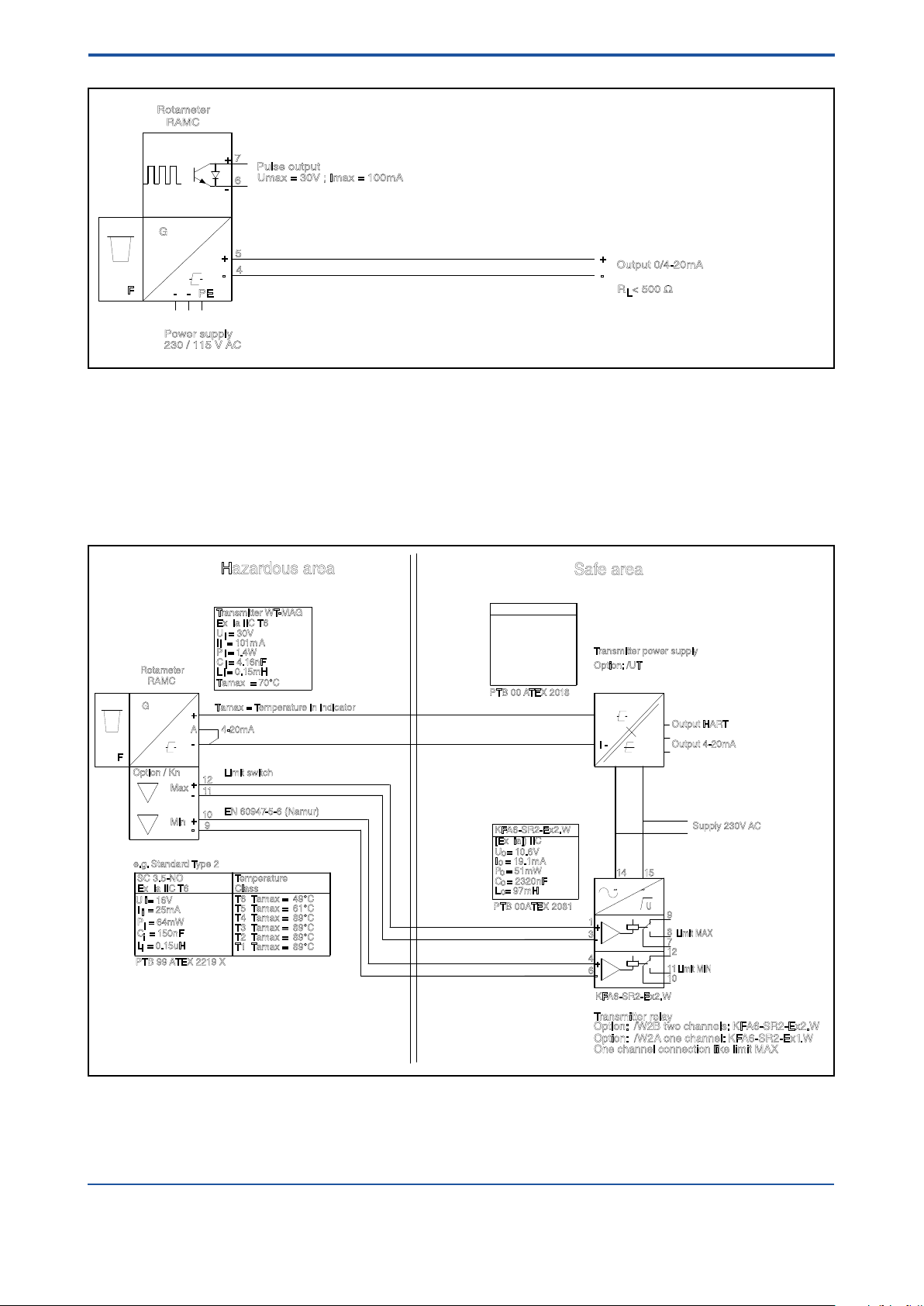
F
G
RAMC
230 / 115 V AC
4
Power supply
Output 0/4-20mA
R < 500 Ω
L
Rotameter
PE--
5
7
6
Pulse output
Umax = 30V ; Imax = 100mA
-
+
-
+
+
-
F3.EPS
Fig. 3-5 RAMC 4-wire unit with pulse output
15
4
6
3
1
14
12
10
11
8
7
9
12
11
10
9
I -
I +
L/+N/-
O -
O+
Output 4-20mA
O+H
Output HART
U
F
G
RAMC
A
Supply 230V AC
KFA6-SR2-Ex2.W
Option: /W2B two channels: KFA6-SR2-Ex2.W
Transmitter relay
Limit MIN
Limit MAX
Option / Kn
Rotameter
4-20mA
Max
Min
Limit switch
EN 60947-5-6 (Namur)
One channel connection like limit MAX
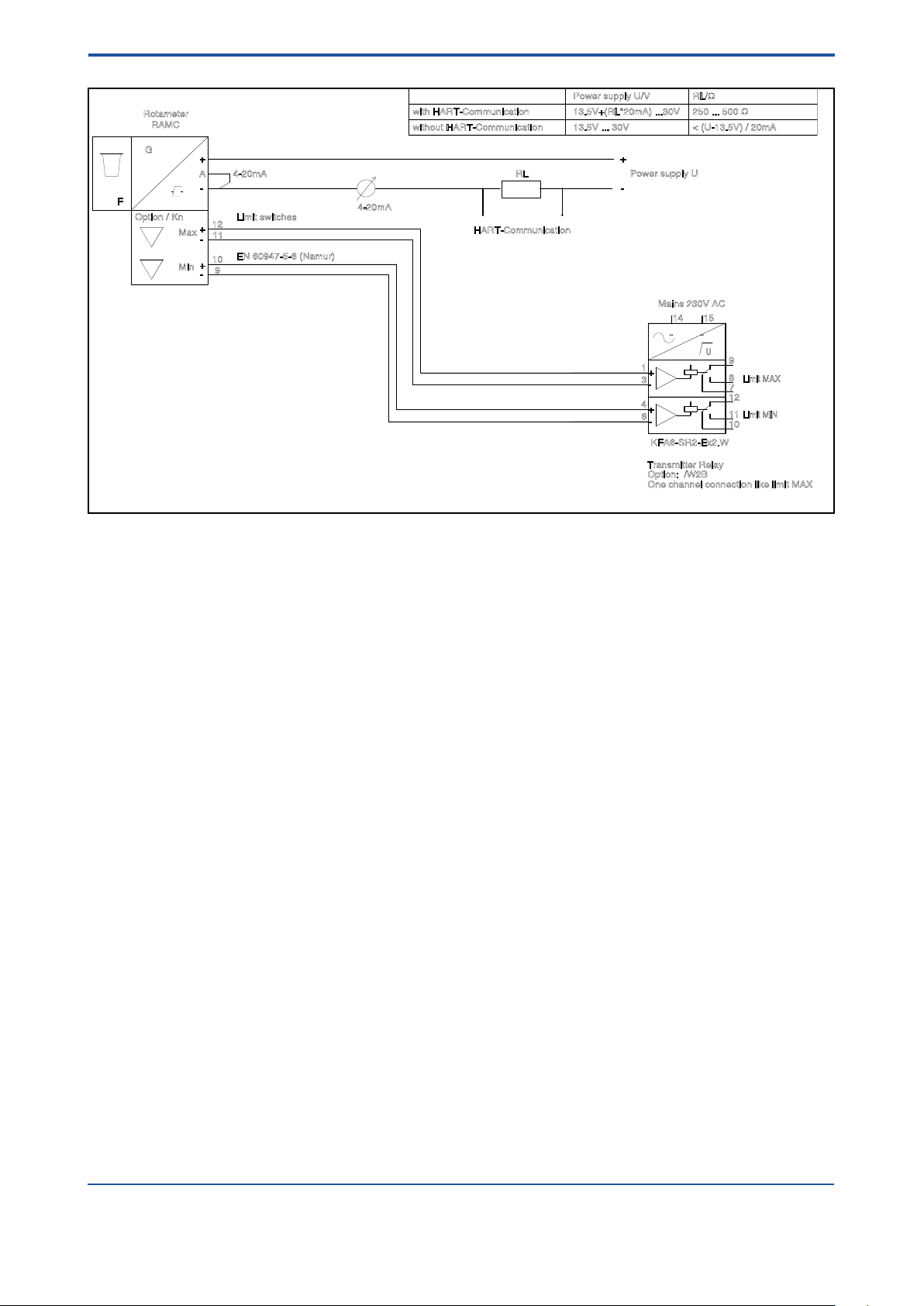
I = 101mA
P = 1.4W
C = 4.16nF
U = 30V
L = 0.15mH
Transmitter WT-MAG
Ex ia IIC T6
Gb
PTB 12 ATEX 2003
Tamax = 70°C
Tamax = Temperature in indicator
C = 150nF
Ex ia IIC T6
L
= 0.15uH
SC 3.5-NO
P = 64mW
I = 25mA
U = 16V
Temperature
T4 Tamax = 89°C
T3 Tamax = 89°C
T2 Tamax = 89°C
T1 Tamax = 89°C
Class
T5 Tamax = 61°C
T6 Tamax = 49°C
PTB 99 ATEX 2219 X
PTB 00 ATEX 2018
Transmitter power supply
Option: /UT
Option: /W2A one channel: KF A6-SR2-Ex1.W
C = 2320nF
I = 19.1mA
P = 51mW
U = 10.6V
L = 97mH
PTB 00ATEX 2081
[Ex ia]) IIC
KFA6-SR2-Ex2.W
RN221N-B1
RN221N-B1
Tamax = 50°C
C = 86nF
L = 5.2mH
U = 27.3V
P = 0.597W
[Ex ia] IIC
I = 87.6mA
o
o
o
o
o
e.g. Standard Type 2
-
+
-
+
-
+
~ ~
+
-
+
-
i
i
i
i
i
i
i
i
i
o
o
o
o
o
F5.EPS
i
Hazardous area
Safe area
<3. INSTALLATION>
3-5
Fig. 3-6 Ex-version acc. to ATEX (Option /KS1 and /KS2) : RAMC 2-wire unit with power supply,
limit switches and transmitter relay
All Rights Reserved. Copyright © 2003, Rota Yokogawa
IM 01R01B02-00E-E 10th edition January 01, 2013 -00
Page 22
3-6
15
4
6
3
1
14
12
10
11
8
7
9
U
F
G
RAMC
A
Power supply U
Mains 230V AC
KFA6-SR2-Ex2.W
Option: /W2B
Transmitter Relay
Limit MIN
Limit MAX
Option / Kn
Rotameter
4-20mA
Max
Min
12
11
10
9
Limit switches
EN 60947-5-6 (Namur)
One channel connection like limit MAX
4-20mA
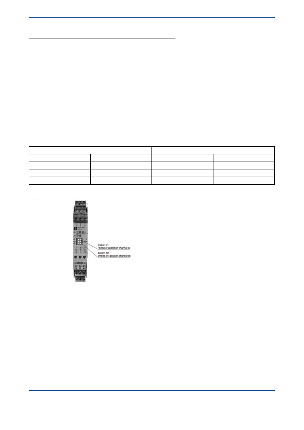
RL
HART-Communication
with HART-Communication
without HART-Communication
Power supply U/V RL/Ω
13.5V+(RL*20mA) ...30V
13.5V ... 30V < (U-13.5V) / 20mA
250 ... 500 Ω
-
+
-
+
-
+
-
+
~ ~
+
-
+
-
F4.EPS
<3. INSTALLATION>
Fig. 3-7 RAMC 2-wire unit with HART-communication, with limit switches and transmitter relay
IM 01R01B02-00E-E 10th edition January 01, 2013 -00
All Rights Reserved. Copyright © 2003, Rota Yokogawa
Page 23

<4. START OF OPERATION>
4-1
4. Start of operation
4.1 Hints on ow rate measurement
The measured uid should neither consist of a multi-phase mixture nor contain ferrite ingredients or large solid
mass particles.
The RAMC scale is adjusted to the state of operation/aggregation of the measured uid by the manufacturer. If
the state of operation changes, it might become necessary to establish a new scale. This depends on several
factors:
- If the RAMC is operated in the given viscosity independent range, only the density of the oat as well as the
operational density of the previous and new substance have to be considered. In case the operational
density only changes marginally (≤ 0.5%), the present scale can be used.
- If the RAMC is operated outside the given viscosity independent range, the viscosities at the previous and new
state of operation as well as the mass and diameter of the oat have to be taken into account.
4.2 Pulsation and pressure shock
Pressure shock waves and pulsating ow inuence measurement considerable or can destroy the meter. Surge
conditions should be avoided. (open valves slowly, raise operating pressure slowly)
If oat bouncing occurs in gases increase the line pressure until the phenomena stop. If this is not possible
provide the oat with a damper. A damping kit is available as spare part.
4.3 Start of operation of electronic transmitter
Ensure that the device has been connected correctly according to section 3-2 and that the used power supply
meets the requirements indicated on the scale.
Switch on the power supply.
The digital display gives the totalizer value in the measuring unit, indicated on the right side of the display.
The RAMC is now ready for operation.
Unit graduation, measuring unit, damping, etc. can be adjusted by an operating menu (refer to section 6.2). In
case of an error, the bars beneath the 8 digits of the display will ash. The corresponding error message can
be checked using the operating menu and then taking the appropriate counter measures (refer to section
6-2-8 “Error Messages”).
The transmitter has been prepared and calibrated according to the model code as a 2-, 3- or 4-wire unit.
In 2-wire units, a jumper connects “A” and “-”. When switching from a 2- to a 3-wire conguration, this jumper
should be removed. The current output should then be adjusted as explained in section 6-2-6.
When changing from a 3- to 2-wire conguration, the jumper should be set in place, and the current output
has to be adjusted according to section 6-2-6.
All Rights Reserved. Copyright © 2003, Rota Yokogawa
IM 01R01B02-00E-E 10th edition January 01, 2013 -00
Page 24

4-2
<4. START OF OPERATION>
Blank Page
IM 01R01B02-00E-E 10th edition January 01, 2013 -00
All Rights Reserved. Copyright © 2003, Rota Yokogawa
Page 25
<5. LIMIT SWITCHES OPTION /K[]>
5-1
5.
The optional limit switches are available as maximum or minimum type switches. They are proximity switches
according to EN 60947-5-6 (NAMUR). Maximal two switches can be installed. The option (/Wnn) includes the
respective transmitter relay.
These switches have been specied for hazardous area. However, the transmitter relay must be installed
in safe area.
The limit switches are connected to the transmitter relays as indicated in chapter 3.2.
The terminals for the limit switches are on a small board on top of the transmitter case.
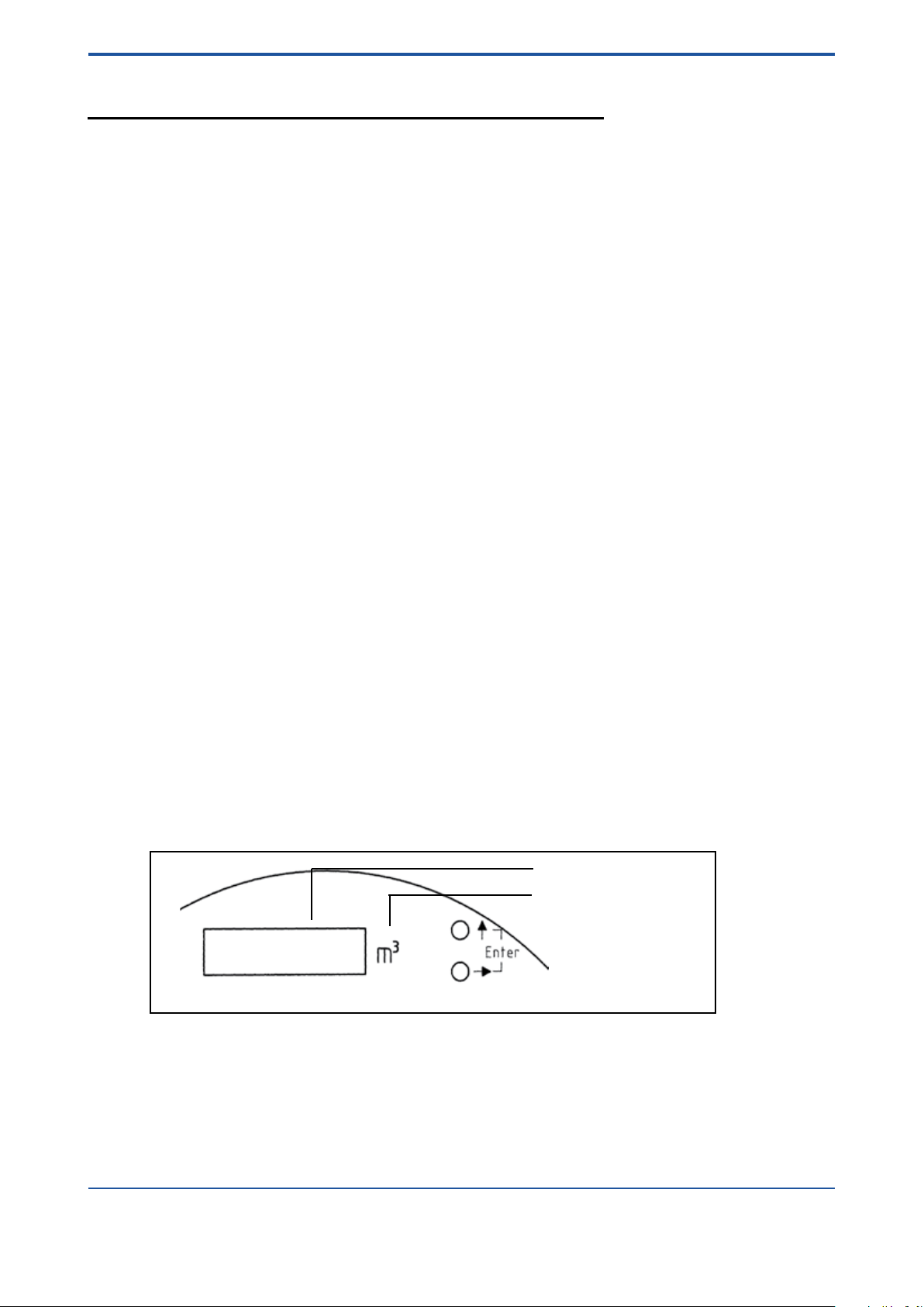
Use of 2 standard limit switches (option /K3):
The MIN-MIN and MAX-MAX functions have been integrated at the factory as MIN-MAX switches in the RAMC.
The MIN-MIN or MAX-MAX function is set by adjusting the switching direction of the transmitter relay. The
concerning 2- channel transmitter relays are:
Option /W1B: KFA5-SR2-Ex2.W
Option /W2B: KFA6-SR2-Ex2.W
Option /W4B: KFD2-SR2-Ex2.W
The following table shows the assignment:
Limit switches (Option /K[])
Function Switching direction of transmitter relay *
Channel 1 Channel 2 Channel 1 Channel 2
MIN MAX S1 position I S2 position I
MIN MIN S1 position I S2 position II (ON)
MAX MAX S1 position II (ON) S2 position I
* see following gure for S1 and S2 on transmitter relay.
Use of Fail Safe limit switches (option /K6 ... /K10):
For Fail Safe application only 1- channel transmitter relays are available.
Option /W2E: KHA6-SH-Ex1.W
Option /W2F: 2 x KHA6-SH-Ex1.W
Option /W4E: KFD2-SH-Ex1.W
Option /W4F: 2 x KFD2-SH-Ex1.W
If other transmitter relays are used as the above mentioned types, the transmitter relay has to be applied
as protection technology to ensure functional safety.
Please notice chapter 9.3 "Standard specications".
For questions regarding protection technology, please consult your YOKOGAWA service center.
All Rights Reserved. Copyright © 2003, Rota Yokogawa
IM 01R01B02-00E-E 10th edition January 01, 2013 -00
Page 26

5-2
<5. LIMIT SWITCHES OPTION /K[]>
Blank Page
IM 01R01B02-00E-E 10th edition January 01, 2013 -00
All Rights Reserved. Copyright © 2003, Rota Yokogawa
Page 27
<6. ELECTRONIC TRANSMITTER (-E)>
F61.EPS
Digital display
Engineering unit of the display
Operation keys
6-1
6. Electronic Transmitter (-E)
6.1 Operation principle
The position of the oat is magnetically transferred to a magnetic follow up system. The position angle of this
magnetic rocker is detected by magnet sensors. A micro controller determines the angle by means of a
combining reference value table in the memory and calculates the ow rate by the angle with calibration and
operation parameters the calibration EEPROM. The ow rate is given as a current, either 0-20 mA or 4-20 mA,
and, in addition, indicated on the digital display (refer also to section 6-2). The electronic transmitters have been
electronically adjusted before shipping and, therefore, are mutually exchangeable.
Calibration data of the metering tube as well as customer specic data are entered into a calibration EEPROM,
inserted on the board. This calibration EEPROM and the indication scale are assigned to the respective
metering tube.
When replacing an indicator (e.g. because of a defect) the scale and calibration EEPROM of the old unit have
to be inserted in the new unit. Then, no calibrations or adjustments are necessary.
If an indicator with electronic transmitters is installed to a new metering tube, the calibration EEPROM of that
tube has to be inserted into the transmitter and the indicator scale for that particular tube has to be mounted.
A change in the uid data (e.g. specic gravity, pressure, etc.) requires the preparation and mounting of
a new calibration EEPROM and scale.
Normally the range of the current output is equal to the rounded measuring range of the tube (end value on
scale). The customer can position the 20 mA point between 60% and 100% of the end value on scale. The set
of the 20 mA point is shown on the scale (refer to Fig. 1-4). The ow cut off is positioned at 5% of the end value.
Below 5% ow the current output shows 0 mA (4 mA).
6.2 Parameter setting
The displays allows indication of various parameters:
• Flow rate (8 mass or volume units in combination with 4 time units)
• Counter (8 mass or volume units)
• Flow rate indication in percent
• Special functions:
• Setting of different damping times
• Switching of current output 0-20 mA / 4-20 mA or vice versa
• Indication of error messages
• Manual adjustment
• Service functions
• Detection of oat blockage
The setting of these parameters is done by two buttons.
Fig. 6-1 Operation keys
All Rights Reserved. Copyright © 2003, Rota Yokogawa
IM 01R01B02-00E-E 10th edition January 01, 2013 -00
Page 28

6-2
<6. ELECTRONIC TRANSMITTER (-E)>
The buttons access three functions:
- upper button ( ↑ ) : Exit setting mode
- lower button ( → ) : Scroll through menu/selection of parameters
- both buttons ( ↑ + → ) = Enter : Entering parameters/selecting setting mode
If no button is pressed for one minute while the operating menu is active, the indication reverts to the
measuring indication. This does not apply to subfunctions F32, F33, F52, F63.
For indication of volume or mass values at maximum 6 digits in front of the decimal point and 7 decimals are
used. This format allows an indication range for ow rates from 0.0000001 unit/time to 106000 unit/time. Flow
rate values exceeding 106000 are shown as ‘————’ on the display. In this case the next bigger ow rate unit
(next smaller time unit) has to be selected.
For the indication of totalizers values 8 digits are used at maximum of which 7 digits can be assigned for
decimal values. The decimal point setting is determined by selecting the unit. Therefore, possible totalizer
offsets are:
Unit *1
Unit *1/10
Unit *1/100
The totalizer counts up to 99999999 or 9999999.9 or 999999.99 and is reset to zero.
The next page shows the operating menu.
The following describes selection and execution of functions.
Menue :
Indication meas .val F1- : Indication F11 : Selection F11-1 : Flow rate
F11-2 : Totalizer
F11-3 : %
F11-4 : Temperature
Euro / US
F12 : Flow rate unit F12-1 : m³ / m³
F12-2 : l / acf
F12-3 : Nm³ / Nm³
F12-4 : NL / scf
F12-5 : t / ton
F12-6 : kg / kg
F12-7 : scf / lb
F12-8 : gal / usg
Euro / US
F13 : Time unit F13-1 : h / h
F13-2 : min / min
F13-3 : s / s
F13-4 : day / day
F14 : Reset Totalizer F14-1 : Execute
F2- : Damping F21 : Selection F21 0 : 0 s
IM 01R01B02-00E-E 10th edition January 01, 2013 -00
F15 : Temperature unit F15-1 : degC
F15-2 : DegF
F21 1 : 1 s
F21 5 : 5 s
F21 10 : 10 s
All Rights Reserved. Copyright © 2003, Rota Yokogawa
Page 29

<6. ELECTRONIC TRANSMITTER (-E)>
F3- : Output F31 : Selection F31 0-20 : 0-20 mA
F31 4-20 : 4-20 mA
F32 : Offset adjustment F32 00
F33 : Span adjustment F33 00
F34 : Pulse output *) F34-1 : not active
F34-2 : last digit
F34-3 : last but one digit
F4- : Error messages F41 : Indication F41 Enn
F5- : Manual calibr. F51 : On/Off F51-1 : off
F51-2 : on
F52 : Calibration table F52 5 : 5% point
F52 15 : 15% point
F52 25 : 25% point
F52 35 : 35 point
F52 45 : 45% point
F52 55 : 55% point
F52 65 : 65% point
F52 75 : 75% point
F52 85 : 85% point
F52 95 : 95% point
F52 105 : 105% point
6-3
F6- : Service F61 : Revision indicatior H.. F..
F62 : EEPROM revision A.. C..
F63 : Current output test F63 04 : 0 or 4 mA
F63 20 : 20 mA
F64 : Calibration table F64-1 : Standard
F64-2 : Remote version
F65 : Master Reset F65-1 : Execute
F7- : Float Block. Ind. F71 : Off/On F71-1 : Off/On
F71-2 : On/Off
F72 : Lower limit F72-1 : 5% of Qmax
F72-2 : 15% of Qmax
F72-3 : 30% of Qmax
F73 : Supervision time F73-1 : 5 Minutes
F73-2 : 15 Minutes
F74 : Autozero F74-1 : Execute
Bold type = Factory Pre-setting
*) Option /CP
All Rights Reserved. Copyright © 2003, Rota Yokogawa
IM 01R01B02-00E-E 10th edition January 01, 2013 -00
Page 30

6-4
<6. ELECTRONIC TRANSMITTER (-E)>
6.2.1 Selection of indication function (F11)
The function F11 selects the display’s indication function.
The following indications can be set: ow rate, totalizer, % value or temperature.
At the factory the display is preset to totalizer indication.
Description Selection Key Indication
Display mode
Change to setting mode Enter
Setting function
Selection
or
or
or
Back to display mode
Note: If you press “↑” instead of “Enter”, you can return from the selected point to the previous menu without
activating the displayed parameter.
Flow rate
Totalizer
%
Temperature
Enter
Enter
Enter
→
Enter
2 x →
Enter
3 x →
Enter
↑
↑
F1-
F11
F11 -1
F11
F11 -2
F11
F11 -3
F11
F11 -4
F11
F1-
Display mode
When selecting “Flow rate” the measuring unit is set with function F12 and F13. When selecting “Totalizer” the
measuring unit is set with F12. If % indication is selected, F12 and F13 have no effect. The internal totalizer is
updated, if “Flow rate” or “Counter” is selected. In case of setting to “%” the internal counter is not updated
and keeps its previous value.
If "Temperature" is selected the unit can be set by function F15. The indicated value is the temperature in the
indication unit.
After changing the indicating function and measuring units the corresponding measuring unit label should be
xed on the right side next to the display.
IM 01R01B02-00E-E 10th edition January 01, 2013 -00
All Rights Reserved. Copyright © 2003, Rota Yokogawa
Page 31

<6. ELECTRONIC TRANSMITTER (-E)>
6-5
6.2.2 Setting the unit (F12 / F13)
When ordering the transmitter two sets of metering units are available. It is not possible to switch between them.
These two sets comprise the following metering units:
European unit set, Standard
Standard Description Unit Menu / Index
Flow rate unit SI
SI
SI
SI
SI
SI
---
---
Time unit SI
SI
SI
---
Cubic meter
Liter
Norm cubic meter
(0°C; 1 Atm.abs = 1.013 bar
Norm Liter
To n
Kilogram
Standard cubic feet
(21°C; 1Atm.abs = 1.013 bar
Gallon (imperial, UK)
Hour
Minute
Second
Day
m³
l
Nm³
Nl
t
kg
scf
gal
h
min
s
d
-1
-2
-3
-4
-5
-6
-7
-8
-1
-2
-3
-4
US unit set, Option /A12
Standard Description Unit Menu / Index
Flow rate unit SI
--SI
---
--SI
---
---
Time unit SI
SI
SI
---
Cubic meter
Actual cubic feet
Norm cubic meter
(32°F; 1 Atm.abs = 14.69 psi
Standard cubic feet
(70°F; 1Atm.abs = 14.69 psi
Long ton
Kilogram
Pound
Gallon (US)
Hour
Minute
Second
Day
m³
acf
Nm³
scft
ton
kg
lb
usg
h
min
s
d
-1
-2
-3
-4
-5
-6
-7
-8
-1
-2
-3
-4
All Rights Reserved. Copyright © 2003, Rota Yokogawa
IM 01R01B02-00E-E 10th edition January 01, 2013 -00
Page 32

6-6
<6. ELECTRONIC TRANSMITTER (-E)>
With functions F12 and F13, the measuring unit for displayed value is selected.
F12 selects volume and mass units, while F13 sets the corresponding time unit.
When selecting the indication function “totalizer” the set time unit is not taken into account and only the
selected mass or volume unit is effective. When choosing the “%” indication F12 and F13 have no effect.
The selection of the measuring unit is performed as follows:
Description Selection Key Indication
Display mode
Change to setting mode Enter
Setting
Masse/Volume unit unit set
Euro US
Selection unit
or
m3 m3
l acf
Enter
→
Enter
Enter
→
Enter
or
Nm3 Nm3
2 x →
Enter
or
Nl scf
3 x →
Enter
or
t ton
4 x →
Enter
or
kg kg
5 x →
Enter
or
scf lb
6 x →
Enter
gal usg
7 x →
Enter
Setting
Time unit
Selection time unit
or
h h
min. min
→
Enter
Enter
→
Enter
or
s s
2 x →
Enter
or
day day
3 x →
Enter
Back to display mode
↑
↑
F1-
F11
F12
F12 -1
F12
F12 -2
F12
F12 -3
F12
F12 -4
F12
F12 -5
F12
F12 -6
F12
F12 -7
F12
F12 -8
F12
F13
F13 -1
F13
F13 -2
F13
F13 -3
F13
F13 -4
F13
F1-
Display mode
Note: If you press “↑" instead of “Enter”, you can return from the selected point to the previous menu
without activating the displayed parameter.
After changing the measuring unit the corresponding measuring unit label should be xed on the right side
next to the display. A sheet with stickers is included.
Attention: When switching the mass/volume unit the totalizer is reset to zero.
When changing the time unit the totalizer value remains unchanged.
IM 01R01B02-00E-E 10th edition January 01, 2013 -00
All Rights Reserved. Copyright © 2003, Rota Yokogawa
Page 33

<6. ELECTRONIC TRANSMITTER (-E)>
6.2.3 Totalizer reset (F14)
Function F14 resets the totalizer to zero.
The counter reset is performed as follows:
Description Selection Key Indication
Display mode
Change to setting mode Enter
Setting mode Enter
3 x →
Enter
Selection Reset Enter F14
Back to display mode
Note: If you press “↑" instead of “Enter”, you can return from the selected point to the previous menu
without activating the displayed parameter.
↑
↑
F1-
F11
F14
F14 -1
F1-
Display mode
6.2.4 Selection of temperature unit (F15)
The function F15 sets the unit of temperature indication.
The following indications can be set : degC (Celsius) or degF (Fahrenheit).
At the factory the display is set to degC indication.
The selection of the indication is as follows :
Description Selection Key Indication
Display mode
Change to setting mode Enter
Setting mode Enter
4 x →
Enter
Selection degC
degF
Back to display mode
Enter
→
Enter
↑
↑
F1-
F11
F15
F15 -1
F15
F15 -2
F15
F1-
Display mode
6-7
Note: If you press “↑" instead of “Enter”, you can return from the selected point to the previous menu
without activating the displayed parameter.
All Rights Reserved. Copyright © 2003, Rota Yokogawa
IM 01R01B02-00E-E 10th edition January 01, 2013 -00
Page 34

6-8
<6. ELECTRONIC TRANSMITTER (-E)>
6.2.5 Setting of damping (F2-)
Function F21 allows damping the output with a certain time constant (63% value). Normally the time constant
is set to 1 sec.
The selection of the time constant is as follows:
Description Selection Key Indication
Display mode
Change to setting mode Enter
Setting mode →
Enter
Selection damping
constant
or
or
or
Back to display mode
Note: If you press “↑" instead of “Enter”, you can return from the selected point to the previous menu
without activating the displayed parameter.
0 s
1 s
5 s
10 s
Enter
Enter
→
Enter
2 x →
Enter
3 x →
Enter
↑
↑
F1-
F2F21
F21 0
F21
F21 1
F21
F21 5
F21
F21 10
F21
F2-
Display mode
6.2.6 Selection / Adjustment 4-20 mA / 0-20 mA (F3-)
Function F3- sets the current output to 4-20 mA or 0-20 mA. In addition, offset and span have to be
readjusted. Offset compensation is for ne tuning the 0 or 4 mA point. Span or range compensation is for
precise adjustment of the 20 mA point.
For compensating the output, an ampere metre (mA) should be connected to the circuit loop. For wiring refer
to the diagrams in chapter 3.
The current output is set according to customer specications at the factory.
Switching the output is executed as follows:
Description Selection Key Indication
Display mode
Change to setting mode Enter
Setting mode
Output selection
Selection
or
Setting function
Offset-Adjustment
Offset-Adjustment
(Setting current to 0/4 mA)
Setting function
Span setting Enter
Span setting
(Setting current to 20 mA)
Back to display mode
0-20
4-20
Increase
Decrease
if 0/4 mA
Increase
Decrease
if 20 mA
2 x →
Enter
Enter
Enter
→
Enter
→
Enter
↑
→
Enter
↑
→
Enter
↑
↑
F1-
F3F31
F31 0-20
F31
F31 4-20
F31
F32
F32 00
F32 in steps of +1 (+20 µA)
F32 in steps of -1 (-20 µA)
F32
F33
F33 0
F33 in steps of +1 (+20 µA)
F33 in steps of -1 (-20 µA)
F33
F3-
Display mode
IM 01R01B02-00E-E 10th edition January 01, 2013 -00
All Rights Reserved. Copyright © 2003, Rota Yokogawa
Page 35

<6. ELECTRONIC TRANSMITTER (-E)>
WARNING
An adjusting step corresponds to 20 µA. The complete adjusting range is ± 0.62 mA (31 steps). If the
adjusting range does not suffice, change to display F32 or F33 by pressing ENTER when display shows F32
31 or F33 31, press ENTER again and continue adjusting at F32 00 or F33 00.
3 wire connection:
At this the ranges 0-20 mA and 4-20 mA are possible. At a switch over between the two ranges with F31 the
current output is automatically adjusted at equipment as of rmware version 1.4 . (s.F 61). A perhaps
necessary ne adjustment can be carried out with F32 or F33.
2 wire connection:
At this only the range of 4-20 mA is meaningful. The range of 0-20 mA is not closed however. At the change
to 0-20 mA with F31 the equipment assumes a remodelling on 3 wire connection and the current output is
adjusted according to this. A perhaps necessary ne adjustment can be carried out with F32 or F33.
Since YOKOGAWA doesn’t have any inuence on the custom-designed connection the current output is not
automatically adapted, if the connection is changed from 2 wire to 3 wire or vice versa .This must be manually
carried out with the functions F32 and F33.
Preset values :
Connection
Current range
0 - 20 mA --------- I0 = 0 mA
4 - 20 mA I4 = 0.4 mA + 3.6 mA
I20 = 16.4 mA + 3.6 mA
Note Do not use F31 Use F31 for changing
2- wire 3-wire
I20 = 20 mA
I0 = 4 mA
I20 = 20 mA
6-9
6.2.7 Pulse output (F34) (Option /CP)
With the function F34 the optional pulse output can be activated and adjusted.
Description Selection Key Indication
Change to setting mode Enter
Setting mode 2 x →
Enter
3 x →
Selection
or
or
Back to display mode
Activation
Resolution last digit
Resolution last but one digit
Enter
Enter
→
Enter
2 x →
Enter
↑
↑
Display mode
F1-
F3F31
F34
F34 -1
F34
F34 -2
F34
F34 -3
F34
F3-
Display mode
All Rights Reserved. Copyright © 2003, Rota Yokogawa
IM 01R01B02-00E-E 10th edition January 01, 2013 -00
Page 36

6-10
F62.EPS
RAMC Powersupply board
control unit
<6. ELECTRONIC TRANSMITTER (-E)>
6.2.7.1 General
The volume totalizer function in the electronic transmitter is available with a potential free
pulse contact.
The connection is supported only at 4-wire-units on the power supply at pins 6, 7.
The pulse output is activated and selected by function F34 in the menu structure.
Two different pulse rates can be selected. The lower pulse rate (higher solution) corresponds to the last (least
signicant) digit of the totalizer. The higher pulse rate (lower solution) corresponds to the last but one digit of
the totalizer.
6.2.7.2 Connection
6.2.7.3 Adjustments
The function F34 is added to the menu structure.
With the selection of F34 -1 the pulse output is switched off. With the selection of the functions F34 -2 or F34 -3
the pulse output is activated with the concerning solution.
· F34 -1 not active
· F34 -2 last totalizer digit
· F34 -3 last but one totalizer digit
Special case : If Qmax is higher than 10000, the pulse rate is increased by factor 10 in both cases.That means:
· F34 -2 last but one totalizer digit
· F34 -3 third totalizer digit from the right
IM 01R01B02-00E-E 10th edition January 01, 2013 -00
All Rights Reserved. Copyright © 2003, Rota Yokogawa
Page 37

<6. ELECTRONIC TRANSMITTER (-E)>
NOTE
6-11
6.2.7.4 Calculation of pulse rate
Concerning the nal ow-value (Qmax ), which was declared in the customers order, the pulse rate is
calculated in factory and is written onto the sheet ´Data of Pulse Output (Option /CP)´, which is included. This
value can be transferred to a blank label of the also included sheet with unit-stickers and then xed on the
scale. After changing the ow rate unit with F12 the pulse rate must be recalculated.
Calculation of pulse rate :
· Read the value of Qmax from the scale or recalculate it.
· Search for the concerning range in the rst row of the table below.
· Read the concerning pulse rates in the second and third row.
· The measuring unit is equal to the ow
Maximum ow Qmax
without unit
Qmax ≤ 1
1 < Qmax ≤ 10
10 < Qmax ≤ 100
100 < Qmax ≤ 1000
1000 < Qmax ≤ 10000
10000 < Qmax ≤ 100000
0.0001
0.001
0.01
0.1
1
10
Pulse rate for F34-2
without unit
Pulse rate for F34-3
without unit
0.001
0.01
0.1
1
10
100
e.g..: Final value (Qmax ) = 400 m3/h
→ Pulse rate 0.1 m3 for F34-2 and 1 m3 for F34-3
• The factory default is F34 -2 (solution : 1 last digit).
• After Master Reset F34 -1 (Pulse output not active) is selected.
• After changing the ow rate unit with F12 the pulse-register is deleted and the pulse rate is automatically
redened according to the new unit.
• After totalizer Reset with F14 the pulse output does not change.
• When changing the indication with F11 -3 to ´%´, the totalizer stops and the pulse output is switched off.
• After switching power on one pulse is generated at the output.
• For 2- respectively 3-wire-units the function F34 is not supported.
All Rights Reserved. Copyright © 2003, Rota Yokogawa
IM 01R01B02-00E-E 10th edition January 01, 2013 -00
Page 38

6-12
<6. ELECTRONIC TRANSMITTER (-E)>
6.2.8 Error messages (F4-)
If the 8 bars beneath the digits start ashing, an error has occurred in the measuring transmitter/current
output. Since the pointer indication is independent from the electric measuring transmitter, it may show the
correct measuring value even if the transmitter is defective. Function F41 allows checking of assigned error
codes.
Error codes are called onto the display as follows:
Description Selection Key Indication
Display mode
Change to setting mode Enter
Setting mode 3 x →
Enter
Enter
Enter
Back to display mode
List of error messages :
Code Meaning Remedy
01
02
03
04
05
06
07
08
RAM-error
ADC-error
Internal EEPROM faulty
Calibration-EEPROM faulty
Wrong totalizer value in EEPROM
Overow (ow rate too high)
Internal EEPROM faulty
Float blocking indication realized,
supervision time gone off
Indication unit needs service
Indication unit needs service
Indication unit needs service
If EEPROM is missing insert, -otherwise order new
EEPROM
Reset totalizer
Reduce ow rate
Indicator unit needs service
Deactivate oat-blocking-indication or run Autozero
function
↑
↑
F1-
F4F41
F41 Enn
F41
F4-
Display mode
In case of error the appropriate remedy has to be taken.
IM 01R01B02-00E-E 10th edition January 01, 2013 -00
All Rights Reserved. Copyright © 2003, Rota Yokogawa
Page 39

<6. ELECTRONIC TRANSMITTER (-E)>
NOTE
6-13
6.2.9 Manual adjustment (F5-)
During manufacturers adjustment and calibration process the relation between ow rate with water (or with air)
and oat position (indicated as angle on the mm-scale) is determined. Based on the properties of the customers
uid at expected operating conditions the ow scale and the corresponding EEPROM is then
calculated.
If the uid properties are changing (by change of the uid or by change of the process conditions) the scale as
well as the EEPROM has to be adapted. Easiest and recommended way to do this is to order new scale and
EEPROM for the new properties from manufacturer and to replace both.
A second possibility is to readjust the meter by the user. This readjustment procedure will only adjust the current
output and the display indication (but only in % of the new ow range), At least the readjustment by the user is
possible by two different procedures:
1 Manual “dry” readjustment based on recalculated original scale:
The following steps have to be performed:
1.a ) Calculate the new of ow rate to mm (on scale) relation based on original manufacturers calibration
certicate.
1.b ) Place the RAMC (with the measuring tube) horizontally on a table (Note: the distance to any ferro magnetic parts must be at least higher then 25 cm!).
1.c ) Go to menu function F51 and press ENTER to switch to manual adjustment mode. (Switching back
to the original adjustment is possible by pressing ENTER again).
1.d ) Go to menu function F52 in order to start the manual adjustment.
1.e ) Move the oat to a position where the pointer is indicating on mm-scale the mm-value belonging to
5% of the new ow rate (Note: these values have to be calculated in step a rst!)
1.f ) Press ENTER to adjust the rst 5% point.
1.g ) Repeat steps 1.e) to 1.f) for the 15%; 25%; 35%; 45%; 55%; 65%; 75%; 85%; 95% and 105%
points. (Note: The whole loop from 5% to 105% has to be adjusted in the requested order without
interruption. It is not possible to skip or stop and restart the adjustment.)
1.h ) The adjustment has to be nished and stored by pressing “ ↑ “.
After storage the new adjustment is permanently available and can be switched “on” or “off” by function F51.
When manually adjustment is active, the user is responsible for the measurement accuracy.
Activating/deactivating manual adjustment table (F51)
Description Selection Key Indication
Display mode
Change to setting mode Enter
Setting mode 4 x →
Enter
Selection
Change state
Take state
Back to display mode
(*) -1 : manual adjustment OFF; -2 : manual adjustment ON
Enter
→
Enter
↑
↑
F1-
F5F51
F51 -1 or -2 (*)
F51 -2 or -1
F51
F5-
Display mode
All Rights Reserved. Copyright © 2003, Rota Yokogawa
IM 01R01B02-00E-E 10th edition January 01, 2013 -00
Page 40

6-14
<6. ELECTRONIC TRANSMITTER (-E)>
Input of manual adjustment table (F52)
The manual adjustment table is input as follows:
Description Selection Key Indication
Change to setting mode Enter
Setting mode 4 x →
Enter
→
Selection
5%- point
15%- point
25%- point
35%- point
45%- point
55%- point
65%- point
75%- point
85%- point
95%- point
105%- point
Enter
Enter
Enter
Enter
Enter
Enter
Enter
Enter
Enter
Enter
Enter
Enter
Back to display mode
Display mode
F1-
F5F51
F52
F52
F52 -5
F52 -15
F52 -25
F52 -35
F52 -45
F52 -55
F52 -65
F52 -75
F52 -85
F52 -95
F52 -105
↑
↑
F5-
Display mode
2 Manual “wet” adjustment by comparison to a reference master meter with the real process uid at
operating conditions:
This adjustment is useful under the following conditions:
• The original manufacturer’s calibration is not available or needs to be renewed.
Or
• The user is not able to recalculate the new mm to ow rate table.
And
• The user has the possibility to compare the meter indication with a master meter with the
process uid at process conditions.
In these cases the following steps have to be performed:
2.a ) Place the RAMC in line with the master meter in an installation allowing controlled ow with the
process uid at process conditions in a ow range from 5% to 105% of the expected ow range.
2.b ) Go to menu function F51 and press ENTER to switch to manual adjustment mode. (Switching back
to the original adjustment is possible by pressing ENTER again).
2.c ) Go to menu function F52 in order to start the manual adjustment.
2.d ) Set the ow to 5% of the new ow rate indicated by the master.
2.e ) Press ENTER to adjust the rst 5% point.
2.f ) Repeat steps 2.d) to 2.e) for the 15%; 25%; 35%; 45%; 55%; 65%; 75%; 85%; 95% and 105%
points. (Note: The whole loop from 5% to 105% has to be adjusted in the requested order without
interruption. It is not possible to skip or stop and restart the adjustment.)
2.g ) The adjustment has to be nished and stored by pressing “ ↑ “.
After storage the new adjustment is permanently available and can be switched “on” or “off” by function
F51.
IM 01R01B02-00E-E 10th edition January 01, 2013 -00
All Rights Reserved. Copyright © 2003, Rota Yokogawa
Page 41

<6. ELECTRONIC TRANSMITTER (-E)>
For the manual adjustment procedure according to the two cases described the following remarks have to be
taken into account:
• After manual adjustment the ow-scale of the indicator is no longer valid.
• The display will only indicate in % of the new ow range.
• Switching of units is impossible.
• The indicator can be always resetted to the original adjustment according to manufacturers
calibration at any time.
• The given procedures will only adjust the current output and the display to the new measuring
range for a different uid and/or new process conditions.
• The result of this adjustment is NOT a calibration! If proof of the new adjustment is requested a
real calibration by comparison to a standard has to be made after adjustment!
• The following interactions with other functions apply:
Interaction with other functions:
Action Function Effect
1. Setting of manual adjustment values F52 -5... Manual adjustment table is overwritten
2. Activating of manual adjustment table F51 -2 - Manual adjustment table active
- %-indication only
- Totalizer does not count
- No other ow rate unit selectable
- Function F64 for option /A2 has no effect,
with manual adjustment
6-15
3.
Deactivating of manual adjustment
table
F51 -1
- Standard adjustment table active
- F11 is set to ow rate
- Flow unit is the same as before activating
manual adjustment
- Totalizer value is the same as before
activating manual adjustment
Due to the limitations described it is strongly recommended to order a new scale and EEPROM from
manufacturer (this gives a real new ow scale without new calibration) or to order a new calibration by
the manufacturer together with a new scale and EEPROM for the new uid and/or new process conditions
(this gives new adjustment plus new calibration).
All Rights Reserved. Copyright © 2003, Rota Yokogawa
IM 01R01B02-00E-E 10th edition January 01, 2013 -00
Page 42

6-16
<6. ELECTRONIC TRANSMITTER (-E)>
6.2.10 Revision indication (F61/F62)
Functions F61 and F62 enable the indication of revision states for hardware, software of calibration EEPROM
and internal EEPROM.
The indication is called up as follows:
Description Selection Key Indication
Display mode
Change to setting mode Enter
Setting mode
Revision
5 x →
Enter
2 x →
Setting mode
EEPROM Revision
↑
→
Enter
Back to display mode
↑
↑
F1-
F6F61
Hhh 1 Fff
F61
F62
Aaa 3 Ccc
F6-
Display mode
2
4
1
H = Hardware
2
F = Firmware 3 A = Internal EEPROM 4 C = Calibration-EEPROM
6.2.11 Current output test (F63)
Function F63 sets the output current to 0/4mA or 20mA respectively.
With this you can determine whether output current correction by function F32 is required.
The adjustment of the current output is as follows:
Description Selection Key Indication
Display mode
Change to setting mode Enter
Setting mode 5 x →
Enter
Enter
Selection
or
Output 0/4 mA
Output 20 mA
Enter
→
Enter
Back to display mode
↑
↑
Note: During selection you can switch between 0/4mA and 20mA with the"→"-key.
If you press “↑” instead of “Enter”, you can return from the selected point to the previous
menu item without activating the displayed parameter.
F1-
F6F61
F63
F63 0/4
F63 20
F63
F6-
Display mode
IM 01R01B02-00E-E 10th edition January 01, 2013 -00
All Rights Reserved. Copyright © 2003, Rota Yokogawa
Page 43

<6. ELECTRONIC TRANSMITTER (-E)>
6-17
6.2.12 Switching between standard / Indicator on extension (F64)
F64 allows switching between the standard calibration table and a calibration table of the remote version
(option /A2 for high temperatures). The adjustment has to be performed according to the RAMC type (MS code).
This is done as follows:
Description Selection Key Indication
Display mode
Change to setting mode Enter
Setting mode 5 x →
Enter
3 x →
Selection
or
Back to display mode
Note: If you press “↑" instead of “Enter”, you can return from the selected point to the previous menu
without activating the displayed parameter.
Standard
Remote Version
Enter
→
Enter
↑
↑
F1-
F6F61
F64
F64 -1
F64 -2
F64
F6-
Display mode
6.2.13 Master Reset (F65)
If the unit shows aberrant behavior or does not execute functions any longer, function F65 allows a master
reset of the micro controller.
Attention: All parameter settings are reset to factory settings (see operation menu).
The master reset is executed as follows:
Description Selection Key Indication
Display mode
Change to setting mode Enter
Setting mode 5 x →
Enter
4 x →
Selection
Back to display mode
Note: If you press “↑" instead of “Enter”, you can return from the selected point to the previous menu
without activating the displayed parameter.
Reset Enter
Enter
↑
↑
F1-
F6F61
F65
F65 -1
F65
F6-
Display mode
All Rights Reserved. Copyright © 2003, Rota Yokogawa
IM 01R01B02-00E-E 10th edition January 01, 2013 -00
Page 44

6-18
<6. ELECTRONIC TRANSMITTER (-E)>
6.2.14 Float blocking indication (F7-)
6.2.14.1 Function
Float
Pulsating movements of the ow medium (gasses, liquids) lead to uctuations of the oat and with that to
uctuations of the tap system/pointer. Therefore the electrical measuring signal permanently changes and with
that the display value and the output current value.
The uctuations can be reduced with the help of the damping function “F21”. That shows however that the
medium still ows and the oat/the tap system is not blocked. This means that in most applications there is a
permanently changing measuring signal which can be used for the recognition of the movement or the
blockade of the oat.
Basic noise
Since it is an electronic evaluation circuit, permanently minimal uctuations of the measuring signal appear. The
basic noise is caused by vibrations in the plant as well as by temperature inuences or external magnetic
elds. The basic noise also appears, if
- no medium ows through the measuring pipe
- the oat and with that the tap system are in the rest position
- the oat/the tap system is blocked.
Float-Blocking-Indication
The function of the Float-Blocking-Indication allows the electronic transmitter to distinguish the uctuations, which
are caused by a moving oat, with the uctuations of the basic noise to state a fault status. If the measuring
signal does not exceed the autozero value during a dened supervision time, this is recognized as blockade
and an error condition is shown.
6.2.14.2 Operation
Switching on
At delivery of the equipment the Float-Blocking-Indication is turned off. By the function “F71 2” the Float-
Blocking-Indication can be activated.
Autozero function
The autozero function is called to nd out the level of basic noise in the application. This is started with the
function “F74 1” and lasts for 90 seconds. While the autozero function is running the value “0.000” is displayed
and the 4 bars will ash below the numbers. After approx. 80 seconds the current autozero value appears on
the display. This value gets stored and will not be lost after power off / on the RAMC or after switching off / on
the Float-Move-Detection-function. The stored value is typed over rst after a renewed autozero.
Autozero without ow
To execute the autozero function the following expiry is recommended:
- Plant in operation (measuring tube lled with medium)
- Drive ow to zero (place oat into rest position)
- Raise the pointer to 10% to 20% of the ow and x it on the scale with adhesive tapes or underlayed paper
stripe .
- Start Autozero function by menu.
- Check Autozero value after approx. 80 seconds.
During the Autozero function it absolutely has to be respected that:
- the RAMC is not moved by touching or using the 2 buttons.
- the pointer is protected against slipping.
- the tube is not exposed to strong tremors
If these prerequisites are not adhered, it comes to the inquiry of too high autozero results.
This leads that a relatively quiet ow can trigger the Float-Blocking-Indication.
IM 01R01B02-00E-E 10th edition January 01, 2013 -00
All Rights Reserved. Copyright © 2003, Rota Yokogawa
Page 45

<6. ELECTRONIC TRANSMITTER (-E)>
6-19
Autozero with ow
The Autozero function can be carried out also under ow, if the ow cannot be switched off. To this the
following expiry is recommended:
- Plant in operation (measuring tube lled with medium)
- Move ow to constant value (preferably between 10% and 40%)
- Fix pointer on the oriented scale factor with adhesive tapes or underlayed paper stripe
- Start Autozero function by menu.
- Check Autozero value after approx. 80 seconds.
It has to be respected on this absolutely, for this the ow is constant during the Autozero duration!
Normally at this variant higher Autozero results must be expected !
Autozero range
The factory default autozero value is zero (0.000).
At the inquiry of the autozero value it has to be respected that the pointer / tap system are not in the rest
position. In this case the autozero value is zero and the Float-Move-Detection does not work.
Normally the autozero value is smaller than 0.200. If higher results should appear in the application, a multiple
inquiry of the autozero value is recommended to conrm the value.
Supervision range (measuring range)
The measuring range in which Float-Move-Detection is active lies between 5% and 105% of the maximum ow
Qmax (Factory Setting). With the help of the function “F72” this range can be reduced if a supervision is not
possible or not desired in the lower ow range. The range can be restricted to 15% or 30% to 105% (see
point 3.1 to 3.3).
Supervision time (Time Out)
The supervision time of the measuring signal is 5 minutes (Factory Setting). If the measuring signal should not
exceed the autozero value during this period, this is recognized as blockade and an error condition is shown.
The supervision time can be increased with the function “F73” up to 15 minutes.
Indication of a blocking condition
After the recognition of the blockade the error code “08” is produced and the bars under the displayed
measurement value are ashing (see fault behavior). Simultaneously the current output is set to a value, which
enables a clear fault detection of a connected evaluation unit :
- 2 - wire 4-20 mA: Error condition: IA (IG) < 3.6 mA
- 3 - wire 4-20 mA: Error condition: IA < 0.0 mA
- 3 - wire 0-20 mA: Error condition: IA = 0.0 mA
All Rights Reserved. Copyright © 2003, Rota Yokogawa
IM 01R01B02-00E-E 10th edition January 01, 2013 -00
Page 46

6-20
<6. ELECTRONIC TRANSMITTER (-E)>
6.2.14.3 Unsuitable applications
It is possible, that the Float-Blocking-Indication- Function does not work satisfactorily. This can be caused with
different factors which are explained briey here. In these cases the function of the Float-Blocking-Indication is
not suitable for the respective application and it should be turned off.
Applications with gases
At applications with gases and oat-damping it can happen, that the pulsating movements of the medium
(and with that of the oat) are damped so strongly in the measuring tube, that the measuring signal lies under
the autozero value and a Float-Blocking-Indication is not possible.
Applications with high viscous media
If a high viscous medium should be used in the plant, the damping can get so high by the high viscosity of
the ow that the measuring signal lies below the autozero value, and a Float-Blocking-Indication is not
possible.
Applications with quiet ow
If the plant has an extremely quiet ow (gases or liquids) ,the supervision range can be limited in the lower
ow range. Normally greater ow (>30%) causes greater medium ow deviations. The duration of the
supervision can be put to 15 minutes to reach a longer supervision time.
6.2.13.4 Parameter setting
Error message (F41)
Code Meaning Remedy
08 Float blockage
Supervision time gone off
Factory defaults / Master Reset (F65)
The RAMC is adjusted at delivery (Factory Setting):
- F71 - 1 Float-Move-Detection OFF
- F72 - 1 Lower limit value of the supervision area 5 %
- F73 - 1 Supervision time (Time Out) 5 min
- F74 Autozero inactive Autozero value = 0
After Master Reset the following attitudes are given :
- F71 - 1 Float-Blocking-Indication OFF
- F72 - 1 Lower limit value of the supervision area 5 %
- F73 - 1 Supervision time (Time Out) 5 min
- F74 Autozero inactive Autozero value not changed
Damping (F21)
The selection of the damping value has no inuence on the autozero value or the measurement value of the
Float-Blocking-Indication !
Check oat in tube, clean tube if necessary.
Deactivate oat blocking indication or run Autozero function.
IM 01R01B02-00E-E 10th edition January 01, 2013 -00
All Rights Reserved. Copyright © 2003, Rota Yokogawa
Page 47

<6. ELECTRONIC TRANSMITTER (-E)>
Float-Blocking-Indication (F7x)
Function F71: On-/Off- switching of the oat-blocking-indication
Description Selection Key Indication
Change to setting mode Enter
Setting mode 6 x →
Enter
Selection
or
FBI OFF/ON
FBI ON/OFF
Enter
→
Enter
Back to display mode
Function F72: Selection of the lower limit value of the supervision range
Description Selection Key Indication
Change to setting mode Enter
Setting mode 6 x →
Enter
→
Selection
or
5% of Qmax
15% of Qmax
Enter
Enter
→
Enter
or
30% of Qmax
→
Enter
Back to display mode
6-21
Display mode
F1-
F 7F71
F71
F72
F71
↑
↑
↑
↑
F 7-
Display mode
Display mode
F1-
F 7F71
F72
F72 -5
F72
F72 -15
F72
F72 -30
F72
F 7-
Display mode
Function F73: Selection of the supervision time
Description Selection Key Indication
Change to setting mode Enter
Setting mode 6 x →
Enter
2 x →
Selection
or
5 Minutes
15 Minutes
Enter
Enter
→
Enter
Back to display mode
Function F74:Start Autozero function and storage
Description Selection Key Indication
Change to setting mode Enter
Setting mode 6 x →
Enter
3 x →
Selection
Inquire autozero value (80s)
Autozero Enter
Enter
Display autozero value (10s)
Back to display mode
Display mode
F1-
F 7F71
F73
F73 -5
F73
F73 -15
F73
↑
↑
F 7-
Display mode
Display mode
F1-
F 7F71
F74
F74 -1
0.000
0.xxx
↑
↑
F 7-
Display mode
All Rights Reserved. Copyright © 2003, Rota Yokogawa
IM 01R01B02-00E-E 10th edition January 01, 2013 -00
Page 48

6-22
<6. ELECTRONIC TRANSMITTER (-E)>
Blank Page
IM 01R01B02-00E-E 10th edition January 01, 2013 -00
All Rights Reserved. Copyright © 2003, Rota Yokogawa
Page 49

<7. HART-COMMUNICATION>
NOTE
NOTE
7- 1
7.
HART® - Communication
7.1 General
RAMC with indication unit type -H have, additional to the current output, the possibility for HART®-
Communication. Also without HART®- Communication the units are fully able to work. The HART®Communication does not inuence the current output, except in Multidrop-Mode (see below).
There exists no difference between the not-Ex and the Ex versions. For use in the hazardous area a HART®-able
transmitter power supply is required.
Single-Mode :
The poll address must be zero in Single-Mode.
Multidrop-Betrieb :
In Multidrop-Mode maximum 15 HART®- units can be connected parallel. Therefore the poll-address must be
differnt from zero. The current output is switched to 4mA and there are all functions of the unit available.
The HART®-Communication is only available with plugged calibration-EEPROM
The HART®-Communication is only available for 2-wire units, 4 ... 20mA. Therefore the short-circuit bridge must
be connected between ´ A ´ and ´-´.
Deviations in the RAMC- Menu
®
In HART
Pressing the ↑ -button the indication can be changed between ow, totalizer and temperature.
Factory default is totalizer.
Pressing → button an error indication appears on display.
00000000 or 00000000
A detailed explanation see chapter 7.4.2
devices the operating menu according chapter 6 is not available.
All Rights Reserved. Copyright © 2003, Rota Yokogawa
IM 01R01B02-00E-E 10th edition January 01, 2013 -00
Page 50

7- 2
15
4
6
3
1
14
12
10
11
8
7
9
U
F
G
RAMC
A
Power supply U
Mains 230V AC
KFA6-SR2-Ex2.W
Option: /W2B
Transmitter Relay
Limit MIN
Limit MAX
Option / KnE
Rotameter
4-20mA
Max
Min
12
11
10
9
Limit switches
EN 60947-5-6 (Namur)
One channel connection like limit MAX
4-20mA
RL
HART-Communication
with HART-Communication
without HART-Communication
Power supply U/V
RL/Ohm
13,5V+(RL*20mA) ...30V
13,5V ...30V
< (U-13,5V) / 20mA
250 ... 500 Ohm
-
+
-
+
-
+
-
+
~
~
+
-
+
-
F71.EPS
<7. HART-COMMUNICATION>
7.2 Connection
The connection is carried out in accordance with below gure. Please note, that the load resistor must have a
value between 250 and 500Ω .
The minimum power supply is 13.5V + (RL*20mA) ; RL = load resistor
The maximum power supply is 30V.
As connection cable a protected twisted cable pair is recommended.
IM 01R01B02-00E-E 10th edition January 01, 2013 -00
All Rights Reserved. Copyright © 2003, Rota Yokogawa
Page 51

<7. HART-COMMUNICATION>
HOT KEY
Write protect
R
Enable wrt 10
min
W
New password
W
Available in generic
mode
R=Read,
W=Write,S=Set
T=Test, p=perform
Device Process Flow value [cum/h]
R
Setup Variables Flow % rnge [%]
R
Flow AO value [mA]
R
Totalizer value [kg]
R
% Span value
R
Temperature value
[°C]
R
Flow Diag/ Test device
Device status
Status group 1
RAM error
R
Flow AO Service
ADC error
R
ADJ-EE error
R
CAL-EE error
R
Totalizer false
R
Flow LRV
Flow overrun
R
Flow URV
ADJ error 2
R
Float blocked
R
Status group 2
Temp ove
r limit
R
Max flow 1 active
R
Max flow 2 active
R
FB autoz active
R
Power fail warn
R
Oper timer error
R
Mancal active
R
R
Reset all errors
reset
p
Self test perform
p
Master reset
perform
p
Loop test 4mA/20mA/other/end
T
Calibration Apply URV/LRV 4 mA
Set as 4mA
value S
Read new value
S
Leave as found
S
20 mA
Set as 20mA
value
S
Read new value
S
Leave as found
S
Exit
Reset URV/LRV
Reset 4 mA
Perform
p
Reset 20 mA
Perform
p
Exit
D/A trim 4 mA/ 20mA
S
calib table
Std version
R/S
Dist version
R/S
Manual calib
Status mancal
ON / OFF
R
Activate/deactiv
ON /
OFF
S
Set mancal points
5%/15%/ ... /95%/105%
S
7.3 HART Menu (Rev 01 DD rev 02)
7- 3
All Rights Reserved. Copyright © 2003, Rota Yokogawa
IM 01R01B02-00E-E 10th edition January 01, 2013 -00
Page 52

7- 4
Diagnostics
Temp max log
Temp max log
ON / OFF
p
Duration/value
Days
R
Hours
R
Minutes
R
Temp max
R
Old durat/value
Days
R
Hours
R
Minutes
R
Temp max
R
Clear values
clear
p
Flow URV log
Flow URV log
ON / OFF
p
URV overrun time
Days
R
Hours
R
Minutes
R
URV underrun time
Days
R
Hours
R
Minutes
R
Min overrun time
15 sec
R/S
30 sec
R/S
1 min
R/S
5 min
R/S
10 min
R/S
Clear values
clear
p
Float blocking
Float blocking
ON / OFF
p
Set lower limit
5%
R/S
15%
R/S
30%
R/S
Set supervis time
Turbulent flow
R/S
Smooth flow
R/S
Start autozero
Start
p
Autozero value
R
Power monitoring
Operation time
Days; Hours;
Minutes
R
Oper time shadow
Days; Hours;
Minutes
R
Reset power fail
Reset
p
Basic Tag
R/W
Setup Flow unit [unit]
R/
W
Temp unit [unit]
R/W
Set damping
R/W
Long tag
R/W
Detailed Characterize meter Snsr unit
R
Setup Scale USL
R
Snsr s/n
R
Final assy no
R
MS-
Code
R
Configure signal Flow damping
Flow damp
R
Set damping
0.25 sec
R/S
1.00 sec
R/S
5.00 sec
R/S
10.00 sec
R/S
<7. HART-COMMUNICATION>
IM 01R01B02-00E-E 10th edition January 01, 2013 -00
All Rights Reserved. Copyright © 2003, Rota Yokogawa
Page 53

<7. HART-COMMUNICATION>
Flow unit table
EU /US
EU
US
R
Flow units select
Cum / h
*
*
R/S
L / h
*
R/S
NmlCum / h
*
*
R/S
NmlL / h
*
R/S
MetTon / h
*
R/S
Kg / h
*
*
R/S
StdCuFt / h
*
*
R/S
Imp Gal / h
*
R/S
Cum / min
*
*
R/S
L / min
*
R/S
NmlCum / min
*
*
R/S
NmlL / min
*
R/S
MetTon /min
*
R/S
Kg / min
*
*
R/S
StdCuft / min
*
*
R/S
Imp gal / min
*
R/S
Cum / h
*
*
R/S
NmlCum / h
*
*
R/S
Kg / h
*
*
R/S
StdCuFt / h
*
*
R/S
CuFt / h
*
R/S
LTon / h
*
R/S
Lb / h
*
R/S
gal / h
*
R/S
Cum / min
*
*
R/S
NmlCum / min
*
*
R/S
Kg / min
*
*
R/S
StdCuFt / min
*
*
R/S
CuFt / min
*
R/S
LTon / min
*
R/S
Lb / min
*
R/S
gal / min
*
R/S
Total reset
perform
p
Temperure unit
degC
R/S
degF
R/S
Configure output Analog output
Flow AO
R
AO alrm typ
R
Loop test
T
D/A trim
T
HART output
Poll addr
R/W
Num req preams
R
Num resp preams
W
Display selection
Standard
ManCal
Flow
Percent
R/S
Totalizer
Temperature
R/S
Temperature
R/S
Device information Model
R
Dev Id
R
Manufacturer
R
Distributor
R
Snsr s/n
R
Final assy no
R
Write protect
R
Tag
R/W
Descriptor
R/W
Message
R/W
Date
R/W
Poll addr
R/W
Num req preams
R
Num resp preams
W
Long tag
R/W
MS Code
R
7- 5
All Rights Reserved. Copyright © 2003, Rota Yokogawa
IM 01R01B02-00E-E 10th edition January 01, 2013 -00
Page 54

7- 6
Revisions #´s
Universal rev.
R
Fld Dev. rev.
R
HW rev.:
R
FW rev.:
R
ADJ-EE rev.:
R
CAL-EE rev.:
R
Review Model
R
Dev Id
R
Manufacturer
R
Distributor
R
Flow Snsr s/n
R
Final assy no
R
Write protect
R
Tag
R/W
Descriptor
R/W
Message
R/W
Date
R/W
Poll addr
R/W
Num req preams
R
Num resp preams
W
Long tag
R/W
MS Code
R
Universal rev.
R
Fld. Dev. rev.
R
HW rev.:
R
FW rev.:
R
ADJ-EE rev.:
R
CAL-EE rev.:
R
<7. HART-COMMUNICATION>
The generic menu structure differs to the implemented menu structure. The generic mode does not support all
implemented commands. The parameters with grey background are also contained in generic mode.
7.4. Description of the HART®- Parameter
HOT KEY Write protect Read Status of write protection
Enable wrt 10min Enable writing for 10 minutes by entering password. After writing
a parameter the time of 10 minutes starts again.
New password Selection of a new password by entering up to 8 character
If 8 blanks are entered as new password, write protection is disabled.
If the user password is lost, a joker password is available from the
YOKOGAWA service department.
Online
This shows current process data.
Flow Flow in selected measurement unit
Flow AO Current output in mA
Flow URV Upper range value related to the current output
Flow LRV Lower range value related to the current output
IM 01R01B02-00E-E 10th edition January 01, 2013 -00
All Rights Reserved. Copyright © 2003, Rota Yokogawa
Page 55

<7. HART-COMMUNICATION>
7.4.1 Process variables
Device setup
Process variables
Flow value [cum/h] Flow in oriented measurement unit
Flow % rnge [%] %-value related to 20mA
Flow AO value [mA] Current output in mA
Totalizer value [kg] Totalizer
% span value %-Value related to ow nal value
Temperature value [°C] Temperature in transmitter
7.4.2 Diagnostic- and Service-Menu
Device setup
Diag/Service
Test device
Device status
Status group 1
Error indication:
RAM Error OFF/ON Memory error
ADC Error OFF/ON error A/D converter
ADJ-EE-Error OFF/ON error adjustment-EEPROM
CAL-EE Error OFF/ON error calibration-EEPROM
Totalizer false OFF/ON totalizer value false
Flow Overrun OFF/ON Flow too high
ADJ Error 2 OFF/ON adjustment-EEPROM fault
Float blocked OFF/ON Float-Move-Detection recognized, supervision time
passed
7- 7
Device setup
Diag/Service
Test device
Device Status
Status group 2
Error indication:
Temp over limit OFF/ON Temperature exceed 70°C
Max ow1 active OFF/ON URV overrun
Max ow2 active OFF/ON URV underrun
FB autoz active OFF/ON Float blocking autozero on
Power fail warn OFF/ON Power off has happened
Oper timer error OFF/ON Operation timer fault
Mancal active OFF/ON Manual calibration activated
All Rights Reserved. Copyright © 2003, Rota Yokogawa
IM 01R01B02-00E-E 10th edition January 01, 2013 -00
Page 56

7- 8
Error description :
<7. HART-COMMUNICATION>
all
Self Test HHT275 Reset Function by Clear
Display
Error on
blinking
Status Type Current value Bars
ADC error error 3.6 mA / > 21 mA -------- 00000 010 check ON/OFF NO (RAMC to service !) no
ADC-EE error error 3.6 mA / > 21 mA -------- 00000100 check ON/OFF NO (RAMC to service !) no
CAL-EE error error 3.6 mA / > 21 mA -------- 00001000 check ON/OFF Insert new EEPROM no
Status group 1 RAM error error 3.6 mA / > 21 mA -------- 00000001 check ON/OFF NO (RAMC to service !) no
IM 01R01B02-00E-E 10th edition January 01, 2013 -00
Totalizer false warn no change -------- 00010000 check ON/OFF Reset Counter yes
Flow overrun warn no change -------- 00100000 no check ON/OFF NO (active during overow) yes
ADJ error 2 warn no change -------- 0100 0000 no check ON/OFF NO (RAMC to service !) yes
FB time elapsed error 3.6 mA / > 21 mA -------- 10000000 no check ON/OFF NO (RAMC to service !) yes
Max ow 1 active warn no change -------- 00000010 no check ON/OFF Clear Values at Flow Log Function yes
Max ow 2 active warn no change -------- 0000010 0 no check ON/OFF Clear Values at Flow Log Function yes
FB autoz active warn no change -------- 00001000 no check ON/OFF NO (active during autozero) yes
Power fail warning warn no change 1) 00010000 no check ON/OFF Clear warning at operation monitor yes
Operate timer error warn no change -------- 0 0100000 no check ON/OFF NO (RAMC to service !) yes
Mancal active warn no change 2) 01000000 no check ON/OFF Switch off manual calibration yes
Status group 2 Temp over limit warn no change -------- 00000001 no check ON/OFF Switch off Temp Log Funct./Clear Values yes
All Rights Reserved. Copyright © 2003, Rota Yokogawa
Page 57

<7. HART-COMMUNICATION>
Type: The information will be divided into errors and warnings.
Current: An error will change the output current to the selected error current level.
The level is selectable by „Alarm select” in HART (default: LOW)!
Bars: All 8 bars are blinking in case of an error or warning.
Self test: Only the checked errors will be treated by the self test function.
HHT275: The marked errors/warnings are displayed on the HHT275.
Reset: The indicated error/warning can be reset or disabled by the listed operation.
1): On every Power Up, this warning occurs; it is NOT SHOWN ON DISPLAY.
2): If this function is active, the bars are NOT BLINKING ON DISPLAY.
Device setup
Diag/Service
Test device
Reset all errors
Reset all errors and warnings
Device setup
Diag/Service
Test device
Self test
Execute a self test to nd existing errors.
7- 9
Device setup
Diag/Service
Test device
Master reset
Execute master reset. All parameters are set to default.
Device setup
Diag/Service
Loop Test
Set the analogue output x to 4mA, 20mA or arbitrary current.
Finish with ´End´.
Device setup
Diag/Service
Calibration
Apply URV/LRV
4mA Assignment of 4mA
Set as 4mA value: Current ow is set to 4mA.
Read new value: Read current ow for 4mA.
Leave as found: No change
20mA Assignment of 20mA
Set as 20mA value: Current ow is set to 20mA.
Read new value: Read current ow for 20mA.
Leave as found: No change
Exit Leave parameter
All Rights Reserved. Copyright © 2003, Rota Yokogawa
IM 01R01B02-00E-E 10th edition January 01, 2013 -00
Page 58

7- 10
<7. HART-COMMUNICATION>
Device setup
Diag/Service
Calibration
Reset URV/LRV
Reset 4mA Set 4mA to factory set LRV
Reset 20mA Set 20mA to factory set URV
Exit Leave parameter
Device setup
Diag/Service
Calibration
D/A Trim
Adjustment of current output to 4mA and 20mA.
Device setup
Diag/Service
Calibration
Calib table
Selection of calibration table: Standard / Distance version
Device setup
Diag/Service
Calibration
Manual calib
Status mancal ON/OFF Show status of manual calibration table
Activate/deactivate
ON/OFF Activate or deactivate manual calibration table
Set mancal points 5%...105% Set manual calibration points
See description of manual calibration in chapter 6.2.9
Device setup
Diag/Service
Diagnostics
Temp max log
Temp max log ON/OFF Activate or deactivate Temp max
Logging function
Duration/value Days Time since appearance of …
Hours … maximum temperature
Minutes
Temp max Max. temperature value
Old durat/value Days Time since appearance of
Hours maximum temperature before
Minutes clear or reset
Temp max Max.temperature value before
clear or reset
Clear values The values in parameter Duration/value are written to
parameter Old durat/value .
Parameter Duration/value is cleared and temp max is
set to actual temperature.
Description of temperature maximum logging function:
The temperature value is supervised constantly. As soon as the value exceeds the actual maximum value, the
time measurement starts. The minutes are added up, the period can be requested by the user any time. The
actual maximum value is overwritten by a higher value automatically, if it lasts more than 30 seconds; the time
measurement starts once more. The determined values (max temperature/period) can be cleared by the user.
They are written into the parameter Old durat/value after Clear values or after power off/on, the actual time
value is deleted, the max temperature value is set on the actual temperature value. By switching Temp max
log off the values are not cleared.
When exceeding the maximum temperature of 70°C the error message “Temp over limit” appears.
IM 01R01B02-00E-E 10th edition January 01, 2013 -00
All Rights Reserved. Copyright © 2003, Rota Yokogawa
Page 59

<7. HART-COMMUNICATION>
-30
-20
-10
0
10
20
30
40
50
60
70
80
024681012141618202224262830
Temperature
delta-T1 (day; h; min)
Reset to actual value
- on Clear MAX valu
e
Read out
- delta-T1
- MAX Value
- Status
MAX Temp. = 70 °C
t1
Time [h]
Temperature [°C]
Temperature MAX function
Device setup
Diag/Service
Diagnostics
Flow URV log
Flow URV log ON/OFF Activate or deactivate Flow URV
Logging function
URV overrun time Days/Hours Time since…
Minutes … exceeding URV
URV underrun time Days/Hours Time since…
Minutes … fall below URV
Min overrun time Selection of hysteresis time
Clear values Clears the values in URV overrun time and URV
underrun time
Description of Flow URV logging function :
The ow value is supervised constantly. As soon as the value reaches the upper limit value (103%; 20.5mA)
(event 1), the time is measured, during the ow value is over the limit value. If this error condition remains actively
longer than the hysteresis value, the limiting value recognition is activated and the condition stored. As soon as
the ow value falls below the limit value, the supervision (event 2) ends, for a new cycle the hysteresis time must
pass.
After the recognition you can request the passed time:
Time from event1 till query time: delta-T1
Time from event2 till query time: delta-T2
The time difference is the time the upper limit was exceeded.
hysteresis <= t <= (delta-t1 - delta-t2)
The stored values remain unchanged after power off and must be cleared by the user. The actual cycle is overwritten automatically by a new one. Therefore only the last cycle is always stored.
The default value for hysteresis is 30 seconds.
7- 11
All Rights Reserved. Copyright © 2003, Rota Yokogawa
IM 01R01B02-00E-E 10th edition January 01, 2013 -00
Page 60

7- 12
0
10
20
30
40
50
60
70
80
90
100
110
0510 15 20 25 30
4
5
6
7
8
9
10
11
12
13
14
15
16
17
18
19
20
21
Output Current
Flow Value
hysteresis (> 30 sec)
t2
delta-T2 (day; h; min)
delta-T1 (day; h; min)
Read out
(max. 1
Event)
MAX Value = 103 % (20.5 mA)
t1
Time [min]
Flow [%]
Current [mA]
Flow URV Funktion
F73.EPS
<7. HART-COMMUNICATION>
Device setup
Diag/Service
Diagnostics
Float blocking
Float blocking ON/OFF Activate or deactivate oat blocking
Set lower limit 5%/15%/30% Set lower limit of supervision range
Set supervise time Turbulent ow
Smooth ow
Start autozero Start
Autozero value Shows autozero value
Detailed description of oat blocking function see chapter 6.2.12.
Device setup
Diag/Service
Power monitoring
Operation time Days Time since last power on.
Hours
Minutes
Oper time shadow Days Time from…
Hours … previous power on…
Minutes … to power off.
Reset power fail Power fail warning is cleared.
Description of power monitoring function:
After power on the minutes are counted in parameter Operation time.
At power off the time from parameter Operation time is stored in parameter Oper time shadow.
After power off/on the power fail warning is set. It can be cleared by Reset power fail.
IM 01R01B02-00E-E 10th edition January 01, 2013 -00
All Rights Reserved. Copyright © 2003, Rota Yokogawa
Page 61

<7. HART-COMMUNICATION>
7.4.3 Basic-Setup Menu
Device setup
Basic setup
Tag Tag Number (8 characters)
Flow unit Flow measurement unit
Temp unit Temperature measurement unit
Set damping Obtained damping
Long tag Long Tag Number (24 characters)
7.4.4 Detailed-Setup Menu
Device setup
Detailed setup
Characterize meter
Details on the measuring tube.
Snsr unit Flow measurement unit in accordance with scale
Scale USL Upper sensor limit related to ow
Snsr s/n Serial number of the measuring tube
Final assy no. Number of nal assembly
MS Code Ordering code of the device
7- 13
Device setup
Detailed setup
Congure signal
Flow damping
Flow damping Read damping value
Set damping 0.25s/1.00s/5.00s/10.00s
Device setup
Detailed setup
Congure signal
Flow unit table
EU/US Read preset unit set (see chapter 6-2-2)
Device setup
Detailed setup
Congure signal
Flow unit select
Selectable ow units:
EU US
Cum/h Cum/h
L/h NmlCum/h
NmlCum/h Kg/h
NmlL/h StdCuFt/h
MetTon/h CuFt/h
Kg/h Lton/h
StdCuFt/h Lb/h
ImpGal/h gal/h
Cum/min Cum/min
L/min NmlCum/min
NmlCum/min Kg/min
NmlL/min StdCuFt/min
MetTon/min CuFt/min
Kg/min Lton/min
StdCuFt/min Lb/min
ImpGal/min gal/min
All Rights Reserved. Copyright © 2003, Rota Yokogawa
IM 01R01B02-00E-E 10th edition January 01, 2013 -00
Page 62

7- 14
<7. HART-COMMUNICATION>
Device setup
Detailed setup
Congure signal
Total reset
Reset totalizer
Device setup
Detailed setup
Congure signal
Temperature unit
degC / degF Select temperature unit
Device setup
Detailed setup
Congure output
Analog output
Indication, test and adjustment of current output :
Flow AO Read Current output in mA
AO Alm typ Lo current < 3,6mA at error
Hi current > 21.0mA at error
Loop Test Set the analogue output x to 4mA, 20mA or arbitrary current.
Finish with ´End´.
D/A Trim Adjustment of current output at 4mA and 20mA.
Device setup
Detailed setup
Congure output
HART output
HART
®
specic parameter :
Poll Addr Poll Address (Function see above) (Def.: 0)
Num req preams Number of leading FF to HART® unit (Def.: 5)
Num resp pream Number of leading FF from HART®-unit (Def.:5)
Device setup
Detailed setup
Display selection
Selection of measuring value on display,
Different if manual calibration is activated.
For standard calibration table: Flow / Totalizer / Temperature
For manual calibration table: Percent / Temperature
IM 01R01B02-00E-E 10th edition January 01, 2013 -00
All Rights Reserved. Copyright © 2003, Rota Yokogawa
Page 63

Device setup
Detailed setup
Device Information
Unit specic data:
Model Model name
Dev ID Device ID
Manufacturer Manufacturer
Distributor Distributor
Snsr s/n Serial number of the measuring tube
Final assy no Number of nal assembly
Write protect Write protection
Tag Type in Tag-Number
Descriptor Type in description
Message Type in message
Date Type Date
Poll addr Type Poll Address
Num req pream Number of leading FF to HART®- unit
Num rsp pream Number of leading FF from HART®- unit
Long tag Type in Long Tag-number
MS Code Ordering code of the device
Revision #’s Revision numbers:
Universal rev.: 5
Fld. Dev. rev.: Field device Revision
HW rev.: Hardware Revision
FW rev.: Firmware Revision
ADJ-EE rev.: Adjustment-EEPROM Revision
CAL-EE rev.: Calibration-EEPROM Revision
<7. HART-COMMUNICATION>
7- 15
7.4.5 Review
Device Setup
Review
Model Model name
Dev id Device ID
Manufacturer Manufacturer
Distributor Distributor
Flow Snsr s/n Serial number of the measuring tube
Final assy no Number of nal assembly
Write Protect Write protection
Tag Tag Number
Descriptor Description
Message Message
Date Date
Poll address Poll address
Num req pream Number of leading FF to HART®- unit
Num rsp pream Number of leading FF from HART
Long tag Type in Long Tag-number
MS Code Ordering code of the device
Universal rev.: 5
Fld. Dev. rev.: Field device Revision
HW rev.: Hardware Revision
FW rev.: Firmware Revision
ADJ-EE rev.: Adjustment-EEPROM Revision
CAL-EE rev.: Calibration-EEPROM Revision
®
- unit
All Rights Reserved. Copyright © 2003, Rota Yokogawa
IM 01R01B02-00E-E 10th edition January 01, 2013 -00
Page 64

7- 16
Wire the unit according
the connection diagram
Select correct load.
Select correct voltage
Load HART® -DD for
RAMC in communicator.
(Yokogawa Service)
Change communicator.
RAMC to Yokogawa Service
Is the unit wired correctly?
Is load resistance in the correct
range?
Is supply voltage in the correct
range?
Does HART®-communicator
contain DD for RAMC?
Communicator OK ?
T76.EPS
HART - Test
®
<7. HART-COMMUNICATION>
7.5 Maintenance
7.5.1 Function test
· Wire the unit according to the connection diagram.
· Check HART® -communication with HART® -communicator or with PC with HART
communication program.
· Setting: Device setup / Process variables.
· PV AO shows the current value; compare this value with the measured current.
7.5.2 Troubleshooting
Do the following test if problems with HART®-units appear :
®
-ability
IM 01R01B02-00E-E 10th edition January 01, 2013 -00
All Rights Reserved. Copyright © 2003, Rota Yokogawa
Page 65

<8. SERVICE>
8-1
8.
Service
8.1 Maintenance
8.1.1 Function test
Checking free movement of pointer:
- Remove housing cover (4 screws on housing type 66).
- After deecting the pointer by hand, it must return to measurement value. If the pointer pivots to different
values upon repeated deections, there is too much friction in the bearings. In this case, send indication unit
to service.
Checking free movement of oat:
- First, free movement of pointer has to be ascertained.
- Check visually if pointer follows each ow rate change. If not, clean oat and measuring tube.
Unit with electronic transmitter:
- The display must show values corresponding to indication function and measuring unit settings.
- The bars under the 8 digits must not ash. If an error occurs, the corresponding countermeasure (refer to
chapter 6.2.8 error messages) has to be taken or the unit has to be sent to service.
- Without ow, the output current must be 0 or 4 mA. At a ow rate of 100% the current must be 20 mA.
Additional function test for HART® units (-H)
- check HART® communication using a HART® Handheld terminal or a PC with HART® communication
software.
- Setting: Device setup / Process variables
- PV AO shows the current value that should be delivered at output – Check this value using a multimeter.
8.1.2 Measuring tube, oat
The RAMC is maintenance-free. If contamination of the measuring tube impairs the mobility of the oat, the tube
and the oat have to be cleaned. To do this, the RAMC has to be removed from the pipe.
Replacement or cleaning of the oat:
- Remove RAMC from the pipe.
- Remove upper retainer from metering tube.
- Take oat stopper and oat out through the top of metering tube.
- Clean oat and metering cone
- Insert oat and oat stopper into the metering tube.
- Set retainer into tube.
- Check oat for free movement.
- Install RAMC to the pipe.
Attention: Do not expose oat to strong alternating magnetic elds. The oat and especially its measuring
edge must not be damaged.
All Rights Reserved. Copyright © 2003, Rota Yokogawa
IM 01R01B02-00E-E 10th edition January 01, 2013 -00
Page 66

8-2
1
2
3
4
6
5
<8. SERVICE>
8.1.3 Explosion drawing
Number Part
1 Circlip
2 Float stop
3 Float
4 Float stop welded in
5 Cone
6 Indicator
IM 01R01B02-00E-E 10th edition January 01, 2013 -00
All Rights Reserved. Copyright © 2003, Rota Yokogawa
Page 67

<8. SERVICE>
IMPORTANT
WARNING
8-3
8.1.4 Electronic transmitter
The electronic transmitter is maintenance-free. The electronic section is sealed and cannot be repaired. Since
the transmitter has been adjusted fully to the mechanical components at the factory, single components can
only be replaced with a reduction of the accuracy.
Solely the display and operation unit (LCD PCB) can be replaced. For this the unit has to be sent to service.
The current output can be adjusted by means of software. The current output test in chapter 6.2.11 determines
whether an adjustment is necessary. The adjustment is carried out according to chapter 6.2.6. The power
supply PCB of 4-wire units includes a fuse. For fuse replacement be sure to switch off the power supply. Only
use fuses with the capacity and characteristic as indicated in the specications in section 9.5 or as imprinted on
the fuse holder.
8.1.5 Exchange of EEPROM and scale
Preparations:
· Check the commissioning-no., the key-code and the data of the new parts.
· Switch off power supply.
- For units with option /KF1 wait more than 2 minutes before opening the indicator.
- For RAMC with housing type 91 unlock the safety screw at the cover.
· Remove the cover of the indicator unit.
· Make sure that all accessible parts are not under voltage.
The pointer may not be twisted or bent on the axis!
Exchange of EEPROM:
The calibration-EEPROM can be damaged by electro-static discharge (ESD) . Therefore, only touch
insulated parts and never terminals.
The EEPROM is plugged in on the right side of the electrical angle transmitters and safeguarded with a latch
(s. g 3-1 / 3-2).
· Unscrew the screw of the securing latch, but only a few turns!
· Turning the securing latch up, so that the EEPROM can be pulled out.
· Put in the new EEPROM (no wrong positioning possible).
· Turn the securing latch to below above the EEPROM and x it with the screw.
Exchange of scale at units without limit switches:
· Unscrew the 2 screws of the scale.
· Pulling out the scale of the indicator unit to the left by raising the scale above the 4 corners for units with
housing 66. For units with electronic transmitter the scale must additional raised above the 2 buttons.
· Sliding the new scale from the left under the pointer correspondingly until the 4 corner holes click in the
footbridges for units with housing type 66 and the 2 buttons click in in the accompanying holes for unit with
electronic transmitter.
· Fasten the scale with the 2 screws.
Exchange scale at units with limit switches:
Please, consult to this the service department of ROTA YOKOGAWA.
Final jobs :
· Connect the cover of the indicator.
- For RAMC with housing type 91 lock the safety screw.
· Switch on power supply.
· Check function of the unit.
All Rights Reserved. Copyright © 2003, Rota Yokogawa
IM 01R01B02-00E-E 10th edition January 01, 2013 -00
Page 68

8-4
T81.EPS
metering
WARNING
<8. SERVICE>
8.1.6 Exchange of indicator
The indication units may be replaced by units of the same type, on the condition that the scale of the
measuring tube as well as the calibration EEPROM (in case of electronic transmitter) are mounted on the new
unit.
Operation for units with electronic transmitter (-E / -H) :
- Switch off power.
- For units with option /KF1 wait more than 2 minutes before opening the indicator.
- For RAMC with housing type 91 unlock the safety screw at the cover.
- Unscrew cover of indication unit.
- Disconnect cables and pull them through the cable glands out of the RAMC.
- Remove scale and calibration EEPROM from old indication unit and mount them to new indication unit.
The calibration-EEPROM can be damaged by electro-static discharge (ESD) . Therefore, only touch
insulated parts and never terminals.
- Do not bend pointer when mounting.
- Mount cover of indication unit.
- Dismount old indication unit from the measuring tube and replace it with a new one. Be sure to mount shims
and distance rollers in the same sequence as before disassembled.
8.1.7 Troubleshooting
In case the RAMC does not work properly, use the following ow charts for troubleshooting, then check,
isolate and remedy the fault.
Precision problems with "T" unit: execute test 1
Precision problems with "E" or "H" unit: execute test 1 and test 2
HART® communication problems with "H" unit: execute test 3 and see chapter 7.5.
If the indicated countermeasure do not remedy the fault or in case of troubles which cannot be remedied by
the user, please contact your YOKOGAWA service centre.
IM 01R01B02-00E-E 10th edition January 01, 2013 -00
All Rights Reserved. Copyright © 2003, Rota Yokogawa
Page 69

<8. SERVICE>
T82.EPS
8
6
8-5
All Rights Reserved. Copyright © 2003, Rota Yokogawa
IM 01R01B02-00E-E 10th edition January 01, 2013 -00
Page 70

8-6
T83.EPS
Service
<8. SERVICE>
8.2 Template for sending back to service
Sending an instrument back to service
Installation and operation of the Rotameter RAMC in compliance with this manual is generally trouble-free.
In case a RAMC has to be sent for repairs or checking to our service, please observe the following:
Due to legislation for the protection of the environment and for the safety of our staff, YOKOGAWA may only
ship, repair and check sent devices on the condition that this does not constitute any risk to environment
and staff.
YOKOGAWA can only process your returned RAMC if you attach a certicate of harmlessness according to
the following sample.
If the unit has been in contact with corrosive, poisonous, ammable or water polluting substances, you
must,
- ensure that all parts and hollow spaces of the unit are free of these dangerous substances.
- attach a certicate of harmlessness to the returned unit.
Please understand that YOKOGAWA cannot process your returned unit without such a certicate.
IM 01R01B02-00E-E 10th edition January 01, 2013 -00
All Rights Reserved. Copyright © 2003, Rota Yokogawa
Page 71

<8. SERVICE>
ROTA YOKOGAWA GmbH & Co. KG
Service & Repair Department
Rheinstraße 8; D - 79664 Wehr
Phone no.: +49 (0)7761-567-190
Fax no.: +49 (0)7761-567-285
e-Mail: services.flow@de.yokogawa.com
Declaration of Decontamination
Legal regulations for the safety of our employees and operating equipment determine that we need
the declaration of decontamination before your order can be handled.
Please make sure to include it with the shipping documents, attached to the outside of the
packaging you use for shipment.
Customer data
Company:
Address:
Contact person: E-Mail:
Phone no.: Fax no.:
Reference/Order no.:
Instrument data*
Type: Serial no.:
Type: Serial no.:
*If not enough, note on separate sheet
Process data
Process medium:
Medium is: [ ] toxic
[ ] corrosive
[ ] explosive
[ ] biological hazardous
[ ] unknown if dangerous
[ ] non hazardous
Remarks:
Cleaning agent:
Kind of cleaning :
Other remarks / Reason of return:
We hereby confirm that this statement is filled in completely and truthfully. The returned
instruments were carefully cleaned and are thus free from product residue and dirt. I agree
that if this arrangement does not match with the instruments, they will be sent back to the
above mentioned customer address at our expenses.
Name Date Signature
8-7
All Rights Reserved. Copyright © 2003, Rota Yokogawa
IM 01R01B02-00E-E 10th edition January 01, 2013 -00
Page 72

8-8
<8. SERVICE>
Blank Page
IM 01R01B02-00E-E 10th edition January 01, 2013 -00
All Rights Reserved. Copyright © 2003, Rota Yokogawa
Page 73

<9. TECHNICAL DATA>
9. Technical Data
9.1 Model- and suffix-codes
Model Suffix code Description Restrictions
RAMC01
RAMC23
RAMC02
RAMC03
RAMC04
RAMC05
RAMC06
RAMC08
RAMC09
RAMC10
RAMC12
RAMC15
RAMCNN
Process
connection
Material of wetted
parts
Cone / Float -nnnn
Indicator / Transmitter -T
Housing / Type 90
Power supply / Output 240
-D2
-D4
-D5
-D6
-A1
-A2
-A3
-T6
-G6
-R4
-S2
-S4
-T4
-S5
-NN
SS
PF
NN
-NNNN
-E
-G
-H
-N
91
NN
244
140
144
430
434
424
429
NNN
Size DN 15 (½ inch)
Size DN 20 (¾ inch)
Size DN 25 (1 inch)
Size DN 32 (1¼ inch)
Size DN 40 (1½ inch)
Size DN 50 (2 inch)
Size DN 65 (2½ inch)
Size DN 80 (3 inch)
3½ inch
Size DN 100 (4 inch)
Size DN 125 (5 inch)
Size DN 150 (6 inch)
Without measuring tube
EN ange PN 16, process connection dimension + facing acc. EN 1092-2 Form B1
EN ange PN 40, process connection dimension + facing acc. EN 1092-2 Form B1
EN ange PN 63, process connection dimension + facing acc. EN 1092-2 Form B1
EN ange PN 100, process connection dimension + facing acc. EN 1092-2 Form B1
ASME ange class 150, process connection
dimension
ASME ange class 300, process connection
dimension
ASME ange class 600, process connection
dimension
NPT PN 40 female thread
G PN 40 female thread
Rp removable female thread
Thread acc. DIN 11851
Tri- clamp PN 10, PN16 acc. DIN 32676
NPT removable female thread
Flange Rosita PN 10
Without process connection
Stainless steel
Teon lining
Without wetted parts Only with RAMCNN
See tables 10 ... 12
Without measuring tube / without oat Only with RAMCNN
Indicator local
Indicator electronic
Indicator electronic with Probus PA
Indicator electronic with HART
Without indicator
Housing round blanc; SS
Housing round yellow; Al
Without housing Only with indicator N
230 V AC ; 4- wire; 0-20 mA
230 V AC ; 4- wire; 4-20 mA
115 V AC ; 4- wire; 0-20 mA
115 V AC ; 4- wire; 4-20 mA
24 V DC; 3- wire; 0-20 mA
24 V DC; 3- wire; 4-20 mA
24 V DC; 2- wire; 4-20 mA
Probus PA; 9 ... 32 V DC
Without power supply
+ facing acc. ASME B 16.5
+ facing acc. ASME B 16.5
+ facing acc. ASME B 16.5
for D4, D6, A1, A2, A3, T4, R4, T6, G6
for D4, D6, A1, A2, A3, T4, R4, T6, G6
for D4, D6, A1, A2, A3, S2, S4, S5, T4,
R4, T6, G6
for D4, D6, A1, A2, A3, S4, T6, G6
for D4, D6, A1, A2, A3, S4, S5, T6, G6
for D4, D5, D6, A1, A2, A3, S2, S4,T4, R4
for D4, D5, A1, A2, A3, S2, S4, T4, R4,
T6, G6
for D4, D5, A1, A2, A3, S2, S4
for A1, A2
for D2, D4, A1, A2, S4, S4
for D2, A1, A2, S2
for D2, A1, A2
Only with output 429
Only with output 424
Only with housing NN
Only with indicator E; not with limit switches
Only with indicator E; not with limit switches
Only with indicator E; not with limit switches
Only with indicator E; not with limit switches
Only with indicator E
Only with indicator E
Only with indicator E, H
Only with indicator G; not with limit switches
Only with indicator T or N
9-1
All Rights Reserved. Copyright © 2003, Rota Yokogawa
IM 01R01B02-00E-E 10th edition January 01, 2013 -00
Page 74

9-2
<9. TECHNICAL DATA>
9.2 Options
Options Code Description Restriction
Indicator /A5
Marking /B0
Limit switches /K1
Pulse output /CP Pulse output isolated Only for power supply 14n + 24n
Flange Facing /D10
Test and certicates /H1
Damping /SD Float damping system Only for SS; not for cone 81 + 82; only for gas applica-
Thread for cable gland ASME ½´´ NPT female
/A12
US- engineering units
/A13
Thread for cable gland ISO M20 x 1,5 female
/A14
Housing color green
/A16
Indicator on 95 mm extension
/A17
Housing color green
/A18
Housing color yellow
/A20
Scale for type T66
/A21
Scale and EEPROM for type E66, H66, G66
/A22
Scale for type T90, T91
/A23
Scale and EEPROM for type E90, H90, G90, E91, H91,
G91
/A25
Pressure balance element
/A26
Indicator for -40°C ambient temperature
Tag plate (SS) on ange and customer specied tag
number on scale
/B1
Tag plate (SS) xed by wire and customer specied tag
number on scale
/BT1
Software tag HART 5
/BT2
Software tag, bus address for Probus PA
/B4
Neutral version
/B8
Customer provided marking on label
/B10
Percent scale
/BG
With customer specied tag number on scale
/BD
Dual scale
MIN- contact
/K2
MAX- contact
/K3
MIN-MAX- contact, MIN-MIN- contact, MAX-MAX- contact
/K6
MIN- contact “Fail safe” version
/K7
MAX- contact “Fail safe” version
/K8
MIN-MAX- contact “Fail safe” version
/K9
MIN-MIN- contact “Fail safe” version
/K10
MAX-MAX- contact “Fail safe” version
EN raised face B2 : Ra 0.8 - 3.2
/D11
EN groove Form D
Oil + fat free for wetted surfaces acc. ASTM G93-03 level C
/H3
Certicate pure water application
/P2
Certicate of compliance with the order acc. EN 10204:
2004 -2.1
/P3
As /P2 + Test report acc. EN 10204: 2004 -2.2
/P6
Material certicate acc. EN 10204: 2004 -3.1
/PM3
PAMI test (3 points: Process connection inlet, measuring
tube, process connection outlet)
/PP
Pressure test report measuring system
/PT
Flow table for conversion
/P9
Dye penetration test of ange welding acc. to EN 571
/WP
WPS acc. DIN EN ISO 15609-1 (Welding Procedure
Specication)
WPQR acc. DIN EN ISO 15614-1 (Welder Performance
Qualication Record)
WQC acc. DIN EN 1418 (Welder Qualication
Certicate), robot welding
WQC acc. DIN EN 287-1 (Welder Qualication
Certicate), manual welding (SS)
WQC acc. DIN EN ISO 6906-4 (Welder Qualication
Certicate), manual welding (nickel alloy)
Not with /A13
Only for indicator E, H
Not with /A5, /KF1,/NF1, /KS2
Only for housing 91
Only for housing 90 + 91
Only for housing 90
Only for housing 90
Not with hazardous approval type; not with indicator
Not with hazardous approval type not with indicator
Not with hazardous approval type; not with indicator
Not with hazardous approval type; not with indicator
Not with /KS2, /ES2, /KF1, /EF1, /NF1 and housing 91
with /A5 or /A13
Not with /K1, /K2, /K3, /K9, /K10, /KF1, /EF1, /NF1, /
KS2, /ES2, /FS1, /CS1, /NS1, /SS1, power supply 14n
+ 24n.
Plate 9 x 40 mm; max. 45 digits
Plate 9 x 40 mm; max. 45 digits
8 digits for tag; 22 digits for long tag; only indicator H
32 digits for tag; 4 digits bus address; only indicator G
Not with hazardous approval type
Max. 45 digits
Adjustment only for the rst mentioned uid
Not for power supply 14n + 24n
Not for power supply 14n + 24n
Not for power supply 14n + 24n
Not for power supply 14n + 24n
Not for power supply 14n + 24n
Not for power supply 14n + 24n
Not for power supply 14n + 24n
Not for power supply 14n + 24n
Only for EN- anges (D2, D4)
Only for EN- anges (D2, D4)
Only for metallic pressurized parts
Only for SS material of wetted parts
Not for connection RAMC01-T6SS-[][]S0-…, RAMC01G6SS-[][]S0-…; not for /Tx
Not for connection RAMC01-T6SS-[][]S0-…, RAMC01G6SS-[][]S0-…; not for /Tx
tion
IM 01R01B02-00E-E 10th edition January 01, 2013 -00
All Rights Reserved. Copyright © 2003, Rota Yokogawa
Page 75

<9. TECHNICAL DATA>
Options Code Description Restriction
Flange protection /QK Flange covers (EN ange) Only for EN- anges (D2, D4)
Delivery to Korea /KC With KC-mark in Korea
Hazardous area
approvals
Gost approval /QR1
Heat tracing /T1
Power supply for
electronic transmitter
Power supply
for limit switches
(transmitter relay)
Special order /Z Special design must be specied separately
*) if no instruction manual is selected, only a DVD with instruction manuals is shipped with the owmeter
/KS1
/KS2
/KS3
/KN1
/ES1
/ES2
/ES3
/FS1
/CS1
/NS1
/KF1
/EF1
/NF1
/QR2
/QR3
/T2
/T3
/T4
/T5
/T6
/UT RN221N-B1, 20 ... 250V DC/AC, Ex i, Hart compatible Only for indicator E, H, J
/W1A
/W1B
/W2A
/W2B
/W2E
/W2F
/W4A
/W4B
/W4E
/W4F
ATEX intrinsically safe “ia”
ATEX intrinsically safe “ia” + dust proof “tb”
ATEX intrinsically safe “ic” for use in category 3G
ATEX non incendive “nL” for use in category 3G / 3D
IECEx intrinsically safe “ia”
IECEx intrinsically safe “ia” + dust proof “tb”
IECEx intrinsically safe “ic” for use in category 3G
FM intrinsically safe / non incendive electr. transmitter (USA)
FM intrinsically safe / non incendive limit switches (USA)
FM intrinsically safe / non incendive electronic transmitter
(Canada), CSA intrinsically safe limit switches (Canada)
NEPSI intrinsically safe approval (China)
ATEX ame proof “d” / dust proof “tb”
IECEx ame proof “d” / dust proof “tb”
NEPSI ame proof “d” / dust proof approval (China)
Primary Calibration and Test Conrmation valid in Russia
Primary Calibration and Test Conrmation valid in
Kazakhstan
Primary Calibration and Test Conrmation valid in
Uzbekistan
Heat tracing, process connection G ¼`` PN 40 female
thread
Heat tracing, process connection DN 15 PN 40
Heat tracing, process connection DN 25 PN 40
Heat tracing, process connection ASME ½´´ 150#
Heat tracing, process connection ASME 1´´ 150#
Heat tracing, process connection ¼´´ PN 40 NPT female
thread
KFA5-SR2-Ex1.W / 115 V AC, 1 channel
KFA5-SR2-Ex2.W / 115 V AC, 2 channel
KFA6-SR2-Ex1.W / 230 V AC, 1 channel
KFA6-SR2-Ex2.W / 230 V AC, 2 channel
KHA6-SH-Ex1 / 115/230 V AC, 1 channel, Fail Safe
2x KHA6-SH-Ex1 / 115/230 V AC, 1 channel, Fail Safe
KFD2-SR2-Ex1.W / 24 V DC, 1 channel
KFD2-SR2-Ex2.W / 24 V DC, 2 channel
KFD2-SH-Ex1 / 24 V DC, 1 channel, Fail Safe
2x KFD2-SH-Ex1 / 24 V DC, 1 channel, Fail Safe
Only for power supply 424, 430, 434, 429; for indicator T
only with limit switches
Only for power supply 424, 430, 434; for indicator T only
with limit switches; only for housing 91
Only for power supply 424, 430, 434; for indicator T only
with limit switches
Only for power supply 424, 430, 434; for indicator T only
with limit switches
Only for power supply 424, 430, 434; for indicator T only
with limit switches
Only for power supply 424, 430, 434; for indicator T only
with limit switches; only for housing 91
Only for power supply 424, 430, 434; not with limit
switches
Only for power supply 424 (electronic transmitter); for
indicator T only with limit switches
Only for power supply 424 (electronic transmitter); for
indicator T only with limit switches; limit switches only /
K1, /K2, /K3, only in combination with power supply /
WxA or /WxB
Only for power supply 424, 430, 434; not for indicator S;
for indicator T only with limit switches; only housing 90
Only for power supply 424, 430, 434; for indicator T only
with limit switches; only with housing 91
Only for power supply 424, 430, 434; for indicator T only
with limit switches; only with housing 91
Only for power supply 424, 430, 434; for indicator T only
with limit switches; only for housing 91
See page 4
See page 4
See page 4
Only for SS material of wetted parts
Only for SS material of wetted parts
Only for SS material of wetted parts
Only for SS material of wetted parts
Only for SS material of wetted parts
Only for SS material of wetted parts
Only for limit switches /K1, /K2, /K3
Only for limit switches /K1, /K2, /K3
Only for limit switches /K1, /K2, /K3
Only for limit switches /K1, /K2, /K3
Only for limit switches /K6 to /K7
Only for limit switches /K8 to /K10
Only for limit switches /K1, /K2, /K3
Only for limit switches /K1, /K2, /K3
Only for limit switches /K6 to /K7
Only for limit switches /K8 to /K10
9-3
All Rights Reserved. Copyright © 2003, Rota Yokogawa
IM 01R01B02-00E-E 10th edition January 01, 2013 -00
Page 76

9-4
<9. TECHNICAL DATA>
9.3 Standard Specications
MEASURING TUBE
Materials of wetted parts :
- Stainless steel AISI 316L (1.4404)
- PTFE
- Other materials on request
Fluids to be measured :
suitable for a variety of liquids, gas and steam
Measuring range :
See table 11 and 12
Measuring range ratio :
10:1
Process connections / Stainless steel :
- Flanges : - acc. EN1092-1
DN100 – DN150 PN16
DN15 – DN100 PN40
DN50 – DN80 PN63
DN15 – DN50 PN100
- acc. ASME B 16.5
½” – 6“ Class 150 raised face
½” – 6“ Class 300 raised face
½” – 3“ Class 600 raised face
Roughness of sealing
Form B1 : RA 3.2 - 6.3
Form B2 : RA 0.8 - 3.2
ASME : RA 3.2 - 6.3
-Threaded connection :
- male acc. DIN 11851
- NPT- female
- G- female
- Clamp acc. DN25 / 1“ – DN100 / 4“
Process pressure :
Depends on process connection, see table 10 to 12
higher pressure (up to 700 bar) on request
Process temperature :
- medium wetted parts made of stainless steel
: -200 …+370 °C
- medium wetted parts made of PTFE
: -80 … +130 °C
See g. 7a to 7c
Measuring accuracy :
Table 1
Material of
wetted parts
SS DN 15 - 100 1.6%
SS DN 125 - 150 2.5%
PTFE DN 15 -100 2.5%
Heat tracing
Pressure Equipment Directive (PED) Directive 97/23/EG :
Tubes :
- Modul : H
- Fluid Group : 1 (dangerous uids)
- Produced acc. to category
: III
- Classication : Table 6 (piping)
Heating (options /T1 to /T6) :
- Art. 3 section 3 : (Volume < 1L)
- Fluid Group : 2 (non-dangerous uids)
- Classication : Table 2 (vessels)
CANADIAN REGISTRATION NUMBERS (CRN ) available
upon request
IM 01R01B02-00E-E 10th edition January 01, 2013 -00
Size Measuring accuracy
acc. Directive VDI/
VDE 3513 sheet 2
(qG=50%)
Installation :
- Mounting direction : vertical
- Flow direction : upwards
- Mounting length : see tables 10, 12, 13, 14
- Straight pipe inlet length
: DN 80/100 at least 5D, not
necessary for smaller sizes
Weight :
See table 15
LOCAL INDICATOR
(Indicator/Transmitter Code -T)
Principle :
The indication is made by magnetic coupling of a magnet
enclosed in the oat and a magnet in the indication unit,
which follows the movements of the oat, with a pointer.
Indicator housing :
- Materials : - Stainless steel (1.4301 / 304)
(housing type 90)
- painted aluminium casting
(housing type 91)
each with safety-glass window
- Degree of protection :
- IP66/67
Scales :
- Standard : removable aluminium plate with scale
(double scale as option)
- Marking :
Transportation- and Storage condition :
-40°C to +110°C
direct readable units or percentage of Qmax.
ELECTRONIC TRANSMITTER
(Indicator/Transmitter Code -E, -H, -G, -J)
Standard type (Code -E) :
Power supply :
- 4- wire units with galvanic isolation :
- 230 V AC +10 %/-15 %, 50/60 Hz,
fuse 0.063 A, time lag, (5x20) mm
- 115 V AC +10%/-15 %, 50/60 Hz,
fuse 0.125 A, time lag, (5x20) mm
- 2/3- wire units : - U = 14 V ... 30 V DC
Output signal :
- 4- wire units : - 0 - 20 mA, 4 – 20 mA
- pulse output (option /CP)
max. frequency 4 Hz see g. 3-5
- 3- wire units : 0 - 20 mA, 4 - 20 mA
- 2- wire units : 4 - 20 mA
The 20 mA point is selectable between 60% and
100% of Qnom.
Load resistance :
- 4- wire units : ≤ 500 Ω
- 2/3- wire unit : ≤ (U - 14 V) / 20 mA, max. 500 Ω
HART- communication type (Code -H, -J) :
Power supply :
- 2-wire units : U = 14 V ... 30 V DC
Output signal :
- 2- wire units : 4 – 20 mA
Load resistance :
- HART-version : 250 … 500 Ω
Probus PA - communication type (Code -G) :
- 2- wire bus connection not polarity sensitive : 9 ... 32 V DC
acc. to IEC 61568-2 and FISCO model
- Basic current : 14 mA
- Failure current (FDE) : 10 mA additional to basic current
- Transmission rate : 31.25 kBaud
- AI block for volume ow or mass ow
- Congurable with PDM DD
- Supports I&M- functions
All Rights Reserved. Copyright © 2003, Rota Yokogawa
Page 77

<9. TECHNICAL DATA>
9-5
Digital display :
8- digits 7- segment-LC-display character height 6 mm
Process-/ Ambient temperature :
The dependency of the process temperature from the
ambient temperature is shown in g. 7a to g. 7c.
The internal temperature of the electronic transmitter
can be indicated on the display or checked via HART
communication.
Measurement of the internal transmitter temperature :
- Range : -25 °C to +70 °C
- Accuracy : ± 5 °C
Transportation- and Storage condition :
-40 °C to +70 °C
Linearity 1) :
± 0.2 % f.s.
Hysteresis 1) :
± 0.1 % f.s.
Repeatability 1) :
± 0.1 % f.s.
Inuence of power supply 1) :
± 0.1 % f.s.
Temperature coefficient of the output signal 1) :
± 0.5 % /10 K f.s.
AC-part of output signal
± 0.15 % f.s.
Long-time stability 1) :
± 0.2 % /year
Max. output signal :
21.5 mA
Output signal in case of failure :
≤ 3.6 mA (acc. NE 43)
Response time (99%) :
About 1.5 s (damping 1s)
Electromagnetic compatibility (EMC) :
- Acc. EN 61326-1: 2006, Class A, Table 2 and
EN 61326-2-3 : 2006 :
Criterion A, restriction: HF- immunity between 500 MHz
and 750 MHz : criterion B
RAMC with Probus PA :
Criterion A: Burst, Surge, HF- Immunity
Criterion B: ESD
In case of single sided grounding of the cable shield it
is possible that for all tests criterion B is reached.
Unit safety acc. DIN EN 61010-1: 2001 :
- Over voltage category : II (acc. VDE 0110 or IEC 664)
- Pollution degree : I
- Safety class : I (with 115 / 230V AC power supply)
III (with 24V DC power supply and
Fieldbus type)
1)
:
POWER SUPPLY FOR ELECTRONIC TRANSMITTER
(Option /UT)
Type :
Power supply with galvanically separated input and output
- RN221N-B1, HART- compatible
Supply voltage :
20 ... 250 V DC / AC 50/60 Hz
Maximum load :
700 Ω
Output signal :
4 - 20 mA
CABLE GLAND (for transmitter –E, -H, -J and –G) :
Size :
- M16x1.5 (standard)
- Thread M20x1.5 (option /A13; standard for option /KF1)
- Thread ½” NPT (option /A5)
Cable diameter :
6 – 9 mm
Maximum cross section of core :
Ø 1.5 mm²
LIMIT SWITCHES IN STANDARD VERSION
(option /K1 to /K3)
Type :
Inductive proximity switch SC3.5-N0 acc. DIN EN 60947-5-6
Nominal voltage :
8 V DC
Output signal :
≤ 1 mA or ≥ 3 mA
LIMIT SWITCHES IN FAIL SAFE VERSION
(option /K6 to /K10)
Type :
Inductive proximity switch SJ3.5-SN; SJ3.5-S1N
acc. DIN EN 60947-5-6 (NAMUR)
Nominal voltage :
8 V DC
Output signal :
≤ 1 mA or ≥ 3 mA
HYSTERESIS OF LIMIT SWITCHES
Min-contact / Max-contact :
- pointer movement ≈ 0.8 mm
- oat movement ≈ 0.8 mm
Minimum distance between 2 contacts :
≈ 2 mm
CABLE GLAND (option /K1 to /K10)
Size :
- M16x1.5 (standard)
- Thread M20x1.5 (option /A13; standard for option /KF1)
- Thread ½” NPT (option /A5)
Cable diameter :
6 – 9 mm
Maximum cross section of core :
Ø 1.5 mm²
POWER SUPPLY FOR LIMIT SWITCHES (Option /W__)
Type :
- KFD2-SH-Ex1 (24 V DC), Fail Safe, 1 channel
Power supply :
- 230 V AC ± 10%, 45-65Hz
- 115 V AC ± 10%, 45-65Hz
- 24 V DC ± 25%
Relay output :
1 or 2 potential-free changeover contact(s)
Switching capacity :
max. 250 V AC, max. 2 A
Note :
If Fail-Safe limit switch option /K6 or /K7 is ordered, for power
supply option /W2E or /W4E must be selected.
If Fail-Safe limit switch option /K8, /K9 or /K10 is ordered, for
power supply option /W2F or /W4F must be selected.
acc.
DIN EN 60947-5-6 (NAMUR)
- KFA5-SR2-Ex*-W (115 V AC),
- KFA6-SR2-Ex*-W (230 V AC),
- KFD2-SR2-Ex*-W (24 V DC), * = 1 or 2
- KHA6-SH-Ex1 (115/230 V AC), Fail Safe, 1 channel
* = 1 or 2
* = 1 or 2
1)
referenced to 20°C ambient temperature
All Rights Reserved. Copyright © 2003, Rota Yokogawa
IM 01R01B02-00E-E 10th edition January 01, 2013 -00
Page 78

9-6
<9. TECHNICAL DATA>
SWITCHING LEVELS FOR LIMIT SWITCHES
Table 2 Min, Max and Min-Max-contact in standard version
Option /K1 Option /K2 Option /K3
Function Pointer
above LV
MAX
below LV
Function Pointer
above LV
MIN
below LV
Note: LV = Limit value
Table 3 Min, Max and Min-Max-contact in fail-safe version
Function Pointer
above LV
MAX
below LV
Fail Safe
Function Pointer
above LV
MIN
below LV
Fail Safe
Note: LV = Limit value
Table 4 Limit switch as Min-Min-contact in fail-safe version
Function Pointer
above LV
MIN
below LV
Fail Safe
Signal Signal Signal
SC3,5-N0 SC3,5-N0 SC3,5-N0
----
----
Signal Signal Signal
SC3,5-N0 SC3,5-N0 SC3,5-N0
3 mA
1 mA
Option /K6 Option /K7 Option /K8
Signal Signal Signal
SJ3,5-SN SJ3,5-SN SJ3,5-SN
----
----
----
Signal Signal Signal
SJ3,5-SN SJ3,5-SN SJ3,5-SN
3 mA
1 mA
1 mA
Option /K9
Signal
SJ3,5-S1N
3 mA
1 mA
1 mA
1 mA
3 mA
----
----
1 mA
3 mA
1 mA
----
----
----
1 mA
3 mA
3 mA
1 mA
1 mA
3 mA
1 mA
3 mA
1 mA
1 mA
COMPLIANCE WITH IEC 61508
RAMC with local indicator and fail safe limit switches (-T[]
[]NNN /K6 ... /K10):
Suitable for application in safety functions up to and including
SIL2.
RAMC with local indicator and standard limit switches
(-T[][]NNN /K1 ... /K3):
Suitable for application in safety functions up to and including
SIL2.
RAMC with 4-20mA output (-E[][]424 and -H[][]424):
Suitable for application in safety functions up to and including
SIL1, but only with activated Float Blocking Indication.
Reliability data available on request in FMEDA report.
COMPLIANCE WITH ISO 13849
For Safety Metrics acc. to ISO 13849-2 please refer to the
FMEDA report.
METROLOGICAL REGULATION IN CIS (GOST)
RAMC has “Pattern Approval Certicate of Measuring
Instruments” and is registered as a measuring instrument in
Russia, Kazakhstan, Uzbekistan, Belarus and Ukraine.
The calibration laboratory of Rota Yokogawa is approved by
Federal Agency on Technical Regulating and Metrology in
Russia and other Metrological Organizations in CIS countries
to issue primary calibration conrmations for RAMC, option
/QR[].
Furthermore RAMC is RTN (GGTN) approved for installation
in hazardous areas.
For export to CIS countries please contact your Yokogawa
representative.
Function Pointer
above LV
MIN
below LV
Fail Safe
Note: LV = Limit value
Signal
SJ3,5-SN
3 mA
1 mA
1 mA
Table 5 Limit switch as Max-Max-contact in fail-safe version
Option /K10
Function Pointer
above LV
MAX
below LV
Fail Safe
Function Pointer
above LV
MAX
below LV
Fail Safe
Note: LV = Limit value
IM 01R01B02-00E-E 10th edition January 01, 2013 -00
Signal
SJ3,5-SN
1 mA
3 mA
1 mA
Signal
SJ3,5-S1N
1 mA
3 mA
1 mA
All Rights Reserved. Copyright © 2003, Rota Yokogawa
Page 79

<9. TECHNICAL DATA>
HAZARDOUS AREA SPECIFICATIONS
Overview hazardous area certied instruments:
Location Europe Global USA Canada India Korea China
Certicate ATEX IECEx FM FM PESO KOSHA NEPSI
Electronic transmitter (WT-MAG)
Protection ia ic nL ia/tb ia ic ia/tb IS/Nl IS/Nl ia ia -
Option /KS1 /KS3 /KN1 /KS2 /ES1 /ES3 /ES2 /FS1 /CS1 /KS1 /EF1 -
Comments *2) *1) *2) *1) *3) *3) *4) -
See page 6 6 6 9 6 6 9 6 6 6 6 -
Limit switches
Protection ia/iaD ic nL ia/tb ia - ia/tb IS/Nl IS/Nl - - ia -
Option /KS1 /KS3 /KN1 /KS2 /ES1 - /ES2 /FS1 /CS1 - - /NS1 -
Comments *2) *1) - *1) *5) *6) - - -
See page 7 7 7 9 7 - 9 7 7 - - 7 -
RAMC indicator
Protection d/tb - d/tb - - - d d/tb ia d/DIP
Option /KF1 - /EF1 - - - /KF1 /EF1 /NS1 /NF1
Comments *7) - *7) - - - *4) *7)
See page 8 - 8 - - - 8 8 6 8
Power supplies for intrinsic safe components (see page 9-9)
Option /UT yes yes yes yes no no yes
Option /W1A,B yes yes yes yes yes yes no
Option /W2A,B yes yes yes yes yes yes no
Option /W4A,B yes yes yes yes yes yes yes
Option /W2E,F yes yes no no no no no
Option /W4E,F yes yes no no no no yes
9-7
Notation IS = intrinsic safe; Nl = non incendive; DIP = dust ignition proof
Comment *1) Dust proof by RAMC housing
Comment *2) For use in category 3G
Comment *3) Same certication for USA and Canada
Comment *4) PESO certicate available from Yokogawa Sales Office
Comment *5) Only for USA; power supply free selectable
Comment *6) For USA and Canada; power supply must be option /WxA or /WxB (x=1 or 2 or 4)
All Rights Reserved. Copyright © 2003, Rota Yokogawa
IM 01R01B02-00E-E 10th edition January 01, 2013 -00
Page 80

9-8
<9. TECHNICAL DATA>
ELECTRONIC TRANSMITTER
Attention :
The maximum ambient temperature of the transmitter or of the
limit switches according to the temperature class may not be
exceeded because of heat transmission from the medium.
Table 6 Entity parameters of electronic transmitter
Ui
[V]Ii[mA]Pi[W]Ci[nF]Li[mH]
KS1/2/3 30 101 1. 4 4.16 0.15 70
ES1/2/3 30 101 1. 4 4.16 0.15 70
KN1 30 152 1. 4 4.16 0.15 70
FS1/CS1 30 100 1. 4 40 0.15 70
NS1 30 101 1. 4 4.16 0.15 70
Tamax
[°C]
Intrinsically safe electronic transmitter 4 - 20mA
(with/without HART-communication) with ATEXcertication (option /KS1) :
Certicate :
PTB 12ATEX 2003
Output signal :
4–20 mA (2- wire unit, 3- wire unit) ; 0-20mA (3- wire unit)
Explosion proof :
Ex ia IIC T6 Gb; group II ; category 2G
Entity parameter :
see table 6
Intrinsically safe electronic transmitter Probus PA communication with ATEX- certication (option /KS1) :
Certicate:
PTB 96ATEX 2160X
Output signal :
Probus PA
Explosion proof :
Ex ia IIB/IIC T4; group II; category 2G
Table 7 Entity parameters
IIC IIB FISCO IIB/IIC
Ui 24V 17.5V acc. IEC 60079-27
Ii 250mA 280mA
negligible small negligible small
Li
negligible small negligible small
Ci
Electronic transmitter 4 - 20mA (with/without
HART-communication) type “n” (non incendive)
acc. EN 60079-15 for category 3 (option /KN1) :
Output signal :
4–20 mA (2- wire unit, 3- wire unit) ; 0-20mA (3- wire unit)
Explosion proof :
Ex nL IIC T6 protection „nL”; group II ; category 3G
Dust proof :
Ex II 3D; group II ; category 3D
Max. surface temperature : 80°C
Entity parameter :
see table 6
Intrinsically safe electronic transmitter 4 - 20mA
(with/without HART-communication) with
IECEx- certication (option /ES1) :
Certicate :
IECEx PTB 12.0020
Output signal :
4–20 mA (2- wire unit, 3- wire unit) ; 0-20mA (3- wire unit)
Explosion proof :
Ex ia IIC T6 Gb; group II ; category 2G
Entity parameter :
see table 6
Intrinsically safe electronic transmitter 4 - 20mA
(with/without HART-communication) with ATEXor IECEx- certication for use in category 3G
(option /KS3 or /ES3) :
Output signal :
4–20 mA (2- wire unit, 3- wire unit) ; 0-20mA (3- wire unit)
Explosion proof :
Ex ic IIC T6 Gc; group II ; category 3G
Entity parameter :
see table 6
Intrinsically safe / non incendive electronic
transmitter with FM - certication (USA + Canada)
(USA: option /FS1; Canada: option /CS1) :
Certicate :
No. : 3027471
Output signal :
4–20 mA (2-wire unit)
Explosion proof :
Intrinsic safe Cl. I, Div. 1, GP. A, B, C, D T6
Intrinsic safe Cl. 1, Zone 0, AEx ia IIC T6
Non incendive Cl. I, Div. 2, GP. A, B, C, D T6
Entity parameter of electronic transmitter :
see table 6
Intrinsically safe electronic transmitter with
KOSHA- certication (Korea)
Option /ES1 must be selected.
Same data as for IECEx certication.
Intrinsically safe electronic transmitter with
PESO- certication (India)
Option /KS1 must be selected. PESO- certicate is available
at your Yokogawa Sales Office.
Intrinsically safe RAMC with NEPSI- certication
(China)
Certicate :
GYJ0101551
Output signal :
Explosion proof :
Ex ia IIC T6
Max. Tamb. :
70°C
Entity parameter of electronic transmitter :
see table 6
Limit switches :
option /K1 to /K10
Entity parameter of limit switches :
see certicate NEPSI GYJ06542X
(option /NS1) :
4–20 mA (2- wire unit, 3- wire unit) ; 0-20mA (3- wire unit)
IM 01R01B02-00E-E 10th edition January 01, 2013 -00
All Rights Reserved. Copyright © 2003, Rota Yokogawa
Page 81

<9. TECHNICAL DATA>
9-9
LIMIT SWITCHES
Intrinsically safe and dust proof limit switches with
ATEX-certication (option /K1 ... /K10 with /KS1) :
Certicate:
- PTB 99 ATEX 2219X ( SC3.5-NO) (/K1 ... /K3)
- PTB 00 ATEX 2049X (SJ 3.5-S.N) (/K6 ... /K10)
- ZELM 03 ATEX 0128X (for dust proof)
Explosion proof :
Ex ia IIC T6, group II category 2G
Dust proof (only indicator “T”) :
Ex iaD 20 T 108 °C, group I I category 1D
Max. surface temperature : T108°C
Entity parameter :
see certicate of conformity
Limit switches for category 3 (option /K1 ... /K10
with /KN1):
Explosion proof :
EEx nL IIC T6 X protection „nL”; group II ; category 3G
Entity parameter :
see specication of SC3,5-N0 Blue (P&F)* (/K1 ... /K3)
see specication of SJ3,5-SN (P&F)* (/K6 ... /K10)
see specication of SJ3,5-S1N (P&F)* (/K6 ... /K10)
* P&F = Pepperl & Fuchs
Intrinsically safe limit switches with ATEX-certication for use in category 3G (option /K1 ... /K10
with /KS3) :
Explosion proof :
Ex ic IIC T6 X, group II category 3G
Entity parameter :
see specication of SC3,5-N0 Blue (P&F)* (/K1 ... /K3)
see specication of SJ3,5-SN (P&F)* (/K6 ... /K10)
Intrinsically safe limit switches with IECExcertication (option /K1 ... /K10 with /ES1) :
Certicate:
-
IECEx PTB11.0091
-
IECEx PTB11.0092
Explosion proof :
Ex ia IIC T6 Gb
Entity parameter :
see certicate of conformity
(SC3.5-NO) (/K1 ... /K3)
(SJ 3.5-S.N) (/K6 ... /K10)
Intrinsically safe / non incendive limit switches
with FM-
certication (USA) (
option /K1 ... /K10
with /FS1) :
Explosion proof :
IS : Cl. I, Div. 1, Gp. ABCD, T6, Ta = 60°C,
Nl : Cl. I, Div. 2, Gp. ABCD, T5, Ta = 50°C
Cl. II, Div. 1, Gp. EFG
Cl. III, Div. 1
Entity parameter :
see FM-control drawing 116-0165 for IS
see FM-control drawing 116-0155 for Nl
Intrinsically safe limit switches with CSAcation (Canada) (
Explosion proof :
Cl. I, II, III, Div. 1, Gp. ABCDEFG
Entity parameter :
see drawing 116-0047
Only in combination with option /WxA or /WxB.
option /K1 ... /K3 with /CS1) :
certi-
Intrinsically safe
limit switches
with NEPSI-
certication (China) (option /K1 .. /K10 with /NS1):
Certicate :
GYJ11.1505X (option /K1.../K3)
GYJ11.1507X (option /K6.../K10)
Explosion proof :
Ex ia IIC T1 ... T6
Entity parameter :
see certicate
POWER SUPPLIES FOR INTRINSIC SAFE
COMPONENTS
Power Supply for the intrinsically safe electronic
transmitter (option /UT)
Type :
Power supply with galvanically separated input and output
- RN221N-B1, HART- compatible
Certicate :
ATEX: PTB 00 ATEX 2018
IECEx: PTB06.0089
FM: 3007835, Control Drawing 02 02 00 111
CSA: 1067708, Control Drawing 02 02 00 112
NEPSI: GYJ06495
Supply voltage :
20 ... 250 V DC / AC 50/60 Hz
Maximum load impedance :
700 Ω
Output signal :
4 - 20 mA
Control circuit :
Intrinsically safe [Ex ia] IIC; group II ; category (1)GD
Entity parameters :
see g. 4
Power supply for intrinsically safe limit switches
(option W__):
Type :
- KFD2-SH-Ex1 (24 V DC), Fail Safe, 1 channel
Certicates :
- KFA5-SR2-Ex*-W
CSA : 1029981 (LR 36087-19)
FM : ID 3011578
IECEx : PTB11.0031
PESO
KOSHA : 2009-BO-0157
- KFA6-SR2-Ex*-W
CSA : 1029981 (LR 36087-19)
FM : ID 3011578
IECEx : PTB11.0031
PESO
KOSHA : 2009-BO-0157
- KHA6-SH-Ex1
- KFD2-SR2-Ex*-W
CSA : 1029981 (LR 36087-19)
FM : ID 3011578
IECEx : PTB11.0034
PESO
KOSHA : 2009-BO-0157
NEPSI : GYJ12.1081
- KFD2-SH-Ex1
NEPSI : GYJ091350
Control circuit (ATEX) :
[Ex ia] IIC; group II ; category (1)GD
Entity parameter :
see g. 4 (ATEX) and certicate
acc. DIN EN 50227 (NAMUR)
- KFA5-SR2-Ex*-W (115 V AC)
- KFA6-SR2-Ex*-W (230 V AC)
- KFD2-SR2-Ex*-W (24 V DC)
- KHA6-SH-Ex1 (115/230 V AC), Fail Safe, 1 channel
: ATEX : PTB 00 ATEX 2081
: ATEX : PTB 00 ATEX 2081
: ATEX : PTB 00 ATEX 2043
: ATEX : PTB 00 ATEX 2080
: ATEX : PTB 00 ATEX 2042
All Rights Reserved. Copyright © 2003, Rota Yokogawa
IM 01R01B02-00E-E 10th edition January 01, 2013 -00
Page 82

9-10
<9. TECHNICAL DATA>
FLAME PROOF AND DUST PROOF RAMC
Flame proof and dust proof RAMC with ATEXcerticate
Certicate :
IBExU 05 ATEX 1086
Flame proof :
Ex d IIC T1 ... T6 Gb ; group II ; category 2G
Dust proof :
Ex tb IIIC TX Db IP6X; group III ; category 2D
Max. surface temperature TX :corresp. process temperature
Housing :
Painted aluminium casting, type 91
Output signal (with electronic transmitter -E, -H) :
4–20 mA (2- wire unit, 3- wire unit) ; 0-20 mA (3- wire unit)
Power supply (with electronic transmitter -E, -H) :
2- or 3- wire unit
Limit switches :
Options /K1 to /K10 possible
Ambient temperature :
-20 °C to 60 °C
Minimum process temperature :
-20°C
Threads for cable glands :
- M20x1.5 (standard)
- ½” NPT (option /A5)
Temperature classication :
Table 8
see table 8
(option /KF1):
Flame proof and dust proof RAMC with IECExcerticate
Certicate :
IECEx IBE12.0007
Flame proof :
Ex d IIC T1 ... T6 Gb ; group II ; category 2G
Dust proof :
Ex tb IIIC TX Db IP6X; group III ; category 2D
Max. surface temperature TX :corresp. process temperature
Housing :
Painted aluminium casting, type 91
Output signal (with electronic transmitter --E, -H) :
4–20 mA (2- wire unit, 3- wire unit) ; 0-20 mA (3- wire unit)
Power supply (with electronic transmitter -E, -H ) :
2- or 3- wire unit
Limit switches :
Options /K1 to /K10 possible
Ambient temperature :
-20 °C to 60 °C
Minimum process temperature :
-20°C
Threads for cable glands :
- M20x1.5 (standard)
- ½” NPT (option /A5)
Temperature classication :
Table 8
see table 8
(option /EF1):
Flame proof and dust proof RAMC with NEPSI-
certicate
Certicate :
GYJ071430
Flame proof :
Ex d IIC T6
Dust proof :
DIP A20 TA T1 - T6 IP67
Max. surface temperature TA: corresponding process
temperature
Housing :
Painted aluminium casting type 91
Output signal (with electronic transmitter -E or -H) :
4–20 mA (2- wire unit, 3- wire unit) ; 0-20 mA (3- wire unit)
Power supply (with electronic transmitter -E or -H) :
2- or 3- wire unit
Limit switches :
Options /K1 to /K10 possible
Ambient temperature :
-20 °C to 60 °C
-20 °C to 55 °C (for use in zone 20)
Minimum process temperature :
-20°C
Threads for cable glands :
- M16x1.5 (standard)
- ½” NPT (option /A5)
Temperature classication :
Table 8
Temp.
class
(China)
No extension On Extension On extension
T6 85°C 85°C 85°C
T5 100°C 100°C 100°C
T4 120°C 135°C 135°C
T3 120°C 200°C 200°C
T2 120°C 300°C 300°C
T1 120°C 370°C 350°C
(option /NF1) :
Max. Process temperature
with insulation
Flame proof and dust proof RAMC with PESO-
certicate
Option /KF1 must be selected. PESO- certicate is available
at your Yokogawa Sales Office.
(India)
:
Flame proof and dust proof RAMC with KOSHAcerticate (Korea)
Same data as IECEx- certied type (/EF1).
:
IM 01R01B02-00E-E 10th edition January 01, 2013 -00
All Rights Reserved. Copyright © 2003, Rota Yokogawa
Page 83

INTRINSIC SAFE COMPONENTS WITH DUSTPROOF
<9. TECHNICAL DATA>
9-11
ATEX- certied
mitter 4 - 20mA,
intrinsically safe electronic trans-
with/without limit switches with
dust proof RAMC (option /KS2):
Certicate :
PTB 12 ATEX2003 (Intrinsic safe electronic transmitter)
PTB 99 ATEX2219X (Intrinsic safe limit switch SC3.5-N0)
PTB 00 ATEX2049X (Intrinsic safe limit switch SJ 3.5-S.N)
IBExU 05 ATEX1086 (Dust proof)
Output signal electronic transmitter:
4–20 mA (2-wire unit, 3-wire unit) ; 0-20mA (3-wire unit)
Explosion proof :
Ex ia IIC T6 Gb; group II ; category 2G
Dust proof :
Ex tb IIIC TX Db IP6X; group III ; category 2D
Max. surface temperature TX : corresponding process
temperature
Entity parameter :
see table 6 for electronic transmitter (/KS1)
see certicates for limit switches
Housing :
Painted aluminium casting, type 91
Ambient temperature :
-20 °C to 60 °C
Minimum process temperature :
-20°C
Threads for cable glands :
- M20x1.5 (standard)
- ½” NPT (option /A5)
IECEx- certied
mitter 4 - 20mA,
intrinsically safe electronic trans-
with/without limit switches with
dust proof RAMC (option /ES2):
Certicate :
IECEx PTB12.0020 (Intrinsic safe electronic transmitter)
IECEx PTB11.0091 (Intrinsic safe limit switch SC3.5-N0)
IECEx PTB11.0092
IECEx IBE12.0007 (Dust proof)
Output signal electronic transmitter:
4–20 mA (2-wire unit, 3-wire unit) ; 0-20mA (3-wire unit)
Explosion proof :
Ex ia IIC T6 Gb; group II ; category 2G
Dust proof :
Ex tb IIIC TX Db IP6X; group II ; category 2D
Max. surface temperature TX : corresponding process
temperature
Entity parameter :
see table 6 for electronic transmitter (/KS1)
see certicates for limit switches
Housing :
Painted aluminium casting, type 91
Ambient temperature :
-20 °C to 60 °C
Minimum process temperature :
-20°C
Threads for cable glands :
- M20x1.5 (standard)
- ½” NPT (option /A5)
(Intrinsic safe limit switch SJ 3.5-S.N)
All Rights Reserved. Copyright © 2003, Rota Yokogawa
IM 01R01B02-00E-E 10th edition January 01, 2013 -00
Page 84

9-12
<9. TECHNICAL DATA>
RAMC PROCESS CONNECTION TABLE FOR METAL TUBES
Table 9-10
Float
PN10
Rosista
PN10/PN16 NPT Rp NPT G Combination
PN40
DIN11851 Clamp PN10-PN25 PN40
PN16/PN25/
150lbs 300lbs 600lbs
Process connection:
(1)
(1)
(1)
(1)
(1)
(1)
(1)
(1)
(1)
Code
Code L
Code Code L
Code Code L
Code L
Code L
Code L
Code L
Code L
1/2“
1/2“
1/2“
DN25
250
43 S0
1/2“
/ 1“
44 S0
250
DN25
295
1/2“
295
3/4“
250
DN32
DN40 / 1
275
DN25
250
250
250
47 S0
51 S0
PN10
PN40
PN25
1/2“
PN40
1“
1“
1“
63 L2 ; 64 L2
1 1/4“
DN50
270
M2
63 M2 ; 64
250
DN25
DN40
310
1 1/2“
310
1“
250
/ 2“
275
DN50
250
250
250
63 S2 ; 64 S2
PN10
PN16
PN25
64 V2
PN40
PN16
280
2“ 250
2“
67 L5 ; 67 M5
2“
DN65
DN65
67 S5 ; 71 L5
2 1/2“ 280
72 S5 ; 72V5
72 L5 ; 72 M5
71 M5 ; 71 S5
74 L8 ; 74 V8
73 L8 ; 73 V8
77 L8 ; 77 V8
325 - -
PN40
2 1/2“
325
PN10
2 1/2“
DN100
250 - - - - - -
/ 4“
PN10
300
PN25
DN100
300
/ 3“
PN10
275
PN25
DN80
_ _
3“ 260
3“
270
250
3 1/2“ 3 1/2“
4“ 4“
250
(2)
5“
(2)
5“
260
250
250
62 V1
53 S1 ; 54 L1
57 S1 ; 61 L1
53 L1 ; 53 M1
57 L1 ; 57 M1
62 L1 ; 62 M1
54 M1 ; 54 S1
61 M1 ; 61 S1
250
PN10
DN25
295
1“
3/4“
PN40
295
1/2“
3/4“
PN25
250
PN16
DN25
/ 1“
DN32
DN40 / 1
1/2“
PN16
275
PN40
DN25
260
270
1/2“
250
1/2“
250
1/2“
250
280
81 11
82 11
300 - - - - - - - -
PN16
DN125
_ _
280
(2)
(2)
(2)
4“ 270
5“
260 6“
250
(2)
(2)
4“
6“
6“ 260 6“
5“
250
DN15
Form B2 (Opt.: D10)
Code Code L
(1)
D11)
DN15
with groove (Opt.:
Code Code L
(1)
250
EN-Flange ASME-Flange Male thread Clamp Female thread Female thread Flange Cone
DN15
Code L
(1)
Code L
(1)
DN15
Form B1 Form B2
PN16 PN40 PN63 PN100 PN16 PN40 PN16 PN40
Code Code L
DN20 DN20 DN20 DN20 3/4“ 3/4“ 3/4“
D2 D4 mm D5 mm D6 mm D2 D4 mm D2 D4 mm A1 mm A2 mm A3 mm S2 mm S4 mm T4 R4 mm T6 G6 mm S5 mm
Pos
(1)
L = face to face length
(2)
Accuracy 2.5% instead of 1.6% (qG= 50%)
DN25 DN25 260 DN25 DN25 1“ 1“ 1“ 260
250 -
-
250 - -
1 -
DN32 DN32 DN32
DN40 DN40 DN40
DN50 DN50 DN50
DN15
DN15
DN15 250
DN15
DN20 DN20 3/4“ 3/4“ 3/4“
260
DN20 DN20
DN25
DN100 DN50
250 -
-
DN25
250 -
DN50
-
250
DN100
DN100
DN100 DN80
DN100 DN80
DN100
(2)
(2)
DN150
250
DN100 DN125
(2)
(2)
DN125
DN150
DN100
(2)
(2)
DN100
DN125
DN150
250
(2)
(2)
DN100 DN100
DN125
DN150
270
DN25
260 _ _
DN50
250 - -
DN25 DN25 DN25 DN25 1“ 1“ 1“
DN32 DN32 DN32 1 1/4“ 1 1/4“ 1 1/4“
DN40 DN40 DN40 1 1/2“ 1 1/2“ 1 1/2“ 280
DN50 DN50 DN50 2“ 2“
2 -
DN25
250 DN50 270
DN32 DN32 DN32 DN32 1 1/4“ 1 1/4“ 1 1/4“
3 -
DN40 DN40 DN40 DN40 1 1/2“ 1 1/2“ 1 1/2“
250
DN65 DN65 DN65 DN65 2 1/2“ 2 1/2“
DN50
DN80 DN80 270 _ _ DN80 DN80 3“ 3“ 3“ 290
DN100 DN100
DN50 DN50 280 DN50 DN50 2“ 2“ 2“
4 DN100
DN100 DN80
250 DN80 270 _ _
DN100
(2)
(2)
DN125
DN150
5
DN100 250 - - - -
(2)
(2)
DN100
DN125
DN150
6
IM 01R01B02-00E-E 10th edition January 01, 2013 -00
All Rights Reserved. Copyright © 2003, Rota Yokogawa
Page 85

RAMC FLOW TABLES FOR METAL TUBES
Table 9-11
a)
loss
Alternative
combination
Float-
combin.
a)
loss
Code mbar Code mbar
Float-
Cone- Pressure Cone- Pressure
combin.
f)
scfm
e)
i.N.
/h
3
m
Max. ow
c)
/h
3
<9. TECHNICAL DATA>
9-13
b)
Viscosity
a)
loss
Float-
combin.
b)
Viscosity
a)
loss
Measuring range for water and liquids Measuring range for air and gases
Cone- Pressure Cone- Pressure
Recommended combination Alternative combination Recommended combination
Pos.
a)
Pressure loss at the oat with water or air.
b)
For higher viscosity the specied precision is no more guaranteed.
c)
Flow is referred to 20°C and 1 bar abs .
d)
Flow in US Gallons per minute at 70°F .
e)
Flow referred to 0°C and 1.013 bar abs at operation conditions of 20°C and 1,013 bar abs.
f)
Flow in Standard cubic feet per minute referred to 60°F and 14,7 PSI at operation conditions of 70°F und 14,7 PSI abs.
Float-
Max. ow
Code mbar mPa*s Code mbar mPa*s m
combin.
d)
gpm
c)
/h
3
m
4 1 7. 6 64 S2 42 10 - - - 85 80 50 - - 64 M2 23
1. 0 4.4 61 S1 40 10 0 62 M1 15 10 0 25 23 14 62 L1 13 - -
1. 6 7. 0 62 S1 40 10 0 - - - 34 32 20 - - 62 M1 21
0.1 0.44 51 S0 40 80 - - - 3 2.8 1.75 51 S0 45 - -
0.13 0.57 53 L1 12 50 - - - 4 3.6 2.3 53 L1 13 - -
0.04 0.18 44 S0 40 80 - - - 1.2 1. 1 0.7 44 S0 45 - -
0.025 0.11 43 S0 40 10 - - - 0.75 0 0.44 43 S0 45 - -
0.063 0.28 47 S0 40 80 - - - 1.8 1. 7 1.05 47 S0 45 - -
0.16 0.7 - - - 53 M1 15 10 0 5.5 5 3.2 - - 53 M1 21
0.22 1. 0 54 L1 12 50 - - - - - - - - -
1
0.4 1. 8 54 S1 40 50 57 M1 15 50 10 9 5.7 57 L1 13 - v
0.5 2.2 - - - 61 L1 12 50 14 13 8 - - 57 M1 21
0.25 1. 1 53 S1 40 10 0 54 M1 15 50 6.5 6 3.8 54L1 13 - -
0.32 1. 4 - - - 57 L1 12 50 9 8.5 5 - - 54 M1 21
0.8 3.5 - - - 62 L1 12 50 22 20 12 - - 61 M1 21
0.63 2.8 57 S1 40 50 61 M1 15 10 0 16 15 9 61 L1 13 - -
2
1. 3 5.7 63 L2 17 50 - - - 40 36 23 63 L2 19 - -
2.2 10.1 - - - 62 V1 45 50 50 45 28 - - 62 S1 45
2.1 9.2 - - - 64 L2 17 50 50 47 29 - - 63 M2 23
6 26.4 - - - 64 V2 43 50 120 110 70 - - 64 S2 47
2.5 1 1.0 63 S2 42 30 64 M2 17 10 60 55 35 64 L2 19 - -
3.2 14 67 L5 13 50 - - - 10 0 90 57 67 L5 16 - -
5.0 22 - - - 71 L5 13 50 130 120 75 - - 67 M5 25
3
10 44 71 S5 47 5 72 M5 19 5 250 230 140 72 L5 16 - -
16 70 72 S5 47 5 - - - 340 320 200 - - 72 m5 25
6.3 28 67 S5 47 30 - - - 160 150 90 71 L5 16 - -
8.5 37 - - - 72 L5 13 50 200 180 11 5 - - 71 M5 25
25 110 - - - 72 V5 63 5 500 470 290 - - 72 S5 54525 110 73 V8 60 10 - - - 550 500 320 73 L8 30 - -
4
40 176 74 V8 60 10 - - - 850 800 500 74 L8 30 - -
63 277 77 V8 60 10 - - - 1400 1300 800 77 L8 30 - -
130 572 82 11 70 10 - - - - - - - - - -
100 440 81 11 70 10 - - - - - - - - - -
6
For your special application please use the Rota Yokogawa Sizing-Program.
All Rights Reserved. Copyright © 2003, Rota Yokogawa
IM 01R01B02-00E-E 10th edition January 01, 2013 -00
Page 86

9-14
<9. TECHNICAL DATA>
RAMC PROCESS CONNECTION- AND FLOW-TABLE FOR TUBES WITH PTFE LINING
Table 9-12
a)
Cone- Pressure
Measuring range for air and gases
Max. Flow
Visco Float- loss
a)
Float- loss
Cone- Pressure
Max. Flow
Code mbar
combination
f)
scfm
e)
/h i.N.
3
m
c)
/h
3
b)
Code mbar mPa*s m
combination sity
d)
gpm
c)
/h
3
1 4.5 61 V1 18 50 34 32 20 61 V1 22
0.1 0.45 51 A1 16 50 3.5 3.3 2 51 A1 20
0.16 0.7 52 A1 16 50 5 4.7 2.9 52 A1 20
0.63 2.8 57 A1 16 50 20 18 11 57 A1 20
1. 6 7 62 A2 20 30 50 47 29 62 A2 25
4 18 64 A5 20 30 130 12 0 75 64 A5 25
10 45 71 A5 20 5 350 330 200 71 A5 25
16 70 71 V5 22 10 - - - - -
6.3 28 67 A5 20 30 200 180 115 67 A5 25
16 70 72 V8 25 10 500 470 290 72 V8 27
40 180 74 V8 25 10 - - - - -
63 280 77 10 30 10 - - - - -
Process connection Measuring range for water and liquids
EN-Flange ASME-Flange
150 lbs 300 lbs
(1)
L
PN 16 PN40
Pos.
(1)
Code L
(1)
D2 D4 mm A1 mm A2 mm m
Code Code Code L
DN15 ¾“ 0.25 1.1 2 53 A1 16 50 8.5 8 5 53 A1 20
¾ “
250
2 - 250 250
250
1“
DN25 1“ 0.4 1.8 54 A1 16 50 13 12 7. 5 54 A1 20
DN25
1 ¼“
1 ¼“
250
250
DN40 2.5 11. 2 63 A2 20 10 85 80 50 63 A2 25
3 -
1½“
1½“
DN50 4 18 63 V2 22 50 - - - - -
270
3“
2½“
260
3“
2½“
250
DN50
DN65
4 -
DN80
270
4“
3½“
270
4“
3½“
DN80 25 110 73 V8 25 10 850 800 500 73 V8 27
5 DN100 250
270
4“
270
4“
250
DN100 DN100
6
(1) L = Mounting length
a) Pressure loss at the oat with water or air.
b) As from this viscosity the specied precision is no more guaranteed.
c) Flow is referred to 20°C and 1 bar abs.
d) Flow in US Gallons per minute at 70°F.
e) Flow referred to 0°C and 1.013 bar abs at operation conditions of 20°C and 1,013 bar abs.
f) Flow in Standard cubic feet per minute referred to 60°F and 14,7 PSI at operation conditions of 70°F und 14,7 PSI abs.
For your special application please use the Rota Yokogawa Sizing-Program.
IM 01R01B02-00E-E 10th edition January 01, 2013 -00
All Rights Reserved. Copyright © 2003, Rota Yokogawa
Page 87

9.4 Dimensions and weights
T12.EPS
T14.EPS
a
b
T15.EPS
a
b
<9. TECHNICAL DATA>
9-15
Fig. 9-1. Front view RAMC type 90
Fig. 9-2. Front view RAMC type 91
Fig. 9-3 RAMC metal measuring tube Fig. 9-4 RAMC metal measuring tube with lining
a
mmbmm
Housing type 90 104 161
Housing type 91 standard 110 16 5
Housing type 91 ame proof , option /KF1 118 16 5
Housing type 66 110 16 1
All Rights Reserved. Copyright © 2003, Rota Yokogawa
IM 01R01B02-00E-E 10th edition January 01, 2013 -00
Page 88

9-16
T25.EPS
T26.EPS
<9. TECHNICAL DATA>
RAMC Flange dimensions
Table 9-14
Inner diameter of stainless steel anges Inner diameter of anges with PTFE- lining
EN-ange without groove ASME-ange Rosita-
Pos.
*)
Size
Du
mm
Do
mm
Size
Du
mm
Do
mm
ange
Du=Do
mm
Pos.
1 DN15-DN50 20.7 20.7 ½´´ - 1´´ 20.7 20.7 20.7 ---- ---- ---- ----
2
DN15-DN50 29.5 29.5
3
DN25-DN50 45.2 45.2
4
DN50-DN100 62.0 76.0
½´´ 20.7 20.7
¾´´ - 2´´ 29.5 29.5
1´´ 32.2 32.2
1¼´ - 2´´
45.2 45.2
2´´ 62.0 65.5
2½´´ - 3´´ 62.0 76.0
29.5 2 DN15-DN25 ¾´´ - 1´´ 23.5
45.2 3 DN25-DN50
----- 4 DN50-DN80 2½´´ - 3´´ 66.0
5 DN80-DN150 94.0 94.0 3´´ - 6´´ 94.0 94.0 ----- 5 DN80-DN100 3½´´ - 4´´ 82.0
6 DN100-DN150 116.0 116.0 4´´ - 6´´ 116.0 116.0 ----- 6 DN100 4´´ 110.0
*)
see table 9.10, 9.11, 9.12
EN- ange ASME-
*)
Size Size
age
1¼´´
- 1½
Du = Do
mm
36.0
Fig. 9-5 RAMC type 91 and option /A16 and /T2 Fig. 9-6 RAMC with connection R4 / T4
IM 01R01B02-00E-E 10th edition January 01, 2013 -00
All Rights Reserved. Copyright © 2003, Rota Yokogawa
Page 89

<9. TECHNICAL DATA>
T18.EPS
T19.EPS
T20.EPS
9-17
Fig. 9-7 RAMC with connection T6/ G6
g. 9-9 RAMC with connection S4
Fig. 9-8 RAMC with connection S2
Table 9.15 Diameter for RAMC connection sizes S4
Position *)Size [mm] di [mm] da [mm]
DN25 / 1´´ 36 50.5
1
DN32 36 50.5
DN40 / 1 ½ ´´ 36 50.5
DN25 / 1´´ 36 50.5
2
DN32 36 50.5
DN40 / 1 ½ ´´ 36 50.5
3 DN50 / 2´´ 47.8 64
4 DN65 / 3´´ 72.1 91
5 DN100 / 4´´ 97.6 119
*) see table 9-10, 9-11, 9-12
Table 9.16 RAMC Weights
Position *) Weight [kg]
1 3 - 5
2 3 - 5
3 6.5 - 8
4 8.6 - 11
5 13 - 16
6 17 - 20
*) see table 9-10, 9-11, 9-12
Indicator on distance (option /A16) additional 1kg
All Rights Reserved. Copyright © 2003, Rota Yokogawa
IM 01R01B02-00E-E 10th edition January 01, 2013 -00
Page 90

9-18
T10.EPS
0
50
100
150
200
250
300
350
400
20 30 40 50 60 70 80 90
Ambient temperature [°C]
max process temperature [°C]
without option /A16
with option /A16 and insulation
with option /A16, no insulation
0
50
100
150
200
250
300
350
400
20 30 40 50 60 70
Ambient temperature [°C]
max process temperature [°C]
without option /A16
with option /A16 and insulation
with option /A16, no insulation
-200
-150
-100
-50
0
-30 -20 -10 0
Ambient temperature [°C]
min process temperature [°C]
Low temperature curve
with option /A16 and insulation
0
20
40
60
80
100
120
20 30 40 50 60 70
Ambient temperature [°C]
max. process temperature [°C]
fig. 7a RAMC : - type 90 / 91
- only with indicator
fig. 7b RAMC : - type 90 / 91
- with limit switches
- with electronic transmitter
fig. 7d RAMC : - type 90 / 91
- with or without limit switches
- with or without electronic transmitter
fig. 7c RAMC : - type 66
- with or without limit switches
- with or without electronic transmitter
-40
<9. TECHNICAL DATA>
9.5 Temperature graphs for RAMC metal design, standard and intrinsic safe
The temperature graphs are reference values for size DN100. They may be inuenced negative by trapped heat, external heat
sources or radiated heat and inuenced positive for smaller sizes.
Insulation means rock wool between tube and indicator.
Units with electronic transmitter can show the temperature of the internal transmitter on the display or HART- type can show
and supervise the internal temperature by HART-communication.
Units with PTFE lining are usable up to 130°C.
For units with explosion proof certication the temperature limits according the certicate of conformity must be regarded (see
also page 9-8 to 9-11).
IM 01R01B02-00E-E 10th edition January 01, 2013 -00
All Rights Reserved. Copyright © 2003, Rota Yokogawa
Page 91

<9. TECHNICAL DATA>
9-19
Minimum ambient temperatures:
Flow meter Model code
RAMC with local indicator RAMCxx-xxxx-xxxx-TxxNNN -25°C; -40°C with option /A26 *)
RAMC with standard limit switches RAMCxx-xxxx-xxxx-xxxxxx /K1.../K3 -25°C
RAMC with fail safe limit switches /K6.../K8 RAMCxx-xxxx-xxxx-xxxxxx /K6.../K8 -25°C; -40°C with option /A26 *)
RAMC with fail safe limit switches /K9.../K10 RAMCxx-xxxx-xxxx-xxxxxx /K9.../K10 -25°C
RAMCxx-xxxx-xxxx-Exx1xx
RAMC with electronic transmitter
RAMC with electronic transmitter PA RAMCxx-xxxx-xxxx-Gxx429 -25°C
RAMC intrinsic safe type
RAMC ame proof or dust proof type
RAMCxx-xxxx-xxxx-Exx2xx
RAMCxx-xxxx-xxxx-Exx4xx
RAMCxx-xxxx-xxxx-Hxx4xx
RAMCxx-xxxx-xxxx-xxxxxx /KS1
RAMCxx-xxxx-xxxx-xxxxxx /KS1 /K1.../K3
RAMCxx-xxxx-xxxx-xxxxxx /KS1 /K6.../K8
RAMCxx-xxxx-xxxx-xxxxxx /KS1 /K9.../K10
RAMCxx-xxxx-xxxx-xxxxxx /KS3
RAMCxx-xxxx-xxxx-xxxxxx /KS3 /K1.../K3
RAMCxx-xxxx-xxxx-xxxxxx /KS3 /K6.../K8
RAMCxx-xxxx-xxxx-xxxxxx /KS3 /K9.../K10
RAMCxx-xxxx-xxxx-xxxxxx /KN1
RAMCxx-xxxx-xxxx-xxxxxx /KN1 /K1.../K3
RAMCxx-xxxx-xxxx-xxxxxx /KN1 /K6.../K8
RAMCxx-xxxx-xxxx-xxxxxx /KN1 /K9.../K10
RAMCxx-xxxx-xxxx-xxxxxx /ES1
RAMCxx-xxxx-xxxx-xxxxxx /ES1 /K1.../K3
RAMCxx-xxxx-xxxx-xxxxxx /ES1 /K6.../K8
RAMCxx-xxxx-xxxx-xxxxxx /ES1 /K9.../K10
RAMCxx-xxxx-xxxx-xxxxxx /ES3
RAMCxx-xxxx-xxxx-xxxxxx /FS1 /....
RAMCxx-xxxx-xxxx-xxxxxx /CS1 /....
RAMCxx-xxxx-xxxx-xxxxxx /NS1 /....
RAMCxx-xxxx-xxxx-xxxxxx /KF1 /....
RAMCxx-xxxx-xxxx-xxxxxx /EF1 /....
RAMCxx-xxxx-xxxx-xxxxxx /NF1 /....
RAMCxx-xxxx-xxxx-xxxxxx /KS2 /....
RAMCxx-xxxx-xxxx-xxxxxx /ES2 /....
Minimum ambient temperature
-25°C
-25°C
-25°C; -40°C with option /A26 *)
-25°C; -40°C with option /A26 *)
-25°C; -40°C with option /A26 *)
-25°C
-25°C; -40°C with option /A26 *)
-25°C
-25°C; -40°C with option /A26 *)
-25°C
-25°C; -40°C with option /A26 *)
-25°C
-25°C; -40°C with option /A26 *)
-25°C
-25°C; -40°C with option /A26 *)
-25°C
-25°C; -40°C with option /A26 *)
-25°C;
-25°C; -40°C with option /A26 *)
-25°C
-25°C; -40°C with option /A26 *)
-25°C
-25°C
-25°C
-20°C
*) Below -25°C the LC-display. Also the push bottoms should not be used below -25°C !
All Rights Reserved. Copyright © 2003, Rota Yokogawa
IM 01R01B02-00E-E 10th edition January 01, 2013 -00
Page 92

9-20
<9. TECHNICAL DATA>
Blank Page
IM 01R01B02-00E-E 10th edition January 01, 2013 -00
All Rights Reserved. Copyright © 2003, Rota Yokogawa
Page 93

<10. EXPLOSION-PROTECTED TYPE INSTRUMENTS>
WARNING
10-1
10.
Explosion-protected Type Instruments
10.1 General
10.1.1 Intrinsic safety
To ensure intrinsic safety it is not permitted to repair or to modify the electronic transmitter, the display, the
limit switches or the calibration EEPROM.
The electronic transmitters type -E /KS1, -H /KS1, -J /KS1, -E /KS2, -H /KS2 , -J /KS2, -E /KS3, -H /KS3, -J /KS3,
-E /ES1, -H /ES1, -J /ES1, -E /ES3, -H /ES3, -J /ES3, -E /ES2, -H /ES2 , -J /ES2, -E /FS1, -H /FS1, -J /FS1,
-E /NS1, -H /NS1, -E /CS1, -H /CS1, -J /CS1, -E /SS1, -H /SS1, as well as the limit switches option /Kx with
option /KS1, /KS2, /KS3, /FS1, /CS1, /NS1, /SS1 are intrinsically safe devices.
Power supply for the electronic transmitter and transmitter relay for the limit switches are associated apparatus
and should be installed outside any hazardous area.
The electronic transmitter must be connected to an intrinsically safe, certied power supply with a maximum
voltage and output power below the maximum values of the electronic transmitter (refer to Technical data, in the
concerning chapters). The combined internal inductance and capacity of the electronic transmitter and connecting
cables must be less than the permitted external inductance and capacity of the power supply.
Accordingly, the limit switches have to be connected to intrinsically safe, certied isolating switching ampliers.
The relevant maximum safety values must be heeded at all times.
Especially in the case of high uid temperatures, heated metering tubes or heat radiation by heat tracing, make
sure that the temperature in the indicator housing does not exceed the permissible maximum ambient
temperature of the transmitter (refer to Technical data, chapter 9).
10.1.2 Flame proof
In the RAMC with option /KF1, /EF1, /NF1 the transmitter and the limit switches are mounted in a ame proof
housing.
Wait 2 minutes after switching power off before opening the cover.
The cover can only be opened after loosing the safety screw.
After closing the cover the safety screw must be xed before switching power on.
The RAMC with option /KF1, /EF1, /NF1 shall be connected up via suitable cable glands and / or conduit
systems that satisfy the requirements of EN 50018 or 60079-1 sections 13.1 and 13.2 and for which a separate
test certicate is available. Cable glands and entry ttings (screwed conduit entries) as well as blanking plugs of
simple design may not be used. On connection of the RAMC /KF1, /EF1, /NF1 using a conduit entry approved
for the purpose, the associated sealing facility must be arranged directly on the housing.
Unused openings must be closed off as dened in EN 60079-1 section 11.9 (e.g. certied blanking elements).
The RAMC with option /KF1, /EF1, /NF1 shall be connected to the local equipollently grounding system.
Especially in the case of high uid temperatures, heated metering tubes or heat radiation by heat tracing, make
sure that the temperature in the indicator housing does not exceed the permissible maximum ambient
temperature of the transmitter (refer to Technical data, chapter 9).
All Rights Reserved. Copyright © 2003, Rota Yokogawa
IM 01R01B02-00E-E 10th edition January 01, 2013 -00
Page 94

10-2
<10. EXPLOSION-PROTECTED TYPE INSTRUMENTS>
10.2
Intrinsically safe ATEX certied components (/KS1)
10.2.1 Technical data
Data of electronic transmitter type -E, -H and -J :
The electronic transmitter is an intrinsically safe device. This device is certied for hazardous areas of zone 1 (category 2) und zone 2 (category 3). It is not homologated for zone 0 (category 1). The classications in brackets are
given according to EU-Regulation 94/9/EG (ATEX).
EC-Type Examination Certicate Nr.: PTB 12ATEX2003
Applicable standards: EN 60079-0: 2009
EN 60079-11: 2007
Identication in accordance with regulation 94/9/EG (ATEX) :
II 2 G
Type of protection : Intrinsically safe Ex ia IIC T6 Gb
Ambient temperature : -40°C ... +70°C
Safety relevant maximum values:
Maximum voltage : U
Maximum current (IIC) : Ii = 101 mA
Maximum power : Pi = 1.4 W
Inner inductance : Li = 0.15 mH
Inner capacity : Ci = 4.16nF
= 30 V
i
Data of electronic transmitter type -G :
See IM 01R01B02-01E-E.
Data of limit switches :
The following table shows the maximum safety parameters for intrinsic safe limit switches according the certicates
PTB 99 ATEX 2219X (Standard) and PTB 99 ATEX 2049X (Fail Safe).
Table 10.1
Standard /K1 ... /K3
Ex ia IIC T6
Type 2 Type 3 Type 2 Type 3
Ui [V] 16 16 16 16
Ii [mA] 25 52 25 52
Pi [mW] 64 169 64 169
Ci [nF] 150 150 30 30
Li [µH] 150 150 100 100
max. ambient temp. [°C] for T6 49 28 49 28
max. ambient temp. [°C] for T5 61 40 61 40
max. ambient temp. [°C] for T4 - T1 89 68 89 68
The limit switches are also dust approved.
EC-Type Examination Certicate No.: ZELM 02 ATEX 0128X
Identication in accordance with regulation 94/9/EG (ATEX) :
Fail Safe /K6 .../K10
Ex ia IIC T6
II 1 D
Type of protection : Ex iaD 20
Maximum surface temperature : 108°C.
The dust explosion proof for the limit switches is only available if ordered without electronic transmitter (only with
housing type "T").
IM 01R01B02-00E-E 10th edition January 01, 2013 -00
All Rights Reserved. Copyright © 2003, Rota Yokogawa
Page 95

<10. EXPLOSION-PROTECTED TYPE INSTRUMENTS>
15
4
6
3
1
14
12
10
11
8
7
9
12
11
10
9
I -
I +
L/+N/-
O -
O+
Output 4-20mA
O+H
Output HART
U
F
G
RAMC
A
Supply 230V AC
KFA6-SR2-Ex2.W
Option: /W2B two channels: KFA6-SR2-Ex2.W
Transmitter relay
Limit MIN
Limit MAX
Option / Kn
Rotameter
4-20mA
Max
Min
Limit switch
EN 60947-5-6 (Namur)
One channel connection like limit MAX
I = 101mA
P = 1.4W
C = 4.16nF
U = 30V
L = 0.15mH
Transmitter WT-MAG
Ex ia IIC T6
Gb
PTB 12 ATEX 2003
Tamax = 70°C
Tamax = Temperature in indicator
C = 150nF
Ex ia IIC T6
L
= 0.15uH
SC 3.5-NO
P = 64mW
I = 25mA
U = 16V
Temperature
T4 Tamax = 89°C
T3 Tamax = 89°C
T2 Tamax = 89°C
T1 Tamax = 89°C
Class
T5 Tamax = 61°C
T6 Tamax = 49°C
PTB 99 ATEX 2219 X
PTB 00 ATEX 2018
Transmitter power supply
Option: /UT
Option: /W2A one channel: KF A6-SR2-Ex1.W
C = 2320nF
I = 19.1mA
P = 51mW
U = 10.6V
L = 97mH
PTB 00ATEX 2081
[Ex ia]) IIC
KFA6-SR2-Ex2.W
RN221N-B1
RN221N-B1
Tamax = 50°C
C = 86nF
L = 5.2mH
U = 27.3V
P = 0.597W
[Ex ia] IIC
I = 87.6mA
o
o
o
o
o
e.g. Standard Type 2
-
+
-
+
-
+
~ ~
+
-
+
-
i
i
i
i
i
i
i
i
i
o
o
o
o
o
F4.EPS
i
Hazardous area
Safe area
10-3
Intrinsic safe power supply for the electronic transmitter :
The power supply for the electronic transmitter is an associated apparatus that may not be installed in the hazardous area, and it may not exceed the safety relevant maximum values for voltage, current and power of the elec-
tronic transmitter as specied above.
For example option /UT can be used.
Intrinsic safe power supply for the limit switches :
The power supply (transmitter relay) for the limit switches is an associated apparatus that may not be installed in
the hazardous area, and it may not exceed the safety relevant maximum values for voltage, current and power of
the connected limit switch as specied above.
For example the type KFA6-SR2-Ex... (option (W2_) according certicate PTB 00 ATEX 2081 (230V AC supply)
or the type KFD2-SR2-Ex... (option (W4_) according certicate PTB 00 ATEX 2080 (24V DC supply) can be used.
10.2.2 Installation
Fig. 10.1 Ex-Version according ATEX (Option /KS1) with electronic transmitter, power supply and
limit switches with transmitter relay
10.2.3 Marking
Name plates of electronic transmitter :
All Rights Reserved. Copyright © 2003, Rota Yokogawa
Rota Yokogawa
D-79664 Wehr
WT-MAG Mat. No. 16-8040
Serial No, xxxxxxxx
Ex ia IIC T6 Gb
PTB 12ATEX2003
Ui=30V Ii=101mA Pi=1.4W
Li=0.15mH Ci=4.16nF
II 2G
IM 01R01B02-00E-E 10th edition January 01, 2013 -00
Page 96

10-4
<10. EXPLOSION-PROTECTED TYPE INSTRUMENTS>
10.3
Nonincendive components for Category 3 (ATEX) (/KN1)
10.3.1 Technical data
RAMC with option /KN1 have an electronic transmitter and / or limit switches with protection type "n" (non incen-
dive) for category 3G or dust proof for category 3D.
Identication:
II 3 G
II 3 D
Data of electronic transmitter :
The electronic transmitter is an apparatus with the type of protection “nL”.
It can be mounted or installed in the hazardous areas of zone 2 (category 3).
The classication in brackets is given according to the new EU regulation 94/9/EG (ATEX).
This version is identically constructed as intrinsically safe (ia) version.
Type of protection : Ex nL IIC T6 X
n = Nonincendive
L = energy limited apparatus
Ambient temperature : -25 °C < Ta < 70 °C
Safety relevant maximum values :
Maximum voltage : Ui = 30 V
Maximum current (IIC) : Ii = 152 mA
Maximum current (IIB) : Ii = 379 mA
Maximum power : Pi = 1.4 W
Internal inductance : Li = 0.15 mH
Internal capacity : Ci = 4.16 nF
Maximum surface temperature for dust application : 80°C
Data of limit switches :
The limit switches are apparatus with the type of protection “nL”.
They can be mounted or installed in the hazardous areas of zone 2 (category 3).
The classication in brackets is given according to the new EU regulation 94/9/EG (ATEX ).
This versions are identically constructed as the corresponding intrinsically safe (ia) versions.
Type of protection : EEx nL IIC T6 X
n = Nonincendive
L = energy limited apparatus
Ambient temperature : -25 °C < Ta < 100 °C for SC3,5-N0 (Standard)
-40 °C < Ta < 100 °C for SJ3,5-SN / S1N (Fail safe)
Maximum surface temperature for dust application : 112°C
Maximum safety parameters see table 10.1.
See also specication sheet from Pepperl & Fuchs for SC3,5-N0 (Standard) and SJ3,5-SN / S1N (Fail safe).
IM 01R01B02-00E-E 10th edition January 01, 2013 -00
All Rights Reserved. Copyright © 2003, Rota Yokogawa
Page 97

<10. EXPLOSION-PROTECTED TYPE INSTRUMENTS>
Current limitation
S = 200 mA F Gasgroup Gasgroup IIC
= 1.33 W
to
-D = 27 V 5% 24V DC
“nL” Voltage
limitation L .0 mH
R
R1
1
IIB
+
P
o
Po = 1.06 W
Io = 187 mA Io = 150 mA
WT MAG
1
Uo = 28.35 V Uo = 28.35 V
- C
o
= 1.59 µF
Co = 260 nF
Lo = 10.0 mH
o
= 3
- R1 = 160Ω, 5%,5W
1
= 200
Ω, 5%,4.6W
F101.EPS
10.3.2 Installation
Protection circuit for a power supply to meet the maximum values of the electronic transmitter :
10-5
All Rights Reserved. Copyright © 2003, Rota Yokogawa
IM 01R01B02-00E-E 10th edition January 01, 2013 -00
Page 98

10-6
<10. EXPLOSION-PROTECTED TYPE INSTRUMENTS>
10.4
Intrinsically safe ATEX certied components for
category 3G (/KS3)
10.4.1 Technical data
Data of electronic transmitter type -E, -H and -J :
The electronic transmitter is an intrinsically safe device. This device is certied for hazardous areas of zone 2
(category 3D) ). The classications in brackets are given according to EU-Regulation 94/9/EG (ATEX).
Applicable standards: EN 60079-0: 2009
EN 60079-11: 2007
Identication in accordance with regulation 94/9/EG (ATEX) :
II 3 G
Type of protection : Intrinsically safe Ex ic IIC T6 Gc
Ambient temperature : -40°C ... +70°C
Safety relevant maximum values:
Maximum voltage : U
Maximum current (IIC) : Ii = 101 mA
Maximum power : Pi = 1.4 W
Inner inductance : Li = 0.15 mH
Inner capacity : Ci = 4.16nF
= 30 V
i
Data of limit switches :
The limit switches are apparatus with the type of protection “ic”.
They can be mounted or installed in the hazardous areas of zone 2 (category 3G).
The classication in brackets is given according to the new EU regulation 94/9/EG (ATEX ).
This versions are identically constructed as the corresponding intrinsically safe (ia) versions.
Type of protection : Ex ic IIC T6 X
The following table shows the maximum safety parameters:
Table 10-2
Standard /K1 ... /K3 Fail Safe /K6 .../K10
Type 2 Type 3 Type 2 Type 3
Ui [V] 16 16 16 16
Ii [mA] 25 52 25 52
Pi [mW] 64 169 64 169
Ci [nF] 150 150 30 30
Li [µH] 150 150 100 100
max. ambient temp. [°C] for T6 49 28 49 28
max. ambient temp. [°C] for T5 61 40 61 40
max. ambient temp. [°C] for T4 - T1 89 68 89 68
IM 01R01B02-00E-E 10th edition January 01, 2013 -00
All Rights Reserved. Copyright © 2003, Rota Yokogawa
Page 99

<10. EXPLOSION-PROTECTED TYPE INSTRUMENTS>
Intrinsic safe power supply for the electronic transmitter :
The power supply for the electronic transmitter may not be installed in the hazardous area, and it may not exceed
the safety relevant maximum values for voltage, current and power of the electronic transmitter as specied above.
Intrinsic safe power supply for the limit switches :
The power supply (transmitter relay) for the limit switches may not be installed in the hazardous area, and it may
not exceed the safety relevant maximum values for voltage, current and power of the connected limit switch as
specied above.
10-7
10.4.2 Marking
Name plates of electronic transmitter :
Rota Yokogawa
D-79664 Wehr
WT-MAG Mat. No. 16-8040
Serial No, xxxxxxxx
Ex ic IIC T6 Gc
Ui=30V Ii=101mA Pi=1.4W
Li=0.15mH Ci=4.16nF
II 3G
All Rights Reserved. Copyright © 2003, Rota Yokogawa
IM 01R01B02-00E-E 10th edition January 01, 2013 -00
Page 100

10-8
<10. EXPLOSION-PROTECTED TYPE INSTRUMENTS>
10.5
Intrinsically safe IECEx- certied components (/ES1)
10.5.1 Technical data
Data of electronic transmitter type -E, -H and -J :
The electronic transmitter is an intrinsically safe device. This device is certied for hazardous areas of zone 1
(category 2) und zone 2 (category 3). It is not homologated for zone 0 (category 1).
Certicate Nr.: IECEx PTB 12.0020
Applicable standards: IEC 60079-0: 2007 edition 5
IEC 60079-11: 2006 edition 5
Type of protection : Intrinsically safe Ex ia IIC T6 Gb
Ambient temperature : -40°C ... +70°C
Safety relevant maximum values:
Maximum voltage : U
Maximum current (IIC) : Ii = 101 mA
Maximum power : Pi = 1.4 W
Inner inductance : Li = 0.15 mH
Inner capacity : Ci = 4.16nF
Data of limit switches :
The following table shows the maximum safety parameters for intrinsic safe limit switches according the certicates
IECEx PTB 11.0091X (Standard) and IECEx PTB 11.0092X (Fail Safe).
Table 10.3
Ui [V] 16 16 16 16
Ii [mA] 25 52 25 52
Pi [mW] 64 169 64 169
Ci [nF] 150 150 30 30
Li [µH] 150 150 100 100
max. ambient temp. [°C] for T6 49 28 49 28
max. ambient temp. [°C] for T5 61 40 61 40
max. ambient temp. [°C] for T4 - T1 89 68 89 68
= 30 V
i
Standard /K1 ... /K3
Ex ia IIC T6
Type 2 Type 3 Type 2 Type 3
Fail Safe /K6 .../K10
Ex ia IIC T6
Intrinsic safe power supply for the electronic transmitter :
The power supply for the electronic transmitter is an associated apparatus that may not be installed in the hazardous area, and it may not exceed the safety relevant maximum values for voltage, current and power of the elec-
tronic transmitter as specied above.
For example option /UT can be used.
Intrinsic safe power supply for the limit switches :
The power supply (transmitter relay) for the limit switches is an associated apparatus that may not be installed in
the hazardous area, and it may not exceed the safety relevant maximum values for voltage, current and power of
the connected limit switch as specied above.
For example the type KFA6-SR2-Ex... (option (W2_) according certicate IECEx PTB 11.0031 (230V AC supply)
or the type KFD2-SR2-Ex... (option (W4_) according certicate IECEx PTB 11.0032 (24V DC supply) can be used.
IM 01R01B02-00E-E 10th edition January 01, 2013 -00
All Rights Reserved. Copyright © 2003, Rota Yokogawa
 Loading...