

Page 1
Technical
Information
Overview Rotameter
TI 1R1A0-E-H
4th edition
Page 2
2
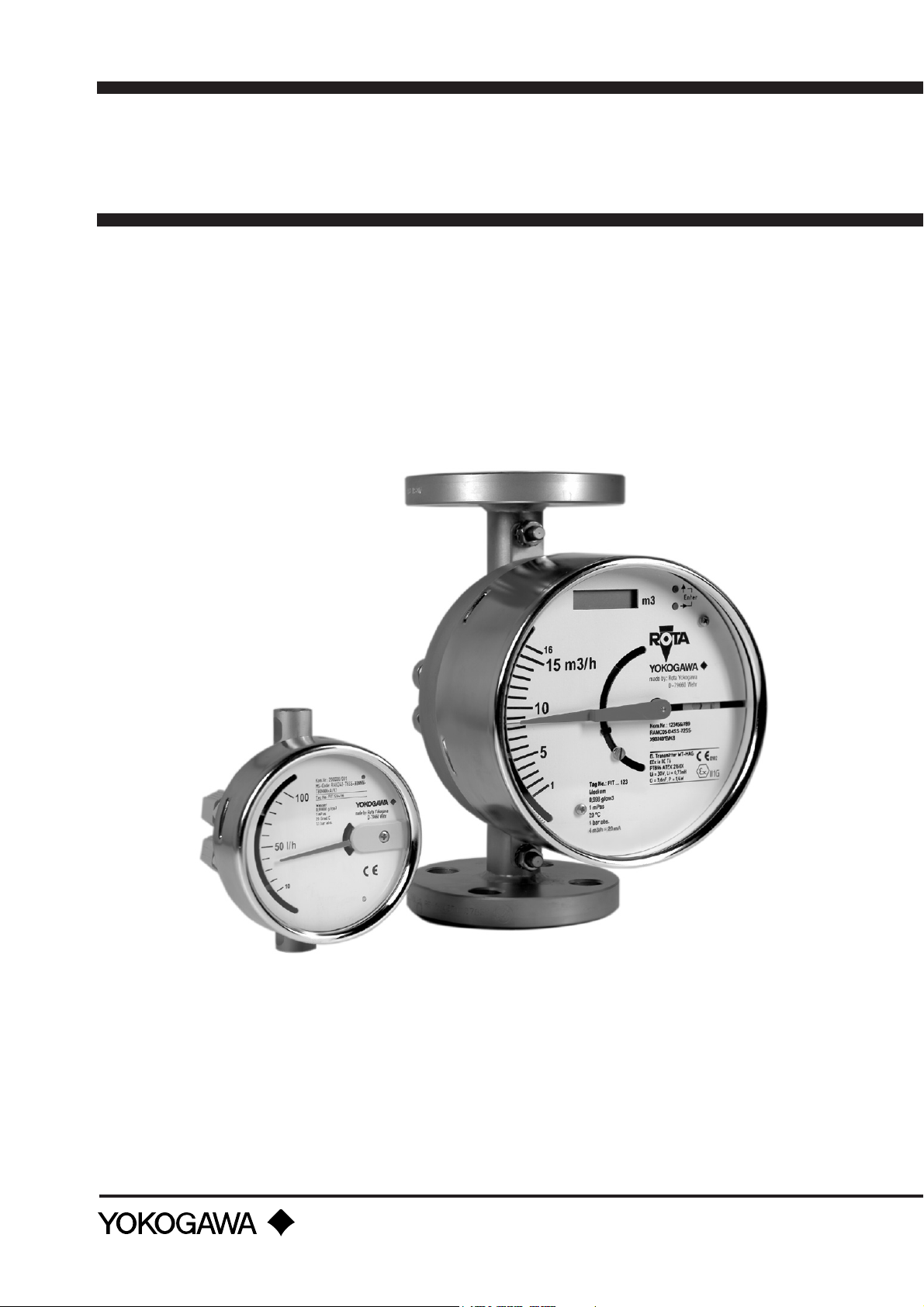
OVERVIEW ROTAMETER
Type RAMC
Metal short stroke Rotameter
Measurable flow rates
Water (20°C) min.
max.
Air (20°C) min.
(1bar absolute) max.
Tubes Tube and process
Accuracy class
acc. VDE/VDI 3513 Bl. 2
max. Process pressure 40 bar,
max. Process temperature
Standard with option /MV
Process connection Flange acc.
Materials :
Process connection 1.4404 (AISI 316L) / PTFE 1.4571 (AISI 316TI)
2.5 l/h
3
/h
130 m
0.075 m3/h
3
1400 m
connection one unit
1.6
2.5 with PTFE lining
higher on request
370 °C (with option /A2) 150°C 100°C
EN 1092-1 Form B1
or acc. ASME B 16.5
Thread neck DIN 11851
Tri clamp
Inner thread NPT; G
/h
RAKD
Mini Rotameter
0,1 l/h
250 l/h
4 l/h
8 m3/h
Tube and process
connection one unit
4 1.6
160 bar without valve
100 bar with valve
Inner thread RP
Inner thread NPT
Cutting ring thread
Nozzle ; Flange
acc. EN 1092-1 Form B1
or acc. ASME B 16.5
RAGG
Housing Rotameter
1.6 l/h
10 m3/h
25 l/h
250 m3/h
G-tube
300 mm long
depends on tube
6 - 10 bar
130°C
Flange
acc. EN 1092-1 Form B1
Inner thread Rp
Thread neck
acc. DIN 11851-SC
1.4571 (AISI 316TI) / PTFE
Fitting
Tube 1.4404 (AISI 316L) / PTFE 1.4571 (AISI 316TI) Glass (Duran 50)
Type (valve) without with valve possible
Approx. installation length
Process connections
Power supply 2/3 wire; 13.5 - 30VDC und
Output signal 0-20mA; 4-20mA 4-20mA without
Options:
Limit switch /K1 to /K10
Pulse output Only 4-wire type /CP without
Ex- type ATEX ATEX ATEX
Controller without /R1 to /R4 without
Accessories Transformer isolated barrier
Indicator housing 1.4301
(AISI 304) / Alu / PA
250 mm with flange
vertical
4 wire, 115 VAC, 230 VAC
Power supply for transmitter
Indicator housing 1.4301
(AISI 304)
(installed in head)
125 mm with inner thread
vertical or horizontal
2 wire ; 13.5 - 30 VDC without
/K1 to/K8
Transformer isolated barrier
Power supply for transmitter
Steel / Plastic
without
500 mm
vertical
/GM1; /GM2
Transformer isolated barrier
TI 1R1A0-E-H
Page 3
3
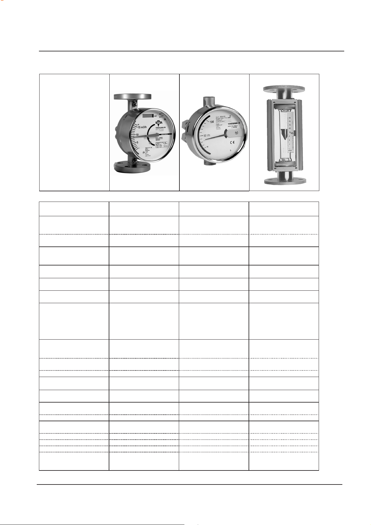
RAGH
Tube -ROTAMETER
0.002 l/h
3
/h
10 m
0.1 l/h
3
/h
210 m
L- and G-tubes
300 mm long
1.6 4 / 2.5 4; 2.5 und 1.6 depends on
depending on tube
6-16 bar
80°C
130°C
Inner thread Rp
Inner thread NPT
Nozzle
Glue socket
Flange
acc. EN 1092-1 Form B1
1.4571 (AISI 316TI) / Steel
/ PVC
1.4571 (AISI 316TI) / Steel 1.4571 (AISI 316TI)
Glass (Duran 50) Glass (Duran 50) Glass (Duran 50) Polyamid / Polysulfon
with valve possible
(installed to instrument)
310 mm - 404 mm
vertical
without
without without without without
/GM1; /GM2
without
ATEX ATEX
without /R1 to /R4 /R1 to /R4 without
Transformer isolated barrier
Bench stand (only with
hose connection)
RAGK
Mini-ROTAMETER
0.002 l/h
600 l/h
0.2 l/h
6300 l/h
K- and M-tubes
75 mm / 150 mm long
16 bar 16 bar 10 bar
100°C
130°C
Inner thread NPT
Cutting ring thread
Nozzle
Swagelok- connection
1.4571 (AISI 316TI) / Steel
/ Polypropylen
/ Polypropylen
with valve possible
(installed in head)
90 mm - 175 mm
horizontal
without without without
/GI1 to /GI4 + /GM1; /GM2 /GI1 to /GI4
without
Transformer isolated barrier
Bench stand
Panel installation
RAGL
Laboratory-
0.002 l/h
110 l/h
0.1 l/h
3500 l/h
K-, M- and L-tubes
(75, 150 und 300) mm long
tube length
100°C
130°C
Inner thread NPT
Cutting ring thread
Nozzle
Swagelok- connection
1.4571 (AISI 316TI) / Steel
/ Polypropylen / PTFE
1.4580 / Polypropylen
/ PTFE- lining
with valve possible
(installed in head)
100 mm - 325 mm
horizontal
without
ATEX
Transformer isolated barrier
Bench stand
Panel installation
ROTAMETER
RAQN
Plastic-
ROTAMETER
10 l/h
10 m3/h
3
0.16 m
/h
3
/h
250 m
Q-tubes
350 mm long
4 (2.5)
Polyamid 60°C
Polysulfon 120°C
Inner thread Rp
Glue socket
Steel / PVC
Polyamid / Polysulfon
with valve possible
(installed to instrument)
400 mm - 432 mm
vertical
/GM1; /GM2
without
ATEX
Transformer isolated barrier
TI 1R1A0-E-H
Page 4

4
α
GENERAL
Rotameters work on the principle of VA-meters and are used
to measure the flow of liquids and gases in pipes and
sheathed lines.
FEATURES
• Simple measurement principle
• Uncomplicated design
• Local indicator without additional power supply
• Low maintenance
• Suitable for continuous operation
• Cost effective
• High efficiency
• High accuracy
• Precise measurement at very low flow rates
• Replaceable floats
• Visual evaluation of measured substance possible
• Minimal pressure possible
force on the float of the
current flow of the
medium
lift
Weight of float
MEASUREMENT PRINCIPLE
A float is installed in a vertical tube whose diameter gradually
widens towards the top. The measured substance flows
vertically around the float. The float is raised according to the
flow rate, leaving a certain gap between it and the tubs wall.
Under a constant flow rate, the position of the float stabilizes.
The sum of the forces then operating on the float are zero
and the flow rate can be determined from the height of the
float.
Because of the prevailing physical relationships, the
measurement technique is dependent on the density, viscosity
and temperature of the medium. Exact results can be
expected only if the characteristics of the medium remain
constant. In the case of metal rotameters of type RAMC, the
special shape of the float results in less dependence on
viscosity at lower viscosities.
The calculation procedure for rotameters is described in VDE/
VDI3513 as a factor of medium characteristics such as
density, viscosity, pressure and temperature, and relative gas
humidity. This standard also contains useful advice on
installation conditions, maintenance, etc.
In the case of metal tubes, the height of the float is relayed by
a magnet built into the float to an external auxiliary magnet.
The latter is movable and is attached to a pointer which
translates the height of the float directly into flow rate units.
In the case of glass tubes, the flow rate at the upper edge of
the float is read on the tube scale or an attached scale
F1.EPS
Measurement principle
INFLUENCE OF TEMPERATURE ON THE FLOAT
POSITION
In Instruments with glass tubes the different coefficients of
thermal expansion between the glass tube and the float
change the position of the float at same flow rate.
Therefore the indicator must be calibrated in the following
way :
Ht)(
•∆•α−α
Ht)(
•∆•α−α
SR
∆h =
∆t = t
- tS
B
Meaning :
t
= new operating temperature
B
t
=temperature on scale or in calculation
S
∆h = change of float position
(Negative ∆h means that ∆h must be subtracted from the
indicated height of the float
accurately.)
From the flow rate tabel (Option /PT):
H = Length of scale from m
m
= smallest gap
Min
m
= largest gap
Max
= expansion coefficient of the tube
α
R
(for Duran = 3.25 x 10⁻⁶)
= expansion coefficient of the float
αSα
S
for PP = 160 x 10
SR
1m1m
+−+
1m1m
+−+
MinMax
MinMax
in order to read flow rate force
to m
Max
-6
K-1
Min
PTFE = 120 x 10-6 K-1
PVDF = 100 x 10-6 K-1
PVC = 90 x 10-6 K-1
Aluminium = 23 x 10-6 K-1
1.4571 = 16,5 x 10⁻⁶ K-1
In instruments with metal tube (RAMC and RAKD) the tube
and the float are made of the same material. Therefore no
correction is necessary.
TI 1R1A0-E-H
Page 5

5
GLASS TUBES
Additional to the local indication of flow rate glass tubes allow
a visual assessment of the process medium.
M-, L- and G- tubes have a mm-scale per default. With that
each instrument can be recalculated to different operating
conditions by the optional flow table with calculation
documents (/PT).
If an additional scale is not wanted a recalculation to different
operating conditions is not possible and in model code the
option /MM must be selected.
K-tubes have a direct scale or a 1- 10 scale and are marked
with a factor for the process medium.
The general measuring range dynamics (ratio of end to
starting value of the measurement range) is 10 : 1 for K- and
G- tubes and 20 : 1 for M- and L- tubes.
According to the installation conditions different tubes with
the following lengths and accuracy classes are used.
Glass tube Length Accuracy class acc.
K-Tube 75 mm 4 (for sphere 6)
M-Tube 150 mm 2.5 (better on request)
L-Tube 300 mm 1.6 (better on request)
G-Tube 300 mm 1.6 (better on request)
VDI/VDE 3513
T1.EPS
To avoid of electrostatic charging at gas measurement which
move the float to the tube wall the L-tubes are antistatic.
The pressure resistance of the glass tubes depends on the
diameter and determines the maximum pressure.
Tube
P
[bar]
max
K6; M6; L6;
K7; M7; L7
16
G0; G1
10
G2 G4
8 6
T2.EPS
METAL TUBES
The cone of metal RAMC tubes are forged or, with larger
sizes, mechanically turned. The process connections are
weldedfirmly attached to the tube, therefore there is no
difference between tube and housing.
Additional to the flow scale the RAMC has a mm-scale.
Therefore the scale can recalculated to different operating
conditions by the sizing software „Durep_u”
In the case of RAKD tubes, the float is cone-shaped or an
orifice is incorporated in the tube.
Model
RAMC without lining
RAMC with PTFE- lining
RAKD
Accuracy class acc.
VDI/VDE 3513
1.6 (better on request)
2.5 (better on request)
4 (better on request)
T3.EPS
FLOATS
Floats of different materials and shapes are used depending
on corrosion-resistance requirements and other installation
conditions.
Spherical floats are used for straightforward measurement of
low flow rates in liquids and gases.
Wedge-shaped floats with sloping notches are used for
greater accuracy. The notch causes the float to rotate and
thereby eliminates friction.
The number of notches varies for gases and liquids in order
to guarantee even rotation.
Low-density floats are used with gases in order to avoid
compressive oscillation. Units with valves should also be
used under these conditions or, if no valve design exists, a
valve should be installed at the inlet (or, if the input pressure
is constant, at the outlet) of the flowmeter.
Metal floats do not rotate freely in the tube but are driven.
Their special design ensures, however, that their height
matches the flow rate without hysteresis.
To aviod compressive oscillation in RAMC with gases the flaot
can be equiped with a damping (also available as retrofit kit).
SCALES
After the tubes have been calibrated, the scales are matched
to the usage conditions specified by the user.
The scale is applied directly to the tube in the case of glass
tubes, or an external scale is provided.
In the case of metal tubes, the scale is contained in a housing
which protects the magnetic follower system from
environmental influences.
Any unit which has a tube calibrated in mm can be ordered
with an Option /PT flow rate table from which flow rates can
be read and other operating conditions calculated. This design
is best suited to changing operating conditions.
The scale or flow rate table can be designed to be referenced
to a standard reference (eg, standard 0 ºC and 1.013 bars)
for volume or mass flow rate and, in the case of gases, for
volumetric flow rate.
Note
If the operating data change (density and/or viscosity), a
new scale or flow rate table must be calculated.
MAINTENANCE
Glass tubes can be checked visually to see if the float has
become dirty or damaged. If it has, the tube is demounted and
cleaned. If sign of tear is present, the tube and float should be
replaced.
Ferrometallic materials are to be avoided in the medium with
magnetic floats (instruments with limit switches or with metal
tube) because they could attach themselves to the float. If
Rotameter with metal tubes are contaminated, the instrument
should be disassembled and cleaned. If the float is damaged,
it should be replaced or the instrument should be sent to
ROTA YOKOGAWA. for servicing
TI 1R1A0-E-H
Page 6

6
S
LIMIT SWITCHES
All Rotameters with metal tube are available with limit switches.
In Rotameters with glass- or plastic-tubes special floats (with
magnet or from ferromagnetic material) must be used.
Tube
K; M; L
G; M3
RAMC
RAKD
Limit switch with inductive ring sensor
Option
GI1 – GI4
GM1; GM2
K1 – K10
K1 – K8
Principle
Inductive ring sensor
Reed contact
Inductive slot sensor
T4.EPS
F2.EPS
TECHNICHAL DATA OF OPTIONS
Limit switch : (Option /GI1 to /GI4)
(For floats of Mumetall or PVDF withFe-core only and
Qmin > 0.004 l/h water or 0.3 l/h air)
Type : Bistable inductive ringsensor
Power supply : 4.5 V to 15 V DC
Consumption : acc. DIN EN 60947-5-6 (NAMUR)
For float below ring sensor : < 1mA
above ring sensor : > 2.2 mA
Temperature range : -25°C bis +70°C not Ex-type
Protection : IP 67
Electrical connection : 2 x 0.14 mm² ,
with shield 0.4 mm², 2 m long
Power supply for limit switch : (Option: /W xx )
Each limit switch needs an own supply.
Type :Transformer isolated barrier
acc. DIN 19234 (NAMUR)
Power supply : 230V AC (/W2_)
Switching capacity : max. 250 V AC; max. 4A
Relay output : 1 or 2 potential free changeover
Explosion proof : Intrinsic safe [EEx ia] II C
Controller (Option: /R1 to R4)
(not for tube M3)
Differential pressure controller for a constant flow during
fluctuations of back pressure.
These are no pressure limiting valves.
The controller /R1 and /R2 for liquids with variable inlet or
outlet pressure and for gases with variable inlet pressure
and constant back pressure.
The controller /R3 and /R4 for gases with fluctuations of
the back pressure.
Max. liquid flow : 100 l/h
Max. gas flow : 3000 l/h
Max. pressure : 40 bar
Recommended differential pressure : > 400 mbar
Materials
Housing Membrane Springs
24V DC (/W4_)
or max. 500 VA
contacts
CrNi-Steel PTFE CrNi-Steel
Brass Buna CrNi-Steel
T5.EPS
l/h air at 20°C; 1.013 bar abs.
Limit switch : (Option /GM1 and /GM2)
(For metering tube M3 and floats with magnet only)
Type : reed contact with bistable
switching
Max. switching voltage : 230 V
Max. switching current : 0.6 A
Max. switching capacity : 12 VA or 12 W
Temperature range : -10 °C to +70 °C
Protection : IP 65
Internal capacity : 0 nF
Internal inductivity : 0 mH
Electrical connection : LIYY 2 x 0.34mm²; 1 m long
Housing : Polystyrol
Weight : 35 g
TI 1R1A0-E-H
F3.EP
Inlet pressure
Diagram controller characteristic
The curves V1 to V6 show how the flow depends on the inlet
pressure for different valve settings. The back pressure at
the outlet (ambient pressure) is 1bar.
Page 7

7
MEASURING ACCURACY
The accuracy of Rotameters are defined in VDE/VDI 3513 page 2 for different accuracy classes.
The following table gives the permissible overall error for measured values and final values in percent as a factor of the flow rate
for various accuracy classes.
Accuracy class
% overall error
% of flow rate
100
90
80
70
60
50
40
30
20 2.
10
Meas val. End val.
1
1.000 1.000
1.028 0.925
1.063 0.850
1.107 0.775
1.167 0.700
1.250 0.625
1.375 0.550
1.583 0.475
000 0.400
3.250 0.325
1.6
Meas val. End val.
1.600 1.600 2.500 2.500 4.000 4.000
1.644 1.480 2.569 2.313 4.111 3.700
1.700 1.360 2.656 2.125 4.250 3.400
1.771 1.240 2.768
1.867 1.120 2.917 1.750 4.667 2.800
2.000 1.000 3.125 1.563 5.000 2.500
2.200 0.880 3.438 1.375 5.500 2.200
2.533 0.760 3.958 1.188
3.200 0.640 5.000 1.000 8.000 1.600 12.000 2.400
5.200 0.520 8.125 0.813 13.000 1.300 19.500 1.950
2.5
Meas val. End val.
1.938
Meas val. End val.
4.429 3.100
6.333 1.900
4
Meas val. End val.
6.000 6.000
6.167 5.550
6.375 5.100
6.643 4.650
7.000 4.200
7.500
8.250 3.300
9.500 2.850
6
3.750
T6.EPS
STANDARD CALIBRATION
The calibration of standard tubes is carried out by comparing
the number of test samples with the results of other highprecision flow (master units).
The accuracy of the master tubes is better than 0.5%.
Calibration center of the GERMAN
CALIBRATION SERVICE - DKD-for the
measurement of flow rate at ROTA
YOKOGAWA,
registration number 3901
The possible values for mass flow rates and volume flow
PRECISION CALIBRATION
A weighing system is used as standard for recalibrating the
master
units and for all other calibrations where a high degree of
accuracy is required. Here, accuracies of 0.1% are achieved.
CUSTOMER SPECIFIC TUBES
rates of fluids range from 0.007 kg/min to 5000 kg/min for
iterative method and 0.33 kg/min to 15000 kg/min for comparing
counter.
The calibration center provides standards for mass, volume,
density and time tested by the Physikalisch-Technische
Bundesanstalt (PTB). The calibration center is monitored by
the PTB. Flowmeters from other manufacturers can be
calibrated at the calibration center.
Aside from the standard tubes in our units, we also offer a large number of customer-specific tubes for installation by customers in
their own housings or instrumentation.
GLASS TUBES FOR CHLORINE GAS METERING
Water for domestic use is disinfected with chlorine gas in
many parts of the world.
Glass tubes for chlorine gas 20°C; 0.95 bar abs.
Float : glass sphere
Connections : PE
Tube length : 71 mm
Outer diameter : 13 mm
Seal : rear or external
Metering range : 13 ranges from
1 – 10 g/h to 200 – 4000 g/h
PLASTIC TUBES FOR OXIGENE AND AIR METERING
In both the medical and welding professions gases are
metered manually and measured using small plastic rotameters.
Float : sphere, glass or stainless steel
Tube : PA or PS
Tube length : 115 mm
Outer diameter : 13 mm
Conditions : 20°C; 1 bar abs.
Metering range : 20 ranges 20 – 2200 l/h
GLASS TUBE FOR MEDICAL AIR, NITROUS
OXIDE AND OXYGEN METERING
Oxygen and nitrous oxide, especially, are metered for medical
purposes. The tubes have a gold rim inside and outside to
prevent static loadings.
Float : anodized aluminium
Rube length : 228.9 mm (9 inch)
Inner diameter : 11.2 mm
Outer diameter : 15.1 mm
Conditions : 20°C; 1 bar abs.
Metering range
Air : 0.2 – 15 l/min
Oxygen : 6 ranges 0.1 – 15 l/min
Nitrous oxid : 0.1 – 15 l/min
GLASS TUBES WITH METAL FLANGE
These days, small production plants are made from glass for
especially high quality products. Glass rotameters are
particularly suited for flow measurement in these cases
because no metal ions are introduced into the product.
Float : PTFE
Installation length : 350 mm
Process connection : spherical flange
Tube : Duran Glas
Metring range
Water : 0.002 l/h – 16 m3/h
Air : 0.1 l/h – 400 m3/h
Limit switch : /GM1; /GM2
TI 1R1A0-E-H
Page 8

8
TI 1R1A0-E-H
 Loading...