

Page 1
General
Specications
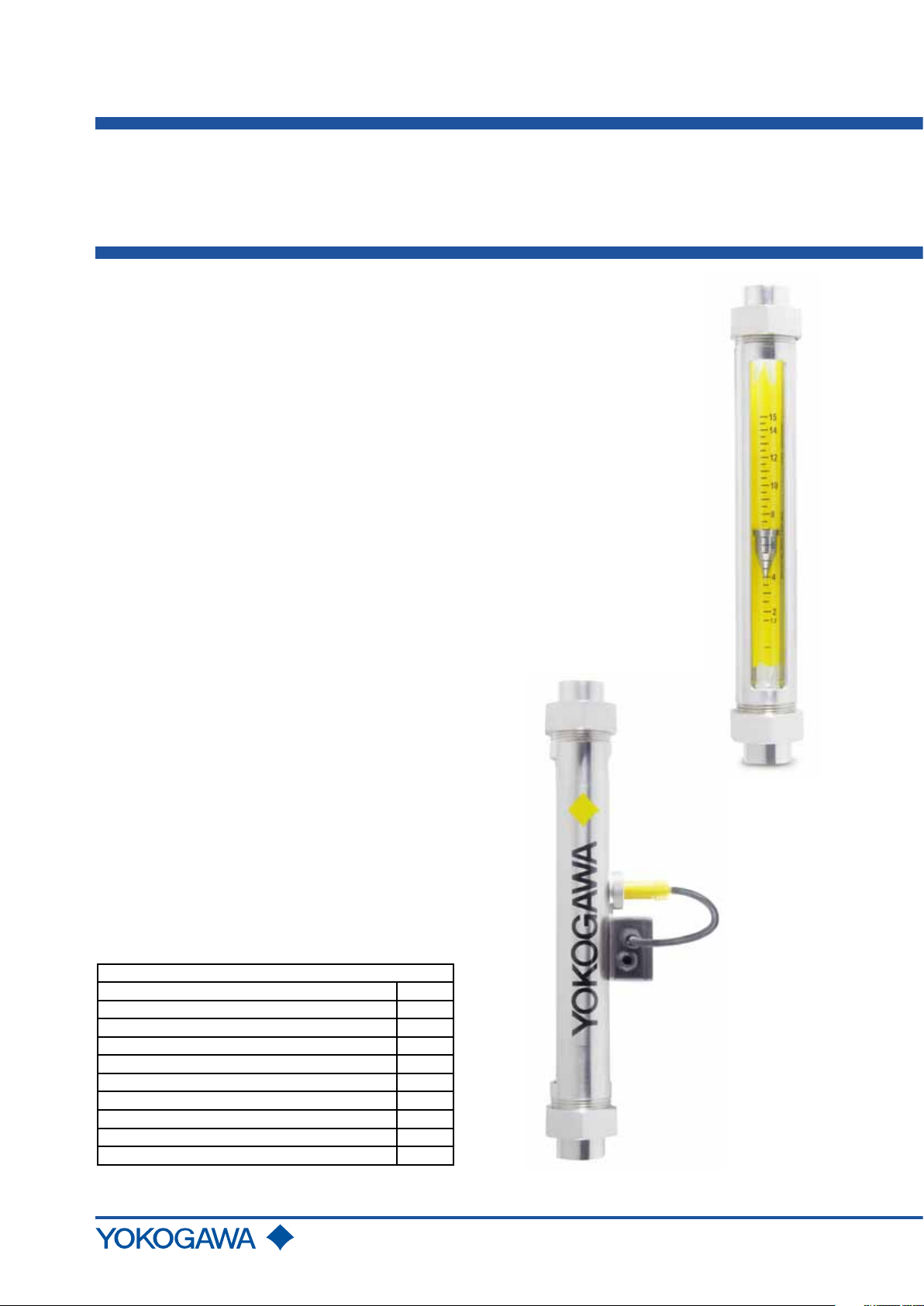
Model RAGN
Glass Rotameter
GS 01R01B10-00E-E
The Rotameter RAGN is designed for continuous ow
measurement of liquids and gases.
The uid passes through the metering tube from bottom to
top and consequently needs to be installed vertically and
ow direction is upwards. The conical glass metering tube
includes a free rotating oat which provides self stabilization.
The actual ow is indicated by the top of the oat and can
be directly read from the scale on the metering tube.
Features:
- All stainless steel design
- Turnable splinter shield
- Designed for aggressive applications
- Easy to install and maintain
- Wide measuring range selection for gases and liquids
- Low pressure loss
- Easy to read scale
- Optional limit switches with connection box
- Suitable for applications according to IEC 61508
and Machinery Directive ISO 13849
Applications:
- Visual uid monitoring
- Industrial gas measurement
- Controlling of water circuits
Contents
Features page 1
Applications page 1
Standard Specications page 2
Option Specications page 2
Model Specications page 3
Flow Table for Water / Liquids page 4
Flow Table for Air / Gases page 5
Options page 6
Procedure to select the model code page 7
Dimensions page 7
Rota Yokogawa GmbH & Co. KG
Rheinstr. 8
D-79664 Wehr
Germany
GS 01R01B10-00E-E
© Copyright 2011(Rü)
2nd edition, December 2011(Rü)
Page 2
2
STANDARD SPECIFICATIONS
Fluids to be measured : Liquids and gas
Measurable ow rates :
- Water (20 °C) : 0.002 l/h to 10 m3/h
- Air (20 °C; 1 bar abs.) : 0.1 l/h to 160 m3/h
Turndown :
- P metering tube : 10:1
- L metering tube : 20:1
Metering tubes : L6; L7; P0; P1; P2; P4 (length 300 mm)
Process temperature : -25°C to +100°C
Process pressure :
Metering tube L6;L7 P0;P1 P2 P4
Pmax (bar) 16 10 8 6
Installation length :
Process connection Thread Clamp Flange
Length [mm] 375 375 425
Weight : Depending on design (see page 7)
Accuracy :
Tube Measuring accuracy acc.
Directive VDI/VDE 3513 sheet 2 (qG= 50%)
L613 - L623 2.5%
L624 - L747 1.6%
P051 - P471 1.6%
Materials :
Threads G, NPT : AISI 316L (1.4404)
Flange EN / ASME : AISI 316L (1.4404)
Clamp ISO 2852 : AISI 316L (1.4404)
Housing : AISI 304 (1.4301)
Nut : AISI 316 (1.4401)
(or galvanized steel)
Stoppers (L6, L7 tube) : PFA
Stoppers (P0 - P4 tube) : PVDF, AISI 316L (1.4404)
Measuring cone : Borosilicate glass
Float (L6, L7 tube ) : Titanium, PVDF
Float (P0 - P4 tube) : PTFE, PVDF (FDA conform),
AISI 316Ti (1.4571)
Gaskets : NBR, FKM,EPDM (FDA conform)
Pressure Equipment Directive (PED) Directive 97/23/EG:
Models : RAGN04, RAGN05, RAGN06
Tubes :
- Modul : A
- Fluid Group : 1 (liquid, gases)
- Produced acc. to category
: I
FDA-Conformity:
RAGN with P- tube, PVDF- or SS- oat and EPDM- gaskets
(option /ME).
Stoppers and oats made of PVDF:
21 CFR § 177 2510(a)
O-rings made of EPDM:
21 CFR § 177 2600-21
Compliance with safety application acc. IEC 61508: 2010
and ISO 13849:
Please refer to the FMEDA report and instruction manual.
OPTION SPECIFICATIONS
Limit switch (option /GM1 to /GM5):
( for P- tubes with PVDF- or SS- oat with magnet only)
Type : reed contact with bistable switching
Max. switching voltage : 230 V
Max. switching current : 2 A
Max. switching capacity : 40 W/VA
Temperature range : -10°C to +70°C
Protection : IP65
Internal capacity : 0 nF
Internal inductivity : 0 mH
Electrical connection : LIYY 2 x 0.34 mm²; length 1 m
Housing : Polystyrene
Weight : 35 g
Explosion proof :
Intrinsic safe acc. EN 60079-11 chapter 5.7,
IEC 60079-11 chapter 5.7 and ANSI/ISA 60079-11
chapter 5.7 as "Simple Apparatus".
Group : IIC
Category : 2G
Temperature class : T6
Entity parameter : Ui = 15 V ; Ii = 50 mA ; Pi = 187 mW
Li ≈ 0 mH ; Ci ≈ 0 nF
Limit switch (option /GR2 to /GR8):
(for L- tubes with PVDF oat only)
Type : Bistable inductive ring sensor
Power supply : 4.5 V to 15 V DC
Consumption : acc. DIN EN 60947-5-6 (NAMUR)
Float below ring sensor : < 1 mA
Float above ring sensor : > 2.2 mA
Temperature range : -25°C to +65°C non-Ex- type
Protection : IP 67
Electrical connection : 2 x 0.14 mm² , with shield 0.4 mm²,
2 m long
Explosion proof type (option /KS1):
Temperature range : -25°C to +60°C
Marking acc. guideline 94/9/EG :
Manufacturer : Rota Yokogawa, Rheinstr.8,
D-79664 Wehr
Type : RI20-10K/G or RI20-17K/G
Year of production : in serial number
Protection : Ex ia
Group : IIC
Category : 2G
Temperature class : T6
Certicate No. : PTB 03ATEX 2111
Safety relevant data (see also certicate for data):
Ui = 12 V, Ii = 22 mA , Pi = 66 mW,
Li = 20 mH, Ci = 200 nF
CE-marking
: II 2 G
Power supply for limit switch (option /W__):
Type :
- KFD2-SH-Ex1 (24 V DC), Fail Safe, 1 channel
Power supply :
- 230 V AC ± 10%, 45-65Hz
- 115 V AC ± 10%, 45-65Hz
- 24 V DC ± 25%
Relay output :
1 or 2 potential-free changeover contact(s)
Switching capacity :
max. 250 V AC, max. 2 A
acc.
DIN EN 60947-5-6 (NAMUR)
- KFA5-SR2-Ex*-W (115 V AC),
- KFA6-SR2-Ex*-W (230 V AC),
* = 1 or 2
* = 1 or 2
- KFD2-SR2-Ex*-W (24 V DC), * = 1 or 2
- KHA6-SH-Ex1 (115/230 V AC), Fail Safe, 1 channel
GS 01R01B10-00E-E 2nd edition, December 07, 2011-00
All Rights Reserved. Copyright © 2011, Rota Yokogawa
Page 3
3
Explosion proof : Intrinsic safe [Ex ia] IIC
PTB 00 ATEX 2081 (/W1A, /W1B, /W2A, /W2B)
PTB 00 ATEX 2080 (/W4A, /W4B)
PTB 00 ATEX 2042 (/W4E, /W4F)
PTB 00 ATEX 2043 (/W2E, /W2F)
Note :
For safety application fail safe power
W2F, /W4E or /W4F must be selected in combination with
options /GR_.
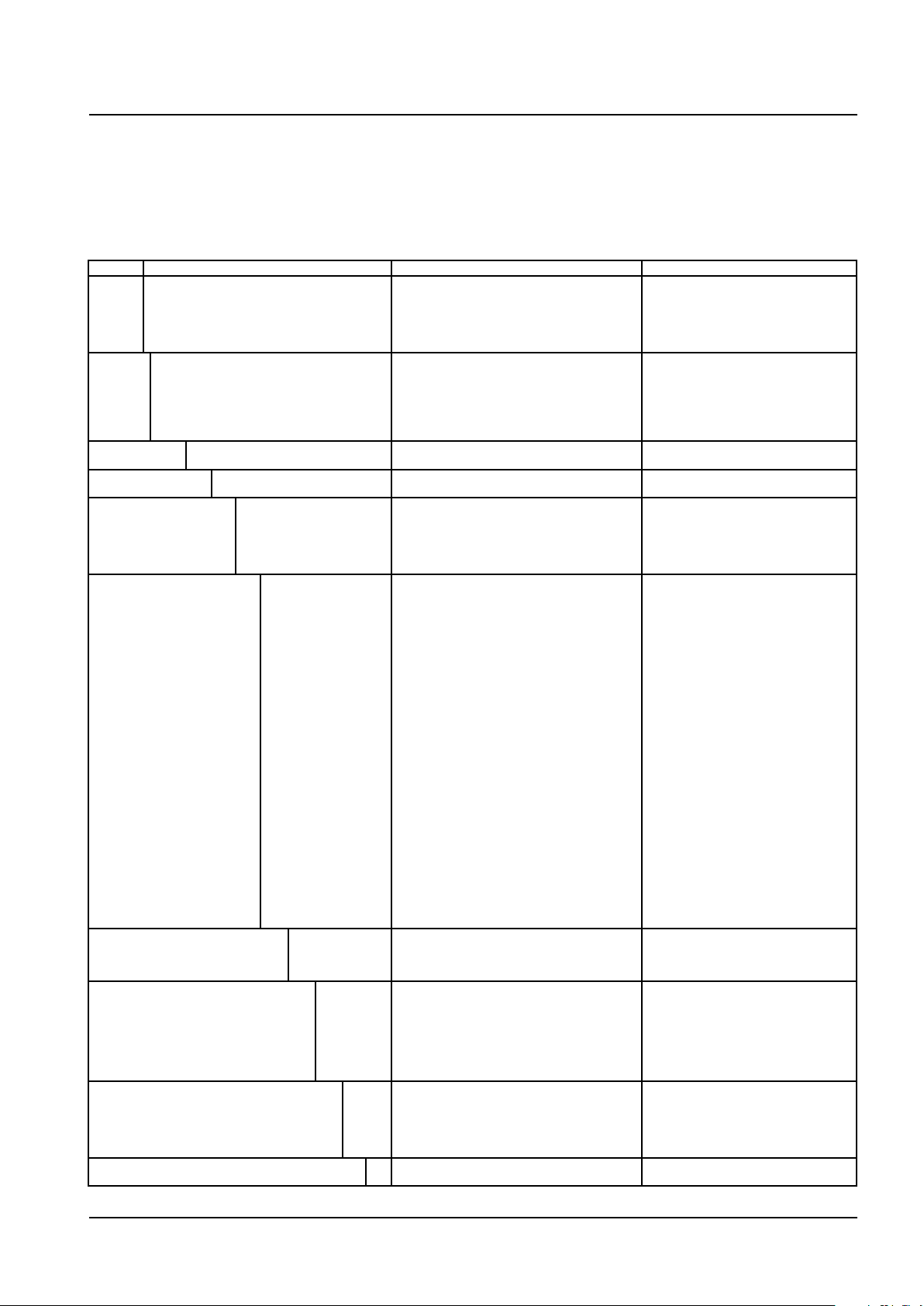
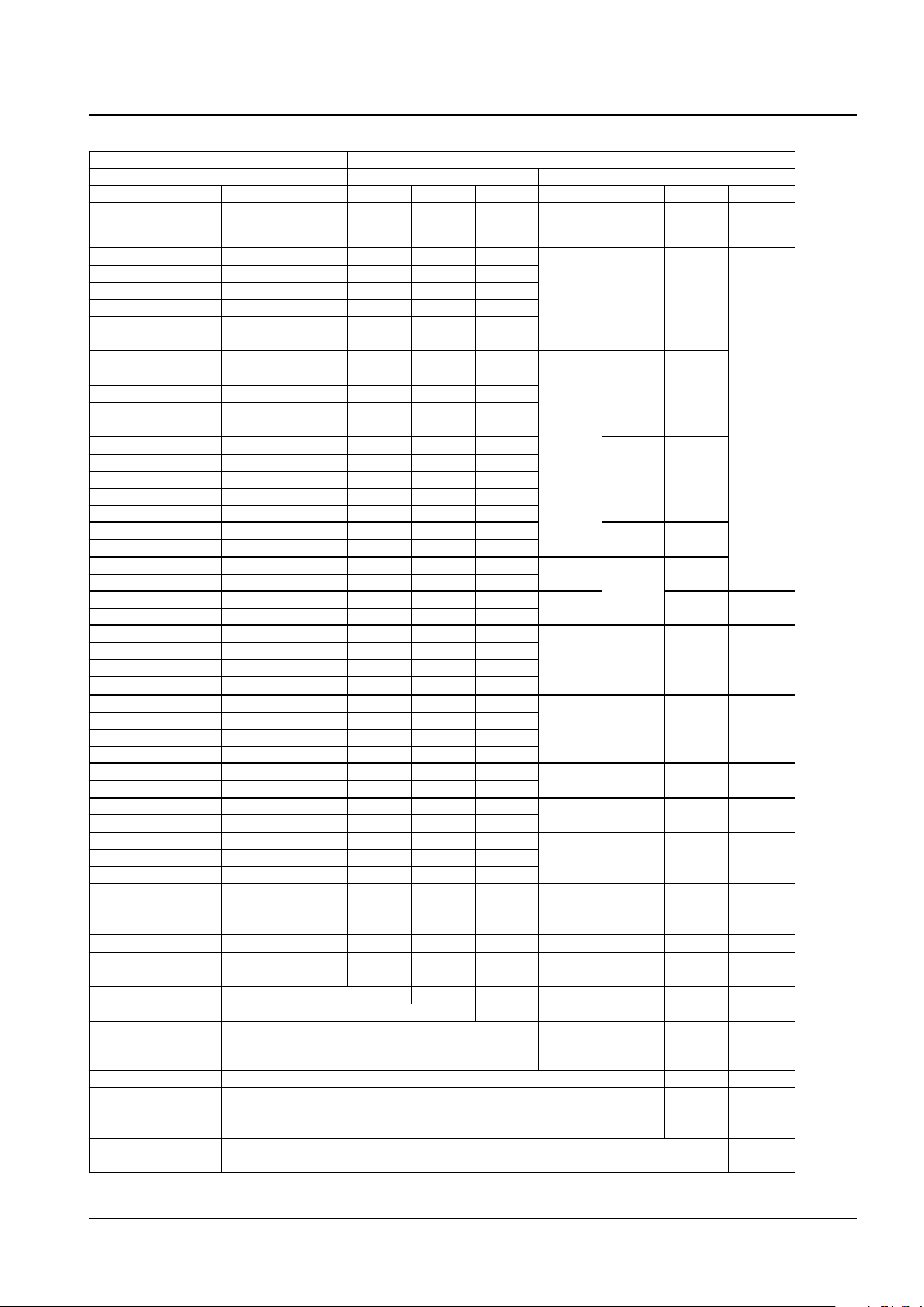
MODEL SPECIFICATIONS
Model Suffix code Description Restrictions
RAGN01
RAGN23
RAGN02
RAGN04
RAGN05
RAGN06
Process
connection
Material of process
connections
Metering tube
Diameter of metering tube 1)6
Cone
Float material
Diameter of oat
Medium / Float factor
Float insertion
1)
Combinations see tables on page 4 and 5
-D4
-A1
-G0
-T0
-S4
SS Stainless steel
1)
1)
1)
1)
-L
-P
7
0
1
2
4
1)
1)
13
14
17
21
22
23
24
27
31
32
33
34
37
41
42
43
44
47
51
52
53
54
57
61
62
63
64
67
71
-SS
-PF
-PD
-TT
A
B
C
D
0
1
2
4
L
G
2
3
6
7
Size DN 15 (½ inch)
Size DN 20 (¾ inch)
Size DN 25 (1 inch)
Size DN 40 (1½ inch)
Size DN 50 (2 inch)
Size DN 65 (2½ inch)
EN ange PN 40, process connection dimension +
facing acc. EN 1092-2 Form B1
ASME ange class 150, process connection dimension
+ facing acc. ASME B 16.5
Inner thread G
Inner thread NPT
Clamp ISO 2852
L-tube (300 mm)
P-tube (300 mm)
10 mm
17 mm
20 mm
34 mm
48 mm
81 mm
1.4571 / AISI 316 Ti
PTFE
PVDF
Titanium
1.59
3.18
6.35
9.53
12.2 (P0-oat)
21.6 (P1-oat)
31.2 (P2-oat)
54.1 (P4-oat)
For liquid
For gas
For water
For water
For air
For air
NMWithout magnet
With magnet
for D4, A1, G0, T0, S4 with L6, L7, P0, P1
for G0, T0 with L6, L7, P0, P1
for D4, A1, G0, T0, S4 with L6, L7, P0, P1, P2
for D4, A1, G0, T0 with P2, P4
for D4, A1, with P2, P4; for G0, T0 with P4
for G0, T0 with P4
supply option /W2E, /
All Rights Reserved. Copyright © 2011, Rota Yokogawa
GS 01R01B10-00E-E 2nd edition, December 07, 2011-00
Page 4
4
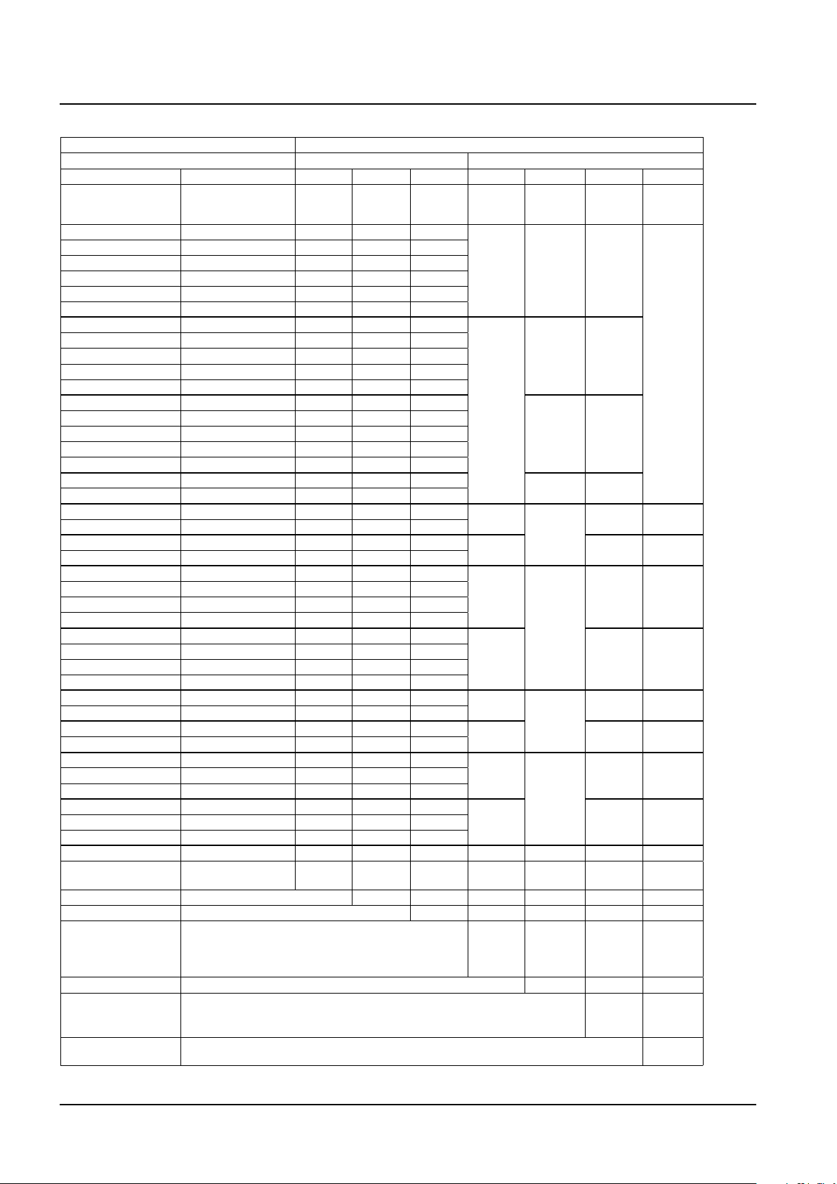
FLOW TABLE WITH METERING TUBE-FLOAT-COMBINATION FOR WATER / LIQUIDS
Flow table Suffix code metering tube - oat- combination
Water / liquids 20°C Metering tube Float
-x x xx -xx x x x
Max.
Flow
[l/h]
0.025 1 L 6 13
0.04 1 L 6 14
0.063 2 L 6 17
0.1 2 L 6 21
0.16 3 L 6 22
0.25 4 L 6 23
0.4 1 L 6 24
0.63 1 L 6 27
1 2 L 6 31
1. 6 3 L 6 32
2.5 4 L 6 33
4 2 L 7 34
6.3 2 L 7 37
10 3 L 7 41
16 4 L 7 42
25 5 L 7 43
40 5 L 7 44
63 10 L 7 47
63 10 P 0 51
100 16 P 0 52
100 16 P 0 51
160 24 P 0 52
160 15 P 1 53
250 16 P 1 54
400 18 P 1 57
630 26 P 1 61
250 15 P 1 53
400 16 P 1 54
630 18 P 1 57
1000 26 P 1 61
1000 11 P 2 62
1600 13 P 2 63
1600 26 P 2 62
2500 30 P 2 63
2500 16 P 4 64
4000 18 P 4 67
6300 21 P 4 71
4000 40 P 4 64
6300 44 P 4 67
10000 53 P 4 71
Length metering tube 300 mm .....................
Diam. metering tube 10 mm to 81 mm .......................... x
Cone metering tube See ow table .................................................. xx
Float material 1.4571 ..................................................................................
Float diameter 1.6 mm to 54 mm .................................................................................... x
Flow mark For liquid .....................................................................................................................
Float insertion Without magnet ..............................................................................................................................
1)
Max. viscosity 2 mPas*s
2)
For option limit switch /GM1 to /GM5
GS 01R01B10-00E-E 2nd edition, December 07, 2011-00
Pressure loss
Length
Diameter
Cone
Material
Diameter
Flow
mark
[mbar]
Code
Code
Code
Code
TT A
Code
Code
1)
L
B L
TT;PD
C L
D L
PD
2 M
0
SS 3
PD
2 M
1
SS 3
PD
2 M
2
SS 3
PD
2 M
4
SS 3
Description
P
300 mm .....................
L
SS
Titanium ...............................................................................
PTFE ....................................................................................
PVDF ...................................................................................
TT
PF
PD
L
For water ......................................................................................................................
For water ......................................................................................................................
2
3
With magnet ...................................................................................................................................
All Rights Reserved. Copyright © 2011, Rota Yokogawa
Insertion
Code
N
M 2);
N
M 2);
N
M 2);
N
M 2);
N
N
2)
M
Page 5
FLOW TABLE WITH METERING TUBE-FLOAT-COMBINATION FOR AIR / GASES
Flow table Suffix code metering tube - oat- combination
Air/Gases 20°C, 1 bar abs Metering tube Float
-x x xx -xx x x x
Max. Flow
[l/h]
1. 9 1 L 6 13
3 1 L 6 14
4.4 2 L 6 17
6.5 2 L 6 21
10 3 L 6 22
14 4 L 6 23
23 2 L 6 24
33 2 L 6 27
50 2 L 6 31
70 3 L 6 32
100 4 L 6 33
180 3 L 7 34
250 3 L 7 37
400 3 L 7 41
630 4 L 7 42
1000 5 L 7 43
1600 5 L 7 44
2400 10 L 7 47
1600 4 P 0 51
2500 6 P 0 52
2400 8 P 0 51
3800 11 P 0 52
6000 6 P 1 53
9300 7 P 1 54
14500 8 P 1 57
23000 10 P 1 61
400 5 P 1 53
6300 5 P 1 54
10000 6 P 1 57
16000 8 P 1 61
35000 11 P 2 62
55000 13 P 2 63
25000 8 P 2 62
40000 10 P 2 63
88000 29 P 4 64
140000 32 P 4 67
220000 34 P 4 71
63000 13 P 4 64
100000 14 P 4 67
160000 17 P 4 71
Length metering tube 300 mm .....................
Diam. metering tube 10 mm to 81 mm .......................... x
Cone metering tube See ow table .................................................. xx
Float material Titanium ...............................................................................
Float diameter 1.6 mm to 54 mm .................................................................................... x
Flow mark For gas .......................................................................................................................
Float insertion Without magnet ..............................................................................................................................
1)
For option limit switch /GM1 to /GM5
Pressure loss
Length
Diameter
Cone
Material
Diameter
Flow
mark
[mbar]
Code
Code
Code
Code
Code
Code
TT A G
B G
PD;TT
C G
D G
PF
6
0
PD 7 M
PD 1 7 M
PF 1 6 N
PD 2 7 M
PF 2 6 N
PD 4 7 M
PF 4 6 N
Description
300 mm ..................... PL
TT
PTFE ....................................................................................
PVDF ...................................................................................
PF
PD
G
For air ..........................................................................................................................
For air ..........................................................................................................................
6
7
With magnet ...................................................................................................................................
Insertion
Code
N
1)
1)
1)
1)
N
1)
M
5
All Rights Reserved. Copyright © 2011, Rota Yokogawa
GS 01R01B10-00E-E 2nd edition, December 07, 2011-00
Page 6

6
OPTIONS
Options Code Description Restriction
Marking /B1
Limit switches /GM1
Ex-proof type /KS1 ATEX intrinsically safe „ia“ Only for /GR2 to /GR8
Installation lengths
(s. also table on page 7)
Valves
(inner thread,
double tting is attached,
not for FDA)
Test and certicates /H1
Delivery to Korea /KC With KC-mark in Korea
Accessories for metering
tube
Power supply for limit
switches (transmitter
relay)
Instruction manuals /IEn
Special order /Z Special design must be specied in an extra text.
*) If no instruction manual is selected, only a Short IM and in case of limit switches a CD with instruction manuals is shipped with the owmeter.
/B4
/BG
/B10
/BD
/GM2
/GM3
/GM4
/GM5
/GR2
/GR3
/GR4
/GR6
/GR7
/GR8
/GD1
/GD2
/L12
/L13
/L14
/L15
/L16
/V1
/V2
/V3
/V4
/V5
/V6
/P2
/P3
/P6
/PP
/PT
/PM2
/PM4
/MV
/ME
/MN
/W1A
/W1B
/W2A
/W2B
/W2E
/W2F
/W4A
/W4B
/W4E
/W4F
/IDn
Tag plate (SS)
Neutral version
Customer specic notes on name plate
Percentage scale
Dual scale
Magnetic MIN-contact
Magnetic MAX-contact
Magnetic MIN-MAX-contact
Magnetic MIN-MIN-contact
Magnetic MAX-MAX-contact
Bistable inductive ring sensor
Bistable inductive ring sensor
Bistable inductive ring sensor
2 bistable inductive ring sensors
2 bistable inductive ring sensors
2 bistable inductive ring sensors
Connection box for 1 limit switch
Connection box for 2 limit switches
Installation length 500 mm
Installation length 356 mm
Installation length 368 mm
Installation length 386 mm
Installation length 394 mm
Valve made of 1.4571 G ½´´ (parts attached)
Valve made of 1.4571 G 1´´ (parts attached)
Valve made of 1.4571 G 1½´´ (parts attached)
Valve made of brass G ½´´ (parts attached)
Valve made of brass G 1´´ (parts attached)
Valve made of brass G 1½´´ (parts attached)
Oil + fat free for wetted surfaces acc. Yokogawa specication
Certicate of Compliance with the order acc. EN 10204: 2004- 2.1
As /P2 +Test report acc. to EN 10204: 2004- 2.2
Material certicate for Insertion parts or ange connections
acc. EN 10204: 2004- 3.1
Pressure test report for metering system
With ow table for recalculation + mm- scale
PAMI test (2 test points)
PAMI test (4 test points)
Gasket FKM (Viton)
Gasket EPDM (conform to FDA, -30°C to +100°C)
Nut galvanized steel
KFA5-SR2-Ex1.W / 115 V AC, 1 channel
KFA5-SR2-Ex2.W / 115 V AC, 2 channel
KFA6-SR2-Ex1.W / 230 V AC, 1 channel
KFA6-SR2-Ex2.W / 230 V AC, 2 channel
KHA6-SH-Ex1 / 115/230 V AC, 1 channel, Fail Safe
2x KHA6-SH-Ex1 / 115/230 V AC, 1 channel, Fail Safe
KFD2-SR2-Ex1.W / 24 V DC, 1 channel
KFD2-SR2-Ex2.W / 24 V DC, 2 channel
KFD2-SH-Ex1 / 24 V DC, 1 channel, Fail Safe
2x KFD2-SH-Ex1 / 24 V DC, 1 channel, Fail Safe
Quantity of instruction manuals in English
Quantity of instruction manuals in German
Plate 12 x 40 mm; max. 45 digits
Not with /KS1
Max. 45 digits
Only for tube P
Only for tube P0 to P4 and oat
insertion code M (with magnet)
Only for tube P0 to P4 and oat
insertion code M (with magnet)
Only for tube P0 to P4 and oat
insertion code M (with magnet)
Only for tube P0 to P4 and oat
insertion code M (with magnet)
Only for tube P0 to P4 and oat
insertion code M (with magnet)
Only for tube L6 with oat code PDB
Only for tube L7 with oat code PDC
Only for tube L7 with oat code PDD
Only for tube L6 with oat code PDB
Only for tube L7 with oat code PDC
Only for tube L7 with oat code PDD
Only with /GM1 to 2, /GR2 to 4
Only with /GM3 to 5, /GR6 to 8
Only for D4, A1
Only for size 01 and G0, T0
Only for size 01, 23, 02 and G0, T0
Only for size 02, 04 and G0, T0
Only for size 05, 06 and G0, T0
Only for G0 and tube L6, L7, P0
Only for G0 and tube P1
Only for G0 and tube P2
Only for G0 and tube L6, L7, P0
Only for G0 and tube P1
Only for G0 and tube P2
Only for insertion and ange
connections
Not with /V1 to /V6
Only for connections G0, T0, S4
except RAGN04-G0SS-P2 and
RAGN04-T0SS-P2
Only for connections A1, D4 and
RAGN04-G0SS-P2 and
RAGN04-T0SS-P2
conform with FDA -30°C to +100°C
not for S4 and RAGN04 with P2
n = 1 to 9 selectable *)
n = 1 to 9 selectable *)
GS 01R01B10-00E-E 2nd edition, December 07, 2011-00
All Rights Reserved. Copyright © 2011, Rota Yokogawa
Page 7
PROCEDURE TO SELECT THE MODEL CODE
1
2
4
6
8
0101
6
2
1
4
8
10
6
2
1
4
8
L
L
L
Inner thread type (T0; G0) Clamp type (S4) Flange type (D4; A1)
Please specify in the following order
- Measuring range for water/liquid or air/gas
- With or without optional limit switch
First select the required measuring range from the ow table (last column) and specify the oat insertion for the optional limit switch. Then
the suffix code for the combination metering tube - oat can be xed.
To size the Rotameter for other medium - process- conditions use sizing program Durep V.
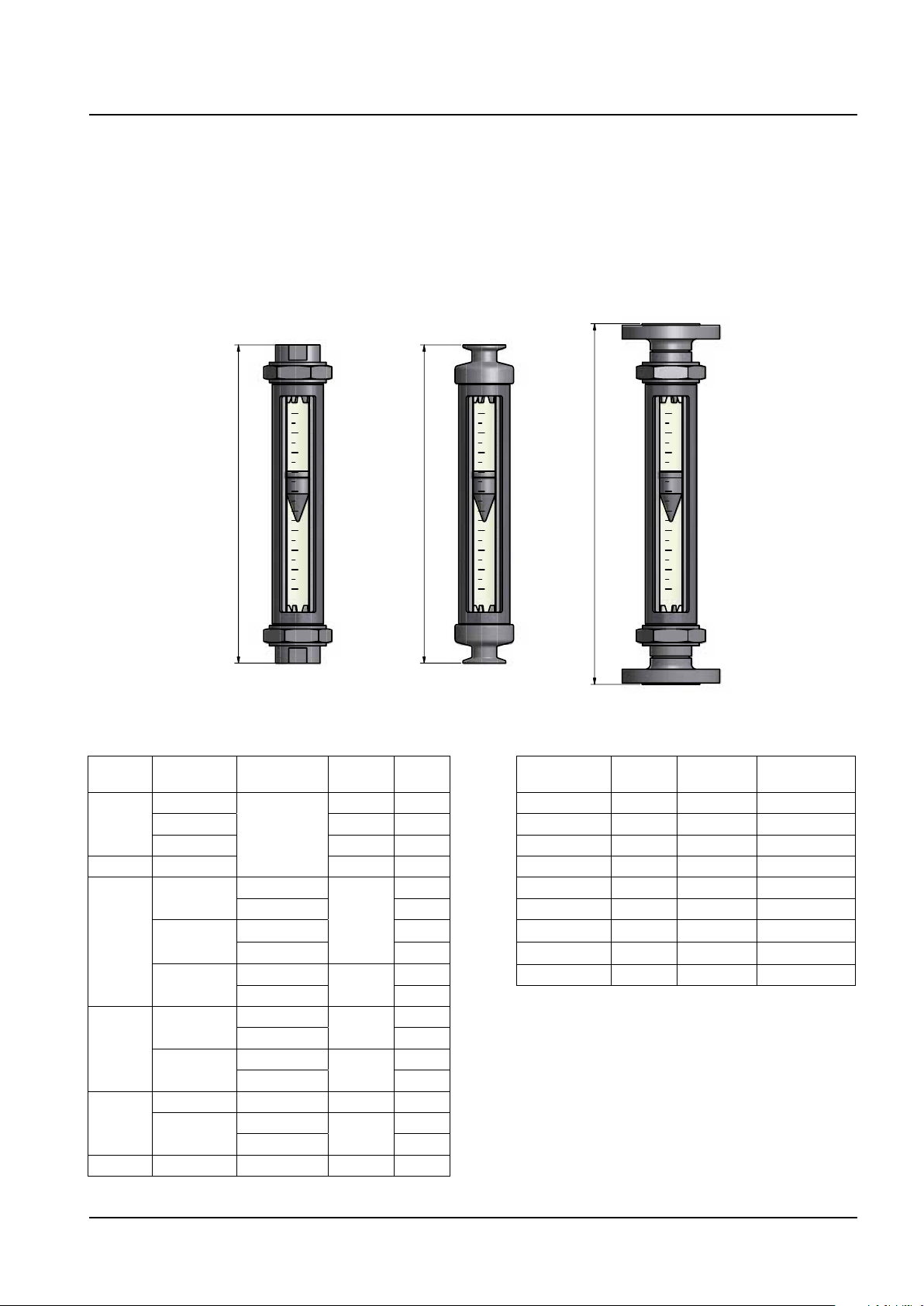
DIMENSIONS
METERING TUBE
7
Installation lengths and weights:
Model Process
RAGN01
RAGN23 Inner thread 375 1. 7
RAGN02
RAGN04
RAGN05
RAGN06 Inner thread P4 375 7. 7.1 1
connection
Inner thread
Clamp 375 1. 9
Flange 425 2.5
Inner thread
Clamp
Flange
Inner thread
Flange
Inner thread P4 375 7. 1
Flange
Tube Length LmmWeight
375 1. 7
L6; L7; P0; P1
L6; L7; P0; P1
P2 2.6
L6; L7; P0; P1 2.0
P2 2.8
L6; L7; P0; P1
P2 3.9
P2
P4 7. 1
P2
P4 8.7
P2
P4 11. 1
375
425
375
425
425
kg
1. 7
3.3
2.6
5.2
6.6
Compatibility with former Rotameter RAGG / RAGH:
Former model Tube Installation
length mm
RAGH01 L6;L7;G0 356 RAGN01..../L13
RAGH02 G1 368 RAGN02..../L14
RAGH04 G2 386 RAGN04..../L15
RAGH06 G4 394 RAGN06..../L16
RAGH23 G1 368 RAGN23..../L14
RAGH05 G4 394 RAGN05..../L16
RAGG01 G0;G1 500 RAGN01..../L12
RAGG02 G2 500 RAGN02..../L12
RAGG04 G4 500 RAGN04..../L12
Model RAGN
All Rights Reserved. Copyright © 2011, Rota Yokogawa
GS 01R01B10-00E-E 2nd edition, December 07, 2011-00
Page 8
8
Yokogawa has an extensive sales and
distribution network.
Please refer to the European website
(www.yokogawa.com/eu) to contact your
nearest representative.
Euroweg 2
3825 HD AMERSFOORT
The Netherlands
www.yokogawa.com/eu
YOKOGAWA ELECTRIC CORPORATION
World Headquarters
9-32, Nakacho 2-chome, Musashino-shi
Tokyo 180-8750
Japan
www.yokogawa.com
YOKOGAWA CORPORATION OF AMERICA
2 Dart Road
Newnan GA 30265
USA
www.yokogawa.com/us
YOKOGAWA ELECTRIC ASIA Pte. LTD.
5 Bedok South Road
Singapore 469270
Singapore
www.yokogawa.com/sg
YOKOGAWA CHINA CO. LTD.
3F Tower D Cartelo Crocodile Building
No.568 West Tianshan Road Changing District
Shanghai, China
www.yokogawa.com/cn
YOKOGAWA MIDDLE EAST B.S.C.(c)
P. O. Box 10070, Manama
Building 577, Road 2516, Busaiteen 225
Muharraq, Bahrain
www.yokogawa.com/bh
e
d
b
c
a
2
1
2
5
.5
2
6
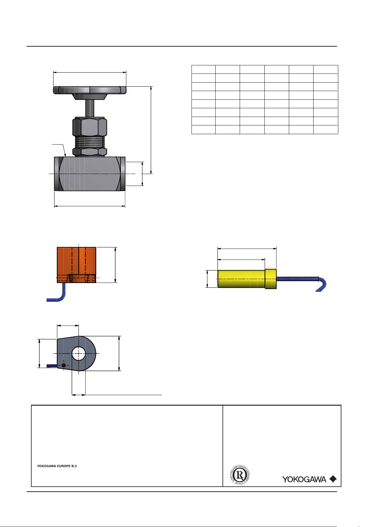
16 /GR2, /GR6
19.5 /GR3, /GR4, /GR7, /GR8
Ø 10.1 /GR2 /GR6
Ø 17.1 /GR3, /GR4, /GR7, /GR8
Ø
1
4
41
51
VALVE /Vx
Option a b c d e
Thread mm mm mm mm
/V1 G ½´´ 60 88 SW 30 63
/V2 G 1´´ 100 110 SW 45 90
/V3 G 1½´´ 130 145 SW 70 100
/V4 G ½´´ 55 78 SW 25 63
/V5 G 1´´ 75 93 SW 41 63
/V6 G 1½´´ 110 11 8 SW 60 90
LIMIT SWITCH /GRx LIMIT SWITCH /GMx
GS 01R01B10-00E-E 2nd edition, December 07, 2011-00
All Rights Reserved. Copyright © 2011, Rota Yokogawa
Subject to change without notice
 Loading...