

Page 1

User´s
Model RAGN
Manual
IM 01R01B10-00E-E
Glass ROTAMETER
Rota Yokogawa GmbH & Co. KG
Rheinstr. 8
D-79664 Wehr
Germany
IM 01R01B10-00E-E
©Copyright 2011 (Rü)
2nd edition: November 2011 (Rü)
Page 2

Blank Page
Page 3

<CONTENTS>
Contents
1. Introduction ......................................................................................... 1-1
1.1 ATEX Documentation ......................................................................................1-3
1.2 General description .........................................................................................1-4
1.3 Principle of measurement .............................................................................. 1-4
1.4 Intended use ....................................................................................................1- 4
2. Transportation and Storage ..............................................................2-1
3. Product description ...........................................................................3-1
3.1 Metering Tube ..................................................................................................3-1
3.2 Bistable inductive ring sensor (Option /GR2 to /GR8) ...............................3-2
3.3 Magnetic contact (Option /GM1 to /GM5) .....................................................3-2
i
3.4 Marking ............................................................................................................3-3
4. Installation ...........................................................................................4-1
4.1 General .............................................................................................................4-1
4.2 Piping ...............................................................................................................4-2
4.3 Bistable inductive ring sensor (Option /GR2 to /GR8) ...............................4-3
4.4 Magnetic contact (Option /GM1 to /GM5) .....................................................4-4
4.5 Connection box (Option /GD1 or /GD2) ........................................................4-5
5. Service ................................................................................................5-1
5.1 Customer maintenance part list (CMPL) ......................................................5-1
5.2 Template for sending back to service ..........................................................5-4
6. Explosion protected type instruments ............................................6-1
6.1 Bistable inductive ring sensor (Option /GR2 to /GR8) ...............................6-1
6.2 Magnetic contact (Option /GM1 to /GM5) .....................................................6-3
7. Instructions for PED ........................................................................... 7-1
8. Technical Data ....................................................................................8-1
All Rights Reserved. Copyright © 2011, Rota Yokogawa
IM 01R01B10-00E-E 2nd edition: November 01, 2011-00
Page 4

ii
<Contents>
APPENDIX 1. Safety Instrumented Systems Installation .................. A1-1
A1.1 Scope and Purpose ................................................................................... A1-1
A1.2 Using RAGN for a SIS Application ........................................................... A1-1
A1.2.1 Safety Function ................................................................................................. A1-1
A1.2.2 Diagnostic Response Time .............................................................................. A1-2
A1.2.3 Setup .................................................................................................................. A1-2
A1.2.4 Proof Testing ..................................................................................................... A1-2
A1.2.5 Repair and replacement ................................................................................... A1-2
A1.2.6 Startup Time ...................................................................................................... A1-3
A1.2.7 Reliability data ..................................................................................................A1-3
A1.2.8 Lifetime limits .................................................................................................A1-3
A1.2.9 Environmental limits ......................................................................................... A1-3
A1.2.10 Application limits ............................................................................................ A1-3
A1.3 Denitions and Abbreviations ................................................................... A1-4
A1.3.1 Denitions .........................................................................................................A1-4
A1.3.2 Abbreviations ....................................................................................................A1-4
A1.4 Assessment results .................................................................................... A1-4
A1.4.1 Safety related parameters ................................................................................ A1-4
IM 01R01B10-00E-E 2nd edition: November 01, 2011-00
All Rights Reserved. Copyright © 2011, Rota Yokogawa
Page 5
1. Introduction
WARNING
CAUTION
IMPORTANT
NOTE
WARNING
< 1. INTRODUCTION>
1-1
Before use, read this manual thoroughly and
familiarize yourself fully with the features,
operations and handling of Rotameter RAGN to
have the instrument deliver its full capabilities and
to ensure its efficient and correct use.
Notices Regarding This Manual
• This manual should be passed to the end user.
• The contents of this manual are subject to
change without prior notice.
• All rights reserved. No part of this document
may be reproduced or transmitted in any form or
by any means without the written permission of
Rota Yokogawa (hereinafter simply referred to as
Yokogawa).
• This manual neither does warrant the
marketability of this instrument nor it does
warrant that the instrument will suit a particular
purpose of the user.
• Every effort has been made to ensure accuracy
in the contents of this manual. However, should
any questions arise or errors come to your
attention, please contact your nearest Yokogawa
sales office that appears on the back of this
manual or the sales representative from which
you purchased the product.
• This manual is not intended for models with
custom specications.
• Revisions may not always be made in this
manual in conjunction with changes in
specications, constructions and/or components
if such changes are not deemed to interfere with
the instrument’s functionality or performance.
Notices Regarding Safety and Modication
• For the protection and safety of personnel, the
instrument and the system comprising the
instrument, be sure to follow the instructions on
safety described in this manual when handling
the product. If you handle the instrument in a
manner contrary to these instructions, Yokogawa
does not guarantee safety.
• If this instrument is used in a manner not
specied in this manual, the protection provided
by this instrument may be impaired.
• As for explosion proof model, if you yourself
repair or modify the instrument and then fail to
return it to its original form, the explosion
protected construction of the instrument will be
impaired, creating a hazardous condition. Be
sure to consult Yokogawa for repairs and
modications.
The following safety symbols and cautionary
notes are used on the product and in this
manual:
This symbol is used to indicate that a hazardous
condition will result which, if not avoided, may
lead to loss of life or serious injury. This manual
describes how the operator should exercise care
to avoid such a risk..
This symbol is used to indicate that a hazardous
condition will result which, if not avoided, may
lead to minor injury or material damage. This
manual describes how the operator should
exercise care to avoid a risk of bodily injury or
damage to the instrument.
This symbol is used to call your attention to a
condition that must be observed in order to avoid
the risk of damage to the instrument or system
problems.
This symbol is used to call your attention to
information that should be referred to in order to
know the operations and functions of the
instrument.
For Safe Use of Rotameter RAGN
• If the process uid is harmful to personnel,
handle Rotameter RAGN carefully even after it
has been removed from the process line
for maintenance or other purposes. Exercise
extreme care to prevent the uid from coming
into contact with human esh and to avoid
inhaling any residual gas.
• In case of Explosion proof type instrument,
further requirements and differences are
described in Chapter 6 "EXPLOSION
PROTECTED TYPE INSTRUMENTS”. The
description in Chapter 6 is prior to other
descriptions in this instruction manual.
All Rights Reserved. Copyright © 2011, Rota Yokogawa
IM 01R01B10-00E-E 2nd edition: November 01, 2011-00
Page 6
1-2
WARNING
IMPORTANT
< 1. INTRODUCTION>
Warranty
• The warranty of this instrument shall cover the
period noted on the quotation presented to the
Purchaser at the time of purchase. The Seller
shall repair the instrument free of charge when
the failure occurred during the warranty period.
• All inquiries on instrument failure should be
directed to the Seller’s sales representative from
whom you purchased the instrument or your
nearest sales office of the Seller.
• Should the instrument fail, contact the Seller
specifying the model and instrument number of
the product in question. Be specic in describing
details on the failure and the process in which
the failure occurred. It will be helpful if
schematic diagrams and/or records of data are
attached to the failed instrument.
• Whether or not the failed instrument should be
repaired free of charge shall be left solely to the
discretion of the Seller as a result of an
inspection by the Seller.
The Purchaser shall not be entitled to
receive repair services from the Seller free
of charge, even during the warranty period,
if the malfunction or damage is due to:
• improper and/or inadequate maintenance of the
instrument in question by the Purchaser.
• handling, use or storage of the instrument in
question beyond the design and/or specications
requirements.
• use of the instrument in question in a location
not conforming to the conditions specied in the
Seller’s General Specication or Instruction
Manual.
• retrotting and/or repair by an other party than
the Seller or a party to whom the Seller has
entrusted repair services.
• improper relocation of the instrument in question
after delivery.
• reason of force measure such as res,
earthquakes, storms/ oods, thunder/lightning, or
other reasons not attributable to the instrument
in question.
• YOKOGAWA gives no warranty for the improper
use of glass ow meters. Due to the uncontrollably
of the material YOKOGAWA cannot guarantee
that the material is fracture-proof.
• When removing the instrument from hazardous
processes, avoid contact with the uid and the
interior of the meter.
• In case of Explosion proof type instrument,
further requirements and differences are
described in Chapter 6 " EXPLOSION
PROTECTED TYPE INSTRUMENTS”. The
description in Chapter 6 is prior to other
descriptions in this instruction manual.
Notices regarding EMC
The Rotameter RAGN with option /GR2 ... /GR8
is conform to the European EMC Guideline and
fullls the following standards:
DIN EN 61000-4-2 : level 3
DIN EN 61000-4-3 : level 2
DIN EN 61000-4-4 : level 3
DIN EN 61000-4-6 : level 2
DIN EN 55011 : group 1 / class A
The RAGN with option /GR2 ... /GR8 is a class A
product and should be used and installed properly
according to the EMC Class A requirements.
Although the inductive ring sensor has been
designed to resist high frequency electrical
noise, if a radio transceiver is used near the
transmitter or it external wiring, the transmitter
may be affected by high frequency noise pickup.
To test for such effects, bring the transceiver in
use slowly from a distance of several meters from
the transmitter, and observe the measurement
loop for noise effects. Thereafter, always use the
transceiver outside the area affected by noise.
IM 01R01B10-00E-E 2nd edition: November 01, 2011-00
All Rights Reserved. Copyright © 2011, Rota Yokogawa
Page 7
1.1 ATEX Documentation
This is only applicable to the countries in European Union.
< 1. INTRODUCTION>
1-3
GB
DK
E
NL
SK
CZ
I
LT
LV
EST
PL
SF
P
F
D
S
SLO
H
BG
RO
M
GR
All Rights Reserved. Copyright © 2011, Rota Yokogawa
IM 01R01B10-00E-E 2nd edition: November 01, 2011-00
Page 8
1-4
FG = FF + FB = Equilibrium
R
10
20
30
40
50
60
70
80
90
100l/h
Equilibrium
F
G
F
B
F
F
< 1. INTRODUCTION>
1.2 General description
This manual describes installation, operation and maintenance of the RAGN. Please read it carefully before using
this device.
Further, please note that customer features are not described in this manual. When modifying specications,
construction or parts, this manual is not necessarily revised unless it can be assumed that these changes will
impair RAGN functions or performance.
All units are thoroughly tested before shipping. Please check the received units visually to ensure that they
have not been damaged during transport. In case of defects or questions please contact your nearest
YOKOGAWA service centre or sales office. Please describe any defect precisely and indicate model code as
well as serial number.
YOKOGAWA refuses any liability for units which have been repaired by the user without prior consent and do
not meet the specications as a consequence.
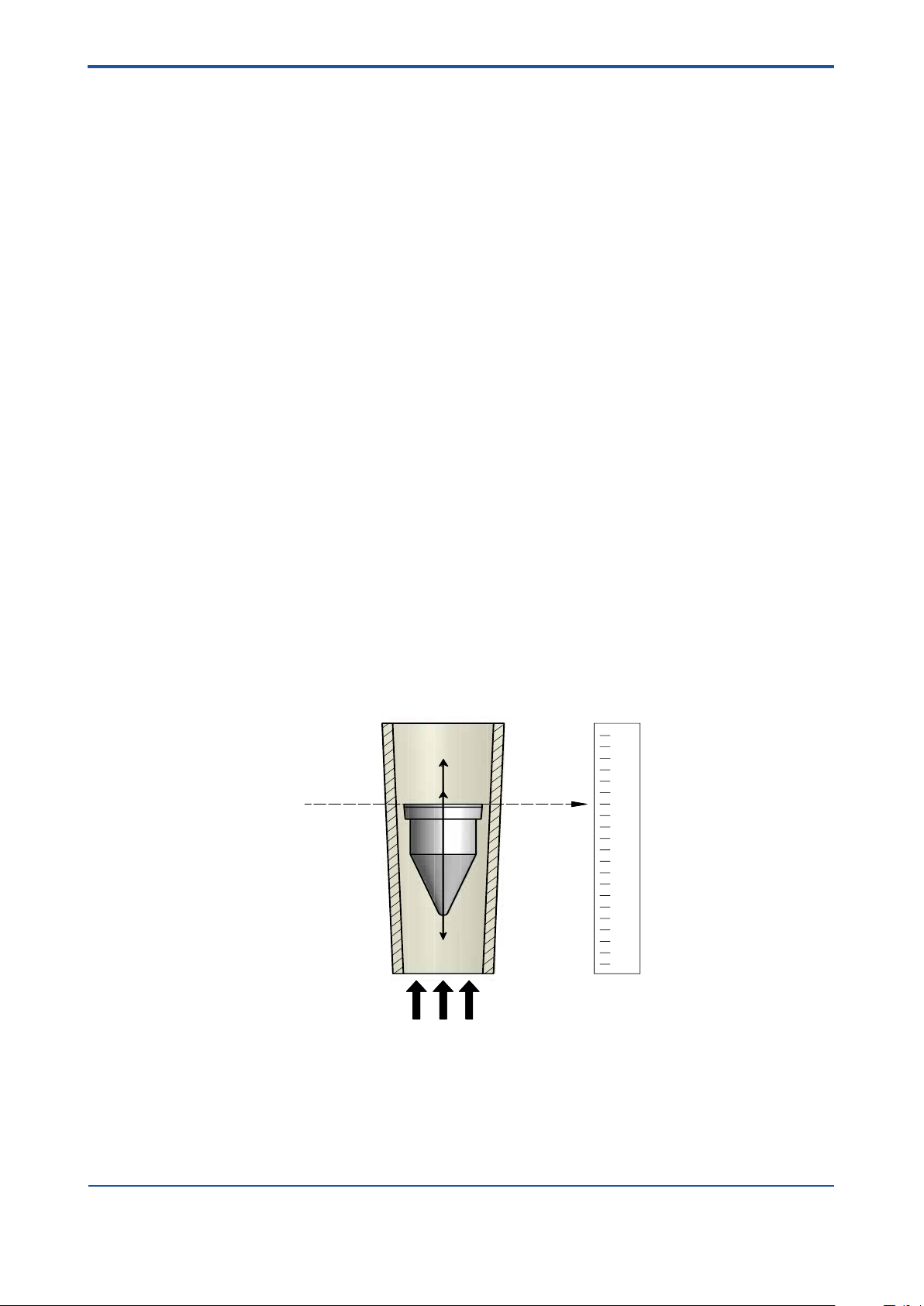
1.3 Principle of measurement
A Rotameter measures the ow of liquids, gases and steam by using a oat inside a conical tube.
The gap between the tube and oat is larger at the top to allow a greater ow to pass through the meter. As gravity
works in a vertical orientation so the tube needs to be vertically oriented.
Rota Yokogawa developed the free rotating oat which stabilises its position in the centre of the cone to provide a
more stable ow measurement.
The medium passes through the metering tube from bottom to top and consequently rises the oat until there is an
annular gap between the inside surface of the metering tube and the oat and equilibrium of the following forces
has been achieved.
Buoyancy / Gravity / Friction force
The Rotameter principle is one of the oldest and mature principles in ow measurement. This mechanical principle
is as simple as it is reliable. The ow is indicated by the top of the oat and can be read from the standard scale on
the metering tube. The RAGN can be equipped with limit switches option /GR2 to /GR8 and /GM1 to /GM5.
All units are calibrated with water or air by the manufacturer. By adjusting the calibration values to the measured
substance’s state of aggregation (density, viscosity), the ow rate scale for each measuring tube can be determined.
When the process conditions have changed the scale is not accurate any longer and the glass tube needs to be
replaced.
1.4 Intended use
The RAGN is designed for the continuous ow measurement of liquids or gases and can be used in all industries.
Typical applications are:
- Visual uid monitoring
- Industrial gas measurement
- Controlling of water circuits
IM 01R01B10-00E-E 2nd edition: November 01, 2011-00
All Rights Reserved. Copyright © 2011, Rota Yokogawa
Page 9

<2. TRANSORTATION AND STORAGE>
2-1
2. Transportation and Storage
Transportation instructions
When transporting the instrument, you must observe the following safety instructions in order to avoid lethal
injury, damage to the instrument and other material damage.
The steps involved in transport may only be carried out by qualied persons taking into account the safety
instructions.
• Observe the transport instructions on the packaging.
• Observe the below mentioned storage conditions.
• Use only the original packaging.
• The packaging material must be disposed of in accordance with the regulations.
• The transport braces must not be removed until installation.
• Read the chapter “Safety instructions”.
• To avoid any damages, unpack the ow meter only at the installation site.
• Mechanical shocks are to be avoided.
Storage conditions
Please note the following for storage purposes :
• The instrument should be stored in its transport packaging.
• Choose a storage place that meets the following requirements:
• Protection from rain and humidity
• Free of mechanical vibration and shocks
• Ambient temperature between -25°C to 60°C
• Atmospheric humidity ranging from 0 to 100%. Operation above 95% for longer times is not recommended
Before storing a used ow meter remove any uid from the ow meter and clean it in order to avoid fouling.
Properties of the instrument can change when stored outdoors.
All Rights Reserved. Copyright © 2011, Rota Yokogawa
IM 01R01B10-00E-E 2nd edition: November 01, 2011-00
Page 10

2-2
<2. TRANPORTATION AND STORAGE>
Blank Page
IM 01R01B10-00E-E 2nd edition: November 01, 2011-00
All Rights Reserved. Copyright © 2011, Rota Yokogawa
Page 11
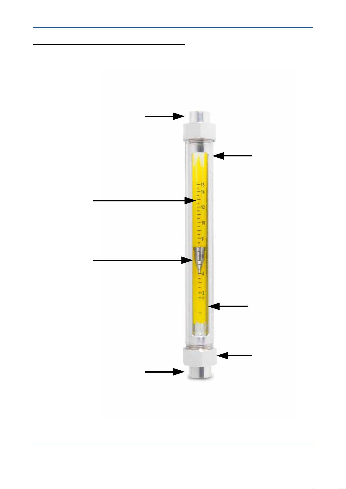
3. Product description
Process connection
Process connection
Float
Scale on tube
Nuts
Tubular frame
Splinter shield
3.1 Metering Tube
<3. PRODUCT DESCRIPTION>
3-1
All Rights Reserved. Copyright © 2011, Rota Yokogawa
IM 01R01B10-00E-E 2nd edition: November 01, 2011-00
Page 12

3-2
<3. PRODUCT DESCRIPTION>
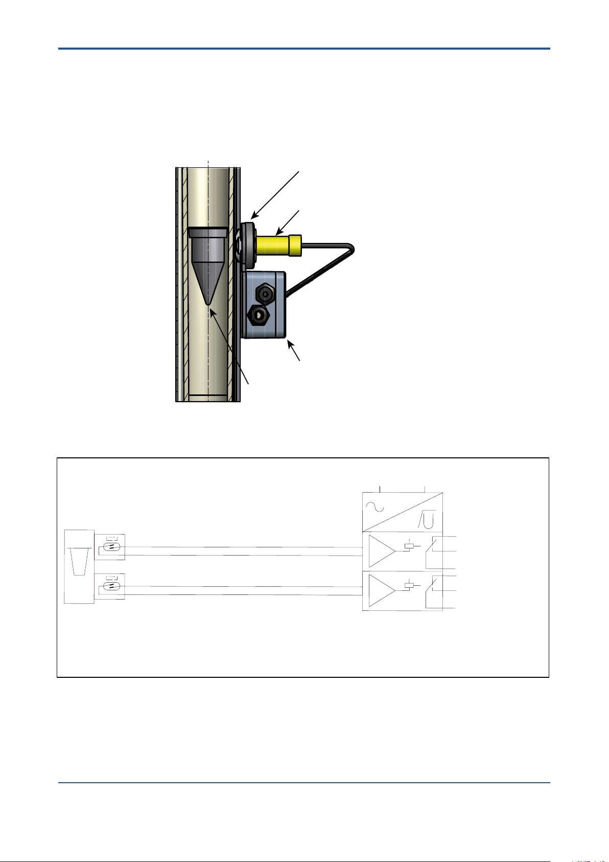
3.2 Bistable inductive ring sensor (Option /GR2 to /GR8)
The ring sensor type RI20 is intended for connection to glass Rotameters. It indicates whether the oat is
positioned above or below the sensor.
The oat must have ferromagnetic properties (e.g. a PVDF oat with iron core).
The device is offered into 3 versions:
Type Option Diameter of tube Possible oat (Yokogawa Code)
RI20-10 G /GR2, /GR6 10mm -PD B_N
RI20-17 K /GR3, /GR7 17mm -PD C_N
RI20-17 G /GR4, /GR8 17mm -PD D_N
The RI20 is bistable, i.e. if the oat is below the switch point, current consumption is always < 1 mA and it is
> 2.2 mA, if the oat is above the switch point. After power on or after power fail the RI20 shows
I < 1 mA. To nd the correct oat position the oat has to move once through the RI20.
It is intended for connection to a non-bistable isolation-switch amplier complying with DIN EN 50227
(NAMUR) (e.g. options /Wxx). With its plastic housing and its sealed-in electronic equipment, the RI20
meets the requirements for protection class IP67 and can also be operated safely in aggressive
atmospheres.
The RI20 is maintenance-free.
See chapter 6 "EXPLOSION PROTECTED TYPE INSTRUMENTS” for devices in ATEX version.
3.3 Magnetic contact (Option /GM1 to /GM5)
The limit switch is mounted to a Rotameter type RAGN, if a magnetic oat is used and indicates if the ow
falls below the set limit (MIN-contact) or exceeds the set limit (MAX-contact).
When reaching the switch point the Reed contact with bias by a permanent magnet opens when the oat
enters the alarm range. The Reed contact closes when the oat leaves the alarm range. Opened or closed
the Reed contact remains because of its bistability in its position no matter how far the oat moves away.
Due to the low switch output of the Reed contact (max, 10 VA/(W), max. 0.5 A, max. 230 V AC) a
transformer isolated barrier (e.g. option /Wxx) should be connected to the GM.
IM 01R01B10-00E-E 2nd edition: November 01, 2011-00
All Rights Reserved. Copyright © 2011, Rota Yokogawa
Page 13
3.4 Marking
Rota Yokogaw
Rheinstr. 8
D-79664 Wehr
Type : RI20-10-K
U = 4.5 ... 15V
SN : ..............
ROTA YOKOGAWA D-79664 Wehr
S/N D1L301985
RAGN01-D4SS-L624-TTBLN/B1/B4/L12/V1/GM1/GD/MN/P6/H1
PS:16bar TS:-25°C-100°C PTmax:24bar
100% = 650 l/min Wasser 20°C
Tag-No:123456789012345678901234567890123456789012345
KCC-REMRYG-GR-RAGN
*)
**)
*) only for RAGN04, RAGN05, RAGN06 **) only with option /KC
Name plate of RAGN:
Name plate of inductive ring sensor (option /GR2 to /GR8)
<3. PRODUCT DESCRIPTION>
3-3
Rota Yokogawa
Rota Yokogaw
Rheinstr. 8
Rheinstr. 8
D-79664 Wehr
D-79664 Wehr
Type : RI20-10-K
Type : RI20-10-K
U = 4.5 ... 15V
U = 4.5 ... 15V
SN : ..............
SN : ..............
All Rights Reserved. Copyright © 2011, Rota Yokogawa
IM 01R01B10-00E-E 2nd edition: November 01, 2011-00
Page 14

3-4
<3. PRODUCT DESCRIPTION>
Blank Page
IM 01R01B10-00E-E 2nd edition: November 01, 2011-00
All Rights Reserved. Copyright © 2011, Rota Yokogawa
Page 15

<4. INSTALLATION>
4-1
4. Installation
4.1 General
Installation:
All packaging material must be removed. The transportation lock for the oat must be removed.
The piping shall be ushed before installing the owmeter. Piping must be dried for gas applications. Rotameters must be installed vertically. The ow direction is from bottom to top. Prevent the device from mechani-
cal stress and vibration by aligning and supporting the piping. Avoid large volumes of gas downstream and
upstream of the device, this can cause vibration due to compression. Install the On/Off valve downstream in order
to avoid
damage when opening the valve. In case of gas applications, increase the ow pressure slowly. Avoid pressure
surges and temperature shocks to the owmeter at any time.
Refer to the pressure and temperature limits of the device. For owmeters with limit switches please see
chapter 4.3, 4.4 and 4.5.
Further installation hints can be found in VDI/VDE 3513 sheet 3.
Commissioning:
When functioning properly, the oat moves freely in the ow. With oats with notches this can be easily seen
by their rotation. If the oat does not move, please check the installation.
The ow rate can be read directly from the scale on the tube. Refer to the scale mark to which the oat adjusts
its top edge when reading.
Maintenance:
With common applications and normal operating conditions the device is maintenance free. In case of soiling
we recommend to clean the measuring tube by using a bottle brush and soap water. Make sure not to scratch
the measuring tube. If oat or measuring tube show signs of wear and tear, we recommend replacing them.
All Rights Reserved. Copyright © 2011, Rota Yokogawa
IM 01R01B10-00E-E 2nd edition: November 01, 2011-00
Page 16
4-2
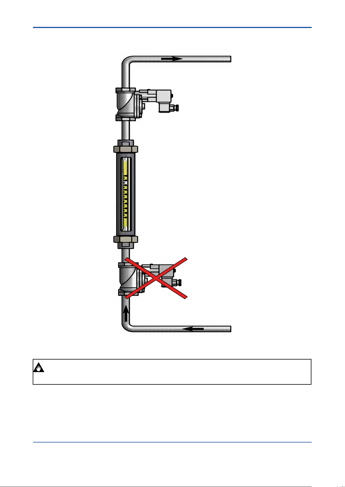
IMPORTANT
4.2 Piping
<4. INSTALLATION
On/Off- valve must be installed downstream !
IM 01R01B10-00E-E 2nd edition: November 01, 2011-00
All Rights Reserved. Copyright © 2011, Rota Yokogawa
Page 17
<4. INSTALLATION>
15
4
6
3
1
14
12
10
11
8
7
9
U
Mains / Netz / Tension
One channel transmitter : ...-SR2-Ex1. W, connection like limit MAX
Einkanaliger Verstärker : ...-SR2-Ex1. W, Anschluss wie Grenzwert MAX
Un canal amplificateur : ...-SR2-Ex1. W, raccord comme limite MAX
Transmitter Relay
Trennschaltverstärker
Amplificateur Separateur
Limit / Grenzwert / Limite MIN
Limit / Grenzwert / Limite MAX
Max
Min
EN 60947-5-6 (Namur)
-
+
-
+
~ ~
+
-
+
-
Option /W4B 24VDC
KFD2-SR2-Ex2.W
Option /W2B 230VAC
KFA6-SR2-Ex2.W
Inductive ring sensor
Induktiver Ringinitiator
Bague inductive
Rotameter RAGN option /GRx (x = 2 ... 8)
F41.EPS
min. 6 mmmin. 4 mm min. 25 mm
4-3
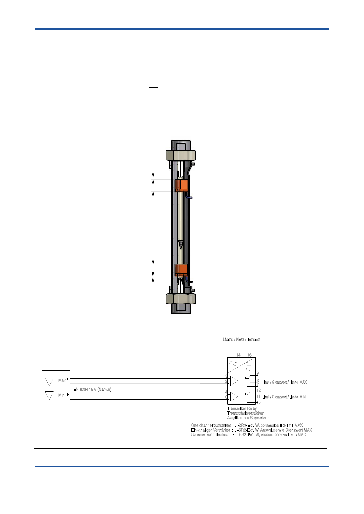
4.3 Bistable inductive ring sensor (Option /GR2 to /GR8)
- The ring sensor should be connected to a mono stable transmitter relay.
- Connection to transmitter relay (s. installation diagram below)
white cable → +
shielding → –
- The installation regulations in accordance with IEC 364 have to be taken into account.
- The shielding of the connection cable is not for earthing of the ring sensor. A ring sensor with a damaged
cable insulation may not be used
- The device has to be protected from strong electromagnetic elds.
- Power lines have to be installed separated from the signal lines.
- Switches, power relays and engines can change the switching state of the ring sensor (in unfavorable orders).
- Metal parts should have a minimum distance of 50 mm to the ring sensor.
- If the oat is above the ring sensor after power on or after power fail, the oat has to move once through
the ring sensor to nd the correct oat position.
Connection to transmitter relay :
For installation in hazardous area see chapter 6 "EXPLOSION PROTECTED TYPE INSTRUMENTS”.
All Rights Reserved. Copyright © 2011, Rota Yokogawa
IM 01R01B10-00E-E 2nd edition: November 01, 2011-00
Page 18
4-4
Optional connection box /GD1
Limit switch /GM1 or /GM2
Float with magnet
Nut
F45.EPS
GRENZWERTSCHALTER GM
LIMIT SWITCH GM
CONTACT LIMITE GM
ROTAMETER RAGN with option /GMx (x = 1 ... 5)
EN 60947-5-6 (NAMUR)
MAINS / NETZ / TENSION
OPTION: /W4B 24VDC
KFD2-SR2-Ex.W
OPTION: /W2B 230VAC
KFA6-SR2-Ex.W
9
8
1
1
1
7
1 1
1
3
4
6
+
-
+
-
LIMIT/ GRENZWERT/ LIMITE
MAX
MIN
ÄTRENNSCHALTVERST RKER
TRANSFORMER ISOLATED BARRIER
AMPLIFICATEUR SEPARATEUR
(L+ (L-)
EINKANALIGE VERSTÄRKER .......-SR2-EX1.W ANSCHLUSS WIE GRENZWERT "MAX"
ONE CHANNEL TRANSMITTER .....-SR2-EX1.W CONNECTION LIKE LIMIT "MAX"
UN CANAL AMPLIFICATEUR ........-SR2-EX1.W RACCORD COMME LIMITE "MAX"
LIMIT/ GRENZWERT/ LIMITE
<4. INSTALLATION
4.4 Magnetic contact (Option /GM1 to /GM5)
a) Loose the nut at the guide sleeve.
b) If 2 limit switches were ordered install the Max-contact in the top position and the Min- contact
in the low position (see print on housing).
c) Put the limit switch from the outer side on the guide rail of the Rotameter.
d) Adjust the distance between limit switch to tube to 1 mm; check function and correct if necessary.
e) Fix limit switch with the nut to guide rail.
Connection to transmitter relay :
IM 01R01B10-00E-E 2nd edition: November 01, 2011-00
All Rights Reserved. Copyright © 2011, Rota Yokogawa
Page 19
<4. INSTALLATION>
Option /GD1
4-5
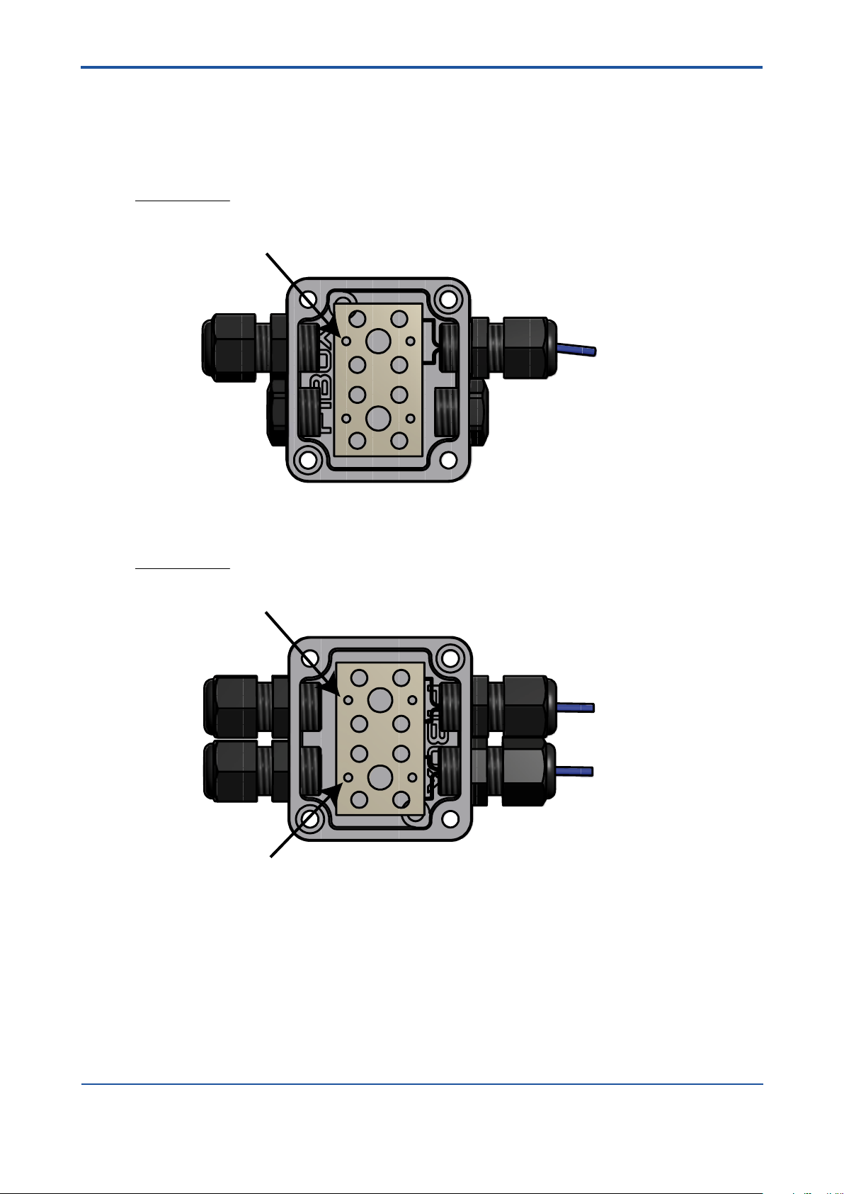
4.5 Connection box (Option /GD1 or /GD2)
For one limit switch the connection box with option /GD1 and for two limit switches the connection box with
option /GD2 is available.
Please make the connections in the connection box as shown below.
Te rminals for limit switch control unit,
e.g. transmitter relay option /Wxx
from limit switch
/GRx or /GMx
Option /GD2
Te rminals for limit switch control unit, e.g. transmitter relay option /Wxx
from limit switch
/GRx or /GMx
from limit switch
/GRx or /GMx
Te rminals for limit switch control unit, e.g. transmitter relay option /Wxx
All Rights Reserved. Copyright © 2011, Rota Yokogawa
IM 01R01B10-00E-E 2nd edition: November 01, 2011-00
Page 20

4-6
<4. INSTALLATION
Blank Page
IM 01R01B10-00E-E 2nd edition: November 01, 2011-00
All Rights Reserved. Copyright © 2011, Rota Yokogawa
Page 21
<5. SERVICE>
5. Service
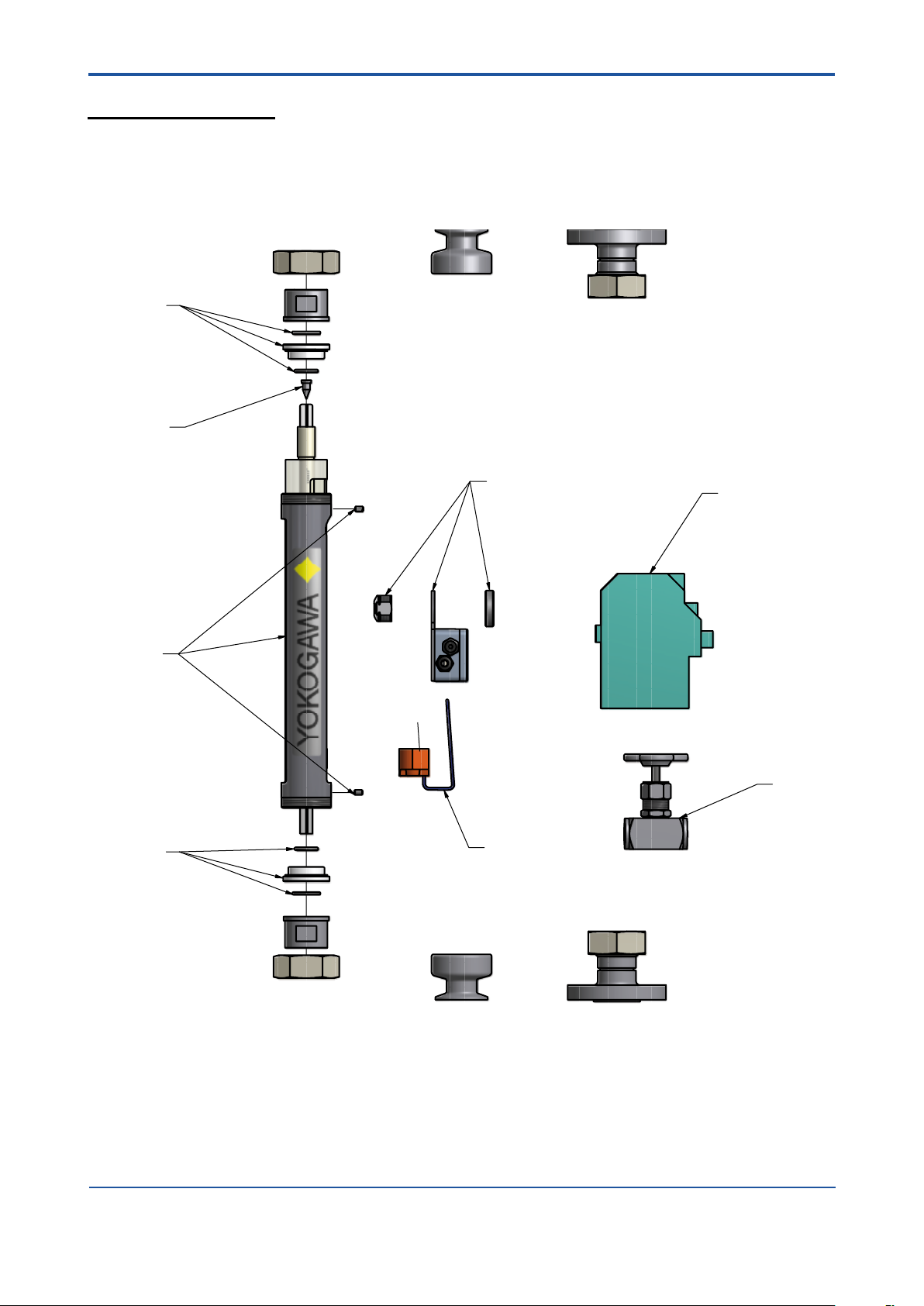
5.1 Customer maintenance part list (CMPL)
L- TUBE :
1
2
5-1
4
3
1
5
7
8
All Rights Reserved. Copyright © 2011, Rota Yokogawa
IM 01R01B10-00E-E 2nd edition: November 01, 2011-00
Page 22
5-2
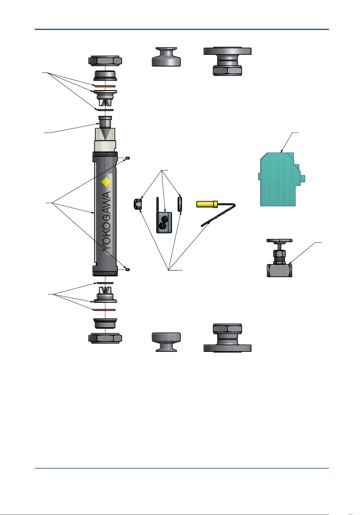
P- TUBE :
1
<5. SERVICE>
2
7
4
3
8
6
1
IM 01R01B10-00E-E 2nd edition: November 01, 2011-00
All Rights Reserved. Copyright © 2011, Rota Yokogawa
Page 23

<5. SERVICE>
Item Part-No. Descriptions
L6 tube
M3810TA-SP Set of bottom and top stoppers and Buna, Viton, EPDM gaskets for L6 tube x
M3810TB-SP Set of bottom and top stoppers and Buna, Viton, EPDM gaskets for L7 tube x
M3810TC-SP Set of bottom and top stoppers and Buna, Viton, EPDM gaskets for P0 tube x
1
M3810TD-SP Set of bottom and top stoppers and Buna, Viton, EPDM gaskets for P1 tube x
M3810TE-SP Set of bottom and top stoppers and Buna, Viton, EPDM gaskets for P2 tube x
M3810TF-SP Set of bottom and top stoppers and Buna, Viton, EPDM gaskets for P4 tube x
M3810TK-SP Spare oat PD12M x
M3809MK-SP Spare oat PD17M x
M3810TL-SP Spare oat SS13N x
M3810TM-SP Spare oat SS13M x
M3810TN-SP Spare oat PF16N x
M3809MC-SP Spare oat PD22M x
M3809ME-SP Spare oat PD27M x
2
M3810TP-SP Spare oat SS23N x
M3810TQ-SP Spare oat SS23M x
M3810TR-SP Spare oat PF26N x
M3809MD-SP Spare oat PD42M x
M3809MF-SP Spare oat PD47M x
M3810TS-SP Spare oat SS43N x
M3810TT-SP Spare oat SS43M x
M3810TW-SP Spare oat PF46N x
M3810TG-SP Splinter shield incl. 2 slotted set screws with at point for tube L6,L7,P0,P1 x x x x
3
M3810TH-SP Splinter shield incl. 2 slotted set screws with at point for tube P2 x
M3810TJ-SP Splinter shield incl. 2 slotted set screws with at point for tube P4 x
M3810GM-SP Connection box for 1 limit switch x x x x x x
4
M3810GN-SP Connection box for 2 limit switches x x x x x x
M3810TX-SP Bistable inductive ring sensor for oat PDB__ (/GR2 or /GR6)) x
5
M3810TY-SP Bistable inductive ring sensor for oat PDC__ (/GR3 or /GR7) x
M3810TZ-SP Bistable inductive ring sensor for oat PDD__ (/GR4 or /GR8) x
M3810GD-SP Magnetic MIN-contact for oat with insertion code ____M (/GM1) x x x x
M3810GE-SP Magnetic MAX-contact for oat with insertion code ____M (/GM2) x x x x
6
M3810GF-SP Magnetic MIN-MAX-contact for oat with insertion code ____M (/GM3) x x x x
M3810GG-SP Magnetic MIN-MIN-contact for oat with insertion code ____M (/GM4) x x x x
M3810GH-SP Magnetic MAX-MAX-contact for oat with insertion code ____M (/GM5) x x x x
M3810WA-SP Transmitter relay KFA5-SR2-Ex1.W / 115 V AC, 1 channel (/W1A) x x x x x x
M3810WB-SP Transmitter relay KFA5-SR2-Ex2.W / 115 V AC, 2 channel (/W1B) x x x x x x
M3810WC-SP Transmitter relay KFA6-SR2-Ex1.W / 230 V AC, 1 channel (/W2A) x x x x x x
7
M3810WD-SP Transmitter relay KFA6-SR2-Ex2.W / 230 V AC, 2 channel (/W2B) x x x x x x
M3810WE-SP Transmitter relay KFD2-SR2-Ex1.W / 24 V DC, 1 channel (/W4A) x x x x x x
M3810WF-SP Transmitter relay KFD2-SR2-Ex2.W / 24 V DC, 2 channel (/W4B) x x x x x x
M3810EQ-SP Valve made of SS 316Ti (1.4571) G 1/2" (/V1) x x x
M3810ER-SP Valve made of SS 316Ti (1.4571) G 1" (/V2) x
M3810ES-SP Valve made of SS 316Ti (1.4571) G 1 1/2" (/V3) x
8
M3810ET-SP Valve made of brass G 1/2" (/V4) x x x
M3810EW-SP Valve made of brass G 1" (/V5) x
M3810EX-SP Valve made of brass G 1 1/2" (/V6) x
IM 01R01B10-00D-E Printed Instruction Manual in German x x x x x x
9
IM 01R01B10-00E-E Printed Instruction Manual in English x x x x x x
L7 tube
P0 tube
5-3
P1 tube
P2 tube
P4 tube
All Rights Reserved. Copyright © 2011, Rota Yokogawa
IM 01R01B10-00E-E 2nd edition: November 01, 2011-00
Page 24

5-4
<5. SERVICE>
5.2 Template for sending back to service
Sending an instrument back to service
Installation and operation of the Rotameter RAGN in compliance with this manual is generally trouble-free.
In case a RAGN has to be sent for repairs or checking to our service, please observe the following:
Due to legislation for the protection of the environment and for the safety of our staff, YOKOGAWA may only
ship, repair and check sent devices on the condition that this does not constitute any risk to environment
and staff.
YOKOGAWA can only process your returned RAGN if you attach a certicate of harmlessness according to
the following sample.
If the unit has been in contact with corrosive, poisonous, ammable or water polluting substances, you
must,
- ensure that all parts and hollow spaces of the unit are free of these dangerous substances.
- attach a certicate of harmlessness to the returned unit.
Please understand that YOKOGAWA cannot process your returned unit without such a certicate.
IM 01R01B10-00E-E 2nd edition: November 01, 2011-00
All Rights Reserved. Copyright © 2011, Rota Yokogawa
Page 25
<5. SERVICE>
ROTA YOKOGAWA GmbH & Co. KG
Service & Repair Department
Rheinstraße 8; D - 79664 Wehr
Phone no.: +49 (0)7761-567-190
Fax no.: +49 (0)7761-567-285
e-Mail: services.flow@de.yokogawa.com
Declaration of Decontamination
Legal regulations for the safety of our employees and operating equipment determine that we need
the declaration of decontamination before your order can be handled.
Please make sure to include it with the shipping documents, attached to the outside of the
packaging you use for shipment.
Customer data
Company:
Address:
Contact person: E-Mail:
Phone no.: Fax no.:
Reference/Order no.:
Instrument data*
Type: Serial no.:
Type: Serial no.:
*If not enough, note on separate sheet
Process data
Process medium:
Medium is: [ ] toxic
[ ] corrosive
[ ] explosive
[ ] biological hazardous
[ ] unknown if dangerous
[ ] non hazardous
Remarks:
Cleaning agent:
Kind of cleaning :
Other remarks / Reason of return:
We hereby confirm that this statement is filled in completely and truthfully. The returned
instruments were carefully cleaned and are thus free from product residue and dirt. I agree
that if this arrangement does not match with the instruments, they will be sent back to the
above mentioned customer address at our expenses.
Name Date Signature
5-5
All Rights Reserved. Copyright © 2011, Rota Yokogawa
IM 01R01B10-00E-E 2nd edition: November 01, 2011-00
Page 26

5-6
<5. SERVICE>
Blank Page
IM 01R01B10-00E-E 2nd edition: November 01, 2011-00
All Rights Reserved. Copyright © 2011, Rota Yokogawa
Page 27

<6. EXPLOSION PROTECTED INSTRUMENTS>
WARNING
WARNING
6-1
6. Explosion protected type instruments
6.1 Bistable inductive ring sensor (Option /GR2 to /GR8)
- Only trained persons may use the instrument in the industrial area.
- It is forbidden to users to carry out specication changes and other changes at the device. Repairs at
the device aren’t permitted.
- To ensure explosion protection of the RI20, a suitable explosion-proof transmitter relay must be used.
- The maximum ambient temperature and the maximum temperature of the medium, which ows through
the tube, may not exceed 60°C.
- The connection cable may not be exposed to mechanical loads. The maximum axial strength is 30 N.
The inductive ring sensor RI20 is an intrinsic safe device. This is certied for hazardous areas of zone 1
(category 2) and zone 2 (category 3). They are not homologated for zone 0 (category 1). The classications
in brackets are given according to EU- Regulation 94/9/EG (ATEX).
Temperature range : -25°C to +60°C
EC- Type Examination Certicate number: PTB 03 ATEX 2111
The identication in accordance with regulation 94/9/EG (ATEX)
- Manufacturer : Rota Yokogawa, Rheinstr. 8, D-79664 Wehr
- Type : RI20-10 or RI20-17
- Serial number and year of the production:
7yymmxxx (yy=year, mm=month, xxx= incremented number (e.g. 70309001)
- Protection : Ex ia
- Group : IIC
- Category : 2
- Explosive atmosphere : G
- Temperature class : T6
- Certicate No. : PTB 03 ATEX 2111
- Entity parameters : Ui = 12 V, Ii = 22 mA , Pi = 66 mW,
Li = 20 mH, Ci = 200 nF
or
see certicate for data
- Marking according to regulation 94/9/EG : II 2 G
- The electrical connection of the RI20 is provided with free ends of the cables with cable hulls. Please
regard the installation regulations in accordance with IEC 364.
- The shielding of the connection cable is not for grounding of the RI20. A RI20 with damaged cable
isolation may not be used.
- Static charges of the RI20 housing have to be avoided. A corresponding warning note has to be attached
at the device.
All Rights Reserved. Copyright © 2011, Rota Yokogawa
IM 01R01B10-00E-E 2nd edition: November 01, 2011-00
Page 28

6-2
15
4
6
3
1
14
121011
8
7
9
U
Mains / Netz / Tension
One channel transmitter : ...-SR2-Ex1.W, connection like limit MAX
Einkanaliger Verstärker : ...-SR2-Ex1.W, Anschluss wie Grenzwert MAX
Un canal amplificateur : ...-SR2-Ex1.W, raccord comme limite MAX
Transmitter Relay
Trennschaltverstärker
Amplificateur Separateur
Limit / Grenzwert / Limite MIN
Limit / Grenzwert / Limite MAX
Max
Min
EN 60947-5-6 (Namur)
Maximum medium- and ambient temperature :
Maximale Mediums- und Umgebungstemperatur :
Temperature ambiante et temperature de fluide maximale :
Tamax = 60°C
-
+
-
+
~ ~
+
-
+
-
Ci = 200nF
Ex ia IIC T6
Li = 20mH
RI20-10, RI20-17
Pi = 66mW
Ii = 22mA
Ui = 12V
PTB 03 ATEX 2111
C = 2320nF
I = 19,1mA
P = 51mW
U = 10.6V
L = 97mH
PTB 00ATEX 2081
EEx ia / ib IIC
KFA6-SR2-Ex2.W
ooo
o
o
C = 2410nF
I = 13mA
P = 34mW
U = 10.5V
L = 210mH
PTB 00ATEX 2080
EEx ia / ib IIC
KFD2-SR2-Ex2.W
ooo
o
o
Hazardous Area
Ex- Bereich
Zone Ex
Safe Area
Sicherer Bereich
Hors Zone
Option /W4B 24VDC
KFD2-SR2-Ex2.W
Option /W2B 230VAC
KFA6-SR2-Ex2.W
Inductive ring sensor RI20
Induktiver Ringinitiator RI20
Bague inductive RI20
Rotameter
RAGN
option /GRx (x = 2 ... 8)
F2.EPS
Installation in Hazardous area:
<6. EXPLOSION PROTECTED INSTRUMENTS>
IM 01R01B10-00E-E 2nd edition: November 01, 2011-00
All Rights Reserved. Copyright © 2011, Rota Yokogawa
Page 29

Marking:
WARNING
<6. EXPLOSION PROTECTED INSTRUMENTS>
6-3
Rota Yokogawa
Rota Yokogaw
Rheinstr. 8
Rheinstr. 8
D-79664 Wehr
D-79664 Wehr
Type : RI20-10-K
Type : RI20-10-K
U = 4.5 ... 15V
U = 4.5 ... 15V
SN : ..............
SN : ..............
Ex ia IIC T6
PTB 03 ATEX 2111
II 2 G
see certificate
for data
6.2 Magnetic contact (Option /GM1 to /GM5)
• Only trained persons may use the instrument in the industrial area.
• It is forbidden to users to carry out specication changes and other changes at the device. Repairs at
the device aren’t permitted.
• To ensure explosion protection of the GM, a suitable explosion-proof transformer isolated barrier must
be used.
• The maximum ambient temperature and the maximum temperature of the medium, which ows through
the tube, may not exceed 70°C.
• The connection cable may not be exposed to mechanical loads. The maximum axial strength is 30 N.
• Static charge of the GM case has to be avoided. A corresponding warning note has to be attached at
the device.
The limit switch GM is classied according EN 60079-11 chapter 5.7, IEC 60079-11 chapter 5.7 and ANSI/
ISA 60079-11 chapter 5.7 as "Simple Apparatus".
For use in hazardous area the limit switch must be connected to a suitable explosion-proof transformer isolated
barrier, which does not exceed the following maximum values :
Maximum voltage Uo : 15 V
Maximum current Io : 50 mA
Maximum power Po : 187 mW
Classication :
- Type : GM1 or GM2
- Protection : intrinsic safe
- ATEX / IECEx : IIC 2G
- FM : I, 1, A, B, C, D
- Temperature class : T6
- Entity parameters : Ui = 15 V ; Ii = 50 mA ; Pi = 187 mW ; Li ≈ 0 mH ; Ci ≈ 0 nF
All Rights Reserved. Copyright © 2011, Rota Yokogawa
IM 01R01B10-00E-E 2nd edition: November 01, 2011-00
Page 30

6-4
F3.EPS
EX - BEREICH
HAZARDOUS AREA
ZONE EX
GRENZWERTSCHALTER GM
LIMIT SWITCH GM
CONTACT LIMITE GM
ROTAMETER RAGN with option /GMx (x = 1 ... 5)
MAXIMALE MEDIUMS UND UMGEBUNGSTEMPERATUR
MAXIMUM MEDIUM AND AMBIENT TEMPERATURE
TEMPERATURE AMBIANTE ET TEMPERATURE DE FLUIDE MAXIMALE
T = 70°C
amax
EN 60947-5-6 (NAMUR)
GM1, GM2
Ex IIC T6
I = 50mA
max
max
U = 15V
L = 0mH
T = 70°C
C = 0nF
P = 187mW
amax
max
ACHTUNG! ATTENTION! ATTENTION!
DIESE KONFIGURATION IST NUR IN ZONE 1 UND 2
EINSETZBAR
THIS CONFIGURATION IS ONLY FOR ZONE 1 AND 2
SICHERER BEREICH
SAFE AREA
HORS ZONE
NETZ / MAINS / TENSION
OPTION: /W4B 24VDC
KFD2-SR2-Ex.W
OPTION: /W2B 230VAC
KFA6-SR2-Ex.W
9
8
1
1
1
7
1 1
1
3
4
6
+
-
+
-
GRENZWERT / LIMIT / LIMITE
MAX
GRENZWERT / LIMIT / LIMITE
MIN
TRENNSCHALTVERSTÄRKER
TRANSFORMER ISOLATED BARRIER
AMPLIFICATEUR SEPARATEUR
T = 60°C
L = 210mH
C = 2410nF
P = 34mW
I = 13mA
(EEx ib) IIC
KFD2-SR2-Ex2.W
U = 10,5V
amax
o
o
o
o
o
T = 60°C
L = 97mH
C = 2320nF
P = 51mW
I = 19.1mA
U = 10,6V
(EEx ib) IIC
amax
o
o
o
o
o
KFA6-SR2-Ex2.W
(L+ (L-)
PTB 00 ATEX 2080
PTB 00 ATEX 2081
EINKANALIGE VERSTÄRKER .......-SR2-EX1.W ANSCHLUSS WIE GRENZWERT "MAX"
ONE CHANNEL TRANSMITTER .....-SR2-EX1.W CONNECTION LIKE LIMIT "MAX"
UN CANAL AMPLIFICATEUR ........-SR2-EX1.W RACCORD COMME LIMITE "MAX"
<6. EXPLOSION PROTECTED INSTRUMENTS>
Installation in Hazardous area:
IM 01R01B10-00E-E 2nd edition: November 01, 2011-00
All Rights Reserved. Copyright © 2011, Rota Yokogawa
Page 31

<7. INSTRUCTIONS FOR PED>
7- 1
7. Instructions for PED
The meters RAGN 04-..., RAGN05-... and RAGN06-... are produced according the determinations of directive 97/23/EG
(directive for Pressure – Equipment / PED ).
The units are classied as pipe according item 3, number 1, 3. letter, a) rst dash or according diagram 6 after
appendix II :
- Classication as pipe
- For Fluid Group 1 (article 9 chapter (2)).
- Medium uid and gas
The basic safety requests (for design, production and testing) for all units according to category I are generally
determined for the requests of category I.
The units, which are not excluded by PED article 3 paragraph 3, are checked by a conformity-valuation-method
according appendix III ´module A´.
IMPORTANT
The user is responsible for the use of our owmeters regarding suitability and use as agreed.
All Rights Reserved. Copyright © 2011, Rota Yokogawa
IM 01R01B10-00E-E 2nd edition: November 01, 2011-00
Page 32

7- 2
<7. INSTRUCTIONS FOR PED>
Blank Page
IM 01R01B10-00E-E 2nd edition: November 01, 2011-00
All Rights Reserved. Copyright © 2011, Rota Yokogawa
Page 33
<8. TECHNICAL DATA>
8-1
8. Technical Data
STANDARD SPECIFICATIONS
Fluids to be measured : Liquids and gas
Measurable ow rates :
- Water (20 °C) : 0.002 l/h to 10 m3/h
- Air (20 °C; 1 bar abs.) : 0.1 l/h to 160 m3/h
Turndown :
- P metering tube : 10:1
- L metering tube : 20:1
Metering tubes : L6; L7; P0; P1; P2; P4 (length 300 mm)
Process temperature : -25°C to +100°C
Process pressure :
Metering tube L6;L7 P0;P1 P2 P4
Pmax (bar) 16 10 8 6
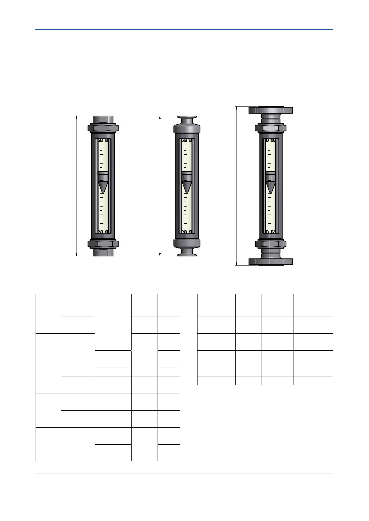
Installation length :
Process connection Thread Clamp Flange
Length [mm] 375 375 425
Weight : Depending on design (see page 7)
Accuracy :
Tube Measuring accuracy acc.
Directive VDI/VDE 3513 sheet 2 (qG= 50%)
L613 - L623 2.5%
L624 - L747 1.6%
P051 - P471 1.6%
Materials :
Threads G, NPT : AISI 316L (1.4404)
Flange EN / ASME : AISI 316L (1.4404)
Clamp ISO 2852 : AISI 316L (1.4404)
Housing : AISI 304 (1.4301)
N ut : AISI 316 (1.4401) (or galvanized steel)
Stoppers (L6, L7 tube) : PFA
Stoppers (P0 - P4 tube) : PVDF, AISI 316L (1.4404)
Measuring cone : Borosilicate glass
Float (L6, L7 tube ) : Titanium, PVDF
Float (P0 - P4 tube) : PTFE, PVDF (FDA conform),
AISI 316Ti (1.4571)
Gaskets : NBR, FKM,EPDM (FDA conform)
OPTION SPECIFICATIONS
Limit switch (option /GM1 to /GM5):
( for P- tubes with PVDF- or SS- oat with magnet only)
Type : reed contact with bistable switching
Max. switching voltage : 230 V
Max. switching current : 2 A
Max. switching capacity : 40 W/VA
Temperature range : -10°C to +70°C
Protection : IP65
Internal capacity : 0 nF
Internal inductivity : 0 mH
Electrical connection : LIYY 2 x 0.34 mm²; length 1 m
Housing : Polystyrene
Weight : 35 g
Explosion proof :
Intrinsic safe acc. EN 60079-11 chapter 5.7,
IEC 60079-11 chapter 5.7 and ANSI/ISA 60079-11
chapter 5.7 as "Simple Apparatus".
Group : IIC
Category : 2G
Temperature class : T6
Entity parameter : Ui = 15 V ; Ii = 50 mA ; Pi = 187 mW
Li ≈ 0 mH ; Ci ≈ 0 nF
Limit switch (option /GR2 to /GR8):
(for L- tubes with PVDF oat only)
Type : Bistable inductive ring sensor
Power supply : 4.5 V to 15 V DC
Consumption : acc. DIN EN 60947-5-6 (NAMUR)
Float below ring sensor : < 1 mA
Float above ring sensor : > 2.2 mA
Temperature range : -25°C to +65°C non-Ex- type
Protection : IP 67
Electrical connection : 2 x 0.14 mm² , with shield 0.4 mm²,
2 m long
Explosion proof type (option /KS1):
Temperature range : -25°C to +60°C
Marking acc. guideline 94/9/EG :
Manufacturer : Rota Yokogawa, Rheinstr.8,
D-79664 Wehr
Type : RI20-10K/G or RI20-17K/G
Year of production : in serial number
Protection : Ex ia
Group : IIC
Category : 2G
Temperature class : T6
Certicate No. : PTB 03ATEX 2111
Safety relevant data (see also certicate for data):
Ui = 12 V, Ii = 22 mA , Pi = 66 mW,
Li = 20 mH, Ci = 200 nF
Pressure Equipment Directive (PED) Directive 97/23/EG:
Models : RAGN04, RAGN05, RAGN06
Tubes :
- Modul : A
- Fluid Group : 1 (liquid, gases)
- Produced acc. to category
: I
FDA-Conformity:
RAGN with P- tube, PVDF- or SS- oat and EPDM- gaskets
(option /ME).
Stoppers and oats made of PVDF:
21 CFR § 177 2510(a)
O-rings made of EPDM:
21 CFR § 177 2600-21
Compliance with safety application acc. IEC 61508: 2010
and ISO 13849:
Please refer to the FMEDA report and instruction manual.
All Rights Reserved. Copyright © 2011, Rota Yokogawa
CE-marking
: II 2 G
Power supply for limit switch (option /W__):
Type :
acc.
DIN EN 60947-5-6 (NAMUR)
- KFA5-SR2-Ex*-W (115 V AC),
- KFA6-SR2-Ex*-W (230 V AC),
* = 1 or 2
* = 1 or 2
- KFD2-SR2-Ex*-W (24 V DC), * = 1 or 2
- KHA6-SH-Ex1 (115/230 V AC), Fail Safe, 1 channel
- KFD2-SH-Ex1 (24 V DC), Fail Safe, 1 channel
Power supply :
- 230 V AC ± 10%, 45-65Hz
- 115 V AC ± 10%, 45-65Hz
- 24 V DC ± 25%
Relay output :
1 or 2 potential-free changeover contact(s)
Switching capacity :
max. 250 V AC, max. 2 A
IM 01R01B10-00E-E 2nd edition: November 01, 2011-00
Page 34
8-2
<8. TECHNICAL DATA>
Explosion proof : Intrinsic safe [Ex ia] IIC
PTB 00 ATEX 2081 (/W1A, /W1B, /W2A, /W2B)
PTB 00 ATEX 2080 (/W4A, /W4B)
PTB 00 ATEX 2042 (/W4E, /W4F)
PTB 00 ATEX 2043 (/W2E, /W2F)
Note :
For safety application fail safe power
W2F, /W4E or /W4F must be selected in combination with
options /GR_.
MODEL SPECIFICATIONS
Model Suffix code Description Restrictions
RAGN01
RAGN23
RAGN02
RAGN04
RAGN05
RAGN06
Process
connection
Material of process
connections
Metering tube
Diameter of metering tube 1)6
Cone
Float material
Diameter of oat
Medium / Float factor
Float insertion
1)
Combinations see tables on page 8-3 and 8-4
-D4
-A1
-G0
-T0
-S4
SS Stainless steel
1)
1)
1)
1)
-L
-P
7
0
1
2
4
13
14
17
21
22
23
24
27
31
32
33
34
37
41
42
43
44
47
51
52
53
54
57
61
62
63
64
67
71
-SS
-PF
-PD
-TT
1)
1)
A
B
C
D
0
1
2
4
L
G
2
3
6
7
IM 01R01B10-00E-E 2nd edition: November 01, 2011-00
Size DN 15 (½ inch)
Size DN 20 (¾ inch)
Size DN 25 (1 inch)
Size DN 40 (1½ inch)
Size DN 50 (2 inch)
Size DN 65 (2½ inch)
EN ange PN 40, process connection dimension +
facing acc. EN 1092-2 Form B1
ASME ange class 150, process connection dimension
+ facing acc. ASME B 16.5
Inner thread G
Inner thread NPT
Clamp ISO 2852
L-tube (300 mm)
P-tube (300 mm)
10 mm
17 mm
20 mm
34 mm
48 mm
81 mm
1.4571 / AISI 316 Ti
PTFE
PVDF
Titanium
1.59
3.18
6.35
9.53
12.2 (P0-oat)
21.6 (P1-oat)
31.2 (P2-oat)
54.1 (P4-oat)
For liquid
For gas
For water
For water
For air
For air
NMWithout magnet
With magnet
All Rights Reserved. Copyright © 2011, Rota Yokogawa
for D4, A1, G0, T0, S4 with L6, L7, P0, P1
for G0, T0 with L6, L7, P0, P1
for D4, A1, G0, T0, S4 with L6, L7, P0, P1, P2
for D4, A1, G0, T0 with P2, P4
for D4, A1, with P2, P4; for G0, T0 with P4
for G0, T0 with P4
supply option /W2E, /
Page 35
<8. TECHNICAL DATA>
FLOW TABLE WITH METERING TUBE-FLOAT-COMBINATION FOR WATER / LIQUIDS
Flow table Suffix code metering tube - oat- combination
Water / liquids 20°C Metering tube Float
-x x xx -xx x x x
Max.
Flow
[l/h]
0.025 1 L 6 13
0.04 1 L 6 14
0.063 2 L 6 17
0.1 2 L 6 21
0.16 3 L 6 22
0.25 4 L 6 23
0.4 1 L 6 24
0.63 1 L 6 27
1 2 L 6 31
1. 6 3 L 6 32
2.5 4 L 6 33
4 2 L 7 34
6.3 2 L 7 37
10 3 L 7 41
16 4 L 7 42
25 5 L 7 43
40 5 L 7 44
63 10 L 7 47
63 10 P 0 51
100 16 P 0 52
100 16 P 0 51
160 24 P 0 52
160 15 P 1 53
250 16 P 1 54
400 18 P 1 57
630 26 P 1 61
250 15 P 1 53
400 16 P 1 54
630 18 P 1 57
1000 26 P 1 61
1000 11 P 2 62
1600 13 P 2 63
1600 26 P 2 62
2500 30 P 2 63
2500 16 P 4 64
4000 18 P 4 67
6300 21 P 4 71
4000 40 P 4 64
6300 44 P 4 67
10000 53 P 4 71
Length metering tube 300 mm .....................
Diam. metering tube 10 mm to 81 mm .......................... x
Cone metering tube See ow table .................................................. xx
Float material 1.4571 ..................................................................................
Float diameter 1.6 mm to 54 mm .................................................................................... x
Flow mark For liquid .....................................................................................................................
Float insertion Without magnet ..............................................................................................................................
1)
Max. viscosity 2 mPas*s
2)
For option limit switch /GM1 to /GM5
Pressure loss
Length
Diameter
Cone
Material
Diameter
Flow
mark
[mbar]
Code
Code
Code
Code
TT A
Code
Code
1)
L
B L
TT;PD
C L
D L
PD
2 M
0
SS 3
PD
2 M
1
SS 3
PD
2 M
2
SS 3
PD
2 M
4
SS 3
Description
P
300 mm .....................
L
SS
Titanium ...............................................................................
PTFE ....................................................................................
PVDF ...................................................................................
TT
PF
PD
L
For water ......................................................................................................................
For water ......................................................................................................................
2
3
With magnet ...................................................................................................................................
Insertion
Code
N
M 2);
N
M 2);
N
M 2);
N
M 2);
N
N
2)
M
8-3
All Rights Reserved. Copyright © 2011, Rota Yokogawa
IM 01R01B10-00E-E 2nd edition: November 01, 2011-00
Page 36

8-4
<8. TECHNICAL DATA>
FLOW TABLE WITH METERING TUBE-FLOAT-COMBINATION FOR AIR / GASES
Flow table Suffix code metering tube - oat- combination
Air/Gases 20°C, 1 bar abs Metering tube Float
-x x xx -xx x x x
Max. Flow
[l/h]
1. 9 1 L 6 13
3 1 L 6 14
4.4 2 L 6 17
6.5 2 L 6 21
10 3 L 6 22
14 4 L 6 23
23 2 L 6 24
33 2 L 6 27
50 2 L 6 31
70 3 L 6 32
100 4 L 6 33
180 3 L 7 34
250 3 L 7 37
400 3 L 7 41
630 4 L 7 42
1000 5 L 7 43
1600 5 L 7 44
2400 10 L 7 47
1600 4 P 0 51
2500 6 P 0 52
2400 8 P 0 51
3800 11 P 0 52
6000 6 P 1 53
9300 7 P 1 54
14500 8 P 1 57
23000 10 P 1 61
400 5 P 1 53
6300 5 P 1 54
10000 6 P 1 57
16000 8 P 1 61
35000 11 P 2 62
55000 13 P 2 63
25000 8 P 2 62
40000 10 P 2 63
88000 29 P 4 64
140000 32 P 4 67
220000 34 P 4 71
63000 13 P 4 64
100000 14 P 4 67
160000 17 P 4 71
Length metering tube 300 mm .....................
Diam. metering tube 10 mm to 81 mm .......................... x
Cone metering tube See ow table .................................................. xx
Float material Titanium ...............................................................................
Float diameter 1.6 mm to 54 mm .................................................................................... x
Flow mark For gas .......................................................................................................................
Float insertion Without magnet ..............................................................................................................................
1)
For option limit switch /GM1 to /GM5
Pressure loss
Length
Diameter
Cone
Material
Diameter
Flow
mark
[mbar]
Code
Code
Code
Code
Code
Code
TT A G
B G
PD;TT
C G
D G
PF
6
0
PD 7 M
PD 1 7 M
PF 1 6 N
PD 2 7 M
PF 2 6 N
PD 4 7 M
PF 4 6 N
Description
300 mm ..................... PL
TT
PTFE ....................................................................................
PVDF ...................................................................................
PF
PD
G
For air ..........................................................................................................................
For air ..........................................................................................................................
6
7
With magnet ...................................................................................................................................
Insertion
Code
N
1)
1)
1)
1)
N
1)
M
IM 01R01B10-00E-E 2nd edition: November 01, 2011-00
All Rights Reserved. Copyright © 2011, Rota Yokogawa
Page 37

<8. TECHNICAL DATA>
8-5
OPTIONS
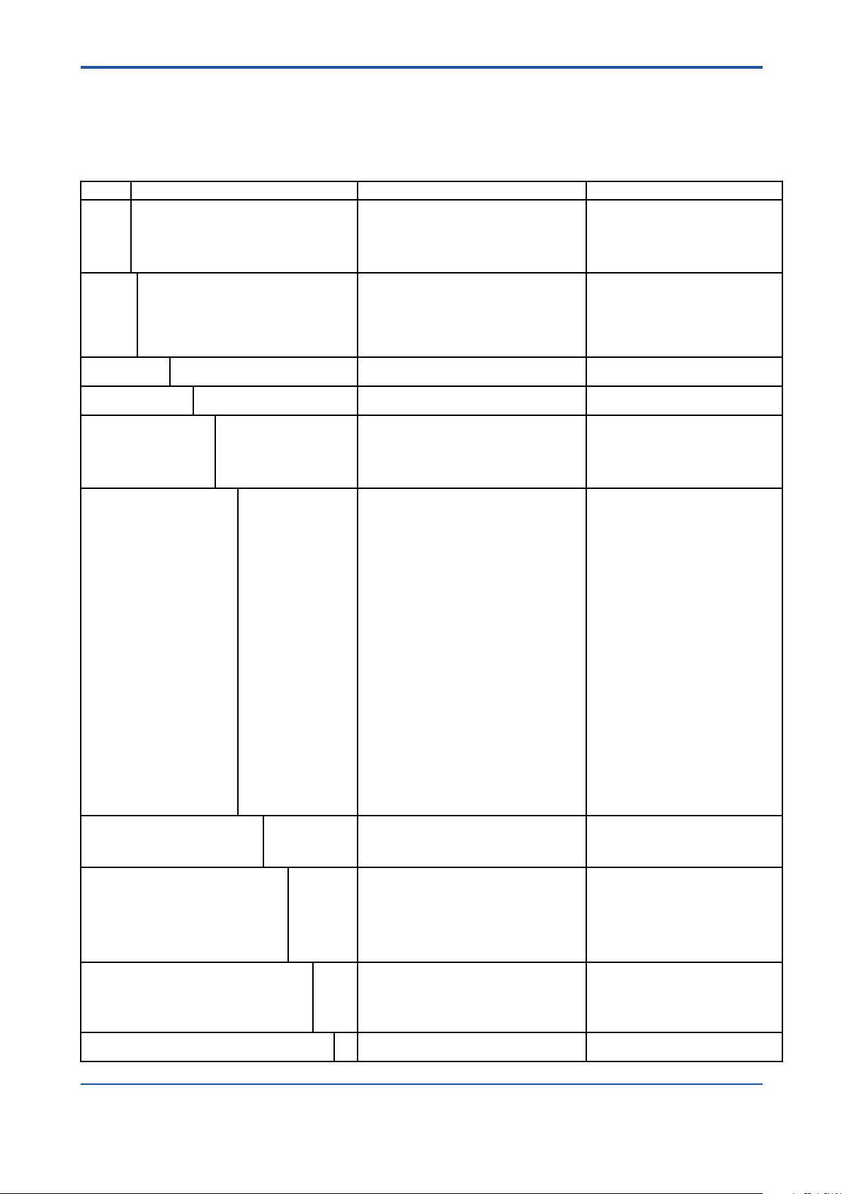
Options Option
Marking /B1
Limit switches /GM1
Ex-proof type /KS1 ATEX intrinsically safe „ia“ Only for /GR2 to /GR8
Installation lengths
(s. also table on page 8-6)
Valves
(inner thread,
double tting is attached,
not for FDA)
Test and certicates /H1
Delivery to Korea /KC With KC-mark in Korea
Accessories for metering
tube
Power supply for limit
switches (transmitter
relay)
Instruction manuals /IEn
Special order /Z Special design must be specied in an extra text.
*) If no instruction manual is selected, only a Short IM and in case of limit switches a CD with instruction manuals is shipped with the owmeter.
Code
/B4
/BG
/B10
/BD
/GM2
/GM3
/GM4
/GM5
/GR2
/GR3
/GR4
/GR6
/GR7
/GR8
/GD1
/GD2
/L12
/L13
/L14
/L15
/L16
/V1
/V2
/V3
/V4
/V5
/V6
/P2
/P3
/P6
/PP
/PT
/PM2
/PM4
/MV
/ME
/MN
/W1A
/W1B
/W2A
/W2B
/W2E
/W2F
/W4A
/W4B
/W4E
/W4F
/IDn
Description Restriction
Tag plate (SS)
Neutral version
Customer specic notes on name plate
Percentage scale
Dual scale
Magnetic MIN-contact
Magnetic MAX-contact
Magnetic MIN-MAX-contact
Magnetic MIN-MIN-contact
Magnetic MAX-MAX-contact
Bistable inductive ring sensor
Bistable inductive ring sensor
Bistable inductive ring sensor
2 bistable inductive ring sensors
2 bistable inductive ring sensors
2 bistable inductive ring sensors
Connection box for 1 limit switch
Connection box for 2 limit switches
Installation length 500 mm
Installation length 356 mm
Installation length 368 mm
Installation length 386 mm
Installation length 394 mm
Valve made of 1.4571 G ½´´ (parts attached)
Valve made of 1.4571 G 1´´ (parts attached)
Valve made of 1.4571 G 1½´´ (parts attached)
Valve made of brass G ½´´ (parts attached)
Valve made of brass G 1´´ (parts attached)
Valve made of brass G 1½´´ (parts attached)
Oil + fat free for wetted surfaces acc. Yokogawa specication
Certicate of Compliance with the order acc. EN 10204: 2004- 2.1
As /P2 +Test report acc. to EN 10204: 2004- 2.2
Material certicate for Insertion parts or ange connections
acc. EN 10204: 2004- 3.1
Pressure test report for metering system
With ow table for recalculation + mm- scale
PAMI test (2 test points)
PAMI test (4 test points)
Gasket FKM (Viton)
Gasket EPDM (conform to FDA, -30°C to +100°C)
Nut galvanized steel
KFA5-SR2-Ex1.W / 115 V AC, 1 channel
KFA5-SR2-Ex2.W / 115 V AC, 2 channel
KFA6-SR2-Ex1.W / 230 V AC, 1 channel
KFA6-SR2-Ex2.W / 230 V AC, 2 channel
KHA6-SH-Ex1 / 115/230 V AC, 1 channel, Fail Safe
2x KHA6-SH-Ex1 / 115/230 V AC, 1 channel, Fail Safe
KFD2-SR2-Ex1.W / 24 V DC, 1 channel
KFD2-SR2-Ex2.W / 24 V DC, 2 channel
KFD2-SH-Ex1 / 24 V DC, 1 channel, Fail Safe
2x KFD2-SH-Ex1 / 24 V DC, 1 channel, Fail Safe
Quantity of instruction manuals in English
Quantity of instruction manuals in German
Plate 12 x 40 mm; max. 45 digits
Not with /KS1
Max. 45 digits
Only for tube P
Only for tube P0 to P4 and oat
insertion code M (with magnet)
Only for tube P0 to P4 and oat
insertion code M (with magnet)
Only for tube P0 to P4 and oat
insertion code M (with magnet)
Only for tube P0 to P4 and oat
insertion code M (with magnet)
Only for tube P0 to P4 and oat
insertion code M (with magnet)
Only for tube L6 with oat code PDB
Only for tube L7 with oat code PDC
Only for tube L7 with oat code PDD
Only for tube L6 with oat code PDB
Only for tube L7 with oat code PDC
Only for tube L7 with oat code PDD
Only with /GM1 to 2, /GR2 to 4
Only with /GM3 to 5, /GR6 to 8
Only for D4, A1
Only for size 01 and G0, T0
Only for size 01, 23, 02 and G0, T0
Only for size 02, 04 and G0, T0
Only for size 05, 06 and G0, T0
Only for G0 and tube L6, L7, P0
Only for G0 and tube P1
Only for G0 and tube P2
Only for G0 and tube L6, L7, P0
Only for G0 and tube P1
Only for G0 and tube P2
Only for insertion and ange
connections
Not with /V1 to /V6
Only for connections G0, T0, S4
except RAGN04-G0SS-P2 and
RAGN04-T0SS-P2
Only for connections A1, D4 and
RAGN04-G0SS-P2 and
RAGN04-T0SS-P2
conform with FDA -30°C to +100°C
not for S4 and RAGN04 with P2
n = 1 to 9 selectable *)
n = 1 to 9 selectable *)
All Rights Reserved. Copyright © 2011, Rota Yokogawa
IM 01R01B10-00E-E 2nd edition: November 01, 2011-00
Page 38
8-6
1
2
4
6
8
0101
6
2
1
4
8
10
6
2
1
4
8
L
L
L
Inner thread type (T0; G0) Clamp type (S4) Flange type (D4; A1)
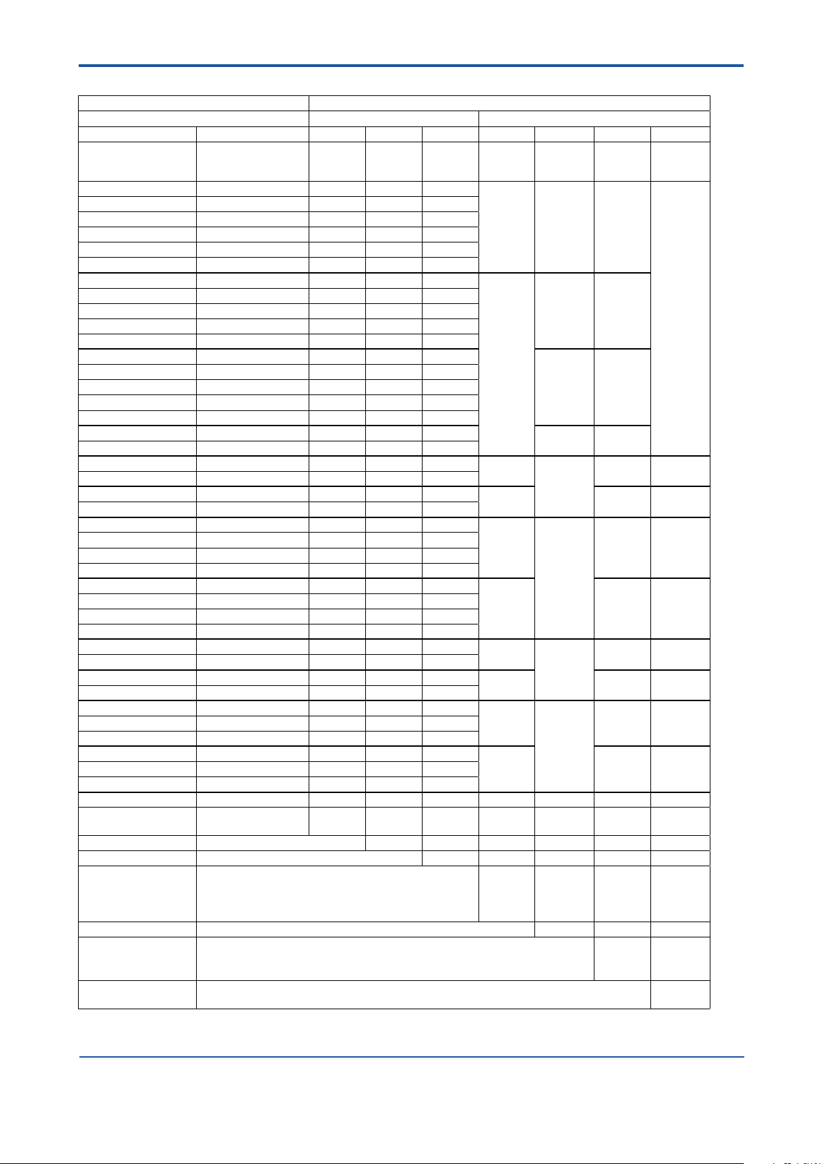
<8. TECHNICAL DATA>
PROCEDURE TO SELECT THE MODEL CODE
Please specify in the following order
- Measuring range for water/liquid or air/gas
- With or without optional limit switch
First select the required measuring range from the ow table (last column) and specify the oat insertion for the optional limit switch.
Then the suffix code for the combination metering tube - oat can be xed.
To size the Rotameter for other medium - process- conditions use sizing program Durep V.
DIMENSIONS
METERING TUBE
Installation lengths and weights:
Model Process
RAGN01
RAGN23 Inner thread 375 1. 7
RAGN02
RAGN04
RAGN05
RAGN06 Inner thread P4 375 7. 7.1 1
connection
Inner thread
Clamp 375 1. 9
Flange 425 2.5
Inner thread
Clamp
Flange
Inner thread
Flange
Inner thread P4 375 7. 1
Flange
Tube Length LmmWeight
375 1. 7
L6; L7; P0; P1
L6; L7; P0; P1
P2 2.6
L6; L7; P0; P1 2.0
P2 2.8
L6; L7; P0; P1
P2 3.9
P2
P4 7. 1
P2
P4 8.7
P2
P4 11. 1
375
425
375
425
425
kg
1. 7
3.3
2.6
5.2
6.6
Compatibility with former Rotameter RAGG / RAGH:
Former model Tube Installation
length mm
RAGH01 L6;L7;G0 356 RAGN01..../L13
RAGH02 G1 368 RAGN02..../L14
RAGH04 G2 386 RAGN04..../L15
RAGH06 G4 394 RAGN06..../L16
RAGH23 G1 368 RAGN23..../L14
RAGH05 G4 394 RAGN05..../L16
RAGG01 G0;G1 500 RAGN01..../L12
RAGG02 G2 500 RAGN02..../L12
RAGG04 G4 500 RAGN04..../L12
Model RAGN
IM 01R01B10-00E-E 2nd edition: November 01, 2011-00
All Rights Reserved. Copyright © 2011, Rota Yokogawa
Page 39
e
d
b
c
a
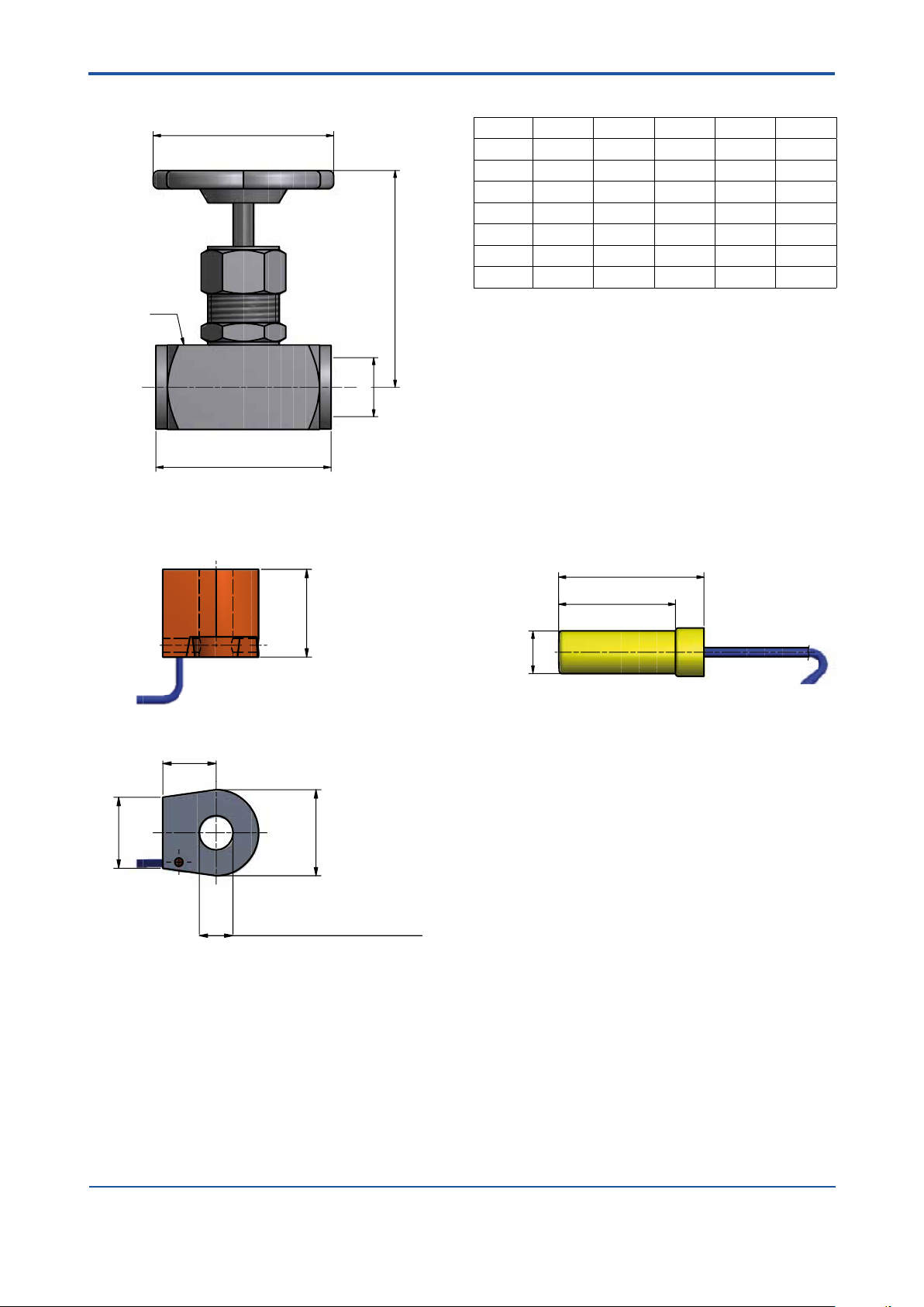
VALVE /Vx
2
1
2
5
.5
2
6
16 /GR2, /GR6
19.5 /GR3, /GR4, /GR7, /GR8
Ø 10.1 /GR2 /GR6
Ø 17.1 /GR3, /GR4, /GR7, /GR8
Ø
1
4
41
51
<8. TECHNICAL DATA>
Option a b c d e
Thread mm mm mm mm
/V1 G ½´´ 60 88 SW 30 63
/V2 G 1´´ 100 11 0 SW 45 90
/V3 G 1½´´ 130 145 SW 70 100
/V4 G ½´´ 55 78 SW 25 63
/V5 G 1´´ 75 93 SW 41 63
/V6 G 1½´´ 11 0 118 SW 60 90
8-7
LIMIT SWITCH /GRx LIMIT SWITCH /GMx
All Rights Reserved. Copyright © 2011, Rota Yokogawa
IM 01R01B10-00E-E 2nd edition: November 01, 2011-00
Page 40

8-8
<8. TECHNICAL DATA>
Blank Page
IM 01R01B10-00E-E 2nd edition: November 01, 2011-00
All Rights Reserved. Copyright © 2011, Rota Yokogawa
Page 41
<A1. SAFETY INSTRUMENTED SYSTEMS INSTALLATION>
WARNING
A1-1
APPENDIX 1. Safety Instrumented
Systems Installation
The contents of this appendix are cited from exida.com safety manual on the Rotameter RAGN Flowmeter
specically observed for the safety transmitter purpose. When using the RAGN for Safety Instrumented
Systems (SIS) application, the instructions and procedures in this section must be strictly followed in order
to preserve the meter for that safety level.
A1.1 Scope and Purpose
This document provides an overview of the user responsibilities for installation and operation of the Rota
Yokogawa RAGN variable area ow meter, herein referred to as RAGN Glass Rotameter, in order to maintain
the designed safety level. Items that will be addressed are proof testing, repair and replacement of the ow
meter, reliability data, lifetime, environmental and application limits, and parameter settings.
A1.2 Using RAGN for a SIS Application
A1.2.1 Safety Function
Suitable for use in Safety Instrumented Systems are the versions listed in table 1 only. The safety related data
listed in this manual does not apply to other versions of RAGN.
Table 1 Versions of RAGN suitable for Safety Instrumented Systems
[V1] RAGN with Reed-switch(es)
[V2] RAGN with Ring Initiator, fail-safe state: LOW
[V3] RAGN with Ring Initiator, fail-safe state: HIGH
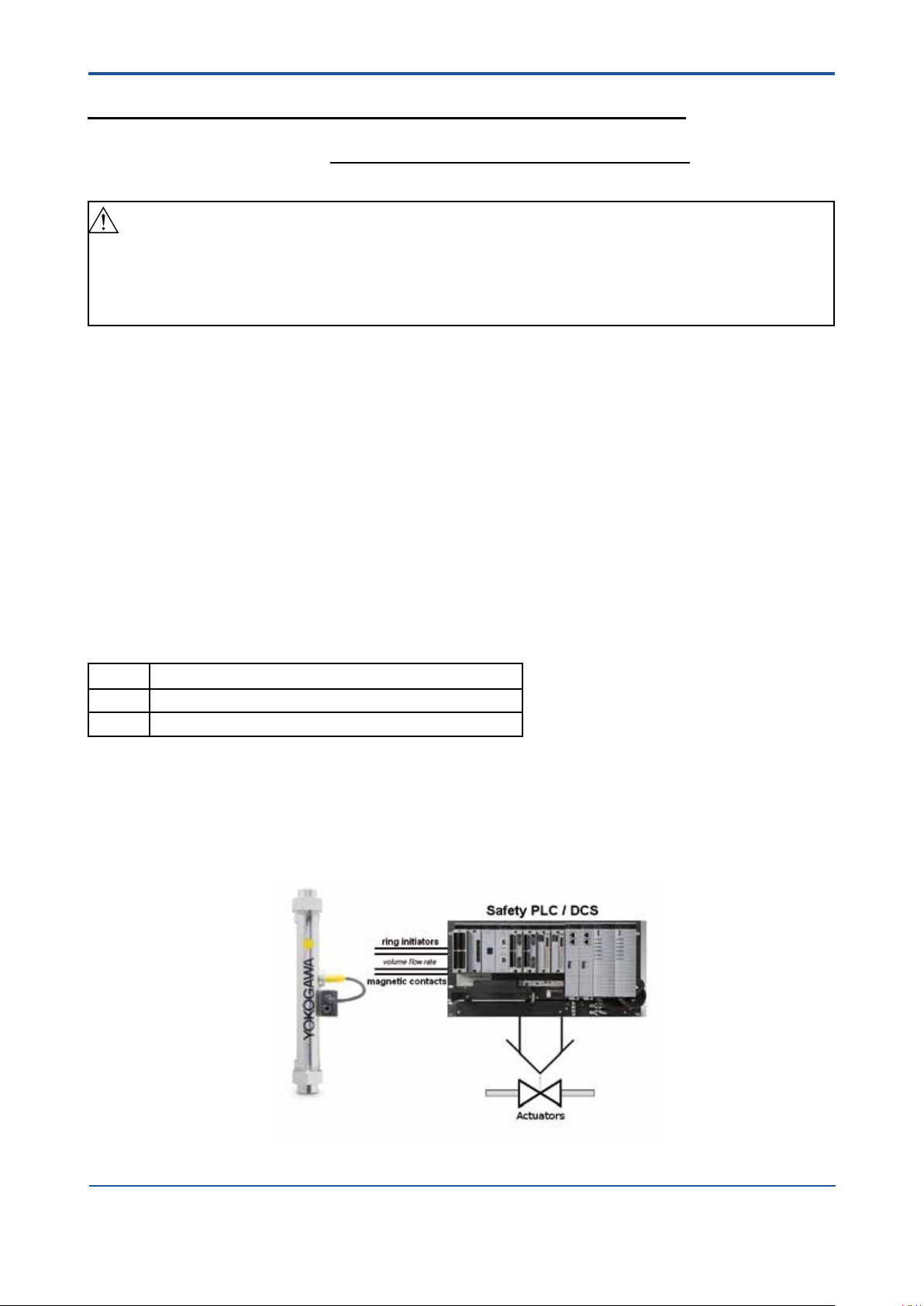
This variable area ow meter is intended for use as a volume ow monitoring component in a Safety
Instrumented System. It has either inductive ring sensors [V2], [V3] or magnetic reed contacts [V1] to indicate
limits. The ow meter may be used with the limit switches to feed signals to a logic solver that is part of the
safety instrumented function (SIF) as shown in Figure 1. The fault annunciation mechanism is a trip of one
of the limit switches. In order to take credit for the automatic diagnostics in the ow meter, this annunciation
mechanism must be connected.
Any valve delivered together with RAGN Glass Rotameter is not covered by the assessment.
Figure 1 Example Safety Instrumented Function
All Rights Reserved. Copyright © 2011, Rota Yokogawa
IM 01R01B10-00E-E 2nd edition: November 01, 2011-00
Page 42

A1-2
<A1. SAFETY INSTRUMENTED SYSTEMS INSTALLATION>
A1.2.2 Diagnostic Response Time
There is neither diagnostic in the magnetic reed contacts [V1] nor in the inductive ring sensors [V2], [V3].
A1.2.3 Setup
A setup of the ow meter is not required. Installation shall be done according to the manual.
Precautions for use of ring sensors [V2], [V3] in Safety Instrumented Functions:
The high output current should be used as the preferred “safe state”. Therefore to achieve highest reliability of
the system, the orientation of the ring sensors should be set according to the application to set high current
as safe state. For more information on assembly see User’s Manual, Model RAGN Glass Rotameter,
IM 01R01B10-00E-E.
A1.2.4 Proof Testing
The objective of proof testing is to detect failures within the ow meter. Of main concern are undetected
failures that prevent the safety instrumented function from performing its intended function.
The frequency of the proof tests (or the proof test interval) is to be determined in the reliability calculations
for the safety instrumented functions for which the ow meter is applied. The actual proof tests must be
performed more frequently or as frequently as specied in the calculation in order to maintain required safety
integrity of the safety instrumented function.
The following tests need to be specically executed when a proof test is performed. The results of the proof
test need to be documented and this documentation should be part of a plant safety management system.
Failures that are detected should be reported to Yokogawa.
Proof test for RAGN Glass Rotameter with magnetic contacts and inductive ring sensors:
Step Action
1 Take appropriate action to avoid a false trip
2 Inspect the device for any visible damage, corrosion or contamination.
3a Force the RAGN Glass Rotameter to reach a dened “MAX” threshold value and verify that the
magnetic contact or inductive ring initiator goes into the safe state.
Note: only applicable if RAGN is equipped with a “MAX” contact.
3b Force the RAGN Glass Rotameter to reach a dened “MIN” threshold value and verify that the
magnetic contact or inductive ring initiator goes into the safe state.
Note: only applicable if RAGN is equipped with a “MIN” contact.
4 Restore the loop to full operation
5 Restore normal operation
When all the tests listed above are executed a proof test coverage of approximately 99% of possible DU
failures in the RAGN Glass Rotameter can be claimed.
The following tools need to be available to perform proof testing:
Measurement instrument to verify output status of the magnetic reed contacts [V1] or inductive ring sensors
[V2], [V3]
The person(s) performing the proof test of the Yokogawa RAGN Glass Rotameter should be trained in SIS
operations including bypass procedures, ow meter maintenance and company management of change
procedures.
A1.2.5 Repair and replacement
Maintenance information can be found in section Service of the User’s Manual, Model RAGN Glass
Rotameter, IM 01R01B10-00E-E.
If repair is to be performed with the process online the Rota Yokogawa RAGN Glass Rotameter will need to
be bypassed during the repair. The user should setup appropriate bypass procedures for that.
Contact the Yokogawa sales office if this instrument requires repair
The person(s) performing the repair and / or replacement of the Rota Yokogawa RAGN Glass Rotameter
should have a sufficient skill level.
IM 01R01B10-00E-E 2nd edition: November 01, 2011-00
All Rights Reserved. Copyright © 2011, Rota Yokogawa
Page 43

<A1. SAFETY INSTRUMENTED SYSTEMS INSTALLATION>
A1-3
A1.2.6 Startup Time
The ow meter will generate a valid signal within 0.5 seconds of power-on startup.
A1.2.7 Reliability data
A detailed Failure Mode, Effects, and Diagnostics Analysis (FMEDA) report is available from Rota Yokogawa
with all failure rates and failure modes. Rota Yokogawa RAGN Glass Rotameter is intended for use in a Low
Demand Mode. Low Demand Mode means the average interval between dangerous conditions occurs
infrequently.
The Rota Yokogawa RAGN Glass Rotameter is certied up to SIL1 for use in a simplex (1oo1) conguration,
depending on the PFDAVG calculation of the entire Safety Instrumented Function.
A1.2.8 Lifetime limits
The expected lifetime of the Yokogawa Rota Yokogawa RAGN Glass Rotameter is 10 years. The reliability
data listed in A1.2.7 is only valid for this period. The failure rates of the Rota Yokogawa RAGN Glass
Rotameter may increase sometime after this period. Reliability calculations based on the data listed in A1.2.7
for Rota Yokogawa RAGN Glass Rotameter lifetimes beyond 10 years may yield results that are too optimistic,
i.e. the calculated Safety Integrity Level will not be achieved.
A1.2.9 Environmental limits
The environmental limits of Rota Yokogawa RAGN variable area ow meter are specied in the User’s
Manual, Model RAGN Glass Rotameter, IM 01R01B10-00E-E.
A1.2.10 Application limits
The application limits of the Rota Yokogawa RAGN variable area ow meter are specied in the User’s
Manual, Model RAGN Glass Rotameter, IM 01R01B10-00E-E. If the ow meter is used outside of the
application limits the reliability data listed in A1.2.7 becomes invalid.
All Rights Reserved. Copyright © 2011, Rota Yokogawa
IM 01R01B10-00E-E 2nd edition: November 01, 2011-00
Page 44

A1-4
<A1. SAFETY INSTRUMENTED SYSTEMS INSTALLATION>
A1.3 Denitions and Abbreviations
A1.3.1 Denitions
Safety Freedom from unacceptable risk of harm
Functional Safety The ability of a system to carry out the actions necessary to achieve or to maintain a
dened safe state for the equipment / machinery / plant / apparatus under control of
the system.
Basic Safety The equipment must be designed and manufactured such that it protects against
risk of damage to persons by electrical shock and other hazards and against
resulting re and explosion. The protection must be effective under all conditions of
the nominal operation and under single fault condition.
Verication The demonstration for each phase of the life-cycle that the (output) deliverables of
the phase meet the objectives and requirements specied by the inputs to the
phase. The verication is usually executed by analysis and / or testing.
Validation The demonstration that the safety-related system(s) or the combination of safety-
related system(s) and external risk reduction facilities meet, in all respects, the
Safety Requirements Specication. The validation is usually executed by testing
Safety Assessment The investigation to arrive at a judgment - based on evidence - of the safety
achieved by safety-related systems
Further denitions of terms used for safety techniques and measures and the description of safety related
systems are given in IEC 61508-4.
A1.3.2 Abbreviations
FMEDA Failure Mode, Effects and Diagnostic Analysis
SIF Safety Instrumented Function
SIL Safety Integrity Level
SIS Safety Instrumented System
SLC Safety Lifecycle
A1.4 Assessment results
A1.4.1 Safety related parameters
The following results have been obtained from the assessment report Report No.: ROTA YOKOGAWA 11/0436 R004 Version V1, Revision R1; November 2011 issued by exida.
Average PFD values have been calculated assuming a Diagnostic Coverage (DC) of 99%, a mission time of
10 years and a Mean Time to Restoration of 24 hours.
IM 01R01B10-00E-E 2nd edition: November 01, 2011-00
All Rights Reserved. Copyright © 2011, Rota Yokogawa
Page 45

<A1. SAFETY INSTRUMENTED SYSTEMS INSTALLATION>
Table 2: Summary for RAGN – Failure rates
exida Prole 2
Version
[V1]
Reed contacts
Fail-safe state LOW
[V2]
[V3]
Fail-safe state HIGH
Fail Safe Detected (lSD) 0 FIT 0 FIT 0 FIT
Fail Safe Undetected (lSU) 20 FIT 2 FIT 11 FIT
Fail Dangerous Detected (lDD) 0 FIT 11 FIT 11 FIT
Fail Dangerous Undetected (lDU) 87 FIT 139 FIT 130 FIT
3
SFF
18% 8% 14%
MTBF 1035 years 738 years 738 years
SIL AC
4
SIL1 SIL1 SIL1
Safety metrics according to ISO 13849-1:
MTTFd (years) 1312 761 809
5
DC
0% 7% 8%
Category (CAT) CAT 1 CAT 1 CAT 1
Performance Level (required) PLr = c PLr = c PLr = c
Performance Level (calculated) 8.70E-08 1/h 1.50E-07 1/h 1.41E-07 1/h
PFDAVG, T[Proof] = 1 year 4.12E-04 6.61E-04 6.18E-04
PFDAVG, T[Proof] = 5 years 1.91E-03 3.06E-03 2.86E-03
PFDAVG, T[Proof] = 10 years 3.78E-03 6.07E-03 5.67E-03
A1-5
3
The complete sensor subsystem will need to be evaluated to determine the overall Safe Failure Fraction.
The number listed is for reference only.
4
SIL AC (architectural constraints) means that the calculated values are within the range for hardware
architectural constraints for the corresponding SIL but does not imply all related IEC 61508 requirements
are fullled.
5
The switching contact output of [V2], [V3] is connected to a fail-safe NAMUR amplier (e.g. Pepperl+Fuchs
KF**-SH-Ex1). The failure rates of the amplier are not included in the listed failure rates
All Rights Reserved. Copyright © 2011, Rota Yokogawa
IM 01R01B10-00E-E 2nd edition: November 01, 2011-00
Page 46

Yokogawa has an extensive sales and
distribution network.
Please refer to the European website
(www.yokogawa.com/eu) to contact your
nearest representative.
Euroweg 2
3825 HD AMERSFOORT
The Netherlands
www.yokogawa.com/eu
YOKOGAWA ELECTRIC CORPORATION
World Headquarters
9-32, Nakacho 2-chome, Musashino-shi
Tokyo 180-8750
Japan
www.yokogawa.com
YOKOGAWA CORPORATION OF AMERICA
2 Dart Road
Newnan GA 30265
USA
www.yokogawa.com/us
YOKOGAWA ELECTRIC ASIA Pte. LTD.
5 Bedok South Road
Singapore 469270
Singapore
www.yokogawa.com/sg
YOKOGAWA CHINA CO. LTD.
3F Tower D Cartelo Crocodile Building
No.568 West Tianshan Road Changing District
Shanghai, China
www.yokogawa.com/cn
YOKOGAWA MIDDLE EAST B.S.C.(c)
P. O. Box 10070, Manama
Building 577, Road 2516, Busaiteen 225
Muharraq, Bahrain
www.yokogawa.com/bh
RotameterTM is a trademark of Rota Yokogawa GmbH & Co. KG, a subsidiary of Yokogawa Electric Corporation, Japan. In the United Kingdom Rotameter
Emerson Electric Co.
All Rights Reserved. Copyright © 2011, Rota Yokogawa
IM 01R01B10-00E-E 2nd edition: November 01, 2011-00
Subject to change without notice
TM
is a trademark of
 Loading...