

Page 1
General
Specications
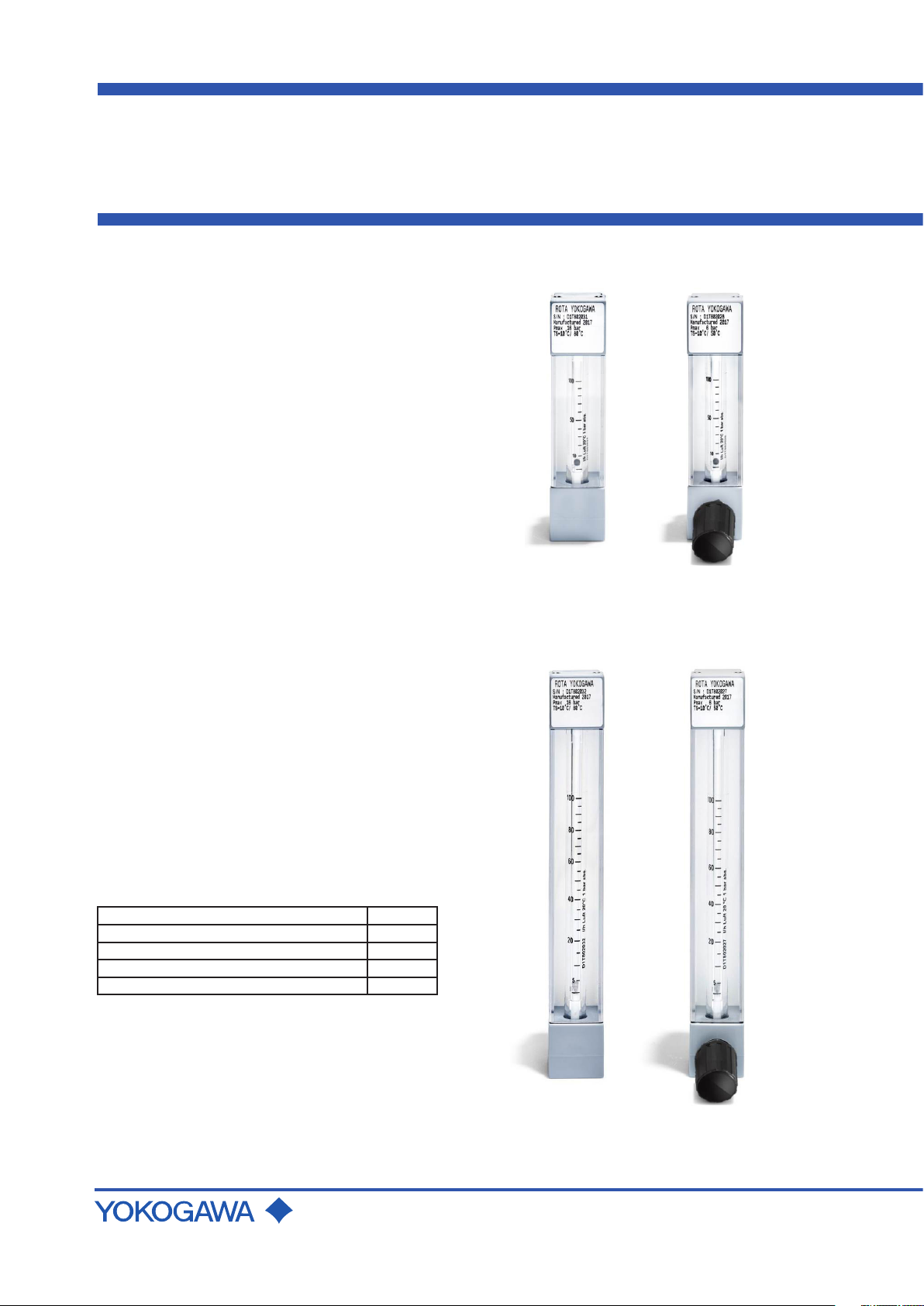
Model RAGK
Small Glass ROTAMETER
GS 01R01B07-00E-E
Rotameter RAGK is designed for the measurement of
clean liquids and gases.
The conical glass metering tube has a free rotating
oat. The Rotameter is mounted in a vertical pipeline
with ow direction upwards. The ow is indicated by
the top of the oat and can be read from a scale on
the measuring tube or from an attached scale.
FEATURES
• Large selection of measuring ranges
• High repeatability by a free rotating oat even at low
ow rates
• Low pressure loss
• Visual check of the medium
• Non-powered local indication
• Large selection of scales
• Optional built-in regulation valve
• Optional limit switches
Typical Applications
• Transparent liquids
• Low viscous liquids
• Gases
RAGK41 with K-tube
without valve with valve
Contents
Features page 1
Standard Specications page 2
Model Specications page 6
Options
Dimensions and weights page 8
Rota Yokogawa GmbH & Co. KG
Rheinstr. 8
D-79664 Wehr
Germany
page 7
RAGK41 with M-tube
without valve with valve
GS 01R01B07-00E-E
© Copyright 2004 (RYG)
15th edition, April 2020 (RYG)
Page 2
2
0 %
5 %
10 %
15 %
20 %
25 %
30 %
35 %
40 %
45 %
0 %20 %40 %60 %80 %100 %
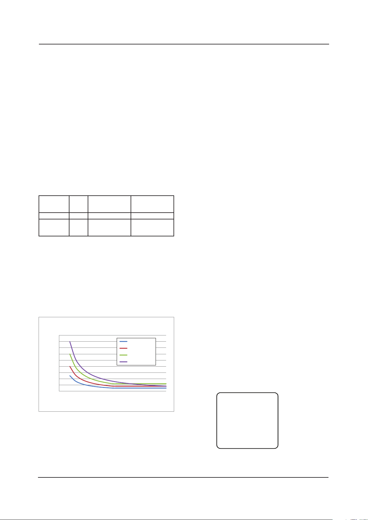
Error
Flow
Accuracy specification
2.5 %, qG=50 %
4 %, qG=50 %
6 %, qG=50 %
4 %, qG=100 %
ROTA YOKOGAWA
S/N: D1L123456
Manufactured: 2019.08
PS: 16 bar
TS: -10°C/+130°C
RAGK
FIC 1102
STANDARD SPECIFICATIONS
RoHS Directive 2011/65/EU:
RoHS conform according to EN 50581
Measurable ow rates:
• Water, 20 °C (68 °F):
0.002 l/h to 630 l/h
(0.0005 gph to 166 gph)
• Air, 20 °C (68 °F), 1 bar abs.:
0.2 l/h to 6300 l/h
(0.05 gph to 1664 gph)
The measureable ow rates are depending from
density and viscosity of the uid. To nd the uid
specic measuring range please use the Yokogawa
FlowCongurator: www.FlowCongurator.com.
Measuring range: ≈10:1
Measuring tubes: K6xx; M6xx; K7xx; M7xx; M3xx
K, M: length code
6, 7, 3: diameter code
xx: cone code
Table 1: Measuring accuracy
Glass
metering tube
K631 - K743 75 mm 4 % (for ball 6 %) -----
M613 - M622
M624 - M747
M352 - M357
For detailed accuracy calculation please use the Yokogawa
FlowCongurator: www.FlowCongurator.com.
The accuracy is given under calibration conditions. For
liquid service it has to be taken into account, that the
indication is viscosity dependent and the accuracy can
only be kept if the temperature is constant.
Calibration conditions:
Air, 18 °C to 25 °C (64.4 °F to 77 °F)
atmospheric pressure
Length Measuring accuracy
150 mm
150 mm
150 mm
acc. VDI/VDE 3513
sheet 2 (qG=50 %)
-----
2.5 %
2.5 %
Measuring accuracy
acc. VDI/VDE 3513
sheet 2 (qG=100 %)
4 %
-----
-----
Process and ambient temperature:
• Head material stainless steel(SS): -20 °C to 130 °C
(-4 °F to 266 °F)
• Head material polypropylene(PP): 0 °C to 80 °C
(32 °F to 176 °F)
• Scale G, N, D, F: max. 100 °C (212 °F)
• Scale with option /IB: max. 130 °C (266 °F)
• With option /GR or /GM: 0 °C to 65 °C
(32 °F to 149 °F)
• With option /NBR: -20 °C to 100 °C
(-4 °F to 212 °F)
• With option /R1 or /R3: -20 °C to 80 °C
(-4 °F to 176 °F)
Material wetted parts:
SS is 316L (1.4404), 316 Ti (1.4571) or 1.4408
• Process connection:
• female thread: PP; SS
The threads are directly machined in the head.
• Cutting ring: SS
• Nozzle for hose connection: SS
• Swagelok® connection: SS
• Heads: PP; SS
• O-rings:
• standard: FPM (Viton)
• option /NBR: NBR (Perbunan)
• option /Kal: FFKM (Kalrez)
• Glass: Borosilicate 3.1
• Floats: SS, titan, glass ball,
MU-metal, PVDF,
aluminum oxide,
SS ball, PP, PVDF
• Valve: SS spindle,
PTFE spindle seal,
RAGK41 with silver seat,
RAGK42 with PTFE seat
Vales are plug -in valves
• Float stopper:
• standard: PTFE
• option /S1: SS
• Protection cover: Polycarbonate
• Valve knob: Polyamide
Installation length:
• with K-tubes: 90 mm (3.54")
• with M –tubes: 165 mm (6.5")
• RAGK42: 175 mm (6.89")
Pressure loss: 2 mbar to 18 mbar at
the oat
(0.029 psi to 0.261psi)
The pressure loss at the oat is given by the
FlowCongurator: www.FlowCongurator.com.
Valves will create additional pressure loss.
Weight: see table 4
Attached scale:
Made from hard plastic material with milled letters black in
white, for high visibility.
Limit switches are not possible with attached scale.
Marking:
Fig. 1 Accuracy specication overview
GS 01R01B07-00E-E 15th edition, April 01, 2020-00
Fig. 2: Example of name plate
All Rights Reserved. Copyright © 2004, Rota Yokogawa
Page 3
050100 150200 250
-4
46
96
146
196
246
-20
0
20
40
60
80
100
120
140
024681012141618
Pressure in psi
Ambient or process
temperature in °F
Ambient or process
temperature in °C
Pressure in barg
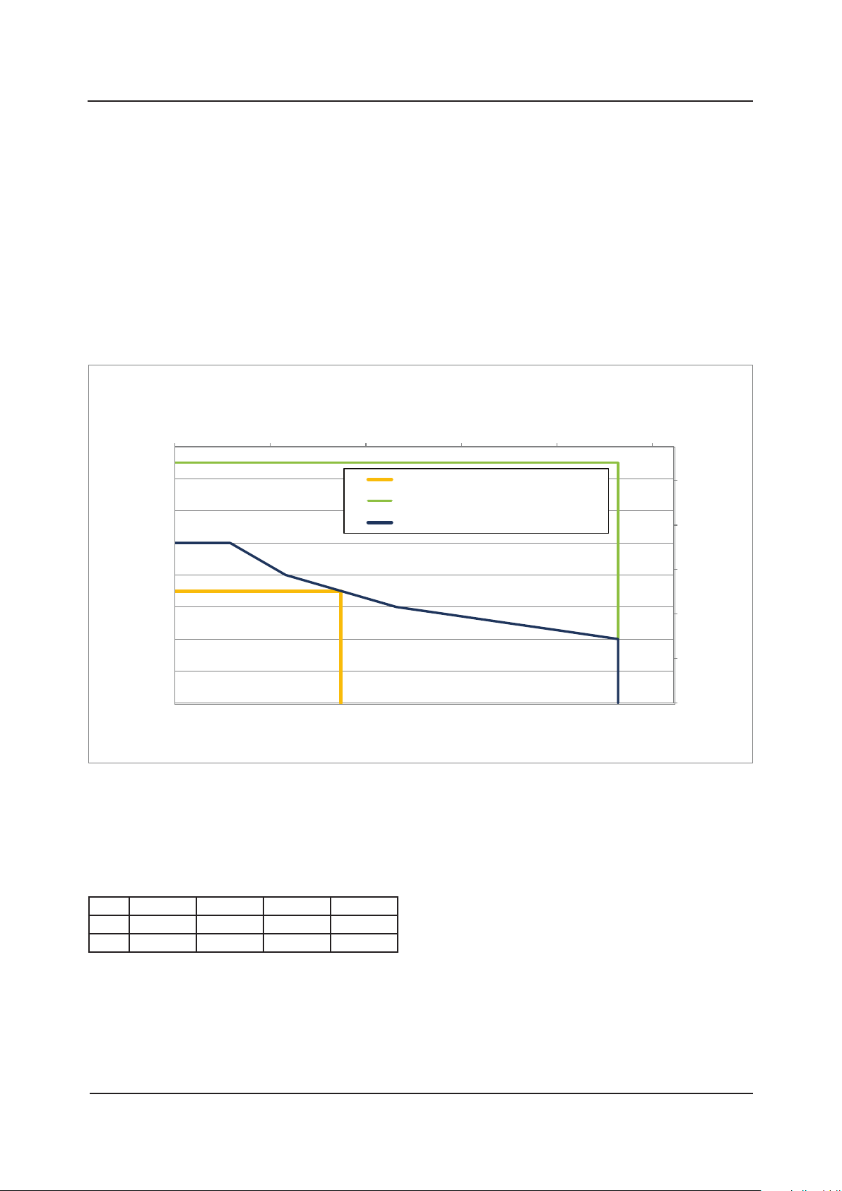
Temperature/pressure specification
PP with valve
SS with or w/o valve, with option /IB
PP without valve
APPROVALS IN EAEU AND CIS COUNTRIES
Eurasian Conformity (EAC)
RAGK with options /GR complies to applicable Technical
Regulations valid in EAEU countries Russia, Belarus,
Kazakhstan, Armenia and Kyrgyzstan.
• TR CU 004
• TR CU 020
Pattern Approval certicate of Measuring Instruments
RAGK has “Pattern Approval Certicate of Measuring
Instruments”
and is registered as a measuring instrument in Russia.
Option /QR: Primary verication approval with technical
passport
For export to other CIS countries please contact your
Yokogawa representative.
3
Fig.3: Temperature/pressure specication
Further temperature restrictions are applicable in case of
option /GM (limit switches), option /NBR and option /R1
and /R3.
Table 2: Kvs and Cvs value of the valves
Cone 13 to 21 22 to 41 42 to 47 52 to 57
Kvs 0.024 m3/h 0.06 m3/h 0.24 m3/h 1.125 m3/h
Cv
All Rights Reserved. Copyright © 2004, Rota Yokogawa
0.028 gpm 0.07 gpm 0.28 gpm 1.316 gpm
s
GS 01R01B07-00E-E 15th edition, April 01, 2020-00
Page 4

4
LIMIT SWITCH, option /GR1 to /GR8 for RAGK41
With limit switches no protection cover for the tube is
provided.
Floats:
• Mumetal (MU) or PVDF (PD)
• Qmin > 0.004 l/h water or 0.3 l/h air
(Qmin > 0.001 gph water or 0.076 gph air)
Type:
Bistable inductive ring sensor to be used with the
appropriate power supply
Power supply: 4.5 V to 15 V DC
Current levels: acc. DIN EN 60947-5-6
Temperature range: -20 °C to +65 °C
(-4 °F to 149 °F)
Protection: IP 67
Electrical connection: 2 x 0.14 mm²,
with shield 0.4 mm²,
2 m (78") long
EMC compliance:
According to EN 60947-5-2 table 8 (for use in
industrial locations). Based on EMC compliance the
limit switch is marked with CE, EAC and RCM mark.
LVD compliance:
EN 60010-1 and EN 60010-2-030 for option /GM
Hazardous area use (option /KS1, /ES1):
Temperature range: -20 °C to +60 °C
(-4 °F to 140 °F)
Certicate No.:
• PTB 03 ATEX 2111 (/KS1)
• IECEx PTB13.0023 (/ES1)
Protection: Ex ia IIC T6 Gb
Safety relevant input Parameter:
Ui = 12 V, Ii = 22 mA , Pi = 66 mW,
Li = 20 mH, Ci = 200 nF
CE-marking: II 2 G
Markings on the label of the limit switch:
CE, EAC, China RoHS, RCM, Morocco
LIMIT SWITCH, option /GM1 to /GM5 for RAGK42
Floats: PP with insertion M
Type: bistable reed contact
Max. switching voltage: 230 V
Max. switching current: 0.6 A
Max. switching capacity: 12 VA or 12 W
Temperature range: -10 °C to +70 °C
(-14 °F to 158 °F)
Protection: IP 65
Internal capacity: 0 nF
Internal inductance: 0 mH
Connection cable: LIYY 2 x 0.34 mm²; length: 1 m
Housing: Polystyrene
Hazardous area use
Intrinsic safe acc. IEC 60079-11 chapter 5.7,
EN 60079-11 chapter 5.7 and ANSI/ISA 60079-11
chapter 5.7 as “Simple Apparatus” and therefore
does not require a specic hazardous area approval
by a notied body.
Temperature range:
-10 °C to +70 °C (14 °F to 158 °F)
Installation area (ATEX, IECEx):
IIC T6 2G
Installation area (NEC):
Class I, Zone 1, Groups A, B, C, D, T6
Safety relevant input Parameter:
Ui = 15 V; Ii = 50 mA; Pi = 187 mW
Li ≈ 0 mH; Ci ≈ 0 nF
Markings on the label of the limit switch:
CE, RCM, Morocco
POWER SUPPLY FOR LIMIT SWITCHES,
option /WA
and /WB
Type:
Acc. to
•
•
•
Power supply:
• 230 V AC ± 10 %, 45 to 65 Hz
• 115 V AC ± 10 %, 45 to 65 Hz
• 24 V DC ± 25 %
Relay output:
1 or 2 potential-free change over contact(s)
Switching capacity:
Max. 250 V AC, max. 2 A
EN 60947-5-6
KFA5-SR2-Ex*-W (115 V AC);
KFA6-SR2-Ex*-W (230 V AC);
KFD2-SR2-Ex*-W (24 V DC); * = 1 or 2
* = 1 or 2
* = 1 or 2
POWER SUPPLY FOR INTRINSICALLY SAFE LIMIT
SWITCHES,
Technical data same as above.
Type:
Acc. to
•
•
•
Approvals:
•
•
•
•
• EAC: RU С-DE.EX01.В.00102/19
• NEPSI: GYJ17.1283
•
•
•
•
• NEPSI: GYJ17.1283
•
•
•
•
• EAC: RU С-DE.EX01.В.00102/19
• NEPSI: GYJ17.1284
Control circuit (ATEX):
[
Ex ia] IIC; group II; category (1)GD
Entity parameter:
See certicates
option /WA and /WB
EN 60947-5-6
KFA5-SR2-Ex*-W (115 V AC);
KFA6-SR2-Ex*-W (230 V AC);
KFD2-SR2-Ex*-W (24 V DC); * = 1 or 2
KFA5-SR2-Ex*-W
ATEX: PTB 00 ATEX 2081
FM: ID 3011578
IECEx: PTB11.0031
KFA6-SR2-Ex*-W
ATEX: PTB 00 ATEX 2081
FM: ID 3011578
IECEx: PTB11.0031
• EAC: RU С-DE.EX01.В.00102/19
KFD2-SR2-Ex*-W
ATEX: PTB 00 ATEX 2080
FM: ID 3011578
IECEx: PTB11.0034
:
:
:
* = 1 or 2
* = 1 or 2
GS 01R01B07-00E-E 15th edition, April 01, 2020-00
All Rights Reserved. Copyright © 2004, Rota Yokogawa
Page 5

FLOW CONTROLLER, option /R1 and /R3 for
0123
05
RAGK41
Flow regulator for constant ow in case of variations in
process pressure.
These are no valves to reduce the pressure.
• Flow Controller /R1 for liquids and gases
The regulator keeps the ow rate constant in case of
a variable inlet pressure and constant back pressure.
For gases the process conditions are the back
conditions. The inlet pressure should be minimum
400 mbar larger than the back pressure (see Fig.3).
• Flow Controller /R3 for gases with uctuations of
the back pressure and constant inlet pressure.
The process conditions are the inlet conditions.
The inlet pressure should be minimum 400 mbar
larger than the back pressure.
Max. liquid ow: 100 l/h (26.4 gph)
Max. gas ow: 3250 l/h (858.56 gph)
Max. pressure: 25 bar (362.6 psi)
Temperature range: -20 °C to +80 °C
(-4 °F to 176 °F)
Table 3: Material of the controllers
Housing Diaphragm Springs
/R1 or /R3 SS PTFE SS
1000
100
Flow in l/h, air at 20 °C, backpressure 1 bar
5
Control characteristic for /R1
flow 6
flow 5
flow 4
flow 3
flow 2
flow 1
10
Prepressure in barg
Control characteristic for /R1
1000
flow 6
flow 5
flow 4
100
10
Flow in gph, air at 68 °F, backpressure 68 psi
1
01020304
Prepressure in psi
Fig. 4 Control characteristic for /R1
The above curves show the control characteristic of the
inlet ow regulator /R1 with air for 6 different owrates,
each with xed valve position, back pressure 1 bar (14.5 psi)
(atmosphere conditions).
For the smallest owrate the regulation works best from
0.4 bar (5.8 psi) to 3 bar (43.5 psi) (or more) inlet pressure
change, for the largest owrate from 0.9 bar (13 psi) to
3 bar (43.5 psi) (or more).
flow 3
flow 2
flow 1
0
All Rights Reserved. Copyright © 2004, Rota Yokogawa
GS 01R01B07-00E-E 15th edition, April 01, 2020-00
Page 6

6
MODEL SPECIFICATIONS
Model Suffix code Description Restrictions
RAGK41 For K- and M-tubes
RAGK42 For M3-tubes
Process
connections
Material process
connections and
heads
Val ve NNN Without valve
Tube length -K 75 mm (2.95")
Tube diameter 6 10 mm (0.39") *)
Tube cone combination XX *)
Fluid scale G Fluid specication sticker scale on tube,
Float material -AL Float aluminum *)
Float diameter A 1.6 mm (0.06") *)
Flow mark L RAGK41, liquid *)
Float insertion N Standard
*)To be determined with the FlowCongurator
-T0 RAGK41: Female thread, ¼" NPT
RAGK42: Female thread, 3/8" NPT
-R0 RAGK41: Female thread, ¼" Rp
RAGK42: Female thread, 3/8" Rp
PP-PP Polypropylene head
SS-SS Stainless steel head
SV1 RAGK41, inlet valve, silver seat
SV2 RAGK41, outlet valve, silver seat
GV1 RAGK42, inlet valve, PTFE seat
GV2 RAGK42, outlet valve, PTFE seat
-M 150 mm (5.91")
7 17 mm (0.67") *)
3 28 mm (1.10") *)
recommended
A Fluid specication attached scale, blank
tube
N mm scale, sticker scale on tube Tmax = 100 °C (212 °F)
D Dual scale: G and A
F Dual scale: N and A
-GL Ball glass, black For gasses only *)
-KR Sintered oat Al2O3, red *)
-MU Float mumetal *)
-PD Float PVDF, milky white *)
-PP Float PP, light grey *)
-SR Ball SS For liquids only *)
-SS Float SS *)
-TT Float titan *)
B 3.2 mm (0.13") *)
C 6.3 mm (0.25") *)
D 9.5 mm (0.37") *)
3 15.7 mm (0.62") *)
G RAGK41, gas *)
2 RAGK42, liquid *)
3 RAGK42, liquid *)
6 RAGK42, gas *)
7 RAGK42, gas *)
M Float with magnet insertion
not with PP-PP
Tmax = 100 °C (212 °F)
Not with /GR or /GM
Not with /GRor /GM, Tmax =
100 °C (212 °F)
Not with /GRor /GM, Tmax =
100 °C (212 °F)
Mandatory for option /GM
GS 01R01B07-00E-E 15th edition, April 01, 2020-00
All Rights Reserved. Copyright © 2004, Rota Yokogawa
Page 7

OPTIONS
Options Option code Description Restrictions
Marking
Process
adapters as
added part
Limit switches
Hazardous area
app.
Scale /IB Scale imprinted on the tube and burned in Not for scale A, T max = 130 °C (266 °F)
Tests and
certicates
O-Rings
Alternative oat
stop
Accessories
Controller
Country specic
delivery
Country specic
application
Power supply
Special order /Z Customer specic design, must be specied separately. If /Z is selected, several suffix of Model Code can be changed to Z.
/B1
/BG Customer specic notes
/C01 Cutting ring in SS for 6 mm outer diameter tubes Only for RAGK41-T0
/C02 Cutting ring in SS for 8 mm outer diameter tubes Only for RAGK41-T0
/C03 Cutting ring in SS for 10 mm outer diameter tubes Only for RAGK41-T0 or RAGK42-T0
/C04 Cutting ring in SS for 12 mm outer diameter tubes Only for RAGK41-T0 or RAGK42-T0
/P01 Nozzle in SS, for exible hoses inner diameter 6 mm Only for RAGK41-R0
/P02 Nozzle in SS, for exible hoses inner diameter 8 mm Only for RAGK41-R0
/P03 Nozzle in SS, for exible hoses inner diameter 10 mm Only for RAGK42-R0
/W01 Swagelok® in SS for 6 mm outer diameter tubes Only for RAGK41-T0
/W02 Swagelok® in SS for 8 mm outer diameter tubes Only for RAGK41-T0
/W03 Swagelok® in SS for 10 mm outer diameter tubes Only for RAGK41-T0
/W04 Swagelok® in SS for 12 mm outer diameter tubes Only for RAGK41-T0
/GM1 Magnetic Min-contact Only for RAGK42, insertion code M
/GM2 Magnetic Max-contact Only for RAGK42, insertion code M
/GM3 Magnetic Min-Max-contact Only for RAGK42, insertion code M
/GM4 Magnetic Min-Min-contact Only for RAGK42, insertion code M
/GM5 Magnetic Max-Max-contact Only for RAGK42, insertion code M
/GR1 Bistable inductive ring sensor
/GR2 Bistable inductive ring sensor
/GR3 Bistable inductive ring sensor
/GR4 Bistable inductive ring sensor
/GR5 2 bistable inductive ring sensors (2 x /GR1)
/GR6 2 bistable inductive ring sensors (2 x /GR2)
/GR7 2 bistable inductive ring sensors (2 x /GR3)
/GR8 2 bistable inductive ring sensors (2 x /GR4)
/KS1 ATEX intrinsically safe “ia“ Only for /GR1 to /GR8
/ES1 IECEx intrinsically safe “ia“ Only for /GR1 to /GR8
/H1 Oil and fat free for wetted surface acc. to Yokogawa specication Not with /R1, /R3
/P2 Certicate of compliance with the order acc. to EN 10204: 2004-2.1
/P3 As /P2 + Test report acc. to EN 10204: 2004-2.2
/PP Pressure test report for measuring system
/PT Flow table for recalculation to other uid Only for N and F scale, uid data must be provided
/NBR NBR O-rings for tube and valve (if ordered) Temperature range: -20 °C to 100 °C (-4 °F to 212 °F)
/KAL Kalrez O-rings for tube and valve (if ordered) Only for RAGK41
/S1 Float spring stops made of SS 1.4571
/QP Means for panel mounting Only for RAGK41
/QB With tapped holes in the connecting heads for mounting Only for RAGK41
/QF Foot stand Only for RAGK41
/QC Colored caps for valve knob (red, blue, yellow, green) Only with valve, only for RAGK41
/R1 Flow regulator for alternating pre-pressure
/R3 Flow regulator for alternating back-pressure
/KC KC-mark for Korea
/CN China RoHS mark
/VR Pattern Approval for Russia
/QR Primary Vercation for Russia Only with /VR. Not for cones 13 to 24
/W1A KFA5-SR2-Ex1.W, 115 V AC, 1 channel For /GM1, GM2 and /GR1 to GR4
/W1B KFA5-SR2-Ex2.W, 115 V AC, 2 channels For /GM3 to /GM5 and /GR5 to GR8
/W2A KFA6-SR2-Ex1.W, 230 V AC, 1 channel For /GM1, GM2 and /GR1 to GR4
/W2B KFA6-SR2-Ex2.W, 230 V AC, 2 channels For /GM3 to /GM5 and /GR5 to GR8
/W4A KFD2-SR2-Ex1.W, 24 V DC, 1 channel For /GM1, GM2 and /GR1 to GR4
/W4B KFD2-SR2-Ex2.W, 24 V DC, 2 channels For /GM3 to /GM5 and /GR5 to GR8
By use of the FlowCongurator www.FlowCongurator.com restrictions are automatically taken into account.
Tag plate(SS) fastened with wire, plate: 12 x 40 mm; marking
must be provided by the customer
max. 45 characters
Only for oat MU AN
Only for oat PD BN or MU BN
Only for oat PD CN
Only for oat MU CN, MU DN, PD DN
Only for oat MU AN, not for K-tube
Only for oat PD BN or MU BN, not for K-tube
Only for oat PD CN, not for K-tube
Only for oat MU CN, MU DN, PD DN, not for
K-tube
Only for RAGK41, only with SS-head, only with
inlet valve
Only for RAGK41, only with SS-head, only with
outlet valve, only for gasses
Only with option /GMor /GR
7
All Rights Reserved. Copyright © 2004, Rota Yokogawa
GS 01R01B07-00E-E 15th edition, April 01, 2020-00
Page 8

8
A
B
B
A
Process connection -T0 or -R0 approx. 135mm (5.3")
Process connection
as add. part
Process connection
as add. part
B
A
Process connection -T0 or -R0 approx. 135mm (5.3")
A
B
DIMENSIONS AND WEIGHTS
Fig. 5 RAGK41 with valve
Fig. 6 RAGK42 with valve
Fig. 7 Version with inlet valve and inlet ow controller option /R1
Fig. 8 Version with outlet valve and outlet ow controller option /R3
GS 01R01B07-00E-E 15th edition, April 01, 2020-00
All Rights Reserved. Copyright © 2004, Rota Yokogawa
Page 9

Table 4: Weights and dimensions
E
A
A
L
t = 0.5 mm
to 10 mm
view A
Dimensions in mm (inch) Weight in g (lbs)
Measuring
tube
K6; K7 111 (4.37) 90 (3.54) 150 (0.33) 340 (0.75) 1060 (2.33)
M6; M7 186 (7.32) 165 (6.5) 230 (0.51) 500 (1.1) 1220 (2.89)
M3 208 (8.19) 175 (6.89) 540 (1.19) 1160 (2.56) ---
A B w/o controller PP w/o controller SS with controller SS
I
F
9
H
G
Fig. 9 Head dimensions (with or w/o valve) with tapped holes for option /QB
Table 5: Dimensions of heads
Model Dimensions in mm (inch)
E F G H I
RAGK41 with K6/K7/ M6/ M7
RAGK42 with M3
29 (1.14) 12,5 (0.49) 25 (0.98) 19 (0.75) 33 (1.3) 3 (M3 screw)
42 (1.65) 20 (0.79) 40 (0.157) 20 (0.79) 42 (1.69) 5 (M5 screw)
Drill hole
diameter in
mm
Table 6: Slot dimensions in the panel
Model Dimensions in mm (inch)
A L
RAGK41 with K6/K7
RAGK41 with M6/M7
26 (1.02) 115 (4.53)
26 (1.02) 190 (7.45)
Fig. 10 Option /QP, means for panel mounting
All Rights Reserved. Copyright © 2004, Rota Yokogawa
GS 01R01B07-00E-E 15th edition, April 01, 2020-00
Page 10

10
YOKOGAWA ELECTRIC CORPORATION
YOKOGAWA CORPORATION OF AMERICA
YOKOGAWA AMERICA DO SUL LTDA.
YOKOGAWA EUROPE B. V.
Euroweg 2, 3825 HD Amersfoort,
THE NETHERLANDS
Phone : 31-88-4641000
Fax : 31-88-4641111
YOKOGAWA INDIA LTD.
Plot No.96, Electronic City Complex,
Hosur Road, Bangalore - 560 100,
INDIA
Phone : 91-80-4158-6000
Fax : 91-80-2852-1442
YOKOGAWA AUSTRALIA PTY. LTD.
Tower A, 112-118 Talavera Road,
Macquarie Park NSW 2113,
AUSTRALIA
Phone : 61-2-8870-1100
Fax : 61-2-8870-1111
YOKOGAWA MIDDLE EAST & AFRICA B.S.C.(C)
P.O. Box 10070, Manama, Building 577,
Road 2516, Busaiteen 225, Muharraq,
Kingdom of BAHRAIN
Phone : 973-17358100
Fax : 973-17336100
Headquarters
2-9-32, Nakacho, Musashino-shi,
Tokyo, 180-8750 JAPAN
Phone : 81-422-52-5555
Branch Sales Offices
Osaka, Nagoya, Hiroshima,
Kurashiki, Fukuoka, Kitakyusyu
Head Office
12530 West Airport Blvd, Sugar Land,
Texas 77478, USA
Phone : 1-281-340-3800
Fax : 1-281-340-3838
Georgia Office
2 Dart Road, Newnan, Georgia 30265, USA
Phone : 1-800-888-6400/ 1-770-253-7000
Fax : 1-770-254-0928
Praca Acapulco, 31 - Santo Amaro, Sáo Paulo/SP,
BRAZIL, CEP-04675-190
Phone : 55-11-5681-2400
Fax : 55-11-5681-4434
YOKOGAWA ELECTRIC CIS LTD.
Grokholskiy per 13 Building 2, 4th Floor 129090,
Moscow, RUSSIA
Phone : 7-495-737-7868
Fax : 7-495-737-7869
YOKOGAWA CHINA CO., LTD.
3F Tower D, No.568 West Tianshan RD.
Shanghai CHINA, 200335
Phone : 86-21-62396262
Fax : 86-21-62387866
YOKOGAWA ELECTRIC KOREA CO., LTD.
(Yokogawa B/D, Yangpyeong-dong 4-Ga),
21, Seonyu-ro 45-gil, Yeongdeungpo-gu,
Seoul, 150-866, KOREA
Phone : 82-2-2628-6000
Fax : 82-2-2628-6400
YOKOGAWA ENGINEERING ASIA PTE. LTD.
5 Bedok South Road, Singapore 469270,
SINGAPORE
Phone : 65-6241-9933
Fax : 65-6241-2606
ISO 9001
A
view A
158 (16.22“)
adjustable screw
134 (5.28“)
Fig. 11 Option /QF, foot stand, dimensions in mm (inch)
REGISTERED TRADEMARKS
Rotameter® is a trademark of Rota Yokogawa GmbH & Co. KG, a subsidiary of Yokogawa Electric Corporation, Japan.
In the United Kingdom Rotameter
Swagelok®: Registered trademark of Swagelok Company, Solon, Ohio, USA
GS 01R01B07-00E-E 15th edition, April 01, 2020-00
TM
is a trademark of Emerson Electric Co.
All Rights Reserved. Copyright © 2004, Rota Yokogawa
 Loading...