

Page 1

PX8000
Precision Power Scope
IM PX8000-02EN
6th Edition
Page 2

Thank you for purchasing the PX8000 Precision Power Scope (hereafter referred to as the PX8000).
This User’s Manual explains how to use the PX8000. To ensure correct use, please read this manual
thoroughly before beginning operation.
Keep this manual in a safe place for quick reference in the event a question arises. The following
manuals, including this one, are provided as manuals for the PX8000. Please read all manuals.
List of Manuals
The following four manuals, including this one, are provided as manuals for the PX8000. Read them
along with this manual.
Manual Title Manual No. Description
PX8000 Precision Power Scope
Features Guide
PX8000 Precision Power Scope
User’s Manual
PX8000 Precision Power Scope
Getting Started Guide
PX8000 Precision Power Scope
Communication Interface
User’s Manual
Model PX8000
Precision Power Scope
The “EN” and “Z1” in the manual numbers are the language codes.
The pdf data of all the manuals listed in the above table is in the supplied manual CD.
IM PX8000-01EN This manual explains all the PX8000 features other than
the communication interface features.
IM PX8000-02EN This manual. The manual explains how to operate the
PX8000.
IM PX8000-03EN Provided as a printed manual. This guide explains the
handling precautions, basic operations, and specifications
of the PX8000.
IM PX8000-17EN This manual explains the PX8000 communication interface
features and how to use them.
IMPX8000-92Z1 Document for China
Contact information of Yokogawa offices worldwide is provided on the following sheet.
Document No. Description
PIM 113-01Z2 List of worldwide contacts
Notes
• The contents of this manual are subject to change without prior notice as a result of continuing
improvements to the instrument’s performance and functionality. The figures given in this manual
may differ from those that actually appear on your screen.
• Every effort has been made in the preparation of this manual to ensure the accuracy of its
contents. However, should you have any questions or find any errors, please contact your nearest
YOKOGAWA dealer.
• Copying or reproducing all or any part of the contents of this manual without the permission of
YOKOGAWA is strictly prohibited.
• The TCP/IP software of this product and the documents concerning it have been developed/created
by YOKOGAWA based on the BSD Networking Software, Release 1 that has been licensed from
the Regents of the University of California.
Trademarks
•
Microsoft, Internet Explorer, MS-DOS, Windows, Windows XP, and Windows Vista are either registered
trademarks or trademarks of Microsoft Corporation in the United States and/or other countries.
• Adobe is either registered trademark or trademark of Adobe Systems Incorporated.
• MATLAB is a registered trademark of The MathWorks, Incorporated in the United States.
• GIGAZoom ENGINE is a registered trademark of Yokogawa Electric Corporation.
• In this manual, the ® and TM symbols do not accompany their respective®registered trademark or
trademark names.
•
Other company and product names are registered trademarks or trademarks of their respective holders.
6th Edition: October 2017 (YMI)
All Rights Reserved, Copyright © 2014 Yokogawa Test & Measurement Corporation
IM PX8000-02EN
i
Page 3

Revisions
• January 2014 1st Edition
• January 2014 2nd Edition
• August 2014 3rd Edition
• December 2015 4th Edition
• June 2017 5th Edition
• October 2017 6th Edition
ii
IM PX8000-02EN
Page 4

Conventions Used in This Manual
Notes
The notes and cautions in this manual are categorized using the following symbols.
Improper handling or use can lead to injury to the user or damage to the
instrument. This symbol appears on the instrument to indicate that the user must
refer to the user’s manual for special instructions. The same symbol appears in
the corresponding place in the user’s manual to identify those instructions. In the
user’s manual, the symbol is used in conjunction with the word “WARNING” or
“CAUTION.”
WARNING
CAUTION
French
AVERTISSEMENT
ATTENTION
Calls attention to information that is important for the proper operation of the
Note
Calls attention to actions or conditions that could cause serious or fatal injury to
the user, and precautions that can be taken to prevent such occurrences.
Calls attentions to actions or conditions that could cause light injury to the user
or damage to the instrument or user’s data, and precautions that can be taken to
prevent such occurrences.
Attire l’attention sur des gestes ou des conditions susceptibles
de provoquer des blessures graves (voire mortelles), et sur les
précautions de sécurité pouvant prévenir de tels accidents.
Attire l’attention sur des gestes ou des conditions susceptibles de
provoquer des blessures légères ou d’endommager l’instrument ou les
données de l’utilisateur, et sur les précautions de sécurité susceptibles
de prévenir de tels accidents.
instrument.
Unit
k Denotes 1000. Example: 100 kHz (frequency)
K Denotes 1024. Example: 720 KB (file size)
IM PX8000-02EN
iii
Page 5
Key and Jog Shuttle Operations
H
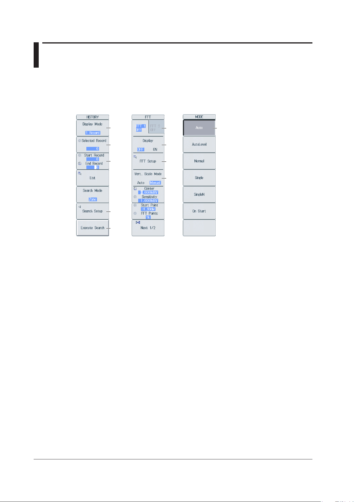
HISTORY menu FFT menu MODE menu
Key Operations
How to Use Setup Menus That Appear When Keys Are Pressed
The operation after you press a key varies depending on the key that you press.
A: Press the soft key to display a selection menu.
Press the soft key that corresponds to the appropriate setting.
B: Press the soft key to use the jog shuttle to configure this setting. Use the jog shuttle or the arrow
keys to set the value or select an item.
For a numeric setting, you can press NUM LOCK to use the ELEM 1 to P 4 keys to enter
numbers.
C: A related setup menu appears when you press the soft key.
D: Press the soft key to execute the specified feature.
E: Selects which item to configure when configuring a feature that consists of two items that
operate with different settings, such as the FFT1 and FFT2 features.
F: The selected setting switches each time you press the soft key.
G: A dialog box or the keyboard appears when you press the soft key.
Use the jog shuttle, SET key, and arrow keys to configure the settings in the dialog box or
operate the keyboard.
H: Press the soft key to apply the value assigned to the key.
A
B
B
C
D
E
F
G
F
iv
How to Display the Setup Menus That Are Written in Purple below the Keys
In the explanations in this manual, “SHIFT+key name (written in purple)” is used to indicate the
following operation.
Press
1.
Press the key that you want to display the setup menu of.
2.
SHIFT. The SHIFT key illuminates to indicate that the keys are shifted.
Now you can select the setup menus written in purple below the keys.
IM PX8000-02EN
Page 6

Key and Jog Shuttle Operations
+
ESC Key Operation
If you press
menu level above the current one. If you press ESC when the highest level menu is displayed, the
setup menu disappears.
ESC when a setup menu or available options are displayed, the screen returns to the
RESET Key Operation
If you press
is reset to its default value (depending on the operating state of the PX8000, the setting may not be
reset).
RESET when you are using the jog shuttle to set a value or select an item, the setting
SET Key Operations
The operation varies as indicated below depending on what you are setting.
• For a soft key menu that has two values that you use the jog shuttle to adjust
Press
• For a menu that has the jog shuttle + SET mark (
Press
SET to switch the value that the jog shuttle adjusts.
SET
) displayed on it
SET to confirm the selected item.
Arrow Key Operations
The operation varies as indicated below depending on what you are setting.
• When setting a value
Up and down
Left and right
• When selecting the item to set
You can use the up, down, left, and right arrow keys.
arrow keys: Increases and decreases the value
arrow keys: Changes which digit to set
IM PX8000-02EN
v
Page 7
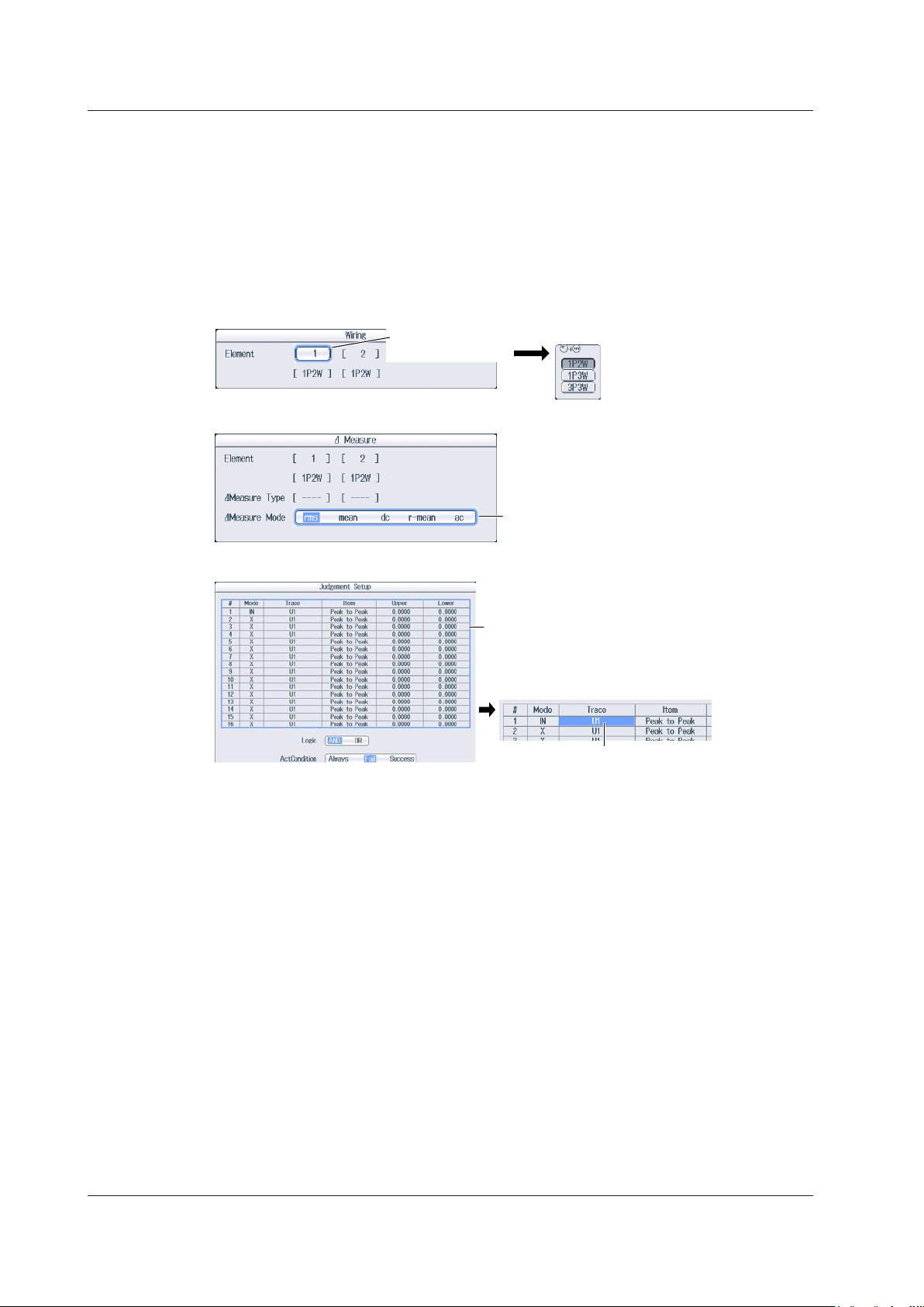
After selecting an item with the jog shuttle,
that you want to set.
Key and Jog Shuttle Operations
How to Enter Values in Setup Dialog Boxes
Use the keys to display the appropriate setup dialog box.
1.
Use the
2.
Press
3.
• A selection menu appears.
• A check box is selected or cleared.
• An item is selected.
• A table of settings is selected.
Displaying a Selection Menu and Selecting an Item
jog shuttle or the arrow keys to move the cursor to the setting that you want to set.
SET. The operation varies as indicated below depending on what you are setting.
Press SET to display
the selection menu.
How to Clear Setup Dialog Boxes
Press ESC to clear the setup dialog box from the screen.
press SET to confirm it.
Press SET to select rms, mean, dc,
r-mean, or ac.
Setting Items in a Table
After moving the cursor to the table, press SET to
select the setting in the table that you want to change.
To exit from the list, press ESC.
Press SET to select the item
vi
IM PX8000-02EN
Page 8

Entering Values and Strings
Use the keypad to enter the value.
Entering Values
Using Dedicated Knobs
You can use the following dedicated knobs to enter values directly.
• POSITION knob (vertical POSITION knob)
• RANGE knob
• TIME/DIV knob
• MAG knob (magnification knob)
• POSITION knob (zoom POSITION knob)
Using the Jog Shuttle
Select the appropriate item using the soft keys, and change the value using the jog shuttle and the
SET key or using the arrow keys. This manual sometimes describes this operation simply as “using
the jog shuttle.”
Using the Keypad
Press
NUM LOCK to illuminate the NUM LOCK key, and use the ELEM1 to P4 keys to enter a
value. After you enter the value, press ENTER to confirm it.
Note
Some items that you can set using the jog shuttle are reset to their default values when you press the RESET
key.
IM PX8000-02EN
vii
Page 9
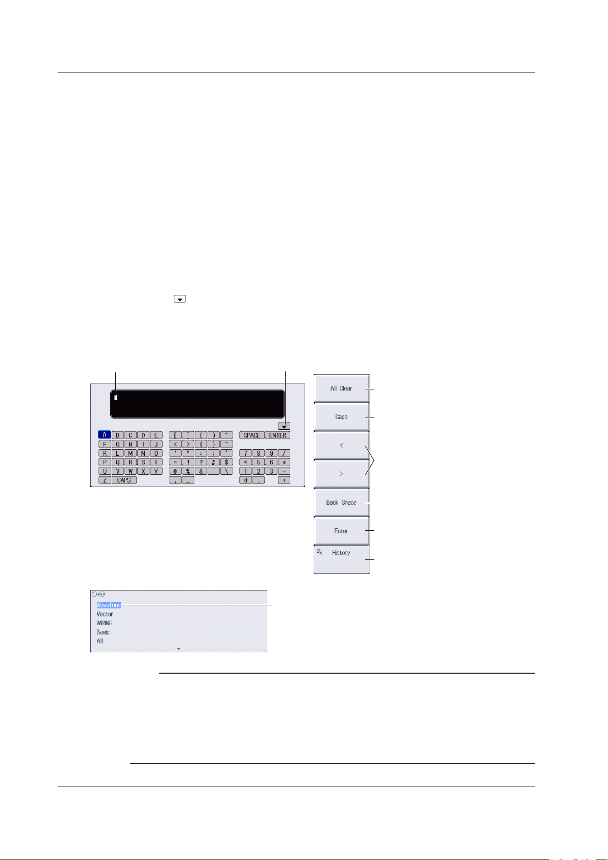
Character insertion position
Enter a character string from the history.
History (a list of character strings that yo
Entering Values and Strings
Entering Character Strings
Use the keyboard that appears on the screen to enter character strings such as file names and
comments. Use the jog shuttle, SET key, and arrow keys to operate the keyboard and enter a
character string.
How to Operate the Keyboard
After bringing up the keyboard, use the
1.
want to enter. You can also move the cursor using the up, down, left, and right arrow keys.
Press SET to enter the character.
2.
• If a character string has already been entered, use the
the position you want to insert characters into.
• To switch between uppercase and lowercase letters, press the
CAPS on the keyboard, and then press SET.
• To delete the previous character, press the
• To delete all the characters, press the
Repeat steps 1 and 2 to enter all of the characters in the string.
3.
Select on the keyboard or press the
entered previously. Use the jog shuttle to select a character string, and press SET to enter the selected
character string.
Press the
4.
The character string is confirmed, and the keyboard disappears.
jog shuttle to move the cursor to the character that you
arrow soft keys (< and >) to move the cursor to
Caps soft key or move the cursor to
Back Space soft key.
All Clear soft key.
History soft key to display a list of character strings that you have
Enter soft key, or move the cursor to ENTER on the keyboard, and press SET.
Deletes all characters
Switches between uppercase and
lowercase
Move the character insertion position
Deletes the previous character
Confirms the characters that
you have entered
Enter a character string from the history.
u have entered previously)
After selecting an item with the jog shuttle or up and
down arrow keys, press SET to confirm it.
Note
• @ cannot be entered consecutively.
• File names are not case-sensitive. Comments are case-sensitive. The following file names cannot be
used due to MS-DOS limitations:
AUX, CON, PRN, NUL, CLOCK, COM1 to COM9, and LPT1 to LPT9
For details on file name limitations, see the Features Guide, IM PX8000-01EN.
• When a character string is confirmed, it is stored in a list of previously entered strings. Up to 50 character
strings are stored. The new character string appears at the top of the list of previously entered strings.
viii
IM PX8000-02EN
Page 10

Contents
Conventions Used in This Manual ................................................................................................... iii
Key and Jog Shuttle Operations
Entering Values and Strings
Chapter 1 Fundamental Measurement Conditions
1.1 Configuring Wiring System Settings ................................................................................. 1-1
1.2 Configuring Power Measurement Element Settings ......................................................... 1-3
1.3 Setting the Motor Mode .................................................................................................... 1-4
Chapter 2 Vertical and Horizontal Control
2.1 Configuring Voltage Measurements ................................................................................. 2-1
2.2 Configuring Current Measurements ................................................................................. 2-4
2.3 Configuring Power Measurements ................................................................................... 2-8
2.4 Configuring Sensor Input Voltage Measurements .......................................................... 2-10
2.5 Configuring Rotating Speed Measurements .................................................................. 2-17
2.6 Configuring Torque Measurements ................................................................................ 2-23
2.7 Displaying the Menu for Configuring All Channels ......................................................... 2-29
2.8 Configuring the Horizontal Axis (Time axis) .................................................................... 2-31
Chapter 3 Triggering
3.1 Setting the Trigger Mode .................................................................................................. 3-1
3.2 Setting the Trigger Position and Trigger Delay ................................................................. 3-2
3.3 Setting the Trigger Hold Off .............................................................................................. 3-3
...................................................................................................... iv
............................................................................................................ vii
Simple trigger
3.4 Triggering on an Edge Trigger (Simple) ........................................................................... 3-4
3.5 Triggering on a Timer Trigger (Simple) ............................................................................. 3-5
3.6 Triggering on an External Trigger (Simple) ....................................................................... 3-6
3.7 Triggering on a Power Line Signal (Simple) ..................................................................... 3-7
Enhanced trigger
3.8 Triggering on an A -> B(N) Trigger (Enhanced) ................................................................ 3-8
3.9 Triggering on an A Delay B Trigger (Enhanced) ............................................................... 3-9
3.10 Triggering on an Edge On A Trigger (Enhanced) ........................................................... 3-10
3.11 Triggering on an OR or AND Trigger (Enhanced) ............................................................3-11
3.12 Triggering on a Period Trigger (Enhanced) .................................................................... 3-13
3.13 Triggering on a Pulse Width Trigger (Enhanced) ........................................................... 3-15
3.14 Triggering on a Wave Window Trigger (Enhanced) ........................................................ 3-17
Manual trigger
3.15 Triggering the PX8000 Manually (Manual Trigger) ......................................................... 3-18
Chapter 4 Waveform Acquisition
4.1 Setting Conditions for Waveform Acquisition .................................................................... 4-1
4.2 Starting and Stopping Waveform Acquisition ................................................................... 4-3
Chapter 5 Display Mode
5.1 Selecting the Display Mode .............................................................................................. 5-1
IM PX8000-02EN
ix
Page 11

Contents
Chapter 6 Numeric Data Display
6.1 Switching the Displayed Page .......................................................................................... 6-1
6.2 Changing the Displayed Items on the 4-, 8-, and 16-Value Displays ............................... 6-3
6.3 Changing the Displayed Items on the Matrix Display ....................................................... 6-5
6.4 Changing the All Items Display ......................................................................................... 6-7
6.5 Changing the Harmonics List Display (Option) ................................................................ 6-8
6.6 Setting the Custom Display ............................................................................................ 6-10
Chapter 7 Numeric Computation
7.1 Turning Numeric Measurement On and Off ..................................................................... 7-1
7.2 Setting the Calculation Period .......................................................................................... 7-2
7.3 Setting Numeric Data Averaging ...................................................................................... 7-3
7.4 Setting User-Defined Functions ....................................................................................... 7-4
7.5 Setting Apparent Power, Reactive Power, and Corrected Power Equations .................... 7-6
7.6 Setting the Phase Difference Display Format................................................................... 7-8
7.7 Setting Harmonic Measurement Conditions ..................................................................... 7-9
Chapter 8 Waveform Display
8.1 Setting the Waveform Display .......................................................................................... 8-1
8.2 Using the Snapshot and Clear Trace Features ................................................................ 8-3
Chapter 9 Bar Graph Display (Option)
9.1 Configuring the Bar Graph Display ................................................................................... 9-1
Chapter 10 Vector Display (Option)
10.1 Configuring the Vector Display ....................................................................................... 10-1
Chapter 11 X-Y Display
11.1 Displaying X-Y Waveforms ..............................................................................................11-1
Chapter 12 Zooming Waveforms
12.1 Zooming in on or out of Waveforms ............................................................................... 12-1
Chapter 13 Cursor Measurement
13.1 Measuring with Horizontal Cursors ................................................................................ 13-1
13.2 Measuring with Vertical Cursors ..................................................................................... 13-2
13.3 Measuring with Marker Cursors (Marker) ....................................................................... 13-3
13.4 Measuring with Angle Cursors (Degree) ........................................................................ 13-5
13.5 Measuring with Horizontal and Vertical Cursors (H & V) ................................................ 13-6
13.6 Measuring with Peak Cursors (Peak) ............................................................................. 13-7
Chapter 14 Automated Measurement of Waveform Parameters
14.1 Automatically Measuring Waveform Parameters ........................................................... 14-1
14.2 Performing Normal Statistical Processing ...................................................................... 14-4
14.3 Performing Cyclic Statistical Processing ........................................................................ 14-5
Chapter 15 Waveform Computation
15.1 Performing Addition, Subtraction, Multiplication, and Division ....................................... 15-1
15.2 Performing Binary Conversion ....................................................................................... 15-2
15.3 Shifting the Phase .......................................................................................................... 15-3
15.4 Displaying the Power Spectrum ..................................................................................... 15-4
15.5 Performing User-Defined Computations ........................................................................ 15-5
x
IM PX8000-02EN
Page 12

Chapter 16 FFT
16.1 Displaying FFT Waveforms ............................................................................................ 16-1
Chapter 17 GO/NO-GO Determination
17.1 Performing GO/NO-GO Determination with Waveform Zones ....................................... 17-1
17.2 Performing GO/NO-GO Determination with Waveform Parameters .............................. 17-4
Chapter 18 Action
18.1 Setting Actions ................................................................................................................ 18-1
Chapter 19 Searching Waveforms
19.1 Searching for Edges ....................................................................................................... 19-1
19.2 Searching for a Specific Time ......................................................................................... 19-3
Chapter 20 Displaying and Searching History Waveforms
20.1 Displaying Waveform History Waveforms ...................................................................... 20-1
20.2 Searching History Waveforms ........................................................................................ 20-3
Chapter 21 Printing and Saving Screen Captures
21.1 Loading Roll Paper Into the Built-In Printer (Optional) ................................................... 21-1
21.2 Printing on the Built-in Printer (Option) ........................................................................... 21-3
21.3 Saving Screen Captures to Files .................................................................................... 21-4
Contents
Chapter 22 Saving and Loading Data
22.1 Connecting Storage Media ............................................................................................. 22-1
22.2 Formatting Storage Media .............................................................................................. 22-4
22.3 Saving Waveform Data ................................................................................................... 22-6
22.4 Saving Numeric Data ....................................................................................................22-11
22.5 Saving Setup Data ....................................................................................................... 22-14
22.6 Saving Other Types of Data ......................................................................................... 22-15
22.7 Loading Waveform Data ............................................................................................... 22-19
22.8 Loading Setup Data ...................................................................................................... 22-20
22.9 Loading Other Types of Data........................................................................................ 22-21
22.10 Performing File Operations .......................................................................................... 22-22
Chapter 23 Ethernet Communication
23.1 Connecting the PX8000 to a Network ............................................................................ 23-1
23.2 Configuring TCP/IP Settings ........................................................................................... 23-3
23.3 Accessing the PX8000 from a PC (FTP Server) ............................................................ 23-4
23.4 Connecting to a Network Drive ....................................................................................... 23-5
23.5 Using SNTP to Set the Date and Time ........................................................................... 23-6
Chapter 24 Other Operations
24.1 Calibrating the PX8000 .................................................................................................. 24-1
24.2 Using the NULL Feature ................................................................................................. 24-2
24.3 Setting Time Synchronization (Option) ........................................................................... 24-3
24.4 Changing the Message, Menu, and USB Keyboard Languages .................................... 24-4
24.5 Adjusting the Backlight ................................................................................................... 24-5
24.6 Initializing the Settings .................................................................................................... 24-6
24.7 Configuring the Environment Settings ............................................................................ 24-7
24.8 Storing and Recalling Setup Data .................................................................................. 24-9
24.9 Locking the Keys .......................................................................................................... 24-10
IM PX8000-02EN
xi
Page 13

Contents
Chapter 25 Messages and Self-Test
25.1 Messages and Corrective Actions .................................................................................. 25-1
25.2 Carrying Out Self-Tests (Selftest) ................................................................................... 25-8
25.3 Viewing System Information (Overview)........................................................................25-11
Index
xii
IM PX8000-02EN
Page 14
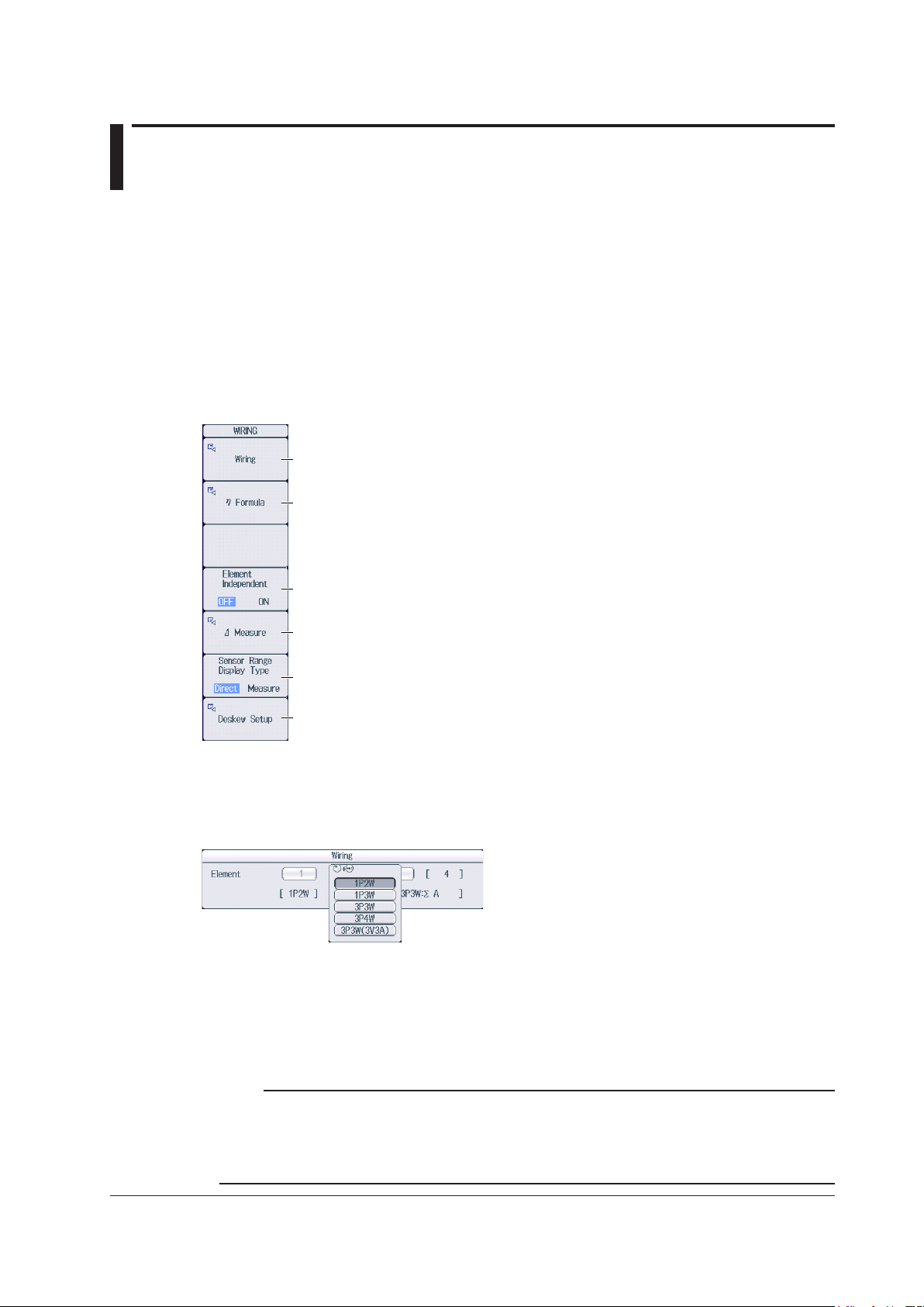
Set the wiring system (1P2W, 1P3W, 3P3W, 3P4W, 3P3W(3V3A)).
Chapter 1 Fundamental Measurement Conditions
1.1 Configuring Wiring System Settings
This section explains the following wiring system settings.
• Wiring system
• Efficiency equation
• Turning independent element configuration on and off
• Delta computation
• Display format of external current sensor range
• Deskewing (correcting the transfer time difference between input signals)
► Features Guide: “Wiring System Settings (WIRING)”
WIRING Menu
Press WIRING to display the following menu.
Set the wiring system.
Set the efficiency equation.
Turns independent element configuration on and off
Set delta computation.
Set the display format of external current sensor range
(Direct, Measure).
Set deskewing.
Setting the Wiring System
Press the Wiring soft key to display the following screen.
When you select an element, the wiring systems that you can select are displayed. Select the wiring system
from those displayed.
Wiring System Combination
• If you select 1P3W, 3P3W, 3P4W, or 3P3W(3V3A) for the wiring system, the wiring unit is set with the two
or three elements adjacent to the selected element whose element numbers are larger than the selected
element.
• On models that have four elements installed, up to two wiring units (ΣA and ΣB) are automatically set. The
wiring unit symbols ΣA and ΣB are attached to the element numbers in order, starting with the smallest
number.
IM PX8000-02EN
Note
• Because the wiring system with the largest element number is automatically determined according to
the settings of the wiring system with the smallest element number, the element with the largest element
number cannot be selected.
• You cannot set the wiring units for larger element numbers before the wiring units for smaller element
numbers.
1-1
Page 15
To add active powers and motor output and use them in efficiency equations, use Udef1 and Udef2.
Set the delta computation mode
(rms, mean, dc, r-mean, ac).
3P3W(3V3A) Delta>Star
Voltage (U) or current (I) of the installed
1.1 Configuring Wiring System Settings
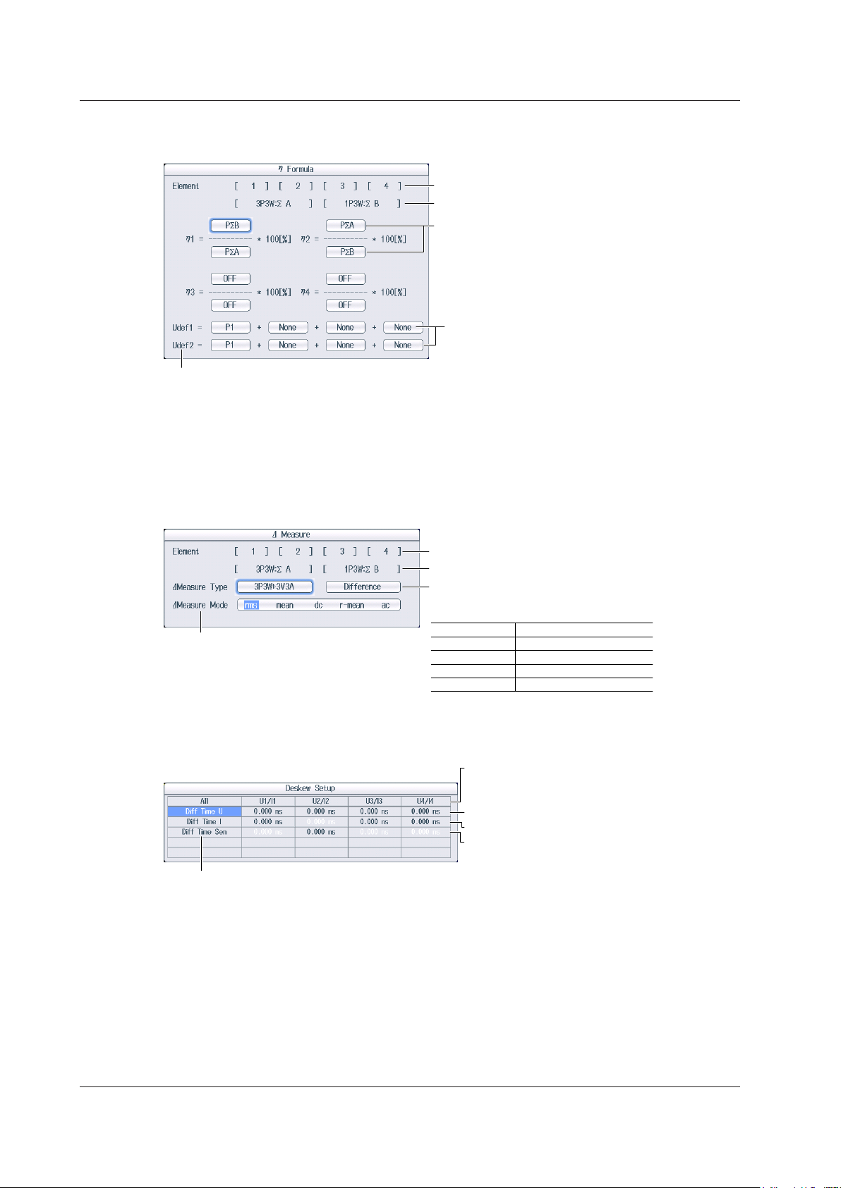
Setting the Efficiency Equation (η Formula)
Press the η Formula soft key to display the following screen.
1 P1 to P4 can be set within the range of the installed elements.
2 PΣA to PΣB can be set within the range of the wiring unit that is automatically determined by the installed
elements.
3 Pm2, Pm3, and Pm4 can be set when AUX modules are installed in slots 3, 5, and 7, respectively.
Setting Delta Computation (Δ Measure)
Press the Δ Measure soft key to display the following screen.
Installed elements
The set wiring systems
Set the denominator and numerator of the efficiency
equation to the active power and motor power
measurement functions.
1
, PΣA-PΣB2, Pm2-Pm43, Udef1, Udef2)
(P1-P4
You can set up to four equations: η1 to η4.
Define Udef1 and Udef2
1
(P1-P4
, PΣA-PΣB2, Pm2-Pm43).
Installed elements
The set wiring systems
Set the delta computation type.
The available options vary depending on
the set wiring systems.
Wiring System Delta Computation Type
1P3W Difference, 3P3W>3V3A
3P3W Difference, 3P3W>3V3A
3P4W Star>Delta
Setting Deskewing (Deskew Setup)
Press the Deskew Setup soft key to display the following screen.
elements
Manual deskewing
• Set the correction value for voltage signals.
To set or execute on all channels, set or
execute the items in the All row.
• Set the correction value for current signals.
• Set the correction value for external current
sensor signals.
1-2
IM PX8000-02EN
Page 16
1.2 Configuring Power Measurement Element
* When you are trying to read the current of the circuit under measurement directly by multiplying the
Settings
This section explains the following element settings.
• Line filter
• Frequency filter
• Turning the scaling feature on and off
• VT ratio
• CT ratio
• Power coefficient
• Synchronization source
► Features Guide: “Power Measurement Element Settings (ELEM1 to 4)”
Check that a voltage module and current module are installed in appropriate slots.
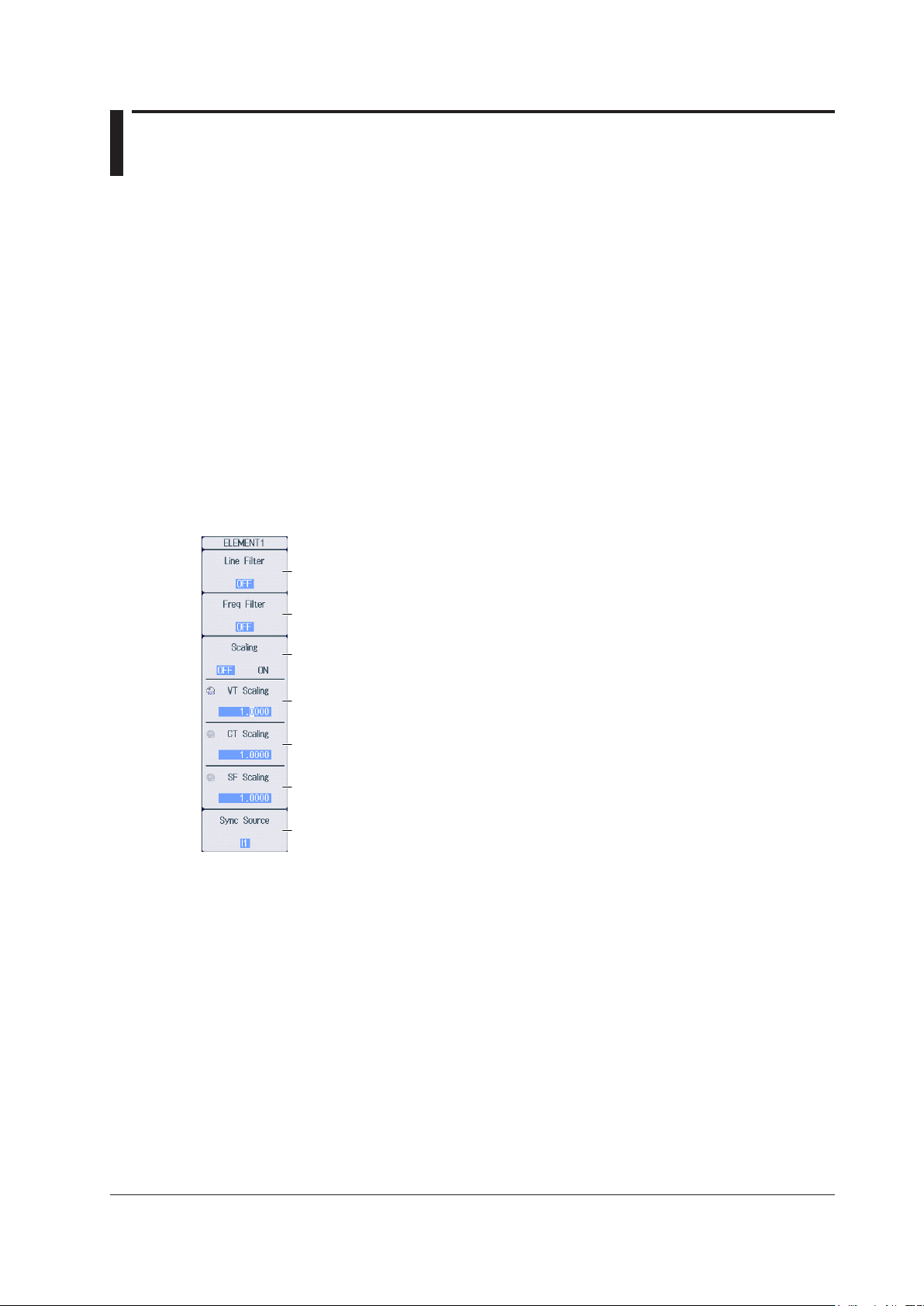
ELEM Menu
Of the ELEM1 to ELEM4 keys, press the key corresponding to the element in which the voltage and
current modules are installed. The following menu appears.
Set the line filter (OFF, 500Hz, 2kHz, 20kHz, 1MHz).
Set the frequency filter (OFF, 100Hz, 500Hz, 2kHz, 20kHz).
Turns the scaling feature on and off*
Set the VT ratio.
external current sensor output by the conversion ratio, if the scaling feature is set to ON, the CT ratio will
end up being multiplied on top of the result. To avoid the influence of the CT ratio, set the CT ratio to
1.0000.
Set the CT ratio.
Set the power coefficient.
Set the synchronization source (U1-U4, I1-I4, External, None).
IM PX8000-02EN
1-3
Page 17
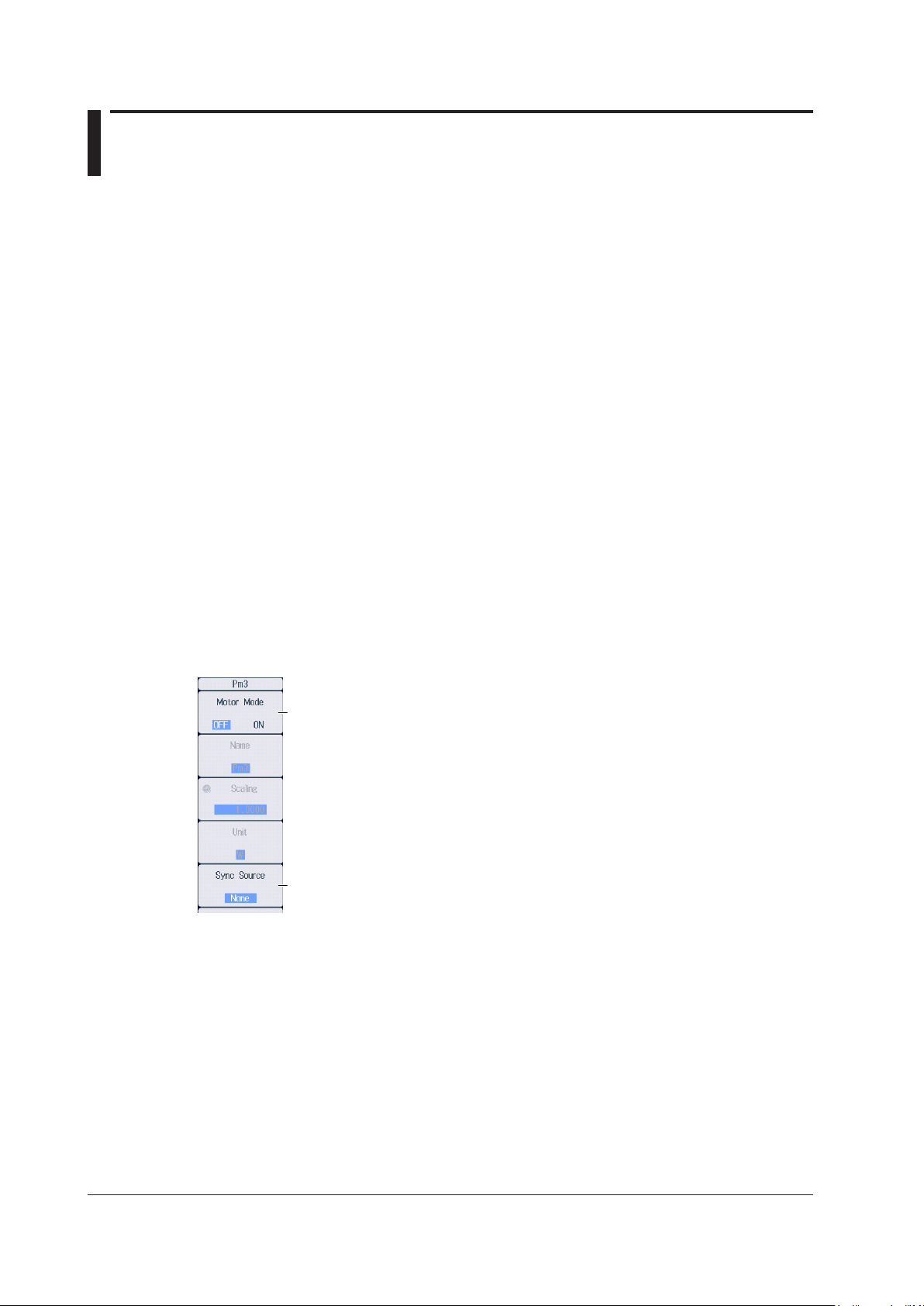
1.3 Setting the Motor Mode
When motor mode is off When motor mode is on
This section explains the following motor mode settings.
• Turning motor mode on and off
• Function name
• Scaling
• Unit
• Synchronization source
► Features Guide: “Turning Motor Mode On and Off (Motor Mode)”
“Synchronization Source (Sync Source), AUX Module”
Check that an AUX module is installed in slot 3, 5, or 7.
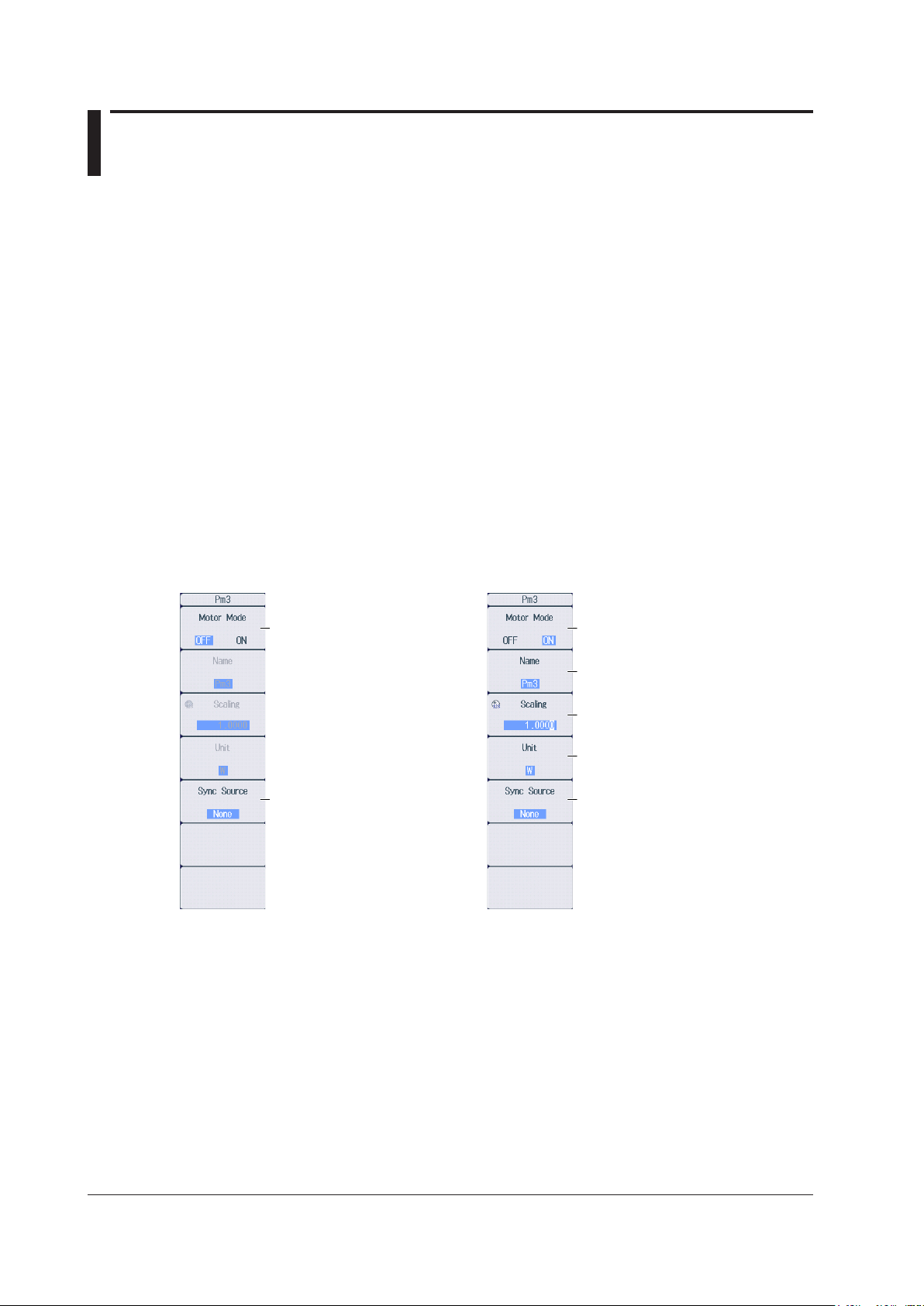
Pm Menu
Of the ELEM 2 to ELEM 4 keys, press the key corresponding to the slot in which the AUX module is
installed. The following menu appears.
“Function Name (Name)”
“Scaling (Scaling)”
“Unit (Unit)”
Set Motor Mode to OFF. Set Motor Mode to ON.
Set the synchronization source
(U1-U4, I1-I4, External, None).
Set the function name.
Set the scaling.
Set the unit.
Set the synchronization source
(U1-U4, I1-I4, External, None).
1-4
IM PX8000-02EN
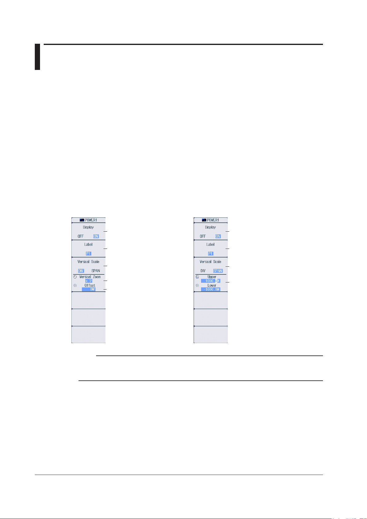
Page 18
Set the upper and lower limits of
When the zoom method is
When the zoom method is
set to DIV
Chapter 2 Vertical and Horizontal Control
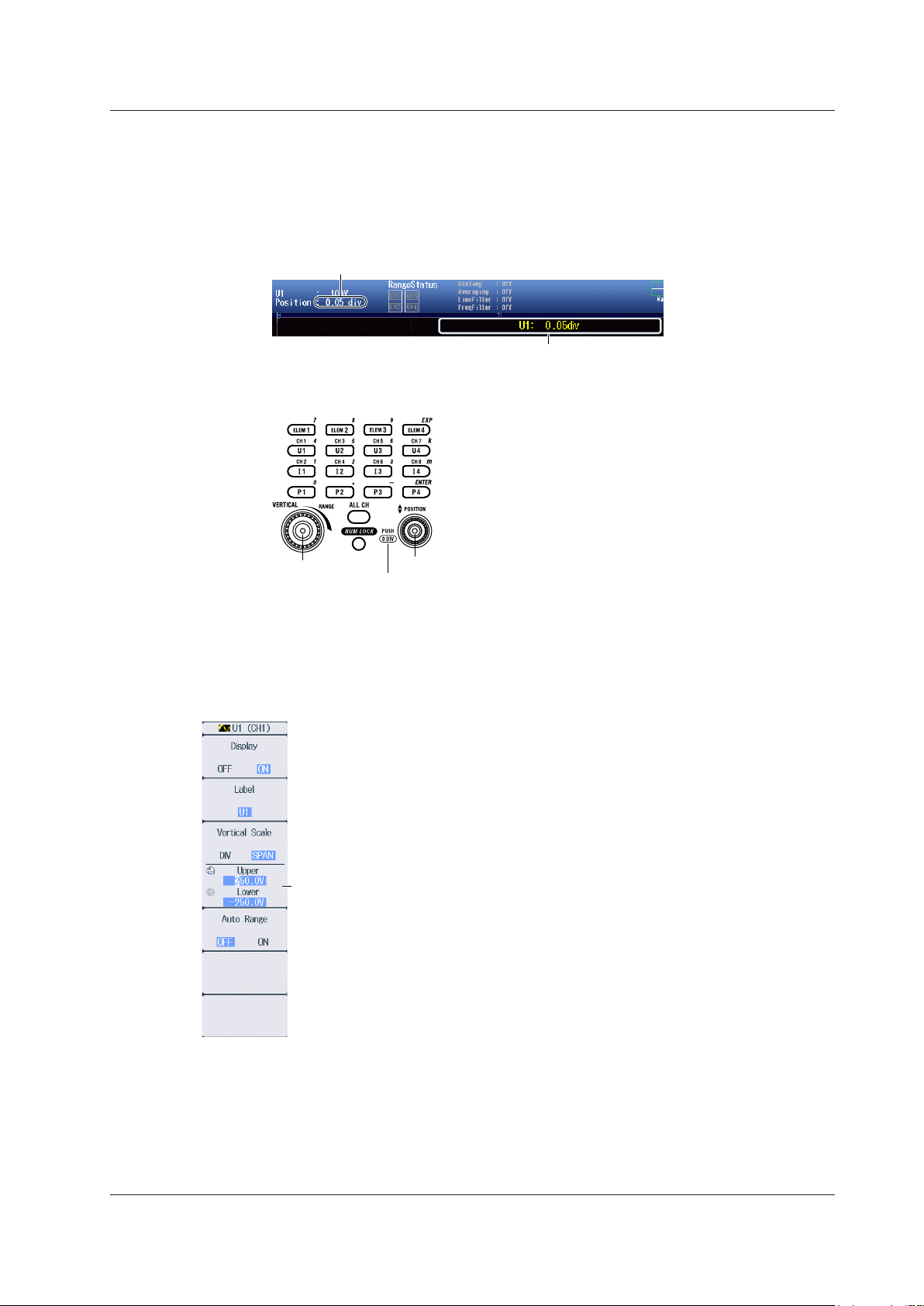
2.1 Configuring Voltage Measurements
This section explains the following settings for the vertical axis of voltage measurements.
• Waveform display on and off
• Display labels
• Zoom method
DIV: Magnification for zooming waveforms, offset
SPAN: Upper and lower display limits for zooming waveforms
• Auto range on and off
• Voltage measurement range (vertical scale)
• Voltage waveform vertical position
► Features Guide: “Voltage Measurement (U)”
Check that a voltage module and current module are installed in appropriate slots.
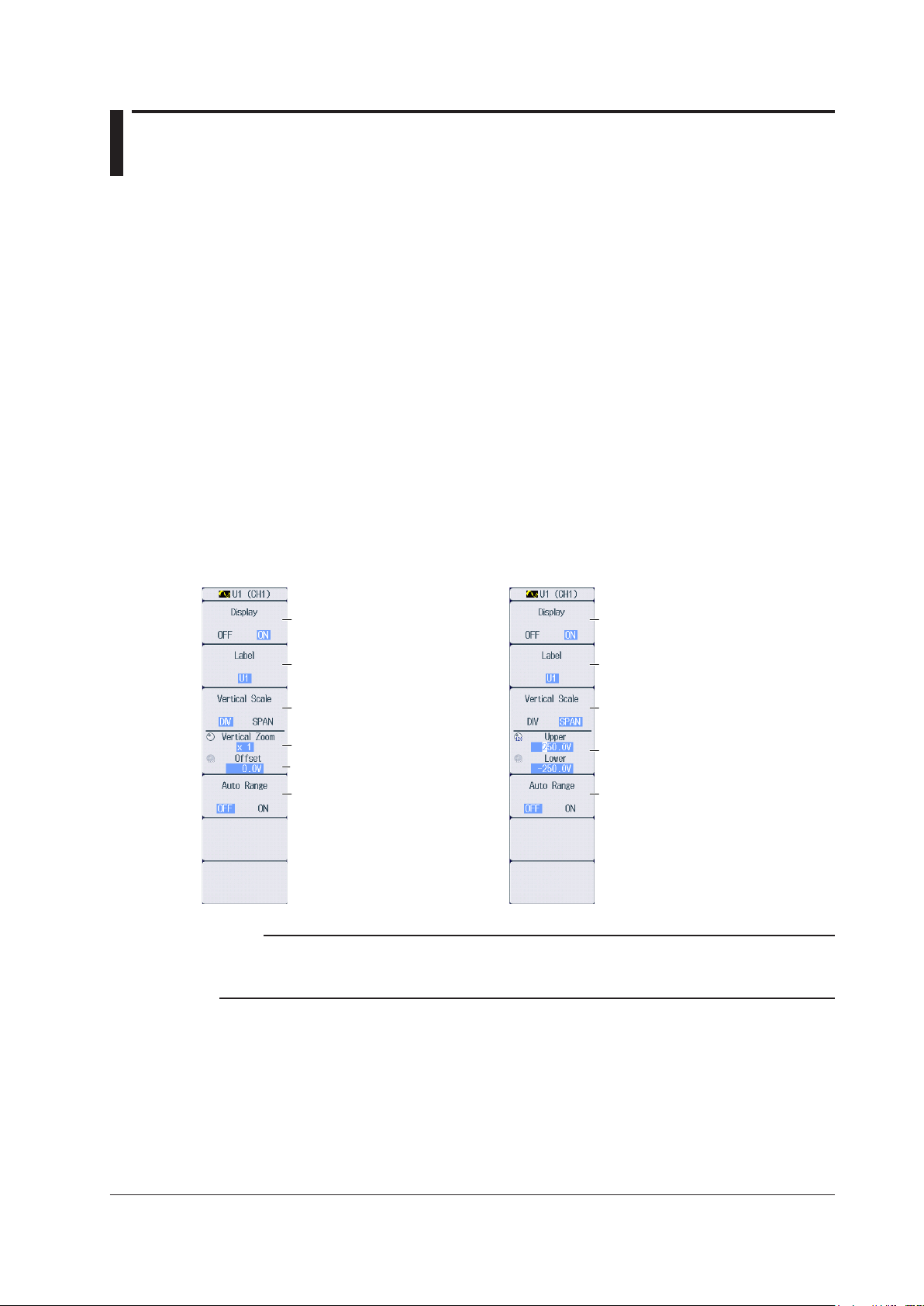
U Menu
Of the U1 to U4 keys, press the key corresponding to the element in which the module is installed.
The following menu appears.
set to SPAN
Turns the waveform display on
and off
Set the display label.
Set the zoom method to DIV.
Set the zoom magnification.
Set the offset.
Turns the auto range on and off
Turns the waveform display on
and off
Set the display label.
Set the zoom method to SPAN.
the display range.
Turns the auto range on and off
Note
The U key whose display setting is ON illuminates. If the U key is not illuminated, you can press it to turn on
the waveform display and the key. If the U key is illuminated, you can press it to turn off the waveform display
and the key.
IM PX8000-02EN
2-1
Page 19

Top row: Measurement range for the displayed waveforms
each element.
2.1 Configuring Voltage Measurements
Setting the Voltage Measurement Range
(Vertical Scale, RANGE Knob)
This section explains how to set a fixed range.
(If Auto Range in the U menu is set to ON, the measurement range changes depending on the
amplitude of the input signal.)
Turn the RANGE knob to set the voltage measurement range.
• Select from 1.5V, 3V, 6V, 10V, 15V, 30V, 60V, 100V, 150V, 300V, 600V, and 1000V.
• Auto Range in the U menu is set to OFF.
• If you turn the RANGE knob when waveform acquisition is stopped, two values are shown on the
measurement range screen. The upper value is the measurement range for the displayed waveforms.
The lower value is the measurement range that you have specified. The new range will be applied the
next time waveform acquisition is started.
• If you do not operate the RANGE knob for approximately 3 seconds, the measurement range that you
are setting with the knob will disappear from the screen.
Bottom row: Measurement range that you have specified
When the displayed waveform’s measurement range and the measurement range
that you have set are the same, only the bottom row is displayed.
Range status
Indicates the wiring units.
Display example
When the wiring system is 1P2W
Use the RANGE knob to display
the measurement range that is
currently being set.
Because the wiring unit is separate for each element,
set the measurement range of each element.
When the wiring system is 1P3W or 3P3W
Element 1 (CH1, CH2) and element 2 (CH3, CH4) are
grouped into a single wiring unit. Changing the
measurement range of one element will change that of
the other element to the same value.*
* If independent element configuration (see section 1.1)
to ON, you need to set the measurement range for
2-2
IM PX8000-02EN
Page 20
Setting the Voltage Waveform Vertical Position
Vertical position of the displayed waveform
This indicates that you can press the vertical POSITION knob
to set the vertical position to 0 div.
When the Zoom Method is Set to DIV (Vertical POSITION Knob)
Turn the vertical POSITION knob to set the waveform vertical position.
• Set in the range of –5.00 div to 5.00 div.
• If you do not operate the vertical POSITION knob for approximately 3 seconds, the vertical position that
you are setting with the knob will disappear from the screen.
Use the vertical POSITION knob to display the vertical
position that is currently being set.
• You can set the vertical position to 0 div by pressing the knob.
2.1 Configuring Voltage Measurements
RANGE knob
Vertical POSITION knob
When the Zoom Method is Set to SPAN (Upper and Lower Limits)
Using the Upper/Lower soft key and the jog shuttle, set the voltage at the top edge of the waveform
screen (upper limit) and the voltage at the bottom edge of the screen (lower limit) to set the waveform
vertical position.
Set the upper and lower limits of the display range.
IM PX8000-02EN
2-3
Page 21
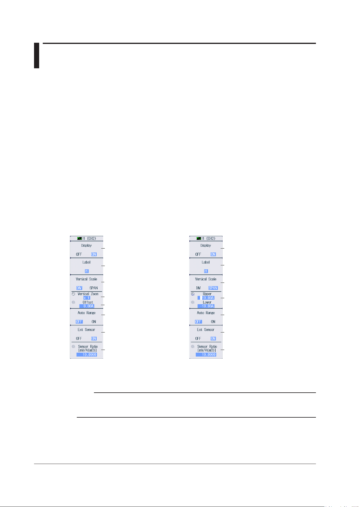
2.2 Configuring Current Measurements
Set the upper and lower limits of
When the zoom method is
When the zoom method is
set to DIV
This section explains the following settings for the vertical axis of current measurements.
• Waveform display on and off
• Display labels
• Zoom method
DIV: Magnification for zooming waveforms, offset
SPAN: Upper and lower display limits for zooming waveforms
• Auto range on and off
• Current measurement range (vertical scale)
Direct input, external current sensor (conversion ratio, input coupling)
• Current waveform vertical position
► Features Guide: “Current Measurement (I)”
Check that a voltage module and current module are installed in appropriate slots.
I Menu
Of the I1 to I4 keys, press the key corresponding to the element in which the module is installed.
The following menu appears.
set to SPAN
Turns the waveform display
on and off
Set the display label.
Set the zoom method to DIV.
Set the zoom magnification.
Set the offset.
Turns the auto range on and off
Turns the external current
sensor on and off*
Set the external current sensor
conversion ratio.*
Set this when the external current
sensor (Ext Sensor) is set to ON.
Turns the waveform display
on and off
Set the display label.
Set the zoom method to SPAN.
the display range.
Turns the auto range on and off
Turns the external current
sensor on and off*
Set the external current sensor
conversion ratio.*
Set this when the external current
sensor (Ext Sensor) is set to ON.
• In the case of a 760813 (current module), Ext Sensor and Sensor Ratio do not appear.
Note
The I key whose display setting is ON illuminates. If the I key is not illuminated, you can press it to turn on
the waveform display and the key. If the I key is illuminated, you can press it to turn off the waveform display
and the key.
2-4
IM PX8000-02EN
Page 22
Top row: Measurement range for the displayed waveforms
each element.
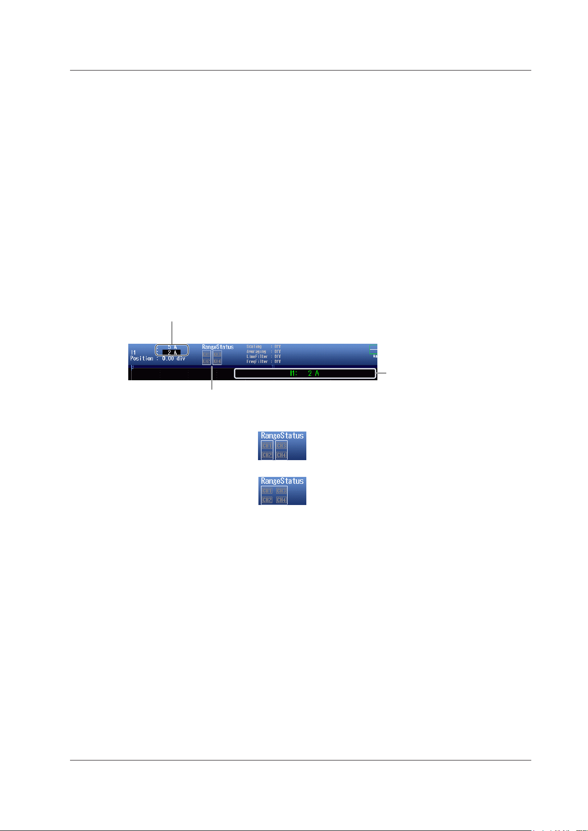
2.2 Configuring Current Measurements
Setting the Current Measurement Range
(Vertical Scale, RANGE Knob)
This section explains how to set a fixed range.
(If Auto Range in the I menu is set to ON, the measurement range changes depending on the
amplitude of the input signal.)
Direct Input Measurement Range Settings
(When Ext Sensor is set to OFF)
Turn the RANGE knob to set the current measurement range.
• Select from 10mA, 20mA, 50mA, 100mA, 200mA, 500mA, 1A, 2A, and 5A.
• Auto Range in the I menu is set to OFF.
• If you turn the RANGE knob when waveform acquisition is stopped, two values are shown on the
measurement range screen. The upper value is the measurement range for the displayed waveforms.
The lower value is the measurement range that you have specified. The new range will be applied the
next time waveform acquisition is started.
• If you do not operate the RANGE knob for approximately 3 seconds, the measurement range that you
are setting with the knob will disappear from the screen.
Bottom row: Measurement range that you have specified
When the displayed waveform’s measurement range and the measurement range
that you have set are the same, only the bottom row is displayed.
Range status
Indicates the wiring units.
Display example
When the wiring system is 1P2W
When the wiring system is 1P3W or 3P3W
Use the RANGE knob to display
the measurement range that is
currently being set.
Because the wiring unit is separate for each element,
set the measurement range of each element.
Element 1 (CH1, CH2) and element 2 (CH3, CH4) are
grouped into a single wiring unit. Changing the
measurement range of one element will change that of
the other element to the same value.*
* If independent element configuration (see section 1.1)
to ON, you need to set the measurement range for
IM PX8000-02EN
2-5
Page 23
Top row: Measurement range for the displayed waveforms
See page 2-5.
Top row: Measurement range for the displayed waveforms
See page 2-5.
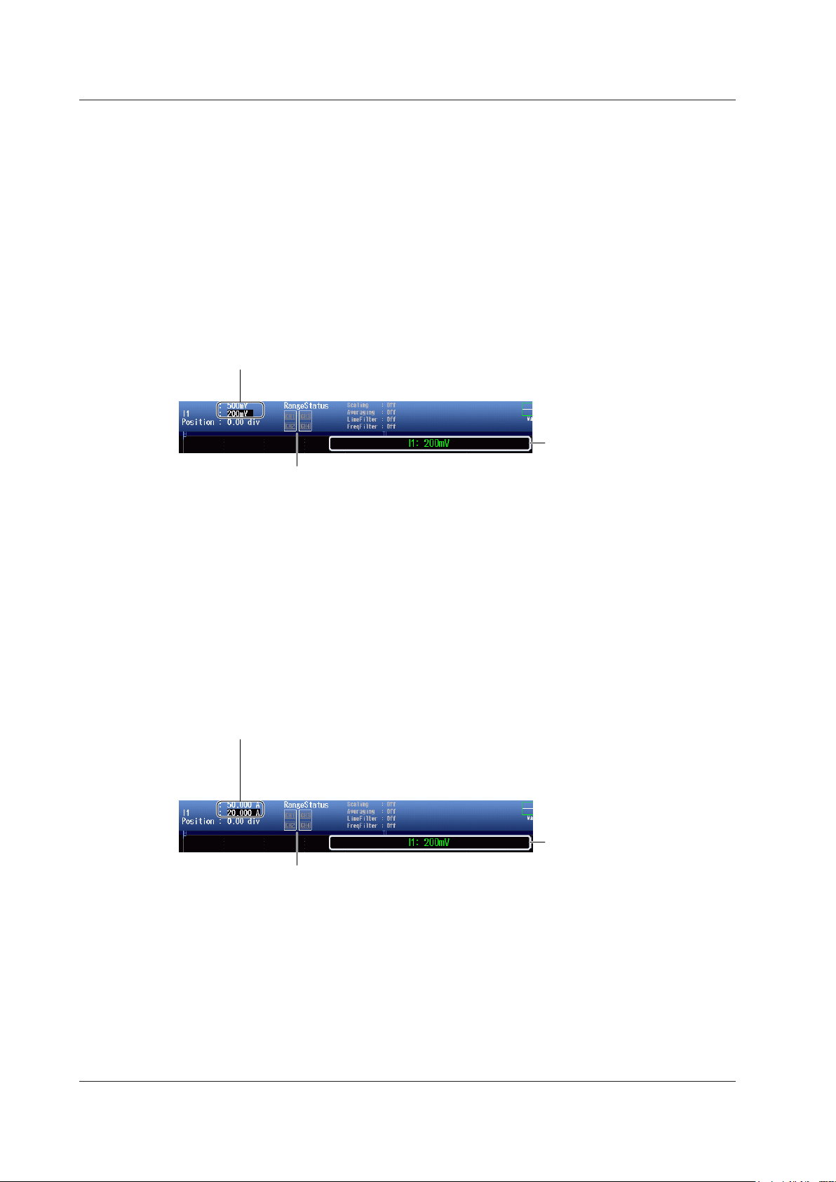
2.2 Configuring Current Measurements
External Current Sensor Input Measurement Range Settings
(When Ext Sensor is set to ON)
When the External Current Sensor Range Display Format (see section 1.1) Is Direct
Turn the RANGE knob to set the current measurement range.
• Select from 50mV, 100mV, 200mV, 500mV, 1V, 2V, 5V, and 10V.
• Auto Range in the I menu is set to OFF.
• If you turn the RANGE knob when waveform acquisition is stopped, two values are shown on the
measurement range screen. The upper value is the measurement range for the displayed waveforms.
The lower value is the measurement range that you have specified. The new range will be applied the
next time waveform acquisition is started.
• If you do not operate the RANGE knob for approximately 3 seconds, the measurement range that you
are setting with the knob will disappear from the screen.
Bottom row: Measurement range that you have specified
When the displayed waveform’s measurement range and the measurement range that you
have set are the same, only the bottom row is displayed.
Range status
Use the RANGE knob to display
the measurement range that is
currently being set.
When the External Current Sensor Range Display Format (see section 1.1) Is
Measure
Turn the RANGE knob to set the current measurement range.
• Select from 50mV, 100mV, 200mV, 500mV, 1V, 2V, 5V, and 10V.
• Auto Range in the I menu is set to OFF.
• If you turn the RANGE knob when waveform acquisition is stopped, two values are shown on the
measurement range screen. The upper value is the measurement range for the displayed waveforms.
The lower value is the measurement range that you have specified. The new range will be applied the
next time waveform acquisition is started.
• If you do not operate the RANGE knob for approximately 3 seconds, the measurement range that you
are setting with the knob will disappear from the screen.
Bottom row: Measurement range that you have specified
• The measurement range is set to the value that results when the measurement range set with
the RANGE knob is divided by the external current sensor conversion ratio (see page 2-4).
• When the displayed waveform’s measurement range and the measurement range that you
have set are the same, only the bottom row is displayed.
Use the RANGE knob to display
the measurement range that is
Range status
currently being set.
2-6
IM PX8000-02EN
Page 24

Setting the Current Waveform Vertical Position
Vertical position of the displayed waveform
This indicates that you can press the vertical POSITION knob
to set the vertical position to 0 div.
When the Zoom Method is Set to DIV (Vertical POSITION Knob)
Turn the vertical POSITION knob to set the waveform vertical position.
• Set in the range of –5.00 div to 5.00 div.
• If you do not operate the vertical POSITION knob for approximately 3 seconds, the vertical position that
you are setting with the knob will disappear from the screen.
Use the vertical POSITION knob to display the vertical
position that is currently being set.
• You can set the vertical position to 0 div by pressing the knob.
2.2 Configuring Current Measurements
RANGE knob
Vertical POSITION knob
When the Zoom Method is Set to SPAN (Upper and Lower Limits)
Using the Upper/Lower soft key and the jog shuttle, set the current at the top edge of the waveform
screen (upper limit) and the current at the bottom edge of the screen (lower limit) to set the waveform
vertical position.
Set the upper and lower limits of the display range.
IM PX8000-02EN
2-7
Page 25
2.3 Configuring Power Measurements
Set the upper and lower limits of
When the zoom method is
When the zoom method is
set to DIV
This section explains the following settings for the vertical axis of power measurements.
• Waveform display on and off
• Display labels
• Zoom method
DIV: Magnification for zooming waveforms, offset
SPAN: Upper and lower display limits for zooming waveforms
• Power waveform vertical position
► Features Guide: “Power Measurement (P)”
Check that a voltage module and current module are installed in appropriate slots.
POWER Menu
Of the P1 to P4 keys, press the key corresponding to the element in which the module is installed.
The following menu appears.
set to SPAN
Turns the waveform display on
and off
Set the display label.
Set the zoom method to DIV.
Set the zoom magnification.
Set the offset.
Turns the waveform display on
and off
Set the display label.
Set the zoom method to SPAN.
the display range.
Note
The P key whose display setting is ON illuminates. If the P key is not illuminated, you can press it to turn on
the waveform display and the key. If the P key is illuminated, you can press it to turn off the waveform display
and the key.
2-8
IM PX8000-02EN
Page 26

Setting the Power Waveform Vertical Position
Vertical position of the displayed waveform
This indicates that you can press the vertical POSITION knob
to set the vertical position to 0 div.
When the Zoom Method is Set to DIV (Vertical POSITION Knob)
Turn the vertical POSITION knob to set the waveform vertical position.
• Set in the range of –5.00 div to 5.00 div.
• If you do not operate the vertical POSITION knob for approximately 3 seconds, the vertical position that
you are setting with the knob will disappear from the screen.
Use the vertical POSITION knob to display the vertical
position that is currently being set.
• You can set the vertical position to 0 div by pressing the knob.
2.3 Configuring Power Measurements
RANGE knob
Vertical POSITION knob
When the Zoom Method is Set to SPAN (Upper and Lower Limits)
Using the Upper/Lower soft key and the jog shuttle, set the power at the top edge of the waveform
screen (upper limit) and the power at the bottom edge of the screen (lower limit) to set the waveform
vertical position.
Set the upper and lower limits of the display range.
IM PX8000-02EN
2-9
Page 27
2.4 Configuring Sensor Input Voltage
Measurements
This section explains the following settings for the vertical axis of sensor input voltage measurements.
• Waveform display on and off
• Display labels
• Zoom method
DIV: Magnification for zooming waveforms, offset
SPAN: Upper and lower display limits for zooming waveforms
• Auto range on and off
• AUX settings
Input signal type, linear scaling, display format
• Input coupling
• Probe attenuation
• Bandwidth limit
• Upper and lower pulse reference levels
• Sensor input voltage measurement range
• Sensor input voltage waveform vertical position
► Features Guide: “Sensor Input Voltage Measurement (AUX)”
Check that an AUX module is installed in slot 3, 5, or 7.
Pm Menu
Of the ELEM 2 to ELEM 4 keys, press the key corresponding to the slot in which the AUX module is
installed. On the menu that appears, set Motor Mode to OFF.
Set Motor Mode to OFF.
Set the synchronization source. ► section 1.3
2-10
IM PX8000-02EN
Page 28
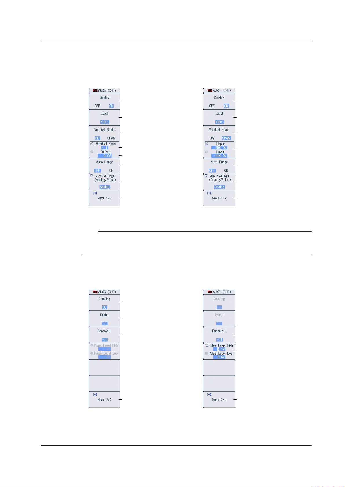
AUX Menu
Set the upper and lower limits of
When the zoom method is
When the zoom method is
set to DIV
* You can turn auto range on and off when the AUX input signal type is set to Analog. If the type is set to
Pulse, auto range is fixed to OFF.
320kHz, 640kHz, 1.28MHz, 2MHz,
When the AUX input signal
type is Analog
When the AUX input signal
Press U2(CH3), I2(CH4), U3(CH5), I3(CH6), U4(CH7), or I4(CH8) to select a channel on an
1.
installed AUX module. The following menu appears.
2.4 Configuring Sensor Input Voltage Measurements
set to SPAN
Note
Turns the waveform display on
and off
Set the display label.
Set the zoom method to DIV.
Set the zoom magnification.
Set the offset.
Turns the auto range on and off*
AUX settings
Displays the second
page of the menu
The U or I key whose display setting is ON illuminates. If the U or I key is not illuminated, you can press it
to turn on the waveform display and the key. If the U or I key is illuminated, you can press it to turn off the
waveform display and the key.
Turns the waveform display on
and off
Set the display label.
Set the zoom method to SPAN.
the display range.
Turns the auto range on and off*
AUX settings
Displays the second
page of the menu
Press the
2.
Next 1/2 soft key to display the 2/2 menu.
type is Pulse
Set the input coupling (AC, DC,
GND).
Set the probe attenuation (1:1,
10:1, 100:1, 1000:1).
Set the bandwidth limit (10kHz,
20kHz, 40kHz, 80kHz, 160kHz,
320kHz, 640kHz, 1.28MHz, 2MHz,
Full).
Displays the first page
of the menu
Set the bandwidth limit (10kHz,
20kHz, 40kHz, 80kHz, 160kHz,
Full).
Set the upper and lower pulse
reference levels.
Displays the first page
of the menu
IM PX8000-02EN
2-11
Page 29
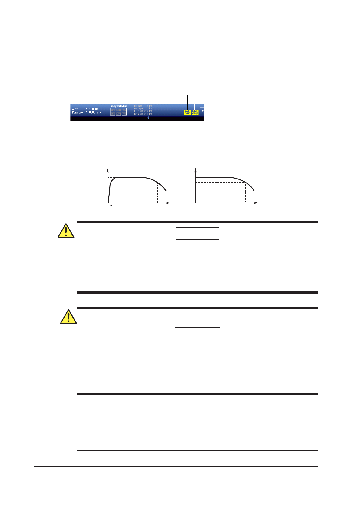
Displays the specified input coupling
–3 dB point
Attenuation
If AC is selected If DC is selected
–3 dB point for AC coupling
2.4 Configuring Sensor Input Voltage Measurements
Setting the Input Coupling (Coupling)
AC: Only displays the waveform produced from the input signal’s AC component.
DC: Displays the waveform produced from both the DC and AC components of the input signal.
GND: Displays the ground level.
Input Coupling and Frequency Response
The frequency responses when the input coupling is set to AC and DC are shown below.
Note that the PX8000 does not acquire low-frequency signals or signal components if the input
coupling is set to AC as indicated in the figure below.
Attenuation
0 dB
–3 dB
If AC is selected
If GND is selected
Nothing is displayed if DC is selected.
0 dB
–3 dB
Input frequency Input frequency
–3 dB point
CAUTION
If the input coupling is AC, in accordance with the frequency response, the input signal is attenuated
more in lower frequencies. As a result, even when a high voltage signal is actually applied, it may not
be measured as a high voltage signal. Furthermore, the PEAK OVER message may not be displayed
on the screen. As necessary, switch the input coupling to DC to check the input signal voltage.
Applying an input signal whose voltage exceeds the maximum input voltage of the AUX
module may damage the input section.
French
ATTENTION
Si le courant du couplage d’entrée est alternatif (CA), conforme à la réponse en fréquence, le
signal d’entrée est davantage atténué aux fréquences plus basses. Par conséquent, même si
vous appliquez un signal de tension élevée, ce dernier risque de ne pas être mesuré comme
tel. De plus, le message de dépassement de plage (PEAK OVER) risque de ne pas s’afficher à
l’écran. Le cas échéant, basculez le couplage d’entrée sur CC (courant continu) afin de vérifier
la tension du signal d’entrée.
Si la tension du signal d’entrée dépasse la tension d’entrée maximale du module AUX, la
section d’entrée risque d’être endommagée.
Setting the Probe Attenuation (Probe)
1:1, 10:1, 100:1, 1000:1: Displays the voltage probe attenuation
Note
If the probe attenuation is not set correctly, the input signal voltage will not be displayed correctly. For
example, if you use a 10:1 voltage probe but set the probe type to 1:1, the automatically measured amplitude
2-12
of the waveform will be 1/10 the real value.
IM PX8000-02EN
Page 30
When the input signal type is Analog When the input signal type is Pulse
2.4 Configuring Sensor Input Voltage Measurements
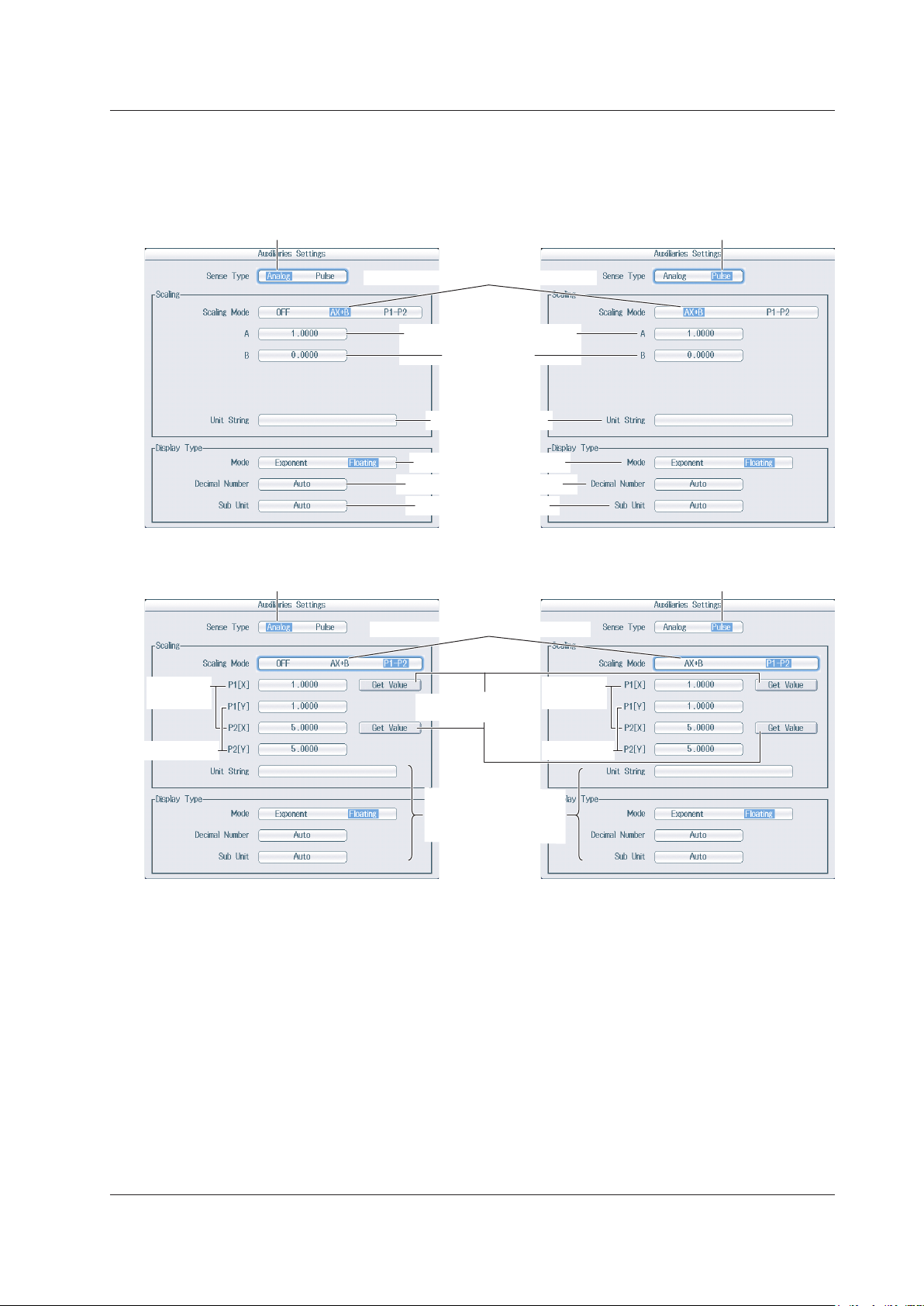
AUX Settings (Aux Settings)
Press the Aux Settings soft key to display the following screen.
• When the linear scaling mode is AX+B • When the linear scaling mode is AX+B
Set the input signal type to Analog.
Set the linear scaling mode to AX+B.
Set the scaling coefficient.
Set the offset.
Set the unit string.
Select the display mode.
Select the decimal place.
Select the unit prefix.
Set the input signal type to Pulse.
• When the linear scaling mode is P1-P2 • When the linear scaling mode is P1-P2
Set the input signal type to Analog. Set the input signal type to Pulse.
Set the linear scaling mode P1-P2.
Measured
values
Scale values
Retrieve the current
measured values
Same feature as when
linear scaling mode is
set to AX+B
Measured
values
Scale value
IM PX8000-02EN
2-13
Page 31

Top row: Measurement range for the displayed waveforms
currently being set.
2.4 Configuring Sensor Input Voltage Measurements
Setting the Sensor Input Voltage Measurement Range (Vertical
Scale, RANGE Knob)
This section explains how to set a fixed range.
(If Auto Range in the AUX menu is set to ON, the measurement range changes depending on the
amplitude of the input signal.)
Turn the RANGE knob to set the sensor input voltage measurement range.
• Auto Range in the AUX menu is set to OFF.
• If you turn the RANGE knob when waveform acquisition is stopped, two values are shown on the
measurement range screen. The upper value is the measurement range for the displayed waveforms.
The lower value is the measurement range that you have specified. The new range will be applied the
next time waveform acquisition is started.
• If you do not operate the RANGE knob for approximately 3 seconds, the measurement range that you
are setting with the knob will disappear from the screen.
Bottom row: Measurement range that you have specified
When the displayed waveform’s measurement range and the measurement range
that you have set are the same, only the bottom row is displayed.
Use the RANGE knob to display
the measurement range that is
Measurement Range Options and Units
Below are the available options for the RANGE knob, measurement range values, and
measurement range units that appear on the screen for when the zoom method is set to DIV and
the zoom magnification is set to ×1. If you change the zoom method or zoom magnification, what
appears on the screen will change accordingly.
• When Waveform Acquisition Is Stopped
Input
Signal
Type
Analog OFF (When the probe
Pulse — 1, 2, 5, 10, 20, 50,
Linear
Scaling Mode
AX+B,
P1‒P2
Available Options
for the RANGE Knob
attenuation is 10:1)
500.0mV,
1.000V,
2.500V,
5.000V,
10.00V,
25.00V,
50.00V,
100.0V,
250.0V,
500.0V,
1.000kV
The available options
vary depending on
the probe attenuation
setting.
100, 200, 500, 1k,
2k, 5k, 10k, 20k, 50k,
100k, 200k, 500k, 1M
Measurement Range
Values
(that appear on the screen)
Upper value:
RANGE knob value for the
displayed waveform
Lower value:
Available option value of
the RANGE knob
Upper value:
Value obtained by
multiplying the available
option value of the RANGE
knob by the linear scaling
coefficient.
Lower value:
Available option value of
the RANGE knob
Upper value:
No display
Lower value:
Available option value of
the RANGE knob
Measurement Range Units
(that appear on the screen)
Upper unit value:
Same unit as the available
options for the RANGE
knob
Lower unit value:
Same unit as the available
options for the RANGE
knob
Upper unit value:
Unit specified on the AUX
setting screen
Lower unit value:
Same unit as the available
options for the RANGE
knob
Upper unit value:
No display
Lower unit value:
Unit specified on the AUX
setting screen
2-14
IM PX8000-02EN
Page 32

Vertical position of the displayed waveform
This indicates that you can press the vertical POSITION knob
to set the vertical position to 0 div.
2.4 Configuring Sensor Input Voltage Measurements
• When Waveform Acquisition Is Running
Input
Signal
Type
Analog OFF (When the probe
Pulse — 1, 2, 5, 10, 20, 50, 100,
Linear
Scaling Mode
AX+B,
P1‒P2
Available Options
for the RANGE Knob
attenuation is 10:1)
500.0mV,
1.000V,
2.500V,
5.000V,
10.00V,
25.00V,
50.00V,
100.0V,
250.0V,
500.0V,
1.000kV
The available options
vary depending on
the probe attenuation
setting.
200, 500, 1k, 2k, 5k,
10k, 20k, 50k, 100k,
200k, 500k, 1M
Measurement Range
Values
(that appear on the screen)
Upper value:
No display
Lower value:
Available option value of
the RANGE knob
Upper value:
Value obtained by
multiplying the available
option value of the RANGE
knob by the linear scaling
coefficient.
Lower value:
Available option value of
the RANGE knob
Upper value:
No display
Lower value:
Available option value of
the RANGE knob
Measurement Range Units
(that appear on the screen)
Upper unit value:
No display
Lower unit value:
Same unit as the
available options for the
RANGE knob
Upper unit value:
Unit specified on the AUX
setting screen
Lower unit value:
Same unit as the
available options for the
RANGE knob
Upper unit value:
No display
Lower unit value:
Unit specified on the AUX
setting screen
Setting the Sensor Input Voltage Waveform Vertical Position
When the Zoom Method is Set to DIV (Vertical POSITION Knob)
Turn the vertical POSITION knob to set the waveform vertical position.
• Set in the range of –5.00 div to 5.00 div.
• If you do not operate the vertical POSITION knob for approximately 3 seconds, the vertical position that
you are setting with the knob will disappear from the screen.
Use the vertical POSITION knob to display the vertical
position that is currently being set.
• You can set the vertical position to 0 div by pressing the knob.
RANGE knob
Vertical POSITION knob
IM PX8000-02EN
2-15
Page 33

2.4 Configuring Sensor Input Voltage Measurements
When the Zoom Method is Set to SPAN (Upper and Lower Limits)
Using the Upper/Lower soft key and the jog shuttle, set the voltage at the top edge of the waveform
screen (upper limit) and the voltage at the bottom edge of the screen (lower limit) to set the waveform
vertical position.
Set the upper and lower limits of the display range.
2-16
IM PX8000-02EN
Page 34

2.5 Configuring Rotating Speed Measurements
This section explains the following settings for the vertical axis of rotating speed measurements.
• Waveform display on and off
• Display labels
• Zoom method
DIV: Magnification for zooming waveforms, offset
SPAN: Upper and lower display limits for zooming waveforms
• Auto range on and off
• Rotating speed measurement
Input signal type, linear scaling, display format
• Input coupling
• Bandwidth limit
• Upper and lower pulse reference levels
• Rotating speed measurement range
• Rotating speed waveform vertical position
► Features Guide: “Sensor Input Voltage Measurement (AUX)”
“Rotating Speed Settings (Speed Settings)”
Check that an AUX module is installed in slot 3, 5, or 7.
Pm Menu
Of the ELEM 2 to ELEM 4 keys, press the key corresponding to the slot in which the AUX module is
installed. On the menu that appears, set Motor Mode to ON.
Set Motor Mode to ON.
Set the function name.
Set the scaling coefficient.
Set the unit.
Set the synchronization source. ► section 1.3
IM PX8000-02EN
2-17
Page 35

Set the upper and lower limits of
When the zoom method is
When the zoom method is
set to DIV
* You can turn auto range on and off when the rotating-speed input signal type is set to Analog. If the type
is set to Pulse, auto range is fixed to OFF.
320kHz, 640kHz, 1.28MHz, 2MHz,
When the rotating-speed input signal
type is Analog
When the rotating-speed input signal
2.5 Configuring Rotating Speed Measurements
AUX Menu
Press U2(CH3), U3(CH5), or U4(CH7) to select a channel on an installed AUX module. The
1.
following menu appears.
set to SPAN
Note
Turns the waveform display on
and off
Set the display label.
Set the zoom method to DIV.
Set the zoom magnification.
Set the offset.
Turns the auto range on and off*
Configure rotating
speed measurement.
Displays the second
page of the menu
The U key whose display setting is ON illuminates. If the U key is not illuminated, you can press it to turn on
the waveform display and the key. If the U key is illuminated, you can press it to turn off the waveform display
and the key.
Turns the waveform display on
and off
Set the display label.
Set the zoom method to SPAN.
the display range.
Turns the auto range on and off*
Configure rotating
speed measurement.
Displays the second
page of the menu
2.
Press the
Next 1/2 soft key to display the 2/2 menu.
type is Pulse
Set the input coupling (AC, DC,
GND).
Set the bandwidth limit (10kHz,
20kHz, 40kHz, 80kHz, 160kHz,
320kHz, 640kHz, 1.28MHz, 2MHz,
Full).
Displays the first page
of the menu
Set the bandwidth limit (10kHz,
20kHz, 40kHz, 80kHz, 160kHz,
Full).
Set the upper and lower pulse
reference levels.
Displays the first page
of the menu
2-18
IM PX8000-02EN
Page 36

When the input signal type is Analog
• When the linear scaling mode is AX+B
• When the linear scaling mode is P1-P2
When the input signal type is Pulse
2.5 Configuring Rotating Speed Measurements
Setting the Input Coupling (Coupling)
This is the same feature as the input coupling of sensor input voltage measurement. ► section 2.4
Configuring Rotating Speed Measurements (Speed Settings)
Press the Speed Settings soft key to display the following screen.
Set the input signal type to Analog.
Select the rotating speed unit (rps, rpm, rph).
Set the linear scaling mode to AX+B.
Set the scaling coefficient.
Set the offset.
Select the display mode.
Select the number of decimal places.
Select the unit prefix.
Set the input signal type to Analog.
Select the rotating speed unit (rps, rpm, rph).
Set the linear scaling mode P1-P2.
Retrieve the current measured values.
Set the measured values.
Set the scale values.
Same feature as when linear scaling mode is
set to AX+B
Set the input signal type to Pulse.
Select the rotating speed unit (rps, rpm, rph).
Set the number of pulses per rotation (1-9999).
IM PX8000-02EN
Same feature as when the input signal type
is set to Analog
2-19
Page 37

Top row: Measurement range for the displayed waveforms
2.5 Configuring Rotating Speed Measurements
Setting the Rotating Speed Measurement Range
(Vertical Scale, RANGE Knob)
This section explains how to set a fixed range.
(If Auto Range in the AUX menu is set to ON, the measurement range changes depending on the
amplitude of the input signal.)
Turn the RANGE knob to set the rotating speed measurement range.
• Auto Range in the AUX menu is set to OFF.
• If the input signal type is analog and you turn the RANGE knob when waveform acquisition is stopped,
two values are shown on the measurement range screen. The upper value is the measurement range
for the displayed waveforms. The lower value is the measurement range that you have specified. The
new range will be applied the next time waveform acquisition is started.
• If you do not operate the RANGE knob for approximately 3 seconds, the measurement range that you
are setting with the knob will disappear from the screen.
Bottom row: Measurement range that you have specified
Use the RANGE knob to display
the measurement range that is
currently being set.
Measurement Range Options and Units
Below are the available options for the RANGE knob, measurement range values, and
measurement range units that appear on the screen for when the zoom method is set to DIV and
the zoom magnification is set to ×1. If you change the zoom method or zoom magnification, what
appears on the screen will change accordingly.
• When Waveform Acquisition Is Stopped
Input
Signal
Type
Analog OFF 50.00mV,
Pulse — 1, 2, 5, 10, 20, 50, 100,
Linear
Scaling
Mode
AX+B,
P1‒P2
Available Options
for the RANGE Knob
100.0mV,
250.0mV,
500.0mV,
1.000V,
2.500V,
5.000V,
10.00V,
25.00V,
50.00V,
100.0V
200, 500, 1k, 2k, 5k,
10k, 20k, 50k, 100k,
200k, 500k, 1M
Measurement Range
Values
(that appear on the screen)
Upper value:
RANGE knob value for
the displayed waveform
Lower value:
Available option value of
the RANGE knob
Upper value:
Value obtained by
multiplying the available
option value of the
RANGE knob by the linear
scaling coefficient.
Lower value:
Available option value of
the RANGE knob
Upper value:
No display
Lower value:
Available option value of
the RANGE knob
Measurement Range Units
(that appear on the screen)
Upper unit value:
Unit selected on the rotating
speed measurement setting
screen
Lower unit value:
Same unit as the available
options for the RANGE knob
Upper unit value:
Unit selected on the rotating
speed measurement setting
screen
Lower unit value:
Same unit as the available
options for the RANGE knob
Upper unit value:
No display
Lower unit value:
Unit selected on the rotating
speed measurement setting
screen
2-20
IM PX8000-02EN
Page 38

• When Waveform Acquisition Is Running
Vertical position of the displayed waveform
This indicates that you can press the vertical POSITION knob
to set the vertical position to 0 div.
Input
Signal
Type
Analog OFF 50.00mV,
Pulse — 1, 2, 5, 10, 20, 50,
Linear
Scaling
Mode
AX+B,
P1‒P2
Available Options
for the RANGE Knob
100.0mV,
250.0mV,
500.0mV,
1.000V,
2.500V,
5.000V,
10.00V,
25.00V,
50.00V,
100.0V
100, 200, 500, 1k,
2k, 5k, 10k, 20k, 50k,
100k, 200k, 500k, 1M
Measurement Range
Values
(that appear on the screen)
Upper value:
Lower value:
Upper value:
Lower value:
Upper value:
Lower value:
2.5 Configuring Rotating Speed Measurements
Measurement Range Units
(that appear on the screen)
Upper unit value:
Available option value of
the RANGE knob
Available option value of
the RANGE knob
Value obtained by
multiplying the available
option value of the
RANGE knob by the linear
scaling coefficient.
Available option value of
the RANGE knob
No display
Available option value of
the RANGE knob
Unit selected on the rotating
speed measurement setting
screen
Lower unit value:
Same unit as the available
options for the RANGE knob
Upper unit value:
Unit selected on the rotating
speed measurement setting
screen
Lower unit value:
Same unit as the available
options for the RANGE knob
Upper unit value:
No display
Lower unit value:
Unit selected on the rotating
speed measurement setting
screen
Setting the Rotating Speed Waveform Vertical Position
When the Zoom Method is Set to DIV (Vertical POSITION Knob)
Turn the vertical POSITION knob to set the waveform vertical position.
• Set in the range of –5.00 div to 5.00 div.
• If you do not operate the vertical POSITION knob for approximately 3 seconds, the vertical position that
you are setting with the knob will disappear from the screen.
Use the vertical POSITION knob to display the vertical
position that is currently being set.
• You can set the vertical position to 0 div by pressing the knob.
RANGE knob
Vertical POSITION knob
IM PX8000-02EN
2-21
Page 39

Set the upper and lower limits of
2.5 Configuring Rotating Speed Measurements
When the Zoom Method is Set to SPAN (Upper and Lower Limits)
Using the Upper/Lower soft key and the jog shuttle, set the number of rotations at the top edge of
the waveform screen (upper limit) and the number of rotations at the bottom edge of the screen (lower
limit) to set the waveform vertical position.
the display range.
2-22
IM PX8000-02EN
Page 40

2.6 Configuring Torque Measurements
This section explains the following settings for the vertical axis of torque measurements.
• Waveform display on and off
• Display labels
• Zoom method
DIV: Magnification for zooming waveforms, offset
SPAN: Upper and lower display limits for zooming waveforms
• Auto range on and off
• Torque measurement
Input signal type, linear scaling, display format
• Input coupling
• Bandwidth limit
• Upper and lower pulse reference levels
• Torque measurement range
• Torque waveform vertical position
► Features Guide: “Sensor Input Voltage Measurement (AUX)”
“Torque Settings (Torque Settings)”
Check that an AUX module is installed in slot 3, 5, or 7.
Pm Menu
Of the ELEM 2 to ELEM 4 keys, press the key corresponding to the slot in which the AUX module is
installed. On the menu that appears, set Motor Mode to ON.
Set Motor Mode to ON.
Set the function name.
Set the scaling coefficient.
Set the unit.
Set the synchronization source. ► section 1.3
IM PX8000-02EN
2-23
Page 41

When the zoom method is
When the zoom method is
set to DIV
* You can turn auto range on and off when the torque input signal type is set to Analog. If the type is set to
Pulse, auto range is fixed to OFF.
320kHz, 640kHz, 1.28MHz, 2MHz,
When the torque input signal
type is Analog
When the torque input signal
2.6 Configuring Torque Measurements
AUX Menu
Press I2(CH4), I3(CH6), or I4(CH8) to select a channel on an installed AUX module. The
1.
following menu appears.
set to SPAN
Turns the waveform display on
and off
Set the display label.
Set the zoom method to DIV.
Set the zoom magnification.
Set the offset.
Turns the auto range on and off*
Configure torque measurements.
Displays the second
page of the menu
Turns the waveform display on
and off
Set the display label.
Set the zoom method to SPAN.
Set the upper and lower limits of
the display range.
Turns the auto range on and off*
Configure torque measurements.
Displays the second
page of the menu
Note
The I key whose display setting is ON illuminates. If the I key is not illuminated, you can press it to turn on
the waveform display and the key. If the I key is illuminated, you can press it to turn off the waveform display
and the key.
Press the
2.
Next 1/2 soft key to display the 2/2 menu.
type is Pulse
Set the input coupling (AC, DC,
GND).
Set the bandwidth limit (10kHz,
20kHz, 40kHz, 80kHz, 160kHz,
320kHz, 640kHz, 1.28MHz, 2MHz,
Full).
Displays the first page
of the menu
Set the bandwidth limit (10kHz,
20kHz, 40kHz, 80kHz, 160kHz,
Full).
Set the upper and lower pulse
reference levels.
Displays the first page
of the menu
2-24
IM PX8000-02EN
Page 42

When the input signal type is Analog
• When the linear scaling mode is AX+B
• When the linear scaling mode is P1-P2
When the input signal type is Pulse
2.6 Configuring Torque Measurements
Setting the Input Coupling (Coupling)
This is the same feature as the input coupling of sensor input voltage measurement. ► section 2.4
Configuring Torque Measurements (Torque Settings)
Press the Torque Settings soft key to display the following screen.
Set the input signal type to Analog.
Set the torque unit.
Set the linear scaling mode to AX+B.
Set the scaling coefficient.
Set the offset.
Select the display mode.
Select the number of decimal places.
Select the unit prefix.
Set the input signal type to Analog.
Set the torque unit.
Set the linear scaling mode P1-P2.
Retrieve the current measured values.
Set the measured values.
Set the scale values.
Same feature as when linear scaling mode is
set to AX+B
Set the input signal type to Pulse.
Set the torque unit.
Set the positive and negative rated torque
signal values
(-10000.0000 to 10000.0000).
Set the positive and negative rated torque
signals’ pulse signal values
(1Hz-100000000Hz).
IM PX8000-02EN
Same feature as when the input signal type
is set to Analog
2-25
Page 43

Top row: Measurement range for the displayed waveforms
2.6 Configuring Torque Measurements
Setting the Torque Measurement Range
(Vertical Scale, RANGE Knob)
This section explains how to set a fixed range.
(If Auto Range in the AUX menu is set to ON, the measurement range changes depending on the
amplitude of the input signal.)
Turn the RANGE knob to set the torque measurement range.
• Auto Range in the AUX menu is set to OFF.
• If the input signal type is analog and you turn the RANGE knob when waveform acquisition is stopped,
two values are shown on the measurement range screen. The upper value is the measurement range
for the displayed waveforms. The lower value is the measurement range that you have specified. The
new range will be applied the next time waveform acquisition is started.
• If you do not operate the RANGE knob for approximately 3 seconds, the measurement range that you
are setting with the knob will disappear from the screen.
Bottom row: Measurement range that you have specified
Use the RANGE knob to display
the measurement range that is
currently being set.
Measurement Range Options and Units
Below are the available options for the RANGE knob, measurement range values, and
measurement range units that appear on the screen for when the zoom method is set to DIV and
the zoom magnification is set to ×1. If you change the zoom method or zoom magnification, what
appears on the screen will change accordingly.
• When Waveform Acquisition Is Stopped
Input
Signal
Type
Analog OFF 50.00mV,
Pulse — 1, 2, 5, 10, 20, 50,
Linear
Scaling
Mode
AX+B,
P1‒P2
Available Options
for the RANGE
Knob
100.0mV,
250.0mV,
500.0mV,
1.000V,
2.500V,
5.000V,
10.00V,
25.00V,
50.00V,
100.0V
100, 200, 500, 1k,
2k, 5k, 10k, 20k,
50k, 100k, 200k,
500k, 1M
Measurement Range
Values
(that appear on the screen)
Upper value:
RANGE knob value for
the displayed waveform
Lower value:
Available option value of
the RANGE knob
Upper value:
Value obtained by
multiplying the available
option value of the
RANGE knob by the linear
scaling coefficient.
Lower value:
Available option value of
the RANGE knob
Upper value:
No display
Lower value:
Available option value of
the RANGE knob
Measurement Range Units
(that appear on the screen)
Upper unit value:
Unit selected on the torque speed
measurement setting screen
Lower unit value:
Same unit as the available
options for the RANGE knob
Upper unit value:
Unit selected on the torque speed
measurement setting screen
Lower unit value:
Same unit as the available
options for the RANGE knob
Upper unit value:
No display
Lower unit value:
Unit selected on the torque speed
measurement setting screen
2-26
IM PX8000-02EN
Page 44

Vertical position of the displayed waveform
This indicates that you can press the vertical POSITION knob
to set the vertical position to 0 div.
2.6 Configuring Torque Measurements
• When Waveform Acquisition Is Running
Input
Signal
Type
Analog OFF 50.00mV,
Pulse — 1, 2, 5, 10, 20, 50,
Linear
Scaling
Mode
AX+B,
P1‒P2
Available Options
for the RANGE
Knob
100.0mV,
250.0mV,
500.0mV,
1.000V,
2.500V,
5.000V,
10.00V,
25.00V,
50.00V,
100.0V
100, 200, 500, 1k,
2k, 5k, 10k, 20k, 50k,
100k, 200k, 500k,
1M
Measurement Range
Values
(that appear on the screen)
Upper value:
Available option value of
the RANGE knob
Lower value:
Available option value of
the RANGE knob
Upper value:
Value obtained by
multiplying the available
option value of the
RANGE knob by the linear
scaling coefficient.
Lower value:
Available option value of
the RANGE knob
Upper value:
No display
Lower value:
Available option value of
the RANGE knob
Setting the Torque Waveform Vertical Position
Measurement Range Units
(that appear on the screen)
Upper unit value:
Unit selected on the torque speed
measurement setting screen
Lower unit value:
Same unit as the available
options for the RANGE knob
Upper unit value:
Unit selected on the torque speed
measurement setting screen
Lower unit value:
Same unit as the available
options for the RANGE knob
Upper unit value:
No display
Lower unit value:
Unit selected on the torque speed
measurement setting screen
When the Zoom Method is Set to DIV (Vertical POSITION Knob)
Turn the vertical POSITION knob to set the waveform vertical position.
• Set in the range of –5.00 div to 5.00 div.
• If you do not operate the vertical POSITION knob for approximately 3 seconds, the vertical position that
• You can set the vertical position to 0 div by pressing the knob.
you are setting with the knob will disappear from the screen.
Use the vertical POSITION knob to display the vertical
position that is currently being set.
RANGE knob
Vertical POSITION knob
IM PX8000-02EN
2-27
Page 45

Set the upper and lower limits of
2.6 Configuring Torque Measurements
When the Zoom Method is Set to SPAN (Upper and Lower Limits)
Using the Upper/Lower soft key and the jog shuttle, set the torque at the top edge of the waveform
screen (upper limit) and the torque at the bottom edge of the screen (lower limit) to set the waveform
vertical position.
the display range.
2-28
IM PX8000-02EN
Page 46

2.7 Displaying the Menu for Configuring All
Displaying the settings of all elements Displaying the settings of all AUX channels
Channels
This section explains the following settings for configuring all channels.
• Settings of all elements
• Settings of all AUX channels
• Copying setup data
► Features Guide: “Displaying the Menu for Configuring All Channels (ALL CH)”
ALL CH menu
Press ALL CH to display the following menu.
Press the All Elements soft key.
Press the All Auxiliaries soft
key.
Turns independent element
configuration on and off
Set the display format of
external current sensor range
(Direct, Measure).
Copies element setup data Copies AUX channel setup data
Settings of All Elements (All Elements)
Press the All Elements soft key to display the following screen.
1.
Use the jog shuttle to select the setting that you want to change, and then press SET to display the
available options or an input box.
To set all elements to the same setting at once,
change the settings in the All column.
IM PX8000-02EN
Use the jog shuttle to select the item
that you want to set.
2-29
Page 47

2.7 Displaying the Menu for Configuring All Channels
Copying Element Setup Data (Elements Copy to)
2.
Press the
Elements Copy to soft key to display the following screen.
Settings of All AUX Channels
Press the
1.
Use the jog shuttle to select the setting that you want to change, and then press SET to display the
available options or an input box.
All Auxiliaries soft key to display the following screen.
Set the copy source element.
Selects all elements except the copy source to be copy
destinations
Clears all elements from being copy destinations
Select the element check boxes separately to set the
copy destination.
Starts copying
Copying AUX Channel Setup Data (Auxiliaries Copy to)
2.
Press the
Use the jog shuttle to select the item
that you want to set.
Auxiliaries Copy to soft key to display the following screen.
Set the copy source channel.
Selects all channels except the copy source to be copy
destinations
Clears all channels from being copy destinations
Select the channel check boxes separately to set the
copy destination.
Starts copying
2-30
IM PX8000-02EN
Page 48

2.8 Configuring the Horizontal Axis (Time axis)
This section explains how to set the time scale (the time per grid (1 div) displayed on the screen).
► Features Guide: “Horizontal Axis”
Configuring the Horizontal Axis (Time axis)
Turn the TIME/DIV knob to set the time scale.
TIME/DIV knob
Time Scale (TIME/DIV) Display
• If you turn the TIME/DIV knob when waveform acquisition is stopped, the time scale display shows
the time scale for the currently displayed waveform in the upper row and the changed time scale in
the lower row. The new time scale will be applied the next time waveform acquisition is started.
• If you do not operate the TIME/DIV knob for approximately 3 seconds, the time scale that you are
setting with the knob will disappear from the screen.
Top row:
Acquisition mode
Bottom row:
Time scale for the displayed waveform
Turn the TIME/DIV knob.
Top row:
Time scale for the displayed waveform
Bottom row:
Use the TIME/DIV knob to display the time scale
that is currently being set.
Time scale that you have specified
IM PX8000-02EN
2-31
Page 49

* Displayed when the trigger mode is set to SingleN.
Chapter 3 Triggering
3.1 Setting the Trigger Mode
This section explains the following setting for updating the displayed waveform.
• Trigger mode
MODE menu
Press MODE to display the following menu.
Trigger mode
► Features Guide: “Trigger Mode (MODE)”
MODE Key
Set the number of waveforms to acquire.*
Setting the Trigger Mode (Mode)
Auto: If the trigger conditions are met within 50 ms, the PX8000 updates the displayed waveforms
on each trigger occurrence. If not, the PX8000 automatically updates the displayed
waveforms. If the time axis is set to a value that would cause the display to switch to roll
mode, the roll mode display will be enabled.
AutoLevel: If a trigger occurs before a timeout (which is approximately 1 second), the PX8000 updates
the waveform in the same way that it does in Auto mode. If a trigger does not occur before
a timeout, the PX8000 automatically changes the trigger level to the center value of the
trigger source amplitude, triggers on that value, and updates the displayed waveform.
Normal: The PX8000 only updates the waveform display when the trigger conditions are met.
Single: When the trigger conditions are met, the PX8000 updates the displayed waveform once
and stops signal acquisition. If the time axis is set to a value that would cause the display
to switch to roll mode, the roll mode display will be enabled. When the PX8000 triggers, it
begins recording data. When data has been acquired up to the amount specified by the set
record length, the waveform display stops.
SingleN: The PX8000 acquires signals each time the trigger conditions are met until a specified
number of signals have been acquired, and then displays all of the acquired signals. If no
triggers occur, the display is not updated.
On Start: Regardless of the trigger settings, when you press the START key, the PX8000 updates the
displayed waveforms once and stops signal acquisition. If the time axis is set to a value that
would cause the display to switch to roll mode, the roll mode display will be enabled. When
data has been acquired up to the amount specified by the set record length, the waveform
display stops.
IM PX8000-02EN
3-1
Page 50

3.2 Setting the Trigger Position and Trigger Delay
Set the trigger position to 10%.
Set the trigger position to 50%.
Set the trigger position to 90%.
This section explains the following settings for updating the displayed waveform.
• Trigger position
• Trigger delay
► Features Guide: “Trigger Position (Position)”
“Trigger Delay (Delay)”
POSITION/DELAY Menu
Press POSITION/DELAY to display the following menu.
Set the trigger position.
Set the trigger delay.
3-2
IM PX8000-02EN
Page 51

3.3 Setting the Trigger Hold Off
Set the trigger hold off.
This section explains the following setting for updating the displayed waveform.
• Hold-off time
► Features Guide: “Trigger Hold Off (Hold Off)”
SIMPLE/ENHANCED Menu
Press SIMPLE/ENHANCED to display the following menu.
Setting the Hold-off Time (Hold Off)
The trigger hold-off feature temporarily stops the detection of the next trigger once a trigger has
occurred.
IM PX8000-02EN
3-3
Page 52

3.4 Triggering on an Edge Trigger (Simple)
Set the trigger hysteresis ( , , ).
This section explains the following settings for triggering on the edges of a signal applied to an
installed module.
• Trigger source
• Trigger slope
• Trigger level
• Trigger hysteresis
► Features Guide: “Simple Trigger (Simple),” “Trigger Source (Source),”
“Trigger Slope (Slope),” “Trigger Level (Level),” and
“Trigger Hysteresis (Hysteresis)”
SIMPLE Menu
Press SIMPLE/ENHANCED and then the Setting soft key to select Simple. The following menu
appears.
Set Setting to Simple.
Set the trigger source
(U1-U4, I1-I4, P1-P4, AUX3-AUX8).
Set the trigger slope ( , , ).
Set the trigger level.
Set the trigger hold off. ► section 3.3
3-4
IM PX8000-02EN
Page 53

3.5 Triggering on a Timer Trigger (Simple)
Set Setting to Simple.
Set the date and time.
Confirms the date and time
This section explains the settings that are used when triggering on a specific date and time.
► Features Guide: “Time (Time)”
SIMPLE Time Menu
Press SIMPLE/ENHANCED and then the Setting soft key to select Simple. The following menu
appears.
Set Source to Time.
Set the time interval.
Setting the Date and Time (Date/Time Setup)
Press the Date/Time Setup soft key to display the following screen.
Set the date and time.
IM PX8000-02EN
3-5
Page 54

3.6 Triggering on an External Trigger (Simple)
Set the trigger hold off. ► section 3.3
This section explains the settings that are used when triggering on an external signal.
► Features Guide: “External Signal (External)”
“Trigger Slope (Slope)”
SIMPLE External Menu
Press SIMPLE/ENHANCED and then the Setting soft key to select Simple. The following menu
appears.
Set Setting to Simple.
Set Source to External.
Set the trigger slope ( , ).
3-6
IM PX8000-02EN
Page 55

3.7 Triggering on a Power Line Signal (Simple)
Set the trigger hold off. ► section 3.3
This section explains the settings that are used when triggering on a power line signal.
► Features Guide: “Power Line Signal (Line)”
SIMPLE Line Menu
Press SIMPLE/ENHANCED and then the Setting soft key to select Simple. The following menu
appears.
Set Setting to Simple.
Set Source to Line.
IM PX8000-02EN
3-7
Page 56

3.8 Triggering on an A -> B(N) Trigger (Enhanced)
Set the trigger hold off. ► section 3.3
Set the state condition (H, L, or X (do not use as a trigger source)).
Set the state condition achievement conditions
This section explains the following settings for triggering on an A -> B(N) trigger.
• Trigger source
• State condition
• State condition achievement condition
• Number of times state condition B must be met
• Trigger condition
► Features Guide: “A -> B(N) Trigger (Enhanced)”
ENHANCED_A->B(N) Trigger Menu
Press SIMPLE/ENHANCED and then the Setting soft key to select Enhanced. The following menu
appears.
Set Setting to Enhanced.
Set Type to A -> B(N).
Set the state and trigger conditions.
Setting the State and Trigger Conditions (Set Pattern)
Press the Set Pattern soft key to display the following menu.
Set the trigger level.
Set the hysteresis ( , , ).
(Enter, Exit).
Set the number of times state condition B
must be met.
3-8
IM PX8000-02EN
Page 57

3.9 Triggering on an A Delay B Trigger (Enhanced)
Set the trigger hold off. ► section 3.3
Set the state condition achievement conditions
Set the state condition (H, L, or X (do not use as a trigger source)).
This section explains the following settings for triggering on an A Delay B trigger.
• Trigger source
• State condition
• State condition achievement condition
• Delay time
• Trigger condition
► Features Guide: “A Delay B Trigger (Enhanced)”
ENHANCED A Delay B Trigger Menu
Press SIMPLE/ENHANCED and then the Setting soft key to select Enhanced. The following menu
appears.
Set Setting to Enhanced.
Set Type to A Delay B.
Set the state and trigger conditions.
Setting the State and Trigger Conditions (Set Pattern)
Press the Set Pattern soft key to display the following menu.
Set the trigger level.
Set the hysteresis ( , , ).
(Enter, Exit).
Set the delay time.
IM PX8000-02EN
3-9
Page 58

3.10 Triggering on an Edge On A Trigger (Enhanced)
Set the state condition achievement conditions
Set the state condition (H, L, or X (do not use as a trigger source)).
This section explains the following settings for triggering on an Edge On A trigger.
• Trigger source
• State condition
• State condition achievement condition
• Edge detection condition
• Trigger condition
► Features Guide: “Edge On A Trigger (Enhanced)”
ENHANCED Edge On A Trigger Menu
Press SIMPLE/ENHANCED and then the Setting soft key to select Enhanced. The following menu
appears.
Set Setting to Enhanced.
Set Type to Edge On A.
Set the state and trigger conditions.
Set the trigger hold off. ► section 3.3
Setting the State and Trigger Conditions (Set Pattern)
Press the Set Pattern soft key to display the following menu.
Set the edge detection condition ( , , —).
Set the trigger level.
Set the hysteresis ( , , ).
(True, False).
3-10
IM PX8000-02EN
Page 59

3.11 Triggering on an OR or AND Trigger (Enhanced)
Set the trigger hold off. ► section 3.3
Set the edge detection condition ( , , IN, OUT, —).
This section explains the following settings for triggering on an OR or AND trigger.
• Trigger source
• Edge detection condition (OR trigger)
• Achievement condition (AND trigger)
• Trigger condition
► Features Guide: “OR Trigger (Enhanced)” and “AND Trigger (Enhanced)”
ENHANCED OR Trigger Menu
Press SIMPLE/ENHANCED and then the Setting soft key to select Enhanced. The following menu
appears.
Set Setting to Enhanced.
Set Type to OR.
Set the state and trigger conditions.
Setting the State and Trigger Conditions (Set Pattern)
Press the Set Pattern soft key to display the following menu.
Set the trigger level (set to the center value of the level width if the
edge detection condition is set to IN or OUT).
Set the level width
(when the edge detection condition is set to IN or OUT).
Set the hysteresis ( , , ).
IM PX8000-02EN
3-11
Page 60

Set the trigger hold off. ► section 3.3
Set the achievement condition (H, L, IN, OUT, —).
3.11 Triggering on an OR or AND Trigger (Enhanced)
ENHANCED AND Trigger Menu
Press SIMPLE/ENHANCED and then the Setting soft key to select Enhanced. The following menu
appears.
Set Setting to Enhanced.
Set Type to AND.
Set the state and trigger conditions.
Setting the State and Trigger Conditions (Set Pattern)
Press the Set Pattern soft key to display the following menu.
Set the trigger level (set to the center value of the level width if the
achievement condition is set to IN or OUT).
Set the level width
(when the achievement condition is set to IN or OUT).
Set the hysteresis ( , , ).
3-12
IM PX8000-02EN
Page 61

3.12 Triggering on a Period Trigger (Enhanced)
Set the trigger hold off. ► section 3.3
Set the state condition (H, L, or X (do not use as a trigger source)).
Set Time when the determination mode is T < Time or T >Time.
Set the hysteresis ( , , ).
This section explains the following settings for triggering on a period trigger.
• Trigger source
• State condition
• Determination mode
• Reference time
• Trigger condition
► Features Guide: “Period Trigger (Enhanced)”
ENHANCED Period Trigger Menu
Press SIMPLE/ENHANCED and then the Setting soft key to select Enhanced. The following menu
appears.
Set Setting to Enhanced.
Set Type to Period.
Set the state and trigger conditions.
Setting the State and Trigger Conditions (Set Pattern)
Press the Set Pattern soft key to display the following menu.
Set the trigger level.
Set the determination mode.
Set the reference time.*
* Set T1 and T2 when the determination mode is T1 < T < T2 or T <T1, T2 < T.
IM PX8000-02EN
3-13
Page 62

3.12 Triggering on a Period Trigger (Enhanced)
Setting the Reference Mode (Mode)
Set what kind of relationship must be established between period T and the specified reference
times (Time or T1 and T2) for the PX8000 to trigger.
T < Time Period T must be shorter than the reference time (Time).
T > Time Period T must be longer than the reference time (Time).
T1 < T < T2 Period T must be longer than reference time T1 and shorter than reference time T2.
T < T1, T2 <T Period T must be shorter than reference time T1 or longer than reference time T2.
3-14
IM PX8000-02EN
Page 63

3.13 Triggering on a Pulse Width Trigger (Enhanced)
Set the trigger hold off. ► section 3.3
Set the state condition (H, L, or X (do not use as a trigger source)).
Set Time when the determination mode is B < Time, B >Time, or B TimeOut.
Set the hysteresis ( , , ).
This section explains the following settings for triggering on a pulse width trigger.
• Trigger source
• State condition
• Determination mode
• Reference time
• Trigger condition
► Features Guide: “Pulse Width Trigger (Enhanced)”
ENHANCED Pulse Width Trigger Menu
Press SIMPLE/ENHANCED and then the Setting soft key to select Enhanced. The following menu
appears.
Set Setting to Enhanced.
Set the trigger type to Pulse Width.
Set the state and trigger conditions.
Setting the State and Trigger Conditions (Set Pattern)
Press the Set Pattern soft key to display the following menu.
Set the trigger level.
Set the determination mode.
Set the reference time.*
* Set T1 and T2 when the determination mode is B Between.
IM PX8000-02EN
3-15
Page 64

3.13 Triggering on a Pulse Width Trigger (Enhanced)
Setting the Reference Mode (Mode)
Set what kind of relationship must be established between the state condition B achievement time
and the specified reference times (Time or T1 and T2) for the PX8000 to trigger.
B < Time The PX8000 triggers when the achievement time is shorter than the reference time (Time), and
the state condition changes from being met to not being met.
B > Time The PX8000 triggers when the achievement time is longer than the reference time (Time), and
the state condition changes from being met to not being met.
B TimeOut The PX8000 triggers when the achievement time is longer than the reference time (Time).
B Between The PX8000 triggers when the achievement time is longer than reference time T1 and shorter
than reference time T2, and the state condition changes from being met to not being met.
3-16
IM PX8000-02EN
Page 65

3.14 Triggering on a Wave Window Trigger
Set the trigger hold off. ► section 3.3
Set the source channel (ON, OFF).
* Set when the synchronization channel is U1 to U4, I1 to I4, P1 to P4, or AUX3 to AUX8.
(Enhanced)
This section explains the following settings for triggering on a wave window trigger.
• Source channel
Tolerance width, cycle frequency, and reference cycle
• Synchronization channel
• Trigger condition
► Features Guide: “Wave Window Trigger (Enhanced)”
ENHANCED Wave Window Trigger Menu
Press SIMPLE/ENHANCED and then the Setting soft key to select Enhanced. The following menu
appears.
Set Setting to Enhanced.
Set Type to Wave Window.
Set the trigger conditions.
Setting the Trigger Conditions (Set Pattern)
Press the Set Pattern soft key to display the following menu.
Set the tolerance width.
Set the cycle frequency.
Set the reference cycle.
Set the synchronization channel
(Auto, U1-U4, I1-I4, P1-P4, AUX3-AUX8).
IM PX8000-02EN
Set the level for detecting the start
and end points, and set the detection
hysteresis.*
3-17
Page 66

3.15 Triggering the PX8000 Manually (Manual
Trigger)
This section explains how to trigger the PX8000 manually.
► Features Guide: “Trigger Types (Type)”
Press MANUAL TRIG.
3-18
IM PX8000-02EN
Page 67

* A confirmation message will appear.
* A confirmation message will appear.
Chapter 4 Waveform Acquisition
4.1 Setting Conditions for Waveform Acquisition
This section explains the following settings for acquiring waveforms.
• Record length
• Acquisition mode
• Number of waveforms to acquire and attenuation constant
• Time base
• Executing logger setup
► Features Guide: “Waveform Acquisition”
ACQUIRE Menu
Press ACQUIRE to display the following menu.
When the Acquisition Mode Is Set to Normal or Envelope
Set the record length.
Set the acquisition mode to
Normal or Envelope.
When the Acquisition Mode Is Set to Average
Set the trigger mode. ► section 3.1
Set the number of waveform acquisitions.
When the time base is Ext
Set the time base (Int, Ext).
Set the pulse/rotation.
Execute Logger Setup.*
Set the record length.
Set the acquisition mode to
Average.
Set the trigger mode. ► section 3.1
Set the number of waveform acquisitions.
When the time base is Ext
Set the attenuation constant.
IM PX8000-02EN
Set the time base (Int, Ext).
Set the pulse/rotation.
Execute Logger Setup.*
4-1
Page 68

4.1 Setting Conditions for Waveform Acquisition
Setting the Acquisition Mode (Acquisition Mode)
Normal: Displays waveforms without processing the sampled data. You can set the number of
waveforms to acquire with the jog shuttle.
Envelope: Displays waveforms in envelope mode. You can set the number of waveforms to acquire
with the jog shuttle.
Average: Displays averaged waveforms. You can set the attenuation constant and the number of
times to average with the jog shuttle.
4-2
IM PX8000-02EN
Page 69

4.2 Starting and Stopping Waveform Acquisition
This section explains how to start and stop waveform acquisition.
► Features Guide: “Waveform Acquisition (START/STOP)”
Waveform Acquisition (START/STOP)
Press START/STOP to start or stop waveform acquisition.
When the START/STOP key is illuminated, the PX8000 is acquiring waveforms.
Note
If every numeric data (see chapter 6) is displayed as no data (−−−−−−−) even when you start waveform
acquisition, check the following items.
• Is the numeric measurement setting set to ON? ► section 7.1
• Is the trigger set properly?
Trigger mode ► section 3.1
Trigger position and trigger delay ► section 3.2
Trigger hold off ► section 3.3
Trigger conditions according to trigger type ► sections 3.4 to 3.15
IM PX8000-02EN
4-3
Page 70

Chapter 5 Display Mode
DISPLAY MODE key
* These settings are available on models with the harmonic measurement (/G5) option.
5.1 Selecting the Display Mode
This section explains how to set the type of display to show.
• Display mode
► Features Guide: “Display Mode and Display Settings”
DISPLAY MODE menu
Press DISPLAY MODE to display the following menu.
DISPLAY SETTING key
Displays numeric data in the top half of the screen.
Set the display that you want to show in the bottom half of
the screen (Wave, Bar,* Vector*).
Displays waveforms in the top half of the screen.
Set the display that you want to show in the bottom half of
the screen (Numeric, Bar,* Vector*).
Displays numeric data on the entire screen
Displays waveforms on the entire screen
Displays bar graphs on the entire screen*
Split display
Single display
Displays vectors on the entire screen*
DISPLAY SETTING Menu
Press DISPLAY SETTING. The SETTING menu of the display you specified on the DISPLAY MODE
menu appears.
If you specified a split display in which the half of the screen is set to Numeric or Wave on the DISPLAY
MODE menu, the SETTING menu for the top half of the screen and that of the bottom half of the screen
toggles each time you press DISPLAY SETTING.
For details on the different SETTING menus, see the following sections.
NUMERIC SETTING menu
WAVE SETTING menu
BAR SETTING menu
VECTOR SETTING menu
► section 6.1
► section 8.1
► section 9.1
► section 10.1
IM PX8000-02EN
5-1
Page 71

* These settings are available on models with the harmonic measurement (/G5) option.
Chapter 6 Numeric Data Display
6.1 Switching the Displayed Page
This section explains how to switch the displayed numeric data page.
► Features Guide: “Numeric Data Display Settings”
NUMERIC SETTING menu
1.
Use the
the NUMERIC SETTING menu.
DISPLAY MODE and DISPLAY SETTING keys as explained in section 5.1 to display
Set the display format
(4 Items, 8 Items, 16 Items, Matrix, All Items, Hrm Single List,*
Hrm Dual List,* Custom).
“Switching the Displayed Page”
Set the display format, and then press
2.
ESC to clear the menu.
Note
If every numeric data is displayed as no data (−−−−−−−), check the following items.
• Is waveform acquisition running? ► section 4.2
• Is the numeric measurement setting set to ON? ► section 7.1
• Is the trigger set properly?
Trigger mode ► section 3.1
Trigger position and trigger delay ► section 3.2
Trigger hold off ► section 3.3
Trigger conditions according to trigger type ► sections 3.4 to 3.15
IM PX8000-02EN
6-1
Page 72

When these characters are displayed in black, you can switch the page.
Use the left and right arrow keys (◄, ►) to switch between
6.1 Switching the Displayed Page
When the Display Format Is 4 Items, 8 Items, 16 Items, Matrix, All
Items, or Custom
Press the up and down arrow keys (▲, ▼) to switch the page.
• You can switch the displayed page separately for the 4 Items, 8 Items, 16 Items, Matrix, All Items, and
Custom displays.
• If the display format is set to All Items in single display mode (see section 5.1), the top half of the display
of page 1 is constantly displayed, and the bottom half of the display changes for subsequent pages. In
split display mode (see section 5.1), the entire numeric data displayed in the top or bottom half of the
screen switches.
In addition, if the display format is set to All Items, you can switch pages using soft keys without clearing
the menu as explained in step 2 on the previous page.
• For the Custom display, you can switch between pages when the display is set so that the total number
of displayed items is more than the number of items that can be displayed on one page (see section 6.6).
Up arrow key (▼)
To the previous page
When the Display Format Is Hrm Single List or Hrm Dual List (/G5
Option)
1.
2.
Currently displayed page
To the next page
Down arrow key (▼)
Press the left and right
arrow keys (◄,►) to select either the measurement function side (the
left side of the screen) or the harmonic order data side (the right side of the screen).
Press the up and down
the measurement function side and harmonic data side.
Measurement function side Harmonic order data side
arrow keys (▲, ▼) to switch the page.
The arrows that can be used to
switch the page are displayed in
black, and the page indication
background color changes.
To the previous page
To the next page
Currently displayed page
6-2
Up arrow key (▼)
Down arrow key (▼)
To the previous page
To the next page
IM PX8000-02EN
Page 73

6.2 Changing the Displayed Items on the 4-, 8-,
various measurement functions, see “Items That This Instrument Can Measure”
* These settings are available on models with the harmonic measurement (/G5) option.
and 16-Value Displays
This section explains the following settings for the displayed items on the 4-, 8-, and 16-value displays.
• Item number
• Measurement function
• Element and wiring unit
• Order (harmonic order, /G5 option)
• Resetting the displayed items
► Features Guide: “4-, 8-, and 16-Value Displays (4 Items/8 Items/16 Items).”
NUMERIC SETTING Menu
Use the DISPLAY MODE and DISPLAY SETTING keys as explained in section 5.1 to display the
NUMERIC SETTING menu.
Set the display format to 4 Items, 8 Items, or 16 Items.
For 4 Items: 1-48
Select the item number that you want to set.
Set the measurement function (None, other functions—for details on the
For 8 Items: 1-96
For 16 Items: 1-192
in the Features Guide).
Set the element and wiring unit (Element 1-Element 4, ΣA, ΣB).
Set the harmonic order (Total, 0-500).*
You can set this setting only when you have selected a measurement function that
includes a harmonic order.
Set the resetting of displayed items.
Example of the 4 Items Display
Note
If every numeric data is displayed as no data (−−−−−−−), check the referenced sections under “Note” in
section 6.1.
IM PX8000-02EN
6-3
Page 74

* The measurement functions displayed on the screen are cleared, and every numeric data is displayed
6.2 Changing the Displayed Items on the 4-, 8-, and 16-Value Displays
Resetting the Displayed Items (Reset Items)
Press the Reset Items soft key to display the following menu.
Resets the arrangement of the displayed items on all pages
The arrangement pattern varies depending on the number of installed elements.
Sets all displayed measurement functions to None*
Sets all measurement functions on all pages to None*
as no data.
Switching the Page
To set items on pages that are not currently shown, switch to these pages. For details on how to switch
pages, see section 6.1.
6-4
IM PX8000-02EN
Page 75

6.3 Changing the Displayed Items on the Matrix
You can set this setting only when you have selected a measurement function that includes
* These settings are available on models with the harmonic measurement (/G5) option.
Display
This section explains the following settings for the displayed items on the Matrix display.
• Item number
• Measurement function
• Order (harmonic order, /G5 option)
• Display column
Number of columns, element and wiring unit
• Resetting the displayed items
► Features Guide: “Matrix Display (Matrix)”
NUMERIC SETTING Menu
Use the DISPLAY MODE and DISPLAY SETTING keys as explained in section 5.1 to display the
NUMERIC SETTING menu.
Set the display format to Matrix.
Select the item number that you want to set (1-81).
Matrix Display Example
Set the measurement function (None, other functions—for details on the various
measurement functions, see “Items That This Instrument Can Measure” in the
Features Guide).
Set the harmonic order (Total, 0-500).*
a harmonic order.
Configure the columns to display.
Set the resetting of displayed items.
Note
If every numeric data is displayed as no data (−−−−−−−), check the referenced sections under “Note” in
section 6.1.
IM PX8000-02EN
6-5
Page 76

6.3 Changing the Displayed Items on the Matrix Display
Setting the Columns to Display (Column Settings)
Press the Column Settings soft key to display the following menu.
Set the number of columns (4, 6).
Set the column number (1-6).
Set the element and wiring unit (None, Element 1-Element 4, ΣA, ΣB).
Resets the element and wiring unit settings of each column
Resetting the Displayed Items (Reset Items)
Press the Reset Items soft key to display the following menu.
Resets the arrangement of the displayed items on all pages
The arrangement pattern varies depending on the number of installed elements.
6-6
Sets all displayed measurement functions to None*
Sets all measurement functions on all pages to None*
* The measurement functions displayed on the screen are cleared, and every numeric data is displayed
as no data.
Switching the Page
To set items on pages that are not currently shown, switch to these pages. For details on how to switch
pages, see section 6.1.
IM PX8000-02EN
Page 77

6.4 Changing the All Items Display
* These settings are available on models with the harmonic measurement (/G5) option.
This section explains the following All Items display settings.
• Order (harmonic order, /G5 option)
• Switching the Page
► Features Guide: “All Items Display (All Items)”
NUMERIC SETTING Menu
Use the DISPLAY MODE and DISPLAY SETTING keys as explained in section 5.1 to display the
NUMERIC SETTING menu.
Set the display format to All Items.
All Items Display example
Note
• On the All Items display, you cannot select individual display items and change their measurement
function, element, or wiring unit. If you switch to the Matrix display, you can change the measurement
functions, elements, and wiring units using the displayed table (see section 6.3).
• If every numeric data is displayed as no data (−−−−−−−), check the referenced sections under “Note” in
section 6.1.
Set the harmonic order (Total, 0-500).*
You can set this setting only when you have selected the page of a measurement function
that includes a harmonic order.
To the previous page
Switching the Page
To the next page
IM PX8000-02EN
6-7
Page 78

6.5 Changing the Harmonics List Display (Option)
Measurement function side Harmonic order data side
This section explains the following settings for the harmonics list display (Hrm List). These settings are
available on models with the harmonic measurement (/G5) option.
• List number
• Measurement function
• Element and wiring unit
► Features Guide: “Single Harmonics and Dual Harmonics Lists (Hrm Single List/Hrm Dual
List; option)”
NUMERIC SETTING Menu
Use the DISPLAY MODE and DISPLAY SETTING keys as explained in section 5.1 to display the
NUMERIC SETTING menu.
Set the display format to Hrm Single List or Hrm Dual List.
Select the list number that you want to set (1, 2).
Function, element, and wiring unit settings that you make for list number 2 are also
reflected in the right column of the harmonic order data of the dual harmonics list.
Set the measurement function (U, I, P, S, Q, λ, Φ, ΦU, ΦI, Z, Rs, Xs, Rp, Xp).
Hrm Single List Display Example
Note
If every numeric data is displayed as no data (−−−−−−−), check the referenced sections under “Note” in
section 6.1.
Set the element and wiring unit (Element 1-Element 4, ΣA, ΣB).
6-8
IM PX8000-02EN
Page 79

Hrm Dual List Display Example
Measurement function side Harmonic order data side
Note
On the harmonics list displays, you can change the measurement function, element, and wiring unit for the
selected list, but you cannot change these settings for each individual display item.
Switching the Page
You can switch the page to display other items. For details on how to switch pages, see section 6.1.
6.5 Changing the Harmonics List Display (Option)
IM PX8000-02EN
6-9
Page 80

6.6 Setting the Custom Display
This section explains the following Custom display settings.
• Loading display configuration files
• Loading background files
• Display configuration
Total items, items per page, custom items (item number, measurement function, element and wiring
unit, harmonic order, display position, font size, font color), saving custom display configuration files
► Features Guide: “Custom Display (Custom)”
NUMERIC SETTING Menu
Use the DISPLAY MODE and DISPLAY SETTING keys as explained in section 5.1 to display the
NUMERIC SETTING menu.
Set the display format to Custom.
Load a display configuration file.
Load a background file.
Load display configuration and
background files at the same time.
► page 6-12
Configure the display configuration.
You can load files for the custom display.
Display configuration files: TXT format
Background file: BMP format
• You can use the “Edit Items” menu described
below to change the display configuration that
you have loaded.
• To load both a display configuration file and
background file at the same time, load the
display configuration file.
Setting the Display Configuration (Edit Items)
Press the Edit Items soft key to display the following menu.
1.
Set the total number of items (1-192).
Set the number of items per page (1-192).
• Any changes made to Total Items will change the Items Per Page setting, and vice-versa.
• For details on how to switch pages, see section 6.1.
Customize display items.
6-10
Save the display configuration file.
IM PX8000-02EN
Page 81

Customizing Display Items (Custom Items)
(X, Y)
White, Dark Gray, Blue Gray, Black).
Note that if a file with the same name exists in the destination folder, it will be overwritten
Press the
2.
Custom Items soft key to display the following screen.
Numeric data box
Set the font color (Yellow, Green, Magenta, Cyan, Red,
Orange, Light Blue, Purple, Blue, Pink, Light Green,
Dark Blue, Blue Green, Salmon Pink, Mid Green, Gray,
6.6 Setting the Custom Display
Select the item number that you want
to set (1-the Total Items setting).
Set the measurement function (None,
other functions—for details on the
various measurement functions, see
“Items That This Instrument Can
Measure” in the Features Guide).
Set the element and wiring unit
(Element 1-Element 4, ΣA, ΣB).
When Function is set to None:
Set the character string (up to 15
characters).
When the measurement function
includes a harmonic order:
Set the harmonic order (Total, 0-500;
G5 option).
Set the display position.
• X Pos: 0 (left edge of the screen)-800
(right edge of the screen)
• Y Pos: 0 (top of the screen)-671
(bottom of the screen)
Set the font size (14, 16, 20, 24, 32, 48,
64, 96, 128).
Note
Saving Display Configuration Files (Save Custom Items)
2.
If every numeric data is displayed as no data (−−−−−−−), check the referenced sections under “Note” in
section 6.1.
Press the
Save Custom Items soft key to display the following menu.
Set the save destination. ► section 22.3
Set the file name. ► section 22.3
Starts saving
without warning.
File names are not case-sensitive.
IM PX8000-02EN
6-11
Page 82

6.6 Setting the Custom Display
Loading Display Configuration and Background Files at the Same
Time (Load Items & Bmp)
On the NUMERIC SETTING menu on page 6-10, click the Items & Bmp soft key to display the
following screen.
Displays file
information
To load both a display configuration file and background file at the same time, load
the display configuration file.
However, an error will occur if a background file that has the same name as the
display configuration file is not present in the save destination folder of the display
configuration file.
For the operating procedure, see section 22.10.
Example of Loading a File for the Custom Display
Select the file to load.
Select a custom display file.
Display configuration files: TXT format
Background file: BMP format
Starts loading
6-12
Note
After you properly load a display configuration file and a background file, if you restart the PX8000 and the
same background file is not in the same location, the background will return to its default.
Switching the Page
You can switch between pages when the display is set so that the total number of displayed items is
more than the number of items that can be displayed on one page. For details on how to switch pages,
see section 6.1.
IM PX8000-02EN
Page 83

Chapter 7 Numeric Computation
To measure voltage, current, power, and other measurement functions, set this to ON.
7.1 Turning Numeric Measurement On and Off
This section explains how to turn numeric measurement on and off.
► Features Guide: “Turning Numeric Measurement On and Off (Numeric Measure)”
NUMERIC Menu
Press NUMERIC to display the following menu.
Turns numeric measurement on and off
If this is set to OFF, none of the measurement functions will be measured, and every
numeric data will be displayed as no data (−−−−−−−).
Note
If every numeric data (see chapter 6) is displayed as no data (−−−−−−−) even when you turn numeric
measurement on, check the following items.
• Is waveform acquisition running? ► section 4.2
• Is the trigger set properly?
Trigger mode ► section 3.1
Trigger position and trigger delay ► section 3.2
Trigger hold off ► section 3.3
Trigger conditions according to trigger type ► sections 3.4 to 3.15
IM PX8000-02EN
7-1
Page 84

7.2 Setting the Calculation Period
This section explains the following settings for measuring and computing measurement functions of
normal measurement.
• Calculation period
• External signal status
• Cursor start and end points
• Search zero cross
► Features Guide: “Calculation Period (Period)”
NUMERIC Menu
Press NUMERIC to display the following menu.
When the calculation period is Ext Gate
Set Numeric Measure to ON.
Calculation period
(Zero Cross, Ext Gate, Cursor)
When the calculation period is Cursor
Set the external signal status
( , )
Set the cursor start and end points.
Set the search zero cross
Setting Search Zero Cross (Search Zero Cross)
Press the Search Zero Cross soft key to display the following menu.
When Start Position is selected for the cursor start and end point setting
Set the cursor start and end points.
Set the zero-crossing search
source.
When End Position is selected for the cursor
start and end point setting
Moves to the nearest zero-crossing
position after the End Position
7-2
Set the edge.
Moves to the nearest zero-crossing
position after the Start Position
Moves to the nearest zero-crossing
position before the Start Position
Moves to the nearest zero-crossing
position before the End Position
When both Start Position and End Position are
selected for the cursor start and end point setting
Moves to the nearest zero-crossing
position after the Start Position
while maintaining the cursor span
Moves to the nearest zero-crossing
position before the Start Position
while maintaining the cursor span
IM PX8000-02EN
Page 85

7.3 Setting Numeric Data Averaging
This section explains the following settings for exponential averaging (Exp) and moving averaging (Lin)
of numeric data.
• Averaging type
• Attenuation constant
• Averaging count
► Features Guide: “Averaging (Averaging)”
NUMERIC Menu
1.
Press
NUMERIC to display the following menu.
Set Numeric Measure to ON.
2.
Displays the second page of the menu
Press the Next 1/2 soft key to display the 2/2 menu.
Set the averaging type
(OFF, Exp, Lin).
When averaging type is Exp
Set the attenuation constant
(2-64).
When averaging type is Lin
Set the averaging count
(8-64).
IM PX8000-02EN
7-3
Page 86

7.4 Setting User-Defined Functions
This section explains the following settings for user-defined functions.
• Turning computation on and off
• Computation name
• Unit
• Equation
► Features Guide: “User-Defined Functions (User Defined Function)”
NUMERIC Menu
1.
Press
NUMERIC to display the following menu.
Set Numeric Measure to ON.
2.
Displays the second page of the menu
Press the Next 1/2 soft key to display the 2/2 menu.
Set the user-defined function.
7-4
IM PX8000-02EN
Page 87

Set the equation.
7.4 Setting User-Defined Functions
Setting User-Defined Functions (User Defined Function)
Press the User Defined Function soft key to display the following screen.
Turns computations
on and off
Set the computation name
(up to 8 characters).
Set the unit
(up to 8 characters).
Displays the setup screen for
user-defined functions F1 to F5
Displays the setup screen for
user-defined functions F6 to F10
Displays the setup screen for
user-defined functions F11 to F15
Displays the setup screen for
user-defined functions F16 to F20
IM PX8000-02EN
7-5
Page 88

7.5 Setting Apparent Power, Reactive Power, and
Corrected Power Equations
This section explains the following settings for the apparent power, reactive power, and corrected
power equations.
• Apparent power equation
• Apparent power and reactive power computation types
• Corrected power equation
Applicable standard and coefficients
► Features Guide: “Apparent Power, Reactive Power, and Corrected Power Equations
(Formula)”
NUMERIC Menu
Press
1.
NUMERIC to display the following menu.
Set Numeric Measure to ON.
2.
Displays the second page of the menu
Press the Next 1/2 soft key to display the 2/2 menu.
Set the apparent power, reactive power, and corrected power equations.
7-6
IM PX8000-02EN
Page 89

Set the apparent power equation
† These settings are available on models with the harmonic measurement (/G5) option.
7.5 Setting Apparent Power, Reactive Power, and Corrected Power Equations
Setting Apparent Power, Reactive Power, and Corrected Power
Equations (Formula)
Press the Formula soft key to display the following screen.
(Urms*Irms, Umean*Imean, Udc*Idc, Umean*Irms, Urmean*Irmean).
Set the apparent power and reactive power
computation types (Type 1, Type 2, Type 3
†
).
Corrected power equation
Set the applicable standard
(IEC76-1(1976), IEC76-1(1993)).
Set the coefficients (0.0001-9.9999).
When Select standard is IEC76-1(1976), set
coefficients P1 and P2.
IM PX8000-02EN
7-7
Page 90

7.6 Setting the Phase Difference Display Format
This section explains how to set the phase difference display format.
► Features Guide: “Phase Difference Display Format (Phase)”
NUMERIC Menu
1.
Press
NUMERIC to display the following menu.
Set Numeric Measure to ON.
2.
Displays the second page of the menu
Press the Next 1/2 soft key to display the 2/2 menu.
Set the phase difference display format (180 degrees, 360 degrees).
7-8
IM PX8000-02EN
Page 91

7.7 Setting Harmonic Measurement Conditions
This section explains the following settings for harmonic measurement conditions. These settings are
available on models with the harmonic measurement (/G5) option.
• Turning harmonic measurement on and off
• PLL source
• Measured harmonic order
• Distortion factor equation
• Harmonic measurement start point
► Features Guide: “Harmonic Measurement Conditions (Harmonics; option)”
NUMERIC Menu
Press NUMERIC to display the following menu.
Set Numeric Measure to ON.
Harmonics Menu
Press the Harmonics soft key to display the following menu.
Set harmonic measurement conditions.
Turns harmonic measurement on and off
Set the PLL source (U1-U4, I1-I4, External).
Set the minimum value of the measured harmonic order (0, 1).
Set the maximum value of the measured harmonic order (1-500).
Set the distortion factor equation (1/Total, 1/Fundamental).
IM PX8000-02EN
Set the start point of harmonic measurement (−5.000div to 5.000div).
Sets the start point (Start Position) of the numeric cursor computation
range to the start point (Start Position) of harmonic measurement
7-9
Page 92

Chapter 8 Waveform Display
8.1 Setting the Waveform Display
This section explains the following settings for displaying waveforms.
• Waveform display format
• Detailed settings of the waveform display
Turning waveform display on and off, waveform color, waveform mapping, waveform label,
vertical zoom
DIV: Offset value, waveform’s vertical position, magnification
SPAN: Upper and lower limits of the display range
Horizontal (time scale) zoom ► chapter 12
• Interpolation method
• Grid
• Turning the display of scale values on and off
• Turning the trace label display on and off
• Extra window
► Features Guide: “Waveform Display Settings”
WAVE SETTING Menu
Use the DISPLAY MODE and DISPLAY SETTING keys as explained in section 5.1 to display the
WAVE SETTING menu.
Set the display format (1 (no windows), 2, 3, 4, 6, 8, 12, 16).
Configure the detailed settings of the waveform display.
Set the interpolation method (OFF, Sine, Line, Pulse).
Set the grid ( , , ).
Turns the display of scale values on and off
Turns the trace label display on and off
Set the extra window (OFF, 1, 2, 3, 4, 5, 6, 7, 8, Auto).
IM PX8000-02EN
8-1
Page 93

8.1 Setting the Waveform Display
Configuring Detailed Settings of the Waveform Display
(Wave Setup)
Press the Wave Setup soft key to display the following screen.
Turns the waveform display on and off
Set this to turn all waveforms on and off.
These settings are shared between the U menu, I menu,
POWER menu, and AUX menu. ► chapter 2
Set the waveform label.
Set the vertical zoom.
For DIV: Set the offset value, waveform’s vertical position,
and magnification.
For SPAN: Set the upper and lower limits of the display range.
When the mapping mode is set to User, you can set how to map each waveform to
the divided screens.
Set the waveform mapping mode (Auto, User).
Set the waveform color.
When computation mode is OFF: Blank
When computation mode is ON:
If FFT1 is set to ON, FFT1 appears in the Math7 position.
If FFT2 is set to ON, FFT2 appears in the Math8 position.
Label: Blank
Map: -
Set the FFT waveform color.
Disp: Blank
Depending on the operator set for each computation, the setting
is as follows.
When computation is defined: ON or OFF can be selected
When set to OFF: Blank
8-2
IM PX8000-02EN
Page 94

8.2 Using the Snapshot and Clear Trace Features
This section explains how to use the snapshot feature (which retains the currently displayed
waveforms on the screen) and the clear trace feature (which clears all displayed waveforms).
► Features Guide: “Snapshot (SNAPSHOT)”
“Clear Trace (CLEAR TRACE)”
Snapshot (SNAPSHOT)
Press SNAPSHOT to retain the currently displayed waveform on the screen as a snapshot waveform
in white. Snapshot waveforms remain on the screen until you execute a clear trace operation.
Clear Trace (CLEAR TRACE)
Press CLEAR TRACE to clear all the waveforms that are displayed on the screen.
Note
Click SHIFT+SNAPSHOT to clear only the snapshot waveforms.
IM PX8000-02EN
8-3
Page 95

Chapter 9 Bar Graph Display (Option)
both orders while maintaining the relationship between the two.
9.1 Configuring the Bar Graph Display
This section explains the following settings for displaying bar graphs. These settings are available on
models with the harmonic measurement (/G5) option.
• Bar graph display format
• Bar graph number
• Measurement function
• Element
• Bar graph display range (displayed harmonics)
• Turning the numeric data display on and off
• Marker position (harmonic)
► Features Guide: “Bar Graph Display (Option)”
BAR SETTING Menu
Use the DISPLAY MODE and DISPLAY SETTING keys as explained in section 5.1 to display the BAR
SETTING menu.
Set the display format (1 (no windows), 2, 3).
Set the bar graph number (1-3).
Set the measurement function (U, I, P, S, Q, λ, Φ, ΦU, ΦI, Z, Rs, Xs, Rp, Xp).
Set the element (Element 1-Element 4).
Set the bar graph display range.
• The display’s starting harmonic order (0-490)
• The display’s ending harmonic order (10-500)
You can set the range to any value provided that the end harmonic order is
larger than the start harmonic order by 10 or more.
Turns the numeric data display on and off
Set the harmonic order of the bar graph to measure with markers x and + (0-500).
If you press this soft key and select both × Order and + Order, you can change
IM PX8000-02EN
9-1
Page 96

Chapter 10 Vector Display (Option)
10.1 Configuring the Vector Display
This section explains the following settings for displaying vectors. These settings are available on
models with the harmonic measurement (/G5) option.
• Vector display format
• Vector number
• Element and wiring unit
• Zooming vectors
• Turning the numeric data display on and off
► Features Guide: “Vector Display (Option)”
VECTOR SETTING Menu
Use the DISPLAY MODE and DISPLAY SETTING keys as explained in section 5.1 to display the
VECTOR SETTING menu.
Set the display format (1 (no windows), 2).
Set the vector number (1, 2).
Set the element and wiring unit (Element 1-Element 4, ΣA, ΣB).
Set the magnification of vectors of the fundamental waves U(1) and I(1)
(0.100-100.000).
The value that indicates the size of the vector display’s peripheral circle changes
according to the zoom factor, and the size of the vectors that indicate U (1) and I (1)
change accordingly as well. If you press this soft key to select both U Mag and I Mag,
you can change both magnifications while maintaining the relationship between the two.
Turns the numeric data display on and off
IM PX8000-02EN
10-1
Page 97

Chapter 11 X-Y Display
11.1 Displaying X-Y Waveforms
This section explains the following settings for displaying X-Y waveforms.
• Turning the X-Y window display on and off
• Turning the X-Y waveform on and off and X-axis and Y-axis source waveforms
• Start and end points
• Turning the trace-clear-on-start on and off
• Main window’s display ratio
• Window layout
• Turning combine display on and off
• Interpolation method
• The number of data points that are used to display waveforms
X-Y Menu
Press SHIFT+SETTING (X-Y) to display the following menu.
1.
► Features Guide: “Displaying X-Y Waveforms”
Select whether to set X-Y Window 1 or Window 2.
Turns the X-Y window display on and off
Turn the X-Y waveform on and off and set X-axis and Y-axis source waveforms.
Set the start and end points (−5.00div to 5.00div).
The end point must be greater than or equal to the start point.
Turns the trace-clear-on-start on and off
Displays the second page of the menu
IM PX8000-02EN
11-1
Page 98

11.1 Displaying X-Y Waveforms
display on and off
When X-Y Window 1 is selected,
Set the X-Y waveforms of XY1 to XY4.
When X-Y Window 2 is selected,
Set the X-Y waveforms of XY5 to XY8.
Press the Next 1/2 soft key to display the 2/2 menu.
2.
Turning the X-Y Waveform On and Off and Setting X-Axis and
Y-Axis Source Waveforms
Press the Setup soft key to display the following screen.
Set the main window’s display ratio (50%, 0%).
Set the window layout (Side, Vertical).
Turns combine display on and off
Select whether to combine the displays of the X-Y windows (Window1 and Window2)
(ON, OFF).
Set the display interpolation (OFF, Line).
Set the number of data points that are used to display waveforms (2k, 100k).
Displays the first page of the menu
Set the source waveform
for the Y axis.
Set the source waveform for the X axis.
Turns the XY waveform display on and off
Set the source
waveform for the Y axis.
Set the source waveform
for the X axis.
Turns the XY waveform
11-2
IM PX8000-02EN
Page 99

Setting the Zoom 1 window
Chapter 12 Zooming Waveforms
12.1 Zooming in on or out of Waveforms
This section explains the following settings for zooming in on or out of waveforms horizontally (time
scale). For details on vertical zoom settings, see sections 2.1 to 2.6 or section 8.1.
• Turning the zoom window display on and off
• Zoom position and zoom box
• Zoom display format
• Zoom 2 source window
• Main window’s display ratio
• Window layout
• Auto scrolling
• Zoom source waveform
• Changing the range for performing automated measurement of waveform parameters
• Zoom position using the zoom POSITION knob and magnification
► Features Guide: “Zooming in on Waveforms”
ZOOM Menu
Press ZOOM to display the following menu.
1.
• If you press
turned on (Z1 ON).
• Set the menu items separately for zoom windows Zoom 1 and Zoom2.
ZOOM while no zoom window is displayed on the screen, zoom box 1 is automatically
Select Zoom 1.
Turns the Zoom 1 window display on and off
Set the zoom position of Zoom 1.
Zoom box 1 that is displayed in the Main window moves to the specified zoom position.
The waveforms in zoom box 1 are displayed in the Zoom 1 window.
Set the display format (Main, 1, 2, 3, 4, 6, 8, 12, 16).
Moves zoom box 1 to the right edge of the screen (most recent data position)
Displays the second page of the menu
When both Zoom 1 and Zoom 2 window displays are on
Set the zoom positions of Zoom1 and Zoom2.
Zoom box 1 and zoom box 2 that are displayed in the Main window moves to the
specified zoom positions. The waveforms in zoom box 1 are displayed in the Zoom 1
window; the waveforms in zoom box 2 are displayed in the Zoom 2 window.
IM PX8000-02EN
12-1
Page 100

Setting the Zoom 2 window
12.1 Zooming in on or out of Waveforms
Select Zoom 2.
Turns the Zoom 2 window display on and off
Select the zoom source window for Zoom 2 (Main, Zoom 1).
2.
Press the Next 1/2 soft key to display the 2/2 menu.
When Zoom 1 window is on, select Main or Zoom 1.
Set the zoom position of Zoom 2.
Zoom box 2 that is displayed in the Main window moves to the specified zoom position.
The waveforms in zoom box 2 are displayed in the Zoom 2 window.
Set the display format (Main, 1, 2, 3, 4, 6, 8, 12, 16).
Moves zoom box 2 to the right edge of the screen (most recent data position)
This is available when Zoom 2 Source (shown above) is set to Main.
Displays the second page of the menu
Set the main window’s display ratio (50%, 0%).
Set the window layout (Side, Vertical).
Configure auto scrolling.
Set the zoom source waveforms.
Change the range for performing automated measurement of waveform parameters.
The range over which automated measurement of waveform parameters is performed is
set to the zoom range of Zoom1 when the Zoom 1 window is on and the zoom range of
Zoom2 when the Zoom 2 window is on.
Displays the first page of the menu
When both Zoom 1 and Zoom 2 window displays are on
Select which zoom range: Zoom 1 or Zoom 2.
12-2
IM PX8000-02EN
 Loading...