

Page 1

Service
PT500 Maintenance mode
Manual
Operation manual
SM80B22M02E
Yokogawa Denshikiki Co.,Ltd.
Yokogawa Denshikiki Co.,Ltd.Yokogawa Denshikiki Co.,Ltd.
Yokogawa Denshikiki Co.,Ltd. 5th edition 6th edition
2005.09 2006.05
Page 2

Page 3

SM80B22M02E
In this manual, the function and the operation of the maintenance mode of the PT500 series
autopilot are described. As for these maintenance modes, it is a prohibition of use and the
miss-operation prevention by the crew is achieved by the password.
An
An An
Any operation described in this manual must be carried out by personnel of Yokogawa
y operation described in this manual must be carried out by personnel of Yokogawa y operation described in this manual must be carried out by personnel of Yokogawa
y operation described in this manual must be carried out by personnel of Yokogawa
authorized service station or with the assistance of our service engineer.
authorized service station or with the assistance of our service engineer.authorized service station or with the assistance of our service engineer.
authorized service station or with the assistance of our service engineer.
Contents
Chapter1 Normal/Maintenance mode ·········································· 1-1
Chapter 2 I/F Set-up (MAINTENANCE 1) ······································· 2-1
1. Select the I/F set-up data ········································· 2-1
2. Hardware setting ··················································· 2-4
2.1 Hardware setting of the Gyrocompass ···························· 2-5
2.2 Hardware setting of the External heading ······················· 2-10
2.3 Hardware setting of the INS/GPS ································ 2-11
3. Software setting ··················································· 2-12
3.1 Software setting of the Gyrocompass input ······················ 2-13
3.2 Software setting of the External compass input ················· 2-21
3.3 Software setting of the INS/GPS input ·························· 2-22
3.4 Software setting of the INS/GPS output ························· 2-30
Chapter 3 Memory Access-FIX (1 bite) (MAINTENANCE 2) ······················· 3-1
Chapter 4 Memory Access-FLT(4 bite) (MAINTENANCE 3) ························ 4-1
Chapter 5 DAC Output (MAINTENANCE 4) ······································ 5-1
Chapter 6 Actual rudder angle output (MAINTENANCE 5) ······················· 6-1
Chapter 7 Course deviation output (MAINTENANCE 6) ························· 7-1
Chapter 8 Display of the analogue input (MAINTENANCE 7) ···················· 8-1
Chapter 9 Program version number (MAINTENANCE 8) ··························· 9-1
Chapter 10 Program cold start (MAINTENANCE 9) ······························ 10-1
Chapter 11 Input and Calculate the ship’s parameter (PT500A)(MAINTENANCE 10) 11-1
Chapter 12 Display the result of identification(PT500A)(MAINTENANCE 11) ·· 12-1
Chapter 13 Off course alarm SW(MAINTENANCE 12) ··························· 13-1
Chapter 14 Bar graph SW (MAINTENANCE 13) ································· 14-1
Chapter 15 Beep of the key operation SW (MAINTENANCE 14) ················ 15-1
Chapter 16 Select the course after auto override steering (MAINTENACE 15) ·· 16-1
Chapter 17 Display analogue voltage value (MAINTENANCE 16) ················· 17-1
Chapter 18 Option setting mode (MAINTENANCE 17) ···························· 18-1
Chapter 19 Alarm threshold of servo loop failure ·························· 19-1
Chapter 20 Gyrocompass moving average time of CMZ300X format ··············· 20-1
Chapter 21 Analog recorder output for wide rudder angle mode ·············· 21-1
Chapter 22 Speed gain compensation (PT500D・SUB AUTO) ····················· 22-1
Chapter 23 Select the heading monitor function ···························· 23-1
Chapter 24 Alarm threshold of Rudder Erroneous ···························· 24-1
Chapter 25 Alarm threshold of Heading Erroneous ··························· 25-1
Chapter 26 Boundary of Speed status output ································ 26-1
Chapter 27 Special flag setting (MAINTENANCE 18) ··························· 27-1
Chapter 28 Notice ························································· 28-1
【【【【NOTE】】】】This maintenance mode manual is applied for revision 10 of PT500A Version “K”
(CR155K10).
Page 4

SM80B22M02
Page 5

1-1
SM80B22M02E
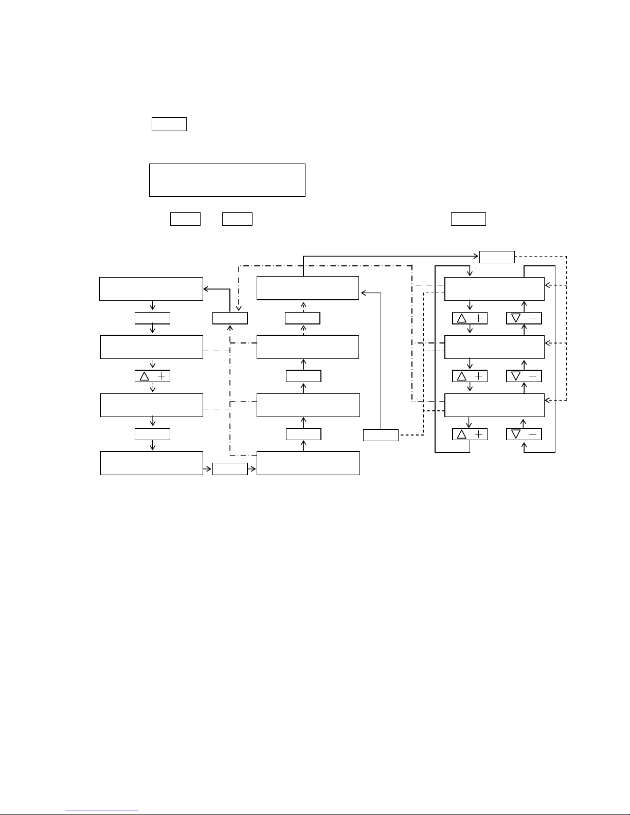
Chapter 1. Normal / Maintenance mode
1.Maintenance mode
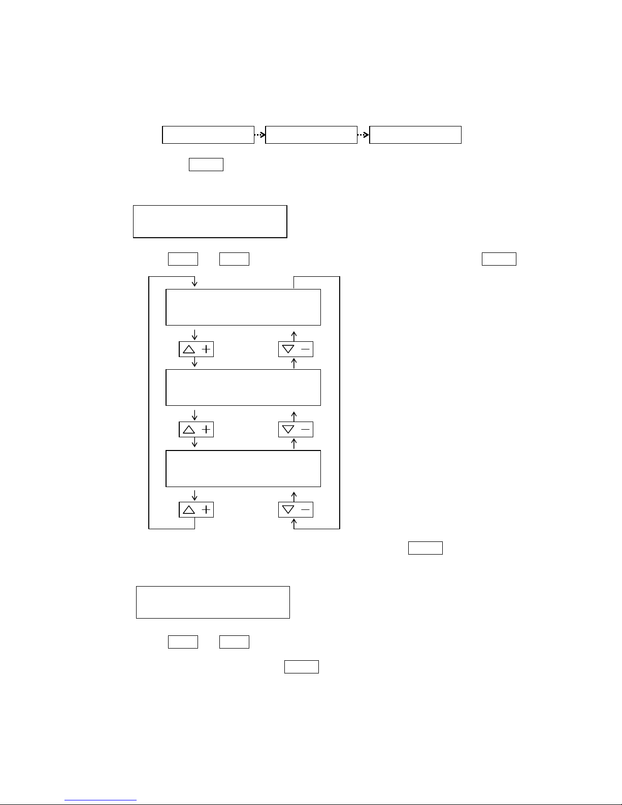
How to access the maintenance mode.
(1)Press the ADJUST
ADJUSTADJUST
ADJUST key. The LCD display becomes ready condition for adjusting mode.
(2)Press the △△△△ ++++ or ▽▽▽▽ ---- key and select the "
ADJUST MODE 99
…………““““
(3)Press ENTER
ENTERENTER
ENTER key. The LCD display become PASSWORD mode.
(4)Input the password
PT500A :
→ → →
PT500D:
→ → →
SUB AUTO:
→ → →
(5)Press ENTER
ENTERENTER
ENTER key after input the password. Software mode is changed Normal to Maintenance mode.
Note)When you selected the Maintenance mode, you can use all operation in Normal mode and
maintenance mode.
ADJUST MODE 99
…
MAINTENANCE MODE
MAINTENANCE MODE
PASSWORD [ ]
OPERATION
MODE
RATE
RADIUS
SPEED
RUDDER
LIMIT
RUDDER
LIMIT
RUDDER
LIMIT
OPERATION
MODE
OFF CRS
ALARM
RUDDER
LIMIT
RUDDER
LIMIT
OFF CRS
ALARM
RUDDER
LIMIT
MAINTENANCE 1
…
MAINTENANCE MODE
Page 6

1-2
SM80B22M02
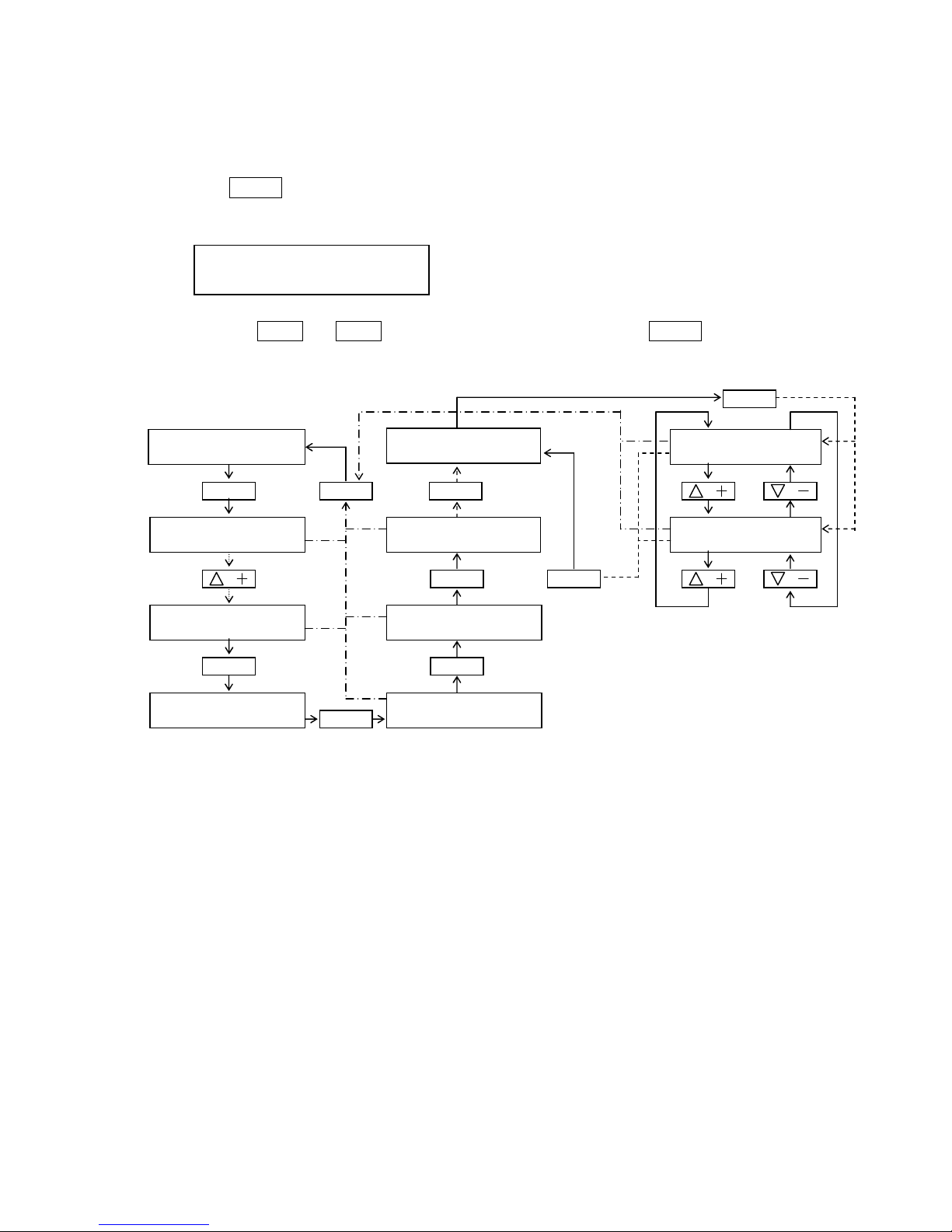
2.Normal mode(Release the maintenance mode)
Normal mode means to prohibit the maintenance mode
(1)Press the △△△△ ++++ or ▽▽▽▽ ---- key when the maintenance mode is selected.
In case of the PT500A type, you select the "
MAINTENANCE 19
… "
In case of the PT500D and SUBAUTO type, you select the "
MAINTENANCE 17
… "
PT500A: PT500D・SUBAUTO:
(2)Press ENTER
ENTERENTER
ENTER key. Software mode is changed to Normal mode
Note)The maintenance mode is automatically released by selecting the normal mode or when the
operator has kept the condition without key operation more than 1 hours.
MAINTENANCE 19
…
MAINTENANCE OFF
MAINTENANCE 17
…
MAINTENANCE OFF
ADJUST MODE 99
…
MAINTENANCE OFF
Page 7
1-3
SM80B22M02E
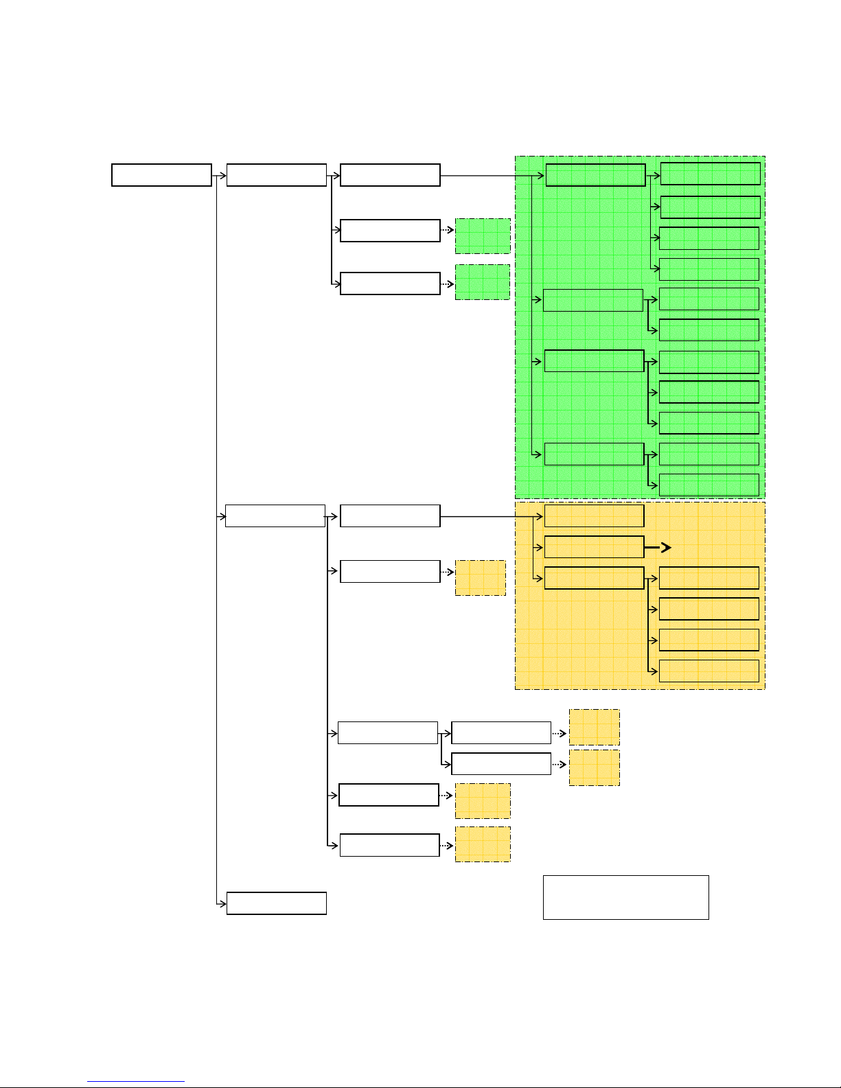
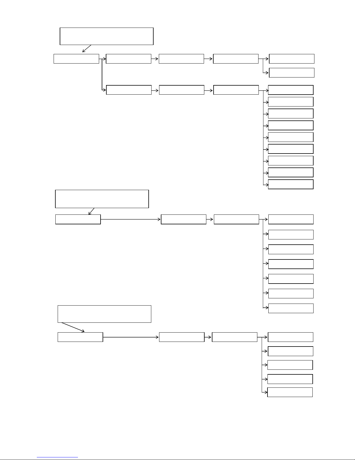
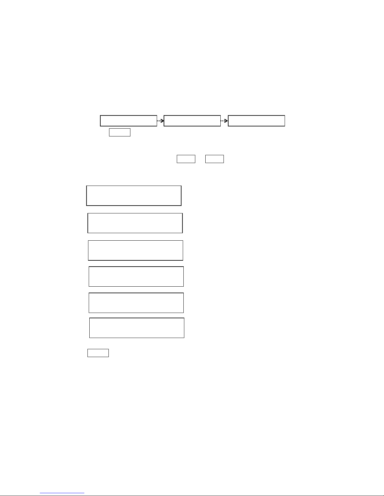
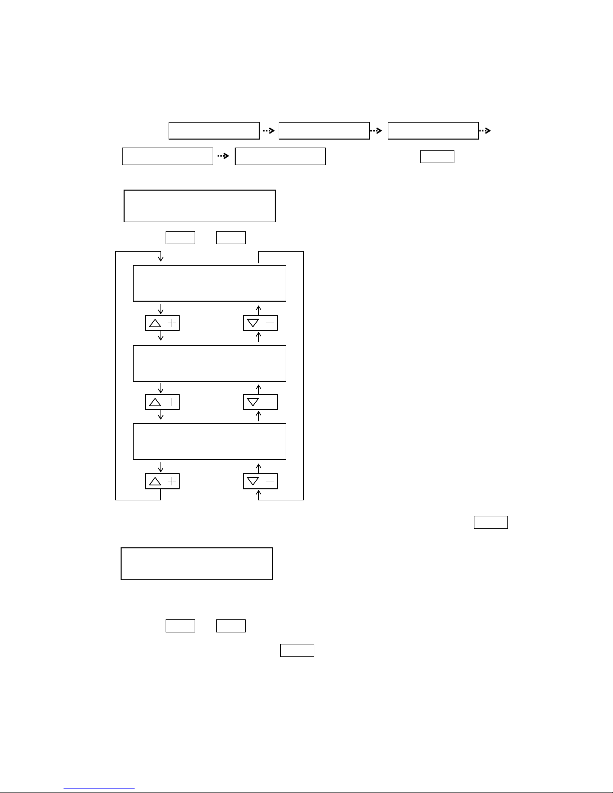
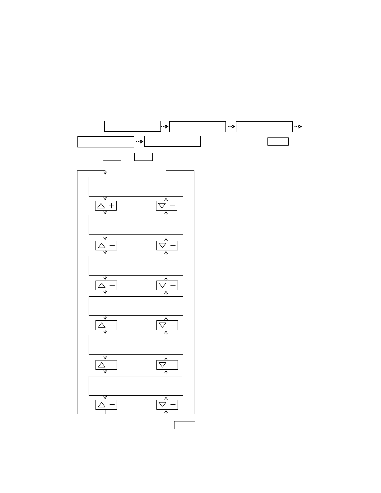
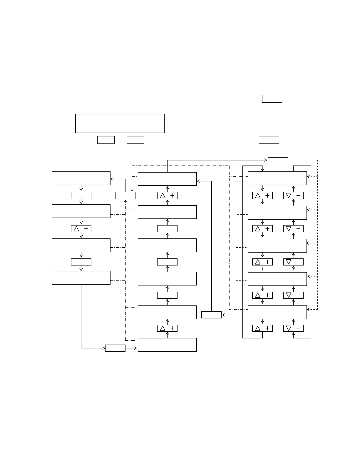
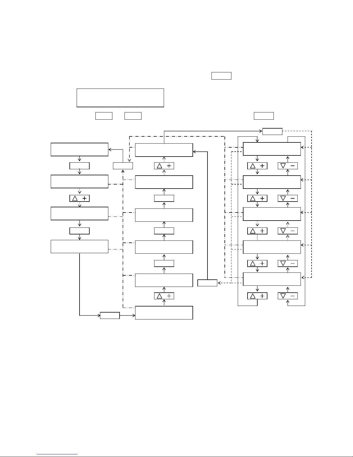
3.Selection of the maintenance mode
(1)Display the
"MAINTENACE 1
… "on the data display then Press the ENTER
ENTERENTER
ENTER key.
The data display is displayed I/F SET-UP mode.
(2)You can change the each maintenance item by pressing the △△△△ ++++ or ▽▽▽▽ ---- key.
PT500A:
①⇔②⇔③⇔④⇔⑤⇔⑥⇔⑦⇔⑧⇔⑨⇔⑩⇔⑪⇔⑫⇔⑬⇔⑭⇔⑮⇔⑯⇔⑰⇔⑱⇔⑲⇔①
①
⑪
②
⑫
③
⑬
④
⑭
⑤
⑮
⑥
⑯
⑦
⑰
⑧
⑱
⑨
⑲
⑩
Press ENTER
ENTERENTER
ENTER key after you selected the maintenance number. Then the maintenance function become valid
mode .
MAINTENANCE 19
…
MAINTENANCE OFF
MAINTENANCE 18
…
Special Data
MAINTENANCE 17
…
Option Set
MAINTENANCE 16
…
LINK-SLAVE DATA
MAINTENANCE 15
…
OVERRIDE COURSE
MAINTENANCE 14
…
KEY CLICK SW
MAINTENANCE 8
…
PROGRAM VERSION
MAINTENANCE 7
…
ADC POINT DISP
MAINTENANCE 6
…
CDV OUT
MAINTENANCE 5
…
RDA OUT
MAINTENANCE 4
…
AUTO RUDDER OUT
MAINTENANCE 13
…
BARGRAPH SW
MAINTENANCE 12
…
OFFCRS ALARM SW
MAINTENANCE 11
…
IDENT. DISP
MAINTENANCE 3
…
MEM ACCESSS-FLX
MAINTENANCE 2
…
MEM ACCESSS-FIX
MAINTENANCE 1
…
I/F SET-UP
MAINTENAN
CE 9
…
PROG.COLD START
MAINTENANCE 10
…
SHIP PARA. CALC
Page 8
1-4
SM80B22M02
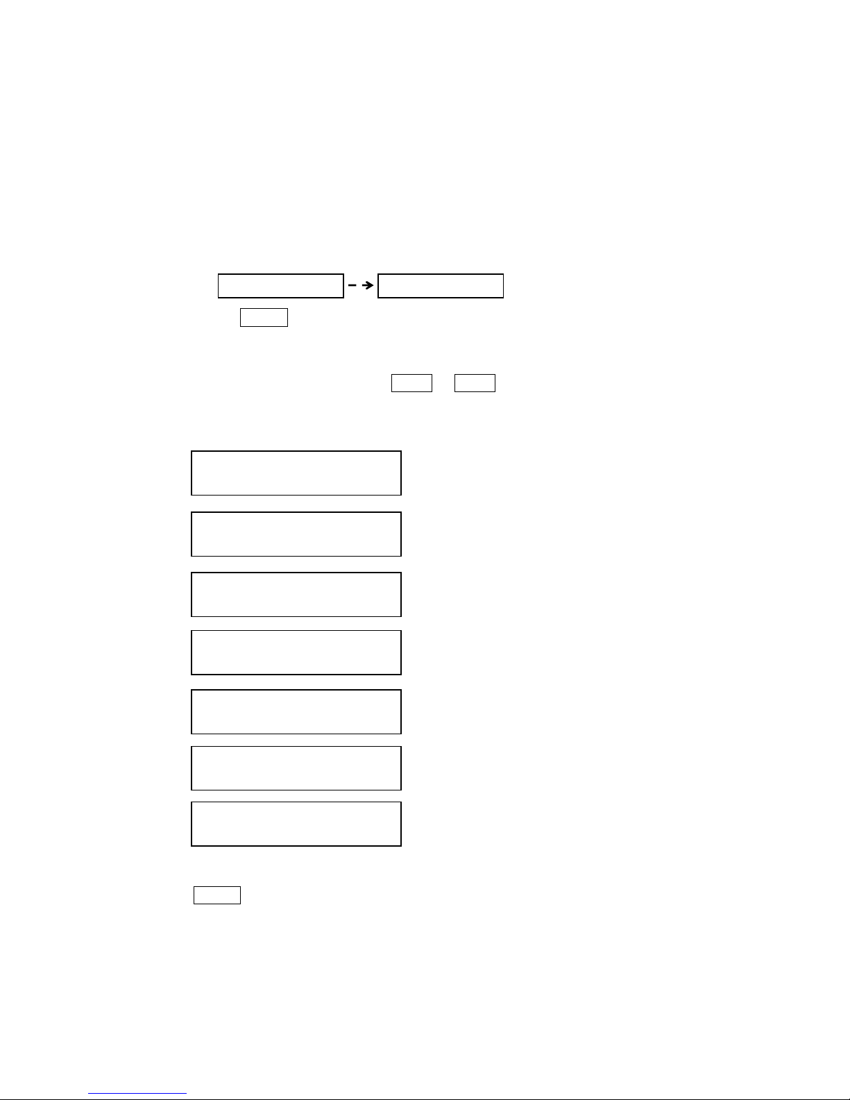
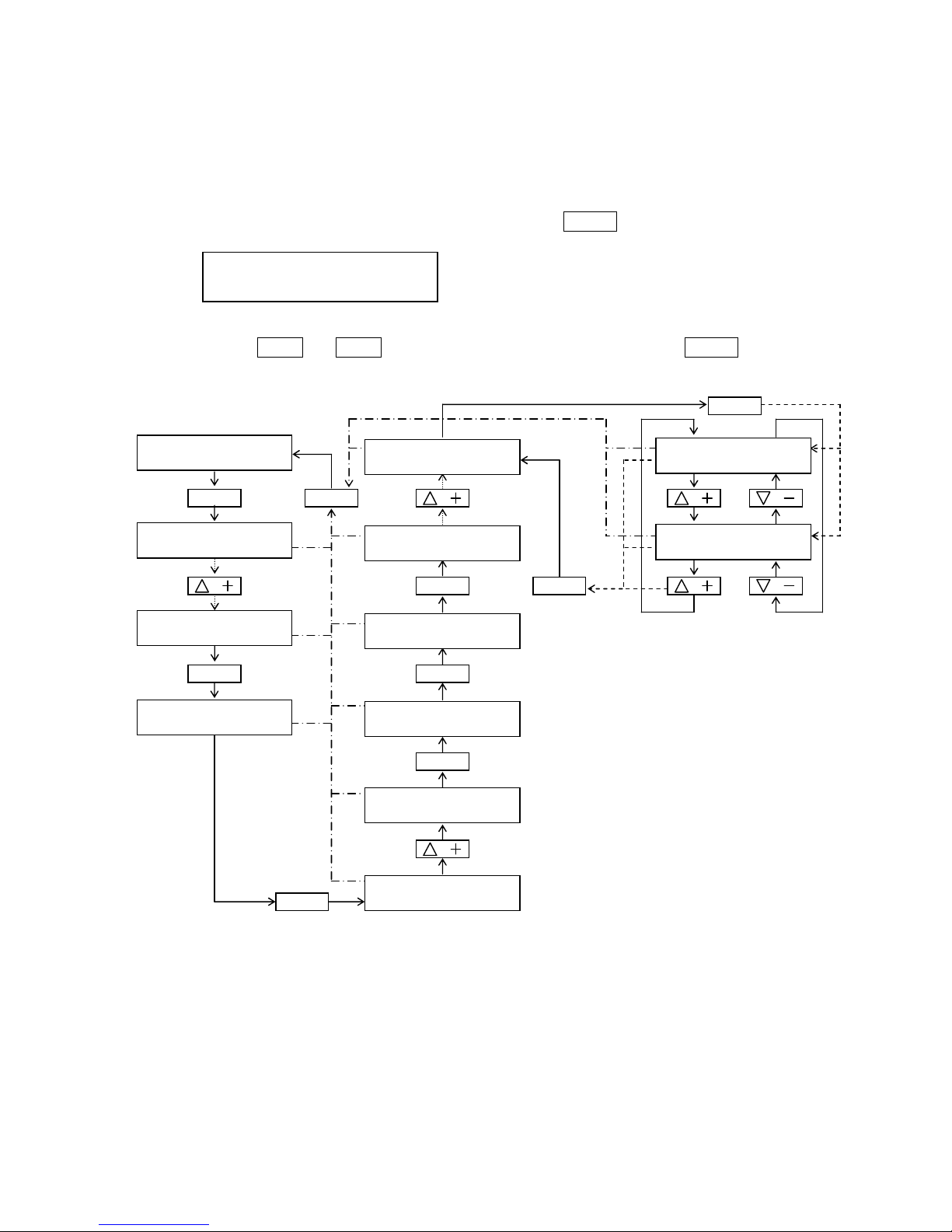
PT500D・SUBAUTO:
①⇔②⇔③⇔④⇔⑤⇔⑥⇔⑦⇔⑧⇔⑨⇔⑩⇔⑪⇔⑫⇔⑬⇔⑭⇔⑮⇔⑯⇔⑰⇔①
①
⑪
②
⑫
③
⑬
④
⑭
⑤
⑮
⑥
⑯
⑦
⑰
⑧
⑨
⑩
Press ENTER
ENTERENTER
ENTER key after you selected the maintenance number. Then the maintenance function become valid
mode .
MAINTENANCE 10
…
OFFCRS ALARM SW
MAINTENANCE 9
…
PROG.COLD START
MAINTENANCE 17
…
MAINTENANCE OFF
MAINTENANCE 16
…
Special Data
MAINTENANCE 15
…
Option Set
MAINTENANCE 14
…
LINK-SLAVE DATA
MAINTENANCE 13
…
OVERRIDE COURSE
MAINTENANCE 12
…
KEY CLICK SW
MAINTENANCE 8
…
PROGRAM VERSION
MAINTENANCE 7
…
ADC POINT DISP
MAINTENANCE 6
…
CDV OUT
MAINTENANCE 5
…
RDA OUT
MAINTENANCE 4
…
AUTO RUDDER OUT
MAINTENANCE 11
…
BARGRAPH SW
MAINTENANCE 3
…
MEM ACCESSS-FLX
MAINTENANCE 2
…
MEM ACCESSS-FIX
MAINTENANCE 1
…
I/F SET-UP
Page 9

2-1
SM80B22M02E
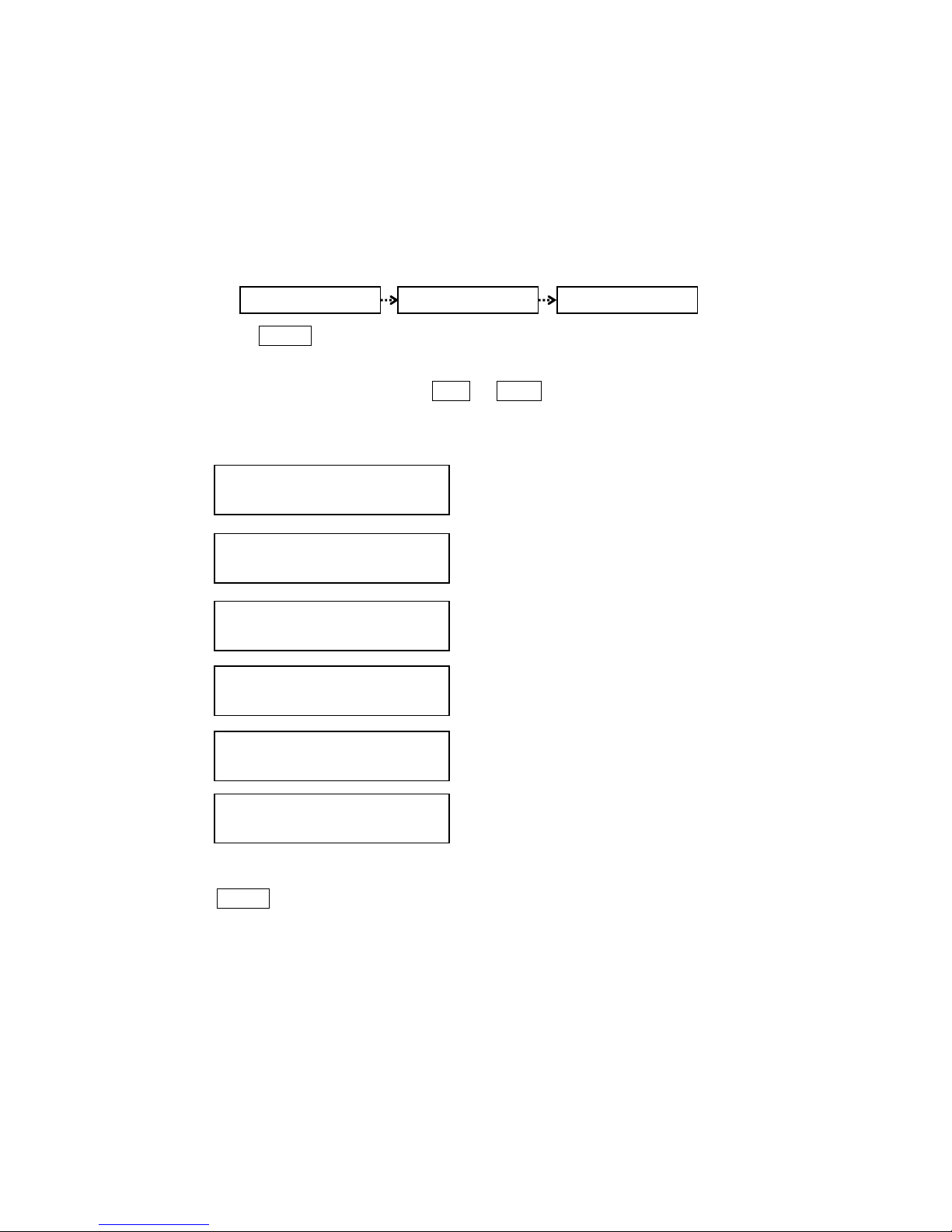
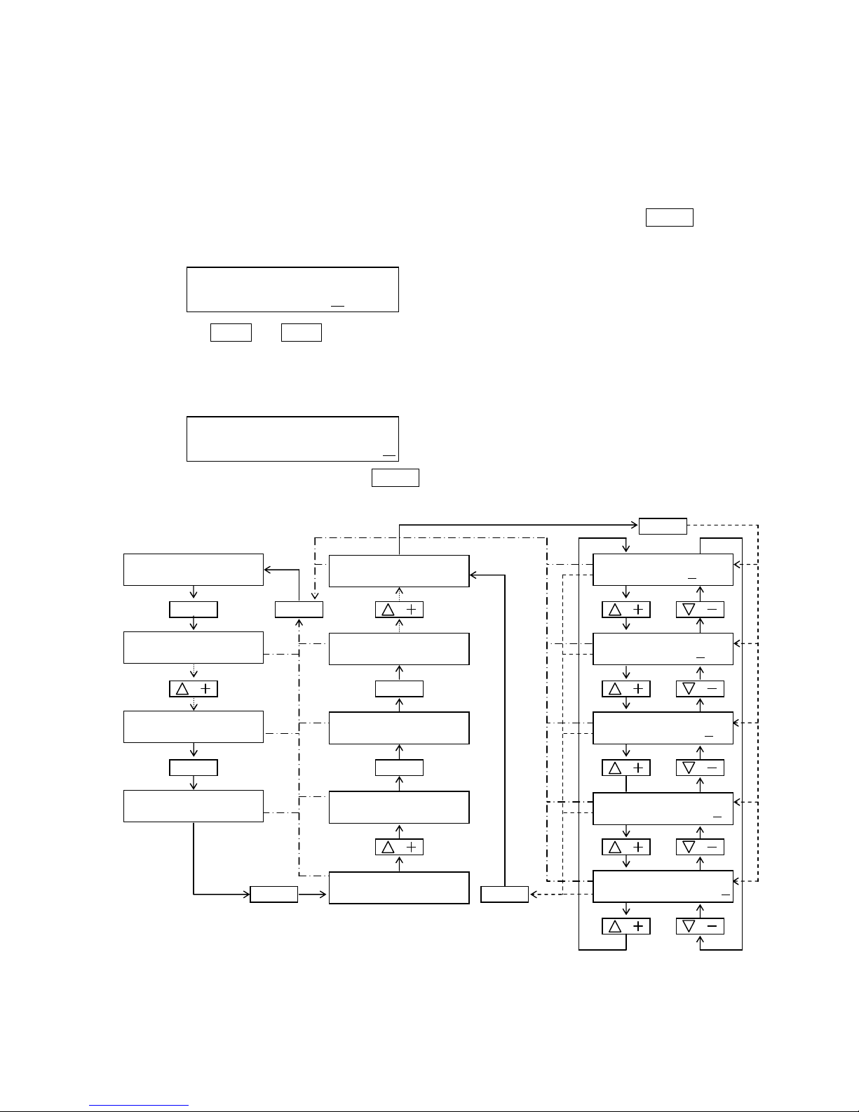
Chapter 2 I/F SET-UP
Set the protocol of the each input and output serial ports for corresponding with each equipment.
Setting items is as follows.
NOTE
In case of you changed
In case of you changed In case of you changed
In case of you changed setting item, please carry out the settlement of
setting item, please carry out the settlement of setting item, please carry out the settlement of
setting item, please carry out the settlement of ③③③③ I/F SET
I/F SET I/F SET
I/F SET----UP
UPUP
UP....
① Hardware setting(Set the Protocol)
② Software setting (Set the input and output condition)
③ Settlement of I/F set-up
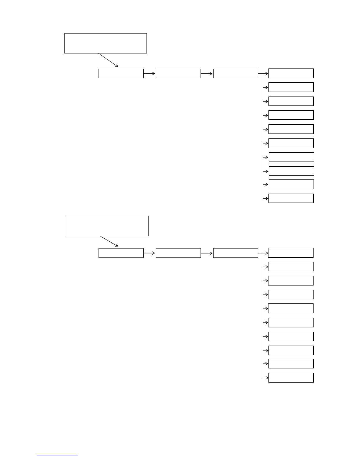
1. Select the I/F set-up data
(1) Press the ENTER
ENTERENTER
ENTER key after displayed "
MAINTENANCE 1 …
"on the data display.
The data display is displayed I/F SET-UP mode.
(2) Press △△△△ ++++ or ▽▽▽▽ ---- key to change the item.
①⇔②⇔③⇔④⇔①
①
Set the protocol of each setting port
②
Set the input /output condition of each setting port
③
Settlement of the data inputs
④
Press ENTER
ENTERENTER
ENTER key after selected the item. The function of the item becomes valid mode.
Please refer to the tree of I/F SET-UP
I/F SET
-
UP
…
HARDWARE SET
I/F SET
-
UP
…
SOFTWARE SET
I/F SET
-
UP
…
SET-UP DATA FIX
I/F SET
-
UP
…
<EXIT>
Page 10
2-2
SM80B22M02E
Refer to
Item①
①①①①
②②②②
Refer to
Item②
<The tree of the I/F SET-UP>
MAINTENANCE 1
…
I/F SET-UP
I/F SET
-
UP
…
HARDWARE SET
I/F HARD SET
-UP…
PORT= GYRO
GYRO HARD
…
BAUD RATE= ####
GYRO HARD
BAUD RATE= 1200
GYRO HARD
BAUD RATE= 2400
GYRO HARD
BAUD RATE= 4800
GYRO HARD
BAUD RATE= 9600
I/F HARD SET
-UP…
PORT= AUX.COMP
I/F SET
-
UP
…
SET-UP DATA FIX
I/F HARD SET
-UP…
PORT= INS/GPS
GYRO HARD
…
DATA BITS = #
GYRO HARD
…
DATA BITS = 7
GYRO HARD
…
DATA BITS = 8
GYRO HARD
…
PARITY = aaaa
GYRO HARD
…
PARITY = None
GYRO HARD
…
PARITY = Even
GYRO HARD
…
PARITY = Odd
GYRO HARD
…
STOP BITS = #
GYRO HARD
…
STOP BITS = 1
GYRO HARD
…
STOP BITS = 2
I/F SOFT SET
-UP…
PORT= GYRO
I/F SOFT SET
-UP…
PORT= AUX.COMP
I/F SET
-
UP
…
SOFTWARE SET
GYRO COMP. SOFT
…
FORMAT= NONE
GYRO COMP. SOFT
…
FORMAT= EXIT
GYRO COMP. SOFT
…
FORMAT= NEW
GYRO NEW
…
ADDRESS= $aaaaa
GYRO NEW
…
START POS.= #
GYRO NEW
…
INTERVAL= ##.#s
GYRO NEW
…
CHECK SUM = aaa
I/F SOFT SET
-UP…
PORT= INS/GPS INP
I/F SOFT SET
-UP…
PORT= INS/GPS OUT
I/G INP SOFT
…
XTE
I/G INP SOFT
…
SET COURSE
Set the current format
(Refer to next page)
③③③③
③③③③
Refer to
Item①
Refer to
Item②
Refer to
Item②
Refer to
Item②
I/F SOFT SET
-UP…
PORT= LOG
Refer to
Item②
Page 11
2-3
SM80B22M02E
GYRO EXIST
…
=aaaaaaaaaaaaaaa
GYRO COMP. SOFT
…
FORMAT= EXIST
I/F SOFT SET
-UP…
PORT= GYRO
Setting of the Gyrocompass
input format
AUX.COMP. EXIST
…
=aaaaaaaaaaaaaaa
AUX.COMP. EXIST
…
FORMAT= EXIST
I/F SOFT SET
-UP…
PORT= AUX.COMP
Setting of the Aux. compass
input format
GYRO5EXIST
12345
…
=NMEA6HEHDT23456
GYRO5EXIST
12345
…
=NMEA6xxHDT23456
GYRO5EXIST
12345
…
=NMEA6HDT0&2ROT6
GYRO5EXIST
12345
…
=YOKOGAWA0HEHRC6
GYRO5EXIST
12345
…
=NMEA6xxHDG23456
GYRO5EXIST
12345
…
=NMEA6HCHDT23456
GYRO5EXIST
12345
…
=NMEA6xxHDM23456
GYRO5EXIST
12345
…
=NUNOTANI:$HCHDM
GYRO5EXIST
12345
…
=NUNOTANI:$HCHRC
GYRO5EXIST
12345
…
=NAVIGAT-2100456
AUX.COMP.
0
EXIST
…
=NMEA6HEHDT23456
AUX.COMP.
0
EXIST
…
=NMEA6xxHDT23456
AUX.COMP.
0
EXIST
…
=NMEA6HDT0&2ROT6
AUX.COMP.
0
EXIST
…
=YOKOGAWA0HEHRC6
AUX.COMP.
0
EXIST
…
=NMEA6xxHDG23456
AUX.COMP.
0
EXIST
…
=NMEA6HCHDT23456
AUX.COMP.
0
EXIST
…
=NMEA6xxHDM23456
AUX.COMP.
0
EXIST
…
=NUNOTANI:$HCHDM
AUX.COMP.
0
EXIST
…
=NUNOTANI:$HCHRC
AUX.COMP.
EXIST
…
=NAVIGAT-2100456
Page 12
2-4
SM80B22M02E
Setting of the INS/GPS output
format
Setting of the LOG input (serial)
format
I/F SOFT SET
-UP…
PORT=INS/GPS INP
Setting of the INS/GPS input
format
XTE4INP8
EXIST
45…
=xxXTE7&9Mode456
XTE4INP8EXIST
45…
=xxXTE7890123456
XTE INP EXIST
…
=aaaaaaaaaaaaaaa
XTE INP SOFT
…
FORMAT= EXIST
I/G INP SOFT
…
XTE
SETC. INP EXIST
…
=NMEA0183:$xxHSC
SETC. INP EXIST
…
=INS-1
SETC. INP EXIST
…
=JRC5CAT-B&C3456
SETC. INP EXIST
…
=INS-27(Type3A)6
SETC. INP EXIST
…
=aaaaaaaaaaaaaaa
SETCRS INP SOFT
…
FORMAT= EXIT
I/G INP SOFT
…
SET COURSE
SETC. INP EXIST
…
=Super Bridge
SETC. INP EXIST
…
=Furuno8CAT-B456
SETC. INP EXIST
…
=Transas9CAT-C56
SETC. INP EXIST
…
=Kelvin8INS-1456
SETC. INP EXIST
…
=Tokimec90123456
I/G OUT EXIST
…
=$AGHTD(JRC)
I/G OUT EXIST
…
=$AGHTD(Furuno)
I/G OUT EXIST
…
= $AGDRR
I/G OUT EXIST
…
=aaaaaaaaaaaaaaa
I/G OUT SOFT
…
FORMAT= EXIT
I/F SOFT SET
-UP…
PORT=INS/GPS OUT
I/G OUT EXIST
…
=$AGHTD & $AGDRR
I/G OUT EXIST
…
=$AGHTD(Transas)
I/G OUT EXIST
…
=$AGHTD(Kelvin)
I/G OUT EXIST
…
=$AGHTD(Tokimec)
LOG EXIST
…
=NMEA xxVHW
LOG EXIST
…
=NMEA xxVBW (W)
LOG SOFT EXIST
…
=aaaaaaaaaaaaaaa
LOG SOFT
…
FORMAT= EXIT
I/F SOFT SET
-UP…
PORT= LOG
LOG EXIST
…
=NMEA xxVBW (G)
LOG EXIST
…
=YOKOGAWA VMVSD
LOG EXIST
…
=NMEA xxVTG
Page 13

2-5
SM80B22M02E
2. Hardware setting
Set the protocol for Gyro compass and Auxiliary compass ,INS/GPS.
Setting item is as follows.
① Hardware setting of the Gyrocompass
② Hardware setting of the Auxiliary compass
③ Hardware setting of the INS/GPS
④ Hardware setting of the LOG
(1)Set the ,then press ENTER
ENTERENTER
ENTER key.
Data display becomes a Hardware setting ready mode for each input port.
(2)Change the setting mode by using the △△△△ ++++ or ▽▽▽▽ ---- Keys.
①⇔②⇔③⇔④⇔⑤⇔⑥⇔①
①
Set the protocol of the Gyro compass port.
②
Set the protocol of the Auxiliary compass port.
③
Set the protocol of the INS/GPS port.
④
Set the protocol of the LOG port.
⑤
Back to the previous mode.
⑥
Back to the I/F setup top menu mode.
Press the ENTER
ENTERENTER
ENTER key after you selected the setting mode. It become the each protocol setting mode .
I/F HARD SET
-
UP
…
PORT= GYRO
I/F HARD SET
-
UP
…
PORT= AUX.GYRO
I/F HARD SET
-
UP
…
PORT= INS/GPS
MAINTENANCE 1 …
I/F SET-UP
MAINTENANCE 1 …
I/F SET-UP
I/F HARD SET
-
UP
…
PORT= [PREV]
I
/F HARD SET
-
UP
…
PORT= [TOP]
I/F HARD SET
-
UP
…
PORT= LOG
Page 14
2-6
SM80B22M02E
2.1 Hardware setting of the Gyrocompass
Set the protocol of the Gyrocompass. Setting item is as follows.
①Baud rate
②Length of the character
③Parity check
④Length of the stop bit
(1)Set the mode,
then press ENTER
ENTERENTER
ENTER key.
Data display becomes a Hardware setting ready mode for Gyrocompass protocol port.
(2)Change the setting mode by using the △△△△ ++++ or ▽▽▽▽ ---- key.
①⇔②⇔③⇔④⇔⑤⇔⑥⇔①
①
Baud rate
②
Length of the character
③
Parity check
④
Length of the stop bit
⑤
Back to the previous mode.
⑥
Back to the I/F setup top menu mode.
Press the ENTER
ENTERENTER
ENTER key after you selected the setting mode. It become the each protocol setting mode .
MAINTENANCE 1
…
I/F SET-UP
I/F SET
-
UP …
HARDWARE SET
I/F HARD
SET
-UP…
PORT= GYRO
GYRO HARD
…
BAUD RATE = ####
GYRO HARD
…
DATA BITS = #
GYRO HARD
…
PARITY = aaaa
GYRO HARD
…
STOP BITS = #
GYRO HARD
…
[PREV]
GYRO HARD
…
[TOP]
Page 15
2-7
SM80B22M02E
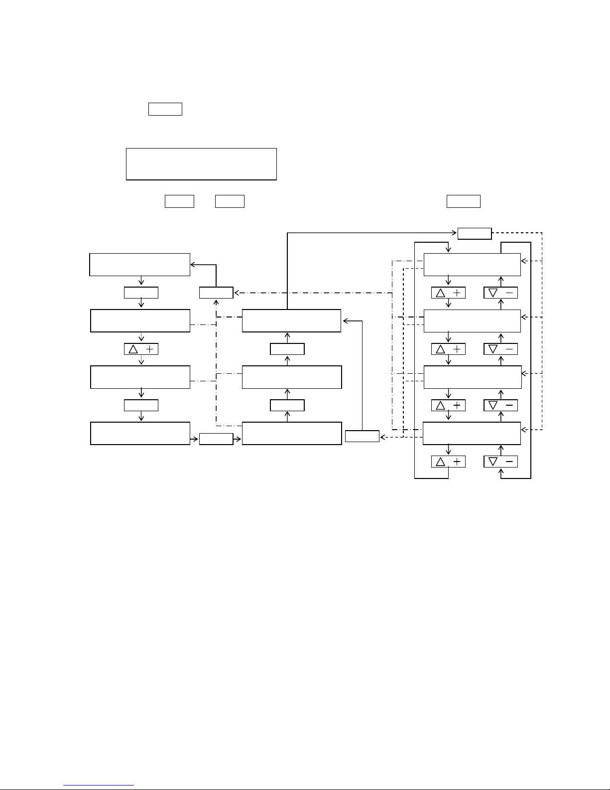
2.1.1 Baud rate
(1)Press ENTER
ENTERENTER
ENTER key when it is displayed the "
BAUD RATE = ####
" on the data display.
Data display become under setting mode.
(2)Press the △△△△ ++++ or ▽▽▽▽ ---- key to select the baud rate value. Then press ENTER
ENTERENTER
ENTER key.
SP D A UTO 13 . 5 k t
HE ADI NG- G 2 3 5. 8 ˆ
AD JUS T MO D E 1
…
DI MME R/C O NT R AS
AD J UST M ODE
99 …
MA INT ENA N CE MO D E
MA INT ENA N CE 1
…
I/ F S ET- U P
GY RO HAR D
…
BA UD RA T E = X XXX
I/ F H ARD SE T
-
UP …
PO RT = G YR O
I / F S ET
-
UP
…
HA RDW ARE SE T
GY RO HAR D
BA UD R AT E < 12 0 0
GY RO HAR D
BA UD R AT E < 24 0 0
GY RO HAR D
BA UD R A TE < 48 0 0
GY RO HAR D
BA UD R A TE < 96 0 0
ADJUST
ENTER
ENTER
ENTER
ADJUST
ENTER
ENTER
ENTER
GYRO HARD
BAUD RATE < 2400
Page 16
2-8
SM80B22M02E
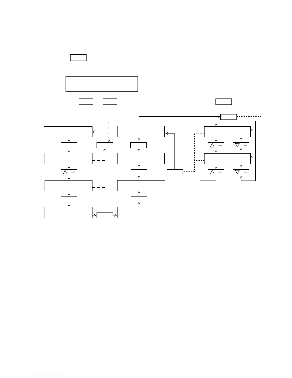
2.1.2 Length of the character
(1)Press ENTER
ENTERENTER
ENTER key when it is displayed the "
DATA BITS = #
" on the data display.
Data display become under setting mode.
(2)Press the △△△△ ++++ or ▽▽▽▽ ---- key to select the character length. Then press ENTER
ENTERENTER
ENTER key.
GYRO HARD
DATA BITS < 7
SP D A UTO 13 . 5 k t
HE ADI NG- G 2 3 5. 8 ˆ
AD JUS T MO D E 1
…
DI MME R/C O NT R AS
AD J UST M ODE
99 …
MA INT ENA N CE MO D E
MA INT ENA N CE 1
…
I/ F S ET- U P
GY RO HAR D
…
BA UD RA T E = # ###
I/ F H ARD SE T
-
UP …
PO RT = G YR O
I / F S ET
-
UP
…
HA RDW ARE SE T
GY RO HAR D
DA TA B I TS < 7
GY RO HAR D
DA TA B I TS < 8
ADJUST
ENTER
ENTER
ENTER
ADJUST
ENTER
ENTER
ENTER
GY RO HAR D
…
DA TA BIT S = #
ENTER
Page 17
2-9
SM80B22M02E
2.1.3 Parity check
(1)Press ENTER
ENTERENTER
ENTER key when it is displayed the "
PARITY = aaaa
" on the data display.
Data display become under setting mode.
(2)Press the △△△△ ++++ or ▽▽▽▽ ---- key to select the parity check. Then press ENTER
ENTERENTER
ENTER key.
GYRO HARD
PARITY < None
SP D A UTO 13 . 5 k t
HE ADI NG- G 2 3 5. 8 ˆ
AD JUS T MO D E 1
…
DI MME R/C O NT R AS
AD J UST M ODE
99 …
MA INT ENA N CE MO D E
MA INT ENA N CE 1
…
I/ F S ET- U P
GY RO HAR D
…
BA UD RA T E = # ###
I/ F H ARD SE T
-
UP …
PO RT = G YR O
I / F S ET
-
UP
…
HA RDW ARE SE T
GY RO HAR D
PA RIT Y < N one
GY RO HAR D
PA RIT Y < E ven
ADJUST
ENTER
ENTER
ENTER
ADJUST
ENTER
ENTER
ENTER
GY RO HAR D
…
PA RIT Y = a aa a
ENTER
GY RO HAR D
PA RIT Y < Odd
Page 18
2-10
SM80B22M02E
2.1.4 Stop bit
(1)Press ENTER
ENTERENTER
ENTER key when it is displayed the "
STOP BITS = #"
on the data display.
The data display become under setting mode.
(2)Press the △△△△ ++++ or ▽▽▽▽ ---- key to select the stop bit. Then press ENTER
ENTERENTER
ENTER key.
GYRO HARD
STOP BITS < 1
SP D A UTO 13 . 5 k t
HE ADI NG- G 2 3 5. 8 ˆ
AD JUS T MO D E 1
…
DI MME R/C O NT R AS
AD J UST M ODE
99 …
MA INT ENA N CE MO D E
MA INT ENA N CE 1
…
I/ F S ET- U P
GY RO HAR D
…
BA UD RA T E = # ###
I/ F H ARD SE T
-
UP …
PO RT = G YR O
I/ F SE T
-
UP
…
HA RDW ARE SE T
GY RO HAR D
ST OP B I TS < 1
GY RO HAR D
ST OP B I TS < 2
ADJUST
ENTER
ENTER
ENTER
ADJUST
ENTER
ENTER
ENTER
GY RO HAR D
…
ST OP BIT S = #
ENTER
Page 19

2-11
SM80B22M02E
2.2 Hardware setting of the Auxiliary compass
Set the protocol of the Auxiliary compass. Setting item is as follows.
①Baud rate
②Length of the character
③Parity check
④Length of the stop bit
(1)Set the mode.
Then press ENTER
ENTERENTER
ENTER key.
Data display becomes a Hardware setting ready mode for Auxiliary compass protocol port.
(2)Change the setting mode by using the △△△△ ++++ or ▽▽▽▽ ---- Keys.
①⇔②⇔③⇔④⇔⑤⇔⑥⇔①
①
Baud rate
②
Length of the character
③
Parity check
④
Length of stop bit
⑤
Back to the previous mode.
⑥
Back to the I/F setup top menu mode.
Press the ENTER
ENTERENTER
ENTER key after you selected the setting mode. It become the each protocol setting mode .
Following setting item is the same as Gyrocompass hardware setting
Refer to Gyrocompass hardware setting.
MAINTENANCE 1
…
I/F SET-UP
I/F SET
-
UP …
HARDWARE SET
I/F HARD SET
-UP…
PORT= AUX.COMP
AUX. COMP. HARD
…
BAUD RATE = ####
AUX. COMP. HARD
…
DATA BITS = #
AUX. COMP. HARD
…
PARITY = aaaa
AUX. COMP. HARD
…
STOP BITS = #
AUX. COMP. HARD
…
[PREV]
AUX. COMP.
HARD
…
[TOP]
Page 20
2-12
SM80B22M02E
2.3 Hardware setting of the INS/GPS
Set the protocol of the INS/GPS. Setting item is as follows.
①Baud rate
②Length of the character
③Parity check
④Length of the stop bit
(1)Set the mode.
Then press ENTER
ENTERENTER
ENTER key.
Data display becomes a Hardware setting ready mode for INS/GPS protocol port.
(2)Change the setting mode by using the △△△△ ++++ or ▽▽▽▽ ---- Keys.
①⇔②⇔③⇔④⇔⑤⇔⑥⇔①
①
Baud rate
②
Length of the character
③
Parity check
④
Length of stop bit
⑤
Back to the previous mode.
⑥
Back to the I/F setup top menu mode.
Press the ENTER
ENTERENTER
ENTER key after you selected the setting mode. It become the each protocol setting mode .
Following setting item is the same as Gyrocompass hardware setting
Refer to Gyrocompass hardware setting.
MAINTENANCE 1
…
I/F SET-UP
I/F SET
-
UP …
HARDWARE SET
I/F HARD SET
-UP…
PORT= INS/GPS
INS/GPS HARD
…
BAUD RATE = ####
INS/GPS HARD
…
DATA BITS = #
INS/GPS HARD
…
PARITY = aaaa
INS/GPS HARD
…
STOP BITS = #
INS/GPS HARD
…
[PREV]
INS/GPS HARD
…
[TOP]
Page 21

2-13
SM80B22M02E
2.3 Hardware setting of the LOG
Set the protocol of the LOG. Setting item is as follows.
①Baud rate
②Length of the character
③Parity check
④Length of the stop bit
(1)Set the mode.
Then press ENTER
ENTERENTER
ENTER key.
Data display becomes a Hardware setting ready mode for LOG protocol port.
(2)Change the setting mode by using the △△△△ ++++ or ▽▽▽▽ ---- Keys.
①⇔②⇔③⇔④⇔⑤⇔⑥⇔①
①
Baud rate
②
Length of the character
③
Parity check
④
Length of stop bit
⑤
Back to the previous mode.
⑥
Back to the I/F setup top menu mode.
MAINTENANCE 1
…
I/F SET-UP
I/F SET
-
UP …
HARDWARE SET
I/F HARD SET
-UP…
PORT= LOG
LOG HARD
…
BAUD RATE = ####
LOG HARD
…
DATA BITS = #
LOG HARD
…
PARITY = aaaa
LOG HARD
…
STOP BITS = #
LOG HARD
…
[PREV]
LOG HARD
…
[TOP]
Page 22
2-14
SM80B22M02E
3. Software setting
Set the protocol for Gyro compass input and Auxiliary compass input , INS/GPS input and output.
Setting item is as follows.
① Software setting of the Gyrocompass input
② Software setting of the Auxiliary compass input
③ Software setting of the INS/GPS input
④ Software setting of the INS/GPS output
⑤ Software setting of the LOG input
(1)Set the key.
Then press ENTER
ENTERENTER
ENTER key.
Data display become a Hardware setting ready mode for each inputting port.
(2)Change the setting mode by using the △△△△ ++++ or ▽▽▽▽ ---- Keys.
①⇔②⇔③⇔④⇔⑤⇔⑥⇔⑦⇔①
①
Set the Input signal of the Gyrocompass data
②
Set the Input signal of the Auxiliary compass data
③
Set the Input signal of the INS/GPS data
④
Set the output signal of the INS/GPS data
⑤
Set the Input signal of the LOG data
⑥
Back to the previous mode.
⑦
Back to the I/F setup top menu mode.
Press the ENTER
ENTERENTER
ENTER key after you selected the setting mode. It become the each protocol setting mode .
MAINTENANCE
1 …
I/F SET-UP
I/F SET
-
UP …
SOFTWARE SET
I/F SOFT SET
-UP…
PORT= GYRO
I/F SOFT SET
-UP…
PORT= AUX.COMP
I/F SOFT SET
-UP…
PORT=INS/GPS INP
I/F SOFT SET
-UP…
PORT=INS/GPS OUT
I/F SOFT SET
-UP…
[PREV]
I/F SOFT SET
-UP…
[TOP]
I/F SOFT SET
-UP…
PORT=LOG INP
Page 23
2-15
SM80B22M02E
3.1 Software setting of the Gyrocompass input
Set the input data of the Gyrocompass data
(1)Set the mode.
Then press the ENTER
ENTERENTER
ENTER key.
Display the current setting item for Gyrocompass heading data on the Data display.
(2)Press the △△△△ ++++ or ▽▽▽▽ ---- key to select the Gyrocompass format. Then press ENTER
ENTERENTER
ENTER key.
(3)In case of you change the input data. Back to(1)item , then Press ENTER
ENTERENTER
ENTER key.
Data display become under setting mode
(4)Press the △△△△ ++++ or ▽▽▽▽ ---- key. Alter the display,
NONE
⇔
EXIST
⇔
NEW
⇔
NONE
.
After selected the setting mode , Press ENTER
ENTERENTER
ENTER key..
If you choose the
EXIST
or
NEW mode, move to the 3.1.1 or 3.1.2 setting item.
GYRO SOFT
…
FORMAT = EXIST
MAINTENANCE 1
…
I/F SET-UP
I/F SET
-
UP …
SOFTWARE SET
I/F SOFT SET
-UP…
PORT= GYRO
GYRO SO
FT
…
FORMAT = EXIST
GYRO SOFT
…
[PREV]
GYRO SOFT
…
[TOP]
GYRO SOFT
…
FORMAT < aaaaa
Page 24
2-16
SM80B22M02E
3.1.1 Set the existing gyrocompass heading input format
(1)Set the
mode. Then press ENTER
ENTERENTER
ENTER key/
Display the current existing format on the data display.
(2)Press the △△△△ ++++ or ▽▽▽▽ ---- key to select the existing Gyrocompass format.
(3)In case of you choose the existing gyrocompass format. Back to(1)item , then Press ENTER
ENTERENTER
ENTER key.
The data display become under setting mode
The part of a....a is displayed setting condition.
Refer the contents to next page.
(4)Press the △△△△ ++++ or ▽▽▽▽ ---- key. Alter the display of the existing format.
After selected the setting mode , Press ENTER
ENTERENTER
ENTER key..
GYRO
EXIST
…
=
HEHDT
MAINTENANCE 1
…
I/F SET-UP
I/F SET
-
UP …
SOFTWARE SET
I/F SOFT SET
-UP…
PORT= GYRO
GYRO SOFT
…
FORMAT = aaaaa
GYRO SOFT
…
FORMAT < EXIST
GYRO EXIST
…
= HEHDT
GYRO EXIST
<aaaaaaaaaaaaaaa
GYRO
EXIST
…
= [PREV]
GYRO
EXIST
…
= [TOP]
Page 25

2-17
SM80B22M02E
Selection Data Contents
NMEA HEHDT NMEA0183
$HEHDT (Taker ID should be only “HE”.)
Check-sum is required.
NMEA xxHDT NMEA0183
$xxHDT (Taker ID “xx” is not checked)
Check-sum is required.
NMEA HDT&ROT NMEA0183
$xxHDT and $xxROT messages are required.
(Taker ID “xx” is not checked)
Check-sum is required.
YOKOGAWA HEHRC CMZ300X format
$HEHRC/$HCHRC
(The name was changed to YOKOGAWA HEHRC.)
NMEA xxHDG NMEA0183
$xxHDG (Taker ID “xx” is not checked)
Check-sum is required.
NMEA HCHDT NMEA0183
$HCHDT (Taker ID should be only “HC”.)
Check-sum is required.
NMEA xxHDM NMEA0183
$xxHDM (Taker ID “xx” is not checked)
Check-sum is not required.
NUNOTANI:$HCHDM MUNOTANI’s TMC format
$HCHDM(Taker ID should be only “HC”.)
Check-sum is required.
NUNOTANI:$HCHRC MUNOTANI’s TMC format
$HCHRC(Taker ID should be only “HC”.)
Check-sum is required.
NAVIGAT-2100 NAIGAT-2100 format
-$HEHDT(GYRO) or $HCHDT(MAG)
-$HEROT
Heading and ROT data are used.
When $HEHDT is received, the data is used as GYRO input.
When $HCHDT is received, the data is used as Magnet input.
Page 26
2-18
SM80B22M02E
3.1.2 New format setting of the gyrocompass heading format
Setting item is as follows.
① Reception Header
② Position of the input field
③ Check sum Valid/Invalid
④ Transmission data output interval
3.1.2.1 Select the GYRO SOFT FORMAT<NEW
(1)Set the
mode. Then press the ENTER
ENTERENTER
ENTER key.
(2)Press the △△△△ ++++ or ▽▽▽▽ ---- key to select the setting item.
After selected the setting mode , Press ENTER
ENTERENTER
ENTER key..
MAINTENANCE 1
…
I/F SET-UP
I/F SET
-
UP …
SOFTWARE SET
I/F SOFT SET
-UP…
PORT= GYRO
GYRO SOFT
…
FORMAT = aaaaa
GYRO SOFT
…
FORMAT < NEW
GYRO NEW
…
START POS.= #
GYRO NEW
…
ADDRESS = $aaaaa
GYRO NEW
…
CHECK SUM = aaaa
GYRO NEW
…
INTERVAL=##.#sec
GYRO NEW
…
[PREV]
GYRO NEW
…
[TOP]
Page 27
2-19
SM80B22M02E
3.1.2.2 Setting of the reception header
Set the reception header
The Header consists of five character from $ to reception discrimination data.
(1) When you are displayed "ADDRESS = $aaaaa" on the data display ,then press ENTER
ENTERENTER
ENTER key.
The data display become under setting mode.
←Cursor position is inputting point
(2)Press △△△△ ++++ or ▽▽▽▽ ---- key to set the cursor point. Then change the data by turning the Set
course dial. Turn to the clockwise direction , data is increased and turn to the counter
clockwise direction ,data is decreased. (Data is A to Z alphabet)
(3)After input the header , then press ENTER
ENTERENTER
ENTER key.
ADJUST
ENTER
ENTER
ENTER
ADJUST
ENTER
ENTER
ENTER
GYRO NEW
ADDRESS < $AAAAA
GYRO NEW
ADDRESS < $GPABC
AD J UST M ODE
99 …
MA INT ENA N CE MO D E
MA INT ENA N CE 1
…
I/ F S ET- U P
AD J UST M O DE
1 …
DI MME R/C O NT R AS T
SP D A UTO 13 . 5 K t
HE ADI NG- G 2 3 5. 8 ˆ
GY RO NEW
…
AD DRE SS = $ a aa a a
GY RO SO FT
…
FO RMA T = NE W
I/ F S OFT S E T
-
UP
…
PO RT = GYRO
I/ F S ET
-
UP
…
SO FTW ARE SE T
I/ F SE T
-
UP
…
HA RDW ARE SE T
GY RO NEW
…
AD DRE SS < $ A AA A A
GY RO NEW
…
AD DRE SS < $ A AA A A
GY RO NEW
…
AD DRE SS < $ A AA A A
GY RO NEW
…
AD DRE SS < $ A AA A A
GY RO NEW
…
AD DRE SS < $ A AA A A
Page 28
2-20
SM80B22M02E
3.1.2.3 Setting of the data field position
Set the data field position of the reception data
Example)
”$ABCDE,123.3,456.7,890.1,234.5*”
In case of set the data field at“3”above text data ,reception data become “890.1”.
(1)When you displayed the "
START POS.= ##
" on the data display, press ENTER
ENTERENTER
ENTER key.
The data display become under setting mode.
(2)Press the △△△△ ++++ or ▽▽▽▽ ---- key to select the setting mode. Then press ENTER
ENTERENTER
ENTER key.
ADJ
UST ENTER
ENTER
ENTER
ADJUST
ENTER
ENTER
ENTER
ENTER
GYRO NEW
START POS.< 1
AD J UST M ODE
99 …
MA INT ENA N CE MO D E
MA INT ENA N CE 1
…
I/ F S ET- U P
AD J UST M O DE
1 …
DI MME R/C O NT R AS T
SP D A UTO 13 . 5 K t
HE ADI NG- G 2 3 5. 8 ˆ
GY RO NEW
…
AD DRE SS = $ a aa a a
GY RO SO FT
…
FO RMA T = NE W
I/ F S OFT S E T
-
UP
…
PO RT = GYRO
I/ F S ET
-
UP
…
SO FTW ARE SE T
I/ F SE T
-
UP
…
HA RDW ARE SE T
GY RO NEW
…
ST ART P O S. = ##
GY RO NEW
ST ART PO S .< 1
GY RO NEW
ST ART PO S .< 2
GY RO NEW
ST ART PO S .< 3
GY RO NEW
ST ART PO S .< 98
GY RO NEW
ST ART PO S .< 99
Page 29
2-21
SM80B22M02E
3.1.2.4 Set the valid /invalid condition of the check sum
Select the valid / invalid condition of the check sum
When occurred the check sum error as the valid condition , communication become no reception
condition.
(1)When displayed the "
CHECK SUM = aaaa
" , press ENTER
ENTERENTER
ENTER key.
The data display become under setting mode
(2)Press the △△△△ ++++ or ▽▽▽▽ ---- key to select the setting mode. Then press ENTER
ENTERENTER
ENTER key.
ADJUST
ENTER
ENTER
ENTER
ADJUST
ENTER
ENTER
ENTER
ENTER
GYRO NEW
CHECK SUM < WITH
AD J UST M ODE
99 …
MA INT ENA N CE MO D E
MA INT ENA N CE 1
…
I/ F S ET- U P
AD J UST M O DE
1 …
DI MME R/C O NT R AS T
SP D A UTO 13 . 5 K t
HE ADI NG- G 2 3 5. 8 ˆ
GY RO NEW
…
AD DRE SS = $ a aa a a
GY RO SO FT
…
FO RMA T = NE W
I/ F S OFT S E T
-
UP
…
PO RT = GYRO
I/ F S ET
-
UP
…
SO FTW ARE SE T
I/ F SE T
-
UP
…
HA RDW ARE SE T
GY RO NEW
…
CH ECK SU M = aa a a
GY RO NEW
…
CH ECK SU M < Wi t h
GY RO NEW
…
CH ECK SU M < No n e
Page 30
2-22
SM80B22M02E
3.1.2.5 Set the transmission data output interval
Time out of the reception data is selected the longer time value either 3 second or 3 times of the
data output interval time
(1)When displayed the "
INTERVAL= XX.Xsec
" , press ENTER
ENTERENTER
ENTER key.
The data display become under setting mode
(2)Press the △△△△ ++++ or ▽▽▽▽ ---- key to select the setting mode. Then press ENTER
ENTERENTER
ENTER key.
ADJUST
ENTER
ENTER
ENTER
ADJUST
ENTER
ENTER
ENTER
ENTER
GYRO NEW
INTERVAL<##.#sec
AD J UST M ODE
99 …
MA INT ENA N CE MO D E
MA INT ENA N CE 1
…
I/ F S ET- U P
AD J UST M O DE
1 …
DI MME R/C O NT R AS T
SP D A UTO 13 . 5 K t
HE ADI NG- G 2 3 5. 8 ˆ
GY RO NEW
…
AD DRE SS = $ a aa a a
GY RO SO FT
…
FO RMA T = NE W
I/ F S OFT S E T
-
UP
…
PO RT = GYRO
I/ F S ET
-
UP
…
SO FTW ARE SE T
I/ F SE T
-
UP
…
HA RDW ARE SE T
GY RO NEW
…
IN TER VAL = ## . #s e c
GY RO NEW
…
IN TER VAL < 0 . 1s e c
GY RO NEW
…
IN TER VAL < 0 . 2s e c
GY RO NEW
…
IN TER VAL < 0 . 3s e c
GY RO NEW
…
IN TER VAL < 19 . 0s e c
GY RO NEW
…
IN TER VAL < 20 . 0s e c
Page 31

2-23
SM80B22M02E
3.2 Software setting of the Auxiliary compass input
(1)Set the key.
Then press ENTER
ENTERENTER
ENTER key.
The data display become under setting mode
(2)Press the △△△△ ++++ or ▽▽▽▽ ---- key to select the setting item.
(3)In case of you choose the existing Aux. compass format. Back to(1)item , then Press ENTER
ENTERENTER
ENTER key.
The data display become under setting mode
(4)Press the △△△△ ++++ or ▽▽▽▽ ---- key. Alter the display “
NONE
⇔
EXIST
⇔
NEW
⇔
NONE”
After selected the setting mode , Press ENTER
ENTERENTER
ENTER key..
EXIST
and
NEW
setting item is the same as Gyrocompass software setting
Refer to 3.1 Soft ware setting of the Gyrocompass setting input .
MAINTENANCE 1
…
I/F SET-UP
I/F SET
-
UP …
SOFTWARE SET
I/F SOFT SET
-UP…
PORT= AUX.COMP
AUX. COMP SOFT
…
FORMAT = EXIST
AUX. COMP SOFT
…
FORMAT =
EXIST
AUX. COMP SOFT
…
[PREV]
AUX. COMP SOFT
…
[TOP]
AUX. COMP. SOFT
FORMAT < aaaaa
Page 32

2-24
SM80B22M02E
3.3 Software setting of the INS/GPS input
(1)Set the key.
Then press ENTER
ENTERENTER
ENTER key.
The data display become under setting mode
(2)Press the △△△△ ++++ or ▽▽▽▽ ---- key to select the setting item.
After selected the setting mode , Press ENTER
ENTERENTER
ENTER key..
I/G INP SOFT
…
XTE
I/G INP SOFT
…
XTE
I/G INP SOFT
…
[PREV]
I/G INP SOFT
…
[TOP]
I/G INP SOFT
…
SET COURSE
MAINTENANCE 1
…
I/F SET-UP
I/F SET
-
UP …
SOFTWARE SET
I/F SOFT SET
-UP…
PORT=INS/GPS INP
Page 33

2-25
SM80B22M02E
3.3.1 Software setting of the XTE input
(1)Set the
key. Then press ENTER
ENTERENTER
ENTER key.
The data display become under setting mode
(2)Press the △△△△ ++++ or ▽▽▽▽ ---- key to select the setting item.
(3)In case of you choose the existing format. Back to(1)item , then Press ENTER
ENTERENTER
ENTER key.
The data display become under setting mode
(4)Press the △△△△ ++++ or ▽▽▽▽ ---- key. Alter the display “
NONE
⇔
EXIST
⇔
NEW
⇔
NONE”
After selected the setting mode , Press ENTER
ENTERENTER
ENTER key..
XTE INP SOFT
…
FORMAT = EXIST
XTE INP SOFT
…
FORMAT =
EXIST
XTE INP SOFT
…
[PREV]
XTE INP SOFT
…
[TOP]
MAINTENANCE 1
…
I/F SET-UP
I/F SET
-
UP …
SOFTWARE SET
I/F SOFT SET
-UP…
PORT=INS/GPS INP
I/F SOFT SET
-UP…
XTE
XTE INP SOFT
…
FORMAT < aaaaa
Page 34

2-26
SM80B22M02E
3.3.2 Software setting of the XTE existing format
Set the NMEA0183 format of XTE (Cross track error)
(1)Set the
key. Then press ENTER
ENTERENTER
ENTER key.
The data display become under setting mode
(2)Press the △△△△ ++++ or ▽▽▽▽ ---- key to select the setting item.
In case of you choose the existing format. Back to(1)item , then Press ENTER
ENTERENTER
ENTER key.
The data display become under setting mode
The part of a....a is displayed setting condition.
Refer the contents to next page.
(4)Press the △△△△ ++++ or ▽▽▽▽ ---- key. Alter the display of the existing format.
After selected the setting mode , Press ENTER
ENTERENTER
ENTER key..
MAINTENANCE 1
…
I/F SET-UP
I/F SET
-
UP …
SOFTWARE SET
I/F SOFT SET
-UP…
PORT=INS/GPS INP
I/F SOFT SET
-UP…
XTE
XTE INP EXIST
…
=
XTE
MAINTENANCE 1
…
I/F SET-UP
I/F SET
-
UP …
SOFTWARE SET
XTE INP SOFT
…
=XTE
XTE INP SOFT
…
[PREV]
XTE INP SOFT
…
[TOP]
XTE INP EXIST
…
<aaaaaaaaaaaaaa
a
Page 35

2-27
SM80B22M02E
Selection Data Contents
xxXTE NMEA0183
$xxXTE (Taker ID “xx” is not checked)
Check-sum is required.
xxXTE & Mode NMEA0183 Ver. 2.30
$xxXTE (Taker ID “xx” is not checked)
Check-sum is required.
Mode indicator of XTE message is checked.
Page 36

2-28
SM80B22M02E
3.3.3 New format setting of the XTE format
Setting item is as follows.
① Reception Header
② Position of the input field
③ Check sum Valid/Invalid
④ Transmission data output interval
Setting item and a way is the same as Gyrocompass software setting
Refer to 3.1.2 Gyrocompass software setting.
Page 37

2-29
SM80B22M02E
3.3.4 Software setting of the Set course input format
(1)Set the
key. Then press ENTER
ENTERENTER
ENTER key.
The data display become under setting mode
(2)Press the △△△△ ++++ or ▽▽▽▽ ---- key to select the setting item.
(3)In case of you choose the existing format. Back to(1)item , then Press ENTER
ENTERENTER
ENTER key.
The data display become under setting mode
(4)Press the △△△△ ++++ or ▽▽▽▽ ---- key. Alter the display of the existing format.
After selected the setting mode , Press ENTER
ENTERENTER
ENTER key..
MAINTENANCE 1
…
I/F SET-UP
I/F SET
-
UP …
SOFTWARE SET
I/F SOFT SET
-UP…
PORT=INS/GPS INP
I/F SOFT SET
-UP…
SET COURSE
SETCRS
INP SOFT
…
FORMAT = EXIST
SETCRS INP SOFT
…
[PREV]
SETCRS INP SOFT
…
[TOP]
SETCRS INP SOFT
…
FORMAT = EXIST
SETCRS INP SOFT
FORMAT < aaaaa
Page 38

2-30
SM80B22M02E
3.3.5 Set the set course input of the existing format
(1)Set the
keys. Then press ENTER
ENTERENTER
ENTER key.
The data display become under setting mode
(2)Press the △△△△ ++++ or ▽▽▽▽ ---- key to select the setting item.
(3)In case of you choose the existing format. Back to(1)item , then Press ENTER
ENTERENTER
ENTER key.
The data display become under setting mode
The part of a....a is displayed setting condition.
Refer the contents to next page.
(4)Press the △△△△ ++++ or ▽▽▽▽ ---- key. Alter the display of the existing format.
After selected the setting mode , Press ENTER
ENTERENTER
ENTER key.
MAINTENANCE 1
…
I/F SET-UP
I/F SET
-
UP …
SOFTWARE SET
I/F SOFT SET
-UP…
PORT=INS/GPS INP
I/G INP SOFT
…
SET COURSE
SETCRS INP SOFT
…
FORMAT = aaaaa
SETCRS INP SOF
T…
FORMAT < EXIST
SETC. INP EXIST
…
=
NMEA 0183:$xxHSC
SETC. INP EXIST
…
=
NMEA 0183:$xxHSC
SETC. INP EXIST
…
[PREV]
SETC. INP
EXIST
…
[TOP]
SETC. INP EXIST
<aaaaaaaaaaaaaaa
Page 39

2-31
SM80B22M02E
Selection data Contents
NMEA 0183:$xxHSC $xxHSC (Taker ID “xx” is not checked)
The first field data is used as the set course data.
The second field data should be “T”.
Super Bridge
For MITSUBISHI super bridge I/F
$xxTRC format
Taker ID “xx” should be either EC, EI, II or IN.
INS-1
For interfacing with ECDIS made by JRC
(Correspondence to a style approval previous ATOS version)
① $xxHTC
② $xxXTE
Taker ID “xx” should be either EC, EI, II or IN.
JRC CAT-B&C
(for MED TCS
(for MED TCS (for MED TCS
(for MED TCS
type approval
type approvaltype approval
type approval))))
For interfacing with ECDIS made by JRC
The following four(4) messages are required.
① $xxHTC
② $xxXTE (set by XTE setting)
③ $xxHSC
④ $xxVDR
Taker ID “xx” should be either EC, EI, II or IN.
INS-2 (Type A) For interfacing with ECDIS made by FURUNO (At present, not
used.)
$xxHTC
Taker ID “xx” should be either EC, EI, II or IN.
Furuno CAT-B
(for MED TCS
(for MED TCS (for MED TCS
(for MED TCS
type approval
type approvaltype approval
type approval))))
For interfacing with ECDIS made by FURUNO
The following two(2) messages are required.
① $xxHTC
② $xxVTG
Taker ID “xx” should be either EC, EI, II or IN.
Transas CAT-C
(for MED TCS
(for MED TCS (for MED TCS
(for MED TCS
type approval
type approvaltype approval
type approval))))
For interfacing with ECDIS made by TRANSAS
$xxHTC
Taker ID “xx” should be either EC, EI, II or IN.
Kelvin INS-1 For interfacing with ECDIS made by KELVIN HUGHES
The following two(2) messages are required.
$xxHTC
Taker ID “xx” should be either EC, EI, II or IN.
Tokimec For interfacing with ECDIS made by TOKIMEC
$xxHTC
Taker ID “xx” should be either EC, EI, II or IN.
Page 40

2-32
SM80B22M02E
3.3.6 New format setting of the set course format
Setting item is as follows.
① Reception Header
② Position of the input field
③ Check sum Valid/Invalid
④ Transmission data output interval
Setting item and way is the same as Gyrocompass software setting
Refer to 3.1.2 Gyrocompass software setting.
Page 41

2-33
SM80B22M02E
3.4 Software setting of the INS/GPS output
Set theINS/GPS output specification
(1)Set the key.
Then press ENTER
ENTERENTER
ENTER key.
The data display become under setting mode
(2)Press the △△△△ ++++ or ▽▽▽▽ ---- key to select the setting item.
(3)In case of you change the input data. Back to(1)item , then Press ENTER
ENTERENTER
ENTER key.
The data display become under setting mode
(4)Press the △△△△ ++++ or ▽▽▽▽ ---- key. Alter the display “
NONE
⇔
EXIST
⇔
NEW
⇔
NONE”
After selected the setting mode , Press ENTER
ENTERENTER
ENTER key..
Note ) NEW setting is not available. It is not able to access to NEW.
I/G OUT SOFT
…
FORMAT = EXIST
I/G OUT SOFT
[PREV]
I/G OUT SOFT
[TOP]
MAINTENANCE 1
…
I/F SET-UP
I/F SET
-
UP …
SOFTWARE SET
I/F SOFT SET
-UP…
PORT=INS/GPS OUT
I/G OUT SOFT
…
FORMAT = EXIST
I/G OUT SOFT
…
FORMAT < EXIST
Page 42

2-34
SM80B22M02E
3.4.1 Software setting of the INS/GPS existing output format
(1)Set the
keys.
Then press ENTER
ENTERENTER
ENTER key.
The data display become under setting mode
(2)Press the △△△△ ++++ or ▽▽▽▽ ---- key to select the setting item.
(3)In case of you change the format. Back to(1)item , then Press ENTER
ENTERENTER
ENTER key.
The data display become under setting mode
The part of a....a is displayed setting condition.
Referto the contents to next page.
(4)Press the △△△△ ++++ or ▽▽▽▽ ---- key. Alter the display of the existing format.
After selected the setting mode , Press ENTER
ENTERENTER
ENTER key..
MAINTENANCE 1
…
I/F SET-UP
I/F SET
-
UP …
SOFTWARE SET
I/F SOFT SET
-UP…
PORT=INS/GPS OUT
I/G OUT SOFT
…
FORMAT = aaaaa
I/G OUT
SOFT
…
FORMAT < EXIST
I/G OUT EXIST
…
= $AGDRR
I/G OUT EXIST
…
[PREV]
I/G
OUT EXIST
…
[TOP]
I/G OUT EXIST
…
<aaaaaaaaaaaaaaa
I/G OUT EXIST
…
=
$
AGDRR
Page 43

2-35
SM80B22M02E
Data Contents
$AGDRR
123456789012345678901234567890123456
$AGDRR,axx.x,axx.x,axx.x,aa*hh<CR><LF>
8:Course deviation P=Port , S=Stbd
9..12:Course deviation(deg)
14:Rudder P=Port , S=Stbd
15..18:Rudder (deg)
20:Rate of turn P=Port , S=Stbd
21..24:Rate of turn(deg/min)
26:H=HAND mode , R=R/C , F=N.F. ,
C=Alter the course(AUTO) , K=Course keeping(AUTO) ,
O=Override
27:N=NOT NAVI , E=NAVI
29..30:Check sum
$AGHTD(JRC)
JRC ECDIS tracking format or VDR format
Send the 3 formats
(for TCS-B & C Type approval)
① $AGHTD format
② $AGRSA format
③ $PYDKS format
$AGHTD(Furuno)
FURUNO ECDIS comply with TCS interface format or VDR
(for TCS-B Type approval)
Send the 2 format
① $AGHTD format
② $AGRSA format
$AGHTD & $AGDRR
FURUNO ECDIS comply with Simplify tracking control or VDR
Send the following 3 format
① $AGHTD format
② $AGRSA format
③ $ AGDRR,axx.x,axx.x,axx.x,aa*hh<CR><LF>
(Refer to the above contents for detail information)
$AGHTD(Transas)
TRANSAS ECDIS interface format or VDR
(for TCS-C Type approval)
① $AGHTD format
② $AGRSA format
③ $PYDKD,CRA format (for INS)
$AGHTD(Kelvin)
KELVIN HUGHES ECDIS interface format or VDR
Send the 2 format
① $AGHTD format
② $AGRSA format
(It is during developing.)
$AGHTD(Tokimec)
TOKIMEC ECDIS interface format or VDR
Send the 2 format
① $AGHTD format
② $AGRSA format
Page 44

2-36
SM80B22M02E
3.5 Software setting of LOG input format
Set the input data of the LOG data
(1)Set the mode.
Then press the ENTER
ENTERENTER
ENTER key.
Display the current setting item for LOG data on the Data display.
(2)Press the △△△△ ++++ or ▽▽▽▽ ---- key to select the LOG format. Then press the ENTER
ENTERENTER
ENTER key.
(3)In case of you change the input data. Back to (1) item, Then press the ENTER
ENTERENTER
ENTER key.
Data display become under setting mode
(4)Press the △△△△ ++++ or ▽▽▽▽ ---- key. After the display,
NONE
⇔
EXIST
⇔
NEW
⇔
NONE
.
After selected the setting mode, press the ENTER
ENTERENTER
ENTER key.
If you choose the EXIST or NEW mode, move to the 3.5.1 or 3.5.2 setting item.
MAINTENANCE 1
…
I/F SET-UP
I/F SET
-
UP …
SOFTWARE SET
I/F SOFT SET
-UP…
PORT= LOG
LOG SOFT
…
FORMAT = EXIST
LOG SOFT
…
FORMAT =
EXIST
LOG SOFT
…
[PREV]
LOG
SOFT
…
[TOP]
LOG SOFT
…
FORMAT< aaaaa
Page 45

2-37
SM80B22M02E
3.5.1 Set the existing LOG input format
(1) Set the
mode. Then press the ENTER
ENTERENTER
ENTER key.
Display the current existing format on the data display.
(2)Press the △△△△ ++++ or ▽▽▽▽ ---- key to select the existing LOG format.
(3)In case of you change the existing LOG input data. Back to (1) item, Then press the ENTER
ENTERENTER
ENTER key.
The data display becomes under setting mode
The part of a….a is displayed setting condition.
Refer to the contents to next page.
(4)Press the △△△△ ++++ or ▽▽▽▽ ---- key. After the display, of the existing format.
After selected the setting mode, press the ENTER
ENTERENTER
ENTER key.
MAINTENANCE 1
…
I/F SET-UP
I/F SET
-
UP …
SOFTWARE SET
I/F SOFT SET
-UP…
PORT= LOG
LOG SOFT
…
FORMAT = aaaaa
LOG SOFT
…
FORMAT < EXIST
LOG EXIST
…
=NMEA xxVBW (W)
LOG
EXIST
…
=NMEA xxVBW (W)
LOG
EXIST
…
= [PREV]
LOG
EXIST
…
= [TOP]
LOG EXIST
<aaaaaaaaaaaaaaa
Page 46

2-38
SM80B22M02E
Selection Data Contents
NMEA xxVBW(W)
(speed through the water : STW)
NMEA0183
$xxVBW (Taker ID “xx” is not checked)
Check-sum is required.
Fore-Aft STW speed is used. The data valid status is checked.
NMEA xxVHW
(speed through the water : STW)
NMEA0183
$xxVHW (Taker ID “xx” is not checked)
Check-sum is required.
The speed data is used. The status of [kt] is checked.
YOKOGAWA VMVSD
(speed through the water : STW)
EML201 format
$VMVSD (The name was changed to YOKOGAWA VMVSD.)
NMEA xxVBW(G)
(speed over the ground : SOG)
NMEA0183
$xxVBW (Taker ID “xx” is not checked)
Check-sum is required.
Fore-Aft SOG speed is used. The data valid status is checked.
NMEA xxVTG
(speed over the ground : SOG)
NMEA0183
$xxVTG (Taker ID “xx” is not checked)
Check-sum is required.
The speed data is used. The status of [kt] is checked.
Page 47

2-39
SM80B22M02E
3.5.2 New format setting of the LOG input format
Setting item is as follows;
① Reception Header
② Position of the input field
③ Check sum Valid/Invalid
④ Transmission data output interval
Setting item and way is the same as Gyrocompass software setting
Refer to 3.1.2 Gyrocompass software setting.
Page 48

2-40
SM80B22M02E
Page 49

3-1
SM80B22M02E
Chapter 3 Memory access-FIX (1 bite)
This is the function for changing the contents in the RAM. You can change the contents and address
number in the RAM by inputting the HEX code
The data of the display is refreshed every 1 second.
(1)Select the "
MAINTENANCE 2 …
" mode on the data display. Then press ENTER
ENTERENTER
ENTER key.
The data display become under setting mode.
←Cursor position is inputting point
(2)Press △△△△ ++++ or ▽▽▽▽ ---- key to alter the cursor position. Then change the address by turning the
course setting dial .
Turn to the clockwise the course setting dial, data is increased . Turn to the counterclockwise it ,data is
decreased. (HEX data is from o to F.)
←Data is changed by course setting dial.
(3)Press ENTER
ENTERENTER
ENTER key. Display the contents of the address
(4)Press △△△△ ++++ or ▽▽▽▽ ---- key to alter the cursor position. Then change the data by turning the course
setting dial .
Turn to the clockwise the course setting dial, data is increased . Turn to the counterclockwise it ,data is
decreased. (HEX data is from o to F.)
(5)Press ENTER
ENTERENTER
ENTER key, data is refreshed .
Note 1) It is not possible to refresh the data except the RAM, Backup RAM,NVRAM.
Note 2) When you change the some contents, it has potential that the program become hang-up
Note 3) You couldn’t change the I/O Device data.
Note 4) It is not possible to refresh the data when you pressed the ENTER
ENTERENTER
ENTER key only.
ADDRESS=
0
12DF5
FIX[AA] = AA
Flicker the data every 1 second
ADDRESS<
0
12DF
5
FIX[ ] =
ADDRESS=
0
12DF5
FIX[AA] = 84
ADDRESS<
012DF5
FIX[84] = 84
ADDRESS<
000000
FIX[ ] =
Page 50

Page 51

4-1
SM80B22M02E
Chapter 4 Memory Access-FLX(4bite)
This is the function for changing the contents in the RAM. You can change the contents and address
number in the RAM by inputting the HEX code
(1)Select the "
MAINTENANCE 3 …
" mode on the data display. Then press EN
ENEN
ENTER
TERTER
TER key.
The data display become under setting mode.
←Cursor position is inputting point
(2)Press △△△△ ++++ or ▽▽▽▽ ---- key to alter the cursor position. Then change the address by turning the
course setting dial .
Turn to the clockwise the course setting dial, data is increased . Turn to the counterclockwise it ,data is
decreased. (HEX data is from o to F.)
←Data is changed by course setting dial.
(3)Press ENTER
ENTERENTER
ENTER key. Display the contents of the address
(4)Press △△△△ ++++ or ▽▽▽▽ ---- key to alter the cursor position. Then change the data by turning the course
setting dial .
Turn to the clockwise the course setting dial, data is increased . Turn to the counterclockwise it ,data is
decreased. (HEX data is from o to F.)
(5)Press ENTER
ENTERENTER
ENTER key, data is refreshed .
Note 1) It is not possible to refresh the data except the RAM, Backup RAM,NVRAM.
Note 2) When you change the some contents, it has potential that the program become hang-up
Note 3) In case of you change the real number value, it is necessary to change the floating point style.
Note 4) It is not possible to refresh the data when you press the only ENTER
ENTERENTER
ENTER key.
ADDRESS<
0
0000
0
FIX = [ ]
ADDRESS<
0
12DF
5
FIX = [ ]
12DF5=[3E99
999A]
FIX < 00000000
12DF5=[3E99
999A]
FIX < 3E12345F
ADDRESS<
0
12DF
5
FIX = [ ]
Page 52

Page 53

5-1
SM80B22M02E
Chapter 5 DAC Output
Output the rudder value based on the DAC and display the Rudder feedback angle value at every 0.5
second. Output value can select the Rudder angle (
P45~S45)
or DAC value
(0~
FFF).
The actual control routine is bypassed under this operation.
(1)
Select the "
MAINTENANCE 4 …
" mode on the data display. Then press
ENTER
ENTERENTER
ENTER
key.
Rudder output become Mid ship position.
The data display become under setting mode.
(2)
Press
△△△△ ++++
or
▽▽▽▽ ----
key to alter the cursor position.
①⇔②⇔③⇔①
①
←
DAC value input
②
←
Rudder value
③
(3)
Select the AUTO RUDDER OUT of DAC value input, then press the
ENTER
ENTERENTER
ENTER
key.
The data display become under setting mode.
←
Cursor position is inputting point
(4)
Press
△△△△ ++++
or
▽▽▽▽ ----
key to alter the cursor position. Then change the address by turning the
course setting dial .
Turn to the clockwise the course setting dial, data is increased . Turn to the counterclockwise it ,data is
decreased. (HEX data is from o to F.)
←
Cursor position is inputting point
(5)
Press
ENTER
ENTERENTER
ENTER
key. Rudder order from the DAC value shall be supplied.
←
Cursor position is inputting point
Rudder feedback
angle
Rudder angle
(P45~S45)
DAC
value
(0h~FFFh)
AUTO RUDDER OUT
=[800] 0 a###.#
AUTO RUDDER OUT
=[800] 0 a###.#
AUTO RUDDER OUT
= 800[ 0]S###.#
AUTO RUDDER OUT
= <EXIT>
AUTO RUDDER OUT
<[800] 0 a###.#
AUTO RUDDER OUT
<[CB0] 0 a###.#
AUTO RUDDER OUT
=[CB0]P30 a###.#
Page 54

5-2
SM80B22M02E
(6)
Press
△△△△ ++++
or
▽▽▽▽ ----
key to select the AUTO RUDDER OUT. Then press
ENTER
ENTERENTER
ENTER
key.
The data display become under setting mode.
←
Rudder value
(7)
Press
△△△△ ++++
or
▽▽▽▽ ----
key ,the data increase and decrease.
Press
ENTER
ENTERENTER
ENTER
key after setting the data. Then auto steering unit outputs the rudder value.
ADC
value
MSB LSB
HEX
Voltage
[V]
Rudder
Value
[°]
111111111111 0xFFF
111111111110 0xFFE
111111010000 0xFD0
+5.0 S 50.0
100000000001 0x801
+0.0025 S 0.025
100000000000 0x800
0.0 0.0
011111111111 0x7FF
-0.0025 P 0.025
000000110000 0x030
-5.0 P 50.0
000000000001 0x001
000000000000 0x000
AUTO RUDDER OUT
< 800[ 0] a###.#
AUTO RUDDER OUT
< 418[S25] a###.#
Page 55

6-1
SM80B22M02E
Chapter 6 Actual rudder angle output
Output the DAC value based on rudder order
The actual control routine is bypassed under this operation.
(1)
Select the "
MAINTENANCE 5 …
" mode on the data display. Then press
ENTER
ENTERENTER
ENTER
key.
①
(2)
Press
△△△△ ++++
or
▽▽▽▽ ----
key to alter the item
①⇔②⇔①
①
②
(3)
Select the RDA OUT , then press
ENTER
ENTERENTER
ENTER
key.
The data display become under setting mode.
(4)
Press
△△△△ ++++
or
▽▽▽▽ ----
key ,the data increase and decrease.
Press
ENTER
ENTERENTER
ENTER
key after setting the rudder value.
Then auto steering unit outputs the DAC value.
RDA OUT
…
= 0
RDA OUT
…
= 0
RDA OUT
…
= <EXIT>
RDA OUT
< 0
RDA OUT
< S33
Page 56

Page 57

7-1
SM80B22M02E
Chapter 7 Course deviation output
Output the DAC value based on course deviation value
The actual control routine is bypassed under this operation.
(1)
Select the "
MAINTENANCE 6 …
" mode on the data display. Then press
ENTER
ENTERENTER
ENTER
key.
①
(2)
Press
△△△△ ++++
or
▽▽▽▽ ----
key to alter the item
①⇔②⇔①
①
②
(3)
Select the CDV OUT , then press
ENTER
ENTERENTER
ENTER
key.
The data display become under setting mode.
(4)
Press
△△△△ ++++
or
▽▽▽▽ ----
key ,the data increase and decrease.
Press
ENTER
ENTERENTER
ENTER
key after setting the course deviation value.
Then auto steering unit outputs the DAC value.
RDA OUT
…
= 0
CDV OUT
…
= 0
CDV OUT
…
= <EXIT>
CDV OUT
< 0
CDV OUT
< P22
Page 58

Page 59

8-1
SM80B22M02E
Chapter 8 Display of the analogue input
Display the ADC value of the each analogue input
ADC value is refreshed every 0.5 second .
(1))
Select the "
MAINTENANCE 7 …
" mode on the data display. Then press
ENTER
ENTERENTER
ENTER
key.
①
←
ADCValue
(2)
Press
△△△△ ++++
or
▽▽▽▽ ----
key to alter the item
①⇔②⇔③⇔④⇔⑤⇔⑥⇔⑦⇔⑧⇔①
(3)
Point number
A-1:No.1
Rudder feedback angle
A-2:No.1
Rudder order value
A-3:No.2
Rudder feedback value
A-4:No.2
Rudder order value
A-5:No.3
Rudder feedback value
A-6:No.3
Rudder order value
A-7:No.4
Rudder feedback value
A-8:No.4
Rudder order value
(
Note
)ADC
value is 0.10/deg = 40
①
②
⑧
ADC POINT DISP
…
POINT:A-1= ####
ADC POINT DISP
…
POINT:A-1= ####
ADC POINT DISP
…
POINT:A-2= ####
ADC POINT DISP
…
POINT:A-8= ####
Page 60

Page 61

9-1
SM80B22M02E
Chapter 9 Program version number
Display the current program version number
(1)Select the "
MAINTENANCE 8 …
" mode on the data display. Then press ENTER
ENTERENTER
ENTER key.
Identification of
ECDIS
Contents
0 Tracking interface with other maker’s ECDIS
1 TCS IF for JRC ECDIS
2 TCS IF for FURUNO ECDIS
3 Interface with MITSUMISHI Super Bridge
4 TCS IF for TRANSAS ECDIS
5 Interface with Kelvin Huge ECDIS
6 Interface with TOKIMEC ECDIS
Example of indication
Auto steering unit
ID, Version and
Revision of Autopilot
ID, Version and
Revision of TCS
Application
PB343 CR155J23 TCS-1A01 For JRC TCS IF
PB343 CR155K10 TCS-2A01 For FURUNO TCS IF
PB343 CR155K10 TCS-4A01 For TRANSAS TCS IF
(2)Press ENTER
ENTERENTER
ENTER key. Back to the maintenance item mode.
Version TCS
-
xa##
'YY/MM/DD xxxa##
Version No.A~Z
Date of master ROM
Month of master ROM
Year of master ROM
Revision No.01~99
Maste
r ROM ID
TCS software version
TCS software versionTCS software version
TCS software version
x:Identification of ECDIS
a:Version No. A ~ Z
##:Revision No.01 ~ 99
AUTOPILOT
AUTOPILOTAUTOPILOT
AUTOPILOT
software version
software version software version
software version
This
ThisThis
This information
informationinformation
information appear
appear appear
appearssss
only when TCS interface
only when TCS interface only when TCS interface
only when TCS interface
protocol has been set.
protocol has been set.protocol has been set.
protocol has been set.
Page 62

Page 63

10-1
SM80B22M02E
Chapter 10 Program cold start
Program cold start means the reset function of RAM area.
(1)
Press the
ENTER
ENTERENTER
ENTER
key after displayed "
MAINTENANCE 9 …
"on the data display.
Data display become resetting item of RAM area.
(2)
Change the setting mode by using the
△△△△ ++++
or
▽▽▽▽ ----
Keys.
①⇔②⇔③⇔④⇔⑤⇔⑥⇔⑦⇔①
①
Ship’s parameter(NVRAM)
②
Ship’s Parameter of each draft mode
(
NVRAM)
③
Key input value(Back up RAM)
④
I/F set up data
(
Back up
RAM)
⑤
Error log (Back up
RAM)
⑥
Start the cold start mode
⑦
(3)
If you want to reset some data in RAM. Press
ENTER
ENTERENTER
ENTER
key after selected the reset item.
(4)
Press the
△△△△ ++++
or
▽▽▽▽ ----
key. Alter the display
INIT.
⇔
UNINTIT.
⇔
INIT
Press
ENTER
ENTERENTER
ENTER
key after selected the setting mode ,..
(5)
In case of you do the cold start Press
ENTER
ENTERENTER
ENTER
key after selected the item ⑥.
PROG.COLD START
…
PARAM.SW=UNINIT.
PROG.COLD START
…
D-PARAM = INIT.
PROG.COLD START
…
KEY SET = INIT.
PROG.COLD S
TART
…
I/Fsetup= INIT.
PROG.COLD START
…
<EXIT>
PROG.COLD START
…
<C-START:[ENTER]
PROG.COLD START
…
ERR.LOG = INIT.
Page 64

Page 65

11-1
SM80B22M02E
Chapter 11 Input and Calculate the ship’s parameter (PT500A)
Input the following item for calculating the ship’s parameter
①
Kind of vessels
②
Length between perpendiculars (LPP)
③
Molded breadth (B-mld)
④
Designed full load draft (D-Full load)
⑤
Designed full load displacement (Full load displacement)
⑥
Block coefficient (Cb)
⑦
Area pf rudder (Ar)
⑧
Navigation speed (VS)
⑨
Ship’s maneuverability (T,K)
⑩
Display of the ship’s maneuverability
1.
Select the ship’s parameter
(1) Press the
ENTER
ENTERENTER
ENTER
key after displayed "
MAINTENANCE 10 …
"on the data display.
The data display is displayed ship’s parameter mode.
(2) Press
△△△△ ++++
or
▽▽▽▽ ----
key to change the item.
①⇔②⇔③⇔④⇔⑤⇔⑥⇔⑦⇔⑧⇔⑨⇔⑩⇔①
①
⑦
②
⑧
③
⑨
④
⑩
⑤
⑪
⑥
Press
ENTER
ENTERENTER
ENTER
key after selected the item. The function of the item become valid mode .
SHIP PARA. CALC
…
SHIP'S Type= #
SHIP PARA. CALC
…
LPP= ###.##
SHIP PARA. CALC
…
B-mld= ##.##
SHIP PARA. CALC
…
D-Full= ##.##
SHIP PARA. CALC
…
Cb= #.####
SHIP PARA. CALC
…
Full Disp=######
SHIP PARA. CALC
…
Rud-Area=###.##
SHIP PARA. CALC
…
Speed= ##.#
SHIP PARA. CALC
…
CALCULATION
SHIP PARA. CALC
…
CALC PARA. DISP
SHIP PARA. CALC
…
<EXIT>
Page 66

11-2
SM80B22M02E
1.1
Kind of ship
Set the kind of the ship
(1)
Press
ENTER
ENTERENTER
ENTER
key when it is displayed the "
SHIP'S Type=
" on the data display.
Data display become under setting mode.
# is kind of the ship
(2)
Press the
△△△△ ++++
or
▽▽▽▽ ----
key to select the Setting No. . Then press
ENTER
ENTERENTER
ENTER
key.
Kind of the ship
Kind of the ship
Setting
No.
PASSENGER SHIP
PASSENGER SHIP
CARGO PASSENGER SHIP
PASSENGER CAR FERRY
CRUSING SHIP
1
GENERAL CARGO SHIP
LINER
TRAMPER
MULTI-PURPOSE CARGO SHIP : MPC
1
UNIT LOAD CARRIER
CONTAINER CARRIER
BARGE CARRIER
1
BULK CARRIER
BULK CARRIER
ORE CARRIER
COAL CARRIER
2
COMBINATION CARRIER
ORE/OIL CARRIER : O/0
ORE/BULK/OIL CARRIER : O/B/O
2
SPECIAL CARGO SHIP
LUMBER CARRIER,TIMBER CARRIER
CHIP CARRIER
HEAVY LIFTER
PEFRIGERATED CARGO SHIP
PURE CAR CARRIER :PCC
CAR BULK CARRIER
1
TANKER
CRUDE OIL CARRIER
VLCC
(VERY LARGECRUDE OIL CARRIER
ULCC
(ULTRA LARGECRUDE OIL CARRIER)
PRODUCTS CARRIER
2
SPECIAL TANKER
LPG
(LIQUEFIED PETROLEUM GAS CARRIER)
LNG
(LIQUEFIED NATURAL GAS CARRIER)
CHEMICAL TANKER
1
SHIP PARA. CALC
SHIP'S Type< #
Page 67

11-3
SM80B22M02E
1.2
Input the Length between perpendiculars
(LPP)
Refer to fig.1 for LPP
(1)
When you are displayed "
LPP= ###.##
" on the data display ,then press
ENTER
ENTERENTER
ENTER
key.
The data display become under setting mode.
←
Cursor position is inputting point
(2)
Press
△△△△ ++++
or
▽▽▽▽ ----
key to set the cursor point. Then change the data by turning the Set
course dial. Turn to the clockwise direction , data is increased and turn to the counter
clockwise direction ,data is decreased. (Data is 0 to 9 Numerical value)
(3)
After input the LPP data , then press
ENTER
ENTERENTER
ENTER
key.
1.3
Input the Molded breadth
(B-mld)
Refer to fig.1 for B-mld.
(1)
When you are displayed "
B-mld= ##.##
" on the data display ,then press
ENTER
ENTERENTER
ENTER
key.
The data display become under setting mode.
←
Cursor position is inputting point
(2)
Press
△△△△ ++++
or
▽▽▽▽ ----
key to set the cursor point. Then change the data by turning the Set
course dial. Turn to the clockwise direction , data is increased and turn to the counter
clockwise direction ,data is decreased. (Data is 0 to 9 Numerical value)
(3)
After input the B-mld data , then press
ENTER
ENTERENTER
ENTER
key.
SHIP PARA. CALC
B-mld< ##.##
SHIP PARA. CALC
B-mld< 65.65
SHIP PARA. CALC
LPP< ###.##
SHIP PARA. CALC
LPP< 123.45
Fig.1
B-mld D-full
LPP
Page 68

11-4
SM80B22M02E
1.4
Input the Designed full load draft (D-Full load)
Refer to fig2. for D-Full load
(1)
When you are displayed "
D-Full= ##.##
"on the data display ,then press
ENTER
ENTERENTER
ENTER
key.
The data display become under setting mode.
←
Cursor position is inputting point
(2)
Press
△△△△ ++++
or
▽▽▽▽ ----
key to set the cursor point. Then change the data by turning the Set
course dial. Turn to the clockwise direction , data is increased and turn to the counter
clockwise direction ,data is decreased. (Data is 0 to 9 Numerical value)
(3)
After input the D-Full data , then press
ENTER
ENTERENTER
ENTER
key.
1.5
Input the Designed full load displacement (Full load displacement)(Full Disp.)
(1)
When you are displayed "
Full Disp=######
" on the data display ,then press
ENTER
ENTERENTER
ENTER
key.
The data display become under setting mode.
←
Cursor position is inputting point
(2)
Press
△△△△ ++++
or
▽▽▽▽ ----
key to set the cursor point. Then change the data by turning the Set
course dial. Turn to the clockwise direction , data is increased and turn to the counter
clockwise direction ,data is decreased. (Data is 0 to 9 Numerical value)
(3)
After input the Full Disp data , then press
ENTER
ENTERENTER
ENTER
key.
SHIP PARA. CALC
Full Disp<001700
Fig.2
SHIP PARA. CALC
D-Full< ##.##
SHIP PARA. CALC
D-Full< 02.33
SHIP PARA. CALC
Full Disp<######
B-mld D-full
LPP
Page 69

11-5
SM80B22M02E
1.6
Input the Block coefficient (Cb)
Block coefficient means ship’s shape is whether slim or not.
For example
・
Ferry ,container ship:0.50 ~ 0.60
・
Bulk carrier, Tanker :0.65~0.75
・
VLCC, Large Bulk carrier
:
0.78~0.85
(1)
When you are displayed "
Cb= X.XXXX
" on the data display ,then press
ENTER
ENTERENTER
ENTER
key.
The data display become under setting mode.
←
Cursor position is inputting point
(2)
Press
△△△△ ++++
or
▽▽▽▽ ----
key to set the cursor point. Then change the data by turning the Set
course dial. Turn to the clockwise direction , data is increased and turn to the counter
clockwise direction ,data is decreased. (Data is 0 to 9 Numerical value)
(3)
After input the Cb data , then press
ENTER
ENTERENTER
ENTER
key.
1.7
Input the Area pf rudder (Ar)
Unit of the area is ㎡
(1)
When you are displayed "
Rud-Area=XXX.XX
" on the data display ,then press
ENTER
ENTERENTER
ENTER
key.
The data display become under setting mode.
←
Cursor position is inputting point
(2)
Press
△△△△ ++++
or
▽▽▽▽ ----
key to set the cursor point. Then change the data by turning the Set
course dial. Turn to the clockwise direction , data is increased and turn to the counter
clockwise direction ,data is decreased. (Data is 0 to 9 Numerical value)
(3)
After input the Ar data , then press
ENTER
ENTERENTER
ENTER
key.
SHIP PARA. CALC
Cb< #.####
SHIP
PARA. CALC
Cb< 0.5400
SHIP PARA. CALC
Rud-Area<###.##
SHIP PARA. CALC
Rud-Area<053.00
Page 70

11-6
SM80B22M02E
1.8
Input the Navigation speed (VS)
(1)
When you are displayed "
Speed= ##.#
" on the data display ,then press
ENTER
ENTERENTER
ENTER
key.
The data display become under setting mode.
←
Cursor position is inputting point
(2)
Press
△△△△ ++++
or
▽▽▽▽ ----
key to set the cursor point. Then change the data by turning the Set
course dial. Turn to the clockwise direction , data is increased and turn to the counter
clockwise direction ,data is decreased. (Data is 0 to 9 Numerical value)
(3)
After input the VS data , then press
ENTER
ENTERENTER
ENTER
key.
1.9
Ship’s maneuverability (T,K)
(1)
When you are displayed "
CALCULATION
"on the data display ,then press
ENTER
ENTERENTER
ENTER
key.
Start the calculation of ship’s maneuverability.
(2)The data display become under mode.
(3)
Press
ENTER
ENTERENTER
ENTER
key. Then go to Display of the ship’s maneuverability
SHIP PARA. CALC
CALCULATION OK!!
SHIP PARA. CALC
Speed< ##.#
SHIP PARA. CALC
Speed< 24.3
Page 71

11-7
SM80B22M02E
2.
Display of the ship’s maneuverability
Item of the ship’s maneuverability is as follows.
①
Time constant
(T)
②
Gain constant
(K)
③
Stable/Unstable
(S/US)
(1)
When you are displayed "
CALC PARA. DISP
" on the data display ,then press
ENTER
ENTERENTER
ENTER
key.
The data display become under mode..
(2)
Press
△△△△ ++++
or
▽▽▽▽ ----
key to show the each data..
(3)
Press
ENTER
ENTERENTER
ENTER
key. Back to the ship’s parameter input mode.
△△△△
++++
△△△△
++++
▽▽▽▽
----
▽▽▽▽
----
▽▽▽▽
----
△△△△
++++
STABLE
UNSTABLE
SHIP PARA. CALC
…
T = ###.##
SHIP PARA. CALC
…
K = #.#####
SHIP PARA. CALC
…
S/US = aaaaaaaa
SHIP PARA. CAL
C…
T = ###.##
Page 72

11-8
SM80B22M02E
Page 73

12-1
SM80B22M02E
Chapter 12 Display of result of identification (
PT500A
)
Ship’s dynamic characteristics which are calculated by maneuvering on adjust mode 8 can be
displayed on this function.
Display item is as follows.
①
Non linear component
(ALPHA)
②
Ship’s time constant
(T)
③
Ship’s gain constant
(K)
(1)
Press the
ENTER
ENTERENTER
ENTER
key after displayed "
MAINTENANCE 11 …
"on the data display.
Data display become ALPHA.
(2)
Change the setting mode by using the
△△△△ ++++
or
▽▽▽▽ ----
Keys.
(3)
Press
ENTER
ENTERENTER
ENTER
key. Back to the top menu.
IDENT. DISP
…
ALPHA= #.#####
△△△△
++++
△△△△
++++
▽▽▽▽
----
▽▽▽▽
----
▽▽▽▽
----
△△△△
++++
IDENT. DISP
…
ALPHA= #.#####
IDENT. DISP
…
T= ###.###
IDENT. DISP
…
K= #.#####
Page 74

Page 75

13-1
SM80B22M02E
Chapter 13 Off course alarm SW
Select the valid or invalid of Off course alarm function.
(1)
Press the
ENTER
ENTERENTER
ENTER
key after displayed "
MAINTENANCE 12…
"(PT500A) or
"
MAINTENANCE 10
… "(PT500D・SUBAUTO) on the data display.
Data display becomes current setting mode.
←
Current setting value
(2)
Change the setting mode by using the
△△△△ ++++
or
▽▽▽▽ ----
Keys.
(3)
If you want to change the setting data of Off course alarm, Press
ENTER
ENTERENTER
ENTER
key at when the display is (1).
Data display become under setting mode.
←
Current setting value
a....a means setting item
USE:
Off course alarm valid
NOT USE:
Off course alarm invalid
(3)
Press
△△△△ ++++
or
▽▽▽▽ ----
key to alter the item
USE
⇔
NOT USE
⇔
USE
Press
ENTER
ENTERENTER
ENTER
key to set the USE or NOT USE..
OFFCRS ALARM SW
…
=aaaaaaa
OFFCRS ALARM SW
<aaaaaaa
△△△△
++++
△△△△
++++
▽▽▽▽
----
▽▽▽▽
----
OFFCRS ALARM SW
…
=aaaaaaa
OFFCRS ALARM SW
…
<EXIT>
Page 76

Page 77

14-1
SM80B22M02E
Chapter 14 Bar-graph SW
Select the valid or invalid of each display item (Rudder, Rate of turn, Course deviation) on the
Bar-graph
(1)
Press the
ENTER
ENTERENTER
ENTER
key after displayed "
MAINTENANCE 13…
"(PT500A) or
"
MAINTENANCE 11
… "(PT500D・SUBAUTO) on the data display.
Data display becomes current setting mode.
←
Current setting item
(2)
Change the setting mode by using the
△△△△ ++++
or
▽▽▽▽ ----
Keys.
(3)
If you want to change the setting data of Off course alarm, Press
ENTER
ENTERENTER
ENTER
key at when the display is (1).
Data display become under setting mode.
←
Current setting item
a....a means setting item
ON:
Bar-graph valid
OFF
:
Bar-graph invalid
(3)
Press
△△△△ ++++
or
▽▽▽▽ ----
key to alter the item ON ⇔
OFF
⇔ ON
Press
ENTER
ENTERENTER
ENTER
key to set the ON or OFF.
BARGRAPH SW
…
= aaa
BARGRAPH SW
…
< aaa
△△△△
++++
△△△△
++++
▽▽▽▽
----
▽▽▽▽
----
BARGRAPH SW
…
= aaa
BARGRAPH SW
…
= aaa
Page 78

Page 79

15-1
SM80B22M02E
Chapter 15 Beep of the key operation SW
Select the valid or invalid for beep of the key operation.
(1)
Press the
ENTER
ENTERENTER
ENTER
key after displayed "
MAINTENANCE 14…
"(PT500A) or
"
MAINTENANCE 12
… "(PT500D・SUBAUTO) on the data display.
Data display become current setting mode.
←
Current setting item
(2)
Change the setting mode by using the
△△△△ ++++
or
▽▽▽▽ ----
Keys.
(3)
If you want to change the setting data of beep of the key operation, Press
ENTER
ENTERENTER
ENTER
key at when the
display is (1).
Data display become under setting mode.
←
Current setting item
a....a means setting item
ON:
Beep of the key operation valid
OFF
:
Beep of the key operation invalid
(3)
Press
△△△△ ++++
or
▽▽▽▽ ----
key to alter the item ON ⇔
OFF
⇔ ON
Press
ENTER
ENTERENTER
ENTER
key to set the ON or OFF.
KEY CLICK SW
…
= aaa
KEY CLICK SW
< aaa
△△△△
++++
△△△△
++++
▽▽▽▽
----
▽▽▽▽
----
KEY CLICK
SW
…
= aaa
KEY CLICK SW
…
<EXIT>
Page 80

Page 81

16-1
SM80B22M02E
Chapter 16 Select the course after auto override steering
In this function, course for auto steering after override steering can be selected either compass
Heading value at that time or set course value on set course display.
(1)
Press the
ENTER
ENTERENTER
ENTER
key after displayed "
MAINTENANCE 15…
"(PT500A) or
"
MAINTENANCE 13
… "(PT500D・SUBAUTO) on the data display.
Data display become current setting mode.
←
Current setting item
(2)
Change the setting mode by using the
△△△△ ++++
or
▽▽▽▽ ----
Keys.
(3)
If you want to change the selection of course after override steering , Press
ENTER
ENTERENTER
ENTER
key at when the
display is (1).
Data display become under setting mode.
←
Current setting item
a....a means setting item
COMP. HEADING
:
Set the compass heading as the course
SET COURSE
:
Set the set course value as the course
(3)
Press
△△△△ ++++
or
▽▽▽▽ ----
key to alter the item
COMP. HEADING⇔SET COURSE
⇔
COMP. HEADING
Press
ENTER
ENTERENTER
ENTER
key to set the COMP HEADING or SET COURSE.
OVERRIDE COURSE
…
= aaaaaaaaaaaaa
OVERRIDE COURSE
< aaaaaaaaaaaaa
△△△△
++++
△△△△
++++
▽▽▽▽
----
▽▽▽▽
----
OVERRIDE COURSE
…
= aaaaaaaaaaaaa
OVERRIDE COURSE
…
<EXIT>
Page 82

Page 83

17-1
SM80B22M02E
Chapter 17 Display analog voltage value
Monitor the input/output data of the slave data. Data is refreshed every 0.5 second.
㧔㧝㧕Press the
'06'4
'06'4'06'4
'06'4
key after displayed "
/#+06'0#0%'Ö
"(PT500A) or "
/#+06'0#0%'
Ö "(PT500D㨯SUBAUTO) on the data display.
Data display is indicated the slave address 000.
㧔㧞㧕Press
ٌٌٌٌ
or
ٖٖٖٖ
key to alter the slave address for changing the display item
㧔㧟㧕2TGUU''''06'4
06'406'4
06'4
key ,return to the top menu of the maintenance mode.
.+0-5.#8'#Ö
=?CCCCC=!?
Salve address
From 0h to EF
010: non slave setting
'4414: Error of the slave
(TQO4VQ4((((: received data
(TQO5VQ5((((: sent data
㧫㧦non slave setting 5 : Analog input 6 : Analog output
1 : Digital input 2 : Digital output
Page 84

Page 85

18-1
SM80B22M02E
Option Set 1
…
Servo Loop Err.
Option Set 2
…
CMZ EXT. Ave.
Option Set 3
…
Wide Angle Mode
Option Set 4
…
Heading Monitor
Option Set 1
…
Servo Loop Err.
Option Set 2
…
CMZ EXT. Ave.
Option Set 4
…
Low Speed Gain
Option Set 8
…
<Exit>
Option Set 6
…
Rud. Erroneous
Option Set 5
…
Rud. Erroneous
Option Set 6
…
HDG. Erroneous
Option Set 3
…
Wide Angle Mode
Option Set 5
…
Heading Monitor
Option Set 7
…
Speed Status
Option Set 7
…
HDG. Erroneous
Option Set
8
…
Speed Status
Option Set 9
…
<Exit>
Chapter18 Option setting mode
Set the option function
(1)
Press the
ENTER
ENTERENTER
ENTER
key after displayed "
MAINTENANCE 17…
"(PT500A) or
"
MAINTENANCE 15
… "(PT500D・SUBAUTO) on the data display.
(2)
Change the option setting mode by pressing the
ENTER
ENTERENTER
ENTER
key.
(3)
Change the setting mode by using the
△△△△ ++++
or
▽▽▽▽ ----
Keys.
PT500A:
PT500D・SUBAUTO:
①⇔②⇔③⇔④⇔⑤⇔⑥⇔⑦⇔⑧⇔① ①⇔②⇔③⇔④⇔⑤⇔⑥⇔⑦⇔⑧⇔⑨⇔①
①
①
②
②
③
③
④
④
⑤
⑤
⑥
⑥
⑦
⑦
⑧
⑧
⑨
Press
ENTER
ENTERENTER
ENTER
key. Return to the top menu .
Option Set 1
…
Servo Loop Err.
Page 86

Page 87

19-1
SM80B22M02E
Chapter 19 Alarm threshold of servo loop failure
Set the alarm threshold. of the Servo loop failure for corresponding the rudder angle
① Min. rudder angle for alarm detection of the variation angle (Min.Angle)
② Max. rudder angle for alarm detection of the variation angle (Max. Angle N)
( For normal rudder angle:P/S Max.rudder order from 35 to 45degrees.)
③ Max. rudder angle for alarm detection of the variation angle (Max. Angle W)
(For wide rudder angle: P/S Max. rudder order from70 to 210 degrees)
④ Max. time for alarm detection during one steering gear pump operation(Max.Time SN)
( For normal rudder angle:P/S Max.rudder order from 35 to 45degrees.)
⑤ Max. time for alarm detection during one steering gear pump operation(Max.TimeSW)
(For wide rudder angle: P/S Max. rudder order from70 to 210 degrees)
⑥ Min. time for alarm detection during one steering gear pump operation. (Min. Time S)
⑦ Max. time for alarm detection during parallel steering gear pump operation(Max.Time PN)
( For normal rudder angle:P/S Max.rudder order from 35 to 45degrees.)
⑧ Max. time for alarm detection during parallel steering gear pump operation(Max.Time PW)
(For wide rudder angle: P/S Max. rudder order from70 to 210 degrees)
⑨ Min. time for alarm detection during parallel steering gear pump operation. (Min. TimeP)
SW:Single pump operation and Wide rudder angle
PW:Parallel pump operation and Wide rudder angle
SN:Single pump operation and Normal rudder angle
PN:Parallel pump operation and Normal rudder angle
S :Single pump operation
P :Parallel pump operation
N:Normal rudder angle
W:Wide rudder angle
Maintenance 17
: Option
setting
Page 88

19-2
SM80B22M02E
1. Change the item.
(1)Press the ENTER
ENTERENTER
ENTER key after displayed "
Option Set 1…
" on the data display.
Data display becomes setting mode of Servo loop failure alarm.
(2)Change the setting mode by using the △△△△ ++++ or ▽▽▽▽ ---- Key
①⇔②⇔③⇔④⇔⑤⇔⑥⇔⑦⇔⑧⇔⑨⇔⑩⇔①
①
⑥
②
⑦
③
⑧
④
⑨
⑤
⑩
Press ENTER
ENTERENTER
ENTER key to select the setting item.
2.Change the Min. rudder angle for alarm detection of the variation angle
Set the Min. rudder angle for alarm detection of the variation angle
(1)Press the ENTER
ENTERENTER
ENTER key after displayed "
Min.Angle= # #ˆ
" on the data display.
Data display become under setting mode.
Setting range: from 2 to 10
(Initial value is set 5 degrees)
(2)Press △△△△ ++++ or ▽▽▽▽ ---- key to alter the Min. rudder angle for alarm detection of the variation
angle.
Press ENTE
ENTEENTE
ENTERRRR key to set the Min. rudder angle..
3.Change the Max. rudder angle for alarm detection of the variation angle
( For normal rudder angle:P/S Max.rudder order from 35 to 45degrees.)
(1)Press the ENTER
ENTERENTER
ENTER key after displayed "
Max.AngleN= # #ˆ"
on the data display.
Data display become under setting mode.
Setting range: from 70 to 90
(Initial value is set 70 degrees)
(2)Press △△△△ ++++ or ▽▽▽▽ ---- key to alter the Max. rudder angle for alarm detection of the variation
Servo Loop Err.
Min.Angle< ##ˆ
Servo Loop Err.
Max.AngleN< ##ˆ
Servo Loop Err.
…
Max.TimeSW= ###s
Servo Loop Err.
…
<EXIT>
Servo Loop Err.
…
Min.Angle= # #ˆ
Servo Loop Err.
…
Min.TimeS= ##s
Servo Loop Err.
…
Max.AngleN= # #ˆ
Servo Loop Err.
…
Max.TimePW= ##s
Servo Loop Err.
…
Max.AngleW= ###ˆ
Servo Loop Err.
…
Max.Time PW= ###s
Servo Loop Err.
…
Max.TimeSN= ##s
Servo Loop Err.
…
Min.TimeP= ##s
Page 89

19-3
SM80B22M02E
angle.
Press ENTER
ENTERENTER
ENTER key to set the Max. rudder angle.
4.Change the Max. rudder angle for alarm detection of the variation angle
(For wide rudder angle: P/S Max. rudder order from70 to 210 degrees)
(1)Press the ENTER
ENTERENTER
ENTER key after displayed "
Max.AngleW= # #ˆ
"on the data display.
Data display become under setting mode.
Setting range: from 70 to 210
(Initial value is set 70 degrees)
(2)Press △△△△ ++++ or ▽▽▽▽ ---- key to alter the Max. rudder angle for alarm detection of the variation
angle.
Press ENTER
ENTERENTER
ENTER key to set the Max. rudder angle.
5.Change the Max. time for alarm detection during one steering gear pump operation
( For normal rudder angle:P/S Max.rudder order from 35 to 45degrees.)
(1)Press the ENTER
ENTERENTER
ENTER key after displayed "
Max.TimeSN= ##s"
on the data display.
Data display become under setting mode.
Setting range: from 15 to 70
(Initial value is set 30 seconds)
(2)Press △△△△ ++++ or ▽▽▽▽ ---- key to alter the Max. time for alarm detection during one steering
gear pump angle.
Press ENTER
ENTERENTER
ENTER key to set the Max. time for alarm detection.
6.Change the Max. time for alarm detection during one steering gear pump operation
(For wide rudder angle: P/S Max. rudder order from70 to 210 degrees)
(1)Press the ENTER
ENTERENTER
ENTER key after displayed "
Max.TimeSW= ###s"
on the data display.
Data display become under setting mode.
Setting range: from 15 to 160
(Initial value is set 30 seconds)
(2)Press △△△△ ++++ or ▽▽▽▽ ---- key to alter the Max. time for alarm detection during one steering
gear pump operation.
Press ENTER
ENTERENTER
ENTER key to set the Max. time for alarm detection.
Servo Loop Err.
…
Max.AngleW< # # #ˆ
Servo Loop Err.
…
Max.TimeSN< # # #s
Servo Loop Err.
…
Max.TimeSW< # # #s
Page 90

19-4
SM80B22M02E
7. Change the Min. time for alarm detection during one steering gear pump operation
(1)Press the ENTER
ENTERENTER
ENTER key after displayed "
Min.TimeS= ##s"
on the data display.
Data display become under setting mode.
Setting range: from 3 to 12
(Initial value is set 7 seconds)
(2)Press △△△△ ++++ or ▽▽▽▽ ---- key to alter the Min. time for alarm detection during one steering
gear pump operation.
Press ENTER
ENTERENTER
ENTER key to set the Min time for alarm detection.
8.Change the Max. time for alarm detection during parallel steering gear pump operation
( For normal rudder angle:P/S Max.rudder order from 35 to 45degrees.)
(1)Press the ENTER
ENTERENTER
ENTER key after displayed "
Max.TimePN= ##s"
on the data display.
Data display become under setting mode.
Setting range: from 15 to 70
(Initial value is set 15 seconds)
(2)Press △△△△ ++++ or ▽▽▽▽ ---- key to alter the Max. time for alarm detection during parallel steering
gear pump operation
Press ENTER
ENTERENTER
ENTER key to set the Max time for alarm detection.
9.Change the Max. time for alarm detection during pararelle steering gear pump operation
(For wide rudder angle: P/S Max. rudder order from70 to 210 degrees)
(1)Press the ENTER
ENTERENTER
ENTER key after displayed "
Max.TimePW= ###s"
on the data display.
Data display become under setting mode.
Setting range: from 15 to 160
(Initial value is set 15 seconds)
(2)Press △△△△ ++++ or ▽▽▽▽ ---- key to alter the Max. time for alarm detection during pararelle steering
gear pump operation
Press ENTER
ENTERENTER
ENTER key to set the Max time for alarm detection.
10. Change the Min. time for alarm detection during parallel steering gear pump operation
(1)Press the ENTER
ENTERENTER
ENTER key after displayed "
Min.TimeP= ##s"
on the data display.
Data display become under setting mode.
Setting range: from 3 to 12
(Initial value is set 4 seconds)
(2)Press △△△△ ++++ or ▽▽▽▽ ---- key to alter the Min.time for alarm detection during parallel steering
gear pump operation
Press ENTER
ENTERENTER
ENTER key to set the Max time for alarm detection.
Servo Loop Err.
…
Min.TimeS< # #s
Servo Loop Err.
…
Max.TimePN< # #s
Servo Loop Err.
…
Max.TimePW< # # #s
Servo Loop Err.
…
Min.TimeP< # #s
Page 91

19-5
SM80B22M02E
The setting of Servo Loop Err. can be adapted individually according to SINGLE or PARALLEL
operation of the steering gear pumps.
The
The The
The recommendation
recommendationrecommendation
recommendation setting according to WIDE ANGLE MODE
setting according to WIDE ANGLE MODE setting according to WIDE ANGLE MODE
setting according to WIDE ANGLE MODE
<NORMAL-1 MODE> ±35°to ±40°
SINGLE PARALLEL Setting range
Min. Angle
5° 5° 2° ~ 10°
Max. AngleN
70° 70° 70°~ 90°
Max. AngleW
70°~ 160°
Max. TimeSN 30s 15s ~ 160s
Max. TimeSW
Min. TimeS 7s 3s ~ 12s
Max. TimePN 22s 7s ~ 80s
Max. TimePW
Min. TimeP 6s 3s ~ 12s
<NORMAL-2 MODE> ±45°
SINGLE PARALLEL Setting range
Min. Angle
5° 5° 2° ~ 10°
Max. AngleN
90° 90° 70°~ 90°
Max. AngleW
70°~ 160°
Max. TimeSN 38s 15s ~ 160s
Max. TimeSW
Min. TimeS 7s 3s ~ 12s
Max. TimePN 25s 7s ~ 80s
Max. TimePW
Min. TimeP 6s 3s ~ 12s
<NORMAL-3 MODE>±35°/±45°
NORMAL ANGLE MODE WIDE ANGLE MODE
SINGLE PARALLEL SINGLE PARALLEL
Setting range
Min. Angle
5° 5° 5° 5° 2° ~ 10°
Max. AngleN
70° 70°
70°~ 90°
Max. AngleW
90° 90° 70°~ 160°
Max. TimeSN 30s 15s ~ 160s
Max. TimeSW 40s 15s ~ 160s
Min. TimeS 7s 7s 3s ~ 12s
Max. TimePN 22s 7s ~ 80s
Max. TimePW 25s 7s ~ 80s
Min. TimeP 6s 6s 3s ~ 12s
Page 92

19-6
SM80B22M02E
<WIDE-1 MODE> ±35°/±60°、±65°、±70°
NORMAL ANGLE MODE WIDE ANGLE MODE
SINGLE PARALLEL SINGLE PARALLEL
Setting range
Min. Angle
5° 5° 5° 5° 2° ~ 10°
Max. AngleN
70° 70°
70°~ 90°
Max. AngleW
140°
(In case of
70° steering)
140°
70°~ 160°
Max. TimeSN 30s 15s ~ 160s
Max. TimeSW 60s 15s ~ 160s
Min. TimeS 7s 7s 3s ~ 12s
Max. TimePN 22s 7s ~ 80s
Max. TimePW 45s 7s ~ 80s
Min. TimeP 6s 6s 3s ~ 12s
<WIDE-2 MODE> ±35°/±105°
(NOTE: The monitoring of Servo loop error is available within P/S70 degrees.)
NORMAL ANGLE MODE WIDE ANGLE MODE
SINGLE PARALLEL SINGLE PARALLEL
Setting range
Min. Angle
5° 5° 5° 5° 2° ~ 10°
Max. AngleN
70° 70°
70°~ 90°
Max. AngleW
140°
(In case of
70° steering)
140°
70°~ 160°
Max. TimeSN 30s 15s ~ 160s
Max. TimeSW 60s 15s ~ 160s
Min. TimeS 7s 7s 3s ~ 12s
Max. TimePN 22s 7s ~ 80s
Max. TimePW 45s 7s ~ 80s
Min. TimeP 6s 6s 3s ~ 12s
Page 93

20-1
SM80B22M02E
Chapter 20 Gyrocompass moving average time of CMZ300X format
There are two kind of CMZ300X format for discriminating the Gyrocompass heading and external
compass heading. The format of $ HEHRC is gyrocompass and $ HCHRC is external compass
heading. In case of you select the EXT heading mode, this function means to add the moving average
time value.
(1)Press the ENTER
ENTERENTER
ENTER key after displayed "
Option Set 2…
" on the data display.
Data display become under setting mode.
Setting scale OFF、from 1 to 30
(Initial setting : 14
*1
)
*1) This value is usable when the external heading sensor of gyrocompass is TMC device.
If other heading sensor is connected, set according to follow-up speed of the sensor.
(2)Change the time constant value by using the △△△△ ++++ or ▽▽▽▽ ---- Key
Press ENTER
ENTERENTER
ENTER key to set the time constant value.
Display of the time constant value is changed OFF⇔⇔⇔⇔1・・・・・・30⇔⇔⇔⇔OFF.
The OFF position means it doesn’t add the gyrocompass moving average time on the actual
gyrocompass heading data.
CMZ EXT. Ave.
Ave. Time< ##s
Maintenance 17
: Option
settin
g
Page 94

Page 95

21-1
SM80B22M02E
Chapter 21 Analog recorder output for wide rudder angle mode
You can choose the following rudder angle mode
①
Normal rudder angle mode-1 (Steering angle:±35deg. Recorder out put :0 to 5VDC/±40deg.)
②
Normal rudder angle mode-2 (Steering angle:±35deg. Recorder out put: 0 to 5VDC/±45deg).
②
Normal rudder angle mode-3 (Steering angle:±35/45deg. Recorder out put: 0 to 5VDC/±45deg).
③
Wide rudder angle mode-1 (Steering angle:±35/70deg. Recorder out put :0 to 5VDC/±80deg).
④
Wide rudder angle mode-2 (Steering angle:±35/105deg. Recorder out put: 0 to 5VDC/±120deg).
(1)
Press the
ENTER
ENTERENTER
ENTER
key after displayed "
Option Set 3…
" on the data display.
Data display become current setting mode.
←
Current setting wide rudder angle mode
(2)
Select the rudder angle mode by using the
△△△△ ++++
or
▽▽▽▽ ----
Key
(3)
If you want to change the setting data of Wide angle mode, Press
ENTER
ENTERENTER
ENTER
key at when the display is (1).
Data display become under setting mode.
←
Current setting mode
a.....a means setting item
Normal -1
:
Normal rudder angle mode-1
...
Recorder range±40deg.
Normal -2:Normal rudder angle mode-2
...
Recorder range±45deg
Normal -3
:
Normal rudder angle mode-3
...
Recorder range±45deg
Wide-1
:
Wide rudder angle mode-1
...
Recorder range±80deg
Wide-2:Wide rudder angle mode-2
...
Recorder range±120deg
(4)
Press
△△△△ ++++
or
▽▽▽▽ ----
key to alter the item ,
Normal-1
⇔⇔⇔⇔
Normal-2
⇔⇔⇔⇔
Wide-1
⇔⇔⇔⇔
Wide-2
⇔⇔⇔⇔
Normal-1
Press
ENTER
ENTERENTER
ENTER
key to set the setting item.
Wide Angle Mode
…
< aaaaaaaa
△△ ++ ▽▽ --
Wide Angle Mode
…
= aaaaaa
Wide Angle Mode
…
<EXIT>
Wide Angle Mode
…
= aaaaaa
Maintenance 17
: Option
setting
Page 96

21-2
SM80B22M02E
Relation of the Analog voltage and wide angle value
<
Normal-1
> <
Normal-2,Normal-3>
<
Wide-1
>
<Wide-2>
Page 97

22-1
SM80B22M02E
Chapter 22 Speed gain compensation
(
PT500D・SUB AUTO)
This function means to improve the accuracy of course keeping at the low speed area.
Set the gain constant for compensation of Low speed and High speed area.
Setting item is as follows.
① Lower limit of Low speed area (S1)
② Upper limit of Low speed area (S2)
③ Lower limit of High speed area(S3)
④ Upper limit of Low speed area (S4)
⑤ High gain multiplier (K1)
⑥ Low gain multiplier (K2)
S1 S2 S3 S4 65.0
Speed
S
K2
1.0
K1
Gain
Multiplier
K
Low speed area
High speed area
Maintenance 17 : Option setting
Page 98

22-2
SM80B22M02E
1.Change the each setting item
(1)
Press the
ENTER
ENTERENTER
ENTER
key after displayed ”
Option Set 4 …
“on the data display.
The data display become low speed gain setting mode.
(2)
Press
△△△△ ++++
or
▽▽▽▽ ----
key to change the item.
①⇔②⇔③⇔④⇔⑤⇔⑥⇔⑦⇔①
①
②
③
④
⑤
⑥
⑦
Press
ENTER
ENTERENTER
ENTER
key after selected the item. The function of the item become valid mode .
Low Speed Gain
…
Speed-L1= ## Kt
Low Speed
Gain
…
Speed-L2= ## Kt
Low Speed Gain
…
Speed-H1= ## Kt
Low Speed Gain
…
Speed-H2= ## Kt
Low Speed Gain
…
High Gain= #.#
Low Speed Gain
…
Low Gain= #.#
Low Speed Gain
…
<Exit>
Page 99

22-3
SM80B22M02E
2.
Set the
lower limit of Low speed area (S1)
(1)
When you are displayed ”
Speed-L1= ## Kt
“ on the data display ,then press
ENTER
ENTERENTER
ENTER
key.
The data display become under setting mode.
Setting range: from 3 to 30
(2)
Press
△△△△ ++++
or
▽▽▽▽ ----
key to alter the value of
lower limit of Low speed area.
Press
ENTER
ENTERENTER
ENTER
key to set the
value of lower limit.
The display of
lower limit of Low speed area is changed
3⇔4・・・・・30⇔
3 .
3.
Set the
Upper limit of Low speed area (S2)
(1)
When you are displayed ”
Speed-L2= ## Kt
“ on the data display ,then press
ENTER
ENTERENTER
ENTER
key.
The data display become under setting mode.
Setting range: from 3 to 30
(2)
Press
△△△△ ++++
or
▽▽▽▽ ----
key to alter the value of
upper limit of Low speed area.
Press
ENTER
ENTERENTER
ENTER
key to set the
value of upper limit.
The display of
upper limit of Low speed area is changed
3⇔4・・・・・30⇔
3 .
Low Speed Gain
Speed-L2= ## Kt
Low Speed Gain
Speed-L1= ## Kt
Page 100

22-4
SM80B22M02E
4.Lower limit of High speed area(S3)
(1)
When you are displayed ”
Speed-H1= ## Kt
“ on the data display ,then press
ENTER
ENTERENTER
ENTER
key.
The data display become under setting mode.
Setting range: from 3 to 30
(2)
Press
△△△△ ++++
or
▽▽▽▽ ----
key to alter the value of
Lower limit of High speed area.
Press
ENTER
ENTERENTER
ENTER
key to set the
value of Lower limit.
The display of
Lower limit of High speed area is changed
30⇔31・・・・・60⇔
30 .
5.Upper limit of Low speed area (S4)
(1)
When you are displayed ”
Speed-H2= ## Kt
“ on the data display ,then press
ENTER
ENTERENTER
ENTER
key.
The data display become under setting mode.
Setting range: from 3 to 30
(2)
Press
△△△△ ++++
or
▽▽▽▽ ----
key to alter the value of
Upper limit of High speed area.
Press
ENTER
ENTERENTER
ENTER
key to set the
value of Upper limit.
The display of
Upper limit of High speed area is changed
30⇔31・・・・・60⇔
30 .
Low Speed Gain
Speed-H1= ## Kt
Low Speed Gain
Speed-H2= ## Kt
 Loading...