


User’s
Manual
MW100
Data Acquisition Unit
IM MW100-01E
4th Edition

Thank you for purchasing the MW100 Data Acquisition Unit. This user’s manual contains
useful information about the instrument’s functions, installation and wiring procedures,
operating procedures, and handling precautions. To ensure correct use, please read
this manual thoroughly before beginning operation. The following manuals relating to
the MW100 Data Acquisition Unit are provided in addition to this one. Read them along
with this manual. The MW100 Data Acquisition Unit Operation Guide (IM MW10002E), MW100 Viewer Software User’s Manual (IM MW180-01E), and Communication
Command Manual (IM MW100-17E) are all available on the MW100 Manual CD-ROM.
Manual Title Manual No. Description
MW100 Data Acquisition Unit
Operation Guide
MW100 Communication
Command Manual
MW100 Connecting Ethernet
and Checking the Connection
Precautions on the Use of the
MX100/MW100
MX100/MW100 Data Acquisition
Unit Installation and Connection
Guide
MX100/MW100 Quick Start
Package Checking the Contents
of the Package
Control of pollution caused by
MX100/MW100 products
772075 AC Adapter IM 772075-01E Describes the specifications of the AC
MW100 Viewer Software User’s
Manual
IM MW100-02E Describes concisely the handling of the
MW100 Data Acquisition Unit and the basic
operations of the MW100 Viewer Software.
IM MW100-17E Describes the communication command of
the MW100 main module.
IM MW100-71E Explains the procedure to check the
Ethernet connection.
IM MX100-71E Summarizes the precautions regarding the
use of the MW100 Data Acquisition Unit.
IM MX100-72E Describes concisely the installation
procedures and wiring procedures of the
MW100 Data Acquisition Unit.
IM MX100-79E Explains the contents of the quick start
package (/SL1, /SL2, and /SL3 options).
IM MX100-91C Describes control of pollution caused by the
product.
adapter (power supply suffix code “-2”).
IM MW180-01E Describes the functions and operations of
the MW100 Viewer Software that comes
standard with the MW100 main module.
Notes
• This manual describes the MW100 Data Acquisition Unit, style number “S3.” The style
number is located on the name plate of the main module (see IM MW100-02E for the
location of the name plate).
•
When configuring an MW100 system, the versions of the instruments used in the
system indicated by the hardware style number and software release number must
meet the following conditions.
• The main module style number must be greater than or equal to the style numbers
of any input/output modules.
• The PC software release number must be greater than or equal to the style number
of the main module.
Certain functions may become disabled on instruments or software that do not meet
these conditions, or the system may not be able to be built.
• The contents of this manual are subject to change without prior notice as a result of
continuing improvements to the instrument’s performance and functions.
•
Every effort has been made in the preparation of this manual to ensure the accuracy
of its contents. However
, should you have any questions or find any errors, please
contact your nearest YOKOGAWA representative, dealer, or sales office.
• Copying or reproducing all or any part of the contents of this manual without the
permission of Yokogawa Electric Corporation is strictly prohibited.
TCP/IP software of this product and the document concerning the TCP/IP software
• The
have been developed/created by YOKOGAWA based on the BSD Networking Software,
Release 1 that has been licensed from the University of California at Berkeley.
4th Edition : March 2012 (YK)
All Rights Reserved, Copyright © 2005 Yokogawa Electric Corporation
IM MW100-01E
i

Trademarks
Revisions
• DAQMASTER is a registered trademarks of Yokogawa Electric Corporation.
• Microsoft and Windows are registered trademarks or trademarks of Microsoft
Corporation in the United States and/or other countries.
• Adobe and Acrobat are registered trademarks or trademarks of
Incorporated.
• Company and product names that appear in this manual are registered trademarks or
trademarks of their respective holders.
• The company and product names used in this manual are not accompanied by the
registered trademark or trademark symbols (® and ™).
1st Edition: June, 2005
2nd Edition: October, 2006
3rd Edition: October, 2007
4th Edition: March, 2012
Adobe Systems
ii
IM MW100-01E

Safety Precautions
About This Manual
• Please pass this manual to the end user.
• Read this manual thoroughly and have a clear understanding of the product before operation.
• This manual explains the functions of the product. It does not guarantee that the product will suit a particular
purpose of the user.
• Under absolutely no circumstances may the contents of this manual be transcribed or copied, in part or in
whole, without permission.
• The contents of this manual are subject to change without prior notice.
• Ev
ery effort has been made in the preparation of this manual to ensure the accuracy of its contents. However,
should you have any questions or find any errors or omissions, please contact your nearest YOKOGAWA
dealer.
Precautions Related to the Protection, Safety, and Alteration of the Product
• The following safety symbols are used on the product and in this manual.
Danger. Refer to the user’s manual.This symbol appears on dangerous locations on the instrument
which require special instructions for proper handling or use. The same symbol appears in the
corresponding place in the manual to identify those instructions.)
Functional ground terminal (do not use this terminal as a protective ground terminal.)
Protective grounding terminal
Alternating current
Direct current
• For the protection and safe use of the product and the system controlled by it, be sure to follow the
instructions and precautions on safety that are stated in this manual whenever you handle the product.
Take special note that if you handle the product in a manner that violates these instructions, the protection
functionality of the product may be damaged or impaired. In such cases, YOKOGAWA does not guarantee
the quality, performance, function, and safety of product.
•
When installing protection and/or safety circuits such as lightning protection devices and equipment for the
product and control system or designing or installing separate protection and/or safety circuits for fool-proof
design and fail-safe design of the processes and lines that use the product and the control system, the user
should implement these using additional devices and equipment.
•
If you are replacing parts or consumable items of the product, make sure to use parts specified by
YOKOGAWA.
•
This product is not designed or manufactured to be used in critical applications that directly affect or threaten
human lives. Such applications include nuclear power equipment, devices using radioactivity, railway
facilities, aviation equipment, air navigation facilities, aviation facilities, and medical equipment. If so used, it
is the user
safety.
•
Do not modify this product.
’s responsibility to include in the system additional equipment and devices that ensure personnel
IM MW100-01E
iii

Safety Precautions
Warn WARNING
Use the Correct Power Supply
Ensure that the source voltage matches the voltage of the power supply before turning ON the power.
Connect the Protective Grounding Terminal
Make sure to connect the protective grounding to prevent electric shock before turning ON the power.
Do Not Impair the Protective Grounding
Never cut off the internal or external protective earth wire or disconnect the wiring of the protective earth
terminal. Doing so invalidates the protective functions of the instrument and poses a potential shock
hazard.
Do Not Operate with Defective Protective Grounding or Fuse
Do not operate the instrument if the protective earth or fuse might be defective. Make sure to check them
before operation.
Do Not Use in the Presence of Flammable Liquids, Vapors, and Dust
Do not use the instrument in the presence of flammable liquids, vapors, and dust. Operation in such
environments constitutes a safety hazard.
Do Not Remove Covers
The cover should be removed by YOKOGAWA’s qualified personnel only. Opening the cover is
dangerous, because some areas inside the instrument have high voltages.
Ground the Instrument before Making External Connections
Connect the protective grounding before connecting to the item under measurement or to an external
control unit.
Avoid Damage to the Protective Structure
Operating the instrument in a manner not described in this manual may damage its protective structure.
CAUTION
This instrument is a Class A product. Operation of this instrument in a residential area may cause radio
interference, in which case the user is required to take appropriate measures to correct the interference.
Exemption from Responsibility
• YOKOGAWA makes no warranties regarding the product except those stated in the WARRANTY that is
provided separately.
• YOKOGAWA
or any unpredictable defect of the product.
Handling Precautions of the Software
• YOKOGAWA makes no warranties regarding the software accompanying this product except those stated in
the WARRANTY that is provided separately.
• Use the software on a single PC.
• You must purchase another copy of the software if you are to use the software on another PC.
•
Copying the software for any purposes other than backup is strictly prohibited.
• Please store the original media containing the software in a safe place.
• Reverse engineering, such as decompiling of the software, is strictly prohibited.
• No portion of the software supplied by YOKOGAWA may be transferred, exchanged, sublet, or leased for use
by any third party without prior permission by YOKOGAWA.
assumes no liability to any party for any loss or damage, direct or indirect, caused by the user
iv
IM MW100-01E

Conventions Used in This Manual
Unit
k Denotes 1000.
K Denotes 1024. Example: 5 KB (file size)
Safety Markings
The following markings are used in this manual.
Refer to corresponding location on the instrument. This symbol
appears on dangerous locations on the instrument which require
special instructions for proper handling or use. The same symbol
appears in the corresponding place in the manual to identify those
instructions.
WARNING
CAUTION
Calls attention to information that is important for proper operation of
Note
Indicates a reference.
Meas. Mode
Setting Mode
Calls attention to actions or conditions that could cause serious injury
or death to the user, and precautions that can be taken to prevent
such occurrences.
Calls attentions to actions or conditions that could cause light injury to
the user or damage to the instrument or user’s data, and precautions
that can be taken to prevent such occurrences.
the instrument.
Indicates items that require you to switch the mode to Measurement
in the procedural explanation of chapter 3.
Indicates items that require you to switch the mode to Setting in the
procedural explanation of chapter 3.
IM MW100-01E
v

Contents
Safety Precautions .......................................................................................................................iii
Conventions Used in This Manual .................................................................................................v
Chapter 1 Explanation of Functions
1.1 System Overview ........................................................................................................... 1-1
MW100 Data Acquisition Unit ......................................................................................... 1-1
System Conguration ..................................................................................................... 1-1
Main Module ................................................................................................................... 1-4
Input/Output Modules ..................................................................................................... 1-4
Base Plate ...................................................................................................................... 1-7
PC Software ................................................................................................................... 1-8
1.2
MW100 Operation Guide ............................................................................................... 1-9
1.3 Functions of the Main Module ...................................................................................... 1-10
Names and Functions of Parts ..................................................................................... 1-10
Switches and Keys ........................................................................................................1-1
Connectors ................................................................................................................... 1-12
Displays ........................................................................................................................ 1-12
Operation Modes and Statuses .................................................................................... 1-13
Measurement ............................................................................................................... 1-14
Multi interval ................................................................................................................. 1-14
Filters ........................................................................................................................... 1-14
MATH ........................................................................................................................... 1-15
MATH (/M1 Option) ...................................................................................................... 1-15
Report Function (/M3 Option) ....................................................................................... 1-15
Remote RJC (RRJC) .................................................................................................... 1-15
Burnout ......................................................................................................................... 1-15
Range Over .................................................................................................................. 1-16
Alarms .......................................................................................................................... 1-17
Tag Strings ................................................................................................................... 1-18
Messages ..................................................................................................................... 1-18
Free Message .............................................................................................................. 1-18
Event Action Function .................................................................................................. 1-19
Daylight Saving Time ................................................................................................... 1-21
Timer ............................................................................................................................ 1-21
Match Time ................................................................................................................... 1-21
Measurement, Computation, and Thinning Recording Operations .............................. 1-22
Manual Sample Function ............................................................................................. 1-24
Saving Data to the CF Card ......................................................................................... 1-25
Communication Specications ..................................................................................... 1-28
E-Mail Function ............................................................................................................ 1-30
Log Information ............................................................................................................ 1-33
1.4
Functions of the 4-CH, High-Speed Universal Input Module .......................................
Measurement Input Types ............................................................................................ 1-35
Measurement Range .................................................................................................... 1-35
Measurement Interval, Integration Time, and Filter ...................................................... 1-37
Measurement Synchronization ..................................................................................... 1-37
1.5
Functions of the 10-CH, Medium-Speed Universal Input Module ................................ 1-38
Measurement Input
Measurement Range .................................................................................................... 1-38
Measurement Interval, Integration Time, and Filter ...................................................... 1-40
Measurement Synchronization ..................................................................................... 1-40
Types ............................................................................................ 1-38
1
1-35
IM MW100-01E
vi
vi
IM MW100-01E

1
2
3
4
5
App
Index
Contents
1.6 Functions of the 30-CH, Medium-Speed DCV/TC/DI Input Module ............................. 1-41
Measurement Input Types ............................................................................................ 1-41
Measurement Range .................................................................................................... 1-41
Measurement Interval, Integration Time, and Filter ...................................................... 1-42
Measurement Synchronization ..................................................................................... 1-42
1.7
Functions of the 6-CH, Medium-Speed Four-Wire RTD Resistance Input Module ......
Measurement Input Types ............................................................................................ 1-43
Measurement Range .................................................................................................... 1-43
Measurement Interval, Integration Time, and Filter ...................................................... 1-44
Measurement Synchronization ..................................................................................... 1-44
1.8
Functions of the 4-CH, Medium-Speed Strain Input Module
Measurement Input Types ............................................................................................ 1-45
Measurement Range .................................................................................................... 1-45
Measurement Interval, Integration Time, and Filter ...................................................... 1-45
Measurement Synchronization ..................................................................................... 1-45
Initial Balancing (Unbalance Adjustment) ..................................................................... 1-46
Scaling Settings of the Strain Gauge Type Sensor ...................................................... 1-47
1.9
Functions of the 10-CH, Pulse Input Module ............................................................... 1-49
Measurement Input T
Measurement Range .................................................................................................... 1-49
Measurement Interval .................................................................................................. 1-49
Input Range .................................................................................................................. 1-50
Input Threshold Level ................................................................................................... 1-50
Filter ............................................................................................................................. 1-50
Integration .................................................................................................................... 1-50
1.10
Functions of the 10-CH, High-Speed Digital Input Module .......................................... 1-51
Measurement Input T
Measurement Range .................................................................................................... 1-51
Measurement Interval .................................................................................................. 1-51
Filters ........................................................................................................................... 1-51
1.1
1 Functions of the 8-CH, Medium-Speed
Output Types ................................................................................................................ 1-52
Output Method ............................................................................................................. 1-52
Output Range ............................................................................................................... 1-52
Output Update Interval ................................................................................................. 1-52
Operation upon Startup and Errors .............................................................................. 1-52
Output Operation during Calibration ............................................................................ 1-52
1.12
Functions of the 8-CH, Medium-Speed PWM Output Module .....................................
Output Types ................................................................................................................ 1-53
Output Method ............................................................................................................. 1-53
Output Range and Output Waveform ........................................................................... 1-53
Pulse Interval ............................................................................................................... 1-53
Output Update Interval ................................................................................................. 1-53
Operation upon Startup and Error Occurrence ............................................................ 1-53
1.13
Operation of the 8-CH Medium-Speed Analog Output Mod
Speed PWM Output Module ........................................................................................ 1-54
Output upon Startup, Error Occurrence, and Stopping ............................................... 1-54
Output Format .............................................................................................................. 1-54
Output on Disabled Channels ..................................................................................... 1-54
Output Operation per Settings and Setting Changes ................................................... 1-54
Steady Output Operation ............................................................................................. 1-56
Output Operation during an Abnormality and after Recovery from the Abnormality .... 1-57
ypes ............................................................................................ 1-49
ypes ............................................................................................ 1-51
Analog Output Module ................................... 1-52
........................................ 1-45
ule and the 8-CH Medium
1-43
1-53
IM MW100-01E
IM MW100-01E
vii
vii

Contents
1.14 Functions of the 10-CH, Medium-Speed Digital Output Module .................................. 1-59
Output Types ................................................................................................................ 1-59
Output Update Interval ................................................................................................. 1-59
Relay Excitation State / Hold Operation ....................................................................... 1-59
Relay Operation ........................................................................................................... 1-60
Reash Function .......................................................................................................... 1-60
Preset Output upon Error (Firmware version R3.03 or later) ....................................... 1-61
Preset Output upon Stop (Firmware version R3.03 or later) ........................................ 1-61
1.15
MATH Function (/M1 Option) .......................................................................................
1-62
Overview of the MATH Function .................................................................................. 1-62
Number of MATH Channels ......................................................................................... 1-62
MATH Types ................................................................................................................. 1-62
Reference channel ....................................................................................................... 1-65
Computation Operation ................................................................................................ 1-66
Math Interval ................................................................................................................ 1-67
Rolling Average ............................................................................................................ 1-67
Math Span .................................................................................................................... 1-67
Handling Units in Computations ................................................................................... 1-68
Alarm Level .................................................................................................................. 1-68
Pulse Integration (TLOG.PSUM) .................................................................................. 1-68
Processing Computed Results with Abnormal Input Values or Overow Values ......... 1-69
1.16
Report Function (/M3 Option) ....................................................................................... 1-72
Starting and Stopping the Report Function .................................................................. 1-72
Resetting the A
verage, Maximum, Minimum, and Integral Values ............................... 1-72
Report Measurement Interval ....................................................................................... 1-73
Sum Scale of the Integral Value ................................................................................... 1-73
Operation during Power Failure ................................................................................... 1-73
Displaying Report Files ................................................................................................ 1-73
Processing Reports with Abnormal Input Values or Overow Values .......................... 1-74
Chapter 2 Installation and Wiring
2.1 Handling Precautions ..................................................................................................... 2-1
2.2 Installation ...................................................................................................................... 2-2
Installation Location ....................................................................................................... 2-2
Installation Procedures ................................................................................................... 2-2
2.3
Attaching the Modules .................................................................................................... 2-4
Preparing the Base Plate .............................................................................................. 2-4
Attachment Procedure ................................................................................................... 2-4
Attachment Positions and Channel Numbers ................................................................
2.4
Connecting Signal Wires ................................................................................................ 2-6
Terminal Arrangement Markings on the
Attaching and Removing the Terminal Block .................................................................. 2-7
Attaching the Plate with Screw Terminal and Plate with Clamp Terminals for Current .. 2-8
Screw Terminal Block ..................................................................................................... 2-8
General Precautions When Wiring the Input/Output Signal Wires ................................ 2-9
Wiring Procedures ........................................................................................................ 2-12
Wiring the Universal Input Module and DCV/TC/DI Input Module ............................... 2-12
Wiring the 4-Wire RTD Resistance Input Module ........................................................ 2-13
Wiring the Strain Input Module ..................................................................................... 2-13
Wiring the Pulse Input Module and Digital Input Module ............................................. 2-17
Wiring with the Analog Output Module ......................................................................... 2-18
Wiring with the PWM Output Module ........................................................................... 2-18
Wiring with the Digital Output Module .......................................................................... 2-19
2-5
Terminal Cover ................................................ 2-6
viii
viii
IM MW100-01E
IM MW100-01E

1
2
3
4
5
App
Index
Contents
2.5 Connecting the Power Supply and Turning the Power Switch ON and OFF ............... 2-20
Connections with the Power Cord (Power Supply and Power Cord Sufx Code -1c*) 2-20
Wiring the Power Supply Terminal (Power Supply and Power Cord Sufx Code -1W) 2-21
Wiring the Power Supply Terminal (When the Sufx Code of the Power Supply/Cord Is -2c* or
-3W) .
..............................................................................................................................................2-22
Turning the Power Switch ON and OFF .......................................................................
2.6 Connecting the Ethernet Cable .................................................................................... 2-24
Connection Procedure ................................................................................................. 2-24
Checking the Communication Status ........................................................................... 2-24
Changing the Data Rate ...............................................................................................
Initializing Settings ....................................................................................................... 2-24
2.7
Connecting the RS-422A/485 Interface (/C3 Option) .................................................. 2-25
Terminal Wiring and Signal Names ..............................................................................
Connection Procedure ................................................................................................. 2-25
2.8
Connecting the RS-232 Interface (/C2 Option) ........................................................... 2-28
Connector Pin Assignments and Signal Names ........................................................... 2-28
Handshaking ................................................................................................................
2.9
Measures Against Noise on the MW100 Data Acquisition U
Integrating A/D Converter ............................................................................................. 2-30
First-Order Lag Filter .................................................................................................... 2-32
2.10
Handling of the CF Card .............................................................................................. 2-34
Handling Precautions of the CF Card .......................................................................... 2-34
Inserting the CF Card ................................................................................................... 2-34
Ejecting the CF Card ....................................................................................................
nit .................................... 2-30
2-23
2-24
2-25
2-28
2-34
Chapter 3 Setting and Data acquisition
3.1 Connection Environment ................................................................................................ 3-1
PC System Requirements .............................................................................................. 3-1
Browser .......................................................................................................................... 3-1
Installing Java ................................................................................................................ 3-2
MW100 Operation Screens ............................................................................................ 3-2
Host Name Display ........................................................................................................ 3-5
Switching Modes ............................................................................................................ 3-5
3.2
Communication Settings ................................................................................................ 3-6
Ethernet Connection ...................................................................................................... 3-6
Connecting with Serial Communication (Optional) ......................................................... 3-8
Modbus/R
Modbus/TCP Settings ...................................................................................................3-11
Login Function and User Settings ................................................................................ 3-13
3.3
System Settings ...........................................................................................................
System Reconstruction ................................................................................................ 3-14
Setting the Date and Time ............................................................................................ 3-14
Viewing and Initializing the System Information ........................................................... 3-15
Formatting the CF Card and Checking the Free Space ............................................... 3-15
Daylight Saving Time Setting ....................................................................................... 3-16
Other Settings .............................................................................................................. 3-16
Status Information and Processing/Operation ............................................................. 3-17
3.4
Setting Acquisition Conditions for Measured/Computed Data
Measurement Operation Settings ................................................................................ 3-19
Computation Operation Settings .................................................................................. 3-20
Measurement/Computation Recording Operation Settings .......................................... 3-21
Thinning Operation Settings ......................................................................................... 3-22
Recording Channel Settings ........................................................................................ 3-23
Data Save Folder Settings ........................................................................................... 3-23
TU Settings .................................................................................................... 3-9
3-14
..................................... 3-19
IM MW100-01E
IM MW100-01E
ix
ix

Contents
3.5 Setting Measurement Conditions (Measurement Channel Settings) ........................... 3-24
Measurement Channel Settings ................................................................................... 3-24
Global Channel Settings .............................................................................................. 3-26
Scale Input Methods .................................................................................................... 3-27
Filter, Thermocouple, and Chattering Filter Settings .................................................... 3-27
Setting Up and Executing Strain Input Initial Balancing ............................................... 3-28
3.6
MATH Settings (MATH Channel Settings and the /M1 Opt
ion) .................................... 3-29
Entering Expressions ................................................................................................... 3-29
Global Expression Setting ............................................................................................ 3-30
Setting MATH Constants .............................................................................................. 3-30
Setting MATH Groups .................................................................................................. 3-30
Program Channel Settings ........................................................................................... 3-31
Rolling Average Settings .............................................................................................. 3-31
Communication Input Data Settings ............................................................................. 3-32
3.7
Setting Alarms ......................................................................................................
........ 3-33
Alarm Setting (AI/DI) .................................................................................................... 3-33
Alarm Setting (MATH) .................................................................................................. 3-34
Delay Alarm Setting ...................................................................................................... 3-34
3.8
Digital Output Settings ................................................................................................. 3-35
Relay Settings .............................................................................................................. 3-35
3.9
Analog/PWM Output Settings ...................................................................................... 3-36
Output Range Settings (Analog Output) ......................................................................
3-36
Output Range Settings (PWM Output) ......................................................................... 3-37
Global Channel Settings .............................................................................................. 3-38
Output Operation Settings ............................................................................................ 3-39
Transmission Output Control........................................................................................ 3-40
3.10
Event/Action Settings ................................................................................................... 3-41
3.1
1 Timer and Match
Time Settings.................................................................................... 3-42
Timer Settings .............................................................................................................. 3-42
Setting the Match Time ................................................................................................ 3-43
3.12
Report Settings (/M3 Option) ....................................................................................... 3-44
Report Operation Settings 1 ......................................................................................... 3-44
Report Operation Settings 2 ......................................................................................... 3-45
3.13
Starting and Stopping Measurement, Computation, and Recording ............................ 3-46
Starting and Stopping Measurement ............................................................................
3-46
Starting and Stopping Computation ............................................................................. 3-47
Starting and Stopping Recording ................................................................................. 3-47
Checking the Operating Status of the MW100 Using the Status Indicators ................. 3-48
3.14
Network Utility Settings ................................................................................................ 3-49
DNS Client Settings ..................................................................................................... 3-49
FTP Client Settings
...................................................................................................... 3-49
Mail Client Settings ...................................................................................................... 3-50
Time Synchronization Client Settings........................................................................... 3-52
Server Settings ............................................................................................................. 3-53
3.15
Saving and Loading Setup Data .................................................................................. 3-54
Saving and Loading Setup Data .................................................................................. 3-54
Setup Data Save Conditions ........................................................................................ 3-54
3.16
Measured Data Monitor Display/Settings .....................................................................
3-55
Monitor-Display of Measured Data ............................................................................... 3-55
Explanation of Display Items ........................................................................................ 3-57
Display Settings ...........................................................................................................
3-65
Log Information ............................................................................................................ 3-69
Setting List (Firmware version R3.03 or later) .............................................................. 3-70
IM MW100-01E
x
x
IM MW100-01E

1
2
3
4
5
App
Index
Chapter 4 Troubleshooting and Maintenance
4.1 Error Display on the 7-Segment LED and Corrective Actions ........................................ 4-1
Errors upon Startup ........................................................................................................ 4-1
System Errors ................................................................................................................ 4-1
Module Errors ................................................................................................................. 4-1
Communication Errors ................................................................................................... 4-2
Settings Errors ............................................................................................................... 4-2
Execution Errors ............................................................................................................. 4-5
Execution Errors ............................................................................................................. 4-6
Communication Command Errors .................................................................................. 4-6
Communication Errors ................................................................................................... 4-7
System Errors ................................................................................................................ 4-7
4.2
Error Display in the Monitor Screen and Corrective Actions ..........................................
4.3 Troubleshooting.......................................................................................................
4.4 Calibration .................................................................................................................... 4-12
Range Calibration for DC V
Calibration of Temperature Measurements using Thermocouples ............................... 4-16
4.5
Parts and Maintenance ................................................................................................ 4-18
4.6 System Initialization ..................................................................................................... 4-19
Initialization
Initialization Procedure ................................................................................................. 4-19
4.7
Updating the System .................................................................................................... 4-20
Update Preparation ...................................................................................................... 4-20
Updating Operation ...................................................................................................... 4-20
Update Conrmation ....................................................................................................
Restoring the Settings .................................................................................................. 4-21
.......................................................................................................... 4-19
Type
oltage, RTD, Resistance, Strain, and Analog Output ........ 4-12
Contents
4-8
....... 4-9
4-21
Chapter 5 Specication
5.1 Common Specications ................................................................................................. 5-1
Normal Operating Conditions ......................................................................................... 5-1
Transport and Storage Conditions ................................................................................. 5-1
Mechanical Specications (Excluding AC Adapter) ........................................................ 5-1
Standards Compliance ................................................................................................... 5-1
5.2
Main Module (MW100-E) Specications ........................................................................ 5-2
Measurement ................................................................................................................. 5-2
MATH
............................................................................................................................. 5-3
MATH Function Specications (/M1 Option) .................................................................. 5-3
RJC ................................................................................................................................ 5-6
Remote RJC (RRJC) ...................................................................................................... 5-6
Alarms ............................................................................................................................ 5-7
Report Function Specications (/M3 Option) ................................................................. 5-8
Recorder Structure ......................................................................................................... 5-9
Display ......................................................................................................................... 5-16
Communication ............................................................................................................ 5-17
Modbus Protocol Specications ................................................................................... 5-21
EtherNet/IP Server Function (Firmware version R3.02 or later) .................................. 5-28
Event Action ................................................................................................................. 5-29
Timer and Match Time.................................................................................................. 5-29
User Interface ............................................................................................................... 5-30
Other Functions ............................................................................................................ 5-30
General Specications ................................................................................................. 5-32
External Dimensions .................................................................................................... 5-33
5.3
Base Plate (MX150) Specications .............................................................................. 5-34
External Dimensions .................................................................................................... 5-34
Attaching the MW100 Main Module ............................................................................. 5-34
IM MW100-01E
IM MW100-01E
xi
xi

Contents
5.4 4-CH, High-Speed Universal Input Module (MX110-UNV-H04) Specications ............ 5-35
Effects of Operating Conditions ................................................................................... 5-38
General Specications ................................................................................................. 5-38
External Dimensions .................................................................................................... 5-38
5.5
10-CH, Medium-Speed Universal Input Module (MX110-UNV-M10) Specications ....
5-39
Effects of Operating Conditions ................................................................................... 5-42
General Specications ................................................................................................. 5-42
External Dimensions .................................................................................................... 5-42
5.6
30-CH, Medium-Speed DCV/TC/DI Input Module (MX110-VTD-L30) Specications .. 5-43
Ef
fects of Operating Conditions ................................................................................... 5-45
General Specications ................................................................................................. 5-45
External Dimensions .................................................................................................... 5-45
5.7
6-CH, Medium-Speed Four-Wire RTD Resistance Input Module (MX110-V4R-M06)
Specications ...............................................................................................................
5-46
Effects of Operating Conditions ................................................................................... 5-48
General Specications ................................................................................................. 5-49
External Dimensions .................................................................................................... 5-49
5.8
4-CH, Medium-Speed Strain Input Module (MX112) Specications
............................ 5-50
Effects of Operating Conditions ................................................................................... 5-51
General Specications ................................................................................................. 5-52
External Dimensions .................................................................................................... 5-52
5.9
10-CH, Pulse Input Module (MX114) Specications ....................................................
5-53
General Specications ................................................................................................. 5-54
External Dimensions .................................................................................................... 5-54
5.10
10-CH, High-Speed Digital Input Module (MX115) Specications ............................... 5-55
General Specications .................................................................................................
5-55
External Dimensions .................................................................................................... 5-55
5.1
1 8-CH, Medium-Speed Analog Output Module (MX120-V
AO-M08) Specications ....... 5-56
General Specications ................................................................................................. 5-56
External Dimensions .................................................................................................... 5-57
Output Span Setting ..................................................................................................... 5-57
Handling Abnormal Data .............................................................................................. 5-57
5.12
8-CH, Medium-Speed PWM Output Module (MX120-PWM-M08) Specications ........ 5-58
General Specications .................................................................................................
5-59
External Dimensions .................................................................................................... 5-59
Handling Abnormal Data .............................................................................................. 5-59
5.13
Operations Common to the 8-CH Medium-Speed Analog Output Module and the 8-CH
Medium Speed PWM Output Module (MX120)
............................................................ 5-60
Settings Related Specications (by Module) ................................................................ 5-60
Overview of Output Operation When Setting Holding of Previous Value of Transmission
Output .......................................................................................................................... 5-60
5.14
10-CH, Medium-Speed Digital Output Module (MX125) Specications ....................... 5-61
General Specications .................................................................................................
5-61
External Dimensions .................................................................................................... 5-61
xii
xii
IM MW100-01E
IM MW100-01E

1
2
3
4
5
App
Index
Appendix
Contents
Appendix 1 Supported Characters .....................................................................................App-1
Appendix 2 Setting Data Communication That Uses Modbus Protocol .............................App-2
Setup Procedure ............................................................................................. App-2
Example System ............................................................................................. App-2
Setup Example ...............................................................................................App-3
Client/Server Settings for READ ..................................................................... App-4
Client/Server Settings for WRITE ...................................................................App-6
Starting Communication .................................................................................App-7
Checking the Communication Status .............................................................. App-8
Register Data Types ....................................................................................... App-8
Appendix 3
Appendix 4
Appendix 5
Appendix 6
Appendix 7 Using the Broken Line Data of Decimal Values ............................................
Appendix 8 Saving Data to the CF Card ..........................................................................App-23
Using the Event Action ....................................................................................App-9
Saving Data on the Hour ................................................................................App-9
Acquiring Periodic Data ..................................................................................App-9
Diving the Data on Each Event ..................................................................... App-10
E-Mail Format ............................................................................................... App-1
Alarm Notication E-mail Format .................................................................. App-11
Report Notication E-mail Format (/M3 option) ............................................App-12
File Creation Notication E-mail Format ....................................................... App-13
Media Remaining Space Notication E-mail Format .................................... App-14
Power ON Notication E-mail Format ........................................................... App-14
System Error Notication E-mail Format ......................................................App-15
Periodic Report Notication E-mail Format ................................................... App-15
Test E-mail Format ........................................................................................App-16
Retrieving Files Using WebDAV ................................................................... App-17
File Operation ...............................................................................................App-17
Connection Using a Browser ........................................................................App-17
Network Terminology ....................................................................................
Write T
iming .................................................................................................. App-23
Replacing the CF Card While Recording ...................................................... App-24
Write Count ................................................................................................... App-25
App-21
App-22
1
Index
IM MW100-01E
IM MW100-01E
xiii
xiii

1
MW100
MW100 Data Acquisition Unit
Ethernet port
Using a browser:
• Easy setting entry
• Monitoring of measured
and computed data
Using PC software:
• IP address setting
• Calibration
Hub
Input/Output module
Main module
PC
PC
CF card
MW100 Data Acquisition Unit
MW100
Data display using MW100 Viewer Software
Chapter 1 Explanation of Functions
1.1 System Overview
MW100 Data Acquisition Unit
The MW100 Data Acquisition Unit consists of a main module equipped with an Ethernet
port, I/O modules for input and output of signals (these are the same as those for the
MX100 Data Acquisition Unit), and a base plate on which the first two items are mounted.
The main module comes with an HTTP server function, allowing users to easily enter
settings, acquire data, and monitor measured data from a PC using a browser. The
main module also comes with a Modbus/TCP function that allows multiple units to be
connected.
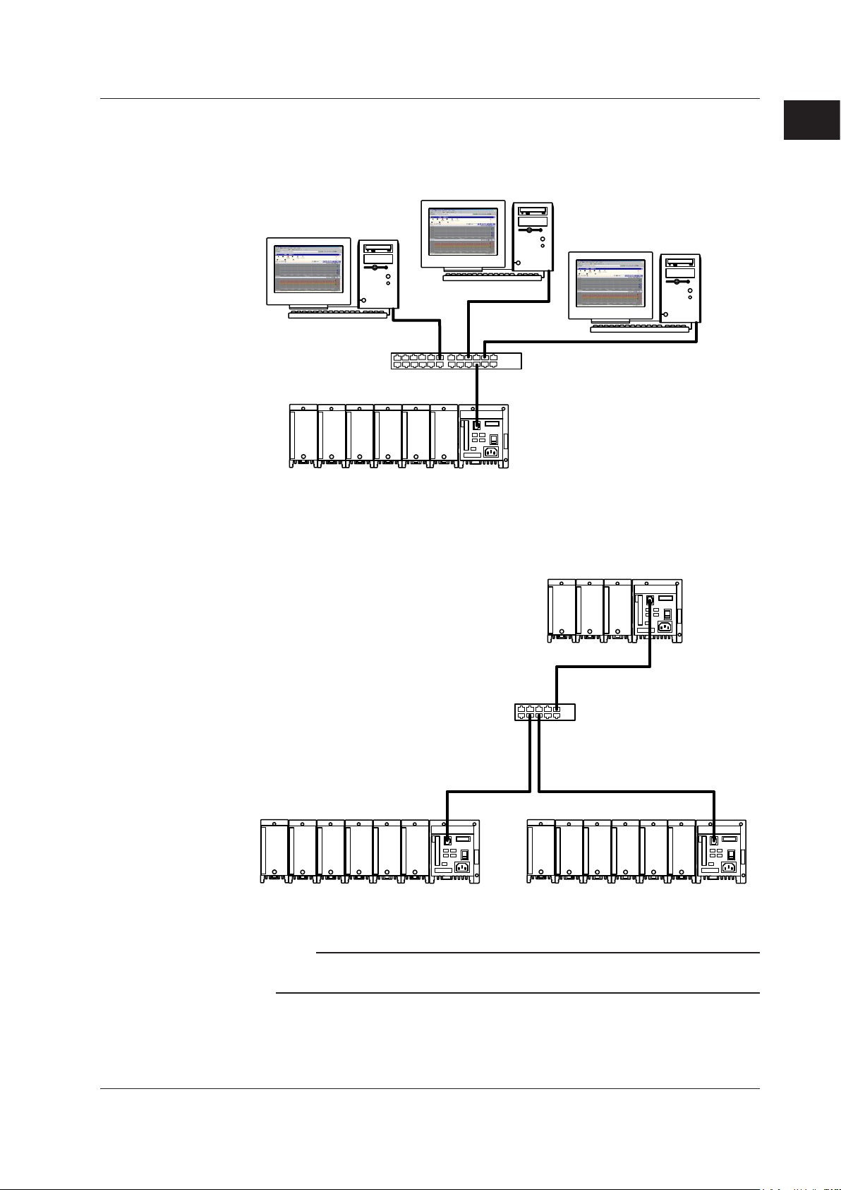
System Configuration
The MW100 Data Acquisition Unit can be flexibly configured for a variety of measuring
environments such as a small-scale system that acquires data on site in a standalone
configuration or a system that allows data acquisition of up to 360 channels using the
Modbus/TCP function.
One-to-one Connection with a PC
This is an example of a system for small scale logging, setting the IP address, and other
tasks.
Explanation of Functions
IM MW100-01E
Standalone Configuration
This is an example of configuration for an on-site standalone data acquisition system.
1-1

MW100
MW100
MW100
Hub
MW100 Data Acquisition Unit
PC
MW100
MW100
MW100
RS-422A/485
PC
MW100 Data Acquisition Unit
1.1 System Overview
One-to-N Connection with a PC
This is an example of a configuration suitable for relatively large scale data acquisition
tasks. Connections can be made via Ethernet or RS-422A/485.
1-2
IM MW100-01E
1
MW100
Hub
MW100 Data Acquisition Unit
PC
PC
PC
Hub
Modbus machine (server)
Modbus machine (server)
MW100 Data Acquisition Unit
(client)
MW100MW100
MW100
1.1 System Overview
One-to-N Connection with the PC
This is an example in which multiple PCs are connected to the MW100 for performing
data monitoring.
Explanation of Functions
Connecting to Modbus Devices
This is an example of configuration of a system with connections to Modbus devices.
Note
Using the Web monitor or other communcation functions while using the Modbus function may
affect the Modbus communication response.
IM MW100-01E
1-3

• Minimum measurement interval: 10 ms
• Maximum number of inputs: 4 inputs
• Input types: DC voltage, TC, 3-wire RTD, and DI (LEVEL,
non-voltage contact)
• Minimum measurement interval: 100 ms
• Maximum number of inputs: 10 inputs
• Input types: DC voltage, TC, 3-wire RTD, and DI (LEVEL,
non-voltage contact)
1.1 System Overview
Main Module
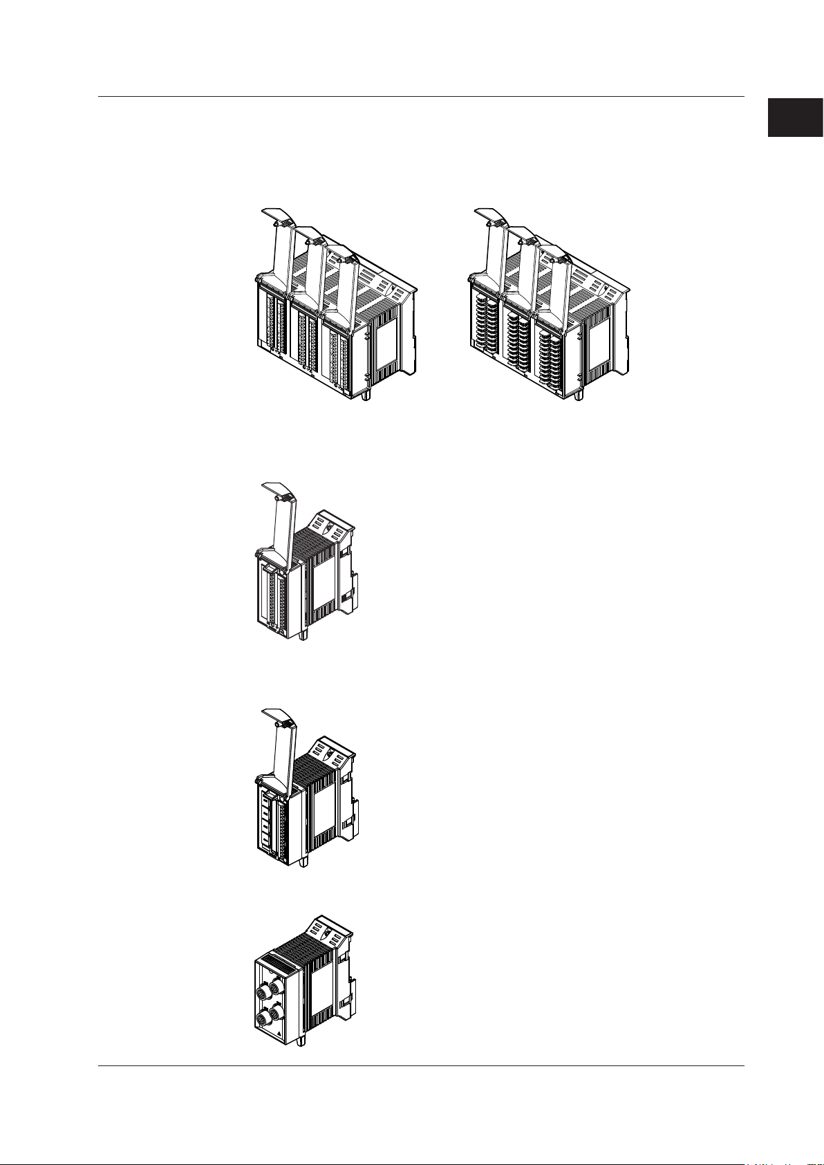
Input/Output Modules
The main module is equipped with power supply connectors, a power switch, Ethernet
ports, and other devices facilitating supply of power to and control of the input/output
modules, and connection to networks.
It also has Start and Stop keys, meaning that since data can be saved to a CF card, data
can be acquired offline. Data acquisition via serial communication is also possible by
adding the RS-232 or RS-422A/485 serial communication option.
The following thirteen types of modules are available. A screw terminal plate and
separately installed screw terminal block (both sold separately) are available as
accessories for the 10-CH, Medium Speed Universal Input Module, the 10-CH, Pulse
Input Module, and the 10-CH, High Speed Digital Input Module.
4-CH, High-Speed Universal Input Module (MX110-UNV-H04)
10-CH, Medium-Speed Universal Input Module (MX110-UNV-M10)
1-4
IM MW100-01E
1
MX110-VTD-L30
(clamp terminals)
MX110-VTD-L30/H3
(M3 screw terminals)
• Minimum measurement interval: 500 ms
• Maximum number of inputs: 30 inputs
• Input types: DC voltage, TC, and DI (LEVEL, non-voltage
contact)
• Minimum measurement interval: 100 ms
• Maximum number of inputs: 6 inputs
• Input types: DC voltage, 4-wire RTD, 4-wire resistance,
and DI (LEVEL, non-voltage contact)
• Minimum measurement interval: 100 ms
• Maximum number of inputs: 4 inputs
• Input system: floating balanced input (isolation between
channels)
• Minimum measurement interval: 100 ms
• Maximum number of inputs: 4 inputs
• Input system: floating balanced input
(non-isolation between channels)
1.1 System Overview
30-CH, Medium Speed DCV/TC/DI Input Module (MX110-VTD-L30, MX110-
VTD-L30/H3)
6-CH, Medium-Speed, Four-Wire RTD Resistance Input Module (MX110-V4R-M06)
Explanation of Functions
4-CH, Medium-Speed Strain Input Module (MX112-B12-M04 and MX112-
B35-M04)
4-CH, Medium-Speed Strain Input Module (MX112-NDI-M04)
IM MW100-01E
1-5

• Minimum measurement interval: 100 ms
• Maximum number of inputs: 10 inputs
• Input types: DI (non-voltage contact, open collector, and 5-V
logic)
• Minimum measurement interval: 10 ms
• Maximum number of inputs: 10 inputs
• Input types: DI (non-voltage contact, open collector, and 5-V
logic)
• Minimum measurement interval: 10 ms
• Maximum number of inputs: 10 inputs
• Input types: DI (24-V logic)
• Output update interval: 100 ms (shortest)
• Maximum number of inputs: 8 outputs
• Output type: DC voltage, DC current
1.1 System Overview
10-CH, Pulse Input Module (MX114-PLS-M10)
10-CH, High-Speed Digital Input Module (MX115-D05-H10)
10-CH, High-Speed Digital Input Module (MX115-D24-H10)
8-CH, Medium-Speed Analog Output Module (MX120-VAO-M08)
1-6
IM MW100-01E

1
• Output update interval: 100 ms (shortest)
• Maximum number of outputs: 8 outputs
• Output type: PWM
• Output update interval: 100 ms (shortest)
• Maximum number of outputs: 10 outputs
• Output type: A contact (SPST)
DIN rail
Base plate
DIN rail mount bracket
1.1 System Overview
8-CH, Medium-Speed PWM Output Module (MX120-PWM-M08)
Explanation of Functions
10-CH, Medium-Speed Digital Output Module (MX125-MKC-M10)
Base Plate
The base plate is equipped with connectors for connecting the main module and input/
output modules. Six different base plates are available to hold from one to six input/
output modules. By attaching the DIN rail mounting brackets that came with the product
to the base plate, you can rack-mount or panel-mount the MW100 main unit.
IM MW100-01E
1-7

1.1 System Overview
PC Software
The MW100 Data Acquisition Unit comes with the MW100 Viewer software program that
allows users to view measured data acquired by the MW100. MW100 Viewer consists
of the three software components described below. For a detailed description of the
functions of these software components, see the MW
(IM MW180-01E).
When configuring a system using the MW100, the software release number and
hardware style number matching conditions must be met (see “Notes” on page i).
100 Viewer
Software User’s Manual
MW100 IP Config Software
Sets the IP address on the MW100. This software is used when setting an IP address for
the first time, or if the current IP address needs to be changed.
MW100 Viewer
Enables you to (1) display measured, computed, and thinning data that has been stored,
(2) read values and perform computation over an area using cursors, and (3) convert the
measured and computed data into various file such as Excel.
MW100 Calibrator Software
This software is used to calibrate the input/output modules connected to the MW100. The
software does not support the pulse input, digital input, or digital output modules.
1-8
IM MW100-01E
1
1.2 MW100 Operation Guide
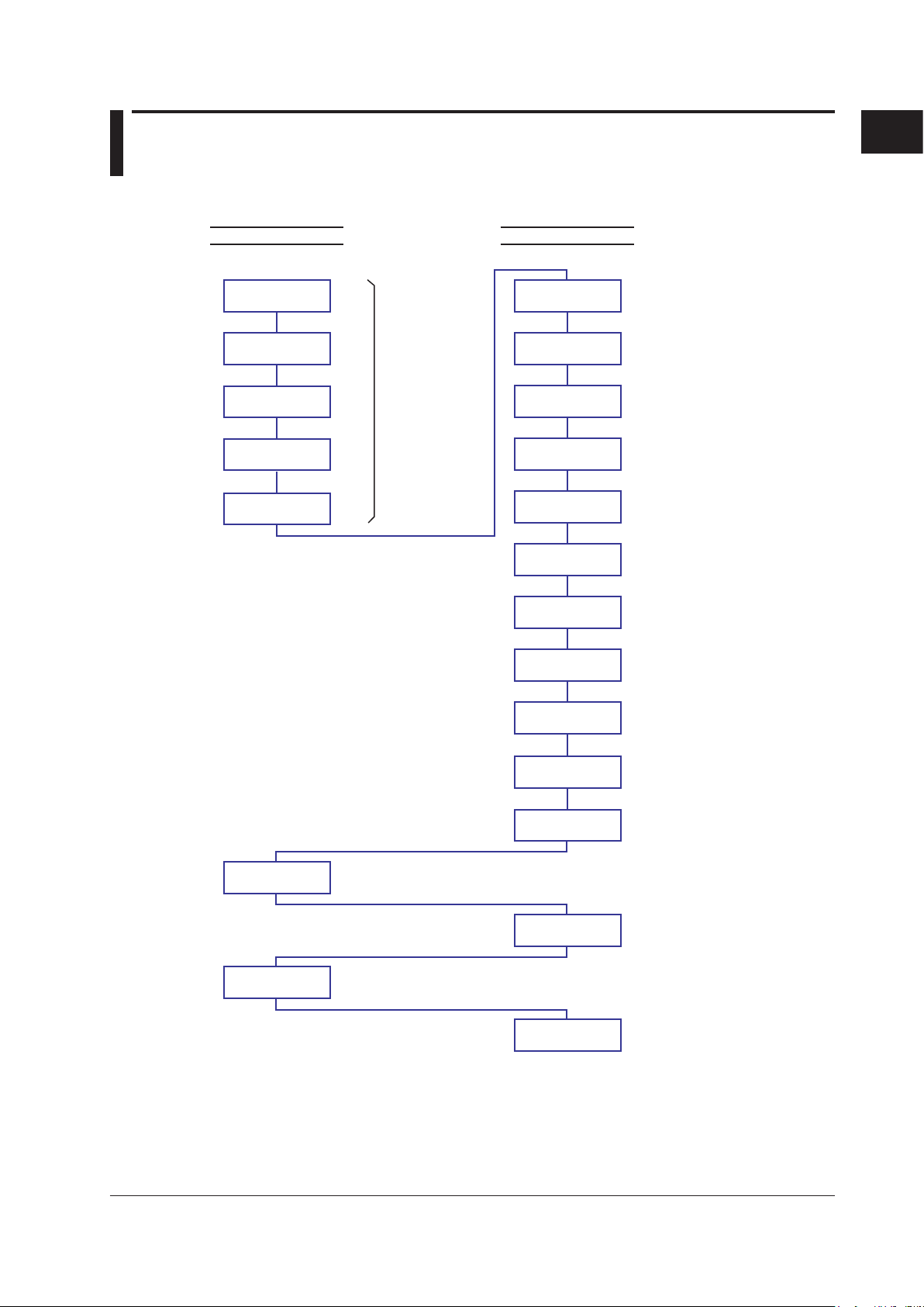
Wire the input/
output modules
Operations on the MW100
Connect
communication
cables
Connect the power
cord
Set up
communication
Configure the
system
Enter data
acquisition
conditions
Set measurement
conditions
MATH settings
FTP and e-mail
settings
Instal the MW100
and attaching the
main module
See the Installation
and Connection
Guide
(IM MX100-72E).
Transmission
output settings
Alarm settings
Event settings
Search for all connected MW100s and
configure network parameters such as
the MW100s’ IP addresses.
Select the acquisition interval to be
used, select the recording interval,
set recording start/stop conditions, etc.
Input channel settings, input type,
measurement range, measurement
span, etc.
Analog/PWM output settings
Event/action settings
Settings for the FTP server, mail server,
and other network utilities
Measured data and alarm display
settings while online
Data display and analysis using MW100
Viewer Software.
See the MW100 Viewer Software User’s
Manual (IM MW180-01E).
While online you can start
measurement, computation, and
recording from a PC
Starting measurement,
computation, and recording
Alarm level and type settings
Alarm output, manual DO, Fail output,
and error output settings
MW100 system configuration, date/time
setting, CF card setup
Section 3.3
Section 3.4
Section 3.5
Section 3.6
Section 3.7
Digital output
settings
MATH channel settings, entry of
expressions, etc.
Section 3.8
Section 3.9
Section 3.14
Display and
check data
Monitor data and
alarms
Section 3.16
Section 3.10 and 3.11
Report settings
Set up creation of hourly, daily, weekly,
or monthly reports
Section 3.12
Section 3.2
Section 2.5
Turn ON the power
switch
Section 2.5
Section 2.6 to 2.8
Section 2.4
Section 2.2 and 2.3
Start measurement,
computation,
or recording
Section 3.13
Section X.X indicates the referred
sections in this manual.
While online you can stop
measurement, computation, and
recording from a PC
Stopping measurement,
computation, and recording
Stop measurement,
computation,
or recording
Section 3.13
Operations on the PC
The figure below shows the general flow of operation when the MW100 is installed
initially.
Explanation of Functions
IM MW100-01E
1-9
1.3 Functions of the Main Module
DATA ACQUISITION UNIT
MEASURE
RECORD
SERIAL RD
ETHERNET
10BASE - T
100BASE - TX
START
100 - 240V AC
STOP
USER 2USER 1
POWER
SW
ON
1 2 876543
MATH
ALARM
TERMN
ON
OFF
SERIAL COMM
FG SDB SDA RDB RDASG
70VA MAX 50 / 60Hz
MEASURE
RECORD
SERIAL RD
MATH
ALARM
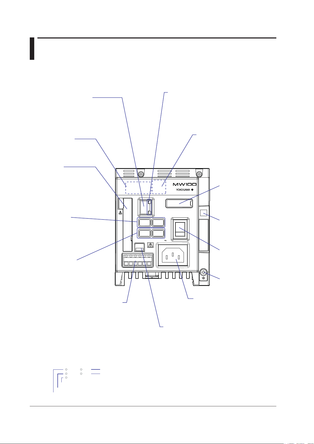
7-segment LED
Displays the operational status of
the MW100 (see “Displays” in this
section, or section 4.1, “7-Segment
LED Error Display”).
Ethernet port
Used for main unit settings
and network connections
(see 2.6, “Connecting an
Ethernet Cable,” or 3.2,
“Connecting to the MW100.”)
Status indicator*
The operational status of the
instrument is indicated by the
illumination of the LED.
Communication status LED
Check the communication status
Top: LINK LED
Illuminates orange when ready for communication
Bottom: ACT LED
Blinks green when packets are sent/received
CF card slot
Insert the CF card to save
data and perform other tasks
(see section 2.10, “Handling of the
CF Card,” or 3.3, “System Settings”).
Terminator switch (/C3 option)
Turns the terminator ON and OFF
(see “Connection Procedure” in section 2.7).
*Status indicators
Illuminate in the following situations. (See section 3.13, “Starting and Stopping Measurement,
Computation, and Recording.”)
Receiving serial communications data
Recording (illuminates), recording stop processing (blinking)
Measuring
Alarm activation or alarm hold
Computing (illuminates), computing stop processing (blinking)
RS-422A/485 connector (/C3 option)
Depending on installed options, the connector may
or may not be available, or it may be an RS-232
connector (/C2 option, see section 2.7,
“Connecting the RS-422A/485 Interface” or 2.8,
“Connecting the RS-232 Interface”),
Power supply inlet
Connect the accessory power supply
cord This is listed as a screw terminal
in the power supply specifications.
Functional ground
terminal
Power switch
Turns the power to the
MW100 main unit ON
and OFF
Dip switch 1
Used to initialize settings,
and for other purposes
(see, “Switches and
Keys” in this section)
Dip switch 2
Not used.
Start/Stop keys
Start and stop measurement,
computation, and recording
(seesection 3.13, “Starting and
Stopping Measurement, Computation,
and Recording”).
User function key
Assign functions to the keys
(see, “Switches and Keys” in this
section)
The main module is the central component of the MW100 Data Acquisition Unit.
Names and Functions of Parts
1-10
IM MW100-01E

1
Switches and Keys
1 2 3 4 5 6 7 8
ON
1 2 3 4 5 6 7 8
ON
1 2 3 4 5 6 7 8
ON
1 2 3 4 5 6 7 8
ON
1 2 3 4 5 6 7 8
ON
1 2 3 4 5 6 7 8
ON
Main unit Web
1 2
ON
1.3 Functions of the Main Module
The MW100 has the following switches and keys. Some are included with options.
• Start and Stop keys
• User function key 1
• User function key 2
• Dip switch 1
• Dip switch 2
• Terminator switch (/C3 option)
• Power switch
User Function Keys
Actions set up using the Event/Action function can be executed by pressing the user
function keys on the front panel of the MW100.
The keys are assigned as follows by default.
Key Display Action
User function key 1 USER1 Write to setting values file
User function key 2 USER2 Load setting values file
Dip Switch 1
Used to initialize the MW100 settings and for other functions.
• Normal operation • Initialization of IP addresses and other settings
Explanation of Functions
• Fixed IP address (192.168.0.10) • 10-Mbps half-duplex Ethernet communication
• Firmware update
Dip Switch 2
Turn all switches ON for normal operation. If the switches are set differently, the
instrument may not function correctly.
Key Lock Function
You can apply a lock to the functions of the Start, Stop, and user function keys. The lock
prevents inadvertent execution of functions.
For setting the key lock, see “Status Information and Processing/Operation” in section 3.3.
IM MW100-01E
1-11
Unit number and dotUnit number
• Keylock release • Keylock
1.3 Functions of the Main Module
Connectors
The MW100 can come with the following connectors. The actually-installed connectors
depend on the power supply input section specifications and options.
• Ethernet
• RS-422A/485 connector (/C3 option)
• RS-232 connector (/C2 option)
•
CF card slot
• Power supply inlet (power supply input section specification: -1M)
• Power supply screw terminals (power supply input section specification: -1W, -2M, -3W)
Displays
The MW100 indicates its operating conditions with the following displays.
• 7-segment LED
• Status indicators
• Communication status LED
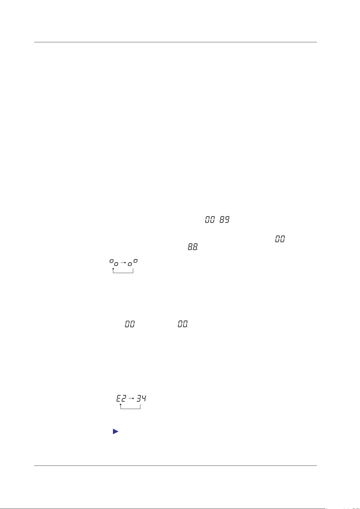
7-Segment LED
Displays the MW100 Data Acquisition Unit’s unit number, operation status, end of
operation, and errors.
• Unit Number Display
Unit numbers can be set from 00 to 89.
- is displayed.
• Display of the Self-Test Operation on Startup
When the power is turned ON the setting of dip switch 1 is displayed
the operation preparation status
self check is in progress, the following displays are repeated.
• Key Lock Status
A key lock function is included for preventing accidental manipulation of the MW100
front panel keys. The key lock status is indicated by a dot at the bottom of the unit
number. The example shown is for a unit of number 00.
• Operation Error Display
In error Exxx (where xxx is a three-digit number), the code is divided into two parts
which are displayed alternately. In the first part, the letter E appears in the left digit
with the hundreds digit of the error code to the right, and the second part consists of
the last two digits of the error code.
Example: Error code E234
, and then a self check is performed. While the
followed by
1-12
Up to three error codes are saved. You can clear one error that is displayed by
pressing the Stop key.
For the contents of error codes and their meanings, see section 4.1, “Errors Displayed on
the 7-Segment LED and Corrective Actions.”
IM MW100-01E

1
In-progress display
Blinking
In-progress display
1.3 Functions of the Main Module
• In-Progress Display
The following displays cycle while the CF card is being accessed or while calibration
is being performed. Do not remove the CF card while it is being accessed.
Explanation of Functions
For the handling of the CF card, see “Handling of the CF Card” in section 2.10.
For CF card replacement, see “Saving Data to the CF Card” in this section.
• Access Forewarning to the CF Card
When saving measured, computed, or thinned data, the dots blink before accessing
of the CF card. This indication starts 10 seconds before the access. If you see this
indication, quickly finish the insertion or removal of the CF card.
If you are using the multi interval function, this indication may be shorter than 10
seconds. If the time until the CF card is accessed is less than or equal to 5 s, the time
until access is displayed numerically.
For CF card replacement, see “Saving Data to the CF Card” in this section.
When performing a manual sample, and when saving report data, the dots do not
blink before accessing of the CF card.
• Non-execution Display
If the file division action is not executed, “--nuLL--” is displayed with the characters
flowing from right to left as shown below. Check the execution condition of the file
division.
Operation Modes and Statuses
The MW100 has a Setting mode in which input ranges and other settings can be entered,
and a Measurement mode in which data acquisition is performed. The mode switches
depending on the measurement item of the status information.
Mode Status Info Description
Measurement
Setting mode Stop For entering range, system, communication, and
Measurement mode Start For data monitoring, computation, and recording
The instrument must be in measurement mode in order for the status of computation and
*
recording to be Start.
display settings
IM MW100-01E
1-13

Time (s)
Measurement interval (MATH interval)
Measured and computed data
Recorded measured and computed data
Recorded measured and computed data
using thinning recording
Recording interval
Recording interval of thinning recording
1.3 Functions of the Main Module
Measurement
Measured data sampled at certain intervals is acquired by the various input modules.
Acquired data is stored in internal memory. During recording, acquired data is saved to
the CF card according to the settings.
In addition, if an alarm occurs or if the main module receives output commands sent from
the PC, the main module generates signal output instructions to the output modules.
Data Sampling
The relationship between the measurement interval and recording interval is as follows:
The measured, computed, or thinned data that is recorded at the recording interval is
saved to the CF card.
For saving data to the CF card, see “Saving Data to the CF Card” in this section.
Multi interval
Filters
1-14
Measurement Intervals
• Synchronization between modules
If set to the same measurement interval, measurements made by input modules in the
same acquisition unit are synchronized.
• Synchronization between channels
On the 4-CH, High-Speed Universal Input Module, the 10-CH, Pulse Input Module,
and the 10-CH, High-Speed Digital Input Module, measurement is synchronized
between channels.
On the 10-CH, Medium-Speed Universal Input Module, 30-CH, Medium Speed
DCV/TC/DI Input Module, Six-Channel Medium-Speed Four-Wire R
TD Resistance
Input Module, and 4-CH, Medium-Speed Strain Input Module, measurement is not
nchronized between channels since measurement occurs sequentially by channel (it
sy
can be said to be synchronized within measurement intervals).
Measurement Groups
Three measurement intervals can be set, and measurement channels can be assigned
to each interval. There is a particular order in which measurement intervals can be set to
measurement groups.
For a description of setting the measurement interval, see section 3.4, “Setting Acquisition
Conditions for Measured/Computed Data.”
A first-order lag filter is available. You can select a time constant (time until 63.2% of
the output value is reached) corresponding to the measurement interval indicated in the
equation below.
T
ime constant = measurement interval × N (where N = 5, 10, 20, 25, 40, 50, or 100)
For details on filters, see section 2.9, “Measures Against Noise on the MW100 Data
Acquisition Unit.”
IM MW100-01E

1
MATH
Scale value =
(X – SP
min
) × (SC
max
– SC
min
)
SP
max
– SP
min
+ SC
min
X: Measured value
SP
max
: Specified span maximum
SP
min
: Specified span minimum
SC
max
: Specified scale maximum
SC
min
: Specified scale minimum
MW100
Thermocouple*
Copper wire
Copper wire
Thermocouple*
Thermocouple*
Relay terminal (to be furnished by the user)
Reference channel
Input terminal
* Use the same type of thermocouples.
MATH (/M1 Option)
1.3 Functions of the Main Module
Differential computation between channels and linear scaling are possible. Linear scaling
converts the measured values for a specific purpose (scaled values) using the following
equation.
MATH Types Notation
Differential computation between channels Delta
Linear scaling Scale
Note that the channels included on the 10-CH Pulse Input Module are only available for
integration (TLOG.PSUM).
Expressions using measured and computed data as variables can be entered and
executed on channels dedicated for computation, and the results can be displayed and
saved. Computations are executed every measurement interval (shortest interval is 100
ms).
For details, see section 1.15, “MATH Functions (/M1 Option).”
Explanation of Functions
Report Function (/M3 Option)
You can perform statistical computations on measurement or MATH channel data
and display and save the results. The types of reports are hourly, daily, weekly, or
monthly. Reports can be created using the maximum, minimum, average, integral, and
instantaneous values from up to 60 channels.
For details on the report function, see section 1.16, “Report Function (/M3 Option).”
Remote RJC (RRJC)
When the item to be measured is located at a great distance, you can set up relay
terminals near the item, measure the temperature difference between the relay terminal
and the input terminal of the input module (reference channel) using thermocouples,
and use the resultant electromotive force as the reference junction compensation of
the temperature measurement. By connecting a copper wire between the relay terminal
and input terminal of the input module, and a thermocouple between the DUT and relay
terminal, you can measure the temperature of the DUT without the need for a large
amount of expensive thermocouples.
Burnout
IM MW100-01E
When the input mode is set to thermocouple (TC), you can set the burnout detection
behavior. Measured values become “range over” during detection.
Detection Behavior Notation
No detection Off
Measured values fixed at +range over Up
Measured values fixed at –range over Down
1-15

1.3 Functions of the Main Module
Range Over
When the MW100 detects a range over (see below) on a measurement or MATH
channel, “+Over” or “–Over” is displayed.
• Measurement channel range over
• During DC voltage input, strain input, and resistance (20 Ω, 200 Ω, etc.), a range
•
During high-resolution DC voltage input and pulse input, a value less than 0% of
• If the input type is thermocouple or RTD, excluding the cases where the
•
On channels that use linear scaling, the range-over values, after removing the
•
When you are performing differential computation between channels, if the
•
MATH channel range over
See “Math Span” on page 1-67 in section 1.15, “MATH Function (/M1 Option).”
over is detected if the value that is measured on a measurement channel is outside
of the measurable range by more than ±5%. For example, when the measurement
range is 2 V
2.2000 V or goes below –2.2000 V, a range over is detected.
the measurable range is a negative range over, and a value greater than 105% of
the measurable range is a positive range over
thermocouple or R
temperature goes more than approximately 10°C above or below the measurable
range. For example, when the measurement range is set to R, the measurable
range is 0.0 to 1760.0°C. If the temperature exceeds 1770.0°C, “+Over” will be
displayed. If the temperature goes below –10.0°C, “–Over” will be displayed. The
special ranges mentioned here are ranges such as KpvsAu7Fe or J263. If you
are using a special range, “–Over” will be displayed if the temperature goes below
approximately 0°C.
decimal point, are above 32000 and below –32000. However, even if the measured
value is within ±30000, if it is a range-over value according to the previous range, it
will be handled as a range-over value.
measured value is outside of the measurable range, a range over will be detected.
When you are using a sensor such as a thermocouple, the measurable range
when performing dif
measurable range when not performing differential computation between channels.
, the measurable range is –2.0000 to 2.0000 V. If the voltage exceeds
.
TD has a special range, a range over is detected when the
ferential computation between channels may be larger than the
1-16
IM MW100-01E
 Loading...