

Page 1

User’s
Manual
Models MV1004/MV1006/MV1008/MV1012/MV1024
MV2008/MV2010/MV2020/MV2030/MV2040/MV2048
MV1000/MV2000
Communication Interface
IM MV1000-17E
2nd Edition
Page 2

i
IM MV1000-17E
Thank you for purchasing the MV1000/MV2000 (hereafter referred to as the MV).
This Communication Interface User’s Manual contains information about the Ethernet
and serial interface communication functions. To ensure correct use, please read this
manual thoroughly before beginning operation.
Keep this manual in a safe place for quick reference in the event a question arises.
The following manuals, including this one, are provided as MV1000/MV2000 manuals.
Please read all of them.
• Electronic Manuals Provided on the Accompanying CD-ROM
Manual Title Manual No. Description
MV1000
First Step Guide
IM MV1000-02E Explains how to set up the MV1000 for
making measurements using the quick
settings function. Connection diagrams are
also provided to help you with the setup.
MV2000
First Step Guide
IM MV2000-02E Explains how to set up the MV2000 for
making measurements using the quick
settings function. Connection diagrams are
also provided to help you with the setup.
MV1000/MV2000
User’s Manual
IM MV1000-01E Explains all functions except communication
functions and procedures of the MV1000 and
MV2000.
MV1000/MV2000
Communication Interface
User’s Manual
IM MV1000-17E Explains the MV1000 and MV2000 Ethernet
and serial interface communication functions.
• Paper Manuals
Manual Title Manual No. Description
MV1000
First Step Guide
IM MV1000-02E This guide is also provided in the CD-ROM.
MV2000
First Step Guide
IM MV2000-02E This guide is also provided in the CD-ROM.
MV1000/MV2000
Control of Pollution
Caused by the Product
IM MV1000-91C
Provides information about pollution control.
• DAQSTANDARD Manuals
All manuals other than IM 04L41B01-66EN are contained in the DAQSTANDARD CD.
Manual Title Manual No.
DAQSTANDARD Viewer User's Manual IM 04L41B01-63EN
DAQSTANDARD Hardware Setup User's Manual IM 04L41B01-64EN
DAQSTANDARD DX100P/DX200P Hardware Configurator User's
Manual
IM 04L41B01-65EN
Installing DAQSTANDARD IM 04L41B01-66EN
Notes
• The contents of this manual are subject to change without prior notice as a result of
continuing improvements to the instrument’s performance and functions. The gures
given in this manual may differ from those that actually appear on your screen.
•
Every effort has been made in the preparation of this manual to ensure the accuracy
of its contents. However, should you have any questions or nd any errors, please
contact your nearest
YOKOGAWA dealer.
• Copying or reproducing all or any part of the contents of this manual without
YOKOGAWA’s permission is strictly prohibited.
•
The TCP/IP software of this product and the document concerning the TCP/IP software
have been developed/created by YOKOGAWA based on the BSD Networking Software
,
Release 1 that has been licensed from the Regents of the University of California.
2nd Edition : August 2010 (YK)
All Rights Reserved, Copyright © 2007 Yokogawa Electric Corporation
Page 3

ii
IM MV1000-17E
Trademarks
• MVAdvanced is a trademark of Yokogawa Electric Corporation.
• Microsoft and Windows are either registered trademarks or trademarks of Microsoft
Corporation in the United States and/or other countries.
• Adobe and Acrobat are trademarks of Adobe Systems Incorporated.
•
Company and product names that appear in this manual are registered trademarks or
trademarks of their respective holders.
• In this manual, the ™ and ® symbols do not accompany trademarks or registered
trademarks.
Revisions
• 1st Edition: December 2007
• 2nd Edition: August 2010
Page 4

iii
IM MV1000-17E
How to Use This Manual
The following symbols are used in this manual.
Unit
• k stands for 1000. Example: 5 kg, 100 kHz
• K stands for 1024. Example: 640 KB
Markings
The following safety notations are used in this manual.
Improper handling or use can lead to injury to the user or damage
to the instrument. This symbol appears on the instrument to
indicate that the user must refer to the user's manual for special
instructions. The same symbol appears in the corresponding place
in the user’s manual to identify those instructions. In the manual,
the symbol is used in conjunction with the word WARNING or
CAUTION.
WARNING
Calls attention to actions or conditions that could cause serious or
fatal injury to the user, and precautions that can be taken to prevent
such occurrences.
CAUTION
Calls attentions to actions or conditions that could cause light
injury to the user or damage to the instrument or user’s data, and
precautions that can be taken to prevent such occurrences.
Note
Calls attention to information that is important for proper operation
of the instrument.
Bold Characters
Bold characters are used to indicate text that appears on the screen or operation keys.
The ◊ symbol indicates key and menu operations.
Procedural Explanations
This manual mainly describes the MV1000 procedures. Where procedures differ between
the MV2000 and MV1000, the MV2000 procedures are also provided.
High-Speed and Medium-Speed Model Groupings
This manual uses the terms high-speed input model and medium-speed input model to
distinguish between MV models as follows:
Model Type Model
High-speed input model MV1004, MV1008, and MV2008
Medium-speed input model MV1006, MV1012, MV1024,
MV2010, MV2020, MV2030, MV2040, and MV2048
Page 5

iv
IM MV1000-17E
Communication Ports
Rear Panel
MV1000
RS-232 port (option)
A serial port provided with the
/C2 option.
RS-422/RS-485 port (option)
A serial port that is provided with the /C3 option.
Ethernet port
MV2000
RS-232 port (option)
A serial port provided with the
/C2 option.
RS-422/RS-485 port (option)
A serial port that is provided with the /C3 option.
Ethernet port
An Ethernet port that comes standard.
Page 6

v
IM MV1000-17E
1
2
3
4
5
6
7
App
Index
Contents
How to Use This Manual .................................................................................................................. iii
Communication Ports.......................................................................................................................iv
Chapter 1 Overview of Communication Functions
1.1 Ethernet Interface ................................................................................................................ 1-1
1.2 Serial Interface ..................................................................................................................... 1-7
1.3 Modbus Protocol .................................................................................................................. 1-8
Chapter 2 Using the Ethernet Interface
2.1 Workflow for Using the Ethernet Interface ........................................................................... 2-1
2.2 Connecting the MV .............................................................................................................. 2-2
2.3 Sending E-mail Messages ................................................................................................... 2-8
2.4 Monitoring the MV on a PC Browser ................................................................................. 2-17
2.5 A
cce
ssing Measured Data Files on the MV from a PC .....
..................................................... 2-23
2.6 Transferring Data Files from the MV .................................................................................. 2-25
2.7 Synchronizing the Time .....................................................................................................
2-28
2.8 Reading/Writing the MV Data from Another Device via Modbus
....................................... 2-30
2.9 Reading/Writing Data on Another Device from the MV via Modbus
.................................. 2-31
2.10 Usage Example of the Modbus Function ........................................................................... 2-40
Chapter 3 Using the Serial Interface
3.1 Workflow for Using the Serial Interface................................................................................ 3-1
3.2 Connecting the MV .............................................................................................................. 3-2
3.3 Configuring the Serial Interface ........................................................................................... 3-8
3.4 Reading/W
riting the MV Data from Another Device via Modbus
......................................... 3-9
3.5 Reading/Writing Data on Another Device from the MV via Modbus
.................................. 3-10
3.6 Usage Example of the Modbus Function ........................................................................... 3-13
Chapter 4 Commands
4.1 Command Syntax ................................................................................................................ 4-1
4.2 A List of Commands ............................................................................................................. 4-3
4.3 Setup Parameters ................................................................................................................ 4-8
4.4 Setting Commands (Setting) ..............................................................................................
4-10
4.5 Setting Commands (Control) ............................................................................................. 4-24
4.6 Basic Setting Commands .................................................................................................. 4-28
4.7 Output Commands (Control) .............................................................................................. 4-39
4.8 Output Commands (Setting/Measured/Computed Data Output) .......................................
4-40
4.9 Output Commands (RS-422/485 Commands) ................................................................... 4-42
4.10 Output Commands (Special Response Commands) .........................................................
4-43
4.11
Maintenance/Test Commands (available when using the maintenance/test server function
via the Ethernet interface) ..................................................................................................
4-43
4.12 Instrument Information Output Commands (available when using the instrument information
server function via the Ethernet interface) ......................................................................... 4-45
Page 7

vi
IM MV1000-17E
Chapter 5 Responses
5.1 Response Syntax ................................................................................................................. 5-1
5.2 Text Data Output Format ..................................................................................................... 5-6
5.3 Binary Data Output Format ................................................................................................ 5-27
5.4 Instrument Information Output Format
............................................................................... 5-32
Chapter 6 Status Reports
6.1 Status Information and Filter ................................................................................................ 6-1
6.2 Status Information Bit Structure ........................................................................................... 6-2
Chapter 7 Specifications
7.1 Ethernet Interface Specifications ......................................................................................... 7-1
7.2 Serial Interface Specifications ............................................................................................. 7-2
7.3 Modbus Protocol Specifications ........................................................................................... 7-3
Appendix
Index
Contents
Page 8

IM MV1000-17E
1-1
Overview of Communication Functions
1
1.1 Ethernet Interface
This chapter gives an overview of the MV Ethernet communication functions.
Modbus Communications
The MV can connect to a Modbus device and read and write to the device’s internal
registers. See section 1.3 for details.
Setting/Measurement Server
• You can use this feature to set almost all of the settings that can be configured from
the front panel keys. However, you cannot use this feature to turn the power ON/OFF,
register users, set the key lock password, or set the connection destination of the FTP
client function.
•
You can use this feature to transmit the following types of data.
• Measured, computed
1
, and external input data
2
• Files in the internal memory or files on an external storage medium
• Setup information and status byte
• Logs of operations errors, communications, etc.
• Alarm summaries and message summaries
• Relay status information
Measured, computed
1
, and external input2 data can be transmitted to a PC in binary
or ASCII format. Other types of data are transmitted in text format. For a description of
data output formats, see chapter 5.
1 /M1 option.
2 MV2000 with the /MC1 option.
• You can use setting mode commands (see sections 4.4 and 4.5), basic setting mode
commands (see section 4.6), and output commands (see sections 4.7 and 4.8) with
this feature.
•
You can use this feature via an Ethernet interface or serial interface (/C2 or /C3
option).
• If you want to use this feature via a serial interface, configure t
he serial interface
according to Chapter 3.
Maintenance/Test Server
• You can use this feature to transmit connection information, network statistics, and
other Ethernet communication information from the MV.
• You can use maintenance/test commands (see section 4.11) with this feature.
Chapter 1 Overview of Communication Functions
Page 9
IM MV1000-17E
1-2
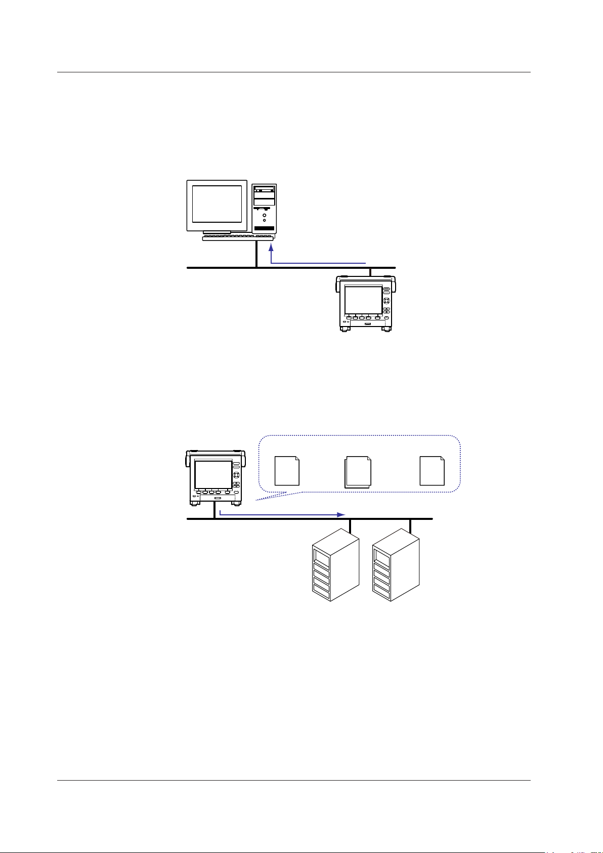
FTP Server
• You can access the MV from a PC via FTP. You can perform operations such as
retrieving directory and file lists and transferring and deleting files from an external
storage medium connected to the MV. You can also retrieve directory and file lists and
transfer files from the internal memory.
•
For the settings necessary to use this feature, see section 2.5.
Files on an external storage medium
PC
FTP server
Ethernet
MV
FTP Client
Automatic File Transfer
• You can use this feature to automatically transfer display, event, report, and snapshot
data files that are created in the MV internal memory to an FTP. The result of the
transfer is recorded in the FTP log. You can view the FTP log on the MV (see “Log
Display” described later) or transmit the log to a PC using commands.
Data files
FTP server
Primary
Secondary
Ethernet
Transfer destination
(FTP server) information
Transfer log
(FTP log)
Data files to
be transferred
FTP client
MV
You can specify two destination FTP servers: primary and secondary. If the primary
FTP server is down, the file is transferred to the secondary FTP server.
• For the settings necessary to use this feature, see section 2.6.
• FTP Test
• You can perform an FTP test by transferring a test file from the MV to an FTP
server.
• You can view the result of the FTP test on the FTP log screen.
•
For information on how to use this feature, see section 2.6.
1.1 Ethernet Interface
Page 10

IM MV1000-17E
1-3
Overview of Communication Functions
1
Instrument Information Server
• You can use this feature to output the serial number, model name, and other
information about an MV that is connected via an Ethernet network.
• You can use instrument information output commands (see section 4.12) with this
feature.
Login
• You can use this feature when accessing the setting/measurement server,
maintenance/test server, and FTP server functions via an Ethernet interface.
• For a description of the settings required to use this feature, see the MV1000/MV2000
User’
s Manual (IM MV1000-01E).
•
For the procedure to log into the setting/measurement server or the maintenance/test
server, see appendix 3.
User Registration
Users are registered using the MV login feature. There are two user levels: administrator
and user.
• Administrator
An administrator has privileges to use all the features of the setting/measurement
server, maintenance/test server, and FTP server.
• User
A user has limited privileges to use the features of the setting/measurement server,
maintenance/test server, and FTP server. For command limitations, see section 4.2.
• Setting/measurement server feature limitations
A user cannot change settings that affect the MV operation. A
user can output
measured data and setting data.
• Maintenance/test server feature limitations
A user cannot disconnect a connection between another PC and the MV.
A user
can disconnect the connection between the user’s own PC and the MV.
• FTP server feature limitations
A user cannot save or delete files on an external storage medium connected to the
MV
. A user can only load files.
• Application Timeout
This feature drops the connection with the PC if there is no data transfer for a given
time. It prevents a PC from being connected to the MV indefinitely which would
prohibit other users from making new connections.
1.1 Ethernet Interface
Page 11

IM MV1000-17E
1-4
Web Server
• The MV screen can be displayed in Microsoft Internet Explorer.
• The following two pages are available.
• Monitor page: A dedicated monitoring screen.
• Operator page: You can switch the MV display and change or write messages.
You can set access control (user name and password specified with the login
function) for each page.
• The MV screen can be refreshed at a constant interval (approximately 10 s).
• The following information can be displayed.
• Alarm summary
• Measured and computed values of all channels
• Log (message log, error log, etc.)
• For Web server feature settings, see section 2.4.
• For a description of the monitor page and operator page operations, see section 2.4.
1.1 Ethernet Interface
Page 12

IM MV1000-17E
1-5
Overview of Communication Functions
1
E-mail Transmission
E-mail Transmission
The available e-mail types are listed below. The MV can automatically transmit
each e-mail type. You can specify two destination groups and specify one of the two
destination groups for each e-mail type. You can also set a header string for each type.
•
Alarm e-mail
Reports alarm information when an alarm occurs or clears.
• System e-mail
When the MV recovers from a power failure, it reports the time of the power failure
and the time of recovery.
Reports the detection of a memory shortage when it is detecte
d.
Reports the error code and message when a media error occurs (when an error
occurs on an external storage medium or when data cannot be stored due to
insufficient free space on an external storage medium).
Reports the error code and message when an FTP
client error (when data transfer
fails using the FTP client feature) occurs.
• Scheduled e-mail
T
ransmits a message when the specified time is reached. You can use this feature to
check that the network and e-mail transmission functions are working properly
. You
can specify a reference time and e-mail transmission interval for each destination.
•
Report e-mail (only on models with the computation function, /M1 option)
Transmits report results.
You can specify POP
before SMTP if authentication is necessary before transmission.
For e-mail transmission settings, see section 2.3.
For e-mail transmission formats, see section 2.3.
For the procedure to start/stop e-mail transmission, see section 2.3.
From: MV1000@daqstation.com
Date: Tue, 22 Jan 2008 08:00:45 +0900 (JST)
Subject: Periodic_data
To: user1@daqstation.com, user2@mvadv.co.jp
LOOP1
TEMPERATURE
Time
Host name
MV1000
Time of transmission
01/05 08:00:01
Header 1
Subject
Example of an e-mail sent at a scheduled time
Header 2
E-mail Transmission Test
• You can test e-mail transmission by sending a test mail from the MV to a destination.
• You can view the test result in the e-mail log screen.
• For information on how to use this feature, see section 2.3.
1.1 Ethernet Interface
Page 13

IM MV1000-17E
1-6
SNTP Server/Client
The client feature retrieves time information from a specified SNTP server at a specified
interval.
The server feature can provide time information to MVs and other devices connected to
the same network.
DHCP Client
You can use this feature to automatically obtain an IP address from a DHCP server. You
can manually retrieve or release network information.
Other Features
Ethernet Interface Connection Status Check
You can check the Ethernet interface connection status on the MV rear panel or the MV
screen.
For a description of the connection status indicators, see section 2.2.
Keepalive (TCP extension feature)
This feature drops the connection if there is no response to a test packet that is
periodically transmitted at the TCP level.
For the settings necessary to use this feature, see section 2.2.
Log Display
You can display operation logs on the MV log screen. You can also check logs
using communication commands. The Web screen can also display logs (except
communication and DHCP logs).
•
Error log screen: A log of operation errors
•
Communication log screen: A setting/measurement server communication input/
output log
• FTP log screen:
A log of file transfers carried out using the FTP client
feature
• WEB log screen: A W
eb server operation log
• Mail log screen: A log of e-mail transmissions
• Login log screen: A login/logout log
• SNTP log screen: An SNTP server access log
• DHCP log screen: A DHCP server access log
• Modbus log screen: A Modbus status (master/client operating condition) log
For the procedure to show the log screen and details on the displayed contents, see the
MV1000/MV2000 User’s Manual (IM MV1000-01E).
For details on the Modbus status log, see section 2.8.
For details on how to output logs using communication commands, see section 5.2. For
details on how to show logs on the Web screen, see section 2.4.
1.1 Ethernet Interface
Page 14

IM MV1000-17E
1-7
Overview of Communication Functions
1
1.2 Serial Interface
The MV supports serial communications via the RS-232 and RS-422/RS-485. This
chapter gives an overview of the MV serial communication functions.
Modbus Communications
• The MV can connect to a Modbus device and read and write to the device’s internal
registers. See section 1.3 for details.
Setting/Measurement Server
• You can use this feature to set almost all of the settings that can be configured from
the MV front panel keys. See section 1.1 for details.
• For the settings necessary to use this feature, see section 3.3.
Page 15
IM MV1000-17E
1-8
1.3 Modbus Protocol
Modbus Client/Master
• The MV can connect to a Modbus server or slave device and read and write to the
device’s internal registers.
The MV can handle the data that is read from the registers as communication input
data on a computation channel (computation function
1
). The MV can also handle the
data on an external input channel.
2
The MV can write measured and computed data to the registers.
1 /M1 option.
2 MV2000 with the /MC1 option.
• For details on the Modbus function codes that the MV supports, see section 7.3.
• For the settings to use the Modbus client feature, see section 2.9. For the settings to
use the Modbus master feature, see sections 3.3, 3.5, and 3.6.
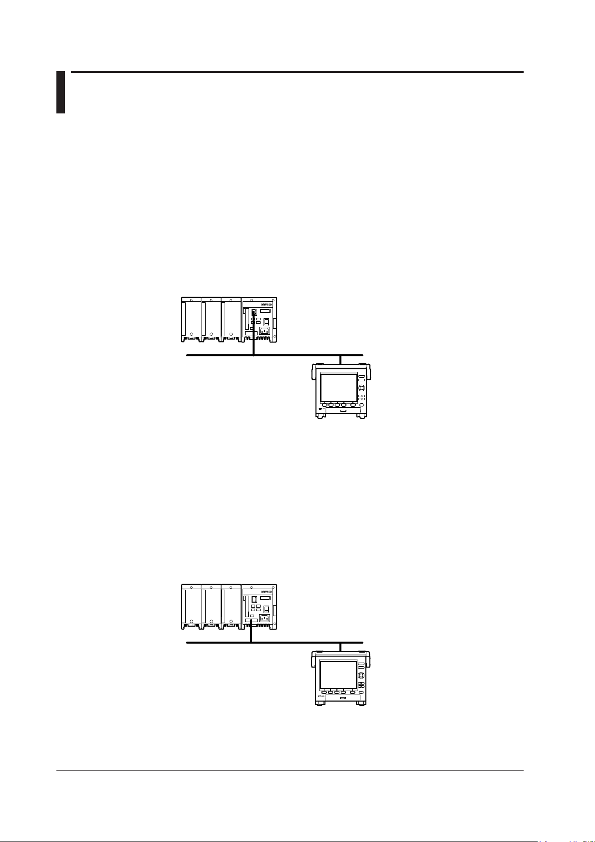
Server Device Connection Example
Modbus server device
MV (client)
Ethernet
MV
Modbus Server/Slave
• A Modbus client (master) device can connect to an MV, a Modbus server (slave)
device, to read the measured, computed,
1
or external input2 data that is written in the
input register or to read or write data to communication input data
1
or to an external
input channel
2
through the MV hold register.
1 /M1 option.
2 MV2000 with the /MC1 option.
• For details on the Modbus function codes that the MV supports, see section 7.3.
• For the settings to use the Modbus client feature, see section 2.8. For the settings to
use the Modbus master feature, see sections 3.3, 3.4, and 3.6.
Example of a Connection with a Modbus Master Device
Modbus master device
MV (slave)
Serial communication
MV
Page 16

IM MV1000-17E
2-1
Using the Ethernet Interface
1
2
2.1 Workflow for Using the Ethernet Interface
Follow the flowchart below to configure Ethernet communication.
Set the host name
Fixed IP address
Automatically assigned IP address (DHCP)
Set the domain
name
Set the Obtain DNS
info item
Set the Host name
registration
Connect the ports
Start
Set the IP address
Set the host name
(optional)
IP address
assignment method
Set the domain
name (optional)
Set the subnet
mask
Set the default
gateway
Set the DNS server
search order
Set the domain suffix
search order
Set the DNS server
search order
Not set when Obtain
DNS info is set to Use.
Not set when Obtain
DNS info is set to Use.
End
Chapter 2 Using the Ethernet Interface
Page 17
IM MV1000-17E
2-2
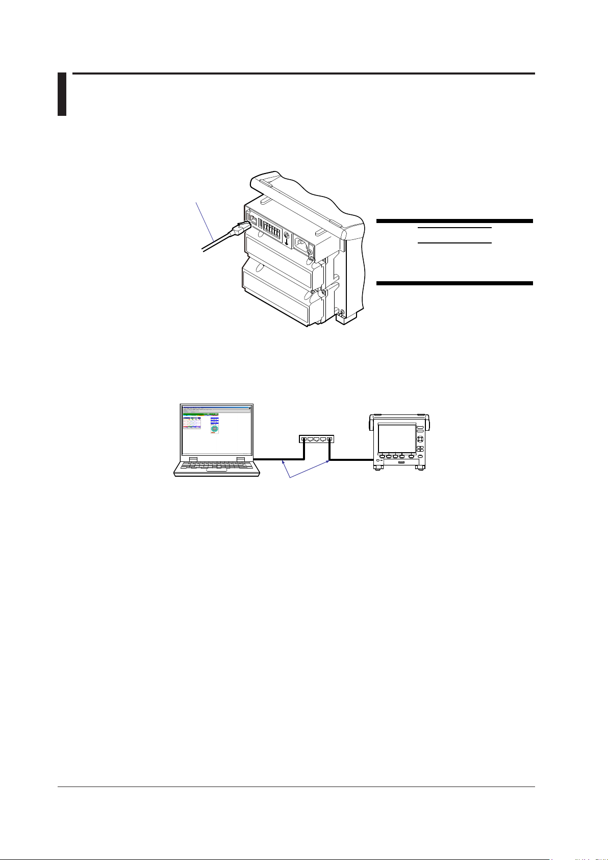
2.2 Connecting the MV
Connecting to the Port
Ethernet Port
Connect an Ethernet cable to the Ethernet port on the MV rear panel.
Ethernet cable
CAUTION
Be sure to connect an Ethernet cable
with an FCC-compliant plug. Otherwise,
the MV may malfunction.
Connecting to a PC
Connect the MV to a PC via a hub. To make a one-to-one connection, see the figure
below. You can connect multiple MVs to a single PC in the same way.
Hub
MV
Ethernet cable
PC
Page 18
IM MV1000-17E
2-3
Using the Ethernet Interface
1
2
Setting the IP Address, Host Information, and DNS
MV1000
◊ Press MENU and then select Menu tab > Basic setting mode > Menu tab >
Communication (Ethernet) > IP address
◊
Press MENU and then select MENU tab >
Basic setting mode > Menu tab >
Communication (Ethernet) > Host settings
◊
Press MENU and then select MENU tab >
Basic setting mode > Menu tab >
Communication (Ethernet) > DNS settings
MV2000
◊
Press MENU and then select MENU tab >
Basic setting mode > Menu tab >
Communication (Ethernet) > IP address, Host settings
◊
Press MENU and then select Menu tab >
Basic setting mode > Menu tab >
Communication (Ethernet) > DNS settings
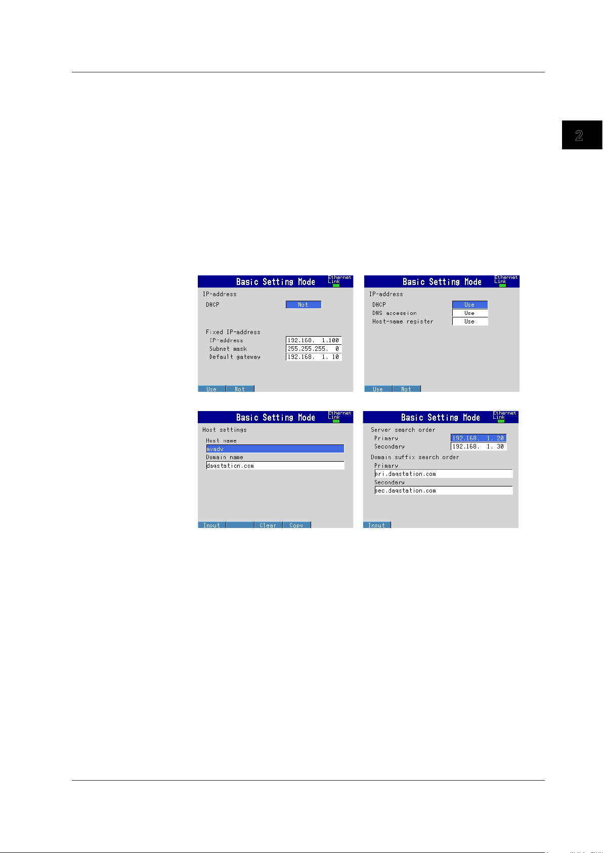
IP address settings (DHCP set to Not)
IP address settings (DHCP set to Use)
Host name settings DNS settings
Set the IP address to a fixed IP address or obtain it automatically (DHCP).
Consult with your network administrator for network parameters such as the IP address,
subnet mask, default gateway, and DNS.
2.2 Connecting the MV
Page 19

IM MV1000-17E
2-4
When Using a Fixed IP Address
• DHCP
Set DHCP to Not.
• IP address
Set the IP address to be assigned to the MV.
• Subnet mask
Set the subnet mask according to the system or network that the MV belongs to.
• Default gateway
Set the gateway IP address.
• Host name
Set the MV host name using up to 64 alphanumeric characters. You do not have to set
this parameter.
• Domain name
Set the name of the domain that the MV belongs to using up to 64 alphanumeric
characters. You do not have to set this parameter.
• Server search order
Register up to two IP addresses for the primary and secondary DNS servers.
• Domain suffix search order
Set up to two domain suffixes: primary and secondary.
When Obtaining an IP Address Automatically (DHCP)
• DHCP
Set DHCP to Use.
• Obtain DNS info
To automatically obtain the DNS server address, select Use. Otherwise, select Not. If
you select Not, you must set the server search order.
• Host name registration
To automatically register the host name to the DNS server, select Use.
• Host name
Set the MV host name using up to 64 alphanumeric characters.
• Domain name
Set the name of the domain that the MV belongs to using up to 64 alphanumeric
characters. This parameter is valid when Obtain DNS info is set to Not.
• Server search order
Register up to two IP addresses for the primary and secondary DNS servers.
• Domain suffix search order
Set up to two domain suffixes: primary and secondary.
2.2 Connecting the MV
Page 20
IM MV1000-17E
2-5
Using the Ethernet Interface
1
2
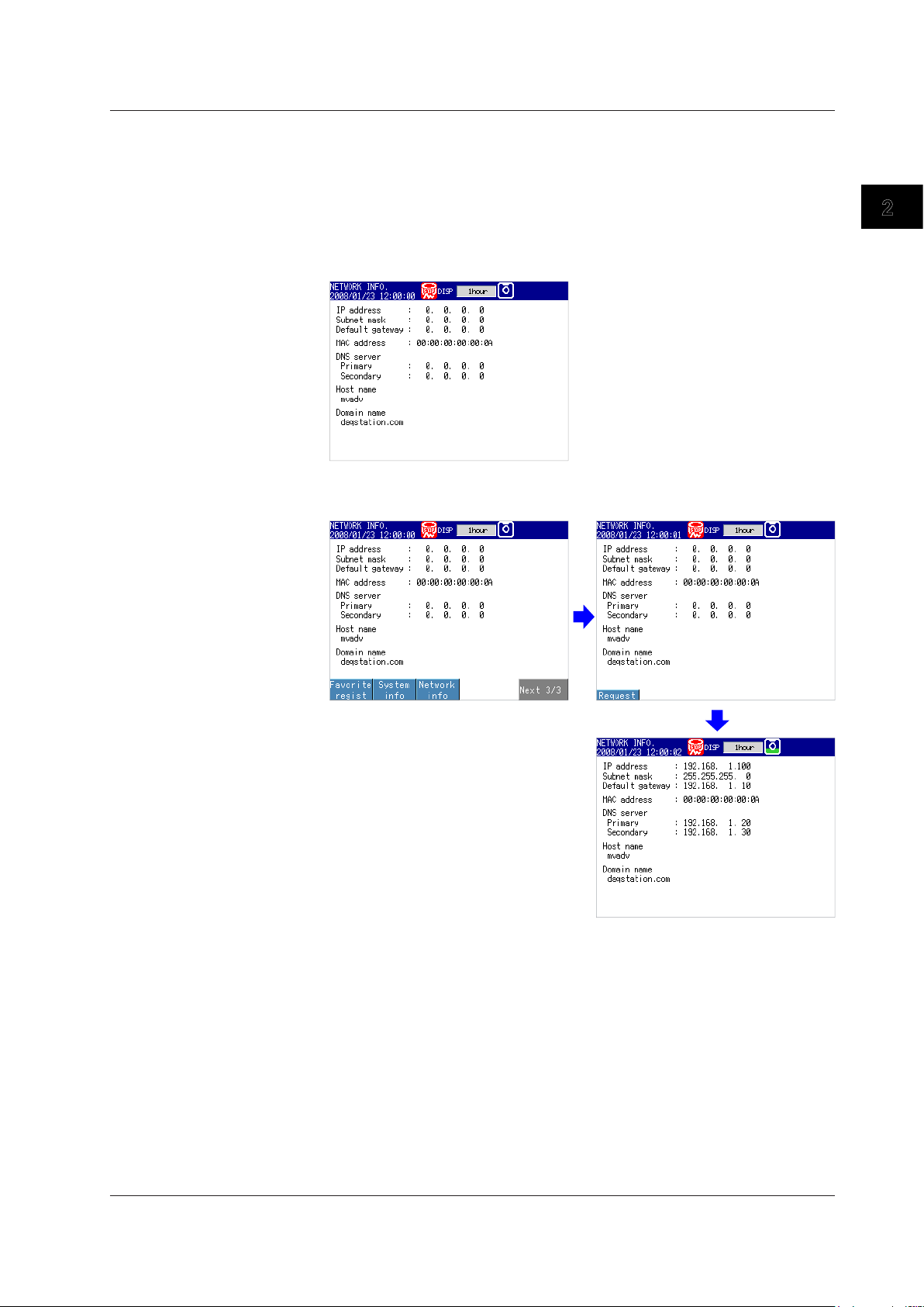
Requesting/Clearing Network Information through DHCP
You can manually request or release IP address and other network information. This
operation applies when DHCP is set to Use. First switch to the network information
screen and then execute the request or release (clear) operation.
Requesting Network Information
1.
Switch to the network information screen.
◊ Press FUNC > Network info
2.
Request network information.
◊ Press FUNC > Network info > Request
The retrieved network information appears.
2.2 Connecting the MV
Page 21
IM MV1000-17E
2-6
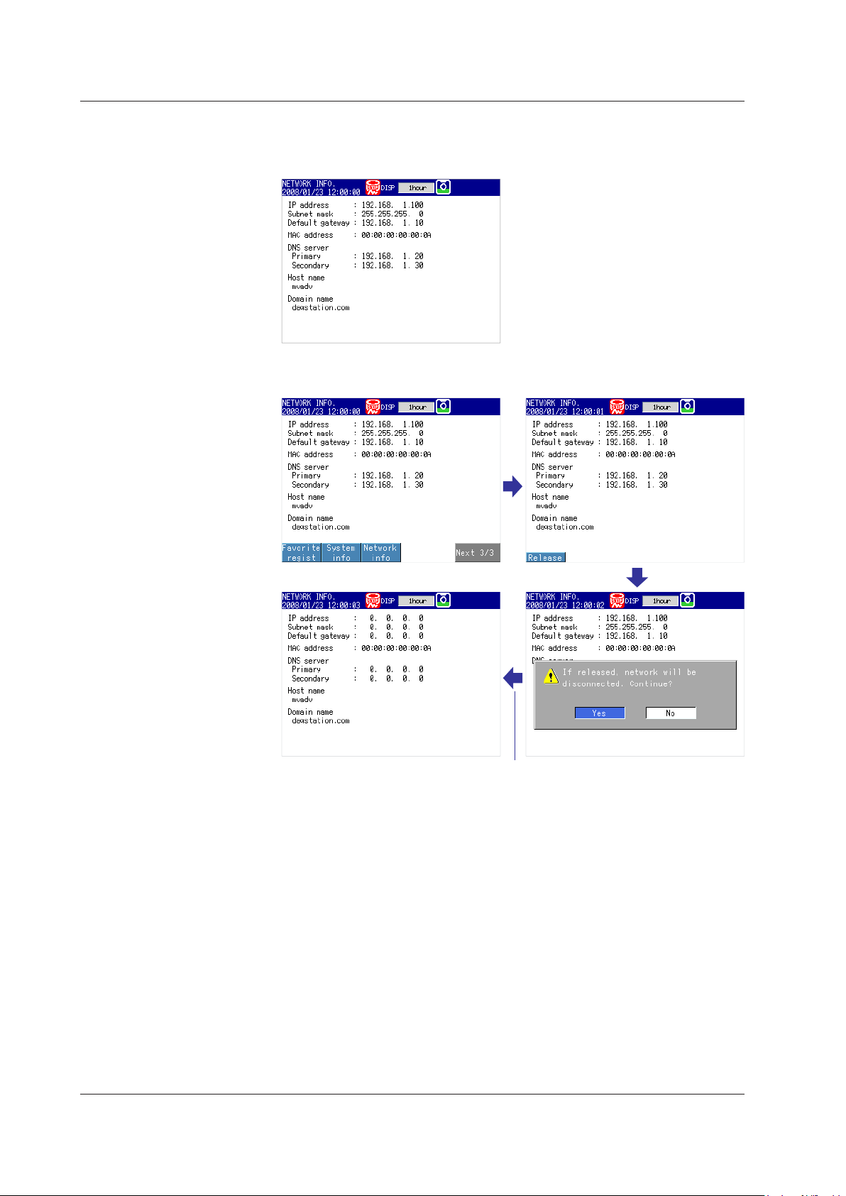
Clearing Network Information
1.
Switch to the network information screen.
◊ Press FUNC > Network info
2.
Release (clear) the network information.
◊ Press FUNC > Network info > Release
The network information is released.
DISP/ENTER key
2.2 Connecting the MV
Page 22

IM MV1000-17E
2-7
Using the Ethernet Interface
1
2
Setting the Communication Conditions
MV1000
◊ Press MENU and then select Menu tab > Basic setting mode > Menu tab >
Communication (Ethernet) > Keep alive, Timeout
MV2000
◊
Press MENU and then select Menu tab >
Basic setting mode > Menu tab >
Communication (Ethernet) > Keep alive, Application time out
Setting the Keepalive Feature
To disconnect when there is no response to the test packets that are periodically sent,
select On. Otherwise, select Off.
Setting the Application Timeout
• Selecting On or Off
To use the application timeout feature, select On. Otherwise, select Off. If you select
On, the Time parameter appears.
•
Time
Set the timeout value in the range of 1 to 120 (minutes).
Checking the Communication Status
You can check the Ethernet communication status with the LED lamp that is provided on
the MV rear panel Ethernet connector or the Ethernet link that is shown at the upper right
of the basic setting screen.
2.2 Connecting the MV
Page 23
IM MV1000-17E
2-8
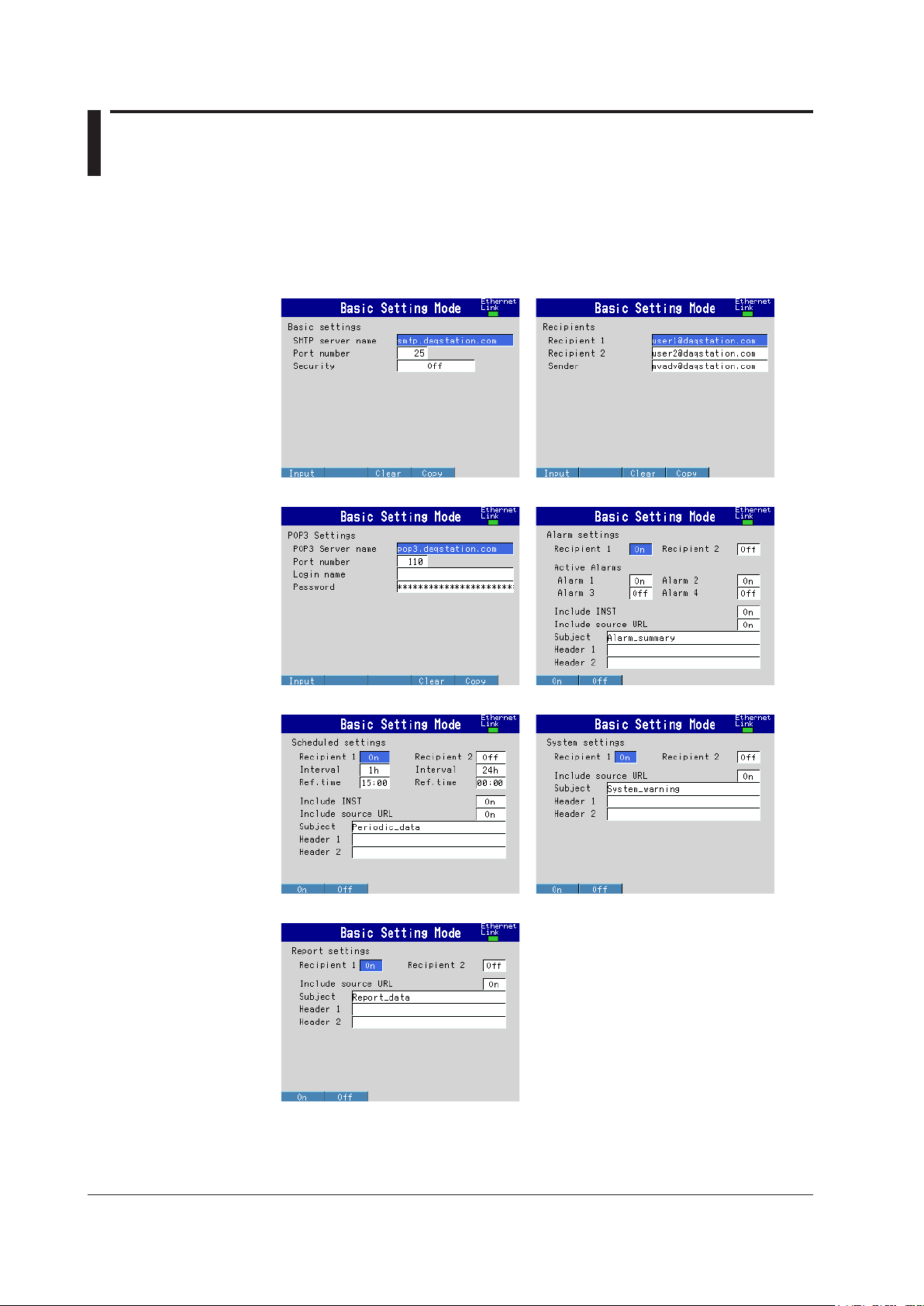
2.3 Sending E-mail Messages
Conguring E-mail Transmission
Configure the server, and set the contents of the e-mail.
◊ Press MENU and then select Menu tab > Basic setting mode > Menu tab >
Communication (Ethernet) > E-Mail
Basic settings
Recipients
POP3 Settings Alarm settings
Scheduled settings
S
ystem settings
Report settings
Page 24

IM MV1000-17E
2-9
Using the Ethernet Interface
1
2
Basic Settings
Specify the SMTP server and POP before SMTP.
• SMTP server name
Enter the host name or IP address of the SMTP server.
• Port number
Unless specified otherwise, set the number to the default value. The default value is
25.
• Security
If you need to use POP before SMTP, set Security to PbS.
Recipients
Set the recipient e-mail addresses.
• Recipient 1 and Recipient 2
Enter e-mail addresses. You can enter multiple addresses in each recipient box.
Separate each address with a space. You can enter up to 150 characters.
• Sender
Enter the sender e-mail address. You can enter up to 64 characters.
POP3 Settings
If you need to use POP before SMTP, specify the POP3 server.
For the POP3 login procedure, see “Setting the POP3 Server Connection” in this section.
• POP3 Server name
Enter the host name or IP address of the POP3 server.
• Port number
Unless specified otherwise, set the number to the default value. The default value is
110.
• Login name
Enter the POP3 server login name.
• Password
Enter the POP3 server login password. You can enter up to 32 characters.
Alarm Settings
Specify the settings for sending e-mail when alarms occur or clear.
• Recipient 1 and Recipient 2
Specify the recipients. For Recipient 1 and Recipient 2, select On to send e-mail or
Off to not send e-mail.
• Active Alarms
Sends an e-mail when an alarm occurs or clears. For alarms 1 to 4, select On to send
e-mail or Off to not send e-mail.
• Include INST
Select On to attach instantaneous value data. The data that is attached is the
instantaneous value that is measured at the time the e-mail is transmitted.
• Include source URL
Select On to attach the source URL. You can attach the URL when the Web server is
enabled.
• Subject
Enter the subject of the e-mail using up to 32 alphanumeric characters. The default
subject is Alarm_summary.
• Header 1 and Header 2
Enter Header 1 and Header 2 using up to 64 characters.
2.3 Sending E-mail Messages
Page 25

IM MV1000-17E
2-10
Scheduled Settings
Specify the settings for sending e-mail at scheduled times.
• Recipients
Specify the recipients. For Recipient 1 and Recipient 2, select On to send e-mail or
Off to not send e-mail.
• Interval
For Recipient 1 and Recipient 2, set the interval for sending e-mail to 1, 2, 3, 4, 6, 8,
12, or 24 hours.
• Ref.time
Enter the time reference for sending e-mail to Recipient 1 and Recipient 2 at a
specified interval.
• Include INST, Include source URL, Subject, Header
These parameters are the same as those listed under “Alarm Settings.” The default
subject is Periodic_data.
System Settings
Specify the settings for sending e-mail when the MV recovers from a power failure, when
there is a memory shortage, and when an error occurs.
• Recipients
Specify the recipients. For Recipient 1 and Recipient 2, select On to send e-mail or
Off to not send e-mail.
• Include source URL, Subject, and Header
These parameters are the same as those listed under “Alarm Settings.” The default
subject is System_warning.
Report Settings
Specify the settings for sending e-mail when reports are generated.
• Recipients
Specify the recipients. For Recipient 1 and Recipient 2, select On to send e-mail or
Off to not send e-mail.
• Include source URL, Subject, and Header
These parameters are the same as those listed under “Alarm Settings.” The default
subject is Report_data.
2.3 Sending E-mail Messages
Page 26

IM MV1000-17E
2-11
Using the Ethernet Interface
1
2
Setting the POP3 Server Connection
Specify the operation for connecting to the POP server.
◊ Press MENU and then select Menu tab > Basic setting mode > Environment tab >
Communication > POP3 Details
Send delay [second]
Enter the wait time from POP3 server authentication until transmission. Set a value in the
range of 0 to 10 (seconds).
POP3 Login
To send the POP3 server login password without encryption, set POP3 Login to PLAIN.
To send the password with encryption, set POP3 Login to APOP.
E-mail Test
◊ Press FUNC and then select E-mail test > Recipient1 or Recipient2
You can send a test e-mail to check the e-mail settings.
Enabling/Disabling the E-mail Transmission Function
Enabling the E-mail Transmission Function
◊ Press FUNC and then select E-Mail start
The e-mail transmission function is enabled.
Disabling the E-mail Transmission Function
◊ Press FUNC and then select E-Mail stop
The e-mail transmission function is disabled. Unsent e-mail messages are discarded.
E-mail Retransmission
If an e-mail transmission fails, the MV retransmits the message up to three times at
30-s, 1-minute, or 3-minute intervals. If retransmission fails, the MV discards the e-mail
message.
2.3 Sending E-mail Messages
Page 27

IM MV1000-17E
2-12
E-mail Format
The formats of alarm, scheduled, system, report, and test e-mails are given below.
For details on the displayed items that are common to all e-mails, see “Display Items
Common to All Formats” in this section.
Alarm Notification E-mail Format
• Subject
Subject: [Alarm Summary]
• Syntax
header1CRLF
header2CRLF
CRLF
Alarm_summary.CRLF
<Host_name>CRLF
hostCRLF
CRLF
<CH>ccc···cCRLF
<Type>lqCRLF
<aaa>mo/dd_hh:mi:ssCRLF
CRLF
<Inst._value>CRLF
mo/dd_hh:mi:ssCRLF
ccc···c=ddd···dCRLF
·····························
CRLF
Access_the_following_URL_in_order_to_look_at_a_screen.CRLF
http://host.domain/CRLF
CRLF
cc c···c
Channel number or tag name
(Up to 16 characters. Channels set to Skip or Off are not transmitted.
See section 4.3 for channel numbers.)
l
Alarm level (1 to 4)
q
Alarm type (H, L, h, l, R, or r)
H
(high limit alarm), L(low limit alarm), h(difference high limit alarm),
l
(dif
ference low limit alarm), R(high limit on rate-of-change alarm),
and r(low limit on rate-of-change alarm)
aaa
Alarm status (
off
or on)
ddd···d
Measured/computed value (up to 10 digits including the sign and
decimal point) + unit (up to six characters)
+OVER:
Positive range-out
-OVER:
Negative range-out
Burnout:
Burnout data
*****: Error data
The MV transmits the channel numbers, alarm types, and alarm statuses for up to
10 events in a single e-mail.
2.3 Sending E-mail Messages
Page 28

IM MV1000-17E
2-13
Using the Ethernet Interface
1
2
Scheduled E-mail Format
• Subject
Subject: [Periodic Data]
• Syntax
header1CRLF
header2CRLF
CRLF
Periodic_data.CRLF
<Host_name>CRLF
hostCRLF
CRLF
<Time>CRLF
mo/dd_hh:mi:ssCRLF
CRLF
E-mail_message(s)_did_not_reach_intended_recipient(s).CRLF
ttt···t
Count=nnCRLF
mo/dd_hh:mi:ssCRLF
····························
CRLF
<Inst._value>CRLF
mo/dd_hh:mi:ssCRLF
ccc···c=ddd···dCRLF
····························
CRLF
Access_the_following_URL_in_order_to_look_at_a_screen.CRLF
http://host.domain/CRLF
CRLF
cc c···c
Channel number or tag name
(Up to 16 characters. Channels set to Skip or Off are not transmitted.
See section 4.3 for channel numbers.)
ttt···t
Type of discarded e-mail
Alarm_summary:
Alarm e-mail
Periodic_data:
Scheduled e-mail
System_warning:
System e-mail
Report_data:
Report e-mail
nn
Number of discarded e-mails
ddd···d
Measured/computed value (up to 10 digits including the sign and
decimal point) + unit (up to six characters)
+OVER:
Positive range-out
-OVER:
Negative range-out
Burnout:
Burnout data
*****: Error data
The time that follows the type and count of discarded e-mails is the time when the
last e-mail is discarded.
2.3 Sending E-mail Messages
Page 29

IM MV1000-17E
2-14
System E-mail (Power Failure) Format
• Subject
Subject: [System_warning]
• Syntax
header1CRLF
header2CRLF
CRLF
Power_failure.CRLF
<Host_name>CRLF
hostCRLF
CRLF
<Power_fail>mo/dd_hh:mi:ssCRLF
<Power_on>mo/dd_hh:mi:ssCRLF
CRLF
Access_the_following_URL_in_order_to_look_at_a_screen.CRLF
http://host.domain/CRLF
CRLF
System E-mail (Memory Full) Format
• Subject
Subject: [System_warning]
• Syntax
header1CRLF
header2CRLF
CRLF
Memory_full.CRLF
<Host_name>CRLF
hostCRLF
CRLF
<Memory_remain>ppp···pMbytesCRLF
<Memory_blocks>bbb/400CRLF
<Media_remain>rrr···rMbytesCRLF
CRLF
Access_the_following_URL_in_order_to_look_at_a_screen.CRLF
http://host.domain/CRLF
CRLF
ppp···p
Remaining amount of internal memory
bbb
Number of unsaved blocks (0 to 400)
rrr···r
Remaining free space on the external storage medium (when an
external storage medium is connected)
2.3 Sending E-mail Messages
Page 30

IM MV1000-17E
2-15
Using the Ethernet Interface
1
2
System E-mail (Error) Format
• Subject
Subject: [System_warning]
• Syntax
header1CRLF
header2CRLF
CRLF
Error.CRLF
<Host_name>CRLF
hostCRLF
CRLF
mo/dd_hh:mi:ssCRLF
ERROR:fffCRLF
····························
“
Operation_aborted_because_an_error_was_found_in_media.”CRLF
CRLF
Access_the_following_URL_in_order_to_look_at_a_screen.CRLF
http://host.domain/CRLF
CRLF
fff
Error number (200, 201, 211, or 281 to 285)
The displayed error message varies depending on the error type. For details on
errors, see the
MV1000/MV2000 User’s Manual (IM MV1000-01E).
Report E-mail Format
• Subject
Subject: [Report_data]
• Syntax
header1CRLF
header2CRLF
CRLF
ti_report.CRLF
<Host_name>CRLF
hostCRLF
CRLF
mo/dd_hh:mi:ssCRLF
<CH>ccc···cCRLF
<tp>eee···eCRLF
<tp>eee···eCRLF
<tp>eee···eCRLF
<tp>eee···eCRLF
<Unit>uuu···uCRLF
····························
CRLF
Access_the_following_URL_in_order_to_look_at_a_screen.CRLF
http://host.domain/CRLF
CRLF
ti
Contents of the report e-mail (hourly
, daily, weekly, or monthly report)
cc c···c
Channel number or tag name
(Up to 16 characters. Channels set to Skip or Off are not transmitted.
See section 4.3 for channel numbers.)
2.3 Sending E-mail Messages
Page 31

IM MV1000-17E
2-16
tp
Report content (average, maximum, minimum, instantaneous, and
sum. Four out of the five items above are transmitted.)
eee···e
Measured/computed value (up to 10 digits including the sign
and decimal point). However, sum values are transmitted as a
combination of the sign, mantissa, E, sign, and exponent such as in
–3.8000000E+02.
+OVER:
Positive range-out
-OVER:
Negative range-out
Burnout:
Burnout data
Empty data: Error data
uuu···u
Unit (up to six characters)
Test E-mail Format
• Subject
Subject: [Test]
• Syntax
Test_mail.CRLF
<Host_name>CRLF
hostCRLF
CRLF
<Time>CRLF
mo/dd_hh:mi:ssCRLF
CRLF
<Message>CRLF
x:msCRLF
····························
CRLF
x
Message number (1 to 10)
ms
Message content (only specified messages are transmitted.)
Display Items Common to All Formats
• Time information
mo
Month (01 to 12)
dd
Day (01 to 31)
hh
Hour (00 to 23)
mi
Minute (00 to 59)
ss
Second (00 to 59)
The MV transmits the month, day
, hour, minute, and second in the time information
in the order specified by the date format set in Basic Setting Mode.
• Host name, domain name, and header information
header1
Header 1 (displayed only when it is set)
header2
Header 2 (displayed only when it is set)
host
Host name or IP
address (IP address when the host name is not
assigned. In the case of an IP address, the <Host> section is set to
<IP address>.)
domain
Domain name
_
Space
2.3 Sending E-mail Messages
Page 32

IM MV1000-17E
2-17
Using the Ethernet Interface
1
2
2.4 Monitoring the MV on a PC Browser
Conguring the Web Server
From the Basic Setting Mode menu, set the server function and Web page for Ethernet
communication.
Setting the Web Server
◊ Press MENU and then select Menu tab > Basic setting mode > Menu tab >
Communication (Ethernet) > Server
• Web
Set the Web parameter under Server to Use or Not (don’t use). If set to Use, Web
page parameters appear in the Basic Setting Mode menu.
Port Number
The default value is 80. To change the value:
◊ Press MENU and then select Menu tab > Basic setting mode > Environment tab >
Communication > Service port
For the selectable range, see section 7.1.
Setting the Web Page
◊ Press MENU and then select Menu tab > Basic setting mode > Menu tab >
Communication (Ethernet) > Web page
Page 33

IM MV1000-17E
2-18
Page Types (displayed screen types)
• Monitor
Configure the monitor page. The monitor page can display the following items.
• Alarm summary
• Measured and computed values of all channels
• Log (message summary, error log, etc.)
• For screen examples, see “Monitoring with a Browser” in this section.
• Operator
Configure the operator page. You can carry out the following operations in addition to the
functions available on the monitor page.
• Switch the MV display by specifying the display type (trend, historical trend, digital,
bar graph, or overview). You can also specify the trend and historical trend groups.
•
Control the MV DISP/ENTER key, arrow keys, and HISTORY
key.
• Set and write MV messages.
• For screen examples, see “Monitoring with a Browser” in this section.
Configuring the Monitor Page
• Setting the page type
To configure the monitor page, select Monitor.
• Selecting On or Off
To display the monitor page on a browser, select
On
. Otherwise, select Off.
• Setting the access control
To use access control, select
On. Y
ou must enter a user name and password to
display the monitor page. You must set the security and login in the environmental
settings to use this function. For settings, see the MV1000/MV2000 User’s Manual (IM
MV1000-01E).
Configuring the Operator Page
• Setting the page type
To configure the operator page, select Operator.
• Setting the access control
This setting is the same as that for the monitor page.
• Selecting whether or not to use command input
To use the set and write commands for messages, select
On. Otherwise, select
Off.
2.4 Monitoring the MV on a PC Browser
Page 34

IM MV1000-17E
2-19
Using the Ethernet Interface
1
2
Monitoring the MV on a Browser
Setting the URL
Set the URL appropriately according to your network environment. You can access the
MV by setting the URL as follows:
http://host name.domain name/file name
• http: The protocol used to access the server.
• Host name.domain name:
The MV host name and domain name.
You can also use an IP address in place of the host name and domain name.
• File name: The file name of the MV monitor page or operator page.
File name of the monitor page: monitor.htm
File name of the operator page: operator.htm
Omitting the file name is equivalent to specifying the monitor page. However, if the
monitor page is disabled, it is equivalent to specifying the operator page.
Example
To display the operator page on a PC that is in the same domain as the MV, enter
the URL in the browser Address box as follows:
http://mv1000.daqstation.com/operator.htm or
http://192.168.1.100/operator.htm
(In this example, we assume that the domain name is daqstation.com, the host
name is mv1000, and the IP address is 192.168.1.100.)
Login
Enter the user name and login password. You do not have to enter these items if access
control is set to Off in the Web page setting.
• Monitor Page Contents
MV screen image
The displayed information is the same as that shown on the MV.
Automatically refreshes the screen
Turn this ON to automatically refresh
the screen.
All channel display
Displays measured values and alarm statuses
of all channels in a separate window.
Log display
Displays each log in a separate
window.
Refresh the screen
Display the alarm summary
Displays an alarm summary
in a separate window.
Zoom
Changes the zoom rate of
the screen.
MV1000: 100% and 200%
MV2000: 50% and 100%
Data list and print page
Displays the information in
a separate window.
2.4 Monitoring the MV on a PC Browser
Page 35

IM MV1000-17E
2-20
• If the MV is in Setting Mode* or Basic Setting Mode*, the monitor page cannot be
displayed. An error message will appear.
*
For details on modes, see the MV1000/MV2000 User’s Manual (IM MV1000-01E).
• Refreshing the monitor page
The monitor page can be refreshed automatically or manually.
•
Auto Refresh ON
The monitor page is refreshed at approximately 10-second intervals.
• Auto Refresh OFF
The monitor page is not automatically refreshed. You can refresh the page
manually
. The page will not be refreshed within approximately 10 seconds for the
last refreshing even if you try to refresh the page manually.
• Displaying the log
You can display the message summary
, error log, FTP log, login log, Web operation
log, e-mail log, SNTP
log, and Modbus log in a separate window. From the Log list,
select the log you want to display. Click Refresh to refresh the data. The window can
display up to 100 messages and 50 added messages.
Log display (example of a message log display)
• Refreshing the alarm summary display and all channel display
Click Refresh to refresh the data. The alarm summary can display up to 400 alarms.
Example of an alarm summary display
Example of an all channel display
2.4 Monitoring the MV on a PC Browser
Page 36

IM MV1000-17E
2-21
Using the Ethernet Interface
1
2
• Data list
You can easily retrieve files via FTP from the data list link without having to specify the
URL. You can also save the data that is being sampled to a file and retrieve the file.
For the procedure, see section 2.5.
• Print page
You can enter a title and comments in the screen image and print the image.
Title box
By default, the title box displays
the IP address or host name.
You can overwrite the default
title with your own.
Comment input box
Enter comments.
You can enter more than five
lines of comments, but only
the first five lines will be printed.
2.4 Monitoring the MV on a PC Browser
Page 37

IM MV1000-17E
2-22
• Operator Page Contents
MV screen image
The displayed information is
the same as that shown on
the MV.
Selects the trend screen
Directly selects the group you
want to display.
Data list and print page
Displays the information in a
separate window.
Automatically refreshes the screen
All channel
display
Log
display
Message input
Opens a separate window for
entering a message.
Refreshes
the screen
Displays the alarm summary
Zoom
Selects the historical display
Directly selects the group you
want to display.
Selects other displays
Selects the overview display,
numeric display, or bar graph
display.
HISTORY key
Performs the same operation
as the corresponding key on
the MV.
Arrow keys and DISP key
Performs the same operations
as the corresponding keys on
the MV.
You can carry out the following operations on the operator page in addition to the
operations available on the monitor page.
•
Switch between trend, historical trend, digital, bar graph, and overview displays.
For the trend and historical trend displays, you can switch the MV screen by specifying
the group you want to display.
• Control the MV using the DISP/ENTER key, arrow keys, and HISTORY
key on the
operator page.
You can carry out the same operations as the DISP/ENTER key, arrow keys, and
HISTOR
Y key on the MV.
• Set and write messages
You can set a message string to MV messages 1 through 10 (up to 32 alphanumeric
characters) and, at the same time, write it to the specified group. The existing
message is overwritten.
The following figure indicates an example in which the word
“ALARM” is written to all groups in message number 9, and the Command Response
box shows that the operation has been successfully completed.
Message entry example
2.4 Monitoring the MV on a PC Browser
Page 38

IM MV1000-17E
2-23
Using the Ethernet Interface
1
2
2.5 Accessing Measured Data Files on the MV from a PC
You can access data files stored on an external storage medium.
Conguring the FTP Server
◊ Press MENU and then select Menu tab > Basic setting mode > Menu tab >
Communication (Ethernet)> Server
• FTP
Set the FTP parameter under Server to Use or Not (don’t use).
Accessing the MV from a PC
You can use the following functions when the FTP server is enabled.
Accessing a Data File from a Web Page
• If the Data File to Be Retrieved Is Already Generated
1.
Click the Data list link.
2.
Click Memory or Media.
3.
Select the file you want to retrieve from the file list.
4.
Drag and drop the file to the desired folder on the PC.
Note
• The Internal memory link is ftp://hostname/MEM0/DATA.
• The External media link is ftp://hostname/DRV0/.
Page 39

IM MV1000-17E
2-24
• If the Data File to Be Retrieved Is Being Generated
1.
Click the Data list link.
2.
Click OK for retrieving the most recent data.
The
Confirmation
window opens.
3.
Read the information, and click OK.
4.
In the File status window, click Update.
If the file has been generated, the Final status window opens. If not, the File status window
will open. Wait for a little while, and click
Update
again.
5.
In the Final status window, click Get.
6.
In the File Download window, click Save.
Note
• You can retrieve files by carrying out the steps above when the data file contains display
data or event data stored in Free mode.
• The file is generated at different times from the specified file save interval.
Connecting to the MV from a PC via the FTP
An example of retrieving files using a browser is described below. In the Address box,
enter the following:
ftp://host name.domain name/file name
To retrieve data from the internal memory, drag the files from the /MEM0/DAT
A folder. To
retrieve data from an external storage medium, drag the files from the /DRV0 folder. You
can also use an IP address in place of the host name and domain name.
You can also retrieve files easily from the Data list link in the browser window. See
section 2.4 for details.
Login
If the security feature is enabled, you will be prompted for a login name and password.
Enter the login name and password to connect to the server.
Port Number
The default value is 21. To change the value:
◊ Press MENU and then select Menu tab > Basic setting mode > Environment tab >
Communication > Service port
For the selectable range, see section 7.1.
2.5 Accessing Measured Data Files on the MV from a PC
Page 40

IM MV1000-17E
2-25
Using the Ethernet Interface
1
2
2.6 Transferring Data Files from the MV
The MV can automatically transfer display and event data files, report data files, and
snapshot data files that are created in the MV internal memory via FTP as the files are
created.
Files to Be Transferred via FTP
The MV automatically transfers display and event data files and report data files to the
FTP destination at appropriate times.
File Type Description
Display data file Automatically transferred at the file save interval.
Event data file Automatically transferred each time the specified length of data is recorded.
Report data file Automatically transferred when a report file is closed (divided). For
example, a data file is transferred once per month if you configure the MV
to generate only daily reports.
Snapshot data file Automatically transferred when you take a snapshot.
*
Snapshot data files
are transferred regardless of the media storage settings.
* Snapshots taken using the FUNC key, the EV2 communication command,
the USER key, or the remote control function.
Conguring the FTP Client
◊ Press MENU and then select Menu tab > Basic setting mode > Menu tab >
Communication (Ethernet) > FTP client
FTP
transfer file settings FTP connection settings
Specifying the Files to be Transferred via FTP
• Disp&Event Data
Select On to automatically transfer display and event data files.
• Report
Select On to automatically transfer report data files.
• Snapshot
Select On to automatically transfer snapshot data files.
Page 41

IM MV1000-17E
2-26
Setting the FTP Connection Destination
Set the primary and secondary FTP servers, port number, login name, password,
account, PASV mode, etc. Consult your network administrator for the correct values.
• FTP connection
You can specify two destination FTP servers: primary and secondary. If the primary
FTP server is down, the file is transferred to the secondary FTP server.
• Server name
Enter the name of the destination FTP server using up to 64 alphanumeric characters.
• If you are using the DNS, you can set the host name for the server name. For DNS
settings, see section 2.2.
• You can also set the IP address. In this case, the DNS is not required.
• Port number
Enter the port number of the destination FTP server in the range of 1 to 65535. The
default value 21.
• Login name
Enter the login name for accessing the FTP server using up to 32 alphanumeric
characters.
• Password
Enter the password for accessing the FTP server using up to 32 alphanumeric
characters. The characters that you enter will be displayed as
*****
.
• Account
Enter the account ID for accessing the FTP server using up to 32 alphanumeric
characters.
• PASV mode
Select On when using the MV behind a firewall that requires the passive mode. The
default setting is Off.
• Initial path
Set the file transfer destination directory using up to 64 alphanumeric characters. The
delimiter for directories varies depending on the implementation of the destination FTP
server.
Example:
When transferring files to the “data” directory in the “home” directory of an
FTP server on a UNIX file system.
/home/data
If the file transfer to both primary and secondary destinations fails, the MV will abort the
file transfer. When the connection recovers, the MV will transfer the data that could not to
be transferred along with the new data file. However, because the data that could not be
transferred resides in the MV internal memory
, the data will be lost if it is overwritten.
2.6 Transferring Data Files from the MV
Page 42

IM MV1000-17E
2-27
Using the Ethernet Interface
1
2
Testing the FTP Transfer
You can transfer a test file from the MV to an FTP server.
◊ Press FUNC > FTP test
Items to Check Before Executing This Test
• Connect the Ethernet cable properly. For the connection procedure, see section 2.2.
• Check that the Ethernet interface settings are correct. For the setup procedure, see
section 2.2.
Viewing the FTP Test Result
• When you execute an FTP test, the MV transfers a test file named FTP_TEST.TXT to
the FTP connection destination initial path directory that you specified in this section.
• You can check the FTP test result on the FTP log (displayed o
n the MV (see the
User’s Manual), displayed on the Web screen (see section 2.4), or transmitted with
the FL command (see section 4.8)).
2.6 Transferring Data Files from the MV
Page 43

IM MV1000-17E
2-28
2.7 Synchronizing the Time
The MV time can be synchronized to the time on an SNTP server. You can also configure
the MV to run as an SNTP server.
Conguring the SNTP Client
You can configure the SNTP client to synchronize the MV time to an SNTP server.
◊ Press MENU and then select Menu tab > Basic setting mode > Menu tab >
Communication (Ethernet) > SNTP client
• Use/Not
To use the SNTP client function, select Use. Otherwise, select Not. If you select Use,
the SNTP client parameters appear.
• Server name
Enter the SNTP server name using up to 64 alphanumeric characters.
• If you are using the DNS, you can set the host name for the server name. For DNS
settings, see section 2.2.
• You can also set the IP address. In this case, the DNS is not required.
• Port number
Enter the SNTP server port number in the range of 1 to 65535. The default value is
123.
• Access interval
Set the time interval for synchronizing the time with the server to Off, 1, 8, 12, or 24h.
If you select Off, you can synchronize the time using the soft keys. The time is not
synchronized if the time difference between the MV and the server is greater than or
equal to 10 minutes.
• Access reference time
Set the reference time for making queries.
• Access timeout
Set the time that the MV will wait for a response from the SNTP server after making a
query to 10, 30, 90 s.
• Time adjust on Start action
Select On to synchronize the time with an SNTP server when memory start is
executed. Otherwise, select Off.
Manually Synchronizing the Time
You can synchronize the time at any time using the FUNC key. The SNTP client setting
must be enabled.
◊ Press FUNC > SNTP
Page 44

IM MV1000-17E
2-29
Using the Ethernet Interface
1
2
Conguring the SNTP Server
You can configure the MV to run as an SNTP server.
◊ Press MENU and then select Menu tab > Basic setting mode > Menu tab >
Communication (Ethernet) > Server
• SNTP
Set the SNTP parameter under Server to Use or Not (don’t use).
When an SNTP client on the network queries the MV for the time information, the MV
returns the time information.
Port Number
The default value is 123. To change the value:
◊ Press MENU and then select Menu tab > Basic setting mode > Environment tab >
Communication > Service port
For the selectable range, see section 7.1.
2.7 Synchronizing the Time
Page 45

IM MV1000-17E
2-30
2.8 Reading/Writing the MV Data from Another Device via Modbus
The MV is a Modbus server.
For Modbus specifications, see section 7.3.
Conguring the Modbus Server
You can configure the Modbus server so that another device will be able to read or write
the MV data via Modbus.
◊ Press MENU and then select Menu tab >
Basic setting mode > Menu tab >
Communication (Ethernet) > Server
• Modbus
Set the Modbus parameter under Server to Use. If you select Not (not use), you will
not be able to use the Modbus server function.
Port Number
The default value is 502. To change the value:
◊ Press MENU and then select Menu tab > Basic setting mode > Environment tab >
Communication > Service port
For the selectable range, see section 7.1.
Reading or Writing the MV Data from Another Device
Another device (client device) sends commands to the MV to read data from the MV or
write data to the MV.
For the function codes that the MV supports and the MV registers that the client device
can access, see “Modbus Server Function” in section 7.3.
Specifying the Register Number
Specify the MV register on the client device according to the instructions below.
•
If you are using a commercial SCADA system or something similar, specify the
register number (a number such as 400001; referred to as the “reference number”)
listed under Modbus Server Function in section 7.3, “Modbus Protocol Specifications.”
• If you are using a custom communication program, specify the
“relative number”
in relation to the reference number. Compute the relative number in the manner
indicated in the examples below.
Examples
The relative number for input register 300100 is 99, which is the dif
ference between
300100 and 300001.
300100 – 300001 = 99
The relative number for input register 400011 is 10, which is the difference between
400011 and 400001.
400011 – 400001 = 10
Page 46

IM MV1000-17E
2-31
Using the Ethernet Interface
1
2
2.9 Reading/Writing Data on Another Device from the MV via Modbus
The MV is a Modbus client.
For Modbus specifications, see section 7.3.
Conguring the Modbus Client
You can configure the Modbus client so that the MV will be able to read or write data to
another device via Modbus.
◊ Press MENU and then select Menu tab >
Basic setting mode > Menu tab >
Communication (Ethernet) > Modbus client
Basic settings
Destination server settings
Transmission command settings
Basic Settings
• Read cycle
Set the read cycle to 125m, 250m, 500m, 1s, 2s, 5s, or 10s.
• Retry interval
Set the interval for retrying the connection when the connection is interrupted for
some reason. Select Off, 10s, 20s, 30s, 1min, 2min, 5min, 10min, 20min, 30 min,
or 1h. If you select Off, the MV will not retry the connection. If communication fails,
communication will stop.
Page 47

IM MV1000-17E
2-32
Destination Server Settings
• Server number
Select registration numbers of the server you want to configure from 1 to 16.
• Port
Enter the port number for the selected server in the range of 0 to 65535. The default
value is 502.
• Modbus server name
Set the destination Modbus server name using up to 64 alphanumeric characters.
• If you are using the DNS, you can set the host name for the server name.
• You can also set the IP address. In this case, the DNS is not required.
• Unit
If the unit number of the destination server is not necessary, select Auto. If a fixed unit
number is necessary, select Fixed. If you select Fixed, the unit number parameter
appears.
• No.
Enter a fixed unit number in the range of 0 to 255.
Transmission Command Settings
• Client command number
Select numbers of the transmission commands you want to configure from 1 to 16.
• Command type
Set the command type to Off, R, R-M, W, or W-M. If you select a command type
other than Off, the client channel, server number, register, and data type parameters
appear.
R:
Read the data from the server into external input channels (16-bit signed
integer)
R-M:
Read the data from the server into communication input channels (32-bit
floating point)
W:
Write measurement channel data (16-bit signed integer) to the server
W
-M: Write computation channel data (32-bit signed integer) to the server
R is selectable on the MV2000 when external input channels (/MC1 option) is installed.
R-M and W-M are selectable when the computation function (/M1 option) is installed.
• First/Last (MV channels)
Enter the first and last channel numbers of input/output. The range of channels that
you can enter varies depending on the command type as follows:
R: 201 to 440, R-M: C01 to C60, W: 1 to 48, W-M: 101 to 160
• Server (server number)
Select a server number from 1 to 16.
• Regi. (server register)
Set the server register number.
Enter an input register in the range of 30001 to 39999 and 300001 to 365536 or a hold
register in the range of 40001 to 49999 and 400001 to 465536.
The register numbers that you can specify vary depending on the command type. See
section 7.3 for details.
• Type
The data type.
Select INT16, UINT16, INT32_B, INT32_L, UINT32_B, UINT32_L, FLOAT_B, or
FLOAT_L.
The data type that you can specify vary depending on the command type. See section
7.3 for details.
2.9 Reading/Writing Data on Another Device from the MV via Modbus
Page 48

IM MV1000-17E
2-33
Using the Ethernet Interface
1
2
Examples of Entering Commands
The following are examples of commands when the MV is operating as a Modbus client
device. If the MV is operating as a Modbus master device, read the word “client” as
“master” and “server” as “slave.”
Ethernet
MVAdvanced
(Modbus client)
Instrument A
(Modbus server 1)
Instrument B
(Modbus server 2)
Instrument C
(Modbus server 3)
Connection example
Loading Data into Communication Input Channels
The MV reads the data from the server device and enters the data into communication
input channels in floating point format.
• Example 1
Read a 16-bit signed integer value from instrument A’s register 30001 into C01.
C01 30001
Communication input data
Instrument A register
16-bit signed integer
Command
R-M C01 - C01 1 30001 INT16
• Example 2
Read a 32-bit signed integer value from instrument B’s registers 30003 and 30004
(lower bytes and higher bytes) into C03. Specify the smaller register number in the
command.
30003 Lower bytes
Higher bytes
30004
C03
32-bit signed integer
Instrument B register
Communication input data
Command
R-M C03 - C03 2 30003 INT32_L
• Example 3
Read a 16-bit signed integer value from instrument B’s registers 30001 and 30002 into
C01 and C02. Specify the smaller register number in the command.
30001 16-bit signed integer
16-bit signed integer
30002
C01
C02
Instrument B register
Communication input data
Command
R-M C01 - C02 2 30001 INT16
• Example 4
Read a 32-bit floating point value from instrument B’s registers 30005 and 30006
(lower bytes and higher bytes) into C04. Specify the smaller register number in the
command.
30005 Lower bytes
30006
C04
32-bit floating point
Instrument B register
Communication input data
Higher bytes
Command
R-M C04 - C04 2 30005 FLOAT_L
2.9 Reading/Writing Data on Another Device from the MV via Modbus
Page 49

IM MV1000-17E
2-34
Reading Data into External Input Channels (MV2000 only)
The MV reads the data from the server device and enters the data into external input
channels in 16-bit signed integer format.
• Example 1
Read a 16-bit unsigned integer value from instrument C’s register 30001 into external
input channel 201.
30001
201
16-bit unsigned integer
External input channel
Instrument C register
Command
R 201 - 201 3 30001 UINT16
• Example 2
Read a 32-bit unsigned integer value from instrument C’s register 32001 and 32002
into external input channel 202. Specify the smaller register number in the command.
32-bit unsigned integer
32001
32002
202
External input channel
Instrument C register
Higher bytes
Lower bytes
Command
R 202 - 202 3 32001 UINT32 _ B
Writing Measured Values to a Server
• Example
Write the measured value of channel 1 (16-bit signed integer) to instrument A’s
register 40001.
16-bit signed integer
Measurement channel
Instrument A register
001 40001
Command
W 001 - 001 1 40001 INT16
Writing Computed Values to a Server
• Example
Write the computed value of channel 101 (32-bit signed integer) to instrument A’s
40001 and 40002 registers, lower 16 bits first and then higher 16 bits. Specify the
smaller register number in the command.
32-bit signed integer
Computation channel
Instrument A register
101
Lower bytes
Higher bytes
40001
40002
Command
W-R 101 - 101 1 40001 INT32_L
2.9 Reading/Writing Data on Another Device from the MV via Modbus
Page 50

IM MV1000-17E
2-35
Using the Ethernet Interface
1
2
Checking the Modbus Operating Status
Displaying the Modbus Operating Status
◊ Press DISP/ENTER and then select INFORMATION > MODBUS CLIENT
Note
To show the MODBUS CLIENT on the display selection menu, you need to change the setting
using the menu customize feature. Carry out the following steps.
◊ Press
MENU and then select Menu tab >
M
enu customize > Display menu
1. Select
INFORMATION > MODBUS CLIENT using the arrow keys.
2.
Press the V
iew
soft key
.
Server device host names or IP addresses
Register numbers
MV channels
Detail code
Status lamp
Cursor used to select a command
(Used to resume command transmission from the front panel keys)
Communication conditions
• Communication Conditions
The Read cycle and Connect.retry settings are displayed.
• Communication Status
The MV displays the communication status using status lamps and detail codes.
Status Lamp
Detail Code Meaning
Green Good Communication is operating normally.
Yellow Command is readying.
Orange Trying to establish a TCP connection.
Red Communication is stopped.
Common to yellow,
orange, and red
None
No response from the server device.
Func
The server device cannot execute the command from the MV.
Regi
The server device does not have the specified register.
Err
There is an error in the response data from the server device.
Link Ethernet cable is disconnected.
Host Unable to resolve the IP address from the host name.
Cnct Failed to connect to the server.
Send Failed to transmit the command.
BRKN Failed to receive the response data or detected a
disconnection.
(Space) The detail code does not appear until the status is
confirmed when communication is started.
2.9 Reading/Writing Data on Another Device from the MV via Modbus
Page 51

IM MV1000-17E
2-36
Resuming Command Transmission
Using the front panel keys, you can resume command transmission to a server device
whose communication is stopped (red status lamp).
1. Using the up and down arrow keys, select the command assigned to the server
device that you want to resume transmission. The message “Push [right arrow] key to
refresh” appears.
2. Press the right arrow key
. The MV will transmit a command to the specified server.
Data When Communication Is Stopped and during Connection Retrials
If command transmission stops such as when the connection is disconnected, the
status lamp will turn orange or red, and the communication input data and external input
channel data will be error data. For computation channels, the MV displays “+OVER” or “–
OVER” according to the settings. The MV displays “******” for external input channels.
Data Dropout
A data dropout occurs when the commands 1 to 16 do not complete within the read cycle
(see appendix 2). When a data dropout occurs, the communication input data is held at
the previous value. The Modbus operating status display shows a message indicating
that a data dropout occurred. If this happens, take measures such as making the read
cycle longer or reducing the number of commands. Be sure to confirm that no data
dropout occurs on the Modbus status log display.
2.9 Reading/Writing Data on Another Device from the MV via Modbus
Page 52

IM MV1000-17E
2-37
Using the Ethernet Interface
1
2
Function for Automatically Assigning MW100s to the Modbus Client (MV2000
only)
The following setup is carried out from the MV using YOKOGAWA MW100 Data
Acquisition Unit as a Modbus server.
If the MV2000 is a Modbus client, MW100s—Modbus servers on the network—can be
automatically assigned to the MV2000. This feature is available only on MV2000s with
the external input channel function (/MC1 option).
Setup Preparation
Configure the MW100s so that they are ready to make measurements (IP address,
system construction, range setting, and the like of the MW100s that are going to be
automatically assigned). For details, see the MW100 User’s Manual.
Setup Procedure
If the MV IP address is not set, set it before carrying out the procedure below.
1.
Press MENU and then select Menu tab > Basic setting mode > Menu tab >
Communication (Ethernet) > Modbus client > Auto setting.
2.
Carefully read the displayed precautions. Select Yes to execute the auto setting.
Select No to return to the screen operation.
3.
From the list of MW100s that is displayed, select the MW100s to be connected
using the up and down arrow keys, and press DISP/ENTER. The selected
MW100s are assigned to the external input channels of the MV.
Displays the IP address or host name.
Displays the MW100 unit number. The list displays up to
16 units in order from the smallest unit number.
Pressing the Call soft key causes “--” to blink for 2 seconds on the 7-segment LED
display of the selected MW100.
This feature allows you to check which MW100 is selected if multiple MW100s are connected.
Displays the status of the external input
channel assignments.
No settings: The MW100 is not automatically
assigned.
Not Ready: The MW100 cannot be connected.*
A value: Displays the number of the
assigned external input channel
Example: If an MW100 is assigned
to external input channels
201 to 220, the status
displays 201/220.
To correct the problem, see the
MV1000/MV2000 User’s Manual.
2.9 Reading/Writing Data on Another Device from the MV via Modbus
Page 53

IM MV1000-17E
2-38
Settings
The MW100 channels are assigned to the MV external input channels as follows:
• Channel numbers
The channels of the MW100 selected first are assigned consecutively to external
input channels from 201. The channels of the MW100 selected next are assigned
consecutively to the available external input channels from the smallest number. You
cannot select the target external input channels.
MW100
Measurement channels
CH001 to CH020
Measurement channels
CH001 to CH004,
CH011 to CH014
Measurement channels
CH001 to CH030
Automatic
assignment
order
MV
MV external
input channels
MW100
MW100
CH201
CH220
CH221
CH240
CH241
CH270
MW100
measurement
channels
CH001
CH020
CH001
CH014
CH001
CH030
1
2
3
MW100
• Range settings
The range settings of the MW100 (including the span and unit) are set automatically
to the external input channels.
If the span setting of the MW100 range exceeds the span setting range of the MV
external input channel (–30000 to 30000), it is set to the span upper limit (30000) or
lower limit (–30000).
Specify the settings such as the alarm, the tag, and the area display of the color scale
band of each channel after the auto setting is complete.
Note
Precautions When Assigning Channels to the External Input Channels
• The MW100 channels are assigned 10 channels at a time to the external input channels. If
the MW100 measurement module consists of less than 10 channels, “OFF” is assigned to
the external input channels for the section without channels.
• An error occurs if the number of MW100 channels to be automatically assigned is greater
than the number of available external input channels.
• If the range setting of a MW100 channel is set to “SKIP,” the corresponding MV external
input channel is set to “OFF.”
• If a MW100 unit contains a module that cannot be assigned automatically, only the channels
that can be assigned are assigned to the MV external input channels.
• If a new MW100 is added, auto setting is executed again. Because all the settings are
cleared, you must execute auto setting again for all MW100s.
• If you are connecting MW100s that can be automatically assigned along with MW100s
that cannot be automatically assigned or other Modbus devices, automatically assign the
MW100s that can be automatically assigned first and then manually assign the remaining
devices.
2.9 Reading/Writing Data on Another Device from the MV via Modbus
Page 54

IM MV1000-17E
2-39
Using the Ethernet Interface
1
2
Note
About the MW100
• MW100s that support auto assignment are those with firmware version R2.22 or later.
• MW100 modules that can be automatically assigned are the following input modules. The
installable input modules vary depending on the MW100 firmware version.
4-CH, High-Speed Universal Input Module
10-CH, Medium-Speed Universal Input Module
6-CH, Medium-Speed Four-Wire RTD Resistance Input Module
10-CH, High-Speed Digital Input Module
30-CH, Medium-Speed DCV/TC/DI Input Module
10-CH, Medium-Speed Pulse Input Module
• If there are no assignable channels or the Modbus server setting is Off, auto setting fails
with an error. Check the settings.
• MW100s that are connected through auto setting automatically switches to the measurement
mode.
• MW100 port number 34324 is used to perform auto setting.
• For details on the MW100 settings, see the MW100 User’s Manual.
The first channel information of the MW100 that is automatically assigned to an external
input channel can be displayed when the cursor is on the first or last channel.
In addition, you can check the status of the connected MW100 on the Modbus status
display screen.
2.9 Reading/Writing Data on Another Device from the MV via Modbus
Page 55

IM MV1000-17E
2-40
2.10 Usage Example of the Modbus Function
This section explains an example of setting two MV1000s that are connected via the
Ethernet network, one configured to be a Modbus client and another configured to be a
Modbus server. This section refers to the MV1000 configured to be a Modbus server as
the MV1000 server and the MV1000 configured to be a Modbus client as the MV1000
client.
System Conguration and Operation
The measurement channels, computation channels, and communication input data
shown below will be used. We assume that the Ethernet interface is already configured.
MV1000 server
(Modbus server)
Ethernet
Measured data
Command
Reads measured data from the MV1000
and displays data on a computation
channel (/M1 option).
MV1000 client
(Modbus client)
Measurement channel 1
Input range: –2.000 to 2.000 V
Computation channel 101
–2.000 to 2.000 V
Communication input data C01
Modbus service port
502 (default value)
Start the computation
Displayed in group 1
Server number: 1
Operation
• The MV1000 client reads the measured value from the MV1000 server channel 1 into
communication input channel C01 and displays the value on computation channel
101. The MV displays computation channel 101 in group 1.
•
The measured value of MV1000 server channel 1 is transferred to the MV1000 client
as an integer in the range of –20000 to 20000.
• The MV1000 client displays values in the range of –2.0000 to 2.0000 V for values
in the range of –20000 to 20000. The value is linearly scaled using the following
equation.
The value on MV1000 client computation channel 101 = Communication input data
C01 × 0.0001
Page 56

IM MV1000-17E
2-41
Using the Ethernet Interface
1
2
Conguring the MV1000 Server (Modbus server)
Configuring the Modbus Server Function
◊ Press MENU and then select Menu tab > Basic setting mode > Menu tab >
Communication (Ethernet) > Server
Parameter Setting
Modbus Use
Port Number
The default value is 502.
Configuring Measurement Channels
◊ Press MENU and then select Menu tab > Meas channel > Range, Alarm
Parameter Setting
First channel and last channel 1
Mode Volt
Range 2V
Span_L –2.0000
Span_U 2.0000
2.10 Usage Example of the Modbus Function
Page 57

IM MV1000-17E
2-42
Conguring the MV1000 Client (Modbus client)
The description below assumes that settings other than destination server settings and
commands are at default values.
Registering the Destination Server
The example below describes the settings used to register the MV1000 server to number 1.
The MV1000 server IP address is assumed to be 192.168.1.101.
◊ Press MENU and then select Menu tab >
Basic setting mode > Menu tab >
Communication (Ethernet) > Modbus client > Modbus server settings
Parameter Setting
Port 502
Modbus server name 192.168.1.101
Unit Auto
Setting Transmission Commands
◊ Press MENU and then select Menu tab > Basic setting mode > Menu tab >
Communication (Ethernet) > Modbus client > Command settings
Parameter Setting
Command type R-M
First and Last C01
Server 1
Regi. 30001
Type INT16
2.10 Usage Example of the Modbus Function
Page 58

IM MV1000-17E
2-43
Using the Ethernet Interface
1
2
Configuring Computation Channels
◊ Press MENU and then select Menu tab > Math channel > Expression, Alarm
Parameter Setting
First and Last 101
Math On
Calculation expression 01*K01
Span Lower –2.0000
Span Upper 2.0000
Unit V
◊ Press MENU and then select Menu tab > Math channel > Constant
Parameter Setting
Number of constant K01
Value 0.0001
Assigning a Channel to a Group
◊ Press MENU and then select Menu tab > Group set, Trip line
Parameter Setting
Group number 1
On/Off On
Group name GROUP 1
CH set 101
2.10 Usage Example of the Modbus Function
Page 59

IM MV1000-17E
2-44
Starting Computation (MV1000 client)
◊ Press FUNC > Math start
Computation starts, and the status display section shows the math icon.
The v
alue of the MV1000 client’s computation channel 101 shown in GROUP 1 varies
in sync with the measured value of the MV1000 server’s measurement channel 1.
Checking the Modbus Operating Status (MV1000 client)
Showing the Menu Used to Switch to the Modbus Client Screen
Carry out the procedure below to show INFORMATION > MODBUS CLIENT in the
display selection menu.
◊ Press MENU and then select Menu tab >
Menu customize > Display menu
1.
Select INFORMATION > MODBUS CLIENT using the arrow keys.
* Select MODBUS MASTER to use Modbus master via the serial interface.
2.
Press the View soft key.
The menu item is enabled and is displayed in white.
View/Hide
Pressing the View soft key changes
the soft key to Hide.
3.
Press ESC several times to return to the operation screen.
Displaying the Modbus Client Screen
◊ Press DISP/ENTER and then select INFORMATION > MODBUS CLIENT
* Select INFORMATION > MODBUS MASTER to use Modbus master via the serial
interface.
2.10 Usage Example of the Modbus Function
Page 60

3-1
IM MV1000-17E
Using the Serial Interface
1
2
3
3.1 Workflow for Using the Serial Interface
The flow chart below shows the procedure to set RS-232 or RS-422/RS-485
communication.
The procedure differs between RS-232 and RS-422/RS-485.
Set the address
RS-232
RS-422/485
Set the parity
Set the data length
Set the baud rate
Connect a cable
Set the handshaking
Communication type
Configure the
Modbus master
Set the protocol
Configuration required when the protocol
is set to Modbus master.
Start
End
Chapter 3 Using the Serial Interface
Page 61

3-2
IM MV1000-17E
3.2 Connecting the MV
Connecting a Cable
Connect a cable to the serial port on the MV rear panel.
RS-232 Connection Procedure
Connect a cable to the 9-pin D-sub RS-232 connector.
Connector Pin Arrangement and Signal Names
1 2 3 4 5
6 7 8 9
(Rear panel)
Pin assignments are shown in the table below.
The table shows the signal names as defined by the RS-232 , JIS, and ITU-T
standards along with their description.
Pin Signal Name Name Signal Description
JIS ITU-T RS-232
2 RD 104 BB(RXD) Received data Input signal to the MV.
3 SD 103 BA(TXD) Transmitted
data
Output signal from the MV.
5 SG 102 AB(GND) Signal ground Signal ground.
7 RS 105 CA(RTS) Request to
send
Handshaking signal transmitted
from the MV used to receive data
from the PC.
8 CS 106 CB(CTS) Clear to send Handshaking signal transmitted
from the MV used to receive data
from the PC.
* Pins 1, 4, 6, and 9 are not used.
Connection
• Signal direction
PC MV
RS [Request to send...Ready to receive]
SD [Send data]
RD [Received data]
2
3
8
7
CS [Clear to send...Ready]
Page 62

3-3
IM MV1000-17E
Using the Serial Interface
1
2
3
• Connection example
SD
RD
RS
CS
SG
SD
RD
RS
SG
• OFF-OFF/XON-XON
PC MV
SD
RD
RS
CS
SG
SD
RD
RS
SG
• XON-RS (XON-RTS)
PC MV
SD
RD
RS
CS
SG
SD
RD
RS
SG
• CS-RS (CTS-RTS)
PC MV
CS
CS
CS
2
3
8
7
5
2
3
8
7
5
2
3
8
7
5
You do not need to wire RS on the PC to
CS on the MV. However, we recommend it
so that the cable can be used in either
direction.
Handshaking
When using the RS-232 interface for transferring data, it is necessary for equipment on
both sides to agree on a set of rules to ensure the proper transfer of data. The set of
rules is called handshaking. Because there are various handshaking methods that can
be used between the MV and the PC, you must make sure to choose the same method
for both the MV and the PC.
You can choose any of the four methods in the table below for the MV.
Data transmission control
(Control used to send data to a computer)
Data Reception Control
(Control used to receive data from a computer)
Software
handshaking
Software
handshaking
Handshaking Combinations (Yes indicates that it is supported)
OF F- O F F
XO N- X O N
XO N- R S
CS -R S
Handshaking
Stops sending
when X-OFF is
received. Resumes
when X-ON is
received.
Stops sending
when CS (CTS)
is false.
Resumes
when it is true.
No
handshaking
No
handshaking
Sends X-OFF
when the receive
data buffer is 3/4
full. Sends X-ON
when the receive
data buffer is
1/4 full.
Sets RS (RTS) to
false when the
receive data buffer
is 3/4 full. Sets RS
(RTS) to true when
the receive data buffer
is 1/4 full.
Hardware
handshaking
Hardware
handshaking
Yes
Yes
Yes
Yes
Yes
Yes
Yes
Yes
• OFF-OFF
• Data transmission control
There is no handshaking between the MV and the PC. The MV treats the “X-OFF”
and “X-ON” signals that are received from the PC as data and ignores the CS
signal.
• Data reception control
There is no handshaking between the MV and the PC. When the received buf
fer
becomes full, the MV discards all of the data that overflows.
RS = True (fixed).
3.2 Connecting the MV
Page 63

3-4
IM MV1000-17E
• XON-XON
• Data transmission control
Software handshaking is performed between the MV and the PC. When an “X-OFF”
code is received while sending data to the PC, the MV stops the data transmission.
When the next “X-ON” code is received, the MV resumes transmission. The MV
ignores the CS signal that is received from the PC.
•
Data reception control
Software handshaking is performed between the MV and the PC. When the used
area in the received buffer increases to 1537 bytes, the MV sends an “X-OFF”
code. When the used area decreases to 511 bytes, the MV sends an “X-ON” code.
RS = T
rue (fixed).
• XON-RS
• Data transmission control
The operation is the same as with XON-XON.
• Data reception control
Hardware handshaking is performed between the MV and the PC. When the used
area in the received buffer increases to 1537 bytes, the MV sets “RS=False.” When
the used area decreases to 511 bytes, the MV sets “RS=True.”
• CS-RS
• Data transmission control
Hardware handshaking is performed between the MV and the PC. When the
CS signal becomes False while sending data to the PC, the MV stops the data
transmission. When the CS signal becomes True, the MV resumes the data
transmission. The MV treats the “X-OFF” and “X-ON” signals that are received from
the PC as data.
•
Data reception control
The operation is the same as with XON-RS.
Note
• You must design the PC program so that the received buffer of neither the MV nor the PC
does not become full.
• If you select XON-XON, send the data in ASCII format.
3.2 Connecting the MV
Page 64

3-5
IM MV1000-17E
Using the Serial Interface
1
2
3
RS-422/485 Connection Procedure
Terminal Arrangement and Signal Names
Connect a cable to the clamp terminal.
(Rear panel)
FG SDB RDB
SG SDA RDA
Terminal assignments are shown in the table below.
Signal Name Signal Description
FG (Frame Ground) The MV case ground.
SG (Signal Ground) Signal ground.
SDB (Send Data B) Send data B (+).
SDA (Send Data A) Send data A (–).
RDB (Received Data B) Receive data B (+).
RDA (Received Data A) Receive data A (–).
Connection
• Connecting a cable
As shown in the figure below, remove approximately 5 mm of the covering from the
end of the cable to expose the conductor. Keep the exposed section from the end of
the shield within 5 cm.
• Connection for a four-wire system
RDB
RDASDA
SDB
SG
FG
Shield potential
Shield
Connecting to a Host Device
The figure below illustrates the connection of the MV to a host device. If the port on the
host device is RS-232, connect a converter.
RS-422/485 port
on the MV
Host computer or
host device
Host device side
Converter
RS-422/485
RS-422/485 port
on the MV
Host computer
RS-232
RS-422/485
Host device side
3.2 Connecting the MV
Page 65

3-6
IM MV1000-17E
Example of a Connection to the Host Device
The MV can connect to a host device that has an RS-232, RS422, or RS-485 port.
If the host device has an RS-232 port, use a converter. See the examples below for
typical converter terminals. For details, see the converter manual.
RS-422/485 Port Converter
SDA(–) TD(–)
SDB(+) TD(+)
RDA(–) RD(–)
RDB(+) RD(+)
SG SHIELD
FG EARTH
There is no problem with connecting a 220-Ω terminator at each end if YOKOGA
WA PLCs or
temperature controllers are also connected in the communication line.
• Four-Wire System
Generally, a four-wire system is used to connect the MV to a host device. In a four-
wire system, the transmission and reception lines need to be crossed over.
Terminator (external) 120 Ω 1/2W or greater
#1
Do not connect terminators to #1 through #n-1.
RS-422/485
terminal on the MV
#2 #n
(#n 32)
Terminator (external)
Host device
side
SG
RDB( + )
RDA( - )
SDB( + )
SDA( - )
FG
SG
RD B
RD A
SD B
SD A
(SG)
(RD B)
(RD A)
(SDB)
(SDA)
FG
SG
RD B
RD A
SD B
SD A
(SG)
(RD B)
(RD A)
(SDB)
(SDA)
FG
SG
RD B
RD A
SD B
SD A
(SG)
(RD B)
(RD A)
(SDB)
(SDA)
• Two-Wire System
Connect the transmission signals to the reception signals with the same polarity on the
RS422/485 terminal block. Only two wires are used to connect to the external device.
Terminator (external) 120 Ω 1/2W or greater
#1
Do not connect terminators to #1 through #n-1.
RS-422/485
terminal on the MV
#2 #n
(#n 31)
Terminator (external)
Host device
SG
RDB( + )
RDA( - )
SDB( + )
SDA( - )
FG
SG
RD B
RD A
SD B
SD A
(SG)
(B)
(A)
(B)
(A)
FG
SG
RD B
RD A
SD B
SD A
(SG)
FG
SG
RD B
RD A
SD B
SD A
(SG)
(B)
(A)
3.2 Connecting the MV
Page 66

3-7
IM MV1000-17E
Using the Serial Interface
1
2
3
Note
• The way to eliminate noise varies depending on the situation. In the connection example, the
cable shield is connected only to the MV’s ground (one-sided grounding). This is effective
when there is a difference in the electric potential between the PC’s ground and the MV’s
ground, which may be the case with long distance communications. If there is no difference
in the electric potential between the PC’s ground and the MV’s ground, connecting the cable
shield to ground at both ends may be effective (two-sided grounding). In some cases, using
two-sided grounding with a capacitor connected in series at one end is effective. Consider
these possibilities to eliminate noise.
• When using the two-wire system (Modbus protocol), the 485 driver must be set to high
impedance within 3.5 characters after the last data byte that the host PC sends.
Serial Interface Converter
We recommend the following converter.
MODEL RC-770X by SYSMEX RA CO.,LTD; SI-30FA by LINE EYE; or ML2 by
YOKOGAWA.
CAUTION
In converters other than those that we recommend, the FG and SG terminals may
not be isolated. In such case, do not follow the diagram on the previous page (do
not connect anything to the FG and SG terminals). Especially in long distance
communications, the potential difference that occurs may damage the instruments
or may cause communication errors. For converters that do not have the SG
terminal, they can be used without the signal ground. For details, see the converter
manual.
In converters other than those that we recommend, the signal polarities may be reversed
(A/B or +/- indication). In this case, reverse the connection.
In the case of a two-wire system, the host device must control the converter transmission
driver to prevent collisions of transmitted and received data. If you are using one of the
recommended converters, control the transmission driver using the RS (RTS) signal on
the RS-232.
When the System Contains Instruments That Only Support the RS-422
Interface
In a four-wire system, up to 32 MVs can connect to a single host device. However, this
may not be possible if the system contains instruments that support only the RS-422
interface.
When the System Contains YOKOGAWA Recorders That Only Support the
RS-422 Interface
Only up to 16 instruments can be connected. Some of the conventional YOKOGAWA
recorders (HR2400 and μR, for example) only support the RS-422 driver. If the system
contains these recorders, only up to 16 instruments can be connected.
Note
In the RS-422 standard, the maximum number of connections that are allowed on one port is
10 (for a four-wire system).
Terminator
In a multidrop connection (including point-to-point connection), connect a terminator to
the MV if the MV is connected to the end of the chain. Do not connect a terminator to a
MV in the middle of the chain. In addition, turn the host device terminator ON (see the
host device manual). If a converter is being used, turn ON its terminator. We recommend
converters with a built-in terminator.
Select the appropriate terminator (120 Ω), indicated in the figure, according to the
characteristic impedance of the line, the installation conditions of the instruments, and so
on.
3.2 Connecting the MV
Page 67

3-8
IM MV1000-17E
3.3 Configuring the Serial Interface
◊ Press MENU and then select Menu tab > Basic setting mode > Menu tab >
Communication (Serial) > Basic settings
For RS-232
• Baud rate
Select 0, 1200, 2400, 4800, 9600, 19200, or 38400 (bps).
• Data length
Select 7 or 8 (bits). To output the data in binary format, select 8.
• Parity
Set the parity to Odd, Even, or None.
• Handshaking
Select Off:Off, XON:XON, XON:RS, or CS:RS.
• Address
Enter a value in the range of 1 to 99 for the Modbus protocol. For a general purpose
communication protocol, do not set this value.
• Protocol
Select Standard for a general purpose communication protocol, Modbus for Modbus
slave, and Master-M for Modbus master.
If yo
u select Modbus master, you must specify Modbus master settings. See section 3.5
for details.
For RS-422/485
• Baud rate
Select 0, 1200, 2400, 4800, 9600, 19200, or 38400 (bps).
• Data length
Select 7 or 8 (bits). To output the data in binary format, select 8.
• Parity
Set the parity to Odd, Even, or None.
• Handshaking
Do not set.
• Address
Select a number from 1 to 99.
• Protocol
This is the same as with the RS-232.
Page 68

3-9
IM MV1000-17E
Using the Serial Interface
1
2
3
3.4 Reading/Writing the MV Data from Another Device via Modbus
The MV is a Modbus slave.
For Modbus specifications, see section 7.3.
Conguring the Serial Interface
Set Protocol to Modbus under Serial basic settings. See section 3.3 for details.
Reading or Writing the MV Data from Another Device
Another device (master device) sends commands to the MV to read data from the MV or
write data to the MV.
For the function codes that the MV supports and the MV registers that the master device
can access, see “Modbus Server Function” in section 7.3.
Page 69

3-10
IM MV1000-17E
3.5 Reading/Writing Data on Another Device from the MV via Modbus
The MV is a Modbus master.
For Modbus specifications, see section 7.3.
Conguring the Serial Interface
Set Protocol to Master-M under Serial basic settings. See section 3.3 for details.
Conguring the Modbus Master
◊ Press MENU and then select Menu tab > Basic setting mode > Menu tab >
Communication (Serial) > Modbus master > Basic settings or Command settings
Basic settings
Command Settings
Basic Settings
• Read cycle
Set the read cycle to 125ms, 250ms, 500ms, 1s, 2s, 5s, or 10s.
• timeout
Set the command timeout value to 125ms, 250ms, 500ms, 1s, 2s, 5s, 10s, or 1min.
The timeout value is the maximum amount of time the MV waits for a response from
the specified slave after the MV sends a command.
• Retrials
Set the number of retrials when there is no response from the slave. Select Off, 1, 2, 3,
4, 5, 10, or 20.
• Inter-block delay
Set the amount of time the MV waits after receiving a response to send the next
command. Set the amount of time to Off, 5 ms, 10 ms, 15 ms, 45 ms, or 100 ms.
• Auto recovery
Set the auto recovery time from communication halt. Select Off, 1min, 2min, 5min,
10min, 20min, 30min, or 1h.
Command Settings
• Master command number
Select 1-8 or 9-16 for the command numbers to be configured.
• Command type
Set the transmission command type to Off, R, R-M, W, or W-M.
R: Read the data from the slave into external input channels (16-bit signed
integer)
R-M: Read the data from the slave into communication input channels (32-bit
floating point)
W:
Write computation channel data (16-bit signed integer) to the slave
W
-M: Write computation channel data (32-bit signed integer) to the slave
R is selectable on the MV2000 when external input channels (/MC1 option) is installed.
R-M
and
W-M
are selectable when the computation function (/M1 or /PM1 option) is
installed.
Page 70

3-11
IM MV1000-17E
Using the Serial Interface
1
2
3
• First/Last (MV channel numbers)
Enter the first and last channel numbers of input/output. The range of channels that
you can enter varies depending on the command type as follows:
R: 201 to 440, R-M: C01 to C60, W: 1 to 48, W-M: 101 to 160
• Address
Enter the slave device address in the range of 1 to 247.
• Regi.
Set the slave register number.
Enter an input register in the range of 30001 to 39999 and 300001 to 365536 or a hold
register in the range of 40001 to 49999 and 400001 to 465536.
The register numbers that you can specify vary depending on the command type. See
section 7.3 for details.
• Type
The data type.
Select INT16, UINT16, INT32_B, INT32_L, UINT32_B, UINT32_L, FLOAT_B, or
FLOAT_L.
The data type that you can specify vary depending on the command type. See section
7.3 for details.
Example of Entering Commands
See section 2.9.
Checking the Modbus Operating Status
Displaying the Modbus Operating Status
◊ Press DISP/ENTER and then select INFORMATION > MODBUS MASTER
Note
To display the MODBUS MASTER on the display selection menu, you need to change the
setting using the menu customize feature. Carry out the following steps.
◊ Press MENU and then select Menu tab > Menu customize > Display menu
1. Select INFORMATION > MODBUS MASTER using the arrow keys.
2. Press the View soft key.
Slave device addresses
Register numbers
MV channels
Detail code
Status lamp
Cursor used to select a command
(Used to resume command transmission from the front panel keys)
Communication conditions
3.5 Reading/Writing Data on Another Device from the MV via Modbus
Page 71

3-12
IM MV1000-17E
• Communication Conditions
The read cycle, Inter-block delay, Time out, Auto recovery, and Retrials settings are
displayed.
• Communication Status
The MV displays the communication status using status lamps and detail codes.
Status Lamp Detail Code Meaning
Green Good Communication is operating normally.
Yellow Command is readying.
Red Communication is stopped.
Common to yellow and red None No response from the slave device.
Func The slave device cannot execute the command
from the MV.
Regi The slave device does not have the specified
register.
Err There is an error in the response data from the
slave device (communication error).
(Space) The detail code does not appear until the status
is confirmed when communication is started.
Resuming Command Transmission
Using the front panel keys, you can resume command transmission to a slave device
whose communication is stopped (red status lamp).
1.
Using the up and down arrow keys, select the command assigned to the slave
device that you want to resume transmission. The message “Push [right arrow]
key to refresh” appears.
2.
Press the right arrow key. The MV will transmit a command to the specified slave
device.
Data during Connection Retrials
On a Modbus master, the communication input data and external input channel data
are held at the previous values while the command is being retried. If the command
transmission stops, the status lamp will turn red, and the communication input data and
external input channel data will be error data. For computation channels, the MV displays
“+OVER” or “–OVER” according to the settings. The MV displays “******” for external
input channels.
Data Dropout
A data dropout occurs when the commands 1 to 16 do not complete within the read cycle
(see appendix 2). When a data dropout occurs, the communication input data is held at
the previous value. The Modbus status display shows a message indicating that a data
dropout occurred. If this happens, take measures such as making the read cycle longer
or reducing the number of commands. Be sure to confirm that no data dropout occurs on
the Modbus status log display.
3.5 Reading/Writing Data on Another Device from the MV via Modbus
Page 72

3-13
IM MV1000-17E
Using the Serial Interface
1
2
3
3.6 Usage Example of the Modbus Function
This section explains an example of setting two MV1000s that are connected via the
serial interface, one configured to be a Modbus master and another configured to be a
Modbus slave. This section refers to the MV1000 configured to be a Modbus master as
the MV1000 master and the MV1000 configured to be a Modbus slave as the MV1000
slave.
System Conguration and Operation
The measurement channels, computation channels, and communication input data
shown below will be used. We assume that the serial interface is already configured.
MV1000 slave
(Modbus slave)
Serial
communication
Reads measured data from the MV1000 and
displays data on a computation channel
(/M1 or /PM1 option).
MV1000 master
(Modbus master)
Measurement channel 1
Input range: –2.0000 to 2.0000 V
Computation channel 101
–2.0000 to 2.0000 V
Communication input data C01
Address: 1
Address: 2
Start the computation
Displayed in group 1
Measured data
Command
Operation
• The MV1000 master reads the measured value from the MV1000 slave channel 1 into
communication input channel C01 and displays the value on computation channel
101. The MV displays computation channel 101 in group 1.
•
The measured value of MV1000 slave channel 1 is transferred to the MV1000 master
as an integer in the range of –20000 to 20000.
• The MV1000 master displays values in the range of –2.0000 to 2.0000 V for values
in the range of –20000 to 20000. The value is linearly scaled using the following
equation.
The value on MV1000 master computation channel 101 = Communication input data
C01 × 0.0001
Page 73

3-14
IM MV1000-17E
Conguring the MV1000 Slave (Modbus Slave)
Configuring the Modbus Slave
◊ Press MENU and then select Menu tab > Basic setting mode > Menu tab >
Communication (Serial) > Basic settings
Parameter Setting
Address 1
Protocol Modbus
*
Set the communication parameters the same as those of the master device.
Configuring Measurement Channels
◊ Press MENU and then select Menu tab > Meas channel > Range, Alarm
Parameter Setting
First channel and last channel 1
Mode Volt
Range 2V
Span_L –2.0000
Span_U 2.0000
3.6 Usage Example of the Modbus Function
Page 74

3-15
IM MV1000-17E
Using the Serial Interface
1
2
3
Conguring the MV1000 Master (Modbus Master)
Set default values for parameters other than those listed below.
Configuring the Modbus Master
◊ Press MENU and then select Menu tab > Basic setting mode > Menu tab >
Communication (Serial) > Basic settings
Parameter Setting
Address 2
Protocol Modbus-M
*
Set the communication parameters the same as those of the slave device.
Setting Transmission Commands
◊ Press MENU and then select Menu tab > Basic setting mode > Menu tab >
Communication (Serial) > Modbus master > Command settings
Parameter Setting
Command type R-M
First and Last C01
Address 1
Regi. 30001
Type INT16
Configuring Computation Channels
See section 2.10, “Usage Example of the Modbus Function.”
Assigning a Channel to a Group
See section 2.10, “Usage Example of the Modbus Function.”
Starting Computation
See section 2.10, “Usage Example of the Modbus Function.”
Checking the Modbus Operating Status
See section 2.10, “Usage Example of the Modbus Function.”
3.6 Usage Example of the Modbus Function
Page 75

4-1
IM MV1000-17E
Commands
1
2
3
4
Chapter 4 Commands
4.1 Command Syntax
Command Syntax
This section describes the MV setting, basic setting, and output command syntax (see
sections 4.4 to 4.10). ASCII codes (see appendix 1) are used for the character codes.
For the maintenance/test command syntax (see section 4.11) and instrument information
output command syntax (see section 4.12), see the corresponding sections or the
examples for each command.
Command name Parameter
?
Terminator
Delimiter
Sub delimiter
SR002,SKIP;SR003,VOLT,2V,-1500,1800
Parameters
Delimiter (,)
Command name (SR)
Sub delimiter (;)
Command example
Command Name
A command name is defined using two alphabet characters.
Parameters
• Command parameters.
• Parameters are specified using alphabet characters or numeric values.
• Each parameter is separated by a delimiter (comma).
• A numeric value is specified using an integer.
• If the parameter is a numeric value, the valid range of the value varies depending on
the command.
• Spaces before and after a parameter are discarded. (However, spaces are significant
in a parameter (unit) specified using an ASCII character string.) In the examples given
in this manual, spaces are not used.
• Y
ou can omit parameters that do not need to be changed from their current settings.
However, delimiters cannot be omitted.
Example
SR001,,2V
<terminator>
• If multiple parameters are omitted and delimiters occur at the end of the command,
those delimiters can be omitted.
Example
SR001,VOLT,,,
<terminator> →
SR001,VOLT
<terminator>
•
The number of digits is fixed for the parameters listed below. If you enter the wrong
number of digits, a syntax error will occur.
•
Date
YY/MM/DD
(eight characters)
YY
: Enter the lower two digits of the year
.
MM
: Month
DD
: Day
•
Time
HH:MM:SS
(eight characters)
HH: Hour
MM
: Minute
SS
: Second
•
Channel number: Three characters
• Relay number: Three characters
Page 76

4-2
IM MV1000-17E
Query
• A question mark is used to specify a query.
• You can insert a question mark after a command or parameter to query the
corresponding command setting. Queries are not allowed on some commands. For
the query syntax of each command, see sections 4.4 to 4.7.
Example 1
SR[ p1]?
You can execute SR? or SRp1?.
Example 2
SA[ p1[,p2]]?
Y
ou can execute
SA?, SAp1?
, and
SAp1,p2?
.
Delimiter
• A comma is used as a delimiter.
• Separate each parameter with a delimiter.
Sub Delimiter
• A semicolon is used as a sub delimiter.
• You can specify up to 10 commands consecutively by separating each command with
a sub delimiter. However, you cannot do this with the commands listed below and all
queries. Specify them independently.
• Output commands other than BO, CS, and
IF
• Queries
* If there are consecutive sub delimiters, they are considered to be one. Sub delimiters at the
front and at the end of a command sequence are ignored.
Example
;SR001,VOLT;;;SR002,VOLT;
<terminator> is interpreted as
SR001,VOLT;S
R002,VOLT
<terminator>.
Terminator
Use either of the following for the terminator.
• CR+ LF (
0DH 0AH
in ASCII code)
• LF (
0AH
in ASCII code)
Note
• Do not specify a channel or relay number that is not available on the MV. If you do, an error
will occur.
• The total data length from the first character to the terminator must be less than 2048 bytes.
• Commands are not case-sensitive except for user-specified character strings.
• All commands that are listed with sub delimiters are executed even if any of the commands
is in error.
• Spaces that are inserted before and after a parameter are ignored. However, if spaces are
inserted before a command, after a sub delimiter, or after a query, an error will occur.
Response
The MV returns a response (affirmative/negative response) to a command that is
delimited by a terminator.
*
The controller should follow the one command to one
response format. If the command-response rule is not observed, the operation is not
guaranteed. For the response syntax, see section 5.1.
• RS-422/485 commands (see section 4.9) and instrument information output commands
(section 4.12) are exceptions.
4.1 Command Syntax
Page 77

4-3
IM MV1000-17E
Commands
1
2
3
4
4.2 A List of Commands
Setting Commands
Group/
Command Name
Function Execution
Mode
Administrator User See
Page
Setting
SR Sets an input range Operation Mode Yes No 4-10
SO Sets a calculation expression Operation Mode Yes No 4-11
ER Sets the range of an external input channel Operation Mode Yes No 4-11
TJ Sets memory sampling Operation Mode Yes No 4-11
SA Sets an alarm Operation Mode Yes No 4-12
SW Sets the trend/strage interval and auto-save interval Operation Mode Yes No 4-13
TW Sets the secondary trend interval Operation Mode Yes No 4-13
TM Sets manual sampling. Operation Mode Yes No 4-13
TE Sets sampling conditions of the event data Operation Mode Yes No 4-13
SZ Sets a zone Operation Mode Yes No 4-14
SP Sets the partial expanded display Operation Mode Yes No 4-14
ST Sets a tag Operation Mode Yes No 4-14
SX Sets a group Operation Mode Yes No 4-14
SL Sets a trip line Operation Mode Yes No 4-14
SG Sets a message Operation Mode Yes No 4-15
TH Sets the data storage directory on an external
storage medium
Operation Mode Yes No 4-15
TZ Sets the file header Operation Mode Yes No 4-15
TF Sets the data file name Operation Mode Yes No 4-15
SD Sets the date and time Operation Mode Yes No 4-15
TD Sets the daylight saving time Operation Mode Yes No 4-15
TT Sets the trend display Operation Mode Yes No 4-15
SE Sets the trend graph line width and the number of
grids
Operation Mode Yes No 4-16
TB Sets the bar graph display Operation Mode Yes No 4-16
SB Sets the bar graph of a channel Operation Mode Yes No 4-16
TN Sets the scale Operation Mode Yes No 4-16
SV Sets the moving average of a measurement channel Operation Mode Yes No 4-16
SC Sets a channel display color Operation Mode Yes No 4-16
TA Sets an alarm point mark Operation Mode Yes No 4-16
TG Sets a color scale band Operation Mode Yes No 4-16
SQ Sets the LCD brightness and screen backlight saver Operation Mode Yes No 4-17
TC Sets the background color Operation Mode Yes No 4-17
TP Sets auto group switching Operation Mode Yes No 4-17
TR Sets auto monitor recovery Operation Mode Yes No 4-17
TQ Sets a timer Operation Mode Yes No 4-17
TK Sets a match timer Operation Mode Yes No 4-17
TU Sets an event action Operation Mode Yes No 4-18
SK Sets a computation constant Operation Mode Yes No 4-18
SI Sets rolling average on a computation channel Operation Mode Yes No 4-19
SJ Sets a TLOG timer Operation Mode Yes No 4-19
TX Sets the ancillary operation of the start key Operation Mode Yes No 4-19
FR Sets the FIFO buffer acquisition interval Operation Mode Yes No 4-19
BH Sets a batch text field Operation Mode Yes No 4-20
EH Sets a calibration correction Operation Mode Yes No 4-20
BD Sets an alarm delay Operation Mode Yes No 4-20
SM Sets the custom menu Operation Mode Yes No 4-20
SY Sets the 4 panel display Operation Mode Yes No 4-22
TY Sets the file format Operation Mode Yes No 4-23
NF Sets the HISTORY key function Operation Mode Yes No 4-23
Yes: Command usable
No:
Command not usable
Page 78

4-4
IM MV1000-17E
Note
• There are two execution modes on the MV. If you attempt to execute a command in the
wrong mode, a syntax error will occur. Use the DS command to switch to the appropriate
execution mode, and then execute the command. Query commands can be executed in
either mode.
Basic Setting Mode
A mode in which settings are changed after stopping measurements and computations.
Operation Mode
A mode in which commands other than those in Basic Setting Mode are used.
• The administrator and user indications in the table are the user levels that are specified
through the Ethernet communication login function. See section 2.1 for details.
Group/
Command Name
Function Execution
Mode
Administrator User See
Page
Control
BT Sets a batch name Operation Mode Yes No 4-24
BU Sets a batch comment Operation Mode Yes No 4-24
UD Switches the display Operation Mode Yes No 4-24
PS Starts/stops measurements Operation Mode Yes No 4-25
AK Releases the alarm output (alarm acknowledge) Operation Mode Yes No 4-25
EV Executes manual sample, manual trigger, snapshot,
or forced timeout
Operation Mode Yes No 4-25
CL Executes manual SNTP Operation Mode Yes No 4-25
CV Switches the trend interval Operation Mode Yes No 4-25
MS Writes a message (displays and writes) Operation Mode Yes No 4-25
BJ Writes a free message Operation Mode Yes No 4-25
EJ Changes the login password Operation Mode Yes Yes 4-25
TL Starts, stops, resets computation (MATH) or clears
the computation dropout status display
Operation Mode Yes No 4-26
DS Switches the execution mode between operation and
basic setting
All modes
Yes No 4-26
LO Loads setup data Operation Mode Yes No 4-26
LI Saves setup data Operation Mode Yes No 4-26
CM Sets communication input data Operation Mode Yes No 4-26
CE Enters data in an external input channel Operation Mode Yes No 4-26
EM Starts/stops the e-mail transmission
function
Operation Mode Yes No 4-27
CU Manually recovers Modbus Operation Mode Yes No 4-27
BV Enters characters
*
All modes
Yes No 4-27
KE Key operation command Operation Mode Yes No 4-27
YC Clears measured/computed data and initializes setup
data
Basic Setting
Mode
Yes No 4-27
IR Resets a relative timer Operation Mode Yes No 4-27
MA Resets a match timer Operation Mode Yes No 4-27
NR Sets the trend interval Operation Mode Yes No 4-27
Yes: Command usable
No: Command not usable
* Can only be used in serial communications.
4.2 A List of Commands
Page 79

4-5
IM MV1000-17E
Commands
1
2
3
4
Basic Setting Commands
• To activate the settings that are changed with the basic setting commands, you must
save the settings with the YE or XE command. Make sure to save the settings before
changing from Basic Setting Mode to Operation Mode. Otherwise, new settings will
not take effect.
•
The settings that are returned in response to a query in Basic Setting Mode will
contain the new settings even if they are not saved. However, the new settings will
not take effect until they are saved.
To activate the new settings, you must save the
settings with the YE or XE command as described earlier. If you clear the settings
or change the execution mode from Basic Setting Mode to Operation Mode without
saving the settings, the MV will return the original settings in response to a query.
Note
• The settings that are changed with the YA, YK, RU, YQ, YS, YB, YD, WS, and WW commands
are activated after saving the new settings with the XE command and then power-cycling
the MV.
• Executing the YE or LO command will disconnect communications.
Group/Command
Name
Function Execution Mode Administrator User See
Page
Setting
WO Sets alarm and DO settings
Basic Setting Mode
Yes No 4-28
WH Sets an alarm hysteresis
Basic Setting Mode
Yes No 4-28
XV Sets the scan interval
Basic Setting Mode
Yes No 4-28
XB Sets the burnout detection
Basic Setting Mode
Yes No 4-28
XJ Sets an RJC
Basic Setting Mode
Yes No 4-29
WU Sets environment settings
Basic Setting Mode
Yes No 4-29
XM Sets the memory sample condition
Basic Setting Mode
Yes No 4-31
XT Sets the temperature unit
Basic Setting Mode
Yes No 4-31
RF Sets the key lock function
Basic Setting Mode
Yes No 4-31
RN Sets basic login settings
Basic Setting Mode
Yes No 4-31
RP Sets login and user limitations
Basic Setting Mode
Yes No 4-31
RO Sets report types and generation times
Basic Setting Mode
Yes No 4-32
RM Sets a report channel
Basic Setting Mode
Yes No 4-32
XG Sets the time zone
Basic Setting Mode
Yes No 4-32
XN Sets the date format
Basic Setting Mode
Yes No 4-33
YB Sets host information
Basic Setting Mode
Yes No 4-33
YD Sets network settings
Basic Setting Mode
Yes No 4-33
YA Sets the IP address, subnet mask, and default
gateway
Basic Setting Mode
Yes No 4-33
YK Sets the keepalive feature
Basic Setting Mode
Yes No 4-33
RU Sets DNS parameters
Basic Setting Mode
Yes No 4-33
WS Sets a server
Basic Setting Mode
Yes No 4-33
WW Sets the Web homepage
Basic Setting Mode
Yes No 4-34
YQ Sets the application timeout
Basic Setting Mode
Yes No 4-34
YT Sets the FTP transfer timing
Basic Setting Mode
Yes No 4-34
YU Sets the contents to be sent via e-mail
Basic Setting Mode
Yes No 4-34
YV Sets e-mail recipient addresses
Basic Setting Mode
Yes No 4-35
YW Sets the e-mail sender address
Basic Setting Mode
Yes No 4-35
YX Sets the e-mail SNTP server name
Basic Setting Mode
Yes No 4-35
YJ Sets a Modbus client destination server
Basic Setting Mode
Yes No 4-35
YP Sets basic Modbus client settings
Basic Setting Mode
Yes No 4-36
YR Sets a Modbus client transmission command
Basic Setting Mode
Yes No 4-36
WB Sets SNTP client settings
Basic Setting Mode
Yes No 4-36
WC Sets the SNTP operation when memory start is
executed
Basic Setting Mode
Yes No 4-36
YS Sets serial interface parameters
Basic Setting Mode
Yes No 4-37
4.2 A List of Commands
Page 80

4-6
IM MV1000-17E
Group/Command
Name
Function Execution Mode Administrator User See
Page
Setting (continued)
YL Sets Modbus master function settings
Basic Setting Mode
Yes No 4-37
YM Sets a Modbus master transmission command
Basic Setting Mode
Yes No 4-37
WR Sets the instrument information output
Basic Setting Mode
Yes No 4-38
XE Activates Basic Setting Mode
Basic Setting Mode
Yes No 4-38
YE Activates Basic Setting Mode (cold reset)
Basic Setting Mode
Yes No 4-39
Yes: Command usable
No: Command not usable
Output Commands
Group/Command
Name
Function Execution
Mode
Administrator User See
Page
Control
BO Sets the byte output order
All modes
Yes Yes 4-39
CS Sets the checksum (can be used only during serial
communications)
All modes
Yes Yes 4-39
IF Sets the status filter
All modes
Yes Yes 4-39
CC Disconnects the Ethernet connection
All modes
Yes Yes 4-39
(can be used only during Ethernet communications)
CB Sets the data output format
All modes
Yes Yes 4-40
Setup, measurement, and computed data output
FC Transmits screen image data
All modes
Yes Yes 4-40
FE Transmits setup data
All modes
Yes Yes 4-40
FD Transmits most recent measured/computed data Operation Mode Yes Yes 4-40
FF Transmits FIFO data Operation Mode Yes Yes 4-41
FL Transmits a log, alarm summary, or message
summary
All modes
Yes Yes 4-41
IS Transmits status information
All modes
Yes Yes 4-41
FU Transmits the user level
All modes
Yes Yes 4-41
FA Transmits instrument information
All modes
Yes Yes 4-42
ME Transmits data stored on an external storage
medium or the internal memory (can be used
through either Ethernet or serial communications)
Operation Mode Yes No 4-42
MO Manipulates or transmits data stored in the internal
memory
Operation Mode Yes No 4-42
RS-422/485 commands
Esc O Opens a instrument All modes Yes Yes 4-43
Esc C Closes a instrument All modes Yes Yes 4-43
Common command
*I Transmits instrument information
All modes
Yes Yes 4-43
Yes: Command usable
No: Command not usable
4.2 A List of Commands
Page 81

4-7
IM MV1000-17E
Commands
1
2
3
4
Maintenance/Test Commands (available when using the maintenance/test server function via the Ethernet interface)
Command Name Function Administrator User See
Page
close Disconnects the connection between other instruments Yes No 4-44
con Transmits connection information Yes Yes 4-44
eth Transmits Ethernet statistics Yes Yes 4-44
help Displays help Yes Yes 4-44
net Transmits network statistics Yes Yes 4-44
quit Disconnects the connection to the instrument that is being controlled Yes Yes 4-45
Yes: Command usable
No: Command not usable
Instrument Information Output Commands (available when using the instrument information server function via the Ethernet interface)
Parameter Name Function See
Page
serial Transmits the serial number 4-45
host Transmits the host name 4-45
ip Transmits the IP address 4-45
4.2 A List of Commands
Page 82

4-8
IM MV1000-17E
4.3 Setup Parameters
The measurement range and setup range of parameters used in a command vary
depending on the combination of the command, range, and options.
Examples of Entering Measurement Range Parameters
The span upper and lower limit parameters of the SR command (input range setting
command) requires all digits including fractional digits to be set. For example, if you want
to set the upper limit to 1.0000 V when the measurement range is –2.0000 V to 2.0000 V,
specify 10000. If you want to set the limit to 0.5000 V, specify 5000.
The table below gives examples.
Measurement
Range
Input Type
Parameter
Selectable Range of
Measurement Range
The Range You Want to Set Parameter
VOLT 20mV
-20.000mV
to
20.000mV -10.000mV to 20.000mV -10000 to 20000
/SQRT 2V
-2.0000V to 2.0000V -2.0000V to 0.5000V -20000 to 5000
TC R
0.0 to 1760.0 0.0 to 400.0 0 to 4000
K
-200.0 to 1370.0 -200.0 to 1370.0 -2000 to 13700
RTD Pt100
-200.0 to 600.0 -10.0 to 500.0 -100 to 5000
DI LEVEL
0 to 1 0 to 1 0
to
1
Measurement Range Parameters
The table below shows the relationship between the input types and range parameters.
For the selectable range, see the MV1000/MV2000 User’s Manual (IM MV1000-01E).
Input Type Input Type
Parameter
Range Range
Parameter
Required
Option
DC voltage
VOLT 20mV 20MV
60mV 60MV
200mV 200MV
2V 2V
6V 6V
20V 20V
50V 50V
Thermocouple
TC R R
S S
B B
K K
E E
J J
T T
N N
W W
L L
U U
Kp vs Au7Fe KP /N3
PLATINEL PLATI /N3
PR40-20 PR /N3
NiNiMo NIMO /N3
WRe WRE
W/WRe26 W/WRE /N3
TypeN(AWG14) N2 /N3
RTD
RTD Pt PT
JPt JPT
Pt50 PT50 /N3
Ni100(SAMA) NI1 /N3
Ni100(DIN) NI2 /N3
Ni120 NI3 /N3
J263*B J263 /N3
Cu53 CU53 /N3
Page 83

4-9
IM MV1000-17E
Commands
1
2
3
4
Input Type Input Type
Parameter
Range Range
Parameter
Required
Option
RTD
RTD Cu100 /N3
Cu10:GE /N1
Cu10:L&N /N1
Cu10:WEED /N1
Cu10:BAILEY /N1
Cu10:0.000392at20 /N1
Cu10:0.000393at20 /N1
Cu25:0.00425at0 /N1
Pt25 /N3
Contact input
DI Level LEVEL
Cont CONT
1-5V voltage
1-5V 1-5V 1-5V
Channel Number Notations
The table below lists the channel notations that are used.
Channel Type Model Channel Notation Notes
Measurement
channel
MV1000 001 to 024 Varies depending on the
number of inputs
MV2000 001 to 048 Varies depending on the
number of inputs
Computation
channel
MV1000 101 to 112 High-speed input model
101 to 124 Medium-speed input model
MV2000 101 to 112 High-speed input model
101 to 160 Medium-speed input model
External input
channel
MV1000 --- Not available
MV2000 201 to 440 with the /MC1 option
Manual sample MV1000 --- Not available
MV2000 001 to 120 with the /MC1 option
Report channel MV1000 R01 to R12 High-speed input model
R01 to R24 Medium-speed input model
MV2000 R01 to R12 High-speed input model
R01 to R60 Medium-speed input model
Internal switch MV1000 S01 to S30
MV2000
Output relay MV1000 I01 to I06
MV2000 I01 to I06, I11 to I16, I21
to I26, I31 to I36
Varies depending on the
options
Constant MV1000 K01 to K60
MV2000
Communication
input channel
MV1000 C01 to C24
MV2000 C01 to C60
Display group MV1000 1 to 10
MV2000 1 to 36
Remote control
terminal
MV1000 D01 to D08
MV2000
Pulse input MV1000 P01 to P08,
Q01 to Q08
MV2000
Flag MV1000 F01 to F08
MV2000
High-speed input model
MV1004, MV1008, MV2008
Medium-speed input model MV1006, MV1012, MV1024
MV2010, MV2020, MV2030, MV2040, MV2048
4.3 Setup Parameters
Page 84

4-10
4.4 Setting Commands (Setting)
IM MV1000-17E
4.4 Setting Commands
(Setting)
SR Sets an input range
To set a channel to skip
Syntax
SR p1,p2<terminator>
p1
Measurement channel number
p2
Setting type (SKIP)
Query
SR[ p1]?
Example Skip channel 001.
SR001,SKIP
Description • You cannot execute this command while the
MV is measuring or computing.
• A
channel set to SKIP is not measured.
• Set parameter p1 according to the table in
section 4.3.
To set a channel to voltage, TC, RTD, or ON/OFF
input
Syntax
SR p1,p2,p3,p4,p5<terminator>
p1
Measurement channel number
p2
Input type
VOLT
DC voltage
TC
Thermocouple
RTD
RTD
DI
ON/OFF input
p3
Measurement range
p4
Span lower limit
p5
Span upper limit
Query
SR[ p1]?
Example Set the channel 001 input type to TC type R, the
span lower limit to 0°C, and the span upper limit
to 1760.0°C.
SR001,TC,R,0,17600
Description • You cannot execute this command while the
MV is measuring, computing, or generating a
report.
• Set parameters p1 and p3 according to the
table in section 4.3.
•
For parameters
p4 and p5, enter a value using
5 digits or less excluding the decimal point.
To set a channel to difference computation
Syntax
SR p1,p2,p3,p4,p5,p6,p7<terminator>
p1
Measurement channel number
p2
Setting type (DELTA)
p3
Input type
VOLT
DC voltage
TC
Thermocouple
RTD
RTD
DI
ON/OFF input
p4
Measurement range
p5
Span lower limit
p6
Span upper limit
p7
Reference channel number (measurement
channel number)
Query
SR[ p1]?
Example S
et
the channel 010 setting type to differential
computation between channels with the reference
channel set to 001, and set the input type to TC.
Set the measurement range to R. Set the span
lower limit to 10.0°C and span upper limit to 100.0°C.
SR010,DELTA,TC,R,100,1000,001
Description
• You cannot execute this command while the
MV is measuring, computing, or generating a
report.
• Set parameters p1 and p4 according to the
table in section 4.3.
•
For parameters p5 and p6, enter a value
using 5 digits or less excluding the decimal
point.
To set a channel to scaling
Syntax
SR p1,p2,p3,p4,p5,p6,p7,p8,p9,p10
<terminator>
p1
Measurement channel number
p2
Setting type (SCALE)
p3
Input type
VOLT
DC voltage
TC
Thermocouple
RTD
RTD
DI
ON/OFF input
p4
Measurement range
p5
Span lower limit
p6
Span upper limit
p7
Scaling lower limit (–30000 to 30000)
p8
Scaling upper limit (–30000 to 30000)
p9
Scaling decimal place (0 to 4)
p10
Unit (up to six alphanumeric characters)
Query
SR[ p1]?
Example Convert the DC voltage measured on channel
002 to DC current. Set the input range to 6 V,
the span lower limit to 1 V, the span upper limit
to 5 V, the scaling lower limit to 1.00 A, and the
scaling upper limit to 5.00 A.
SR002,SCALE,VOLT,6V,1000,5000,100,5
00,2,A
Description • You cannot execute this command while the
MV is measuring, computing, or generating a
report.
• Set parameters p1 and p4 according to the
table in section 4.3.
•
For parameters p5 and p6, enter a value
using 5 digits or less excluding the decimal
point.
• Set all parameters p7, p8, and p9 or omit all
three parameters.
To set a channel to square root computation
Syntax
SR p1,p2,p3,p4,p5,p6,p7,p8,p9,p10,p11
<terminator>
p1
Measurement channel number
p2
Setting type (SQRT)
p3
Measurement range
p4
Span lower limit
p5
Span upper limit
p6
Scaling lower limit (–30000 to 30000)
p7
Scaling upper limit (–30000 to 30000)
Page 85

4-11
Commands
IM MV1000-17E
1
2
3
4
p8
Scaling decimal place (0 to 4)
p9
Unit (up to six alphanumeric characters)
p10
Low-cut function ON/OFF
p11
Low-cut point (0 to 50)
Query
SR[ p1]?
Example Convert the DC voltage measured on channel
001 to a flow rate using the square root
computation. Set the input range to 6 V, the span
lower limit to 1 V, the span upper limit to 5 V, the
scaling lower limit to 10.0 m
3
/s, and the scaling
upper limit to 100.0 m3/s.
SR001,SQRT,6V,1000,5000,100,1000,1,
m3/s
Description • You cannot execute this command while the
MV is measuring, computing, or generating a
report.
• Set parameters p1 and p3 according to the
table in section 4.3.
•
For parameters
p4 and p5, enter a value using
5 digits or less excluding the decimal point.
• Set all parameters p6, p7, and p8 or omit all
three parameters.
To set a channel to 1-5V DC input
Syntax
SR p1,p2,p3,p4,p5,p6,p7,p8,p9,p10
<terminator>
p1
Measurement channel number
p2
Input type(1-5V)
p3
Measurement range (1-5V)
p4
Span lower limit (800 to 5200)
p5
Span upper limit (800 to 5200)
p6
Scaling lower limit (–30000 to 30000)
p7
Scaling upper limit (–30000 to 30000)
p8
Scaling decimal place (0 to 4)
p9
Unit (up to six alphanumeric characters)
p10
Low-cut function ON/OFF
Query
SR[ p1]?
Example Set the channel 005 input type to 1-5V, the span
lower limit to 1 V, the span upper limit to 5 V, and
turn the 1-5V low-cut function ON.
SR005,1-5V,1-5V,1000,5000,,,,,ON
Description • You cannot execute this command while the
MV is measuring or computing.
• Set parameter p1 according to the table in
section 4.3.
•
For parameters
p4 and p5, enter a value using
4 digits or less excluding the decimal point.
• Set all parameters p6, p7, and p8 or omit all
three parameters.
SO Sets a calculation expression
Syntax
SO p1,p2,p3,p4,p5,p6,p7<terminator>
p1
Computation channel number
p2
Computation ON/OFF
p3
Calculation expression (up to 120
characters)
p4
Span lower limit (–9999999 to 99999999)
p5
Span upper limit (–9999999 to 99999999)
p6
Span decimal place (0 to 4)
p7
Unit (up to six alphanumeric characters)
Query
SO[ p1]?
Example Compute the sum of channels 001 and 002
on channel 106. Set the span lower limit to
–10.0000, the span upper limit to 15.0000, and
the unit to V.
SO106,ON,001+002,-100000,150000,4,V
Description • You can execute this command on models
with the /M1 math option.
• You cannot execute this command while the
MV is measuring or computing.
• For details on calculation expressions, see
section 2.2.
• Set parameter p1 according to the table in
section 4.3.
•
For parameters p4 and p5, enter a value
using 7 digits or less excluding the decimal
for negative numbers and 8 digits or less for
positive numbers.
• Set all parameters p4, p5, and p6 or omit all
three parameters.
ER Sets the range of an external
input channel
Syntax
ER p1,p2,p3,p4,p5,p6<terminator>
p1
External input channel number
p2
External input channel ON/OFF
p3
Span lower limit (–30000 to 30000)
p4
Span upper limit (–30000 to 30000)
p5
Decimal place (0 to 4)
p6
Unit (up to six alphanumeric characters)
Query
ER[ p1]?
Example Set the span of external input channel 201 to
–150.00 to 150.00.
201,ON,-15000,15000,2
Description You can execute this command on models with
the /MC1 external input channel option.
TJ Sets memory sampling
Syntax
TJ p1,p2<terminator>
p1
Measurement, computation, or external
input channel number
p2
Memory sampling ON/OFF
Query
TJ[ p1]?
Example Save channel 002 to memory.
TJ002,ON
Description You can execute a computation channel (or
make a query) on models with the /M1 math
option. You can specify an external input channel
(or make a query) on models with the /MC1
external input channel option.
4.4 Setting Commands (Setting)
Page 86

4-12
4.4 Setting Commands (Setting)
IM MV1000-17E
SA Sets an alarm
To turn an alarm off
Syntax
SA p1,p2,p3<terminator>
p1
Measurement, computation, or external
input channel number
p2
Alarm number (1 to 4)
p3
Alarm ON/OFF state (OFF)
Query
SA[ p1[,p2]]?
Example Turn off alarm number 1 on channel 010.
SA010,1,OFF
Description You can specify a computation channel (or make
a query) on models with the /M1 math option.
You can specify an external input channel (or
make a query) on models with the /MC1 external
input channel option.
To turn an alarm on
Syntax
SA p1,p2,p3,p4,p5,p6,p7,p8
<terminator>
p1
Measurement, computation, or external
input channel number
p2
Alarm number (1 to 4)
p3
Alarm ON/OFF state (ON)
p4
Alarm type
H
High limit alarm
L
Low limit alarm
h
Dif
ference high limit alarm
l
Dif
ference low limit alarm
R
High limit on rate-of-change alarm
r
Low limit on rate-of-change alarm
T
Delay high limit alarm
t
Delay low limit alarm
(The character is case-sensitive.)
p5
Alarm value
p6
Relay setting
ON
Relay ON
OFF
Relay OFF
p7
Relay number when p6 is ON
Empty when p6 is OFF
p8
Alarm detection ON/OFF
Query
SA[ p1[,p2]]?
Example Set alarm number 1 on channel 002 to high limit
alarm (alarm value = 1000), and activate relay
I01 when an alarm occurs.
SA002,1,ON,H,1000,ON,I01
Description
•
Parameter p3 cannot be set to ON if the input
range (SR command) is set to SKIP.
• Parameter p3 cannot be set to ON for a
computation channel if computation is OFF
(SO command).
•
Parameter p3 cannot be set to ON for an
external input channel if the channel is OFF
(ER command).
•
All alarm settings of a channel are turned OFF
if
•
The input type is changed (VOL
T, TC, etc).
•
The input range is changed.
• The span and scaling values are changed
during scaling display (includes changing
the decimal place.)
•
The computation channel is turned ON/
OFF or the calculation expression or the
span value is changed on a computation
channel.
•
If you set p4 to h or l, they are valid only when
the measurement range is set to differential
computation between channels.
•
If you set p4 to R or r
, set the interval for the
high/low limit on the rate-of-change with the
XA command.
•
If you set p4 to T or t, set the alarm delay with
the BD command.
• Set the p5 alarm value in the following range
according to the p4 alarm type or the target
channel.
•
High limit, low limit, delay high limit, or
delay low limit alarm
•
DC voltage, thermocouple, or R
TD input
A value in the measurable range
• Contact input
0 or 1
• Scaling (1-5V, scaling, or square root)
–5 to 105% of span (but, in the range of
–30000 to 30000)
•
Dif
ference high limit or dif
ference low limit
alarm
A
value in the measurable range
•
High limit on rate-of-change or low limit on
rate-of-change alarm
A
value greater than equal to the value
with the least significant digit set to 1. For
example, the alarm value is 0.0001 for the
2V range.
The maximum alarm value that you can
specify is the maximum value in the
measurable range (but, in the range of
–30000 to 30000). For example, the it is
3.0000 for the 2V range. You can only set
the alarm value to 1 for a contact input.
•
Computation channel
–9999999 to 99999999 (excluding the
decimal point. Set using an integer
.)
•
External input channel
–30000 to 30000
•
An error will occur if p7 is set to a number of a
relay that is not installed.
•
Y
ou can specify a computation channel (or
make a query) on models with the /M1 math
option.
•
For computation channels and external input
channels, you can specify only the following
alarm types: H (high limit alarm), L
(low limit
alarm), T (delay high limit alarm), and t (delay
low limit alarm).
•
For computation channels, the alarm
hysteresis is fixed to zero. Use the XA
command to set the alarm hysteresis.
Page 87

4-13
Commands
IM MV1000-17E
1
2
3
4
SW Sets the trend/strage interval and
auto-save interval
Syntax
SW p1,p2,p3,p4<terminator>
p1
1
p2
Waveform type (T-Y)
p3
Trend/strage interval (5S, 10S, 15S, 30S,
1MIN, 2MIN, 5MIN, 10MIN, 15MIN, 20MIN,
30MIN, 1H, 2H, 4H, 10H)
p4
Auto-save interval (10MIN, 20MIN, 30MIN,
1H, 2H, 3H, 4H, 6H, 8H, 12H, 1DA
Y, 2DAY,
3DAY, 5DAY, 7DAY, 10DAY, 14DAY, 31DAY)
Query
SW?
Description
• You cannot execute this command while the
MV is measuring.
•
The selectable auto-save interval (p4) varies
depending on the
trend/strage interval
(p3)
setting. For details, see the MV1000/MV2000
User
’s Manual.
•
Y
ou can specify the
trend/strage intervals
(p3)
5S and 10S only on high-speed input models
(MV1004, MV1008, and MV2008).
Y
ou can
specify 15S on medium-speed input models
set to fast sampling mode and high-speed
input models.
•
Set the
trend/strage interval
(p3) to an interval
slower than the scan interval.
•
The p4 setting is valid when the saving
method to the external storage medium is set
to auto with the XM command (p1 in the XM
command set to
AUTO).
•
Set the trend interval with the NR command
after setting the trend/strage interval and auto
save interval with the SW command.
• The
trend/strage interval (p3) can only be set
to an interval slower than the scan interval.
(The scan interval is set using p3 in the XV
command.)
•
The
selectable range of auto save interval (p4)
varies depending on the trend/strage interval
(p3) setting and the number of channels that
is set with the TJ command.
TW Sets the secondary trend interval
Syntax
TW p1<terminator>
p1
Trend interval (5S, 10S, 15S, 30S, 1MIN,
2MIN, 5MIN, 10MIN, 15MIN, 20MIN, 30MIN,
1H, 2H, 4H, 10H)
Query
TW?
Example Set the trend interval to 2 minutes.
TW2MIN
Description • Set the trend interval (p1) to an interval slower
than the scan interval.
• You can specify the trend intervals (p1) 5S
and 10S only on high-speed input models
(MV1004, MV1008, and MV2008).
You can
specify 15S on medium-speed input models
set to fast sampling mode and high-speed
input models.
TM Sets manual sampling.
Syntax
TM p1,p2,p3<terminator>
p1
Manual sampling channel number
p2
Enable/Disable (ON, OFF)
p3
Measurement, computation, or external
input channel number
Query
TM[ p1]?
Example Assign measurement channel 002 to manual
sampling number 001.
TM001,ON,002
Description • Y
ou can execute this command on models
with the /MC1 external input channel option.
•
Y
ou can assign a computation channel on
models with the /M1 math option.
TE Sets sampling conditions of the
event data
Syntax
TE p1,p2,p3,p4,p5,p6<terminator>
p1
1
p2
Sample rate (25MS, 125MS, 250MS,
500MS, 1S, 2S, 5S, 10S, 30S, 1MIN, 2MIN,
5MIN, 10MIN)
p3
Sample mode
FREE
Starts data acquisition at memory
start and stops data acquisition at
memory stop.
SINGLETRIGGER
Acquires data for a specified time
once after a trigger occurs and
stops.
REPEATTRIGGER
Acquires data for a specified time
after a trigger occurs and waits for
the next trigger.
p4
Sample time (10MIN, 20MIN, 30MIN, 1H,
2H, 3H, 4H, 6H, 8H, 12H, 1DAY, 2DAY,
3DAY, 5DAY, 7DAY, 10DAY, 14DAY, 31DAY)
p5
Pre-trigger length (0, 5, 25, 50, 75, 95, 100)
percent
p6
Key trigger source ON/OFF
Parameters p5 to p6 are valid when p3 is set to
SINGLETRIGGER or REPEATTRIGGER.
Query
TE[ p1]?
Example
Acquire data at a sampling rate of 125-ms over
10 minutes using a single trigger.
TE1,125MS,SINGLETRIGGER,10MIN
Description You cannot specify a sampling rate that is faster
than the scan interval.
SZ Sets a zone
Syntax
SZ p1,p2,p3<terminator>
p1
Measurement, computation, or external
input channel number
p2
Bottom edge of zone (0 to 95) [%]
p3
T
op edge of zone (5 to 100) [%]
4.4 Setting Commands (Setting)
Page 88

4-14
4.4 Setting Commands (Setting)
IM MV1000-17E
Query
SZ[ p1]?
Example Display channel 002 in a 30%-to-50% zone.
SZ002,30,50
Description • You can specify a computation channel (or
make a query) on models with the /M1 math
option. Y
ou can specify an external input
channel (or make a query) on models with the
/MC1 external input channel option.
• The width of the waveform display area along
the amplitude axis is assumed be 100%.
• The zone width must be at least 5%.
• Set
the top edge of the zone to a value greater
than the bottom edge of the zone.
SP Sets the partial expanded display
Syntax
SP p1,p2,p3,p4<terminator>
p1
Measurement, computation, or external
input channel number
p2
Partial expanded setting ON/OFF
p3
Boundary position (1 to 99) [%]
p4
Boundary value
Query
SP[ p1]?
Example Partially expand the display of channel 001. Set
the boundary position to 25% and the boundary
value to 1.00 V.
SP001,ON,25,100
Description • You can specify a computation channel (or
make a query) on models with the /M1 math
option. Y
ou can specify an external input
channel (or make a query) on models with the
/MC1 external input channel option.
• Parameter p2 cannot be set to ON if the input
range (SR command) is set to SKIP.
• Parameter p2 cannot be set to ON for a
computation channel if computation is OFF
(SO command).
• Parameter p2 cannot be set to ON for an
external input channel if the channel is OFF
(ER command).
•
The range between the span upper and
lower limits (scale upper and low limits when
scaling is enabled) is assumed to be 100% for
parameter p3.
• You can set p4 in the range of (span upper
limit – 1) to (span lower limit + 1). If scaling is
ena
bled, you can set p4 in the range of (scaling
upper limit – 1) to (scaling lower limit + 1).
• The decimal place and the number of digits
are set to the same values as the span and
scaling settings (see the SR command).
• You can execute this command (or make a
query) when the partial expanded display
function is set to USE (XU command).
• You cannot execute this command if the
partial expanded display range is not available
(such as when the span width is set to 1).
ST Sets a tag
Syntax
ST p1,p2<terminator>
p1
Measurement, computation, or external
input channel number
p2
Tag (up to 16 characters)
Query
ST[ p1]?
Example Set the channel 002 tag to TAG2.
ST002,TAG2
Description • For the characters that can be used in a tag,
see appendix 1, “ASCII Character Codes.”
However, you cannot use a semicolon or
comma in a tag.
•
You can specify a computation channel (or
make a query) on models with the /M1 math
option.
You can specify an external input
channel (or make a query) on models with the
/MC1 external input channel option.
SX Sets a group
Syntax
SX p1,p2,p3<terminator>
p1
Group number
p2
Group name (up to 16 characters)
p3
Channel configuration
Query
SX[ p1]?
Example Assign channels 001, 003, 004 to 006 to group
number 1 and assign GROUP2 for the group
name.
SX1,GROUP2,001.003.004-006
Assign channels by using a period to separate
each channel or a hyphen to specify a range of
channels.
Description
For the characters that can be used in a group
name, see appendix 1, “ASCII Character Codes.”
However
, you cannot use a semicolon or comma
in a group name.
SL Sets a trip line
Syntax
SL p1,p2,p3,p4,p5,p6<terminator>
p1
Group number
p2
Trip line number (1 to 4)
p3
Trip line display ON/OFF
p4
Display position (0 to 100)
p5
Display color (RED, GREEN, BLUE,
B.VIOLET, BROWN, ORANGE,
Y.GREEN, LIGHTBLUE, VIOLET, GRA
Y,
LIME, CYAN, DARKBLUE, YELLOW,
LIGHTGRAY, PURPLE, BLACK, PINK,
L.BROWN, L.GREEN, DARKGRAY, OLIVE,
DARKCYAN, S.GREEN)
p6
Line width (1, 2, 3)
Query
SL[ p1[,p2]]?
Example Display trip line 1 in red at the 10% position of
group 1. Set the line width to 1.
SL1,1,ON,10,RED,1
Description The width of the waveform display area along the
amplitude axis is assumed be 100%.
Page 89

4-15
Commands
IM MV1000-17E
1
2
3
4
SG Sets a message
Syntax
SG p1,p2<terminator>
p1
Message number (1 to 100)
p2
Message (up to 32 characters)
Query
SG[ p1]?
Example Set character string “MESSAGE1” in message
number 2.
SG2,MESSAGE1
Description For the characters that can be used in a
message, see appendix 1, “ASCII Character
Codes.” However, you cannot use a semicolon or
comma in a message.
TH Sets the data storage directory
on an external storage medium
Syntax
TH p1<terminator>
p1
Directory name (up to 20 characters)
Query
TH ?
Example Save data to the DATA1 folder on the external
storage medium.
THDATA1
TZ Sets the file header
Syntax
TZ p1,p2<terminator>
p1
1
p2
File header (up to 50 characters)
Query
TZ[ p1]?
Example Set the header to MV1000DATA.
TZ1,MV1000DATA
TF Sets the data file name
Syntax
TF p1,p2,p3<terminator>
p1
1
p2
Configuration
BATCH
File name specified by the batch
function
DATE
User-assigned character string +
the date
SERIAL
User-assigned character string + a
serial number
p3
User-assigned name (up to 16 characters)
(valid when p2 is DATE or SERIAL)
Query
TF[ p1]?
Example
Set the file name to the user-assigned string
MV1DA
TA followed by a serial number
.
TF1,SERIAL,MV1DATA
SD Sets the date and time
Syntax
SD p1,p2<terminator>
p1
Date (YY/MM/DD)
YY
Year (00 to 79)
MM
Month (01 to 12)
DD
Day (01 to 31)
p2
Time (HH/MM/SS)
HH
Hour (00 to 23)
MM
Minute (00 to 59)
SS
Second (00 to 59)
Query
SD?
Example Set the internal clock to 13:00:00, October 1,
2005.
SD05/10/01,13:00:00
Description The syntax for p1 and p2 is fixed to eight
characters. Use the syntax below. Do not insert
spaces; otherwise an error will occur.
p1 = YY/MM/DD (Lower two digits of the year/
month/day)
p2 = HH:MM:SS (Hour:minute:second)
TD Sets the daylight savings time
Syntax
TD p1,p2,p3,p4,p5,p6,p7,p8,p9<termin
ator>
p1
USE/NOT
p2
Summer time adjustment month (JAN, FEB,
MAR, APR, MAY, JUN, JUL,
AUG, SEP,
OCT, NOV, DEC)
p3
Summer time adjustment nth day of the
week (for example, the second Monday)
(1ST, 2ND, 3RD, 4TH, LAST)
p4
Summer time adjustment day of week (SUN,
MON, TUE, WED, THU, FRI, SAT)
p5
Summer time adjustment hour (0 to 23)
p6
Winter time adjustment month (JAN, FEB,
MAR, APR, MAY, JUN, JUL, AUG, SEP,
OCT, NOV, DEC)
p7
Winter time adjustment nth day of the
week(for example, the second Monday)
(1ST, 2ND, 3RD, 4TH, LAST)
p8
Winter time adjustment day of week (SUN,
MON, TUE, WED, THU, FRI, SAT)
p9
Winter time adjustment hour (0 to 23)
Query
TD?
Example Switch to daylight savings (summer) time on
hour 0 on the first Sunday of June, and switch
to standard (winter) time on hour 0 on the first
Sunday of December.
TDUSE,JUN,1ST,SUN,0,DEC,1ST,SUN,0
TT Sets the trend display
Syntax
TT p1,p2,p3,p4,p5<terminator>
p1
Graph display direction
HORIZONTAL
Horizontal display
VERTICAL
V
ertical display
WIDE
Horizontal wide
display
SPLIT
Horizontal split
display
p2
Clear waveform at start ON/OFF
4.4 Setting Commands (Setting)
Page 90

4-16
4.4 Setting Commands (Setting)
IM MV1000-17E
p3
Message display direction
HORIZONTAL
VERTICAL
p4
Scale display digits
NORMAL
3-digit display
FINE
4-digit display
p5
Current value display
MARK
Display using a mark
BARGRAPH
Display using a bar
graph
Query
TT?
Example
Set the waveform to horizontal display and the
message direction to vertical, and display the
waveform by clearing the existing waveform at
memory start.
TTHORIZONTAL,ON,VERTICAL
SE Sets the trend graph line width
and the number of grids
Syntax
SE p1,p2<terminator>
p1
T
rend line width (1 to 3) [dot]
p2
Number of grids (4 to 12, AUT
O)
Query
SE?
Example
Set the trend waveform line width to 1 dot and
the number of grids to 10.
SE1,10
TB Sets the bar graph display
Syntax
TB p1<terminator>
p1
Bar graph display direction
HORIZONTAL
VERTICAL
Query
TB?
Example Display the bar graph horizontally.
TBHORIZONTAL
SB Sets the bar graph of a channel
Syntax
SB p1,p2,p3<terminator>
p1
Measurement, computation, or external
input channel number
p2
Base position of the bar graph display
NORMAL
Normal (lower limit)
CENTER
LOWER
Lower limit
UPPER
Upper limit
p3
Number of scale divisions (4 to 12)
Query
SB[ p1]?
Example Set the number of scale divisions of the channel
002 bar graph to 5, and display the bar graph
from the span lower limit (scale lower limit if
scaling is enabled).
SB002,NORMAL,5
Description You can specify a computation channel (or make
a query) on models with the /M1 math option.
You can specify an external input channel (or
make a query) on models with the /MC1 external
input channel option.
TN Sets the scale
Syntax
TN p1,p2,p3<terminator>
p1
Measurement, computation, or external
input channel number
p2
Display position (OFF
, 1 to 10)
p3
Number of divisions (4 to 12, C10)
Query
TN[ p1]?
Example
Set the channel 003 scale position to 2 and the
number of divisions to 10.
TN003,2,10
SV Sets the moving average of a
measurement channel
Syntax
SV p1,p2,p3<terminator>
p1
Measurement channel number
p2
Moving average ON/OFF
p3
Number of samples for computing the
moving average (2 to 400) [times]
Query
SV[ p1]?
Example Set the number of samples for computing the
moving average on channel 002 to 12.
SV002,12
SC Sets a channel display color
Syntax
SC p1,p2<terminator>
p1
Measurement, computation, or external
input channel number
p2
Display color (see SL (sets a trip line))
Query
SC[ p1]?
Example Set the channel 002 display color to blue.
SC002,BLUE
Description You can specify a computation channel (or make
a query) on models with the /M1 math option.
You can specify an external input channel (or
make a query) on models with the /MC1 external
input channel option.
TA Sets an alarm point mark
Syntax
TA p1,p2,p3,p4,p5,p6,p7<terminator>
p1
Measurement, computation, or external
input channel number
p2
Mark type
ALARM
Alarm mark
FIXED
Fixed mark
p3
Scale board display ON/OFF
p4
Alarm level 1 color (see SL (sets a trip line))
p5
Alarm level 2 color (see SL (sets a trip line))
p6
Alarm level 3 color (see SL (sets a trip line))
p7
Alarm level 4 color (see SL (sets a trip line))
Query
TA[ p1]?
Example Display alarm marks on the channel 004 scale.
TA004,ALARM,ON
Page 91

4-17
Commands
IM MV1000-17E
1
2
3
4
TG Sets a color scale band
Syntax
TG p1,p2,p3,p4,p5<terminator>
p1
Measurement, computation, or external
input channel number
p2
Area (OFF
, IN, OUT)
p3
Display color (see SL (sets a trip line))
p4
Display position lower limit
p5
Display position upper limit
Query
TG[ p1]?
Example
Set the color scale band range to –1.0000 to
0.5000 V (2 V range) on channel 005, and set
the display color to green.
TG005,IN,GREEN,-10000,5000
SQ Sets the LCD brightness and
screen backlight saver
Syntax
SQ p1,p2,p3,p4<terminator>
p1
LCD brightness
1–8
MV1000
1–6
MV2000
p2
T
ype of display backlight saver function
OFF
Disable the saver function
DIMMER
Dim
TIMEOFF
Turn OFF
p3
Time to switch to saver mode
1MIN, 2MIN, 5MIN, 10MIN, 30MIN, 1H
p4
Event that causes the MV to return from
saver mode
KEY
Pressing of a key
KEY+ALARM
Pressing of a key or an alarm
occurrence
Query
SQ?
Example
Set the LCD brightness to 2 and the screen
backlight saver function to dim. Set the time to
switch to saver mode to 5 minutes and the event
that causes the MV to return from saver mode to
pressing of a key
.
SQ2,DIMMER,5MIN,KEY
Description
If p2 is set to OFF
, do not specify p3 or p4.
TC Sets the background color
Syntax
TC p1,p2<terminator>
p1
Display screen (WHITE, BLACK)
p2
Historical trend display (WHITE, CREAM,
LIGHTGRAY, BLACK)
Query
TC?
Example Set the display background to black and the
historical display background to cream.
TCBLACK,CREAM
TP Sets auto group switching
Syntax
TP p1<terminator>
p1
Auto scroll time (5S, 10S, 20S, 30S, 1MIN)
Query
TP?
Example Switch the group at 5-s intervals.
TP5S
TR Sets auto monitor recovery
Syntax
TR p1<terminator>
p1
Auto recovery time (OFF
, 1MIN, 2MIN,
5MIN, 10MIN, 20MIN, 30MIN, 1H)
Query
TR?
Example
Set the auto recovery time to 5 minutes.
TR5MIN
TQ Sets a timer
If p2 is set to OFF (no timer)
Syntax
TQ p1,p2<terminator>
p1
T
imer number (1 to 4)
p2
Timer type (OFF)
If p2 is set to ABSOLUTE (absolute time)
Syntax
TQ p1,p2,p3,p4<terminator>
p1
Timer number (1 to 4)
p2
Timer type (ABSOLUTE)
p3
Time
interval (1MIN to 6MIN, 10MIN, 12MIN,
15MIN, 20MIN, 30MIN, 1H to 4H, 6H, 8H,
12H, 24H)
p4
Reference time (hh)
hh
Hour (00 to 23)
If p2 is set to RELATIVE (relative time)
Syntax
TQ p1,p2,p3,p4<terminator>
p1
Timer number (1 to 4)
p2
Timer type (RELATIVE)
p3
Time (hh:mm)
hh
Hour (00 to 24)
mm
Minute (00 to 59)
p4
Reset at computation start (ON/OFF)
Query
TQ[ p1]?
Example S
et
the timer number 1 timeout value to 10 hours 30
minutes. Do not reset at start.
TQ1,1,RELATIVE,10:30,OFF
TK Sets a match timer
If p2 is set to OFF (not use a match timer)
Syntax
TK p1,p2<terminator>
p1
T
imer number (1 to 4)
p2
T
imer designation (OFF)
If p2 is set to DAY (time designation)
Syntax
TK p1,p2,p3,p4,p5<terminator>
p1
T
imer number (1 to 4)
p2
Timer designation (DA
Y)
p3
Day (1 to 28)
p4
T
ime (hh:mm) (00:00 to 23:59)
p5
T
imer operation (SINGLE, REPEA
T)
SINGLE Single operation
REPEAT Repetitive operation
4.4 Setting Commands (Setting)
Page 92

4-18
4.4 Setting Commands (Setting)
IM MV1000-17E
If p2 is set to WEEK (day of week/time designation)
Syntax
TK p1,p2,p3,p4,p5<terminator>
p1
T
imer number (1 to 4)
p2
Timer designation (WEEK)
p3
Designation of the day of the week (SUN,
MON,
TUE, WED,
THU, FRI, SA
T)
p4
T
ime (hh:mm) (00:00 to 23:59)
p5
T
imer operation (SINGLE, REPEAT)
If p2 is set to MONTH (day/time designation)
Syntax
TK p1,p2,p3,p4,p5<terminator>
p1
T
imer number (1 to 4)
p2
Timer designation (MONTH)
p3
Day (1 to 28)
p4
Time (hh:mm) (00:00 to 23:59)
p5
Timer operation (SINGLE, REPEA
T)
If p2 is set to YEAR (month/day/time designation)
Syntax
TK p1,p2,p3,p4,p5,p6<terminator>
p1
Timer number (1 to 4)
p2
Timer designation (YEAR)
p3
Month designation (JAN, FEB, MAR, APR,
MAY, JUN, JUL, AUG, SEP
, OCT, NOV,
DEC)
p4
Day designation (1 to 31) The selectable
range varies on the specified month.
P5
Time (hh:mm) (00:00 to 23:59)
p6
Timer operation (SINGLE, REPEAT)
Example Specify 8:30 on April 28 every year for timer
number 3.
TK3,APR,28,08:30,REPEAT
Query
TK[ p1]?
Example Specify hour 21 every Thursday for timer number
2.
TK2,WEEK,THU,21:00,REPEAT
TU Sets an event action
Syntax
TU p1,p2,p3,p4,p5,p6,p7<terminator>
p1
Logic number (1 to 40)
p2
Event type
NONE
REMOTE
Remote control
RELAY
Alarm output relay
SWITCH
Internal switch
ALARM
Alarm occurrence
TIMER
T
imer expiry
MATCHTIMETIMER
Match time expiry
USERKEY
USER key
p3
Event detail
p2
=REMOTE
Remote number (1 to
8)
p2
=RELAY
Relay number
p2
=SWITCH
Internal switch
number
p2
=TIMER
Timer number (1 to 4)
p2
=MATCHTIMETIMER
Match timer number
(1 to 4)
p2=Other
Space
p4
Action type
MEMORYSTART/STOP
Start/stop sampling
MEMORYSTART
Start sampling
MEMORYSTOP
Stop sampling
TRIGGER
Event trigger
ALARMACK
Alarm acknowledge
MAT
H
START/STOP
Start/stop computation
MATHSTART
Start computation
MATHSTOP
Stop computation
MATHRESET
Reset computation
SAVEDISPLAY
Save display data to
an external storage
medium
SAVEEVENT
Save event data to an
external storage medium
MESSAGE
Write a message
SNAPSHOT
T
ake a snapshot
MANUALSAMPLE
Execute manual
sampling
TIMERRESET
Reset the relative timer
DISPLAYRATE1/2
Switch the trend
interval
DISPLAYGROUPCHANGE
Switch the display group
FLAG
Raise a flag
TIMEADJUST
Synchronize the clock
PANELLOAD
Load settings
p5
Event detail 2
p4
=TIMERRESET
T
imer number (1 to 4)
p4
=DISPLAYGROUPCHANGE
Group number
p4
=FLAG
Flag number (1 to 8)
p4
=MESSAGE
Message number (1 to
100)
p4
=PANELLOAD
Setup file number (1 to
3)
p6
Event detail 3
p4
=MESSAGE
Method of specifying
the destination where
messages are written
ALL
All display groups
SELECT
A specified display
group
p7
Event detail 4
If p6 is set to
SELECT
Group number
Some p4 parameters (action type) are not
selectable depending on p2 (event type).
Some p4 parameters (action type) are not
selectable depending on the settings or on the
installation of options.
Query
TU[ p1]?
Example
Execute memory start with the remote control input
(terminal 1).
TUREMOTE,1,MEMORYSTART
Description Set parameter p3 (relay number, internal switch)
according to the table in section 4.3.
SK Sets a computation constant
Syntax
SK p1,p2<terminator>
p1
Constants number
Page 93

4-19
Commands
IM MV1000-17E
1
2
3
4
p2
Constant (–9.9999E+29 to –1.0000E–30,
0, 1.0000E–30 to 9.9999E+29, 5 significant
digits)
Query
SK[ p1]?
Example
Set constants number K01 to 1.0000E–10.
SKK01,1.0000E-10
Description • Y
ou can execute this command on models
with the /M1 math option.
•
Y
ou cannot execute this command while the
MV is measuring or computing.
•
Set parameter p1 according to the table in
section 4.3.
SI Sets rolling average on a
computation channel
Syntax
SI p1,p2,p3,p4<terminator>
p1
Computation channel number
p2
Moving average ON/OFF
p3
Sampling interval (1S, 2S, 3S, 4S, 5S, 6S,
10S, 12S, 15S, 20S, 30S, 1MIN, 2MIN,
3MIN, 4MIN, 5MIN, 6MIN, 10MIN, 12MIN,
15MIN, 20MIN, 30MIN, 1H)
p4
Number of samples (1 to 1500)
Query
SI[ p1]?
Example
Set the computation channel 107 rolling average
to ON, the sampling interval to 1 minute, and the
number of samples to 20.
SI107,ON,1MIN,20
Description • Y
ou can execute this command on models
with the /M1 math option.
•
If p2 is set to OFF
, do not specify p3 or p4.
•
Set the sampling interval greater than or equal
to the scan interval.
SJ Sets a TLOG timer
Syntax
SJ p1,p2,p3,p4,p5<terminator>
p1
Computation channel number
p2
T
imer (1 to 4)
p3
Conversion of the time unit for
TLOG.SUM
computation
OFF
No conversion.
/S
Convert as though the physical
values are integrated in units of
seconds.
/MIN
Convert as though the physical
values are integrated in units of
minutes.
/H
Convert as though the physical
values are integrated in units of
hours.
p4
Reset ON/OFF
p5
T
imer type
TIMER
MATCHTIMETIMER
Query
SJ[ p1]?
Example Set timer 1 to computation channel number 110.
Do not convert the unit time and enable the reset
function.
SJ110,1,OFF,ON
Description
• You can execute this command on models
with the /M1 math option.
•
Set parameter p1 according to the table in
section 4.3.
• Y
ou cannot execute this command while the
MV is computing.
•
About p3
Because the sampled data is integrated
over each scan interval, the physical value
i
n
tegrated over a given period may be different
from the actual integrated value. This occurs
if the given period is not equal to the scan
interval. In such case, set p3 to the same unit
as that of the physical value being measured.
The integrated value is found according to the
following converting equations that depend on
the parameter.
OFF
Σ (measured value)
/S
Σ (measured value) × scan interval
/MIN
Σ (measured value) × scan
interval/60
/HOUR Σ (measured value) × scan
interval/3600
The scan interval unit is seconds.
TX Sets the ancillary operation of
the start key
Syntax
TX p1<terminator>
p1
Computation operation (OFF
, START
,
RESET+ST
ART)
Query
TX?
Example
Configure the MV so that the start key also starts
computation.
TXSTART
FR Sets the FIFO buffer acquisition
interval
Syntax
FR p1<terminator>
p1
1 (fixed)
p1
FIFO acquisition interval (25MS, 125MS,
250MS, 500MS, 1S, 2S, 5S)
Query
FR?
Example Set the FIFO acquisition interval to 1 s.
FR1,1S
Description • Set the acquisition interval to a value greater
than the scan interval.
• If you set the scan interval to a value greater
than the acquisition interval with the XV
command or from the screen, the acquisition
interval is automatically set equal to the scan
interval.
•
The MV has a circular FIFO (First In First Out)
buf
fer. The MV acquires measured/computed
values to the internal memory at given time
4.4 Setting Commands (Setting)
Page 94

4-20
4.4 Setting Commands (Setting)
IM MV1000-17E
intervals after the power is turned ON and
transmits the data when a FF command is
received. The previous output position is
held for each connection. Upon receiving
an FF command, the MV transmits the next
data and updates the output position. This
scheme compensates for the differences in
the processing power of the measurement PC
and the communication delay. This enables
data to be retrieved without dropouts if the
measurement PC reads the data before the
ring buffer is overwritten. For the output flow
diagram of FIFO data, see appendix 5.
BH
Sets a batch text field
Syntax
BH p1,p2,p3,p4<terminator>
p1
1
p2
Field number (1 to 8)
p3
Field title (up to 20 characters)
p4
Field characters (up to 30 characters)Field
title (up to 30 characters)
Query
BH[ p1,[ p2]]?
Example Set the title to “OPERATOR” and the text to
“DAQSTATION” for field number 2.
BH1,2,OPERATOR,DAQSTATION
Description
For the characters that can be used, see
appendix 1.
EH Sets a calibration correction
If p2 is set to BEGIN
Syntax
EH p1,p2,p3<terminator>
p1
Measurement channel number
p2
T
ype of operation (BEGIN)
p3
Number of break points in the calibration
segment (OFF
, 2 to 16)
OFF
Calibration OFF
2
to 16 Number of break points
If p2 is set to SET
Syntax
EH p1,p2,p3,p4,p5<terminator>
p1
Measurement channel number
p2
T
ype of operation (SET)
p3
Break point designation (1 to 16)
p4
T
rue value of the specified break point
p5
Measured value of the specified break
point
Description •
Set parameter p1 according to the table in
section 4.3.
• The selectable range of p4 and p5 varies
depending on the current set range.
• If set to scale range, the selectable range of
p4 and p5 is –30000 to 30000.
•
Set true value p4 so that the value increases
as break point p3 increases.
If p2 is set to END
Syntax
EH p1,p2<terminator>
p1
Measurement channel number
p2
T
ype of operation (END)
Example
Example in which three break points are
specified on CH2
EH002,BEGIN,3
EH002,SET,1,0,1
EH002,SET,2,50,49
EH002,SET,3,100,101
EH002,END
Description
• First, execute this command with the type of
operation set to BEGIN to specify the number
of break points.
•
Set the values for the specified number of the
break points using the SET
operation.
•
Execute this command with the type of
operation set to END to finalize the settings.
• The EH2? command transmits the CH2
settings.
• The output example is as shown in the
example above.
• Y
ou cannot execute this command while the
MV is computing.
BD Sets an alarm delay
Syntax
BD p1,p2<terminator>
p1
Measurement, computation, or external
input channel number
p2
Alarm delay (1 to 3600) [s]
Query
BD[ p1]?
Example
Set the channel 001 alarm delay to 120 s.
BD001,120
Description
Set parameter p1 according to the table in
section 4.3.
SM Sets the custom menu
To set the main menu
Syntax
SM p1,p2,p3,p4,p5,p6,p7,p8,p9
<terminator>
p1
T
ype (DISP_MAIN)
p2 to p9
Menu items to be displayed
The menu items are displayed in the
specified order
.
Only the specified menu items are
displayed.
TREND
DIGITAL
BAR
OVERVIEW
INFORMATION
TRENDHISTORY
LOG
4PANEL
ESC
EXPAND
SEPARATOR
Page 95

4-21
Commands
IM MV1000-17E
1
2
3
4
Example Set the first menu item to TREND and the
second menu item to TRENDHISTORY.
SMDISP_MAIN,TREND,TRENDHISTORY,
Description • If you omit parameters p2 and subsequent
parameters, all menus items will be hidden.
•
A
command error will occur if you specify the
same menu item multiple times.
•
You can specify up to three separators. If you
specify more than three, an error will occur.
• You cannot omit parameters by using
delimiters (, ,).
• 4PANEL is available only on the MV2000.
• If you set the first menu item to SEPARATOR,
it will be ignored.
To set a submenu
Syntax
SM p1,p2,p3,....<terminator>
p1
T
ype (DISP_SUB)
p2
Menu type (TREND, DIGITAL, BAR,
TRENDHISTORY
, OVER
VIEW,
INFORMATION, LOG, 4PANEL)
p3
and up
Menu items to be displayed in the submenu
The items are displayed in the specified
order.
Only the specified menu items are
displayed.
If p2 is
TREND
[select from the items below]
GROUP1
–
GROUP36
Group designation
ALL_CHANNEL
All channel display
SCALE
Scale display
DIGITAL
Digital display
MESSAGE_DISP
Message display
TREND_SPACE
Trend space
AUTO
Auto switching
EXPAND
SEPARATOR
FINE_GRID
Fine grid ON/OFF
AUTO_ZONE
Auto zone display/
normal display
If p2 is
DIGITAL
[select from the items
below]
GROUP1
–
GROUP36
Group designation
AUTO
Auto switching
EXPAND
SEPARATOR
If p2 is
BAR
[select from the items below]
GROUP1
–
GROUP36
Group designation
AUTO
Auto switching
EXPAND
SEPARATOR
If p2 is
TRENDHISTORY
[select from the
items below]
GROUP1
–
GROUP36
Group designation
SEPARATOR
If p2 is
OVERVIEW
[select from the items
below]
CURSOR
Cursor display
TO_ALARM
To alarm summary
TO_TREND
To trend display
TO_DIGITAL
To digital display
TO_BAR
To bar graph display
EXPAND
SEPARATOR
If p2 is
INFORMATION
[select from the items
below]
ALARM
Alarm summary
MESSAGE
Message summary
MEMORY
Memory summary
MODBUS_CLIENT
ModbusTCP status
display
MODBUS_MASTER
ModbusRTU status
display
RELAY
Relay status display
REPORT
Report display
TO_HISTORY
To historical display
TO_HISTORY_D
To historical (display)
TO_HISTORY_E
To historical (event)
TO_OVERVIEW
To overview display
SORT_KEY
Switch the sort key
SORT_ORDER
Switch the sort order
DISP_ITEM
Switch Date/
Username
DATA_KIND
Switch the data type
DATE/FILE
Switch Date/
Filename
SELECT_SAVE
Select save
REPORT_CHANNEL
Switch the report
channel display
ALL_SAVE
MANUAL_SAVE
Save manual sample
REPORT_SAVE
Save report
EXPAND
SEPARATOR
DATA_SAVE_MODE
Data save mode
COLUMN_BAR
Stacked bar graph
COLUMN_BAR_DISP
1-column display/2-
column display
COLUMN_BAR_SELECT
Select a bar graph/
select a group
REPORT_GROUP1
–
GROUP6
Select a report group
on the MV2000
REPORT_GROUP1
–
GROUP4
Select a report group
on the MV1000
If p2 is
LOG
[select from the items below]
LOGIN_LOG
Login log
ERROR_LOG
Error log
COMMU_LOG
Communication log
FTP_LOG
FTP
log
WEB_LOG
Web log
MAIL_LOG
E-mail log
SNTP_LOG
SNTP log
4.4 Setting Commands (Setting)
Page 96

4-22
4.4 Setting Commands (Setting)
IM MV1000-17E
DHCP_LOG
DHCP log
MODBUS_LOG
Modbus log
SEPARATOR
If p2 is
4PANEL
[select from the 5 items
below]
4PANEL1
–
4PANEL4
4 panel designation
SEPARATOR
Example Display SCALE and DIGITAL for the first and
second submenu items under the TREND main
menu item.
SM DISP_SUB,TREND,SCALE,DIGITAL
Description
• Selectable items for p3 and subsequent
parameters vary depend on the p2 setting.
•
If you omit parameters p3 and subsequent
parameters, all menus items will be hidden.
• A
command error will occur if you specify the
same menu item multiple times.
•
Y
ou can specify up to three separators. If you
specify more than three, an error will occur
.
• You cannot specify EXPAND for LOG and
4PANEL.
• You cannot omit parameters by using
delimiters (, ,).
• If you execute SM DISP_SUB?, the MV also
transmits submenus of main menu items that
are turned Off.
• If you set the first menu item to SEPARATOR,
it will be ignored.
• The Show/Hide setting for the group
designation parameters, GROUP1 to
GROUP36, and the auto switching parameter,
AUTO, are applied universally to Trend,
Digital, Bar Graph, and Historical Trend. (For
example, if you set AUTO to Hide for Trend
and then set AUTO to Show for Digital, AUTO
will be set to Show for Trend, Digital, Bar
Graph, and Historical Trend.)
To set the function menu
p1
Type (FUNC)
p2–p28
Menu items to be displayed
The menu items for the functions you select
from below are displayed in the specified
order.
Only the specified menu items are displayed.
ALARMACK
Alarm acknowledge
MESSAGE
FREE_MESSAGE
TRIGGER
Event trigger
SAVE_DISPLAY
Save the display data
SAVE_EVENT
Save the event data
MANUAL_SAMPLE
SNAPSHOT
BATCH
MATH_START/STOP
MATH_RESET
MATH_ACK
Math data dropout
acknowledge
KEYLOCK
Enable/disable key
lock
LOGOUT
PASSWORD_CHANGE
EMAIL_START/STOP
EMAIL_TEST
FTP_TEST
SNTP
MEDIA_EJECT
Eject the storage
medium
SYSTEM_INFO
System information
NETWORK_INFO
Network information
TEXT_FIELD
Text field display
4PANEL
JUMP_DISPLAY
Register the home
display
RATE_CHANGE
Display rate 1/display
rate 2
FAVORITE_REGIST
Register as favorite
SAVE_STOP
Stop the save
operation
TIMER_RESET
PAUSE_DISPLAY
Stop the monitor
LCD_SAVER
Backlight saver
MATCH_T_RESET
Reset the single
match timer
Example
Display FREE MESSAGE and SNAPSHOT
for
the first and second function menu items.
SMFUNC,FREE_MESSAGE,SNAPSHOT
Description • A
command error will occur if you specify the
same menu item multiple times.
•
Y
ou cannot specify SEP
ARA
T
OR.
• You cannot omit parameters by using
delimiters (, ,).
• You cannot hide LOGOUT. If it is not included
in the parameters, it is displayed as the last
menu item.
Query
SM ?
To query all menu items
SM DISP_MAIN?
T
o query all main menu items
SM DISP_SUB?
To query all submenu items
SM DISP_SUB,TREND?
To query the Trend submenu items
SM FUNC?
T
o query all function menu items
SY Sets the 4 panel display
Syntax
SY p1,p2,p3,p4,p5,p6,p7,p8,p9,p10,
p11<terminator>
p1
1
p2
Screen number (1 to 4)
p3
Screen group name (up to 16 characters)
p4
Screen 1 type
TREND
T
rend display
DIGITAL
Digital display
Page 97

4-23
Commands
IM MV1000-17E
1
2
3
4
BAR
Bar graph display
OVERVIEW
ALARM
Alarm summary
MESSAGE
Message summary
MEMORY
Memory summary
MODBUS-M
Modbus master status
display
MODBUS-C
Modbus client status
display
RELAY
Relay status display
REPORT
Report display
COLUMN_BAR
Stacked bar graph
p5
Group number to be displayed on screen 1
p6
Screen 2 type (see p4)
p7
Group number to be displayed on screen 2
p8
Screen 3 type (see p4)
p9
Group number to be displayed on screen 3
p10
Screen 4 type (see p4)
p11
Group number to be displayed on screen 4
Query
SY[ p1,[ p2]]?
Example
Set screen number 1 as follows:
4 panel name:
TEMP
Screen 1: Trend display
, group 1
Screen 2: Digital display, group 3
Screen 3: Alarm summary
Screen 4: Overview
SY1,1,TEMP,TREND,1,DIGITAL,3,ALARM,
1,OVERVIEW
Description • The group designations (p5, p7, p9, and p1
1)
are valid only if the corresponding display
types (p4, p6, p8, and p10) are {TREND,
DIGIT
AL, BAR}.
•
The setting p4=MODBUS-M is valid only if the
serial interface protocol is set to MODBUS-M.
•
The setting p4=REPORT or COLUMN_BAR
is valid only on models with the /M1 MA
TH
option.
TY Sets the file format
Syntax
TY p1,p2
p1
1
p2
File format
TEXT
Saves files in text format
BINARY
Saves files in binary format
Query
TY?
Example Save files in text format.
TY TEXT
Description • You can specify the file format for display data
and event data files.
• The ways you can save files whose file format
can be specified are auto save, save unsaved
data, manual save, and FTP
data transfer.
• If you are using a communication command to
transmit a data file in the internal memory
, it is
transmitted in binary format regardless of the
file format setting.
• If you are using a communication command
to transmit a data file on an external storage
medium, it is transmitted in the format that the
file is stored on the external storage medium.
• If the MV is operating as an FTP server and
you retrieve a data file in the internal memory
via FTP, the data will be in binary format
regardless of the file format setting. If you are
retrieving a data file on an external storage
medium, the file will be in the format that the
file is stored in the external storage medium.
• If the MV is operating as an FTP client and
you retrieve a data file in the internal memory
or a data file on an external storage medium
via FTP, the MV transmits the file in the
specified format.
NF Sets the HISTORY key function
Syntax
NF p1,p2,p3<terminator>
p1
Key function
HISTORY
Use as a key to move the
historical trend display
FAVORITE
Use as a favorite key
p2
Display group number registered in the
favorite function
V
alid when p1 is set to F
AVORITE
SAVED
Displays the screen in the
registered group
CURRENT
Displays the screen in the
current displayed group
p3
T
ime axis zoom registered in the favorite
function
V
alid when p1 is set to FAVORITE
SAVED
Displays the screen using the
registered time axis zoom
CURRENT
Displays the screen using the
current time axis zoom
Query
NF?
Example
Use the HISTORY key as a favorite key and
display the screen in the current displayed group
using the current time axis zoom.
NFFAVORITE,CURRENT,CURRENT
Description
Parameter p2 and p3 settings are valid only
when the key function (p1) is set to FAVORITE.
4.4 Setting Commands (Setting)
Page 98

4-24
IM MV1000-17E
4.5 Setting Commands
(Control)
BT Sets a batch name
Syntax
BT p1,p2,p3<terminator>
p1
1
p2
Batch number (up to 32 alphanumeric
characters)
p3
Lot number (up to 8 digits)
Query
BT[ p1]?
Example Set the batch name configuration to batch
number PRESS5LINE and lot number 007.
BT1,PRESS5LINE,007
BU Sets a batch comment
Syntax
BU p1,p2,p3<terminator>
p1
1
p2
Comment number (1 to 3)
p3
Comment character sting (up to 50
characters)
Query
BU[ p1,[ p2]]?
Example Set comment number 2 to “THIS_PRODUCT_IS
_COMPLETED.”
BU1,2,THIS_PRODUCT_IS_COMPLETED
UD Switches the display
To switch back to the display that was shown
before you started to change the settings with
communication commands
Syntax
UD p1<terminator>
p1
Screen switch (0)
Example Switch back to the display that was shown
before you started to change the settings with
communication commands.
UD0
To change to one screen display
Syntax
UD p1,p2,p3<terminator>
p1
Screen switch (1)
p2
Display item
TREND
Trend display
DIGITAL
Digital display
BAR
Bar graph display
OVERVIEW
Overview display
(alarm indicator)
ALARM
Alarm summary display
MESSAGE
Message summary display
MEMORY
Memory summary display
MODBUS-M
Modbus master status display
MODBUS-C
Modbus client status display
RELAY
Relay status display
REPORT
Report display
HISTRICAL
Historical display
COLUMN_BAR
Stacked bar graph
p3
Group number
Example Set the display to one screen trend display and
set the group number to 4.
UD1,TREND,4
Description
• The setting p2=MODBUS-M is valid only if the
serial interface protocol is set to MODBUS-M.
•
The setting p2=REPORT or COLUMN_BAR
is valid only on models with the /M1 MATH
option.
To change to 4 panel display
Syntax
UD p1,p2,p3,p4,p5,p6,p7,p8,p9
<terminator>
p1
Screen switch (2)
p2
Screen 1 type (see SY (Sets the four panel
display))
p3
Group number to be displayed on screen 1
p4
Screen 2 type (see SY (Sets the four panel
display))
p5
Group number to be displayed on screen 2
p6
Screen 3 type (see SY (Sets the four panel
display))
p7
Group number to be displayed on screen 3
p8
Screen 4 type (see SY (Sets the four panel
display))
p9
Group number to be displayed on screen 4
Example Assign group 1 to screen 1, group 2 to screen 2,
group 3 to screen 3, group 4 to screen 4, and set
all screen types to trend display.
UD2,TREND,1,TREND,2,TREND,3,TREND,4
Description This setting is valid on the MV2000.
To display the specified 4 panel number
Syntax
UD p1,p2<terminator>
p1
Display type (3)
p2
4 panel configuration number
0
Display the specified 4 panel
configuration screen.
1
–
4
Display the 4 panel configuration
specified by SY (sets the four
panel display).
To set the operation screen switching
Syntax
UD p1,p2,p3,p4,p5,p6,p7<terminator>
p1
Screen switch (4)
p2
Automatic display switching ON/OFF
p3
Switch between all channel display and
group display (ALL, GROUP)
p4
Scale display ON/OFF
p5
Digital display ON/OFF
p6
Message display method
1
Normal display
2
List display
p7
Trend space ON/OFF
p8
Auto zone ON/OFF
p9
Fine grid ON/OFF
4.5 Setting Commands (Control)
Page 99

4-25
Commands
IM MV1000-17E
1
2
3
4
Example Enable the automatic display switching, switch
to the group display, set the scale display to ON,
and set the digital display to OFF.
UD4,ON,GROUP,ON,OFF
Description • Parameter p2 is valid for the trend, digital, or
bar graph displays. Use the TP command to
set the scroll interval.
•
Parameters p3 to p7 are valid for the trend
display
.
PS Starts/stops measurements
Syntax
PS p1<terminator>
p1
Measurement start/stop
0
Start
1
Stop
Example
Start measurement.
PS0
Description When the MV starts measuring, it records the
display
, event, and report data to the internal
memory
.
AK Releases the alarm output (alarm
acknowledge)
Syntax
AK p1<terminator>
p1
Alarm acknowledge execution (0)
Example
Release the alarm output (execute alarm
acknowledge).
AK0
EV Executes manual sample,
manual trigger, snapshot, or
forced timeout
Syntax
EV p1<terminator>
p1
Operation type
0
Execute manual sampling.
1
Activate a manual trigger.
2
Take a snapshot.
3
Expire the display data timer.
4
Expire the even data timer.
Example Execute manual sampling.
EV0
Description
EV1 is valid only when the key trigger is set
to ON with the
TE command (sets sampling
conditions of the event data). It functions the
same as the key trigger
.
CL Executes manual SNTP
Syntax
CL p1<terminator>
p1
Manual SNTP execution (0)
Example Synchronize the clock manually.
CL0
CV Switches the trend interval
Syntax
CV p1<terminator>
p1
Display rate (0, 1)
0
Switch to the primary trend interval
(standard rate)
1
Switch to the secondary trend
interval
Example Change the trend interval to the secondary trend
interval.
CV1
MS Writes a message (displays and
writes)
Syntax
MS p1,p2,p3<terminator>
p1
Message number (1 to 100)
p2
Destination where messages will be written
GROUP
Specify a single group
ALL
All groups
p3
Group number
Example
W
rite the message number 8 message to group
1.
MS8,GROUP,1
Description
• This command displays the message to the
screen and writes the message in the display
data and event data.
•
If you omit p2, the message is written to all
groups.
BJ Writes a free message
Syntax
BJ p1,p2,p3,p4<terminator>
p1
Message number (1 to 10)
p2
Message (up to 32 characters)
p3
Destination type where messages will be
written
GROUP
Specify a single group
ALL
All groups
p4
Destination where messages will be written
If p3 is set to
GROUP
Group number
Example Use message number 3 and write the word
“ALARM” to all groups.BJ3,ALARM,ALL
Description
If you omit p3, the message is written to all
groups.
EJ Changes the login password
Syntax
EJ p1,p2,p3<terminator>
p1
Old password (up to eight alphanumeric
characters)
p2
New password (up to eight alphanumeric
characters)
p3
New password (up to eight alphanumeric
characters)
Example
Change the old password “PASS001” to the new
password “WORD005.”
EJPASS001,WORD005,WORD005
4.5 Setting Commands (Control)
Page 100

4-26
IM MV1000-17E
TL Starts, stops, resets
computation (MATH) or clears
the computation dropout status
display
Syntax
TL p1<terminator>
p1
Operation type
0
Computation start
1
Computation stop
2
Computation reset
3
Clear the computation dropout
status display
Example Start computation.
TL0
Description • Y
ou cannot execute this command while setup
data is being saved or loaded.
•
Y
ou can execute this command on models
with the /M1 math option.
DS Switches the execution mode
between operation and basic
setting
Syntax
DS p1<terminator>
p1
Event type
0
Operation Mode
1
Basic Setting Mode
Example
Set the mode to Basic Setting Mode.
DS1
Description •
Y
ou cannot set p1 to 1 while the MV is
measuring or computing, while the MV is
formatting an external storage medium, or
while the MV is saving data to an external
storage medium.
•
Y
ou cannot set p1 to 0 while the MV is
formatting an external storage medium or
while the MV is saving data to an external
storage medium.
•
To activate the settings that are changed with
the basic setting commands, you must save
the settings with the XE command. Make sure
to save the settings with the XE command
before changing from Basic Setting Mode to
Operation Mode. Otherwise, new settings will
not take effect.
• If you execute the DS command while the
screen display is stopped, the monitor will
resume.
LO Loads setup data
Syntax
LO p1,p2<terminator>
p1
File name (up to 32 characters)
p2
Media designation
0
CF slot
1
USB
Example
Load setup data from the setup file SETFILE1
(.pdl extension).
LOSETFILE1
Description • Do not specify the file name extension.
• If you omit p2, the media designation is set to
the CF slot.
• This command loads the setup data of both
Setting Mode and Basic Setting Mode.
• This command loads the setup data in the root
directory of the specified storage medium.
• You cannot execute this command only if an
external storage medium is inserted in the
drive.
•
Y
ou cannot execute this command while the
MV is memory sampling.
•
Because the MV restarts after executing this
command, communications will be dropped.
LI Saves setup data
Syntax
LI p1<terminator>
p1
File name (up to 32 characters)
p2
Media designation
0
CF slot
1
USB
Example
Save the setup data of both the setting and basic
setting commands to the file SETFILE2 on a CF
card.
LISETFILE2
Description
•
Do not specify the file name extension.
•
If you omit p2, the media designation is set to
the CF slot.
•
The .pdl extension is added to the saved file.
•
Y
ou cannot execute this command only if an
external storage medium is inserted in the
drive.
CM Sets communication input data
Syntax
CM p1,p2<terminator>
p1
Communication input channel number
p2
Communication input data
The selectable range is –9.9999E+29
to –1.0000E–30, 0, and 1.0000E–30 to
9.9999E+29.
Five significant digits.
Query
CM?
Example Set communication input channel C01 to
communication input data 1.0000E–10.
CMC01,1.0000E-10
Description You can execute this command on models with
the /M1 math option.
CE Enters data in an external input
channel
Syntax
CE p1,p2<terminator>
p1
External input channel number
p2
Data value (–30000 to 30000)
Query
CE[ p1]?
Example Set external input channel number 440 to 12345.
CE440,12345
4.5 Setting Commands (Control)
 Loading...