

Page 1

User's
Manual
IR400
Infrared Gas Analyzer
IM 11G02N01-01E
Yokogawa Electric Corporation
IM 11G02N01-01E
3rd Edition
Page 2

PREFACE
We are grateful for your purchase of Yokogawa’s Infrared Gas Analyzer, Model:IR400.
• First read this instruction manual carefully until an adequate understanding is acquired, and
then proceed to installation, operation and maintenance of the analyzer. Wrong handling
may cause an accident or injury.
• The specifications of this analyzer are subject to change without prior notice for further
product improvement.
• Modification of this analyzer is strictly prohibited unless a written approval is obtained
from the manufacturer. Yokogawa will not bear any responsibility for a trouble caused by
such a modification.
• This instruction manual shall be stored by the person who actually uses the analyzer.
• After reading the manual, be sure to store it at a place easier to access.
• This instruction manual should be delivered to the end user without fail.
Manufacturer: Yokogawa Electric Corporation
Type: Described in Yokogawa’s company nameplate on main frame
Date of manufacture: Described in Yokogawa’s company nameplate on main frame
Product nationality: Japan
Request
• It is prohibited to transfer part or all of this manual without
Yokogawa’s permission in written format.
• Description in this manual is subject to change without prior
notice for further improvement.
IM 11G02N01-01E
i
Page 3
CAUTION ON SAFETY
First of all, read this “Caution on safety” carefully, and then use the analyzer in the correct way.
• The cautionary descriptions listed here contain important information about safety, so they should
always be observed. Those safety precautions are ranked in 3 levels, “DANGER”, “CAUTION” and
“PROHIBITION”.
DANGER
CAUTION
PROHIBITION
Caution on installation and transport of gas analyzer
DANGER
CAUTION
Improper handling may cause dangerous situations that may
result in death or serious injury.
Improper handling may cause dangerous situations that may
result in medium-level troubles, minor injury, or property
damage.
Items which must not be done are noted.
• The unit is not of explosion-proof specifications. Do not use it
in an atmosphere of explosive gases. Otherwise serious
accidents such as explosion or fire may result.
• Install the analyzer, observing the rules provided in this
manual, in a place that endures the weight of the analyzer.
Installation in an inadequate place may cause turnover or fall,
resulting in injury.
• Be sure to wear protective gloves when lifting the analyzer.
Lifting it with bare hands may result in injury.
• Be sure to fix the casing before transporting the analyzer.
Transportation in unstable state may result in injury.
• The gas analyzer is heavy. Two or more persons should carry
it, while exercising due care. Otherwise unexpected harm to
your body or injury may result.
• Take care not to let cable chips and other foreign objects enter
the unit during installation work. Otherwise fire, failure, or
malfunction may result.
ii
IM 11G02N01-01E
Page 4
DANGER
Caution on piping
Be sure to observe the following precautions while installing
piping. Improper piping may result in gas leakage.
If the leaking gas contains a toxic component, serious
accidents may result. If it contains combustible gases,
explosion or fire may result.
• Connect pipes correctly referring to the instruction manual.
• Discharge the exhaust gas outdoors to prevent it from
remaining within the sampling device or indoors.
• Relieve the exhaust gas from the analyzer to the atmospheric
pressure to prevent buildup of undesirable pressure to the
analyzer. Otherwise piping within the analyzer may be
disconnected, resulting in gas leakage.
• Use pipes and pressure reducing valves to which no oil/grease
is attached for piping. Otherwise, fire may result.
Caution on wiring
CAUTION
DANGER
CAUTION
• Be sure to turn off the power before installing wiring.
Otherwise electric shock may result.
• Be sure to perform class D grounding work. Otherwise,
electric shock or failure may result.
• Select a proper wiring material that satisfies the ratings of the
instrument. Otherwise, electric shock or fire may result.
• Be sure to connect a power supply of correct rating.
Otherwise, fire may result.
Caution on use
• Be sure to read the instruction manual for reference gases before
handling reference gases such as calibration gas to use them
properly.
• Leaving the analyzer unused for a long time or restarting it after
long-term suspension requires procedures different from normal
operation or suspension procedures. Be sure to follow the
instructions in each instruction manual. Otherwise, intended
performance may not be achieved, or accidents or injury may
result.
• Do not operate the analyzer for a long time with its door left
open. Otherwise, dust, foreign matter, etc. may stick on internal
walls, thereby causing faults.
IM 11G02N01-01E
iii
Page 5
Caution on use
• Do not touch the input/output terminals with metal or finger.
PROHIBITION
Caution on maintenance and check
DANGER
CAUTION
Otherwise, electric shock or injury may result.
• Do not smoke or use flames near the analyzer. Otherwise, fire
may result.
• Do not allow water to enter the analyzer. Otherwise, electric
shock or internal fire may result.
• Before performing work with the cover of the analyzer kept
open for maintenance and check, be sure to purge completely
not only within the analyzer but also measuring gas lines with
nitrogen or air. Otherwise, poisoning, fire, or explosion may
result due to gas leakage.
Be sure to observe the following to perform work safely,
avoiding electric shock or injury.
• Remove the watch and other metallic objects before work.
• Do not touch the instrument wet-handed.
CAUTION
• If the fuse is blown, eliminate the cause and replace it with the
one of the same capacity and type. Otherwise, electric shock
or accidents may result.
• Do not use replacement parts other than those specified by the
manufacturer. Otherwise, intended performance may not be
achieved, or accidents or failures may result.
• Dispose replacement parts such as maintenance parts as
incombustibles according to the local waste disposal
regulations.
Others
• If the cause of a fault cannot be identified by referring to the
instruction manual, be sure to contact your dealer or Yokogawa
technician in charge of adjustment. Disassembling the
instrument carelessly may result in electric shock or injury.
iv
IM 11G02N01-01E
Page 6

r After - Sales Warranty
d Do not modify the product.
d During the warranty period, for repair under warranty carry or send the product to
the local sales representative or service office. Yokogawa will replace or repair any
damaged parts and return the product to you.
d Before returning a product for repair under warranty, provide us with the model
name and serial number and a description of the problem. Any diagrams or data
explaining the problem would also be appreciated.
d If we replace the product with a new one, we won’t provide you with a repair report.
d Yokogawa warrants the product for the period stated in the pre-purchase quotation.
Yokogawa shall conduct defined warranty service based on its standard. When the
customer site is located outside of the service area, a fee for dispatching the
maintenance engineer will be charged to the customer.
d In the following cases, customer will be charged repair fee regardless of warranty
period.
• Failure of components which are out of scope of warranty stated in instruction
manual.
• Failure caused by usage of software, hardware or auxiliary equipment, which
Yokogawa did not supply.
• Failure due to improper or insufficient maintenance by user.
• Failure due to misoperation, misuse or modification which Yokogawa does not
authorize.
• Failure due to power supply (voltage, frequency) being outside specifications or
abnormal.
• Failure caused by any usage out of scope of recommended usage
• Any damage from fire, earthquake, a storm and flood, lightning, disturbance, riot,
warfare, radiation and other natural changes.
d Yokogawa does not warrant conformance with the specific application at the user
site. Yokogawa will not bear direct/indirect responsibility for damage due to a
specific application.
d Yokogawa will not bear responsibility when the user configures the product into
systems or resells the product.
d Maintenance service and supplying repair parts will be covered for five years after
the production ends. For repair this product, please contact the nearest sales office
described in this instruction manual.
IM 11G02N01-01E
v
Page 7

Blank Page
≈
Page 8

CONTENTS
PREFACE.............................................................................................................................. i
Caution on safety ................................................................................................................. ii
r After - Sales Warranty ................................................................................................... v
Contents ............................................................................................................................... vi
1. OVERVIEW ................................................................................................................. 1-1
2. NAME and description of eaCH UNIT .....................................................................2-1
2.1 Name and description of main unit ................................................................ 2-1
2.2 Input/Output terminal module ......................................................................... 2-2
3. INSTALLATION ......................................................................................................... 3-1
3.1 Installation conditions ..................................................................................... 3-1
3.2 Installation ....................................................................................................... 3-2
3.2.1 Installation of nanlyzer main frame ..............................................................
3.2.2 Mounting input/output terminal module ................................................. 3-3
3.3 Piping ............................................................................................................... 3-4
3.4 Sampling.......................................................................................................... 3-7
3.4.1 Conditions of sampling gas ..................................................................... 3-7
3.4.2 Sampling gas flow ................................................................................... 3-7
3.4.3 Preparation of standard gas ..................................................................... 3-7
3.4.4 Reduction of moisture interference ......................................................... 3-7
3.4.5 Purging of instrument inside ................................................................... 3-7
3.4.6 Pressure at sampling gas outlet ............................................................... 3-8
3.4.7 Example configuration of gas sampling system ..................................... 3-8
3.5 Wiring.............................................................................................................. 3-9
3.5.1 Power inlet ............................................................................................... 3-9
3.5.2 Input/output terminal module .................................................................. 3-9
4. Operation ...................................................................................................................... 4-1
4.1 Preparation for operation ................................................................................ 4-1
4.2 Warm-up operation and regular operation ...................................................... 4-1
5. Description of display and operation panels.............................................................5-1
5.1 Name and description of operation panel....................................................... 5-1
5.2 Overview of display and operation panels ..................................................... 5-2
5.3 Outline of display screen ................................................................................ 5-3
5.4 General operation ............................................................................................ 5-6
6. SETTING AND CALIBRATION .............................................................................. 6-1
6.1 Switch of range ............................................................................................... 6-1
6.1.1 Setting of range switch mode.................................................................. 6-1
6.1.2 Manual range switch ............................................................................... 6-2
6.2 Calibration setting ........................................................................................... 6-3
6.2.1 Setting of calibration concentration ........................................................ 6-3
6.2.2 Setting of manual zero calibration .......................................................... 6-5
6.2.3 Setting of calibration range ..................................................................... 6-7
Page 9

6.2.4 Setting of auto calibration component/range .......................................... 6-9
6.3 Alarm setting ................................................................................................. 6-11
6.3.1 Setting of alarm values.......................................................................... 6-11
6.3.2 Hysteresis setting................................................................................... 6-13
6.4 Setting of auto calibration............................................................................. 6-14
6.4.1 Auto calibration ..................................................................................... 6-14
6.4.2 Forced run/stop of auto calibration ....................................................... 6-17
6.5 Setting of auto zero calibration..................................................................... 6-20
6.5.1 Autozero calibration .............................................................................. 6-20
6.5.2 Forced run/stop of auto zero calibration ............................................... 6-22
6.6 Peak alarm setting ......................................................................................... 6-25
6.7 Parameter setting ........................................................................................... 6-27
6.8 Maintenance mode ........................................................................................ 6-34
6.9 Calibration ..................................................................................................... 6-40
6.9.1 Zero calibration ..................................................................................... 6-40
6.9.2 Span calibration ..................................................................................... 6-41
7. MAINTENANCE ......................................................................................................... 7-1
7.1 Daily check ...................................................................................................... 7-1
7.2 Daily check and maintenance procedures ...................................................... 7-1
7.3 Maintenance of analyzer unit.......................................................................... 7-2
7.3.1 Cleaning method for sample cell (pipe cell)........................................... 7-2
7.3.2 Cleaning method for sample cell (block cell)......................................... 7-4
7.3.3 Optical zero adjustment method (optical balance adjustment)............... 7-6
7.3.4 Moisture interference compensation adjustment method ....................... 7-7
7.3.5 Replacement of fuse on analyzer unit..................................................... 7-8
7.4 Inspection and maintenance of limited service-life components ................... 7-9
8. Trouble shooting for analyzer ....................................................................................8-1
8.1 Error message.................................................................................................. 8-1
8.2 Troubleshooting ............................................................................................... 8-3
9. SPECIFICATIONS...................................................................................................... 9-1
9.1 General specifications ..................................................................................... 9-1
9.2 Model and Suffix codes .................................................................................. 9-5
9.3 External Dimensions ..................................................................................... 9-10
Dedicated relay board (Option code: /R).............................................. 9-14
Customer Maintenance Parts List ................................................ CMPL 11G02N01-01E
Revision Record .................................................................................................................... i
Page 10

1. OVERVIEW
This infrared gas analyzer (type: IR400) measures the concentration of NO, SO2, CO2, CO and CH
4
contained in sampling gas on the principle that different atomic molecules have an absorption spectrum in
the wave band of infrared rays, and the intensity of absorption is determined by the Lambert-Beer law.
Since this instrument incorporates a compact paramagnetic O
components simultaneously by using the built-in O
sensor (up to 4 components if O2 sensor is excluded).
2
sensor, it allows measuring up to 5
2
Furthermore, use of a microprocessor or large sized liquid crystal display realizes improvement of
operability, accuracy and multi-functions.
This instrument is optimum for measuring combustible gas exhausted from boilers or incinerators, and it
is effective for steel gas analysis (blast furnace, steel converter, thermal treatment furnace, sintering
(Pellet equipment), coke furnace), storage and maturity of vegetable and fruit, biochemistry (microbe),
[fermentation], air pollution [incinerator, exhaust gas desulfurization, denitration], automotive emission
(excluding tester), protection against disasters [detection of explosive gas and toxic gas, combustion gas
analysis of new building material], growth of plants, chemical analysis [petroleum refinery plant,
petroleum chemistry plant, gas generation plant], environment [landing concentration, tunnel
concentration, parking lot, building management] and various physical and chemical experiments.
IM 11G02N01-01E
1 - 1
Page 11

Blank Page
≈
Page 12
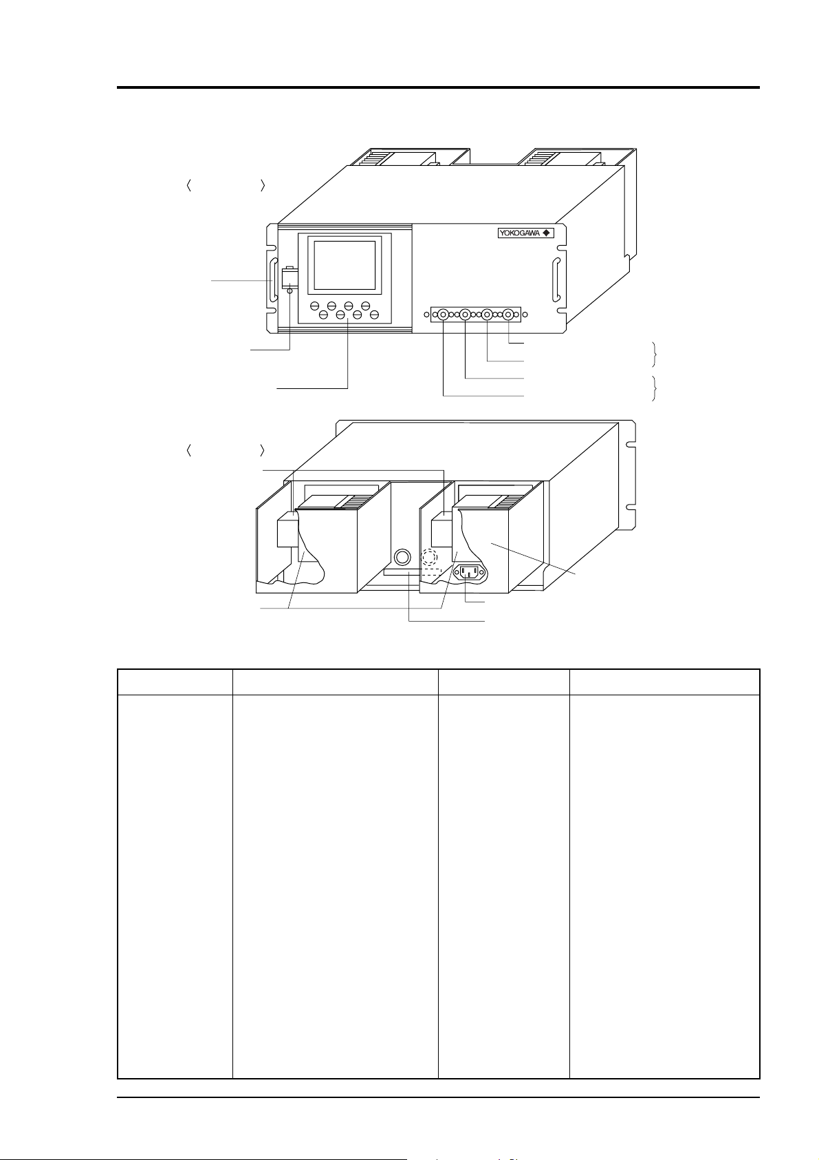
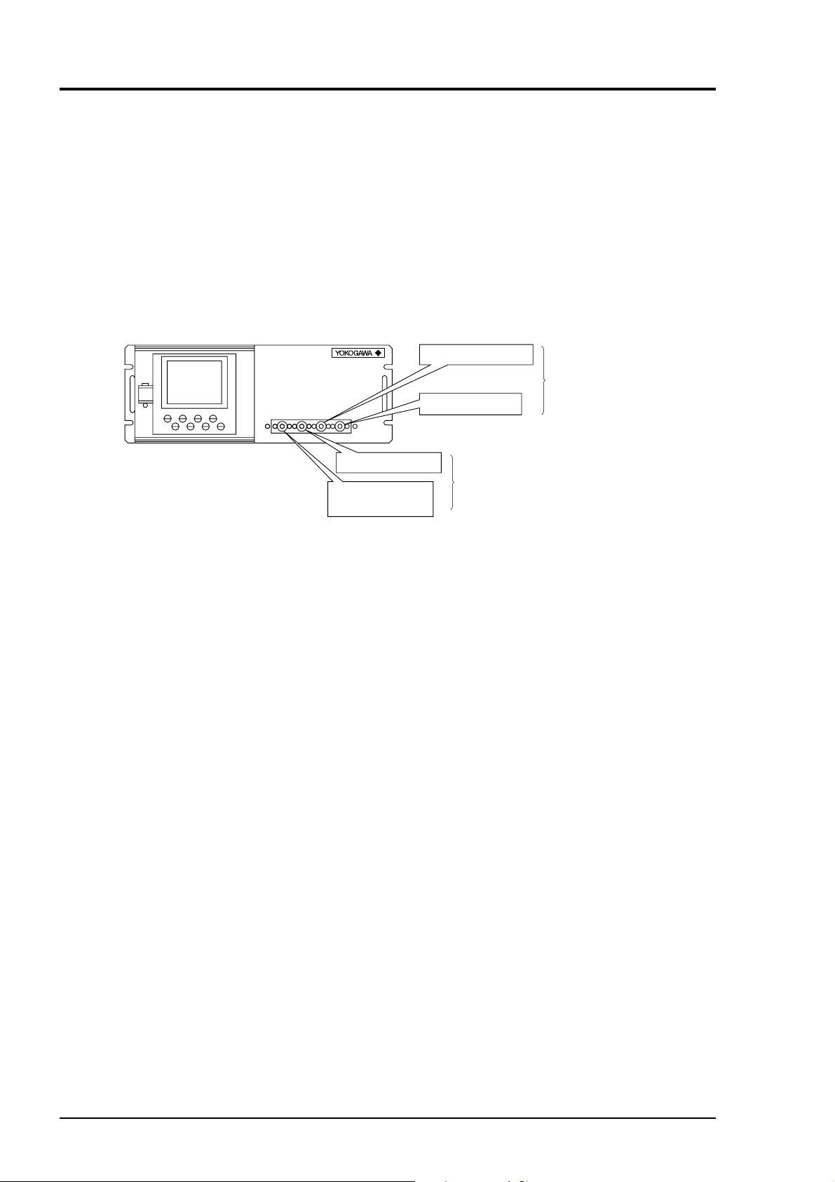
2. NAME AND DESCRIPTION OF EACH UNIT
2.1 Name and description of main unit
Front panel
POWER
(1) Handle
(2) Power switch
(3) Display/operation panel
Back panel
(6) Sector motor
(7) Light source cover
Name
(1) Handle
Used for withdrawing the main
unit from the panel.
Description
Fig. 2-1
(6) Sector motor
(4) Sampling gas inlet
(5) Sampling gas outlet
(4) Sampling gas inlet
(5) Sampling gas outlet
(or purge gas inlet)
(10) Protective cover
(9) Power inlet
(8) Input/output terminal connector
Name
For measuring
unit 1
For measuring
unit 2
Description
For driving the rotation of
sector
(2) Power switch
(3) Display/opera tion
(4) Sampling gas
inlet
(5) Sampling gas
outlet
IM 11G02N01-01E
Used for ON/OFF the analyzer.
Liquid crysral diaplay and keys
for setting various functions
For connecting to the measuring
gas tube
Connect to the exhaust line. (A
pair of sampling gas inlet/outlet is
provided for each measuring unit.
When ordered with purge, the
piping to measuring unit 2 is built
inside. In this case, the sample gas
outlet for measuring unit 2 is used
for purge gas inlet.)
(7) Light source
cover
(8) Input/output ter minal connector
(9) Power inlet
(10) Protective cover
Infrared light source is
arranged in the cover.
For connecting to the external
input/output terminal module
For connecting the power cable
Protective cover for the light
source and the motor. May be
removed during operation.
2 - 1
Page 13
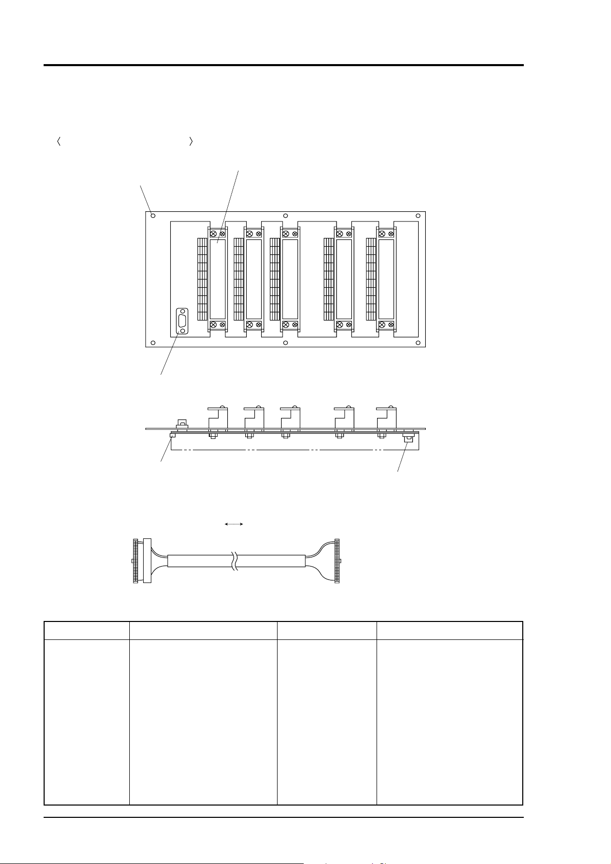
2.2 Input/Output terminal module
This analyzer provides input/output of various signals from the supplied input/outpt terminal
module by connecting the instrument to this module.
Input/Output terminal module
(2) Input/Output terminal block (TN1 to TN5)
(1) Mounting hole (φ4.5, 6 places)
TN1 TN2 TN3 TN4 TN5
(6) Communication connector (CN2)
Name
(1) Mounting
hole
(2) Input/output
terminal
block
(TN 1 to TN
5)
(3) Cable
connection
connector
(3) Cable connection connector (CN1)
(4) Analyzer main unit
Input/Output terminal module connection cable (1m)
Fig. 2-2
Description
Used for mounting input/output
terminal module.
φ φ
φ 4.5, 6 places
φ φ
Input/output terminal for
signals of analog output, range
identification contact, alarm
contact output, etc.
Used for connecting the analyzer
main unit and the input/output
terminal module (4).
(5) Calibration solenoid valve drive signal
output connector (CN3)
Name
(4) Input/output
terminal module
connection cable
(5) Calibration
solenoid valve
drive signal
output connector
(6) Communication
connector
Description
Used for connecting the
analyzer main unit to the input/
output terminal module.
Cable connector for connecting
the analyzer to the relay board
for automatic calibration.
Connect communication cable.
*Please refer to another manual
(IM 11G02P01-01E) about
communication function.
2 - 2
IM 11G02N01-01E
Page 14

3. INSTALLATION
DANGER
This unit is not explosion-proof type. Do not use it in a place with explosive gases to prevent
explosion, fire or other serious accidents.
CAUTION
•Entrust the installation, movement or re-installation to a specialist or the supplier. A poor
installation may cause accidental tipover, shock hazard, fire, injury, etc.
•The gas analyzer is heavy. It should be installed with utmost care. Otherwise, it may tip
over or drop, for example, causing accident or injury.
•For lifting the gas analyzer, be sure to wear protective gloves. Bare hands may invite an
injury.
•This unit should be installed in a place which conforms to the conditions noted in the
instruction manual. Otherwise, it may cause electric shocks, fire or malfunction of the unit.
•During installation work, care should be taken to keep the unit free from entry of cable chips
or other foreign objects. Otherwise, it may cause fire, trouble or malfunction of the unit.
3.1 Installation conditions
To install the analyzer for optimum performance, select a location that meets the following
conditions;
(1) This instrument is system built in type. This instrument should be used while embedded
in a panel, locker, or enclosure of steel sheet.
(2) Use this instrument indoors.
(3) A vibration-free place
(4) A place which is clean around the analyzer.
(5) Power supply
Rated voltage : 100 V to 240 V AC
Operating voltage : 85 V to 264 V AC
Rated frequency : 50/60 Hz
Power consumption : 250 VA max.
Inlet : Comformity to EN60320 class I type 3-pin inlet
(6) Operation conditions
Ambient temperature : -5˚ to 45˚
Ambient humidity : 90% RH or less, no condensation
C
IM 11G02N01-01E
3 - 1
Page 15
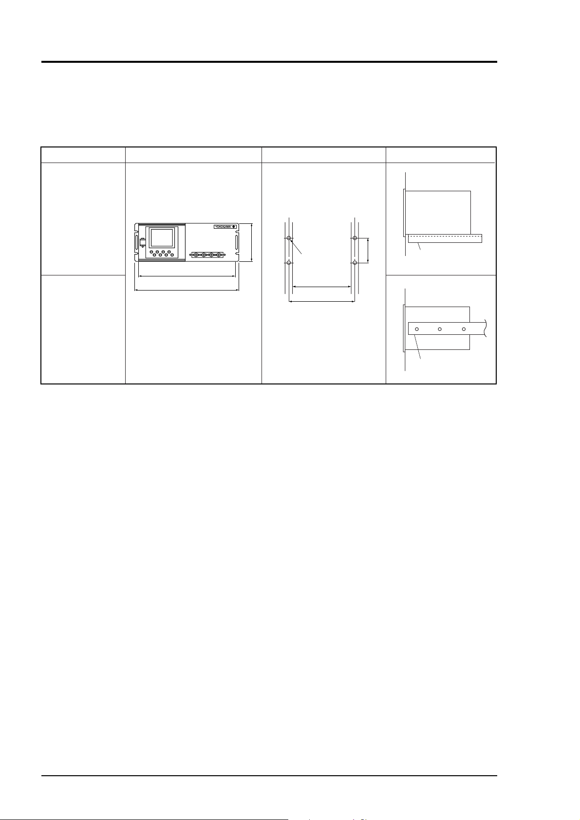
3.2 Installation
3.2.1 Installation of analyzer main frame
Installation methods for the analyzer main unit are divided into 2 types;
(
Unit : mm
Type External dimensions Mounting dimensions Mounting method
19 inch rack
mounting guide
rail method
19 inch rack
mounting slide
429
483
177
M6
450 or more
465
101.6
Slide rail
(Supports mass)
rail method
Slide rail
(Supports mass)
Note 1 Check and maintenance of the analyzer main unit may be carried out with the top cover detached.
The guide rail method may be used if a space accessible for maintenance is provided at the top of
the main unit. If maintenance space is not provided specially, it is recommended to use the slide
rail method.
Recommended slide rail: Product No.: 305A-24 manufactured by Accuride International Co.
Note 2 For 19 inch rack mounting, the weight of the analyzer is supported with the bottom of the case
(with the side of the case in case of slide rail method). For mounting dimensions of the slide rail,
see “Item 9.3 External diagram”.
Don’t install the analyzer at a place which is exposed to direct sunlight.
The analyzer should be installed at a place where ambient temperature is within -5 to 45˚C, and
temperature fluctuation during use is minimum.
)
3 - 2
IM 11G02N01-01E
Page 16
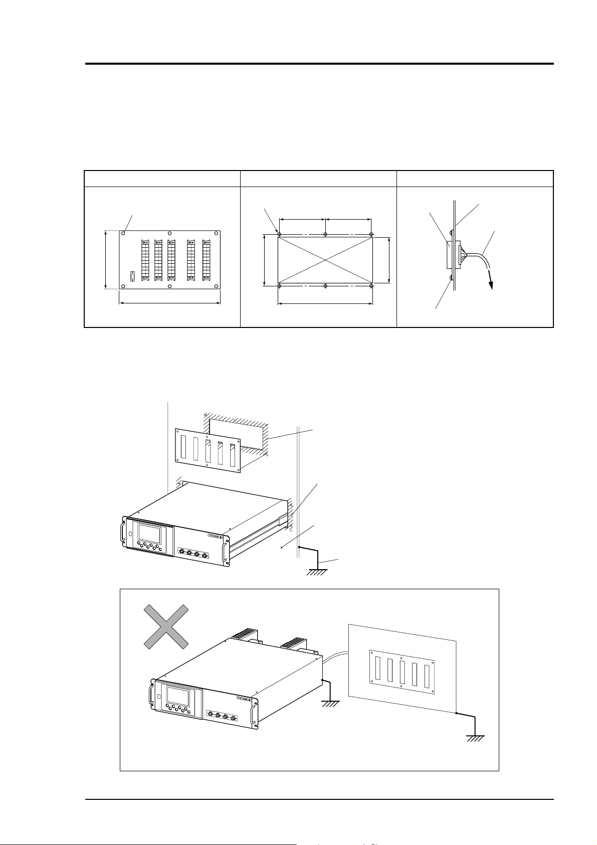
3.2.2 Mounting input/output terminal module
Mount the input/output terminal module on the panel; observing the following method.
(Note) To avoid the effect of noise generated from external units, mount the I/O terminal module
mounting plate on the panel for continuity at the mounting surface and connect the panel
to the same ground as the analyzer main unit.
External dimensions Mounting dimensions Mounting method
4.5 mounting hole (× 6 places)
164
316
M4 screw (× 6 places)
150 150
154
Rectangular hole
302
Note) How to ground analyzer main unit and I/O terminal module
To avoid the effect of noises, etc. from external units, it is
recommended to ground them by the procedure described below.
Bring I/O terminal module sheet metal and
panel into continuity at ///// portion.
Bring analyzer main unit and panel into continuity
at ///// portion or rail mounting portion.
(No grounding is required at the power terminal).
Terminal
142142
Screwed to panel
Panel plate
Connection cable
To analyzer rear panel
IM 11G02N01-01E
Mount the analyzer and I/O terminal module on the
same panel.
Ground the panel casing.
Don’t separate the analyzer and I/O terminal module, and be sure to
*
ground them together.
3 - 3
Page 17
3.3 Piping
Piping should be connected to the gas inlets and outlets of the front panel of the analyzer.
• Use a corrosion resistant tube of Teflon, stainless or polyethylene to connect the instrument to
a sampling system. Even if there is a danger of corrosion, refrain from using a tube of rubber
or soft vinyl. The instrument provides inaccurate indication due to gas absorption by piping
materials.
• Pipe connection port is Rc1/4 female thread (or 1/4 NPT). Piping should be cut as short as
possible for a quick response. About 4 mm inner diameter is recommended.
• Entry of dust into the instrument may result in defective operation. Use a clean piping or
coupling.
Connect the gas tube by the following method.
Sampling gas outlet
For measuring
unit 1
Sampling gas inlet
Sampling gas inlet
Sampling gas outlet
(Purge gas inlet)
For measuring
unit 2
Sampling gas inlet: Attach the gas tube to introduce gas to be measured such as one that has
completed dehumidification process and standard gases for zero and span
calibration to this inlet.
Gas flow to be introduced should be constant within the range of 0.5 ± 0.2
L/min.
Sampling gas outlet: Exhaust measured gas through the outlet. Attach the tube to exhaust mea-
sured gas outdoors or to the atmosphere.
Purge gas inlet: It is used for purging the inside of the total gas analyzer . When the ana-
lyzer must be purged, refer to Item 3.3.4 Purging of instrument inside.
Use dry gas N
or instrumentation air for purge gas. (flow rate of 1L/min or
2
more should be used and no dust or mist is contained).
3 - 4
IM 11G02N01-01E
Page 18
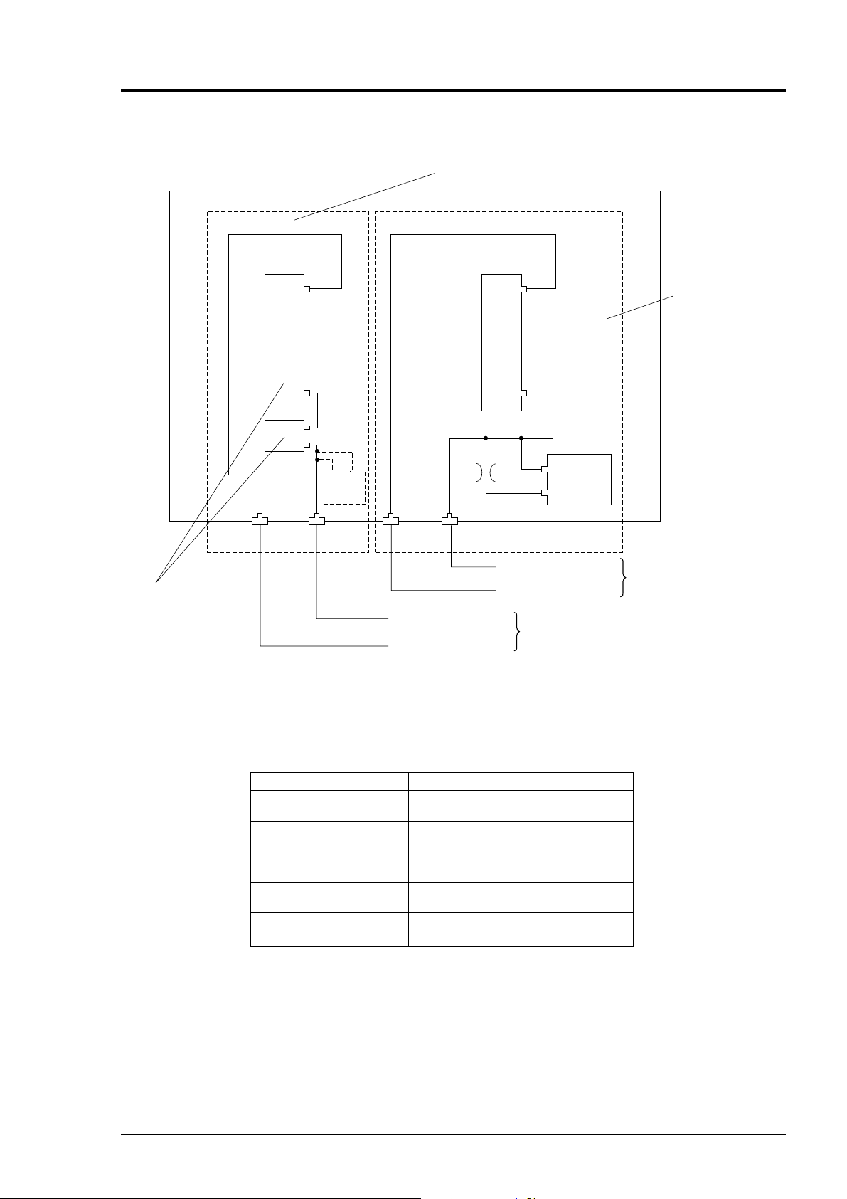
Internal piping diagram
Measuring unit 2
Measuring unit 1
Built-in
sensor
O
2
Built-in
O
sensor
2
OUTLET INLET OUTLET INLET
Sampling cell
Note)
2 cells may be used
by combination of
Sampling gas inlet
Sampling gas outlet
Sampling gas inlet
Sampling gas outlet
For measuring
unit 2
For measuring
unit 1
range.
Note) When the purge gas inlet is provided, the piping to measuring unit 2 is built inside.
Correspondence of measured components and measuring units
Measuring components
1-component Analyzer for
NO, SO
, CO2, CO and CH
2
2-component Analyzer for
NO-SO
and CO2-CO
2
2-component Analyzer for
NO-CO
3-component Analyzer for
NO-SO2-CO
4-component Analyzer for
NO-SO
-CO2-CO
2
Measuring unit 1
Each component
4
NO-SO
CO2-CO
NO
NO-SO
NO-SO
2
2
2
Note) When there are two measuring units, the built-in O2 sensor must
be connected to the measuring unit 2.
Measuring unit 2
None
None
CO
CO
CO
-CO
2
IM 11G02N01-01E
3 - 5
Page 19
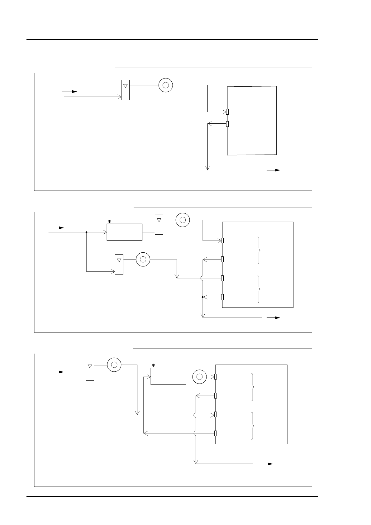
Example of connecting each measuring unit
?
One pair of gas inlet/outlet
Sampling gas
Flow meter
0.5L/min
?
Two pair of gas inlet/outlet - (1)
Sampling gas
NO2/NO
converter
Flow meter
0.5L/min
Filter
Filter
Flow meter
0.5L/min
Filter
IR400
Sampling gas inlet
Sampling gas outlet
Release to atmosphere.
IR400
Sampling gas
inlet
Sampling gas
outlet
Sampling gas
inlet
Sampling gas
outlet
Exhaust
For
measuring
unit 1
For
measuring
unit 2
Note) The NO
when NO measurement is used for NOx measurement.
?
Two pair of gas inlet/outlet - (2)
Sampling gas
Note) The NO
when NO measurement is used for NOx measurement.
/NO converter is used
2
Filter
Flow meter
0.5L/min
/NO converter is used
2
/NO
NO
2
converter
Filter
Sampling gas
inlet
Sampling gas
outlet
Sampling gas
inlet
Sampling gas
outlet
Exhaust
Release to atmosphere.
IR400
For
measuring
unit 1
For
measuring
unit 2
Exhaust
Release to atmosphere.
3 - 6
IM 11G02N01-01E
Page 20
3.4 Sampling
3.4.1 Conditions of sampling gas
1. Dust contained in the sampling gas should be completely removed with a filter. For the final
stage filter, use a filter that allows removing dust particles of 0.3mm.
2. Dew point of sampling gas must be lower than the ambient temperature to avoid occurrence
of drain in the gas analyzer. If vapor is contained in the sampling gas, dew point should be
lowered to 0°C by using a dehumidifier.
3. If SO
4. Corrosive gases such as Cl
5. Temperature of sampling gas should be within 0 to 50°C. Provide a means that prevents
3.4.2 Sampling gas flow
Flow of sampling gas should be 0.5 ± 0.2L/min.
Avoid flow fluctuation during measurement.
Observe the flow reading by a flowmeter provided as shown in the example of the sampling
system configuration (Item 3.4.6).
3.4.3 Preparation of standard gas
mist is contained in the sampling gas, use a mist filter or cooler to remove SO3 mist.
3
Other mists should be removed by using a mist filter or cooler.
2
erable amounts, will shorten the life of instruments.
entry of hot gas directly into the instrument.
, F2 and HCl, if they are contained in the sampling gas in consid-
Routine calibration is required by standard gas for keeping this instrument under normal operation
condition (once a week). Prepare a standard gas cylinder for zero calibration and span calibration.
Zero gas
Span gas other
than for O
measurement
Span gas for O
measurement
2
Analyzer without O
measurement
N2 gas
Gas with concentration of 90% or more
of full scale
2
Analyzer with built-in O
2
sensor
N2 gas
Gas with concentration of
90% or more of full scale
Gas with concentration of
90% or more of full scale or
atmospheric air (21%)
3.4.4 Reduction of moisture interference
NO and SO
2 measurement is subject to moisture interference.
As shown by the configuration example on the next page, provide a device for humidifying zero
calibration gas, thus controlling the moisture content at a constant level (moisture content in
sample gas should also be controlled here) in configuring a sampling system. That allows the
same moisture content as in the case of measurement to be contained in zero gas for calibration.
3.4.5 Purging of instrument inside
Analyzer with external zirconia O
2
sensor
Dry air or atmospheric air (Note)
Gas with concentration of 90% or
more of full scale
1 to 2% O
2
2
The inside of instrument need not be purged generally except for the following cases.
1. A combustible gas component is contained in sample gas.
2. Corrosive gas is contained in the atmospheric air at the installation site.
3. The same gas as the sample gas component is contained in the atmospheric air at the installa-
tion site.
In such cases as above, the inside of analyzer should be purged with the air for instrumentation
or N2. Purging flow rate should be about 1L/min.
If dust or mist is contained in purging gas, it should be eliminated completely in advance.
IM 11G02N01-01E
3 - 7
Page 21
3.4.6 Pressure at sampling gas outlet
Pressure at the sampling gas outlet should be adjusted to atmospheric pressure.
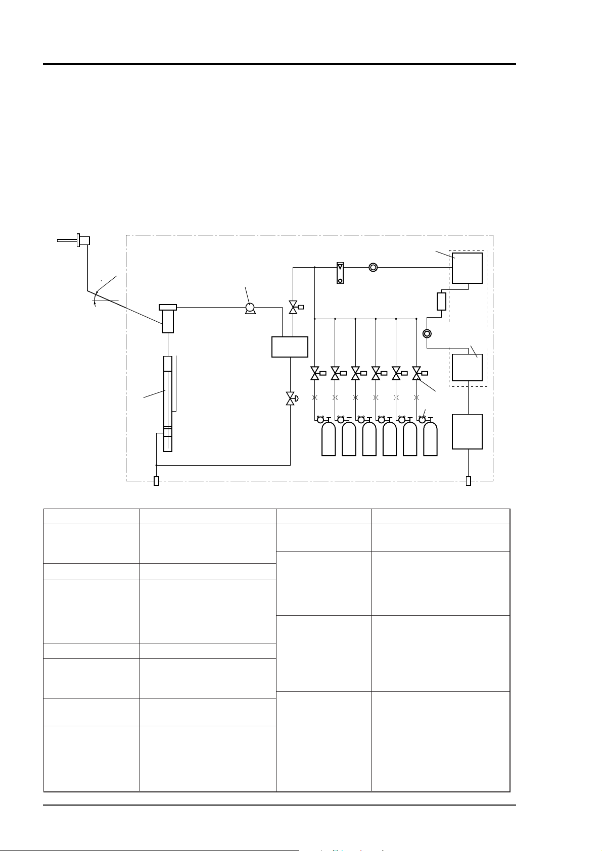
3.4.7 Example configuration of gas sampling system
The following illustrates a typical system configuration for five component gas measurement for
monitoring combustion exhaust gas from boiler, refuse incinerator, etc.
Contact Yokogawa for system configuration matching the particular use or further information.
(1) Gas extractor
φ10/φ8
Teflon
tube
15
or larger
(2) Mist filter
(4) Gas aspirator
2-way
solenoid
valve
(5)
Electronic
gas cooler
(8) Flowmeter
Infrared gas analyzer
main unit CO,CO
(7) Membrane filter
(O2)
2
(11)
NO
converter
(7)
Membrane filter
Infrared gas analyzer
main unit NO, SO
IR400
/NO
2
2
Name
(1) Gas extractor
(2)
Mist filter
(3) Safety drain trap
(4) Gas aspirator
(5) Electronic gas
cooler
(6)
Solenoid valve
(7) Membrane filter
(3) Safety
drain
trap
Drain
Description
Gas extractor with a heating
type stainless steel filter of standard mesh 40 m
Removes drain, mist, and dust.
The safety drain trap divided
into two rooms for positive and
negative pressure. It monitors
and adjusts the sample gas pressure.
For aspiration of sample gas
Dries the moisture in sample
gas to a dew point of approx.
2˚C.
Used for introducing calibration gas.
PTFE filter used to eliminate
fine dust particles and permit
monitoring of dust adhering
condition on the front panel of
the gas analyzer.
ZERO NO SO
Air
Name
(8) Flowmeter
(9) Standard gas
(10)Zirconia O
2
sensor
(11)NO2/NO con-
verter
NO
/N
2
Pressure
reducing valve
O
2
/N
2
(6)
Solenoid
valve
2
CO O
CO
2
2
SO
CO
2
/N
2
(9) Standard gas
CO
/N
2
/N
2
2
Description
Adjusts and monitors the flow
rate of sample gas.
Reference gas used for calibrating zero and span of the analyzer. Total 6 cylinders required
for zero gas air, span gas NO,
, CO, CO2 and O2.
SO
2
External zirconia oxygen
sensor used for measuring the
oxygen concentration in
sample gas.
(This is not necessary in case
when O
sensor is built-in.)
2
Added to NOx analyzer.
A special catalyst material for
efficient conversion of NO
gas to NO is used.
(10)
Zirconia
O
senor
2
(ZX8D)
Exhaust
2
3 - 8
IM 11G02N01-01E
Page 22
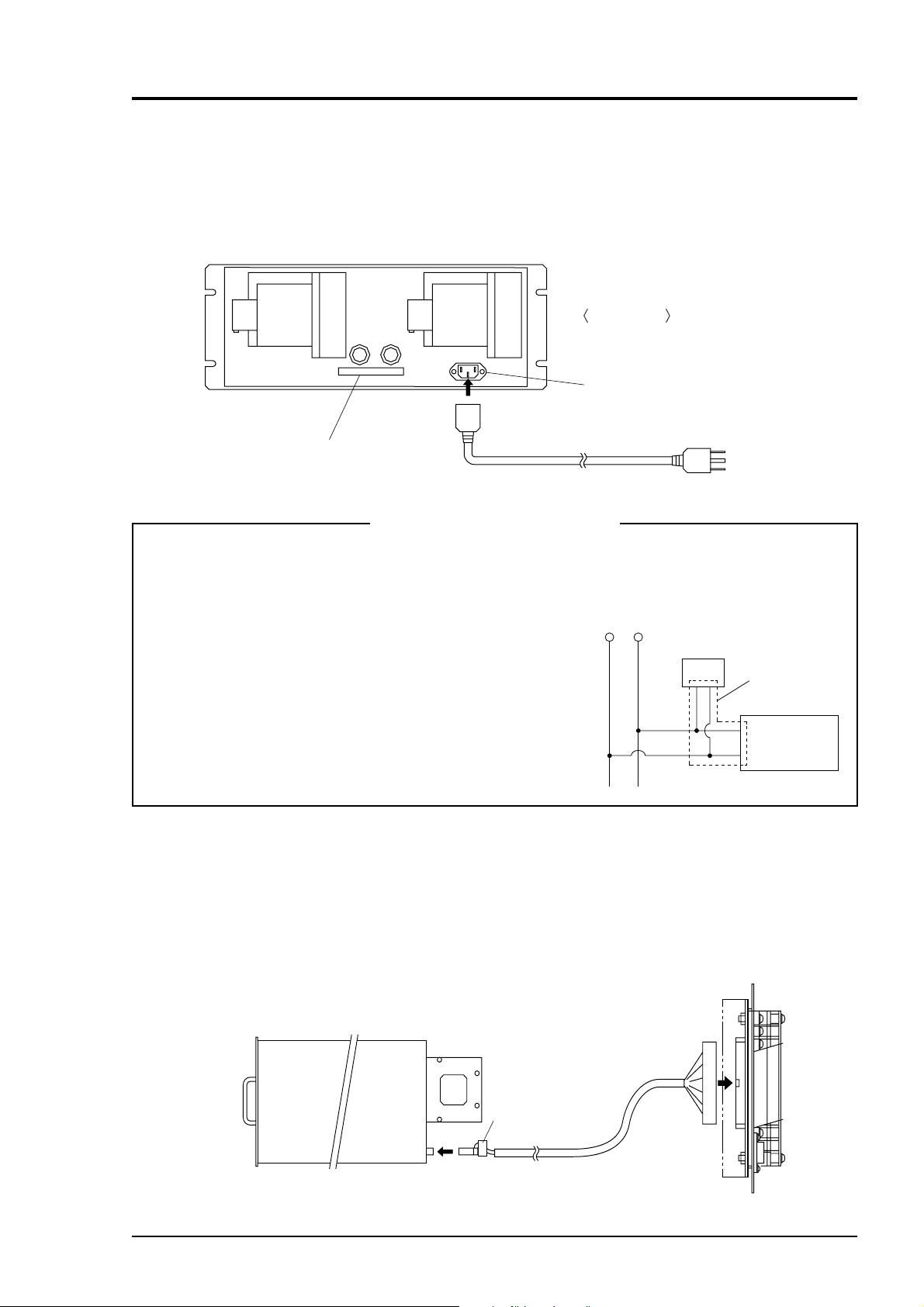
3.5 Wiring
3.5.1 Power inlet
The power inlet is provided at the rear panel.
Connect supplied power cable to this power inlet.
Rear panel
Power inlet
Input/output terminal connector
Grounding 2-pole plug
When noise source is in the vicinity
• Avoid installing this instrument near an electrical unit (high frequency furnace or electric welder)
that generates much electrical noise. If using the
instrument near such a noise generating unit is
unavoidable, use a different power line to avoid noise.
Main unit
power supply
Varistor or
spark killer
• Mount a noise suppressor such as varister or spark killer
as shown at right figure to the noise generating unit when
noise is generated from relays or solenoid valves.
Mount the suppressor near the noise generating source,
or it will have no effect.
3.5.2 Input/output terminal module
This analyzer should be connected to the input/output terminal module by supplied exclusive
cable.
Plug this cable connector into the receptacle at the rear panel of the analyzer and the receptacle on
the PC board of the input/output module.
Connect the exclusive cable so that the ferrite core attached to the cable comes to the analyzer
side.
Ferrite core
(to analyzer side)
Install (connect)
near the source.
Noise
generating
source
IM 11G02N01-01E
Analyzer
Exclusive cable
(1 meter long)
Input/output
terminal module
3 - 9
Page 23

(1) Analog output signal (AO): terminal block 1, 1 to 20, terminal block 2, 3 to 6.
Output signal: 4 to 20 mA DC or 0 to 1 V DC (selected when ordering)
Non-insulated output
Allowable load: 4 to 20 mA DC, 550Ω or less
0 to 1 V DC, 100kΩ or more
• Analog output is provided from each terminal corresponding to the channel displayed in the
measurement screen.
All of analog output signals for the instrument are not isolated. It is recommended to isolate
signals individually to prevent interference from unnecessary signals or to prevent external
interference, especially leading the cable of more than 30 meters or to outdoor.
(2) O
sensor input: terminal block 2, 1 to 2.
2
Input signal:
External zirconia O
External O
analyzer: 0 to 1 V DC (DC input resistor of 1MΩ or more)
2
• It is used when the external zirconia O
• To connect to the output of the external Zirconia analyzer or external O
analyzer: Zirconia O2 sensor signal (ZX8Dp C output)
2
analyzer or external O2 analyzer is specified as order.
2
analyzer prepared
2
separately.
• In case of an external O
analyzer, input a signal of 0 to 1 V DC with respect to O2 full scale
2
of the analyzer.
• In case of built-in O
O
sensor input is not isolated. It is recommended to isolate when an external O2 analyzer is
2
installed apart from this analyzer. Zirconia O
analyzer, do not use the terminals.
2
sensor Yokogawa make IR400 should be
2
installed at a location that is as close to this instrument as possible.
(3) Contact input (DI): terminal block 2, 1 to 20, terminal block 3, 5 to 10.
• It is for a contact input at no voltage. An input is provided when switching to short circuit
(on) or open (off).
• No voltage is applied to the terminals.
(4) Contact output (DO): terminal block 3, 11 to 20, terminal block 4 and terminal block 5
• Contact rating: 250 V AC/2 A, load resistance
• An output is for a relay contact output. An output is provided when switching to conductive
(on) or open (off).
3 - 10
Wiring of analog output signal, O
sensor input and contact input should be fixed separately
2
from the wiring of power supply and contact output.
Note) To avoid the effect of noise generated from external units, be sure to ground the
analyzer main unit. Continue between the I/O module mounting plate and the panel
and connect the panel casing to the same ground as the analyzer.
IM 11G02N01-01E
Page 24
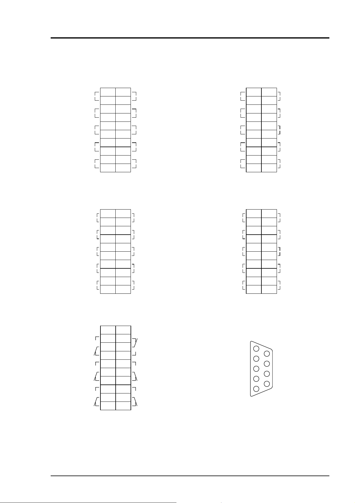
(5) List of terminal blocks
Ch5 output
(Ch5_OUT)
Ch4 output
(Ch4_OUT)
Ch3 output
(Ch3_OUT)
Ch2 output
(Ch2_OUT)
Ch1 output
(Ch1_OUT)
Unassigned
Unassigned
Remote hold input
(R_HOLD)
Average value reset
input (RESET)
Auto calibration
remote start
input (R_CAL)
Terminal block 1
<TN1>
11
1
—
+
—
+
—
+
—
+
—
+
12
2
13
3
14
4
15
5
16
6
17
7
18
8
19
9
20
10
(M3.5 screw)
—
+
—
+
—
+
Terminal block 3
<TN3>
11
1
12
2
13
3
14
4
15
5
16
6
17
7
18
8
19
9
20
10
(M3.5 screw)
Ch10 output
(Ch10_OUT)
Ch9 output
(Ch9_OUT)
Ch8 output
(Ch8_OUT)
Ch7 output
(Ch7_OUT)
Ch6 output
(Ch6_OUT)
Ch5 range identification
contact output (RNG_ID Ch5)
Ch4 range identification
contact output (RNG_ID Ch4)
Ch3 range identification
contact output (RNG_ID Ch3)
Ch2 range identification
contact output (RNG_ID Ch2)
Ch1 range identification
contact output (RNG_ID Ch1)
Note 1
sensor input
O
2
(O
_IN)
2
Ch12 output
(Ch12_OUT)
Ch11 output
(Ch11_OUT)
Unassigned
Unassigned
Note 1 : For external O
Peak count alarm
output (PEAK_ALM)
Auto calibration
status/
contact
output (CAL)
Pump ON/OFF
contact output (PUMP)
Calibration error
contact output
(CAL_ALM)
Instrument error
contact output
(FAULT)
Terminal block 2
<TN2>
+
12
2
13
3
14
4
15
5
16
6
17
7
18
8
19
9
20
10
(M3.5 screw)
sensor input.
2
11
1
—
Terminal block 4
<TN4>
11
1
12
2
13
3
14
4
15
5
16
6
17
7
18
8
19
9
20
10
(M3.5 screw)
Ch5 remote range
switch input
(R_RNG_Ch5)
Ch4 remote range
switch input
(R_RNG_Ch4)
Ch3 remote range
switch input
(R_RNG_Ch3)
Ch2 remote range
switch input
(R_RNG_Ch2)
Ch1 remote range
switch input
(R_RNG_Ch1)
Unassigned
Unassigned
Unassigned
Unassigned
Unassigned
Unassigned
Alarm 3 output
(ALM_3)
Alarm 2 output
(ALM_2)
Alarm 1 output
(ALM_1)
IM 11G02N01-01E
Terminal block 5
<TN5>
11
1
12
2
13
3
14
4
15
5
16
6
17
7
18
8
19
9
20
10
(M3.5 screw)
Unassigned
Alarm 6
output
(ALM_6)
Alarm 5
output
(ALM_5)
Alarm 4
output
(ALM_4)
Connector
<CN3>
Solenoid valve drive signal output for calibration
Contact output for
sample gas selection
Contact output for
zero calibration
Contact output for Ch1
span calibration
Contact output for Ch2
span calibration
(Transister output)
1
2
3
4
5
<D-sub 9P>
Contact output for Ch3
6
span calibration
Contact output for Ch4
7
span calibration
Contact output for Ch5
8
span calibration
9
Power for relay drive
5V DC
3 - 11
Page 25
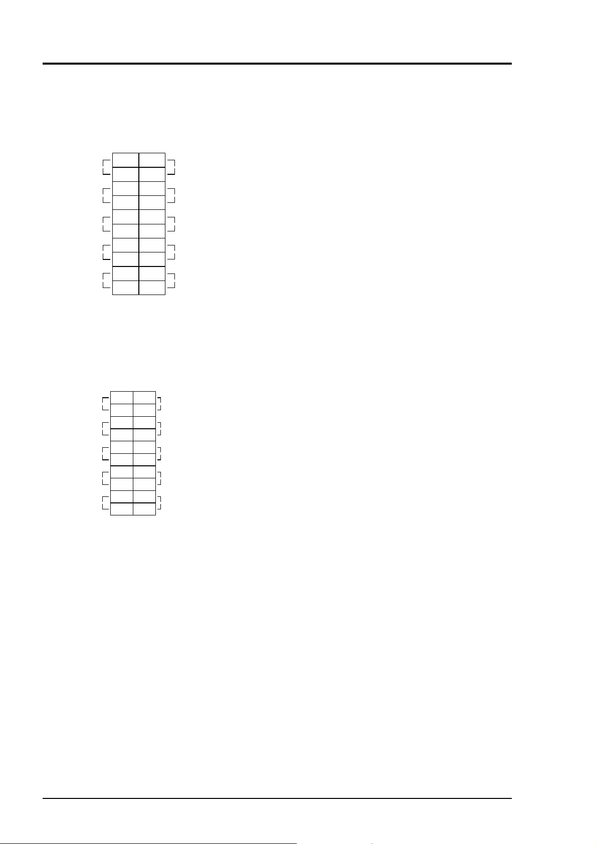
(6) Description on terminal block
Terminal block 1
<TN1>
11
Ch5 output
(Ch5_OUT)
Ch4 output
(Ch4_OUT)
Ch3 output
(Ch3_OUT)
Ch2 output
(Ch2_OUT)
Ch1 output
(Ch1_OUT)
1
—
+
2
3
—
+
4
5
—
+
6
7
—
+
8
9
—
+
10
(M3.5 screw)
12
13
14
15
16
17
18
19
20
Terminal block 2
O
Note 1
sensor input
2
(O
_IN)
2
Ch12 output
(Ch12_OUT)
Ch11 output
(Ch11_OUT)
Unassigned
Unassigned
Note 1: For external O2 sensor input.
<TN2>
1
—
+
2
3
—
+
4
5
—
+
6
7
8
9
10
(M3.5 screw)
11
12
13
14
15
16
17
18
19
20
Ch10 output
—
+
(Ch10_OUT)
Ch9 output
—
+
(Ch9_OUT)
Ch8 output
—
+
(Ch8_OUT)
Ch7 output
—
+
(Ch7_OUT)
Ch6 output
—
+
(Ch6_OUT)
Ch5 remote range
changeover input
(R_RNG_Ch5)
Ch4 remote range
changeover input
(R_RNG_Ch4)
Ch3 remote range
changeover input
(R_RNG_Ch3)
Ch2 remote range
changeover input
(R_RNG_Ch2)
Ch1 remote range
changeover input
(R_RNG_Ch1)
Terminal block 1 <TN1>
Terminal block for analog output (non-isolated output)
Between 1–2: Ch5 output
Between 3–4: Ch4 output
Between 5–6: Ch3output
Between 7–8: Ch2 output
Between 9–10: Ch1 output
Between 11–12: Ch10 output
Between 13–14: Ch9 output
Between 15–16: Ch8 output
Between 17–18: Ch7 output
Between 19–20: Ch6 output
Terminal block 2 <TN2>
Between 1–2: O
sensor input
2
(For input of Fuji’s zirconia
oxygen sensor or externally
oxygen sensor. Must not be used
unless external O
sensor is
2
provided.)
Between 3–4: Ch12 output
Between 5–6: Ch11 output
Between 7–10 For internal connection. Must not
be wired. (Must not be used as
junction terminal).
Between 11–12: Ch5 remote range switch input
Between 13–14: Ch4 remote range switch input
Between 15–16: Ch3 remote range switch input
Between 17–18: Ch2 remote range switch input
Between 19–20: Ch1 remote range switch input
3 - 12
Action of remote range switch
High range is selected when open.
Low range is selected when short-
circuited. For details of action, see
“Item 6.1 Switch of range.”
IM 11G02N01-01E
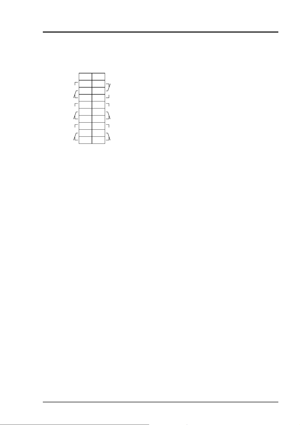
Page 26

Unassigned
Unassigned
Remote hold input
(R_HOLD)
Average value reset
input (RESET)
Auto calibration
remote start
input (R_CAL)
Terminal block 3
<TN3>
11
1
12
2
13
3
14
4
15
5
16
6
17
7
18
8
19
9
20
10
(M3.5 screw)
Ch5 range identification
contact output (RNG_IDCh5)
Ch4 range identification
contact output (RNG_IDCh4)
Ch3 range identification
contact output (RNG_IDCh3)
Ch2 range identification
contact output (RNG_IDCh2)
Ch1 range identification
contact output (RNG_IDCh1)
Terminal block 3 <TN3>
Between 1–4: For internal connection. Must
not be wired. (Must not be used
as junction terminal.)
Between 5–6: Remote hold input. No hold
when open. Output hold when
short-circuited.
For details, refer to “Item 6.7
Parameter setting, Output Hold”.
Between 7–8: Average value reset input. short-
circuitting the contact input (for
at 1.5 sec min.) resets O
and O
corrected average simulta-
2
average
2
neously. Opening it restarts the
average value.
For details, refer to “Item 6.7
Parameter setting, Average Value
Resetting”
Between 9–10: Automatic calibration remote
start input
After shorting for 1.5 sec. or
more, automatic calibration is
started by the opening input
whether the automatic calibration
setting is ON/OFF.
For details, refer to “Item 6.4
Setting of auto calibration”
Between 11–12: Ch5 range identification contact
output
Between 13–14: Ch4 range identification contact
output
Between 15–16 Ch3 range identification contact
output
Between 17–18: Ch2 range identification contact
output
Between 19–20: Ch1 range identification contact
output
IM 11G02N01-01E
Action of range identification signal
Range identification contact is
conductive at low range and open
at high range.
3 - 13
Page 27

Peak count alarm
output (PEAK_ALM)
Auto calibration status/contact
contact output (PUMP)
output (CAL)
Pump ON/OFF
Calibration error
contact output
(CAL_ALM)
Instrument error
contact output
(FAULT)
Terminal block 4
<TN4>
11
1
12
2
13
3
14
4
15
5
16
6
17
7
18
8
19
9
20
10
(M3.5 screw)
Unassigned
Unassigned
Unassigned
Unassigned
Unassigned
Terminal 4 <TN4>
Between 1–2: Peak count alarm contact output
It is conductive when peak count
exceeds the setting time. It
remains open below the setting
time. For setting and operation,
refer to “Item 6.6 Peak alarm
setting”.
Between 3–4: Contact output of auto calibration
status
When the auto calibration is
carried out and remote hold is
ON, it is conductive. Remains
open otherwise.
Between 5–6: Pump ON/OFF contact output
Used when turning ON/OFF the
pump. It is open during auto and
manual calibration status and
conductive during measurement.
Between 7–8: Calibration error contact output
It is conductive when an error
occurs during zero calibration or
span calibration. It is normally
open.
Between 9–10: It is conductive when an error
occurs to the analyzer unit. It is
normally open.
Between 11–20: For internal connection, wiring is
not allowed. (Do not use it as
junction terminal).
3 - 14
IM 11G02N01-01E
Page 28
Unassigned
Ch3 alarm output
(ALM_Ch3)
Ch2 alarm output
(ALM_Ch2)
Ch1 alarm output
(ALM_Ch1)
Terminal block 5
<TN5>
11
1
12
2
13
3
14
4
15
5
16
6
17
7
18
8
19
9
20
10
(M3.5 screw)
Unassigned
Power disconnection
alarm output
(POWER_OFF)
Ch5 alarm output
(ALM_Ch5)
Ch4 alarm output
(ALM_Ch4)
Terminal 5 <TN5>
Between 2, 3 and 4:
Ch3 alarm output
When the output exceeds the set value,
it is conductive between 2 and 3, and
open between 3 and 4. Otherwise, it is
open between 2 and 3 and conductive
between 3 and 4.
Between 5, 6 and 7:
Ch2 alarm output
When the output exceeds the set value,
it is conductive between 5 and 6, and
open between 6 and 7. Otherwise, it is
open between 5 and 6, and conductive
between 6 and 7.
Between 8, 9 and 10:
Ch1 alarm output
When the output exceeds the set value,
it is conductive between 8 and 9, and
open between 9 and 10. Otherwise, it
is open between 8 and 9.
Between 12, 13 and14:
Analyzer unit power OFF output
When the analyzer unit is turned ON,
it is conductive between 12 and 13,
and open between 13 and 14. When
the analyzer unit is turned OFF, it is
open between 12 and 13, and conductive between 13 and 14.
Between 15, 16 and 17:
Ch5 alarm output
When the output exceeds the set value,
it is conductive between 15 and 16,
and open between 16 and 17. Otherwise, it is open between 15 and 16,
and conductive between 16 and 17.
Between 18, 19 and 20:
Ch4 alarm output
When the output exceeds the set value,
it is conductive between 18 and 19,
and open between 19 and 20. Otherwise, it is open between 18 and 19,
and conductive between 19 and 20.
For detailed action of the alarm
contact, refer to “Item 6.3 Alarm
setting”.
IM 11G02N01-01E
3 - 15
Page 29
Connector <CN3>
Solenoid valve drive signal output for calibration
Connector
<CN3>
(Transister output)
Contact output for
sample gas selection
Contact output for
zero calibration
Contact output for Ch1
span calibration
Contact output for Ch2
span calibration
1
2
3
4
5
<D-sub 9P>
Contact output for Ch3
6
span calibration
Contact output for Ch4
7
span calibration
Contact output for Ch5
8
span calibration
Power for relay drive
9
5V DC
Connector <CN3> provides outputs in combination with calibration action during auto calibration
and manual calibration.
An output is from a transistor (ratings: 5 V/50 mA).
A transistor is turned ON before starting each calibration.
Sample selection output is ON during measurement and OFF during calibration.
If calibration is not performed, the other transistors are OFF.
In case of auto calibration, sequential output is ON/OFF according to the setting.
Refer to “Item 6.4 Setting of auto calibration”.
Note) No. 9 pin is for solenoid valve ON/OFF relay drive power (5 V DC/0.5 A, max).
Use No. 9 with reference to the diagram.
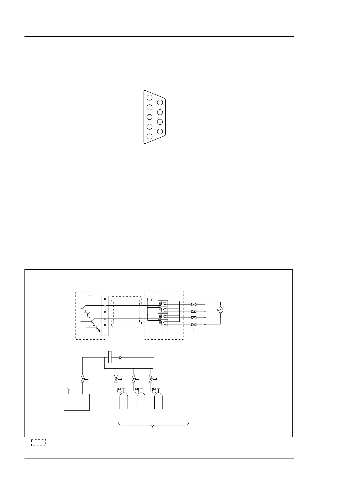
Example of using solenoid valve drive signal output for calibration
<Electrical system>
SV4
Ch1
span
Contact relay
Relay board
Ch2
span
5V
I/O terminal module
<Gas sampling system>
Electronic
gas cooler
9
1
3
4
5
Cable
CN3
Flowmeter
Membrane filter
SV3
SV2SV1
Zero
Standard gas for calibration
SV1
SV2
SV3
SV4
Solenoid valve
drive power
SV1 to SV4: solenoid valves
Refer to Item 3.4.7 Example configuration
of gas sampling system .
3 - 16
Relay board and exclusive cable (D-sub 9p straight cable: 1.5 meters)
are available on request.
IM 11G02N01-01E
Page 30
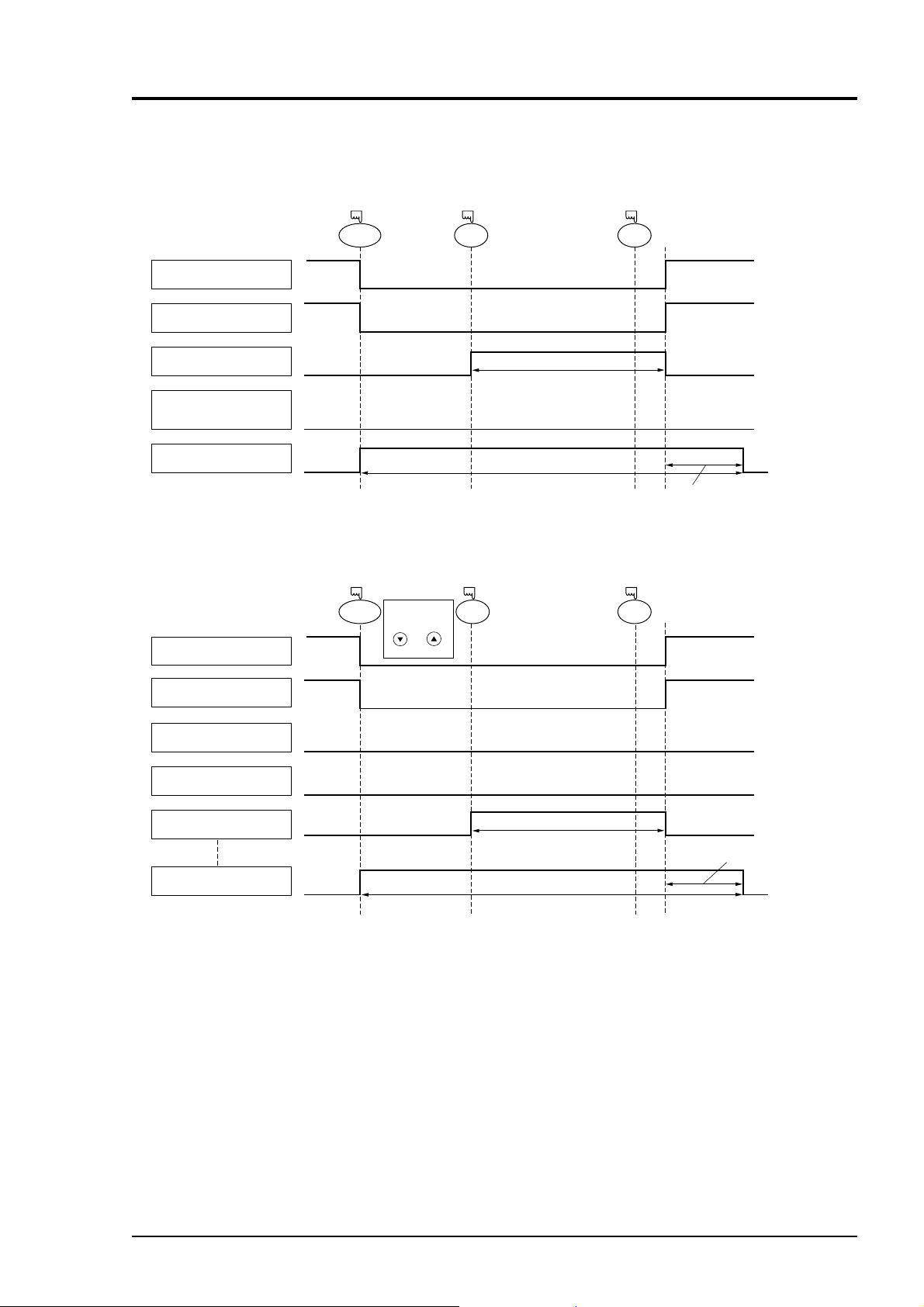
¥ Zero calibration
¥ Span calibration
Zero calibration
output
Zero calibration
output
Pump ON/OFF contact
Pump ON/OFF contact
Sample selection
output
Ch1 to 5 span
calibration output
Ch1 span
calibration
Output hold function
Sample selection
output
(with hold ON setting)
ZERO ENT
ENT
Hold extension time.
Calibration gas flow
Calibration gas flow
Output signal hold
Output signal hold
Calibration end
Calibration end
on
off
on
off
on
off
off
Output hold function
(with hold ON setting)
SPAN ENT
ENT
Hold extemsion time.
Note)
When selecting
Ch2 using
and
keys.
Ch2 span
calibration
The hold extension time
depends on the gas
flow time of the
automatic calibration
settings.
(7) Timing of solenoid valve drive signal for calibration
1. Manual calibration (see “Item 6.9 Calibration”.)
IM 11G02N01-01E
3 - 17
Page 31

2. In case of automatic calibration (example shown in Item 6.4.1, Automatic calibration settings)
Pump ON/OFF contact
Sample selection output
Zero calibration output
Ch1 span calibration output
Ch2 span calibration output
Ch3 span calibration output
Ch4 span calibration output
Ch5 span calibration output
Automatic calibration contact
Output hold function
(with hold ON setting)
Automatic
calibration
start
Zero calibration
Zero gas
350 s
Ch1 span
calibration
Ch1 span gas
350 s
Ch2 span
calibration
Ch3 span
calibration
Ch4 span
calibration
Ch5 span
calibration
Hold
extension time.
3 - 18
IM 11G02N01-01E
Page 32

4. OPERATION
4.1 Preparation for operation
(1) Tube and wiring check
Double-check if tubes of the gas sampling and exhaust ports are correctly connected.
Double-check for proper wiring.
4.2 Warm-up operation and regular operation
(1) Operation procedure
1) Turn ON the power switch on the front panel of the analyzer unit.
The measurement screen appears on the front display panel in 1 or 2 seconds.
2) Wait for about 4 hours until the instrument is warmed up.
About 4 hours are required until the instrument allows accurate measurement.
Note) When in warm-up, the concentration reading may be beyond.
upper limit of range or
But, it is not an error.
3) Setting of various set values
Perform the various settings according to “Chapter 6. Setting and Calibration”.
4) Zero calibration and span calibration
Perform zero calibration and span calibration after warm-up operation.
Refer to “Chapter 6.9. Calibration”.
5) Introduction and measurement of measuring gas
Introduce the measuring gas into the analyzer unit before starting measurement.
lower limit of range.
IM 11G02N01-01E
4 - 1
Page 33

Blank Page
≈
Page 34

5.
DESCRIPTION OF DISPLAY AND OPERATION PANELS
This section describes the display unit and operation panel of the analyzer unit. It also explains the name
and description of function on the operation panel.
5.1 Name and description of operation panel
POWER
Name
(1) MODE key
(2) SIDE key
(3) UP key
(4) DOWN key
MODE
ESC ZERO
ENT SPAN
Fig. 5-1
Description
Used to switch the mode.
Used to change the selected item
(by moving the cursor) and
numeral digit.
Used to change the selected item
(by moving the cursor) and to
increase numeral value.
Used to change the selected item
(by moving the cursor) and to
decrease numeral value.
Name
(5) ESCAPE
key
(6) ENTRY
key
(7) ZERO key
(8) SPAN key
Description
Used to return to a previous screen
or cancel the setting midway.
Used for confirmation of selected
items or values, and for execution
of calibration.
Used for zero calibration.
Used for span calibration.
IM 11G02N01-01E
5 - 1
Page 35

5.2 Overview of display and operation panels
• Measurement mode
MODE
• Measurement mode
• Measurement mode
MODE
MODE
• User mode
ESC
• User mode
Switch Ranges
Calibration Parameters
Alarm Setting
Setting of Auto Calibration
Setting of Auto Zero calibration
Setting of Peak Alarm
Parameter Setting
* 2) The peak alarm setting is
added according to the
code symbol when CO
and O
components exist.
2
ESC
ESCMODE
ESC
ESC
ESC
ESC
ESC
ESC
ESC
ESC
* 1
•
Switch Ranges
• Calibration
Parameters
• Alarm Setting
• Setting of Auto
Calibration
•
Setting of Auto
Zero calibration
• Setting of
Peak Alarm
• Parameter
Setting
* 1) The panel configuration is changed depending on the
display channel. (The measurement mode screen can
be viewed by scrolling the arrow key up and down).
ZERO
ZERO Calibration
SPAN Calibration
SPAN
• Selection of items
Calibration value
Zero calibration
Calibration range
Auto calibration components / range
• Selection of items
Start Time
Cycle
Flow Time
Auto calibration ON/OFF
Auto Calibration Run / stop
• Selection of items
Start Time
Cycle
Flow Time
ON/OFF
Auto zero Calibration Run / stop
• Selection of items
Peak Alarm ON/OFF
Peak Value
Peak Count
Hysteresis
5 - 2
• Selection of items
Current time : Current time setting
Key lock : Key lock ON/OFF
Output Hold : ON/OFF
Reset Av. Output : Average value
resetting
Response time : Response time (filter)
Average Period : Average Period
setting
Backlight Timer : ON/OFF, timeup time
To Maintenance mode: Maintenance mode
(entry of password)
Fig. 5-2
IM 11G02N01-01E
Page 36

5.3 Outline of display screen
C h
C h
C h
C h
C h
(1)
(2)
(3)
(4)
(1)
(2)
(4)(5) (6) (3) (7) (8)
C h
C h
C h
C h
(1) Measurement mode screen (appears when the power is turned ON)
The measurement screen depends on the number of components. The following screen configuration as shown as an example is for NO, SO
* corrected instantaneous value ..... CV.
** corrected average value...............
, CO2, CO and O2 (output: 12 channel).
2
CV.
AV.
Fig. 5-3 Name and function of measurement mode screen
* For outputs of more than 5 channels, scroll the arrow key
No.
(1)
(2)
(3)
(4)
Name
Component
display
Concentration
display
Range display
Unit display
Displays component of instantaneous value, corrected instantaneous value, corrected average
value, etc.
Displays measured value of
concentration.
Displays range values.
Displays unit with ppm and
vol%.
Function
No.
(5)
(6)
(7)
(8)
or to view.
Name
Peak alarm
component
display
Peak alarm
concentration
display
Peak alarm
times
Peak alarm
unit display
Description
Displays peak alarm component.
Displays peak alarm concentration display.
(Upper limit value)
Displays the alarm times
exceeding the peak value.
Displays units of peak alarm with
times/H.
IM 11G02N01-01E
5 - 3
Page 37

• Instantaneous value and concentration value:
The concentration display of Ch (component) where sampling components such as “CO
or “O
are displayed in the component display, indicates current concentration values of the
2
2
measured components contained in gas that is now under measurement.
correction concentration values:
• O
2
Ch components where “cv**” is displayed as “cv CO” in the component display are calculated
from the following equation, by setting sampling components, O
values and O
correction reference value (see item 6.8).
2
instantaneous/concentration
2
On:The value of the O2 correction referance value
Correction output=
21 - On
21 - Os
× Cs
(Value set by application)
Os:Oxygen concentration (%)
Cs: Concentration of relevant measured component.
Note that Os does not exceed the O
limit value
2
”, “CO”
The converted sampling components are NO
••
correction concentration average value:
• O
••
2
In the Ch (component) and O
average value where “ **” is displayed as “ CO” in the
2
component display, a value obtained by averaging O
, SO2 and CO only.
X
CV
AV
correction concentration value or O
2
CV
AV
average value in a fixed time is output every 30 seconds.
Averaging time can be changed between 1 minute and 59 minutes or 1 hour and 4 hours accord-
ing to the average time settings (See 6.7, Parameter setting).
(The set time is displayed as “1h” , for instance, in the range display.)
* The measurement ranges of O
correction concentration value and O2 correction concentra-
2
tion average value are the same as that of the measuring components. Also, the measurement range of O
average value is the same as that of O2.
2
(2) Setting/selection screen
The setting/selection screen is configured as shown below:
• In the status display area, the current status is displayed.
• In the message display area, messages associated with operation are displayed.
• In the setting item and selection item display area, items or values to be set are displayed,
as required. To work on the area, move the cursor to any item by using
keys.
, and
2
5 - 4
Status display area
Cursor
• LCD screen
Message display area
Setting item/selection item
display area
Fig. 5-4
IM 11G02N01-01E
Page 38

Ch12
av.
2
O
av.1, 2, 3
2
O
Correct CO av.
av.
2
T08.EPS
Ch10Ch9 Ch11Ch7Ch6 CH8
Output corresponding to channels
2
CO
CO
SO
CO
av.
2
O
av.
x
CO
Correct NO
x
2
CO
Correct NO
2SO2
2
O
SO
av.
av.
2
2
O
O
av.
2
Correct CO av.
Correct SO
2
av.
2
O
Correct SO
Correct CO
2
2O2
O
O
av.
av.
2
2
O
O
av.
2
Correct CO av.
Correct SO
av.
av.
x
x
av.
2
O
Correct NO
Correct NO
2
Correct SO
Correct CO av.
Correct CO
x
av.
x
Correct NO
Correct CO av.
Correct NO
2
2
2
O
O
O
2
CO
CONO
SO
Correct CO av.
Correct SO
av.
av.
2
x
Correct NO
Correct SO
av.
x
Correct CO
Correct NO
2
Correct SO
Correct CO
x
2
Correct SO
Correct NO
x
2
O
Correct NO
2
O
CO
2
CO
CO
2
2
2
O
SO
SO
2
O
CO
2
O
CO
2
O
CO
2
SO
2
CO O
2
CO
2
SO
.
x
2
2
NONot specifiedN
SO
correction Ch4Ch3Ch1 Ch2 Ch5
2
Not specified
O
N
analyzer
2
O
Code symbol
-B
-A
(3) Contents of measured channel (Ch)
The following table gives measurement channels and their contents according to the symbols.
Measurable component
4
CO
CH
CO
Not specified
Not specified
Not specified
N
NNNNN
-F
-D
-C
2
NO
NONONO
CO
Not specified
Not specified
Not specified
Not specified
N
-J
-K
-H
-G
2
x
CO
SO
NO
/K/K/K
Not specified
N
1, 2, 3
1, 2, 3
1, 2, 3
-L
-A
-B
-D
4
CH
/K
1, 2, 3
-F
xNOxNOx
x
NO
/K
/K
1, 2, 3
1, 2, 3
-H
-G
2
CO
/K
/K
1, 2, 3
-J
-K
CO
except /K/Kexcept /K
1, 2, 3
1, 2, 3
-L
-D
2
NO
CO
except /K
1, 2, 3
1, 2, 3
-J
-H
NO
NO
except /K
except /K
1, 2, 3
1, 2, 3
-K
IM 11G02N01-01E
correction.
2
The "av." means avarage value.
The peak count alarm becomes a contact output.
The "correct" means O
(note) : As for the NO meter within this range, the display on the indicator become NO
5 - 5
Page 39

5.4 General operation
C h
O
2
0-25
vol%
C h
CO
0-100
ppm
C h
CO
2
0-10
vol%
C h
SO
2
0-100
ppm
C h
NO
X
0-100
ppm
00
.
00
.
000
00
.
000
.
.
C h
O
2
0-25
vol%
C h
CO
0-100
ppm
C h
CO
2
0-10
vol%
C h
SO
2
0-100
ppm
C h
NO
X
0-100
ppm
00
.
00
.
000
00
.
000
.
.
ZERO
SPAN
C h
AV.
O2
PEARK COUNTER
CO 500ppm 0 times/H
0-25
vol%
C h
CO
0-100
ppm
C h
SO2
0-100
ppm
C h
NOX
0-100
ppm
000
.
00
.
00
.
00
.
CV.
AV.
CV.
AV.
CV.
AV.
ESC
MODE
• Measurement mode
The measurement mode can be displayed
up to 5 channels in a single screen. If 5
channels or more are to be displayed in a
single screen, press the
scroll the channel one by one.
or key to
Zero calibration
See 6.9.1.
Span calibration
See 6.9.2.
• User mode displays;
Changeover of Range
Setting about Calibration
Alarm Setting
Setting of Auto Calibration
Setting of Auto Zero Calibration
Setting of Peak Alarm
Parameter Setting.
For the setting contents, refer to
“Chapter 6. Setting and calibration”.
5 - 6
IM 11G02N01-01E
Page 40

6. SETTING AND CALIBRATION
6.1 Switch of range
6.1.1 Setting of range switch mode
Set the range switch mode as follows.
MODE
(1) Press the
display the User mode screen.
(2) Move the cursor to “Switch Ranges” and
press the
(3) The “Channel Selection” screen appears.
Move the
the
screen that appears, and select Ch
(component).
(4) Then press the
key in measurement mode to
ENT
key.
cursor by pressing the or
key on the channel selection
ENT
key.
MODE
ENT
(5) Selected range switch mode is highlighted.
Press the
or the key to select a
desired switch mode.
Description of setting
MR: Select a desired range on this screen.
RR: Select a desired range according to
the remote range switch contact input.
AR: Automatically switched from Range 1
to Range 2 when the measured concentration exceeds 90% of Range 1.
Automatically switched from Range 2
to Range 1 when the measured concentration becomes smaller than 80% of
Range 1.
* Operation set for each Ch only can be
performed.
ENT
(6) Then press the
key to confirm the
selection.
If “MR” is selected, the cursor moves to
“Range Switch.”
( )
( )
Range switch
or previous screen
ENT
ENT
IM 11G02N01-01E
6 - 1
Page 41

6.1.2 Manual range switch
The range of the measured component can be
switched manually as follows.
(1) Select “MR” as range switch mode, and
ENT
then press the
key.
(2) Move the highlight of the cursor to range
selection, and then select a desired range
ENT
by pressing the
or the key. (The
mark indicates the currently selected
range.)
(3) Then press the
ENT
key, and the
measurement is carried out in the
selected range.
Note) If “RR” or “AR” is selected as
range switch mode, this operation
cannot be performed.
The range for O
correction average value, and O
O
2
correction value,
2
average value is automatically
switched if corresponding
instantaneous value range is
switched.
To close the setting
Press the key to end the setting of range
ESC
switch mode or range switch operation or stop
the operation in the middle, and the setting
operation is made invalid and the previous
screen appears.
( )
2
End of Range Switch
ENT
6 - 2
Range identification contact operation
The range identification contact output corresponding to each Ch (component) is conductive
when Range 1 is selected, and open when Range 2 is selected, which is applicable to any of
the range switch mode selected.
Note that even if the range is switched during the hold of measurement value by remote hold
contact input or the hold of measurement value at the time of calibration, the range identification contact output maintains the contact state immediately before the hold. After stop of
the hold, the contact state of the current range is resumed.
IM 11G02N01-01E
Page 42

6.2 Calibration setting
This mode is used to set calibration concentration and actions. The calibration setting involves
calibration concentration, zero calibration, calibration range and auto calibration component.
6.2.1 Setting of calibration concentration
It allows you to set concentrations of the standard gas (zero and span) of each channel used for
calibration.
MODE
(1) During measurement, press the
MODE
display the User mode.
(2) Point the cursor to “Calibration
Parameters” by pressing the
Press the
ENT
key.
or key.
(3) In the “Calibration Parameters” screen
that appears, point the cursor to “Calibration Value” by pressing the or
key. Press the
ENT
key.
key to
( )
ENT
(4) In the “Calibration Concentration Ch
Selection” screen that appears, point the
cursor to Ch you want to set by using the
IM 11G02N01-01E
or key. Press the
ENT
key.
( )
( )
ENT
ENT
6 - 3
Page 43

(5) In the “Calibration Concentration Selection”
screen that appears, select any concentration
item you want to set by pressing the
,
key.
Then press the
ENT
key, and the selected
value is highlighted.
(6) In the “Calibration Concentration Value
Setting” screen that appears, enter calibration
gas concentration values (zero and span).
For value entry, press the
or key, and
a 1-digit value increases or decreases. By
pressing the
, the digit moves.
After setting, save the entry by pressing the
ENT
key. The saved value becomes valid
from the next calibration process.
Note) Enter settings that correspond to each
range. If zirconia type is used as O
2
sensor, select 21.00 for the field of Zero
(when air is used), and select the
concentration listed on the cylinder if the
air contained in a cylinder is used.
To close the setting
To close the calibration concentration value
setting process or cancel this mode midway,
press the key.
ESC
A previous screen will return.
Cursor for setting value
End of Calibration
Concentration Setting
ENT
ENT
Setting range of values
NOx, SO2, CO
measurement and buit-in paramagnetic O
2,
CO, CH4, external O2
2
sensor
2
External Zirconia O
measurement
The setting cannot be performed beyond the range.
6 - 4
Span gas: 1 to 105% of full scale
(Full scale (FS) is the same as each range
value.)
Zero gas: 5 to 25 vol%
Span gas: 0.01 to 5 vol%
IM 11G02N01-01E
Page 44

6.2.2 Setting of manual zero calibration
When zero calibration is made manually, set either all measurement components should be
calibrated simultaneously or each component should be calibrated while selecting one by one.
MODE
(1) During measurement, press the
MODE
key
to display the User mode.
(2) Point the cursor to “Calibration Param-
eters” by pressing the
ENT
the
key.
or key. Press
(3) In the “Calibration Parameters” screen that
appears, point the cursor to “About ZERO
Calibration” by pressing the
ENT
Press the
key.
or key.
( )
ENT
(4) In the “Manual ZERO Calibration Ch
Selection” screen that appears, point the
cursor to Ch (component) you want to set
by using the
key.
IM 11G02N01-01E
or key. Press the
ENT
( )
( )
ENT
ENT
6 - 5
Page 45

(5) In the “Manual ZERO Calibration
Selection” screen that appears, select “at
once” or “each” by pressing the
key. When selecting “at once”, the
Ch (components) to be set can be zerocalibrated at the same time. When
selecting “each”, either of the Ch (components) to be selected is zero-calibrated.
ENT
After setting, press the
key.
or
To close the setting
( )
ENT
To close the manual zero calibration setting or to
cancel this mode midway, press the ESC key.
ESC
A previous screen will return.
Manual Zero Calibration Setting
End of
Example
Whether “each” or “at once” can be determined for each Ch (component).
•Setting “each”
Select the Ch (component) on the manual zero calibration screen and then perform
zero calibration.
•Setting “at once”
At a manual zero calibration, zero of Ch (components) for which “at once” was selected can
simultaneously be calibrated.
* When the cylinder air or atmospheric air is used for the zero gas, select “At once.”
Manual Calibration screen
6 - 6
• When setting all components to “each”:
A single cursor will appear.
• When setting all components to “at once”:
Cursors will appear at all components
where “at once” is set.
IM 11G02N01-01E
Page 46

6.2.3 Setting of calibration range
This mode is used to set if the range of each CH (component) at the calibration (manual calibration
or auto calibration) should be calibrated with a single range or 2 ranges.
MODE
(1) During measurement, press the
MODE
key to
display the User mode.
(2) Point the cursor to “Calibration
Parameters” by pressing the
key. Press the
ENT
key.
or
(3) In the “Calibration Parameters” screen
that appears, point the cursor to “About
Calibration Range” by pressing the
key. Press the
ENT
key.
or
( )
ENT
(4) In the “Calibration Range Ch Selection”
screen that appears, point the cursor to the
Ch you want to set by pressing the
IM 11G02N01-01E
key. Press the
ENT
key.
or
( )
( )
ENT
ENT
6 - 7
Page 47

(5) On the “calibration range selection”
screen that appears, select “both” or
“current” by pressing the
or the
key.
• If “both” is selected, zero or span
calibration is performed with Range 1
and Range 2 of the selected Ch
interlocked.
• If “current” is selected, zero or span
calibration is performed only for the
range displayed when calibration of
selected Ch is performed.
Press the
ENT
key after the selection, and
the specified calibration is performed.
To close “Setting of Calibration Range”
To close “Setting of Calibration Range” or
to cancel this mode midway, press the
ESC key. A previous screen will return.
ESC
Example
( )
End of Calibtation Range Setting
ENT
Ch1
NOx
Ch2
SO
Range 1: 0 to 100 ppm
Range 2: 0 to 2000 ppm
Range 1: 0 to 100 ppm
Range 2: 0 to 2000 ppm
2
both
current
Ch1: Range 1 and Range 2 are calibrated together with zero and span calibration.
Ch2: Only currently displayed range is calibrated with zero and span calibration.
Note
To perform calibration for “both,” set the same calibration gas concentration for both
ranges.
Manual Calibration screen
When setting NOx and CO to “both”
6 - 8
Two cursors will appear in both ranges (Ch1 and Ch4).
IM 11G02N01-01E
Page 48

6.2.4 Setting of auto calibration component/range
Select the Ch (component) and the range with which auto calibration is to be performed. The Ch
for which “AR” has been selected as range switch mode is calibrated in the range set here even
when auto calibration is performed.
MODE
(1) During measurement, press the
MODE
key
to display the User mode.
(2) Point the cursor to “Calibration Param-
eters” by pressing the
ENT
Press the
key.
or key.
(3) In the “Calibration Parameters” screen
that appears, point the cursor to “Auto
Calibration Components / Range” by
pressing the
ENT
key.
or key. Press the
( )
ENT
(4) In the “Auto Calibration Components /
Range” selection screen that appears,
point the cursor to the Ch you want to set
by pressing the
IM 11G02N01-01E
ENT
key.
or key. Press the
( )
( )
ENT
ENT
6 - 9
Page 49

(5) The cursor next to the range of the
selected Ch (component) is highlighted.
Select the range to be calibrated mainly
by pressing the
(6) Then press the
or the key.
ENT
key, and calibration is
performed in the selected range.
To close "Auto Calibration
Component/range" setting
Auto calibration and the manual calibration
of the component with which “AR” has
been selected as range switch mode are
performed in the range selected here. In this
case, once the calibration is started, the range
is automatically switched, and on completion
of the calibration, the original range is
resumed.
The range identification contact is interlocked with the range after the switch.
However, if the hold setting is set to “ON,”
the contact status before calibration is maintained.
( )
End of Auto Calibtation
Range Setting
ENT
(7) Press the
key in the state described in
(5), and the highlight is switched between
“enable” and “disable” auto calibration.
(8) Select “enable” of “disable” by pressing
the
(9) Then press the
or the key.
ENT
key.
( )
ENT
To close the setting
Press the key to exit automatic calibra-
ESC
tion component/range setting, and the pre-
End of Auto Calibtation
Component Setting
vious screen appears.
Operation by setting
Auto calibration is performed under the following rules.
1. Zero calibration is performed at the same time, for the Ch (component) with which “enable”
is selected at the time of auto calibration and auto zero calibration.
2. Span calibration is performed in the order from smallest Ch No., for the Ch (component)
with which “enable” is selected at the time of auto calibration.
6 - 10
Note
ZERO calibration on auto calibration and auto zero calibration of the component with
which “enable” is selected are performed in batch irrespective of the description in
“6.2.2 Setting of manual zero calibration.”
IM 11G02N01-01E
Page 50
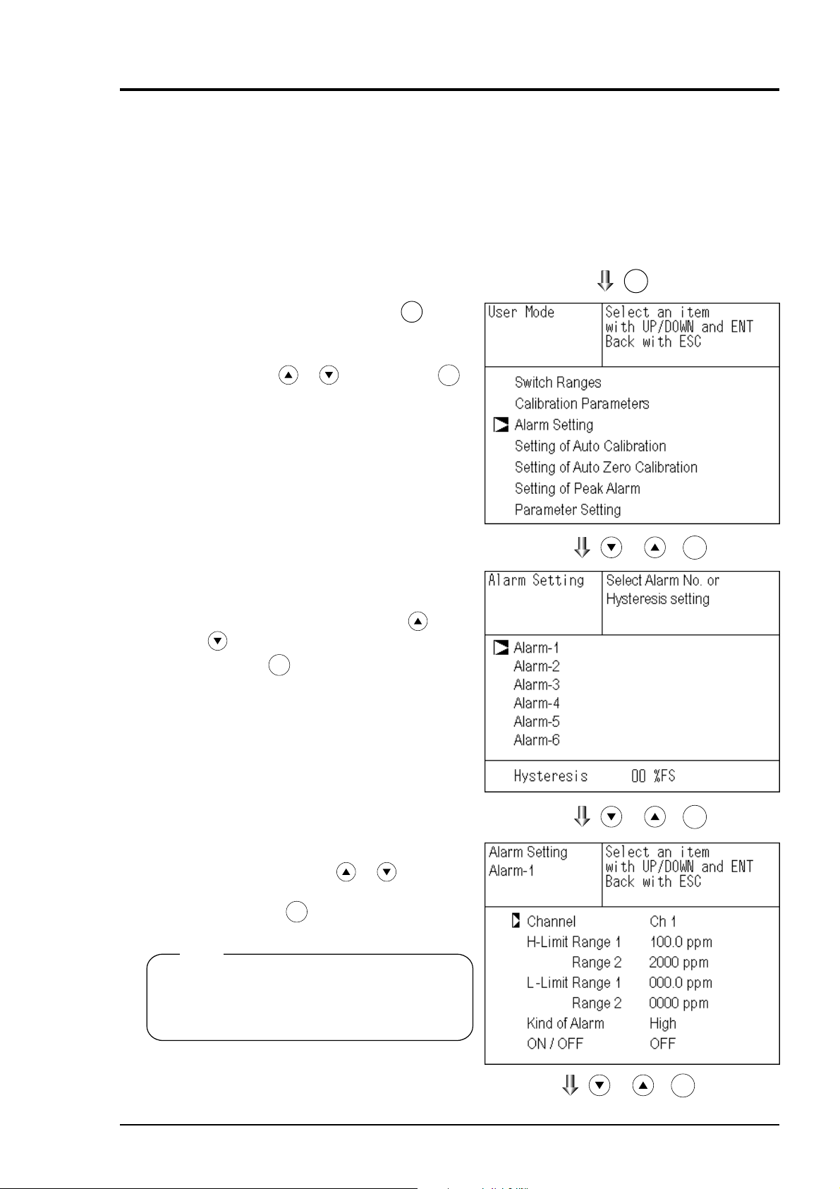
6.3 Alarm setting
6.3.1 Setting of alarm values
The High/Low limit alarm output setting for the measured concentration and power off alarm
(alarm 6 only) setting can be made during measurement. Arbitrary 6 alarm contact outputs can be
used.
To change alarm setting, set the alarm ON/OFF setting to OFF, and then change the value.
MODE
(1) During measurement, press the
MODE
key
to display the User mode.
(2) Point the cursor to “Alarm Setting” by
pressing the
or key. Press the
key.
(3) After the alarm No. selection screen has
appeared, point the cursor to the Alarm
No. you want to set by pressing
or
key .
ENT
Press the
key.
ENT
( )
ENT
(4) After the alarm item selection screen has
appeared, operate the
or key until
the cursor is aligned with a desired item
and press the
ENT
key.
Note
Set the values so that H-limit value > L-limit
-
value and that (H-limit value
L-limit value)
> hysteresis.
IM 11G02N01-01E
( )
( )
ENT
ENT
6 - 11
Page 51

(5) After setting, the alarm setting is now
ENT
completed by pressing the
key.
To close the "Alarm Setting"
To close the “Alarm Setting” or to cancel this
mode midway, press the key.
ESC
A previous screen will return.
Setting range
0% to 100% FS (Settable in each range).
Cursor for setting value
End of Alarm Setting
ENT
Description of setting items
The alarm contact assigned the same number as the alarm is operated accordingly.
Channel: Channel setting targeted for issuance of alarm (Power off alarm can be
selected for alarm 6.) One Ch No. can be selected for multiple alarms.
H-Limit value: Sets the high limit value (concentration) of alarm.
L-Limit value: Sets the low limit value (concentration) of alarm.
Kind of Alarm: Selects one of High limit alarm, Low limit alarm, and High limit or Low
limit alarm, HH limit alarm, and LL limit alarm.
High, HH ... Alarm contact closes when above H-limit alarm.
Low, LL ... Alarm contact closes when below L-limit alarm.
High or Low ... Alarm contact closes when above H-limit value or
below lower limit value.
If “Power” is selected for Channel, the contact is closed at all times while the power is on
irrespective of the setting made here. (Alarm-6 only)
ON/OFF: Enables the alarm function if set at ON, or disables the alarm function if set at OFF.
* The H-limit value cannot be set below the L-limit value, and the L-limit value cannot be set
above the H-limit value.
If it is desired to set the H-limit value below the L-limit value already stored in the memory,
reduce the L-limit value beforehand, and vice versa.
6 - 12
Typical on-screen display when an alarm occurs
When an H-limit alarm occurs, the “H-alarm”
message comes on in the field of relevant
Ch (component).
(“L-alarm” for L-limit alarm, “HH-alarm”
for HH limit alarm, and “LL-alarm” for
LL limit alarm)
C h
NO
H-alarm
0-100
C h
SO
0-100
C h
CO
0-10
C h
CO
0-100
C h
O
0-25
X
2
2
2
Note
For 10 minutes after turning on power, the alarm judgment is inactive.
---00
.
0003
00
.
2100
IM 11G02N01-01E
ppm
.
ppm
vol%
.
ppm
vol%
Page 52
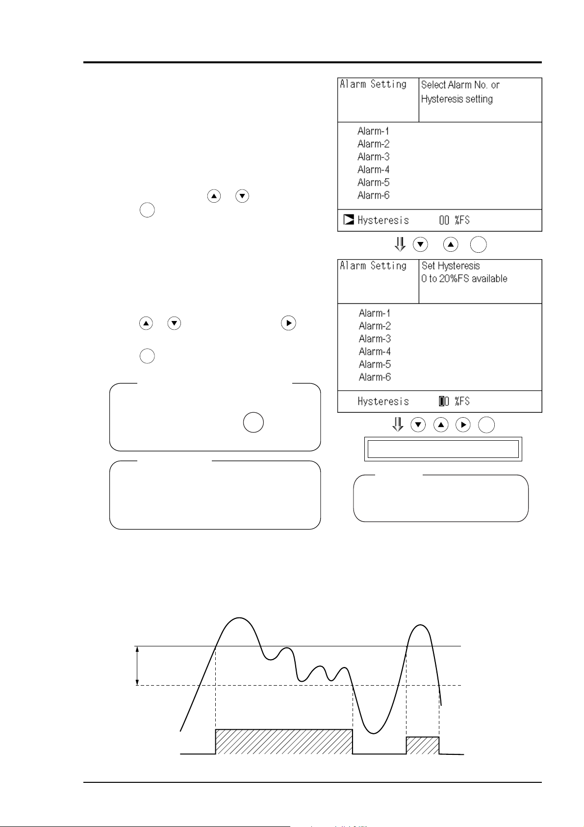
6.3.2 Hysteresis setting
To prevent chattering of an alarm output near
the alarm setting values, set the value
of hysteresis.
(1) In the “Alarm No. Selection” screen that
appears, point the cursor to “Hysteresis”
by pressing the
ENT
key.
or key. Press the
(2) In the “Hysteresis Value Setting” screen
that appears, enter hysteresis values.
For the value entry, 1-digit value is
increased or decreased by pressing the
or key, and pressing the key
moves the digit. After setting, press the
ENT
key.
To close "Hysteresis Setting"
To close the “Hysteresis Setting” or cancel
ESC
the mode midway, press the
ESC
key.
A previous screen will return.
Setting range
0 to 20% of full scale
[% full scale (FS)] represents the percentage
with the width of the range of each component regarded as 100%.
( )
End of Hysteresis Setting
ENT
ENT
Note
The hysteresis is common to all alarms
(components).
Hysteresis (In case of upper limit alarm)
An alarm output is turned ON if measurement value exceeds the upper limit value as shown
below. Once the alarm output has been turned ON, it is not turned OFF as long as the
indication does not fall below the hysteresis width from the upper limit value.
Hysteresis
width
Alarm
Contact output
IM 11G02N01-01E
Upper limit value
ON (conductive)
OFF (open)
6 - 13
Page 53

6.4 Setting of auto calibration
6.4.1 Auto calibration
Auto calibration is automatically carried out at the time when zero calibration and span calibration
are set.
Before changing the setting of auto calibration, set the ON/OFF to OFF.
1. During measurement, press the
to display the User mode.
2. Point the cursor to “Setting of Auto
Calibration” by pressing the or
key. Press the
ENT
key.
MODE
key
MODE
3. In the “Setting of Auto Calibration”
screen that appears, point the cursor to
any item you want to set by pressing the
or key. Press the
ENT
key.
4. In the “Auto Calibration Parameter
Setting” screen that appears, perform the
value entry or the setting. For the value
entry or setting change, use the
or
key. To change the setting, use the
key to move the cursor to the right.
After setting, press the
ENT
key, and
setting of auto calibration is carried out .
Description of setting items
• Start Time : Setting at the first calibration
(day of the week, hour, minute)
• Cycle : A period between the start time of one
calibration and another
(unit : hour/day)
• Flow Time : The time required for replacement by
calibration gas
Time required for replacement of sample
gas after the calibration is completed
(Set by calibration gas. See the next
page.)
• ON/OFF : ON/OFF of auto calibration
( )
( )
ENT
ENT
To close "Setting of Auto calibration"
To close the "Setting of Auto calibration" or cancel
ESC
ESC
this mode midway, press the
key.
A previous screen will return.
6 - 14
End of Aoto Calibration Setting
ENT
IM 11G02N01-01E
Page 54

<Gas flow time> setting
(1) Press the
ENT
key in a state where the
cursor is placed next to “Flow Time,” and
the flow time setting screen shown at right
appears.
(2) On the flow time setting screen that
appears, move the cursor to the gas you
want to change the setting by pressing the
or the key, and then press the
key.
ENT
MODE
(3) The highlighted value can be changed.
Change the value by pressing the
the
the right by pressing the
key, and then move the cursor to
key.
(4) After changing the value, press the
or
ENT
key.
ESC
(5) Press the
key to return to the
automatic calibration setting screen.
Note) Only the Chs used are displayed on
this screen. The Ex. time is the
output signal hold extension time
after the completion of calibration.
It is valid only when the hold setting
is set to “ON.” The Ex. time set
here is also the hold extension time
at the time of manual calibration.
( )
End of Gas Flow Time Setting
ENT
ENT
IM 11G02N01-01E
6 - 15
Page 55

Auto calibration status contact output is closed during auto calibration (including Ex. time), and is open in
other cases.
Example
Start Time
Cycle
Flow Time
ON/OFF
SUN
1
Zero
Ch1 Span
Ch2 Span
Ch3 Span
Ch4 Span
Ch5 Span
EX. time
ON
12:00
day
350 sec
350 sec
350 sec
350 sec
300 sec
300 sec
300 sec
In case where auto calibration is carried out at the above setting.
Sunday
12:00
Zero
calibration
350sec 350sec
Cycle
Ch1
Span
calibration
Monday
12:00
Ch2
Span
calibration
350sec
Ch3
Span
calibration
350sec
Tuesday
12:00
Ch4
Span
calibration
300sec 300sec
Ch5
Span
calibration
Flow time
: Auto calibration
Replacement time
300sec
(An example of “Ch1: through Ch5: enable”, as given in Item 6.2.4 “Auto Calibration
Components/range”)
Setting range
Cycle : 1 to 99 hours or 1 to 40 days (initial value 7days)
Flow time : 60 to 900 sec (initial value 300sec)
Caution
When an auto calibration starts, the measurement screen automatically appears.
•
Any key operation other than key lock ON/OFF and “Stop Auto Calibration” (see
•
Item 6.4.2) is not permitted during auto calibration. “Stop Auto Calibration” cannot
be performed with the key lock to ON. To cancel auto calibration forcedly, set
the key lock to OFF and then execute “Stop Auto Calibration”.
Turn on the power again after it is turned off (including the case of power
•
failure) at the time set as the next start time in auto calibration, and then
repeat it in the set cycle.
Remote start
Whether the auto calibration is set at ON or OFF, an auto calibration is available by keeping the
remote start input closed for at least 1.5 seconds.
Remote start input
6 - 16
Closed (keep at least 1.5 sec.)
Open
IM 11G02N01-01E
Page 56

6.4.2 Forced run/stop of auto calibration
Auto calibration can be performed just once or forcibly stopped while the calibration is
performed.
6.4.2.1 Execution of auto calibration (only once)
(1) Display the User mode screen. Move the
cursor to “Setting of Auto Calibration”
by pressing the
then press the
or the key, and
ENT
key.
(2) In the “Setting of Auto Calibration” item
selection screen that appears, point the
cursor to “Auto Calibration Run” by
pressing the
or key. Press the
ENT
key.
(3) “Run” is highlighted, displaying a mes-
sage to confirm the execution of auto
calibration. Press the
ENT
key to execute
the auto calibration forcibly, and press
ESC
the
key to cancel.
( )
( )
ENT
ENT
IM 11G02N01-01E
6 - 17
Page 57

6.4.2.2 Forced stop of auto calibration
This mode is used to stop the auto calibration forcedly.
(1) In the User mode that is displayed, point
the cursor to “Setting of Auto
Calibration” by pressing the
key. Press the
ENT
key.
or
(2) In the “Setting of Auto Calibration” item
selection screen that appears, point the
cursor to “Auto Calibration Stop” by
pressing the
or key. Press the
ENT
key.
(“Auto Calibration Stop” appears when
the screen is selected while auto calibra
tion is performed.)
(3) “Stop” is highlighted, displaying a
message to confirm the stop of auto
calibration. Press the
ENT
key to stop the
auto calibration forcibly, and press the
ESC
key to cancel (not stopped).
( )
( )
ENT
ENT
6 - 18
IM 11G02N01-01E
Page 58

“Auto Calibration” screen
Example
In case where setting the auto calibration components (see Item 6.2.4) to
“Ch1: enable” and “Ch2: enable”
• Zero calibration
A message, “Zero cal.” blinks
at Ch1 and Ch2.
• Ch1 span calibration
A message, “Span cal.” blinks
at Ch1.
• Ch2 span calibration
A message, “Span cal.” blinks
at Ch2.
C h
NO
ZERO cal.
0-zero100
C h
SO
ZERO cal.
0-100
C h
CO
0-10
C h
CO
0-100
C h
O
2
0-25
C h
NO
SPAN cal.
0-100
C h
SO
0-100
C h
CO
0-10
C h
CO
0-100
C h
O
2
0-25
C h
NO
0-100
C h
SO
SPAN cal.
0-100
C h
CO
0-10
C h
CO
0-100
C h
O
2
0-25
X
2
2
X
2
2
X
2
2
05
.
.
03
.
0000
.
00
2102
.
.
908
.
00
.
000
.
00
000
.
00
.
.
950
.
000
.
00
.
000
ppm
ppm
vol%
ppm
vol%
ppm
ppm
vol%
ppm
vol%
ppm
ppm
vol%
ppm
vol%
Caution
During auto calibration, any key operation is not permitted other than operations such
as key lock ON/OFF and “Stop Auto Calibration.”
When the key lock is set at ON, even the “Auto Calibration Stop” cannot be used.
To stop “Auto Calibration” forcedly, set the key lock to OFF and then execute
“Auto Calibration Stop.”
IM 11G02N01-01E
6 - 19
Page 59

6.5 Setting of auto zero calibration
6.5.1 Autozero calibration
Auto zero calibration is automatically carried
out at the time when zero calibration is set.
Components for which a calibration is to be
made are determined by setting of auto calibration component in Item 6.2.4.
Before changing the setting of auto zero
calibration, set the ON/OFF to OFF.
MODE
(1) During measurement, press the
MODE
key
to display the User mode.
(2) Point the cursor to “Setting of Auto Zero
Calibration” by pressing the
key. Press the
ENT
key.
or
(3) In the “Setting of Auto Zero Calibration”
screen that appears, point the cursor to
any item you want to set by pressing the
or key. Press the
ENT
key.
(4) In the “Auto Zero Calibration Parameter
Setting” screen that appears, perform the
value entry or the setting. For the value
entry or setting change, use the
or
key. To change the setting, use the
key to move the cursor to the right.
After setting, press the
ENT
key, and auto
zero calibration is carried out by the
entered setting value.
( )
ENT
Description of setting items
• Start Time : Setting at the first calibration
(day of the week, hour, minute)
• Cycle : A period between the start time of one
calibration and another
(unit : hour/day)
• Flow Time : The time required for the calibration gas
to be replaced in the cell
• ON/OFF : ON/OFF of auto zero calibration
To close "setting of Auto Zero Calibration"
To close the “Setting of Auto Zero Calibration”
or cancel this mode midway, press the key.
ESC
A previous screen will return.
6 - 20
( )
End of Auto Zero Calibration Setting
ENT
ENT
IM 11G02N01-01E
Page 60

Auto calibration status contact output is closed during auto zero calibration, and is open in other cases.
Example
Start time
Cycle
Flow time
ON/OFF
In case where auto zero calibration is carried out at the above setting.
Sunday
12:00
Zero
calibration
300sec
SUN
12
300
ON
Cycle
Replacement
time
300sec
Flow time
12:00
hour
sec
Monday
0:00
Gas replacement time after calibration is the same as
the flow time.
Monday
12:00
: Auto zero calibration
(An example of “Ch1: through Ch5: enable,” as given in Item 6.2.4 “Auto Calibration
Components/range”)
Setting range
Cycle : 1 to 99 hours or 1 to 40 days (initial value 7days)
Flow time : 60 to 900 sec (initial value 300sec)
Caution
When an auto zero calibration starts, the measurement screen automatically appears.
•
Any key operation other than key lock ON/OFF and "Stop Auto Zero Calibration"
•
(see Item 6.5.2) is notpermitted during auto zero calibration. “Stop Auto Zero Calibration” cannot be performed with the key lock to ON. To cancel auto zero calibration
forcedly, set the key lock to OFF and then execute “Stop Auto Zero Calibration.”
If the auto calibration period and auto zero calibration period have
•
overlapped, the auto calibration is retained, ignoring the auto zero calibration
of that period.
When the hold setting is set to ON, the hold time of auto calibration contact
and measurement value output signal is extended after calibration for gas
•
replacement time.
Turn on the power again after it is turned off (including the case of power
failure) at the time set as the next start time in auto zero calibration, and then
•
repeat it in the set cycle.
IM 11G02N01-01E
6 - 21
Page 61

6.5.2 Forced run/stop of auto zero calibration
Auto zero calibration can be performed just once, or auto zero calibration can be forcibly stopped
during calibration.
6.5.2.1 Execution of auto zero calibration (just once)
(1) Move the cursor to “Setting of Auto Zero
Calibration” by pressing the
or the
key on the user mode screen, and
ENT
then press the
key.
(2) In the “Setting of Auto Zero Calibration”
item selection screen that appears, point
the cursor to “Auto Zero Calibration
Run” by pressing the
ENT
Press the
key.
or key.
(3) “Run” is highlighted, displaying a mes-
sage to confirm execution of auto zero
calibration. Press the
ENT
key to execute
the calibration forcibly, and press the
ESC
key to cancel.
( )
( )
ENT
ENT
6 - 22
IM 11G02N01-01E
Page 62

6.5.2.2 Forced stop of auto zero calibration
This mode is used to cancel the auto zero calibration forcedly.
(1) In the User mode that is displayed, point
the cursor to “Setting of Auto Zero
Calibration” by pressing the
key. Press the
ENT
key.
or
(2) In the “Setting of Auto Zero Calibration”
item selection screen that appears, point
the cursor to “Auto Zero Calibration
Stop” by pressing the
Press the
ENT
key.
or key.
(“Auto Zero Calibration Stop” appears
when the screen is selected while auto
zero calibration is performed.)
(3) “Stop” is inverted. A message appears,
prompting you to verify that you want to
stop auto zero calibration. Press the
ENT
key to stop the auto zoro calibration
forcibly, and the
ESC
key to cancel (not
stopped).
( )
( )
ENT
ENT
IM 11G02N01-01E
6 - 23
Page 63

“Auto Zero Calibration” screen
Example
In case where setting the auto calibration components (see Item 6.2.4) to
“Ch1: enable” and “Ch2: enable”
• Zero calibration
A message, “Zero cal.” blinks
at Ch1 and Ch2.
C h
ZERO cal.
ZERO cal.
C h
ZERO cal.
ZERO cal.
C h
C h
.
C h
0-100
0-100
0-10
0-100
0-25
05
.
.
03
.
000
.
00
2102
.
ppm
ppm
vol%
ppm
vol%
Caution
During auto zero calibration, any key operation is not permitted other than operations such
as key lock ON/OFF and “Stop Auto Zero Calibration.”
When the key lock is set at ON, even the “Stop Auto Zero Calibration” cannot be used.
To stop “auto zero calibration” forcedly, set the key lock to OFF and then execute
“Auto Zero Calibration Stop.”
6 - 24
IM 11G02N01-01E
Page 64

6.6 Peak alarm setting
When the peak number of times CO concentration exceeds the upper limit value during measurement exceeds the set number, an alarm is provided.
The peak alarm and this setting screen appear only when an option is added.
MODE
1. Press the
MODE
key in the Measurement
mode, and the User mode appears.
2. Point the cursor to “Setting of Peak
Alarm” by pressing the
Press the
ENT
key.
or key.
3. In the “Peak Alarm Setting” item selec-
tion screen that appears, point the cursor
to any item you want to set by pressing
the
or key. Press the
ENT
key.
( )
ENT
4. Then, enter numeric values and perform
the setting.
Entering the numeric values or setting the
items should be carried out by using the
or key.
ENT
After setting, press the
key, and the set
values are saved.
Description of setting items
• Peak Alarm : ON/OFF of peak alarm
• Alarm Value : If measuring value exceeds the
set alarm value, a peak counter counts
1 time.
• Alarm Count : When a peak in excess of the setting
time occurs, a peak count alarm output
is provided.
• Hysteresis : To prevent possible chattering
when the measuring value may exceed
the set peak concentration by only
1 time, the peak count has an
allowance in the hysteresis width.
( )
( )
End of Peak Alarm Setting
ENT
ENT
IM 11G02N01-01E
6 - 25
Page 65

Setting range
Alarm value : 10 to 1000 ppm 5 ppm step (initial value: 500 ppm)
Alarm count : 1 to 99 times (initial value: 5 times)
Hysteresis : 0 to 20 % of full scale (initial value: 0% of full scale)
[% full scale] represents the percentage with the CO range regarded as 100%.
Action of peak alarm
Example
If CO concentration exceeds the alarm value, counting will begin. If the number of peaks is over
the set times per hour, a peak alarm contact output becomes closed (ON). If it is less than the set
times per hour, it is open (OFF). Since 5 times of peaks /hour is marked at (1) section from
the above graph, the peak count alarm is turned ON. Since peaks of more than 5 times per 1 hour
occur at the interval between (1) and (2) , the peak count alarm remains ON. Since at (2),
peaks are reduced to 4 times per hour, it is turned OFF.
Like the hysteresis of the alarm setting , the hysteresis prevents possible chattering when
measured gas is fluctuated near the alarm value.
* For 10 minutes after the power is turned ON, a peak alarm counting is not carried out.
Releasing peak count alarm
To release the peak count alarm, set the peak alarm to OFF.
Turning on the peak alarm initiates counting from 0.
6 - 26
IM 11G02N01-01E
Page 66

6.7 Parameter setting
• Current Time : Current year, month, date, day of the week, hour, and minute setting
(The display appears in this order.)
Note: The clock backup time is 2 days. If power is turned on after it is kept off
for 2 days or longer, make the time setting again.
• Key Lock : Sets with ON/OFF so that any key operation except the key lock OFF cannot be
performed.
• Output Hold : Sets whether Calibration Output is held or not, and the holding value setting.
• Reset Av. Output : Resets the average value.
• Response time : Sets the response time of electrical system.
• Average Period : Sets the moving average time.
• Backlight Timer : Sets automatic OFF of the backlight of display unit and the time until backlight out.
• Maintenance mode : Enters passwords to switch to the Maintenance mode.
Description of setting items
It allows you to carry out the parameter setting such as time, key lock, etc., as required. Items to be
set are as follows:
* For the maintenace mode, see Item 6.8.
(1) To display the User mode, press the
key in the measurement mode.
(2) Point the cursor to “Parameter Setting”
by pressing the
ENT
key.
or key. Press the
(3) In the “Parameter Setting” screen that
appears, point the cursor to any item you
want to set by pressing the
key. Press the
ENT
key.
or
MODE
MODE
( )
ENT
( )
IM 11G02N01-01E
ENT
6 - 27
Page 67

4. In the Parameter Setting screen that
appears, enter the numeric values and set
the items. Entering the numeric values or
setting the items should be carried out by
using the
cursor to the right, press the
After setting, press the
or key. To move the
key.
ENT
key, that the
parameter setting is carried out with the
value you set.
To close Parameter Setting screen
To close the “Parameter Setting” screen
or cancel this mode midway, press the
ESC
key.
A previous screen will return.
End of Parameter Setting
Setting Range
• Hold setting : 0 to 100% FS
• Response time : 1 to 60sec. (initial value: 15 sec)
• Average period : 1 to 59 min or 1 to 4 hours (initial value: 1 hour)
When setting the unit of 1 to 59 minutes is terms of minute
or 1 to 4 hours with hour
• Backlight Timer : 1 to 60 min (initial value: OFF)
• Maintenance mode : 0000 to 9999 (initial value: 0000)
ENT
Output Hold
By setting an output hold to ON, an output signal of each channel are held during the calibration
(manual calibration and auto calibration) and for the gas flow time (refer to Item 6.4, Setting of
Auto Calibration). Regardless of Hold ON/OFF setting, an output signal can be held via an
external input.
(1) Manual calibration
ZERO
Calibration
Output hold
or
SPAN
Press the key to flow gas.
To execute calibration, press the ENT key.
ENT
ENT
Hold extending
time.
Time set to gas flow time (See Item 6.4 Auto Calibration.)
6 - 28
IM 11G02N01-01E
Page 68

(2) Auto calibration
Auto calibration start Auto calibration end
Calibration
Output hold
(3) External hold
Remote hold Input
Output hold
Time hold set to the gas flow time
Close
Open
Hold extending time.
(4) Screen display during Holding
The “on Hold” message blinks on the measuring screen.
Since the screen displays the process of calibration is displayed during the manual calibration,
“on Hold” is not displayed even if the output signal is held, but the screen is displayed with the
hold extending time.
(5) If calibration is cancelled after the calibration gas is supplied regardless of during manual
calibration or auto calibration, the holding extending time will be performed.
IM 11G02N01-01E
6 - 29
Page 69

(6) You can select the value for hold from the value immediately before entering output hold,
“current,” and arbitrary value, “setting.”
Follow the procedures shown below to make the setting.
1) Press the
ENT
key in a state where the
cursor is placed next to Hold.
2) “ON” or “OFF” is highlighted. Press the
or the key to select ON or OFF.
ENT
Press the
key to return to (1).
ENT
3) Press the
key in a state ON/OFF is
highlighted, and “Current” or “Setting” is
highlighted. Select “Current” or
“Setting” by pressing the
or the
key.
ENT
4) Press the
key while “Current” is
selected to return to (1). Press the
key while “Setting” is selected to go to
the setting entering screen.
“Current”: Holds the value immediately
before the hold.
“Setting”: Holds the value arbitrarily set.
ENT
( )
ENT
6 - 30
IM 11G02N01-01E
Page 70

5) On the parameter hold screen that
appears, move the cursor next to the Ch
(component) you want to make the
setting by pressing the
and then press the
ENT
key.
or the key,
( )
ENT
6) The value is highlighted, indicating that
the value can be changed. Change the
value by pressing the
or the key,
and then move the cursor to the right by
pressing the
key.
7) After the value is changed, press the
key.
Meaning of setting
The setting is expressed in % against the range
for both ranges.
When 0 to 1000 ppm is selected as the range,
for example, if 10% FS is selected as hold
setting, the output equivalent to 100 ppm is
output and held irrespective of the measurement value at that time.
ESC
8) Press the
key to return to the
parameter setting screen.
ENT
( )
End of Hold Setting
ESC
Parameter Setting screen
ENT
ENT
Description of setting
• Instantaneous value display of the measurement cannot be held. (Output only can be held.)
• If set value is selected for hold, instantaneous O
correction value is calculated and held
2
based on the set value.
• Range identification contact output cannot be switched even if the range is switched during
the hold.
IM 11G02N01-01E
6 - 31
Page 71

Average value reset
This mode is used to clear all average values O
correction average and O2 average, and restarts
2
averaging. All average values are reset at a time. The indication value and output value is 0 ppm,
vol% or so at the time of the reset input (Refer to the average peripd).
Close (hold at least 1.5 sec.)
Reset input
So long as close, resetting lasts.
At the edge of changing from closing to opening, the average action restarts.
Open
Response time
The response time of the electrical system can
be changed.
Setting is available by components.
Note) It does not provide exact seconds for
the setting time, but it gives a guide
of the setting time.
The setting value can be modified as
requested by the customer.
Average period
It allows you to set an average period of the
average value of O
correction and O2 average.
2
It enables you to set an average time of 1 to 59
minutes (1-minute step) or 1 to 4 hours (1-hour
step).
Changing the setting resets the average value
of O
correction and O2 average value.
2
ENT
(Pressing the
validates the resetting only
for components whose setting was changed.)
6 - 32
IM 11G02N01-01E
Page 72

Example of average action
In case the average period was set to 1 hour.
Reset
Average value
Time
1 Time
• Sampling occurs every 30 seconds.
• Every 30 seconds, the average for last 1 hour (time setting) is output.
• At the instant of resetting, zero is assumed for all past values. It means that the average value
will not be correct for 1 hour after resetting.
Backlight Timer
Automatic OFF setting of the backlight of the LCD unit can be made.
When the specified time elapses from when the measurement screen is resumed, the backlight is
automatically turned off. Press any key to reset backlight OFF.
Only when ON is selected, the time until
auto OFF is displayed. Press the key in
this state, and the time setting can be
changed by pressing the
ENT
Press the
key to confirm the selection.
or the key.
If OFF is selected, the backlight is not turned
off.
Maintenance mode
Enter the password and then press the
ENT
key to enter the maintenance mode. The password can
be set by the password setting in maintenance mode. Default password setting at the time of
delivery from the factory is “0000.” You can enter the maintenance mode with the value before it
is changed.
IM 11G02N01-01E
6 - 33
Page 73

6.8 Maintenance mode
This mode is used for check of sensor input values, display of error log files or setting of passwords, etc. First, enter a password and then use it from the next operation. This mode is displayed
by selecting the Maintenance Mode from “Item 6.7 Parameter Setting”.
(1) Select the Maintenance mode from the
Parameter Setting screen to display the
Password Setting screen.
(2) Enter the password, and the Maintenance
Mode item selection screen will be
displayed. Point the cursor to the item
you want to set by pressing the
key and press the
ENT
key.
(3) Next, each Maintenance screen is
displayed.
Note) “To Factory Mode” is used for our
service engineers only. Refrain from
using this mode.
(4) Press the
ESC
key to return to the
Maintenance Mode item selection screen
from each screen.
or
( )
Each “Maintenance” screen
ENT
Description of Sensor Input Value screen
• NOx M : NOx sensor input value
• NOx C : NOx interference compensation
sensor input value
• SO
2
M:SO2 sensor input value
• SO
2
C:SO2 interference compensation
sensor input value
2
M:CO2 sensor input value
• CO
• CO
2
C:CO2 interference compensation
sensor input value
• CO M : CO sensor input value
• CO C : CO interference compensation
sensor input value
• Temperature: temperature sensor input value
• O
2
:O2 sensor input value
• Error Log screen
Description of Error Log screen
Error history. Fourteen newest errors are logged.
For error number, date and time (year, month, day,
period) of occurrence, channel and other details of
error, refer to Item 8.1 Error message.
Select Clear Error Log and press the key, and
ENT
the error log is cleared completely.
6 - 34
IM 11G02N01-01E
Page 74

• Calibration Log screen
Description of Calibration Log screen
Past calibration history.
Sensor input value, concentration value, and
the date when zero/span calibration is performed
are logged. The 10 newest calibration data is
logged by each component.
Move the cursor to Clear Calibration Log and
press the key, and the calibration log is
ENT
cleared completely.
Z1 : Zero calibration (Z) of Range 1
S1 : Span calibration (S) of Range 1
M : Value of measuring detector at the time
of calibration
C : Value of the interference compensation
detector at the time of calibration
Con : Concentration value displayed before
calibration
ENT
Caution
If the following operation is maladjusted, the measurement may be adversely and excessively
affected. Carry out the operation with utmost attention.
. Optical adjustment screen
For details of this item, refer to “Item 7.3.3
Optical zero adjustment method”.
ENT
Press
key and turn ON the solenoid
valve signal for each calibration gas
by using the
or key.
IM 11G02N01-01E
6 - 35
Page 75

• Moisture interference adjustment screen
For details of this item, refer to “Item 7.3.4
Moisture interference adjustment method.”
Description of moisture interference
adjustment screen
In values on the left side of screen, the moisture
interference for each component is already offset.
The figures at right are interference compensation
coefficients.
Move the
nent) by pressing the
then press the
cursor to a desired Ch (compo-
or the key, and
ENT
key, and the selected value
at right is highlighted.
Check that the gas for moisture interference
compensation is flowing, change the moisture interference compensation coefficient
using the
or the key, adjust the value
at left so that it becomes near zero, and then
press the
ENT
key to log moisture interfer-
ence compensation value.
Caution
Since an interference compensation detector
is not provided if the 1st range is beyond 0 to
10 vol%, no interference adjustment can be
performed (no need).
ENT
6 - 36
IM 11G02N01-01E
Page 76

• Output adjustment screen
Description of output adjustment screen
Analog output adjustment screen.
Connect the digital multi meter to the output
terminal corresponding to the number of OUT
to be adjusted, and adjust the value so that 4mA
or 0V is output at zero and 20mA or 1V is
output at span.
Move the cursor using the , , or the
key to the output (OUT No. and zero/
span) to be adjusted, and then press the
ENT
key.
The selected value is highlighted. Adjust
the value, while watching the output, by
pressing the
or the key. Press the
key to select the next digit.
On completion of the adjustment, press
ENT
the
key.
ENT
IM 11G02N01-01E
6 - 37
Page 77

• Other parameter
Description of each setting screen
Password Set : Set the password used to move
from the parameter setting screen
to the maintenance mode.
Arbitrary 4-digit number can be
selected.
2
ref. Value
O
:Set the oxygen concentration
reference value at the time of
oxygen correction calculation.
Settable in the range from 00 to
19%.
Limit :Set the oxygen concentration limit
at the time of oxygen correction
calculation. Settable in the range
from 01 to 20%.
2
* Refer to the O
correction concentration
value in “5.3 Outline of display screen” for
oxygen correction calculation procedure.
Station No. : Set the station No. for MODBUS
communication. Settable
in the range from 00 to 32.
Range setting : Moves to the screen on which
measuring range is changed.
Press the or the key to move the
cursor to the item whose setting is to be
changed.
The values for password, oxygen
correction, limit, and station No. are
highlighted.
Press the
or the key to change the
value to desired one, and then press the
ENT
key.
Note: Pay attention not to forget the
password. Otherwise you cannot
enter the maintenance mode.
6 - 38
IM 11G02N01-01E
Page 78

<How to set/change the range>
The measuring range can be arbitrarily selected in
the minimum and the maximum range specified at
the time of purchase. The range to be used can be
selected 1 or 2.
(1) Move the cursor to the item to be set by press-
ing the
ENT
key.
or the key, and then press the
(2) Move the cursor to the Ch (component) whose
setting is to be changed by pressing the
the
key, and then press the
ENT
key.
or
(3) Move the cursor to the item whose setting is to
be changed by pressing the
ENT
and then press the
key.
or the key,
Settable range
( )
( )
ENT
ENT
The value for range 1 and range 2 must fall within
the range from the MIN and the MAX range
(including the MIN and the MAX range), and
at the same time range 1 must be smaller than
range 2.
The number of ranges is 1 or 2.
(4) Press the
value. Press the
or the key to change the
key to select the next
digit. In a state where the decimal point is
highlighted, press the
or the key, and
the decimal point position can be changed.
(5) When necessary change is made, press the
key.
IM 11G02N01-01E
ENT
End of Set/Change the Range
ENT
ENT
6 - 39
Page 79

6.9 Calibration
6.9.1 Zero calibration
It is used for zero point adjustment. For zero
calibration, gas suited for an application
should be used according to “(3) Standard gas
in Item 3.3 Sampling.”
(1) Press the
screen to display the Manual Zero Calibration screen.
(2) Select the Ch (component) to be
calibrated by pressing the
After selection, press the
zero gas will be supplied.
ZERO
key on the Measurement
or key.
ENT
key, and
ZERO
Caution
For the Ch (components) that is set to
“both” in the “Zero Calibration” of the
Calibration Setting mode, zero calibration
is also carried out at the same time.
(3) Wait until the indication is stabilized
with the zero gas supplied. After the
indication has been stabilized, press the
ENT
key. Zero calibration in range
selected by the cursor is carried out.
Note: For the Ch (component) for
which “AR” is selected in “6.1.1
Setting range switch mode,”
the cursor automatically moves
to the range selected in “Setting
of auto calibration component/
range” (6.2.4), and calibration is
carried out within that range.
( )
ENT
ENT
To close "Zero Calibration"
To close the “Zero Calibration” or
cancel this mode midway, press the
key. A previous screen will return.
6 - 40
ESC
ESC
To Measurement screen after
executing Manual Zero Calibration
IM 11G02N01-01E
Page 80

6.9.2 Span calibration
It is used to perform a span point adjustment. Supply calibration gas with concentration set to the
span value to perform the span calibration. For the span calibration gas for the NOX, SO2, CO2,
CO measurement, use the standard gas with a concentration of 90% or more of the range value.
For the span calibration gas for the O
90% or more of the range value when measuring with the built-in O
gas of 1to 2 vol% when measuring with an external zirconia O
(1) Press the
SPAN
screen to display the Manual Span Calibration screen.
measurement, use the standard gas with a concentration of
2
key on the Measurement
sensor, and use the standard
2
sensor.
2
SPAN
(2) Select CH (component) to be calibrated by
pressing the
or key and press the
key. The calibration gas is supplied.
Caution
When “both” from “Calibration Range” of the
Calibration Setting mode is set, span calibration is performed together with 2 Ranges.
(3) Wait until the indication is stabilized in the
state where the calibration gas is supplied.
After the indication has been stabilized,
press the
ENT
key. Span calibration of
Range selected by the cursor is performed.
Note: For the Ch (component) for
which“AR” is selected in “6.1.1
Setting range switch mode,” the
cursor automatically moves to the
rangeselected in “Setting of auto
calibration component/range”
(6.2.4), and calibration is carried
out within that range.
ENT
( )
ENT
To close "Span Calibration"
To close the “Span Calibration” or cancel
this mode midway, press the key.
A previous screen will return.
IM 11G02N01-01E
ESC
ENT
To Measurement screen after
executing Manual Span Calibration
6 - 41
Page 81

Blank Page
≈
Page 82

7. MAINTENANCE
7.1 Daily check
(1) Zero calibration and span calibration
1. Perform zero calibration. For the calibration procedures, refer to “Item 6.9.1 Zero calibra-
tion”.
2. Then, perform span calibration. For the calibration procedures, refer to “Item 6.9.2 Span
calibration”.
3. Zero calibration and span calibration should be carried out once a week, as required.
(2) Flow rate check
1. Sampling gas flow and purge gas flow are as follows:
• Sampling gas flow: 0.5 ± 0.2L/min
• Purge gas flow: About 1L/min
2. Check and maintenance should be carried out every day, as required.
7.2 Daily check and maintenance procedures
Table 7.1 Maintenance and check table
IM 11G02N01-01E
7 - 1
Page 83

7.3 Maintenance of analyzer unit
7.3.1 Cleaning method for sample cell (pipe cell)
This section is strictly factory adjusted. Handle it with utmost attention.
If it is absolutely required, contact us.
(1) Turn off the power switch, stop the
sample gas, and allow the zero gas to
flow for several minutes to purge the
cell interior.
Loosen the setscrew (2 pieces) from
the top cover and remove it.
(2) Remove the internal gas inlet tube.
(3) Loosen both right and left screws for
cell holding plate.
• Remove the sample cell only.
(4) Turn to the left the sample cell window
and remove it from the sample cell (see
Fig. 7-1).
(5) For cleaning the window and cell
inside surface, first eliminate coarse
dust by soft brush or the like and then
wipe them by soft rag.
The window is easy to get scratched.
Pay utmost attention so as not to
damage it.
(6) After the end of sample cell cleaning,
mount the cell in place and proceed to
running.
After cleaning sample cell, be sure to
perform optical zero adjustment (see
Item 7.3.3) and moisture interference
compensation adjustment (see Item
7.3.4).
Top cover
Screw
Cell holding
plate
Gas outlet
F10.12E.eps
Screw
Sample cell
Cell holding
plate
Gas inlet
Reference cell
Caution
If the window or the cell interior is very dirty, use a soft cloth moistened with absolute alcohol.
A slightly corroded infrared transmission window or sample cell can be remedied by gently rubbing
with chromium oxide powder on cleaning cloth but an excessively corroded one must be replaced.
When cleaning, do not exert an excessive stress.
7- 2
IM 11G02N01-01E
Page 84

Infrared
transmission
window
Window holder
O ring
Sample gas inlet
Cell
Bonded together
Sample gas outlet
Fig. 7-1 Structure of sample cell (pipe cell)
IM 11G02N01-01E
7 - 3
Page 85

7.3.2 Cleaning method for sample cell (block cell)
(1) Turn off the power switch, stop the
sample gas, and allow the zero gas to
flow for several minutes to purge the
cell interior.
Loosen the setscrew (2 pieces) from
the top cover and remove it.
(2) Remove the internal gas inlet tube.
(3) Loosen the 2 detector set bolts.
Note) The distribution cell, block cell
and detector are fastened by the
same bolts.
(4) Using the furnished cell mounting tool,
turn the window fixture to the left and
remove it from the cell. (See the
structure of sample cell (block cell) in
Fig. 7-2.)
(5) For cleaning the infrared transmission
window and cell inside surface, first
eliminate coarse dust by soft brush or
the like and then wipe them by soft rag.
The window is easy to get scratched.
Pay utmost attention so as not to
damage it.
(6) After the end of sample cell cleaning,
mount the cell in place and proceed to
running.
After cleaning sample cell, be sure to
perform optical zero adjustment (see
Item 7.3.3) and moisture interference
compensation adjustment (see Item
7.3.4).
Top cover
F10.12E.eps
Gas inlet tube set cap nut
Detector set bolt
Infrared transmission window
Inner O ring
Outer O ring
O ring holder
Window fixture
Caution
If the window or the cell interior is very dirty, use a soft cloth moistened with absolute alcohol.
A slightly corroded infrared transmission window or sample cell can be remedied by gently rubbing
with chromium oxide powder on cleaning cloth but an excessively corroded one must be replaced.
When cleaning, do not exert an excessive stress.
7- 4
IM 11G02N01-01E
Page 86

Cell mounting tool
Window fixture
O ring holder
Outer O ring
Inner O ring
Infrared transmission window
Sample gas outlet Sample gas inlet
Sample cell unit
Structure of sample cell (of 32, 16, 8, 4, 2 mm long)
Note) Use the dedicated cell mounting tool (furnished).
Reference cell unit
Hole for bolt
for fixing together with
distribution cell and detector
(sample cell and reference cell are integrated)
Fig. 7-2 Structure of sample cell (block cell)
IM 11G02N01-01E
7 - 5
Page 87

7.3.3 Optical zero adjustment method (optical balance adjustment) Caution
If the following operation is maladjusted, the measurement may adversely be affected. If you are
not trained for adjustment, do not carry out this operation but contact the distributor or our serviceman.
The adjustment is performed at reassembly after removing the sample cell, etc. for cleaning, etc.
(1) Remove the top cover. Allow dry N
2
or air to flow through the analyzer unit
sample gas inlet until the reading
stabilizes. The sample gas is introduced
directly to the INLET of analyzer unit
through the gas cylinder.
(2) Proceed to an optical adjustment in the
maintenance mode. The display on the
operation panel of the main unit is as
illustrated on the right. Balance adjustment is not required if the display falls
within ±100.
Piping at optical balance adjustment
Optical system 2
(measuring unit 2)
Short
(not required
for measuring
unit 1 only)
Introduce directly from cylinder
a
b
c
d
Open
Optical system 1
(measuring unit 1)
e
f
g
h
7- 6
<Correspondence between measurement detector and indicated position>
No. of components
to be measured
1-component meter
NO-SO
2
CO2-CO
NO-CO
2-component meter
3-component meter
NO-SO
-CO
2
4-component meter
NO-SO2-CO2-CO
* O
is excluded from the number of components.
2
a
Main
NO
Main
CO
Main
b
Comp
NO
Comp
CO
2
2
Comp
NO
MainNOComp
NO
MainNOComp
NO
MainNOComp
c
—
SO
Main
CO
Main
d
—
SO
2
Comp
CO
Comp
——
SO
Main
SO
Main
SO
2
Comp
SO
2
Comp
e
—
2
—
—
CO
MainCOComp
CO
2
MainCOComp
CO
2
Main
f
—
—
—
2
—
* Main is signal input value from the main detector of each component.
Comp is signal input value from interference compensation detector of each component.
If low range exceeds the range of 0 to 10vol%, detector signal of comp is not usable.
Sensor values of which are not included in measuring components should be ignored.
g
—
—
—
h
—
—
—
——
——
CO
MainCOComp
IM 11G02N01-01E
Page 88

(3) Carry out the adjustment in the procedure in (4) and subsequent.
Dimmer plate
Detector set bolt
• Adjust on the primary side of the optical system so that the values for a to d in 1-1 and
1-2 become as close to 0 as possible within ±100 range.
• Adjust on the secondary side of the optical system so that the values for e to h in 2-1 and
2-2 become as close to 0 as possible
within ±100 range.
Optical zero adjustment knob
(4) Operate the optical zero adjustment
knob to change the value displayed at
a (or e ).
(5) Move the dimmer plate sideview to
change the value displayed at b (or
f ).
(6) Move the dimmer plate sidewise to
change the value displayed at c (or
g ).
(7) Move the dimmer plate sidewise to
change the value displayed at d (or
h ).
(8) Repeat the procedures in (4) to (7) to
make all the displayed values come
close to 0 as possible within ±100
range.
* Adjust the dimmer plate which is
the nearest to the zero adjustment
knob first, and sequentially.
Optical system 2
Optical
system 1
7.3.4 Moisture interference compensation adjustment method
If the following operation is maladjusted, the measurement may adversely be affected. If you are
not trained for adjustment, do not carry out this operation but contact the distributor or our serviceman.
(9) After the optical balance adjustment, mount the top cover of the analyzer unit, then carry out
a moisture interference compensation adjustment, and perform zero and span calibrations.
* Before moving the dimmer plate, loosen the detector set bolts (just enough to make
the plate movable for snug adjustment).
Caution
Proceed to an adjustment if excessively (beyond ± 2%
FS) affected by moisture inteference.
After the end of optical balance adjustment, be sure to
carry out moisture inteference compensation adjustment.
(1) After warm-up, select the low range, allow dry gas
(N2, air) to flow at 0.5 L/min and carry out zero
N2 or Air
Flow meter
calibration.
Water
Bubbler
Electrical
Cooling Unit
Drain
IM 11G02N01-01E
7 - 7
Page 89

(2) Display the moisture interference
compensation screen of the analyzer unit
(see “6.8 Maintenance mode”). Set the
dew point to 28C by using an electronic
cooler, and introduce bubbled N
gas to the analyzer (shown on the figure).
(3) On the screen, select a desired Ch
(component) by pressing the
ENT
adjust the value at right by pressing the
or the key so that the value at left
falls within ±10 (make it as close to 0 as
possible), and then press the
ENT
memorize the value. (Exiting by “
cancels the adjustment.)
Or, selecting the “ALL” and pressing the
ENT
“
” key, zeroes all components
integrally.
(First, adjust all components by selecting
ALL and then perform fine adjustment
for components one by one using
keys.)
or air
2
key,
key to
ESC
”
and
( )
ENT
* If any components exceed the range of
0 to 10vol%, no adjustment can be
performed (No interference
compensation is required).
7.3.5 Replacement of fuse on analyzer unit
Note) Before the following work, be sure to remove the cause of blown fuse (short, etc) and
repair.
(1) Turn OFF the main power supply SW of
the analyzer.
(2) Loosen setscrews (4 pcs.) from the top of
the analyzer and remove the top cover.
(3) Turn the fuse holder (shown in Fig. 7-3)
counterclockwise and put it out, and the cap
will be removed. Remove the fuse
(250 V AC/3 A) from the holder. Replace it
with a new one .
(4) Mount the fuse holder cap and cover for
analyzer indication unit in the reverse
procedure. Turn ON the power supply SW.
The work will be completed if the analyzer
is normally worked.
Fuse holder
Front
Fig. 7-3
7- 8
IM 11G02N01-01E
Page 90
7.4 Inspection and maintenance of limited service-life components
The analyzer uses limited-life components. The recommended replacement periods are listed in
the below table.
(1) Limited service-life components are those which wear out or for which failure is presumed
within five years under normal operating or storage conditions. Components with more than
five years of service life are the exception.
(2) The following table only involves the recommended periods for conducting preventive main-
tenance for limited service-life components; these periods do not guarantee that accidental
failures will not occur.
(3) The recommended replacement periods are tentative and depend on operating conditions.
(4) The recommended replacement periods may vary depending on the field date.
Recommended check and
Checkpoint
Check and
maintenance items
Procedure and criteria
maintenance periods
Once a year
Every six months
Every three months
Once a month
Once a week
Routine
Every five years
Every two years
1. Light source Recommended replacement period: Every five years (*1)
Infrared gas analyzer
2. Sector motor Recommended replacement period: Every two years (*1)
3. Detector without Recommended replacement period: Every five years (*1)
O
sensor
2
4. O-ring Recommended replacement period: Every two years,
inspect it when cleaning of measuring cell. See Sec. 7.3
5. LCD panel Recommended replacement period: Every five years (*1)
6. Power supply Recommended replacement period: Every five years (*1)
7. Measuring cell Set up an appropriate maintenance period
( by refering to the check results)
8. Reference cell Recommended replacement period: Every five years (*1)
(*) In the check and maintenance columns, place a check mark ( s ) for check and confirmation work,
a dark star ( w ) for replacement, and a white star ( q ) for parts preparation for preventive maintenance.
(*1) These are seviceperson’s work, contact our sevicepersons.
d Precautions to be taken while checking
(1) When handling reference gas (during calibration), carefully read the reference-gas instruc-
tion manual to use the gas correcrtly. In particular, special attention must be taken in handling carbon monoxide gases; otherwise, you may suffer from gas poisoning.
(2) During maintenance checks, be sure to keep the near fan on. If any gas leaks, you may suffer
from gas poisoning.
(3) When replacing the analyzer gas filter or conducting maintenance service of the washer,
completely shut the calibration-gas valve. Otherwise, you may suffer from gas poisoning.
s
s
w
w
w
w
q
q
q
T7.5E.eps
IM 11G02N01-01E
7 - 9
Page 91

Blank Page
≈
Page 92

8. TROUBLE SHOOTING FOR ANALYZER
8.1 Error message
If errors occur, the following contents are displayed.
Error display Error contents Probable causes
Error No.1 • Motor rotation is faulty or stopped.
Motor rotation detection signal
faulty
• Motor rotation detector circuit is faulty.
Note) Sector motor is a consumption part.
It is recommendable to exchange the
motor once two years.
Zero calibration is not within. Error No.4
Error No.5
Amount of zero calibration
(indication value) is over 50%
of full scale.
Error No.6
Span calibration is not within the
allowable range.
Error No.7
Amount of span calibration
(difference between indication value
and calibrated concentration) is over
50% of full scale.
Error No.8 • Calibration gas is not supplied.
Measured values fluctuate too much
during zero and span calibration.
Error No.9 • Error corresponding to No. 4 to No. 8
Calibration is abnormal during auto
calibration.
Error No.10 • Wiring is detached between analyzer and
Output cable connection is
improper.
• Zero gas is not supplied.
• Zero is deflected much due to dirty cell.
• Detector is faulty.
• Optical balance is maladjusted.
• Span gas is not supplied.
• Calibrated concentration setting does not
match cylinder concentration.
• Zero calibration is not performed normally.
• Span is deflected much due to dirty cell.
• Detector sensitivity has deteriorated.
• Time for flowing calibration gas is short.
occurred during auto calibration.
interface module.
• Wiring is disconnected between analyzer and
interface module.
When errors No. 1 and No. 10 occur, analyzing block error contact output is closed.
When errors No. 4 to No. 9 occurs, calibration error contact output is closed.
Screen display and operation at the occurrence of error
In case of Error No. 1 to No. 4, No. 6, No. 8 to No. 10
Measurement screen
C H
NO
2
Error No.9
0-25
C H
SO
2
0-100
C H
CO
2
0-10
C H
CO
0-100
C H
O
2
0-25
• Press the key to delete the error display.
• If the key is pressed without removing
the cause of an error, the error will be
displayed again.
ESC
0000
ESC
008
136
.
2
100
00
.
.
ppm
.
ppm
vol%
.
ppm
vol%
ENT
ESC
Display of error contents
• When more than one error occurs, pressing
the key moves to another error display.
IM 11G02N01-01E
8 - 1
Page 93

In case of Error No. 5 and No. 7
ENT
• Pressing delete the error display.
ESC
ENT
Calibrated
forcedly
Calibration is continued. Unless another calibration
error occurs, calibration is carried out to the end, the
Measurement screen returns.
ESC
C h
C h
C h
C h
C h
908
136
.
0000
00
.
009
.
.
.
Error log file
If error occurs, the history is saved in an error log file. The error log file exists in the maintenance mode.
Error log screen
Date and time
when an error occurred.
Component with which
the error occurred.
New
Errors that occurred
Old
* Up to 14 errors can be saved in the error history; the oldest error will be deleted one by one every
time a new occurs.
* If the power supply is turned OFF, the contents in the error log file will not be lost or damaged.
Deletion of error history
Press the
pressing the
8 - 2
ENT
key on the above screen, and the “Error Log Clear” will be inverted. Further
ENT
key will clear the error history.
IM 11G02N01-01E
Page 94

8.2 Troubleshooting
The following table shows how to remedy other troubles, such as faulty readings.
Symptom
Zero calibration fails.
Error No. 4, 5, or 8 occurs.
Span calibration fails.
Error No. 6, 7, or 8 occurs.
Error occurs during auto
calibration.
Error No. 9 occurs.
Drift.
Readings are abnormally
high or low.
Readings do not increase.
Checking Item
• Check if the zero gas is supplied to the
analyzer at the specified flow rate.
• Check the optical balance.
(See Subsection 7.3.3, "Optical zero
adjustment method.")
• Check the count value on the display
panel. (Refer to the sensor input value by
maintenance mode.)
• Check if the span gas is supplied to the
analyzer at the specified flow rate.
• Check if zero calibration can be performed
properly.
• Check the count value on the display
panel. (Refer to the sensor input value by
maintenance mode.)
• Take either of the above remedies
depending of the source of the error: zero
calibration or span calibration trouble.
• Check if the sample gas is supplied to the
analyzer at the specified flow rate.
• Check the optical system, e.g., the sample
cell window, O-ring, detector window and
inside of the cell for heavy dirt.
• Check for the influence of interference
from moisture.
• Check if the sample gas contains
interfering components in large quantities
or not.
• Check if the sample gas is supplied to the
analyzer at the specified flow rate.
• Check if the zero and span calibration is
enabled.
Remedy, etc.
• Locate and check gas leaking points,
and take the proper remedy.
• Adjust the optical balance.
• Locate and check gas leaking points,
and take the proper remedy.
• If zero calibration fails, first attempt
remedies for zero calibration trouble.
• Are there any changes from when
zero gas is supplied?
• Locate and check gas leaking points,
and take the proper remedy. (See
Section 3.3.)
• Clean the cell and window . Replace the
part.(See Subsections 7.3.1 and 7.3.2.)
• Adjust interference from moisture.
• Investigate the components of the
sample gas and then contact our
serviceperson.
(
See Sec. 9.1 item 4.
• Locate and check gas leaking points,
and take the proper remedy. (See
Section 3.3.)
• If enabled, sampling (check the
points relating only to the sample gas
and take the proper remedy.)
• If not enabled, check the calibration
related error items.
)
T8.2.eps
IM 11G02N01-01E
8 - 3
Page 95

Blank Page
≈
Page 96

9. SPECIFICATIONS
9.1 General specifications
1. Standard specifications
Measurable gas components and measuring range:
Minimum range Maximam range
NO
SO
2
CO
2
CO
CH
4
O2
(built in)
O
2
(External
Zirconia)
0 – 50ppm
0 – 50ppm
0 – 20ppm
0 – 50ppm
0 – 200ppm
0 – 5vol%
• Max. 5 components measurement
including O
• Measuring range ratio ≤ 1:5 (O
• For measurable components and
possible combinations of measuring
ranges, refer to Tables 1-(1) to (7).
Principle of measurement:
NO, SO
, CO2, CO, CH4 ;
2
Non-dispersion infrared-ray absorption
method
Single light source and double beams
(double-beam system)
O
;Paramagnetic O2 sensor (built in) or zir-
2
conia O
Measured value indication:
Digital indication in 4 digits
(LCD with back light)
• Instantaneous value of each component
• Instantaneous value after O
(only in NO, SO
with O
• Average value after O
(only in NO, SO
with O
•O
average value
2
Analog output signals:
* Inputs/outputs of analog signals are
possible by combining with the input/
output terminal module.
4 to 20mA DC or 0 to 1V DC,
non-isolated output ; 12 points max.
max.load 550Ω. for 4 to 20 mA DC
min.load 100kΩ. for 0 to 1V DC
* Refer to Table 2, for the channel No. of
displayed values and analog output
signals.
Analog input signal:
For signal input from externally installed
O
sensor.
2
Signal requirement;
(1) Signal from Zirconia O
ZX8DpC or ZX8DpD)
(2) 0 to 1V DC from an O
section is not isolated. This feature is
effective when an O
built in.
(Depend on O
concentration indication and O
sion.)
IM 11G02N01-01E
.
2
sensor (externally installed)
2
)
2
)
2
input signal, measured
2
0 – 5000ppm
0 – 10vol%
0 – 100vol%
0 – 100vol%
0 – 100vol%
0 – 25vol%
0 – 25vol%0 – 5vol%
2
≤ 1:25
(except for O
correction
, CO measurement
2
, CO measurement
2
2
2 correction
sensor (when
2
sensor Input
2
sensor is not
2
conver-
2
Relay Contact output:
1a contact (250V AC/2A, resistive load)
Instrument error, calibration error,
range identification, auto calibration
status, pump ON/OFF, peak alarm.
1c contact (250V AC/2A, resistive load
selectable 6 outputs)
High/Low limit alarm contact output.
Power disconnection alarm.
* All relay contacts are isolated mutually
and from the internal circuit.
Contact input: No-voltage contact (ON/0V, OFF/5V
DC, 5mA flowing at ON)
Remote range switch, auto calibration
remote start, remote holding, average
value resetting, pump ON/OFF
Isolated from the internal circuit with
photocoupler. Contact inputs are not isolated from one another.
Transmission output:
)
)
2
Power supply: Voltage rating ; 100V to 240V AC
Solenoid valve drive signal for automatic
calibration.
Transistor output (100mA or less)
Allowable range ; 85V to 264V AC
Frequency ; 50Hz/60Hz
Power consumption; 250VA max.
Inlet ; Conform to EN60320
Protection Class I type
Operation conditions:
Ambient temperature; -5˚C to 45˚C
Ambient humidity ; 90% RH max.,
non-condensing
Storage conditions:
Ambient temperature; -20˚C to 60˚C
Ambient humidity ; 100% RH max.,
non-condensing
××
Dimensions (H
× W
××
××
× D):
××
Analyzer main unit;
177 x 483 x 578mm (Excluding handles.)
Input/output terminal module;
164 x 318 x 55mm
Mass: Approx. 22 kg (only Analyzer)
Finish color: Front panel ; Off-white (Munsell 10Y7.5/
0.5 or equivalent)
Casing; Steel-blue (gray)
Enclosure: Steel casing, for indoor use
Material of gas-contacting parts:
Gas inlet/outlet; SUS304
Sample cell; SUS304,chloroprene rubber
Infrared-ray transmitting window; CaF
2
O2 sensor sample cell : SUS316
Internal piping; Toaron, Teflon
Gas inlet/outlet: Rc1/4 or 1/4NPT internal thread
Purge gas flow rate: 1L/min ( when required)
Installation altitude: 2000 m or less
Safety and EMC conforming standards:
Safety: EN61010-1
Pollution degree 2 (Note)
Installation category II (Note)
Note: Installation category, called over-voltage
category, specifies impulse withstanding
voltage. Category II is for electrical equip-
ment.
Pollution degree indicates the degree of
existence of solid, liquid, gas or other
inclusions which may reduce dielectric
strength. Degree 2 is the normal indoor
environment.
EMC: EN61326
EN61000-3-2
EN61000-3-3
9 - 1
Page 97

2. Standard Functions
Output signal holding:
Output signals are held during manual and
auto calibrations by activation of holding
(turning “ON” its setting).
The values to be held are the ones just before start calibration mode or setting value.
It is selectable.
Indication of instantaneous values will not
be held.
Remote output holding:
Output signal is held at the latest value or
setting value by short-circuiting the remote
output holding input terminals.
Holding is maintained while the terminals
are short-circuited.Indication of instantaneous values will not be held.
Switch ranges:
The switch ranges is available in manual,
auto, and remote modes. Only preset
switch method is effective.
Manual: Allows range to switch by key operation.
Auto: Allows range to switch from low to high
range when 90%FS or more is available in
the low range.
Allows range to switch from high to low
range when 80%FS or less is available in
the low range.
Remote: No-voltage contact input (for measurable
components)
Allows range to switch via an external sig-
nal when remote range switch input is re-
ceived.
When the contact input terminals for each
component are short-circuited, the first
range is selected, and it is switched to the
second range when the terminals are open.
Range identification signal:
The present measuring range is identified
by a contact signal.
The contact output terminals for each com-
ponent are short-circuited when the first
range is selected, and when the second
range is selected, the terminals are open.
Auto calibration:
Auto calibration is carried out periodically at
the preset cycle.
When a standard gas cylinder for calibra-
tion and a solenoid valve for opening/clos-
ing the gas flow line are prepared externally
by the customer, calibration will be carried
out with the solenoid valve drive contacts
for zero calibration and each span calibra-
tion turned on/off sequentially at the set
auto calibration timing.
Auto calibration cycle setting:
Auto calibration cycle is set.
Setting is variable within 1 to 99 hours (in
increments of 1 hour) or 1 to 40 days (in
increments of 1 day).
Gas flow time setting:
The time for flowing each calibration gas in
auto calibration is set.
Settable within 60 to 900 seconds (in increments of 1 second)
Auto calibration remote start:
Auto calibration is carried out only once
according to an external input signal.
Calibration sequence is settable in the
same way as the general auto calibration.
Auto calibration is started by opening the
auto calibration remote start input terminals after short-circuiting for 1.5 seconds
or longer.
Auto zero calibration:
Auto zero calibration is carried out periodically at the preset cycle.
This cycle is independent on “Auto
calibradion” cycle.
When zero calibration gas and solenoid
valve for opening/closing the calibration
gas flow line are prepared externally by
the customer, zero calibration will be carried out with the solenoid valve drive contact for zero calibration turned on/off at the
set auto zero calibration timing.
Auto zero calibration cycle setting:
Auto zero calibration cycle is set.
Setting is variable within 1 to 99 hours (in
increments of 1 hour) or Setting is variable
within 1 to 40 days (in increments of 1 day)
Gas flow time setting:
The timing for flowing zero gas in auto
zero calibration is set.
Settable 60 to 900 seconds (in increments
of 1 second)
Upper/lower limit alarm:
Alarm contact output turns on when measurement value reach to the preset high or
low limit alarm value.
Contacts close when the channel value of
each channel becomes larger than the
high alarm limit value or smaller than the
low alarm limit value.
Instrument error contact output:
Contacts close at occurrence of analyzer
error No. 1, 3 or 10.
Calibration error contact output:
Contacts close at occurrence of manual or
auto calibration error (any of errors No. 4
to 9).
Auto calibration status contact outputs:
Contacts close during auto calibration.
Pump ON/OFF contact output:
During measurement, this contact close.
While calibration gas is flowing, this contact open. This contact is connected in
power supply of pump, and stop the
sample gas while calibration gas flowing.
9 - 2
IM 11G02N01-01E
Page 98

3. Optional function
O2 correction: Correction of measured NO, SO2 and CO
gas concentrations into values at reference
O
concentration
Correction formula:
Average value after O
calculation:
Average value resetting:
CO concentration peak count alarm:
(added only for CO/O
Communication function:
2
21-O
n
C = –––––––– x C
21-O
s
s
C : Sample gas concentration after O2
correction
C
s
: Measured concentration of sample
gas
O
s
: Measured O2 concentration (Limit set-
ting: 1 to 20% O
O
n
: Reference O2 concentration
2, default
17%)
(value changeable by setting.0 to 19%
O
default 4%)
2,
correction and O2 average value
2
The result of O
neous O
value can be outputted as an av-
2
correction or instanta-
2
erage value in the preset period of time.
Used for averaging is the moving average
method in which sampling is carried out at
intervals of 30 seconds.
(Output is updated every 30 seconds. It is
the average value in the determined period
of time just before the latest updating.)
Averaging time is settable within 1 to 59
minutes (in increments of 1 minute) or 1 to 4
hours (in increments of 1 hour).
The above-mentioned output of average
value is started from the initial state by
opening the average value resetting input
terminals after short-circuiting for 1.5 seconds or longer.
Output is reset by short-circuiting and restarted by opening
measurement)
2
Alarm output turns on according to the preset concentration and count.
Whenever the instantaneous value of CO
exceeds the preset concentration value,
count increments. If the count exceeds the
preset value in one hour, the alarm contacts
close.
RS-232C (9pins D-sub)
Half-duplex bit serial
Start-stop synchronization
ModbusTM protcol
Contents: Read/Wright parameters
Read measurement concentration and instrument status
Remark : When connecting via RS-485
interface, a RS-232C RS485 converter should be used.
4. Performance
Repeatability : ±0.5% of full scale
Linearity : ±1% of full scale
Zero drift : ±1% of full scale/week
(±2% of full scale/week; range
between 0 to 50ppm and 0 to
200ppm)
(±2% of full scale/day; smaller
than 0 to 50ppm range)
Span drift : ±2% of full scale/week
(±2% of full scale/day; smaller
than 0 to 50ppm range)
Response time (for 90% FS response) :
Within 60 seconds including replacement time of sampling gas
(when gas flow rate is 0.5L/min)
Gas replacement time depends
on the number of measuring
components,and measuring
range
ffects of interfering gases
When sample gas contains gas components
listed below, the measurement accuracy may
suffer. Consult Yokogawa for countermeasures
or effect on accuracy.
Analyzer
SO
2 analyzer
CO analyzer
CH4 analyzer
Interference gas
NO2 50 ppm of NO2 is equivalent to -6 ppm of SO2
CO2
N2O
CO
15% of CO2 is equivalent to 7 to 10 ppm of CO
1000 ppm of N
2
15% of CO
Effect
2O is equivalent to 80 ppm of CO
2 is equivalent to approx. 3 ppm of CH4
T03s.EPS
5. Standard Requirements for Sample Gas
Flow rate : 0.5 ±0.2L / min
Temperature : 0 to 50˚C
Pressure : 10 kPa or less (Gas outlet side
should be open to the atmospheric air.)
Dust : 100µg/Nm
1µm or less
Mist : Unallowable
Moisture : Below a level where saturation
occurs at 2˚C (condensation un-
allowable).
Corrosive component: Hcl
1 ppm or less
Standard gas for calibration:
Zero gas ; Dry N
Span gas ; Each sample gas
In case a zirconia O
installed externally and calibra-
tion is carried out on the same
calibration gas line:
Zero gas ; Dry air or atmo-
3
in particle size of
2
having concentration 90 to 100% of its
measuring range
(recommended).
Gas beyond concentration 100%FS
is unusable.
analyzer is
2
spheric air (provided
without CO
sensor)
2
IM 11G02N01-01E
9 - 3
Page 99

Span gas ; For other than O
6. Installation Requirements
• Indoor use. (Select a place where the equipment
does not receive direct sunshine, draft/rain or radiation from hot substances. If such a place cannot be found, a roof or cover should be prepared
for protection.)
• Avoide a place where receives heavy vibration.
• Select a place where atmospheric air is clean.
measurement, each
sample gas having
concentration 90 to
100% of its measuring range.
For O
ment, O
measure-
2
gas of 1 to 2
2
vol%.
2
9 - 4
IM 11G02N01-01E
Page 100
9.2 Model and Suffix codes
Model
IR400
Measurable
component
(note 8)
-A
-B
-C
-D
-F
-G
-H
-J
-K
-L
O2 Analyzer
1st Component
1st Range
(note 2)
1st Component
2nd Range
(note 2)
2nd Component
1st Range
(note 2)
To be continued.
N
1
2
3
V
A
B
C
D
E
F
G
H
J
K
L
M
P
Q
R
S
T
U
Suffix code
A
B
C
D
E
F
G
H
J
K
L
M
P
Q
R
S
T
U
N
A
B
C
D
E
F
G
H
J
K
L
M
P
Q
R
S
T
U
N
Option code
Description
[Style:S3]
Infrared gas analyzer 19-inch rack mounting type with slide rail
NO
SO
2
CO
2
CO
CH
4
NO
NO
CO
2
NO
NO
Without
External zirconia type
ZX8D )
External O
Built-in paramagnetic type O2 sensor
0{20 ppm
SO
2
CO
CO
SO
2
SO
2
O
analyzer
2
analyzer (note 1)
2
(note 3)
O
3rd1st 2nd 4th
CO
CO
2
sensor (purchase separately:
2
CO
0{50 ppm
0{100 ppm
0{200 ppm
0{250 ppm
0{500 ppm
0{1000 ppm
0{2000 ppm
0{5000 ppm
0{1%
0{2%
0{3%
0{5%
0{10%
0{20%
0{40%
0{50%
0{70%
0{100%
0{50 ppm
{
100 ppm
0
{
200 ppm
0
{
250 ppm
0
{
500 ppm
0
{
1000 ppm
0
{
2000 ppm
0
{
5000 ppm
0
{
1%
0
{
2%
0
{
3%
0
{
5%
0
{
10%
0
{
20%
0
{
40%
0
{
50%
0
{
70%
0
{
100%
0
Not available
0{50 ppm
{
100 ppm
0
{
200 ppm
0
{
250 ppm
0
{
500 ppm
0
{
1000 ppm
0
{
2000 ppm
0
{
5000 ppm
0
{
1%
0
{
2%
0
{
3%
0
{
5%
0
{
10%
0
{
20%
0
{
40%
0
{
50%
0
{
70%
0
{
100%
0
Not available
IM 11G02N01-01E
9 - 5
 Loading...