

Page 1

User’s
Manual
Model GD402
Gas Density Meter
IM 11T3E1-01E
R
IM 11T3E1-01E
7th Edition (YK)
Page 2
<Introduction>
Introduction
The GD402 gas density meter and the GD40 detector not only provide continuous measurement
of gas density, but also several other valuable parameters, including specic gravity and molecular weight. The GD40 detector is designed for intrinsically safe and ame-proof, explosion protected applications. It is designed to be virtually maintenance free for all accepted applications.
The GD402 is a rugged microprocessor-based converter designed in two versions to meet both
general area and explosion-proof application requirements. In addition to the display of several
key data items, the converter also provides the choice of three different means for calibration:
automatic; semi-automatic and one-touch manual operation.
Before use, read this manual thoroughly in order to fully realize the capabilities of the Meter.
The topics and information that require special attention when handling the product are given in
the text of this manual along with cautionary notes - WARNING or CAUTION - which reect the
importance of the information.
For safety reasons or to avoid possible damage to your equipment, strictly adhere to every
cautionary note that appears in this manual. Cautionary notes, such as a WARNING, that also
appear on the product itself are indicated together with the alert symbol shown below:
Throughout this user’s manual, you will nd several different types of symbols are used to identify
different sections of text. This section describes these icons.
i
WARNING
Identies instructions that must be observed in order to avoid physical injury and electric shock or
death of the operator.
CAUTION
Identies instructions that must be observed in order to prevent the software or hardware from
being damaged or the system from becoming faulty.
NOTE
Identies important information required to understand operations or functions.
TIP
Identies additional information.
SEE ALSO
Identies a source to be referred to.
Clicking a reference displayed in green can call up its source, while clicking a reference
displayed in black cannot.
Media No. IM 11T3E1-01E (CD) 7th Edition : June 2012 (YK)
All Rights Reserved Copyright © 1998, Yokogawa Electric Corporation
IM 11T3E1-01E
Page 3

<Introduction>
l Cross-Checking the Specications
CAUTION
The GD402 gas density meter is shipped after adjusting the both of detector and converter in
pairs. When installation, conrm whether the serial number on both of converter and detector are
in pairs or not. If mismatched in pairs, converter is to be out of order. When converter or detector
supplied individually, enter the detector constants, described on inside the lid of the GD40, into
converter so that the GD402 is going to be well.
In detail, please refer to Figure 5.30, Figure 6.31 or Figure 7.28.
Upon delivery of the purchased product, unpack it carefully and make sure it is completely free
from damage that may have occurred during transport. It must be shipped in strict conformance
to the purchaser's specications. By way of precaution, conrm that the equipment is the exact
model you ordered. Also check that all accessory components are included, when conrming the
specications, refer to the model and sufx codes indicated on the nameplate on the equipment.
For a description of the model and sufx codes, refer to Chapter1,''Specications.''
l Consideration of Operation Parameters
ii
The GD402 operates with the same parameters set when it was delivered (default data) , when it
is put into operation under these conditions.
Before starting measurement, check whether or not the default data meets your operating conditions. If necessary, re-set the parameters to suit your operating requirements.
To check the defaults, make use of the sheet, “Records of GD402’s Operation Parameter Settings,” in the back of this manual. It is advisable that, if any of the operation parameter settings
have been changed, the new data be noted in this record.
l Information Covered in This Manual
This manual covers all of the information for handling the GD402 converter and the GD40 detector, including instructions on installation, operation, setting of operation parameters, inspection
and maintenance.
CAUTION
Modication and adaptation of the instrument’s parts, wiring and construction are prohibited.
IM 11T3E1-01E
Page 4
<Introduction>
[Notational Conventions Specic to This Manual]
The following notational conventions apply to the representations of operation keys, information
shown on the display, and information indicated on the product itself when they are discussed
specically in the text of this manual.
l Operation Keys
Indicated with brackets [ ] or【 】as: [YES] Key or 【YES】key
l Information Shown on Display
Indicated with braces 『 』as:
『HOLD』, meaning the status
『YES』, meaning the indicator on an operation key
『CALIB』, meaning a message
『205』 (lit) or 『205』 (blinking), meaning the data item shown along with its state
l Information Indicated on Product
Indicated with angle brackets < > as: <n> (lit) or <o> (unlit), meaning the contact output indicator
lamp along with its state
iii
<MEASURE> mode, meaning the mode of measurement
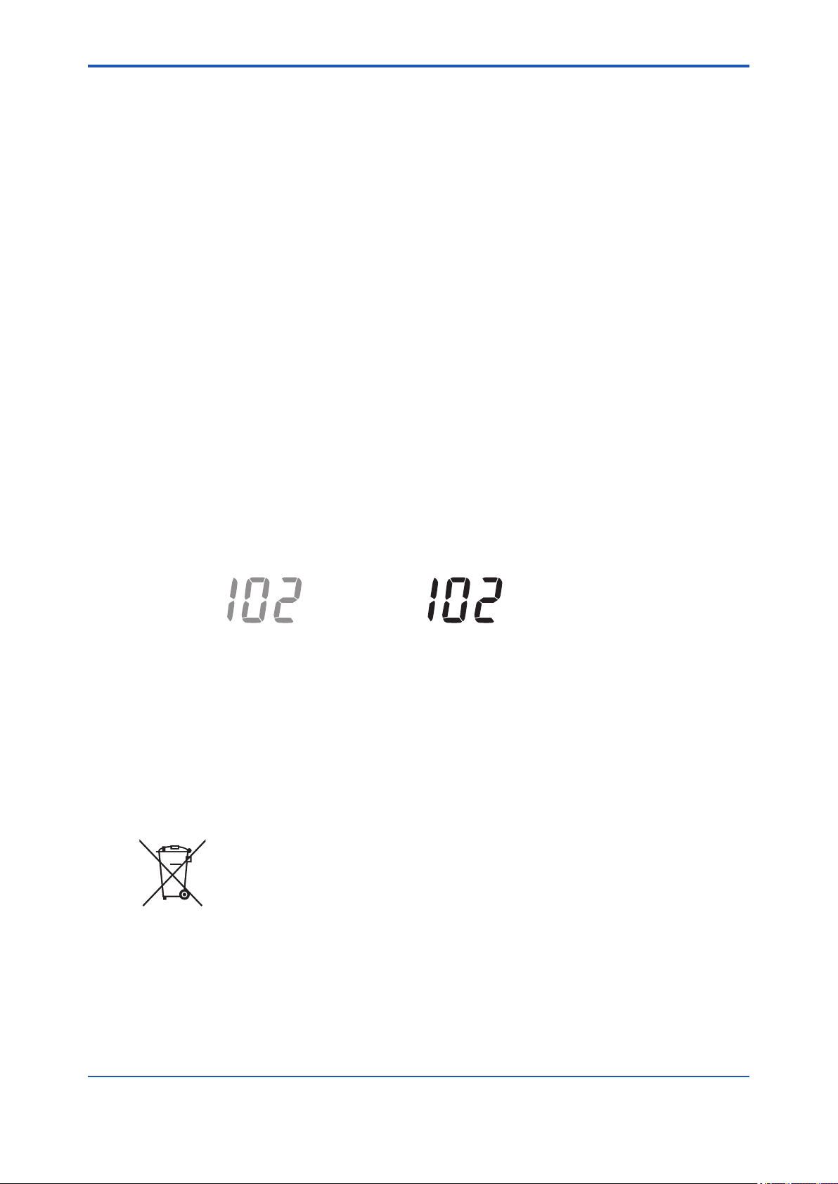
l Information on the State of Blinking
Indicated in shaded typography as:
, in contrast to (lit) (blinking)
[How to dispose the batteries]
This is an explanation about the new EU Battery Directive (DIRECTIVE 2006/66/EC). This direc-
tive is only valid in the EU.
Batteries are included in this product. Batteries incorporated into this product cannot be removed
by yourself. Dispose them together with this product.
When you dispose this product in the EU, contact your local Yokogawa Europe B.V.ofce. Do not
dispose them as domestic household waste.
Battery type: silver oxide battery
Notice : The symbol (see above) means they shall be sorted out and collected as ordained in ANNEX II in DIRECTIVE 2006/66/EC.
IM 11T3E1-01E
Page 5

<Introduction>
u After-sales Warranty
n Do not modify the product.
n During the warranty period, for repair under warranty carry or send the prod-
uct to the local sales representative or service ofce. Yokogawa will replace
or repair any damaged parts and return the product to you. Before returning a
product for repair under warranty, provide us with the model name and serial
number and a description of the problem. Any diagrams or data explaining the
problem would also be appreciated.
l If we replace the product with a new one, we won’t provide you with a repair report.
l Yokogawa warrants the product for the period stated in the pre-purchase quotation
Yokogawa shall conduct dened warranty service based on its standard. When the customer site is located outside of the service area, a fee for dispatching the maintenance engineer
will be charged to the customer.
n In the following cases, customer will be charged repair fee regardless of war-
ranty period.
iv
• Failure of components which are out of scope of warranty stated in instruction manual.
• Failure caused by usage of software, hardware or auxiliary equipment, which Yokogawa
Electric did not supply.
• Failure due to improper or insufcient maintenance by user.
• Failure due to modication, misuse or outside-of-specications operation which Yokogawa
does not authorize.
• Failure due to power supply (voltage, frequency) being outside specications or abnormal.
• Failure caused by any usage out of scope of recommended usage.
• Any damage from re, earthquake, storms and oods, lightning, disturbances, riots, warfare,
radiation and other natural changes.
n Yokogawa does not warrant conformance with the specic application at the
user site. Yokogawa will not bear direct/indirect responsibility for damage due
to a specic application.
n Yokogawa Electric will not bear responsibility when the user congures the
product into systems or resells the product.
n Maintenance service and supplying repair parts will be covered for ve years
after the production ends. For repair for this product, please contact the nearest sales ofce described in this instruction manual.
IM 11T3E1-01E
Page 6

<CONTENTS>
Model GD402
Gas Density Meter
IM 11T3E1-01E 7th Edition
CONTENTS
Introduction ..............................................................................................................i
u After-sales Warranty ...................................................................................................... iv
1. SPECIFICATIONS ..................................................................................... 1-1
1.1 Specications ....................................................................................................1-1
1.1.1 General Specications .......................................................................1-1
1.1.2 GD40G, T, V, R Detector ....................................................................1-5
1.1.3 GD402G, T, V, R Converter................................................................ 1-5
1.2 Model and Sufx Codes ...................................................................................1-7
1.2.1 Gas Density Converter ......................................................................1-7
1.2.2 Gas Density Detector .........................................................................1-7
1.2.3 Hardware for Connection with External Cables
(For Explosion-proof use) ..................................................................1-8
1.2.4 Two-core, Double-Shielded Cable ..................................................... 1-8
1.2.5 Brain Terminal (Optional) ................................................................... 1-9
1.2.6 Pressure transmitter (Optional)..........................................................1-9
1.3 External Views and Dimension ......................................................................1-10
1.3.1 GD402G Converter (General purpose) ...........................................1-10
1.3.2 Pipe- and Wall-Mounting Hardware (Optional) ................................ 1-11
1.3.3. GD402T, V, R Converter (Explosion-proof) .....................................1-12
1.3.4 GD40 Detector .................................................................................1-13
1.3.5 Detector Unit (Intrinsically Safe, Explosion-proof) ...........................1-14
1.3.6 Surge protector: K9215LP ...............................................................1-14
Toc-1
2. INSTALLATION, WIRING AND PIPING .................................................... 2-1
2.1 Installing the Detector ......................................................................................2-1
2.1.1 Selecting the Location ........................................................................ 2-1
2.1.2 GD40T (FM Explosion-proof and Intrinsically Safe Approval) ...........2-2
2.1.3 GD40V (CSA Explosion-proof and Intrinsically Safe Approval) ........2-3
2.1.4 Mounting the Detector........................................................................2-4
2.2 Installing the Converter ....................................................................................2-5
2.2.1 Selecting the Location ........................................................................ 2-5
2.2.2 GD402T (FM Explosion-proof Approval) ...........................................2-6
2.2.3 GD402V (CSA Explosion-proof Approval) .........................................2-7
2.2.4 Mounting the Converter .....................................................................2-8
IM 11T3E1-01E
Page 7

<CONTENTS>
2.3 Piping ...............................................................................................................2-10
2.4 Wiring ...............................................................................................................2-12
2.4.1 Wiring Procedure .............................................................................2-12
2.4.2 Cables Wired to Power Supply ........................................................2-16
2.4.3 Cables Wired to Outputs ..................................................................2-17
2.4.4 Cables Wired to Contact I/Os ..........................................................2-18
2.4.5 Cable Wired to GD40 Detector .....................................................2-19
2.4.6 Cables Wired to the Ground ............................................................2-20
3. OPERATION .............................................................................................. 3-1
3.1 Preparation for Operation ................................................................................3-1
3.1.1 Inspecting Installation, Piping and Wiring Workmanship .................. 3-1
3.1.2 Supplying Power ................................................................................ 3-2
3.1.3 Display on Operation Panel and Operation Keys ..............................3-3
3.1.4 Basic Key Operation ..........................................................................3-4
3.1.5 Checking the Setting Parameters .....................................................3-6
3.1.6 Calibrating the Analyzer for Correct Readings ..................................3-6
3.1.7 Checking the Analyzer for Performance ............................................3-7
3.2 Normal Operation .............................................................................................. 3-8
3.2.1 Starting Operation ..............................................................................3-8
3.2.2 Corrective Actions in Case of Failure ................................................. 3-8
3.2.3 Inspection and Maintenance ..............................................................3-9
3.3 Shutdown and Restart ......................................................................................3-9
3.3.1 Measures for Shutdown .....................................................................3-9
3.3.2 Measures for Restarting ....................................................................3-9
Toc-2
4. FUNCTIONS .............................................................................................. 4-1
4.1 Summary of Setting Operations ...................................................................... 4-1
4.1.1 Measurement, Operation, Setting and Service .................................4-1
4.1.2 Key Operations ..................................................................................4-1
4.1.3 Points to Be Noted When Making Settings ........................................4-2
4.2 Setting Lists .......................................................................................................4-2
5. DENSITY / PARAMETER SETTING ......................................................... 5-1
5.1 Setting Parameters ...........................................................................................5-2
5.1.1 Setting Parameters at Measurement Level .......................................5-2
5.1.2 Setting Parameters at Operation Level ............................................. 5-3
5.1.3 Setting Parameters at Setting Level ..................................................5-4
5.1.4 Setting Parameters at Service Level .................................................5-5
5.2 Parameter Setting .............................................................................................5-6
5.2.1 Parameter Setting at Operation Level ...............................................5-6
5.2.2 Parameter Setting at Setting Level ..................................................5-10
5.2.3 Parameter Setting at Service Level .................................................5-16
6. CALORIE / PARAMETER SETTING ........................................................ 6-1
6.1 Setting Parameters ...........................................................................................6-2
IM 11T3E1-01E
Page 8

<CONTENTS>
6.1.1 Setting Parameters at Measurement Level .......................................6-2
6.1.2 Setting Parameters at Operation Level ............................................. 6-3
6.1.3 Setting Parameters at Setting Level ..................................................6-4
6.1.4 Setting Parameters at Service Level .................................................6-5
6.2 Parameter Setting .............................................................................................6-7
6.2.1 Parameter Setting at Operation Level ...............................................6-7
6.2.2 Parameter Setting at Setting Level ..................................................6-12
6.2.3 Parameter Setting at Service Level .................................................6-16
7. HYDROGEN PURITY/PARAMETER SETTING ....................................... 7-1
7.1 Setting Parameters ...........................................................................................7-2
7.1.1 Setting Parameters at Measurement Level .......................................7-2
7.1.2 Setting Parameters at Operation Level ............................................. 7-2
7.1.3 Setting Parameters at Setting Level ..................................................7-3
7.1.4 Setting Parameters at Service Level .................................................7-4
7.2 Parameter Setting .............................................................................................7-6
7.2.1 Parameter Setting at Measurement Level ......................................... 7-6
7.2.2 Parameter Setting at Operation Level ...............................................7-7
7.2.3 Parameter Setting at Setting Level ..................................................7-10
7.2.4 Parameter Setting at Service Level .................................................7-14
Toc-3
8. DENSITY /CALIBRATION PROCEDURE ................................................ 8-1
8.1 Basic Calibration Procedure ............................................................................8-1
8.2 Preparation for Calibration ..............................................................................8-1
8.2.1 Setting Type of Calibration and Checking Valve Operation ...............8-1
8.2.2 Setting Calibration Data ..................................................................... 8-3
8.3 Calibration .........................................................................................................8-4
8.3.1 Semi-automatic Calibration ............................................................... 8-4
8.3.2 Manual Calibration .............................................................................8-5
8.3.3 Automatic Calibration .........................................................................8-6
9. CALORIE /CALIBRATION PROCEDURE ................................................ 9-1
9.1 Basic Calibration Procedure ............................................................................9-1
9.2 Preparation for Calibration ..............................................................................9-1
9.2.1 Setting Type of Calibration and Checking Valve Operation ...............9-1
9.2.2 Setting Calibration Data ..................................................................... 9-3
9.3 Calibration .........................................................................................................9-5
9.3.1 Semi-automatic Calibration ............................................................... 9-5
9.3.2 Manual Calibration .............................................................................9-6
9.3.3 Automatic Calibration .........................................................................9-7
10. HYDROGEN PURITY /CALIBRATION PROCEDURE .......................... 10-1
10.1 Basic Calibration Procedure ..........................................................................10-1
10.2 Preparation for Calibration ............................................................................10-1
10.3 Calibration .......................................................................................................10-2
IM 11T3E1-01E
Page 9

<CONTENTS>
11. INSPECTION AND MAINTENANCE ...................................................... 11-1
11.1 Routine Inspection and Maintenance ........................................................... 11-1
11.1.1 Checking Readings and Calibrating the Analyzer ........................... 11-1
11.1.2 Checking the Flowrate of Sample Gas ............................................ 11-1
11.1.3 Periodic Replacement of the Detector's O-rings ............................. 11-1
11.1.4 Replacing the Fuse .......................................................................... 11-2
11.1.5 Cleaning ........................................................................................... 11-2
11.2 Inspection In Case of Failure ......................................................................... 11-3
11.2.1 Inspecting the Analyzer in an Alarm Status ..................................... 11-3
11.2.2 Inspecting the Analyzer in a FAIL Status ......................................... 11-4
Customer Maintenance Parts List ...........................................CMPL 11T3E1-01E
Customer Maintenance Parts List ...........................................CMPL 11T3E1-02E
Customer Maintenance Parts List ...........................................CMPL 11T3E1-03E
Revision Information ...............................................................................................i
Toc-4
IM 11T3E1-01E
Page 10

<1. Specications>
1. SPECIFICATIONS
1.1 Specications
The specications of the GD402 gas density meter as described below.
Certicate is approved for model GD402G, GD40G.
1.1.1 General Specications
l System Components
(1) GD40G, T, V, R Detector:Rainproof for outdoor use (equivalent to IP65/NEMA4X)
(see note under “1.1.2 Ambient conditions” on page1-5.)
Ambient Temperature : -10 to 60°C
Ambient Humidity : 5 to 95%RH
GD40G : General purpose detector.
1-1
(Non Explosion-proof)
Electrical connection : 1/2 NPT female
Process connection : 1/4 NPT female
GD40T : FM Explosion-proof and Intrinsically safe Approval.
Explosion-proof for Class I, Division 1, Groups B, C and D;
Dust Ignition-proof for Class II, III, Division 1, Groups E, F and G with Intrinsically
Safe sensor for Class I, II, III, Division 1, Groups B, C, D, E, F and G.
Enclosure : NEMA Type 4X
Temperature Code : T5
Electrical connection : 1/2 NPT female
Process connection : 1/4 NPT female
GD40V : CSA Explosion-proof and Intrinsically safe Approval.
Explosion-proof for Class I, Division 1, Groups B, C and D;
Dust Ignition-proof for Class II, III, Division 1, Groups E, F and G with Intrinsically
Safe sensor for Class I, II, III, Division 1, Groups B, C, D, E, F and G.
Enclosure : Type 4X
Temperature Code : T5
Electrical connection : 1/2 NPT female
Process connection : 1/4 NPT female
GD40R : TIIS Explosion-proof and Intrinsically safe Approval.
Explosion-proof code : Exd [ia] IIB+H2T5
Temperature Code : T5
Electrical connection : G1/2 female
Process connection : Rc1/4
IM 11T3E1-01E
Page 11

<1. Specications>
(2) GD402G, T, V, R Converter : Rainproof for outdoor use (equivalent to IP65 / NEMA 4X)
Ambient Temperature : -10 to 55°C
Ambient Humidity : 5 to 95%RH
GD402G : General purpose converter. (Non Explosion-proof).
Electrical connection : 21mm (0.9inch) in diameter. Pg 13.5 cable glands includ-
ed
GD402T : FM Explosion-proof Approval.
Explosion-proof for Class I, Division 1, Groups B, C and D;
Dust Ignition-proof for Class II, III, Division 1, Groups E, F and G.
Enclosure : NEMA Type 4X
Temperature Code : T6
Electrical connection : 1/2 NPT female
GD402V : CSA Explosion-proof Approval.
Explosion-proof for Class I, Division 1, Groups B, C and D;
Dust Ignition-proof for Class II, III, Division 1, Groups E, F and G.
1-2
Enclosure : Type 4X
Temperature Code : T6
Electrical connection : 1/2 NPT female
GD402R : TIIS Explosion-proof Approval.
Explosion-proof code : Exd IIB+H2T6
Temperature Code : T6
Electrical connection : G3/4 female
(3) EJA310 Absolute pressure transmitter (optional)
FM Explosion-proof Approval:
Explosion-proof for Class I, Division 1, Groups B, C and D;
Dust Ignition-proof for Class II, III, Division 1, Groups E, F and G.
Hazardous(classied locations, indoors and outdoors (NEMA 4X)
Temperature Code : T6
Ambient Temperature : -40 to 60°C
Ambient Humidity : 5 to 100%RH (at 40°C)
Electrical connection : 1/2 NPT female
Process connection : 1/4 NPT female
CSA Explosion-proof Approval:
Explosion-proof for Class I, Division 1, Groups B, C and D;
Dust Ignition-proof for Class II, III, Division 1, Groups E, F and G.
Division2 ‘SEALS NOT REQUIRED’
Enclosure : Type 4X
Temperature Code : T4, T5, T6
Max. Process Temp.: T4 120°C, T5 100°C, T6 85°C
Ambient Temperature : -40 to 80°C
IM 11T3E1-01E
Page 12

<1. Specications>
Ambient Humidity : 5 to 100%RH (at 40°C)
Electrical connection : 1/2 NPT female
Process connection : 1/4 NPT female
TIIS Explosion-proof Approval:
Explosion-proof code : Ex do IIC T4X
Temperature Code : T4
Ambient Temperature : -20 to 60 °C
Ambient Humidity : 5 to 100%RH (at 40°C)
Electrical connection : G1/2 female
Process connection : Rc1/4
l Sample Gas conditions
Sample gas: All gases except for corrosive gas and acetylene gas.
Temperature: -10 to 50 °C (non-condensing)
Pressure: Max. 588.5 kPa (abs)
Gas ow: 0.1 to 1 l/min
1-3
l Output Signals
Output 1: 4-20 mA DC
Isolated from inputs; load resistance: 600 W maximum (Load resistance of 250-
550 W required when in the BRAIN communication mode.)
Output 2: 4-20 mA DC
Isolated from inputs; load resistance: 600 W maximum
l Power Supply
Rated voltage range: 100 to 240 V AC, 24 V DC
Allowable voltage range: 85 to 264 V AC, 21.6 to 26.4 V DC
Rated frequency: 50 or 60 Hz
Allowable frequency range: 47 to 63 Hz
l Power Consumption
Approximately 12 W.
l Safety and EMC Compliance
Safety Standards: EN61010-1
EMC Standards:
(Applied only when GD402G converter is used with GD40G detector.)
Emission: EN61326 Class A
EN61000-3-2
EN61000-3-3
AS/NZS CISPR11
Immunity: EN61326 Annex A and F
KC Marking: Korea Electromagnetic Conformity Standard
IM 11T3E1-01E
Page 13
<1. Specications>
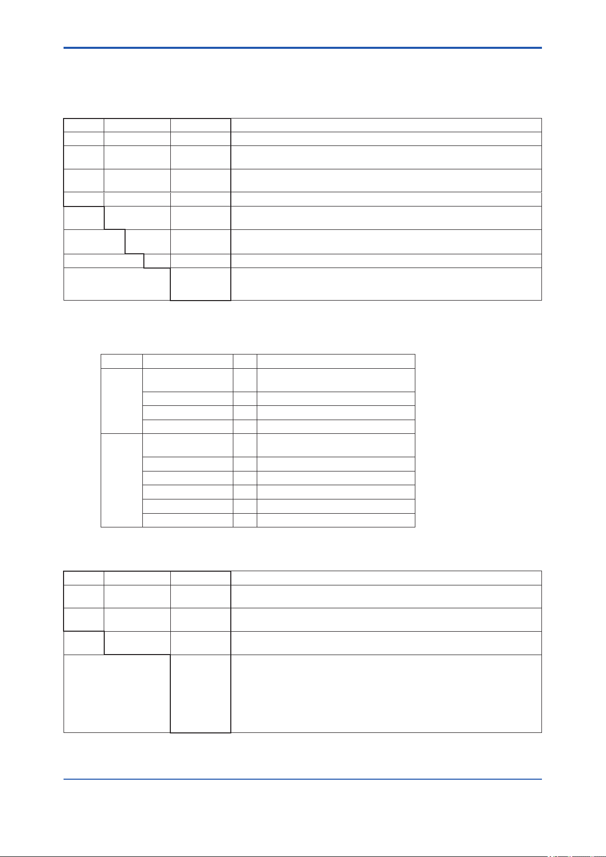
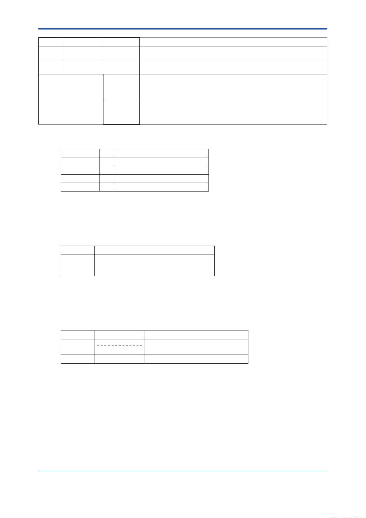
l Characteristics
GD402 specication list
Item Density kg/m3 Density lb/ft3 Specic Gravity Molecular Weight Concentration vol%
Range
0 - 6 (compensated)
0 - 60 (physical)
Minimum Range 0.1 0.01 0.1 4
Response Time 90% approx. 5 sec approx. 5 sec approx. 5 sec approx. 5 sec approx. 5 sec
Linearity +/-1 % FS +/-1 % FS +/-1 % FS +/-1 % FS +/- 1
Repeatability
+/- 0.001
or +/-0.5%FS *
Long term stability +/- 0.003/month +/- 0.002/month +/- 0.003/month +/- 0.07/month
*: Whichever is greater
Density is the basic measurement, the other representations are derived from the Density data.
Item H2 in Air vol% H2 in CO2 vol% Air in CO2 vol% Caloric value MJ/m
Range 85 - 100 0 - 100 0 - 100 0 - 130 0 - 3.5
Minimum
Range
Response
Time 90%
Linearity +/- 1 +/- 1 +/- 1 +/- 1 % FS +/- 1 % FS
Repeatability +/- 0.5 +/- 0.5 +/- 0.5 +/- 0.5%FS or Caloric value
Drift +/- 0.5/month +/- 0.5/month +/- 0.5/month Caloric value equivalent to
– – –
approx. 5 sec approx. 5 sec approx. 5 sec approx. 5 sec approx. 5 sec
0 - 0.4 (compensated)
0 - 4 (physical)
+/- 0.0001
or +/-0.5%FS*
0 - 5 0 - 140 0 - 100
Concentration equivalent
to 100 kg/m3
+/- 0.001
or +/-0.5%FS*
+/- 0.02
or +/-0.5%FS*
+/- 0.5% or Concentration
equivalent to
+/-0.001kg/m3 *
Concentration equivalent
to +/- 0.003 kg/m3/month
3
British Thermal Unit KBTU/ft
Caloric value equivalent to
0.100 kg/m
3
Caloric value equivalent to
0.100 kg/m
+/- 0.5%FS or Caloric value
equivalent to 0.001kg/m3*
equivalent to 0.001kg/m3 *
Caloric value equivalent to
+/- 0.003kg/m3 /month
+/- 0.0025/month
3
1-4
3
Caloric Value and BTU are possible representations of the Density.
GD402 does not contain table information, only a single mathematical equation.
*: Whichever is greater
IM 11T3E1-01E
Page 14

<1. Specications>
1.1.2 GD40G, T, V, R Detector
l Material exposed to gas
SUS 316 stainless steel, Acrylonitrile Butadiene Rubber and Fluorine-contained Rubber
(O-ring)
l Ambient conditions
Temperature: -10 to 60 °C (14 to 140 °F)
Humidity: 5 to 95 %RH
Installation: Pipe-mounted or on panel
Construction: Explosion-proof and Intrinsically safe. (See 1.1.1 “System Components”)
Though the detector construction makes it relatively insensitive to sudden changes in
the gas temperature, extra precision can be achieved by keeping ambient temperature conditions as constant as possible. In measurements where optimum precision is
required it is therefore not recommended to install the detector in an outdoors environment, especially not if such installation is prone to direct sunlight.
l Finish
Cover: Equivalent to Munsell 0.6GY3.1/2.0
1-5
Case: Equivalent to Munsell 2.5Y8.4/1.2
l Weight
Approximately 7 kg (with pipe mounting bracket)
l Detector unit
When the system is ordered to be used as a hydrogen purity meter, an optional pressure
transmitter is required for pressure compensation.
• If /EJAJ1, /EJAF2, /EJAF3 or, /EJAF4 are ordered, the detector unit and the
pressure transmitter and the tubing in between will all be integrated on a single mounting
plate. This allows the space where the pressure transmitter is normally mounted to be used
effectively for other purposes.
1.1.3 GD402G, T, V, R Converter
l Display
Reading: Digital (6 digits maximum; resolution: 0.0001 kg/m3)
Data items shown:
Measured value: Always on display.
Alarm indications: Abnormal concentration, abnormal pressure range of input and abnormal
value of calibration.
Parameters for calibration: Time of calibration, settling time, starting time of calibration and
calibration cycle
Self-diagnostic indications: Sensor oscillation shutdown, abnormal oscillation frequency of
sensor, failure in sensor temperature detection, failure in A/D conversion
stage and memory failure.
Alarm settings: The contact state can be set to either “normally open (NO)” or “normally
closed (NC)” depending on the needs of the application.
Temperature: Temperature of gas being measured
IM 11T3E1-01E
Page 15

<1. Specications>
l Contact Outputs/Input
Contact output: Signals for Maintenance, Fail, Hi/Lo alarms
Contact capacity: 250 V AC at 3 A or 30 V DC at 3 A
Contact input: Signal for switching between the Hydrogen Purity meter and the Replace-
ment meter
l Calibration
Manual (one touch), Semi automatic, Automatic calibration
l Communication
Protocol: BRAIN communication
Data items that can be transmitted by the hand-held terminal are
numerical data, such as concentration, temperature and pressure,
alarm setpoint and self-diagnostic parameters.
l Ambient Conditions
Temperature: -10 to 55 °C (14 to 131°F)
Humidity: 5 to 95 %RH
l Installation
1-6
Non-explosion-proof models: Pipe-, panel- or wall-mounted
Explosion-proof models: Pipe- or panel-mounted
l Finish
GD402G (general purpose):
Front cover: Equivalent to Munsell 0.6GY3.1/2.0
Case: Equivalent to Munsell 2.5Y8.4/1.2
GD402T, V, R (explosion-proof):
Equivalent to Munsell 0.6GY3.1/2.0
l Weight
GD402G (general purpose): Approx. 3 kg (including mounting hardware)
GD402T, V, R (explosion-proof): Approx. 15 kg (including mounting hardware)
l Fuse
250 V 1 A quick acting type authorized VDE/SEMKO 100 to 240 V AC Model
250 V 2 A quick acting type authorized VDE/SEMKO 24 V DC Model
IM 11T3E1-01E
Page 16
<1. Specications>
1.2 Model and Sufx Codes
1.2.1 Gas Density Converter
Model Sufx code Option code Description
GD402G - - - - - - - - - - - - - - - - - - - - - - - - - General purpose model, 6 cable glands included.
GD402T - - - - - - - - - - - - - - - - - - - - - - - - - FM certied explosion - proof model. Gland threads 1/2 NPT. No cable glands
GD402V - - - - - - - - - - - - - - - - - - - - - - - - - CSA certied explosion - proof model. Gland threads 1/2 NPT. No cable glands
GD402R - - - - - - - - - - - - - - - - - - - - - - - - - TIIS certied explosion - proof model. Gland threads G3/4. No cable glands included.
Power
supply-D-A
Label and
approval
Instruction Manual -E - - - - - - - - - - - - English
Options
(only GD402G)
Note: Explosion -proof models, GD402T, V, R have only pipe mounting hardware as standard.
-E
-J
- - - - - - - - - - - -
- - - - - - - - - - - -
- - - - - - - - - - - -
- - - - - - - - - - - -
/PA
/U
/H
included.
included.
24 V DC
100-240 V AC
English label
TIIS approval, English label (only GD402R)
Panel mounting
Universal (Pipe and Wall) Mounting
Mood
1-7
GD402 Standard Accessory List
Model Item Qty Part Number
GD402G
GD402R
GD402T
GD402V
Fuse 1 A1109EF (Power Supply: 100-240 V AC)
Universal Mount Set 1 K9171SS
Panel Mount Set 1 K9171ST
Surge Protector 1 K9215LP
Fuse 1 A1109EF (Power Supply: 100-240 V AC)
Blacket 1 K9214HD
Blacket 1 K9214HE
U-Bolt Assy 2 D0177XL-A
Bolt 1 Y9835NU
Bolt 2 Y9820NU
A1111EF (Power Supply: 24 V DC)
A1111EF (Power Supply: 24 V DC)
1.2.2 Gas Density Detector
Model Sufx code Option code Description
GD40G - - - - - - - - - - - - - - - - - - - - - - - - - General purpose detector. 1/4 NPT gas threads and 1/2 NPT gland threads. No cable
GD40R - - - - - - - - - - - - - - - - - - - - - - - - - TIIS certied explosion - proof detector. Rc1/4 gas threads and G1/2 gland threads.
Label
approval-E-J
Options /EJAJ1
- - - - - - - - - - - -
- - - - - - - - - - - -
/EJAJ1T
/EJAF2
/EJAF2T
gland included. Mounting hardware included.
Cable gland included. Mounting hardware included.
English label, no approval (only GD40G)
TIIS approval, English label (only GD40R)
TIIS certied EJA mounted with detector on mounting plate. Rc1/4 gas threads and
G1/2 gland thread. Cable gland included.(only GD40R)
TIIS certied EJA mounted with detector on mounting plate. Rc1/4 gas threads and
G1/2 gland thread. Cable gland included. EJA with TAG (only GD40R)
EJA mounted with detector on mounting plate.1/4 NPT gas threads and 1/2 NPT gland
threads. No cable gland included.(only GD40G)
EJA mounted with detector on mounting plate.1/4 NPT gas threads and 1/2 NPT gland
threads. No cable gland included. EJA with TAG (only GD40G)
IM 11T3E1-01E
Page 17
<1. Specications>
Model Sufx code Option code Description
GD40T - - - - - - - - - - - - - - - - - - - - - - - - - FM certied explosion - proof detector. 1/4 NPT gas threads and 1/2 NPT gland thread.
GD40V - - - - - - - - - - - - - - - - - - - - - - - - - CSA certied explosion - proof detector. 1/4 NPT gas threads and 1/2 NPT gland
Options /EJAF3
/EJAF3T
/EJAF4
/EJAF4T
No cable gland included. Mounting hardware included
thread. No cable gland included. Mounting hardware included.
FM certied EJA mounted with detector on mounting plate.1/4 NPT gas threads and
1/2 NPT gland thread. No cable gland included. (only GD40T)
FM certied EJA mounted with detector on mounting plate.1/4 NPT gas threads and
1/2 NPT gland thread. No cable gland included. EJA with TAG (only GD40T)
CSA certied EJA mounted with detector on mounting plate. 1/4 NPT gas threads and
1/2 NPT gland thread. No cable gland included. (only GD40V)
CSA certied EJA mounted with detector on mounting plate. 1/4 NPT gas threads and
1/2NPT gland thread. No cable gland included. EJA with TAG (only GD40V)
GD40 Standard Accessory
Item Qty Part Number
U-Bolt Assy*
Blacket*
Blacket*
Gland*
*1: Not supplied when option code “/EJAJ1”, “/EJAF2”, “/EJAF3” or “/EJAF4” is specied.
*2: Supplied only for GD40R.
1
4 D0177XL-A
1
1
2
1 K9214HD
1 K9214HE
1 G9601AM
1-8
1.2.3 Hardware for Connection with External Cables (For Explosion-proof use)
Part No. Description
L9811LL G3/4 explosion-proof cable gland.
Cable’s outside diameter 8 to 16 mm.
Used for the GD402R converter.
Note: Specify the number of cable glands for converter in hazardous area
1.2.4 Two-core, Double-Shielded Cable
Normally two conductor shielded cable can be used, but when failure arises from noises
disturbance, this cable is recommended for connection between the GD402 converter and
GD40 detector.
Model Basic code Description
GDW Two - core, double-shielded cable,
both ends nished with cable pins.
Length
-L
Length in meters, 500 meter maximum.
IM 11T3E1-01E
Page 18

<1. Specications>
1.2.5 Brain Terminal (Optional)
Model Sufx code Option code Description
BT200 - - - - - - - - - - - - - - - - - - - - - - - - - Brain terminal [Note]
Printer -N
-P
– 00 - - - - - - - - - - - - Always 00
Options
Note: The BT200 has following accessories, two communication cables, one with IC clips and another with alligator clips, handy
carrying case and ve AA 1.5 V dry batteries.
OPTIONS FOR BT200
Options Description Option codes
Communication cable
(Note 1)
Intrinsically safe type
(Note 1) (Note 2)
(Note 1) Optional code /C1 can not be combined with /CS1.
(Note 2) Applicable only for Model BT200-N00.
See GS 01C00A11-00EN for “BT200” brain terminal in detail.
- - - - - - - - - - - -
- - - - - - - - - - - -
/
With a 5-pin connector
(for the signal conditioner)
CSA Intrinsically safe approval
Class I, Groups A, B, C and D Temp. Code : T4
Standard type (without printer)
With printer
/C1
/CS1
1-9
1.2.6 Pressure transmitter (Optional)
/EJAJ1 means TIIS certied EJA310.
/EJAF2 means general purpose model EJA310.
/EJAF3 means FM certied EJA310.
/EJAF4 means CSA certied EJA310.
See GS 01C22D01-00E for “EJA310” pressure transmitter in detail if a different
selection from pre-selected options seems necessary.
IM 11T3E1-01E
Page 19
<1. Specications>
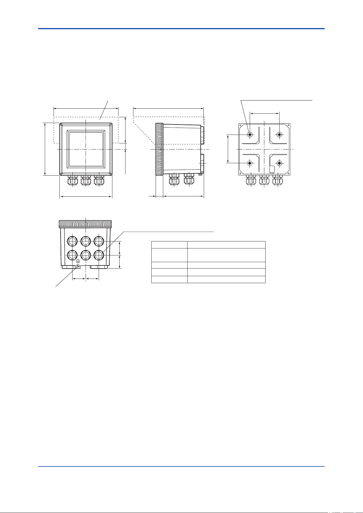
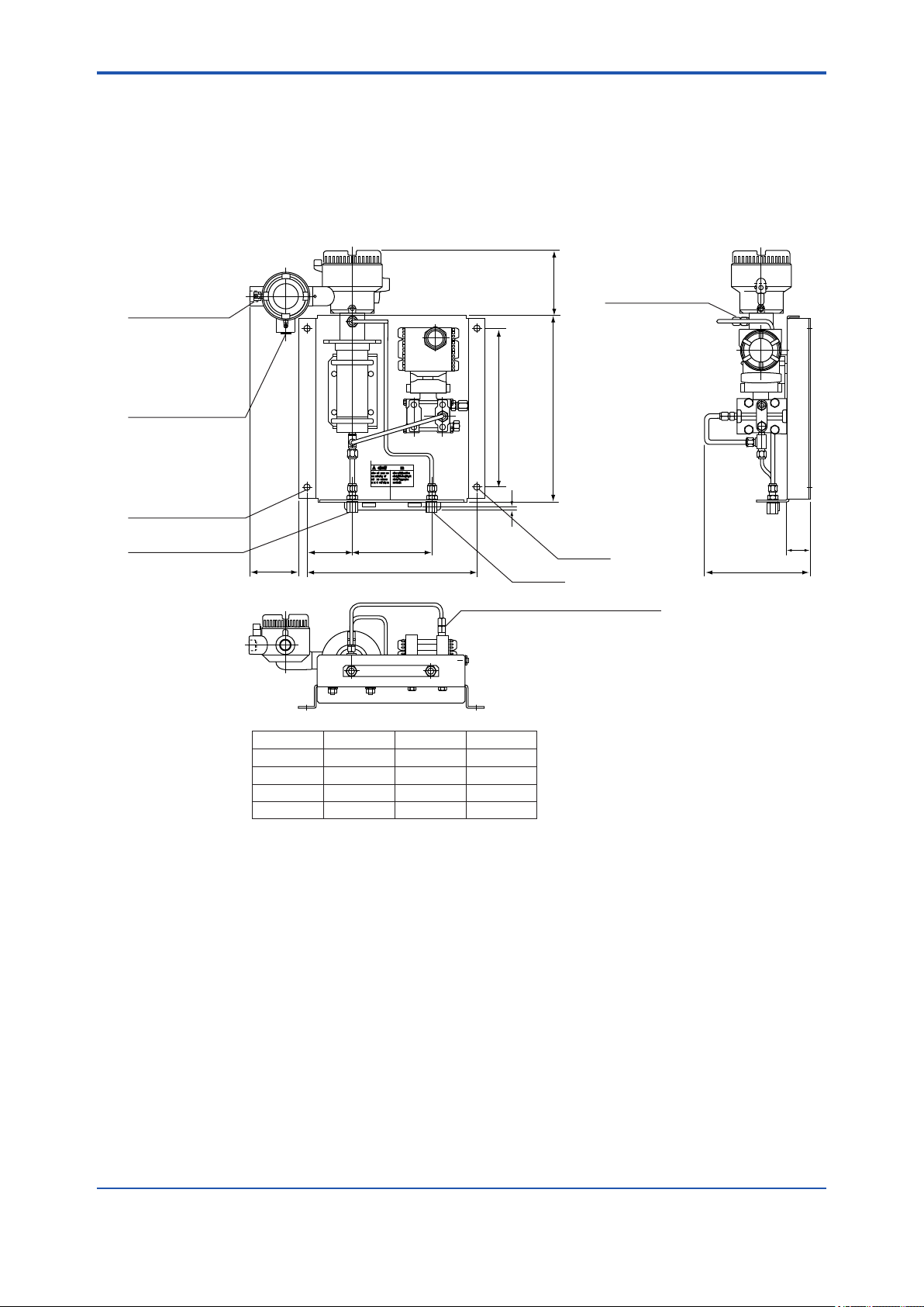
1.3 External Views and Dimension
1.3.1 GD402G Converter (General purpose)
1-10
Unit: mm(in.)
184 (7.2)
144(5.7)
144 (5.7)
A B
D F
36 36
Grounding terminal (4 mm screws)
C
E
(1.4)(1.4)
Hood
(Option code: /H)
220 (8.7)
72 (2.8)
20 (0.8)
112 (4.4)
23
(0.9)
Cable inlet (21 mm in dia.)
Compatible with a PG 13.5 cable gland
Cable gland Connection
36
38
(1.4)
(1.5)
A, B
C
D, E
F
Four holes, 6 mm (0.24) in dia.,
8 mm deep M6
80 (3.1)
80 (3.1)
• Pressure transmitter
• Analog Output • Contact Input
• Detector
• Contact Output
• Power Supply
Weight : Approx. 3 kg (6.6 pounds)
(including mounting hardware)
F0101.ai
IM 11T3E1-01E
Page 20
<1. Specications>
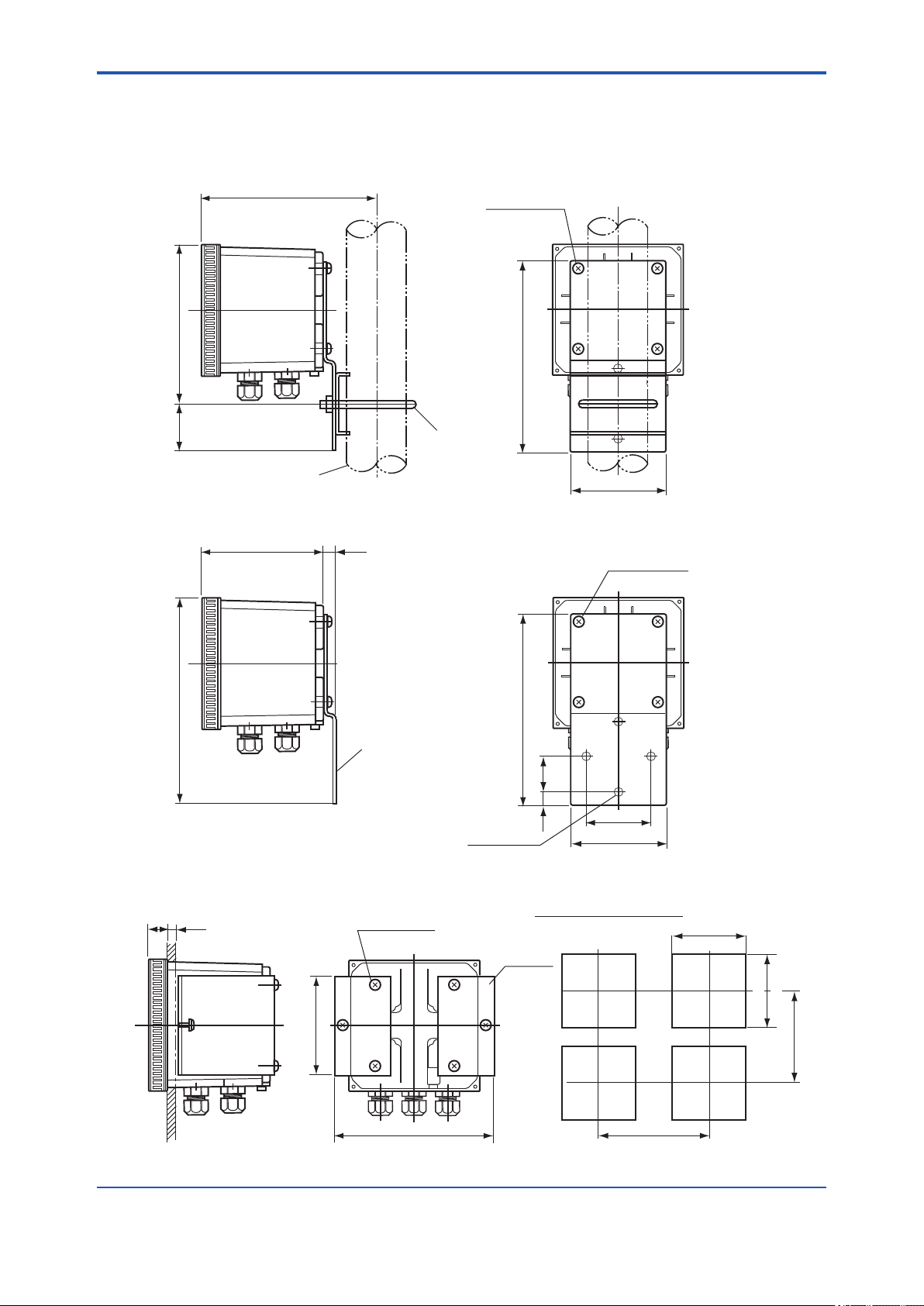
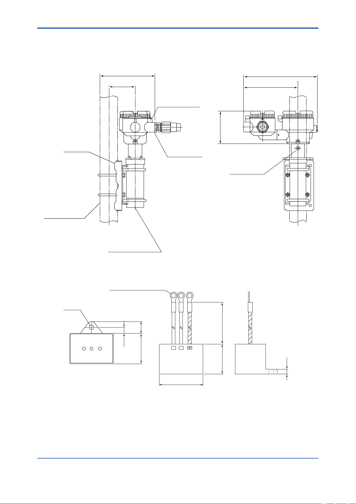
1.3.2 Pipe- and Wall-Mounting Hardware (Optional)
1-11
• Hardware for Pipe Mounting (Option code /U)
188 (7.4)
174 (6.9)
(2)
50
Mounting pipe of JIS 50 A (60.5 mm in outer dia.)
Optional
hardware
4 - M6 screws
• Hardware for Wall Mounting (Option code /U)
135 (5.3)
13
(0.51)
Unit : mm (in.)
Weight : Approx. 3 kg
200 (7.9)
100 (3.9)
4 - M6 screws
224 (8.8)
Optional
hardware
3-Ø10 holes
• Hardware for Panel Mounting (Option code /PA)
23
(0.9)
max. 12
(panel thickness)
100 (3.9)
4 - M6 screws
Optional
hardware
178 (7)
200 (7.9)
35
(1.4)
(0.6)
70 (2.8)
100 (3.9)
185 (7.3)
15
Dimensions of panel cutout
+1
139
0
+0.08
(5.47 )
0
139
+1
0+1 0
(5.47 )
F0102.ai
195 (7.7)
IM 11T3E1-01E
Page 21
<1. Specications>
1.3.3. GD402T, V, R Converter (Explosion-proof)
Weight : approx. 15 kg (33.1 pounds)
Pipe-mounting hardware
Mounting pipe of JIS 50 A nominal size (Φ60.5)
1-12
Unit : mm (in.)
Φ212 (8.3)
Side view from arrow A direction
Cable glands not included
4 - M8 depth 20
140 (5.5)
24 (0.9)
39
(1.5)
54
(2.1)
200 (7.9)
182 (7.2)
A
200 (7.9)
A B
D ECF
209 (8.2)
173 (6.8)
2 - M8 depth 16 (one on each side)
(Used to fix the pipe-mounting hardware)
36 (1.4)
242 (9.5)
Grounding terminal (M5)
56
56
(2.2)
(2.2)
Cable gland Connection
A • Power Supply
B, C • Contact Output
D • Detector
E, F
• Pressure Transmitter
• Analog Output • Contact Input
Six wiring holes, G3/4 threaded (GD402R)
1/2 NPT threaded (GD402V, T)
F0103.ai
IM 11T3E1-01E
Page 22
<1. Specications>
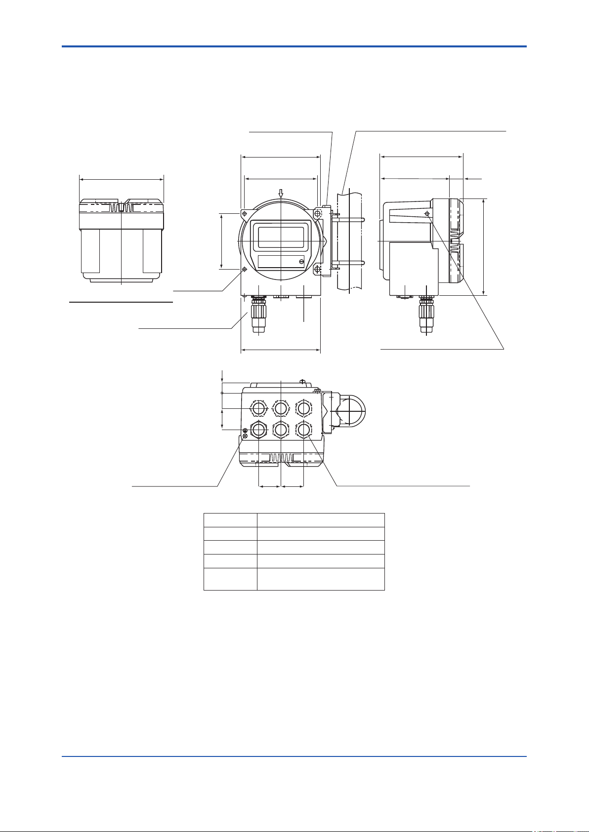
1.3.4 GD40 Detector
• Model GD40- /EJAJ1, /EJAF2, /EJAF3, /EJAF4
Weight: approx. 15 kg (27.8 pounds)
1-13
Unit: mm (in.)
GD40
Detector wiring port
See Table
Cable gland is included
only in EJAJ1
Four panel-mounting
holes, 12 mm in
diameter
Gas out
See Table
∆ abcdf m
abc cd nmv sc
abc vdfbjkosblm
xs xdcvbg vf
sbdgjklodenjhl;pk
ad xs cdnmn
nbdvf kggswba
z x d cdf vfg m
nscbxfk
150 (5.9)100 (3.9)
93 (3.7) 320 (12.6)
EJA wiring port
See Table
4-ø12 (0.47)
300 (11.8)
5
350 (13.8)
Gas in
See Table
120 (4.7)
Cable gland is included only in /EJAJ1
40
(1.6)
196 (7.7)
Option code GD40 wiring EJA wiring Gas out/in
/EJAJ1 G1/2 G1/2 Rc1/4
/EJAF2 1/2 NPT 1/2 NPT 1/4 NPT
/EJAF3 1/2 NPT 1/2 NPT 1/4 NPT
/EJAF4 1/2 NPT 1/2 NPT 1/4 NPT
F0104.ai
IM 11T3E1-01E
Page 23
<1. Specications>
1.3.5 Detector Unit (Intrinsically Safe, Explosion-proof)
• Hardware for Pipe Mounting : GD40
1-14
Unit: mm (in.)
Pipe-mounting
hardware
Mounting pipe
(JIS 50 A (60.5 mm in
outer dia.) nominal size)
Approx. 191 (7.5)
Approx. 92 (3.6)
Sample gas outlet
GD40R: Rc1/4
GD40V: 1/4 NPT
GD40T: 1/4 NPT
GD40G: 1/4 NPT
Grounding terminal
(3 mm (0.11) screw)
Wiring hole,
GD40R: G1/2
GD40V: 1/2 NPT
GD40T: 1/2 NPT
GD40G: 1/2 NPT
Approx. 264 (10.4)
Approx. 193 (7.6)
Approx. 117 (4.6)
Sample gas inlet
GD40R: Rc1/4
GD40V: 1/4 NPT
GD40T: 1/4 NPT
GD40G: 1/4 NPT
Note: Cable gland is included only in GD40R.
F0105.ai
1.3.6 Surge protector: K9215LP
M4 SCREW TERMINAL
Ø4.2
(0.17)
1128.5
(0.43)
5.5
(0.22)
(1.12)
21
41
(1.61)
20028
(7.86)
(1.1)
Unit: mm (in.)
4.5
F0106.ai
(0.18)
IM 11T3E1-01E
Page 24

<2. Installation, Wiring and Piping>
2-1
2. INSTALLATION, WIRING AND PIPING
The GD402 Gas Density Meter is thoroughly inspected at the factory and carefully packed to
ensure the equipment does not suffer any damage during transportation.
The package should also be handled with care when unpacking to prevent the equipment from
undergoing severe mechanical shock. After unpacking, visually check the equipment to ensure
that it is free from any damage.
Although the detector has no controls on it, it may need to be accessed for inspection or for other
reasons. Install the detector in a location as close as possible to where the gas is sampled and
where maintenance can be easily carried out. The converter has a display with controls on it;
thus, you should install it so that the keys are positioned directly in front of you when working.
Note that there must be a clearance of at least 400 mm at the back of the converter GD402G,
GD402T, GD402V and GD402R since cables are wired to the back by removing the screwed
rear cover.
2.1 Installing the Detector
The GD40 detector is an explosion-proof with intrinsically safe sensor instrument. Install the
detector in a location where the following conditions are satised.
2.1.1 Selecting the Location
l Explosion-proof construction
Before installing the detector in an explosion-hazardous area, ensure that the area conforms to
the explosion-proof code noted above.
l No corrosive gases
Corrosive gases are not desirable because they may damage the electrical components in the
detector.
l Slight mechanical vibration
Although the detector is vibration-resistant, vibration may loosen the connections of the external
wiring.
l No exposure to direct sunlight
Exposure to direct sunlight may raise the temperature in the detector to abnormal levels, and
should therefore be avoided. Note that such abnormal temperature levels can also result from
heat irradiated from high-temperature equipment around the detector.
l Humidity maintained between 5% and 95 %RH
Avoid choosing a location that is likely to be exposed to abnormally high or low humidity over a
prolonged period. It is recommended that the detector be used at a humidity between 25% and
85 % RH.
l No exposure to rain water
Even though the detector is rainproof, whenever possible install it where it is protected from water
splashes. The reasoning for this is that the detector cover may need to be removed for maintenance or for other reasons.
l Altitude of installation site is lower than 2,000 m.
IM 11T3E1-01E
Page 25
<2. Installation, Wiring and Piping>
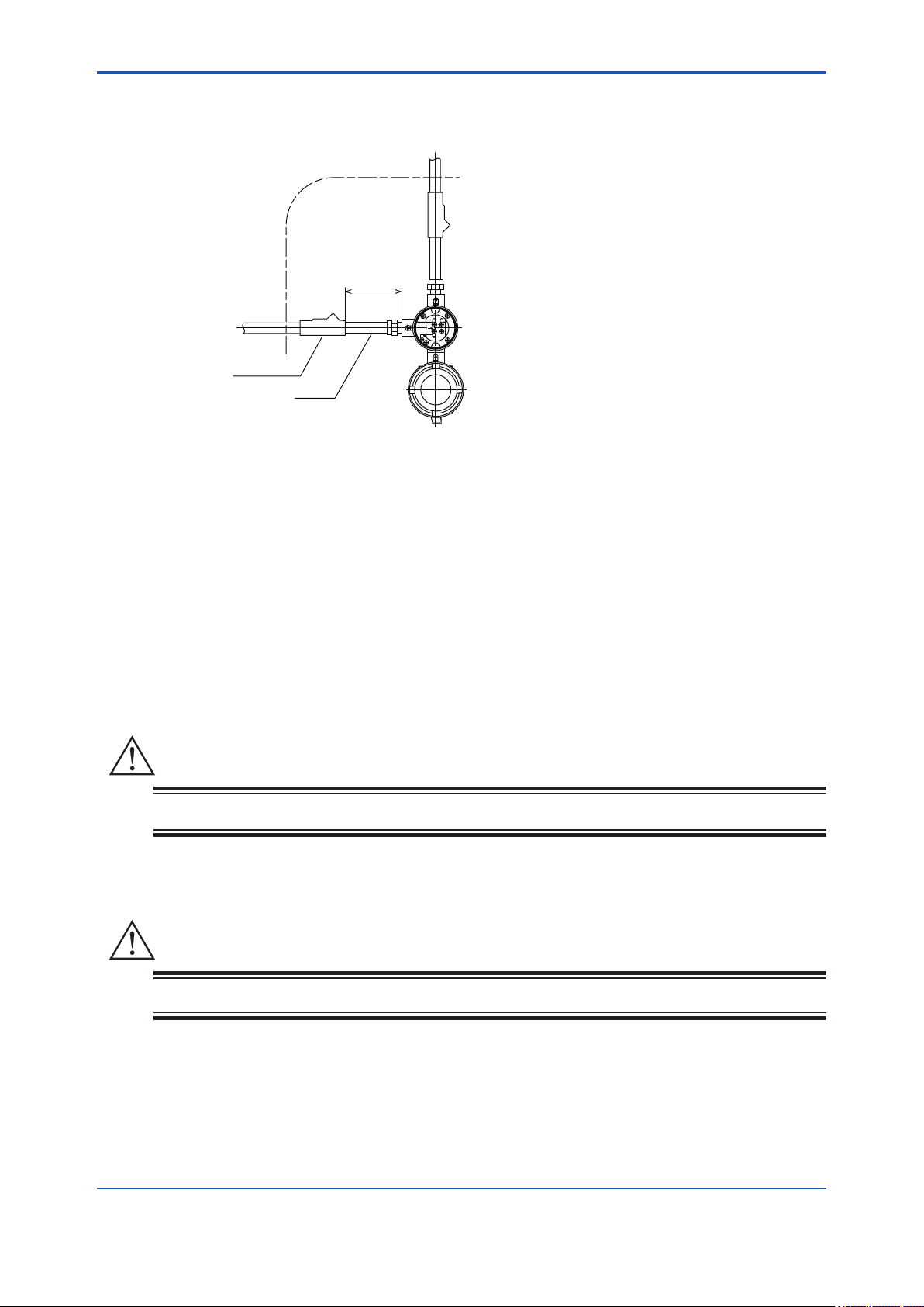
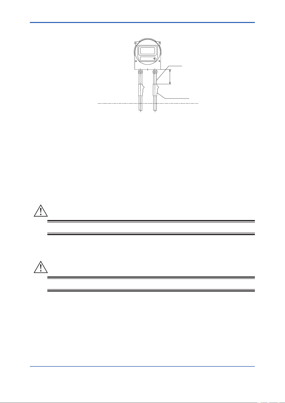
2.1.2 GD40T (FM Explosion-proof and Intrinsically Safe Approval)
2-2
NON-HAZARDOUS
LOCATIONS
Sealing Fitting
Figure 2.1
HAZARDOUS
LOCATIONS
475 mm (18") Max.
Conduit
GD40T
F0201.ai
1. GD40T Gas density detector for use in hazardous (classied) locations:
• Explosion-proof for Class I, Division 1, Groups B, C and D;
Dust Ignition-proof for Class II, III, Division 1, Groups E, F and G with Intrinsically
Safe sensor for Class I, II, III, Division 1, Groups B, C, D, E, F and G.
• Enclosure Rating: NEMA 4X
• Temperature Code: T5
• Ambient Temperature: -10 to 60°C
2. Wiring
• All wiring shall comply with National Electric Code ANSI/NAPA 70 and Local Electrical
Codes.
WARNING
Seal all conduits within 475 mm (18 inches). Refer to Figure 2.1.
3. Operation
• Note a warning label worded as follows.
WARNING
Open circuit before removing cover.
• Take care not to generate mechanical spark when access to the instrument and
peripheral devices in hazardous locations.
4. Maintenance and Repair
• The instrument modication or parts replacement by other than authorized representative
of Yokogawa Electric Corporation is prohibited and will void the approval of Factory
Mutual Research Corporation.
IM 11T3E1-01E
Page 26

<2. Installation, Wiring and Piping>
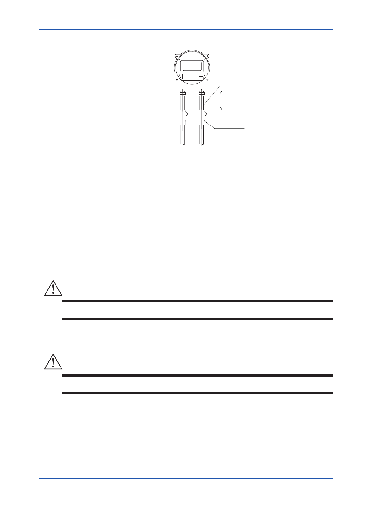
2.1.3 GD40V (CSA Explosion-proof and Intrinsically Safe Approval)
2-3
NON-HAZARDOUS
LOCATIONS
Sealing Fitting
Figure 2.2
HAZARDOUS
LOCATIONS
500 mm (20") Max.
Conduit
GD40V
F0203.ai
1. GD40V Gas density detector for use in hazardous (classied) locations:
• Explosion-proof for Class I, Division 1, Groups B, C and D;
Dust Ignition-proof for Class II, III, Division 1, Groups E, F and G with Intrinsically
Safe sensor for Class I, II, III, Division 1, Groups B, C, D, E, F and G.
• Enclosure Rating: Type 4X
• Temperature Code: T5
• Ambient Temperature: -10 to 60°C
2. Wiring
• All wiring shall comply with Canadian Electrical and Local Electrical codes.
• Note a warning label worded as follows.
WARNING
A seal shall be installed within 500 mm (20 inches) of the enclosure. Refer to Figure 2.2.
3. Operation
• Note a warning label worded as follows.
WARNING
• Open circuit before removing cover.
• Substitution of components may impair instrinsic safety.
• Take care not to generate mechanical spark when access to the instrument and
peripheral devices in hazardous locations.
4. Maintenance and Repair
• The instrument modication or parts replacement by other than authorized representative
of Yokogawa Electric Corporation is prohibited and will void the certication of CSA
International.
IM 11T3E1-01E
Page 27
<2. Installation, Wiring and Piping>
2.1.4 Mounting the Detector
The detector is designed for pipe mounting.
Pipe-mounting
hardware
Approx. 191 (7.5)
Approx. 92 (3.6)
Grounding terminal
(3 mm (0.11) screw)
Wiring hole,
GD40R: G1/2
GD40V: 1/2 NPT
GD40T: 1/2 NPT
GD40G: 1/2 NPT
Approx. 117 (4.6)
Sample gas inlet
GD40R: Rc1/4
GD40V: 1/4 NPT
GD40T: 1/4 NPT
GD40G: 1/4 NPT
Approx. 264 (10.4)
Approx. 193 (7.6)
2-4
Unit: mm (in.)
Mounting pipe
(JIS 50 A (60.5 mm in
outer dia.) nominal size)
Figure 2.3 Vertical Mounting
Sample gas outlet
GD40R: Rc1/4
GD40V: 1/4 NPT
GD40T: 1/4 NPT
GD40G: 1/4 NPT
Note: Cable gland is included only in GD40R.
F0205.ai
IM 11T3E1-01E
Page 28

<2. Installation, Wiring and Piping>
2.2 Installing the Converter
The GD402 converter comes in either the non-explosion-protected Model GD402G or explosionprotected Model GD402T, V, R (explosion-protection code: Refer to 1.1.1).
Choose the Model GD402T or V or R if the converter is to be used in a hazardous area.
2.2.1 Selecting the Location
l Ease of operation
Select a location where you can easily view the readings on the display and work with the keys.
Installing the converter closer to the detector will ease your maintenance work, including calibration.
l Explosion-proof construction
When installing the converter in an explosion-hazardous area, ensure that the area conforms to
the explosion-proof code noted above.
l No corrosive gases
Corrosive gases are not desirable because they may damage the electrical components in the
converter.
l Slight mechanical vibration
2-5
Although the converter is vibration-resistant, vibration may loosen the connections of the external
wiring.
l No exposure to direct sunlight
Exposure to direct sunlight may raise the temperature in the converter to abnormal levels, and
should therefore be avoided. Note that such abnormal temperature levels can also result from
heat irradiated from high-temperature equipment around the converter. If the converter is likely to
receive direct sunlight and the temperature in the converter will likely exceed the operating limits,
attach a hood (optional).
l Humidity maintained between 5% and 95% RH.
Avoid choosing a location that is likely to be exposed to abnormally high or low humidity over a
prolonged period. It is recommended that the converter be used at a humidity between 25% and
85 % RH.
l No exposure to rainwater
Even though the converter is rainproof, whenever possible install it where it is protected from
water splashes. The reasoning for this is that the converter cover may need to be removed for
maintenance or for other reasons
l Altitude of installation site is lower than 2,000 m.
IM 11T3E1-01E
Page 29
<2. Installation, Wiring and Piping>
2.2.2 GD402T (FM Explosion-proof Approval)
GD402T
2-6
HAZARDOUS
LOCATIONS
NON-HAZARDOUS
LOCATIONS
Figure 2.4
Conduit
475 mm (18") Max.
Sealing Fitting
F0202.ai
1. GD402T Gas density converter for use in hazardous (classied) locations:
• Explosion-proof for Class I, Division 1, Groups B, C and D;
Dust Ignition-proof for Class II, III, Division 1, Groups E, F and G
• Enclosure Rating: NEMA 4X
• Temperature Code: T6
• Ambient Temperature: -10 to 55°C
2. Wiring
• All wiring shall comply with National Electrical Code ANSI/NFPA 70 and Local Electrical
Codes.
WARNING
Seal all conduits within 475 mm (18 inches). Refer to Figure 2.4.
3. Operation
• Note a warning label worded as follows.
WARNING
Open circuit before removing cover.
• Take care not to generate mechanical spark when access to the instrument and
peripheral devices in hazardous locations.
4. Maintenance and Repair
• The instrument modication or parts replacement by other than authorized representative
of Yokogawa Electric Corporation is prohibited and will void the approval of Factory Mutual
Research Corporation.
IM 11T3E1-01E
Page 30
<2. Installation, Wiring and Piping>
2.2.3 GD402V (CSA Explosion-proof Approval)
GD402V
HAZARDOUS
LOCATIONS
Conduit
500 mm (20") Max.
Sealing Fitting
2-7
NON-HAZARDOUS
LOCATIONS
Figure 2.5
F0204.ai
1. GD402V Gas density converter for use in hazardous (classied) locations:
• Explosion-proof for Class I, Division 1, Groups B, C and D;
Dust Ignition-proof for Class II, III, Division 1, Groups E, F and G
• Enclosure Rating: Type 4X
• Temperature Code: T6
• Ambient Temperature: -10 to 55°C
2. Wiring
• All wiring shall comply with Canadian Electrical Code and Local Electrical Codes.
• Seal all conduits within 500 mm of the enclosure. Refer to Figure 2.5.
• Note a warning label worded as follows.
WARNING
A seal shall be installed within 500 mm (20 inches) of the enclosure.
3. Operation
• Note a warning label worded as follows.
WARNING
Open circuit before removing cover.
• Take care not to generate mechanical spark when access to the instrument and
peripheral devices in hazardous locations.
4. Maintenance and Repair
• The instrument modication or parts replacement by other than authorized representative
of Yokogawa Electric Corporation is prohibited and will void the certication of CSA International.
IM 11T3E1-01E
Page 31
<2. Installation, Wiring and Piping>
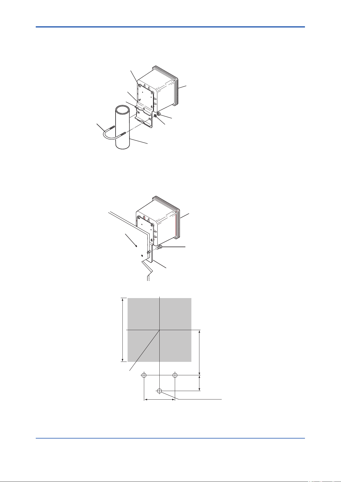
2.2.4 Mounting the Converter
(1) Mounting the GD402G Converter
● Pipe Mounting
Bracket mounting screws
2-8
Bracket
Pipe mounting bracket
U-bolt
Washers (2 pcs)
Stanchion(Ø60.5 mm pipe)
Converter
Nut (2 pcs)
Figure 2.6 Pipe Mounting
● Wall Mounting
Figure 2.3 shows how to mount the converter on a wall.
Converter
Mounting hole (3 places)
Note: The converter for wall
mounting comes with the same
mounting hardware as that of a
pipe-mounting model.
When installing the converter on
a wall, use the bracket only.
Bracket
M8 bolts (not supplied)
Provide bolts of a length suitable
for the mounting holes.
F0206.ai
F0207.ai
144
Center of
the converter
Dimension of cutout for wall mounting
Figure 2.7 Wall Mounting
70
Unit : mm
102
35
3-M8 screw-hole or
3-Ø10 through-holes
F0208.ai
IM 11T3E1-01E
Page 32
<2. Installation, Wiring and Piping>
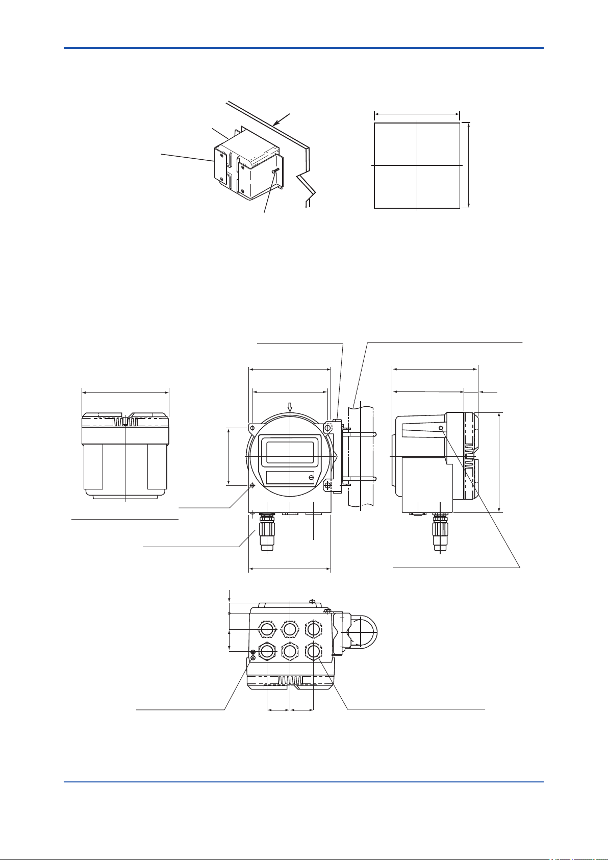
● Panel Mounting
Figure 2.4 shows how to mount the converter on a panel.
2-9
Panel
Converter
Bracket
Insert the converter in
the panel cutout before
attaching the brackets.
Fixing screws (2 pcs)
Figure 2.8 Panel Mounting
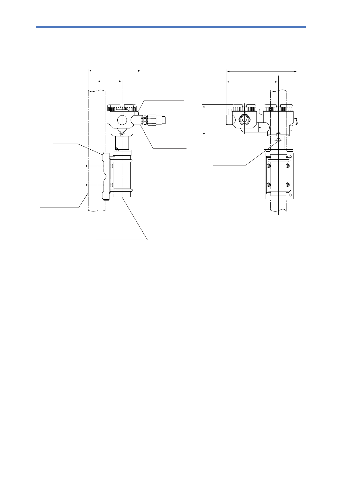
(2) Mounting the GD402T, V, R Converter
Pipe-mounting hardware
200 (7.9)
Φ212 (8.3)
182 (7.2)
A
+2
139
0
Dimensions of cutout for panel mounting
Weight : approx. 15 kg (33.1 pounds)
Mounting pipe of JIS 50 A nominal size (Φ60.5)
209 (8.2)
173 (6.8)
Unit : mm
139
Unit : mm (in.)
+2
0
F0209.ai
36 (1.4)
140 (5.5)
4 - M8 depth 20
Side view from arrow A direction
Cable glands not included
24 (0.9)
39
(1.5)
54
(2.1)
Grounding terminal (M5)
Figure 2.9 Mounting Explosion-proof Converter
200 (7.9)
A B
D ECF
56
56
(2.2)
(2.2)
242 (9.5)
2 - M8 depth 16 (one on each side)
(Used to fix the pipe-mounting hardware)
Six wiring holes, G3/4 threaded (GD402R)
1/2 NPT threaded (GD402V, T)
F0210.ai
IM 11T3E1-01E
Page 33

<2. Installation, Wiring and Piping>
2.3 Piping
CAUTION
In the case of replacement range, H2 in CO2 or Air in CO2, the output happen to be uctuated by
pressure loading to detector. In order to reduce the effect, owmeter is to be set upper side of
detector so that the pressure loading to the detector is going to be about atmospheric pressure.
The piping connected to the analyzer comprises a line that feeds the gas under measurement to
the detector, a line that returns (or releases to the atmosphere) the gas exhausted after measurement, and lines that carry the zero and span calibration gases. The type of piping chosen
depends on the composition of the gas under measurement, its pressure, the amount of dust
mixed, and the response (dead time). It is advisable however to use stainless steel piping of sizes
from 6 mm and 4 mm in outer and inner diameters up to JIS 15 A (21.7mm in outer dia.).
Refer to the following instructions when connecting the analyzer piping.
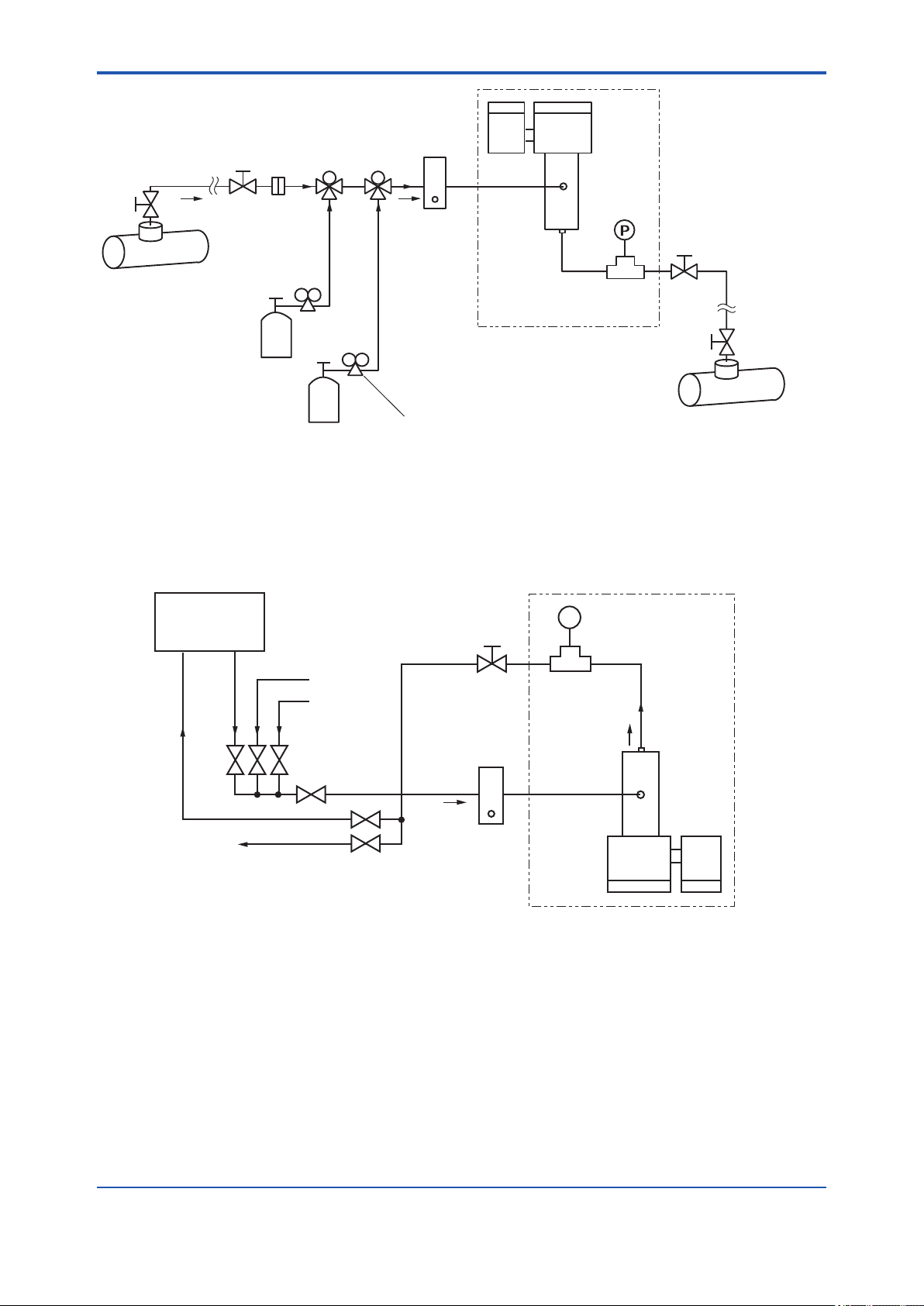
l Figure 2.10, "System Conguration," shows an example of piping. Connect the lines secure-
ly to ensure that there is no gas leakage in the system.
l Make sure the pressure of the sample gas is no greater than 0.5 MPa when measured at
the detector inlet. If the pressure is too high, use a pressure reducing valve to regulate the
pressure to a normal level. If the pressure is too low, it must be raised using a pump.
2-10
l If the gas under measurement contains dust, mist or moisture, such impurities must be
removed. Install a lter, mist separator or dehumidier to remove these impurities from the
gas.
l In order to return the gas exhausted after measurement, the difference in pressure between
the detector inlet and the point of returning the gas must be 0.5 kPa minimum. Choose piping with a large inner diameter to minimize pressure loss in the return gas line.
l ALWAYS install a stop valve at the point where the gas is sampled (or returned).
l The pressure transmitter for compensating pressure is designed to detect the pressure
inside the detector; install a pressure lead pipe as close to the detector as possible (preferably, no more than 0.5 m away).
IM 11T3E1-01E
Page 34
<2. Installation, Wiring and Piping>
2-11
Sample gas line
Note 1: P1 (Inlet pressure)
Note 2: P1 (Inlet pressure) - P2 (Outlet pressure)
Note 3: Flowrate = 0.1 to 1 l/min
Note 4: The cylinder pressure must be reduced to P1 (Inle t pressure).
(1) Example of Gas density and Calorie meters
Gas for zero
calibration
Gas for span
calibration
Switching valve
Filter
Note 4
Note 4
Supplied by customer.
<
Max. 0.5 MPa (71 psi)
=
Note 1
P1
Flowmeter
Note 3
Pressure regulator
for gas cylinder
>
0.5 kPa (0.071 psi) (depending on the size and length of the pipe)
=
Note 2
P2
EJA (Explosion-proof
pressure transmitter)
Detector unit (EJA and GD40 detector
mounted on plate)
(Supplied by Yokogawa)
F0211.ai
Generator
Calibration gas
CO
2
Note 4
AIR
Vent
Note 1 : P1 (Inlet pressure )
<
Max 0.5884 MPa (abs.)
=
Flowmeter
Note 2
Note 2 : Flowrate = 0.1 to 1 l/min
Note 3 : P1 (Input pressure ) - P2 (Output pressure )
>
0.5 kPa
=
Note 4 : The cylinder pressure must be reduced to P1(Inlet pressure).
(2) Example of Hydrogen purity meter
Figure 2.10 System Conguration
Explosion-proof
P
pressure transmitter
Note 1
P1
Detector unit
Note 3
P2
F0212.ai
IM 11T3E1-01E
Page 35
<2. Installation, Wiring and Piping>
2.4 Wiring
WARNING
Danger High Voltage !
Some parts of the meter’s internal assembly have high voltages. Inadvertent contact with those
parts may result in electrical shock or injury. ALWAYS turn off the power to the meter before
removing the rear or front cover by using external circuit breaker.
This section explains how to wire the GD402 Analyzers. Note that this document is limited to the
basic system conguration only (detector, converter and pressure transmitter).
For details on the wiring of instruments used to receive analog output signals or contact output
signals, see their respective instruction manuals.
CAUTION
The GD402 gas density meter is shipped after adjusting the both of detector and converter in
pairs. When installation, conrm whether the serial number on both of converter and detector are
in pairs or not. If mismatched in pairs, converter is to be out of order. When converter or detector
supplied individually, enter the detector constants, described on inside the lid of the GD40, into
converter so that the GD402 is going to be well.
In detail, please refer to Figure 5.30, Figure 6.31 or Figure 7.28.
2-12
2.4.1 Wiring Procedure
(1) The types of cables wired to the GD402 Analyzers are:
• Cable wired to power supply
• Cable wired to detector input
• Cables wired to output signals (two) -- or one signal if BRAIN communication is used
• Cables wired to contact outputs (ve) -- provided as necessary
• Cable wired to contact input -- provided as necessary
• Cables wired to pressure transmitter
• Cables wired to the ground
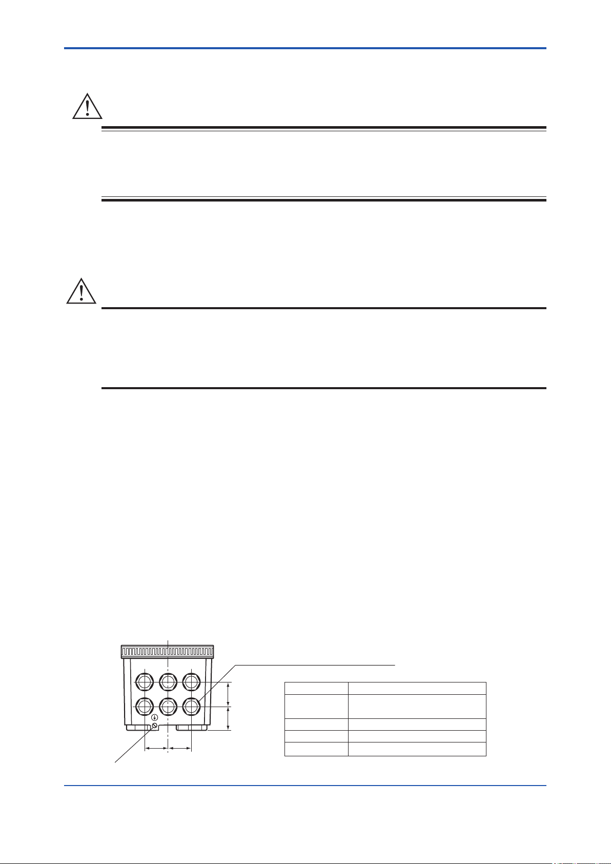
(2) The GD402 converter has six cable inlets for external wiring. Wire the converter through
cable glands. As a rule, choose cable glands as shown in Figure 2.11.
<GD402G>
Cable inlet (21 mm in dia.)
Compatible with a PG 13.5 cable gland
A B
D F
36 36
Grounding terminal (4 mm screws)
C
36
(1.4)
E
(1.4)(1.4)
38
(1.5)
Cable gland Connection
A, B
D, E
F
Weight : Approx. 3 kg (6.6 pounds)
(including mounting hardware)
• Pressure transmitter
• Analog Output • Contact Input
• DetectorC
• Contact Output
• Power Supply
Unit : mm (in.)
F0213.ai
IM 11T3E1-01E
Page 36

<2. Installation, Wiring and Piping>
<GD402T, V, R>
24 (0.9)
39
(1.5)
54
(2.1)
A B
D E
C
F
Cable gland
A
B, C
D
E, F
• Power Supply
• Contact Output
• Detector
• Pressure Transmitter
• Analog Output • Contact Input
2-13
Unit : mm (in.)
Connection
Grounding terminal (M5)
56
(2.2)
56
(2.2)
Six wiring holes, G3/4 threaded (GD402R)
1/2 NPT threaded (GD402V, T)
F0214.ai
(3) The following explains the general wiring procedure for each type of converter.
<Wiring the GD402T, V, R converter>
CAUTION
The rear cover and the metal plugs at the external-wiring connections are xed onto the converter case with hex setscrews. Before removing the cover, be SURE to loosen the setscrews. If you
rotate the cover or a plug without loosening the setscrews, their threads may be severed, making
the cover unremovable.
When the rear cover or any of the cable glands or plugs are removed, handle them with utmost
care so that the threads are not damaged. When re-attaching it on to the converter, clean the
threads so they will not be damaged due to such foreign matters as dust.
• Loosen the setscrews and remove the rear cover by rotating it counterclockwise.
• Guide the required external-wiring cables through the cable glands to the converter.
Exercise care so as to avoid connecting them with the wrong polarities.
• After wiring, securely fasten the rear cover and cable glands.
<Wiring the GD402G converter>
• Loosen the setscrews in the four corners and remove the front cover.
• Remove the terminal cover. Guide the required external-wiring cables through the cable
glands to the converter. Beware of the correct polarities.
• After wiring, reinstall the terminal cover and front cover in place.
IM 11T3E1-01E
Page 37
<2. Installation, Wiring and Piping>
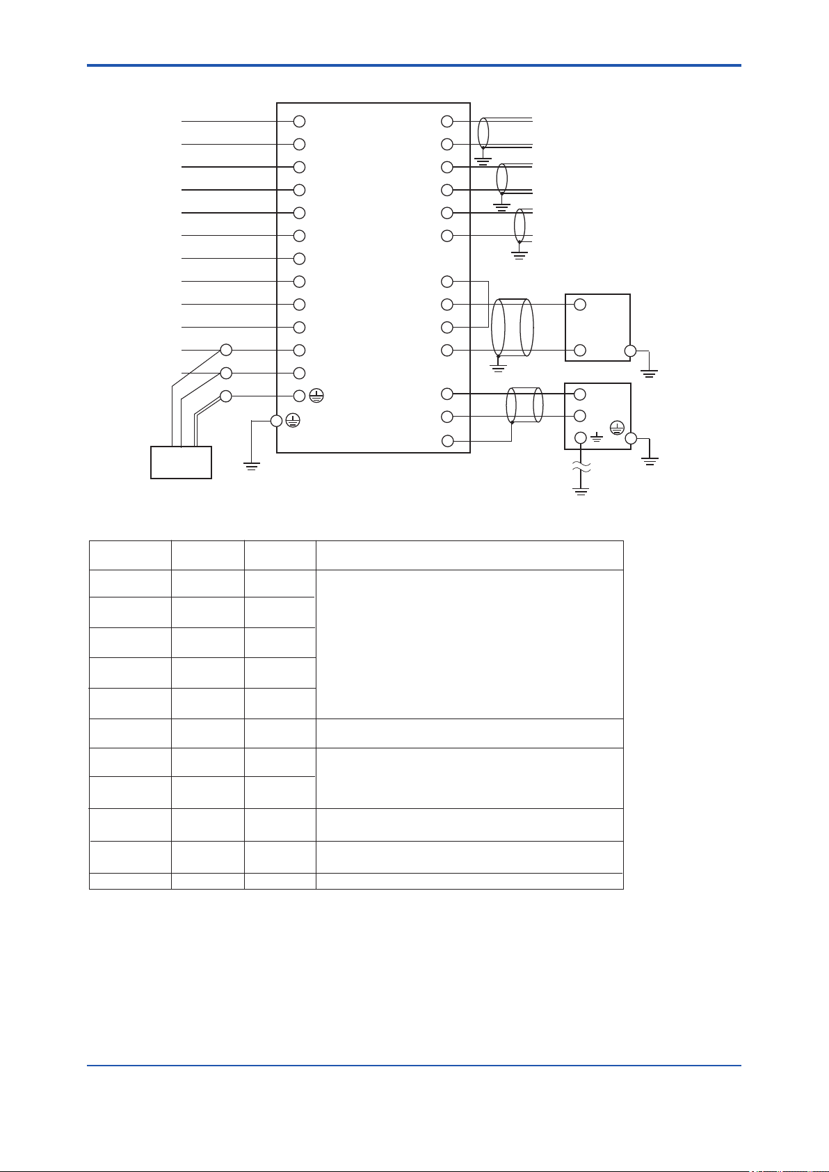
GD402 Converter
2-14
MAINTENANCE
Contact output
ALARM
Contact output
FAIL
Contact output
FUNCTION
Contact output
SELECT GAS
Contact output
Power supply
100 to 240 V AC
or 24 V DC
Surge protector
*1
14
MAINT
15
16
ALM
17
18
FAIL
19
20
SPAN/FUNC
21
22
ZERO/SEL GAS
23
24
L or + -
25
N or -
26
Case grounding
terminal
1
+
CONT
INP
ANLG
OUT1
ANLG
OUT2
SNSR
PWR
SNSR
INP
DET
INP
SHIELD
2
-
3
+
4
-
5
+
6
-
7
+
8
- -
9
+
10
11
+
12
-
13
Intrinsic safety
Grounding
Class A grounding
(grounding resistance
10 Ω or less)
Contact input
Isolated 4-20 mA Output
with BRAIN Communication
Isolated 4-20 mA Output
Pressure Transmitter
Case grounding
+
GD40 Detector
+
-
Case grounding
2
*
*4
terminal
terminal
Cable List
Terminal Indication
MAINTENANCE
Contact output
ALARM
Contact output
FAIL
Contact output
FUNCTION
Contact output
SELECT GAS
Contact output
Contact input CONT IN
Analog output1
Analog output2 ANLG OUT2
Pressure
transmitter input
Detector input
Supply
*1 Surge protector is not provided with GD402T/V/R type converter.
*2 Intrinsic safety grounding
GD402V, GD40V; All wiring should comply with Canadian Electrical Code and Local Electrical Codes.
GD402T, GD40T; All wiring should comply with National Electrical Code and ANSI/NFPA 70 and
Local Electrical Codes.
*3 Restriction on cable length does not apply to GD402T/V/R type converter.
*4 When select GD402T/V/R.
MAINT
ALM
FAIL
SPAN
ZERO
ANLG OUT1
SNSR PWR
SNSR INP
DET INP
SHIELD
L, N, G
Shield
Requirement
Unshielded
Unshielded
Unshielded
Unshielded
Unshielded
Shielded
Shielded
Shielded
Shielded
Shielded
Unshielded
Requirement
For outdoor wiring, cable length should be less than 30 m .
Shield should be grounded at one end only.
Total resistance should not exceed 50 Ω.
For outdoor wiring, cable length should be less than 30 m .
Shield should be grounded at one end only.
Maximum load resistance including wire resistance is 600Ω . When
BRAIN communication is used, it is 250 to 550 Ω.
Total resistance should not exceed 50 Ω.
For outdoor wiring, cable length should be less than 30 m
Shield should be grounded at one end only.
Total resistance should not exceed 50 Ω.
For outdoor wiring, cable length should be less than 30 m
Connect shield to SHIELD terminal on converter.
*
3
*
3
3
*
.
*
3
.
F0215.ai
Figure 2.11 Terminals on the Converter
IM 11T3E1-01E
Page 38

<2. Installation, Wiring and Piping>
CAUTION
The following instructions should be observed for the GD402G converter to meet the CE marking
requirements.
1. Connect the supplied surge protector to the power supply.
2. The length of the following cables should be less than 30 m. However, this restriction does
not apply when both detector and converter stay indoors and their cables do not run outdoors. For details, read Subsection 2.4.1, “Wiring Procedure.”
1) Detector input
2) Pressure transmitter input
3) Analog output1, 2
4) Contact input
Electrical Noise Protection
If a malfunction due to noise occurs, strengthen measures against noise.
For example, ground the detector body or use a double-shielded cable. If a double-shielded cable is used, ground shields of each conductor at one end. Ground one end of the outer shield on
the detector side to the detector case and connect the other end on the converter side to terminal
13. See the User’s Manual for more instructions on cable installation.
2-15
Contact Input Function of the Hydrogen Purity Meter
For hydrogen purity meter, the contact input is used for range selection.
Open: Concentration measurement for Air in CO2
Close: Concentration measurement for H2 in CO2.
Contact Output Specications
Indication Specication
MAINT Contact Type: Voltage free, dry contact (mechanical relay contact output)
ALM
FAIL Contact Type: Voltage free, dry contact (mechanical relay contact output)
SPAN/FUNC Function contact: Use distinguish between the Hydrogen purity meter and
ZERO/SEL GAS
Contact rating: 250 V AC 3 A or 30 V DC 3 A
Contact arrangement: NO/NC, selectable
Contact rating: 250 V AC 3 A or 30 V DC 3 A
Contact arrangement: NC, xed
the Replacement meter.
Select gas contact: Use distinguish measuring ranges in the Replacement meter.
Contact Type: Voltage free, dry contact (mechanical relay contact output)
Contact rating: 250 V AC 3 A or 30 V DC 3 A
Contact arrangement: NO/NC, selectable
IM 11T3E1-01E
Page 39

<2. Installation, Wiring and Piping>
2.4.2 Cables Wired to Power Supply
The GD402G bears the CE marking. When using the meter in a place where the CE marking is
obligatory, or when performance meeting the CE marking requirements is needed, the following
wiring is required. (Note that the following wiring is not required when the power supply is 24 V
DC.)
● Install an external switch or circuit breaker to the power supply of the converter.
● Use an external switch or circuit breaker that is rated at 5 A and conforms to IEC 947-1 or
IEC 947-3.
● Install the external switch or circuit breaker in the same room as the converter is installed.
● The external switch or circuit breaker should be installed in a location that allows operator
access and should be marked a power supply switch to the converter.
● Connect the supplied surge protector to the power supply. This protects the power supply
circuit of the converter from surge.
CAUTION
The GD402R, T, V converter contains a power switch and a fuse. The switch cannot be operated
however, if the converter is installed in an explosion-hazardous area; it must be left placed in the
ON position. When Power ON/OFF, use external circuit breaker
2-16
Wiring is for supplying power supply that meets specications to the GD402 converter.
Use a 3-conductor cable with a size of 1.25 to 2.5 mm2 and an outside diameter of 8 to 16 mm
for 100-240 V AC type and a 2-conductor cable for 24 V DC type. A surge protector is not provided with the GD402T, V, R type converter.
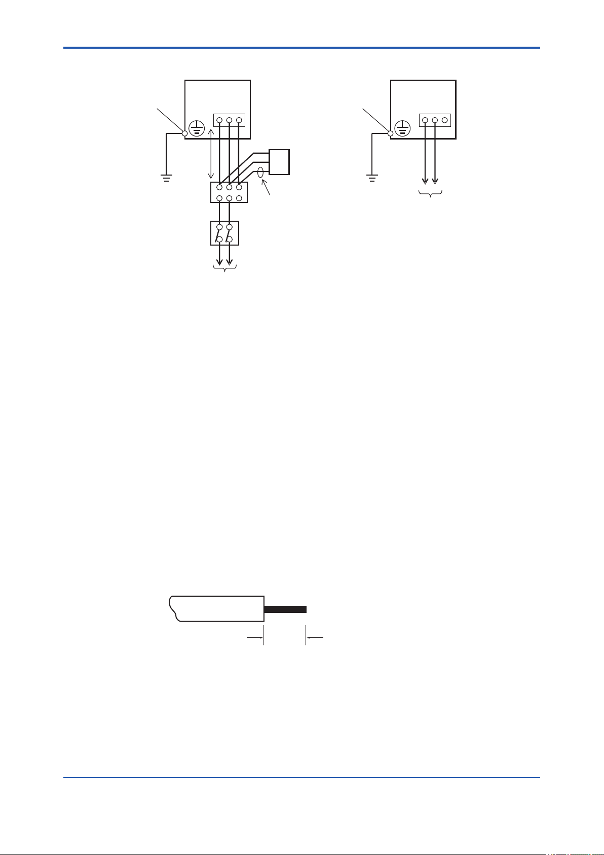
Wire the cable as instructed below:
(1) Strip the sheath 7 mm at the cable end to be connected to the converter.
(2) Connect the cable to terminals L, N, and G or terminals + and - on the converter.
Loosen the terminal screw, insert the stripped part of the wire into the terminal hole,and x
the cable by tightening the screw. (adequate tightening torque: 0.4 N·m)
(3) The length of wire between the converter and a connecting device for the surge protector
should not exceed 1 m.
(4) To connect the surge protector, use a terminal box or relevant device. Wires of the surge
protector have a M4 ring terminal crimped.
(5) Connect black cables of the surge protector to terminals L and N, and the green cable to
terminal G. (Terminal G is internally connected to the case-grounding terminal.)
IM 11T3E1-01E
Page 40
<2. Installation, Wiring and Piping>
2-17
Case-grounding
terminal
GD402 Converter
100-240 V AC type
SUPPLY
L N G
1m
max
100 to 240 V AC
50/60Hz
1 Surge protector and terminal box should be installed in order to meet
*
the requirements of CE marking.
Surge Protector
Green cable
Terminal box
External circuit breaker
Rating: 5 A
Use IEC947-1 or IEC947-3 compliant product.
Figure 2.12 Cables Wired to Power Supply
1
*
Case-grounding
terminal
1
*
GD402 Converter
24 V DC type
SUPPLY
+ - G
24 V DC
F0216.ai
2.4.3 Cables Wired to Outputs
These cables are used to transmit 4-20 mA DC signals and carry out BRAIN communication.
Use shielded cables of 8 to 16 mm in nished outer diameter and 0.75 mm2 minimum in thickness (or a two-core shielded cable for single output).
Wire the cables as instructed below:
(1) Use cables that are 0.75 to 2.5 mm2 thick. Treat the cable ends by stripping the core wires
back 7 mm (see Figure 2.14).
(2) Wire the cable for output 1 to terminals 3 and 4 on the block and the cable for output 2 to
terminals 5 and 6 on the block. Beware of the correct polarities. Note that only terminals 3 and
4 (output 1) are effective for BRAIN communication.
Loosen the terminal screws, insert the stripped ends of the core wires into the terminals, and
fasten the screws to x the cables.
(3) Ground the shielding wire at a given terminal on the converter; do not ground the other end of
the cable. (The appropriate tightening torque for the internal wiring terminals is 0.4 N·m.)
7mm
Figure 2.13 Examples of Treatment on Cable End Wired to the Converter
F0217.ai
IM 11T3E1-01E
Page 41
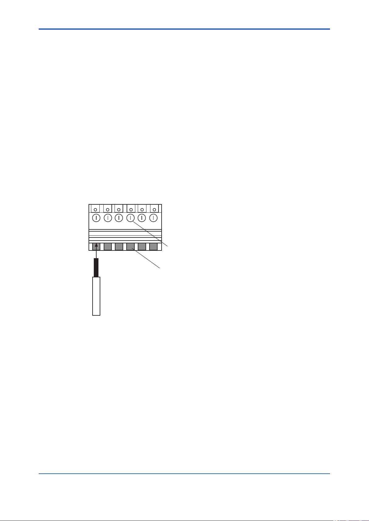
<2. Installation, Wiring and Piping>
2.4.4 Cables Wired to Contact I/Os
The contact I/Os of the GD402 converter comprise the start-of-calibration contact (input), the
FAIL, ALARM and MAINTENANCE contacts, and the contacts for operating the solenoid valves
for span and zero calibrations. Choose the type of cables for a group of calibration-purpose contacts and for a group of other contacts separately.
For wiring to the calibration contact output, use a cable of 8 to 16 mm in nished outer diameter
and 1.25 mm2 minimum in thickness. For wiring to other contacts, use a cable of 8 to 16 mm in
nished outer diameter and 0.13 to 1.25 mm2 in thickness, while choosing the number of core
wires depending on the number of contacts used.
Since the contact outputs are voltage-free, driving such devices as alarm lamps requires a separate power supply. For the contact input (start of calibration), provide a voltage-free signal.
Wire the cables as instructed below:
(1) Use cables 0.13 to 1.25 mm2 thick. Treat the cable ends by stripping back the core wires to 7
mm from the end (see Figure 2.14).
(2) Wire the cables to their respective given terminals on the block, being careful not to mistake
one terminal for another. For terminal numbers assigned to the respective contacts I/Os, see
Figure 2.12.
Loosen the terminal screws, insert the stripped ends of the core wires into the terminals, and
fasten the screws to x the cables. (The appropriate tightening torque is 0.4 N·m)
Terminal
2-18
Tightening screw
Cable inlet
Cable
Figure 2.14 Connection between terminal and cable
F0218.ai
IM 11T3E1-01E
Page 42

<2. Installation, Wiring and Piping>
2.4.5 Cable Wired to GD40 Detector
The cable wired to the GD40 detector comes from the GD402 converter. Use a shielded cable
of 10 to 13.5 mm in nished outer diameter that suits the dedicated cable gland. Wire the cable
through the cable gland, being careful not to connect the cable with the wrong polarities. Attach
M4 crimp terminals to the ends of the core wires (see Figure 2.14). Connect the shielding wire to
terminal 13 on the converter (see Figure 2.12). When crimping the terminals, use tools that t the
terminals.
If a malfunction occurs and it is assumed to be due to noise, use a double-shielded cable (for example, the cable with Yokogawa’s Model GDW-L ). Connect the outer shielding wire to ter-
minal 13 on the converter and the other end of the wire to the grounding terminal on the detector.
Connect the inner shielding wires to the grounding terminal on the converter (see Figure 2.17).
Class A
grounding terminal
2-19
Terminals for
wiring to converter
Figure 2.15 Conguration of Detector Terminals
GD40T, V, R
Detector
Class A
grounding
terminal
Class A
grounding
Outer shielding wire
Do not connect the inner
shielding wires here.
F0219.ai
GD402G, T, V, R
Converter
Inner shielding
wires
11 12 13
Outer shielding
wire
F0220.ai
Figure 2.16 Connection Between Detector and Converter When Using a Double-Shielded Cable
IM 11T3E1-01E
Page 43
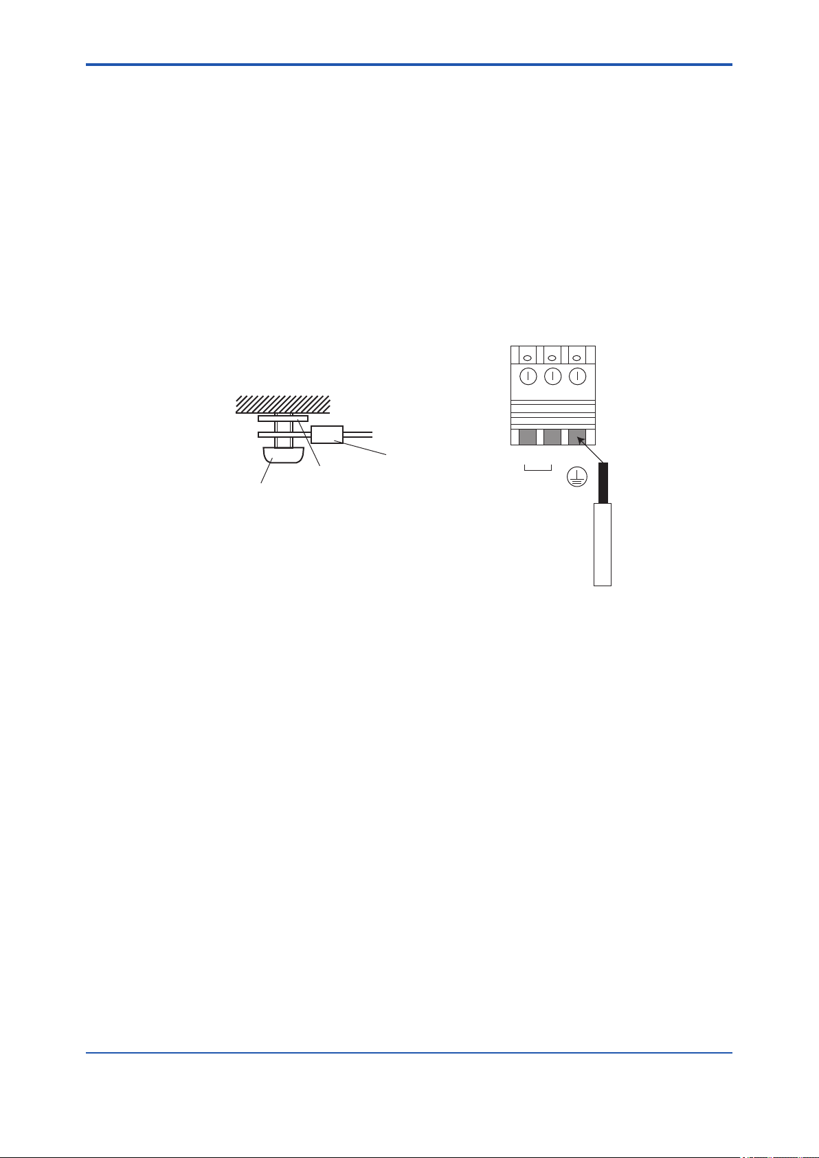
<2. Installation, Wiring and Piping>
2.4.6 Cables Wired to the Ground
When using the GD40R detector in an area requiring explosion protection, BE SURE to ground it
as per the Class A Grounding Standard using a conductor of at least 2 mm2 in nominal thickness.
Also BE SURE to ground the GD402 converter as per the Class D Grounding Standard.
In the case of using GD40T detector, Intrinsically Safe Grounding shall comply with National
Electrical Code ANSI / NFPA 70 and Local Electrical Codes.
In the case of using GD40V detector, Intrinsically Safe Grounding shall comply with Canadian
Electrical Code and Local Electrical Codes.
Use No. 26 internal wiring terminals or the grounding terminals of the converter. (The appropriate
tightening torque for the internal wiring terminals is 0.4 N·m). When using the detector’s grounding terminals, attach M4 crimp terminals to the ends of the grounding cables. When crimping the
terminals, use tools that t the terminals.
TerminalJoining advice of Converter
case ground terminal
Converter case
2-20
Lock washer
Ground terminal
Earthing of enclosure wiring terminal
Figure 2.17 Power and Ground Wiring
Ground wiring
crimp terminal
24 2625
L N
Earth cable
Earthing of internal wiring terminal
F0221.ai
IM 11T3E1-01E
Page 44

<3. Operation>
3. OPERATION
This chapter explains how to operate the GD402 Analyzers.
3.1 Preparation for Operation
CAUTION
(1) DO NOT supply power to the analyzer when inspecting it.
(2) Leave the power switch which is built in the converter, in the ON position.
(3) DO NOT open the terminal box cover with the power turned on, if the analyzer is installed in
an explosion-hazardous area.
(4) When using the converter under high ambient temperatures, be careful as the metal parts of
the converter will also be hot.
3.1.1 Inspecting Installation, Piping and Wiring
3-1
Workmanship
Before turning the power on, inspect workmanship with regards to installation, piping and wiring
as instructed below:
l Examine how the GD402 analyzer and its peripheral equipment are installed.
l Check the sample-gas line, which feeds the GD40 detector, for any gas leakage.
l Inspect the system to ensure that the GD402 analyzer and its peripheral equipment are
wired correctly. After inspection, shut the terminal box cover securely.
l Place the power switch built in the GD402T, GD402V, GD402R converter (explosion-
protected) in the ON position.
IM 11T3E1-01E
Page 45

<3. Operation>
3.1.2 Supplying Power
First make sure that when the GD402 analyzer is turned on, no control instruments connected to
the analyzer will come into operation by the signals transmitted from the analyzer. Next, turn on
the external power switch to start the analyzer. At that point, make sure the internal power switch
is in the ON position if the converter is an explosion-protected model.
After power-on, the analyzer will begin to operate in the measurement mode.
[Major Items Shown in Measurement Mode]
l Measured Values
In the Message selection under the DISP mode, choose the item you want to show.
3-2
Item
Physical density XX.XXXX KG/M3
Physical density X.XXXXX LB/FT3
Compensated density X.XXXX KG/M3
Compensated density X.XXXXX LB/FT3
Caloric value XXX.XXX MJ/M3
Caloric value X.XXXX KBTU
Specic gravity X.XXXX SP GR
Molecular weight XXX.XX MOL
Concentration XXX.X VOL%
No. of Digits and Position
of Decimal Point
Message
l Types of Messages
• Measurement units
• Error number (shown if an error occurs)
• Alarm number (shown if an alarm occurs)
l HOLD and FAIL Indications (shown regardless of whether the analyzer is in the
measurement mode or not)
• HOLD appears when the analyzer is in a hold state.
• FAIL appears if an error occurs.
IM 11T3E1-01E
Page 46

<3. Operation>
3.1.3 Display on Operation Panel and Operation Keys
Figures 3.1 and 3.2 illustrate the operation panels of the Model GD402G and GD402T, GD402V,
GD402R converters, respectively.
The operation panel has a display and operation keys. Use the seven operation keys on the
panel to set operation parameters, and so on.
3-3
State Display
Data Display
Message Display
E X A
GD402
Key operation Display
Operation Key
【YES】: When the blinking "Key Operation
Display" is YES, the YES key is pushed.
【NO】: When the blinking “Key operation
Display" is NO, the NO key is pushed.
【MODE】: When switching from the measure ment mode to the operation mode,
the mode key is pushed. When
switching from modes other than
the measurement to the measurement
mode, the mode key is pushed.
【 】: This switch is used to select the input
data the digit.
【 】: This switch selects the input data value.
【ENT】: When the input data is entered,
this switch is pushed
YES
NO
Figure 3.1 Functional Description of GD402G Converter (Cover Open)
State Display
Data Display
MODE
ENT
MODE
DENSITY
DENSITY (COMP.)
SPEC GRAVITY
CALORIC VALU E
MOL.WEIGH T
VOL.% CON C.
MEASURE
SEL GAS RAN GE
DISPLAY
SEMI CAL.
MANUAL CAL.
VALVE
conta cts
MAINT
ALARM
CAL/SEL
FAIL
MARKINGS
WITHIN
ENCLOSURE
RANGE
CAL DATA
ALARM
SERVICE
Operation level
display panel
Setting level / Service
level display panel
*
Setting level / Service
level selection switch
F0301.ai
Message Display
Key operation Display
Operation Key
MAINT ALARM CAL/SEL EXA GD402FAIL
【YES】: When the blinking
CONTACTS
"Key Operation Display" is YES,
the YES key is pushed.
【NO】: When the blinking “Key operation
Display" is NO, the NO key is pushed.
YES NO MODE
【MODE】: When switching from the measure ment mode to the operation mode,
the mode key is pushed. When
switching from modes other than
the measurement to the measurement
mode, the mode key is pushed.
【 】: This switch is used to select the input
data the digit.
【 】: This switch selects the input data value.
【ENT】: When the input data is entered,
this switch is pushed
Figure 3.2 Functional Description of GD402T, GD402V, GD402R Converter
(Cover Open)
Operation level
display panel
UNIT /MODE
SUB MENU
kg/m3 DENS
kg/m3 DENS COMP
SP 3R
3
MJ/m
MOL WT
vol% conc
MEASURE
RANGE
DISPLAY
SEMI CAL
CAL DATA
ALARM
MANUAL CAL
VALVE
SERVICE
*
ENT
Setting level / Service
level display panel
Setting level / Service
level selection switch
F0302.ai
IM 11T3E1-01E
Page 47

<3. Operation>
F0304.ai
3.1.4 Basic Key Operation
The basics of key operation are the selection between modes/levels, the selection and execution
of the function/action, and entry of data values.
1. Selecting Between Modes at the Operation Level (See Chapter 5, 6 or 7 for details.)
l You can enter the measurement mode by pressing the [MODE] key while the analyzer is in
a mode other than the measurement mode.
When switching between modes, note the following two points:
(1) Press the [MODE] key once. The message eld rst shows ”DISP” in Figure 3.3-(1)
(then password is not selected in rst condition). And then changes to look like one shown
in Figure 3.3-(2).
(1) (2)
3-4
When password is selected, the message field
<*PASSW>, prompting you to enter a passwords.
Type [XXX] and press the [ENT] key. The
message field changes to look like one shown left.
Figure 3.3 Examples of Display at Operation Level (In case of the Density Meter)
In the display shown left, the [YES] and [NO]
fields blink. Pressing the [YES] key will change
the message to [KG/M3], indicating the analyzer
is now in the density mode.
F0303.ai
(2) In the display shown in Figure 3.3-(1), each press of the [NO] key changes the message
eld, enabling you to choose a different mode by its indication.
2. Selecting Between Modes at the Setting Level (See Chapter 5, 6 or 7 for details.)
(1) In the measurement mode, press the [*] key (to select between settings).
(1) (2)
When password is selected, the message field shows
<*PASSW>, prompting you to enter a passwords.
Type [XXX] and press the [ENT] key. The
message field changes to look like one shown left.
Figure 3.4 Examples of Display at Setting Level
In the display shown left, the [YES] and [NO]
fields blink. Pressing the [YES] key will change
the message to read [OUT1] , indicating the
analyzer is now in the analog output setting mode.
(2) In the display shown in 3.4-(1), each press of the [NO] key changes the message eld, ena-
bling you to choose a different mode by its indication.
IM 11T3E1-01E
Page 48
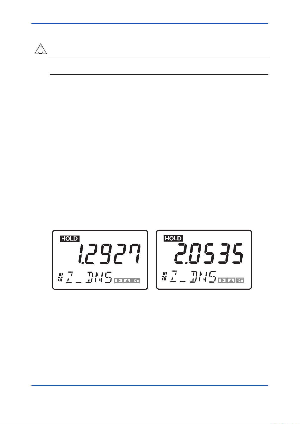
<3. Operation>
3. Entering Data Values
NOTE
The data you have entered keep in memory even if you turn off the power. If the data you have
entered are provisional, reenter the normal data.
The following explains how to make changes to existing data entries.
In the display shown in Figure 3.4-(2), pressing the [YES] key causes the message eld to default
to [*DENS]. Pressing the [YES] key once again changes the message to [*Z_DNS], the range of
lower limit setting, and makes the indication of the lower limit blink.
Assume the existing data entry of the range's lower limit is 1.2927. To change the value to
2.0535, follow the instructions given below:
(1) Press the [>] key so “1“ starts blinking.
3-5
(2) Press the
key until the blinking "1" changes to ''2".
[ ]
>
(3) Press the [>] key until the next digit begins blinking. Then, press the
ing ”2” digit changes to “0".
(4) Press the [>] key until the next digit begins blinking. Then, press the
digit changes to ''5”.
(5) Press the [>] key until the next digit begins blinking. Then, press the
digit changes to ''3”.
(6) Press the [>] key until the next digit begins blinking. Then, press the
ing digit changes to ''5”.
(7) Press the [ENT] key. This conrms the value “2.0535".
(1) (2)
[ ]
>
key until the blink-
key until the blinking
[ ]
>
key until the blinking
[ ]
>
[ ]
>
key until the blink-
In the display shown in Figure 3.4 (2), pressing the
[YES] key will change the display to look like this.
Figure 3.5 Display During Data Setting
Pressing the [ENT] key enters the value shown
in the data field.
F0305.ai
IM 11T3E1-01E
Page 49

<3. Operation>
F0306.ai
4. Entering a Password
If you need, a password can be entered to proceed into the operation, setting or service level.
When you attempt to enter that level, a password-entry message (password prompt) like one
shown in Figure 3.6-(1) appears. The required password is “XXX”. (See section “4.2 Setting
Lists”.)
(1) (2)
3-6
When password is selected, pressing the [MODE]
key, then the [*] key, changes the display to
look like this.
Figure 3.6 Password Prompt and the Reading of a Password Typed
Type the password (XXX) and then press the
[ENT] key. If you type a wrong password,
you cannot enter the level.
3.1.5 Checking the Setting Parameters
Set up the relevant parameters, display unit, analog output and others, to meet individual operating requirements. The GD402 gas density meter is designed to change into density, caloric meter and hydrogen purity meter according to application. (Select “50” in Service code, and change
parameter you need.)
3.1.6 Calibrating the Analyzer for Correct Readings
For details on the calibration of the analyzer for correct readings, see Chapter 8, 9 or 10.
IM 11T3E1-01E
Page 50
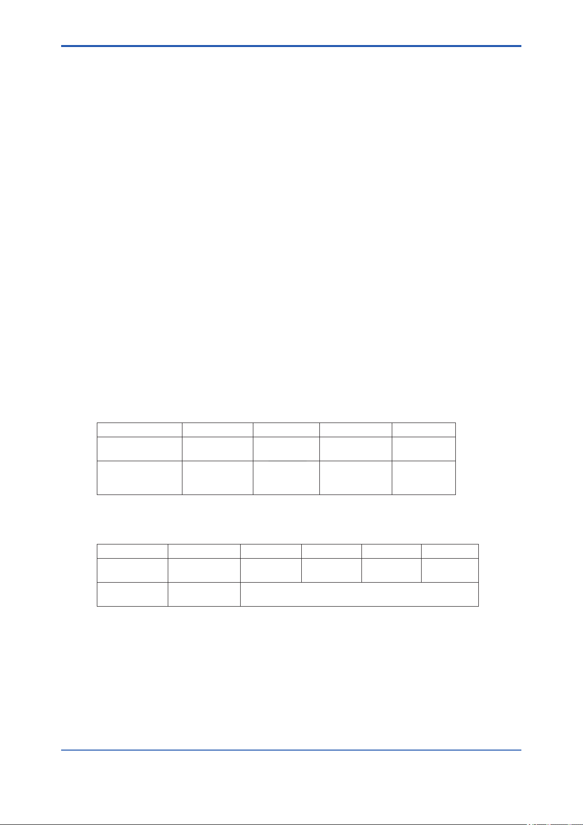
<3. Operation>
3.1.7 Checking the Analyzer for Performance
When the required parameters have been completely set, bring into operation all equipment
composing the measurement loop. Keep this equipment operating for a while. After making sure
there is no problem with the equipment, go into normal operation.
For reference, the following summarizes the setting functions (related to signals) of the GD402
analyzer that are used to obtain the optimum operating conditions.
[Functions Related to the Output Signal]
The output signal can be held at a value immediately before calibration or at a desired value during calibration or at the setting/service level. This is to prevent the output signal from adversely
affecting the operation of the equipment conguring the measurement loop (default setting: the
output signal is held at the value immediately before).
[Functions Related to the High/Low Limit Alarm Contact Output]
Select the parameters for which the alarms are raised, and then set their respective high/low limit
setpoints. The analyzer transmits an alarm contact signal if any of these setpoints is exceeded.
(Dene the voltage-free contacts and the state of contacts at the service level.)
[Functions Related to the FAIL Contact Signal]
If a FAIL state occurs, an appropriate message appears on the LCD display. For details on these
functions, see Chapter 11.
3-7
[Contact output of Hydrogen purity / Replacement meter]
According to switching of Replacement meter, the status of contact and display (LED) is changed
as following. (The status of contact output are to be set in Service level, CODE 05.)
• Hydrogen purity meter
RANGE FUNC SEL GAS LED
Replacement
Meter
Hydrogen Purity/
Replacement Meter
FUNC: Identication signal of Hydrogen purity/Replacement Meter. (contact)
SEL GAS: Range identication signal of Replacement Meter. (contact)
H2 in CO2
AIR in CO2
H2 in AIR
H2 in CO2
AIR in CO2
—
NORMAL
ACTIVE
ACTIVE
ACTIVE
NORMAL
NORMAL
ACTIVE
NORMAL
ON
OFF
OFF
ON
OFF
[The status of contact output]
FAIL SEL FUNC MAINT ALM
Power Supply
OFF
Power SupplyONNORMAL: CLOSE
OPEN CLOSE CLOSE CLOSE CLOSE
FAILURE: OPEN
The status of contact are to be set in Service level, CODE 05.
IM 11T3E1-01E
Page 51

<3. Operation>
3.2 Normal Operation
In normal operation, there is no need for working with the GD402 analyzer except when calibrating it. Unless there is any failure found, carry out maintenance, inspection, and so on at the same
time the analyzer is calibrated. The analyzer is designed to prohibit you from calibrating it or setting each parameter unless you have entered the password (XXX).
(See section “4.2 Setting Lists”.)
3.2.1 Starting Operation
Follow the procedure below to start operation.
Turn on the external power switch.
Set the operating parameters.
Calibrate the analyzer for correct zero and span setpoints.
Completing these steps return to the <MEASURE> mode.
3-8
F0307.ai
The following details the operations required in this procedure.
(1) The analyzer, when turned on, indicates the density value. See Figure 5.2, 6.3 or 7.3 for the
operations used to change to the required unit of density.
(2) Set the relevant operating parameters by checking and modifying their default values in
order to meet individual operating requirements.
(3) Supply the zero and span gases to check readings. If the readings contain errors, the ana-
lyzer must be calibrated. For details on calibration, see Chapter 8, 9 or 10.
(4) When calibration is complete, the analyzer returns to the <MEASURE> mode.
3.2.2 Corrective Actions in Case of Failure
If the GD402 analyzer senses a failure, it sends out a FAIL contact output signal through terminals 18 and 19. In such a case, the output signal is held at either the value held immediately
before or at the preset value for each setting.
The message eld indicates the type of error by the error code. Should a failure occur, check the
nature of the failure and take corrective action without delay. Table 3.1 summarizes the numeric
codes of errors that may occur in the measurement mode. For details on each type of error, see
Table 11.2 on page 11-4.
Table 3.1 Errors that May Occur in the Measurement Mode
Error No. Nature of Failure Corrective Actions
Err. 01 Sensor oscillation shutdown Reset the power and contact service personnel.
Err. 02 Faulty oscillation frequency of sensor Reset the power and contact service personnel.
Err. 03 Sensor’s failure to detect temperature Contact service personnel.
Err. 04 Failure in A/D converter Contact service personnel.
Err. 05 Failure in memory Contact service personnel.
IM 11T3E1-01E
Page 52

<3. Operation>
3.2.3 Inspection and Maintenance
Due to the operating principle (polymodal self-excited oscillation circuitry), the sensor has only
the slightest marginal drift, which is, in fact, generated by the detector itself or a result of contamination from dust, etc. Therefore, the GD402 analyzer basically does not have to undergo any
inspection or maintenance. Periodical inspection and maintenance are recommended however,
to ensure optimum performance. For details on inspection and maintenance, see Chapter 11.
3.3 Shutdown and Restart
3.3.1 Measures for Shutdown
Data set in the converter are retained even when the power is turned off. If the system needs to
be shut down over a prolonged period, turn off the power. Any foreign matter that accumulates
and hardens on the detector or any corrosive substance that condenses on the detector can be
the cause of problems. Fully purge the sensor with fresh air (instrument air). Cleaning of the sensor is also recommended where it is appropriate; consult Yokogawa.
3.3.2 Measures for Restarting
Visually check all component equipment of the analyzer before you resume measurement after a
long-term shutdown of the analyzer. Re-conrm the wiring and piping have tight connections .
3-9
IM 11T3E1-01E
Page 53

Blank Page
Page 54

<4. Functions>
4. FUNCTIONS
When using the GD402 analyzer, set data and select functions according to the measuring
conditions. This chapter describes the structures of function.
4.1 Summary of Setting Operations
4.1.1 Measurement, Operation, Setting and Service
Parameters can be set by selecting the appropriate mode. These modes are classied into four
levels: measurement, operation, setting, and service.
[Measurement Level]
This level is used to view various measured values.
[Operation Level]
This is basically a level used to select between items to be viewed in the measurement mode
and a parameter to be measured, and to perform operations relating to routine inspection and/or
maintenance such as calibration.
[Setting Level]
4-1
At this level, there are modes for setting data related to analog outputs, calibration data and
alarm contact outputs.
[Service Level]
The GD402 analyzer has numerous functions. At this level, there are modes for selecting the
functions necessary for system operation.
4.1.2 Key Operations
Keys can be operated in an "interactive" manner. Operate the keys according to the information
in the data or message eld, information pointed to by the pointer (mode indication), and/or information in the key operation indicators. For basic key operations, see Subsection 3.1.4.
[Interactions]
l Flashing pointer
This inquires whether you want to go to the mode being pointed at or move the pointer to the
next mode. When the system indicates the modes for the setting or service level, the message
is preceded by an asterisk (*). When you enter one of the modes, the pointer stops ashing and
remains continuously lit.
l Flashing key operation indicators
This prompts you to choose an indicator from the indicators ashing on the display and press
the corresponding key.
l Flashing numerals in data eld
This asks whether you want to change the ashing numeral or move to the next digit and have
it ash. Press the appropriate key. If neither of these actions is required, press the [ENT] key.
[Aborting the Setting Operation]
Press the [MODE] key. Normally, the [MODE] key is used to move from the measurement
(<MEASURE>) mode to a mode at the operation level. It is also used to return to the measurement mode from other modes.
IM 11T3E1-01E
Page 55

<4. Functions>
4.1.3 Points to Be Noted When Making Settings
(1) Password
Password is not selected in rst condition. When password is necessary, refer to Section “4.2
Setting Lists” and selected password what you need. If password is selected, you are not allowed
to access any mode unless you enter the given password (XXX).
A password prompt appears when:
l at the operation level, the [MODE] key is pressed during the measurement mode, or
l at the setting level, the [*] key is pressed during the measurement mode.
l at the service level, the [YES] key is pressed with [*SERV] displayed.
(2) Related Parameters
If any change has been made to a particular parameter, check its relationship with parameters
set in other modes so that there will not be any inconsistency.
[Parameters to Check When the Analog Output Settings Are Changed]
a. High/low limit alarm setpoints and contact outputs
b. Fixed value for held output signal
[Parameters to Check When High/Low limit Alarm Setpoints Are Changed]
4-2
a. Alarm actions (low limit alarm or high limit alarm operation)
b. Analog output settings
4.2 Setting Lists
The GD402 Gas Density meter comes in 3 different models (and model codes) to meet several
measurement conditions: (1) Density meter, (2) Calorie meter, and (3) Hydrogen purity meter.
The values measured by the different models are as follows.
(1) Density meter : Density, compensated density, specic gravity, molecular weight,
concentration and calorie.
(2) Calorie meter : Density, compensated density, and calorie
(3) Hydrogen purity meter : Density, compensated density, H2 in Air, Air in CO2, and H2 in
The following describes the conditions required when using the GD402 Gas Density meter.
After following the procedure below, set a model code and select a password.
(1) Select a model code for each service in “Selecting the instruments” function of each service
code. For example, if you select model 1, you can use the analyzer as a calorie meter. (See
Figure 5.29, Figure 6.30 or Figure 7.27.)
CO2.
code 0 : Density meter
1 : Calorie meter
2 : Hydrogen purity meter
(2) Next, set a password, if you need. (See Figure 5.27, Figure 6.28 or Figure 7.25.)
(3) Other parameter settings can now be set.
Set parameters according to the selected model code and password.
(1) Density meter:See Chapter 5. , (2) Calorie meter: See Chapter 6. , (3) Hydrogen pu-
rity meter: See Chapter 7.
IM 11T3E1-01E
Page 56

<5. DENSITY / PARAMETER SETTING>
5. DENSITY / PARAMETER SETTING
CAUTION
Password is not selected in rst condition. When password is necessary, refer to Section “4.2
Setting Lists”.
This chapter describes how to set parameters of Density meter.
If select Calorie meter, see Chapter 6.
If select Hydrogen purity meter, see Chapter 7.
Conversion Table
1 lb/ft3 = 16.01847 kg/m
1 kBTU/ft3 = 37.25901232 MJ/m
X degF = (X-32)/1.8
1 psi = 6.894756794 kPa
Density of Air = 1.2928 kg/m
= 0.08070684 lb/ft
3
3
3
3
5-1
IM 11T3E1-01E
Page 57

<5. DENSITY / PARAMETER SETTING>
5.1 Setting Parameters
Subsections 5.1.1 to 5.1.4 show the setting parameters for each level.
5.1.1 Setting Parameters at Measurement Level
When turned on, the analyzer starts up in the measurement mode (<MEASURE>).
Table 5.1 Setting Parameters at Measurement Level
5-2
Mode/Setting parameter Display
Measurement mode
Indication of measurement value
Physical density
Compensated density
Specic gravity
Caloric value
Molecular weight
Concentration
Indication of message
Unit
Error symbol and number
Alarm mark and number
Indication of HOLD and FAIL
HOLD
FAIL
DISP mode
Physical density
Compensated density
Specic gravity
Caloric value
Molecular weight
Concentration
Sample gas temperature
Sample gas pressure
Analog output 1 (%)
Analog output 2 (%)
KG/M3
LB/FT3
KG/M3
LB/FT3
SP GR
MJ/M3
KBTU
MOL
VOL%
ERR.NO
ALM.NO
HOLD
FAIL
DISP
KG/M3
LB/FT3
KG/M3
LB/FT3
SP GR
MJ/M3
KBTU
MOL
VOL%
ºC
ºF
KPA
MPA
PSI
MA1%
MA2%
Data to be Set
(or Conditions)
Set the unit in CODE 21.
Set the unit in CODE 21.
Set the unit in CODE 22.
Set the unit in CODE 21.
Set the unit in CODE 21.
Set the unit in CODE 22.
Set the unit in CODE 23.
Set the unit in CODE 20.
Remarks
See Figure 5.2 for key operation.
The unit is the one set in the service level.
Appears if an error occurs.
Appears if an alarm occurs.
Appears even during other modes.
Appears during a HOLD state.
Appears if a failure occurs.
See Figure 5.2 for key operation.
Selection of parameters to be measured in
the measurement mode.
Read-only
Read-only
Read-only
Read-only
IM 11T3E1-01E
Page 58
<5. DENSITY / PARAMETER SETTING>
5.1.2 Setting Parameters at Operation Level
Press the [MODE] key and enter the password (XXX) to gain access to this level (see Figure 5.1
for key operation).
Table 5.2 Setting Parameters at Operation Level
5-3
Mode/Setting parameter Display
Calibration mode
Semi-automatic calibration
Manual calibration
Setting of zero-point density
Setting of span-point density
Zero/span-gas valve operation
Zero-gas valve operation
Span-gas valve operation
Sample-gas valve operation
SEM.CAL
MAN.CAL
Z_DNS
S_DNS
VALVE
V_ZERO
V_SPAN
Data to be Set
(or Conditions)
One-touch calibration See Figure 8.3 for key operation.
See Figure 8.4 for key operation.
No setting is required for
manual calibration
Control of zero-gas valve
Control of span-gas valve
Switching between sample and calibration gases
See Figure 8.1 for key operation.
Remarks
IM 11T3E1-01E
Page 59

<5. DENSITY / PARAMETER SETTING>
5.1.3 Setting Parameters at Setting Level
Press the [*] key and enter the password (XXX) to gain access to this level (see Figure 5.4 for key
operation).
Table 5.3 Setting Parameters at Setting Level
5-4
Mode/Setting parameter Display
Analog output setting
Output 1
Set a parameter to be output
Set the zero and span points
Physical density
Compensated density
Specic gravity
Caloric value
Molecular weight
Concentration
*Z_DNS,*S_DNS
*Z_CP.D,*S_CP.D
*Z_SPC,*S_SPC
*Z_CAL,*S_CAL
*Z_MOL,*S_MOL
*Z_CON,*S_CON
Output 2 (same as output 1)
Setting calibration data
Zero-point density
Span-point density
Output hold value during calibration
Setting of preset value
(Only if the preceding parameter is set to 2 (preset value))
Alarm-point setting
Select a parameter for which an
alarm is set
Physical density
Compensated density
Specic gravity
Caloric value
Molecular weight
Concentration
Set the high/low limits
Physical density
Compensated density
Specic gravity
Caloric value
Molecular weight
Concentration
*L_DNS,*H_DNS
*L_CP.D,*H_CP.D
*L_SPC,*H_SPC
*L_CAL,*H_CAL
*L_MOL,*H_MOL
*L_CON,*H_CON
*RANGE
*OUT1
*DENS
*C_DNS
*SP_GR
*CALRY
*MOL
*CONCT
*TEMP
*PRESS
*OUT2
*CAL.DT
*Z_DNS
*S_DNS
*C_HLD
*PR.SET
*ALARM
*DENS
*C_DNS
*SP_GR
*CALRY
*MOL
*CONCT
Data to be Set
(or Conditions)
Physical density
Compensated density
Specic gravity
Caloric value
Molecular weight
Concentration
Gas temperature
Gas pressure
00.0000 to 60.0000 kg/m
0.00000 to 4.00000 lb/ft
0.0000 to 6.0000 kg/m
3
0.00000 to 0.40000 lb/ft
0.0000 to 5.0000
000.000 to 133.000 MJ/m
0.0000 to 3.5000 kBTU/ft
000.00 to 140.00
000.0 to 100.0
0.0000 to 6.0000 kg/m
0.00000 to 0.40000 lb/ft
0.0000 to 6.0000 kg/m
3
3
0.00000 to 0.40000 lb/ft
· Disable: 0
·
Enable (value
immediately before) : 1
·
Enable (preset value) : 2
-10.0 to 110.0
00.0000 to 60.0000 kg/m
0.00000 to 4.00000 lb/ft
0.0000 to 6.0000 kg/m
3
0.00000 to 0.400000 lb/ft
0.0000 to 5.0000
000.000 to 133.000 MJ/m
0.0000 to 3.5000 kBTU/ft
000.00 to 140.00
000.0 to 100.0
Remarks
See Figure 5.4 for key operation.
No setting is required if the parameter
is temperature or pressure.
3
3
3
3
3
See Figure 8.2 for key operation.
3
3
See Figure 5.5 for key operation.
3
3
3
3
3
IM 11T3E1-01E
Page 60

<5. DENSITY / PARAMETER SETTING>
5.1.4 Setting Parameters at Service Level
Press the [*] key and enter the password (XXX) to select the service level. When you select this
level, the analyzer shows a Code No. promptly. Type the appropriate code number and press the
[ENT] key.
Table 5.4 Setting Parameters at Service Level
Code
No.
01 Setting of hold during maintenance
Hold enable/disable
Setting of preset hold value
02 Setting of hold against errors
Hold enable/disable
Setting of preset hold value
04 Setting of output-smoothing constants *SMOTH 00 to 60 See Figure 5.9 for key operation.
05 Setting of contact outputs status *CNTCT 00 to 15 See Figure 5.10 for key operation.
10 Setting of pressure compensation
Enable/disable/xed value
Setting of xed value for pressure
compensation
11 Setting for compensated density
measurement
Setting of reference temperature
Setting of reference pressure
12 Setting of gas pressure
Setting of zero gas pressure
Setting of span gas pressure
13 Selection for automatic calibration *AUTO.C · Disable : 0
14 Setting for remote semi-automatic
calibration
15 Setting of data for automatic/semi-
automatic calibration
Selection of calibration item
Setting of calibration time
Setting of stabilization time
Setting of calibration starting time
Setting of year/month/day
Setting of hour/minute
Selection of unit of calibration
interval
Item Display
*M_HLD
*PR.SET
*E_HLD
*PR.SET
*P.COMP
*P.FIX
*C.D.TMP
*C.D.PRS
*Z_PRS
*S_PRS
*REMOT · Disable : 0
*CAL.P
*CAL.T
*STAB.T
*Y_M_D
*H_M
*CYCL.U
Data to be Set
(or Conditions)
· Disable : 0
· Enable (value immediately
before) : 1
· Enable (preset value) : 2
-10.0 to 110.0
· Disable : 0
· Enable (value immediately
before) : 1
· Enable (preset value) : 2
-10.0 to 110.0
· Disable: 0
· Enable (measured value) : 1
· Enable (xed value) : 2
0.10 to 999.99 kPa, 0.0001 to
9.9999 MPa, 0.015 to 99.999
psi
-20.0 to 80.0 °C, - 4.0 to 176.0 °F
0.10 to 999.99 kPa, 0.0001 to
9.9999 MPa, 0.015 to 99.999
psi
0.01 to 999.99 kPa, 0.0001 to
9.9999 MPa, 0.015 to 99.999 psi
0.10 to 999.99 kPa, 0.0001 to
9.9999 MPa, 0.015 to 99.999 psi
· Enable : 1
· Enable : 1
Zero and span : 0
Zero : 1
Span : 2
00 to 60
00 to 60
00.01.01 to 99.12.31
00.00 to 23.59
Hour : 0
Day : 1
Remarks
See Figure 5.7 for key operation.
If “preset value” is selected in the
preceding parameter.
See Figure 5.8 for key operation.
If “preset value” is selected in the
preceding parameter.
See Figure 5.11 for key operation.
If “xed value” is selected in the
preceding parameter.
See Figure 5.12 for key operation.
See Figure 5.13 for key operation.
See Figure 5.14 for key operation.
See Figure 5.15 for key operation.
See Figure 5.16 for key operation.
5-5
Selection of calibration interval
*CYCL.T
Hour : 00 to 23
Day : 000 to 255
IM 11T3E1-01E
Page 61

<5. DENSITY / PARAMETER SETTING>
Table 5.4 Setting Parameters at Service Level
Code
No.
20 Selection of pressure unit *PRES.U · kPa : 0
21 Selection of density unit *DENS.U · kg/m3 : 0
22 Selection of caloric value unit *CAL.U · MJ/m3 : 0
23 Selection of temperature unit *TEMP.U · °C : 0
30 Setting of calendar
Setting of year/month/day
Setting of hour/minute
31 Showing/hiding of negative measured
values (-)
40 Indication of calibration coefcients
(read-only)
Zero
Span
41 Indication of oscillation frequency
(read-only)
Frequency F2
Frequency F4
Frequency ratio
42 Indication of software version
(read-only)
43 Setting of high-resolution mode *S_CYC · Normal : 0
44 Setting of password *PASS 0.0.0 to 9.9.9 See Figure 5.27 for key operation.
45 Selecting Battery alarm detection *BAT · Non detection : 0
50 Selecting the instruments *MODEL · Density meter : 0
82 Setting Detector Constant See Figure 5.30 for key operation.
Item Display
*Y_M_D
*H_M
*MINUS · Show : 0
*C_K_Z
*C_K_S
*F2.KHZ
*F4.KHZ
*F2/F4
*REV X.XX See Figure 5.25 for key operation.
Data to be Set
(or Conditions)
· MPa : 1
· psi : 2
· lb/ft3 : 1
· kBTU/ft3 : 1
· °F : 1
00.01.01 to 99.12.31
00.00 to 23.59
· Hide : 1
SX.XXXX
X.XXXX
X.XXXXX
X.XXXXX
X.XXXXX
· High-resolution : 1
· Detection : 1
· Calorie meter : 1
·
Hydrogen purity, replacement
meter : 2
Remarks
See Figure 5.17 for key operation.
See Figure 5.18 for key operation.
See Figure 5.19 for key operation.
See Figure 5.20 for key operation.
See Figure 5.21 for key operation.
For leap years, the setting can
cope with ‘February 29’.
See Figure 5.22 for key operation.
See Figure 5.23 for key operation.
S of SX.XXXX means Marks such
as a plus or the minus.
See Figure 5.24 for key operation.
See Figure 5.26 for key operation.
See Figure 5.28 for key operation.
See Figure 5.29 for key operation.
5-6
5.2 Parameter Setting
[Aborting the Setting Operation]
Press the [MODE] key. Normally, the [MODE] key is used to move from the measurement
(<MEASURE>) mode to a mode at the operation level. It is also used to return to the measurement mode from other modes.
5.2.1 Parameter Setting at Operation Level
To move to the operation level, press the [MODE] key and then enter the password (XXX). Password is not selected in rst condition. When password is necessary, refer to Section 4.2 “Setting
Lists” and selected password what you need.
IM 11T3E1-01E
Page 62
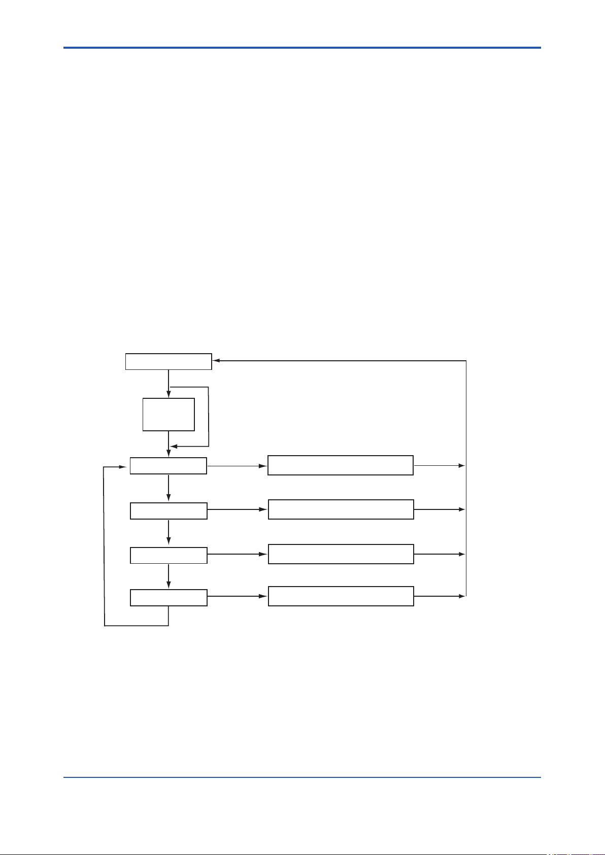
<5. DENSITY / PARAMETER SETTING>
The operation level offers two mode categories: the measurement and calibration operation
modes.
Note that the function for which you have set a data value at the setting level does not work at
all if that function is turned off at another level. For this reason, care must be taken when dealing
with modes that relate to each other.
This subsection explains the operating procedures for the levels/modes noted below.
The calibration operation mode is discussed in Chapter 8.
(1) Operation level
(2) Display mode (DISP mode)
(1) Operation Level
Select a mode from the following four choices of the operation level. Each press of the [NO] key
cycles through the choices in the order shown below:
1. Display mode [DISP]
2. Semi-automatic calibration mode [SEM.CAL]
3. Manual calibration mode [MAN.CAL]
4. Valve operation mode [VALVE]
5-7
Press the [YES] key to enter the desired mode when it is indicated.
Measurement Mode
[MODE]
XXX
*PASSW
[ENT]
DISP
SEM.CAL
MAN.CAL
[NO]
VALVE
[NO]
Password is not selected in first condition
(See "Figure 5.27 Setting of Password" on page 5-31.)
DISP mode
Manual calibration mode
Valve operation mode
[NO]
[NO]
[YES]
[YES]
[YES]
[YES]
See the process in Figure 5.2.
Semi-automatic calibration mode
See the process in Figure 8.3.
See the process in Figure 8.4.
See the process in Figure 8.1.
[YES]
[YES]
[YES]
[YES]
F0501.ai
You can abort the setting operation in any of the modes by pressing [MODE] key.
Doing this will return the analyzer to the measurement mode.
Figure 5.1 Modes of Operation Level
IM 11T3E1-01E
Page 63

<5. DENSITY / PARAMETER SETTING>
(2) Display Mode
Select one of the following ten parameters to be shown in the message eld. Each press of the
[NO] key cycles through the choices in the order shown below:
1. Physical density [XX.XXXX KG/M3] or [X.XXXXX LB/FT3]
(depends on the setting of CODE 21)
2. Compensated density [X.XXXX KG/M3 ]or [X.XXXXX LB/FT3]
(depends on the setting of CODE 21)
3. Specic gravity [X.XXXX SP GR]
4. Caloric value [XXX.XXX MJ/M3] or [X.XXXX KBTU]
(depends on the setting of CODE 22)
5. Molecular weight [XXX.XX MOL]
6. Concentration[XXX.X VOL% ]
7. Temperature [XXX.X °C] or [XXX.X °F]
(depends on the setting of CODE 23)
8. Pressure [XXX.XX KPA] or [X.XXXX MPA] or [XX.XXX PSI]
(depends on the setting of CODE 20)
9. Current for analog output 1 (%) [XXX.X MA1%]
10. Current for analog output 2(%) [XXX.X MA 2%]
5-8
Show the desired choice and press the [YES] key. That choice is set as a parameter to be
measured in the measurement mode (<MEASURE>). Parameters 1 to 6 are congurable, while
parameters 7 to 10 are read-only.
IM 11T3E1-01E
Page 64
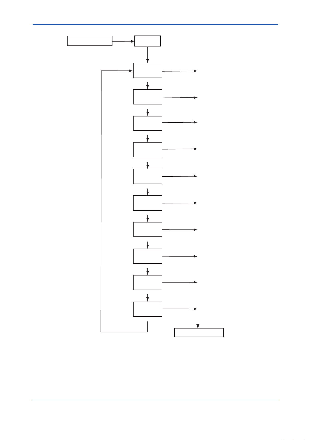
<5. DENSITY / PARAMETER SETTING>
[MODE]
1
Measurement Mode
*
DISP
[YES]
XX.XXXX
[YES]
*
2,* 3
KG/M3
(Physical density)
[NO]
X.XXXX
[YES]
*
2,* 3
KG/M3
(Compensated density)
[NO]
X.XXXX
[YES]
3
*
SP GR
(Specific gravity)
[NO]
XXX.XXX
[YES]
2,* 3
*
MJ/M3
(Calorific value)
[NO]
XXX.XX
[YES]
3
*
MOL
(Molecular weight)
[NO]
XXX.X
[YES]
3
*
VOL%
(Concentration)
[NO]
2
XXX.X
°C
(Sample gas temperature)
[NO]
XXX.XX
KPA
(Sample gas pressure)
*
[YES]
(Read-only)
*
[YES]
(Read-only)
2
[NO]
XXX.X
MA1%
(Current for analog output1(%))
[YES]
(Read-only)
[NO]
XXX.X
MA2%
(Current for analog output 2(%))
[YES]
(Read-only)
[NO]
Measurement Mode
*1: See "Figure 5.1 Modes of Operation Level" on page 5-7.
*2: The unit is the one set in the service level.
*3: Press the [YES] key to show the parameter in the measurement mode.
F0502.ai
5-9
Figure 5.2 Display Mode (DISP Mode)
IM 11T3E1-01E
Page 65

<5. DENSITY / PARAMETER SETTING>
5.2.2 Parameter Setting at Setting Level
To move to the setting level, press the [*] key and then enter the password (XXX). The main task
at the setting level is to set data values such as the measuring range values.
Note that the function for which you have set data values at the setting level, will not work if that
function is turned off at another level. For this reason, care must be taken when dealing with
modes that relate to each other. The setting level has four levels/modes, as shown below, although this subsection explains only the analog output setting and alarm-point setting modes.
The calibration parameter setting mode is discussed in Chapter 8.
1. Analog output setting mode [*RANGE]
2. Calibration parameter setting mode [*CAL.DT]
3. Alarm-point setting mode [*ALARM]
4. Service level [*SERVC]
Select a mode from the above four choices. Each press of the [NO] key cycles through the
choices in sequence. Press the [YES] key to enter the desired mode when it is indicated.
Measurement Mode
[*]
5-10
XXX
*PASSW
[ENT]
*RANGE
[NO]
*CAL.DT
[NO]
*ALARM
[NO]
*SERVC
[NO]
You can abort the setting operation in any of the modes by pressing the [MODE] key.
Doing this will return the analyzer to the measurement mode.
Figure 5.3 Process at the Setting Level
Password is not selected in first condition.
(See "Figure 5.27 Process of Setting Password" on page 5-31.)
[YES]
[YES]
[YES]
[YES]
Analog output setting mode
See the process in Figure 5.4.
Calibration parameter setting mode
See the process in Figure 8.2.
Alarm-point setting mode
See the process in Figure 5.5.
Service level
See the process in Figure 5.7 to 5.30.
[ENT]
[ENT]
[ENT]
[ENT]
F0503.ai
IM 11T3E1-01E
Page 66

<5. DENSITY / PARAMETER SETTING>
1. Analog Output Setting Mode [ *RANGE ]
The analog output has output 1 and output 2. Only output 1 can be used for communication
purposes.
Set a range appropriate for 4-20 mA DC output signals. The range has two setpoints: the lower
limit (zero point) of the range corresponding to the minimum (0%) of a given output signal and the
upper limit (span point) of the range corresponding to the maximum (100%) of the given output
signal.
(1) Output1 [*OUT1]
(a) Select a parameter to be output.
・ Physical density [*DENS]
・ Compensated density [*C_DNS]
・ Specic gravity [*SP_GR]
・ Caloric value [*CALRY]
・ Molecular weight [*MOL]
・ Concentration [*CONCT]
・ Gas temperature [*TEMP]
5-11
・ Gas pressure [*PRESS]
(b) Set the zero and span points. (This item is not applied if temperature or pressure are cho-
sen as the parameter in item (a) above.)
・ Physical density [*Z_DNS], [*S_DNS]
Congure range: 00.0000 to 60.0000 (kg/m3),
0.00000 to 4.00000 (lb/ft3)
・ Compensated density [*Z_CP.D], [*S_CP.D]
Congure range: 0.0000 to 6.0000 (kg/m3),
0.00000 to 0.40000 (lb/ft3)
・ Specic gravity [*Z_SPC], [*S_SPC]
Congure range: 0.0000 to 5.0000
・ Caloric value [*Z_CAL], [*S_CAL]
Congure range: 000.000 to 133.000(MJ/m3),
0.0000 to 3.5000 (kBTU/ft3)
・ Molecular weight [*Z_MOL], [*S_MOL]
Congure range: 000.00 to 140.00
・ Concentration [*Z_CON], [*S_CON]
Congure range: 000.0 to 100.0
(2) Output2 [*OUT2]
The same parameters as those of item (1) apply.
IM 11T3E1-01E
Page 67
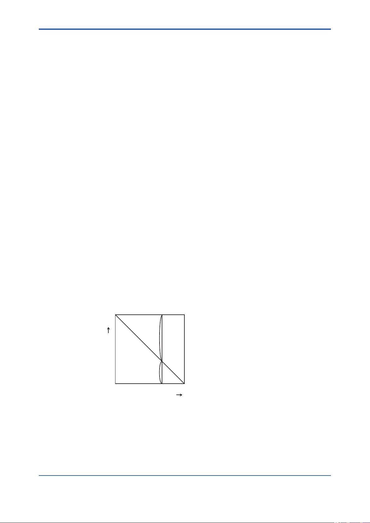
<5. DENSITY / PARAMETER SETTING>
(3) Entries for Calorie and Concentration Measurement
Measuring the caloric value (or concentration) requires the density to be correlated with the
caloric value (or concentration) by a linear equation (linear proportion).
Therefore, use the gas calorie meter in order to measure the caloric value as accurately as possible.
The relationship must be given by Y=aX+b, where Y is the caloric value (MJ/m3) and X is the
density (kg/m3).
l Example of Entries for Calorie Measurement
Assuming the relationship is given by “caloric value = 58 × density + 6 (MJ/m3)”, the density
ranges from 0.5 to 0.7 kg/m3 while the caloric value ranges from 35 to 46.6 MJ/m3.
The entries for the [*CALRY] parameter (see Figure 5.4) therefore are:
*Z_CAL: 35
*S_CAL: 46.6
*Z_CL.D: 0.5
*S_CL.D: 0.7
l Example of Entries for Concentration Measurement
Assume we measure the concentration of hydrogen mixed with nitrogen and the relationship
is given by:
5-12
D = aX +b
where,
D=density of gas being measured (hydrogen: 0.0899 kg/m3; nitrogen: 1.2504 kg/m3),
and
X=volume percent (vol %) of hydrogen gas,
then the equation above is calculated as:
D= (0.0899-1.2504)(X/100) + 1.2504
= -1.1605(X/100) + 1.2504
1.2504
H2
F0504.ai
(D)
Density
0.0899
N2
(1-X)
0 100
Volume percent (VOL%)
X
The entries for the [*CONCT] parameter (see Figure 5.4) therefore are:
*Z_CON: 0
*S_CON: 100
*Z_CN.D: 1.2504
*S_CN.D: 0.0899
IM 11T3E1-01E
Page 68
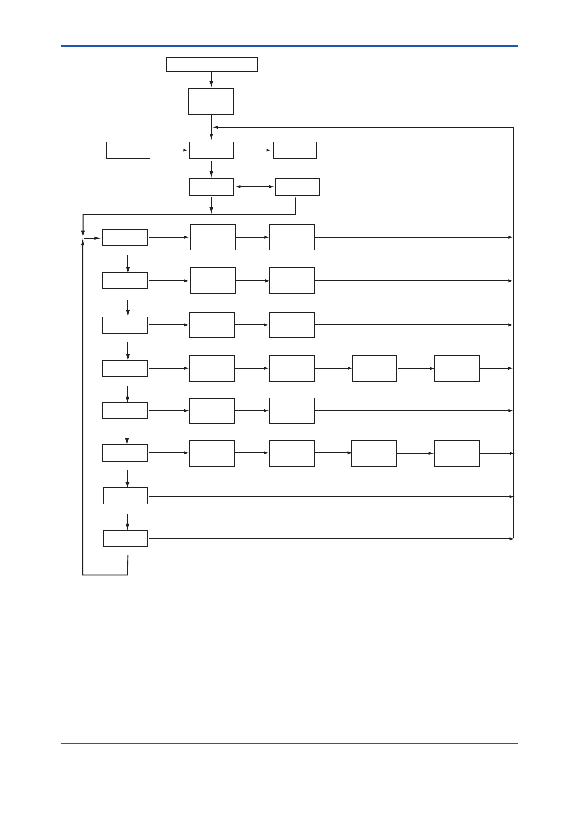
<5. DENSITY / PARAMETER SETTING>
1
Measurement mode
*
[
]
*
XXX
*PASSW
[ENT]
Password is not selected in first condition.
5-13
*SERVC
2
*
*DENS
(Physical density Range)
[NO]
*C_DNS
(Compensated density Range)
[NO]
*SP_GR
(Specific gravity Range)
[NO]
*CALRY
(Calorific value Range)
[NO]
*MOL
(Molecular weight Range)
[NO]
*CONCT
(Concentration Range)
[NO]
[NO]
[YES]
[YES]
[YES]
[YES]
[YES]
[YES]
*RANGE
[YES]
*OUT1
XX.XXXX
*Z_DNS
X.XXXX
*Z_CP.D
X.XXXX
*Z_SPC
XXX.XXX
*Z_CAL
XXX.XX
*Z_MOL
XXX.X
*Z_CON
[NO]
3
*
[NO]
[ENT]
[ENT]
[ENT]
[ENT]
[ENT]
[ENT]
*CAL.DT
*OUT2
XX.XXXX
*S_DNS
X.XXXX
*S_CP.D
X.XXXX
*S_SPC
XXX.XXX
*S_CAL
XXX.XX
*S_MOL
XXX.X
*S_CON
[YES][YES]
[ENT]
[ENT]
[ENT]
[ENT]
[ENT]
[ENT]
X.XXXX
*Z_CL.D
X.XXXX
*Z_CN.D
[ENT]
[ENT] [ENT]
X.XXXX
*S_CL.D
X.XXXX
*S_CN.D
[ENT]
*TEMP
(Gas temperature)
[NO]
*PRESS
(Gas pressure)
[NO]
*1: You can abort the setting operation in any of the modes by pressing [MODE] key.
Doing this will return the analyzer to the measurement mode.
*2: The display shows the previous parameter first.
*3: Each press of the [NO] key toggles between the parameters [*OUT1] and [*OUT2].
[YES]
[YES]
Figure 5.4 Process of the Analog Output Setting Mode
F0505.ai
IM 11T3E1-01E
Page 69

<5. DENSITY / PARAMETER SETTING>
2. Alarm-point Setting Mode [*ALARM]
Set the upper /lower limits for the measured values of the parameters noted below, for the purpose of raising an alarm.
(a) Select a parameter for which alarms are raised.
・ Physical density [*DENS]
・ Compensated density [*C_DNS]
・ Specic gravity [*SP_GR]
・ Caloric value [*CALRY]
・ Molecular weight [*MOL]
・ Concentration [*CONCT]
Press the [YES] key to enter the desired mode when it is indicated.
(b) Set the upper/lower limits.
・ Physical density [*L_DNS], [*H_DNS]
Congure range: 00.0000 to 60.0000 (kg/m3),
0.00000 to 4.00000 (lb/ft3)
5-14
・ Compensated density [*L_CP.D], [*H_CP.D]
Congure range: 0.0000 to 6.0000 (kg/m3),
0.00000 to 0.40000 (lb/ft3)
・ Specic gravity [*L_SPC], [*H_SPC]
Congure range: 0.0000 to 5.0000
・ Caloric Value [*L_CAL], [*H_CAL]
Congure range: 000.000 to 133.000 (MJ/m3),
0.0000 to 3.5000 (kBTU/ft3)
・ Molecular weight [*L_MOL], [*H_MOL]
Congure range: 000.00 to 140.00
・ Concentration [*L_CON], [*H_CON]
Congure range: 000.0 to 100.0
IM 11T3E1-01E
Page 70
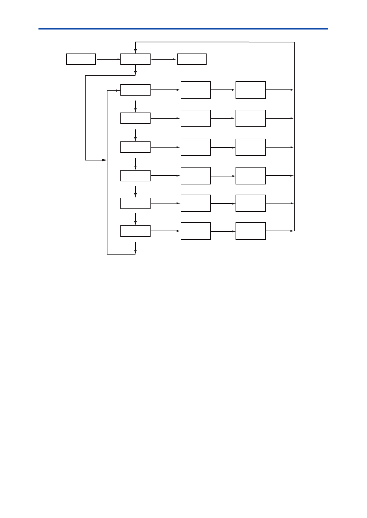
<5. DENSITY / PARAMETER SETTING>
1
*
*CAL.DT
[NO]
*ALARM
[YES]
[NO]
*SERVC
5-15
*DENS
(Physical density)
[NO]
*C_DNS
(Compensated density)
[NO]
*SP_GR
(Specific gravity)
2
*
(Molecular weight)
(Concentration)
*1: See "Figure 5.3 Process at the Setting Level" on page 5-10.
*2: The display shows the previous parameter first.
[NO]
*CALRY
(Calorific value)
[NO]
*MOL
[NO]
*CONCT
[NO]
[YES]
[YES]
[YES]
[YES]
[YES]
[YES]
XX.XXXX
*L_DNS
X.XXXX
*L_CP.D
X.XXXX
*L_SPC
XXX.XXX
*L_CAL
XXX.XX
*L_MOL
XXX.X
*L_CON
[ENT]
[ENT]
[ENT]
[ENT]
[ENT]
[ENT]
XX.XXXX
*H_DNS
X.XXXX
*H_CP.D
X.XXXX
*H_SPC
XXX.XXX
*H_CAL
XXX.XX
*H_MOL
XXX.X
*H_CON
[ENT]
[ENT]
[ENT]
[ENT]
[ENT]
[ENT]
F0506.ai
Figure 5.5 Process of the Alarm-point Setting Mode
IM 11T3E1-01E
Page 71
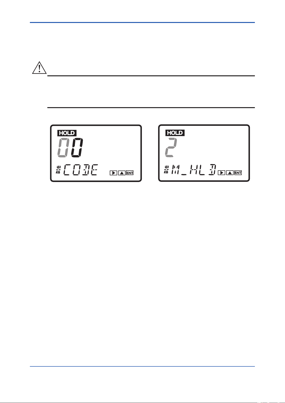
<5. DENSITY / PARAMETER SETTING>
5.2.3 Parameter Setting at Service Level
To move to the service level, select [*SERVC] at the setting level, and press the [YES] key. (see
Figure 5.3 on page 5-10.) The main task at the setting level is to set data values such as a measuring range. To go into each mode of the service level, enter the appropriate code number.
CAUTION
DO NOT enter codes other than those listed in Table 5.4. A change to the settings of any unlisted
code can result in the failure of the analyzer to operate properly. If you have entered a wrong code
number by mistake, press the [MODE] key to return to the measurement mode(<MEASURE>).
You may exit the mode of that wrong code by pressing the [ENT] key, if you haven't made any
change to the relevant data.
(1) (2)
5-16
When [*SERVC] is shown on the display, press
[YES] key. The message field changes to look
like the one shown left.
Figure 5.6 Entry of Code Number at Service Level
Press the [ENT] key with code number 01 shown
on the display, for example. The analyzer enters
the mode for setting the parameters of that code.
The following explains the parameter setting procedures in the order of code numbers.
F0507.ai
IM 11T3E1-01E
Page 72
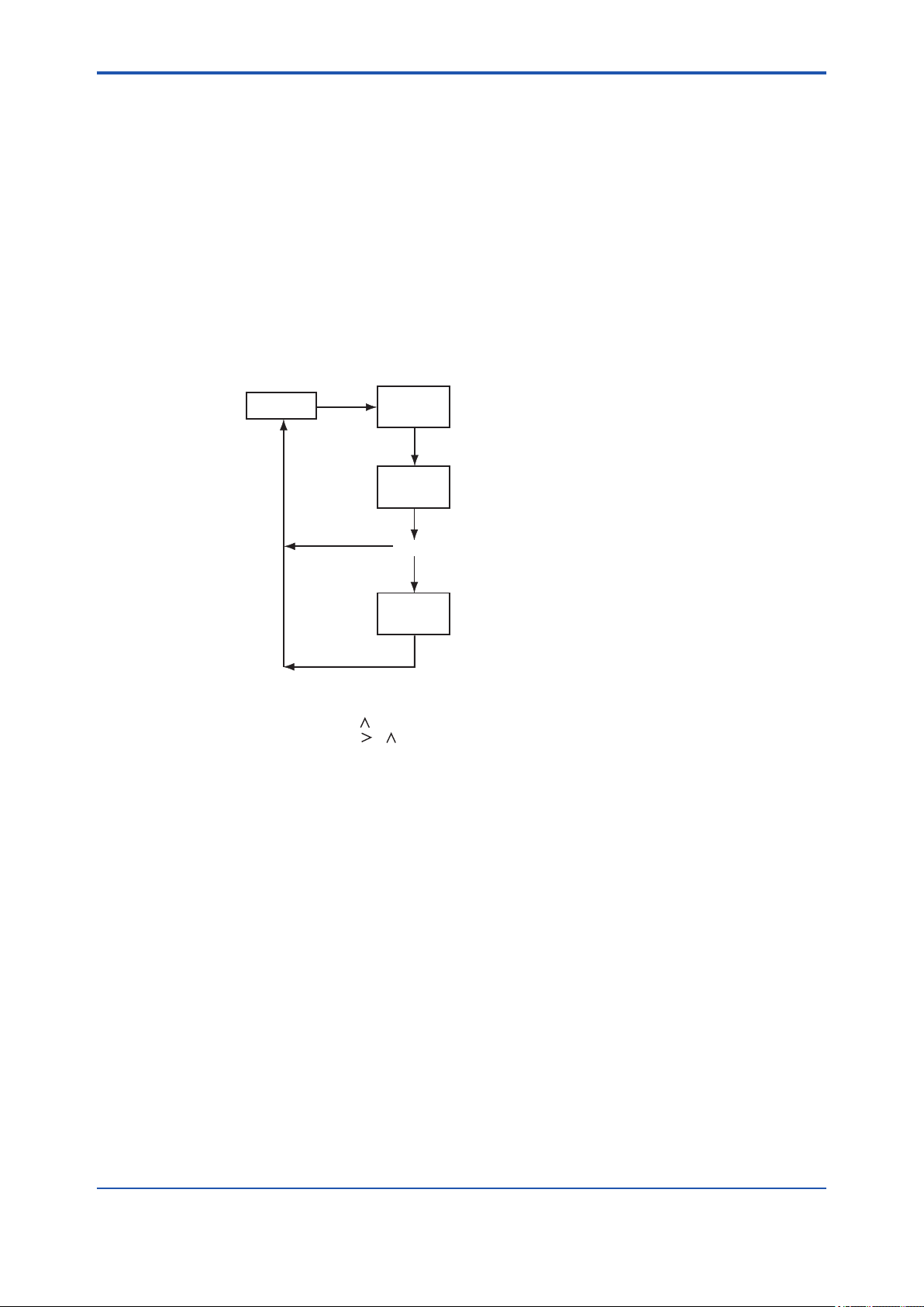
<5. DENSITY / PARAMETER SETTING>
CODE 01: Setting of Hold during Maintenance
This setting determines whether or not the output signal is held during maintenance. As a value
to be held, you can select either a value immediately before or a preset value.
(a) Hold enable/disable [*M_HLD]
・ Disable: 0
・ Enable: 1
・ Enable (preset value): 2
(b) Setting of preset hold value [*PR.SET]
This item applies if item (a) above is set to "2".
Congurable range: -10.0 to 110.0 (percent of analog output)
1
*
*SERVC
[YES]
01
*CODE
[ENT]
2
*
5-17
X
*M_HLD
5
*
[ENT]
XXX.X
*PR.SET
[ENT]
*1: See "Figure 5.3 Process at the Setting Level" on page 5-10.
*2: Enter the code number.
*3: Set a value using the [ ] and [ENT] keys.
*4: Set a value using the [ ], [ ] and [ENT] keys.
If you enter a value that exceeds the limits, the display shows [*OVER].
Press the [YES] or [NO] key to re-set the value.
*5: Setting 0 or 1 returns to the service level with the indication [*SERVC].
Figure 5.7 Setting of Hold during Maintenance
3
*
4
*
F0508.ai
IM 11T3E1-01E
Page 73

<5. DENSITY / PARAMETER SETTING>
*
1
CODE 02: Setting of Hold in the Event of Error
This setting determines whether or not the output signal is held if an error occurs. You can select
either the value immediately prior to the error or a preset value as the value to be held.
(a) Hold enable/disable [*E_HLD]
・Disable: 0
・Enable: 1
・Enable (preset value): 2
(b) Setting of preset hold value [*PR.SET]
This item applies if item (a) above is set to "2".
Congurable range: -10.0 to 110.0 (percent of analog output)
1
*
*SERVC
[YES]
02
*CODE
[ENT]
2
*
5-18
X
*E_HLD
5
*
[ENT]
XXX.X
*PR.SET
*1: See "Figure 5.3 Process at the Setting Level" on page 5-10.
*2: Enter the code number.
*3: Set a value using the [ ] and [ENT] keys.
*4: Set a value using the [ ], [ ] and [ENT] keys.
If you enter a value that exceeds the limits, the display shows [*OVER].
Press the [YES] or [NO] key to re-set the value.
*5: Setting 0 or 1 returns to the service level with the indication [*SERVC].
[ENT]
3
*
4
*
F0509.ai
Figure 5.8 Setting of Hold in the Event of Error
CODE 04: Setting of Output-smoothing Constants [*SMOTH]
This setting denes the constants for output smoothing. This smoothing constants is outputsmoothing constants of converter (electrical circuit boards).
Congurable range: 00 to 60 (unit : second)
*SERVC
*1: See "Figure 5.3 Process at the Setting Level" on page 5-10.
*2: Enter the code number.
*3: Set a value using the [ ], [ ] and [ENT] keys.
If you enter a value that exceeds the limits, the display shows [*OVER].
Press the [YES] or [NO] key to re-set the value.
[YES]
04
*CODE
XX
*SMOTH
[ENT]
[ENT]
2
*
3
*
F0510.ai
Figure 5.9 Setting of Output-smoothing Constants
IM 11T3E1-01E
Page 74
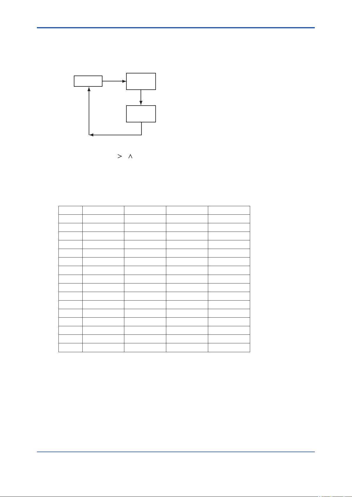
<5. DENSITY / PARAMETER SETTING>
CODE 05: Setting of Contact Outputs Status [*CNTCT]
This setting denes the status of the contact outputs.
Congurable range: 00 to 15
1
*
*SERVC
[YES]
05
*CODE
[ENT]
2
*
5-19
XX
*CNTCT
*1: See "Figure 5.3 Process at the Setting Level" on page 5-10.
*2: Enter the code number.
*3: Set a value using the [ ], [ ] and [ENT] keys.
If you enter a value that exceeds the limits, the display shows [*OVER].
Press the [YES] or [NO] key to re-set the value.
Figure 5.10 Setting of Contact Outputs Status
[ENT]
3
*
F0511.ai
Each contact output takes either of the following two status (in table), depending on the value you
set.
Value ZERO contact SPAN contact MAINT contact ALM contact
0 NO NO NO NO
1 NO NO NO NC
2 NO NO NC NO
3 NO NO NC NC
4 NO NC NO NO
5 NO NC NO NC
6 NO NC NC NO
7 NO NC NC NC
8 NC NO NO NO
9 NC NO NO NC
10 NC NO NC NO
11 NC NO NC NC
12 NC NC NO NO
13 NC NC NO NC
14 NC NC NC NO
15 NC NC NC NC
NO: means “normally open”
NC: means “normally closed”
IM 11T3E1-01E
Page 75
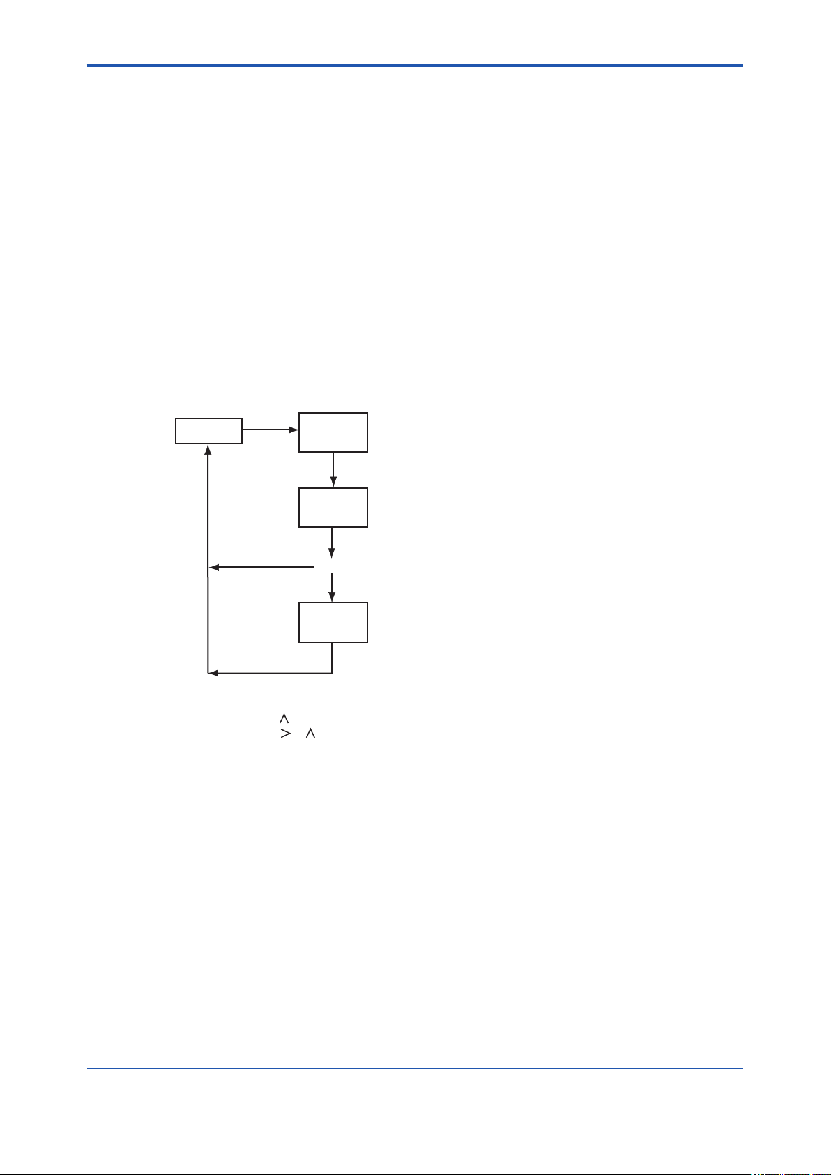
<5. DENSITY / PARAMETER SETTING>
CODE 10: Setting of Pressure Compensation
This setting determines whether or not the measured density should be compensated by the gas
pressure. The density can be compensated to either the value immediately before the error or a
xed value.
(a) Enable/disable/xed value [*P.COMP]
・Disable: 0
・Enable (value immediately before): 1
・Enable (xed value): 2
(b) Setting of xed value for pressure compensation [*P.FIX]
This item applies if item (a) above is set to "2".
Congurable range: 0.10 to 999.99 (for kPa),
0.0001 to 9.9999 (for MPa),
0.015 to 99.999 (for psi )
1
*
*SERVC
[YES]
10
*CODE
2
*
5-20
[ENT]
X
*P.COMP
5
*
[ENT]
XXX.XX
*P.FIX
*1: See "Figure 5.3 Process at the Setting Level" on page 5-10.
*2: Enter the code number.
*3: Set a value using the [ ] and [ENT] keys.
*4: Set a value using the [ ], [ ] and [ENT] keys.
If you enter a value that exceeds the limits, the display shows [*OVER].
Press the [YES] or [NO] key to re-set the value.
*5: Setting 0 or 1 returns to the service level with the indication [*SERVC].
*6: The position of the decimal point changes depending on the setting of CODE 20.
If the code is set to "0" (kPa), the reading is XXX.XX;
if the code is set to "1" (MPa), the reading is X.XXXX;
if the code is set to "2" (psi), the reading is XX.XXX.
Figure 5.11 Setting of Pressure Compensation
[ENT]
3
*
6
*
4
*
F0512.ai
IM 11T3E1-01E
Page 76

<5. DENSITY / PARAMETER SETTING>
CODE 11: Setting for Compensated Density Measurement
This setting denes the reference temperature and pressure required to obtain the compensated
density.
(a) Setting of reference temperature [*C.D.TMP]
Congurable range: -20.0 to 80.0 (for °C)
-4.0 to 176.0 (for °F )
(b) Setting of reference pressure [*C.D.PRS]
Congurable range: 0.10 to 999.99 (for kPa),
0.0001 to 9.9999 (for MPa),
0.015 to 99.999 (for psi )
1
*
*SERVC
[YES]
11
*CODE
[ENT]
2
*
5-21
[ENT]
[ENT]
4
*
3
*
5
*
3
*
F0513.ai
XX.X
*C.D.TMP
XXX.XX
*C.D.PRS
*1: See "Figure 5.3 Process at the Setting Level" on page 5-10.
*2: Enter the code number.
*3: Set a value using the [ ], [ ] and [ENT] keys.
If you enter a value that exceeds the limits, the display shows [*OVER].
Press the [YES] or [NO] key to re-set the value.
*4: The position of the decimal point changes depending on the setting of CODE 23.
If the code is set to "0" (°C), the reading is XX.X;
if the code is set to "1" (°F), the reading is XXX.X.
*5: The position of the decimal point changes depending on the setting of CODE 20.
If the code is set to "0" (kPa), the reading is XXX.XX;
if the code is set to "1" (MPa), the reading is X.XXXX;
if the code is set to "2" (psi), the reading is XX.XXX.
Figure 5.12 Setting for Compensated Density Measurement
IM 11T3E1-01E
Page 77

<5. DENSITY / PARAMETER SETTING>
CODE 12: Setting of Gas Pressure
This setting denes the zero and span points of the pressure transmitter's measurement range.
(a) Setting of zero-point gas pressure [*Z_PRS]
Congurable range: 0.01 to 999.99 (for kPa),
0.0001 to 9.9999 (for MPa),
0.015 to 99.999 (for psi )
(b) Setting of span-point gas pressure [*S_PRS]
Congurable range: 0.10 to 999.99 (for kPa),
0.0001 to 9.9999 (for MPa),
0.015 to 99.999 (for psi )
The zero and span points set here are also used for the analog output.
1
*
*SERVC
[YES]
12
*CODE
[ENT]
2
*
5-22
[ENT]
[ENT]
4
*
3
*
4
*
3
*
F0514.ai
XXX.XX
*Z_PRS
XXX.XX
*S_PRS
*1: See "Figure 5.3 Process at the Setting Level" on page 5-10.
*2: Enter the code number.
*3: Set a value using the [ ], [ ] and [ENT] keys.
If you enter a value that exceeds the limits, the display shows [*OVER].
Press the [YES] or [NO] key to re-set the value.
*4: The position of the decimal point changes depending on the setting of CODE 20.
If the code is set to "0" (kPa), the reading is XXX.XX;
if the code is set to "1" (MPa), the reading is X.XXXX;
if the code is set to "2" (psi), the reading is XX.XXX.
Figure 5.13 Setting of Gas Pressure
IM 11T3E1-01E
Page 78

<5. DENSITY / PARAMETER SETTING>
CODE 13: Selection for Automatic Calibration [*AUTO.C]
This setting determines whether or not automatic calibration is carried out. If automatic calibration
is to be carried out, you must also congure CODE 15 at the service level.
・ Disable: 0
・ Enable: 1
5-23
.
*1: See "Figure 5.3 Process at the Setting Level" on page 5-10.
*2: Enter the code number.
*3: Set a value using the [ ], [ ] and [ENT] keys.
Figure 5.14 Selection for Automatic Calibration
1
*
*SERVC
[YES]
13
*CODE
[ENT]
X
*AUTO.C
[ENT]
2
*
3
*
F0515.ai
CODE 14: Setting for Remote Semi-automatic Calibration [*REMOT]
This setting determines whether or not semi-automatic calibration is carried out remotely.
If remote semi-automatic calibration is to be carried out, you must wire the contact input.
You must also congure CODE 15 at the service level.
・ Disable: 0 (The contact is open)
・ Enable: 1 (The contact is closed)
.
*1: See "Figure 5.3 Process at the Setting Level" on page 5-10.
*2: Enter the code number.
*3: Set a value using the [ ], [ ] and [ENT] keys.
Figure 5.15 Setting for Remote Semi-automatic Calibration
1
*
*SERVC
[YES]
14
*CODE
X
*REMOT
[ENT]
[ENT]
2
*
3
*
F0516.ai
IM 11T3E1-01E
Page 79

<5. DENSITY / PARAMETER SETTING>
CODE 15: Setting of Data for Automatic/Semi-automatic Calibration
This setting denes the data needed to carry out automatic/semi-automatic calibration.
(a) Selection of calibration item [*CAL.P]
・ Zero and span: 0
・ Zero: 1
・ Span: 2
(b) Setting of calibration time [*CAL.T]
Congurable range: 00 to 60 (unit : minute)
(c) Setting of stabilization time [*STAB.T]
Congurable range: 00 to 60 (unit : minute)
(d) Setting of calibration starting time
(1) Setting of year/month/day [*Y_M_D]
Congurable range: 00.01.01 to 99.12.31
(2) Setting of hour/minute [*H_M]
Congurable range: 00.00 to 23.59
5-24
(e) Selection of unit of calibration interval [*CYCL.U]
・ Hour: 0
・ Day: 1
(f) Selection of calibration interval [*CYCL.T]
Item (e) above is set to "0".
Congurable range: 00 to 23 (for hour)
Item (e) above is set to "1".
Congurable range: 000 to 255 (for day)
For more information, see Chapter 8, “Calibration Procedure”.
IM 11T3E1-01E
Page 80
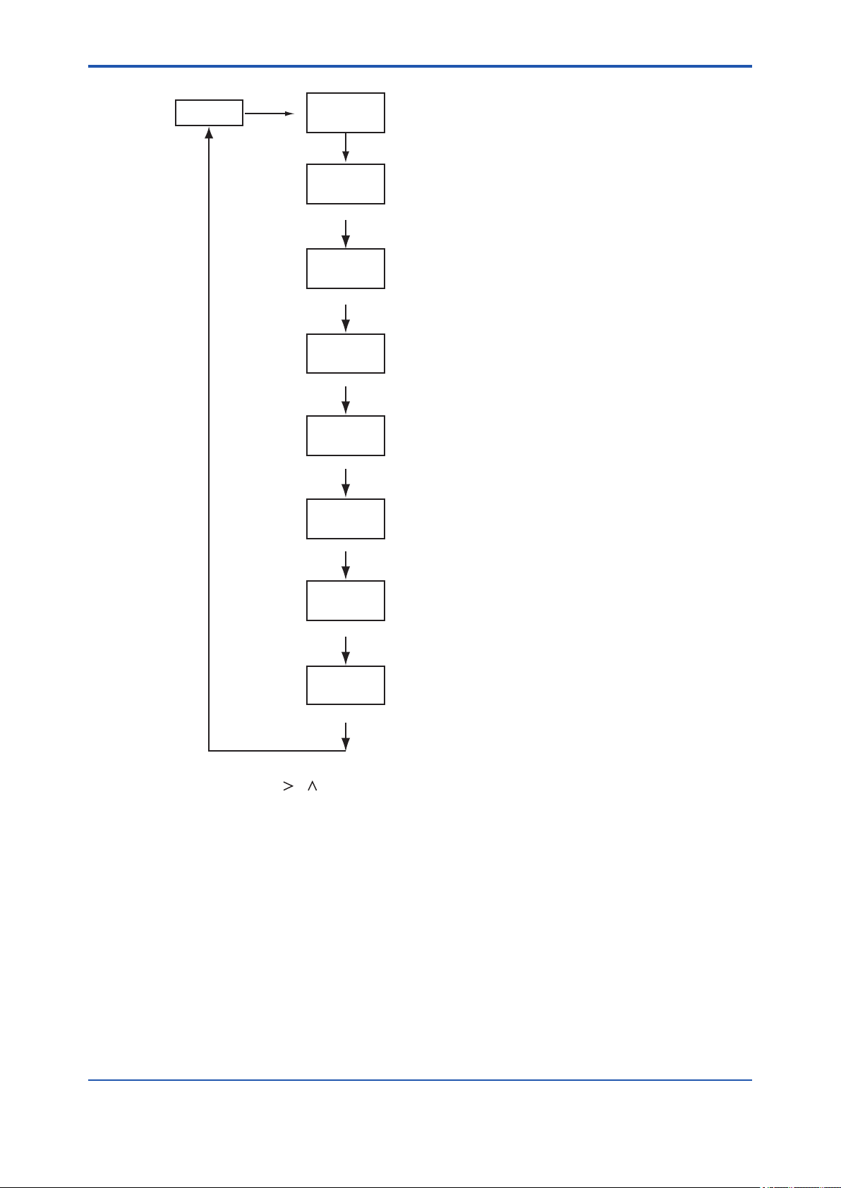
<5. DENSITY / PARAMETER SETTING>
1
*
*SERVC
[YES]
15
*CODE
[ENT]
2
*
X
*CAL.P
(Selection of calibration item)
[ENT]
2
*
XX
[ENT]
2
*
*CAL.T
(Setting of calibration time)
XX
[ENT]
2
*
*STAB.T
(Setting of stabilization time)
XX.XX.XX
*Y_M_D
(Setting of calibration starting time [year/ month/ day])
[ENT]
2
*
5-25
XX.XX
[ENT]
2
*
*H_M
(Setting of calibration starting time [hour/ minute])
X
*CYCL.U
(Selection of unit of calibration interval)
XXX
*CYCL.T
(Selection of calibration interval)
*1: See "Figure 5.3 Process at the Setting Level" on page 5-10.
*2: Set a value using the [ ], [ ] and [ENT] keys.
If you enter a value that exceeds the limits, the display shows [*OVER].
Press the [YES] or [NO] key to re-set the value.
*3: The number of digits on LCD varies depending on the unit of the calibration interval (parameter [*CYCL.U]).
If the parameter is set to "0" (hour), the indication is two-digit number.
If the parameter is set to "1" (day), the indication is three-digit number.
Figure 5.16 Setting of Data for Automatic/Semi-automatic Calibration
[ENT]
[ENT]
2
*
3
*
2
*
F0517.ai
IM 11T3E1-01E
Page 81
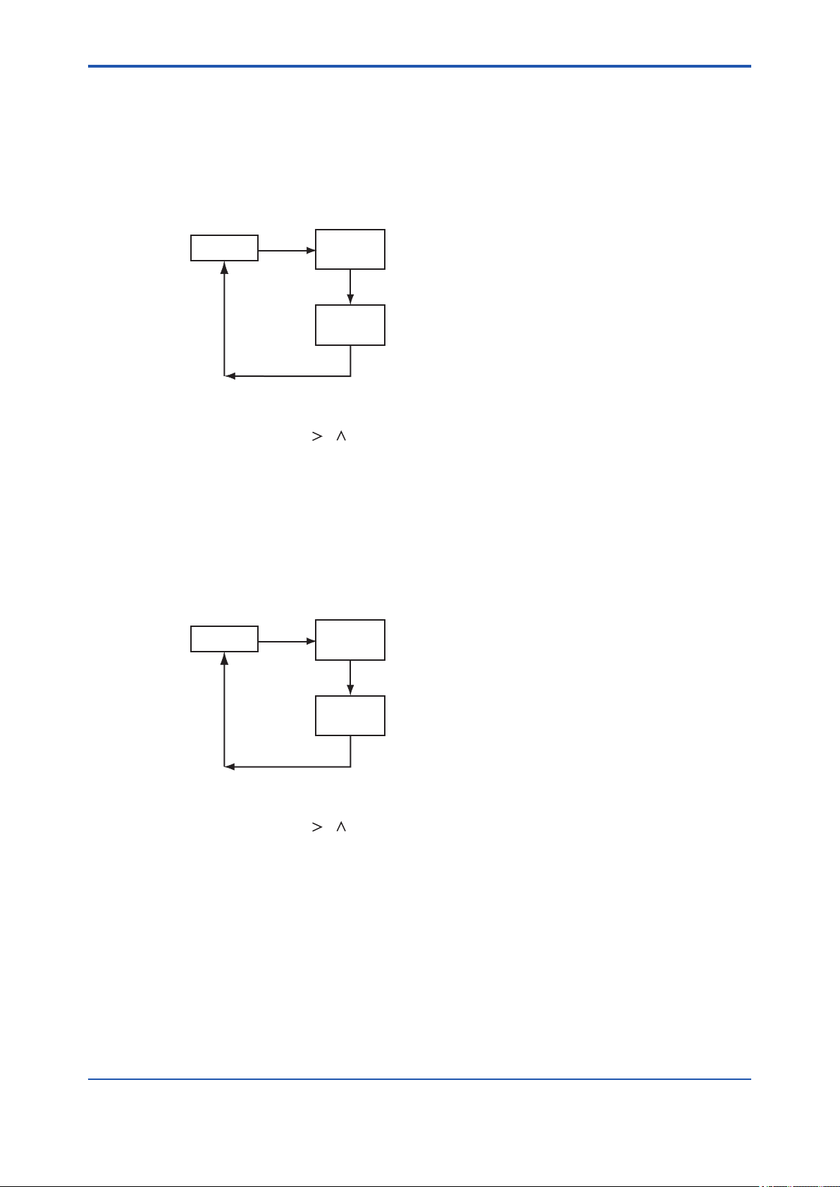
<5. DENSITY / PARAMETER SETTING>
CODE 20: Selection of Pressure Unit [*PRES.U]
This setting denes the pressure unit for the gas pressure transmitter.
・ kPa: 0
・ MPa: 1
・ psi : 2
1
*
*SERVC
[YES]
20
*CODE
[ENT]
2
*
5-26
X
*PRES.U
*1: See "Figure 5.3 Process at the Setting Level" on page 5-10.
*2: Enter the code number.
*3: Set a value using the [ ], [ ] and [ENT] keys.
Figure 5.17 Selection of Pressure Unit.
[ENT]
3
*
F0518.ai
CODE 21: Selection of Density Unit [*DENS.U]
This setting denes the density unit for the gas density meter.
・ kg/m3: 0
・ lb/ft3: 1
1
*
*SERVC
[YES]
21
*CODE
[ENT]
X
*DENS.U
2
*
3
*
[ENT]
*1: See "Figure 5.3 Process at the Setting Level" on page 5-10.
*2: Enter the code number.
*3: Set a value using the [ ], [ ] and [ENT] keys.
Figure 5.18 Selection of Density Unit
F0519.ai
IM 11T3E1-01E
Page 82

<5. DENSITY / PARAMETER SETTING>
CODE 22: Selection of Caloric Value Unit [ *CAL.U]
This setting denes the caloric value unit for the gas density meter.
• MJ/m3 : 0
• kBTU/ft3 : 1
1
*
*SERVC
[YES]
22
*CODE
[ENT]
2
*
5-27
X
*CAL.U
*1: See "Figure 5.3 Process at the Setting Level" on page 5-10.
*2: Enter the code number.
*3: Set a value using the [ ], [ ] and [ENT] keys.
Figure 5.19 Selection of Caloric Value Unit
[ENT]
3
*
F0520.ai
CODE 23: Selection of Temperature Unit [ *TEMP.U]
This setting denes the temperature unit for the gas density meter.
• °C: 0
• °F: 1
1
*
*SERVC
[YES]
23
*CODE
[ENT]
X
*TEMP.U
2
*
3
*
[ENT]
*1: See "Figure 5.3 Process at the Setting Level" on page 5-10.
*2: Enter the code number.
*3: Set a value using the [ ], [ ] and [ENT] keys.
Figure 5.20 Selection of Temperature Unit
F0521.ai
IM 11T3E1-01E
Page 83
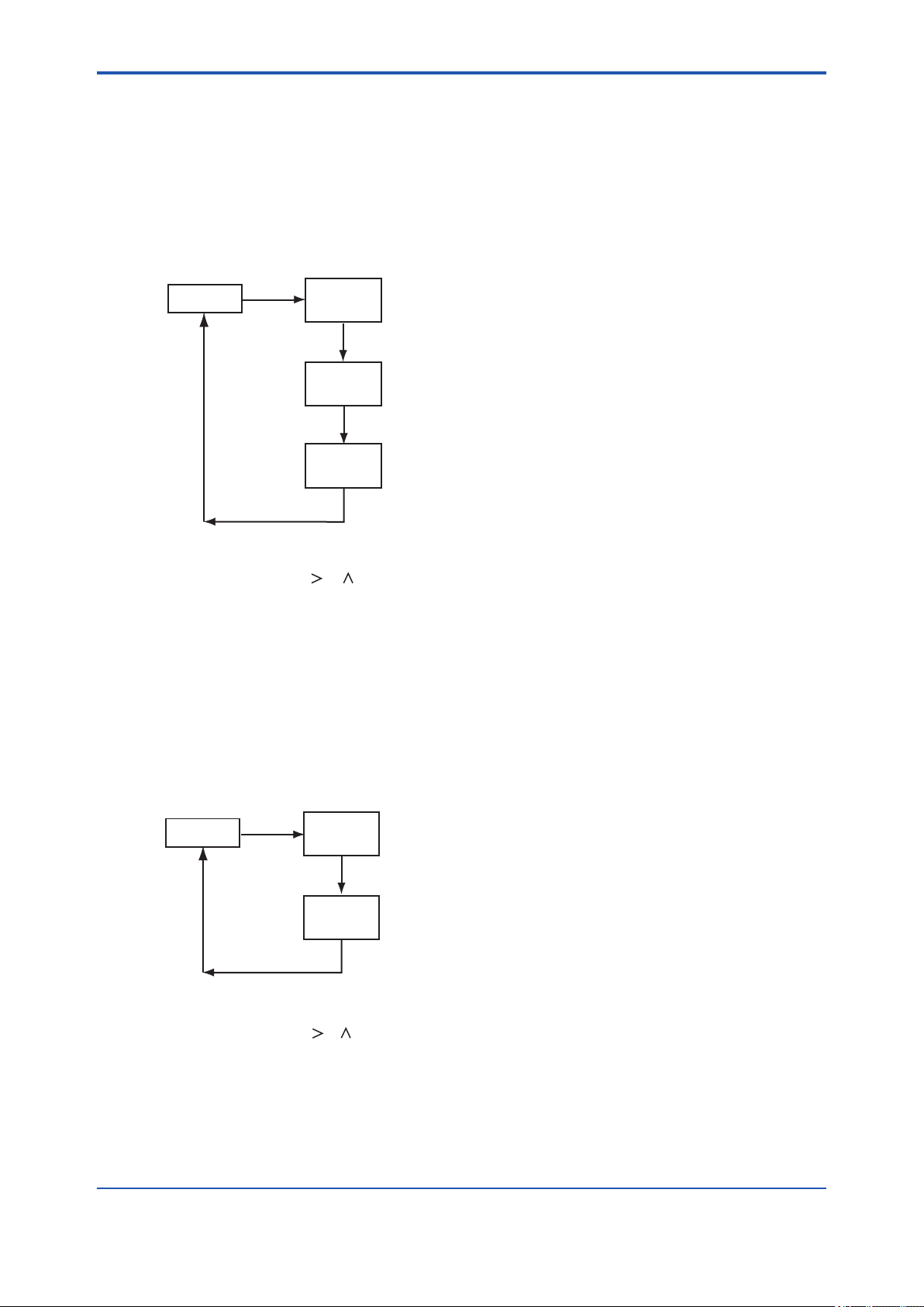
<5. DENSITY / PARAMETER SETTING>
CODE 30: Setting of Calendar
This setting denes the date and time.
(a) Setting of year/month/day [*Y_M_D]
Congurable range : 00.01.01 to 99.12.31
(b) Setting of hour/minute [*H_M]
Congurable range : 00.00 to 23.59
1
*
*SERVC
[YES]
30
*CODE
[ENT]
2
*
5-28
XX.XX.XX
*Y_M_D
XX.XX
*H_M
*1: See "Figure 5.3 Process at the Setting Level" on page 5-10.
*2: Enter the code number.
*3: Set a value using the [ ], [ ] and [ENT] keys.
If you enter a value that exceeds the limits, the display shows [*OVER].
Press the [YES] or [NO] key to re-set the value.
Figure 5.21 Setting of Calendar
[ENT]
[ENT]
3
*
3
*
F0522.ai
CODE 31: Showing/Hiding of Negative Measured Values [*MINUS]
This setting determines whether negative measured values (-) should be shown or hidden.
・ Show: 0
・ Hide: 1
1
*
*SERVC
[YES]
31
*CODE
2
*
[ENT]
X
*MINUS
*1: See "Figure 5.3 Process at the Setting Level" on page 5-10.
*2: Enter the code number.
*3: Set a value using the [ ], [ ] and [ENT] keys.
Figure 5.22 Showing/Hiding of Negative Measured Values
[ENT]
3
*
F0523.ai
IM 11T3E1-01E
Page 84

<5. DENSITY / PARAMETER SETTING>
CODE 40: Indication of Calibration Coefcients (Read-only)
This setting determines the calibration coefcients to be indicated.
(a) Zero [*C_K_Z]: indicated as SX.XXXX
(b) Span [*C_K_S]: indicated as X.XXXX
1
*
*SERVC
[YES]
40
*CODE
[ENT]
2
*
5-29
SX.XXXX
*C_K_Z
[ENT]
3
*
X.XXXX
*C_K_S
[ENT]
*1: See "Figure 5.3 Process at the Setting Level" on page 5-10.
*2: Enter the code number.
*3: By pressing the [ENT] key, the next indication is displayed.
This parameter does not accept the [ ] and [ ] key input.
Figure 5.23 Indication of Calibration Coefcients
F0524.ai
CODE 41: Indication of Oscillation Frequency (Read-only)
This setting determines the F2 and F4 oscillation frequencies coefcients to be indicated.
(a) Indication of frequency F2 (kHz) [*F2.KHZ]: indicated as X.XXXXX
(b) Indication of frequency F4 (kHz) [*F4.KHZ]: indicated as X.XXXXX
(c) Indication of frequency ratio (kHz) [*F2/F4]: indicated as X.XXXXX
1
*
*SERVC
*1: See "Figure 5.3 Process at the Setting Level" on page 5-10.
*2: Enter the code number.
*3: By pressing the [ENT] key, the next indication is displayed.
This parameter does not accept the [ ] and [ ] key input.
Figure 5.24 Indication of Oscillation Frequency
[YES]
41
*CODE
X.XXXXX
*F2.KHZ
X.XXXXX
*F4.KHZ
X.XXXXX
*F2/F4
[ENT]
[ENT]
[ENT]
[ENT]
2
*
3
*
3
*
3
*
F0525.ai
IM 11T3E1-01E
Page 85

<5. DENSITY / PARAMETER SETTING>
CODE 42: Indication of Software Version [*REV] (Read-only)
This setting allows the software version to be conrmed (indicated).
Indicated as X.XX
1
*
*SERVC
[YES]
42
*CODE
[ENT]
2
*
5-30
X.XX
*REV
*1: See "Figure 5.3 Process at the Setting Level" on page 5-10.
*2: Enter the code number.
*3: Pressing the [ENT] key returns to the service level with the indication [*SERVC].
This parameter does not accept the [ ] and [ ] key input.
Figure 5.25 Indication of Software Version
[ENT]
3
*
F0526.ai
CODE 43: Setting of High-resolution Mode [*S_CYC]
This setting selects between the normal mode and the high-resolution mode.
・ Normal mode: 0
・ High-resolution mode: 1
1
*
*SERVC
[YES]
43
*CODE
[ENT]
2
*
X
*S_CYC
*1: See "Figure 5.3 Process at the Setting Level" on page 5-10.
*2: Enter the code number.
*3: Set a value by using the [ ] and [ ] key.
Figure 5.26 Setting of High-resolution Mode
[ENT]
3
*
F0527.ai
IM 11T3E1-01E
Page 86
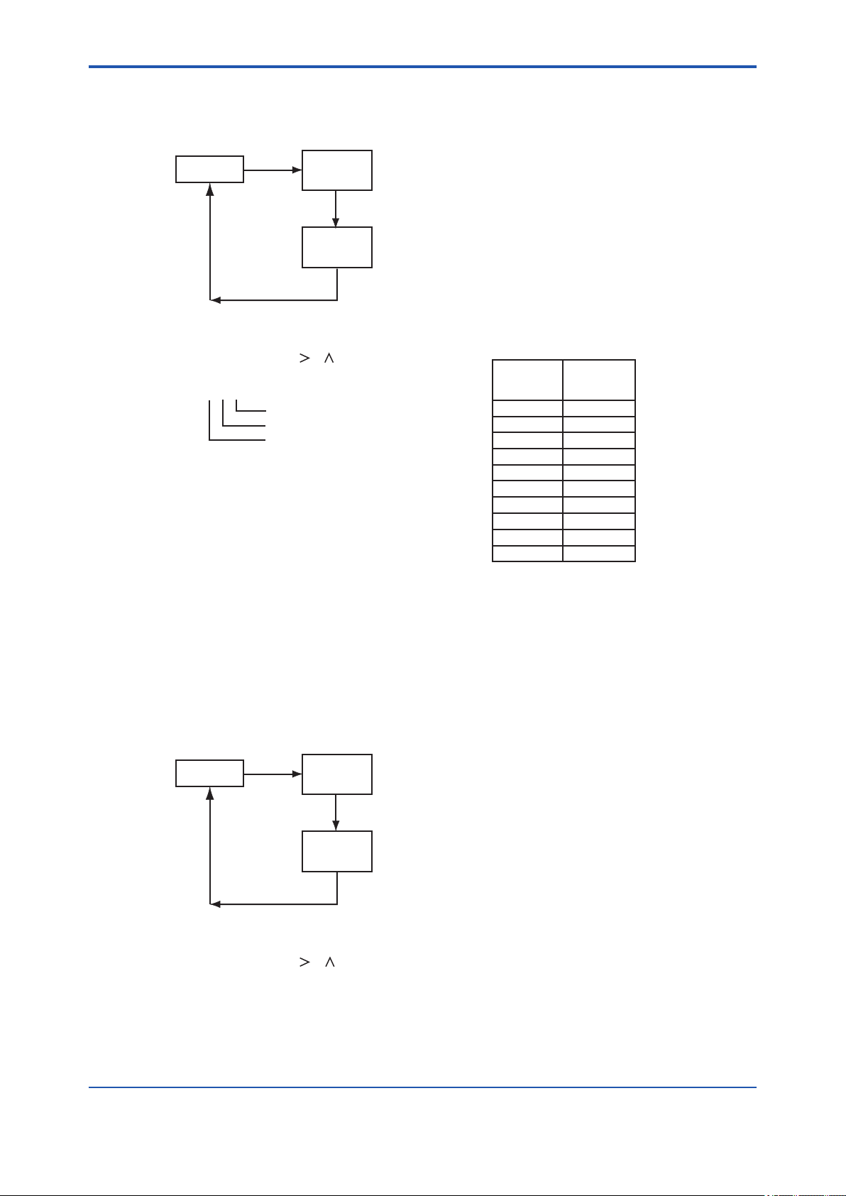
<5. DENSITY / PARAMETER SETTING>
CODE 44: Setting of PASSWORD [ *PASS]
This setting denes the password.
1
*
*SERVC
[YES]
44
*CODE
[ENT]
2
*
5-31
X.X.X
*PASS
3
*
[ENT]
F0528.ai
*1: See "Figure 5.3 Process at the Setting Level" on page 5-10.
*2: Enter the code number.
*3: Set a value by using the [ ], [ ] and [ENT] keys.
X
X.X.X
Service level
Setting level
Operation level
Note: Password entry request ( if a password is set)
At the operation level, a request is issued when the
[MODE] key is pressed in the measurement mode. At the
setting level, it is issued when the [ * ] key is pressed. At
the service level, it is issued when the [YES] key is
pressed with [*SERVC] displayed.
(Setting)
(0)
Figure 5.27 Setting of Password
CODE 45: Selecting Battery alarm detection [ *BAT]
1
2
3
4
5
6
7
8
9
Password
Contents
(No setting)
111
333
777
888
123
957
331
546
847
This setting determines whether or not battery alarm is detection.
・ Non detection: 0
・ Detection: 1
1
*
*SERVC
*1: See "Figure 5.3 Process at the Setting Level" on page 5-10.
*2: Enter the code number.
*3: Set a value by using the [ ], [ ] and [ENT] keys.
Figure 5.28 Selecting Battery alarm detection
[YES]
45
*CODE
[ENT]
X
*BAT
[ENT]
2
*
3
*
F0529.ai
IM 11T3E1-01E
Page 87

<5. DENSITY / PARAMETER SETTING>
CODE 50: Selecting the instruments [ *MODEL]
This setting denes the model.
・ Density meter: 0
・ Calorie meter: 1
・ Hydrogen purity, replacement meter : 2
1
*
*SERVC
[YES]
50
*CODE
[ENT]
2
*
5-32
X
*MODEL
*1: See "Figure 5.3 Process at the Setting Level" on page 5-10.
*2: Enter the code number.
*3: Set a value by using the [ ], [ ] and [ENT] keys.
Figure 5.29 Selecting the instruments
[ENT]
3
*
F0530.ai
CODE 82: Setting Detector Constant
This setting denes the detector constant.
CAUTION
The instruments may not only work improperly but also big problems occur unless the detector
constants entered incorrectly. Do carefully and precisely when enter the detector constants into
converter.
1. The GD402 gas density meter is shipped after adjusting the detector and converter in pairs.
When installation, conrm the converter serial number described on the label of detector so
that combines converter and detector correctly. If mismatched in pairs, converter may be out
of order. If combined correctly, no need to enter the detector constants again, as converter
has been adjusted with the constants in factory.
2. When supply converter or detector individually, enter the detector constants, described on
inside the lid of the GD40, into the converter so that the GD402 is going to be well.
IM 11T3E1-01E
Page 88

<5. DENSITY / PARAMETER SETTING>
5-33
* 1
*SERVC
[YES]
82
*CODE
[ENT]
020
*PASSW
[ENT]
XXXX
*K_A_H
[ENT]
XXXX
*K_A_L
[ENT]
XXXX
*K_B_H
[ENT]
XXXX
*K_B_L
[ENT]
XXXX
*K_C_H
[ENT]
XXXX
*K_C_L
[ENT]
XXXX
*K_AH.H
[ENT]
XXXX
*K_AH.L
[ENT]
XXXX
*K_BH.H
[ENT]
XXXX
*K_BH.L
[ENT]
XXXX
*K_CH.H
[ENT]
XXXX
*K_CH.L
[ENT]
XXXX
*T1L_H
[ENT]
XXXX
*T1L_L
[ENT]
* 2
* 4
* 3
* 3
* 3
* 3
* 3
* 3
* 3
* 3
* 3
* 3
* 3
* 3
* 3
* 3
XXXX
*T2L_H
[ENT]
XXXX
*T2L_L
[ENT]
XXXX
*T3L_H
[ENT]
XXXX
*T3L_L
[ENT]
XXXX
*T1H_H
[ENT]
XXXX
*T1H_L
[ENT]
XXXX
*T2H_H
[ENT]
XXXX
*T2H_L
[ENT]
XXXX
*T3H_H
[ENT]
XXXX
*T3H_L
[ENT]
XX.XX
*M_T1
[ENT]
XX.XX
*M_T2
[ENT]
XX.XX
*C_T
[ENT]
XX.XXX
*TMP_Z
[ENT]
XX.XXX
*TMP_S
[ENT]
* 3
* 3
* 3
* 3
* 3
* 3
* 3
* 3
* 3
* 3
* 3
* 3
* 3
* 3
* 3
*1: See "Figure 5.3 Process at the Setting Level" on page 5-10.
*2: Enter the code number.
*3: Set a value using the [ ], [ ] and [ENT] keys.
Detector Constants are described inside the lid of detector GD40.
*4: Set the PASSWORD.
Figure 5.30 Setting Detector Constant
F0531.ai
IM 11T3E1-01E
Page 89

Blank Page
Page 90

<6. CALORIE / PARAMETER SETTING>
6. CALORIE / PARAMETER SETTING
CAUTION
Password is not selected in rst condition. When password is necessary, refer to Section “4.2
Setting Lists”.
This chapter describes how to set parameters of Calorie meter.
If select Density meter, see Chapter 5.
If select Hydrogen purity meter, see Chapter 7.
Conversion Table
1 lb/ft3 = 16.01847 kg/m
1 kBTU/ft3 = 37.25901232 MJ/m
X degF = (X-32)/1.8
1 psi = 6.894756794 kPa
Density of Air = 1.2928 kg/m
= 0.08070684 lb/ft
3
3
3
3
6-1
IM 11T3E1-01E
Page 91

<6. CALORIE / PARAMETER SETTING>
6.1 Setting Parameters
Subsections 6.1.1 to 6.1.4 show the setting parameters for each level.
6.1.1 Setting Parameters at Measurement Level
When turned on, the analyzer starts up in the measurement mode (<MEASURE>).
Table 6.1 Setting Parameters at Measurement Level
6-2
Mode/Setting parameter Display
Measurement mode
Indication of measurement value
Physical density
Compensated density
Caloric value
Indication of message
Unit
Error symbol and number
Alarm mark and number
Indication of HOLD and FAIL
HOLD
FAIL
DISP mode
Physical density
Compensated density
Caloric value
Sample gas temperature
Sample gas pressure
Analog output 1 (%)
Analog output 2 (%)
KG/M3
LB/FT3
KG/M3
LB/FT3
MJ/M3
KBTU
ERR.NO
ALM.NO
HOLD
FAIL
DISP
KG/M3
LB/FT3
KG/M3
LB/FT3
MJ/M3
KBTU
ºC
ºF
KPA
MPA
PSI
MA1%
MA2%
Data to be Set
(or Conditions)
Set the unit in CODE 21.
Set the unit in CODE 21.
Set the unit in CODE 22.
Set the unit in CODE 21.
Set the unit in CODE 21.
Set the unit in CODE 22.
Set the unit in CODE 23.
Set the unit in CODE 20.
Remarks
See Figure 6.3 for key operation.
The unit is the one set in the service level.
Appears if an error occurs.
Appears if an alarm occurs.
Appears even during other modes.
Appears during a HOLD state.
Appears if a failure occurs.
See Figure 6.3 for key operation.
Selection of parameters to be measured in
the measurement mode.
Read-only
Read-only
Read-only
Read-only
IM 11T3E1-01E
Page 92

<6. CALORIE / PARAMETER SETTING>
6.1.2 Setting Parameters at Operation Level
Press the [MODE] key and enter the password (XXX) to gain access to this level (see Figure 6.1
for key operation).
Table 6.2 Setting Parameters at Operation Level
6-3
Mode/Setting parameter Display
Calibration mode
Semi-automatic calibration
Manual calibration
Setting of zero-point caloric
value
Setting of zero-point density
Setting of span-point caloric
value
Setting of span-point density
Zero/span-gas valve operation
Zero-gas valve operation
Span-gas valve operation
Sample-gas valve operation
Density/calorie conversion factor
setting mode
Automatic zero-point adjustment
Factor setting
Zero point
Factor K0
Factor K1
Data to be Set
(or Conditions)
SEM.CAL
MAN.CAL
Z_CAL
Z_DNS
S_CAL
S_DNS
VALVE No setting is required for
ADJUST
AT_ADJ
SET_K
K0_ADJ
K0
K1
One-touch calibration See Figure 9.3 for key operation.
manual
calibration.
Control of zero-gas valve
Control of span-gas
valve
Switching between sample and
calibration gases
The decimal point can
be repositioned for this
setting only.
Range : -99999 to 99999
Range : -99999 to 99999
Range : 0 to 99999
Remarks
See Figure 9.4 for key operation.
See Figure 9.1 for key operation.
See Figure 6.2 for key operation.
(Floating-point)
IM 11T3E1-01E
Page 93

<6. CALORIE / PARAMETER SETTING>
6.1.3 Setting Parameters at Setting Level
Press the [*] key and enter the password (XXX) to gain access to this level (see Figure 6.5 for key
operation).
Table 6.3 Setting Parameters at Setting Level
6-4
Mode/Setting parameter Display
Analog output setting
Output 1
Set a parameter to be output
Set the zero and span points
Physical density
Compensated density
Caloric value
Output 2 (same as output 1)
Setting calibration data
Zero-point caloric value
Zero-point density
Span-point caloric value
Span-point density
Output hold value during calibration
Setting of preset value
(Only if the preceding parameter
is set to 2 (preset value))
Alarm-point setting
Select a parameter for which an
alarm is set
Physical density
Compensated density
Caloric value
Set the high/low limits.
Physical density
Compensated density
Caloric value
*RANGE
*OUT1
*DENS
*C_DNS
*CALRY
*TEMP
*PRESS
*Z_DNS,
*S_DNS
*Z_CP.D,
*S_CP.D
*Z_CAL,
*S_CAL
*OUT2
*CAL.DT
*Z_CAL
*Z_DNS
*S_CAL
*S_DNS
*C_HLD
*PR.SET
*ALARM
*DENS
*C_DNS
*CALRY
*L_DNS,
*H_DNS
*L_CP.D,
*H_CP.D
*L_CAL,
*H_CAL
Data to be Set
(or Conditions)
Physical density
Compensated density
Caloric value
Gas temperature
Gas pressure
00.0000 to 60.0000 kg/m
0.00000 to 4.00000 lb/ft
0.0000 to 6.0000 kg/m
3
0.00000 to 0.40000 lb/ft
000.000 to 133.000 MJ/m
0.0000 to 3.5000 kBTU/ft
000.000 to 133.000 MJ/m
0.0000 to 6.0000 kg/m
3
0.00000 to 0.40000 lb/ft
000.000 to 133.000 MJ/m
0.0000 to 3.5000 kBTU/ft
0.0000 to 6.0000 kg/m
3
0.00000 to 0.40000 lb/ft
· Disable: 0
·
Enable (value
immediately before) : 1
·
Enable (preset value) : 2
-10.0 to 110.0
00.0000 to 60.0000 kg/m
0.0000 to 6.0000 kg/m
3
000.000 to 133.000 MJ/m
Remarks
See Figure 6.5 for key operation.
3
No setting is required if the parameter is
3
temperature or pressure.
3
3
3
See Figure 9.2 for key operation.
3
3
3
3
3
See Figure 6.6 for key operation.
3
3
IM 11T3E1-01E
Page 94
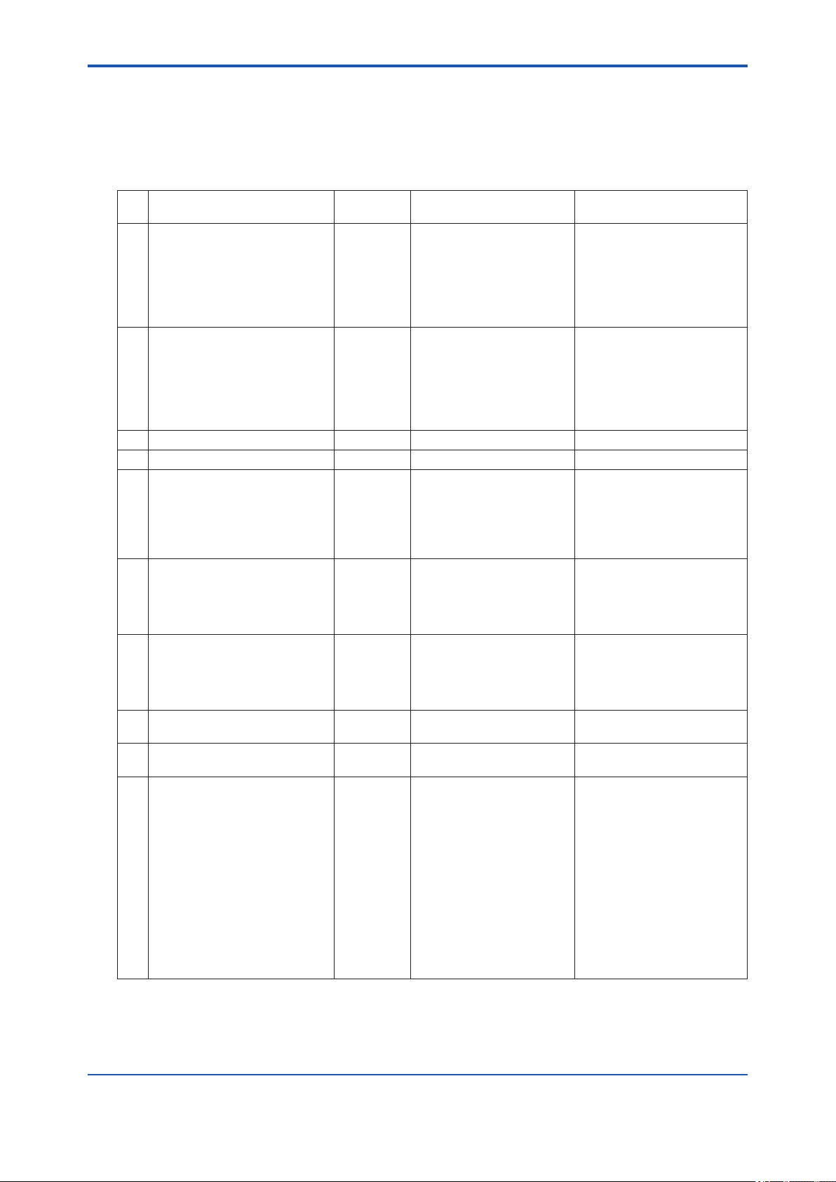
<6. CALORIE / PARAMETER SETTING>
6.1.4 Setting Parameters at Service Level
Press the [*] key and enter the password (XXX) to select the service level. When you select this
level, the analyzer shows a Code No. promptly. Type the appropriate code number and press the
[ENT] key.
Table 6.4 Setting Parameters at Service Level
Code
No.
01 Setting of hold during maintenance
Hold enable/disable
Setting of preset hold value
02 Setting of hold against errors
Hold enable/disable
Setting of preset hold value
04 Setting of output-smoothing constants *SMOTH 00 to 60 See Figure 6.10 for key operation.
05 Setting of contact outputs status *CNTCT 00 to 15 See Figure 6.11 for key operation.
10 Setting of pressure compensation
Enable/disable/xed value
Setting of xed value for pressure
compensation
11 Setting for compensated density
measurement
Setting of reference temperature
Setting of reference pressure
12 Setting of gas pressure
Setting of zero-gas pressure
Setting of span-gas pressure
13 Selection for automatic calibration *AUTO.C · Disable : 0
14 Setting for remote semi-automatic
calibration
15 Setting of data for automatic/semi-
automatic calibration
Selection of calibration item
Setting of calibration time
Setting of stabilization time
Setting of calibration starting time
Setting of year/month/day
Setting of hour/minute
Selection of unit of calibration
interval
Selection of calibration interval
Item Display
*M_HLD
*PR.SET
*E_HLD
*PR.SET
*P.COMP
*P.FIX
*C.D.TMP
*C.D.PRS
*Z_PRS
*S_PRS
*REMOT · Disable : 0
*CAL.P
*CAL.T
*STAB.T
*Y_M_D
*H_M
*CYCL.U
*CYCL.T
0.01 to 999.99kPa, 0.0001 to
9.9999MPa, 0.015 to 99.999 psi
0.10 to 999.99kPa, 0.0001 to
9.9999MPa, 0.015 to 99.999 psi
· Enable : 1
· Enable : 1
Zero and span : 0
Zero : 1
Span : 2
00 to 60
00 to 60
00.01.01 to 99.12.31
00.00 to 23.59
Hour : 0
Day : 1
Hour : 00 to 23
Day : 000 to 255
Data to be Set
(or Conditions)
· Disable : 0
· Enable (value immediately
before) : 1
· Enable (preset value) : 2
-10.0 to 110.0
· Disable : 0
· Enable (value immediately
before) : 1
· Enable (preset value) : 2
-10.0 to 110.0
· Disable: 0
· Enable (measured value) : 1
· Enable (xed value) : 2
0.10 to 999.99kPa, 0.0001 to
9.9999MPa, 0.015 to 99.999 psi
-20.0 to 80.0 °C, -4.0 to 176.0 °F
0.10 to 999.99kPa, 0.0001 to
9.9999MPa, 0.015 to 99.999 psi
Remarks
See Figure 6.8 for key operation.
If “preset value” is selected in the
preceding parameter.
See Figure 6.9 for key operation.
If “preset value” is selected in the
preceding parameter.
See Figure 6.12 for key operation.
If “xed value” is selected in the
preceding parameter.
See Figure 6.13 for key operation.
See Figure 6.14 for key operation.
See Figure 6.15 for key operation.
See Figure 6.16 for key operation.
See Figure 6.17 for key operation.
6-5
IM 11T3E1-01E
Page 95
<6. CALORIE / PARAMETER SETTING>
Table 6.4 Setting Parameters at Service Level
Code
No.
20 Selection of pressure unit *PRES.U · kPa : 0
21 Selection of density unit *DENS.U · kg/m3 : 0
22 Selection of caloric value unit *CAL.U · MJ/m3 : 0
23 Selection of temperature unit *TEMP.U · °C : 0
30 Setting of calendar
Setting of year/month/day
Setting of hour/minute
31 Showing/hiding of negative measured
values (-)
40 Indication of calibration coefcients
(read-only)
Zero
Span
41 Indication of oscillation frequency
(read-only)
Frequency F2
Frequency F4
Frequency ratio
42 Indication of software version
(read-only)
43 Setting of high-resolution mode *S_CYC · Normal : 0
44 Setting of password *PASS 0.0.0 to 9.9.9 See Figure 6.28 for key operation.
45 Selecting Battery alarm detection *BAT · Non detection : 0
50 Selecting the instruments *MODEL · Density meter : 0
82 Setting Detector Constant See Figure 6.31 for key operation.
Item Display
*Y_M_D
*H_M
*MINUS · Show : 0
*C_K_Z
*C_K_S
*F2.KHZ
*F4.KHZ
*F2/F4
*REV X.XX See Figure 6.26 for key operation.
Data to be Set
(or Conditions)
· MPa : 1
· psi : 2
· lb/ft3 : 1
· kBTU/ft3 : 1
· °F : 1
00.01.01 to 99.12.31
00.00 to 23.59
· Hide : 1
SX.XXXX
X.XXXX
X.XXXXX
X.XXXXX
X.XXXXX
· High-resolution : 1
· Detection : 1
· Calorie meter : 1
·
Hydrogen purity, replacement
meter : 2
Remarks
See Figure 6.18 for key operation.
See Figure 6.19 for key operation.
See Figure 6.20 for key operation.
See Figure 6.21 for key operation.
See Figure 6.22 for key operation.
For leap years, the setting can
cope with ‘February 29’.
See Figure 6.23 for key operation.
See Figure 6.24 for key operation.
S of SX.XXXX means Marks such
as a plus or the minus.
See Figure 6.25 for key operation.
See Figure 6.27 for key operation.
See Figure 6.29 for key operation.
See Figure 6.30 for key operation.
6-6
IM 11T3E1-01E
Page 96

<6. CALORIE / PARAMETER SETTING>
6.2 Parameter Setting
[Aborting the Setting Operation]
Press the [MODE] key. Normally, the [MODE] key is used to move from the measurement
(<MEASURE>) mode to a mode at the operation level. It is also used to return to the measurement mode from other modes.
6.2.1 Parameter Setting at Operation Level
To move to the operation level, press the [MODE] key and then enter the password (XXX). Password is not selected in rst condition. When password is necessary, refer to Section 4.2 “Setting
Lists” and selected password what you need.
The operation level offers two mode categories: the measurement and calibration operation
modes.
Note that the function for which you have set a data value at the setting level does not work at
all if that function is turned off at another level. For this reason, care must be taken when dealing
with modes that relate to each other.
This subsection explains the operating procedures for the levels/modes noted below.
The calibration operation mode is discussed in Chapter 9.
(1) Operation level
6-7
(2) Density/calorie conversion factor setting mode
(3) Display mode (DISP mode)
IM 11T3E1-01E
Page 97

<6. CALORIE / PARAMETER SETTING>
(1) Operation Level
Select a mode from the following four choices of the operation level. Each press of the [NO] key
cycles through the choices in the order shown below:
1. Display mode [DISP]
2. Semi-automatic calibration mode [SEM.CAL]
3. Manual calibration mode [MAN.CAL]
In the mode, “Density / Calorie Conversion Factor Setting Mode” is included in next page.
4. Valve operation mode [VALVE]
Press the [YES] key to enter the desired mode when it is indicated.
Measurement Mode
[MODE]
6-8
XXX
*PASSW
[ENT]
DISP
[NO]
SEM.CAL
MAN.CAL
[NO]
VALVE
[NO]
You can abort the setting operation in any of the modes by pressing [MODE] key.
Doing this will return the analyzer to the measurement mode.
Figure 6.1 Modes of Operation Level
Password is not selected in first condition
(See "Figure 6.28 Setting of Password" on page 6-31.)
DISP mode
Manual calibration mode
Valve operation mode
[NO]
[YES]
[YES]
[YES]
[YES]
See the process in Figure 6.3.
Semi-automatic calibration mode
See the process in Figure 9.3.
See the process in Figure 9.4.
See the process in Figure 9.1.
[YES]
[YES]
[YES]
[YES]
F0601.ai
IM 11T3E1-01E
Page 98
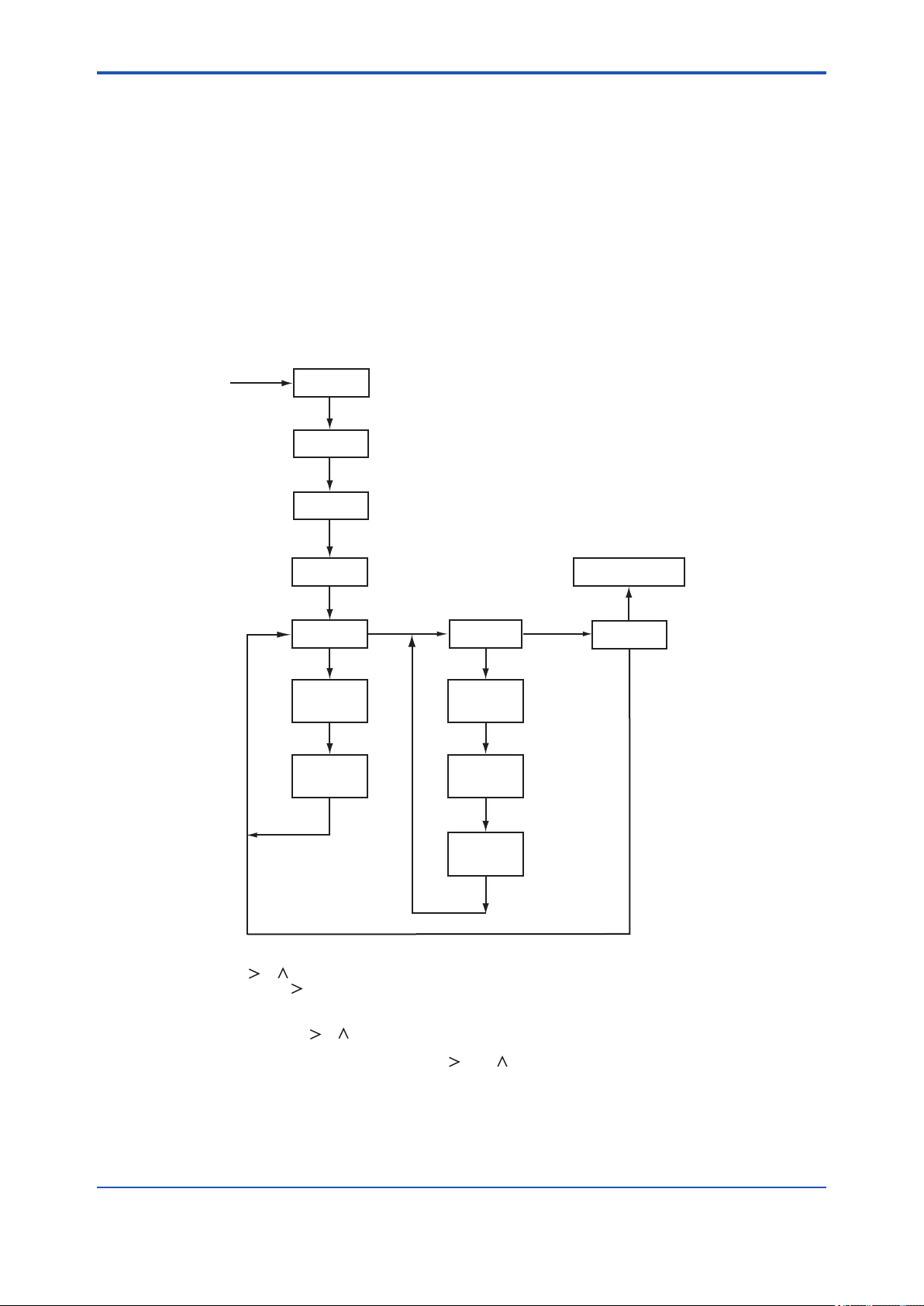
<6. CALORIE / PARAMETER SETTING>
(2) Density/Calorie Conversion Factor Setting Mode
In order to this mode, select “MAN.CAL” in before page, and press [YES] key.
This mode is used to set a factor for converting density to calorie. This setting is mandatory when
measuring the calorie.
(a) Automatic zero-point adjustment [AT_ADJ] : 0 to 133.000, 0 to 3.5000
(b) Factor setting [SET_K] :
• Zero point [K0_ADJ] : -99999 to 99999
• K0 [K0] : -99999 to 99999
• K1 [K1] : 0 to 99999
Note: The result of executing item (a) above is also reected on [K0_ADJ] in item (b).
6-9
1
*
MAN.CAL
[YES]
ZERO
[NO]
SPAN
[NO]
ADJUST
[YES]
AT_ADJ
XXX.XXX
VALVE
XXX.XXX
CAL.SET
[YES]
[ENT]
[ENT]
Measurement mode
[YES]
[YES]
[NO]
END
[NO]
[NO]
SET_K
X.XXXX
3
*
K0_ADJ
[ENT]
2
*
X.XXXX
[ENT]
2
*
4
*
K0
X.XXXX
[ENT]
2
*
F0602.ai
K1
*1: See "Figure 6.1 Modes of Operation Level" on page 6-8.
*2: Using the [ ], [ ] and [ENT] keys, set a value (numeral position of the decimal point and sign).
Each press of the [ ] key moves through the fields of the numeral decimal point and sign in this order.
If you enter a value that exceeds the limits, the display shows [*OVER].
Press the [YES] or [NO] key to re-set the value.
*3: Set a value using the [ ], [ ] and [ENT] keys.
*4 When the reading stabilizes, press the [ENT] key to confirm the factor.
This parameter does not accept input from the [ ] and [ ] keys.
Figure 6.2 Density / Calorie Conversion Factor Setting Mode
IM 11T3E1-01E
Page 99

<6. CALORIE / PARAMETER SETTING>
(3) Display Mode
Select one of the following seven parameters to be shown in the message eld. Each press of
the [NO] key cycles through the choices in the order shown below:
1. Physical density [XX.XXXX KG/M3] or [XX.XXXX LB/FT3]
(depends on the setting of CODE 21)
2. Compensated density [X.XXXX KG/M3 ]or [X.XXXXX LB/FT3]
(depends on the setting of CODE 21)
3. Caloric value [XXX.XXX MJ/M3] or [XX.XXXX KBTU]
(depends on the setting of CODE 22)
4. Temperature [XXX.X °C] or [XXX.X °F]
(depends on the setting of CODE 23)
5. Pressure [XXX.XX KPA] or [X.XXXX MPA] or [XX.XXX PSI]
(depends on the setting of CODE 20)
6. Current for analog output 1 (%) [XXX.X MA1%]
7. Current for analog output 2(%) [XXX.X MA 2%]
Show the desired choice and press the [YES] key. That choice is set as a parameter to be measured in the measurement mode (<MEASURE>). Parameters 1, 2 and 3 are congurable, while
parameters 4 to 7 are read-only.
6-10
IM 11T3E1-01E
Page 100
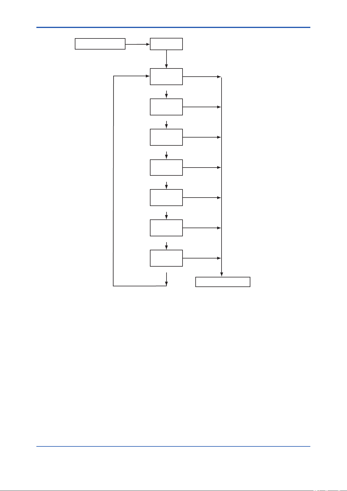
<6. CALORIE / PARAMETER SETTING>
6-11
1
Measurement Mode
*
[MODE]
DISP
[YES]
XX.XXXX
KG/M3
(Physical density)
[NO]
X.XXXX
KG/M3
(Compensated density)
[NO]
XXX.XXX
MJ/M3
(Calorific value)
[NO]
XXX.X
°C
(Sample gas temperature)
[NO]
XXX.XX
KPA
(Sample gas pressure)
[NO]
XXX.X
MA1%
(Current for analog output1(%))
[NO]
XXX.X
MA2%
(Current for analog output 2(%))
[NO]
2,
*
[YES]
[YES]
[YES]
[YES]
(Read-only)
[YES]
(Read-only)
*
2,
*
*
2,
*
*
2
*
2
*
[YES]
(Read-only)
[YES]
(Read-only)
Measurement Mode
3
3
3
*1: See "Figure 6.1 Modes of Operation Level" on page 6-8.
*2: The unit is the one set the service level.
*3: Press the [YES] key to show the parameter in the measurement mode.
Figure 6.3 Display Mode (DISP Mode)
F0603.ai
IM 11T3E1-01E
 Loading...