

Page 1

User's
Manual
GC1000 Mark II
Process Gas Chromatograph
Overview
IM 11B03A03-01E
IM 11B03A03-01E
3rd Edition
Page 2
<T oc> <Ind> <Rev> <Introduction>
◆ Notice
● Regarding This Manual
1. This Manual should be passed on to the end user.
2. Read this manual carefully and fully understand how to operate this product before
you start operation.
3. Y okogawa makes no warranty of any kind with regard to this material, but not limited
to, implied warranties of merchantability for particular purpose.
4. All rights reserved. No part of this manual may be reproduced in any form without
Y okogawa’ s written permission.
5. Great effort has been expended to ensure that the descriptions in this manual are
correct. Should you, however, come across a questionable area or note an inconsistency , a telephone call or letter to Yokogawa.co.,ltd. noting the questionable area
would be highly appreciated.
6. The contents of this manual are subject to change without prior notice.
i
● Regarding Protection, Safety , and Prohibition Against Unauthorized Modifica-
tion.
1. For the protection and safe use of the product and the system controlled by it, be sure
to follow the instructions on safety described in this manual when handling the product. In addition, if you handle the product in contradiction to these instructions, our
company does not guarantee safety .
2. The following safety symbol marks are used on the product concerned or in this
Manual :
WARNING
A WARNING sign denotes a hazard. It calls attention to procedure, practice, condition
or the like, which, if not correctly performed or adhered to, could result in injury or
death of personnel.
CAUTION
A CAUTION sign denotes a hazard. It calls attention to a procedure, practice, condition or the like, which, if not correctly performed or adhered to, could result in damage
to or destruction of part or all of the product.
IMPORT ANT :
Indicates that operating the hardware or software in this manner may damage it or
lead to system failure.
NOTE:
Draws attention to information essential for understanding the operation and features.
TIP:
Gives information that complements the present topic.
All Rights Reserved Copyright © 2001, Y okogawa Electric Corporation
IM 11B03A03-01EMedia No. IM 11B03A03-01E 3rd Edition : Aug. 2006 (YK)
3rd Edition : Aug. 23. 2006-00
Page 3

<T oc> <Ind> <Rev> <Introduction>
See Also:
Gives the reference locations for further information on the topic.
Protective ground terminal:
In order to provide protection against electrical shock in case of a fault. This symbol
indicates that the terminal must be connected to ground prior to operation of equipment.
Function ground terminal:
In order to provide protection against noise. This symbol indicates that the terminal
must be connected to ground prior to operation of equipment.
Alternating current
ii
3. If protection / safety circuits are to be used for the product or the system controlled by
4. When you replace parts or consumables of the product, use those specified by our
5. Do not modify the product.
Indicates the power switch state “ON”.
Indicates the power switch state “Stand - by”.
Indicate the power switch state “OFF”.
it, they should be installed outside of the product.
company .
● Exemption from Responsibility
1. Y okogawa Electric Corporation does not make any warranties regarding the product
except those mentioned in the WARRANTY that is provided separately.
2. Y okogawa Electric Corporation assumes no liability to any party for any loss or damage, direct or indirect, caused by the use or any unpredictable defect of the product.
● Regarding Software and set including Software Supplied by Y OKOGA WA
1. Y okogawa makes no other warranties expressed or implied except as provided in its
warranty clause for software supplied Y okogawa.
2. Use this software with one specified computer only.
Y ou must purchase another copy of the software for use with each additional com-
puter.
3. Copying this software for purposes other than backup is strictly prohibited.
4. Store the streamer or floppy disk (original medium) in a secure place.
5. Reverse engineering such as the disassembly of software is strictly prohibited.
6. No portion of the software supplied by Y okogawa may be transferred, exchanged, or
sublet or leased for use by any third party without prior permission by Y okogawa.
IM 11B03A03-01E 3rd Edition : Aug. 23. 2006-00
Page 4
<T oc> <Ind> <Rev> <Introduction>
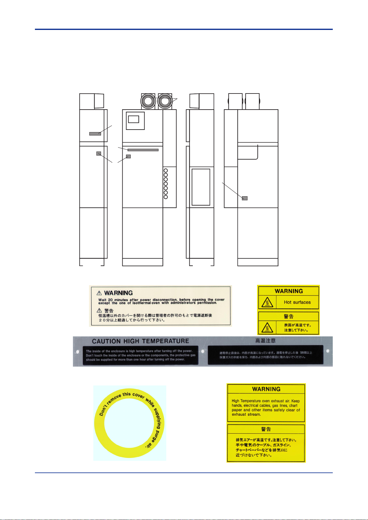
◆ Warning/Caution Labels
● T o ensure safety operation of this equipment, warning/caution labels are at-
tached on the equipment as follows. Check these labels for your safety operation.
D
A
C
B
E
iii
[Left side] [Front] [Right side] [Back]
F0001.EPS
AB
C
The inside of the enclosure is high temperature after turning off the power.
Don’t touch the inside of the enclosure or the compponents, the protective gas
should be suoolied for more than one hour after turning off the power.
D
E
F0002.EPS
IM 11B03A03-01E 3rd Edition : Aug. 23. 2006-00
Page 5

<T oc> <Ind> <Rev> <Introduction>
◆ Introduction
Thank you for purchasing the GC1000 Mark II process gas chromatograph.
This manual describes the technical information on overview of Model GC1000D /
GC1000S / GC1000T / GC1000E / GC1000W / GC1000C (Hereafter , it is abbreviated as
GC1000 Mark II) Process Gas Chromatograph.
Please lead the following respective documents before installing and using the GC1000
Mark II system.
● Documents Related to the GC1000 Mark II Process Gas Chromatograph
1. Instruction manuals
The product comes with the following instruction manuals.
■ Instruction manuals that do not depend upon the specifications of the product
(1) Overview (IM 1 1B03A03-01E)
(2) Basic Operation and Startup (IM 1 1B03A03-02E)
(3) Maintenance and Inspection Manual (IM 1 1B03A03-04E)
iv
(4) LCD Panel Operation Manual (IM 1 1B03A03-05E)
(5) Alarm Message Manual (IM 1 1B03A03-06E)
(6) Password Manual (IM 1 1B03A03-07E)
and Installation Manual (TI 1 1B03A03-13E)
■ Instruction manuals that depend upon the specifications of the product
(1) GCMT Gas Chromatograph Maintenance Terminal Software Package Operation
Guide (IM 1 1B03G03-03E)
(2) Capture It! Manual (IM 1 1B3G1-02E)
■ Instruction manuals for related products
(1) PCAS PC Analyzer Server Software (IM 11B06B01-01E)
(2) ASET Analyzer Server Engineering Terminal Software (IM 1 1B06C01-01E)
(3) GCET GC Engineering Terminal Software (IM 1 1B06D01-01E)
(4) ASGW Analyzer Server Gateway Software (IM 11B06E01-01E)
(5) ASIU Analyzer Server Interface Unit Software (IM 11B06F01-01E)
IM 11B03A03-01E 3rd Edition : Aug. 23. 2006-00
Page 6

<T oc> <Ind> <Rev> <Introduction>
2. Operation Data
Operation data is supplied with the operation manuals in the delivered package and contains the following required to use the gas chromatographs.
● Process conditions and measurement range
● Instrument specifications and operating conditions
● Standard sample for calibration
● Column system and column
● Miscellaneous data
Chromatogram, base line, repeatability , power supply voltage variation, etc.
● Analyzer flow diagram and installation
● Parts composition table
● General connection diagram
● Sampling system diagram (only if supplied by Yokogawa)
● Is the System Ready?
Before reading this manual, the following preparations must have been completed.
● The system must be unpacked and installed in the correct place.
v
● The piping for the utility gases such as carrier and calibration gases must be completed, followed by leak checking.
● The wiring for the power supply and others must be completed.
If these have not been completed yet, see the Installation Manual (TI 1 1B03A03-13E).
After completion, return to this manual and do the following:
● If the system power is on, turn off the power .
● Shut off all the gases at the flow control units.
Please read the following respective cautions (General Precautions, Caution of
using Explosion-Protection Instruments, on Piping Construction, and on Piping
Work) before installing and using the GC1000 system.
IM 11B03A03-01E 3rd Edition : Aug. 23. 2006-00
Page 7
<T oc> <Ind> <Rev> <Introduction>
● General Precautions
WARNING
(1) In order to analyze gases, process gas chromatographs use a sample of the process
gas and utility gases.
Since these gases are typically combustible, combustion-sustaining, toxic,
odorous, resolvable, polymerizing, or corrosive, refer to the “Safety Information” in our approval drawings and others to ensure safety thoroughly before
using these analyzers.
(2) Up to two protection systems, each of which weighs approximately 10 kg, are installed
on top of the GC1000. Therefore, the center of gravity is higher than the center of the
analyzer body .
Take great care when carrying and installing (piping- wiring) the GC1000. The
GC1000 must be carried and installed very carefully (including piping and
wiring) by more than one person (at least four people are recommended).
(3) Since the GC1000 are precision instruments, take care when handling not to jolt
of knock them.
(4) Use the GC1000 within the range of your purchase specifications.
vi
Y okogawa assumes no responsibility for problems resulting from use by the customer
outside the purchase specifications.
If the GC1000 need to be modified or repaired, please contact your nearest Y okogawa
representative. Yokogawa assumes no responsibility for results where the customer or
any third party has attempted to modify or repair these products.
(5) When touching LCD Panel switches
When touching LCD Panel switches, first, discharge Electro Static Charge of the body .
Then, touch the LCD Panel switches. If not, LCD display may be changed by Electro
Static Discharge.
IMPORT ANT :
(1) Read the attached instruction manual before operating the GC1000
(2) The instruments must be installed and operated according to the installation manual,
instruction manual, approval drawings, and operation data.
IM 11B03A03-01E 3rd Edition : Aug. 23. 2006-00
Page 8

<T oc> <Ind> <Rev> <Introduction>
● CA UTIONS OF USING EXPLOSION-PRO TECTION INSTR UMENTS
The GC1000 Process Gas Chromatographs are designed to protect against explosion.
When these analyzers are used in a hazardous area, observe the following precautions.
Since the applicable standard differs depending on the specifications of the analyzer to be
used, check the specifications of your analyzer.
(1) Kinds of explosion protection
To assure explosion protection, the GC1000 Process Gas Chromatographs have a pressurized and flameproof construction, or type X purging and explosionproof construction
meeting the following standards :
<GC1000D / GC1000S>
• JIS Expd IIB + H2 T1 (programmed-temperature oven 320˚C max., isothermal oven
225˚C max., liquid-sample valve 250˚C max.)
• JIS Expd IIB + H2 T2 (programmed-temperature oven 225˚C max., isothermal oven
225˚C max., liquid-sample valve 225˚C max.)
• JIS Expd IIB + H2 T3 (programmed-temperature oven 145˚C max., isothermal oven
145˚C max., liquid-sample valve 145˚C max.)
vii
• JIS Expd IIB + H2 T4 (programmed-temperature oven 95˚C max., isothermal oven
95˚C max., liquid-sample valve 95˚C max.)
<GC1000W / GC1000C>
CENELEC (A TEX directive) certified : Group II Category 2G
• EEx pd II B +H2 T1 (programmed-temperature oven 320°C max, isothermal oven
225°C max., liquid-sample valve 250°C max.)
• EEx pd II B +H2 T2 (programmed-temperature oven 225°C max, isothermal oven
225°C max., liquid-sample valve 225°C max.)
• EEx pd II B +H2 T3 (programmed-temperature oven 145°C max, isothermal oven
145°C max., liquid-sample valve 145°C max.)
• EEx pd II B +H2 T4 (programmed-temperature oven 95°C max, isothermal oven 95°C
max., liquid-sample valve 95°C max.)
<GC1000T / GC1000E>
FM Type X purging and Explosionproof for CLI, DIV1, GPS B, C & D, NEMA3R.
Type Y purging and Type X purging for CLI, DIV1, GPS.B, C & D, NEMA3R.
• T1 (programmed-temperature oven 320˚C max., isothermal oven 225˚C max., liquidsample valve 250˚C max.)
• T2 (programmed-temperature oven 225˚C max., isothermal oven 225˚C max., liquidsample valve 225˚C max.)
• T3 (programmed-temperature oven 145˚C max., isothermal oven 145˚C max., liquidsample valve 145˚C max.)
• T4 (programmed-temperature oven 95˚C max., isothermal oven 95˚C max., liquidsample valve 95˚C max.)
IM 11B03A03-01E 3rd Edition : Aug. 23. 2006-00
Page 9

<T oc> <Ind> <Rev> <Introduction>
CSA Type X purging and Explosionproof for CLI, DIV1, GPS B, C & D, NEMA3R.
Type Y purging and T ype X purging for CLI, DIV1, GPS.B, C & D, NEMA3R.
• T1 (programmed-temperature oven 320˚C max., isothermal oven 225˚C max., liquidsample valve 250˚C max.)
• T2 (programmed-temperature oven 225˚C max., isothermal oven 225˚C max., liquidsample valve 225˚C max.)
• T3 (programmed-temperature oven 145˚C max., isothermal oven 145˚C max., liquidsample valve 145˚C max.)
• T4 (programmed-temperature oven 95˚C max., isothermal oven 95˚C max., liquidsample valve 95˚C max.)
(2) Precautions for Explosionpr oof section (The analyzer with optional
code "FM/CSA T ype Y purging" does not have the e xplosionproof
section.)
When handling the screws on the cover of the Protection system, note the following to
avoid damaging the screws since they cannot be repaired.
(1) The enclosure is pressurized. Before removing the cover, reduce the internal pres-
sure by loosening the sealing plug for wiring on the enclosure or relevant means.
viii
(2) When removing the cover, prevent any dirt or foreign matter from contaminating the
screw part.
(3) When installing the cover, tighten the screws by hand ; never use tools.
(4) Since the screws are coated with MOL YKOTE, do not lubricate them.
(3) Precautions when using hydrogen gas
When using hydrogen gas as the carrier gas, the FID or FPD combustion gas, to ensure
safety , install the analyzer in a location equipped with a ventilator or where there is sufficient ventilation. Make sure there are no gas leaks from the pipe joints and inspect for
leaks.
(4) Installation site and environment
The analyzer specifications allow it to be used in hazardous areas as defined by Zone1 IIB
+ H
, T2, T3, T4 (JIS / CENELEC) or DIV1, GPS B, C & D, T1, T2, T3, T4 (FM / CSA).
2T1
However, never install the analyzer in an area where the density of explosive gas persists
for a long time.
(5) Wiring works
Model GC1000D / GC1000S, analyzer obtains explosion proof authorization by the complete set including metal fittings of the attachment.
When performing wiring, always use the attached sealing fittings and flameproof packing
adapter.
IM 11B03A03-01E 3rd Edition : Aug. 23. 2006-00
Page 10

<T oc> <Ind> <Rev> <Introduction>
(6) Maintenance and inspection
During usual maintenance and inspection, it is not necessary to check the explosionprotected section.
Before opening the door of the explosion-protected section for maintenance and inspection, be sure to turn off the power . After completing maintenance and checks, close the
door completely then turn on the power after checking that the specified explosion protection performance is guaranteed. The parts to be checked are described in the Maintenance
and Inspection Manual (IM 1 1B03A03 - 04E).
If any of the following damage occurs, contact a Yokogawa sales representative or the
Y okogawa sales division
(1) If the screws securing the Protection System (explosionproof construction) are dam-
aged
(2) If the exterior or light transmission section of the enclosures is damaged
(3) If packings are cracked or conspicuously deformed
(7) Override function (The analyzer with optional code "FM/CSA T ype Y
purg ing" does not have this function.)
ix
WARNING
• When the override function is used, Analyzer becomes an ignition source and the high
temperature and the high voltage part will be exposed.
• Please confirm that in the ambient atmosphere, the concentration of explosive gases
is less than the allowable limit, by using a gas detector.
To return to the normal operation, turn off “the override switch” and then close the door as it
was before turning on power.
In this analyzer, if the pressure of the pressurized / type X purged enclosure system (oven,
electronic section) drops while the power is on, the pressurized explosion protection section is activated to stop power supply . Therefore, in case of opening the door of the oven or
of the electronic section inadvertently , for maintenance, while the power is on, the protection system is activated to cut off the power .
The “override function” intensively releases this function of protection system.
The override switch is installed in section.
(8) Replacing parts
Always use parts specified by Yokogawa when replacing parts, for replacement, refer to the
Maintenance and Inspection Manual (IM 1 1B03A03 - 04E).
IM 11B03A03-01E 3rd Edition : Aug. 23. 2006-00
Page 11

<T oc> <Ind> <Rev> <Introduction>
(9) Operation
WARNING
<CENELEC>
* Only trained persons may use this instrument in a hazardousl location.
* Do not open when energized.
<FM>
For type X purging:
* This equipment contains components that operate at high temperature. The equip-
ment shall be deenergized for 60 minutes to permit those components to cool before
the enclosure is opened unless the area is demonstrated to be nonhazardous at the
time.
* Enclosure shall not be opened unless the area is known to be nonhazardous, or
unless all devices within have been de-energized.
x
* Power shall not be restored after enclosure has been opened until enclosure has
been purged for 12 minutes. (When the internal pressure is restored, the system
automatically purges over the 12 minutes, then turns on the power again.)
For explosionproof enclosure:
* Seal all conduits within 18 inches
* Open circuit before removing cover.
For type Y purging:
* Enclosure shall not be opened unless the area is known to be non-hazardous, or
unless all devices within have been de-energized. Power shall not be restored after
enclosure has been opened until enclosure has been purged for 12 minutes at specified pressure indicated by the pressure gauge labeled “EL.BOX” in the pressure and
flow control section.
* Alarm shall be provided and connected to alarm contact output.
(a) The alarm shall generate a visual or audible signal that attracts attention
(b) The alarm shall be located at constantly attended location.
(c) Electrical alarms shall be approved for the location in which they are installed.
IM 11B03A03-01E 3rd Edition : Aug. 23. 2006-00
Page 12

<T oc> <Ind> <Rev> <Introduction>
<CSA>
For type X purging:
* This equipment contains components that operate at high temperature. The equip-
ment shall be deenergized for 60 minutes to permit those components to cool before
the enclosure is opened unless the area is demonstrated to be nonhazardous at the
time.
* Enclosure shall not be opened unless the area is known to be non-hazardous, or
unless all devices within the enclosure have been de-energized. Power must not be
restored after enclosure has been opened until enclosure has been purged for 12
minutes at a flow rate of 0.05m
* Power will automatically be removed when purge pressure falls below 40 mm (1.6 in)
of water column.
For explosionproof enclosure:
* A seal shall be installed within 50 cm of the enclosure.
* Open circuit before removing cover.
For type Y purging:
* Enclosure shall not be opened unless the area is known to be non-hazardous, or
unless all devices within the enclosure have been de-energized. Power must not be
restored after enclosure has been opened until enclosure has been purged for 12
minutes at a flow rate of 0.05m
3
/min.
3
/minute min.
xi
* Remove power below 40mm (1.6in) of water column.
Take care not to generate mechanical spark when accessing to the instrument and peripheral devices in hazardous locations.
Do not press prick the keyboard of LCD panel (operation and display section) using such
as knives and sticks.
(10) Maintenance and Repair
The instrument modification or parts replacement by other than authorized representative
of Yokogawa Electric Corporation is prohibited and will void the approval of Factory Mutual
Research Corporation and CSA certification and CENELEC certification .
IM 11B03A03-01E
3rd Edition : Aug. 23. 2006-00
Page 13
<T oc> <Ind> <Rev> <Introduction>
● Precautions Against Electrostatic Pr oblems
The GC1000 system uses numerous IC components. When handling cards with IC
components mounted on them for maintenance or setting changes, take full precautions against electrostatic problems.
These precautions are summarized below.
(a) When storing or carrying cards, enclose them in a conductive bag or antistatic
bag. (Cards as shipped by Yokogawa are enclosed in a conductive bag or
antistatic bag labeled with cautions against electrostatic problems.)
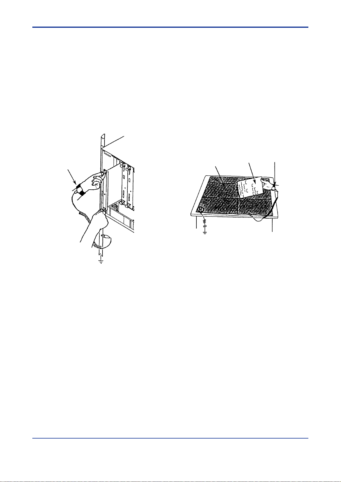
(b) Whenever mounting or demounting cards into or from a product, wear a wrist
strap grounded via a 1 MΩ resistance. Connect the wrist strap to any ground
terminal near the ground wire or to any unpainted part of the grounded frame.
xii
List strap
Sheet
1M‰
Using a wrist strap and conductive sheet Using a Conductive Sheet
Gard
List strap
F0003.EPS
(c) When servicing cards on the bench, place them on a conductive sheet
grounded via a 1 MΩ resistance, wearing a wrist strap as in (2) above. Keep
easily-chargeable plastic materials away from the bench.
(d) Never touch components mounted on the cards, the pattern side, connectors,
pin components, etc. with bare hands, unless using a wrist strap and a conductive sheet.
(e) Wrist straps and conductive sheets are available from Yokogawa Engineering
Service (YSV).
IM 11B03A03-01E
3rd Edition : Aug. 23. 2006-00
Page 14

<Int> <Ind> <Rev>
GC1000 Mark II Process Gas Chromatograph
Overview
CONTENTS
◆ Notice .......................................................................................................... i
◆ W arning/Caution Labels............................................................................iii
◆ Introduction ...............................................................................................iv
1. Principle of Gas Chr omatograph ........................................................... 1-1
1.1 Sampling Mechanism ..................................................................................... 1-1
1.2 Component Separation Using Column.......................................................... 1-2
1.3 Detector ........................................................................................................... 1-3
2. Terminology ............................................................................................ 2-1
Toc-1
IM 11B03A03-01E 3rd Edition
2.1 Operation Terminology ................................................................................... 2-1
2.2 Instrument Terminology.................................................................................. 2-2
3. System Configuration ............................................................................ 3-1
3.1 T ype and Appearance..................................................................................... 3-1
3.2 Components and Their Functions.................................................................. 3-2
3.2.1. Protection System ............................................................................ 3-2
3.2.2 Electronic Section............................................................................. 3-2
3.2.3 Pressure and Flow Control Section................................................... 3-2
3.2.4 Isothermal Oven ............................................................................... 3-2
3.2.5 Programmed-temperature Oven ....................................................... 3-3
3.2.6 Analyzer Base Sampling Section ...................................................... 3-3
3.3 Block Diagram................................................................................................. 3-4
3.4 Internal Piping System Diagram .................................................................... 3-7
3.5 External Input and Output Signals............................................................... 3-12
4. Outline of Software................................................................................. 4-1
4.1 Status and Operation Mode............................................................................ 4-1
4.1.1 Process ............................................................................................ 4-2
4.1.2 Manual ............................................................................................. 4-5
4.1.3 Lab ................................................................................................... 4-5
4.2 Stream ............................................................................................................. 4-6
4.3 Method............................................................................................................. 4-7
4.4 Description of Actions.................................................................................... 4-9
4.4.1 Actions of Stream Sequence........................................................... 4-10
4.4.2 Actions of Stream (Continuous) .......................................................4-11
4.4.3 Actions of Stream (1 cycle) ............................................................. 4-13
IM 11B03A03-01E 3rd Edition : Aug. 23. 2006-00
Page 15

<Int> <Ind> <Rev>
5. Actions of External Input and Output Signals ....................................... 5-1
Toc-2
4.4.4 Actions of Calibration...................................................................... 4-14
4.4.5 Actions of V alidation........................................................................ 4-17
4.5 Computation and Processing ...................................................................... 4-20
4.5.1 Peak Processing............................................................................. 4-20
4.5.2 Deviation processing ...................................................................... 4-20
4.5.3 Additional processing...................................................................... 4-20
4.5.4 Signal Processing........................................................................... 4-21
4.6 Alarm Processing ......................................................................................... 4-22
5.1 Analog Hold Output ........................................................................................ 5-1
5.1.1 When Actual Stream is Specified for Stream Number (without Stream
Identification Signal) ......................................................................... 5-2
5.1.2 When Actual Stream is Specified for Stream Number (with Stream
Identification Signal) ......................................................................... 5-3
5.1.3 When "99" is Specified for Stream Number (with Stream Identification
Signal) .............................................................................................. 5-4
5.2 Contact Output................................................................................................ 5-5
5.2.1 Stream Sequence............................................................................. 5-5
5.2.2 Stream.............................................................................................. 5-6
5.2.3 Operation Mode................................................................................ 5-6
5.2.4 Alarm................................................................................................ 5-6
5.2.5 Timing............................................................................................... 5-6
5.3 Contact Input................................................................................................... 5-7
5.4 Communication Input and Output ................................................................. 5-8
5.4.1 GC6 T ype Output Data Format (Fixed to 45 Characters)................... 5-8
5.4.2 GC6 T ype Input Data Format ............................................................ 5-9
5.4.3 GC8/GC1000 Type Output Data Format (Fixed to 45 Characters)....5-1 1
5.4.4 GC8/GC1000 T ype Input Data Format............................................ 5-12
5.4.5 MODBUS Communication Data Specification................................. 5-14
◆ Revision Record ......................................................................................... i
IM 11B03A03-01E
3rd Edition : Aug. 23. 2006-00
Page 16
<Toc> <Ind> <1. Principle of Gas Chromatograph >
1. Principle of Gas Chromatograph
A gas chromatograph is an analyzer which first sends a fixed volume of the sampled multicomponent gas mixture to a column, separates it in the column, then measures the concentrations of the components with a detector. The process gas chromatograph analyzes
intermittently , allowing periodic analysis in a specified sequence, thus automatic sampling
is possible.
This chapter explains the measurement principle of the GC1000 Process Gas Chromatographs.
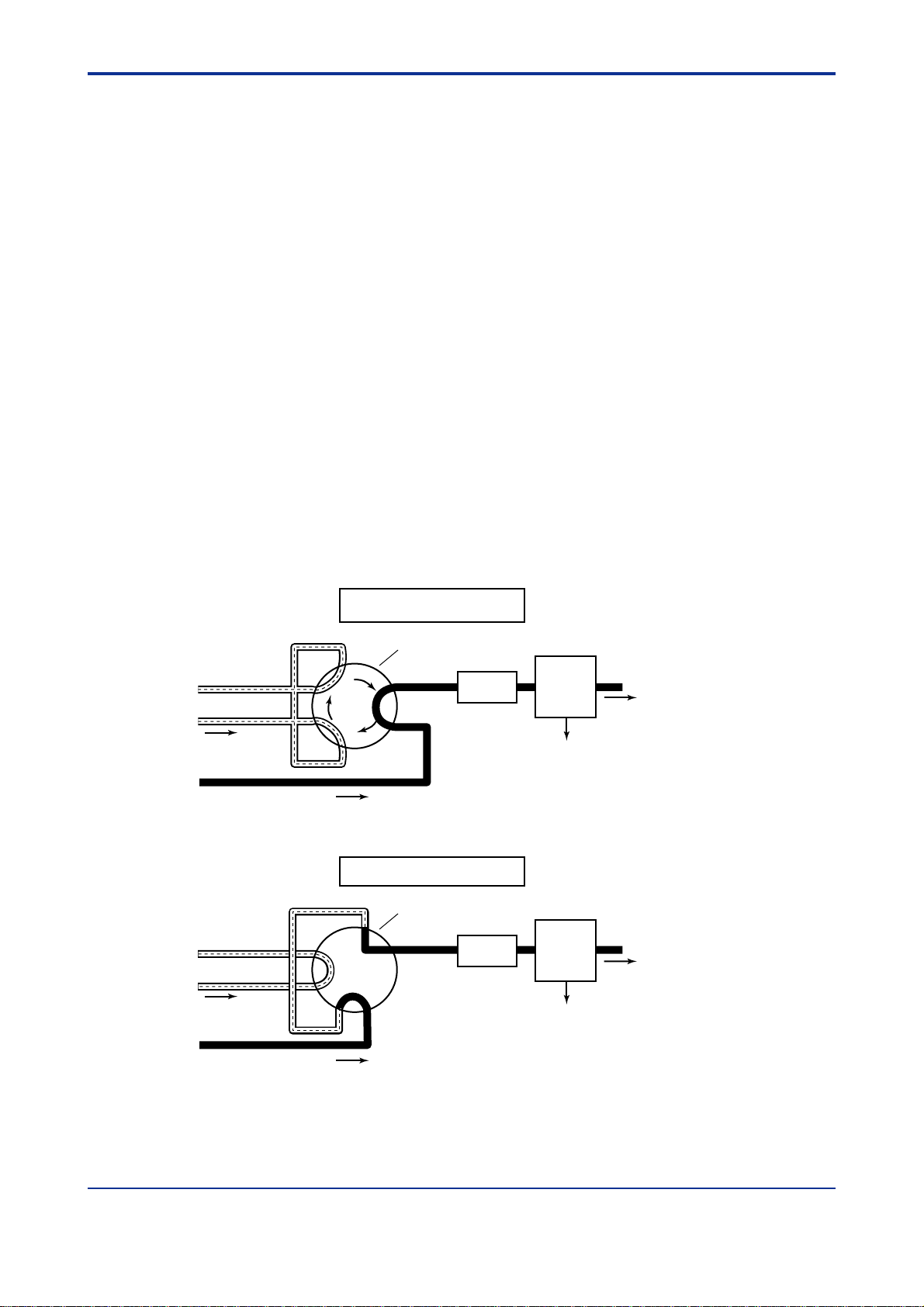
1.1 Sampling Mechanism
The process gas chromatograph consists of a sampling mechanism, a column and a
detector.
Sampling is carried out by switching a sampling valve. When separating components or
detecting concentrations, the sampling valve is set to allow the gas (liquid) to be measured
to flow through the sample column. When sampling, the sampling valve leads the gas
(liquid) to be measured to a column on a carrier gas. (See Figure1.1)
There are two important points regarding sampling: a regular volume is sampled since
repeated sampling is required; and samples are taken quickly and securely . The volume is
fixed by measuring a specific gas (liquid) of controlled temperature and pressure using a
sample measurement tube. Samples are taken quickly and securely by ensuring that the
gas to be measured always flows without interrupt.
1-1
Sample
Carrier gas
Sample
Carrier gas
Component separation and
concentration detection
Measuring tube
Sample valve
Vent
Column Detector
Electric signal
Status of sampling
Measuring tube
Sample valve
Vent
Column Detector
Electric signal
Figure 1.1 Basic Configuration of Gas Chromatograph
F0101.EPS
IM 11B03A03-01E 3rd Edition : Aug. 23. 2006-00
Page 17
<T oc> <Ind> <1. Principle of Gas Chromatograph >
1.2 Component Separation Using Column
Three types of columns are available for the GC1000 Process Gas Chromatographs: the
packed column, the mega-bore column and the capillary column.
The packed column consists of a stainless pipe, 2 mm in diameter and 0.2 to 2.0 m in
length and filled with a bulking agent called a stationary phase.
The mega-bore and capillary columns, of approximate diameter 0.5 mm and 0.3 mm
respectively , are coated inside a certain phase called a stationary phase.
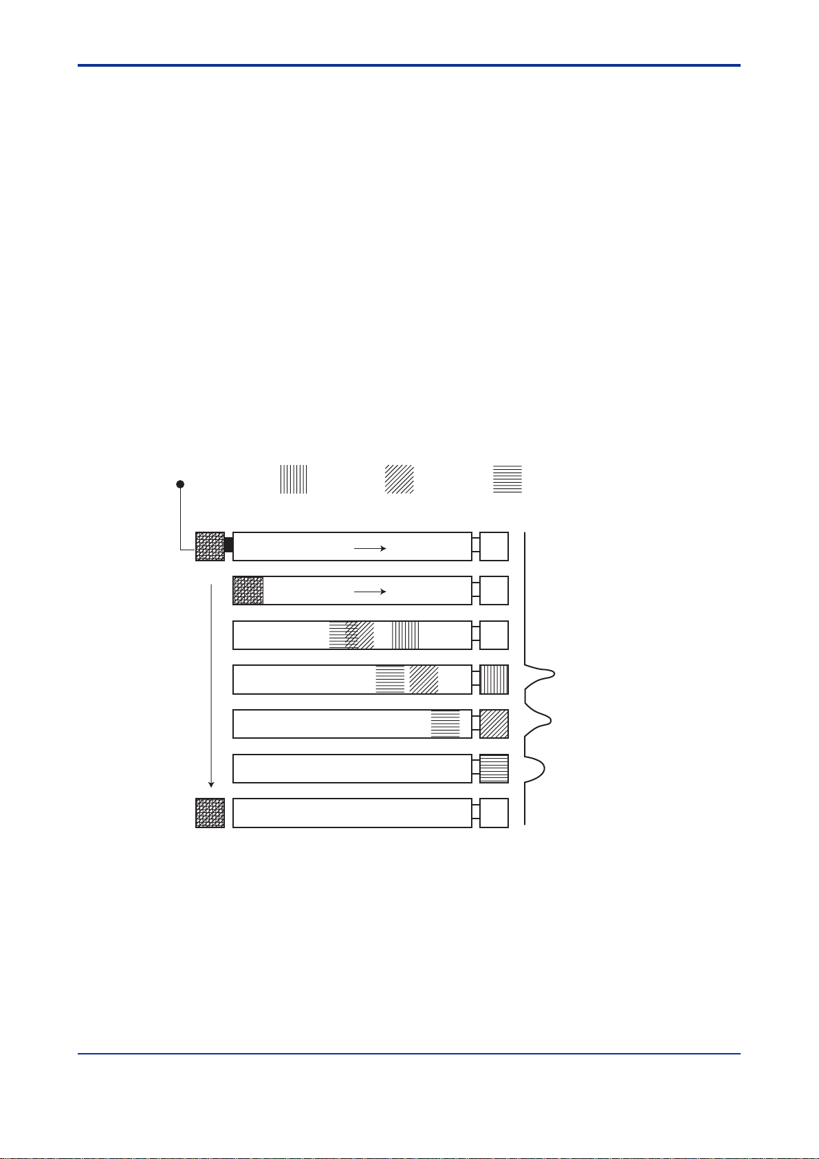
The components in the multi-component gas mixture sample with carrier gas, which called
mobil phase move through the column, repeatedly absorbing the stationary phase and
dissolving from the stationary phase at a certain cyclic rate conforming to a fixed partition
coefficient * that is unique to each component.
Since the transfer rates differ depending on the partition coefficient, a multi-component gas
mixture gradually separates into discrete components and is separated in the order of the
transfer rates.
* Partition coefficient : The concentration ratio of the components, calculated by dividing the component concentration which
is in equilibrium in the stationary phase by the concentration which is in equilibrium in the mobile
phase.
Figure 1.2 shows a diagram of how the multi-component gas mixture is led to a column and
separated into its discrete components over time.
1-2
Multi-component
gas mixture
Sampling
(1st round)
Time
(2nd round)
Figure 1.2 Separating Components Using a Column
(Intake) (Outlet)Column
Injection
:Component A, :Component B, :Component C
Detector Concentration signal
Carrier gas
Carrier gas
A
B
C
F0102.EPS
IM 11B03A03-01E 3rd Edition : Aug. 23. 2006-00
Page 18
<Toc> <Ind> <1. Principle of Gas Chromatograph >
1.3 Detector
The components separated in the column are led to the detector where the concentration
of each component is measured.
The GC1000 Process Gas Chromatographs can be fitted with thermal conductivity detectors (TCD), flame ionization detectors (FID) or flame photometric detectors (FPD). The
thermal conductivity detector can measure almost all non-corrosive components but
sensitivity is relatively low. On the other hand, the hydrogen flame ionization detector can
measure hydrocarbon and the flame photometric detector can measure sulfur compounds,
respectively with high sensitivity .
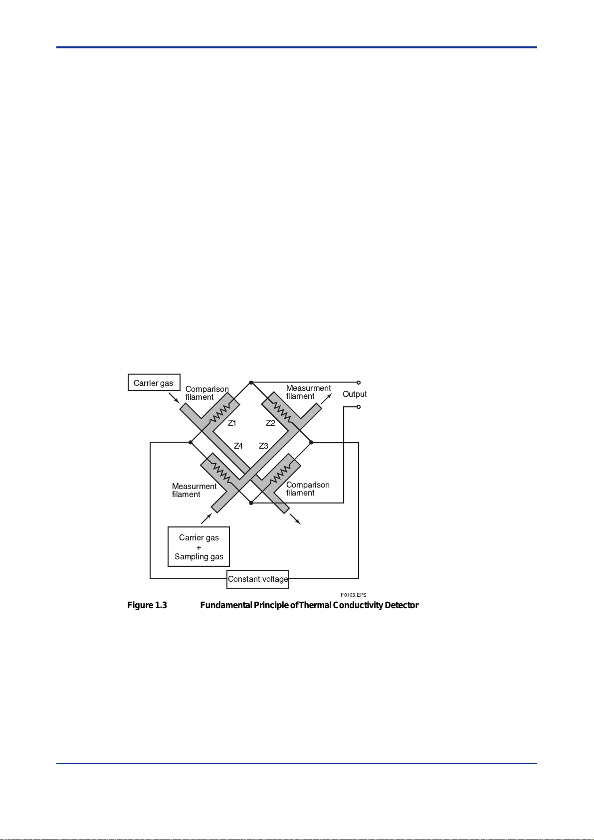
(1)Thermal Conductivity Detector (TCD)
The TCD utilizes the difference in the thermal conductivity between the measured gas and
the carrier gas and detects the unbalanced voltage produced in a bridge circuit as a measure of concentration.
Figure 1.3 shows the fundamental principle of the TCD. As shown, there are two streams,
each having two filaments. One stream passes the carrier gas only and the other, connected to the column outlet, allows the measured gas to pass during analysis. The filaments in the two streams form a bridge circuit such that the filament in one stream is
adjacent to the filament in the other stream. The unbalanced voltage in the bridge is proportional to the concentration of the measured gas (liquid) component.
1-3
The TCD is frequently used to measure the component concentration of the measured gas
(liquid).
Carrier gas
Figure 1.3 Fundamental Principle of Thermal Conductivity Detector
Comparison
filament
Measurment
filament
Carrier gas
+
Sampling gas
Z1 Z2
Z4 Z3
Constant voltage
Measurment
filament
Comparison
filament
Output
F0103.EPS
IM 11B03A03-01E 3rd Edition : Aug. 23. 2006-00
Page 19
<T oc> <Ind> <1. Principle of Gas Chromatograph >
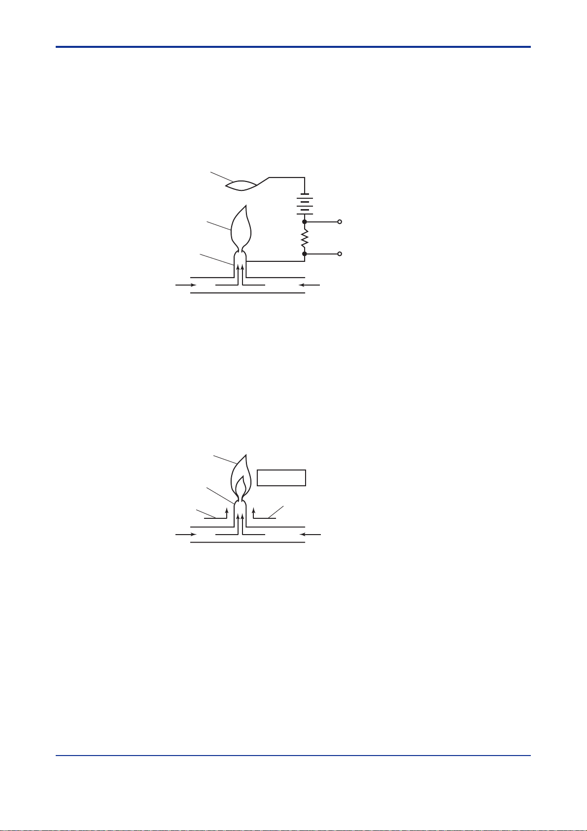
(2)Flame Ionization Detector (FID)
The FID utilizes the phenomenon that carbon molecules in the measured component
(hydrocarbon) are ionized in a hot hydrogen flame. That is, it detects the ionization current
which flows between electrodes to which a high voltage is applied. The ionization current is
proportional to the concentration of the measured component.
The FID is used to measure the component concentration of gases containing low concentrations of hydrocarbons.
Ion collector coil
+
-
-
+
+
Hydrogen flame
Jet pipe (nozzle)
+
-
+
-
Output
1-4
Carrier gas
+
Sampling gas
Figure 1.4 Fundamental Principle of Flame Ionization Detector
(3)Flame Photometric Detector (FPD)
Figure 1.5 shows the structure of the FPD. As the sample gas containing a sulfur component is led into the excess hydrogen flame, the component containing the sulfur atoms is
excited. The FPD detects the luminous intensity of the light emitted when this excited
component return to its base state using multiplier phototube and converts it to a voltage.
This voltage represents the concentration of the sulfur component in the measured gas.
The FPD can measure on the sulfur component with a high sensitivity of 1 ppm.
Hydrogen flame
Jet pipe (nozzle)
Hydrogen gas
for combustion
Carrier gas
+
Sampling gas
Figure 1.5 Basic Configuration of Flame Photometric Detector
Photomultiplier tube
Hydrogen gas for combustion
F0104.EPS
Hydrogen gas for combustion
Air fo combustion
F0105.EPS
IM 11B03A03-01E 3rd Edition : Aug. 23. 2006-00
Page 20

<Toc> <Ind> <2. T erminology >
2. Terminology
2.1 Operation Terminology
Term Description Notes
Remote Mode
Local Mode
Status
Process
Manual
Lab
Operation Mode
Run
Pause
Stop
Measurement Status
Stream Sequence
Stream (continuous)
Stream (1 cycle)
Calibration
Validation
Method
Analysis Cycle
Warming Up Time
Peak Detection Stop Time
Pause Time
Purging
Status accessible without password,
LCD/key: used only for reference
GCMT: connectable
Status accessible by entering password
LCD/key: used for changing settings
Normal measurement and calibration
Manual operation
Measurement with automatic peak detection, like a lab GC
Mode in which measurement is running
Mode in which measurement pauses
Mode in which measurement stops
Continuously measures streams in order specified in Stream Sequence
Continuously measures the specified stream
Measures the specified stream once
Performs calibration of the specified number
Performs validation of the specified number
Configures action timing of various valves and other parameters
Time from start (0 second) to stop of analysis
Time for displacement in sample streams
Time to stop peak detection of chromatogram compulsorily
Time for measurement pause
Displacement of the gas in the pressurized/Type X purged enclosures
with a protection gas
2-1
T0201.EPS
IM 11B03A03-01E 3rd Edition : Aug. 23. 2006-00
Page 21

<T oc> <Ind> <2. T erminology >
2.2 Instrument Terminology
Term Explanation Notes
TCD
FID
FPD
LSV
Restrictor
Methane converter
Sampling valve
Back-flush valve
Column switching valve
Atmospheric-pressure balancing
valve
Protection gas
Flame arrester
Splitter
Pressurized enclosure
Temperature protection circuit
Protection device
EPC
A thermal conductivity detector
A flame ionization detector
A flame photometric detector
A liquid sampling valve
A variable resistor
A methane reaction system : Methanizer
A valve for inputting samples
A switching valve for back flush
A valve for switching between columns
A balancing valve for sampling gases
Air
A device for protecting against "flame runaway"
A flow splitter
An enclosure whose internal pressure is kept high with protection gas
A circuit for turning off the heater to prevent overheating
A device for detecting a pressure drop in the analyzer to shut down the
power supply
Electric pressure controller
2-2
T0202.EPS
IM 11B03A03-01E 3rd Edition : Aug. 23. 2006-00
Page 22
<Toc> <Ind> <3. Overview >
3. System Configuration
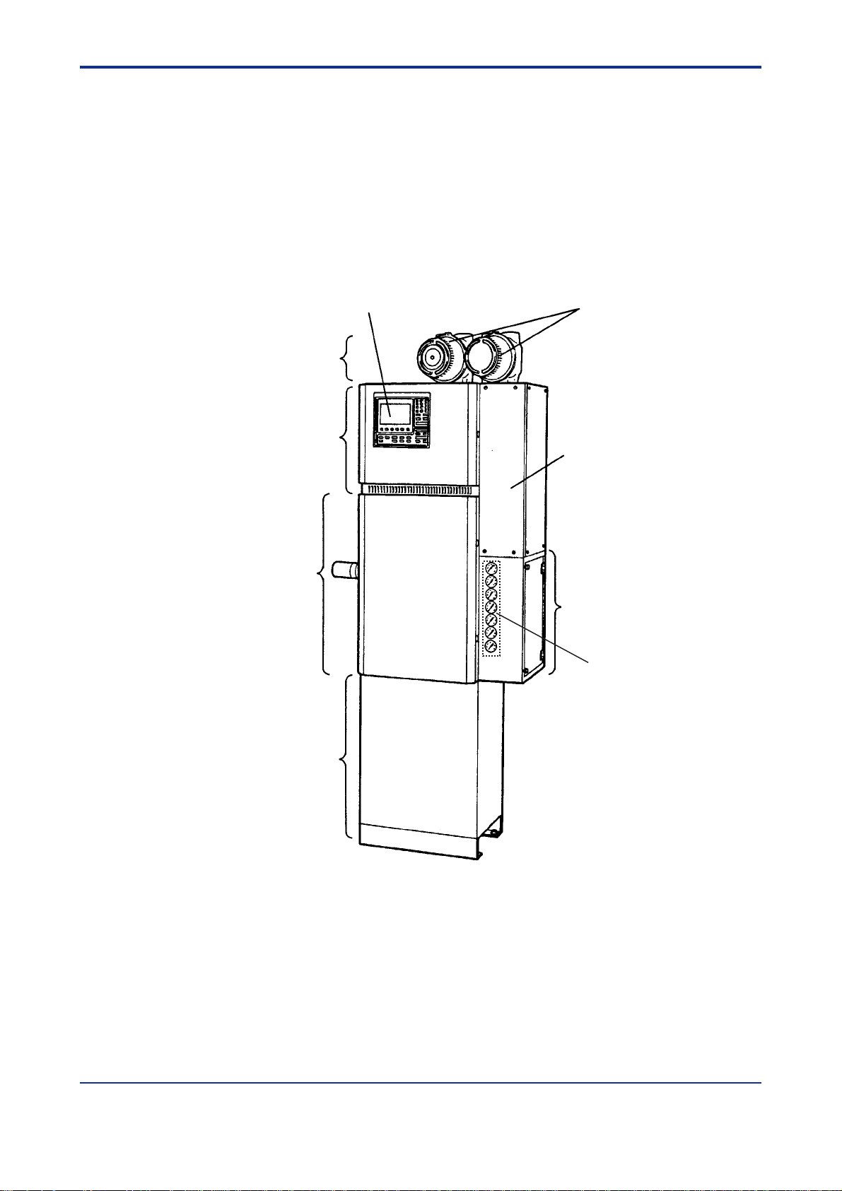
3.1 T ype and Appearance
The GC1000 Process Gas Chromatographs consist of (A) a protection system, (B) an
electronic section, (C) a pressure and flow control section, (D) an isothermal oven, (E) a
programmed-temperature oven (GC1000D / GC1000T / GC1000W) and (F) an analyzer
base sampling section (see Figure 3.1).
Note: There are two types of analyzer base sampling section, either the built-in type within GC1000 (the sample processor is
embedded), or the external type (the sample processor is separate). Select the type best suited to the intended usage.
Display Explosion proof enclosures
(number depends on
specifications)
(A) Protection system
(B) Electronic section
Terminal section
3-1
(D) Isothermal oven
(E) Programmed-temperature
oven
(F) Analyzer base
sampling section
(Note)
Figure 3.1Analyzer Components
(C) Pressure and
flow control section
EPC box
(in the case that EPC is installed)
F0301.EPS
IM 11B03A03-01E 3rd Edition : Aug. 23. 2006-00
Page 23

<T oc> <Ind> <3. Overview >
3.2 Components and Their Functions
3.2.1. Protection System
The protection system has a explosion-proof construction and is equipped with a built-in
protection circuit. The power relay , pressure switch, timer , relays, override switch, etc. are
internal to the instrument. The override function is particularly important for maintenance,
since it allows the power to be turned on even if there is an internal pressure loss. The
system monitors the internal pressures of the electronic section, isothermal oven and the
programmed-temperature oven (GC1000D / GC1000T / GC1000W), and if any of them
indicates an internal pressure lower than 392 Pa, it shuts down the power supply to those
components. After a power shut-down, when the internal pressure is restored, the system
automatically purges over the 12 minutes, then turns on the power again. Analyzers of nonexplosion-proof type and with FM/CSA T ype Y purging do not have this protection system.
3.2.2 Electronic Section
The electronic section has a pressurized protection/Type X purged structure and is designed for control of a detector, an isothermal oven, various valves and others, for processing and computation, and for output of the results. The LCD and operation keys on the
front of the electronic section allow manual operation of the GC1000 Mark II.
3-2
3.2.3 Pressure and Flow Control Section
The pressure and flow control sections control and indicate the pressures of sample gases,
standard gases, carrier gases, FID or FPD hydrogen (or nitrogen) for combustion, or FID or
FPD air for combustion. Regulator values or EPC is installed. It also contains pressurereducing valves for controlling purge gases, the air for actuating valves or the vortex tube,
an air-actuated valve for balancing atmospheric pressure, a vortex tube and a hydrogen
restriction system.
3.2.4 Isothermal Oven
The isothermal oven has an pressurized protection / T ype X purged structure. The temperature is set at a fixed level from 55 to 225°C (setting by 1°C unit). The isothermal oven
contains valves such as the sample valve which is air-activated, the back flush valve, the
column for separating a multi-component gas mixture into its individual components and
leading the components to the detector in sequence, the detector for detecting the components, and the restrictor for controlling the gas flow rate, etc.
There are three types of detector, the thermal conductivity detector (TCD), the flame
ionization detector (FID) and the flame photometric detector (FPD); either one or two of
these detectors can be used simultaneously (however, the FPD can only be installed in the
combustion chamber).
The component signals picked up by the detector are led to the electronic section for signal
processing.
IM 11B03A03-01E 3rd Edition : Aug. 23. 2006-00
Page 24

<Toc> <Ind> <3. Overview >
3.2.5 Programmed-temperature Oven
The programmed-temperature oven has an internal pressure protection / T ype X purged
structure. It contains a column that separates multi-component mixture samples into
individual components and leads them to the detector in sequence. The temperature can
be set to a fixed setting or it can be programmed. The allowable temperature range is 60 to
320°C without a cooling system, or 5 to 320°C with a cooling system, and the temperature
can be set to rise from between 0.1 to 30°C/min (setting by 0.1°C unit). Up to three temperature-rise patterns can be programmed.
3.2.6 Analyzer Base Sampling Section
The analyzer base sampling section is equipped with sample and standard gas streams,
and controls the sample pressure and flow rate. It also selectively sends the sample to be
analyzed in a stream, and can switch the standard gas to the isothermal or the programmed-temperature oven by a valve depending on the signal sent from the electronic
section.
If the analyzer does not contain the analyzer base sampling section, then samples can be
processed externally by supplying air to a separate sampling section.
3-3
IM 11B03A03-01E 3rd Edition : Aug. 23. 2006-00
Page 25

<T oc> <Ind> <3. Overview >
3.3 Block Diagram
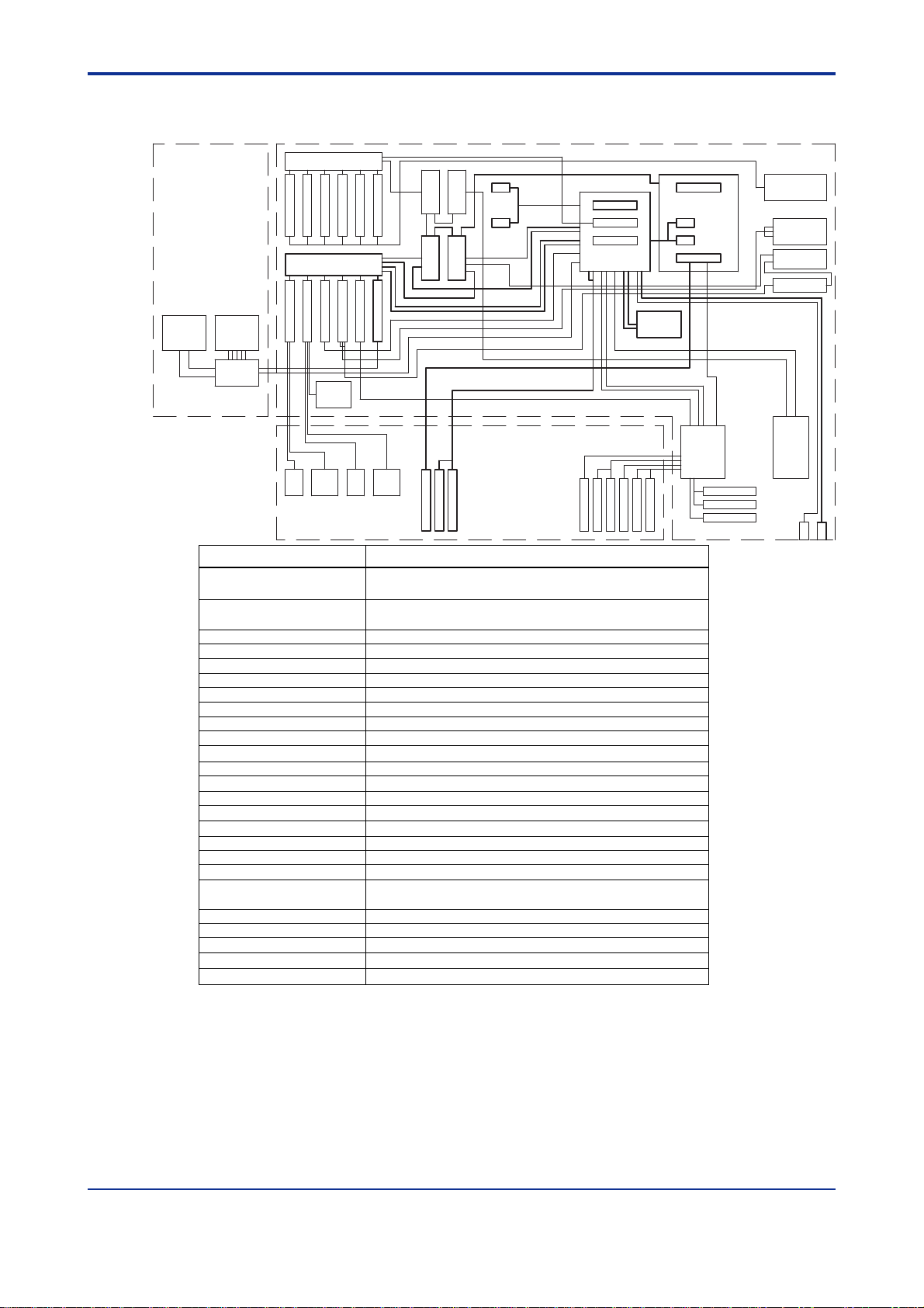
(1) GC1000D/GC1000T/GC1000W T ype X Purging
3-4
SHEETKEY LCD
LCD.KEY
BOARD
AO MOTHER BOARD
AO BOARD
AO BOARD
AO BOARD
BACKBOARD
AI CARD
DET2 CARD
DET1 CARD
P .SW P.SWP .SW
P.M B O ARD
AC/DC 24VAC/DC 24V
AO BOARD
AO BOARD
AO BOARD
AC/DC 15VAC/DC 3.3V
COM BOARD
COM BOARD
COM BOARD
MARSHALING.X
BOARD
Terminal
RELAY BOARD
Relay Relay
Terminal
POWER UNIT
SSRSSR
Terminal
Ether (*A) or (*B) is selected.
AO TERMINAL
BOARD
HUB TP
BOARD
(*A)
OPT CONVERTER
(*B)
TERMINAL
CPU CARD
TEMP CARD
ETHERNET CARD
DET1DET2
I.Oven Heter
C.Oven Heter
FID2 Heter
I.Oven PT100
I.Oven PT100
C.Oven PT100
C.Oven PT100
FID1 Heter
FID2 PT100
FID2 PT100
LSV2 Heter
FID1 PT100
FID1 PT100
LSV2 PT100
EV IF
BOARD
TEMP IF
BOARD
LSV1 Heter
LSV1 PT100
LSV2 PT100
LSV1 PT100
EPC
BOARD
P .SW
P .SW
F0302.EPS
(2) GC1000T Type Y Purging
AO MOTHER BOARD
AO BOARD
AO BOARD
AO BOARD
AO BOARD
BACKBOARD
AI CARD
DET1 CARD
LCDSHEETKEY
LCD.KEY
BOARD
DET2 CARD
ETHERNET CARD
DET2 DET1
Ether (*A) or (*B) is selected.
P.SW
AC/DC 3.3V AC/DC 15V
I.Oven PT100
C.Oven Heter
C.Oven PT100
P.SW
P.SW
C.Oven PT100
FID2 Heter
FID2 PT100
FID2 PT100
FID1 Heter
AO BOARD
AO BOARD
AC/DC 24V AC/DC 24V
CPU CARD
TEMP CARD
I.Oven Heter
I.Oven PT100
FID1 PT100
FID1 PT100
COM BOARD
COM BOARD
COM BOARD
MARSHALING.Y
BOARD
LSV2 Heter
LSV1 Heter
LSV2 PT100
LSV2 PT100
EV IF
BOARD
LSV1 PT100
LSV1 PT100
Terminal
POWER UNIT
SSR SSR
SSR SSR
Terminal
TEMP IF
BOARD
AO TERMINAL
BOARD
HUB TP
BOARD
OPT CONVERTER
TERMINAL
EPC
BOARD
(*A)
(*B)
P.SW
P.SW
IM 11B03A03-01E 3rd Edition : Aug. 23. 2006-00
Page 26

<Toc> <Ind> <3. Overview >
(3) GC1000S/GC1000E/GC1000C Type X Pur ging, with One Protection
System
3-5
SHEETKEY LCD
LCD.KEY
BOARD
AO MOTHER BOARD
AO BOARD
AO BOARD
AO BOARD
AO BOARD
BACKBOARD
DET2 CARD
DET1 CARD
ETHERNET CARD
FPD AMP
BOARD
MC MC
P .SW P.SW
P.M B O ARD
AC/DC 24VAC/DC 24V
AO BOARD
AO BOARD
AC/DC 15VAC/DC 3.3V
COM BOARD
COM BOARD
COM BOARD
MARSHALING.X
BOARD
Terminal
RELAY BOARD
Relay Relay
Terminal
POWER UNIT
SSR
Terminal
Ether (*A) or (*B) is selected.
AO TERMINAL
BOARD
HUB TP
BOARD
(*A)
OPT CONVERTER
(*B)
TERMINAL
CPU CARD
TEMP CARD
DET1DET2
I.Oven Heter
I.Oven PT100
I.Oven PT100
LSV2 Heter
LSV2 PT100
EV IF
BOARD
TEMP IF
BOARD
FPD PT100
FPD PT100
LSV1 Heter
LSV1 PT100
LSV2 PT100
LSV1 PT100
FPD Heter
EPC
BOARD
P .SW
P .SW
(4) GC1000S/GC1000E/GC1000C Type X Pur ging, with T wo Pr otection
Systems
SHEETKEY LCD
LCD.KEY
BOARD
AO MOTHER BOARD
AO BOARD
AO BOARD
AO BOARD
AO BOARD
BACKBOARD
AI CARD
DET2 CARD
DET1 CARD
ETHERNET CARD
FPD AMP
BOARD
MC MC
P.SW P.SW
P.M BOARD
AC/DC 24VAC/DC 24V
AO BOARD
AO BOARD
CPU CARD
TEMP CARD
DET1DET2
AC/DC 15VAC/DC 3.3V
I.Oven Heter
I.Oven PT100
I.Oven PT100
COM BOARD
COM BOARD
COM BOARD
MARSHALING.X
BOARD
LSV1 Heter
LSV2 Heter
LSV2 PT100
LSV2 PT100
LSV1 PT100
EV IF
BOARD
LSV1 PT100
Terminal
RELAY BOARD
Relay Relay
Terminal
POWER UNIT
SSR
Terminal
TEMP IF
BOARD
FPD PT100
FPD PT100
FPD Heter
Ether (*A) or (*B) is selected.
AO TERMINAL
BOARD
HUB TP
BOARD
OPT CONVERTER
TERMINAL
EPC
BOARD
(*A)
(*B)
P.SW
P.SW
IM 11B03A03-01E 3rd Edition : Aug. 23. 2006-00
Page 27
<T oc> <Ind> <3. Overview >
(5) GC1000E T ype Y Purging
AO MOTHER BOARD
AO BOARD
AO BOARD
AO BOARD
BACKBOARD
P.SW
AO BOARD
AO BOARD
AO BOARD
AC/DC 24V AC/DC 24V
P.SW
AC/DC 3.3V AC/DC 15V
COM BOARD
COM BOARD
COM BOARD
MARSHALING.Y
BOARD
Terminal
POWER UNIT
SSR
SSR
Terminal
3-6
Ether (*A) or (*B) is selected.
AO TERMINAL
BOARD
HUB TP
BOARD
(*A)
OPT CONVERTER
(*B)
TERMINAL
LCDSHEETKEY
LCD.KEY
BOARD
AI CARD
DET1 CARD
DET2 CARD
FPD AMP
BOARD
DET2 DET1
CPU CARD
TEMP CARD
ETHERNET CARD
MCMC
I.Oven Heter
I.Oven PT100
Name Description
CPU CARD
Controls the whole GC1000 analyzer system (controls the
temperature or the isothermal oven).
TEMP CARD
Controls the temperature of the components other than the
isothermal oven.
ETHERNET CARD
AI CARD
TCD CARD
FID CARD
FPD CARD
BACK BOARD
RELAY BOARD
P.M BOARD
AI TERMINAL BOARD
Controls the TPC/IP.
Controls the analog input.
Controls the TCD.
Controls the FID.
Controls the FPD.
Connects various cards.
Controls the relay inside the protection system.
Monitors the inner pressure.
Equipped with the connection terminal for the analog input.
I.Oven PT100
LSV2 Heter
LSV2 PT100
LSV2 PT100
LSV1 Heter
EV IF
BOARD
LSV1 PT100
LSV1 PT100
TEMP IF
BOARD
FPD PT100
FPD PT100
FPD Heter
EPC
BOARD
P.SW
P.SW
LCD.KEY BOARD
MARSHALING.X BOARD
MARSHALING.Y BOARD
COM BOARD
FPD AMP BOARD
EV IF BOARD
TEMP IF BOARD
EPC BOARD
AO TERMINAL BOARD
HUB TP BOARD
AO MOTHER BOARD
AO BOARD
Relays among the LCD, sheet key an CPU card.
Relays among various boards.
Relays among various boards (for Y purging).
Controls various communications.
An amplifier board for the FPD.
For solenoid valves.
Relays among the heaters except for the isothermal oven,
sensors, and TEMP CARD.
Controls the EPC.
Equipped with the connection terminal for the analog output.
A relay board for the analyzer bus.
Controls the analog output.
An analog output board.
T0301.EPS
IM 11B03A03-01E 3rd Edition : Aug. 23. 2006-00
Page 28

<Toc> <Ind> <3. Overview >
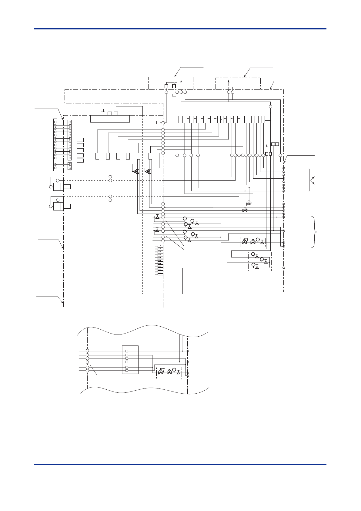
3.4 Internal Piping System Diagram
(1) GC1000D/GC1000T/GC1000W T ype X Purging
3-7
Isothermal oven
SPLIT1 Vent
B.F .1 Vent
TCD1 Vent
REF .1 Vent
SPLIT2 Vent
B.F .2 Vent
TCD2 Vent
REF .2 Vent
FID1 Vent
FID2 Vent
8
7
Programmed
temperature
oven
Sampling base
LSV2
LSV1
Explosionproof
enclosure 2
Internal pressure
detection
switch
Fan
Pressure
detection
FID1
FID2
Valve 2
TCD1
TCD2
Valve 6 Valv e 5 Valv e 4
8
7
Pressure
detection
Atomospher
pressure balancing
valve
8
8
7
7
Valve 3
Valve 1
Atomospher pressure
balancing valve
Fan
REF
Purge Purge
27
21
2223
24
Pressure
detection
16 15 14 14 13 13 12 12 11 11 10 10 9 9 8 8 7 7 6 5 4 3 2 1
24
23
12
11
10
9
8
7
14
13
1
V
2
V2
C1
F1
A1
C2
F2
A2
Restrictor 1
Restrictor 2
Restrictor 3
Restrictor 4
Restrictor 5
Restrictor 6
P
P
P
P
P
P
Flame arrester 1
Flame arrester 2
Forced cooling
valve
Cooling air
Voltex
tube
27
21
8
Atomospher pressure
balancing valve
Hydrogen
limitter
Electromagnetic
Purge for air chamber
Isothermal oven
Programed temperature oven
7
Flow rate
limitter
Cooling
Forced cooling
Explosionproof
enclosure 1
Purge
123456781314151622
Atomospher
pressure
balancing valve
P
Shut off
P
P
P
P
P
Regulator
Electric section
(pressurized enclosure)
27
Carrier
pressure
switch
Pressure regulator
21
Electromagnetic output 1
Electromagnetic output 2
Electromagnetic output 3
Electromagnetic output 4
Electromagnetic output 5
Electromagnetic output 6
Electromagnetic output 7
Electromagnetic output 8
Sample 1
Sample vent 1
Sample 2
Sample vent 2
Carrier 1
H2(N2)-1 for combustion
Air-1 for combustion
Carrier 2
H2(N2)-2 for combustion
Air-2 for combustion
H2
Air for combustion
Manifold
pressure
regulator
Purge air
To sampling system
Piping length: 10 m max.
To external
sampling
system
Samplin
base
(*)
High tempreture air
) In the case that EPC is installed.
(
*
C1
F1
A1
C2
F2
A2
Flame arrester
EPC1
EPC3
EPC5
EPC2
EPC4
EPC6
Hydrogen
limitter
Flow rate
limitter
Shut off
P
Carrier1
H2(N2)-1 for combustion
Air-1 for combustion
Carrier2
H2(N2)-2 for combustion
Air-2 for combustion
H2
Air for combustion
F0312.EPS
IM 11B03A03-01E
F0307.EPS
3rd Edition : Aug. 23. 2006-00
Page 29

<T oc> <Ind> <3. Overview >
(2) GC1000T Type Y Purging
Electric section
(pressurized enclosure)
3-8
Isothermal oven
SPLIT1 Vent
B.F .1 Vent
TCD1 Vent
REF .1 Vent
SPLIT2 Vent
B.F .2 Vent
TCD2 Vent
REF .2 Vent
FID1 Vent
FID2 Vent
8
7
Programmed
temperature
oven
Sampling base
LSV2
LSV1
Internal pressure
detection
switch
Fan
Pressure
detection
FID1
FID2
Valve 2
TCD1
TCD2
Valve 6 Valv e 5 Valv e 4
8
7
Pressure
detection
Atomospher
pressure balancing
valve
8
8
7
7
Valve 3
Valve 1
Atomospher pressure
balancing valve
Fan
REF
2223
24
Pressure
detection
16 15 14 14 13 13 12 12 11 11 10 10 9 9 8 8 7 7 6 5 4 3 2 1
24
23
12
11
10
9
8
7
14
13
1
V
2
V2
C1
F1
A1
C2
F2
A2
Restrictor 1
Restrictor 2
Restrictor 3
Restrictor 4
Restrictor 5
Restrictor 6
P
P
P
P
P
P
Flame arrester 1
Flame arrester 2
8
Atomospher pressure
balancing valve
Hydrogen
limitter
Electromagnetic
Purge for air chamber
Isothermal oven
Programed temperature oven
Forced cooling
valve
Cooling air
Voltex
tube
Cooling
Forced cooling
7
Flow rate
limitter
Atomospher
pressure
balancing valve
Shut off
P
P
Regulator
Carrier
pressure
switch
Purge
Manifold
pressure
regulator
Pressure regulator
To sampling system
Piping length: 10 m max.
Electromagnetic output 1
Electromagnetic output 2
Electromagnetic output 3
Electromagnetic output 4
Electromagnetic output 5
Electromagnetic output 6
Electromagnetic output 7
Electromagnetic output 8
Sample 1
Sample vent 1
Sample 2
Sample vent 2
Carrier 1
H2(N2)-1 for combustion
Air-1 for combustion
Carrier 2
H2(N2)-2 for combustion
Air-2 for combustion
H2
Air for combustion
To external
sampling
system
Samplin
base
(*)
123456781314151622
P
P
P
P
Purge air
High tempreture air
) In the case that EPC is installed.
(
*
C1
F1
A1
C2
F2
A2
Flame arrester
EPC1
EPC3
EPC5
EPC2
EPC4
EPC6
Hydrogen
limitter
Flow rate
limitter
Shut off
P
Carrier1
H2(N2)-1 for combustion
Air-1 for combustion
Carrier2
H2(N2)-2 for combustion
Air-2 for combustion
H2
Air for combustion
F0312.EPS
F0308.EPS
IM 11B03A03-01E
3rd Edition : Aug. 23. 2006-00
Page 30

<Toc> <Ind> <3. Overview >
(3) GC1000S/GC1000E/GC1000C Type X Pur ging, with One Protection
System
Explosionproof
enclosure 1
Electric section
(pressurized enclosure)
27
Isothermal oven
Internal pressure
detection
switch
24
REF
22
Pressure
detection
Purge
27
21
3-9
SPLIT1 Vent
B.F .1 Vent
TCD1 Vent
REF .1 Vent
F .F.1-1 Vent
F .F.1-2 Vent
TCD2 Vent
REF .2 Vent
SPLIT2 Vent
B.F .2 Vent
F .F.2-1 Vent
F .F.2-2 Vent
FID1 Vent
FID2 Vent
8
LSV2
7
LSV1
Programmed
temperature
oven
Sampling base
Fan
Pressure
detection
FID1
FID2
Methan
Converter
TCD1
TCD2
Valve 6 Valv e 5 Valv e 4
8
8
7
8
7
7
Valve 2
Valve 3
Atomospher
pressure balancing
valve
Valve 1
Atomospher pressure
balancing valve
16 15 14 14 13 13 12 12 11 11 10 10 9 9 8 8 7 7 6 5 4 3 2 1
24
12
11
10
9
8
7
14
13
1
V
2
V2
C1
F1
A1
C2
F2
A2
Restrictor 1
Restrictor 2
Restrictor 3
Restrictor 4
Restrictor 5
Restrictor 6
Restrictor 7
Restrictor 8
Restrictor 9
Restrictor 10
P
P
P
P
P
P
Flame arrester 1
Flame arrester 2
8
Atomospher pressure
balancing valve
Hydrogen
limitter
Electromagnetic
Purge for air chamber
Isothermal oven
7
Atomospher
pressure
balancing valve
P
Flow rate
Shut off
limitter
P
P
P
Manifold pressure regulator
Purge
1234567813141522
Carrier
pressure
switch
21
Pressure regulator
To sampling system
Piping length: 10 m max.
Electromagnetic output 1
Electromagnetic output 2
Electromagnetic output 3
Electromagnetic output 4
Electromagnetic output 5
Electromagnetic output 6
Electromagnetic output 7
Electromagnetic output 8
Sample 1
Sample vent 1
Sample 2
Sample vent 2
Carrier 1
H2(N2)-1 for combustion
Air-1 for combustion
Carrier 2
H2(N2)-2 for combustion
Air-2 for combustion
H2
Air for combustion
Purge air
To external
sampling
system
Samplin
base
(*)
) In the case that EPC is installed.
(
*
C1
F1
A1
C2
F2
A2
Flame arrester
EPC1
EPC3
EPC5
EPC2
EPC4
EPC6
Hydrogen
limitter
Flow rate
limitter
Shut off
P
Carrier1
H2(N2)-1 for combustion
Air-1 for combustion
Carrier2
H2(N2)-2 for combustion
Air-2 for combustion
H2
Air for combustion
F0312.EPS
IM 11B03A03-01E
F0309.EPS
3rd Edition : Aug. 23. 2006-00
Page 31
<T oc> <Ind> <3. Overview >
(4) GC1000S/GC1000E/GC1000C T ype X Purging, with Two Protection
Systems
3-10
Isothermal oven
SPLIT1 Vent
B.F .1 Vent
TCD1 Vent
REF .1 Vent
F .F.1-1 Vent
F .F.1-2 Vent
TCD2 Vent
REF .2 Vent
SPLIT2 Vent
B.F .2 Vent
F .F.2-1 Vent
F .F.2-2 Vent
FID1 Vent
FID2 Vent
8
7
Programmed
temperature
oven
LSV2
LSV1
Explosionproof
enclosure 2
Internal pressure
detection
switch
Fan
Pressure
detection
FID1
FID2
Methan
Converter
TCD1
TCD2
Valve 6 Valv e 5 Valv e 4
8
8
7
8
7
7
Valve 2
Valve 3
Atomospher
pressure balancing
valve
Valve 1
Atomospher pressure
balancing valve
REF
Purge
27
21
22
24
Pressure
detection
16 15 14 14 13 13 12 12 11 11 10 10 9 9 8 8 7 7 6 5 4 3 2 1
24
12
11
10
9
8
7
14
13
1
V
2
V2
C1
F1
A1
C2
F2
A2
Restrictor 1
Restrictor 2
Restrictor 3
Restrictor 4
Restrictor 5
Restrictor 6
Restrictor 7
Restrictor 8
Restrictor 9
Restrictor 10
P
P
P
P
P
P
Flame arrester 1
Flame arrester 2
Purge
27
21
8
Atomospher pressure
balancing valve
Hydrogen
limitter
Electromagnetic
Purge for air chamber
Isothermal oven
Explosionproof
enclosure 1
7
Atomospher
pressure
balancing valve
P
Flow rate
Shut off
limitter
P
P
P
Manifold pressure regulator
Electric section
(pressurized enclosure)
27
Carrier
pressure
switch
Purge
21
1234567813141522
Pressure regulator
To sampling system
Piping length: 10 m max.
Electromagnetic output 1
Electromagnetic output 2
Electromagnetic output 3
Electromagnetic output 4
Electromagnetic output 5
Electromagnetic output 6
Electromagnetic output 7
Electromagnetic output 8
Sample 1
Sample vent 1
Sample 2
Sample vent 2
Carrier 1
H2(N2)-1 for combustion
Air-1 for combustion
Carrier 2
H2(N2)-2 for combustion
Air-2 for combustion
H2
Air for combustion
Purge air
To external
sampling
system
Samplin
base
(*)
Sampling base
) In the case that EPC is installed.
(
*
C1
F1
A1
C2
F2
A2
Flame arrester
EPC1
EPC3
EPC5
EPC2
EPC4
EPC6
Hydrogen
limitter
Flow rate
limitter
Shut off
P
Carrier1
H2(N2)-1 for combustion
Air-1 for combustion
Carrier2
H2(N2)-2 for combustion
Air-2 for combustion
H2
Air for combustion
F0312.EPS
F0310.EPS
IM 11B03A03-01E
3rd Edition : Aug. 23. 2006-00
Page 32
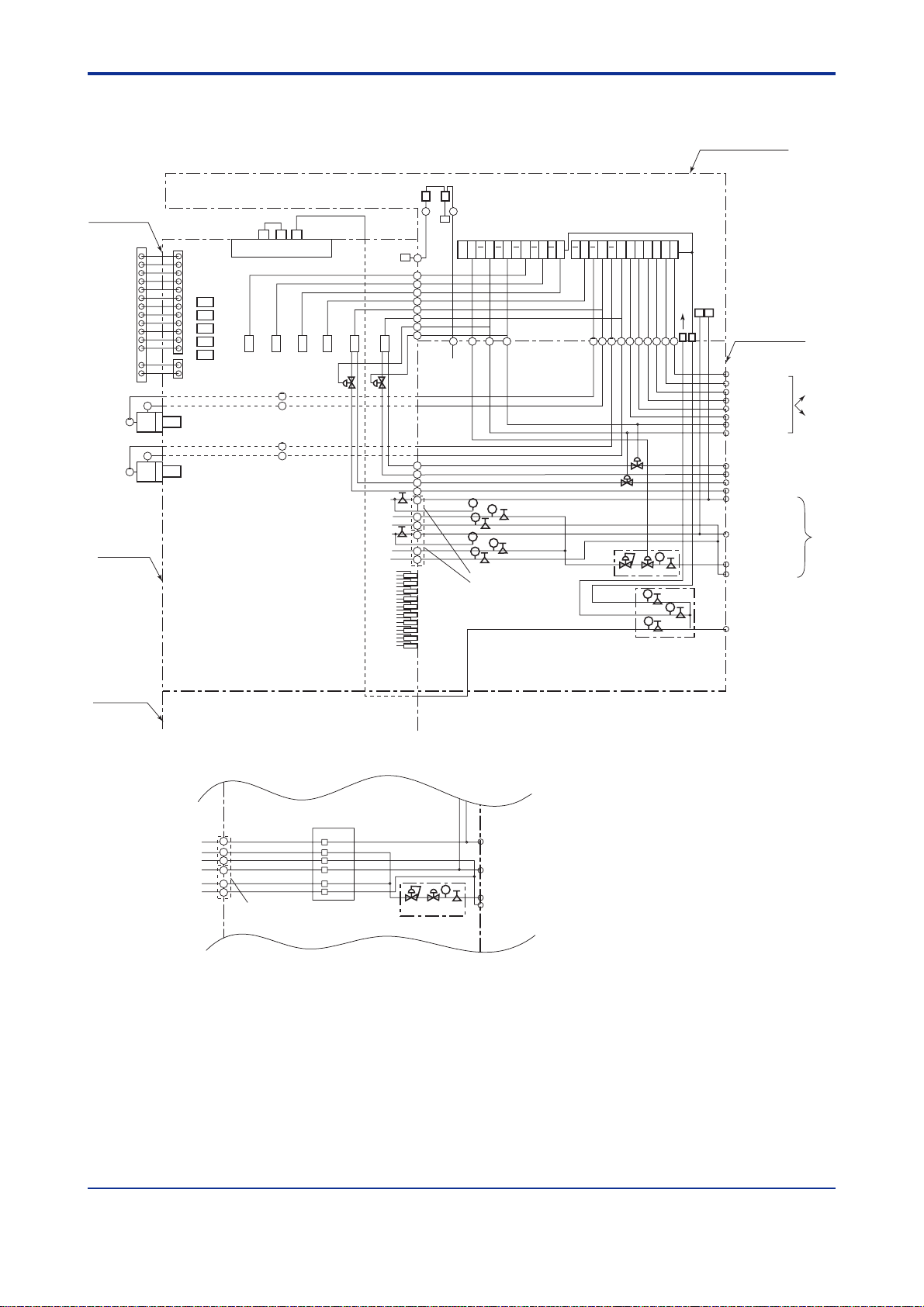
<Toc> <Ind> <3. Overview >
(5) GC1000E T ype Y Purging
Electric section
(pressurized enclosure)
3-11
Isothermal oven
SPLIT1 Vent
B.F .1 Vent
TCD1 Vent
REF .1 Vent
F .F.1-1 Vent
F .F.1-2 Vent
TCD2 Vent
REF .2 Vent
SPLIT2 Vent
B.F .2 Vent
F .F.2-1 Vent
F .F.2-2 Vent
FID1 Vent
FID2 Vent
8
7
Programmed
temperature
oven
LSV2
LSV1
Internal pressure
detection
switch
Fan
Pressure
detection
FID1
FID2
Methan
Converter
TCD1
TCD2
Valve 6 Valv e 5 Valv e 4
8
8
7
8
7
7
Valve 2
Valve 3
Atomospher
pressure balancing
valve
Valve 1
Atomospher pressure
balancing valve
REF
22
24
Pressure
detection
16 15 14 14 13 13 12 12 11 11 10 10 9 9 8 8 7 7 6 5 4 3 2 1
24
12
11
10
9
8
7
14
13
1
V
2
V2
C1
F1
A1
C2
F2
A2
Restrictor 1
Restrictor 2
Restrictor 3
Restrictor 4
Restrictor 5
Restrictor 6
Restrictor 7
Restrictor 8
Restrictor 9
Restrictor 10
P
P
P
P
P
P
Flame arrester 1
Flame arrester 2
8
Atomospher pressure
balancing valve
Hydrogen
limitter
Electromagnetic
Purge for air chamber
Isothermal oven
7
Atomospher
pressure
balancing valve
P
Flow rate
Shut off
limitter
P
P
P
Manifold pressure regulator
Purge
1234567813141522
Carrier
pressure
switch
Pressure regulator
To sampling system
Piping length: 10 m max.
Electromagnetic output 1
Electromagnetic output 2
Electromagnetic output 3
Electromagnetic output 4
Electromagnetic output 5
Electromagnetic output 6
Electromagnetic output 7
Electromagnetic output 8
Sample 1
Sample vent 1
Sample 2
Sample vent 2
Carrier 1
H2(N2)-1 for combustion
Air-1 for combustion
Carrier 2
H2(N2)-2 for combustion
Air-2 for combustion
H2
Air for combustion
Purge air
To external
sampling
system
Samplin
base
(*)
Sampling base
) In the case that EPC is installed.
(
*
C1
F1
A1
C2
F2
A2
Flame arrester
EPC1
EPC3
EPC5
EPC2
EPC4
EPC6
Hydrogen
limitter
Flow rate
limitter
Shut off
P
Carrier1
H2(N2)-1 for combustion
Air-1 for combustion
Carrier2
H2(N2)-2 for combustion
Air-2 for combustion
H2
Air for combustion
F0312.EPS
F0311.EPS
IM 11B03A03-01E
3rd Edition : Aug. 23. 2006-00
Page 33

<T oc> <Ind> <3. Overview >
3.5 External Input and Output Signals
(1)Input
Item Signal level No. Description
Analog Input
Contact Input
*1) : 2-wire transmitter
*2) : It means the data which is averaged by every 1 second
after filtered by a constant which the analog data is scanned by every 200msec. It can be output
by DCS communication (Modbus protocol).
*3) : It means the current value which is set time in a cycle time.
Isolated
4-20mA DC
1-5V DC
4-20mA DC
(with 24 or 28V DC of Power)
Specification :
5V DC, 20mA DC or more
Input
ON signal: 200Ω or less
OFF signal: 100kΩ or more
On operation:
NC or NO (selectable)
*1)
48Accuracy :
±0.5%FS (-10 to 50˚C)
Function :
Output of Current value
and Av erage value
Function :
Alarm from outside
Following command request
Stream sequence assign
Stream (cont.) assign
Stream (1 cycle) assign
Cal (Val) assign
Change of Operation mode
*2)
*3)
T0302.EPS
3-12
(2)Output
Item Signal level No. Description
Analog
Output
Contact
Output
Air output for
stream valve
*1) : Analysis result (concentration, simulated distillation result,
base level, signal level, noise level, Deviation calculation, Liner calculation1-5, Ratio,
Separation coefficient, Calorific value, Density, Compressive factor, Wobbe Index)
Isolated or No-isolated
4-20mA DC
Load: 300Ω or less
Specification (relay) :
Voltage: 30V DC
Current: 100mA DC
On operation:
NO or NC (selectable)
Air press : 350kPa
Analysis result
MAX.
36
System alarm1
8
System alarm2
Component alarm (Conc./RT)
Timing signal
Code signal for stream ID
MAX.
Binary code signal for 9 to 31 stream
(max.)
8
*1)
(Max. 5 points)
T0303.EPS
IM 11B03A03-01E
3rd Edition : Aug. 23. 2006-00
Page 34

<Toc> <Ind> <3. Overview >
(3)Communication
Item Signl level No. Description
DCS
communi-cation
Standard :
RS422 (4wires, Full-Duplex)
Specification :
Start bit 1, Stop bit 1, Parity 1, ASCII7 bit,
Without procedure or Hand shake
Speed :
1200/2400/4800/9600/19200 bps(selectable)
For explosion protection :
RS422/RS232C converter is provided.(2 wires
of power line is needed except the signal line)
The transmission type is full duplex for RS232C.
PC
communi-cation
Standard :
RS422 (4wires, Full-Duplex)
Speed :
19.6/33.6kbps
For explosion protection :
RS422/RS232C converter is provided.(2 wires
of power line is needed except the signal line)
The transmission type is full duplex for RS232C.
*1) : Analysis result(concentration, simulated distillation result,
base level, signal level, noise level, Deviation calculation, Liner calculation1-5, Ratio, Separation
coefficient, Calorific value, Density, Compressive factor, Wobbe Index)
*2) : Operation request, (Stream sequence assign, Stream
(cont.) assign, Run command, Stop command, Pause command, Range change)
*3) : Operation Information(Chromatogram, Oven
temperature, measuring stream, Valve ON/OFF etc...)
11Transmission :
Analysis result
Calibration coefficient
Alarm
Reception :
Operation request
GCMT
(GC Maintenance Terminal)
Transmission :
Analysis result
Operation information
Parameter list
Reception :
Operation request
Change of Parameter list
*4)
*5)
*4)
*5)
T0304.EPS
3-13
*6)
IM 11B03A03-01E
3rd Edition : Aug. 23. 2006-00
Page 35

Blank Page
Page 36

<Toc> <Ind> <4. Outline of Software >
4. Outline of Software
4.1 Status and Operation Mode
The GC1000 Mark II has the following statuses:
• Process: Normal measurement, calibration and validation
• Manual: Manual operation
• Lab: Measurement with automatic peak detection, like a laboratory GC
The GC1000 Mark II has the following operation modes:
• Stop: Mode in which the measurement stops
• Run: Mode in which the measurement is running
• Pause: Mode in which the measurement pauses
Figure 4.1 shows the transitions of statuses and operation modes.
4-1
Stop
command
Stop mode
Lab
Run mode
Run
command
Figure 4.1 Status and Operation Mode Transition Diagram
Pause mode Run mode Run mode
Stop command
Change the status Change the status
Process Manual
Run command
Pause command
Pause
command
Stop mode Stop mode
Run
command
Stop command
Stop
command
When the LCD panel on the GC1000 Mark II or the LCD emulator on a personal computer
(PC) connected with the GC1000 Mark II is used, by changing the operation panel to the
manual operation panel or lab operation panel, the status will change from Process to
Manual or Lab. Likewise, by changing the manual operation panel or lab operation panel
to the operation panel, the status will change from Manual or Lab to Process.
When the GCMT on a PC connected with the GC1000 Mark II is used, the status can be
changed through command button operation or menu-driven operation.
The following pages describe each status and operation in detail.
Run
command
F0401.EPS
IM 11B03A03-01E 3rd Edition : Aug. 23. 2006-00
Page 37

<T oc> <Ind> <4. Outline of Software >
4.1.1 Process
In the Process status normal process measurements, calibration, and validation are performed. When power is applied, the status enters Process.
The Process status contains the following measurement statuses.
• Stream Sequence: Continuously measures streams in order specified in Stream
Sequence
• Stream (continuous): Continuously measures the specified stream
• Stream (1 cycle): Measures the specified stream once
• Calibration/V alidation: Performs calibration or validation of the specified number
Figure 4.2 shows the transitions of measurement statuses.
4-2
Stream Sequence
(Same as the status)
Note: When Calibration/V alidation has been specified from Stream Sequence, the measurement status returns to Stream
Sequence after the completion of calibration/validation. When Calibration/Validation has been specified from Stream
(continuous), the measurement status returns to Stream (continuous) after the completion of calibration/validation.
Figure 4.2 Measurement Status Transition Diagram
Stream (coninuous)
Cal/ValStream (1 cycle) Cal/Val
F0402.EPS
The following explain each measurement status in detail.
(1) Stream Sequence
In the Stream Sequence status, the analyzer continuously measures multiple streams in
order. When power is applied, the measurement status enters Stream Sequence. Four
kinds of stream sequences can be used with the GC1000 Mark II. For each steam sequence 31 streams can be set in order. If number "0" is set as a stream number , the
measurement skips the order and goes to the stream specified in the following number.
Note that number "0" cannot be set as the first stream number, which needs any number
between 1 and 31 to be specified.
(2) Stream (continuous)
In the Stream (continuous) status, the analyzer continuously measures the specified
stream. With the GC1000 Mark II, 31 streams can be specified. In the Stream (continuous) measurement status, the analyzer measures the stream specified from among the 31
streams.
(3) Stream (1 cycle)
In the Stream (1 cycle) status, the GC1000 Mark II measures the specified stream once.
Like Stream (continuous), the analyzer measures the stream specified from among the 31
streams.
(4) Calibration/Validation
In the Calibration/V alidation status, calibration or validation is performed using a standard
sample. V alidation is to verify, using a standard sample, whether the measurement of the
GC1000 Mark II is normal. This function can be used in combination with calibration:
calibration is conducted when the increased error between a measurement result and a
standard sample is seen during the regular validation.
IM 11B03A03-01E 3rd Edition : Aug. 23. 2006-00
Page 38

<Toc> <Ind> <4. Outline of Software >
Three ways of calibration and three ways of validation can be used with the GC1000 Mark
II.
There are three methods for Calibration/V alidation: automatic, semiautomatic and manual.
The following explain the actions of three methods.
•Automatic
Calibration or validation is conducted automatically at the specified time. This function
is only available when automatic valves are used for streams for calibration or validation.
When Calibration/V alidation is set to automatic, the analyzer starts calibration or
validation at the specified starting time and subsequently conducts calibration or
validation every time after the specified interval time elapses. When the operation
mode is in Stop or Pause at the time of automatic calibration or validation, the calibration or validation for the time is cancelled.
• Semiautomatic
When the calibration number or validation number is specified, the valves for streams
for calibration or validation automatically open and the analyzer performs calibration
or validation. This function is only available when automatic valves are used for the
stream.
• Manual
4-3
When the calibration number or validation number is specified, the valves for all
streams are closed so that the analyzer is ready to allow a standard sample to flow.
The standard sample is supplied manually for displacement, making the analyzer
ready to accept a command. After the displacement is conducted adequately, the
analyzer performs calibration or validation by the start command.
Each measurement status has the following operation modes, with the exception of the
Stream (1 cycle) and Calibration/V alidation statuses which do not have Stop and Pause.
• Stop: Mode in which the measurement stops
• Run: Mode in which the measurement is running
• Pause: Mode in which the Run mode pauses
For the transitions of the operation modes, refer to Figure 4.1.
To transfer from the Run mode to the Stop mode, two commands are used: stop command
and forced stop command, which are explained below.
• Stop command
The measurement stops after an ongoing measurement has been completed.
IM 11B03A03-01E 3rd Edition : Aug. 23. 2006-00
Page 39

<T oc> <Ind> <4. Outline of Software >
The following explain each operation mode in detail.
(1) Stop
In the Stop mode the measurement stops. When power is applied, the operation mode
enters Stop. Settings should be changed in this Stop mode.
CAUTION
If settings are changed in an operation mode other than the Stop mode, the analyzer may
not accept the change and run under the previous setting.
When the operation mode is transferred to the Stop mode from others, the on-off statuses
of various valves and stream valves remains unchanged.
(2) Run
In the Run mode, the measurement runs. If the Auto Start Set is set to Enabled, the
GC1000 Mark II automatically enters the Run mode after the time set for the "Auto start
time" elapses after power is applied. When the operation mode is transferred from the
Stop mode to the Run mode, the measurement starts after the Warming up time for displacement in the sample stream elapses. For the Warming up time, see Section 4.3,
“Method”. If a level 1 alarm occurs during the Run mode, the mode changes to the Stop
mode after an ongoing measurement of the stream has been completed.
4-4
(3) Pause
In the Pause mode, the measurement pauses at the specified Pause Time. For the Pause
Time, see Section 4.3, “Method.”
When the operation mode is transferred from the Pause mode to the Run mode, the
measurement resumes at the Pause Time.
When the operation mode is transferred from the Stop mode to the Pause mode, the on-off
statuses of various valves including stream valves become those at the Pause Time of the
stream to be measured next.
IM 11B03A03-01E 3rd Edition : Aug. 23. 2006-00
Page 40

<Toc> <Ind> <4. Outline of Software >
4.1.2 Manual
In the Manual status, various operations and measurements can be performed manually .
The operations available in the Manual mode are:
• On/off of various valves
• On/off of stream valves
• On/off of several heaters
• On/off of several types of detector (only On for FID and FPD)
When the status is transferred from Process to Manual, all the various valves and stream
valves turn Off.
The Manual mode contains the following operation modes.
• Stop: Mode in which measurement stops
• Run: Mode in which measurement runs
For the transitions of the operation modes, refer to Figure 4.1.
The following explain each operation mode in detail.
(1) Stop
In the Stop mode the manual measurement stops.
4-5
4.1.3 L a b
(2) Run
In the Run mode the manual measurement runs. During the Run mode, the GC1000 Mark
II detects peaks automatically until the mode turns to Stop. When the mode turns to Stop,
the concentration in area percentage is calculated from the area of peaks detected. The
calculated concentration values are displayed on the Laboratory Analysis Results display
panel. For five seconds after the operation mode turns from Run to Stop, the GC1000
Mark II does not accept the run command in order to process analysis calculations and
others.
In the Lab status the lab measurement runs. The GC1000 Mark II performs continuous
measurements for times specified in the lab settings.
In the Run mode in Process, peaks are detected according to the on/off of the set gate,
while in Lab, peaks are detected automatically like a laboratory GC. This mode can be
used for determining gate timing when a column system is changed.
The Lab mode contains the following operation modes.
• Stop: Mode in which measurement stops
• Run: Mode in which measurement runs
For the transitions of the operation modes, refer to Figure 4.1.
The following explain each operation mode in detail.
(1) Stop
In the Stop mode the lab measurement stops.
(2) Run
In the Run mode the lab measurement runs. In the Run mode, GC1000 Mark II performs
measurements according to the lab settings. If a level 1 alarm occurs during the Run
mode, the mode changes to the Stop mode after an ongoing lab measurement has been
completed.
IM 11B03A03-01E 3rd Edition : Aug. 23. 2006-00
Page 41

<T oc> <Ind> <4. Outline of Software >
4.2 Stream
In the GC1000 Mark II, 31 streams can be used. Parameters needed to be specified for
streams are:
• Stream valve number
Any one stream valve number from among the numbers of 1 to 31 should be specified for a
stream.
If the stream valves are automatic, the stream valve of the specified valve turns on/off. If
the stream valves are manual, this setting does not have any effect on the operation.
The same stream valve number can be specified for different streams. When multiple
measurements are performed in one stream, the same stream valve number should be
specified.
A standard sample stream should be specified as one of the streams.
• Method number
Any number from 1 to 4 should be specified for a method number.
There are three types for the stream:
• Measurement stream
4-6
Used for measuring process samples.
• Validation stream
Comparing measured results before and after calibration, or checking if the GC1000 Mark
II is operating properly can be performed using a standard sample. The validation stream
is used for standard sample measurement in such case.
• Calibration stream
Used for measuring a standard sample at calibration. The calibration stream may be used
in combination with the validation stream.
IM 11B03A03-01E 3rd Edition : Aug. 23. 2006-00
Page 42

<Toc> <Ind> <4. Outline of Software >
4.3 Method
Activation timing for various valves and parameters with regard to the temperature of the
isothermal/programmed-temperature ovens should be specified for Method. Four Methods
can be used with the GC1000 Mark II. Parameters needed to be specified are described
below. For setting procedures, refer to the LCD Panel Operation Manual, IM 11B03A03-05
E.
• Analysis cycle
Time from start (0 second) to stop of analysis
• Warming up time
Time required for displacement in sample streams. An appropriate displacement time
should be determined considering the diameter and length of the sample stream tubing,
sample flow rate and delay time.
A positive value should be specified for the W arming up time. But displacement in sample
streams is implemented before the start of analysis (0 second) so that the Warming up time
actually acts as a negative value.
• Peak detection stop time
Time to stop peak detection compulsorily, which is usually specified to around five seconds
earlier than the pause time. The time must be the analysis cycle time minus one second, or
less.
4-7
In case of the GC1000D/GC1000T/GC1000W, the heater should be turned of f at the time
of peak detection stop time.
• Pause time
Time when the GC1000 Mark II can be stopped without adversely affecting the column
system. Usually the pause time should be set after peaks of all components have been
eluted (after the peak detection stop time) for the analysis cycle time minus 3 seconds, or
less.
• DO on time/DO off time
These can be used for notifying a supervisory computer or system of analysis end timing
and other information by using contacts. They can also be used as a reading signal when
analog outputs are employed.
• Stream valve on time/stream valve off time
Time to turn on/off stream valves. As stream valves usually turns on from the Warming up
time, the stream valve on time should be set as a negative value. The values to be set
should be the Warming up time minus one second, or more, and the analysis cycle time
minus two seconds, or less.
• V1 to V8 on/off time
Time to turn on/off valve 1 to valve 8 - sample valves, back flush valves, column switching
valves, and atmosphere balance valves. On/off can be set for three times each. The time
to be set should be the Warming up time minus one second, or more, and the Analysis
Cycle Time minus two seconds, or less.
• Initial control temperature
Displayed on the GC1000D/GC1000T/GC1000W that uses a temperature program. The
temperature of the programmed-temperature oven at the start of analysis should be specified.
• Initial temperature time
Displayed on the GC1000D/GC1000T/GC1000W that uses a temperature program. The
time for holding the initial control temperature should be specified.
IM 11B03A03-01E
3rd Edition : Aug. 23. 2006-00
Page 43
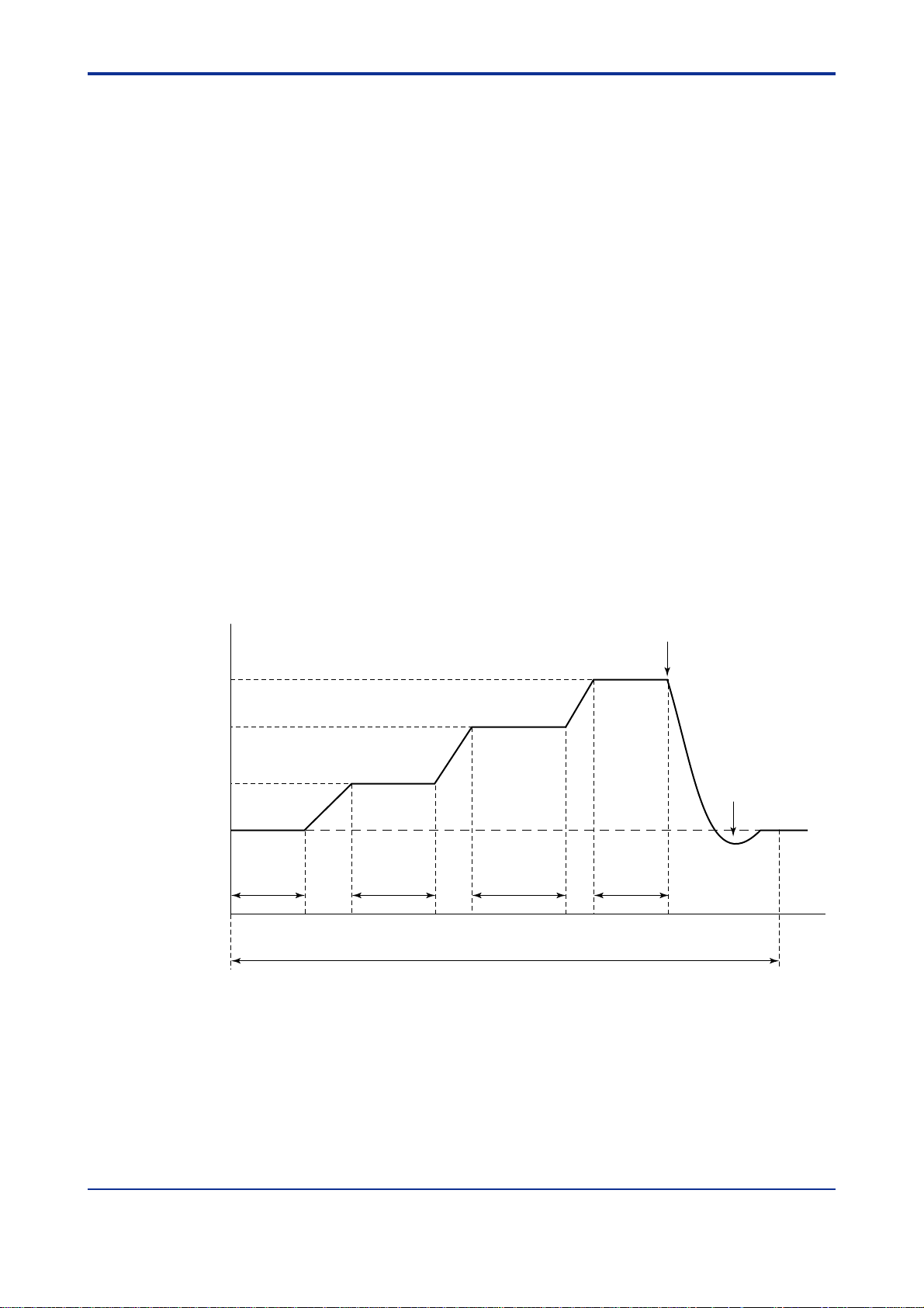
<T oc> <Ind> <4. Outline of Software >
• The first temperature gradient/first control temperature/fir st temperature time (only for the
GC1000D/GC1000T/GC1000W)
• The second temperature gradient/second control temperature/second temperature
time (only for the GC1000D/GC1000T/GC1000W)
• The thir d temperature gradient/third contr ol temperature /thir d temperature time
(only for the GC1000D/GC1000T/GC1000W)
• Initial control pressure
Displayed when EPC is installed that uses a pressure program. The pressure at the
start of analysis should be specified.
• Initial pressure time
Displayed when EPC is installed that uses a pressure program. The time for holding
the initial control pressure should be specified.
• First pressure gradient/first control pressure/fir st control time (only when EPC is
installed)
• Second pressure gradient/second control pressure/second control time (only when
EPC is installed)
• Thir d pressure gradient/third contr ol pressure/thir d control time (onl y when EPC is
installed)
4-8
In the GC1000D/GC1000T/GC1000W, three stages of temperature program can be specified. Figure 4.3 shows the operations for temperature programs.
Temperature
Third control
temperature
Second control
temperature
First control
temperature
Initial control
temperature
Figure 4.3 Operation for Temperature Programs
First
temperature
gradient
Initial
temperature
time
Second
temperature
gradient
First
temperature
time
Third
temperature
gradient
Second
temperature
time
Analysis cycle
End of peak detection
time
Heater off
Third
temperature
time
Heater on
Analysis endAnalysis start
Time
F0403.EPS
IM 11B03A03-01E
3rd Edition : Aug. 23. 2006-00
Page 44

<Toc> <Ind> <4. Outline of Software >
In the case that EPC is installed, three stages of pressure program can be specified.
Figure 4.4 shows the operations for EPC pressure programs.
4-9
Pressure
Third control
pressure
Second control
pressure
First control
pressure
Initial control
pressure
Figure 4.4 Operation for EPC Pressure Programs
First
pressure
gradient
Initial
control
time
Second
pressure
gradient
First
control
time
Analysis cycle
Third
pressure
gradient
Second
control
time
End of peak detection
time
Third
control
time
Analysis endAnalysis start
Time
F0404.EPS
4.4 Description of Actions
Actions under the conditions below - stream sequence in Table 4.1, calibration in Table 4.2,
and validation in Table 4.3 - are described as examples.
T able 4.1
First stream
number
Stream Sequnce 1 Stream 1 Stream 2 Stream 3 0
Stream Sequnce 2 Stream 4 0 Stream 5 Stream 6
T able 4.2
Calibration
stream number
Calibration 1 Stream 7 2 Stream 8
T able 4.3
Validation
stream number
Validation 1 Stream 9 2
Second stream
number
Measuring
times
Measuring
times
T0403.EPS
Third stream
number
Validation
stream number
T0402.EPS
Fourth stream
number
T0401.EPS
IM 11B03A03-01E
3rd Edition : Aug. 23. 2006-00
Page 45

<T oc> <Ind> <4. Outline of Software >
4.4.1 Actions of Stream Sequence
The same action is performed when the Stream Sequence is specified at any timing during
analysis.
(1) An action when the operation mode is transferred from Stop to Run while the mea-
surement status is in Stream Sequence 1, is shown in Figure 4.5.
Run command
S1 S2 S3 S1 S2 S3
W2 W3 W1 W2 W3 W1W1
Time
Stream Sequence 1
S1 to S3: Analysis cycles for streams 1 to 3
W1 to W3: Warming up time for streams 1 to 3
Figure 4.5 Action of Stream Sequence (1)
(2) An action when Stream Sequence 2 is specified while the measurement status is in
Stream Sequence 1 and the operation mode is in Run, is shown in Figure 4.6.
4-10
F0405.EPS
Selet the Stream Sequence 2
S1 S2 S5
W4
Time
Stream Sequence 1 Stream Sequence 2
S1 to S6: Analysis cycles for streams 1 to 6
W1 to W6: Warming up time for streams 1 to 6
S4 S6 S4
W5 W6 W4 W5W2
F0406.EPS
Figure 4.6 Action of Stream Sequence (2)
(3) An action when Stream Sequence 1 is specified while the measurement status is in
Stream (continuous) 2 and the operation mode is in Run, is shown in Figure 4.7.
Select the Stream Sequence 1
S2 S2 S2
W1
Time
Stream (Cont) 2 Stream Sequence 1
S1 S3 S1
W2 W3 W1 W2W2
S1 to S3: Analysis cycles for streams 1 to 3
W1 to W3: Warming up time for streams 1 to 3
F0407.EPS
Figure 4.7 Action of Stream Sequence (3)
(4) When Stream Sequence 1 is specified while the measurement status is in Stream
Sequence 2 to 4 or in Stream (continuous) 1 to 31 and the operation mode is in Stop
or in Pause, the measurement status is immediately changed to Stream Sequence 1
and the operation mode to Stop. The same action is performed when Stream Sequence 2 to 4 is specified.
IM 11B03A03-01E
3rd Edition : Aug. 23. 2006-00
Page 46

<Toc> <Ind> <4. Outline of Software >
4.4.2 Actions of Stream (Continuous)
Actions are different according to the timing when Stream (continuous) is specified.
(1) An action when the operation mode is transferred from Stop to Run while the mea-
surement status is in Stream (continuous) 2 and the operation mode is in Stop, is
shown in Figure 4.8.
Run command
S2 S2 S2 S2 S2 S2
W2 W2 W2 W2 W2 W2W2
Time
Stream (Cont) 2
S2: Analysis cycles for stream 2
W2: Warming up time for stream 2
Figure 4.8 Action of Stream (Continuous) (1)
(2) An action when Stream (continuous) 3 is specified before the following warming up
time starts while the measurement status is in Stream (continuous) 2 and the operation mode is in Run (i.e., Stream 2 is being measured), is shown in Figure 4.9.
4-11
F0408.EPS
Select the Stream (cont) 3
S2S2 S2 S3 S3 S3 S3
W2 W3 W3 W3 W3 W3W2
Time
Stram (Cont) 2
S2, S3: Analysis cycles for streams 2 and 3
W2, W3: Warming up time for streams 2 and 3
Stream (Cont) 3
F0409.EPS
Figure 4.9 Action of Stream (Continuous) (2)
(3) An action when Stream (continuous) 3 is specified after the following warming up time
has started while the measurement status is in Stream (continuous) 2 and the operation mode is in Run (i.e., Stream 2 is being measured), is shown in Figure 4.10.
Select the Stream (cont) 3
S2S2 S2 S2 S3 S3 S3
W2 W2 W3 W3 W3 W3W2
Time
Stram (Cont) 2
Stram (Cont) 3
S2, S3: Analysis cycles for streams 2 and 3
W2, W3: Warming up time for streams 2 and 3
Figure 4.10 Action of Stream (Continuous) (3)
IM 11B03A03-01E
F0410.EPS
3rd Edition : Aug. 23. 2006-00
Page 47

<T oc> <Ind> <4. Outline of Software >
(4) An action when Stream (continuous) 4 is specified while the measurement status is in
Stream Sequence 1 and the operation mode is in Run, is shown in figure 4.1 1.
Select the Stream (cont) 4
4-12
S1 S2 S4
W4
Time
Stream Sequence 1 Stream (Cont) 4
S1 to S4: Analysis cycles for streams 1 to 4
W1 to W4: Warming up time for streams 1 to 4
S4 S4 S4
W4 W4 W4 W4W2
F0411.EPS
Figure 4.11 Action of Stream (Continuous) (4)
(5) When stream (continuous) 1 is specified while the measurement status is in Stream
Sequence 1 to 4 or in Stream (continuous) 2 to 31 and the operation mode is in Stop
or in Pause, the measurement status is immediately changed to Stream (continuous)
1 and the operation mode to Stop. The same action is performed when Stream
(continuous) 2 to 31 is specified.
IM 11B03A03-01E
3rd Edition : Aug. 23. 2006-00
Page 48
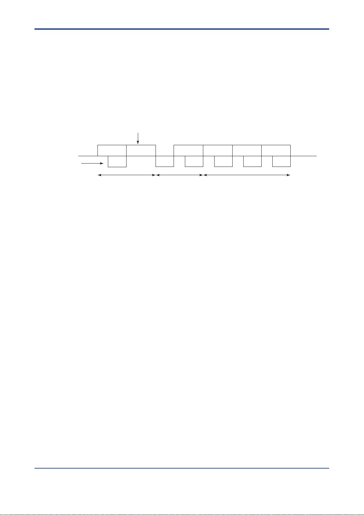
<Toc> <Ind> <4. Outline of Software >
4.4.3 Actions of Stream (1 cycle)
Stream (1 cycle) 1 to 31 is allowed to be specified only when the measurement status is in
Stream Sequence 1 to 4. The same action is performed when the Stream (1 cycle) is
specified at any timing during analysis.
(1) When Stream (1 cycle) 1 to 31 is specified while the measurement status is in Stream
Sequence 1 to 4 and the operation mode is in Stop or in Pause, the specified stream
is measured once and then the measurement status turns to Stream Sequence 1 and
the operation mode returns to Stop.
(2) An action when Stream (1 cycle) 4 is specified while the measurement status is in
Stream Sequence 1 and the operation mode is in Run, is shown in Figure 4.12.
Select the Stream (1 cycle) 4
4-13
S1 S2 S3
W4
Time
Stream Sequence 1 Stream Sequence 1Stream (1 cycle) 4
S1 to S4: Analysis cycles for streams 1 to 4
W1 to W4: Warming up time for streams 1 to 4
Figure 4.12 Action of Stream (1 cycle)
S4 S1 S2
W3 W1 W2 W3W2
F0412.EPS
IM 11B03A03-01E
3rd Edition : Aug. 23. 2006-00
Page 49

<T oc> <Ind> <4. Outline of Software >
4.4.4 Actions of Calibration
Calibration 1 to 3 is allowed to be specified only when the measurement status is in Stream
Sequence 1 to 4 or in Stream (continuous) 1 to 4. Actions are dif ferent according to the
specified calibration (validation) method.
• Automatic Calibration
The same action is performed when the starting time comes at any timing during analysis.
(1) An action when the starting time of Automatic Calibration 1 comes while the measure-
ment status is in Stream Sequence 1 and the operation mode is in Run, is shown in
Figure 4.13.
Starting time of Automatic Calibration 1
4-14
S1 S2 S7
W7
Time
Stream Sequence 1 Stream Sequence 1Calibration 1
S1 to S8: Analysis cycles for streams 1 to 8
W1 to W8: Warming up time for streams 1 to 8
S7 S8 S3
W7 W8 W3 W1W2
F0413.EPS
Figure 4.13 Action of Automatic Calibration (1)
(2) An action when the starting time of Automatic Calibration 1 comes while the measure-
ment status is in Stream (continuous) 1 and the operation mode is in Run, is shown in
Figure 4.14.
Starting time of Automatic Calibration 1
S1 S1 S7
W7
Time
Stream (Cont) 1 Stream (Cont) 1Calibration 1
S1 to S8: Analysis cycles for streams 1 to 8
W1 to W8: Warming up time for streams 1 to 8
Figure 4.14 Action of Automatic Calibration (2)
S7 S8 S1
W7 W8 W1 W1W1
F0414.EPS
IM 11B03A03-01E
3rd Edition : Aug. 23. 2006-00
Page 50
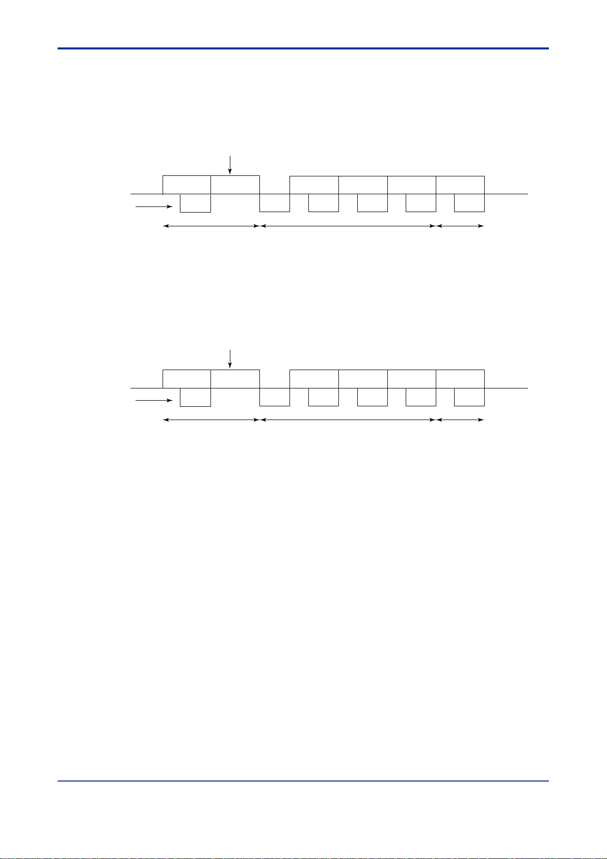
<Toc> <Ind> <4. Outline of Software >
• Semiautomatic Calibration
The same action is performed when the calibration is specified at any timing during analysis.
(1) An action when Calibration 1 is specified while the measurement status is in Stream
Sequence 1 and the operation mode is in Run, is shown in Figure 4.15.
Select the Calibration 1
4-15
S1 S2 S7
W7
Time
Stream Sequence 1 Stream Sequence 1Calibration 1
S1 to S8: Analysis cycles for streams 1 to 8
W1 to W8: Warming up time for streams 1 to 8
S7 S8 S3
W7 W8 W3 W1W2
F0415.EPS
Figure 4.15 Action of Semiautomatic Calibration (1)
(2) An action when calibration 1 is specified while the measurement status is in Stream
(continuous) 1 and the operation mode is in Run, is shown in Figure 4.16.
Select the Calibration 1
S1 S1 S7
W7
Time
Stream (Cont) 1 Stream (Cont) 1Calibration 1
S1 to S8: Analysis cycles for streams 1 to 8
W1 to W8: Warming up time for streams 1 to 8
Figure 4.16 Action of Semiautomatic Calibration (2)
S7 S8 S1
W7 W8 W1 W1W1
F0416.EPS
(3) When Calibration 1 is specified while the measurement status is in Stream Sequence
1 to 4 or in Stream (continuous) 1 to 31 and the operation mode is in Stop or in Pause,
the measurement status is immediately changed to Calibration 1 and then Calibration
1 is performed. After Calibration 1 has been completed, the previous measurement
status is retrieved and the operation mode turns to Stop. The same action is performed when Calibration 1 or 2 is specified.
IM 11B03A03-01E
3rd Edition : Aug. 23. 2006-00
Page 51

<T oc> <Ind> <4. Outline of Software >
• Manual Calibration
The same action is performed when the calibration is specified at any timing during analysis.
(1) An action when Calibration 1 is specified while the measurement status is in Stream
Sequence 1 and the operation mode is in Run, is shown in Figure 4.17. After Calibration 1 has been completed, the measurement status returns to Stream Sequence 1
and the operation mode turns to Stop.
Finishing the calibrationSelect the Calibration 1
Starting the calibration
4-16
S1 S7
TE TE
Time
Stream Sequence 1 Stream Sequence 1Calibration 1
S1 to S8: Analysis cycles for streams 1 to 8
W1 to W8: Warming up time for streams 1 to 8
TE: Displacement enabled (repeat of 20-second cycle)
S7 S8
W7 W8W7
F0417.EPS
Figure 4.17 Action of Manual Calibration (1)
(2) An action when Calibration 1 is specified while the measurement status is in Stream
Sequence (continuous) 1 and the operation mode is in Run, is shown in Figure 4.18.
After Calibration 1 has been completed, the measurement status returns to Stream
(continuous) 1 and the operation mode turns to Stop.
Finishing the calibrationSelect the Calibration 1
Starting the calibration
S1 S7
TE TE
Time
Stream (Cont) 1 Stream (Cont) 1Calibration 1
S7 S8
W7 W8W7
S1 to S8: Analysis cycles for streams 1 to 8
W1 to W8: Warming up time for streams 1 to 8
TE: Displacement enabled (repeat of 20-second cycle)
F0418.EPS
Figure 4.18 Action of Manual Calibration (2)
(3) When calibration 1 is specified while the measurement status is in Stream Sequence
1 to 4 or in Stream (continuous) 1 to 31 and the operation mode is in Stop or in Pause,
displacement become available immediately . The following actions are the same as
those described in (1) or (2). Refer to the action after the start of calibration in Figure
4.17 or Figure 4.18. The same action is performed when Calibration 2 or 3 is specified.
IM 11B03A03-01E
3rd Edition : Aug. 23. 2006-00
Page 52
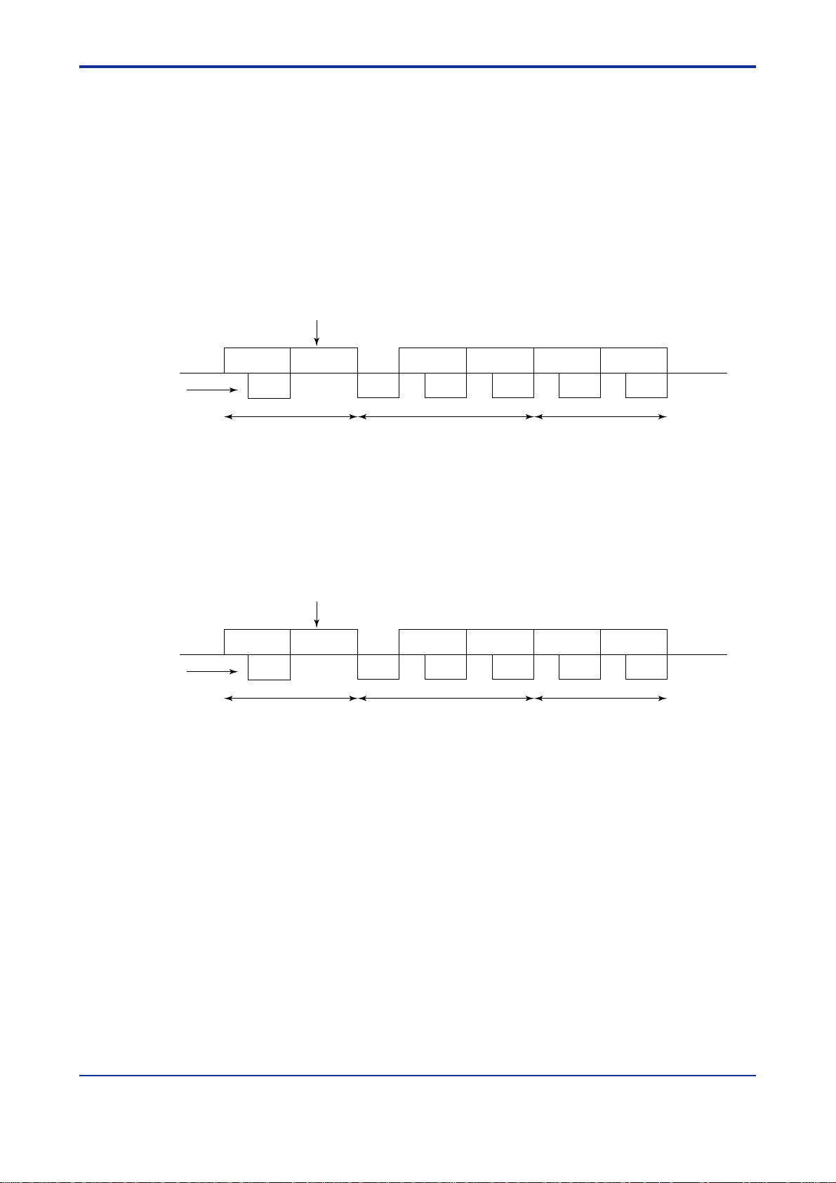
<Toc> <Ind> <4. Outline of Software >
4.4.5 Actions of Validation
V alidation 1 to 3 is allowed to be specified only when the measurement status is in Stream
Sequence 1 to 4 or in Stream (continuous) 1 to 31. Actions are dif ferent according to
settings. The same action is performed when the starting time comes at any timing during
analysis.
• Automatic V alidation
(1) An action when the starting time of Automatic Validation 1 comes while the measure-
ment status is in Stream Sequence 1 and the operation mode is in Run, is shown in
Figure 4.19.
Starting time of Automatic Validation 1
4-17
S1 S2 S9
W9
Time
Stream Sequence 1 Stream Sequence 1Validation 1
S1 to S9: Analysis cycles for streams 1 to 9
W1 to W9: Warming up time for streams 1 to 9
S9 S3 S1
W9 W3 W1 W2W2
F0419.EPS
Figure 4.19 Action of Automatic Validation (1)
(2) An action when the starting time of Automatic Validation 1 comes while the measure-
ment status is in Stream (continuous) 1 and the operation mode is in Run, is shown in
Figure 4.20.
Starting time of Automatic Validation 1
S1 S1 S9
W9
Time
Stream (Cont) 1 Stream (Cont) 1Validation 1
S1, S9: Analysis cycles for streams 1 and 9
W1, W9: Warming up time for streams 1 and 9
Figure 4.20 Action of Automatic Validation (2)
S9 S1 S1
W9 W1 W1 W1W1
F0420.EPS
IM 11B03A03-01E
3rd Edition : Aug. 23. 2006-00
Page 53

<T oc> <Ind> <4. Outline of Software >
• Semiautomatic Validation
The same action is performed when the validation is specified at any timing during analysis.
(1) An action when V alidation 1 is specified while the measurement status is in Stream
Sequence 1 and the operation mode is in Run, is shown in Figure 4.21.
Select the Validation 1
4-18
S1 S2 S9
W9
Time
Stream Sequence 1 Stream Sequence 1Validation 1
S1 to 9: Analysis cycles for streams 1 to 9
W1 to W9: Warming up time for streams 1 to 9
S9 S3 S1
W9 W3 W1 W2W2
F0421.EPS
Figure 4.21 Action of Semiautomatic Validation (1)
(2) An action when V alidation 1 is specified while the measurement status is in Stream
(continuous) 1 and the operation mode is in Run, is shown in Figure 4.22.
Select the Validation 1
S1 S1 S9
W9
Time
Stream (Cont) 1 Stream (Cont) 1Validation 1
S1, 9: Analysis cycles for streams 1 and 9
W1, W9: Warming up time for streams 1 and 9
Figure 4.22 Action of Semiautomatic Validation (2)
S9 S1 S1
W9 W1 W1 W1W1
F0422.EPS
(3) When V alidation 1 is specified while the measurement status is in Stream Sequence 1
to 4 or in Stream (continuous) 1 to 31 and the operation mode is in Stop or in Pause,
the measurement status is immediately changed to V alidation 1 and then Validation 1
is performed. After Validation 1 has been completed, the previous measurement
status is retrieved and the operation mode turns to Stop. The same action is performed when V alidation 2 or 3 is specified.
IM 11B03A03-01E
3rd Edition : Aug. 23. 2006-00
Page 54

<Toc> <Ind> <4. Outline of Software >
• Manual Validation
The same action is performed when the validation is specified at any timing during analysis.
(1) An actin when V alidation 1 is specified while the measurement status is in Stream
Sequence 1 and the operation mode is in Run, is shown in Figure 4.23. After Validation 1 has been completed, the measurement status returns to Stream Sequence 1
and the operation mode turns to Stop.
Finishing the validationSelect the Validation 1
Starting the validation
4-19
S1 S9
TE TE
Time
Stream Sequence 1 Stream Sequence 1Validation 1
S1 to S9: Analysis cycles for streams 1 to 9
W1 to W9: Warming up time for streams 1 to 9
TE: Displacement enabled (repeat of 20-second cycle)
S9
W9W9
F0423.EPS
Figure 4.23 Action of Manual Validation (1)
(2) An action when V alidation 1 is specified while the measurement status is in Stream
(continuous) 1 and the operation mode is in Run, is shown in Figure 4.24. After
V alidation 1 has been completed, the measurement status returns to stream (continuous) 1 and the operation mode turns to Stop.
Starting the validation
S1 S9
TE TE
Time
Stream (Cont) 1 Stream (Cont) 1Validation 1
S9
W9W9
Finishing the validationSelect the Validation 1
S1, 9: Analysis cycles for streams 1 and 9
W1, W9: Warming up time for streams 1 and 9
TE: Displacement enabled (repeat of 20-second cycle)
F0424.EPS
Figure 4.24 Action of Manual Validation (2)
(3) When V alidation 1 is specified while the measurement status is in Stream Sequence 1
to 4 or in Stream (continuous) 1 to 31 and the operation mode is in Stop or in Pause,
displacement become available immediately . The following actions are the same as
those described in (1) or (2). Refer to the action after the start of validation in Figure
4.23 or Figure 4.24. The same action is performed when V alidation 2 or 3 is specified.
IM 11B03A03-01E
3rd Edition : Aug. 23. 2006-00
Page 55

<T oc> <Ind> <4. Outline of Software >
4.5 Computation and Processing
The following are processed using chromatograms obtained as detection signals. For the
setting procedure, see the LCD Panel Operation Manual, IM 1 1B03A03-05E.
• Peak processing
• Deviation processing
• Additional processing
• Signal processing
Each processing is outlined below. For details, see the Technical Guide, IM 11B03A03-03E.
4.5.1 Peak Processing
This processing detects peaks from a detector signal and determines the concentrations of
components based on the area or height of each peak. The retention times, peak half-width
and so on are also determined from the detected peaks.
4.5.2 Deviation processing
This processing determines the value obtained by subtracting the sum of the concentrations of components computed by peak processing from the total sum of set concentrations.
4-20
4.5.3 Additional processing
There are the following three types of processing in the additional processing:
• Linear computation processing
This processing determines the total sum of the concentrations of each component
computed in the peak processing multiplied by individual coefficients.
• Ratio computation processing
This processing determines the ratio of concentrations of two components obtained
by the peak processing.
• Separation capability processing
This processing determines the separation capability using retention time and peak
half-widths of two adjacent components determined by the peak processing.
IM 11B03A03-01E
3rd Edition : Aug. 23. 2006-00
Page 56

<Toc> <Ind> <4. Outline of Software >
4.5.4 Signal Processing
There are three types of processing in the signal processing:
• Base level processing
The detector signal at a time set for base level processing within the analysis cycle
avoiding component signals is used as the base level value. If the base level processing is not set, the detector signal immediately after the start of analysis is employed as
the base level value.
• Signal level processing
The differences between the detector signals at each time set for signal level process-
ing within the analysis cycle and the base level value, are used as the signal level
values. If more than one base level processing is set, the base level value immediately before a base level processing is used for signal level processing.
• Noise level processing
Among the preceding 20 data for detector signals at a time set for noise level process-
ing within the analysis cycle, the maximum and minimum values are used as noise
level values.
4-21
IM 11B03A03-01E
3rd Edition : Aug. 23. 2006-00
Page 57

<T oc> <Ind> <4. Outline of Software >
4.6 Alarm Processing
There are four alarm levels. For details of alarms, see the Alarm Message Manual, IM
1 1B03A03-06E.
• Level 1
Alarms for system or hardware failures. When an alarm is generated, the alarm
condition is maintained until it is reset.
If a level-1 alarm is generated in the Run or Lab mode, the operation mode changes to
Stop at the end of the measurement being executed.
• Level 2
Alarms for measuring conditions failure.
When an alarm is generated, the alarm condition is maintained until it is reset.
• Component
Alarms when measurement results such as concentrations and retention times be-
come out of each specified range.
If an alarm is generated, the alarm condition is maintained until it is reset.
• Level 3
4-22
Alarms for minor failures or information other than level-1 and level-2 alarms.
The alarm condition is not maintained.
IM 11B03A03-01E
3rd Edition : Aug. 23. 2006-00
Page 58

<Toc> <Ind> <5. Actions of External Input and Output Signals >
5-1
5. Actions of External Input and Output Signals
5.1 Analog Hold Output
Up to 36 outputs are available as option.
Actions of analog hold output are different between when the actual stream is specified and
when "99" is specified for the stream number in setting analog hold output. Actions of
contact output are different whether a contact output is used or not as a stream identification signal. The following explains actions of analog output as well as contact output. If
"99" is specified for the stream number, contact output must be used as a stream identification signal. For actions of contact output other than stream identification signals, refer to
Section 5.2, “Contact Output.”
IM 11B03A03-01E 3rd Edition : Aug. 23. 2006-00
Page 59

<T oc> <Ind> <5. Actions of External Input and Output Signals >
5.1.1 When Actual Stream is Specified for Stream Number (without Stream Identification Signal)
An action when analog hold output is specified as shown in Table 5.1, is illustrated in Figure
5.1.
Table 5.1 Setting of Analog Output
Output stream #1
CH.1
CH.2
CH.3
CH.4
CH.5
CH.6
CH.7
CH.8
Output peak #1
1
1
1
1
2
2
2
2
1
2
3
4
1
2
3
4
Output stream #2
None
None
None
None
None
None
None
None
Output peak #2
None
None
None
None
None
None
None
None
T0501.EPS
5-2
Stream 1
End of Analysis
*1 *1 *1 *1
CH.1
CH.2
Analog Hold Output
CH.3
CH.4
CH.5
CH.6
CH.7
CH.8
End of Analysis: Time when the final peak detection is completed or peak detection stop time.
*1: One to two seconds (depending on analysis specifications)
Figure 5.1 Action of Analog Output
Stream 2
End of Analysis
Stream 1
End of Analysis
Stream 2
End of Analysis
F0501.EPS
IM 11B03A03-01E 3rd Edition : Aug. 23. 2006-00
Page 60

<Toc> <Ind> <5. Actions of External Input and Output Signals >
5.1.2 When Actual Stream is Specified for Stream Number (with Stream Identification Signal)
An action when analog hold output is specified as shown in Table 5.2, is illustrated in Figure
5.2.
Table 5.2 Setting of Analog Output
Output stream #1
CH.1
CH.2
CH.3
CH.4
Output peak #1
1
1
1
1
1
2
3
4
Output stream #2
2
2
2
2
Output peak #2
1
2
3
4
T0502.EPS
5-3
Stream 1
End of Analysis
Analog Hold Output Contact Output
CH.1
CH.2
CH.3
CH.4
CH.3
(Read-in signal)
CH.4
(Read-in signal)
CH.5
(Read-in signal)
End of Analysis: Time when the final peak detection is completed or peak detection stop time.
*1: One to two seconds (depending on analysis specifications)
*1 2s4s 2s4s 2s4s 2s4s*1 *1 *1
Stream 2
End of Analysis
Figure 5.2 Actions of Analog Output and Contact Output
Stream 1
End of Analysis
Stream 2
End of Analysis
F0502.EPS
IM 11B03A03-01E 3rd Edition : Aug. 23. 2006-00
Page 61

<T oc> <Ind> <5. Actions of External Input and Output Signals >
5.1.3 When "99" is Specified for Stream Number (with Stream Identification Signal)
An action when analog hold output is specified as shown in Table 5.4 under the peak
setting conditions of each stream as shown in Table 5.3, is illustrated in Figure 5.3.
Table 5.3 Conditions of Peaks for Streams
Stream 1
Peak 1
Peak 2
Peak 3
Peak 4
Exist
Exist
Exist
Exist
Table 5.4 Setting of Analog Output
Output stream #1
CH.1
CH.2
CH.3
CH.4
99
99
99
99
Stream 2
Exist
None
Exist
None
Output peak #1
Stream 3
Exist
Exist
None
Exist
T0503.EPS
1
2
3
4
Output stream #2
None
None
None
None
Output peak #2
None
None
None
None
T0504.EPS
5-4
Stream 1
End of Analysis
Analog Hold Output Contact Output
CH.1
CH.2
CH.3
CH.4
CH.3
(Read-in signal)
CH.4
(Read-in signal)
CH.5
(Read-in signal)
End of Analysis: Time when the final peak detection is completed or peak detection stop time.
*1: One to two seconds (depending on analysis specifications)
*1 2s4s 2s4s 2s4s 2s4s*1 *1 *1
Stream 2
End of Analysis
Figure 5.3 Actions of Analog Output and Contact Output
Stream 1
End of Analysis
Stream 2
End of Analysis
F0503.EPS
IM 11B03A03-01E 3rd Edition : Aug. 23. 2006-00
Page 62

<Toc> <Ind> <5. Actions of External Input and Output Signals >
5.2 Contact Output
The following five types can be specified for up to eight contact outputs as standard.
• Stream Sequence
• Stream
• Operation Mode
• Alarm
• Timing
Actions when each type is specified, are described below.
CAUTION
If settings are changed in the DO Setup panel while the contact output is On, the contact
output may remain unchanged in On until the power is turned off and on. In changing
settings, make sure that the contact output is Off.
5-5
5.2.1 Stream Sequence
When the stream sequence with the number specified in the DO Setup panel runs, the
contact output turns On.
Actions when Stream Sequence 1 is specified for Contact Output 1, are described below.
(1) When the operation mode is changed from Stop to Run:
When the Warming up time for the first stream of Stream Sequence 1 starts, the
contact output turns On.
(2) When the operation mode is changed from Run to Stop:
The contact output is kept On until the measurement status is changed next.
(3) When the operation mode is changed from Run to Pause:
The contact output is kept On.
(4) When Stream Sequence is changed from 1 to 2:
When the Warming up time for the first stream of Stream Sequence 2 starts, the
contact output turns Off.
(5) When Stream Sequence is changed from 2 to 1:
When the Warming up time for the first stream of Stream Sequence 1 starts, the
contact output turns On.
(6) When Stream Sequence 1 is changed to other measurement status:
When the Warming up time for the first stream of the other measurement status starts,
the contact output turns Off.
IM 11B03A03-01E 3rd Edition : Aug. 23. 2006-00
Page 63

<T oc> <Ind> <5. Actions of External Input and Output Signals >
5.2.2 Stream
When the stream with the number specified in the DO Setup panel runs, the contact output
turns On.
Actions when Stream 1 is specified for Contact Output 1, are described below.
(1) When the operation mode is changed from Stop to Run:
When the Warming up time of Stream 1 starts, the contact output turns On.
(2) When the operation mode is changed from Run to Stop:
The contact output is kept On until the measurement status is changed next.
(3) When the operation mode is changed from Run to Pause:
The contact output is kept On.
(4) When Stream (continuous) is changed from 1 to 2:
When the analysis of Stream 2 starts, the contact output turns Off.
(5) When Stream (continuous) is changed from 2 to 1:
When the analysis of Stream 1 starts, the contact output turns On.
(6) When Stream (continuous) 1 is changed to other measurement status:
When the Warming up time for the first stream of the other measurement status starts,
the contact output turns Off.
5-6
5.2.3 Op eration Mode
When the operation mode specified in the DO Setup panel is enabled, the contact output
turns On. If Run is specified, the start of the Warming up time triggers the contact output to
turn On.
5.2.4 Alarm
If an alarm specified in the DO Setup panel is generated, the contact output turns On.
When the alarm is cleared, the contact output turns Off.
5.2.5 Timing
The contact output turns on and off according to the timing specified in the Method Setup
panel.
IM 11B03A03-01E 3rd Edition : Aug. 23. 2006-00
Page 64

<Toc> <Ind> <5. Actions of External Input and Output Signals >
5.3 Contact Input
The following six types can be specified for up to eight contact inputs as standard.
• Stream Sequence command
• Stream (continuous) command
• Stream (1 cycle) command
• Calibration (V alidation)
• Operation Mode
• Alarm processing
CAUTION
Contact input requires closed, pulse input. For input, closed, pulse input for at least 2
seconds must be performed. Closed, pulse input for less than 2 seconds may result in
invalid function. Status input must not be performed.
5-7
For actions other than alarm processing, refer to Section 4.4, “Description of Actions.”
When alarm processing is specified for contact input, the alarm specified in the DI Setup
panel is generated.
IM 11B03A03-01E 3rd Edition : Aug. 23. 2006-00
Page 65

<T oc> <Ind> <5. Actions of External Input and Output Signals >
5-8
5.4 Communication Input and Output
5.4.1 GC6 T ype Output Data Format (Fixed to 45 Characters)
(1)Analysis value data (component concentration)
1 2345678 9 10 11 12 13 14 15 16 17 18 19 20 21 22 23 24 25 26 27 28 29 30 31 32 33 34 35 36 37 38 39 40 41 42 43 44 45
DS
a: Stream number (01 to 24) b: Component number (01 to 24) c: Component concentration (without zero suppression) d: Unit
e: Concentration error alarm (Upper limit = A:CHL, Lower limit = A:CLL) f: Retention time (seconds) g: Retention time error alarm
Note: The error alarm is output only if an error occurs. (Dummy space if no error occurs)
,,
bacd e fg
PPM A: CHL
%
,,,
A: CLL
T
(2)Analysis value data (component ratio operation, linear polynormial operation)
A: RT
Dummy
CR: Carriage return
LF: Line feed
space
F0504.EPS
C
R
L
F
1 2345678 9 10 11 12 13 15 16 17 18 19 20 21 22 23 24 25 26 27 28 29 30 31 32 33 34 35 36 37 38 39 40 41 42 43 44 45
DS
a: Stream number (01 to 24) b: Component number (01 to 24) c: Operation value (without zero suppression) d: Unit
,,
bac
(3)Calibration factor
1 234567 8 9 10 11 12 13 14 15 16 17 18 19 20 21 22 23 24 25 26 27 28 29 30 31 32 33 34 35 36 37 38 39 40 41 42 43 44 45
CC
a: Standard sample (STD1=1, STD2=2) b: Component number (01 to 24) c: Calibration factor (without zero suppression)
d: Calibration factor error (only if an error occurs)
,,
bacd
(4)Error alarm
• Memory pattern check error • Watchdog timer
• Calibration out of range • Detector 1 (or 2) calibration error
• Isothermal oven temperature error • Power off
• Pressure switch 1 (or 2) OFF • External contact inputs 1 to 8
• Communication error • FID1 (or 2) extinguished
• Calibration repeatability error
14
PPM
%
d
COE
,
Dummy space
Dummy space
CRL
F0505.EPS
CRL
F0506.EPS
F
F
1 2345678 9 10 11 12 13 14 15 16 17 18 19 20 21 22 23 24 25 26 27 28 29 30 31 32 33 34 35 36 37 38 39 40 41 42 43 44 45
AS / :
a: Month, b: Day, c: Hour, d: Minute e: Error alarm types
,,
bacde
Note: For 3 characters, the 18th character is a dummy space.
Dummy space
MEM: Memory pattern check error
WDT: Watchdog timer
AD1: Detector 1 calibration error
AD2: Detector 2 calibration error
TMPH: Isothermal oven temperature error
CAR1: Pressure switch 1 OFF
CAR2: Pressure switch 2 OFF
EXT1: External contact
input 1
EXT2: External contact
input 2
EXT8: External contact
input 8
FLM1: FID1 extinguished
FLM2: FID2 extinguished
RPT: Calibration repeatability error
CAL: Calibration out of range
POF: Power off
NSD: Communication error
IM 11B03A03-01E 3rd Edition : Aug. 23. 2006-00
8 items in total
(GC1000 - GCCU)
CRL
F0507.EPS
F
Page 66
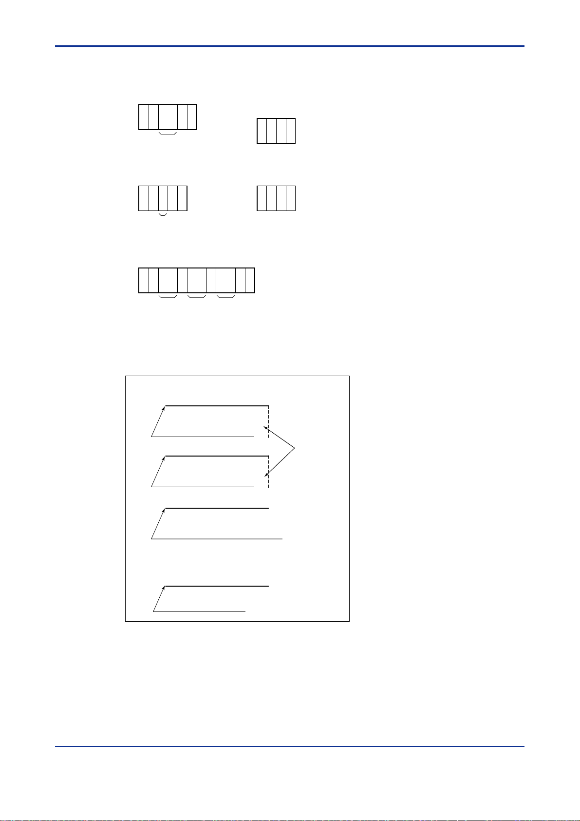
<Toc> <Ind> <5. Actions of External Input and Output Signals >
5.4.2 GC6 T ype Input Data Format
(a) Stream change command (d) Start/stop command
1 23456
SC
a: Stream number
CRL
a
F
¥ Start command
1 234
CRL
BE
F
5-9
(b) Calibration command
1 2345
CRL
CA
a: Standard sample (STD1=1, STD2=2)
F
a
¥ Stop command
1 234
CRL
FI
F
(c) Range change command
1 2345678 9 10 11 12
RA
a b c
a: Stream number
b: Component number
c: Component list number
CRL
F
F0508.EPS
Non-protocol output signal transmission timing
● Send Data (SD)
Analysis data
Analysis completion point
Calibration factor
+9V
+9V
(Transmission
completion)
During calibration
Error alarm
When an alarm occurs (after transmission
completion if the component concentration
value or calibration factor is being transmitted)
● Request to Send (RS)
● Terminal Equipment Ready (ER)
(Always ON)
Processor power ON
+9V
+9V
F0509.EPS
IM 11B03A03-01E 3rd Edition : Aug. 23. 2006-00
Page 67

<T oc> <Ind> <5. Actions of External Input and Output Signals >
I/O instruction format and communication control procedure for handshaking
5-10
I/O instruction format
E: Data receiving
request
F: Data transmission
completion
Output instruction Input instruction
T: Input command
prompt
B: Answerback
(command executed)
W: Answerback
(command not
executed)
If the command is
in an incorrect
format, answerback
is in the format
shown at right.)
A: Data transmission
request
R: Data
retransmission
request
CRL
#E
CRL
#F
CRL
#T
CRL
#B
C
#W
RLF
##W
CRL
#A
CRL
#R
● Normal communication
F
F
F
F
F
F
Supervisory computer
GCCU
● Retransmission
Supervisory computer
GCCU
● Input command
Supervisory computer
GCCU
●
Error handling
Supervisory computer
GCCU
Communication control procedure
A AA
E
Output upon analysis completion or occurrence of an error alarm
(after transmission completion if the component concentration value or
calibration factor is being transmitted)
A RR
E Data 1
Note: If retransmission is requested, data can be transmitted any number of times. If the
total communication time exceeds one analysis cycle, the data is changed into
new data. (The limiter should be considered for the supervisory computer side.)
Command
1
5 seconds
T B or W B or W
Output after
completion of
data transmission
or every 8 to 10
sec periodically
Note: If the sequence has stopped, input commands can be received
continuously until the start signal is received.
(No response from the computer)
E E
3
seconds3seconds
Re-prompted if there is no
command. If there is no command
upon re-prompting, it is assumed
that there is no command.
E
Data 1 Data 1
Command
2
E
Up to 6 commands including those
not executed
FData 1 Data n
5 seconds
If there is no
command during
this period, it is
assumed that
there is no
command.
3.2 seconds
(for reference)
E E
(No response from GCCU)
The same
command is
repeated.
F0510.EPS
IM 11B03A03-01E 3rd Edition : Aug. 23. 2006-00
Page 68

<Toc> <Ind> <5. Actions of External Input and Output Signals >
5-11
5.4.3 GC8/GC1000 T ype Output Data Format (Fixed to 45 Characters)
(1)Analysis value data (concentation)
1 2345678 9 10 11 12 13 14 15 16 17 18 19 20 21 22 23 24 25 26 27 28 29 30 31 32 33 34 35 36 37 38 39 40 41 42 43 44 45
DS
a: Stream number (01 to 24) b: Component number (01 to 24) c: Concentration (without zero suppression) d: Unit
e: Concentration error alarm (Upper limit = A:CHL, Lower limit = A:CLL) f: Retention time (seconds) g: Retention time error alarm
h: Analyzer number 1 to 9
(Note: The error alarm is output only if an error occurs. (Dummy space if no error occurs)
,,
bacd e fgh
PPM A: CHL
%
,,,
A: CLL
T
A: RT
CR: Carriage return,
LF: Line feed
(2)Analysis value data (component ratio operation, linear polynormial operation)
1 2345678 9 10 11 12 13 14 15 16 17 18 19 20 21 22 23 24 25 26 27 28 29 30 31 32 33 34 35 36 37 38 39 40 41 42 43 44434241 45
DS1
2,,
b eac
a: Stream number (01 to 24) b: Component number (01 to 24) c: Operation value (without zero suppression) d: Unit e:Analyzer number 1 to 9
PPM
%
d
Dummy space
C
L
R
F
F0511.EPS
CRL
F0512.EPS
F
(3)Calibration factor
1 234567 8 9 10 11 12 13 14 15 16 17 18 19 20 21 22 23 24 25 26 27 28 29 30 31 32 33 34 35 36 37 38 39 40 41 42 43 44434241 45
CC
a:
d:
,,
b eacd
Standard sample (STD1=1, STD2=2, STD3=3)
Sensitivity error (if an error occurs)
COE
,
b:
Component number (01 to 24)
e:
Analyzer number 1 to 9
Dummy space
c:
Calibration factor (without zero suppression)
(4)Error alarm
• Memory pattern check error • Watchdog timer
• Calibration out of range • Detector 1 (or 2) calibration error
• Isothermal oven temperature error • Power off
• Pressure switch 1 (or 2) OFF • External contact inputs 1 to 8
• Communication error • FID1 (or 2) extinguished
• Calibration repeatability error
1 2345678 9 10 11 12 13 14 15 16 17 18 19 20 21 22 23 24 25 26 27 28 29 30 31 32 33 34 35 36 37 38 39 40 41 42 43 44434241 45
AS /:
a: Month, b: Day, c: Hour, d: Minute e: Error alarm types
f: Analyzer No.1 to 9
,,
bacde f
Note: For 3 characters, the 18th character is a dummy space.
MEM: Memory pattern check error
WDT: Watchdog timer
AD1: Detector 1 calibration error
AD2: Detector 2 calibration error
TMPH: Isothermal oven temperature error
CAR1: Pressure switch 1 OFF
CAR2: Pressure switch 2 OFF
Dummy space
EXT1: External contact input 1
EXT2: External contact input 2
EXT8: External contact input 8
FLM1: FID1 extinguished
FLM2: FID2 extinguished
RPT: Calibration repeatability error
CAL: Calibration out of range
POF: Power off
NSD: Communication error
CRL
F0513.EPS
CRL
F
8 items in total
(GC1000 - GCCU)
F0514.EPS
F
IM 11B03A03-01E 3rd Edition : Aug. 23. 2006-00
Page 69

<T oc> <Ind> <5. Actions of External Input and Output Signals >
5.4.4 GC8/GC1000 T ype Input Data Format
5-12
(a) Stream change command
1 2345678
SM
aab
1 2345678910
SM
CRL
b
F
CRL
F
a: Stream number
b: Analyzer number (1 to 6) or (001 to 255)
(c) Range change command
1 2345678 9 10 11 12
RM
a b c
1 2345678 9 10 11 12
RE
a b c
a: Stream number
b: Component number
c: Component list number
d: Analyzer number (1 to 6) or (001 to 255)
(b) Calibration command
1 234567
CM
1 23456789
CE
CRL
a b
a b
F
CRL
F
a: Standard sample
(STD1=1, STD2=2, STD3=3)
b: Analyzer number (1 to 6) or (001 to 255)
13 14
CRL
F
d
15 1613 14
CRL
F
d
(d) Start/stop command
¥ Start command
1 2
345
CRL
BM
1 2 3 4 567
BE
F
a
a
a: Analyzer number
(1 to 6) or (001 to 255)
CRL
F
¥ Stop command
1 245
3
CRL
FM
1 2 3 467
FE
F
a
5
CRL
a
a: Analyzer number
(1 to 6) or (001 to 255)
F
F0515.EPS
IM 11B03A03-01E 3rd Edition : Aug. 23. 2006-00
Page 70
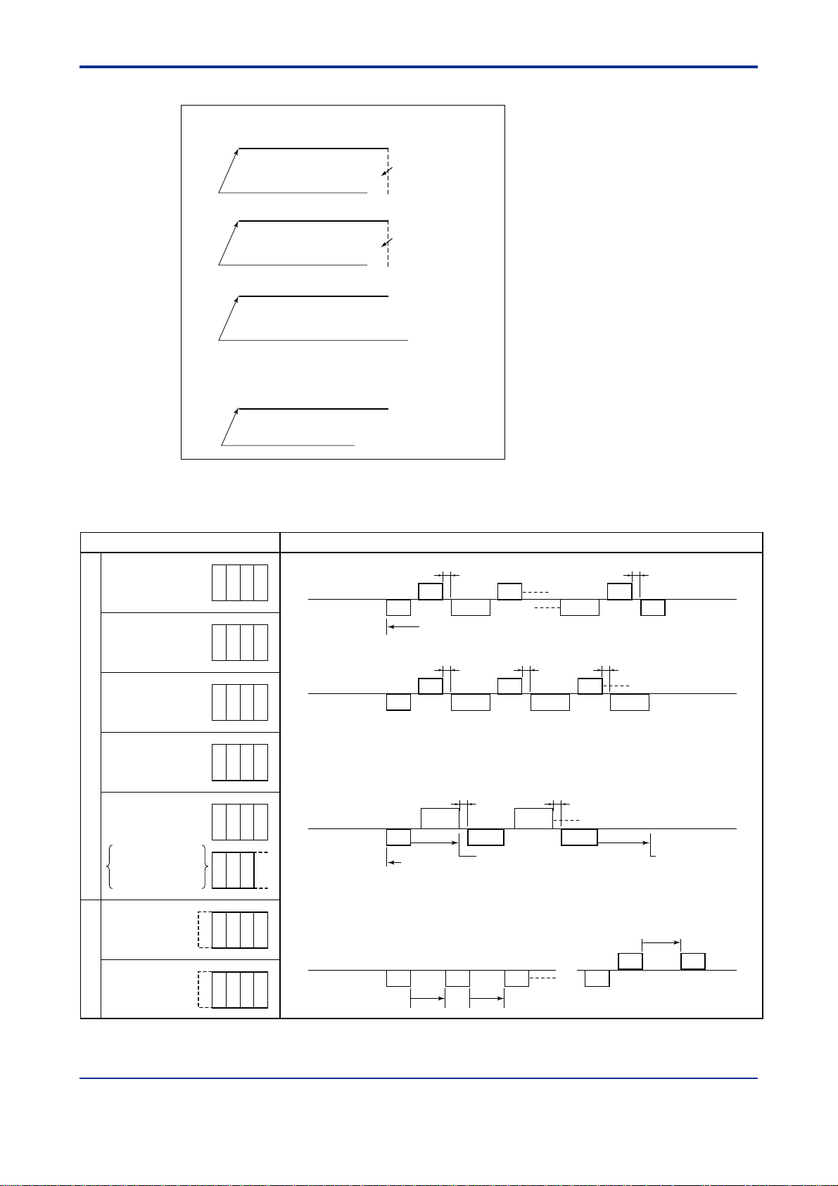
<Toc> <Ind> <5. Actions of External Input and Output Signals >
Non-protocol output signal transmission timing
● Send Data (SD)
Analysis data
AUTO mode analysis
completion point
+9V (RS232C)
(Transmission completion)
5-13
I/O instruction format
E: Data receiving request
F: Data transmission
completion
Output instruction Input instruction
T: Input command prompt
B: Answerback
(command executed)
W: Answerback
(command not executed)
If the command is in
an incorrect format,
answerback is in the
format shown at right.)
A: Data transmission
request
R: Data retransmission
request
Calibration factor
During AUTO mode calibration
Error alarm
When an alarm occurs (after transmission
completion if the component concentration
value or calibration factor is being transmitted)
+9V (RS232C)
(Transmission completion)
+9V (RS232C)
● Request to Send (RS)
● Terminal Equipment Ready (ER)
(Always ON)
Processor power ON
+9V (RS232C)
F0516.EPS
I/O instruction format and communication control procedure for handshaking
Communication control procedure
t (0.4 to 0.5 second)
A AA
Output upon analysis completion or occurrence of an error alarm
(after transmission completion if the component concentration value or calibration
factor is being transmitted)
t
A RR
total communication time exceeds one analysis cycle, the data is changed into
new data. (The limiter should be considered for the supervisory computer side.)
t t
Command
1
5 seconds
Re-prompted if there is no command.
If there is no command upon
re-prompting, it is assumed that there
is no command.
the start signal is received.
(No response from the computer)
E
3
seconds
seconds
E
3
t t
Data 1 Data 1
Command
2
Up to 6 commands including those not executed
CRL
#E
CRL
#F
CRL
#T
CRL
#B
C
#W
RLF
##W
CRL
#A
CRL
#R
● Normal communication
F
F
F
F
F
F
Supervisory computer
GCCU
●
Retransmission
Supervisory computer
GCCU
● Input command
Supervisory computer
GCCU
● Error handling
Supervisory computer
GCCU
E
E Data 1
Note: If retransmission is requested, data can be transmitted any number of times. If the
T B or W B or W
Output after
completion of
data transmission
or every 8 to 10
sec periodically
Note: If the sequence has stopped, input commands can be received continuously until
E E
t
FData 1 Data n
5 seconds
If there is no command
during this period, it is
assumed that there is no
command.
3.2 seconds (for reference)
E E
(No response from GCCU)
The same
command is
repeated.
Note: If #ACRLF or #RCRLF is not received in 20 seconds or more after the data has been sent, the transmission of the
analysis data of that cycle will be aborted.
IM 11B03A03-01E 3rd Edition : Aug. 23. 2006-00
F0517.EPS
Page 71

<T oc> <Ind> <5. Actions of External Input and Output Signals >
5.4.5 MODBUS Communication Data Specification
(1) Coil (Command Contact)
(1) Run command
Commands the start of continuous analysis to the GC1000 Mark II.
(2) Stop command
Commands the stop of continuous analysis to the GC1000 Mark II.
(3) Time setting request
Requests the GC1000 Mark II to set the device clock to values in addresses 40001-
40004. Before this request, time should be set by a holding register.
(4) Stream Sequence setting command
Commands the GC1000 Mark II to perform the specified stream sequence. This
command is rejected if the measurement status is in Calibration/V alidation, including
wait status, or in Stream (1 cycle), including wait status.
(5) Calibration/Validation command
Commands the GC1000 Mark II to perform the specified calibration or validation.
Corresponding numbers to the Calibration/V alidation numbers to be specified are as
follows:
5-14
Calibration 1 to 3: 1 to 3
V alidation 1 to 3: 4 to 6
This command is rejected if the measurement status is in Stream (1 cycle), including
wait status, or the calibration method is set to Automatic/Manual.
(6) Stream (continuous) setting command
Commands the GC1000 Mark II to perform a continuous measurement of the specified stream. This command is rejected if the measurement status is in Calibration/
V alidation, including wait status, or in Stream (1 cycle), including wait status.
Note 1: Coils are automatically reset from 1 to 0 when the slave accepts the message.
Note 2: Pattern requests are queued when received but may not activate immediately.
Note 3: Input relays should be monitored to determine when commands actually activate.
Note 4: When the master sends multiple commands to the slave simultaneously, the slave executes it in the order received
regardless of the content of the commands.
IM 11B03A03-01E
3rd Edition : Aug. 23. 2006-00
Page 72

<Toc> <Ind> <5. Actions of External Input and Output Signals >
(2) Input Relay (Status Contact)
(1) Analyzer normal
The GC1000 Mark II is normal. A 1 is displayed if there is no active level 1 (critical
failure) or level 2 (minor failure) alarm.
(2) Analyzer error
The GC1000 Mark II is faulty . A 1 is displayed if there is at least one active level 1
(critical failure) alarm.
(3) Alarm status change
A 1 is displayed when a new alarm occurs on the GC1000 Mark II. After this status is
read and when at least one alarm status is read, this bit is automatically reset to 0.
(4) Measuring (Run mode)
The GC1000 Mark II is analyzing. A 1 is displayed when it is in Run mode. Otherwise,
0 is displayed.
(5) Stop (Stop mode)
The GC1000 Mark II is not analyzing. A 1 is displayed when it is in Stop mode. Otherwise, 0 is displayed.
(6) Maintenance (other modes)
5-15
If the GC1000 Mark II is in Manual, Lab, or Pause mode, a 1 is displayed. Otherwise,
0 is displayed.
(7) Data update
New analysis data is now available from the GC1000 Mark II. Data update is automatically reset to 0 once data update is read and at least one analysis value is read.
(8) Data valid
Data is valid for a particular peak on the GC1000 Mark II. For analysis peaks, the
analysis value must be between the upper and lower limits and the retention time is at
or below the upper limit. For operation peaks, the data to be used for operation is
valid. A 1 is displayed when data is valid.
(9) Alarm status
The alarm status of the GC1000 Mark II is displayed for each alarm number. If an
alarm occurs, 1 is displayed. Otherwise, 0 is displayed. The alarm number is 1 to 99
for level 1 alarms of the GC1000 Mark II, and 101 to 199 for level 2 alarms of the
GC1000 Mark II.
(10) Calibration factor update
The GC1000 Mark II has new calibration factors for a particular stream. The address
is reset to 0 after the calibration factor update is read and when at least one calibration
factor is read.
(1 1) Executing the Stream Sequence
The corresponding stream sequence on the GC1000 Mark II is being executed.
(12) Measurement status command failure
If the command is not executed after any of the Stream (continuous) setting command, Calibration/V alidation command, Stream Sequence setting command has been
sent by the coil, 1 is displayed. When the command is executed after the next command has been sent, this bit is reset.
IM 11B03A03-01E
3rd Edition : Aug. 23. 2006-00
Page 73

<T oc> <Ind> <5. Actions of External Input and Output Signals >
(3) Holding Register (Set Data)
(1) Time setting value
This is a set of four registers used by the DCS to set the device clock. When the time
setting request coil (address 00003 for GC1000 Mark II and GCIU, 00001 for the
analyzer server) is activated, these entries are used for the year, month/day, hour and
minute/second. Since all devices on the highway synchronize to the analyzer server
clock on a regular basis, the analyzer server clock should be regularly set.
Example : September 25, 1996, 15:23:10
5-16
Year
Month Day
Hour
Minute Second
Figure 5.4 Time Register Configuration
07CC (hexadecimal)
0919 (hexadecimal)
000F (hexadecimal)
170A (hexadecimal)
F0518.EPS
(2) Range setting command
This address allows the range of the component indicated by the specified stream
number and peak number to be changed on the GC1000 Mark II.
(3) Analysis value
These addresses display the same data as the analysis value in the input resister,
however values cannot be written to theses addresses. Only these addresses
support real number (floating point) form.
IM 11B03A03-01E
3rd Edition : Aug. 23. 2006-00
Page 74

<Toc> <Ind> <5. Actions of External Input and Output Signals >
(4) Input Register (Measured Data)
(1) Stream number
The currently active stream number on the GC1000 Mark II is displayed. In Stop or
Manual mode, the stream number is 0. In Lab mode, the stream number is 32.
(2) Starting peak number
The starting peak number assigned to each stream on the GC1000 Mark II is displayed. The maximum number of analysis values, including peaks of all streams, is
255. The number is 0 if no peak is assigned.
(3) Peak number
Peak number assigned to each stream on the GC1000 Mark II is displayed. See the
Figure 5.5 below.
Example: the peak number of Stream 2, Peak 3 is 7.
5-17
Starting peak number = 1
Starting peak number = 5
Starting peak number = 15
Starting peak number = 25
255
Figure 5.5 Example of Peak Allocation
Stream 1
Stream 2
Stream 3
Number of peaks = 4
Number of peaks = 10
Number of peaks = 10
F0519.EPS
(4) Sampling time
This register contains the latest sampling time for each stream on the GC1000 Mark II.
Hour and minutes are stored.
Example : 15:23
Hour Minute
0F17 (hexadecimal)
F0520.EPS
(5) Analysis value
This register contains each analysis value. The value is represented by a fraction to
the full scale or by a real number (floating point format). The full scale is set in advance for each analysis value and the scaling factor is user selectable as either 9999
or 65535. The real number format conforms to the IEEE standard and requires two
registers per peak.
The fraction format is calculated as follows:
(Analysis value x Scaling factor)/Full scale value
For example, if the analysis result is 5 ppm and the range is 0-20 ppm, the value read
using a scaling factor of 9999 is
5
x 9999 = 2499 (09C3)
20
F0521.EPS
For the real number format, units such as % and ppm are considered. For example,
the real number value converted from 1.5 is directly transmitted as 1.5%. The
GC1000 Mark II updates analysis values at the end of each cycle. The GCIU updates
the average values according to the userset scan interval.
(6) Retention time
This register contains the retention time for each measured stream of the GC1000
Mark II. The unit is in seconds.
IM 11B03A03-01E
3rd Edition : Aug. 23. 2006-00
Page 75

<T oc> <Ind> <5. Actions of External Input and Output Signals >
(7) Calibration factor
This register contains the calibration factor for each calibrated stream of the GC1000
Mark II. Since the factors are in the range of 0.000 to 9.999, each value is multiplied
by 1000 and displayed as integers, i.e., 0000 to 9999.
Tab le 5.5 Address Table (GC1000)
Name
Run command
Stop command
Time setting request
Stream sequence select
command
Calibration (validation)
command
Stream (Cont) select
command
Analyzer normal
Analyzer error
Analyzer status change
Address
00001
00002
00003
0001P
0002P
001TT
10001
10002
10003
Recieved the message by the master, the slave reset.
Same as above
Same as above
Same as above P: Stream Sequence number (1 to 4)
Same as above P: 1 to 3 (Cal. 1 to 3), 4 to 6 (Val. 1 to 3)
TT: Stream number (01 to 31)
Reset when the alarm status is read after alarm status change is read.
Description
5-18
Measuring
Stop
Maintenance
Stream
sequence
Stream
(Cont)
Calibration (Validation)
Stream sequence
Data update
Calibration factor update
Data valid
Alarm status
Time setting request
Analysis value
Range select
Stream number
Starting peak number
Peak number
Sampling time
Analysis value
Retention time
Calibration factor
10004
10005
10006
1001P
10021
10022
10023
101TT
102TT
11CCC
12AAA
40001 to 40004
41DDD
4NNQQ
30001
301TT
302TT
303TT
31CCC/-
31DDD
32CCC
33CCC
P: Stream Sequence number (1 to 4)
Reset when the analysis value is read after data update is read. (TT:
Stream number)
Reset when the calibration factor is read after calibration factor
update is read. (TT: Stream number)
CCC: Component number
AAA: Alarm number (001 to 249)
Year (40001), month/day (40002), hour (40003),
minute/second (40004)
Read only (Write disabled)
DDD(real format)5CCC*2-1(CCC: Component number)
NN: Stream number +40, QQ: Peak number
Starting peak number of each stream (TT: Stream number)
Peak number of each stream (TT: Stream number)
Hour/Minute (TT: Stream number)
Analysis value (CCC: component number)
DDD(real format): CCC*2-1(CCC: Peak number)
Seconds
Analysis value (CCC: component number)
T0505.EPS
IM 11B03A03-01E
3rd Edition : Aug. 23. 2006-00
Page 76

<Int> <T oc>
◆ Revision Record
● Manual No. : IM 11B03A03-01E
● Title : GC1000 Mark II Process Gas Chromatograph Overview
Oct. 2001/1st Edition
Newly published
July. 2002/2nd Edition
Introduction modified below;
Added “(5) When touching LCD Panel switches” to “WARNING”;
Corrected a part of “CENELEC (ATEX directive) certification”;
Corrected a part of “Installation site and environment”;
Added “Explanation f or type Y purging” to “WARNING of explosionpr oof enc losure” of FM
and CSA certification;
Corrected title of Sec. 3.3 (2);
Corrected title of Sec. 3.4 (2);
Aug. 2006/3rd Edition
Added the items for EPC and ethernet network (Page 2-2, 3-1, 3-2, 3-4 to 3-11, 4-8, 4-9)
i
IM 11B03A03-01E
3rd Edition : Aug. 23. 2006-00
Page 77

Blank Page
 Loading...