

Page 1

User’s
Manual
FXA120
DAQSTANDARD for FX1000
Hardware Congurator
IM 04L21B01-64EN
3rd Edition
Page 2

Notes
Copyright
Thank you for purchasing DAQSTANDARD for FX1000 (model name: FXA120, hereafter
referred to as DAQSTANDARD). This manual explains how to use DAQSTANDARD
Hardware Configurator. Please read this manual carefully before operating the software
to ensure its correct use.
• The contents of this manual are subject to change without prior notice.
• Every effort has been made in the preparation of this manual to ensure accuracy.
However, if any questions arise or errors are found in this manual, please inform the
nearest Yokogawa sales representative ofce.
• Copying or reproduction by any means of all or any part of the contents of this manual
without permission is strictly prohibited.
• Transfer or loan of the software to a third party is prohibited.
• Once the software is unpacked, Yokogawa will not guarantee the designed operation
of the software, except when the original oppy disk is found to be physically
defective.
• Yokogawa will not accept any responsibility for damage caused directly or indirectly as
result of use of this software.
• The license number cannot be reissued. Therefore, it must be kept in a safe place.
Yokogawa holds the copyright to the software that is on the CD-ROM.
Trademarks
Revisions
• vigilantplant is a registered trademark of Yokogawa Electric Corporation.
• Microsoft and Windows are registered trademarks or trademarks of Microsoft
Corporation in the United States and/or other countries.
• Adobe and Acrobat are registered trademarks or trademarks of Adobe Systems
Incorporated.
• Company and product names that appear in this manual are registered trademarks or
trademarks of their respective holders.
• The company and product names used in this manual are not accompanied by the
registered trademark or trademark symbols (® and ™).
1st Edition: November 2011
2nd Edition: September 2012
3rd Edition: January 2013
3rd Edition : January 2013 (YK)
All Rights Reserved, Copyright © 2011 Yokogawa Electric Corporation
IM 04L21B01-64EN
i
Page 3

Software License Agreement
IMPORTANT - PLEASE READ CAREFULLY BEFORE INSTALLING OR USING:
THANK YOU VERY MUCH FOR SELECTING SOFTWARE OF YOKOGAWA ELECTRIC CORPORATION (“YOKOGAWA”). BY INSTALLING OR OTHERWISE USING THE
SOFTWARE PRODUCT, YOU AGREE TO BE BOUND BY THE TERMS AND CONDITIONS OF THIS AGREEMENT. IF YOU DO NOT AGREE, DO NOT INSTALL NOR USE
THE SOFTWARE PRODUCT AND PROMPTLY RETURN IT TO THE PLACE OF PURCHASE FOR A REFUND, IF APPLICABLE.
1. Scope
This Agreement applies to the following software products and associated documentation of Yokogawa (collectively, “Software Product”). Unless otherwise provided by
Yokogawa, this Agreement applies to the updates and upgrades of the Software Product which may be provided by Yokogawa.
Software Product: DAQSTANDARD for FX1000 (model name: FXA120).
2. Grant of License
2.1 Subject to the terms and conditions of this Agreement, Yokogawa hereby grants to you a non-exclusive and non-transferable right to use the Software Product on a
single or, the following specied number of, computer(s) and solely for your internal operation use, in consideration of full payment by you to Yokogawa of the license
fee separately agreed upon.
Granted number of License: 1 (one)
2.2 Unless otherwise agreed or provided by Yokogawa in writing, the following acts are prohibited:
a) to reproduce the Software Product, except for one archival copy for backup purpose, which shall be maintained with due care subject to this Agreement;
b) to sell, lease, distribute, transfer, pledge, sublicense, make available via the network or otherwise convey the Software Product or the license granted herein to any
other person or entity;
c) to use the Software Product on any unauthorized computer via the network;
d) to cause, permit or attempt to dump, disassemble, decompile, reverse-engineer, or otherwise translate or reproduce the Software Product into source code or other
human readable format, or to revise or translate the Software Product into other language and change it to other formats than that in which Yokogawa provided;
e) to cause, permit or attempt to remove any copy protection used or provided in the Software Product; or
f) to remove any copyright notice, trademark notice, logo or other proprietary notices or identication shown in the Software Product.
2.3 Any and all technology, algorithms, know-how and process contained in the Software Product are the property or trade secret of Yokogawa or licensors to Yokogawa.
Ownership of and all the rights in the Software Product shall be retained by Yokogawa or the licensors and none of the rights will be transferred to you hereunder.
2.4 You agree to maintain the aforementioned property and trade secret of Yokogawa or licensors and key codes in strict condence, not to disclose it to any party other
than your employees, ofcers, directors or similar staff who have a legitimate need to know to use the Software Product and agreed in writing to abide by the obligations
hereunder.
2.5 Upon expiration or termination of this Agreement, the Software Product and its copies, including extracts, shall be returned to Yokogawa and any copies retained in your
computer or media shall be deleted irretrievably. If you dispose of media in which the Software Product or its copy is stored, the contents shall be irretrievably deleted.
2.6 The Software Product may contain software which Yokogawa is granted a right to sublicense or distribute by third party suppliers, including afliates of Yokogawa (“Third
Party Software”). If suppliers of the Third Party Software (“Supplier”) provide special terms and conditions for the Third Party Software which differ from this Agreement,
the special terms and conditions separately provided by Yokogawa shall prevail over this Agreement. Some software may be licensed to you directly by Supplier.
2.7 The Software Product may contain open source software (“OSS”), for which the special terms and conditions separately provided by Yokogawa shall take precedence
over this Agreement.
3. Restrictions on Application
3.1 Unless otherwise agreed in writing between you and Yokogawa, the Software Product is not intended, designed, produced or licensed for use in relation to aircraft
operation or control, ship navigation or marine equipment control, or ground facility or device for support of the aforesaid operation or control, or for use in relation
to rail facility, nuclear related facility, radiation-related equipment, or medical equipment or facility, or under any other circumstances which may require high safety
standards.
3.2 If the Software Product is used for the abovementioned purposes, neither Yokogawa nor Supplier assumes liability for any claim or damage arising from the said use
and you shall indemnify and hold Yokogawa, Supplier, their afliates, subcontractors, ofcers, directors, employees and agents harmless from any liability or damage
whatsoever, including any court costs and attorney’s fees, arising out of or related to the said use.
4. Limited Warranty
4.1 The Software Product shall be provided to you on an “as is” basis at the time of delivery and except for physical damage to the recording medium containing the
Software Product, Yokogawa and Supplier shall disclaim all of the warranties whatsoever, express or implied, and all liabilities therefrom. If any physical defect is found
on the recording medium not later than twelve (12) months from delivery, Yokogawa shall replace such defective medium free of charge, provided that the defective
medium shall be returned to the service ofce designated by Yokogawa at your expense within the said twelve (12) months. THIS LIMITED WARRANTY PROVIDED
IN THIS CLAUSE IS IN LIEU OF ALL OTHER WARRANTIES OF ANY KIND WHATSOEVER AND YOKOGAWA HEREBY DISCLAIMS ALL OTHER WARRANTIES
RELATING TO THE SOFTWARE P RODUCT, WHETHER EXPRESSED OR IMPLIED, INCLUDING WITHOUT LIMITATION, ANY IMPLIED WARRANTIES OF
MERCHANTABILITY, FITNESS FOR ANY PARTICULAR PURPOSE, NON-INFRINGEM ENT, QUALITY, FUNCTIONALITY, APPROPRIATENESS, ACCURACY,
RELIABILITY AND RECENCY. IN NO EVENT SHALL YOKOGAWA WARRANT THAT THERE IS NO INCONSISTENCY OR INTERFERENCE BETWEEN THE
SOFTWARE PRODUCT AND OTHER SOFTWARE NOR SHALL BE LIABLE THEREFOR. The warranty provisions of the applicable law are expressly excluded to the
extent permitted.
4.2 At the sole discretion of Yokogawa, Yokogawa may upgrade the Software Product to the new version number (“Upgrade”) and make it available to you at your expense
or free of charge as Yokogawa deems t. In no event shall Yokogawa be obliged to upgrade the Software Product or make the Upgrade available to you.
4.3 Certain maintenance service may be available for some types of Software Product at Yokogawa’s current list price. Scope and terms and conditions of the maintenance
service shall be subject to those separately provided by Yokogawa. Unless otherwise provided in Yokogawa catalogues or General Specications, maintenance services
will be available only for the latest version and the immediately preceding version. In no event will service for the immediately preceding version be available for more
than 5 years after the latest version has been released. In addition, no service will be provided by Yokogawa for the Software Product which has been discontinued for
more than 5 years. Notwithstanding the foregoing, maintenance service may not be available for non-standard Software Product. Further, in no event shall Yokogawa
provide any service for the Software Product which has been modied or changed by any person other than Yokogawa.
ii
IM 04L21B01-64EN
Page 4

Software License Agreement
5. Infringement
5.1 If you are warned or receive a claim by a third party that the Software Product in its original form infringes any third party’s patent (which is issued at the time of delivery
of the Software Product), trade mark, copyright or other intellectual property rights (“Claim”), you shall promptly notify Yokogawa thereof in writing.
5.2 If the infringement is attributable to Yokogawa, Yokogawa will defend you from the Claim at Yokogawa’s expense and indemnify you from the damages nally granted
by the court or otherwise agreed by Yokogawa out of court. The foregoing obligation and indemnity of Yokogawa shall be subject to that i) you promptly notify Yokogawa
of the Claim in writing as provided above, ii) you grant to Yokogawa and its designees the full authority to control the defense and settlement of such Claim and iii) you
give every and all necessary information and assistance to Yokogawa upon Yokogawa’s request.
5.3 If Yokogawa believes that a Claim may be made or threatened, Yokogawa may, at its option and its expense, either a) procure for you the right to continue using the
Software Product, b) replace the Software Product with other software product to prevent infringement, c) modify the Software Product, in whole or in part, so that it
become non-infringing, or d) if Yokogawa believes that a) through c) are not practicable, terminate this Agreement and refund you the paid-up amount of the book value
of the Software Product as depreciated.
5.4 Notwithstanding the foregoing, Yokogawa shall have no obligation nor liability for, and you shall defend and indemnify Yokogawa and its suppliers from, the Claim, if the
infringement is arising from a) modication of the Software Product made by a person other than Yokogawa, b) combination of the Software Product with hardware or
software not furnished by Yokogawa, c) design or instruction provided by or on behalf of you, d) not complying with Yokogawa’s suggestion, or e) any other causes not
attributable to Yokogawa.
5.5 This section states the entire liability of Yokogawa and its suppliers and the sole remedy of you with respect to any claim of infringement of a third party’s intellectual
property rights. Notwithstanding anything to the contrary stated herein, with respect to the claims arising from or related to the Third Party Software or OSS, the special
terms and conditions separately provided for such Third Party Software or OSS shall prevail.
6. Limitation of Liability
6.1 EXCEPT TO THE EXTENT THAT LIABILITY MAY NOT LAWFULLY BE EXCLUDED IN CONTRACT, YOKOGAWA AND SUPPLIERS SHALL NOT BE LIABLE TO ANY
PERSON OR LEGAL ENTITY FOR LOSS OR DAMAGE, WHETHER DIRECT, INDIRECT, SPECIAL, INCIDENTAL, CONSEQUENTIAL OR EXEMPLARY DAMAGES,
OR OTHER SIMILAR DAMAGES OF ANY KIND, INCLUDING WITHOUT LIMITATION, DAMAGES FOR LOSS OF BUSINESS PROFITS, BUSINESS INTERRUPTION,
LOSS OR DESTRUCTION OF DATA, LOSS OF AVAILABILITY AND THE LIKE, ARISING OUT OF THE USE OR INABILITY TO USE OF THE SOFTWARE PRODUCT,
OR ARISING OUT OF ITS GENERATED APPLICATIONS OR DATA, EVEN IF ADVISED OF THE POSSIBILITY OF SUCH DAMAGES, WHETHER BASED IN
WARRANTY (EXPRESS OR IMPLIED), CONTRACT, STRICT LIABILITY, TORT (INCLUDING NEGLIGENCE), OR ANY OTHER LEGAL OR EQUITABLE GROUNDS.
IN NO EVENT YOKOGAWA AND SUPPLIER’S AGGREGATE LIABILITY FOR ANY CAUSE OF ACTION WHATSOEVER (INCLUDING LIABILITY UNDER CLAUSE
5) SHALL EXCEED THE DEPRECIATED VALUE OF THE LICENSE FEE PAID TO YOKOGAWA FOR THE USE OF THE CONCERNED PART OF THE SOFTWARE
PRODUCT. If the Software Product delivered by Yokogawa is altered, modied or combined with other software or is otherwise made different from Yokogawa
catalogues, General Specications, basic specications, functional specications or manuals without Yokogawa’s prior written consent, Yokogawa shall be exempted
from its obligations and liabilities under this Agreement or law.
6.2 Any claim against Yokogawa based on any cause of action under or in relation to this Agreement must be given in writing to Yokogawa within three (3) months after the
cause of action accrues.
7. Export Control
You agree not to export or provide to any other countries, whether directly or indirectly, the Software Product, in whole or in part, without prior written consent of Yokogawa.
If Yokogawa agrees such exportation or provision, you shall comply with the export control and related laws, regulations and orders of Japan, the United States of America,
and any other applicable countries and obtain export/import permit and take all necessary procedures under your own responsibility and at your own expense.
8. Audit; Withholding
8.1 Yokogawa shall have the right to access and audit your facilities and any of your records, including data stored on computers, in relation to the use of the Software
Product as may be reasonably necessary in Yokogawa’s opinion to verify that the requirements of this Agreement are being met.
8.2 Even after license being granted under this Agreement, should there be any change in circumstances or environment of use which was not foreseen at the time of
delivery and, in Yokogawa’s reasonable opinion, is not appropriate for using the Software Product, or if Yokogawa otherwise reasonably believes it is too inappropriate
for you to continue using the Software Product, Yokogawa may suspend or withhold the license provided hereunder.
9. Assignment
If you transfer or assign the Software Product to a third party, you shall expressly present this Agreement to the assignee to ensure that the assignee comply with this
Agreement, transfer all copies and whole part of the Software Product to the assignee and shall delete any and all copy of the Software Product in your possession
irretrievably. This Agreement shall inure to the benet of and shall be binding on the assignees and successors of the parties.
10. Termination
Yokogawa shall have the right to terminate this Agreement with immediate effect upon notice to you, if you breach any of the terms and conditions hereof. Upon termination of
this Agreement, you shall promptly cease using the Software Product and, in accordance with sub-clause 2.5, return or irretrievably delete all copies of the Software Product,
certifying the same in writing. In this case the license fee paid by you for the Software Product shall not be refunded. Clauses 2.4 and 2.5, 3, 5, 6 and 11 shall survive any
termination of this Agreement.
11. Governing Law; Disputes
This Agreement shall be governed by and construed in accordance with the laws of Japan.
Any dispute, controversies, or differences which may arise between the parties hereto, out of, in relation to or in connection with this Agreement (“Dispute”) shall be resolved
amicably through negotiation between the parties based on mutual trust. Should the parties fail to settle the Dispute within ninety (90) days after the notice is given from either
party to the other, the Dispute shall be addressed in the following manner:
(i) If you are a Japanese individual or entity, the Dispute shall be brought exclusively in the Tokyo District Court (The Main Court) in Japan.
(ii) If you are not a Japanese individual or entity, the Dispute shall be nally settled by arbitration in Tokyo, Japan in accordance with the Commercial Arbitration Rules
of the Japan Commercial Arbitration Association. All proceedings in arbitration shall be conducted in the English language, unless otherwise agreed. The award of arbitration
shall be nal and binding upon both parties, however, each party may make an application to any court having jurisdiction for judgment to be entered on the award and/or for
enforcement of the award.
12. Miscellaneous
12.1 This Agreement supersedes all prior oral and written understandings, representations and discussions between the parties concerning the subject matter hereof to the
extent such understandings, representations and discussions should be discrepant or inconsistent with this Agreement.
12.2 If any part of this Agreement is found void or unenforceable, it shall not affect the validity of the balance of the Agreement, which shall remain valid and enforceable
according to its terms and conditions. The parties hereby agree to attempt to substitute for such invalid or unenforceable provision a valid or enforceable provision that
achieves to the greatest extent possible the economic, legal and commercial objectives of the invalid or unenforceable provision.
12.3 Failure by either party to insist on performance of this Agreement or to exercise a right when entitled does not prevent such party from doing so at a later time, either in
relation to that default or any subsequent one.
End of document
IM 04L21B01-64EN
iii
Page 5

How to Use This Manual
Structure of the Manual
This manual consists of the following three chapters and index.
Chapter Title Content
1 Before using the DAQSTANDARD Explains the PC system environment required for
2 Configuring the FX1000 Explains how to configure the FX1000
3 Troubleshooting Gives a list of error messages and corrective
Index Gives a list of important terms used in this
Scope of this Manual
This manual does not explain the basic operations of your PC’s operating system (OS).
For such descriptions, refer to the Windows User’s Guide etc.
Conventions Used in This Manual
• Unit
K ....................Indicates “1024”. (Example: 100 KB)
use of the DAQSTANDARD. Also explains how to
install it.
measurement conditions and other settings.
measures.
manual.
• Menus, commands, dialog boxes and buttons
Enclosed in [ ].
• Note
Provides useful information regarding operation of the software.
About Images
The images that appear in this manual may be different from those that appear on the
software, but not to a degree that interferes with procedural explanations.
Products Covered in This Manual
Item Described in This Manual
FX1000 Up to firmware version R1.1x.
DAQSTANDARD for FX1000
Hardware Configurator
Revision History
Edition Additions and Changes
1 New edition
2 Revised for upgrade to 9.02 Release: (Added) Italian, Spanish, Portuguese, Russian,
and Korean as display language.
Improvements to descriptions.
3 Revised for upgrade to 9.03 Release: (Added) Pseudo log and nonlinear log settings
of the FX1000 (firmware version R1.11 or later.)
Improvements to descriptions.
In the explanations in this manual, this is referred to as the “FX.”
Up to version R9.03.xx.
iv
IM 04L21B01-64EN
Page 6

Contents
1
Software License Agreement ............................................................................................................ii
How to Use This Manual ..................................................................................................................iv
Chapter 1 Before using DAQSTANDARD
1.1 Overview of DAQSTANDARD.............................................................................................. 1-1
DAQSTANDARD Software Package ................................................................................... 1-1
About Hardware Congurator .............................................................................................. 1-1
1.2 PC System Requirements ................................................................................................... 1-2
Operating System (OS) ....................................................................................................... 1-2
1.3 Starting/Exiting the Software ............................................................................................... 1-3
1.4 Menu Bar and ToolBar ......................................................................................................... 1-4
Menu Bar ............................................................................................................................. 1-4
Toolbar ................................................................................................................................. 1-5
1.5 Displaying the Version Information ...................................................................................... 1-6
Procedure ............................................................................................................................ 1-6
Chapter 2 Configuring the FX1000
2.1 Displaying Setup Data ......................................................................................................... 2-1
Loading Setup Data from the FX ......................................................................................... 2-1
Creating Setup Data by Conguring a New System ............................................................ 2-2
Loading Existing Setup Data ............................................................................................... 2-3
2.2 Setting and Checking the System Configuration and Initializing Setup Data ...................... 2-4
Changing/Checking the System Conguration .................................................................... 2-4
Initializing the Setup Data .................................................................................................... 2-4
2.3 Setting the Measurement Channels .................................................................................... 2-5
Input Type (Mode and Range/Type) .................................................................................... 2-6
Linear Scaling (SCALE) ....................................................................................................... 2-7
Difference Computation (DELTA) ......................................................................................... 2-7
Ref. CH ................................................................................................................................ 2-7
Square Root ......................................................................................................................... 2-7
Unit ...................................................................................................................................... 2-7
Log Scale (LogType1 and LogType2) .................................................................................. 2-8
Low-cut (Can be set when the mode is 1-5V and when the mode is VOLT with square root
(SQRT) selected. ) ............................................................................................................... 2-8
Low-cut value (Can be set when the mode is VOLT with square root (SQRT) selected.) ... 2-8
Calibration Correction .......................................................................................................... 2-9
Alarm ................................................................................................................................. 2-10
Alarm delay ........................................................................................................................ 2-10
Moving Average ..................................................................................................................2-11
Tag ......................................................................................................................................2-11
Memory Sampling ...............................................................................................................2-11
Zone (Zone L and U) ...........................................................................................................2-11
Graph ..................................................................................................................................2-11
Partial (Partial Expanded Display) ..................................................................................... 2-12
Color (Display Color) ......................................................................................................... 2-12
Green Band ....................................................................................................................... 2-12
Alarm Mark ........................................................................................................................ 2-13
Copying and Pasting Setup Data ....................................................................................... 2-13
Setting One Channel at a Time .......................................................................................... 2-14
2
3
8
Index
IM 04L21B01-64EN
v
Page 7

Contents
2.4 Setting the Computation Channels .................................................................................... 2-15
Turning Computation ON/OFF ........................................................................................... 2-15
Entering Expressions ......................................................................................................... 2-15
Span (Display Span) and Point .......................................................................................... 2-16
Unit .................................................................................................................................... 2-16
TLOG (TLOG Computation) .............................................................................................. 2-16
Alarm and Tag .................................................................................................................... 2-16
Rolling Average .................................................................................................................. 2-16
Memory Sampling, Zone, Graph, Partial, Color, Green Band, and Alarm Mark ................ 2-16
Constant ............................................................................................................................ 2-16
Copying and Pasting Setup Data ....................................................................................... 2-17
Setting One Computation Channel (Math Channel) at a Time .......................................... 2-17
2.5 Entering General Settings .................................................................................................. 2-18
Daylight Saving Time ......................................................................................................... 2-18
Group ................................................................................................................................. 2-19
Display ............................................................................................................................... 2-21
Message ............................................................................................................................ 2-24
Timer .................................................................................................................................. 2-25
Event Action ....................................................................................................................... 2-27
File ..................................................................................................................................... 2-29
Event Data ......................................................................................................................... 2-30
Custom Menu .................................................................................................................... 2-31
Aux ..................................................................................................................................... 2-32
2.6 Entering Basic Settings ...................................................................................................... 2-33
Environment ....................................................................................................................... 2-33
Alarm ................................................................................................................................. 2-38
Scan Interval ...................................................................................................................... 2-40
Measure Function .............................................................................................................. 2-41
Report ................................................................................................................................ 2-42
Key Lock ............................................................................................................................ 2-44
Login .................................................................................................................................. 2-45
Ethernet ............................................................................................................................. 2-47
Serial .................................................................................................................................. 2-61
Aux ..................................................................................................................................... 2-64
2.7 Sending the Setup Data to the FX ..................................................................................... 2-65
Setup Data That Is Sent..................................................................................................... 2-65
Sending Address Setup Data ............................................................................................. 2-65
Sending Setup Data Other Than the Address Setup Data ................................................ 2-66
2.8 Saving the Setup Data ....................................................................................................... 2-67
2.9 Printing Setup Data ............................................................................................................ 2-68
Print Format Settings ......................................................................................................... 2-68
Print Example (Table) ........................................................................................................ 2-69
Print Example (Text) .......................................................................................................... 2-71
Print Setup ......................................................................................................................... 2-72
Print Preview ...................................................................................................................... 2-72
Printing ............................................................................................................................... 2-72
2.10 Starting and Stopping Measurement on the FX ................................................................. 2-73
2.11 Viewing the FX Information ................................................................................................ 2-74
2.12 Characters That Can Be Used ........................................................................................... 2-75
Chapter 3 Troubleshooting
3.1 Troubleshooting ................................................................................................................... 3-1
Index
vi
IM 04L21B01-64EN
Page 8

Chapter 1 Before using DAQSTANDARD
1.1 Overview of DAQSTANDARD
DAQSTANDARD Software Package
DAQSTANDARD consists of the following two software applications.
• Viewer
• Hardware Congurator
This manual explains the Hardware Congurator.
• Viewer
Data Viewer displays the values and waveforms of the measured data from the
recorder and prints them.
• Hardware Configurator
Hardware Congurator is a software application for creating setup data for the
recorder. It can send setup les that you have created to the recorder and save them
to storage media.
About Hardware Configurator
Creating Setup Data
You can use one of the following three methods to create setup data:
• Specify a new device and options.
• Edit setup data that is stored on an external storage medium or the PC.
• Edit setup data received from the recorder.
1
Before using DAQSTANDARD
Configuring the Recorder
You can use one of the following two methods to configure the recorder:
• Load the settings to the recorder from a CF card or other external storage medium.
• Send the setup data to the recorder.
Printing Setup Data
You can print setup data.
Recorder Information Acquisition
You can acquire the recorder’s device information through communication.
IM 04L21B01-64EN
1-1
Page 9

1.2 PC System Requirements
Hardware
Personal Computer
A computer which runs on Windows XP, Windows Vista, or Windows 7.
CPU and Main Memory
• When Using Windows XP
Pentium III, 600 MHz or faster Intel x64 or x86 processor; 128 MB or more of memory
• When Using Windows Vista
Pentium 4, 3 GHz or faster Intel x64 or x86 processor; 2 GB or more of memory
• When Using Windows 7
32-bit edition: Intel Pentium 4, 3 GHz or faster x64 or x86 processor; 2 GB or more of
memory
64-bit edition: Intel x64 processor that is equivalent to Intel Pentium 4, 3 GHz or faster;
2 GB or more of memory
Hard Disk
Free space of 100 MB or more (more space may be required, depending on the amount
of data stored).
CD-ROM Drive
One CD-ROM drive.
Mouse
A mouse supported by Windows.
Monitor
A video card that is recommended for the OS and a display that is supported by the OS,
has a resolution of 1024×768 or higher, and that can show 65,536 colors (16-bit, high
color) or more.
Interface Port
When communicating through RS-232, use a COM port (COM1, COM2, COM3, or
COM4) supported by Windows.
When communicating through RS-422/RS-485, connect a converter to an RS-232 port.
To communicate through an Ethernet connection, you need an Ethernet card supported
by Windows. Also, the TCP/IP protocol must be installed.
Printer
A printer supported by Windows is required. An appropriate printer driver is also required.
Operating System (OS)
1-2
OS Version
Windows XP Home Edition SP3
Professional SP3 (excluding x64 Editions)
Windows Vista Home Premium SP2 (excluding 64-bit editions)
Business SP2 (excluding 64-bit editions)
Windows 7 Home Premium, SP1 (32- or 64-bit edition)
Professional, SP1 (32- or 64-bit edition)
Note
• The time zone can be set in [Date/Time] which can be opened from [Control Panel].
• If daylight saving time is used, mark the check box of “Automatically adjust clock for daylight
saving changes.”
• The time zone should not be set using the autoexec.bat file. If “TZ=GTM0” is set in the file,
specify “rem” to disable it.
• Data created in 2038 or later cannot be handled.
• The font “Courier New” needs to be installed on your personal computer.
IM 04L21B01-64EN
Page 10
1.3 Starting/Exiting the Software
Starting
From the Start menu, select [All Programs] - [DAQSTANDARD] - [Hardware
Configurator].
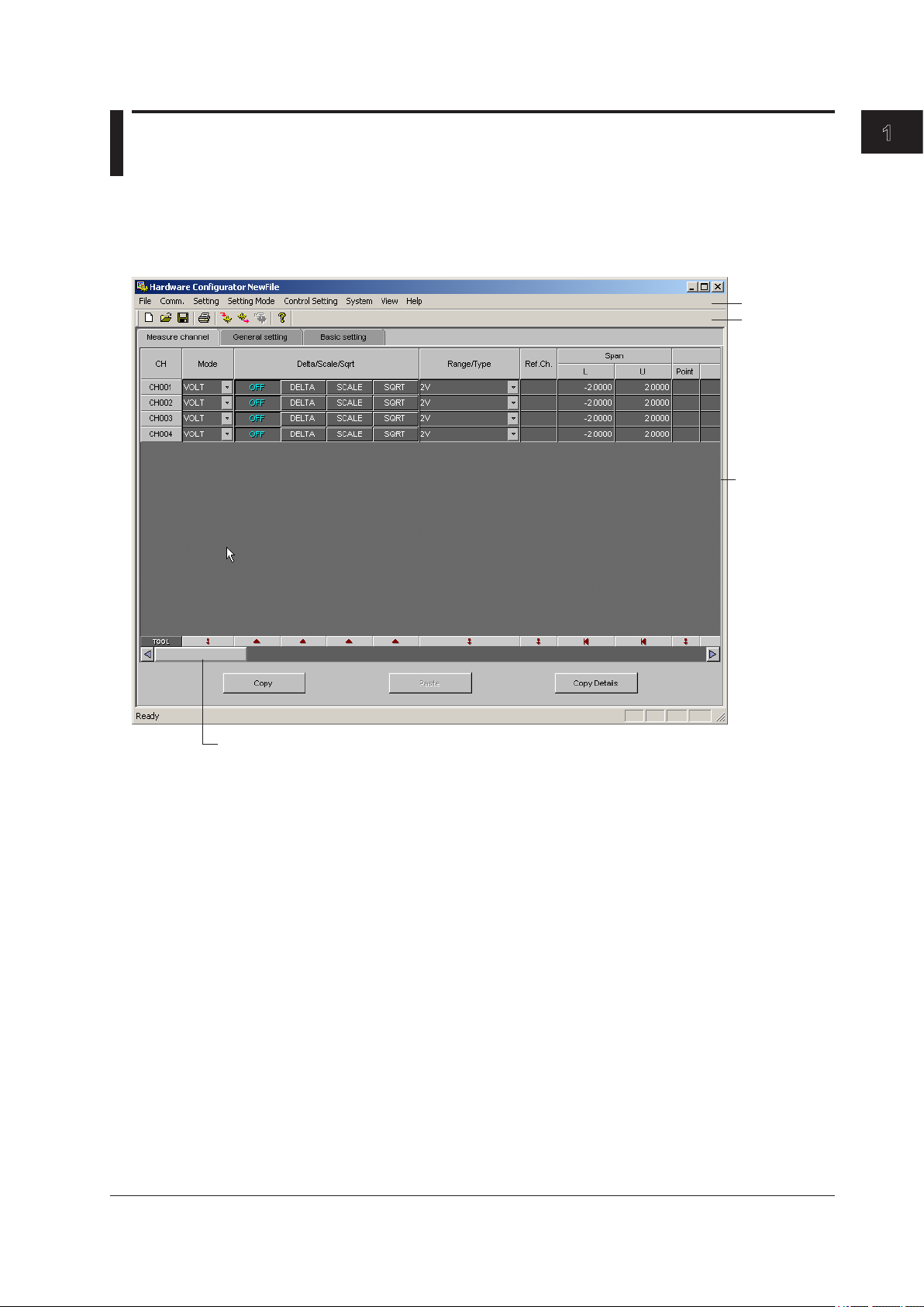
Hardware Configurator starts, and the following window appears.
1
Before using DAQSTANDARD
Menu bar
Toolbar
A vertical scroll
bar may appear.
Exiting
Scroll through the screen (horizontally)
To exit Hardware Configurator, select [File] - [Exit], or click the [X] button.
IM 04L21B01-64EN
1-3
Page 11
1.4 Menu Bar and ToolBar
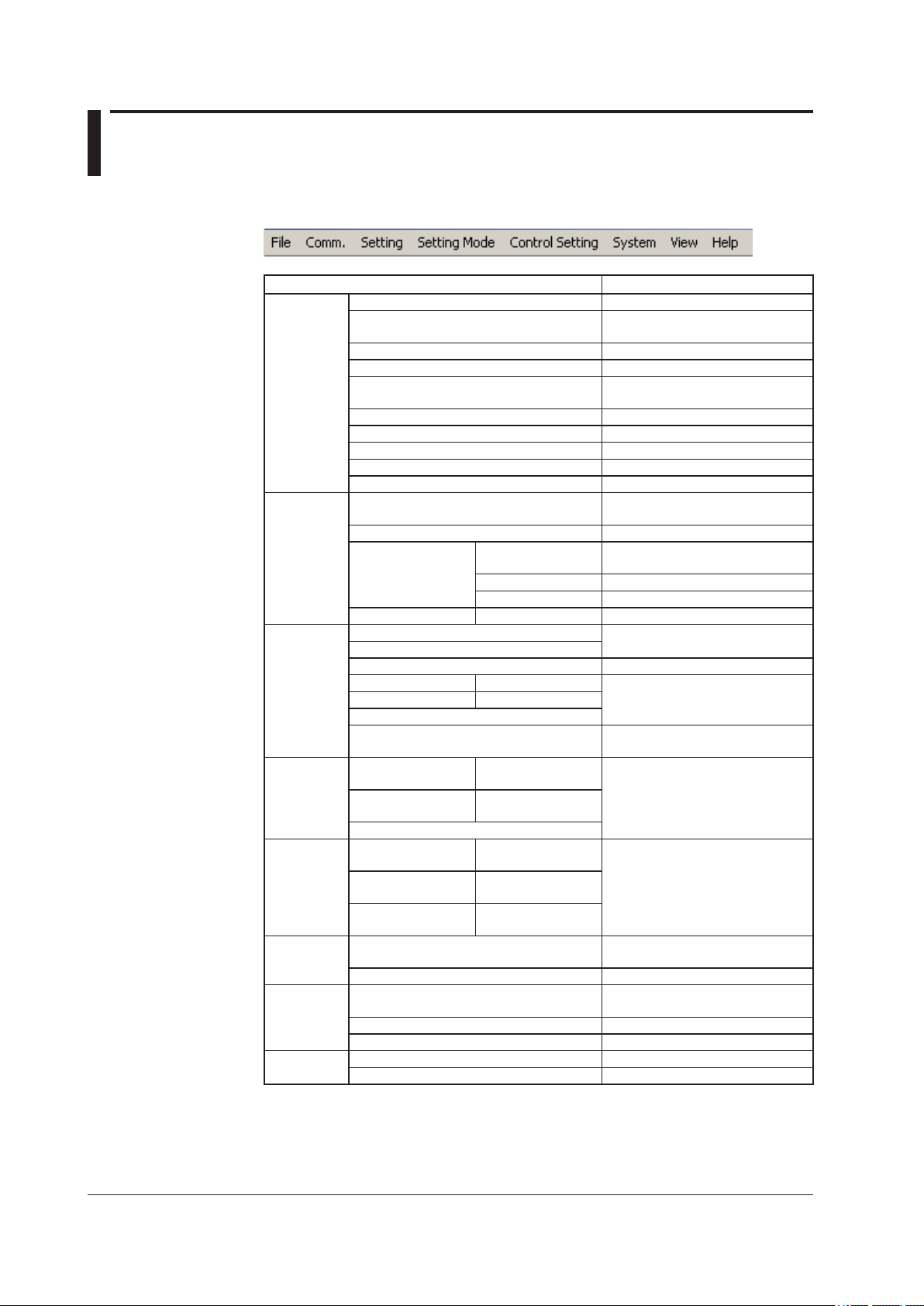
Menu Bar
Only the menu items that can be selected are available.
Menu Description
File New Creates new setup data.
Open Opens setup data that has been
Save Overwrites the current file.
Save As Saves to a specified file name.
Restore Original See the explanation later in this
Print Format Settings See section 1.5.
Print Prints data.
Print Preview Displays a print preview.
Print Setup Set up the printer.
Exit Exits the software.
Comm.* Receive Setting Receives setup data from the
Send Setting Sends setup data to the recorder.
Action Hardware Info Receives the device information
Partial Transfer Address Settings See section 2.7.
Setting Meas Channels This item appears for the FX.
Math Channels
Ext. Channels Not used.
General Setting (Submenu) This item appears for the FX.
Basic Setting (Submenu)
Initialize
Load Changed Settings See the explanation later in this
Setting
Mode
Control
Setting
System System Configuration Set the setup data system
View Standard Toolbar Shows or hides the toolbar.
SET (Regular)
Setting
SETUP (Basic)
Setting
Initialize
SET (Regular)
Setting
SETUP (Basic)
Setting
Program Pattern
Setting
Data Adjustment Not used.
saved in the past.
section.
recorder.
from the recorder and displays it.
Memory&Math Start Starts memory sampling.
Memory&Math Stop Stops memory sampling.
section.
(Submenu) Not used.
(Submenu)
(Submenu) Not used.
(Submenu)
(Submenu)
configuration.
1-4
Status bar Shows or hides the status bar.
Data Adjustment Dialog Not used.
Help About Shows the version. See section 1.6.
User’s Manual Shows the user’s manual.
* This can only be used on FXs that have a communication interface (/C2, /C3, or /C7 option).
IM 04L21B01-64EN
Page 12
1.4 Menu and Tool Bars
About [File] - [Restore Original]
When you select [File] - [Restore Original], the data from the last time one of the following
operations was performed is restored.
• [File] - [New]
• [File] - [Open]
• [File] - [Save]
• [File] - [Save As]
• [Comm.] - [Receive Setting]
• [Comm.] - [Send Setting]
• [Comm.] - [Partial Transfer]
• [System] - [System Configuration]
About [Setting] - [Load Changed Settings]
You can change the settings on the currently displayed setting screen to those of a
specified setup file.
Select [Setting] - [Load Changed Settings].
1.
The [Open] dialog box appears.
Specify a file, and click [Open].
2.
The contents of the displayed setting screen are changed to those of the specified file.
Note
• Only the settings on the displayed setting screen are changed.
• Settings that do not match those of the setup data that you are currently editing are not
loaded.
• Settings that are not included in the setup data that you are currently editing are not loaded.
1
Before using DAQSTANDARD
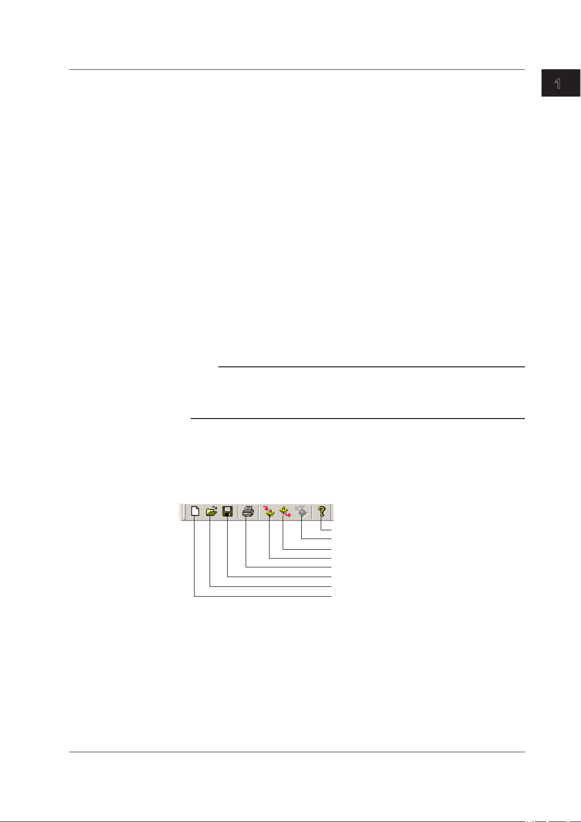
Toolbar
Displaying the Manual
Select [Help] - [User’s Manual]. A PDF of the manual appears.
Only the icons of tools that can be used are available.
Version information
Not used
Send data*
Receive data*
Print
Save
Open
New
* This can only be used on FXs that have a communication interface (/C2, /C3, or /C7 option).
IM 04L21B01-64EN
1-5
Page 13

1.5 Displaying the Version Information
Procedure
Select [Help] - [About] on the menu bar.
1.
The [About] dialog box appears.
Click [OK] to close the [About] dialog box.
2.
1-6
IM 04L21B01-64EN
Page 14
1
Chapter 2 Configuring the FX1000
2.1 Displaying Setup Data
The Hardware Configurator can transmit and receive the setup data, change the setup
data, and create new setup data. The settings on the setting screen vary depending on
the specifications of the connected FX.
The setting screen may differ from your actual screen.
Loading Setup Data from the FX
This procedure can only be performed on FXs that have a communication interface (/C2,
/C3, or /C7 option). Before performing the following procedure, please make sure that the
communication method and parameters are correct.
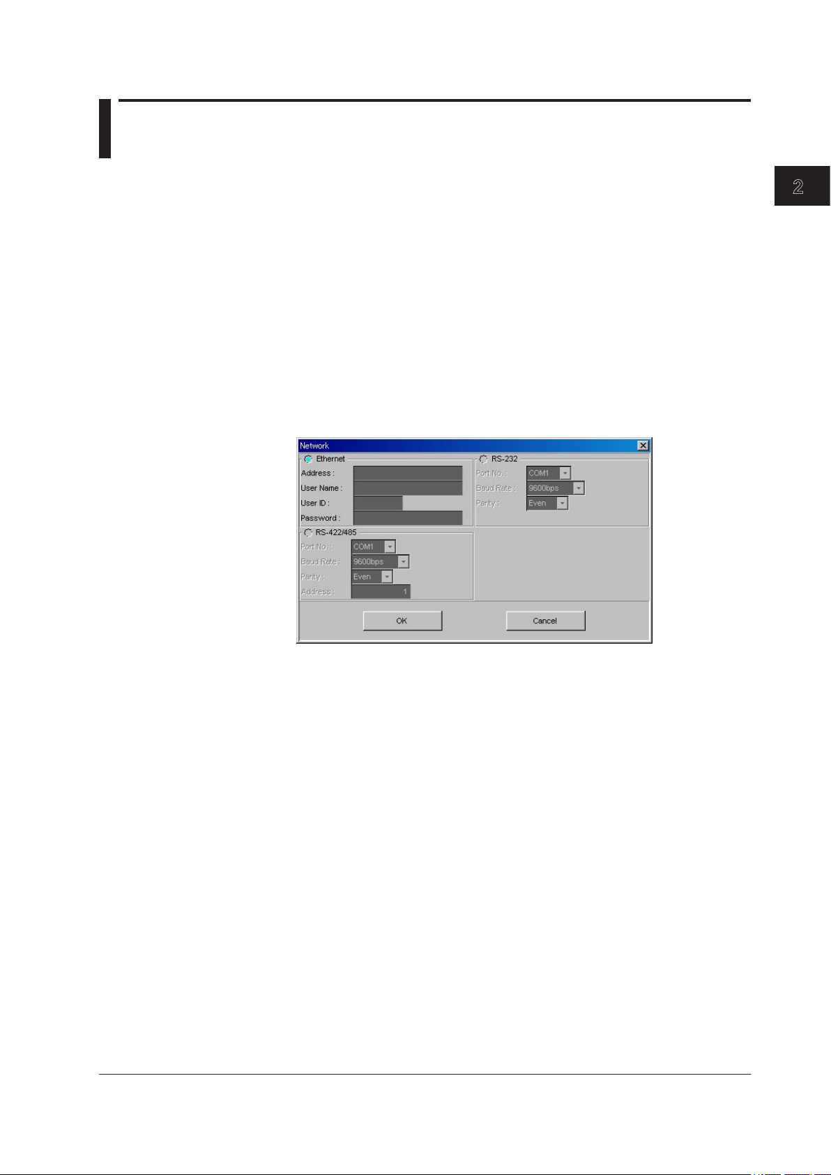
Click the [Receive Data] button, or select [Comm.] - [Receive Setting] from the
1.
menu bar.
The [Network] dialog box appears.
Enter the parameters, and click the [OK] button.
2.
2
Configuring the FX1000
3.
The [Receive Data] dialog box appears.
Click the [OK] button.
The software receives the setup data from the FX and displays it.
IM 04L21B01-64EN
2-1
Page 15
2.1 Displaying Setup Data
Creating Setup Data by Configuring a New System
Click the [New] button, or choose [File] - [New] from the menu bar.
1.
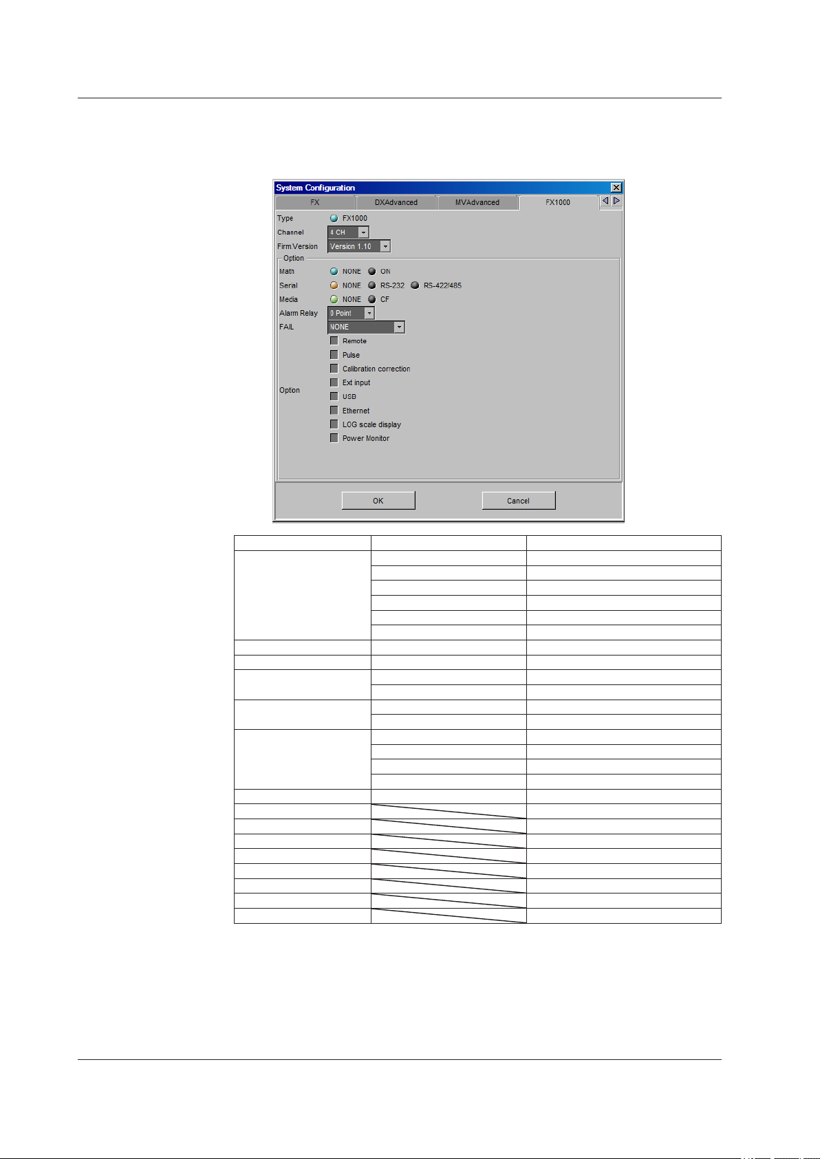
The [System Configuration] dialog box opens. Click the [FX1000] tab.
Item Setting Explanation
Channel 2CH FX1002
4CH FX1004
6CH FX1006
8CH FX1008
10CH FX1010
12CH FX1012
Firm.Version (Version number) FX firmware version
Math ON /M1 option
Serial RS-232 /C2 option
RS-422/485 /C3 option
Media NONE No CF card slot
CF CF card slot present
Alarm Relay 2 Point /A1 option
4 Point /A2 option
6 Point /A3 option
12 Point /A4A option
FAIL FAIL and status output relays /F1 option
Remote /R1 option
Pulse /PM1 option
Calibration correction /CC1 option
Ext input /N3F option
USB /USB1 option
Ethernet /C7 option
LOG scale display /LG1 option
Power Monitor /PWR1 option
* Select the number of the FX1000 firmware. If the firmware version is R1.11, select [Version
1.10] from the list.
Enter all settings on the [FX1000] tab, then click the [OK] button. The FX setting
2.
*
screen in displayed.
2-2
IM 04L21B01-64EN
Page 16

1
Loading Existing Setup Data
Click the [Open] button, or choose [File] - [Open] from the menu bar.
1.
The [Open] dialog box is displayed.
2.1 Displaying Setup Data
Select a setup data file (with the .PDL extension).
2.
2
Configuring the FX1000
IM 04L21B01-64EN
2-3
Page 17
2.2 Setting and Checking the System Configuration and Initializing Setup Data
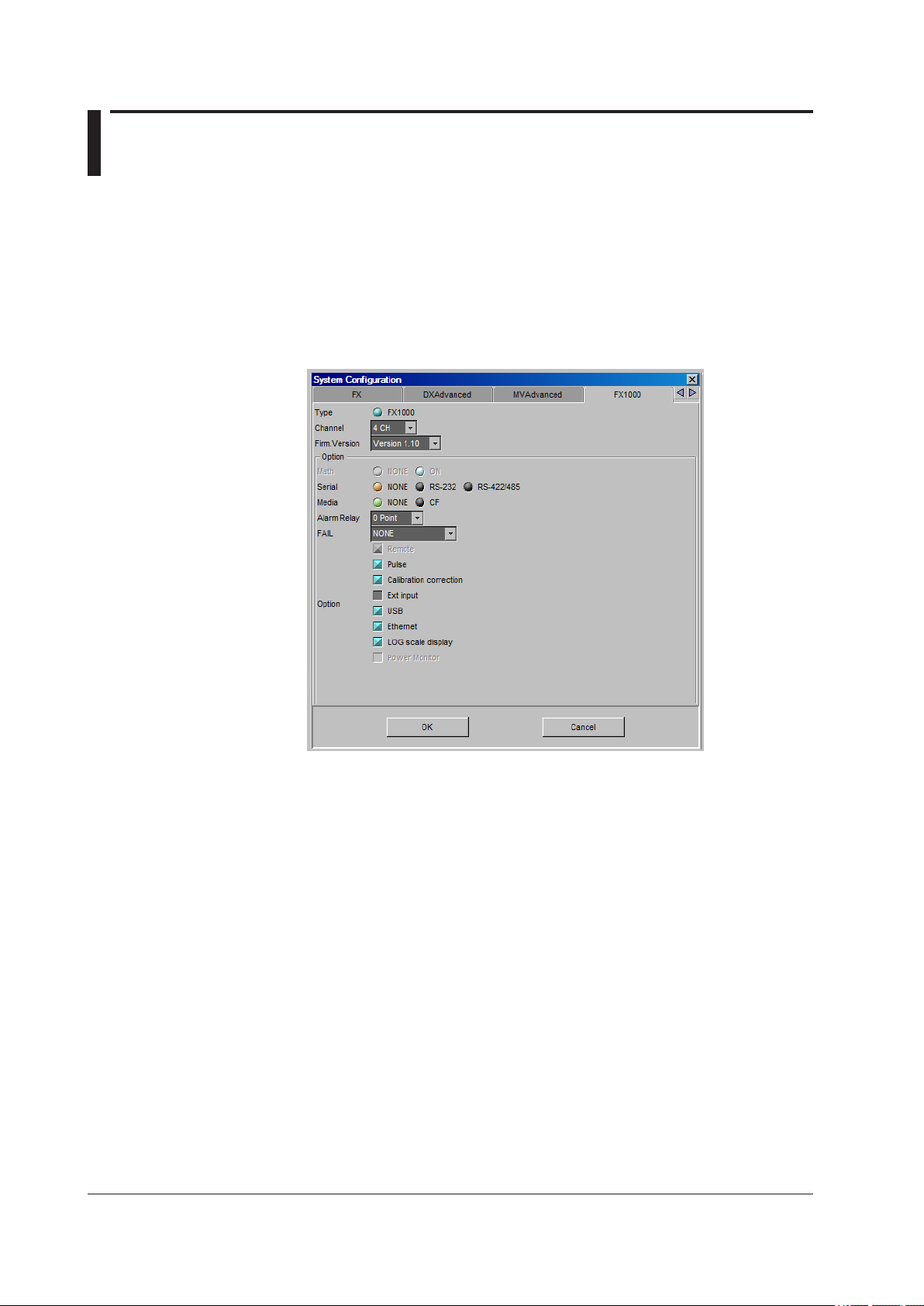
Changing/Checking the System Configuration
You can create new hardware configuration files, or open existing configuration files
and then check the system configuration or change the configuration according to the
specifications of the connected FX.
Normally, a system is set up according to the specifications of the FX to be set up.
Choose [System] - [System Configuration] from the menu bar.
1.
The [System Configuration] dialog box opens.
Click the [FX1000] tab.
2.
3.
4.
Initializing the Setup Data
1.
2.
2-4
Change the various settings according to the FX that you will connect to (Blue,
orange, and green are used to indicate the selected items. Gray is used to
indicate the items that are not selected.).
The settings in the Option group differ depending on the model and options of
the instrument.
For example, if you select [Pulse] (the check box is displayed in blue), you
cannot select [Math] or [Remote].
After changing the configuration and clicking the [OK] button, the message,
“System configuration has been changed. The input configuration and data will be
initialized. Continue?” appears.
Click the [OK] button to initialize the data.
Choose [Setting] - [Initialize] from the menu bar.
The [Initialize] dialog box opens.
Click the [OK] button to initialize the current settings.
The changed settings are restored to the condition when they were newly created.
IM 04L21B01-64EN
Page 18
1
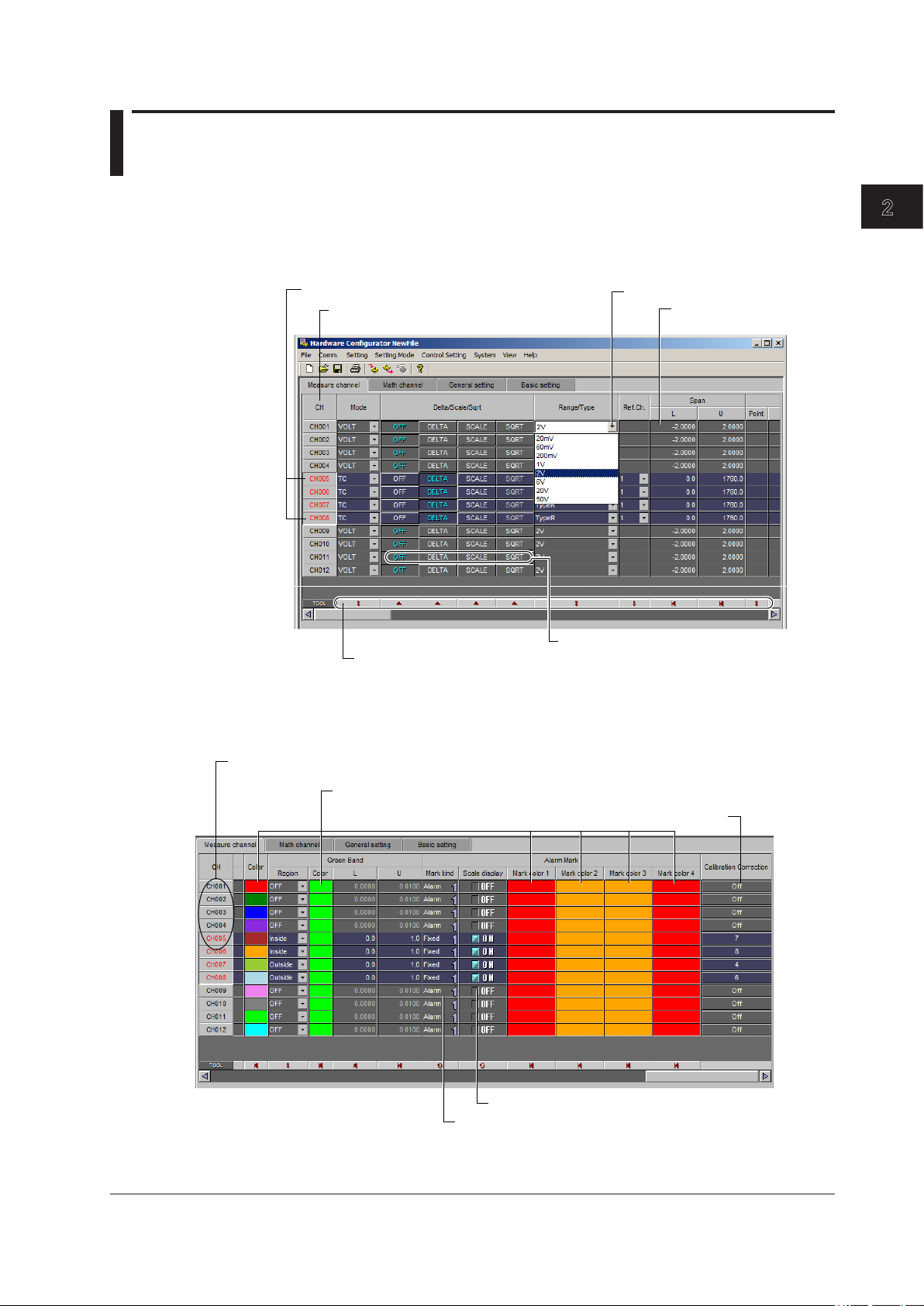
2.3 Setting the Measurement Channels
Drag to select a range of channels.
Double-click the channel number when you want to configure the settings for each channel separately.
The items that you can configure vary depending on the system configuration and the
settings.
Setting Operation
You can select a range of channels and set each item at once.
Click and select from the list
Click to toggle the selection of
all channels ON and OFF.
2
Configuring the FX1000
Click the text box to
enter a number
Click the button to select the function.
Buttons for configuring the selected channels at once
The range select shortcut buttons are effective on the channel range selected. If no
channels are selected, the range select shortcut buttons are effective on all channels.
For the function of each button, see next page.
(A screen for setting the corresponding channel will be displayed.)
Click this to display the color settings screen.
Click this to display the calibration correction setting screen.
Click this to toggle ON and OFF.
Click this to switch the display.
IM 04L21B01-64EN
2-5
Page 19

2.3 Setting the Measurement Channels
Buttons for Configuring the Selected Channels at Once
Copies the settings of the first channel
Set all channels at once.
Turns all channels ON or OFF
Initializes all channels
Set all values to their minimum settable values.
Set all values to their maximum settable values.
Input Type (Mode and Range/Type)
Delta, scaling, and square root are supported for the various modes as shown below.
Mode Delta, Scaling, and Square Root
OFF DELTA SCALE SQRT LogType1 LogType2
SKIP No No No No No No
VOLT Yes Yes Yes Yes Yes Yes
TC Yes Yes Yes No No No
RTD Yes Yes Yes No No No
DI Yes Yes Yes No No No
1-5 V No No Yes No No No
The values in the Range/Type list box vary depending on the above settings.
• Span L, Span U
Input range. You cannot enter values that are outside of the range.
Note
• You cannot set the same value to [Span L] and [Span U].
• When [Delta/Scale/Sqrt/LOG Scale] is set to [Sqrt], [LogType1], or [LogType2], or [Mode] is
set to [1-5V], you can only set [Span L] to a value that is less than [Span U].
2-6
IM 04L21B01-64EN
Page 20

1
Linear Scaling (SCALE)
Converts the unit to obtain the measured value.
• Scale L, Scale U
Input range after converting the unit. The selectable range is from –30000 to 30000.
• Point
Set the number of digits to the right the decimal to four digits or less.
Note
• The FX converts the measured value to a value obtained by removing the decimal point
from the value span specified by [Scale L] and [Scale U]. For example, if the scale setting is
“–5 to 5,” the value is converted to a value within the span of “10”; if the scale setting is “–5.0
to 5.0,” the value is converted to a value within a span of “100.” In this case, the resolution
of the value converted to a span of “10” is lower than the value converted to a span of “100.”
To prevent the display from becoming rough, it is recommended that the scale be set so that
this value is greater than 100.
• You cannot set the same value to [Scale L and [Scale U].
• When the [Mode] is [1-5V] or [Sqrt], [Scale L] must be less than [Scale U].
Difference Computation (DELTA)
Displays the difference between the input and the reference channel.
If difference computation is performed between channels that have different range and
type settings, the decimal position of the computed result is set to that of the channel
computing the difference. If the number of digits to the right of the decimal of the
reference channel is greater than that of the channel computing the difference, the
reference value below the least significant digit of the channel computing difference is
rounded beforehand.
2.3 Setting the Measurement Channels
2
Configuring the FX1000
Ref. CH
Square Root
Unit
The reference channel for difference computation.
Note
If you set the reference channel of a differential computation between channels to a channel
that is set to [LogType1] or [LogType2], an error will be returned as the measured result of the
differential computation between channels.
Computes and displays the square root of the input. This setting can be used only when
the input mode is set to VOLT (voltage). As necessary, set the span, scale, and unit. You
can only configure the settings such that [Scale_L] is less than [Scale_U].
Enter the unit using up to six characters.
IM 04L21B01-64EN
2-7
Page 21

2.3 Setting the Measurement Channels
Log Scale (LogType1 and LogType2)
When you use the log scale (/LG1 option), set the scale upper and lower limits and alarm
values by specifying the mantissas and exponents.
Type Item Setting Conditions
Lower limit
mantissa
Lower limit
LogType1
(lower limit < upper
limit)
LogType2
(lower limit ≠ upper
limit)
exponent
Upper limit
mantissa
Upper limit
exponent
Lower limit
mantissa
Lower limit
exponent
Upper limit
mantissa
Upper limit
exponent
1.00 to 9.99
Integer between –15 and 15
1 ≤ |upper limit – lower limit| ≤ 15
Integer between –15 and 15.
2 ≤ |upper limit – lower limit| ≤ 15
1.00 to 9.99
Integer between –15 and 15
1 ≤ |upper limit – lower limit| ≤ 15
Integer between –15 and 15
2 ≤ |upper limit – lower limit| ≤ 15
1.00 to 9.99
Integer between –15 and 15
1 ≤ |upper limit – lower limit| ≤ 15
Integer between –15 and 14
1 ≤ |upper limit – lower limit| ≤ 14
Cannot be set
Integer between –15 and 15
1 ≤ |upper limit – lower limit| ≤ 15
Integer between –15 and 14
1 ≤ |upper limit – lower limit| ≤ 14
The lower limit mantissa must
be 1.00.
The lower limit mantissa must
be a value other than 1.00.
The lower limit mantissa must
be 1.00.
The lower limit mantissa must
be a value other than 1.00.
The lower limit mantissa must
be 1.00.
The lower limit mantissa must
be a value other than 1.00.
This is the same value as the
lower limit mantissa.
The lower limit mantissa must
be 1.00.
The lower limit mantissa must
be a value other than 1.00.
Low-cut (Can be set when the mode is 1-5V and when the mode is VOLT with square root (SQRT) selected. )
Select [ON] to use the low-cut function.
Low-cut value (Can be set when the mode is VOLT with square root (SQRT) selected.)
Set the low-cut value in the range of 0.0% to 5.0% of the input span.
Measured value
Result of square root computation
Low-cut value
Input value
2-8
IM 04L21B01-64EN
Page 22
1
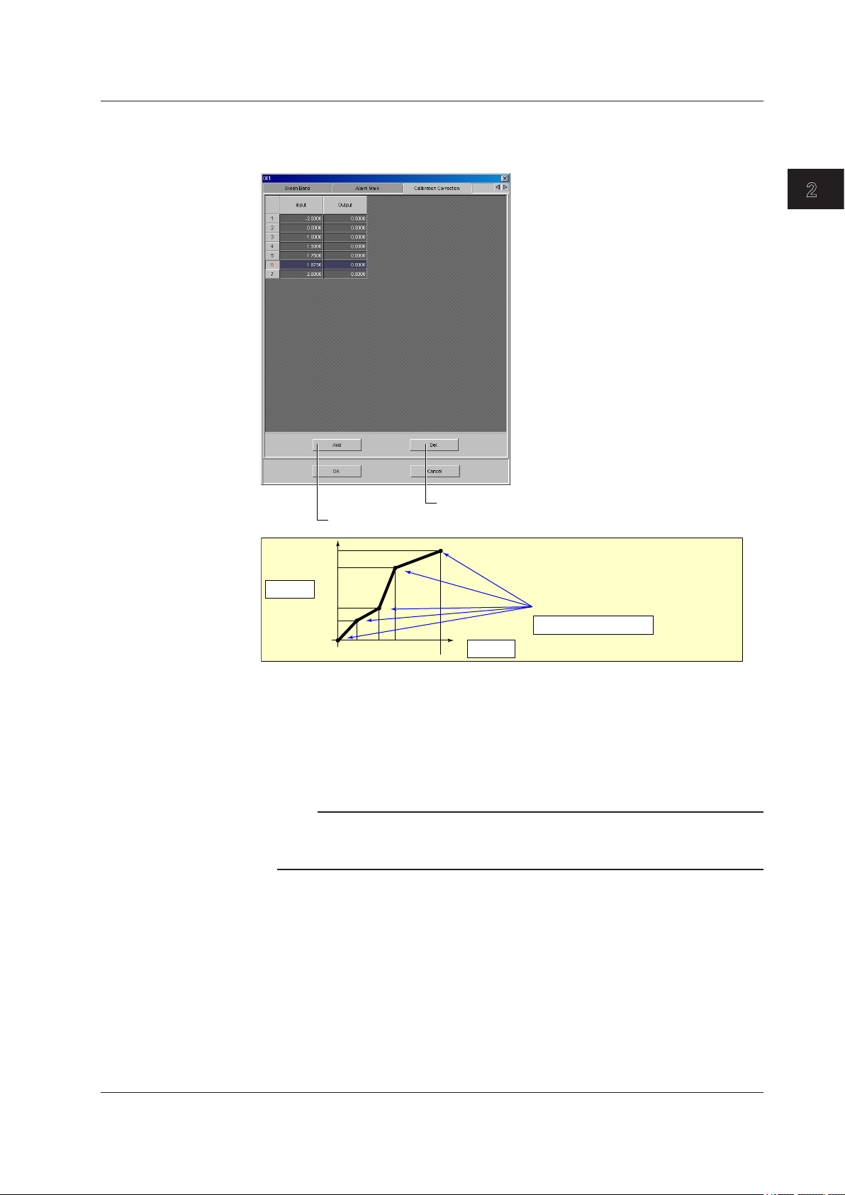
Calibration Correction
Set the input and output values for the calibration correction. The number of set points
(including the start and end points) can be specified in the range 2 to 16.
2.3 Setting the Measurement Channels
2
Configuring the FX1000
Click to delete the selected row.
Click to add set points (rows) to the number of calibration set points.
Condition
X1 < X2 < X3 < X4 < X5
Calibration set points
Number of set points
Output
Y5
Y4
Y3
Y2
Y1
X1 X2 X3 X4 X5
Input
Selectable Range of Input and Output Values
• Channels on which linear scaling is specified (SCALE)
–30000 to 30000 (the decimal place is the same setting as the scale value)
• Other channels (OFF, DELTA, SQRT, LogType1)
Value in the measurable range of the selected range
Example: –2.0000 to 2.0000 for 2 V range
Note
• When you set calibration correction on a channel that is set to LogType1 (nonlinear logs),
the set points are specified in the range of voltage values.
• You cannot set calibration correction on a channel that is set to LogType2.
IM 04L21B01-64EN
2-9
Page 23

2.3 Setting the Measurement Channels
Alarm
Four alarms (Alarm 1 to 4) can be specified on each channel.
Type
Select H, L, h, l, R, r, T or t. The selectable alarms vary depending on the input mode
and computation type. For details, see chapter 3 in the FX User’s Manual.
Alarm value and exponent
Alarm is generated using the specified value as the boundary. The selectable range of
alarm values vary depending on the input mode and range.
For channels that are set to [LogType1] or [LogType2], set the value by specifying the
mantissa and exponent. Enter the mantissa under [Value].
Alarm Relay
Specify the internal switch or output relay that will be used to generate alarms.
Otherwise, select [None].
Detect
This can be selected when [No Logging] is turned [ON] under [Alarm] - [Alarm action] in
the [Basic Setting] tab.
Select whether to show or hide the alarm indication when an alarm occurs. If set to [OFF],
a signal is output to the alarm output relay or internal switch when an alarm occurs, but it
is not indicated on the screen. The alarm is also not recorded in the alarm summary.
Alarm delay
Set the alarm delay time to an integer value from 1 to 3600 s. If the measured value
remains above or below the set alarm value for the set period of time (the delay time),
an alarm is activated.
Note
FX specications
• The alarm delay time takes on a value that is an integer multiple of the scan interval. For
example, if the alarm delay time is set to 5 s when the scan interval is 2 s, the actual delay
time is 6 s.
• The delay alarm has the following special operations.
• If the computation is stopped in a condition in which the computed value is exceeding the
alarm setting when a delay alarm is set on a computation channel, the alarm is turned
On after the specified period (delay period) elapses.
• The alarm detection operation is reset if a power failure occurs. The operation restarts
after the power recovers.
• If the alarm setting of the delay high limit alarm is changed when an alarm is already
activated and the input is greater than or equal to the new setting, the alarm continues.
For all other cases, the alarm detection operation starts at the new setting. This is also
true for the delay lower limit alarm.
2-10
IM 04L21B01-64EN
Page 24

1
Moving Average
2.3 Setting the Measurement Channels
To use the moving average, select the sampling count [Times] (2 to 400).
Tag
You can use the tag instead of the channel number to be displayed on the screen.
This can be selected when [Tag] is [Tag] under [Detail Setting] in the [Basic Setting] tab.
You can enter tags using up to 16 characters.
Memory Sampling
Turn [ON] (sample) or [OFF] (do not sample).
Zone (Zone L and U)
You can select the range of the screen in which the waveform of each channel is to be
displayed.
Specify positions (%) on the display scale for the upper and lower limits.
The conditions for setting the zones are as follows:
• Range: 0% to 100%
The lower limit L must be less than the upper limit
• The difference between the lower and upper limits is at least 5%.
Graph
For details, see section 5.7 in the FX User’s Manual.
Scale display position
Select the scale display position on the trend display from 1 to 6. Select [OFF] if you do
not wish to display the scale.
Scale divide position
Select the number of main scale marks on the trend display from 4 to 12 and C10.
If you select [C10], the scale is equally divided into 10 sections by main scale marks, and
scale values are indicated at 0, 30, 50, 70, and 100% positions.
This setting is not applied to any channels that are set to [LogType1] or [LogType2].
2
Configuring the FX1000
Bar display position
Select [Normal], [Center], [Lower], or [Upper].
Bar divide number
Select number of divisions of the scale on the bar graph display.
IM 04L21B01-64EN
2-11
Page 25

2.3 Setting the Measurement Channels
Partial (Partial Expanded Display)
Bound position (%)
Set the boundary for the partial expanded display. The range is from 1 to 99%.
Boundary
Set the value that is to be the boundary between the reduced section and the expanded
section in the range of “minimum span value + 1 digit to maximum span value – 1 digit.”
For channels that are set to scaling, the selectable range is “minimum scale value + 1
digit to maximum scale value – 1 digit.”
Example: Input range: –6 V to 6V. Bound position: 30. Boundary: 0
The –6 V to 0 V range is displayed in the 0% to 30% range, and the 0 V to 6
V range is displayed in the 30% to 100% range.
The conditions used to set the boundary vary depending on the measurement and
computation channels as follows:
• Measurement channel
When SCALE and SQRT are not used: Span L < boundary < span U
When SCALE and SQRT are used: Scale L < boundary < scale U
• Computation channel
Span L < boundary < span U
Note
Partial expanded display settings are valid when [Partial] is turned [ON] under [Detail
•
Setting] in the [Basic Setting] tab.
You cannot turn ON the partial expanded display for any channels that are set to [LogType1]
•
or [LogType2].
Color (Display Color)
You can select the display color of each channel from 24 colors.
Green Band
Displays a specified section of the measurement range using a color band on the scale.
This setting is common with the bar graph display.
Region (Band area)
Color
Set the display color.
L and U
Specify the display position. Set a value within the span or scale range.
L: Lower limit of the area.
U: Upper limit of the area.
For channels that are set to [LogType1] or [LogType2], set the value by specifying the
mantissa and exponent. Enter the mantissas under [L] and [U].
Settings Description
Inside Displays the area inside using the color band.
Outside Displays the area outside using the color band.
OFF Disables the function.
2-12
IM 04L21B01-64EN
Page 26
1
Alarm Mark
The item selection dialog box that opens when you click
Mark kind
Settings Description
Alarm Indicates green under normal conditions and red when an alarm is activated.
Fixed Displays a fixed color.
Scale display
To display alarm point marks, select [ON].
Mark color
If the [Mark kind] is set to [Fixed], specify the color of the alarm point marks. Click a setup
box to open its display color selection dialog box.
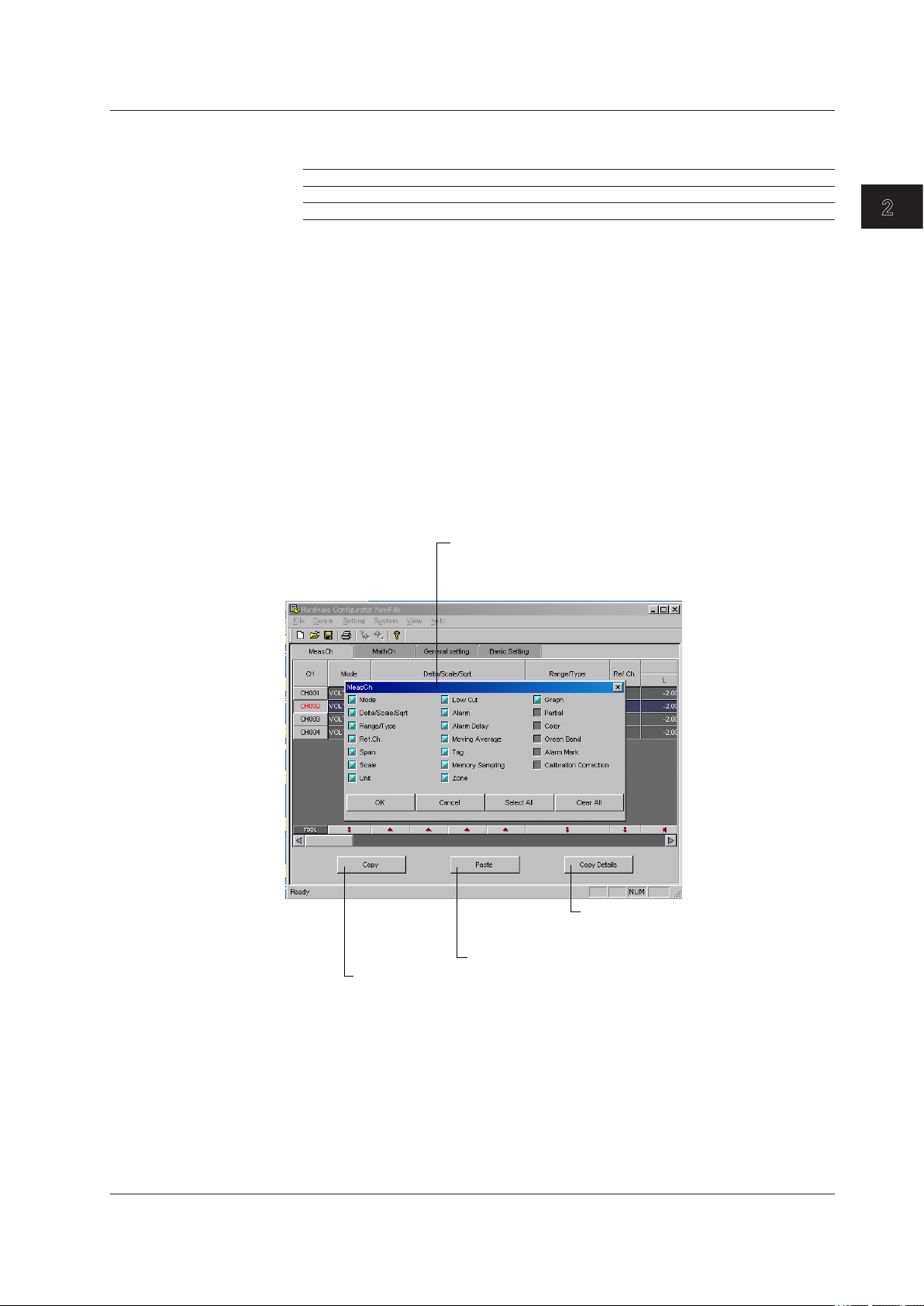
Copying and Pasting Setup Data
You can copy and paste settings using the [Copy], [Paste], and [Copy Details] buttons.
Selecting the Items That You Want to Copy
Click the [Copy Detail] button.
1.
The item selection dialog box opens.
Select the items that you want to copy.
2.
Items with a blue box will be copied.
2.3 Setting the Measurement Channels
2
Configuring the FX1000
Copy the copy source settings
Copying and Pasting Settings
Select the copy source numbers (the [CH] row in this figure) and click the [Copy]
1.
button.
* To specify multiple copy sources, drag over the numbers to select them.
Select the copy destination numbers (the [CH] row in this figure) and click the
2.
[Paste] button.
* To specify multiple copy destinations, drag over the numbers to select them.
The settings are copied and pasted.
the [Copy Detail] button
Setting items appear. An item with a blue box is selected.
An item with a gray box is not selected.
Click this button to open the item
selection dialog box and select the
items that you want to copy
Paste to the copy destination
IM 04L21B01-64EN
2-13
Page 27
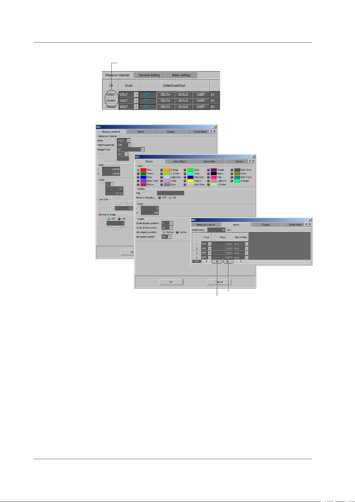
1. Double-click the
2.3 Setting the Measurement Channels
Setting One Channel at a Time
channel you wish to set.
2. The channel setting dialog box opens.
2-14
Set the maximum possible value
Set the minimum possible value
The items in the measurement channel tab can be configured for each channel. The
items that are configured are the same as those configured on the spreadsheet. For
details, see the page corresponding to the item.
IM 04L21B01-64EN
Page 28
1
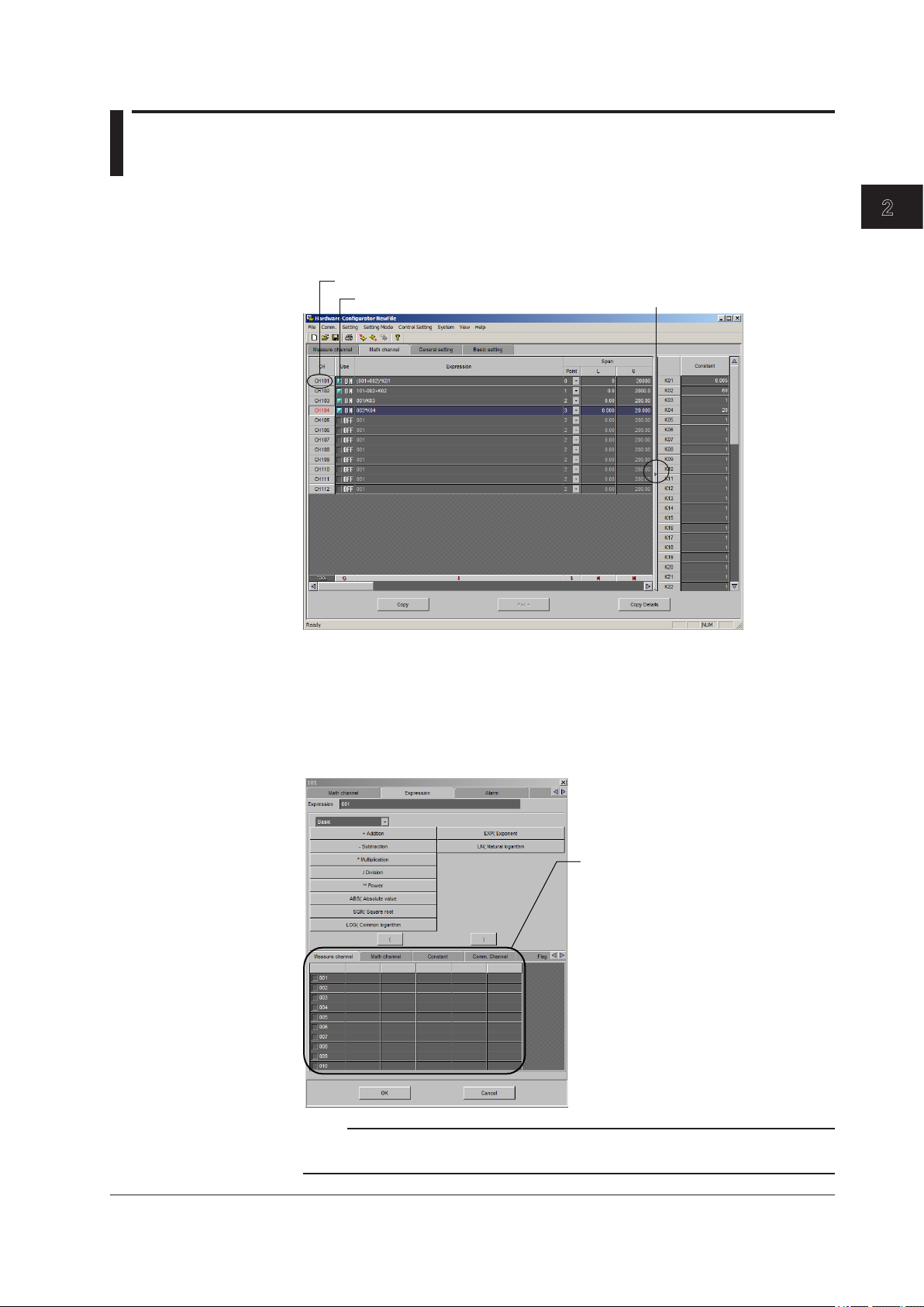
2.4 Setting the Computation Channels
Click this when you want to configure the settings for each channel separately.
The setting operation is the same as for setting the measurement channels.
See pages 2-4 and 2-5 of section 2.3, “Setting the Measurement Channels.”
The items that you can configure vary depending on the system configuration and the
settings.
2
Configuring the FX1000
Turns the computation ON and OFF
Turning Computation ON/OFF
Set whether or not to perform computation for each computation channel (math channel).
Entering Expressions
Enter an expression using up to 120 characters. You can display the variables or constants
list and add one of the variables or constants in the list to your expression simply by
clicking it. For details related to the expression, see the FX User’s Manual.
Shows or hides the constants
Note
Do not include channels that are set to Log scale in a computation channel expression. If you
include these channels, an error will be returned as the measured result.
IM 04L21B01-64EN
Click the tab to display
a list of that item
2-15
Page 29

2.4 Setting the Computation Channels
Span (Display Span) and Point
Sets the upper and lower limits of the display.
The range is from –9999999 to 99999999. Set the number of digits to the right the
decimal to four digits or less (0 to 4).
Unit
Enter the unit using up to six characters.
TLOG (TLOG Computation)
Timer
Select the number of the timer that you want to use.
Sum Scale
Set the sum scale to [/s], [/min], [/h] to match the unit of the measured value.
Example: If the unit of the measured value is “m
If you select [OFF], the measured data is summed as-is once per scan interval.
Reset
To reset the TLOG computed value at each interval, select [ON].
Alarm and Tag
The setting operation is the same as that for setting the measurement channels. See
section 2.3, “Setting the Measurement Channels.”
3
/min,” select [/min].
Rolling Average
ON/OFF
To take the rolling average of the measured results, select [ON].
Interval
Select the sampling interval when taking the rolling average from the following: The
sampling interval takes on a value that is an integer multiple of the scan interval. For
example, if the sampling interval is set to 5 s when the scan interval is 2 s, the actual
sampling interval is 6 s.
Count (Number of samples)
Set the number of samples for the rolling average using an integer between 1 and 1500.
The rolling average time is equal to the sampling interval × the number of samples.
Note
FX Specications
•
If the number of data points to be averaged has not reached the specified number of samples
immediately after computation is started, the average of the available data is calculated.
• Computation error data is excluded from the rolling average computation.
• If the computed data exceeds the upper or lower limit, the data is clipped at the upper or
lower limit, and the rolling average is computed. The upper and lower limit is “±100000000”
excluding the decimal point. The decimal place is the same as that of the span lower limit.
Memory Sampling, Zone, Graph, Partial, Color, Green Band, and Alarm Mark
The setting operation is the same as that for setting the measurement channels. See
section 2.3, “Setting the Measurement Channels.”
Constant
2-16
You can set constants to be used in the expression. Up to 60 constants can be specified.
IM 04L21B01-64EN
Page 30
1
Copying and Pasting Setup Data
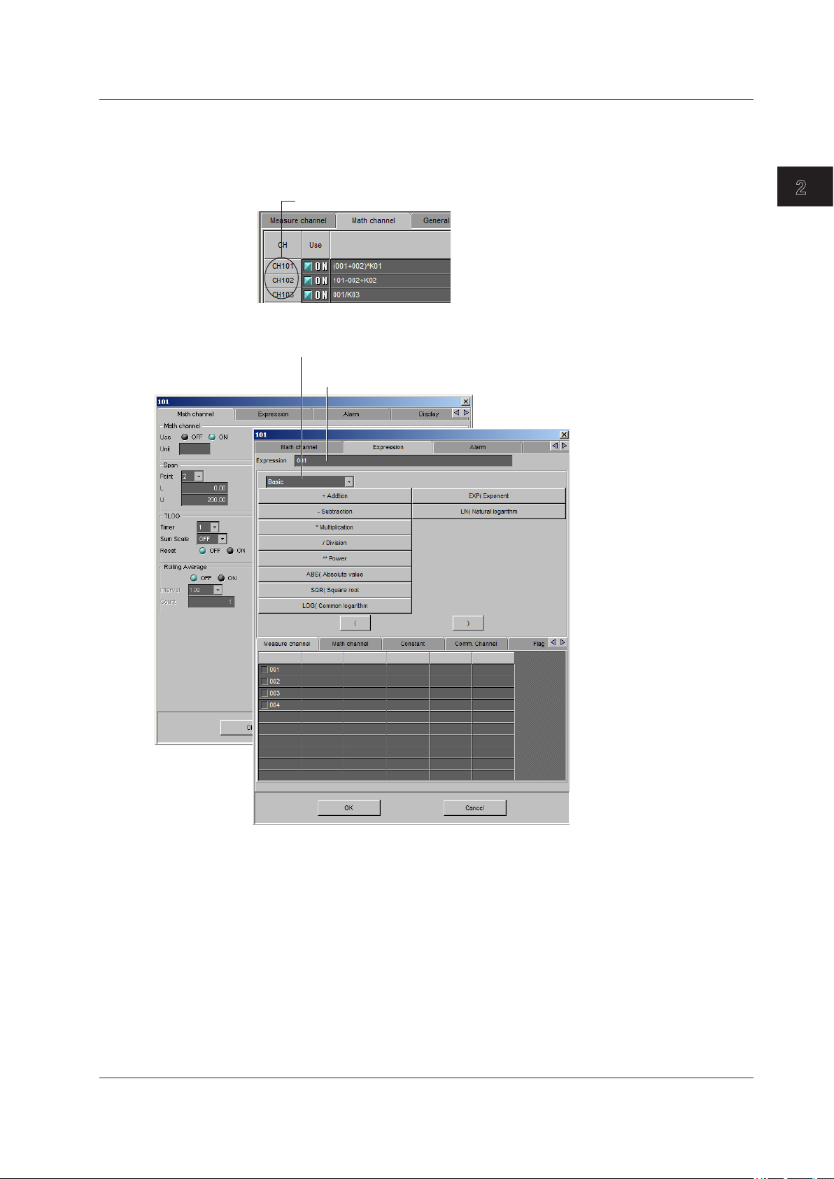
1. Double-click the channel you wish to set.
Clicking here and selecting the list of operators switches the display
See page 2-12 of section 2.3, “Setting the Measurement Channels.”
2.4 Setting the Computation Channels
Setting One Computation Channel (Math Channel) at a Time
2. The channel setting dialog box opens.
Select channels and constants on the Measure channel, Math channel, Constant,
and other tabbed pages and select desired operators to create an expression.
2
Configuring the FX1000
IM 04L21B01-64EN
The items in the [Math channel] tab can be configured for each channel. The items that
are configured are the same as those configured on the spreadsheet. For details, see
the page corresponding to the item.
2-17
Page 31

2.5 Entering General Settings
The items that you can configure vary depending on the system configuration and the
settings.
Daylight Saving Time
Start Time and End Time
Set the date and time at which to switch to daylight saving time and the date and time at
which to switch to standard time.
2-18
IM 04L21B01-64EN
Page 32

1
Group
Click to display the channel configuration/trip
2.5 Entering General Settings
line settings dialog box.
2
Configuring the FX1000
Select channels to register
to the group, or set the trip line.
Channel Configuration
• Use
Select [ON] for the display groups that you want to display. You can set up to 10
groups.
• Group name
Set the group name. (up to 16 characters)
• Channel Configuration
Specify a measurement channel or a computation channel. A group can contain up to
6 channels.
Note
• The trend, digital, and bar graph displays are shown in the specified order.
• A channel can be assigned to multiple groups.
• The same channel cannot be assigned multiple times in a group.
IM 04L21B01-64EN
2-19
Page 33

2.5 Entering General Settings
Trip line
Set lines at specified positions in the waveform display range on the Trend display.
• Use
Turn [ON] the trip lines you want to display.
• Position
Set the position in the range of 0 to 100% of the display width.
• Color
The default colors are red, green, blue, and yellow. If you want to change the color,
• Trend Line
Set the line width of the trip line in dots (1 to 3).
select from the 24 available colors.
2-20
IM 04L21B01-64EN
Page 34

1
Display
2.5 Entering General Settings
Logging
• Trend interval [/div]
This is the trend interval. Select the time corresponding to 1 division of the time axis
on the trend display from below: You cannot set a T-Y interval that corresponds to
a sampling interval that is faster than the scan interval. See the table under “Save
Interval” below.
• Save Interval (when recording display data)
Select the size of a record data le. The recorded data is divided by the le size
specied here. The available settings vary depending on the number of memory
sampling channels and the T-Y interval setting.
T-Y interval 15 s
Selectable range
of auto save
interval
Selectable save
interval values
T-Y interval 10 min 15 min 20 min 30 min 1 h
Selectable range
of auto save
interval
Selectable save
interval values
T-Y interval 2 h 4 h 10 h
Selectable range
of auto save
interval
Selectable save
interval values
1 Selectable on the FX1002 and FX1004
1
500 ms 1 s 2 s 4 s 10 s
10 min to 3
days
20 s 30 s 40 s 1 min 2 min
10 min to 31
days
4 min 8 min 20 min
2 hours to
31 days
30 s 1 min 2 min 5 min
10 min to 7
days
10 min to 31
days
4 hours to
31 days
10 min to 14
days
1 hour to 31
days
8 hours to
31 days
10 min to 14
days
1 hour to 31
days
10 min to 31
days
1 hour to 31
days
2
Configuring the FX1000
IM 04L21B01-64EN
2-21
Page 35

2.5 Entering General Settings
Trend
• Display Update 2nd Interval
Enabled when [Trend Rate Switching] is turned [ON] under [Environment] - [Detail
The selectable 2nd intervals are the same as those for Trend interval.
• Direction
Set the display direction of the trends to [Horizontal], [Vertical], [Wide], or [Split].
• Trend Clear
• Message direction
Set the display direction of messages to [Horizontal] or [Vertical]. When the trend is
• Scale Digit
Select the [Normal] or [Fine].
Fine If the scale value is two-digit display, it can be changed to three digits. For
Setting] in the [Basic Setting] tab. Select a rate from the list.
Settings Description
ON Clears the displayed waveform when the memory sampling is started.
OFF Does not clear the waveform when the memory sampling is started.
set to Vertical, the message direction is xed to [Horizontal].
example, if the scale range is “49.0 to 51.0,” the scale values are displayed
using 3 digits as shown below.
• Value Indicator
The current value is displayed as a mark or a bar graph.
• Trend Line
Set the line width of the trend in dots (1 to 3).
• Grid
Select the number of grids to be displayed in the waveform display area of the trend
display.
Settings Description
4 to 12 Displays a grid that divides the display width into 4 to 12 sections.
Auto Displays the same number of grids as the number of scale divisions of the
first assigned channel of the group.
2-22
IM 04L21B01-64EN
Page 36

1
2.5 Entering General Settings
Display
• Bar Graph Direction
Select Bar graph direction.
• Brightness
You can select a value from 1 to 8 (the default value is 2). Larger the value, brighter
the display becomes.
• Backlight Saver Mode
Settings Description
OFF Disables the backlight saver.
Dimmer Dims the display if there is no operation for a given time.
Timeoff Turns the backlight OFF if there is no operation for a given time.
• Backlight Saver Time
Select a value from 1 min to 1 h. If the specied time elapses without any key
operation or alarm occurrence, the LCD backlight switches to the specied mode.
• Backlight Restore
Settings Description
Key The backlight returns to the original brightness when a key is pressed.
Key&Alarm The backlight returns to the original brightness when a key is pressed or
when an alarm occurs.
• Trend Background
Set the background color of the operation screen to White (default setting) or Black.
• Historical Trend Background
Select the background color of the historical trend display from the following:
Settings: White, Black (default setting), Cream, and Lightgray
• Scroll Time
Set the switching interval from the available settings between 5 s and 1 min. The
groups switch in ascending order.
• Jump Default Display
Returns to a preset display if there is no key operation for a specic time.
Settings Description
1min to 1h Time until switching the display.
OFF Disables the function.
2
Configuring the FX1000
IM 04L21B01-64EN
2-23
Page 37

2.5 Entering General Settings
Message
Enter a message to be written to the group of up to 32 alphanumeric characters.
2-24
IM 04L21B01-64EN
Page 38

1
Timer
2.5 Entering General Settings
2
Configuring the FX1000
Changes the upper/lower display area
Timer used by event action. Used also in the TLOG computation of the computation
function. You can use 4 timers.
When Using an Absolute Timer
• Mode
Select [Absolute].
• Time interval
Select the interval from the available settings between 1min to 24h.
• Ref.time
Set the time in the range of hour 0 to hour 23.
When Using a Relative Timer
• Mode
Select [Relative].
• Time interval
Set in the range from 00:01 (1 min.) to 24:00 (24 hours).
Hour: Set in the range from 0 to 24.
Min: Set in the range from 0 to 59.
• Reset at Math Start
ON Resets the timer when computation is started. The resetting of the timer is not
considered to be a timeout. Even if the timer is used as an event, the action is
not executed.
IM 04L21B01-64EN
2-25
Page 39

2.5 Entering General Settings
Match Time Timer
Set the time match condition used in event action. You can use 4 match time timers.
• Kind
Set the items with check marks in the following table depending on the Kind setting.
• Day
Set the day.
• Week
Set the day of the week.
• Hour:Minute
Set the time in the range of 00:00 to 23:59.
• Timer action
Day Set the time match condition of a day.
Week Set the time match condition of a week.
Month Set the time match condition of a month.
Setup Item Kind
Daily Weekly Monthly
Day
Week
Hour:Minute
Settings Description
Single Executes the action once when the condition is met.
Repeat Executes the action at every specified time.
2-26
IM 04L21B01-64EN
Page 40

1
Event Action
2.5 Entering General Settings
2
Configuring the FX1000
Math Start
Settings Description
Off Does not start the computation even when the START key is pressed.
Start Starts the computation when the START key is pressed.
Reset Start Resets the computed result up to then and starts the computation when
the START key is pressed.
Event
These are the conditions that must be met for an action to be performed. You can set up
to 40 event actions.
Settings Event action description
NONE Not use.
Remote Select the remote control input terminal number.
Relay Select the alarm output relay number.
Switch Select the internal switch number.
Timer Select the timer number.
Match Time Select the match timer number.
Alarm User Key -
IM 04L21B01-64EN
2-27
Page 41

2.5 Entering General Settings
Action
The action to be executed when an event occurs.
Settings Description
Memory Start/Stop Memory Start Memory Stop Trigger Can be specified when the FX is configured to record event data.
AlarmACK This cannot be specified when the event is set to [Relay], [Switch], or
Math Start/Stop
MathStart
MathStop
Math Reset
Save Display Data Can be specified when the FX is configured to record display data.
Save Event Data Can be specified when the FX is configured to record event data.
Message Set the message number and the destination. Set the message
Snapshot Display Update Interval
Change
Manual Sample Timer Reset Cannot be specified when the event is set to [Timer].
Display Group Change Specify the number of the group to be displayed.
Flag
Time ADJUST Can be specified only when the event is set to [Remote].
Panel Load
1
1
1
1
[Alarm].
-
-
-
-
destination to all groups (All) or a group number.
Can be specified when the function for switching between the trend
update interval and the secondary update interval is enabled.
1
2
-
Can be specified only when the event is set to [Remote].
1 This can only be specified for models that have the /M1, /PM1, or /PWR1 option.
2 This can only be specified when an external storage medium is connected to the FX.
2-28
IM 04L21B01-64EN
Page 42

1
File
2.5 Entering General Settings
2
Configuring the FX1000
Directory name
Set the name of the directory on the storage medium for saving the data on the external
storage medium. (Up to 20 characters)
Symbols that can be used: #, %, (, ), +, -, ., @, °, and _.
Strings that cannot be used: AUX, CON, PRN, NUL, CLOCK, COM1 to COM9, and LPT1
to LPT9.
Header
Set the header comment to be written to the data file (Up to 50 characters).
Structure
Sets the structure of the file name when saving data.
Settings Description
Date Serial number + user-assigned character string + date
Serial Serial number + user-assigned character string
Batch Serial number + batch name (when using the batch function)
File name
Set the user-assigned section of the file name. (Up to 16 characters)
Symbols that can be used: #, %, (, ), +, -, ., @, °, and _.
Field Title, Field Characters
Set text strings.
Title: Up to 20 characters. Characters: Up to 30 characters.
There are 8 fields.
IM 04L21B01-64EN
2-29
Page 43

2.5 Entering General Settings
Event Data
Event related settings are enabled when [Data Kind] is set to [E+D] or [Event] in [Basic
Environment] under [Environment] in the [Basic Setting] tab.
Sample rate
Select the data recording interval from the available settings. See the description for “Data
length” below. You cannot specify a sampling rate that is faster than the scan interval.
Mode
Settings Description
Free Records data continuously.
Single Records data when the trigger condition is met.
Repeat Records data each time the trigger condition is met.
Data length
Select the size of a record data file. The recorded data is divided by the file size
specified here. The available data lengths vary depending on the number of memory
sampling channels and the Sample rate setting.
Sample rate
Selectable range
of data length
Sample rate
Selectable range
of data length
Sample rate
Selectable range
of data length
1
125 ms 250 ms 500 ms 1 s 2 s
10 min to
1 day
1
5 s 10 s 30 s 1 min 2 min
10 min to
31 days
1
5 min 10 min
1 hour to
31 days
1 You cannot choose an interval that is faster than the scan interval.
10 min to
2 days
10 min to
31 days
1 hour to
31 days
10 min to
3 days
1 hour to
31 days
10 min to
7 days
1 hour to
31 days
10 min to
14 days
1 hour to
31 days
Pre-Trigger
Specify the range when recording data before the trigger condition is met. Select the
range as a percentage of the data length from 0, 5, 25, 50, 75, 95, and 100%. If you do
not want to record the data existing before the trigger condition is met, select 0%.
Trigger Signal Key
Select [ON] if you want to activate the trigger using key operation.
2-30
IM 04L21B01-64EN
Page 44

1
Custom Menu
Click to select
2.5 Entering General Settings
You can show or hide items on the menu that appears when you press the FUNC key
and on the display selection menu, which appears when you press the DISP/ENTER key.
Main Menu
The display selection menu appears when the DISP/ENTER key is pressed.
Type of main menus being set
Sub menu
Changes the left/right display area
Delete selected items
Click to display a sub menu on the right side of the screen
Add an item beneath the selected item
For details on the menu, see section 5.16 in the FX User’s Manual.
Function
The FUNC key menu appears when the FUNC key is pressed.
2
Configuring the FX1000
For information about the menu, see section 4.1 in the FX User’s Manual.
IM 04L21B01-64EN
2-31
Page 45

2.5 Entering General Settings
Aux
Power
• VT ratio
Specify a value between 1.0 and 6000.0. The decimal place is xed.
• Point
Set the CT ratio’s decimal place to 0, 1, or 2. This number represents the number of
• CT ratio
The setting range varies depending on the decimal place.
• Low-cut power
Specify a value between 0.05 and 20.00. The decimal place is xed.
digits after the decimal point.
Setting Range Decimal Place
10000 to 32000 0
1000.0 to 9999.9 1
0.05 to 999.99 2
Note
Set the VT ratio and CT ratio so that they meet the following condition.
• Secondary rated power × VT ratio × CT ratio < 10 GW.
Phase and Wire System Input Voltage Secondary Rated Power (W)
1P2W 120 100
240 200
1P3W 240 200
3P3W 120 200
240 400
2-32
IM 04L21B01-64EN
Page 46

1
2.6 Entering Basic Settings
The items that you can configure vary depending on the system configuration and the
settings.
Environment
Basic Environment
2
Configuring the FX1000
• Data Kind
Settings Description
Display Records display data.
E+D Records display data and event data. You cannot select [E+D] when [Trend
Rate Switching] under [Environment] - [Detail Setting] under the [Basic
setting] tab is set to [ON].
Event Records event data.
• Temperature Unit
Select C or F.
• Time zone
Set the time zone of the region in which the FX will be used in terms of the time
difference from GMT.
• Time deviation limit
Current time
Time deviation limit
When the time deviation between the time on the FX and the specied time is within
±(the value specied here), the time on the FX is gradually corrected. Otherwise, the
clock is corrected immediately.
Select from 10 s to 5 min. Select [OFF] to disables the function.
Example: If [Time deviation limit] is set to 10s and the time on the FX is 10 hours 21 minutes
15 seconds, the time on the FX is gradually corrected if the specified time is between
10 hours 21 minutes 5 seconds and 10 hours 21 minutes 25 seconds.
Specified time
IM 04L21B01-64EN
2-33
Page 47

2.6 Entering Basic Settings
• Date format
Settings Display Example
Y/M/D 2011/11/30
M/D/Y 11/30/2011
D/M/Y 30/11/2011
D.M.Y 30.11.2011
Applied Range
The format is applied to the date displayed on the screen. It does not change the
date format on the setup screen of the date/time, the date in the output data via
communications, the date saved along with the data, and the date used in the data le
names.
• Service port
The following table indicates the number of simultaneous uses (number of users that
can use the function simultaneously), the maximum number of connections, and the
port number for each function.
Function Maximum
Number of
Connections
FTP server 2 2 2
Web server (HTTP) 1 – – 80/tcp
SNTP server – – – 123/udp
Modbus server 2 – – 502/tcp
1 There are user limitations. For details, see the FX1000 Communication Interface Manual (IM
04L21B01-17EN).
2 The default port number. You can set the value in the range of 1 to 65535. Use the default
port number unless there is a special reason not to do so.
Number of Simultaneous Uses Port No.
Administrator User
1
21/tcp
2
2
2
2
• Status Relay Details
Memory/Media Information, Measurement Error, Communication Error,
Memory Stop
The relay contact output is turned on when an item that is set to [ON] occurs.
2-34
IM 04L21B01-64EN
Page 48

1
2.6 Entering Basic Settings
Detail Setting
2
Configuring the FX1000
• Tag
Settings Description
Tag Displays tags. Channel numbers are displayed for channels that do not have
tags assigned to them.
Channel Displays channel numbers.
• Language
Select the display language
• Decimal Point Type
You can set the decimal point type for the display and les saved in text format. You
can select [Point] or [Comma].
• Batch
Select [ON] to use the batch function.
• Digit of lot number
Select the number of digits of the lot number from 4, 6, or 8. Select [OFF] to disable
the lot number.
• Auto increment
ON Automatically sets the lot number of the next measurement to “the lot number of
the current measurement + 1.”
• Partial
Turn Partial [ON] (partially expand) or [OFF] (do not partially expand).
• Trend Rate Switching
ON Enables the function that switches the trend interval while the memory sampling
is in progress. The “Second interval [/div]” item is displayed in the setting mode.
• When [Trend Rate Switching] is set to [ON], you cannot set [Data Kind] under [Environment]
- [Basic Environment] in the [Basic setting] tab to [E+D].
• Write Group
Settings Description
Common Write the message to all groups.
Separate Write the message to the displayed group.
IM 04L21B01-64EN
2-35
Page 49

2.6 Entering Basic Settings
• Power-Fail Message
ON A message is written when the FX recovers from a power failure while
memory sampling is in progress.
• Change Message
ON Writes the time the interval is switched and the new trend interval as a
message when the trend interval is switched.
• Scale over
Settings Description
Free The value is set to –over range if the value is less than –30000 and +over range
if the value is greater than 30000 excluding the decimal point. The value is
displayed as –Over and +Over, respectively.
Over The value is set to –over range if the value is less than –5% of the scale and +over
range if the value is greater than 105%. The value is displayed as –Over and
+Over, respectively.
Example: If the scale is 0.0 to 200.0, a value less than –10.0 results in a –over range, and a
value greater than 210.0 results in a +over range.
Note
For computations such as TLOG, CLOG, and report, the handling of the scale over-range value
can be set in advance.
• Key Security
Settings Description
Login Enables only registered users to operate the FX using keys. The [User
registration] is displayed in the [Basic Setting] tab.
Keylock Enables the key lock function. Set the key lock function in the [Basic Setting] tab.
OFF Disables the security functions.
• Comm. Security
Settings Description
Login Enables only registered users to operate the FX via communications. The [User
registration] is displayed in the basic setting mode menu.
OFF Disables the security functions.
• Auto Save
Settings Description
ON Automatically saves the measured data to the CF card.
OFF Does not automatically save the data. Save the measured data manually to
the CF card or USB flash memory (/USB1 option).
• Media FIFO
This is valid only when [Auto Save] is [ON].
Settings Description
ON If there is no more free space on the CF card, the oldest file is deleted, and the
newest file is saved.
OFF If there is no more free space on the CF card, the measured data is not saved
to the CF card.
2-36
IM 04L21B01-64EN
Page 50

1
2.6 Entering Basic Settings
Option
2
Configuring the FX1000
• Value on Error
Specify whether to set the display for a computation error to [+Over] or [–Over].
• Overflow Sum, Ave
Specify how to handle overow data when it is detected in the SUM or AVE
computation of TLOG or CLOG. This setting is also applied to report generation.
Settings Description
Error Sets the computed result to computation error.
Skip Discards the overflow data and continues the computation.
Limit Uses a limit value in place of the overflow data and continues the computation.
• Overflow Min, Max, P-P
Specify how to handle overow data when it is detected in the MAX, MIN, or P-P
computation of TLOG or CLOG. This setting is also applied to report generation.
Settings Description
Over Uses the overflow data as-is.
Skip Discards the overflow data and continues the computation.
• Report (1 to 4)
Select the type of data to output as reports.
Settings Description
OFF Does not output reports. You cannot set Report 1 to [OFF].
Ave Outputs the average value.
Max Outputs the maximum value.
Min Outputs the minimum value.
Sum Outputs the sum value.
Instant Outputs the instantaneous value.
• File kind
Specify the method used to create report les.
Settings Description
Split Saves each type of report to a separate file.
Combined Saves the report data of two types in a single file.
IM 04L21B01-64EN
2-37
Page 51
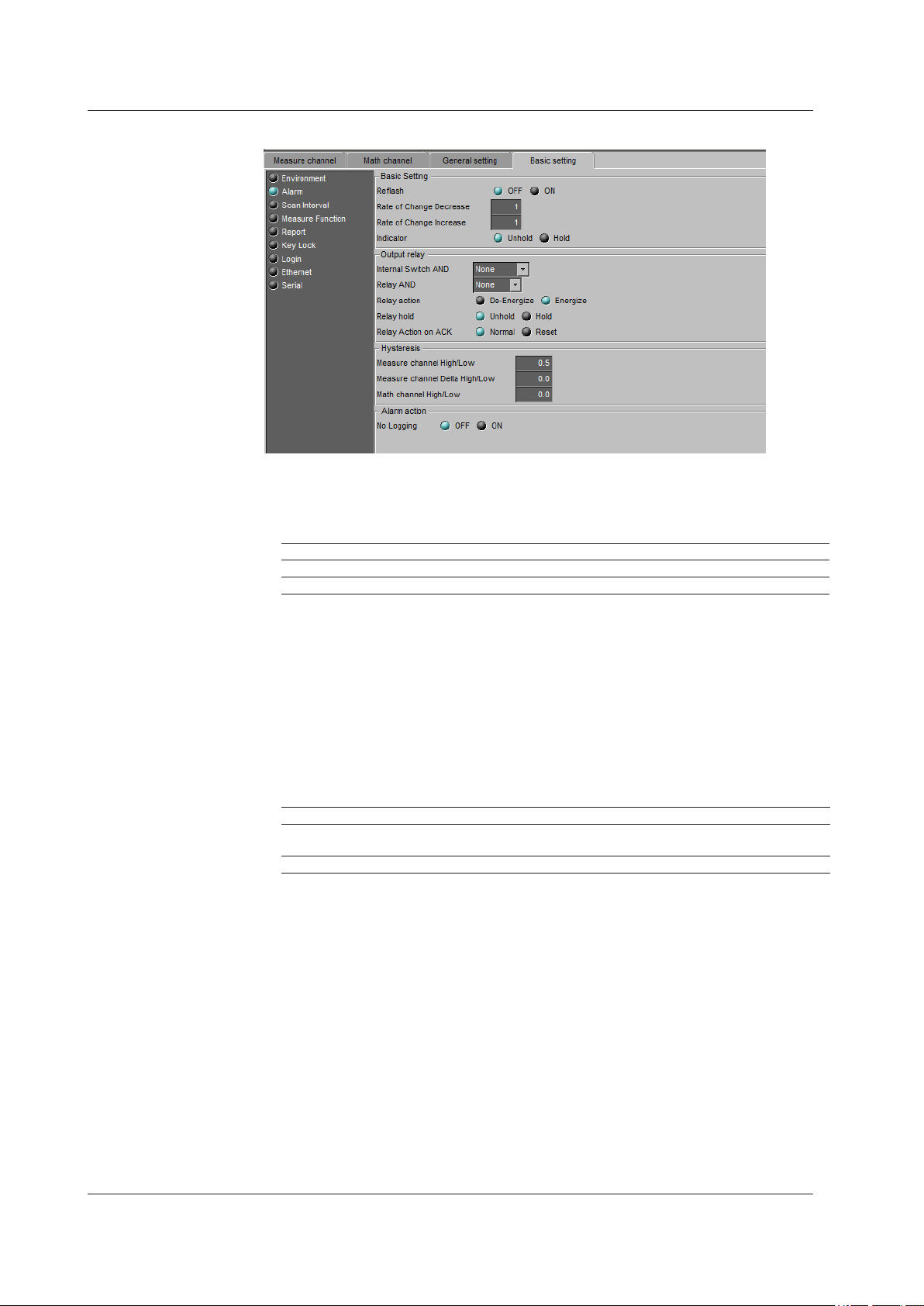
2.6 Entering Basic Settings
Alarm
Basic Setting
• Reflash
To set the reash operation on the alarm output relay, select [ON]. The reash
function is set on the rst three output relays.
Settings Description
Off Reflash is not used.
On Reflash is used. The relays are deactivated for approximately 500 ms.
• Rate of Change Decrease
Set the interval for the rate-of-change calculation of the low limit on rate-of-change
alarm in terms of the number of sampled data points (1 to 32). The actual interval is
obtained by multiplying the value specied here by the scan interval.
• Rate of Change Increase
Set the interval for the rate-of-change calculation of the high limit on rate-of-change
alarm in the same manner as the interval for the low limit on rate-of-change alarm.
• Hold
You can choose to make the alarm displays behave in the following ways.
Settings Description
Unhold Clears the alarm indication when the alarm condition is released (returns to
normal condition).
Hold Holds the alarm indication until an alarm acknowledge operation is performed.
Output relay
• Internal Switch AND
Select the internal switches that are to operate using AND logic. Set the range of
internal switches (from the rst internal switch) to take the AND logic. All subsequent
switches will be set to OR logic.
2-38
IM 04L21B01-64EN
Page 52

1
2.6 Entering Basic Settings
• Relay AND
Select the relays that are to operate using AND logic. Set the range of relays (from
the rst alarm relay) to take the AND logic. All subsequent relays will be set to OR
logic. Available settings are [None], [I01] (I01 only), [I01-I02] (I01 and I02), [I01-I03] (I01
to I03), etc. Only alarm output relays that are installed are valid.
• Relay action
Select whether the alarm output relay is energized or de-energized when an alarm
occurs. The setting applies to all alarm output relays.
• Relay hold
You can choose to make the alarm output relays behave in the following ways. This
setting applies to all relays.
Settings Description
Unhold Turns the output relay OFF when the alarm condition is released (returns to
normal condition).
Hold Holds the output relay at ON until an alarm acknowledge operation is performed.
Relay Action on ACK
•
Settings Description
Normal The relay output is deactivated when the alarm ACK operation is executed. If the
condition for activating the alarm output relay is met in the next scan interval, the
relay output is activated.
This operation is valid only when the alarm output relay is set to [Hold].
Reset The relay output is deactivated when the alarm ACK operation is executed. If a
new condition for activating the alarm output relay, the relay is activated.
2
Configuring the FX1000
Note
When reflash is turned ON, the operation of the first three output relays is set to nonhold.
Specifying Hold produces no effect.
Hysteresis
• Measure channel High/Low
Sets the hysteresis width of the alarm occurrence/release of the high/low limit alarm
specied on measurement channels.
Selectable range: 0.0% to 5.0% of the span or scaling width
• Measure channel Delta High/Low
Sets the hysteresis width of the alarm occurrence/release of the difference high/low
limit alarm specied on measurement channels.
Selectable range: 0.0% to 5.0% of the span
• Math channel High/Low
Sets the hysteresis width of the alarm occurrence/release of the high/low limit alarm
specied on computation and external input channels.
Selectable range: 0.0% to 5.0% of the measurement span
Alarm action
• No Logging
Select [ON] to hide alarm indication. The [Detect] setting is enabled in the [Measure
channel], [Math channel] tab(s).
This function disables the alarm indicator and the logging of alarm events to the alarm
summary.
IM 04L21B01-64EN
2-39
Page 53

2.6 Entering Basic Settings
Scan Interval
Scan interval
Select the scan interval.
A/D integrate
Select the A/D integration time as necessary. Only the selectable settings are displayed.
Settings Description
Auto The FX automatically detects the power supply frequency and sets the integration
time to 16.7 ms and 20 ms for 60 Hz and 50 Hz, respectively. Fixed to 20 ms on
/P1 models that use the 24 VDC power supply.
50Hz Sets the integration time to 20 ms.
60Hz Sets the integration time to 16.7 ms.
100ms Sets the integration time to 100 ms (when the scan interval is 2 s or 5 s).
2-40
IM 04L21B01-64EN
Page 54

1
Measure Function
2.6 Entering Basic Settings
2
Configuring the FX1000
Burnout
Thermocouple input
Settings Description
OFF Sensor disconnections are not detected.
UP When the sensor burns out, the measured result is set to +over range. The
measured value displays “Burnout.”
For 1-5V input, the FX assumes that the sensor has burned out when the
measured value exceeds the scale upper limit by 10% of the scale width.
(Example: When the measured value is greater than 110 when the scale is from 0
to 100)
DOWN When the sensor burns out, the measured result is set to –over range. The
measured value displays “Burnout.”
For 1-5V input, the FX assumes that the sensor has burned out when the
measured value falls below the scale lower limit by 5% of the scale width.
(Example: When the measured value is less than –5 when the scale is from 0 to
100)
RJC
• Mode
Sets the reference junction compensation method of the thermocouple input. Select
[Internal] or [External].
Settings Description
Internal Uses the reference junction compensation function of the FX.
External Uses an external reference junction compensation function. When set to
[External], [Volt] is displayed.
• RJC voltage (µV)
The compensation voltage to be added to the input. Set the value in the range of
–20000 µV to 20000 µV.
IM 04L21B01-64EN
2-41
Page 55

Click to display the channel selection screen.
2.6 Entering Basic Settings
Report
Channel selection screen
Click the channel you wish to set up
Report setting
• Report kind
Select the type of report to be created.
Settings Description
OFF Do not create a report.
Hour Creates hourly reports.
Day Creates daily reports.
Hour+Day Creates hourly and daily reports.
Day+Week Creates daily and weekly reports.
Day+Month Creates daily and monthly reports.
• Day, Week day, and Time
Set the date or day of the week and the time when the report is to be created. The
specied date/time is when the report le is divided. Set the values in the range
indicated below. Items with a dash are invalid.
Report Type Day Week day Time
Hour - - 0 to 23
Day 1 to 28* - 0 to 23
Hour+Day - - 0 to 23
Day+Week - SUN to SAT 0 to 23
Day+Month 1 to 28* - 0 to 23
* You cannot specify 29, 30, or 31.
Report channel setting
• Use
Select [ON] for the report channels to be used.
• CH No.
Set the channel to assign to the report channel. All channels can be assigned, but
reports are not created for channels set to [Skip] or [OFF] even if they are assigned.
In the stacked bar graph display, report data is displayed in the following groups.
However, only channels that have the same unit as the rst group in the channel are
displayed.
No. 1 2 3 4
Report Groups R01 to R06 R07 to R12 R13 to R18 R19 to R24
2-42
IM 04L21B01-64EN
Page 56

1
2.6 Entering Basic Settings
Note
You cannot create reports for channels that are set to Log scale (/LG1 option). An error will be
returned as the result of report computations on channels that are set to Log scale.
• Sum Scale
Set the sum scale to [/s] to [/day] to match the unit of the measured value.
Example: If the unit of the measured value is “m
If you select [OFF], the measured data is summed as-is once per scan interval.
3
/min,” select [/min].
2
Configuring the FX1000
IM 04L21B01-64EN
2-43
Page 57

2.6 Entering Basic Settings
Key Lock
Enabled when [Key Security] is set to [Keylock] under [Environment] - [Detail Setting] in
the [Basic Setting] tab.
Password
The password used to release the key lock. The password is displayed as a string of
asterisks. (Use up to eight characters.)
Key, Function, Media/USB
Select whether or not to disable each item.
Settings Description
Free Key lock not applied.
Lock Disables the operation.
2-44
IM 04L21B01-64EN
Page 58

1
Login
2.6 Entering Basic Settings
You can set the [Login] when [Login] is selected as [Key Security] or [Comm. Security]
under [Environment] - [Detail Setting] in the [Basic Setting] tab.
Supervisor (Administrator)
• Auto Logout Time
Settings Description
OFF Does not log out until the logout operation is executed.
1min to 10min Automatically logs out when there is no key operation for a specified time.
2
Configuring the FX1000
• Logout Operation
Settings Description
OFF Only login operation is available.
Logout Operation
Display
Allows the user to switch the operation screen in addition to the login
operation.
• Mode
The choices differ depending on the selected contents of [Key Security] and [Comm.
Security] under [Environment] - [Detail Setting] in the [Basic Setting] tab.
Settings Description
OFF Not register.
Key Log into the FX using keys.
Comm Log into the FX via communications.
Web Log into the operator page and monitor page of the FX using a Web
browser.
Key+Comm Log into the FX using keys and via communications.
• User Name
Set the user name. (Up to 20 characters)
You cannot register user names that are already registered.
You cannot register “quit” or a user name containing all spaces.
• Password
Set the password. (Up to 8 characters.)
The entered password is displayed as a string of asterisks.
You cannot register a character string that contains spaces or a password containing
all spaces.
IM 04L21B01-64EN
2-45
Page 59

2.6 Entering Basic Settings
User
Up to 30 names can be registered.
Changes the upper/lower display area
• Mode
The available settings vary depending on the [Security] setting.
Settings Description
OFF Not register.
Key Log into the FX using keys.
Comm Log into the FX via communications.
Web Log into the monitor page of the FX using a Web browser.
Key+Comm Log into the FX using keys and via communications.
• User Name, Password
Same as the supervisor settings.
• Key Lock No.
Settings Description
OFF No limitations on the operation.
1 to 10 Registration number of the operation limitation.
• Key, Function, Media/USB
Select whether or not to disable each item.
Settings Description
Free Key lock not applied.
Lock Disables the operation.
2-46
IM 04L21B01-64EN
Page 60

1
Ethernet
2.6 Entering Basic Settings
TCP/IP
2
Configuring the FX1000
The settings vary depending on how the IP address is acquired.
Consult with your network administrator for the network parameters such as the IP
address, subnet mask, default gateway, and DNS.
When using a fixed IP address
• DHCP
Set [DHCP] to [OFF].
• Host Name
Set the FX’s host name using up to 64 alphanumeric characters. You do not have to
set this parameter.
• IP Address
Set the IP address to assign to the FX.
• Subnet Mask
Set the subnet mask according to the system or network to which the FX belongs.
• Default Gateway
Set the IP address of the gateway.
• Domain Name
Set the network domain name that the FX belongs to using up to 64 characters. You
do not have to set this parameter.
• Server Primary, Server Secondary
Register up to two IP addresses for the primary and secondary DNS servers.
• Domain Primary, Domain Secondary
Set up to two domain sufxes: primary and secondary.
When obtaining the IP address from DHCP
• DHCP
Select [ON].
• Host Name
Use up to 64 alphanumeric characters to set the FX host name.
• DNS accession
To automatically obtain the DNS server address, select [ON]. Otherwise, select [OFF].
If you select [OFF], you must set the IP address of the DNS server.
IM 04L21B01-64EN
2-47
Page 61

2.6 Entering Basic Settings
• Domain Name
Set the network domain name that the FX belongs to using up to 64 characters. This
is enabled when “DNS accession” is set to [Not].
• Server Primary, Server Secondary
Register up to two IP addresses for the primary and secondary DNS servers.
• Domain Primary, Domain Secondary
Set up to two domain sufxes: primary and secondary.
Control
• Keep Alive
To disconnect when there is no response to the test packets that are periodically sent,
select [ON]. Otherwise, select [OFF].
• Time out
To use the application timeout function, select [ON]. Otherwise, select [OFF]. If you
select [ON], a [Timeout time] is displayed.
•
Timeout value (min.)
Set the timeout value between 1 and 120 (minutes).
• Host-Name Register
To automatically register the host name, select [ON].
Checking the communication status
The Ethernet communication status can be confirmed with the LED lamp that is provided
on the Ethernet connector on the FX rear panel or the [Ethernet link] that is shown at the
upper right of the basic setting screen.
2-48
IM 04L21B01-64EN
Page 62

1
2.6 Entering Basic Settings
FTP
2
Configuring the FX1000
FTP Transfer File
Data files that are set to [ON] are automatically transferred to the FTP destination.
File Type Description
Display data file Data files are automatically transferred at each file save interval.
Event data file Files are automatically transferred when the data length of data is recorded.
Report file Data files are automatically transferred every time a report is created.
Snapshot data file The files are automatically transferred when a snapshot is executed.*
* Indicates snapshot using the FUNC key, communication command (EV2 command), USER
key, or remote control function.
Setting the FTP connection destination
Consult your network administrator when setting parameters such as the primary/
secondary FTP servers, port number, login name, password, account, and availability of
the PASV mode.
• Primary, Secondary
You can specify two destination FTP servers, [Primary] and [Secondary]. If the
primary FTP server is down, the le is transferred to the secondary FTP server.
• Server Name
Enter the name of the le transfer destination FTP server using up to 64 alphanumeric
characters.
• If the DNS is used, you can set the host name as a server name.
• You can also set the IP address. In this case, the DNS is not required.
• Port No.
Enter the port number of the le transfer destination FTP server in the range of 1 to
65535. The default value is 21.
• Login Name
Enter the login name for accessing the FTP server using up to 32 alphanumeric
characters.
• Password
Enter the password for accessing the FTP server using up to 32 alphanumeric
characters. The password is displayed as a string of asterisks.
• Account
Enter the account (ID) for accessing the FTP server using up to 32 alphanumeric
characters.
IM 04L21B01-64EN
2-49
Page 63

2.6 Entering Basic Settings
• PASV
Select [ON] when using the FX behind a rewall that requires the passive mode. The
default setting is [OFF].
• Initial Path
Enter the directory of the le transfer destination using up to 64 alphanumeric
characters. The delimiter for directories varies depending on the implementation of
the destination FTP server.
Example: When transferring les to the “data” directory in the “home” directory of
an FTP server on a UNIX le system.
/home/data
Note
If the file transfer to both primary and secondary destinations fails, the FX aborts the file
transfer. When the connection recovers, the FX transfers the data that could not to be
transferred in addition to the new data file. However, since the data that is transferred resides
in the internal memory of the FX, if the data is overwritten, the data that could not be transferred
is lost.
2-50
IM 04L21B01-64EN
Page 64

1
2.6 Entering Basic Settings
MODBUS Client
2
Configuring the FX1000
Changes the upper/lower display area
Basic Setting
• Communication interval
Set the read cycle to 1s, 2s, 5s, or 10s.
• Auto recovery
Set the interval for retrying the connection when it is interrupted for some reason.
Select OFF, 10s, 20s, 30s, 1min, 2min, 5min, 10min, 20min, 30min, or 1h.
Modbus Server setting
• Server No.
Select from 1 to 16 for the server registration numbers to be congured.
• Host Name
Set the destination Modbus server name using up to 64 alphanumeric characters.
• If the DNS is used, you can set the host name as a server name.
• You can also set the IP address. In this case, the DNS is not required.
• Port No.
Enter the port number in the range of 0 to 65535 for the selected server. The default
value is 502.
• Unit
Select [Auto] if the unit number of the destination server is not required; Otherwise,
select [Fixed]. If you select [Fixed], the [Unit No.] item is displayed.
• Unit No.
Enter a xed unit number in the range of 0 to 255.
Command setting
• Command
Set the command type.
Settings Description
R-Math Read to the communication input data (32-bit floating point type) from the
server.
Write Write the measurement channel (16-bit signed integer type) to the server.
W-Math Write the computation channel (32-bit signed integer type) to the server.
You can only select [R-Math] or [W-Math] on models that have the /M1, /PM1, or /PWR1
option.
IM 04L21B01-64EN
2-51
Page 65

2.6 Entering Basic Settings
• Start channel and End channel (FX channels)
Enter the rst and last channel numbers of input/output. The channel numbers that
you can specify vary depending on the command type and are shown below. However,
the total number of channels that you can specify varies depending on the model.
R-Math: C01 to C24, Write: 1 to 12, W-Math: 101 to 124
• Connected to (server number)
Select the server number from 1 to 16.
• Register
Set the register number of the server.
You can specify an input register in the range of 30001 to 39999 or 300001 to 365536.
You can specify a hold register in the range of 40001 to 49999 or 400001 to 465536.
The register numbers you can specify vary depending on the command type. See
section 6.3 in the FX1000 Communication Interface User’s Manual, IM 04L21B0117EN.
• Type
Select INT16, UINT16, INT32_B, INT32_L, UINT32_B, UINT32_L, FLOAT_B, or
FLOAT_L.
The types that you can specify vary depending on the type of command. See section 6.3
in the FX1000 Communication Interface User’s Manual, IM 04L21B01-17EN.
2-52
IM 04L21B01-64EN
Page 66

1
2.6 Entering Basic Settings
E-mail
2
Configuring the FX1000
Set the SMTP server and mail recipient addresses.
Basic Setting
• SMTP server name
Enter the host name or IP address of the SMTP server.
• Port No.
Unless specied otherwise, set the number to the default value. The default value is 25.
• Security
Select [POP before SMTP] if you need to enable POP before SMTP. To enable
authenticated e-mail transmission (Authentication SMTP), select [Auth].
• Address 1, Address 2
Enter the e-mail address. Multiple e-mail addresses can be entered in the box of one
recipient. When entering multiple addresses, delimit each address with a space. Up
to 150 characters can be entered.
• Sender
Enter the sender e-mail address. You can enter up to 64 characters.
POP3 settings
• POP3 Server name
Enter the POP3 server host name or IP address.
• Port number
Use the default setting unless you need to change it. The default value is 110.
• Login name
Enter the POP3 server login name.
• Password
Enter the POP3 server login password using up to 32 characters. The password is
displayed as a string of asterisks.
IM 04L21B01-64EN
2-53
Page 67

2.6 Entering Basic Settings
• Send delay [second]
Set the delay between POP3 server authentication and transmission to a value from 0
to 10 seconds.
• POP3 Login
To encrypt the password when logging into the POP3 server, select APOP. To send it
in plain text, select PLAIN.
Auth. Settings
To enable support for authenticated e-mail transmission (Authentication SMTP), set a
user name and password to use for authentication.
• User name
Enter the user name. You can enter up to 32 characters.
• Password
Enter the password. You can enter up to 32 characters. The password is displayed as
a string of asterisks.
Alarm
Specify the settings for sending e-mail when alarms occur.
• Recipient1 and Recipient2
Set the e-mail recipients. For Recipient1 and Recipient2, select [ON] to send e-mail
or [OFF] to not send e-mail.
• Active alarms
Sends an e-mail when an alarm occurs. You can select [ON] (send e-mail) or [OFF] (not
send e-mail) for alarms 1 to 4.
• Include INST
Select [ON] to attach instantaneous value data to e-mail. The data that is attached
to an e-mail is the instantaneous value that is measured at the time the e-mail is
transmitted.
• Include source URL
Select [ON] to attach the source URL. Attach the URL when the Web server is
enabled.
• Subject
Enter the subject of the e-mail using up to 32 alphanumeric characters. The default
setting is Alarm_summary.
• Header1, Header2
Enter header 1 and header 2 using up to 64 characters.
2-54
IM 04L21B01-64EN
Page 68

1
2.6 Entering Basic Settings
Scheduled
2
Configuring the FX1000
Specify the settings for sending e-mail at scheduled times.
• Recipient1
Set the e-mail recipients. For Recipient1 and Recipient2, select [ON] to send e-mail
or [OFF] to not send e-mail.
• Interval
Select the interval for sending e-mail to Recipient1 and Recipient2 from 1, 2, 3, 4, 6, 8,
12, and 24 hours.
• Ref. time
Enter the time used as a reference for sending the e-mail at the specied interval to
Recipient1 and Recipient2.
• Include INST, Include source URL, Subject, and Header
See the explanation of alarm mail. The default subject is Periodic_data.
IM 04L21B01-64EN
2-55
Page 69

2.6 Entering Basic Settings
System
Specify the settings for sending e-mail when the FX recovers from a power failure, at
memory end, and when an error occurs.
• Recipient1 and Recipient2
Set the e-mail recipients. For Recipient1 and Recipient2, select [ON] to send e-mail
or [OFF] to not send e-mail.
• Include source URL, Subject, and Header
These items are the same as the e-mail that is sent when an alarm occurs. The
default subject is System_warning.
2-56
IM 04L21B01-64EN
Page 70

1
Report
2.6 Entering Basic Settings
2
Configuring the FX1000
Specify the settings for sending e-mail when reports are created.
• Recipient1 and Recipient2
Specify the recipients. For Recipient1 and Recipient2, select On to send e-mail or
OFF to not send e-mail.
• Include source URL, Subject, and Header
These items are the same as the e-mail that is sent when an alarm occurs. The
default subject is Report_data.
IM 04L21B01-64EN
2-57
Page 71

2.6 Entering Basic Settings
SNTP Client
• Use
Select [Use] to use the SNTP client function; Otherwise, select [Not]. If you select [Use],
the SNTP client settings are displayed.
• Server Name
Set the SNTP server name using up to 64 alphanumeric characters.
• If the DNS is used, you can set the host name as a server name.
• You can also set the IP address. In this case, the DNS is not required.
• Port No.
Enter the port number of the SNTP server in the range of 1 to 65535. The default
value is 123.
• Access Interval
Set the time interval for synchronizing the time with the server to OFF, 1, 8, 12, or 24h.
If you select OFF, you can synchronize the time manually by operating soft keys. The
time is not synchronized if the difference in the time between the FX and the server is
greater than or equal to 10 minutes.
• Ref. Time
Set the reference time for making queries.
• Access timeout
Set the time to wait for the response from the SNTP server when querying the time to
10, 30, 90s.
• Time adjust (start)
Select [On] to synchronize the time using SNTP when memory start is executed;
Otherwise, select [OFF].
2-58
IM 04L21B01-64EN
Page 72

1
2.6 Entering Basic Settings
Server Function
2
Configuring the FX1000
• FTP Server
Select [Use] or [Not] (don’t use).
• Web server
For the Web item under Server, select [Use] or [Not] (don’t use).
• Operator
To set the operator page, select [ON].
• Operator Access Control
To use access control, select [ON]. You must enter a user name and password to
display the operator page. You must select [Login] as [Key Security] or [Comm.
Security] under [Environment] - [Detail Setting] in the [Basic Setting] tab, and
register users under the [User Registration].
• Command
To write messages, select [ON]; Otherwise, select [OFF].
• Monitor
To display the monitor page on a browser, select [ON]; otherwise, select [OFF].
• Monitor Access Control
Same as the Operator Access Control.
• SNTP Server
select [Use] or [Not] (don’t use).
• Modbus Server
select [Use] or [Not] (don’t use).
IM 04L21B01-64EN
2-59
Page 73

2.6 Entering Basic Settings
Connect limits
Modbus Server
• Connect limits
Select [ON] to place connection limits.
• Allowed IP Address
If you want to only allow certain IP addresses to connect to the FX Modbus server, set
[Use] to [ON] and enter IP addresses (in the range of 0.0.0.0 to 255.255.255.255) in
the [Allowed IP Address] boxes. You cannot enter host names.
Only the IP addresses specied here can connect to the FX Modbus server.
2-60
IM 04L21B01-64EN
Page 74

1
Serial
2.6 Entering Basic Settings
Serial
2
Configuring the FX1000
For RS-232
• Baud Rate
Select 1200, 2400, 4800, 9600, 19200, or 38400 (bps).
• Parity
Set the parity check method to Odd, Even, or None.
• Data length
Select 7 or 8 (bits). To output the data in binary format, select 8.
• Handshaking
Select Off:Off, XON:XON, XON:RS, or CS:RS.
• Address
For Modbus protocol, enter a value in the range of 1 to 99. For a general purpose
communication protocol, this value is not set.
• Protocol
Settings Description
Normal General purpose communication protocol
Modbus Modbus slave
Master Modbus master*
* If you select Modbus master, you need to configure the Modbus master settings. See the
next page.
For RS-422/485
• Baud rate
Select 1200, 2400, 4800, 9600, 19200, or 38400 (bps).
• Data length
Select 7 or 8 (bits). To output the data in binary format, select 8.
• Parity
Set the parity check method to Odd, Even, or None.
• Handshaking
Not specied.
• Address
Select a number from 1 to 99.
• Protocol
This is the same as with the RS-232.
IM 04L21B01-64EN
2-61
Page 75

2.6 Entering Basic Settings
Modbus master
Modbus master settings are enabled when you set [Protocol] to [Master] under [Serial] [Serial] in the [Basic Setting] tab.
Basic setting
• Read cycle
Set the read cycle to 1s, 2s, 5s, or 10s.
• Timeout
Set the command timeout value to 125ms, 250ms, 500ms, 1s, 2s, 5s, 10s, or 1min.
• Retrials
Set the number of retrials when there is no response from the slave. Select OFF, 1, 2,
3, 4, 5, 10, or 20.
• Inter-block delay
Set the inter-block delay to OFF, 5ms, 10ms, 15ms, 45ms, or 100ms.
• Auto recovery
Set the auto recovery time from communication halt. Select OFF, 1min, 2min, 5min,
10min, 20min, 30min, or 1h.
2-62
Command setting
• Command
Set the transmitted command type.
Settings Description
R-Math Read to the communication input channel (32-bit floating point type) from the
slave.
Write Write the measurement channel (16-bit signed integer type) to the slave.
W-Math Write the computation channel (32-bit signed integer type) to the slave.
You can only select [R-Math] or [W-Math] on models that have the /M1, /PM1, or /PWR1 option.
• Start channel/End channel (master channel numbers)
Enter the rst and last channel numbers of input/output. The channel numbers that
you can specify vary depending on the command type and are shown below. However,
the total number of channels that you can specify varies depending on the model.
R-Math: C01 to C24, Write: 1 to 12, W-Math: 101 to 124
• Address
Enter the address of the slave device in the range of 1 to 247.
IM 04L21B01-64EN
Page 76

1
2.6 Entering Basic Settings
• Register
Set the register number of the server.
For an input register, select in the range of 30001 to 39999 and 300001 to 365536.
You can specify a hold register in the range of 40001 to 49999 or 400001 to 465536.
The register numbers you can specify vary depending on the command type. See
section 6.3 in the FX1000 Communication Interface User’s Manual, IM 04L21B0117EN.
• Type
Select INT16, UINT16, INT32_B, INT32_L, UINT32_B, UINT32_L, FLOAT_B, or
FLOAT_L.
The type you can specify vary depending on the command type. See section 6.3 in
the FX1000 Communication Interface User’s Manual, IM 04L21B01-17EN.
2
Configuring the FX1000
IM 04L21B01-64EN
2-63
Page 77

2.6 Entering Basic Settings
Aux
Log Input
• Display Digits
This setting is applied to any channels that are set to [LogType1] or [LogType2]. You
can set the number of digits in the mantissa of digital values to 2 or 3.
Example: If the number of mantissa display digits is 2, “1.2E+02.” If the number of
mantissa display digits is 3, “1.23E+02.”
• LogType2
This setting is applied to channels that are set to [LogType2]. If you set the channel
to input that is linear on a logarithmic scale, select [Linear]. If you set the channel to
pseudo logs, select [Pseudo].
Note
The setting of [LogType2] (Log Linear Input or Pseudo Log Input) is available if the FX1000
firmware version is R1.11 or later.
Power
• Phase and Wire system
You can set the phase and wire system to [1P2W] (single-phase two-wire system),
[1P3W] (single-phase three-wire system), or [3P3W] (three-phase three-wire system).
• Input voltage
When you have set the phase and wiring system to a value other than [1P3W], you
can set the rated input voltage to [120V] or [240V]. When you have set the phase and
wiring system to [1P3W], the rated input voltage is xed to [240V].
2-64
IM 04L21B01-64EN
Page 78

1
2.7 Sending the Setup Data to the FX
This can only be performed on FXs that have a communication interface (/C2, /C3, or
/C7 option). You cannot send data while the FX is performing memory sampling or math
computations.
Setup Data That Is Sent
Address Setup Data
When settings that deal with communication (hereinafter referred to as “address
settings”), such as IP addresses, are changed, the data for those settings is sent
separately from other setup data. A FX that receives address setup data restarts
automatically and begins operating with the data that has been sent.
The following items are address settings:
• The [TCP/IP] and [Server functions] settings under [Ethernet].
• The [Serial] settings under [Serial].
Setup Data Other Than the Address Setup Data
Other setup data is sent together.
Sending Address Setup Data
Select [Comm.] - [Partial Transfer] - [Address Settings] from the menu bar.
1.
The [Network] dialog box appears.
2
Configuring the FX1000
2.
The [Store] dialog box appears.
3.
Note
After you change the address, the address that is sent is recorded as the retry destination. The
next time you open the [Network] dialog box, the address appears as the initial value.
Enter the parameters, and click the [OK] button.
Click [OK].
Data transfer starts. A message appears to indicate when data transfer has stopped. Click
[OK] to close the message. The data that you send is enabled after the FX restarts.
IM 04L21B01-64EN
2-65
Page 79

2.7 Sending the Setup Data to the FX
Sending Setup Data Other Than the Address Setup Data
Click the [Send Data] button, or select [Comm.] - [Send Setting] from the menu
1.
bar.
The [Network] dialog box appears.
Enter the parameters, and click the [OK] button.
2.
The [Store] dialog box appears.
Click [OK].
3.
Data transfer starts. A message appears to indicate when data transfer has stopped. Click
[OK] to close the message. The settings that you sent are applied.
2-66
IM 04L21B01-64EN
Page 80

1
2.8 Saving the Setup Data
Click the Save button or choose [File] - [Save], or [File] - [Save As].
1.
If you choose [File] - [Save as], the [Save As] dialog box appears.
Enter a destination file name and location and click the [Save] button.
2.
Save
The previous file (*.PDL) is overwritten.
Save As
The setup data is saved to a file with the specified file name at the specified destination.
2
Configuring the FX1000
IM 04L21B01-64EN
2-67
Page 81

2.9 Printing Setup Data
Print Format Settings
You can set the print format of the setup data to text or table format.
Select [File] - [Print Format Settings] from the menu.
1.
The [Print Settings] dialog box appears.
Configure the various settings.
2.
Item Setting Description Default
Print format Text Only text is printed. Text
Table The data is printed in a preset format.
The following settings only need to be configured when the print format is [Table].
Item Input Value/Option Default
Title Enter a character string of up to 128 characters in
length.
Protocol No. Specify an integer from 0 to 2147483647. 0
Date and time
format
Year/Month/Day Hour:
Minute:Second
Month/Day/Year Hour:
Minute:Second
Day/Month/Year Hour:
Minute:Second
Day.Month.Year Hour:
Minute:Second
Year-Month-DayTHour:
Minute:Second
Example: 2010/04/25
12:34:56
Example: 04/25/2010
12:34:56
Example: 25/04/2010
12:34:56
Example: 25.04.2010
12:34:56
Example:
2010-04-25T12:34:56
Nothing is
printed.
2-68
Note
The print setting information is held while Hardware Configurator is open.
IM 04L21B01-64EN
Page 82

1
Print Example (Table)
This is an example of what the first printed page looks like.
2.9 Printing Setup Data
Header
Setup file
System
configuration
on the recorder
2
Configuring the FX1000
Setup items
Footer
(page number)
IM 04L21B01-64EN
2-69
Page 83

2.9 Printing Setup Data
Header
The header contains the title, protocol number, date, and signature.
Setup File
• Settings
Item Description
File Name The name of the setup file that is being edited. The full path is printed. The
name of a newly created file is “NewFile.”
Setting Number Not used. A diagonal line is drawn through this cell.
File Date Not used. A diagonal line is drawn through this cell.
• Changed Value
The last le name, setting number, and le date that were loaded when you selected
[Load Changed Settings].
Specified Values and Changed Values
There are specified value and changed value columns for the system configuration and
setup items. The setting values are the values at the time when one of the following
operations was last performed (the same as the settings that are recovered when you
select [File] - [Restore Original]).
• [File] - [New]
• [File] - [Open]
• [File] - [Save]
• [File] - [Save As]
• [Comm.] - [Receive Setting]
• [Comm.] - [Send Setting]
• [Comm.] - [Partial Transfer]
• [System] - [System Configuration]
The changed values are the last values that have been set for each item. If a value has
not been changed, a diagonal line is drawn through its cell.
Note
Items that cannot be set are not printed. Also, an item whose “Specified Value” is not printed is
not printed even if the settings are changed so that it can be set.
Example: When [Data Kind] is set to [Display], [Scan Interval] and [Data Length], which are
event data settings, are not printed. Even if you change [Data Kind] to [Event] and set
[Scan Interval] and [Data Length], these items are not printed.
System Configuration
The system configuration of the setup file. The device name, firmware version number,
and options are printed.
Setup Items
The settings for each setup item.
Footer
The page number.
2-70
IM 04L21B01-64EN
Page 84

1
Print Example (Text)
This is an example of what the first printed page looks like.
2.9 Printing Setup Data
File name
System
configuration
on the recorder
Setup items
2
Configuring the FX1000
Page number
IM 04L21B01-64EN
2-71
Page 85

2.9 Printing Setup Data
Print Setup
Print Preview
Printing
Select [File] - [Print Setting].
1.
Set the printer, paper and orientation.
2.
Note
Set the printer according to the environment of the system that you are using.
You can preview the print layout before actually printing the data.
Selecting [File] - [Print Preview] displays the print preview screen.
Click the [Print] button, or choose [File] - [Print] from the menu bar.
1.
The [Print] dialog box appears.
Click the [OK] button.
2.
The setup data is printed. For an example of what the printed setup data looks like, see
“Print Example (Text)” on the previous page.
2-72
IM 04L21B01-64EN
Page 86

1
2.10 Starting and Stopping Measurement on the FX
This can only be performed on FXs that have a communication interface (/C2, /C3, or
/C7 option). From this software, you can start and stop the FX and display FX hardware
information.
Starting and Stopping Measurement
Select [Comm.] - [Action] - [Memory&Math Start]/[Memory&Math Stop] from the
1.
menu bar.
The [Network] dialog box appears.
Enter the parameters, and click the [OK] button.
2.
2
Configuring the FX1000
The [Command] dialog box appears.
Click [OK].
3.
Recording on the FX starts or stops.
IM 04L21B01-64EN
2-73
Page 87

2.11 Viewing the FX Information
Displaying FX Hardware Information
Select [Comm.] - [Action] - [Hardware Info] from the menu bar.
1.
The [Network] dialog box appears.
Enter the parameters, and click the [OK] button.
2.
The [Hardware Information] dialog box appears.
Firmware version
Serial number
Number of channels
Internal memory size
Options
Click to close the dialog box.
2-74
IM 04L21B01-64EN
Page 88

1
2.12 Characters That Can Be Used
List of Input Types
Type Allowed Characters Item
Alphanumeric characters Symbol
Arbitrary string Yes Yes Tag, group
Yes No Batch field title/characters,
file header, mail header
Alphanumeric Yes Yes Unit, user name, password,
expressions, accounts
Machine address Yes Disallowed Host name, domain name,
server name, and domain
suffix
E-mail address Yes Disallowed Transfer destination, transfer
source
Subject Yes Disallowed Mail title
File path name Yes Disallowed File name, directory
name,initial path
Yes
[
] and [Disallowed] indicate availability.
“Disallowed” in the symbol box indicates some disallowed characters are present even
though input was possible.
The following characters cannot be used in a le path: * + . /
Expressions are dened by the grammar.
Allowed alphanumeric characters and symbols expressed with a single byte are as
follows.
2
Configuring the FX1000
Table of Character Codes
HEX Alphanumeric characters, Symbol
0 (SP) 0 @ P p
1 1 A Q a q
2 2 B R b r
3 # 3 C S c s
4 4 D T d t
5 % 5 E U e u
6 6 F V f v
7 7 G W g w
8 ( 8 H X h x
9 ) 9 I Y i y
A * J Z j z
B + K [ k
C L l
D - M ] m
E . N ° n
F / O _ o
(SP) means “space.”
“°” is used to indicate the temperature in degrees. Input, output and indicated using “ ^.”
0x 1x 2x 3x 4x 5x 6x 7x
IM 04L21B01-64EN
2-75
Page 89

Blank Page
Page 90

1
2
Chapter 3 Troubleshooting
3.1 Troubleshooting
Warning Message List
Code Message
W3435 System configuration has been changed. The input configuration and data will be initialized. Continue?
W6035 Contains invalid data. Open this setting?
W6033 Start Memory sampling/Math.
W6034 Stop Memory sampling/Math.
W6038 Initialize current settings.
W6039 Hardware and software configurations don’t match. Continue sending data?
W6041 Send Setting to Connecting Hardware.
W6042 Receive Setting from Connecting Hardware.
W6043 The edited settings will be lost. Are you sure you want to continue?
Error List
Code Message Corrective Action
E0401 Communication Error. Check the communication settings.
E6001 Failed to make file. Check the free space in the directory.
E6002 Failed to open file. Try to load the file again. If still not possible, the file may be
damaged. Select another file.
E6003 Unreadable file. Select another file.
E6004 Communication impossible while media in use. Execute the operation after data has been saved to the
medium.
E6005 Now sampling & calculating. Can’t store settings. Stop memory sampling and calculations (computation).
E6006 Now sampling. Can’t store settings. Stop memory sampling.
E6007 Now calculating. Can’t store settings. Stop calculations (computation).
3
Troubleshooting
Message
Code Message
M6063 Sending finished.
M6064 Receiving finished.
IM 04L21B01-64EN
3-1
Page 91

Blank Page
Page 92

Index
1
2
3
Index
A
absolute timer ....................................................................... 2-25
access timeout...................................................................... 2-58
action .................................................................................... 2-28
active alarms ........................................................................ 2-54
address ....................................................................... 2-53, 2-62
address setup data ............................................................... 2-65
A/D integration time .............................................................. 2-40
alarm..................................................................................... 2-10
alarm delay ........................................................................... 2-10
alarm indication .................................................................... 2-38
alarm mark ............................................................................ 2-13
alarm no logging ................................................................... 2-39
alarm output relay ................................................................. 2-39
authenticated e-mail transmission ........................................ 2-53
Authentication SMTP ............................................................ 2-53
auto increment ...................................................................... 2-35
auto recovery ........................................................................ 2-62
auto save .............................................................................. 2-36
B
background color .................................................................. 2-23
backlight saver...................................................................... 2-23
bar graph direction................................................................ 2-23
basic environment ................................................................ 2-33
batch ..................................................................................... 2-35
baud rate .............................................................................. 2-61
boundary............................................................................... 2-12
burnout ................................................................................. 2-41
C
changed values .................................................................... 2-70
change message .................................................................. 2-36
changing the system configuration ......................................... 2-4
channel configuration ........................................................... 2-19
characters that can be used ................................................. 2-75
checking the system configuration ......................................... 2-4
color band on the scale ........................................................ 2-12
color of the alarm point marks .............................................. 2-13
command setting ........................................................ 2-51, 2-62
command type ............................................................ 2-51, 2-62
comm. security ..................................................................... 2-36
computation channel, setting one channel at a time ............ 2-17
computation error ................................................................. 2-37
connection limits ................................................................... 2-60
constants .............................................................................. 2-16
conventions ...............................................................................iv
copy ...................................................................................... 2-13
creating hardware setup data ................................................. 2-5
creating setup data ................................................................. 2-2
CT ratio ................................................................................. 2-32
current value display............................................................. 2-22
customizing the display selection menus ............................. 2-31
customizing the FUNC key menus ....................................... 2-31
custom menu ........................................................................ 2-31
decimal place.......................................................................... 2-7
decimal point type................................................................. 2-35
default gateway .................................................................... 2-47
detail setting ......................................................................... 2-35
DHCP ................................................................................... 2-47
difference computation ........................................................... 2-7
differential input ...................................................................... 2-7
directory name ...................................................................... 2-29
display color.......................................................................... 2-12
Display Digits ........................................................................ 2-64
display direction (messages) ................................................ 2-22
display direction (trend) ........................................................ 2-22
display span.......................................................................... 2-16
display zone...........................................................................2-11
DNS accession ..................................................................... 2-47
domain name .............................................................. 2-47, 2-48
domain primary ..................................................................... 2-47
domain secondary ...................................................... 2-47, 2-48
domain suffix search order ................................................... 2-48
E
Ethernet ................................................................................ 2-47
event action .......................................................................... 2-27
event date ............................................................................. 2-30
exiting ..................................................................................... 1-3
exponent ................................................................................. 2-8
F
file kind ................................................................................. 2-37
first/last (client channel) ........................................................ 2-52
first/last (master channel numbers) ...................................... 2-62
fixed (alarm mark) ................................................................. 2-13
fixed IP address .................................................................... 2-47
free (event data) ................................................................... 2-30
FTP connection destination, setting of ................................. 2-49
FTP server ............................................................................ 2-34
FTP transfer file .................................................................... 2-49
G
graph .....................................................................................2-11
green band ........................................................................... 2-12
group .................................................................................... 2-19
H
handshaking ......................................................................... 2-61
hardware................................................................................. 1-2
Hardware Configurator ........................................................... 1-1
hardware information ............................................................ 2-74
header .................................................... 2-54, 2-55, 2-56, 2-57
host name ................................................................... 2-47, 2-51
host-name register................................................................ 2-48
HTTP server ......................................................................... 2-34
hysteresis ............................................................................. 2-39
8
Index
Index
D
DAQSTANDARD, overview .................................................... 1-1
data kind ............................................................................... 2-33
data length .................................................................. 2-30, 2-61
date format ........................................................................... 2-34
daylight saving time .............................................................. 2-18
IM 04L21B01-64EN
Index-1
Page 93

Index
I
images ....................................................................................... iv
include instantaneous value ....................................... 2-54, 2-55
include source URL ................................ 2-54, 2-55, 2-56, 2-57
initializing the setup data ........................................................ 2-4
initial path ............................................................................. 2-50
input type ................................................................................ 2-6
inter-block delay ................................................................... 2-62
internal switch ....................................................................... 2-38
interval .................................................................................. 2-55
interval (rate-of-change alarm) ............................................. 2-38
IP address ............................................................................ 2-47
K
keep alive ............................................................................. 2-48
key lock....................................................................... 2-44, 2-46
key security........................................................................... 2-36
L
language ............................................................................... 2-35
line width of the trend ........................................................... 2-22
Load Changed Settings .......................................................... 1-5
loading existing setup data ..................................................... 2-3
loading setup data .................................................................. 2-1
login name ............................................................................ 2-49
Log Scale (LogType1, LogType2)........................................... 2-8
low-cut .................................................................................... 2-8
Low-cut power ...................................................................... 2-32
M
mantissa ................................................................................. 2-8
manual .................................................................................... 1-5
match time timer ................................................................... 2-26
math start.............................................................................. 2-27
measurement start/stop ........................................................ 2-73
media FIFO........................................................................... 2-36
memory sampling ..................................................................2-11
menu bar ................................................................................ 1-4
message ..................................................................... 2-21, 2-24
message to all groups .......................................................... 2-35
Misc. Setting ......................................................................... 2-64
modbus client ....................................................................... 2-51
modbus master ..................................................................... 2-62
modbus server ...................................................................... 2-34
mode....................................................................................... 2-6
monitor page......................................................................... 2-59
moving average .....................................................................2-11
N
no logging ............................................................................. 2-39
O
operating system .................................................................... 1-2
operator page ....................................................................... 2-59
overflow ................................................................................ 2-37
overflow data ........................................................................ 2-37
P
parity ..................................................................................... 2-61
partial .................................................................................... 2-35
partial expanded display ....................................................... 2-12
password .............................................................................. 2-49
password (login function)...................................................... 2-45
paste ..................................................................................... 2-13
PASV mode .......................................................................... 2-50
Index-2
phase and wire system ......................................................... 2-64
POP3 .................................................................................... 2-53
POP3 login ........................................................................... 2-54
port number ............................................ 2-34, 2-49, 2-51, 2-53
Power ................................................................................... 2-64
power-fail message .............................................................. 2-36
preset display ....................................................................... 2-23
printer setup.......................................................................... 2-72
print example (table) ............................................................. 2-69
print example (text) ............................................................... 2-71
print format settings .............................................................. 2-68
printing setup data ................................................................ 2-72
print preview ......................................................................... 2-72
products covered in this manual ................................................iv
protocol ................................................................................. 2-61
R
range ...................................................................................... 2-6
read cycle ............................................................................. 2-62
recipient .................................................. 2-54, 2-55, 2-56, 2-57
reference channel ................................................................... 2-7
reflash ................................................................................... 2-38
ref. time................................................................................. 2-55
register........................................................................ 2-52, 2-63
relative timer ......................................................................... 2-25
relay ...................................................................................... 2-10
relay action ........................................................................... 2-39
report .......................................................................... 2-37, 2-42
report groups ........................................................................ 2-42
report kind............................................................................. 2-42
report settings (e-mail).......................................................... 2-57
restore .................................................................................... 1-5
retrials ................................................................................... 2-62
revision history...........................................................................iv
RJC ....................................................................................... 2-41
rolling average ...................................................................... 2-16
RS-232 settings .................................................................... 2-61
RS-422/485 .......................................................................... 2-61
S
save interval ......................................................................... 2-21
saving the setup data ........................................................... 2-67
scale over ............................................................................. 2-36
scale upper ............................................................................. 2-7
scan interval ......................................................................... 2-40
scheduled settings (e-mail)................................................... 2-55
screen display....................................................................... 2-19
sender................................................................................... 2-53
sending setup data ............................................................... 2-65
sending the setup data ......................................................... 2-65
serial communication ............................................................ 2-61
server number ...................................................................... 2-51
server primary ............................................................. 2-47, 2-48
server secondary ........................................................ 2-47, 2-48
server (server number) ......................................................... 2-52
service port ........................................................................... 2-34
setting one channel at a time................................................ 2-14
setup data other than the address setup data ...................... 2-65
SMTP server name ............................................................... 2-53
SNTP server ......................................................................... 2-34
span ...................................................................................... 2-16
span upper.............................................................................. 2-6
specified values .................................................................... 2-70
square root ............................................................................. 2-7
starting .................................................................................... 1-3
status relay ........................................................................... 2-34
structure of the file name ...................................................... 2-29
subject .................................................... 2-54, 2-55, 2-56, 2-57
IM 04L21B01-64EN
Page 94

subnet mask ......................................................................... 2-47
1
2
3
system configuration..................................................... 2-4, 2-70
system setting (e-mail) ......................................................... 2-56
T
tag................................................................................2-11, 2-35
temperature unit ................................................................... 2-33
time adjust on start action..................................................... 2-58
time deviation limit ................................................................ 2-33
timeout (command timeout) .................................................. 2-62
timeout function .................................................................... 2-48
timer ...................................................................................... 2-25
timer action ........................................................................... 2-26
time zone .............................................................................. 2-33
TLOG computation ............................................................... 2-16
trademarks...................................................................................i
trip line .................................................................................. 2-20
U
unit .............................................................................. 2-16, 2-51
unit no. .................................................................................. 2-51
user registration .................................................................... 2-45
user's manual ......................................................................... 1-4
V
value ..................................................................................... 2-10
value on error ....................................................................... 2-37
version .................................................................................... 1-6
version information ................................................................. 1-6
Viewer ..................................................................................... 1-1
VT ratio ................................................................................. 2-32
Index
W
web server ............................................................................ 2-59
8
Index
Index
Z
zone .......................................................................................2-11
IM 04L21B01-64EN
Index-3
Page 95

Blank Page
 Loading...