

Page 1

User’s
Manual
R2.05
R1.01
AXF
Verication Tool
IM 01R01A11-01EN
IM 01R01A11-01EN
1st Edition
Page 2

Blank Page
Page 3

AXF
Verication Tool
IM 01R01A11-01EN 1st Edition
CONTENTS
1 INTRODUCTION ........................................................................................ 1-1
1.1 About This Manual ............................................................................................1-2
1.2 Safety and Modication Precautions .............................................................1-2
1.3 Trademarks ........................................................................................................1-3
1.4 Software License Agreement ..........................................................................1-3
2 OUTILINE ................................................................................................... 2-1
2.1 Conguration .................................................................................................... 2-2
2.2 Verication Item ................................................................................................2-3
2.3 Operation Procedure ........................................................................................2-4
Toc-1
3 PREPARATION .......................................................................................... 3-1
3.1 Package and Installation ..................................................................................3-2
3.2 AXF Write Protect Cancellation .......................................................................3-2
3.2.1 Before Verication ..............................................................................3-2
3.2.2 During Verication ..............................................................................3-3
4 START-UP FROM FieldMate .................................................................... 4-1
4.1 From “Segment Viewer”
(AXF is reading in “online” mode in FieldMate) ............................................4-2
4.2 From “Device Navigator” .................................................................................4-4
4.3 From “Verication Data” in “Device Maintenance Info” ............................... 4-6
4.4 From “History” ..................................................................................................4-8
5 LAUNCHING .............................................................................................. 5-1
5.1 Creating New Verication Data ........................................................................5-2
5.2 Loading Existing Verication Data .................................................................5-4
5.3 After Unexpected Termination.........................................................................5-5
6 OPERATION .............................................................................................. 6-1
6.1 Main Screen ....................................................................................................... 6-2
6.1.1 Load ...................................................................................................6-3
6.1.2 Save ...................................................................................................6-4
6.1.3 Print out ..............................................................................................6-8
6.1.4 Menu bar ............................................................................................6-9
1st Edition’ Aug. 2012
All Rights Reserved, Copyright © 2012, Yokogawa Electric Corporation
IM 01R01A11-01EN
Page 4

Toc-2
6.2 Standard VF ..................................................................................................... 6-11
6.2.1 “Circuit” check and “Device Status” check
(Verication Tool is in “online” mode) ...............................................6-12
6.2.2 Physical Appearance .......................................................................6-21
6.2.3 Standard VF Result ..........................................................................6-22
6.3 Enhanced VF ...................................................................................................6-23
6.3.1 Current Output ................................................................................6-25
6.3.2 Pulse Output ....................................................................................6-28
6.3.3 Converter .........................................................................................6-35
6.3.4 Insulation Resistance .......................................................................6-38
6.4 Result ...............................................................................................................6-39
7 VARIATION OF VERIFICATION DATA ..................................................... 7-1
7.1 Installation Data ................................................................................................7-1
7.2 Locked Data .......................................................................................................7-2
7.3 Others .................................................................................................................7-2
8 TERMINATION ........................................................................................... 8-1
8.1 Normal Termination ..........................................................................................8-1
8.1.1 When the verication data has not been changed after saving:........8-1
8.1.2 When the verication data has been changed after saving:..............8-1
8.2 Unexpected Termination ..................................................................................8-2
9 COMMUNICATION ERROR ...................................................................... 9-1
9.1 Error Message ...................................................................................................9-1
9.2 Device Address Setting ....................................................................................9-3
9.2.1 Multidrop Mode Canceling ................................................................ 9-3
9.2.2 Multidrop Mode Setting ......................................................................9-3
Revision Information ..............................................................................................1
IM 01R01A11-01EN
Page 5
<1 INTRODUCTION>
1 INTRODUCTION
This User’s Manual gives instructions on “AXF Verication Tool”.
This software is used to set up magnetic owmeter AXF; therefore, it is indispensable for users
to read, understand and follow the instructions on all the following user’s manual before actually
starting the operation.
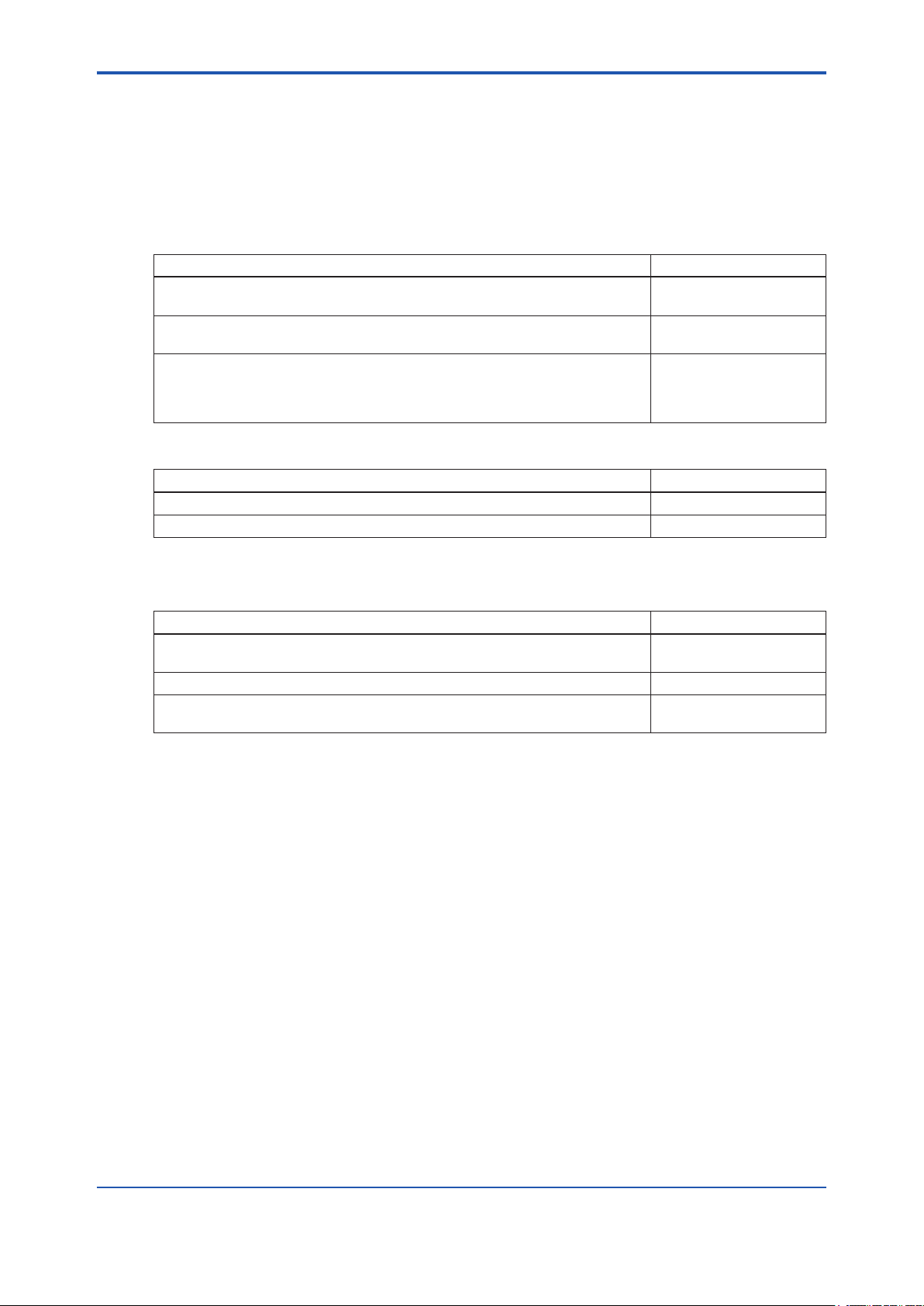
Table 1.1.1 User’s Manuals for magnetic owmeter ADMAG AXF
Title IM No.
AXF Magnetic Flowmeter, Integral Flowmeter/ Remote Flowtube
[Hardware Edition]
AXFA11G Magnetic Flowmeter, Remote Converter
[Hardware Edition/Software Edition]
AXFA14G/C Magnetic Flowmeter Remote Converter
[Hardware Edition/Software Edition]
AXF Magnetic Flowmeter Integral Flowmeter [Software Edition]
Table 1.1.2 User’s Manuals for external instruments
Title IM No.
Models AM012 Magnetic Flowmeter Calibrator FY2-XJAM012-40-2E
CA150 HANDY CAL IM CA150E
IM 01E20D01-01E
IM 01E20C01-01E
IM 01E20C02-01E
1-1
Refer to FieldMate User’s Manual when using AXF Verication Tool.
Table 1.1.3 User’s Manuals for FieldMate
Title IM No.
FieldMate
Versatile Device Management Wizard
FieldMate Operational Precaution IM 01R01A01-91E
FieldMate
Wizard Getting Started
IM 01R01A01-01E
IM 01R01A04-01E
IM 01R01A11-01EN
Page 6
<1 INTRODUCTION>
1.1 About This Manual
• This manual should be provided to the end user.
• Before using the AXF Verication Tool, read this manual thoroughly to comprehend its contents.
• The contents of this manual may be changed without prior notice.
• All rights are reserved. No part of this manual may be reproduced in any form without
Yokogawa’s written permission.
• Yokogawa makes no warranty of any kind with regard to this material, including, but not
limited to, implied warranties of merchantability and suitability for a particular purpose.
• All reasonable effort has been made to ensure the accuracy of the contents of this manual.
However, if any errors or omissions are found, please inform Yokogawa.
• Yokogawa assumes no responsibilities for this product except as stated in the warranty.
• Please note that this user’s manual may not be revised for any changes in specications,
construction changes or operating part changes that are not considered to affect function or
performance.
• If the customer or any third party is harmed by the use of this product, Yokogawa assumes
no responsibility for any such harm owing to any defects in the product which were not predictable, or for any indirect damages.
1-2
• This manual describes the operation of the AXF Verication Tool with FieldMate Advance.
For detail installation and operation of FieldMate and additional functions, please refer to the
FieldMate User’s Manual.
1.2 Safety and Modication Precautions
• The following general safety precautions must be observed during all phases of operation, service, and repair of this instrument. Failure to comply with these precautions or with
specic WARNINGS given elsewhere in this manual violates safety standards of design,
manufacture, and intended use of the instrument. Yokogawa assumes no liability for the
customer’s failure to comply with these requirements. If this instrument is used in a manner
not specied in this manual, the protection provided by this instrument may be impaired.
• Yokogawa will not be liable for malfunctions or damage resulting from any modication
made to this instrument by the customer.
• The following safety symbols are used in this user’s manual and on the instrument.
WARNING
A WARNING sign denotes a hazard. It calls attention to a procedure, practice, condition or the
like, which, if not correctly performed or adhered to, could result in injury or death of personnel
CAUTION
A CAUTION sign denotes a hazard. It calls attention to a procedure, practice, condition or the
like, which, if not correctly performed or adhered to, could result in damage to or destruction of
part or all of the product.
IM 01R01A11-01EN
Page 7

<1 INTRODUCTION>
IMPORTANT
An IMPORTANT sign denotes that attention is required to avoid damage to the instrument or
system failure.
NOTE
A NOTE sign denotes essential information for understanding operations and features.
1.3 Trademarks
All the brand names or product names of Yokogawa Electric used in this document are either
trademarks or registered trademarks of Yokogawa Electric Corporation.
All the brand names or product names of other companies mentioned in this document are either
trademarks or registered trademarks of their respective holders.
1-3
1.4 Software License Agreement
Refer to IM 01R01A01-01E Part A.
IM 01R01A11-01EN
Page 8

Blank Page
Page 9

<2 OUTILINE>
2 OUTILINE
AXF Verication Tool is a PC application software running in conjunction with FieldMate R2.05.00
or later.
Without having to remove the AXF magnetic owmeter from process line, its condition can be
veried by checking several items and this tool provides a certicate that the unit is operating in
accordance with YOKOGAWA standards. It is essentially an indication that the AXF is operating
to its standards and is useful in supporting plant maintenance practices. It differs from actual-ow
calibration at a manufacturing plant.
This tool stores verication data (*1) in a database (*2) in an organized manner, and can be used
to print a Verication Report that has not only the individual verication items (*3) result but also
the overall status of “passed” or “failed”. It is thus useful for device maintenance management.
*1: Verication data means the data saved by the user.
*2: Database means a collection of verication data saved in Device Maintenance Information.
*3: For the verication items, refer to 2.2.
2-1
IM 01R01A11-01EN
Page 10
<2 OUTILINE>
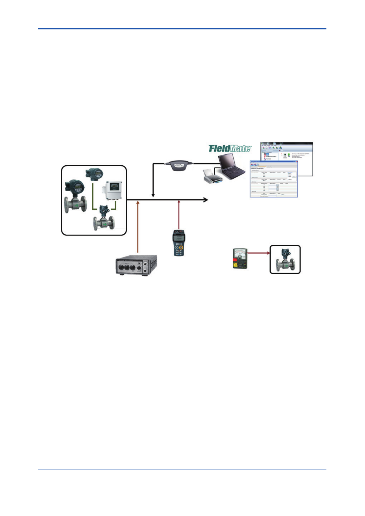
2.1 Conguration
The following equipment is required to use Verication Tool ver. 1.01.00;
• YOKOGAWA magnetic owmeter AXF with HART Communication (AXF Output Signal and
Communication sufx code: -E).
• PC (*1) and Printer
• Magnetic Flowmeter Calibrator AM012 (Only for Enhanced VF (*2), Optional)
• Handy Calibrator CA150 or equivalent (Only for Enhanced VF (*2), Optional)
• Insulation Checker (Only for Enhanced VF (*2), Optional)
*1: Regarding the PC environment, refer to IM 01R01A01-01E Part B,C.
*2: VF stands for “Verication”.
- Circuit Check
- Device Status Check
- Physical Appearance Check
USB FieldMate Modem
2-2
Magnetic Flowmeter
AXF
MA012
Calibrator
(Optional)
- Converter Check
Figure 2.1.1 Congurations
Output Signal
4-20mA or pulse
CA150
Handy Calibrator
(Multi-meter)
(Optional)
- Current Output Check
- Pulse Output Check
Printer
PC
Insulation checker
(Optional)
- Insulation Resistance
Check
Magnetic
Flowmeter
AXF
F020301.ai
IM 01R01A11-01EN
Page 11

<2 OUTILINE>
2.2 Verication Item
This Verication Tool has 2 modes, which can be run separately.
1. Standard Verication (Standard VF)
• This mode veries the condition of the AXF without difculty by checking its internal parameters. No external instruments are required.
• Some items are run only when FieldMate is in “online (*1)” mode.
2. Enhanced Verication (Enhanced VF) [Optional]
• This mode provides a more reliable verication by performing a detailed overview equivalent
to SERVICE.
• This mode is optional. If only this mode is completed, “Overall Status” is left blank.
• This mode veries AXF by using external instruments, such as Magnetic Flowmeter Calibrator AM012, Handy Calibrator CA150, and so on.
• Even when FieldMate is in “ofine (*2)” mode, this mode can be run; in this case, some settings must be made manually.
There are only 2 possible combinations:
1. Standard VF
2-3
2. Standard VF + Enhanced VF
Table 2.2.1 Verication Items
Mode Verication Item Description
Standard VF Circuit (*3)
Magnetic Circuit Checks the Magnetic Circuit.
Excitation Circuit Checks the Excitation Circuit.
Calculation Circuit Checks the Calculation Circuit.
Device Status (*3)
Alarm Check Checks occurring Alarms.
Alarm History Checks historical Alarms.
Physical Appearance
Flowtube Checks the Flowtube appearance.
Converter Checks the Converter appearance.
Enhanced VF Current Output (*4) Checks the Current Output.
Pulse Output (*4) Checks the Pulse Output.
Converter (*4) Checks the Converter Accuracy.
Insulation Resistance
Coil
Signal (Electrode)
Checks the Excitation Coil.
(Remote Flowtube Only)
Checks the Insulation Resistance.
(Remote Flowtube Only)
*1: Online: The status in which the software communicates with a device.
*2: Ofine: The status in which the software does not communicate with a device.
The communication status between FieldMate and AXF can be conrmed on the FieldMate window.
*3: These items are checked only when Verication Tool is in “online” mode.
*4: When Verication Tool is in “ofine” mode, manual setting is necessary.
IM 01R01A11-01EN
Page 12
<2 OUTILINE>
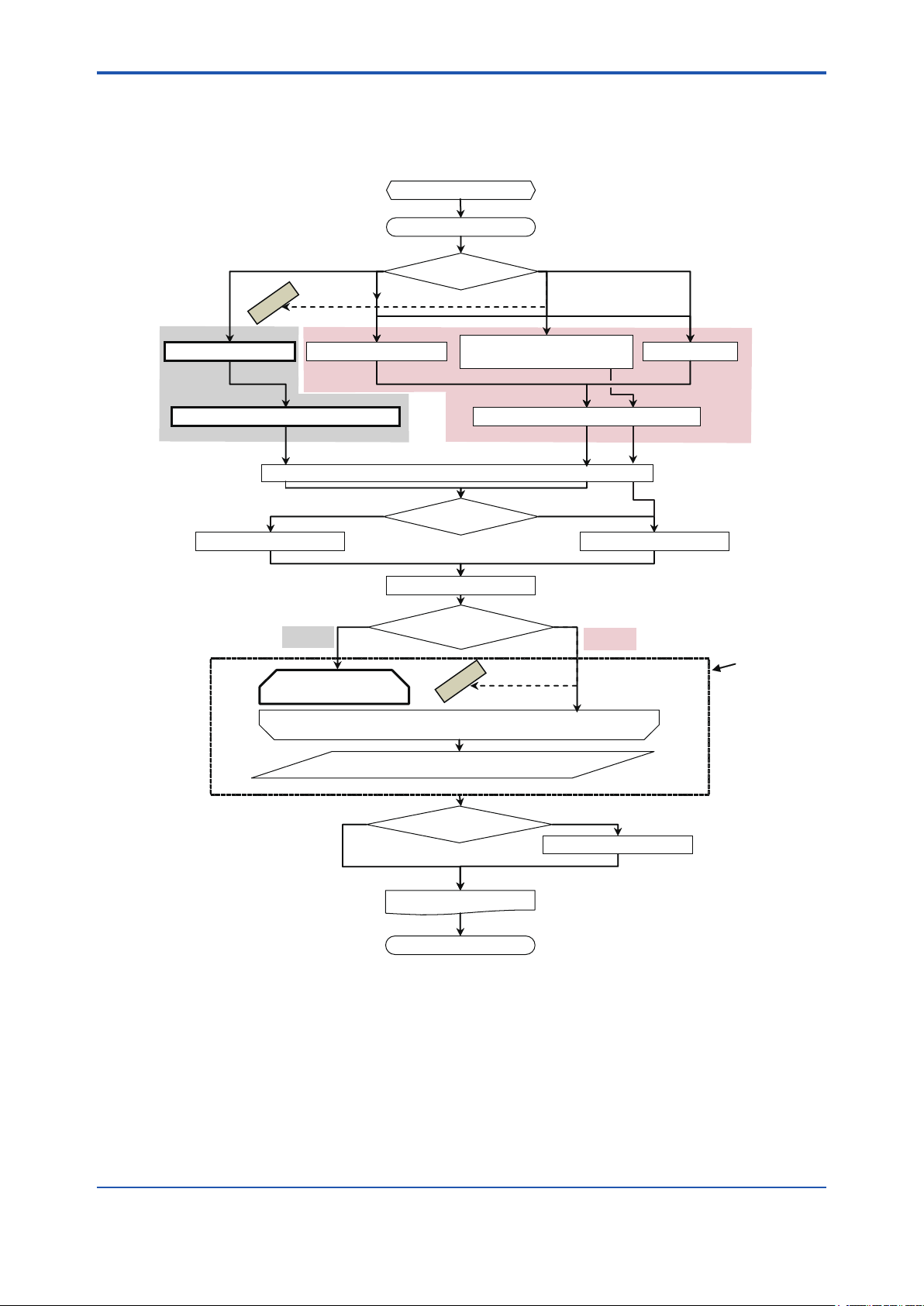
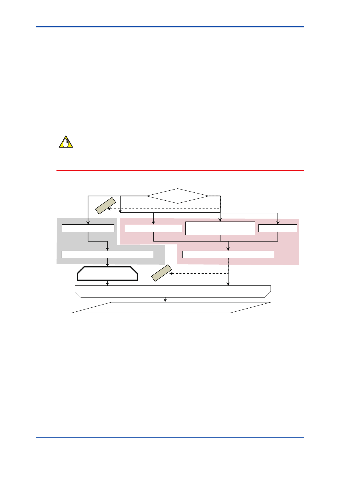
2.3 Operation Procedure
Figure 2.3.1 summarizes operation procedure.
To complete “Standard VF”, start-up Verication Tool from “Segment Viewer”. See 4.1.
1 to 3 PREPARATION
4 START-UP
2-4
Online Offline
IMPOSSIBLE
4.1 Segment Viewer 4.2 Device Navigator
No. New data Yes
5.3 General Information
Online
6.2 Standard VF
(Mandatory)
FieldMate and AXF
5 LAUNCHING
Use the existing data?
6.1 Main Screen
Verification Tool and AXF
6.3 Enhanced VF
4.3 Verification Data
in “Device Maintenance Info”
Verification Tool and AXF: OfflineVerification Tool and AXF: Online
IMPOSSIBLE
(Optional)
4.4 History
5.2 Load
Offline
Verification
Operation
No Yes
Figure 2.3.1 Operation Procedure
6.4 Result
Save the verification data ?
6.1.3 Print out
8 TERMINATION
6.1.2 Save
F020301.ai
IM 01R01A11-01EN
Page 13

<3 PREPARATION>
3 PREPARATION
3-1
WARNING
• Before running the Verication Tool, loop should be set to manual mode in the host system.
• The following applications may cause inadequate results:
- Signicantly-low ow rate
- Slurry liquid
- Stray current
• When “unexpected issue (*1)” occurs while running Verication Tool, follow “8.2 Unexpected Termination” and “9 Communication Error”
*1: “Unexpected issue” means disconnection between AXF and PC:
• Physical disconnection between AXF and PC
• Forced shutdown of PC
• Unforeseen AXF power-off
IM 01R01A11-01EN
Page 14
<3 PREPARATION>
3.1 Package and Installation
Regarding the packaging and installation procedure, refer to IM 01R01A01-01E Part B.
3.2 AXF Write Protect Cancellation
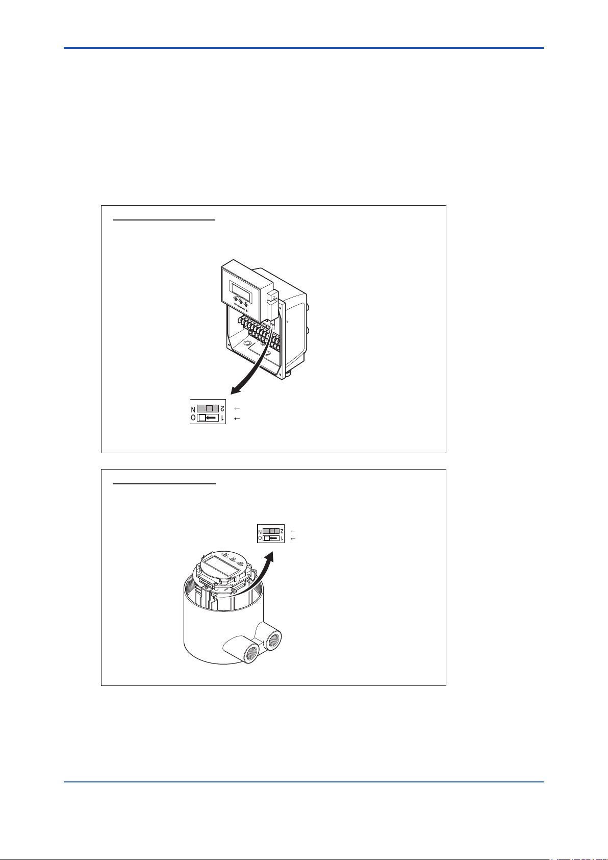
3.2.1 Before Verication
1) AXF parameters are changed during the verication process. Cancel the write protect
switch.
Hardware switch off
Set the "Write Protect Switch" to "Enable" before this verification.
Return the switch to the original position after this verification is
complete.
3-2
Switch 1
Switch 2
Enable Protect
(A) AXFA11
2 Burnout setting switch
1 Write protect setting switch
F030201-A.ai
Hardware switch off
Set the "Write Protect Switch" to "Enable" before this verification.
Return the switch to the original position after this verification is
complete.
Switch 1
Switch 2
Enable Protect
(B) AXFA14 or AXF Integral Flowmeter
Figure 3.2.1 Write Protect Cancellation
2 Burnout setting switch
Write protect setting switch
1
F030201-B.ai
2) After the verication is complete, return the switch to the original position.
IM 01R01A11-01EN
Page 15
<3 PREPARATION>
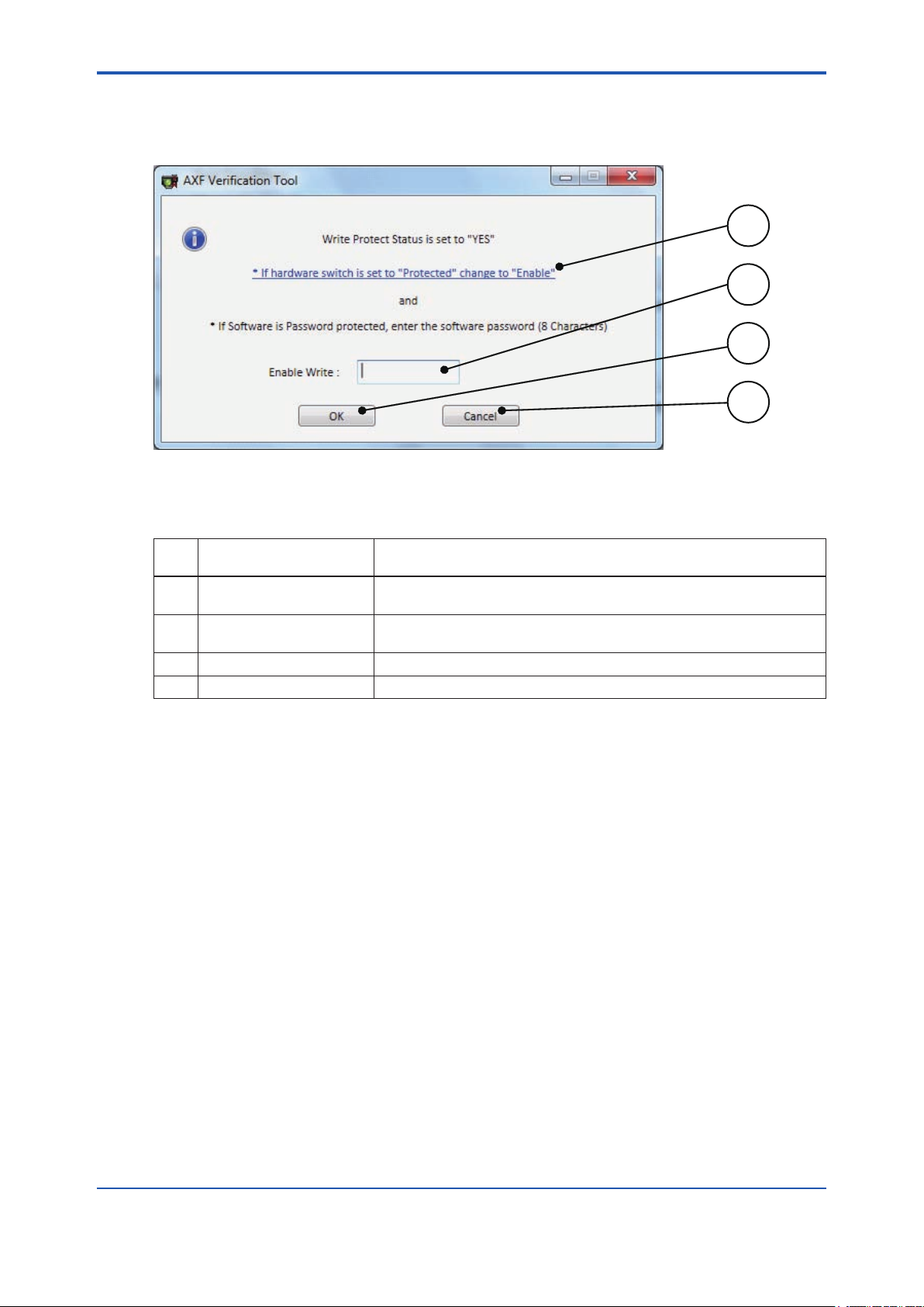
3.2.2 During Verication
1) If the AXF write protect function is set to “Protect” during the verication, Figure 3.2.2 will be
displayed.
Figure 3.2.2 “Write Protect Cancellation” Dialog
3-3
1
2
3
4
F030202.ai
Table 3.2.1 “Write Protect Cancellation” Dialog
Item
No.
1 ‘If hardware….’
2 Enable Write
3 OK Runs the software protection cancellation.
4 Cancel Cancels ‘Write Protect cancellation’
Item Name Description
Shows the gure of hardware switch. See Figure 3.2.1.
Click the text.
Cancels the software protection of the device.
Enter the password.
2) Set the “Write Protect Switch” to “Enable” .
Then, enter the password in (2) and click “OK (3)” in Figure 3.2.2.
3) Return the switch to the original position after this verication is complete.
IM 01R01A11-01EN
Page 16

Blank Page
Page 17
<4 START-UP FROM FieldMate>
4 START-UP FROM FieldMate
Verication Tool can be started by the following:
■ From “Segment Viewer” (FieldMate is online to AXF), see 4.1.
■ From “Device Navigator”, see 4.2.
■ From “Verication Data” in “Device Maintenance Info”, see 4.3.
■ From “History”, see 4.4.
Select the start-up procedure depending on the items to be veried and connection status be-
tween FieldMate and AXF.
NOTE
• To run Verication Tool in “online” mode, start the Verication Tool from “Segment Viewer”.
• To complete Standard VF, start Verication Tool from “Segment Viewer”.
4-1
Online
IMPOSSIBLE
4.1 Segment Viewer
6.2 Standard VF
(Mandatory)
Figure 4.1.1 “Start-up” Procedure
FieldMate and AXF
4.2 Device Navigator
IMPOSSIBLE
6.3 Enhanced VF
(Optional)
6.4 Result
Offline
4.3 Verification Data
in “Device Maintenance Info”
Verification Tool and AXF: OfflineVerification Tool and AXF: Online
4.4 History
F040101.ai
IM 01R01A11-01EN
Page 18
<4 START-UP FROM FieldMate>
4-2
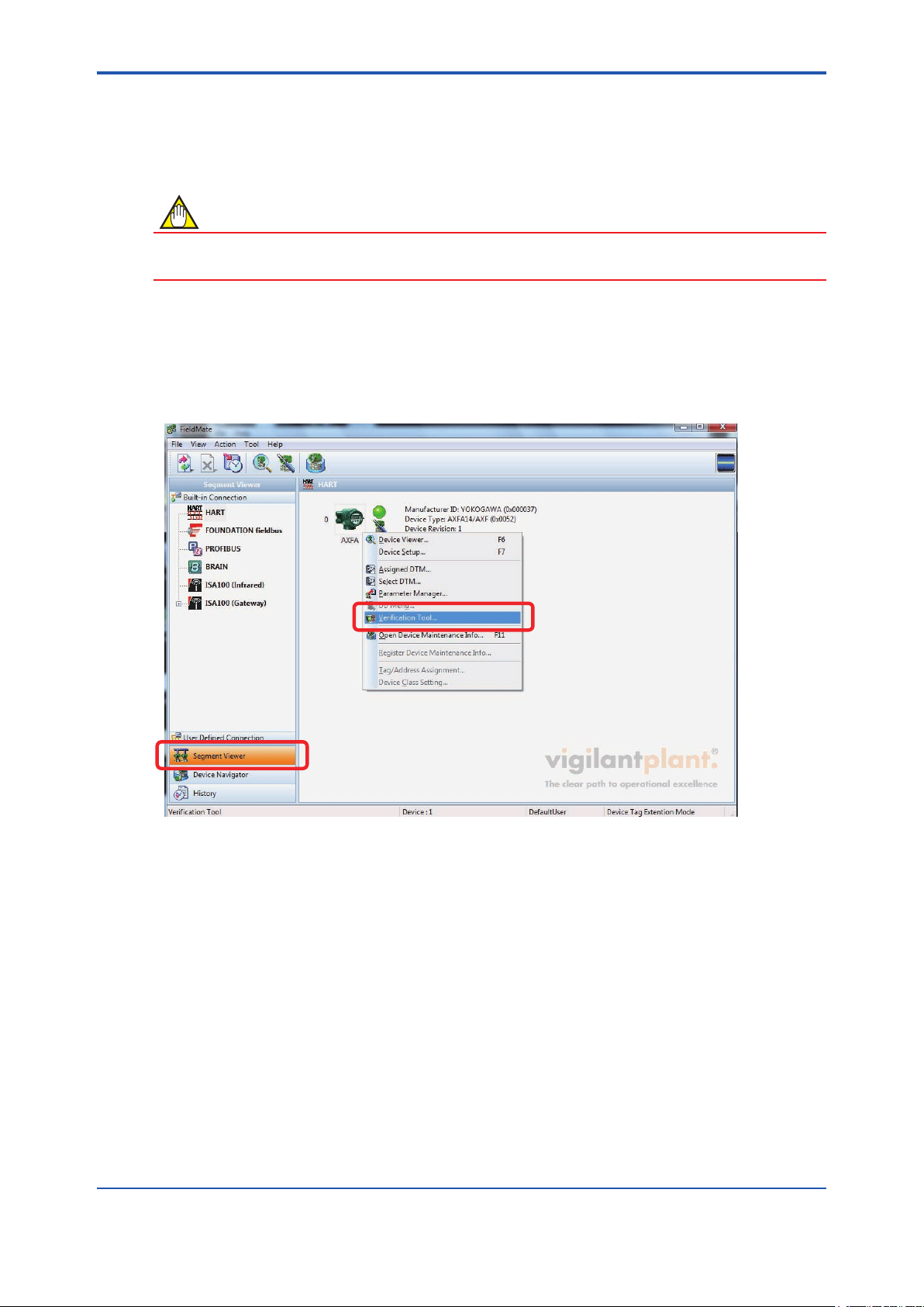
4.1 From “Segment Viewer” (AXF is reading in “online” mode in FieldMate)
NOTE
Set the device address to 0. Verication Tool can be started only when the device address is set
to 0. For details on how to set the device address, refer to 9.2.
From “Segment Viewer”, “Verication Tool” can be started by either method (A) or (B).
(A) By right-clicking
Right-click on the target (AXF) icon displayed at “Segment Viewer”, and select “Verication Tool”.
Figure 4.1.2 Start-up from “Segment Viewer” by Right-clicking
F040102.ai
IM 01R01A11-01EN
Page 19
<4 START-UP FROM FieldMate>
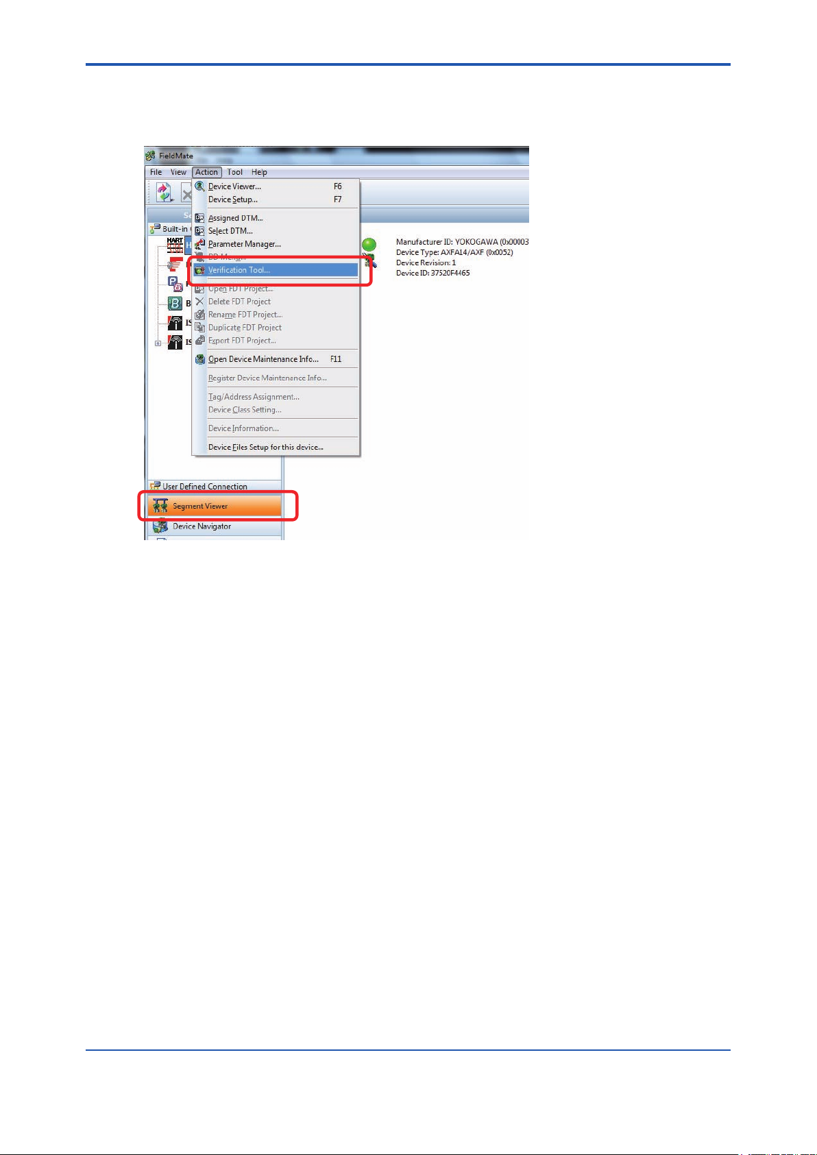
(B) By selecting menu “Action”
Select the target (AXF) icon displayed at “Segment Viewer”, and in the “FieldMate” menu bar,
select “Action - Verication Tool”.
4-3
F040103.ai
Figure 4.1.3 Start-up from “Segment Viewer” by Selecting the “Action” Menu
IM 01R01A11-01EN
Page 20
<4 START-UP FROM FieldMate>
4.2 From “Device Navigator”
NOTE
When Verication Tool is started from “Device Navigator”, it will be in “ofine” mode even if the
AXF is in “online” mode in FieldMate.
From “Device Navigator”, “Verication Tool” can be started by either method (A) or (B).
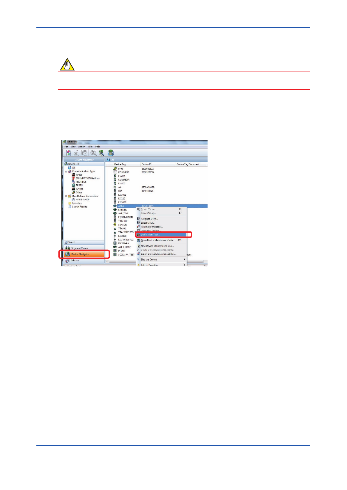
(A) By right-clicking
Right-click on the target (AXF) icon displayed at “Device Navigator”, and select “Verication Tool”.
4-4
F040201.ai
Figure 4.2.1 Start-up from “Device Navigator” by Right-clicking
IM 01R01A11-01EN
Page 21
<4 START-UP FROM FieldMate>
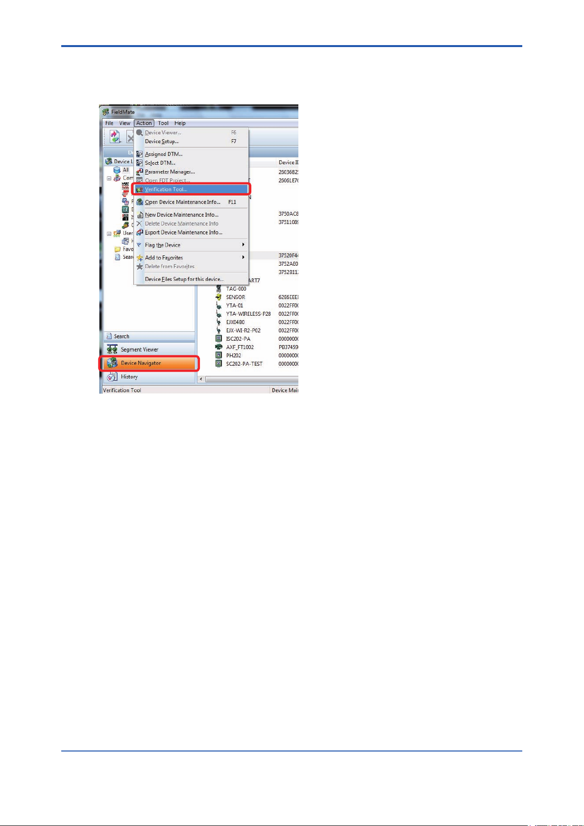
(B) By selecting menu “Action”
Select the target (AXF) icon displayed at “Device Navigator”, and in the “FieldMate” menu bar,
select “Action - Verication Tool”.
4-5
F040202.ai
Figure 4.2.2 Start-up from “Device Navigator” by Selecting the “Action” Menu
IM 01R01A11-01EN
Page 22
<4 START-UP FROM FieldMate>
4.3 From “Verication Data” in “Device
Maintenance Info”
NOTE
When Verication Tool is started from “Device Maintenance Info”, it will be in “ofine” mode even
if the AXF is in “online” mode in FieldMate.
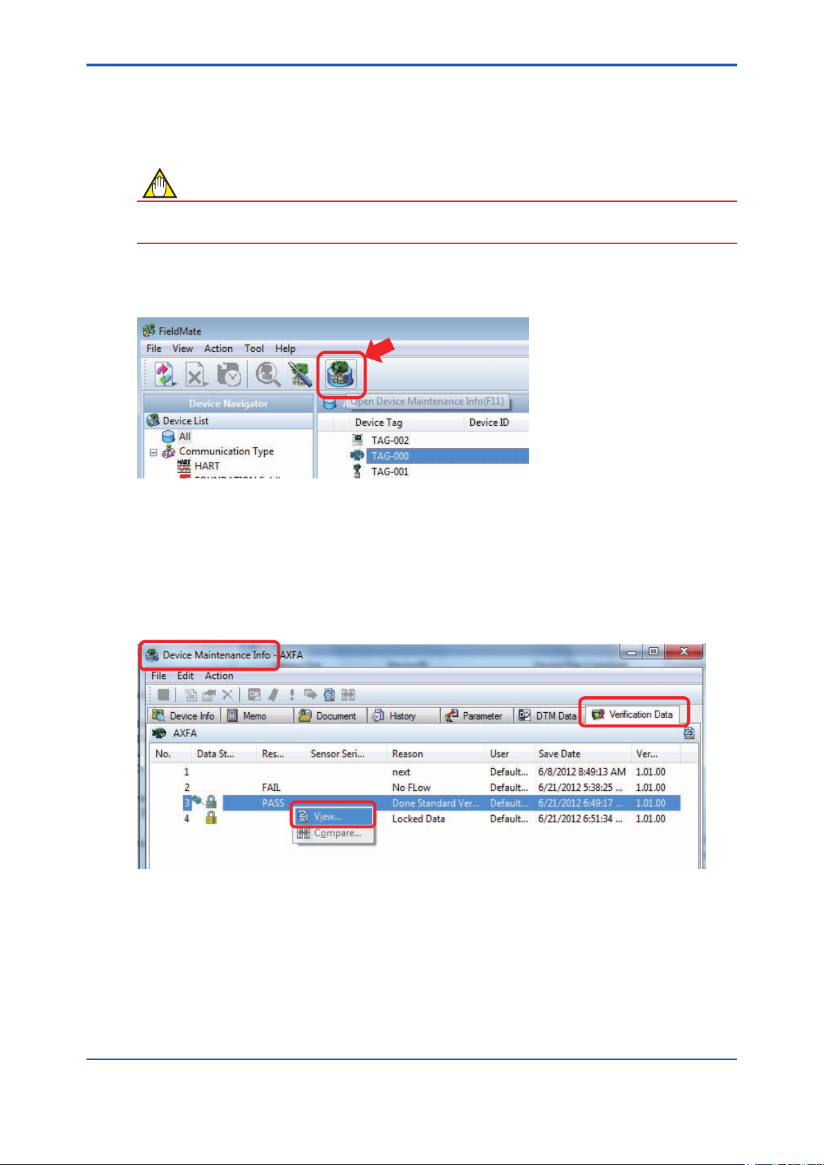
From the “Verication Data” tab in “Device Maintenance Info”, “Verication Tool” can be started
by either method (A) or (B). Select the target (AXF) icon and click the “Open Device Maintenance
Info” icon. The “Device Maintenance Info” screen appeares.
4-6
Figure 4.3.1 “Device Maintenance Info” Icon
(A) By right-clicking
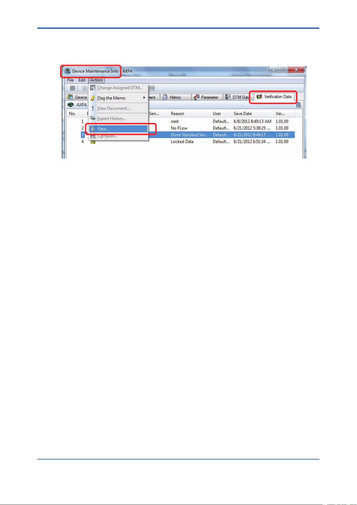
Select the “Verication Data” tab on the “Device Maintenance Info” screen. Right-click on the
verication data listed on the “Verication Data” tab under “Device Maintenance Info, and select
“View”. Verication Tool is started up and the selected verication data is loaded.
Figure 4.3.2 Start-up from “Verication Data” in “Device Maintenance Info” by Right-clicking
F040301.ai
F040302.ai
IM 01R01A11-01EN
Page 23
<4 START-UP FROM FieldMate>
(B) By selecting menu “Action”
In the “Device Maintenance Info” menu bar, select “Action”-“View”. Verication Tool is started up
and the selected verication data is loaded.
Figure 4.3.3 Start-up from “Verication Data” in “Device Maintenance Info” by Selecting the “Action”
Menu
4-7
F040303.ai
IM 01R01A11-01EN
Page 24
<4 START-UP FROM FieldMate>
4.4 From “History”
NOTE
When Verication Tool is started from “History”, it will be in “ofine” mode even if the AXF is in
“online” mode in FieldMate.
From “History”, “Verication Tool” can be started by either method (A) or (B).
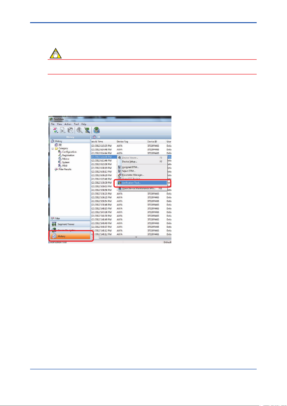
(A) By right-clicking
Right-click on the target device (AXF) listed in “History”, and select “Verication Tool”.
4-8
Figure 4.4.1 Start-up from “History” by Right-clicking
F040401.ai
IM 01R01A11-01EN
Page 25
<4 START-UP FROM FieldMate>
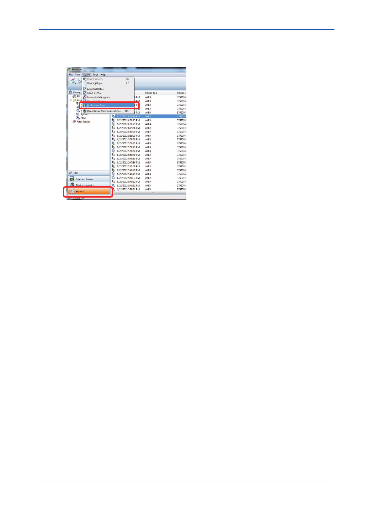
(B) By selecting menu “Action”
Select the target (AXF) listed in “Device Maintenance Info”, and in the “FieldMate” menu bar,
select “Action”-“Verication Tool”.
F040402.ai
Figure 4.4.2 Start-up from “History” by Selecting the “Action” Menu
4-9
IM 01R01A11-01EN
Page 26

Blank Page
Page 27

<5 LAUNCHING>
5 LAUNCHING
When Verication Tool is launched, Figure 5.1.1 is displayed automatically.
F050101.ai
Figure 5.1.1 Splash Screen
Select the verication data to be used for the verication:
1. Creating new verication data: see 5.1.
5-1
2. Loading existing verication data: see 5.2.
3. After unexpected termination: see 5.3
IM 01R01A11-01EN
Page 28

<5 LAUNCHING>
5.1 Creating New Verication Data
1) After the “Splash Screen”,
1)-1 When there is no existing verication data in the database:
The splash screen is closed automatically, and then Figure 5.1.3 is displayed.
1)-2 When there is existing verication data in the database:
1)-2-1 The splash screen is closed automatically, and then Figure 5.1.2 is displayed.
1
2
F050102.ai
Figure 5.1.2 “Conrmation” Dialog
5-2
Table 5.1.1 “Conrmation” Dialog
Item
No.
1 Load
2 Cancel
Item Name Description
Loads the verication data from the database. See 5.2.
To load the verication data, click “Load”.
Creates new verication data and shows Figure 5.1.3.
To create new verication data, click “Cancel”.
1)-2-2 Click “Cancel (2)”.
If “Load (1)” is selected by accident, Figure 5.2.1 is displayed. Click “Cancel (3)” in
Figure 5.2.1.
IM 01R01A11-01EN
Page 29

<5 LAUNCHING>
2) “General Information” is displayed. See Figure 5.1.3.
Enter each eld and click “Next (8)”. Figure 6.1.1 is displayed automatically.
1
2
3
4
5
6
7
5-3
8
F050103.ai
Figure 5.1.3 “General Information” Dialog
Table 5.1.2 “General Information” Dialog
Item
No.
1 User Name (*)
2 Location. (*) Enter the user location.
3 Veried by (*) Enter the name of the person to operate the verication.
4 Tag (Converter)
5 Tag (Flowtube) Enter the tag number of the owtube.
6 Serial No. (Converter) Enter the serial number of the converter.
7 Serial No. (Flowtube) Enter the serial number of the owtube.
8 Next
*: Mandatory eld
Item Name Description
Enter the user name.
The user name of FieldMate is displayed by default. This eld can be
edited.
Enter the tag number of the converter. The value of HART parameter
“Tag” is displayed by default. This eld can be edited.
Even if a different value is input from the HART parameter, the HART
parameter is not overwritten.
Moves to “Main Screen”. See Chapter 6.
Is enabled only after the mandatory elds have been lled in.
Click “Next” to move to “Main Screen”.
IM 01R01A11-01EN
Page 30

<5 LAUNCHING>
5.2 Loading Existing Verication Data
NOTE
In terms of keeping the integrity of the data, loaded verication data cannot be copied, nor can it
be saved under a different name. Loaded verication data can only be overwritten by new saved
data, except for “Locked data” which cannot be modied.
1) After the “Splash screen” is closed automatically, Figure 5.1.2 is displayed.
2) Click “Load (1)” in Figure 5.1.2. Figure 5.2.1 is displayed.
3) Select the preferred data from “Data list (1)” and click “OK (2)” in Figure 5.2.1.
5-4
1
2
3
F050201.ai
Figure 5.2.1 “Select Verication Data” Dialog
Table 5.2.1 “Select Verication Data” Dialog
Item
No.
1 Data list
2 OK
3 Cancel
2) After loading, Figure 5.2.2 is displayed automatically. Click “OK”. “Main Screen” is dis-
played. See Chapter 6.
Item Name Description
Shows the verication data in the database.
For the meaning of the icon in the “Data Status”, see Chapter 7.
Loads the verication data.
To use the verication data in the database, select the preferred one
among “Data list” and click “OK”. Figure 5.2.2 is displayed.
Creates new verication data and shows Figure 5.1.3. See 5.1.
To create the new verication data, click “Cancel”.
F050202.ai
Figure 5.2.2 “Verication Data Loaded” Dialog
IM 01R01A11-01EN
Page 31

<5 LAUNCHING>
5.3 After Unexpected Termination
In case of launching after an unexpected termination of the program, see 8.2.
5-5
IM 01R01A11-01EN
Page 32

Blank Page
Page 33

<6 OPERATION>
6 OPERATION
This chapter describes how to use Verication Tool.
For details of the verication procedure, see 6.2 and 6.3.
NOTE
• Be sure to run Standard VF.
• “Overall Status” in “Result” is carried out only when “Standard VF” is complete. When
“Standard VF” is not complete, “Overall Status” is left blank.
• “Result sheet” can be printed even when “Standard VF” is not complete.
6-1
IM 01R01A11-01EN
Page 34

<6 OPERATION>
6.1 Main Screen
This screen performs the following actions:
■ Loads the verication data. See 6.1.1.
■ Saves the verication data. See 6.1.2.
■ Prints the result sheet. See 6.1.3.
■ Displays the “Standard” VF screen. See 6.2.
■ Displays the“Enhanced” VF screen. See 6.3.
■ Displays the “Result” screen. See 6.4.
4
1 2 3
6-2
Figure 6.1.1 Main Screen
Table 6.1.1 Main Screen
Item
No.
1 Load
2 Save
3 Print
4 Menu bar Shows the “File” and “Help” menus. See 6.1.4.
5 Standard Selects Standard VF mode. See 6.2.
6 Enhanced Selects Enhanced VF mode. See 6.3.
7 Result Displays the result sheet image. See 6.4.
Item Name Description
Loads the verication data from the database. See 6.1.1.
To load the verication data, click “Load”.
Saves the current data to the database. See 6.1.2.
To save the current data, click “Save”.
Prints out the result. See 6.1.3.
To print the verication result, click “Print”.
7
6
5
F060101.ai
IM 01R01A11-01EN
Page 35

<6 OPERATION>
6.1.1 Load
1) Click the “Load” icon.
F060102.ai
Figure 6.1.2 “Load” Icon
2) After clicking the “Load” icon, Figure 6.1.3 is displayed. Select the preferred data from “Data
list (1)”, then click “OK (2)”.
6-3
1
Figure 6.1.3 “Select Veri cation Data” Dialog
Table 6.1.2 “Select Veri cation Data” Dialog
Item
No.
1 Data list
2 OK
3 Cancel
Item Name Description
Shows the veri cation data in the database.
Select the preferred data.
Performs data loading.
To load the veri cation data from the database, click “OK”.
Cancels loading the veri cation data and returns to “Main Screen”. See
6.1.
4) After loading, Figure 6.1.4 is displayed automatically. Click “OK”.
2
3
F060103.ai
F060104.ai
Figure 6.1.4 “Veri cation Data Loaded” Dialog
IM 01R01A11-01EN
Page 36

<6 OPERATION>
6.1.2 Save
By clicking the “Save” icon, the veri cation data is saved to the database.
After clicking “Save”, the screen changes as follows:
• When “No Flow + Flow (*1)” is not complete, see (A).
• When “No Flow + Flow” is complete, see (B).
*1: “No Flow + Flow”;
“Circuit” check and “Device Status” check for both “No Flow” and “Flow” conditions. Refer to 6.2.1.
F060105.ai
Figure 6.1.5 “Save” Icon
6-4
(A) When “No Flow + Flow” is not complete:
1) After clicking the “Save” icon, Figure 6.1.6 is displayed.
1 2 3
Figure 6.1.6 “Saving Data When “No Flow + Flow” Uncompleted” Dialog
Table 6.1.3 “Saving Data When “No Flow + Flow” Uncompleted” Dialog
Item
No.
1 Reason
2 Saved as Installation Data.
3 Saved as Locked Data.
4 OK Saves the data.
5 Cancel Cancels saving the data and returns to “Main Screen”. See 6.1.
Item Name Description
Shows the reason or comment. It can be used as a marker when loading
veri cation data is selected. Refer to Figure 6.1.3.
Enter preferred text.
(Optional eld)
Saves the data as “Installation Data”. See 7.1.
This eld is disabled until “No Flow + Flow” is complete.
Saves the data as “Locked Data”. See 7.2.
To save the data as read-only, check the box.
(Always valid)
4
5
F060106.ai
IM 01R01A11-01EN
Page 37

<6 OPERATION>
2) Save the data as “Read-only” or “Editable”.
2)-1 To save the verication data as read-only:
Click “OK” after checking the “Saved as Locked Data” box in Figure 6.1.6.
Figure 6.1.7 is displayed. Click “Yes” in Figure 6.1.7.
1
2
F060107.ai
Figure 6.1.7 “Conrm Locked Data” Dialog
Table 6.1.4 “Conrm Locked Data” Dialog
6-5
Item
No.
1 Yes Saves verication data to the database as read-only.
2 No Cancels saving the data and returns to Figure 6.1.6.
Item Name Description
2)-2 To save the verication data as editable:
Click “OK” without checking the “Saved as Locked Data” box in Figure 6.1.6.
No dialogs appear.
3) Figure 6.1.8 is displayed automatically. Click “OK”.
F060108.ai
Figure 6.1.8 “Saving Completed” Dialog
IM 01R01A11-01EN
Page 38

<6 OPERATION>
(B) When “No Flow + Flow” is complete:
1) After clicking the “Save” icon, Figure 6.1.9 is displayed.
1 2 3
4
5
F060109.ai
Figure 6.1.9 “Saving Data When “No Flow + Flow” Completed” Dialog
Table 6.1.5 “Saving Data When “No Flow + Flow” Completed” Dialog
6-6
Item
No.
1 Reason
Saved as Installation Data.
2
(*1)
Saved as Locked Data.
3
(*1)
4 OK Saves the data.
5 Cancel Cancels saving the data and shows “Main Screen”. See 6.1.
*1: These items can be selected at the same time.
Item Name Description
Shows the reason or comment. It can be used as a marker when the loading verication data is selected. Refer to Figure 6.1.3.
Enter preferred text.
(Optional eld)
Saves the data as installation data. See 7.1.
To save the data as installation data, check the box.
Saves the data as locked data. See 7.2.
To save the data as locked data, check the box.
2) Select the preferred one accordingly.
2)-1 To save the verication data as “Installation Data”:
Click “OK” after checking the “Saved as Installation Data” box.
If there is no existing installation data in the database, no dialogs appear.
If there is existing installation data in the database, Figure 6.1.10 is displayed.
Click “Yes” in Figure 6.1.10.
1
Figure 6.1.10 “Conrm Replacing Data” Dialog
2
F060110.ai
IM 01R01A11-01EN
Page 39

<6 OPERATION>
Table 6.1.6 “Conrm Replacing Data” Dialog
6-7
Item
No.
1 Yes Replace the data.
2 No Cancels replacing the data and returns to Figure 6.1.9.
Item Name Description
2)-2 To save the verication data as read-only:
Click “OK” after checking the “Saved as Locked Data” box in Figure 6.1.9. Figure 6.1.11 is
displayed.
Click “Yes” in Figure 6.1.11.
1
2
F060111.ai
Figure 6.1.11 “Conrm Locked Data” Dialog
Table 6.1.7 “Conrm Locked Data” Dialog
Item
No.
1 Yes Saves the data as locked data.
2 No Cancels saving the data and returns to Figure 6.1.9.
Item Name Description
2)-3 To save the verication data as editable and non-installation data:
Click “OK” without checking any boxes in Figure 6.1.9.
No dialogs appear.
3) Figure 6.1.12 is displayed automatically. Click “OK”.
F060112.ai
Figure 6.1.12 “Saving Completed” Dialog
IM 01R01A11-01EN
Page 40

<6 OPERATION>
6.1.3 Print out
To print the result sheet, click the “Print” icon. Figure 6.1.14 is displayed.
F060113.ai
Figure 6.1.13 “Print” Icon
6-8
F060114.ai
Figure 6.1.14 Example of “Print” Dialog
The printed image is the same as the “Result” tab in “Main Screen”. See 6.4.
The recommended paper size is A4 or letter size.
• If the paper size is smaller than the recommended one, the printed size is reduced to t the
paper.
• If the paper size is bigger than the recommended one, the printed size will be the recommended one.
IM 01R01A11-01EN
Page 41

<6 OPERATION>
6.1.4 Menu bar
There are “File” and “Help” in the menu bar.
(A) File
Select the preferred menu.
1
2
3
4
F060115.ai
Figure 6.1.15 Menu bar
Table 6.1.8 Menu bar
6-9
Item
No.
Load from
1
Database
2 Save to Database Same as “Save” in Table 6.1.1. See 6.1.2.
3 Print Same as “Print” in Table 6.1.1. See 6.1.3.
4 Exit Terminates the Verication Tool. See 8.1.
Item Name Description
Same as “Load” in Table 6.1.1. See 6.1.1.
IM 01R01A11-01EN
Page 42

<6 OPERATION>
(B) Help
Upon selecting “About AXF Verication Tool…” in the “Help” menu, Figure 6.1.17 is displayed.
1
F060116.ai
Figure 6.1.16 Help Menu
Table 6.1.9 Help Menu
6-10
Item
No.
About AXF Verication
1
Tool…
Figure 6.1.17 Example of Version Information
Item Name Description
Shows the version of Verication Tool. See Figure 6.1.17.
F060117.ai
IM 01R01A11-01EN
Page 43

<6 OPERATION>
6.2 Standard VF
■ This mode veries the condition of the AXF without difculty, by checking its internal parameters. No external instruments are requied.
■ This mode is mandatory.
■ “Circuit” check and “Device Status” check are run only when Verication Tool is in “online”
mode.
■ Each item can be run separately.
6-11
1
2
Figure 6.2.1 “Standard VF” Screen
Table 6.2.1 “Standard VF” Screen
Item
No.
1 Circuit Checks the status of device circuits. See 6.2.1.
2 Device Status Checks the alarm in AXF parameters. See 6.2.1.
3 Physical Appearance Checks the physical appearance. See 6.2.2.
Item Name Description
3
F060201.ai
IM 01R01A11-01EN
Page 44

<6 OPERATION>
6.2.1 “Circuit” check and “Device Status” check
(Verication Tool is in “online” mode)
CAUTION
• “Circuit” check and “Device Status” check temporarily change the parameters of AXF. In
case of unexpected termination, follow 8.2.
• The AXF owtube should be completely lled with uid, otherwise the results may be
inadequate.
• These items are run only when Verication Tool is in “online” mode.
• These items are veried for 2 types. Each condition check can be run separately.
(A) “No Flow” condition:
Veries the condition of the AXF by checking;
- Circuits including the excitation circuit and the magnetic circuit inside the owtube when
the uid velocity is completely zero.
- The present and past history of alarms.
6-12
(B) “Flow” condition:
Veries the condition of the AXF by checking;
- Circuits including the excitation circuit and the operation circuit which calculates the ow
velocity when the uid velocity is sufcient.
- The present and past history of alarms.
• There are 3 combinations:
(1) No Flow
(2) Flow
(3) Flow + No Flow
• The check items of the “Circuit” check depend on the case as follows:
• Nominal size of the unit.
• With or without the optional code ELC (DC Noise Cut Circuit).
• Test condition type; “Flow” or “No Flow”.
For details, see Table 6.2.2.
IM 01R01A11-01EN
Page 45

<6 OPERATION>
1
6-13
2
3
4
5
6
7
Figure 6.2.2 “Circuit and Device Status” Screen
Table 6.2.2 “Circuit and Device Status” Screen
(1) Nominal size is 400mm or smaller, without optional code ELC
Item
No.
1
2 Test Condition
3
4
5
6
7
Item Name Description
No Flow
Flow
Circuit
Device
Status
Magnetic
Circuit
Excitation
Circuit
Calculation
Circuit
Alarm
Check
Alarm
History
Shows test condition.
Select the test condition
Shows operated test condition.
“No Flow” or ” Flow” or ” No Flow
+ Flow”
See Figure 6.2.13.
Shows the result of the
Magnetic Circuit check.
“Magnetic Circuit” means checking the magnetic circuit inside the
owtube.
Shows the result of the
Excitation Circuit check.
“Excitation Circuit” means checking the excitation circuit by the
excitation current measurement.
Shows the result of the
Calculation Circuit check.
“Calculation Circuit” means checking the operation circuit which
calculates the ow velocity.
Shows the result of the Alarm
Check.
“Alarm Check” means checking
the occurrence of alarms.
Shows the result of Alarm History
Check.
“Alarm History Check” means
checking the history of alarms that
occurred.
F060202.ai
Check is [possible/ not available]
No Flow Flow
Possible
Possible Possible Possible
Not Avail-
able
[Shows :N/A]
Possible Possible Possible
Possible Possible Possible
Not Avail-
able
[Shows: N/A]
Possible Possible
No Flow +
Flow
Possible
IM 01R01A11-01EN
Page 46

<6 OPERATION>
(2) Nominal size is over 400mm, without optional code ELC (DC Noise Cut Circuit)
6-14
Item
No.
1
2 Test Condition Same as Table 6.2.2 (1) “No.2”
3
4
5
6
7
(3) With optional code ELC (DC Noise Cut Circuit)
Item
No.
1
2 Test Condition Same as Table 6.2.2 (1) “No.2”
3
4
5
6
7
Item Name Description
No Flow
Flow
Magnetic
Circuit
Circuit
Device
Status
No Flow
Flow
Circuit
Device
Status
Excitation
Circuit
Calculation
Circuit
Alarm
Check
Alarm
History
Item Name Description
Magnetic
Circuit
Excitation
Circuit
Calculation
Circuit
Alarm
Check
Alarm
History
Same as Table 6.2.2 (1) “No.1”
Same as Table 6.2.2 (1) “No.3” Possible
Same as Table 6.2.2 (1) “No.4” Possible Possible Possible
Same as Table 6.2.2 (1) “No.5”
Same as Table 6.2.2 (1) “No.6” Possible Possible Possible
Same as Table 6.2.2 (1) “No.7” Possible Possible Possible
Same as Table 6.2.2 (1) “No.1”
Same as Table 6.2.2 (1) “No.3”
Same as Table 6.2.2 (1) “No.4” Possible Possible Possible
Same as Table 6.2.2 (1) “No.5”
Same as Table 6.2.2 (1) “No.6” Possible Possible Possible
Same as Table 6.2.2 (1) “No.7” Possible Possible Possible
Check is [possible/ not available]
No Flow Flow
Not Avail-
able
[Shows :N/A]
Not Avail-
able
[Shows :N/A]
Check is [possible/ not available]
No Flow Flow
Not Avail-
able
[Shows :N/A]
Not Avail-
able
[Shows :N/A]
Not Avail-
able
[Shows :N/A]
Not Avail-
able
[Shows :N/A]
Not Avail-
able
[Shows :N/A]
No Flow +
Flow
Possible
Not Avail-
able
[Shows :N/A]
No Flow +
Flow
Not Avail-
able
[Shows :N/A]
Not Avail-
able
[Shows :N/A]
IM 01R01A11-01EN
Page 47

<6 OPERATION>
(A) No Flow (The uid velocity is completely zero)
1) Fill the owtube with uid completely. Be sure that the uid velocity is completely zero.
1
2
3
6-15
F060203.ai
Figure 6.2.3 “Flow/ No Flow” Screen
Table 6.2.3 “Flow/ No Flow” Screen
Item
No.
1 No Flow Selects the “No Flow” test condition.
2 Start Verication (*1)
3 Cancel Stops running “Circuit” check and “Device Status” check.
*1: When the AXF protect function is set to “Protect”, Figure 3.2.2 is displayed. Follow 3.2.2.
Item Name Description
Runs “Circuit” check and “Device Status” check.
These checks are performed automatically. The Progress Bar is displayed
at the bottom left.
2) Select “No Flow (1)” and click “Start Verication (2)”.
3) Before running “Circuit” check and “Device Status” check, Figure 6.2.4 is displayed.
IM 01R01A11-01EN
Page 48

<6 OPERATION>
1
2
F060204.ai
Figure 6.2.4 “No Flow Conrmation” Dialog
Table 6.2.4 “No Flow Conrmation” Dialog
6-16
Item
No.
1 OK Runs “Circuit” check and “Device Status” check.
2 Cancel
Item Name Description
Stops running “Circuit” check and “Device Status” check, and displays
“Main Screen”.
4) Click “OK (1)“ after conrming that the owtube is lled with uid and the uid velocity is
completely zero. “Circuit” check and “Device Status” check are run. During these checks,
the status bar and remaining time are displayed. See Figure 6.2.5. Regarding the execution
time, see Table 6.2.5.
F060205.ai
Figure 6.2.5 “During ”Circuit” Check and “Device Status” Check” Screen
Table 6.2.5 Execution Time [No Flow]
No. Optional code Execution time
1 Without ELC 630 s
2 With ELC (DC Noise Cut Circuit) 120 s
IM 01R01A11-01EN
Page 49

<6 OPERATION>
5) After the “Circuit” check and “Device Status” check are completed for the “No Flow” condition, Figure 6.2.6 is displayed automatically. Click “OK”.
Figure 6.2.6 “No Flow Verication Completion” Dialog
6) “Result” is entered automatically. See Figure 6.2.13.
6-17
F060206.ai
IM 01R01A11-01EN
Page 50

<6 OPERATION>
(B) Flow (The uid velocity is sufcient)
1) Fill the owtube with uid. Be sure that the uid velocity is sufcient.
1
2
3
6-18
F060207.ai
Figure 6.2.7 “Flow/ No Flow” Screen
Table 6.2.6 “Flow/ No Flow” Screen
Item
No.
1 Flow Selects the “Flow” test condition.
2 Start Verication (*1)
3 Cancel Stops running “Circuit” check and “Device Status” check.
*1: When the AXF protect function is set to “Protect”, Figure 3.2.2 is displayed. Follow 3.2.2.
Item Name Description
Runs “Circuit” check and “Device Status” check.
Those checks are performed automatically. The progress bar is displayed
at the bottom left.
2) Select “Flow (1)” and click “Start Verication (2)”.
3) Before running “Circuit” check and “Device Status” check, Figure 6.2.8 is displayed auto-
matically.
IM 01R01A11-01EN
Page 51

<6 OPERATION>
1
2
F060208.ai
Figure 6.2.8 “Flow Conrmation” Dialog
Table 6.2.7 “Flow Conrmation” Dialog
6-19
Item
No.
1 OK Runs “Circuit” check and “Device Status” check.
2 Cancel
Item Name Description
Stops running “Circuit” check and “Device Status” check, and displays
“Main Screen”.
4) Click “OK (1)” after conrming that the owtube is lled with uid and the uid velocity is sufcient. “Circuit” check and “Device Status” check are run. During these checks, the status
bar and remaining time are displayed. See Figure 6.2.9. Regarding the execution time, see
Table 6.2.8.
F060209.ai
Figure 6.2.9 “During ”Circuit” Check and “Device Status” Check” Screen
Table 6.2.8 Execution time [Flow]
No. Optional code Execution time
1 Without ELC 630 s
2 With ELC (DC Noise Cut Circuit) 120 s
IM 01R01A11-01EN
Page 52

<6 OPERATION>
5) After the “Circuit” check and the “Device Status” check are completed for the “Flow” condition, Figure 6.2.10 is displayed automatically. Click “OK”.
Figure 6.2.10 “Flow Verication Completed” Dialog
6) “Result” is entered automatically. See Figure 6.2.13.
6-20
F060210.ai
IM 01R01A11-01EN
Page 53

<6 OPERATION>
6.2.2 Physical Appearance
1
2
3
F060211.ai
Figure 6.2.11 “Physical Appearance” Screen
Table 6.2.9 “Physical Appearance” Screen
6-21
Item
No.
1 Note Opens another window as shown in Figure 6.2.12. Click “Note”.
2 Flowtube Selects the result of the Flowtube Appearance Check.
3 Converter Selects the result of the Converter Appearance Check.
Item Name Description
Physical Appearance
A physical observation of the Flowmeter is required, check the following items:
Flowtube
Check the Flowtube and the Cables connected to the Flowtube for:
* Deformation, Damage, Corrosion, Cracking, Signs of Abrasion and any Leaks.
Converter
Check the Converter and the Cables connected to the Converter for:
* Corrosion, Damage, moisture in the housing, corroded terminals.
Observations are objective.
Figure 6.2.12 Example of Physical Appearance “Note”
1) Check the physical appearance of “Flowtube” and “Converter”.
For details, see Figure 6.2.12.
F060212.ai
2) Select an applicable result manually in Table 6.2.10.
Table 6.2.10 Physical Appearance
Result Description
Passed Is selected when the result is good and there is no problem.
Failed Is selected when the result is bad.
N/A Is selected when the appearance check is not possible.
3) “Total Result” is displayed automatically. See Figure 6.2.13.
IM 01R01A11-01EN
Page 54

<6 OPERATION>
6.2.3 Standard VF Result
6-22
Figure 6.2.13 Example of “Result of Standard VF”
F060213.ai
IM 01R01A11-01EN
Page 55

<6 OPERATION>
6.3 Enhanced VF
• This mode provides more reliable verication by performed inspections equivalent to SERVICE.
• This mode is optional.
• This mode veries AXF by using external instruments, such as Magnetic Flowmeter Calibrator AM012, Handy Calibrator CA150, and so on.
• Even when FieldMate is in “ofine” mode, this mode can be run, but some manual setting
will have to be performed.
NOTE
When Verication Tool is in “online” mode:
If Verication Tool turns to “ofine” mode due to wiring disconnections, reconnect FieldMate and
AXF. Verication Tool will restore to “online” mode again.
6-23
Figure 6.3.1 “Enhanced VF” Screen
1
2
3
4
5
F060301.ai
IM 01R01A11-01EN
Page 56

<6 OPERATION>
Table 6.3.1 “Enhanced VF” Screen
6-24
Item
No.
1 Current Output
2 Pulse Output
3 Output Selection
4 Converter
5 Insulation Resistance
Item Name Description
Checks the current output.
See 6.3.1.
Checks the pulse output.
See 6.3.2.
Outputs the current or pulse in accordance with the check items.
See 6.3.1 or 6.3.2
Checks the accuracy of the converter by using AM012.
See 6.3.3.
Checks the insulation resistance.
See 6.3.4.
IM 01R01A11-01EN
Page 57

<6 OPERATION>
6.3.1 Current Output
This item checks the current output from the converter.
1 2
F060302.ai
Figure 6.3.2 “Current Output” Screen
Table 6.3.2 “Current Output” Screen
6-25
3
4
Item
No.
1 Connection diagram Shows the connection diagram on another screen. See Figure 6.3.3.
2 Measured (mA) Enter the measured value manually.
Output (*1)
3
in Output Selection
Exit
4
in Output Selection
*1: When the AXF protect function is set to “Protect”, Figure 3.2.2 is displayed after clicking “Output”. Follow 3.2.2.
Item Name Description
Outputs the current.
By clicking “Output” after selecting each setting value, the preferred current is transferred to AXF.
(Only when Veri cation Tool is in “online” mode)
Stops the current output and enables other operations.
(Only when Veri cation Tool is in “online” mode)
IM 01R01A11-01EN
Page 58

<6 OPERATION>
Current Output
Use a Yokogawa CA150 Handy Calibrator or similar.
NOTE
Set the Digital MultiMeter (CA150 or similar) to measure the current in “mA”.
6-26
I+ I–
CUR OUT STATUS OUT ALARM OUT SIGNAL
POWER SUPPLY EXCITER
P–P+
PULSE OUT STATUS IN
SBBASACAL–AL+COMSO2+SO1+
COMSI2+SI1+EX2EX1L/+N/–
250 to 600
Digital
Multi Meter
F060303-A.ai
(A) AXFA11
Current Output
Use a Yokogawa CA150 Handy Calibrator or similar.
NOTE
Set the Digital MultiMeter (CA150 or similar) to measure the current in “mA”.
250 to 600
Digital
Multi Meter
(B) AXFA14 or AXF Integral Flowmeter
Figure 6.3.3 Current Output Connection Diagram
F060303-B.ai
IM 01R01A11-01EN
Page 59

<6 OPERATION>
1) Wire AXF and CA150 Handy Calibrator or similar as shown in Figure 6.3.3.
2) Set a current value to output.
2)-1 When Veri cation Tool is in “online” mode:
Select 4 mA, 12 mA, or 20 mA in “Output Selection” and click “Output”.
F060304.ai
Figure 6.3.4 “Output Selection” in “Current Output”
2)-2 When Veri cation Tool is in “of ine” mode:
Set the AXF HART parameter “Loop test” to the preferred value.
Table 6.3.3 Parameter Setting of “Current Output”
6-27
HART Parameter (DD)
Loop test Device Setup → Diag/Service → Output Test→ Loop test -
Parameter of
AXF Display
Setting Value
• 4 mA
• 20 mA
• Other (12 mA)
3) Measure the current output value by using CA150 Handy Calibrator or similar for each setting value.
4) Enter the measured current value in each “Mesured(mA)” manually. “Error(%)” is calculated
automatically.
F060305.ai
Figure 6.3.5 “Current Output” Result
5) End processing
5)-1 When Veri cation Tool is in “online” mode:
Click “Exit” in “Output Selection”. “Result” is displayed automatically after lling in all elds.
5)-2 When Veri cation Tool is in “of ine” mode:
“Result” is displayed after lling in all elds.
IM 01R01A11-01EN
Page 60

<6 OPERATION>
6.3.2 Pulse Output
This item checks the pulse output from the converter.
Check the Suf x Code of AXF converter or AXF integral owmeter.
■ Without optional code EM, see “(A) Pulse Output (without optional code EM)”.
■ With optional code EM, see “(B) Active Pulse Output (with optional code EM)”.
1 2 3
Figure 6.3.6 “Pulse Output” Screen
Table 6.3.4 “Pulse Output” Screen
6-28
4
5
F060306.ai
Item
No.
1 Connection diagram
2 Setting Value Selects and shows the setting pulse value.
3 Measured (pps) Shows the measured value. Enter the measured value manually.
Output (*1)
4
in Output Selection
Exit
5
In Output Selection
*1: When the AXF protect function is set to “Protect”, Figure 3.2.2 is displayed after clicking “Output”. Follow 3.2.2.
Item Name Description
Shows the connection diagram on another screen. The diagram is any of
those in Figure 6.3.9 or Figure 6.3.13 depending on the case.
Outputs the pulse.
By clicking “Output” after selecting “Pulse”, the pulse with the value of
“Setting value (2)” is transferred to AXF.
(Only when Veri cation Tool is in “online” mode)
Stops pulse output and enables other operations.
(Only when Veri cation Tool is in “online” mode)
IM 01R01A11-01EN
Page 61

<6 OPERATION>
(A) Pulse Output (without optional code EM)
1) Wire AXF and CA150 Handy Calibrator or similar as shown in Figure 6.3.9.
2) Select “100 pps” in “Setting Value”. See Figure 6.3.7.
F060307.ai
Figure 6.3.7 “Setting Value” in “Pulse Output”
3) Output
3)-1 When Veri cation Tool is in “online” mode:
Select “Pulse” in “Output Selection” and click “Output”. See Figure 6.3.8
6-29
F060308.ai
Figure 6.3.8 “Output Selection” in “Pulse Output”
3)-2 When Veri cation Tool is in “of ine” mode:
3)-2-1 Record the original AXF parameters, and then set them as shown below.
Table 6.3.5 Parameter Settings of “Pulse Output”
HART Parameter
Pulse Scale Device Setup → Easy Setup → Pulse Scale B33/E11 100
Pulse Width Device Setup → Pulse Set → Pulse Width E12 50% Duty
Pulse Unit Device Setup → Easy Setup → Pulse Scale B32/E10 Pulse/s
Test DO (*1) Device Setup → Diag/Service → Output Test→ Test DO N30 Pulse
DO Function(*1)
*1: Only for AXFA14 or AXF Integral Flowmeter
Device Setup → Con guration → Status Function
→ DO Function
Parameter of
AXF Display
F20 Pulse Output
Setting Value
3)-2-2 Output pulse by setting AXF HART parameter “Loop test” to “20 mA”.
Table 6.3.6 Parameter Setting of “Pulse Output”
HART Parameter (DD)
Loop test Device Setup → Diag/Service → Output Test→ Loop test - 20 mA
Parameter of
AXF Display
Setting Value
IM 01R01A11-01EN
Page 62

<6 OPERATION>
NOTE
■ Measure for more than 60 seconds.
■ If using a YOKOGAWA CA150, set the mode to “Contact Input” and the range to “CPM”.
4) Measure the pulse output value in “pps” with a Yokogawa CA150 Handy Calibrator or
equivalent to simplify the measurement of pulses. If such a device is unavailable, an appropriate load (30V DC, 0.2A max) is required and use the con guration shown in Figure 6.3.9.
30VDC , 0.2A. max
6-30
CUR OUT STATUS OUT ALARM OUT SIGNAL
POWER SUPPLY EXCITER
(A) AXFA11
Dashed box : Yokogawa CA150 Handy Calibrator or equivalent
P–P+
PULSE OUT STATUS IN
30VDC , 0.2A. max
SBBASACAL–AL+COMSO2+SO1+I+ I–
COMSI2+SI1+EX2EX1L/+N/–
External
power supply
Load
Electronic Counter
Dashed box : Yokogawa CA150 Handy Calibrator or equivalent
F060309-A.ai
Electronic Counter
Load
External
power supply
F060309-B.ai
(B) AXFA14 or AXF Integral Flowmeter
Figure 6.3.9 Pulse Output Diagram (without optional code EM)
5) Enter the measured value manually.
6) “Result” is displayed automatically.
Figure 6.3.10 “Pulse Output” Result
F060310.ai
IM 01R01A11-01EN
Page 63

<6 OPERATION>
7) End processing
7)-1 When Verication Tool is in “online” mode:
Click “Exit” in “Output Selection”.
7)-2 When Verication Tool is in “ofine” mode:
Set the AXF parameters back to their original values manually.
6-31
IM 01R01A11-01EN
Page 64

<6 OPERATION>
(B) Active Pulse Output (with optional code EM)
1) Wire AXF and CA150 Handy Calibrator or similar as shown in Figure 6.3.13.
2) Select “2 pps” in “Setting Value”. See Figure 6.3.11.
F060311.ai
Figure 6.3.11 “Setting Value” in “Active Pulse Output”
3) Output
3)-1 When Veri cation Tool is in “online” mode:
Select “Pulse” in “Output Selection” and click “Output”. See Figure 6.3.12.
6-32
F060312.ai
Figure 6.3.12 “Output Selection” in “Active Pulse Output”
3)-2 When Veri cation Tool is in “of ine” mode:
3)-2-1 Record the original AXF parameters, and then set them as shown below.
Table 6.3.7 Parameter Settings of “Active Pulse Output”
HART Parameter (DD)
Pulse Scale Device Setup → Easy Setup → Pulse Scale B33/E11 2
Pulse Width Device Setup → Pulse Set → Pulse Width E12 100ms
Pulse Unit Device Setup → Easy Setup → Pulse Scale B32/E10 Pulse/s
Test DO (*1) Device Setup → Diag/Service → Output Test→ Test DO N30 Pulse
DO Function(*1)
(*1) only for AXFA14 or AXF Integral Flowmeter
Device Setup → Con guration → Status Function
→ DO Function
Parameter of
AXF Display
F20 Pulse Output
Setting Value
3)-2-2 Output pulse by setting AXF HART parameter “Loop test” to “20 mA”.
Table 6.3.8 Parameter Setting of “Active Pulse Output”
HART Parameter (DD)
Loop test Device Setup → Diag/Service → Output Test→ Loop test - 20 mA
Parameter of
AXF Display
Setting Value
IM 01R01A11-01EN
Page 65

<6 OPERATION>
NOTE
• Measure for more than 60 seconds.
• If using a YOKOGAWA CA150, set the mode to “Frequency (FREQ) and Pulse” and the
range to “CPM”.
• An appropriate load (24 VDC ± 20%, 150 mA max) is required.
4) Measure the pulse output value in “pps” with a Yokogawa CA150 Handy Calibrator or
equivalent to simplify the measurement of pulses. If such a device is unavailable, use the
con guration shown in Figure 6.3.13.
Output voltage: 24 V DC ±20%
Current: 150 mA max
CUR OUT STATUS OUT ALARM OUT SIGNAL
POWER SUPPLY EXCITER
P–P+
PULSE OUT STATUS IN
SBBASACAL–AL+COMSO2+SO1+I+ I–
COMSI2+SI1+EX2EX1L/+N/–
6-33
Load
Electronic Counter
Dashed box : Yokogawa CA150 Handy Calibrator or similar
(A) AXFA11
Load
Dashed box : Yokogawa CA150 Handy Calibrator or similar
Output voltage: 24 V DC ±20%
Current: 150 mA max
Electronic Counter
(B) AXFA14 or AXF Integral Flowmeter
Figure 6.3.13 Active Pulse Output Diagram (with optional code EM)
5) Enter the measured value manually.
6) “Result” is displayed automatically.
F060313-A.ai
F060313-B.ai
Figure 6.3.14 “Active Pulse Output” Result
F060314.ai
IM 01R01A11-01EN
Page 66

<6 OPERATION>
7) End processing
7)-1 When Verication Tool is in “online” mode:
Click “Exit” in “Output Selection”.
7)-2 When Verication Tool is in “ofine” mode:
Set the AXF parameters back to their original values manually.
6-34
IM 01R01A11-01EN
Page 67

<6 OPERATION>
6.3.3 Converter
6-35
WARNING
Follow User’s Manual FY2-XJAM012-40-2E for correct operation and safe handling.
This item checks the accuracy of the AXF converter with Magnetic Flowmeter Calibrator AM012.
1 2 3
4
5
F060315.ai
Figure 6.3.15 “Converter” Screen
Table 6.3.9 Converter
Item
No.
1 Connection diagram
2 Span
3 Read Span
4 Measured (m/s)
5 Read
Item Name Description
Shows the connection diagram on another screen. The diagram is (A) or
(B) in Figure 6.3.16 depending on the case.
Shows the Span of the converter.
This eld can be edited.
Reads the Span of the converter. Press “Read Span”.
(Only when Verication Tool is online to AXF)
Shows the measured value.
This eld can be edited.
Reads the measured value. Press “Read”.
(Only when Verication Tool is online to AXF)
AXFA11
(White)
F060316-A.ai
SB
BASAC
(Black)
COMSI2+SI1+
AM012
AM012
CUR OUT STATUS OUT ALARM OUT SIGNAL
POWER SUPPLY EXCITER
(Shield) (White) (Black)
AL–AL+COMSO2+SO1+I+ I–
(Shield)
EX2EX1
L/+N/–
PULSE OUT STATUS IN
P–P+
(A) AXFA11 (B) AXFA14 or AXF Integral Flowmeter
Figure 6.3.16 “Converter” Connection Diagram
Junction Box Terminal
(Shield)
(Shield)
(White)
(Black)
(Black)
N/
–
L/
+
+
SA
–
(White)
+
–
SB
+
–
F060316-B.ai
IM 01R01A11-01EN
Page 68

<6 OPERATION>
1) For details of the calibration procedures, follow User’s Manual FY2-XJAM012-40-2E.
Record the following original parameters and set the AXF parameters as shown below
manually. (These settings are described in FY2-XJAM012-40-2E.)
Table 6.3.10 AXF parameter setting of Converter Check
6-36
HART Parameter (DD)
Select Flow
Tube (*1)
Nominal Size
Nominal Size
MF Set
Low MF
High MF
Low MF (EDF)
(*2)
High MF (EDF)
(*2)
*1: Only for AXFA11
*2: Only for optional code HF1 or HF2 (Enhanced Dual Frequency Excitation)
*3: Only for optional code HF1 or HF2, select “Enhanced DF”.
Device setup → Detailed Setup → Basic Setup →Select Flow Tube
Device setup → Detailed Setup → Basic Setup
→Nominal Size
Device setup → Detailed Setup → Basic Setup
→Nominal Size unit
Device setup → Detailed Setup → Basic Setup→MF
Set
Device setup → Detailed Setup → Basic Setup→MF
Set → Standard DF → Low MF
Device setup → Detailed Setup → Basic Setup→MF
Set → Standard DF → High MF
Device setup → Detailed Setup → Basic Setup→MF
Set → Enhanced DF → Low MF (EDF)
Device setup → Detailed Setup → Basic Setup→MF
Set → Enhanced DF → High MF (EDF)
2) Enter the span on the “Converter” screen.
Parameter of
AXF Display
C30 Calibrator
C32
C31 mm
C20
(Measure Mode)
C21 1.0
C22 1.0
C23 1.0
C24 1.0
nominal size in
Enhanced DF (*3)
Setting Value
Enter owtube
“mm” unit
Standard DF
or
2)-1 When Verication Tool is in “online” mode:
Click “Read Span (3)” in Figure 6.3.15. The value of parameter “Velocity Check” is entered
automatically. If the AXF parameters are different from those in Table 6.3.10, the following
error message is displayed. Set the AXF parameters to those in Table 6.3.10.
F060317.ai
Figure 6.3.17 Example of “Parameter Error” Dialog
IM 01R01A11-01EN
Page 69

<6 OPERATION>
2)-2 When Verication Tool is in “ofine” mode:
Read the value of parameter “Velocity Check” manually. Refer to Table 6.3.11. And enter
the value in “cell (2)” in Figure 6.3.15 manually.
Table 6.3.11 AXF Parameter Settings of Converter Check
6-37
HART Parameter (DD)
Velocity Check Device setup → Detailed Setup → Basic Setup →Velocity Check C44
Parameter of
AXF Display
3) Measure the output accuracy at the preferred setting (0%, 25%, 50%, 75%, or 100%). After
setting the value, let the AM012 stabilize at least for 1 minute.
For operation procedure, follow User’s Manual FY2-XJAM012-40-2E.
4) Enter the measured value.
4)-1 When Verication Tool is in “online” mode:
Click “Read (5)” in Figure 6.3.15. The value of instantaneous ow rate is entered automati-
cally.
4)-2 When Verication Tool is in “ofine” mode:
Read the value of parameter “PV” or “PV %rnge” manually. Refer to Table 6.3.12, and
convert the value in “m/s” unit.
Enter the calculated value in “cell (4)” in Figure 6.3.15 manually.
Table 6.3.12 AXF Measured Value of “Converter” Check
Parameter of
AXF Display
A20
A10
PV
PV %rnge
HART Parameter (DD)
■ Process Variables → PV
or
■ Device Status → Process Variable → PV
■ Process Variables → PV %rnge
or
■ Device Status → Process Variable → PV %rnge
5) “Error (%)” is calculated automatically.
6) “Result” is displayed automatically after lling in all elds.
Figure 6.3.18 “Converter” Result
7) Set the AXF parameters back to their original values manually.
F060318.ai
IM 01R01A11-01EN
Page 70

<6 OPERATION>
F060319-A.ai
6.3.4 Insulation Resistance
6-38
WARNING
Follow User’s Manual IM 01E20D01-01E for correct operational and safe handling.
Where the insulation resistance check is not possible, select “N/A”
1) Check the insulation resistance in the terminal box in accordance with the tables below. Follow User’s Manual IM 01E20D01-01E.
(A) Coil
Table 6.3.13 Coil Insulation Resistance Check
Test Terminals Test Voltage
Between terminals EX1 and C 500 V DC (Use an insulation tester or equivalent.)
(B) Signal (Electrode)
Table 6.3.14 Electrode Insulation Resistance Check
Test Terminals Test Voltage
- Between terminals A and C
- Between terminals B and C
500 V DC (Use an insulation tester or equivalent.)
2) Enter the measured value manually.
Where the insulation resistance check is not possible, select “N/A”.
Where the measured value is over-range, select “Open Loop (O.L.)”.
3) “Result” is displayed automatically.
(A) Example 1
(B) Example 2
Figure 6.3.19 “Insulation Resistance” Result
F060319-B.ai
IM 01R01A11-01EN
Page 71

<6 OPERATION>
6.4 Result
The results of Standard VF and Enhanced VF are available in the “Result” tab. Uncompleted
check items are displayed as blank.
6-39
Figure 6.4.1 “Result” Screen
F060401.ai
IM 01R01A11-01EN
Page 72

<6 OPERATION>
The result in full view is shown Figure 6.4.2.
If the user needs a hard copy of the report, refer to 6.1.3.
6-40
1
Figure 6.4.2 “Result” in Full View
2
3
4
5
6
F060402.ai
IM 01R01A11-01EN
Page 73

<6 OPERATION>
Table 6.4.1 Result
6-41
Item
No.
Tag (Converter)
Tag (Flowtube)
1
Serial No. (Converter)
Serial No. (Flowtube)
2 Overall Status
3 Comments
4 Veried by
5 Signature
6 Legend symbols
Item Name Description
Shows AXF device information. The contents entered in General Information are displayed by default. This elds can be edited in the “Result” tab.
Shows the result of the whole verication.
• Passed
This owmeter was veried to be functioning within +/- □% of the original
factory calibration.
• Failed
This owmeter did not pass the verication test.
Shows user comment. This item can be edited.
Enter any comment (e.g. user’s document No.).
Shows the name of the person who performed the verication. The name
entered in General Information is displayed by default. This eld can be
edited in the “Result” tab.
Shows the signature of the person who performed the verication.
The person should sign this eld on the printout.
Shows the meaning of symbols in “Result” elds.
● [----] : Inconclusive
● [ ] : Not performed
IM 01R01A11-01EN
Page 74

Blank Page
Page 75

<7 VARIATION OF VERIFICATION DATA>
7-1
7 VARIATION OF VERIFICATION DATA
In terms of keeping its own data integrity, veri cation data cannot be copied, nor can it be saved
as other name. Veri cation data except for “Locked data” can be saved only by newly saving or
over-writing.
There are 3 types of veri cation data:
1. Installation data
2. Locked data
3. Others
1
2
Figure 7.1.1 Variation of veri cation data
Table 7.1.1 Variation of veri cation data
Item
No.
1 Installation data
2 Locked data
3 Others See 7.3.
Item Name Icon Description
7.1 Installation Data
“Installation data” functions as a reference. Each device can have only one “Installation data”.
When the veri cation data is saved by checking the “Save as installation data” box in Figure
6.1.9, the data becomes the “Installation data”.
Only when “No Flow + Flow (*1)” is complete, veri cation data can be saved as an “Installation
data”. See 6.1.2.
3
F070101.ai
See 7.1.
See 7.1 and 7.2.
Save the rst veri cation data after the delivery as “Installation data”. (Recommended)
When the user wants to edit “Installation data” later:
Save the veri cation data by checking only the “Saved as installation data” box in Figure
6.1.9. The icon in Data Status is “
When it is necessary to save installation data as read-only:
Save the veri cation data by checking the “Saved as installation data” box and the “Save as
locked data box” in Figure 6.1.9. The icon in Data Status is “
*1: “No Flow + Flow”:
“Circuit” check and “Device Status” check for both “No Flow” and “Flow” conditions. Refer to 6.2.1.
“.
”.
IM 01R01A11-01EN
Page 76

<7 VARIATION OF VERIFICATION DATA>
7.2 Locked Data
“Locked data” is saved as read-only. The icon in Data Status is “ ”.
After verication data is saved as “Locked data”, the data:
• can be loaded.
• can be printed out.
• cannot be over-written.
When verication is complete, save the verication data as “Locked data” to prevent unexpected
over-writing or falsifying, before printing. (Recommended)
7.3 Others
Verication data which is neither “Installation data” nor “Locked data” can be edited. When verication is to be continued later, do not save as either “Installation data” or “Locked data”.
7-2
IM 01R01A11-01EN
Page 77

<8 TERMINATION>
8-1
8 TERMINATION
This chapter describes “Normal Termination” and “Unexpected Termination”.
8.1 Normal Termination
Select “File”-“Exit” or click the “Close” button at the upper-right corner of “Main Screen”.
F080101.ai
Figure 8.1.1 Normal Termination
8.1.1 When the verication data has not been changed after
saving:
This tool is terminated without any dialogs appearing.
8.1.2 When the verication data has been changed after
saving:
1) Figure 8.1.2 is displayed.
1
2
F080102.ai
Figure 8.1.2 “Conrmation” Dialog
Table 8.1.1 “Conrmation” Dialog
Item
No.
1 Yes Saves the verication data by over-writing. See 6.1.2.
2 No Cancels saving the data.
Item Name Description
2) Select whether the latest verication data is saved to the database or not.
2)-1 To save the latest verication data:
Select “Yes (1)”. See 6.1.2.
2)-2 When the latest verication data is not saved:
Select “No (2)”. No dialogs appear and the data is not saved.
3) This Verication Tool is terminated automatically.
IM 01R01A11-01EN
Page 78

<8 TERMINATION>
8.2 Unexpected Termination
If an unexpected termination occurs, follow this procedure.
1) When an unexpected termination occurs, be sure to re-connect FieldMate and AXF, and
reboot Verication Tool. If the AXF parameters have been changed from the original setting,
Figure 8.2.1 “Error Recovery” Dialog is displayed after reboot.
1
2
8-2
F080201.ai
Figure 8.2.1 “Error Recovery” Dialog
Table 8.2.1 “Error Recovery” Dialog
Item
No.
1 Error contents
2 OK
Item Name Description
Shows “Last verication error date” and “Parameter items which will be
recovered”.
Resets the AXF internal parameters to their original values.
Click “OK (2)”.
2) To reset the AXF parameters to their original values, click “OK (2)”. Figure 8.2.2 is displayed
and then the AXF parameters are recovered.
Figure 8.2.2 “Recovering” Screen
F080202.ai
IM 01R01A11-01EN
Page 79

<9 COMMUNICATION ERROR>
9 COMMUNICATION ERROR
9.1 Error Message
This chapter shows error dialogs. See Table 9.1.1 for details.
After termination, follow 8.2.
F090101.ai
Figure 9.1.1 Error Dialog 1
9-1
Figure 9.1.2 Error Dialog 2
Figure 9.1.3 Error Dialog 3
Figure 9.1.4 Error Dialog 4
F090102.ai
F090103.ai
F090104.ai
IM 01R01A11-01EN
Page 80

<9 COMMUNICATION ERROR>
F090105.ai
Figure 9.1.5 Error Dialog 5
Table 9.1.1 Communication Error Dialog
9-2
Figure
No.
9.1.1
9.1.2
9.1.3
9.1.4
9.1.5
Message When Description
Setting Error.
Set the device address to 0,
and then restart this application.
Error occurred during verication.
Application has terminated.
Check connections and then
restart this application.
Press OK to continue.
Device parameters have been
changed.
Check connections and then
restart this application.
Press OK to continue.
Connection Error.
Check connections.
Press OK to continue.
Connection Error.
Check connections and then
restart this application.
Press OK to continue.
■ When starting Verication Tool from “Segment
Viewer” with status
where FieldMate is
online to AXF whose
device address is not
“0”.
■ During running “Circuit”
check or “Device Status” check.
■ During setting pulse
output.
■ During running “Current Output” or “Pulse
Output”.
■ During preparing “Circuit” check or “Device
Status” check after clicking “Start Verication” in
Standard VF.
Upon clicking;
■ “Output” in Output Selection
■ “Exit” in Output Selection
■ “Read Span” in Converter
■ “Yes” in Figure 8.2.1.
■ During launching “Verication Tool”
■ During recovery of
AXF parameters after
unexpected termination
(Figure 8.2.2)
■ If the user wants to run Verication Tool with status where Verication Tool is in “online” mode:
Follow 9.2.
■ If Verication Tool need not be in
“online” mode:
Restart Verication Tool from
“Device Navigator”, “Device Info”,
or “History”.
After this dialog, Figure 8.1.2 is dis-
played and the tool is terminated.
As AXF parameters might have
changed, follow 8.2.
After this dialog, Figure 8.1.2 is dis-
played and the tool is terminated.
As AXF parameters might have
changed, follow 8.2.
After this dialog, the tool returns to
the previous step.
After this dialog, the tool is terminated.
As AXF parameters might have
changed, follow 8.2.
IM 01R01A11-01EN
Page 81

<9COMMUNICATIONERROR>
9.2 DeviceAddressSetting
9-3
WARNING
This operation must be carried out by the trained personnel having knowledge of multidrop loop.
For the details of the parameter setting procedure, refer to IM 01E20C01-01E or IM 01E20C0201E. After using Verication Tool, set the AXF to the original multidrop loop.
9.2.1 MultidropModeCanceling
USB FieldMate Modem
Device A
Device Address: 1
Device B
Device Address: 2
Device C
Device Address: 3
Device X
Device Address: 15
-
+
-
+
-
+
-
+
Load: 250 Ω
Device Address: 1
F090201-A.ai
Device A
Set to “0” .
-
+
Load:
250 Ω
USB FieldMate Modem
Multidrop Loop side
Load: 250 Ω
F090201-B.ai
(A)Multidroploop (B)AftercancelingMultidroploop
Figure9.2.1Conguration
1) Disconnect the target device (AXF) from the multidrop loop physically.
2) Connect the AXF to FieldMate one to one. A load of 250Ω is required. See Figure9.2.1(B).
3) Record the following original AXF parameter, and then set the parameter as shown.
Table9.2.1ParameterofCancellingMultidropmode
HARTParameter(DTM) SettingValue
Poll Addr Conguration → HART → Poll addr 0
4) Start Verication Tool.
9.2.2 MultidropModeSetting
After using Verication Tool, set the AXF back to its original status.
1) After Verication Tool termination, set the AXF parameter back to its original value manually.
Table9.2.2ParameterSettingofMultidropmode
HARTParameter(DTM) SettingValue
Poll Addr Conguration → HART → Poll addr Original Value
2) Connect the AXF back to the original conguration.
IM 01R01A11-01EN
Page 82

Blank Page
Page 83

Revision Information
AXF Verication Tool
Manual No.: IM 01R01A11-01E
Aug. 2012 / 1st Edition
IM 01R01A11-01EN
Page 84

Blank Page
 Loading...