

Page 1
按供应商要求封面做了出血3mm
Yealink Network Technology CO., LTD
Yealink VC800 Full HD Video Conferencing System Quick Start Guide
V43.10
Applies to firmware version 63.43.0.10 or later
English | 简体中文
Page 2
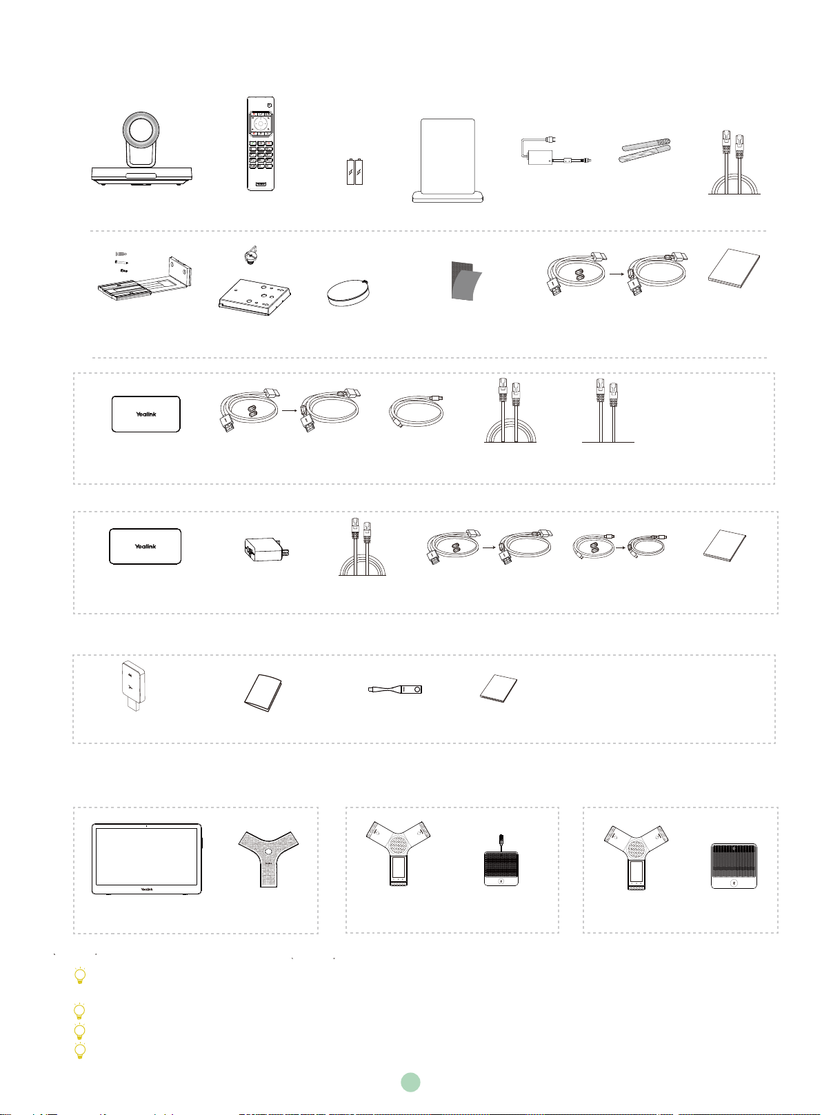
Package Contents
OK
VC800 Codec
+
2
+
2
+
2
Mounting Bracket
and Accessories
VCH50 Video
Conferencing Hub
VCH51
Video Conferencing Hub
VCR11
Remote Control
+
1
VESA Accessory
1.2m
HDMI Cable
(for content sharing)
Interface
Protective Cover
AAA Battery×2
Camera Lens
Privacy cover
(One Velcro is on the bracket)
1.2m
Mini-DP Cable
VCH50 Wired Sharing Package
7.5m
Ethernet Cable
Acrylic board
Velcro×2
7.5m
Ethernet Cable
0.6m
HDMI Cable
(for content sharing)
Power Adapter
1.8m
HDMI Cable×2
(for the display device)
0.5 m
Ethernet Cable
0.6m
USB Type-C Cable
(for content sharing)
Cable Tie×5
3m
Ethernet Cable
VC800
Quick Start Guide
VCH51
Quick Start Guide
VCH51 Wired Sharing Package
Wi-Fi USB Dongle WF50
WF50 User Guide
WPP20 Wireless
Presentation Pod
WPP20 Quick Start Guide
Wireless Sharing Package
Optional Accessories
CTP20
A Package
VCM34×2
CP960
Conference Phone
CPE90 Wired
Expansion Mic×2
B Package
We recommend that you use the accessories provided or approved by Yealink. The use of unapproved third-party accessories may
result in reduced performance.
VC800 endpoint can work with VCH50/VCH51 Wired Sharing package or Wireless Sharing package for sharing content.
VC800 endpoint can work with A package, B package or C package.
Put the magnet rings on the HDMI cable to prevent electromagnetic interference.
CP960
Conference Phone
C Package
CPW90 Wireless
Mic×2
1
Page 3
System Installation
Select one of the following installation methods based on your site requirements:
.
Put on a Flat Surface
.
Mount on top of a TV
.
Mount on a wall
.
Mount on a ceiling
.
Mount onto a TV stand or a tripod
Put on a Flat Surface
You can put the system on a conference room table, and make sure that the slope is not more than 15 degrees so that the system
can operate correctly.
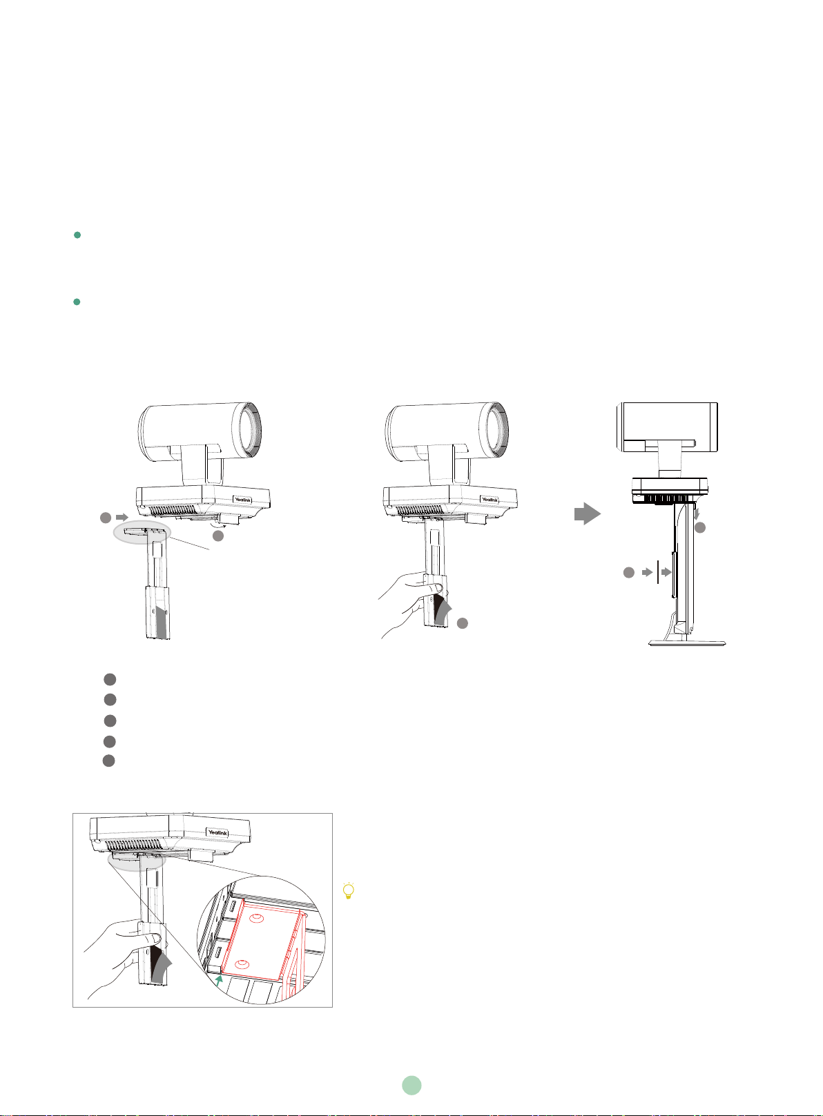
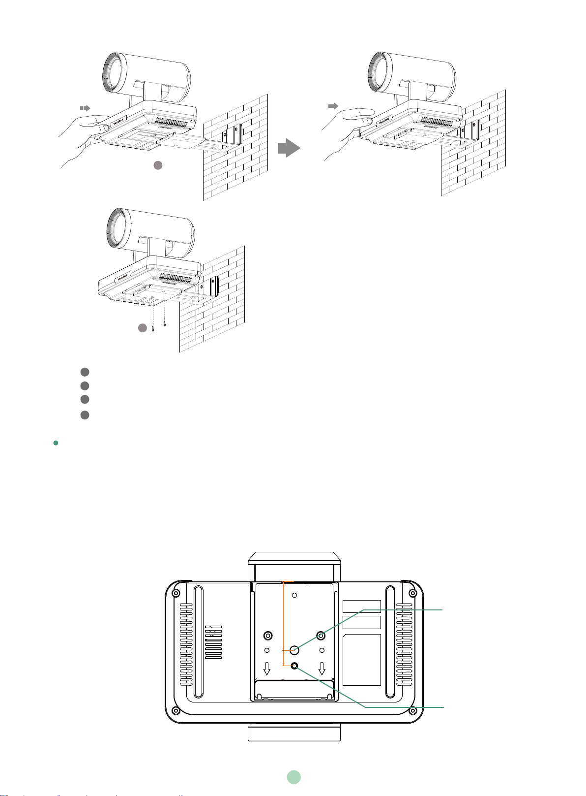
Mount on top of a TV
The system may fall down when the thickness of the TV is more than 100 mm. In this situation, do not mount the system on the
top of a TV.
Please choose the following installation method when the thickness of the TV is between 16mm and 55mm.
2
Steps:
Open the baffle.
1
3
2
Push the bracket along the track of the V800 codec.
Remove one Velcro.
3
Put the bracket on the top of the TV.
4
5
Stick a Velcro onto the back of the TV, and make sure that the bracket and the back of the TV are tightly positioned against each
other.
1
Pay attention to the direction of the bracket
If your system cannot be mounted on the top of a TV when the bracket has
reached the given location, remove the bracket, and then convert its direction.
Refer to the following section for more information.
4
5
3
TV
2
Page 4
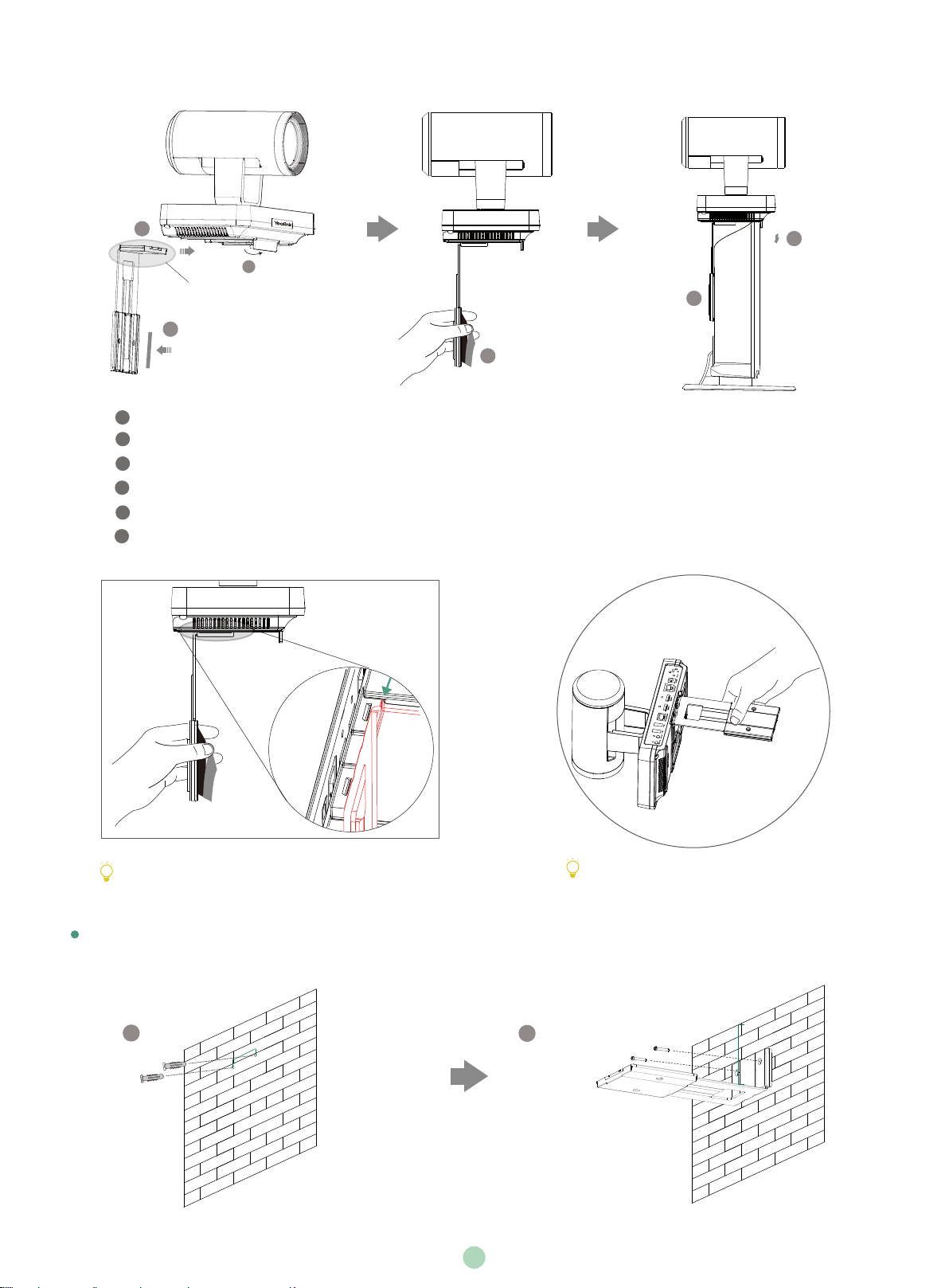
Please choose the following installation method when the thickness of the TV is between 50mm and 100 mm.
2
Pay attention to the direction of the bracket
3
Steps:
Open the baffle.
1
2
3
Push the bracket along the track of the system.
3
Stick a Velcro onto the bracket.
4
Remove one Velcro.
Put the bracket on the top of the TV.
5
Stick a Velcro onto the back of the TV, and make sure that the bracket and the back of the TV are tightly positioned against
6
each other.
5
1
6
4
TV
If your system cannot be mounted on the top of a TV
when the bracket has reached the given location, you
should choose other installation methods.
Mount on a Wall
The recommended height is 1.55m-1.85m above the ground.
1
48mm
X
Do not pick up the bracket which connects
with a system, the system may
fall down in this situation.
Screw specification: T4×30
2
300mm
Hole depth: 30mm
Hole diameter: 6mm
3
Page 5
3
4
Screw specification: M3×8
Steps:
Punch holes into the wall and then insert the expansion bolts.
1
Secure the bracket using the T4×30 screws.
2
3
Push the system along the track of the bracket.
4
Secure the system onto the bracket using the M3×8 screws.
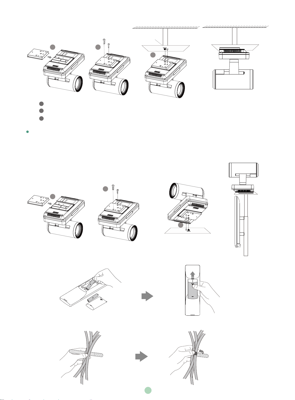
Mount on a Ceiling
If you choose the ceiling-mounted installation, you need to purchase a bracket separately. The bracket must meet the following
requirements:
.
Able to bear the weight of at least 10.5kg (23.15 lb.) and the thickness must be between 2mm (0.08 in.) and 3 mm (0.12 in.).
.
Comes with a location pillar, which can be inserted into the location hole of the VESA accessory.
.
The distance between the screw on the bracket and the location pillar must be 14 mm (0.55 in.).
62.5mm
(2.46in.)
Screw hole
6.0 mm(0.24 in.) in depth
14.0mm
(0.55in.)
4
Location hole
5.0 mm(0.20 in.) in diameter
Page 6
Screw specification: M3×8
1 2
Screw specification:
1/4”-20 UNC
3
Steps:
Push the VESA accessory along the track of the system.
1
2
Secure the VESA accessory to the system using the M3×8 screws.
Align the location pillar at the location hole, and then secure the bracket to the VESA accessory using the 1/4”-20 UNC screw.
3
Mount onto a TV Stand or a Tripod
You need to purchase a TV stand or a tripod separately. The TV stand or tripod has the same requirements as the backet used in the
ceiling-mounted installation method.
The installation steps are the same as the ceiling-mounted installation steps.
Screw specification: M3×8
2
1
3
Screw specification:
1/4”-20 UNC
TV Stand
Remote Control Installation
Cable Ties Installation
5
Page 7
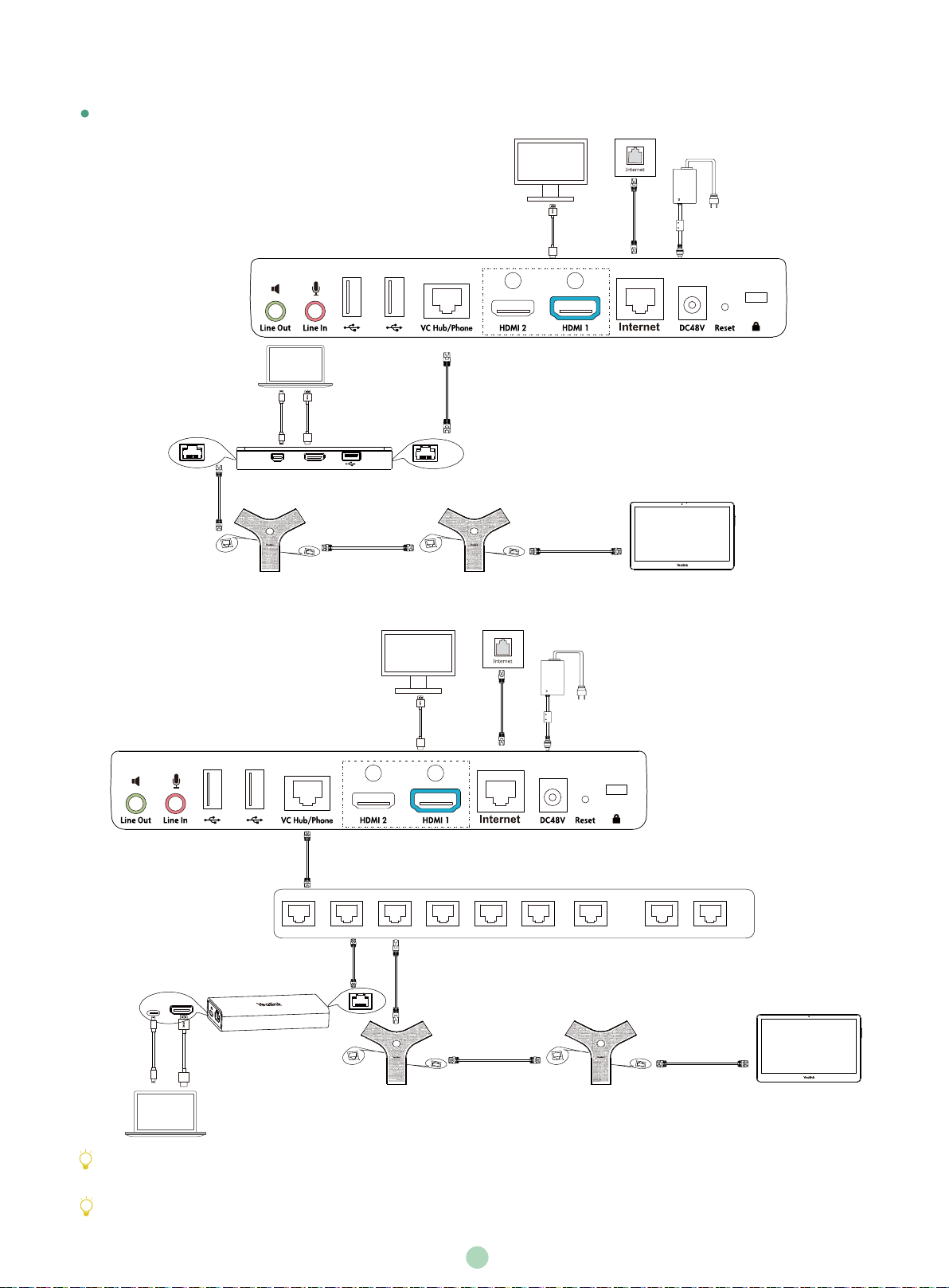
Connections
If endpoint works with A package, do the following:
A: For VCH50 video conferencing hub:
Display×2
PC
1.2m
Mini-DP Cable or
Audio
3m
Ethernet Cable
1.2m
HDMI Cable
MINI DP HDMI
VCH50
3m
Ethernet Cable
PoE
VCM34
B: For VCH51 video conferencing hub:
PoE
Display×2
1.8m
HDMI Cable
7.5m
Ethernet Cable
Codec
VCM34
3m
Ethernet Cable
7.5m
Ethernet Cable
Power Adapter
CTP20
0.6m USB
Type-C Cable
IEEE 802.3af
compliant PoE Switch
HDMI
PC
0.6m
or
HDMI Cable
PC
7.5m
Ethernet Cable
7.5m
Ethernet Cable
VCH51
1.8m
HDMI Cable
PoE
PoE
VCM34
3m
Ethernet Cable
3m
Ethernet Cable
3m
Ethernet Cable
Power Adapter
PoE
VCM34
...
7.5m
Ethernet Cable
CTP20
The system should be used with Yealink original power adapter (48V/0.7A) only. The use of the third-party power adapter may
cause the damage to the system. The cable should be replaced at once if its skin is broken.
If you do not need the VCH50/VCH51 video conferencing hub to share content, you can connect the VC Hub/Phone port on the system
to the PoE port on the VCM34 directly.
6
Page 8
If endpoint works with B package, do the following:
A: For VCH50 video conferencing hub:
Display×2
CP960
CPE90 Wired
Expansion
0.5m
Ethernet Cable
CPE90 Wired
Expansion
1.2m
Mini-DP Cable or
Audio
B: For VCH51 video conferencing hub:
PC
MINI DP HDMI
VCH50
1.2m
HDMI Cable
1.8m
HDMI Cable
Display×2
3m
Ethernet Cable
1.8m
HDMI Cable
Codec
3m
Ethernet Cable
7.5m
Ethernet Cable
Power Adapter
Power Adapter
7.5m
Ethernet Cable
0.6m USB
Type-C Cable
IEEE 802.3af
compliant PoE Switch
HDMI
PC
0.6m
or
HDMI Cable
7.5m
Ethernet Cable
VCH51
PoE
CPE90 Wired
Expansion
0.5m
Ethernet Cable
CPE90 Wired
Expansion
...
CP960
PC
If you do not need the VCH50VCH51 video conferencing hub to share content, you can connect the VC Hub/Phone port on the system
to the PoE port on the CP960 conference phone directly.
When CP960 conference phone is connected to the endpoint, the 3.5mm audio output port and the Micro USB port are not available.
7
Page 9

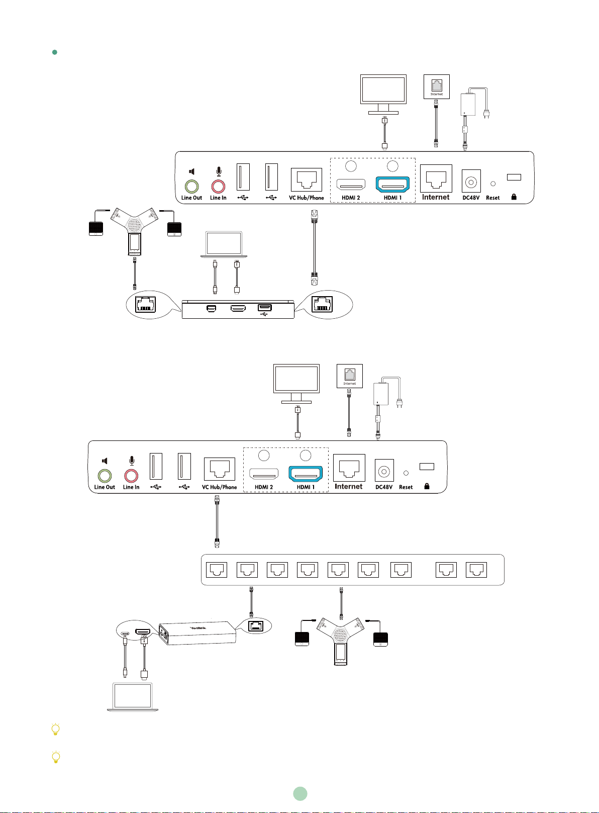
If endpoint works with C package, do the following:
A: For VCH50 video conferencing hub:
Display×2
CP960
0.5m
Ethernet Cable
B: For VCH51 video conferencing hub:
1.2m
Mini-DP Cable or
Audio
MINI DP HDMI
PC
VCH50
1.2m
HDMI Cable
7.5m
Ethernet Cable
1.8m
HDMI Cable
1.8m
HDMI Cable
Codec
Display×2
3m
Ethernet Cable
3m
Ethernet Cable
Power Adapter
Power Adapter
7.5m
Ethernet Cable
...
7.5m
Ethernet Cable
0.6m USB
Type-C Cable
PC
HDMI
or
PC
0.6m
HDMI Cable
PoE
VCH51
0.5m
Ethernet Cable
CP960
The CPW90 wireless microphones and endpoint are automatically paired from the factory.
To register the CPW90 to the CP960 conference phone, do the following:
1. Put the CPW90 on the charger cradlet and connect the micro USB port on the charger cradle to the USB port on the CP960.
The CPW90 enters the registration mode automatically. And the mute LED indicator on the CPW90 fast flashes yellow.
2. Tap Settings->Wireless Microphone->AddWireless Micophone on the CP960.
3. Long press the Mute key on the CPW90 for 5s into phone registration.
8
IEEE 802.3af
compliant PoE Switch
Page 10

Wireless Sharing
PC
WPP20 Wireless Presentation Pod WF50 Wi-Fi USB Dongle
For more information on WPP20 wireless presentation pod, refer to Yealink WPP20 Wireless Presentation
Pod Quick Start Guide.
Network Environment
Bandwidth Requirements
Video Resolution Recommended Bandwidth
Full HD 1080P 1.3Mb
People 1080P+Content 1080P 2.6Mb
Both downlink bandwidth and uplink bandwidth should meet above requirements.
The bandwidth mentioned above is based on a two-way call. Bandwidth in head office should be increased along with the growing
number of connected branch offices.
Network Deployment
Choose Cloud deployment or traditional deployment according to your need.
Cloud Deployment
Cloud deployment does not need complex network settings. You only need to get account information from your system administrator, and
log into video conference platform.
Do the following to log into video conference platform via remote control:
1. Select More->Setting->Advanced (Default Admin Password:0000)->Video Conference Platform.
2. In the Cloud Account field, check the Enabled checkbox.
3. Select the desired platform from the pull-down list of Platform Type.
4. Configure the desired platform and log in.
Traditional Deployment
If you deploy the system in the head office, make sure it is reachable from public network.
If you deploy the system in the branch office, use intelligent traversal to deploy it or just follow the same steps as for the head office.
Head Office
If you deploy the system in the head office, at least one static public IP address is required to allow branch offices to connect.
Do one of the following to deploy the system:
Option1: Assign a static public IP address to your system.
Option2: If you deploy the system in an Intranet (behind the firewall), assign a static private IP address to it and do port mapping on the firew all.
Configure a Static IP
The following introduces how to use the remote control to configure a static IPv4 address:
1. Select More->Setting->Advanced (Default Admin Password:0000)->Wired Network.
2. Select IPv4 from the pull-down list of IP Mode.
3. Select IPv4, and then press OK key.
4. Uncheck the DHCP checkbox.
9
Page 11

5. Enter the IP address, subnet mask, gateway and DNS information in corresponding fields.
6. Save the change.
The display device prompts “Reboot now?”
7. Select OK to reboot the
system.
.
Configure Port Mapping
If you deploye system in an Intranet, you must forward the following ports to the public network on the firewall, so that your system can
receive a public-to-private call.
Protocol Type
UDP/TCP
TCP/UDP
TCP
TCP/UDP
H.323 signal port
Audio & Video media stream port
Web management port( optional )
SIP( optional )
PortFunction
1719-1720
50000-51000
443
5060-5061
Branch Office
If you deploy system in the branch office, do one of the following to deploy it:
Option1: Deploy the system following the same steps as for the head office. In this way, both inbound and outbound calls are available.
Option2: Deploy the system using intelligent traversal. You only need to assign a private IP address to your system. Make sure this
private IP address can access the public network. Only outbound calls are available when using this method.
When you use intelligent traversal to deploy your system, you have to open following ports on your firewall if they are restricted.
Protocol Type
UDP/TCP
TCP/UDP
TCP/UDP
H.323 signal port
Audio & Video media stream port
SIP( optional )
PortFunction
1719-1720
50000-51000
5060-5061
It is recommended that you forward the web management port(443/TCP) to the public network, so that the head office can remotely
manage the branch office.
Troubleshooting
Testing Connectivity
After installation and deployment, you can test the system by dialing the Yealink Demo Room (117.28.251.50 or 117.28.234.45). If you can’t dial
out successfully, please contact your IT administrator to check the network.
Configuring Static NAT
If you do not use Cloud platform and deploy your system in an Intranet, you have configured port mapping on the firewall or gateway, but you
find that local system appears black screen and you cannot hear sound when you call Yealink Demo or other systems. The most likely reason is
that the firewall or gateway in your environment does not support the ALG feature. In this situation, please take the following actions so that the
static NAT feature on the system can solve this problem.
To configure static NAT via the remote control:
1. Select More->Setting->Advanced (Default Admin Password:0000)->NAT/Firewall.
2. Select Auto from the pull-down list of Type, the system will obtain public IP address automatically.
3. If the system does not obtain a public IP address automatically, select Manual Settings from the pull-down list of Type, and then enter
the public IP address in the Public IP Address field.
4. Save the change.
10
Page 12

包装清单
OK
VC800主机
+
2
+
2
+
2
支架配件
(用于安装主机)
VCH50接线盒
VCH51接线盒
VCR11遥控器
魔术贴x2
(一套已贴在支架上)
1.2米Mini-DP线
(用于分享辅流)
接口保护罩
7号电池x2
7.5米网线
亚克力牌
+
1
VESA配件
1.2米HDMI线
(用于分享辅流)
VCH50有线辅流套件
0.6米HDMI线
(用于分享辅流)
VCH51有线辅流套件
束线带x 5
镜头隐私盖
3米网线
7.5米网线
0.6米USB Type-C线
(用于分享辅流)
电源适配器
0.5米网线
VC800
快速入门指南
VCH51
快速入门指南
1.8米HDMI线x 2
(用于接显示设备)
VC800
最佳部署实践方案
USB无线网络适配器WF50
WF50用户指南
WPP20 无线传屏助手
无线辅流套件
WPP20快速入门指南
可选配件
CP960会议电话
CTP20
CTP20与VCM34套件
VCM34x2
此为A级产品。在生活环境中,该产品可能会造成无线电干扰。在这种情况下,可能需要用户对干扰采取切实可行的措施。
我们推荐使用由Yealink提供或经Yealink认可的配件和线缆,使用未经认可的第三方配件和线缆可能会导致性能的下降。
你可以选择有线辅流或无线辅流套件进行内容共享。
VC800主机可搭配CTP20与VCM34套件或会议电话套件使用。
使用HDMI线前,请套上磁环用于抗电磁干扰。
CPE90有线扩展麦x2
会议电话套件
安装终端
你可以根据实际需要选择安装终端的方式:
平放安装
将终端摆放在水平桌面。如果桌面略有倾斜,请保证倾斜角小于15°,以保证终端的摄像机云台正常运转。
11
Page 13

挂装
当电视厚度范围为16-55mm时,进行以下步骤:
2
步骤:
1
打开终端底部的挡板。
2
3
将支架沿着终端底部轨道推至合适的位置。
3
撕开支架上的魔术贴。
4
将支架挂在电视的上方。
5
在电视背部黏贴魔术贴(魔术贴为一次性,黏贴前注意清洁电视背后),调整支架,使支架和电视的背面完全紧贴。
注意支架的方向
1
5
3
当支架与箭头位置齐平,还不能放置在电视顶上时,请取出支架反向装
配。请参阅下文了解更多信息。
4
电视
槽位边缘
当电视厚度范围为50mm-100mm时,进行以下步骤:
2
1
注意支架的方向
3
12
5
6
电视
4
Page 14

步骤:
1
打开终端底部的挡板。
2
3
将支架沿着终端底部轨道推至合适的位置。
3
在支架上黏贴魔术贴(魔术贴为一次性,黏贴前注意清洁支架)。
4
撕开支架上的魔术贴。
5
将支架挂在电视的上方。
6
在电视背部黏贴魔术贴(魔术贴为一次性,黏贴前注意清洁电视背后),调整支架,使支架和电视的背面完全紧贴。
X
当支架与底壳箭头位置齐平,还不能放置在电视顶上
时,请使用其他安装方式。
电视厚度超过100mm时,请勿使用挂装方式,机器
有跌落风险。
墙装
你可以用支架将终端安装在墙上,终端安装高度建议范围为1.55-1.85m。
48mm
1
打孔直径: 6mm
打孔深度: 30mm
螺丝规格:T4x30
2
请勿手持支架拿起终端,有掉落风险。
300mm
3
13
Page 15

步骤:
4
螺丝规格:M3x8
吊装
你可以自行选购支架来将终端倒挂在天花板上,选购的支架必须满足以下条件:
.
承重至少为10.5kg,厚度建议为2mm-3mm。
.
支架配套一个定位柱,定位柱用来插入VESA配件的定位孔中。
.
支架上的英制螺钉和定位柱的直线距离必须为14mm。
1
在墙上打孔,将膨胀螺栓固定至墙上。
3
2
用T4×30型号的螺丝将支架固定到墙上。
3
将终端底部沿着支架的轨道往里推。
4
用两个M3×8型号螺丝将终端锁在支架上。
螺丝孔
深度:6.0mm
1 2
步骤:
1
将VESA配件沿着终端底部轨道往里推。
3
2
使用两个M3×8型号螺丝将VESA配件锁到终端上。
螺丝规格:M3x8
14.0mm 62.5mm
定位孔
直径:5.0mm
螺丝规格:
1/4-20UNC英制螺钉
3
3
将支架自带的定位柱对准VESA配件的定位孔,并将1/4”-20UNC英制螺钉旋进VESA配件的螺丝孔。
14
Page 16

电视架或三脚架安装
用户可以自行选购电视架或三脚架来固定终端,电视架或三脚架的选购要求与使用吊装方式时的支架要求相同。电视架或三脚架安装步骤与
吊装步骤相同。
螺丝规格:M3x8
2
1
电视架
3
螺丝规格:
1/4-20UNC英制螺钉
连接终端
如果终端搭配CTP20和VCM34套件,请按下图完成连接:
A: 对于VCH50有线辅流分享:
Audio
3米网线
VCH50
MINI DP HDMI
1.8米HDMI线
7.5米网线
Codec
显示设备x2
电源适配器
3米网线
PoE
VCM34
3米网线
PoE
VCM34
15
7.5米网线
CTP20
Page 17

B: 对于VCH51有线辅流分享:
显示设备x2
电源适配器
IEEE 802.3af 标准
PoE交换机
VCH51
HDMI
PC
0.6米
USB Type-C线 或 0.6米HDMI线
PC
1.8米HDMI线
3米网线
7.5米网线
...
PoE
3米网线
PoE
VCM34
3米网线
PoE
VCM34
7.5米网线
CTP20
如果你无需使用VCH50/VCH51进行演示,可以使用网线将VCM34的PoE接口直接连在终端的VC Hub/Phone接口上。
我们要求使用Yealink原装电源(48V/0.7A),使用第三方电源可能会导致终端损坏。如果使用过程中发现线缆破皮,请立即更换。
如果终端搭配电话会议套件,请按下图完成连接:
A: 对于VCH50有线辅流分享:
显示设备x2
电源适配器
3米网线
有线扩展麦
1.8米HDMI线
CP960会议电话
7.5米网线
有线扩展麦
0.5米网线
Audio
VCH50
MINI DP HDMI
Codec
16
Page 18

B: 对于VCH51有线辅流分享:
显示设备x2
电源适配器
IEEE 802.3af 标准
PoE交换机
VCH51
HDMI
PC
0.6米
USB Type-C线 或 0.6米HDMI线
1.8米HDMI线
7.5米网线
3米网线
...
0.5米网线
PoE
PC
有线扩展麦
CP960会议电话
有线扩展麦
如果你无需使用VCH50/VCH51进行演示,可以使用7.5米网线将CP960会议电话的Internet接口直接连在终端的VC Hub/Phone
接口上。
CP960会议电话连接在终端上时,3.5mm音频输出接口和Micro USB接口不可用。
连接无线辅流
PC
WPP20无线传屏助手 WF50 USB无线网络适配器
想要了解WPP20无线传屏助手的详细信息,请参阅亿联WPP20无线传屏助手快速入门指南。
17
Page 19

使用遥控器与束线带
视频会议室部署
视频会议室的部署可分为如下几个模块:光线、摄像机放置、拾音/声音播放、画面显示、接线。以下是针对这些模块的具体建议,在会
议室装修与视频会议设备部署的过程中可参考以下内容取得更佳的视频会议效果。
光线
会议室的灯光应更多地聚焦在会议桌与参会人的位置,以
45° 斜照向参会人面部是较为理想的光照条件。
如会议室原有的光线不足可考虑加装平面光源,色温以
4000~5000k,光照强度以300~500lux为宜。光线充足与
否可以视频画面中面部肤色是否真实还原作为评判标准。
即使会议室采光条件良好,也建议在会议过程中打开会议室
灯光,以确保会议桌与参会人区域有充足且均匀的光照度。
摄像机避免正对强光源,例如窗户。以免出现人物图像逆光
现象。如果摄像机不可避免地朝向窗口,可装配窗帘。
45
。
摄像机放置
根据实际的会议室情况,摄像机安装高度建议在 1.55~1.85
m之间。如果是较大型的会议室/会场则不受限于此建议高
度,可根据被摄物体距离确定摄像机高度。
18
Page 20

1.55 (m)
建议将摄像机放置于电视顶部水平居中的位置。如果显示设
备较大(大于80寸)或应用了拼接屏,可考虑将摄像机固定
在显示设备下方,但应高于会议桌高度。为提升视频会议中
的眼神交流与互动感,尽可能将摄像机靠近显示对方视频画
面的屏幕。
投影+电视作为显示设备的情况下,将电视架推车尽可能靠
近投影幕布,摄像机放置于电视上靠近投影幕布的一侧。
面积较大的会议室/会场可考虑吊顶倒装摄像机,但需避免
摄像机直接安装于天花板推荐使用吊架降低摄像机高度。需
注意摄像机高度/角度调节范围相对第一排参会者距离的关
系。以摄像机离地 2.5m为例,第一排参会者与摄像机的距
离应至少 2m为宜。
如需多角度画面或更广的视角范围,可选购扩展摄像机
VCC22。
拾音/声音播放
1.85 (m)
参会者与麦克风的距离在0.5~1.5m范围内可获得最佳的
拾音效果。
当会议室面积大于50㎡或会议桌长于4m时建议配备扩展
麦克风或采用多个麦克风。
会议电话的内置扬声器通常能够满足60㎡以下会议室的
需求。当会议室面积大于60㎡时可考虑级联会议电话或
连接外部音响,确保声音有效覆盖所有参会人。
如使用电视扬声器播放声音,将电视音量调整到合适的大
小,避免音量过大出现破音。麦克风应与电视保持一定距
离,建议大于2m。
画面显示
因投影仪的显示效果相对较差且容易受到光照情况影响,
所以建议使用液晶电视作为视频会议的显示设备。如需同
时使用电视和投影仪,尽可能将电视放置在靠近投影仪的
位置,减少视线跨度。
,
1.5 (m)
电视 电视
由于投影效果易受光照情况影响,在使用投影仪时应尽可
能减少照射向投影幕的灯光,增加参会者区域的光照度。
如果使用辅流的需求较多,建议使用双屏显示,如此可同
时全屏观看视频画面与辅流内容。
19
Page 21

线材
尽可能选择具备线材收纳功能的会议桌,以确保桌面整洁
如果会议室未进行走线设计,电视至桌面的线材可使用金
属线槽贴地走线。
遇到线长不够需要更换线材或需要转接的情况,请联系代
理商或拨打技术支持热线咨询技术人员确定线材规格,避
免自行配线影响使用效果,甚至造成不必要的损失。
网络快速部署
网络带宽需求
视频分辨率
全高清视频1080P 1.3Mb
。
电视
建议带宽需求
2.6Mb人像1080P+内容1080P
终端所需网络带宽需求为上下行带宽需求,网络的上行带宽及下行带宽均需要满足需求。
以上带宽需求为两方通话的带宽需求,主会场带宽需要根据分会场数量进行相应的增加。
部署网络
你可以使用云服务方式或传统方式部署终端。
云服务方式部署
云服务方式部署无需复杂的网络配置,登录云平台就可以实现各会场间的互联互通。账号信息请从管理员处获取。
通过遥控器登录平台:
1. 选择更多->设置->高级设置(默认密码:0000)->视频会议服务平台。
2. 勾选启用云功能复选框。
3. 从登录平台下拉框中选择你想要登录的平台。
4. 填写平台登录的相关信息并登录。
传统方式部署
请根据你的会场所处的角色进行设置,主会场必须公网可达,分会场可参考主会场设置或采用智能穿透方式部署。
20
Page 22

部署主会场
如果将终端部署在主会场,则它必须至少拥有一个固定公网IP地址,以便其它终端可以通过网络访问到你的终端,你可以任选以下一
种方式部署主会场:
选项一
:如果你将终端直接部署在公网,请为其设置一个固定的公网IP地址。
选项二
:如果你将终端部署在内网(防火墙后),除了为其设置一个固定的内网IP地址之外,还需要在防火墙上设置端口映射。
设置固定IP地址
以下介绍如何通过遥控器为终端配置一个固定的IPv4地址:
更多->
1. 选择
设置->高级设置(默认密码:0000)->有线网络。
2. 从IP模式下拉框中选择IPv4。
3. 按遥控器的上下方向键选择
DHCP
4. 取消勾选
5. 在相应的区域中输入:IP地址、子网掩码、网关、DNS主服务器和DNS备份服务器。
6. 按遥控器的上下方向键选择保存,再按OK键。
显示器的液晶屏幕提示【需要重启系统使配置生效,是否立即重启?】
7. 选择确认重启终端。
复选框 。
IPv4
,再按OK键。
设置端口映射
如果你将终端部署在内网,您需要在防火墙上将以下端口映射至公网。终端才可以正常接听来自公网的呼叫:
描述 端口 类型
H.323 信令端口
音视频媒体流端口
网页管理端口(可选)
SIP信令端口(可选)
1719-1720
50000-51000
443
5060-5061
UDP/TCP
TCP/UDP
TCP
TCP/UDP
部署分会场
如果将终端部署在分会场,你可以任选以下一种方式部署分会场:
选项一
:分会场可以采用与主会场相同的部署方式。使用该种方式时终端可呼入、可呼出。
选项二
:采用智能穿透方式进行部署,仅需为终端分配一个可访问公网的IP地址即可。使用该种方式时终端只能呼出不能呼入。
采用智能穿透方式部署时,如果你的网络有端口限制,需要开放以下端口权限。
H.323 信令端口
音视频媒体流端口
SIP信令端口(可选)
建议分会场将网页管理端口(443/TCP)映射至公网,以便主会场可以远程管理、支持分会场。
1719-1720
50000-51000
5060-5061
21
19
UDP/TCP
TCP/UDP
TCP/UDP
Page 23

故障排查
测试连通性
完成终端的安装部署后,你可以拨打Yealink Demo环境(117.28.251.50、117.28.234.45)来测试终端是否工作正常,如果无法呼
通Demo环境,请联系网络管理员检查你的内部网络是否通畅。
配置静态NAT功能
如果你将终端部署在内网(防火墙后),并且已在防火墙或网关上配置了端口映射,当跨公网呼叫其他会场的终端或Yealink Demo时,
本地出现黑屏无声的问题,极有可能是因为本会场网络环境中的防火墙或者网关不支持ALG功能。要解决这个问题,使用遥控器开启
终端上的静态NAT功能:
更多->
1. 选择
2. 从类型下拉框中选择自动,终端将自动获取当前网络的公网IP地址。
3. 如果终端未能自动获取到公网IP地址,你可以在类型下拉框中选择手动设置,然后在公网IP地址区域输入当前网络的公网IP地址。
4. 按遥控器的上下方向键选择保存,再按OK键保存当前配置。
设置->高级设置(默认密码:0000)->NAT/防火墙。
22
Page 24

Regulatory Notices
Operating Ambient Temperatures
Operating temperature: +32 to 104°F (0 to 40°C)
Relative humidity: 5% to 90%, noncondensing
Storage temperature: -22 to +160°F (-30 to +70°C)
Warranty
Our product warranty is limited only to the unit itself, when used normally
in accordance with the operating instructions and the system environment.
We are not liable for damage or loss resulting from the use of this product,
or for any claim from a third party. We are not liable for problems with
Yealink device arising from the use of this product; we are not liable for
financial damages, lost profits, claims from third parties, etc., arising from
the use of this product.
Explanation of the symbols
DC symbol
is the DC voltage symbol.
WEEE Warning symbol
To avoid the potential effects on the environment and human health
as a result of the presence of hazardous substances in electrical and
electronic equipment, end users of electrical and electronic
equipment should understand the meaning of the crossed-out wheeled bin
symbol. Do not dispose of WEEE as unsorted municipal waste and have to
collect such WEEE separately.
Restriction of Hazardous Substances Directive (RoHS)
This device complies with the requirements of the EU RoHS Directive.
Statements of compliance can be obtained by contacting support@yealink.com.
Safety Instructions
Save these instructions. Read these safety instructions before use!
General Requirements
Before you install and use the device, read the safety instructions
carefully and observe the situation during operation.
During the process of storage, transportation, and operation, please
always keep the device dry and clean, avoid collision and crash.
Please attempt not to dismantle the device by yourself. In case of any
discrepancy, please contact the appointed maintenance center for repair.
Please refer to the relevant laws and statutes while using the device.
Legal rights of others should be respected as well.
Environmental Requirements
Place the device at a well-ventilated place. Do not expose the device
under direct sunlight.
Keep the device dry and free of dusts.
Do not place the device on or near any inflammable or fire-vulnerable
object, such as rubber-made materials.
Keep the device away from any heat source or bare fire, such as a candle
or an electric heater.
Operating Requirements
Do not let a child operate the device without guidance.
Do not let a child play with the device or any accessory in case of
accidental swallowing.
Please use the accessories provided or authorized by the manufacturer
only.
The power supply of the device shall meet the requirements of the input
voltage of the device. Please use the provided surge protection power
socket only.
Before plugging or unplugging any cable, make sure that your hands are
completely dry.
Do not spill liquid of any kind on the product or use the equipment near
water, for example, near a bathtub, washbowl, kitchen sink, wet
basement or near a swimming pool.
During a thunderstorm, stop using the device and disconnect it from the
power supply. Unplug the power plug and the Asymmetric Digital
Subscriber Line (ADSL) twisted pair (the radio frequency cable) to avoid
lightning strike.
About Yealink
If the device is left unused for a rather long time, disconnect it from the
power supply and unplug the power plug.
When there is smoke emitted from the device, or some abnormal noise
or smell, disconnect the device from the power supply, and unplug the
power plug immediately.
Contact the specified maintenance center for repair.
Do not insert any object into equipment slots that is not part of the
product or auxiliary product.
Before connecting a cable, connect the grounding cable of the device
first. Do not disconnect the grounding cable until you disconnect all other
cables.
Cleaning Requirements
Before cleaning the device, disconnect it from the power supply.
Use a piece of soft, dry and anti-static cloth to clean the device.
Keep the power plug clean and dry.
Troubleshooting
The unit cannot supply power to device other than Yealink device.
There is a bad connection with the plug.
1. Clean the plug with a dry cloth.
2. Connect it to another wall outlet.
The usage environment is out of operating temperature range.
1. Use in the operating temperature range.
The cable between the unit and the Yealink device is connected incorrectly.
1. Connect the cable correctly.
You cannot connect the cable properly.
1. You may have connected a wrong Yealink device.
2. Use the correct power supply.
Some dust, etc., may be in the port.
1. Clean the port.
Contact your dealer or authorized service facility for any further questions.
FCC Statement
This device complies with part 15 of the FCC Rules. Operation is subject to the
following
two conditions: (1) this device may not cause harmful interference, and (2) this
device must accept any interference received, including interference that may
cause undesired operation.
Any Changes or modifications not expressly approved by the party responsible
for compliance could void the user's authority to operate the equipment.
IC Statement
This device complies with Industry Canada’s licence-exempt RSSs. Operation is
subject to the following two conditions:
(1) this device may not cause interference; and
(2) this device must accept any interference, including interference that may
cause undesired operation of the device. CAN ICES-3(B)
Le présent appareil est conforme aux CNR d’Industrie Canada applicables aux
appareils radio exempts de licence. L’exploitation est autorisée aux deux
conditions suivantes :
(1) l’appareil ne doit pas produire de brouillage;
(2) l’utilisateur de l’appareil doit accepter tout brouillage radioélectrique subi,
même si le brouillage est susceptible d’en compromettre le
fonctionnement.NMB-3(B)
Contact Information
YEALINK NETWORK TECHNOLOGY CO.,LTD.
309, 3rd Floor, No.16, Yun Ding North Road, Huli District, Xiamen City, Fujian, P.R. C
YEALINK (EUROPE) NETWORK TECHNOLOGY B.V.
Strawinskylaan 3127, Atrium Building, 8th floor, 1077ZX Amsterdam, The Netherlands
YEALINK (USA) NETWORK TECHNOLOGY CO., LTD.
999 Peachtree Street Suite 2300, Fulton, Atlanta, GA, 30309, USA
Made in China
Yealink is a global leading provider of enterprise communication and collaboration solutions, offering video conferencing service to
worldwide enterprises. Focusing on research and development, Yealink also insists on innovation and creation. With the outstanding
technical patents of cloud computing , audio, video and image processing technology, Yealink has built up a panoramic collaboration
solution of audio and video conferencing by merging its cloud services with a series of endpoints products. As one of the best providers
in more than 140 countries and regions including the US, the UK and Australia, Yealink ranks No.1 in the global market share of SIP
phones shipments.
Technical Support
Visit Yealink WIKI (http://support.yealink.com/) for the latest firmware, guides, FAQ, Product documents, and more. For better service, we
sincerely recommend you to use Yealink Ticketing system (https://ticket.yealink.com) to submit all your technical issues.
VC800 - EN+CN
YEALINK(XIAMEN) NETWORK TECHNOLOGY CO.,LTD.
Web: www.yealink.com
Copyright
TECHNOLOGY CO.,LTD
©2020
YEALINK(XIAMEN) NETWORK
.All rights reserved.
 Loading...