

Page 1
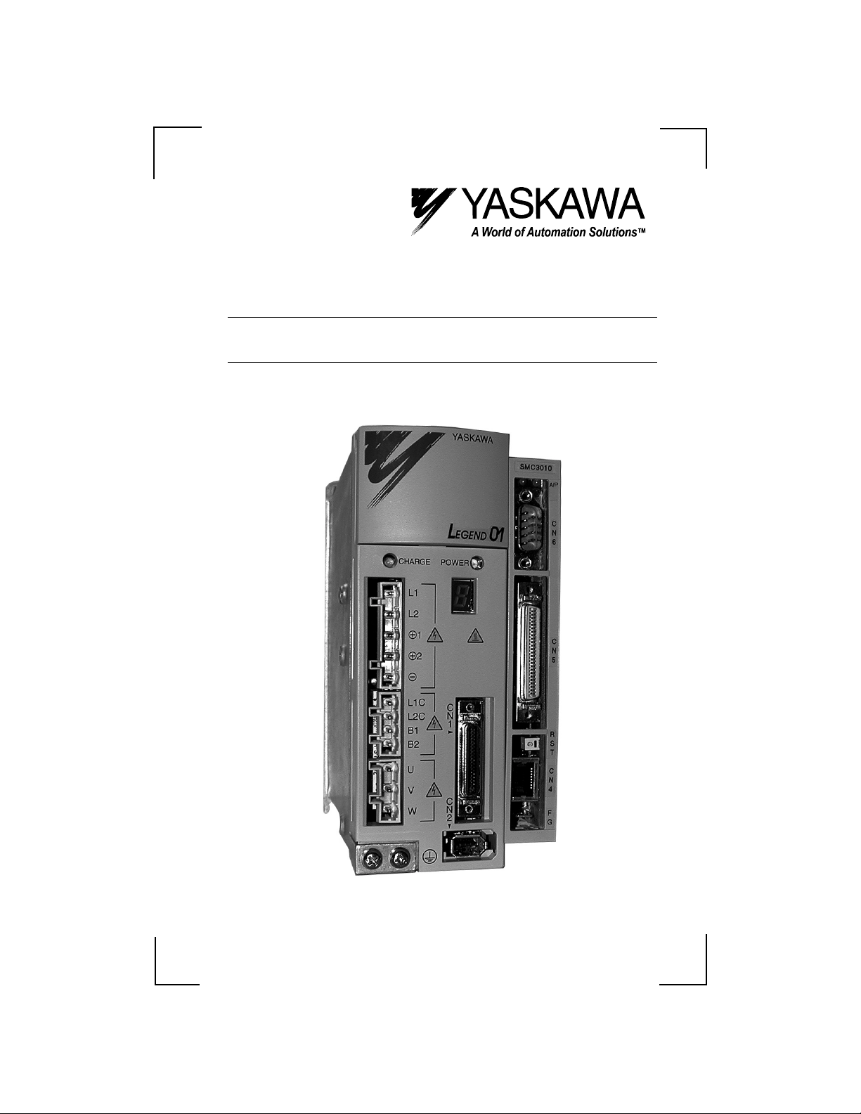
LEGEND-MC Installation Guide
LEGEND-MC Installation Guide
Upon receipt of the product and prior to initial operation, read these
instructions thoroughly and retain for future reference.
Page 2

LEGEND-MC Installation Guide
Page 3

LEGEND-MC Installation Guide
WARNING
YASKAWA manufactures component parts that can be used in a wide variety of industrial
applications. The selection and application of YASKAW A products remain the responsibility
of the equipment designer or end user. YASKAWA accepts no responsibility for the way its
products may be incorporated into the final system design.
Under no circumstances should any YASKAWA product be incorporated into any product or
design as the exclusive or sole safety control. Without exception, all controls should be
designed to detect faults dynamically under all circumstances. All products designed to
incorporate a component part manufactured by Y ASKAWA must be supplied to the end user
with appropriate warnings and instructions as to that part’s safe use and operation. Any
warnings provided by Yaskawa must be promptly provided to the end user.
YASKAWA offers an express warranty only as to the quality of its products in conforming to
standards and specifications published in YASKAWA’S manual. NO OTHER WARRANTY,
EXPRESS OR IMPLIED, IS OFFERED. YASKAWA assumes no liability for any personal
injury, property damage, losses or claims arising from misapplication of its products.
Page 4

LEGEND-MC Installation Guide
Page 5

LEGEND-MC Installation Guide
TABLE OF CONTENTS
Introduction .......................................................................... 1
Part Numbers ....................................................................... 2
Startup ................................................................................. 3
Mounting the LEGEND-MC to the LEGEND Amplifier.... 3
Mounting Orientation ...................................................... 3
Front Panel Description ....................................................... 4
Power/Connections Wiring - Single Phase .......................... 5
Power/Connections Wiring - Three Phase ........................... 6
Cable Shielding, Segregation and Noise Immunity .............7
I/O Connections (50-pin CN5) ............................................. 8
Analog I/O ............................................................................ 9
Analog Input ................................................................... 9
Analog Output .............................................................. 10
Digital I/O ... .. .. ............... ... ............... .. ................ .. ............... 11
Digital Input .................................................................. 11
Digital Outpu t ............ ............... .. ................ .. .. ............. 12
Emergency Stop Chain....................................................... 13
Serial Communication ........................................................ 14
External encoder Specifications ......................................... 15
Dedicated Inputs...................... .. ......................... ................ 16
Physical Specifications ....................................................... 17
Hardware Specifications ..................................................... 17
Cable Diagram and Dimensional Drawings........................ 18
Page 6

LEGEND-MC Installation Guide
NOTES:
Page 7

LEGEND-MC Installation Guide
Introduction
The LEGEND-MC is a single axis Ethernet motion
controller designed for use exclusively with
Yaskawa’s LEGEND Digital Torque Amplifier.
It provides a structured text programming environment and the ability to perform many modes of
motion including camming, gearing, and contouring. High speed product registration is also available as a standard feature.
Additionally, point-to-point control and communications over the Ethernet connections are standard
features. The Ethernet functi on allo ws mu l ti ple
handles or devices to communicate with the controller.
1
Page 8

LEGEND-MC Installation Guide
Part Numbers
Description Part Number
Motion Controller with Ethernet Interface SMC3010
a)
SMC3010
1.0m 50 Pin I/O Cable JZSP-CKI01-1 (A)
2.0m 50 Pin I/O Cable JZSP-CKI01-2 (A)
b)
I/O
Serial
3.0m 50 Pin I/O Cable JZSP-CKI01-3 (A)
1.0m 50 Pin I/O Cable (w ith terminal block) JUSP-TA50P
3.0m Port #1 Cable SMCCBL7
c)
YTe r m P r og r am m in g S of t w ar e SM CGUI1
d)
Software
2
Page 9
LEGEND-MC Installation Guide
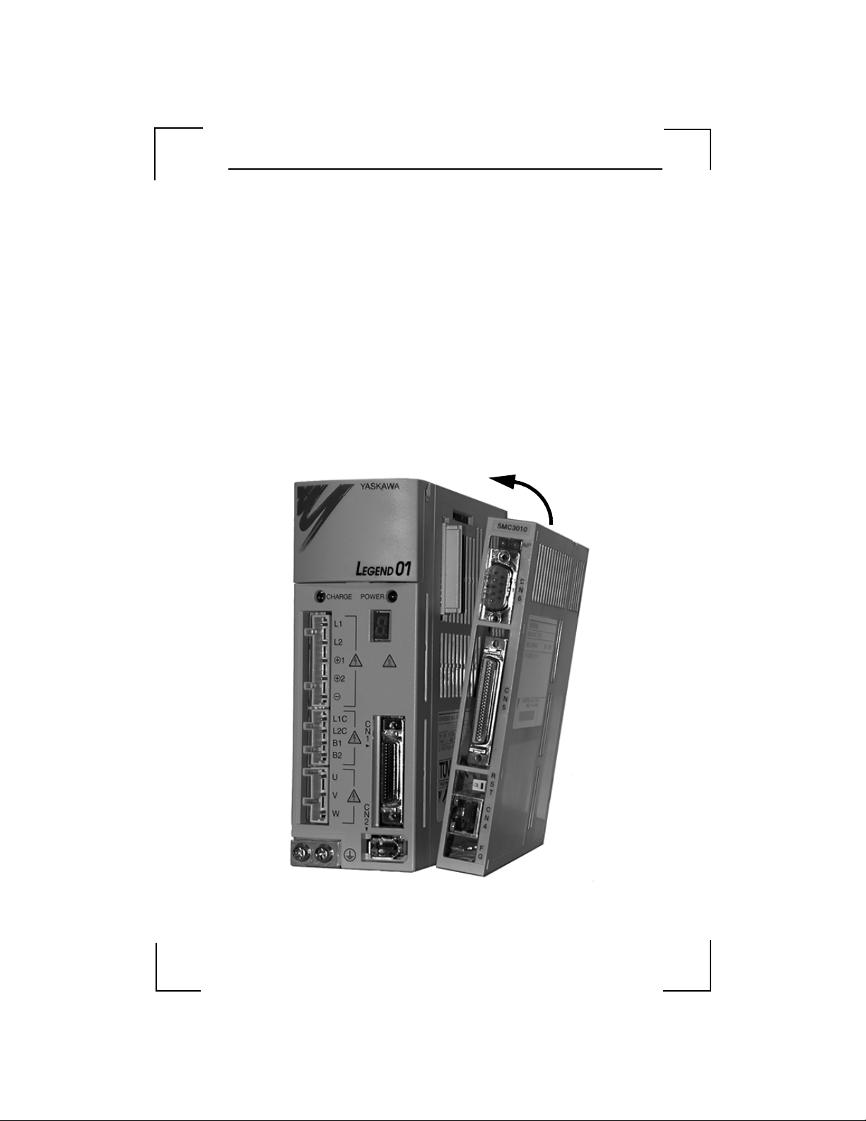
Startup
Mounting the LEGEND-MC to the LEGEND Amplifier
1. Insert the lower two mounting notches of the LEGEND-MC into the
mounting holes at the bottom of the right side of the LEGEND.
2. Push the LEGEND-MC in the direction indicated by the arrow in the
figure below, and insert the upper mounting notches of the LEGENDMC into the upper mounting holes on the right side of the LEGEND.
Mounting Orien tat ion
Mount the LEGEND-MC and LEGEND vertically for proper cooling, as
shown below. Allow a minimum spacing of 10mm around the left and right
sides and 30mm around the top and bottom of the LEGEND-MC/LEGEND
unit.
3
Page 10

LEGEND-MC Installation Guide
Front Panel Description
No. Name Description
(1) Power ONA green LED that indicates +5 VDC power is
(2) Alarm/
Error
(3) CN6 9 pin male D-Sub serial port connector
(4) CN5 3M 50 pin high density I/O connector
(5) RST Reset switch. Causes the controller to reboot, and
(6) Ethernet
status
(7) Ethernet
status
(8) CN4 10 BaseT Ethernet RJ485 Connector
(9) FG Frame ground spade terminal. Connect to ground
applied properly from the LEGEND-MC
amplifier to the controller.
A red LED that will flash on initially at power up
and stay lit for approximately 1-8 seconds. A fter
power up, the LED will illuminate for the
following reasons:
•The axis has a position error greater than the error
limit. The error limit is set by using the command
ER.
•The reset line on the contr oller is held low or is
being affected by noise.
•There is a failure in the cont rol ler and the
processor is resetting itself.
•There is a failure in the ou tput IC which drives
the error signal.
load the application program and parameters from
flash. If the program contains an #AUTO label, it
will automatically execute.
A green LED that is lit when there is an Ether n et
connection to the controller. This LED tests only
for the physical connection, not for an active or
enabled link.
The yellow LED indicates tr affic across the
Ethernet connection. This LED will show both
transmit and rece ive activity across the
connection. If the re is no Ethernet connection or
IP address assigned, the LED wil l flash at regular
intervals to sh ow that the BOOTP pa ckets are
being broadcast.
terminal on LEGEND Amplifier
(2)
(3)
(4)
(5)
(7)
(8)
(9)
(1)
(6)
4
Page 11

LEGEND-MC Installation Guide
Power/Connections Wiring - Single Phase
R
1MCCB
T
Noise Filter
Control
Power
ON
1MC
Servo ON
Control
Power
OFF
Servo
Power
OFF
Emergency
Stop
1MC
SUP
1MC 2MC
2MC
1MC
2MC
YASKAWA
LEGEND01
CHARGE POWER
L1
L2
L3
1
2
L1C
L2C
B1
B2
B3
U
V
W
C
SUP
C
N
6
C
N
5
N
1
C
N
2
R
S
T
C
N
4
F
G
Notes: The LEGEND-MC receives its power from the LEGEND amplifier
through the side interface connector, however, the digital I/O receives its power
from pins 46, 47, 48, and 49 on the I/O connector.
For maximum noise immunity, connect the FG to a ground terminal on the
sub panel or to the ground terminal on the LEGEND.
5
Page 12

LEGEND-MC Installation Guide
Power/Connections Wiring - Three Phase
R
T
1MCCB
S
Noise Filter
Control
Power
ON
1MC
Servo ON
Control
Power
OFF
Servo
Power
OFF
Emergency
Stop
1MC
1MC
SUP
2MC
2MC
1MC
2MC
CHARGE
L1
L2
L3
1
2
L1C
L2C
B1
B2
B3
U
V
W
YASKAWA
LEGEND01
POWER
C
N
1
C
N
2
SUP
C
N
6
C
N
5
R
S
T
C
N
4
F
G
Notes: The LEGEND-MC receives its power from the LEGEND amplifier
through the side interface connector, however, the digital I/O receives its power
from pins 46, 47, 48, and 49 on the I/O connector.
For maximum noise immunity, connect the FG to a ground terminal on the
sub panel or to the ground terminal on the LEGEND.
6
Page 13

LEGEND-MC Installation Guide
P
P
P
Cable Shielding, Segregation and Noise
Immunity
Proper
SMC 3010
a)
Connector Case
b)
Wrong
a)
Connector
Connector
Case
ROPER
Shield tied back at
terminal block.
Case
WRONG
Shield grounded at
more than one point.
Terminal Block
Terminal Block
Terminal Block
Shields ti e d
back at device
ROPER
Shield connected across
terminal block.
Shields ti e d
back at device
ROPER
Shields of field
cables grounded at
one point
Shields tied
back at device
b)
Connector
Case
Terminal Block
Shields tied
back at device
WRONG
Shields of field
cables ungrounded
7
Page 14

LEGEND-MC Installation Guide
I/O Connections (50-pin CN5)
CN5
1
1
2
3
4
5
6
7
8
9
10
11
12
13
14
15
16
17
18
19
20
21
22
23
24
25
26
27
28
29
30
31
32
33
34
35
36
37
38
39
40
41
42
43
44
45
46
47
48
49
50
Analog 1
Analog 2
+5 Filtered Output power
-12 Filtered Output power
+12 Filtered Output power
Output compare
External encoder AExternal encoder A+
External encoder BExternal encoder B+
Abort Input
Reverse li mi t switch
Home Input
Forward limit switch
Reset Input
Digital Input 2
Digital Input 1
Digital Input 7
Digital Input 8
Digital Out put 4
Digital Ou tput 3
Digital Out put 2
Digital Ou tput 1
E STOP2
Analog Output
Digital Input 6
Digital Input 5
Digital Input 4
Digital Input 3
24V GND Input
24V Power Input
24V GND Input
24V Power Input
E STOP1
LEGEND-MC Signal Ground
8
Page 15

LEGEND-MC Installation Guide
Analog I/O
Analog Input
Item Specifications
Input Voltage ± 10 V
Input Impedance Approximately 10k Ω
Resolution 12 bits over a ± 10V range or 4.88 mV per bit
Internal Circuitry
12V
-12V
DG403
MUX
VCC
-12V
12V
SMC Signal
Ground
Legend-MC I/O
Connector CN5
4
1
2
5
28
Field Wiring
-12V
Analog 1
Analog 2
+12V
9
Page 16

LEGEND-MC Installation Guide
Analog Output
Item Specifications
D/A Output Resolution 16 bit over a ± 10 V range or 328 µV/bi t
Output short circuit duration Infinite
Maximum output current 60 mA
Internal Circuitry Field Wiring
TL084CN
Legend-MC I/O
Connector CN5
26
28
Analog
Output
Signal
Ground
External Device
-10~10V
L
10
Page 17

LEGEND-MC Installation Guide
Digital I/O
Digital Input
Item Specifications
Number of Input Points 8
Input Format Sinking
Isolation Optical
Vo lt age 24 VDC ± 20%
Current Rating (ON) 5.3 mA to activate
Input Impedance 2.2k Ω
Operation Voltage Logic 0 <5V
Logic 1 >15V
OFF Current 0.9 mA or less
Response Time OFF to ON: <0.5 ms
Latch response time Less than 25 µsec
Minimum latch width 9 µsec
ON to OFF: <1.5 ms
Internal Circuitry
2.2k
Legend-MC I/O
Connector CN5
47
49
18
17
45
44
43
42
19
20
Field Wiring
Digital Input 1
(Main Latch)
Digital Input 2
(External Latch)
Digital Input 3
Digital Input 4
Digital Input 5
Digital Input 6
Digital Input 7
Digital Input 8
24VDC
11
Page 18

LEGEND-MC Installation Guide
Digital Output
Item Specifications
Number of Output Points 4
Output Format Sinking
Output Classification Transistor Output
Isolation Optical
Load Voltage 24 VDC ± 20%
Load Current 200 mA/Output (600 mA if acti va te d individually)
Response Time OFF to ON <0.25 ms
ON to OFF <0.5 ms
External Common Power 24 VDC ± 20% 15 mA
Common User Fuse Rating 1A
Individual User Fuse Rating 200 mA recommended
Note: The ULN 2803 output chip is capable of 600 mA at a single output, or
800mA for the four outputs simultaneously.
Internal Circuitry
PS2505-4
12
10k
ULN2803
Legend-MC I/O
Connector CN5
47
49
4.7k
24
23
22
21
46
48
Field Wiring
Digital Output 1
Digital Output 2
Digital Output 3
Digital Output 4
L
L
L
L
Fuse
24VDC
Page 19

LEGEND-MC Installation Guide
Emergency Stop Chain
Internal Circuitry
-EROUT
1k
VCC
Q1
2N7002
U17
Legend-MC I/O
Connector CN5
50
25
Field Wiring
E STOP1
E STOP2
The LEGEND-MC closes the relay contact under normal operating conditions.
13
Page 20

LEGEND-MC Installation Guide
Serial Communication
Item Specifications
Baud Rate 9600 or 19200 settable by jumper JP1, defau lt is 19200
Data Bits 8
Parity None
Stop Bits 1
Internal Circuitry
C1+
.1 UF
C1C2+
.1 UF
C2T1IN
T2IN
A1OUT
A2OUT
MAX232A
T1OUT
T2OUT
A1IN
A2IN
Legend-MC Serial
Port Connector CN6
U7
V+
V-
VCC
.1 UF
.1 UF
1
6
8
2
3
7
4
9
5
Field Wiring
CTS Output
CTS Output
CTS Output
Transmit Output
Receive Input
RTS Input
RTS Input
N/C
Signal Ground
Note: Hardware handshaking must be used with the LEGEND-MC. If it is
impossible to implement hardware handshaking, us e a jumpe r betwe en pins 1
and 4 in the connector.
Note: Do not connect pin 5 to a 24V ground.
14
Page 21

LEGEND-MC Installation Guide
External Encoder Specifications
Item Specifications
Input Format Quadrature
Pulse and Direc ti o n
Maximum Frequency 12 MHz
Legend-MC I/O
Digital
Ground
Digital
2.4k
Ground
Connector CN5
9
8
34
10
11
34
Shield
Field Wiring
External Encoder
A+phase
A-phase
B-phase
B+phase
Frame
Ground
+5V or +12V
0V
Internal Circuitry
4.7k
3486
3486
VCC
6.8k
4.7k
6.8k
2.4k
Standard voltage leve ls are TTL (0V to 5V), however, voltage levels up to 12V are
acceptable. If using differential 12V si gnals, no modification is required. Single
ended 12V signals require a bias voltage applied to the complimentary input, i.e.; use
two 10k resistors, one connected to +12V and the other connected to the LEGEND
signal ground to hold the /A phase and /B phase at 6VDC. Do not use a 24VDC
encoder.
15
Page 22

LEGEND-MC Installation Guide
Dedicated Inputs
Item Specifications
Number of Input Points Forward limit, Reverse limit, Home, Abort, Reset
Input Format Sinking
Isolation Optical
Vo lt age 24 VDC ± 20%
Current Rating (ON) 5.3 mA to activate
Input Impedance 2.2k Ω
Operation Voltage Logic 0 <5V
Logic 1 >15V
OFF Current 0.9 mA or less
Limit Switch Response
Time
Internal Circuitry
OFF to ON: <0.5 ms
ON to OFF: <1.5 ms
2.2k
Legend-MC I/O
Connector CN5
47
49
15
13
14
12
16
Field Wiring
Forward Limit Switch
Reverse Limit Switch
Home Input
Abort Input
Reset Input
24VDC
External Input Signal
16
Page 23

LEGEND-MC Installation Guide
Physical Specifications
Description Specifications
Depth: 130mm (5.12 in)
Width: 20 mm (.79 in)
Height: 142 mm (5.6 in)
Weight: .18 kg (.4 lb.)
Vibration:
Ambient temper ature: 0 ~ 70° C (32 ~ 158° F)
Humidity: Less than 95%
Noise: IEC Level 3
9.8 msec
2
(1.0g)
Hardware Specifications
Description Specifications
CPU: 25 mHz Motorola
Servo update: 1000 µs default, 250 µs minimum
Digital inputs: (8), +24VDC
Dedicated inputs: (5), +24VDC
Digital Outputs: (4), +24VDC
Analog inputs: (2) +/- 10 V 12 bit resolution
Analog outputs: (1) +/- 10 V 16 bit resolution
Serial port: (1) 9600 or 19200 baud
Ethernet: (1) 10-base-T
17
Page 24

LEGEND-MC Installation Guide
Cable Diagram and Dimensional Drawings
I/O Cable with Terminal Block JUSP-TA50P
8 8 8 88
CN5
1
2
Connector Terminal Block Converter Unit
JUSP-TA 5 0P* (cable included)
Mounting Hole Diagram
0.61 (15.5)
0.27 (7.0)
Length of cable supplied: 19.69 (500)
50-pin connector plug
MR-50RMD2
50-pin terminal block
M3.5 screws
9.74 (247.5)
10.01 (254.2)
0.14 (3.5)0.14 (3.5)
10.28 (261.2)
0.27 (7.0)
+10%
-0%
49
50
1.16
(29.5)
1.77 (45)
1.77 (45)
*Terminal specifications : see I/O connections, page 8
18
Page 25

(0.79)
20
LEGEND-MC Installation Guide
MOUNTING CLIPS
LEGEND MOUNTING
CLIP
20
(O.79)
(5.12)
130
SIDE PIN CONNECTOR
19
LEGEND MOUNTING
CLIP
SERIAL PORT
ETHERNET LED'S
ETHERNET
STATUS LED'S
C
N
6
C
N
I/O
5
R
S
RESET
T
C
N
4
F
GROUND
G
142
(5.59)
MODEL NP
CLIP ATTACHMENT TO LEGEND AMP
APPROX. MASS: 0.18kg
DIMENSIONS: MM (IN)
Page 26

LEGEND-MC Installation Guide
NOTES:
20
Page 27

Page 28

LEGEND-MC Installation Guide
YASKAWA ELECTRIC AMERICA, INC.
Chicago-Corporate Headquarters 2121 Norman Drive South, Waukegan, IL 60085, U.S.A.
Phone: (847) 887-7000 Fax: (847) 887-7310 Internet: http://www.yaskawa.com
MOTOMAN INC.
805 Liberty Lane, West Carrollton, OH 45449, U.S.A.
Phone: (937) 847-6200 Fax: (937) 847-6277 Internet: http://www.motoman.com
YASKAWA ELECTRIC CORPORATION
New Pier Takeshiba South T ower, 1-1 6-1, Kaigan, Minatoku, Tokyo, 105-0022, Japan
Phone: 81-3-5402-4511 Fax: 81-3-5402-4580 Internet: http://www.yaskawa.co.jp
YASKAWA ELETRICO DO BRASIL COMERCIO LTDA.
Avenida Fagundes Filho, 620 Bairro Saude Sao Paolo-SP, Brasil CEP: 04304-000
Phone: 55-11-5071-2552 Fax: 55-11-5581-8795 Internet: http://www.yaskawa.com.b r
YASKAWA ELECTRIC EUROPE GmbH
Am Kronberger Hang 2, 65824 Schwalbach, Germany
Phone: 49-6196- 569-300 Fax: 49-6196-888-301 Int ernet: http://www.yaskawa.de
MOTOMAN ROBOTICS AB
Box 504 S38525, Torsas, Sweden
Phone: 46-486-48800 Fax: 46-486- 41410
MOTOMAN ROBOTEC GmbH
Kammerfeldstrabe 1, 85391 Allersh ausen, Germany
Phone: 49-8166-900 Fax: 49-8166-9039
YASKAWA ELECTRIC UK LTD.
1 Hunt Hill Orchardton Woods Cumbernauld, G68 9LF , Scotland, United Kingdom
Phone: 44-12-3673-5000 Fax: 44-12-3645-8182
YASKAWA ELECTRIC KOREA CORPORATION
Paik Nam Bldg. 901 188- 3, 1-Ga Euljiro, Joong-Gu, Seoul, Korea
Phone: 82-2-776-7844 Fax: 82-2-753-2639
YASKAWA ELECTRIC (SINGAPORE) PTE. LTD.
Head Office: 151 Lorong Chuan, #04-01, New Tech Park Singapore 556741, SINGAPO RE
Phone: 65-282-3003 Fax: 65-289-3003
TAIPEI OFFICE (AND YATEC ENGINEERING CORPORATION)
10F 146 Sung Chiang Road, Taipei, Taiwan
Phone: 886-2-2563-0010 Fax: 886- 2-2567-4677
YASKAWA JASON (HK) COMPANY LIMITED
Rm. 2909-10, Hong Kong Plaza, 186-191 Connaught Road West, Hong Kong
Phone: 852-2803-2385 Fax: 852-2547-5773
BEIJING OFFICE
Room No. 301 Office Building of Beijing International Club,
21 Jianguomanwai Avenue, Beijing 100020, China
Phone: 86-10-6532-1850 Fax: 86-10-6532-1851
SHANGHAI OFFICE
27 Hui He Road Shanghai 200437 China
Phone: 86-21-6553-6600 Fax: 86-21-6531-4242
SHANGHAI YASKAWA-TONJI M & E CO., LTD.
27 Hui He Road Shanghai 200437 China
Phone: 86-21-6533-2828 Fax: 86-21-6553-6677
BEIJING YASKAWA BEIKE AUTOMATION ENGINEERING CO., LTD.
30 Xue Yuan Road, Haidian, Beijing 100083 China
Phone: 86-10-6232-9943 Fax: 86-10-6234-5002
SHOUGANG MOTOMAN ROBOT CO., LTD.
7, Yongchang-North Street, Beijing Economic & Technological Development Area,
Beijing 100076 China
Phone: 86-10-6788-0551 Fax: 86-10-6788-2878
YEA, TAICHUNG OFFICE IN TAIWAN
B1, 6F, No. 51, Section 2, Kung-Yi Road, T aichung City, Taiwan, R.O.C.Phone: 886-4-2320-2227 Fax: 886-4-2320-2239
Phone: 55-11-5071-2552 Fax: 55-11-5581-8795 Internet: http://www.yaskawa.com.b r
Yaskawa Electric America, Inc., August 2001 YEA-TOA-SMC-1.3A Printed in U.S.A.
 Loading...