

Page 1
YASKAWA
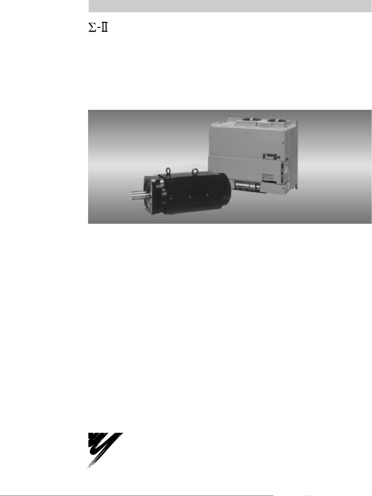
Series SGMBH/SGDH
USER’S MANUAL
AC Servodrive (400 V, 22 to 55 kW)
SGMBH Servomotor
SGDH SERVOPACK
YA S K A WA
MANUAL NO. SIE-S800-32.4
Page 2

Copyright © 2002 YASKAWA ELECTRIC CORPORATION
All rights reserved. No part of this publication may be reproduced, stored in a retrieval system,
or transmitted, in any form, or by any means, mechanical, electronic, photocopying, recording,
or otherwise, without the prior written permission of Yaskawa. No patent liability is assumed
with respect to the use of the information contained herein. Moreover, because Yaskawa is constantly striving to improve its high-quality products, the information contained in this manual is
subject to change without notice. Every precaution has been taken in the preparation of this
manual. Nevertheless, Yaskawa assumes no responsibility for errors or omissions. Neither is
any liability assumed for damages resulting from the use of the information contained in this
publication.
Page 3

About this Manual
This manual provides the following information for the Σ-II Series SGMBH/SGDH
Servodrives.
• Procedures for installing and wiring the servomotor and SERVOPACK.
• Procedures for trial operation of the Servodrive.
• Procedures for using functions and adjusting the servodrives.
• Procedures for using the built-in Panel Operator and the Hand-held Digital Operator.
• Ratings and specifications for standard models.
• Procedures for maintenance and inspection.
Intended Audience
This manual is intended for the following users.
• Those designing Σ-II Series servodrive systems.
• Those installing or wiring Σ-II Series servodrives.
• Those performing trial operation or adjustments of Σ-II Series servodrives.
• Those maintaining or inspecting Σ-II Series servodrives.
Description of Technical Terms
In this manual, the following terms are defined as follows:
• Servomotor = Σ-II Series SGMBH servomotor.
• SERVOPACK = Σ-II Series SGDH SERVOPACK.
• Servodrive = A set including a servomotor and Servo Amplifier.
• Servo System = A servo control system that includes the combination of a servodrive
with a host computer and peripheral devices.
Indication of Reverse Signals
In this manual, the names of reverse signals (ones that are valid when low) are written with a
forward slash (/) before the signal name, as shown in the following example:
• S-ON
• P-CON
= /S-ON
= /P-CON
iii
Page 4
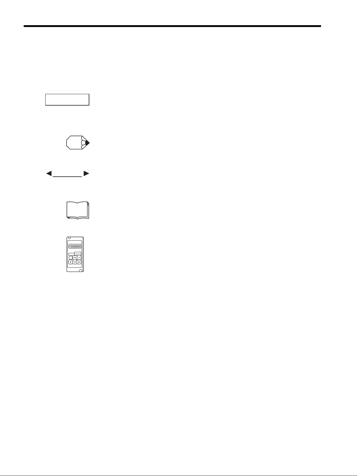
Visual Aids
The following aids are used to indicate certain types of information for easier reference.
IMPORTANT
INFO
EXAMPLE
TERMS
Indicates important information that should be memorized, including precautions such as
alarm displays to avoid damaging the devices.
Indicates supplemental information.
Indicates application examples.
Indicates definitions of difficult terms or terms that have not been previously explained in
this manual.
The text indicated by this icon explains the operating procedure using Hand-held type Digi-
tal Operator (Type: JUSP-OP02A-2).
JUSP-OP02A-2
iv
Page 5
Related Manuals
Refer to the following manuals as required.
Also, keep this manual in a safe place so that it can be referred to whenever neces-
sary.
Σ Series/Σ-ΙΙ Series
Servopacks Personal
Computer Monitoring
Software Operation Manual
Σ-ΙΙ Series
SGMH/SGDM
Digital Operator
Operation Manual
Safety Information
Manual Name Manual Number Contents
SIE-S800-35 Describes the applications and operation of
software for the Σ Series/Σ-II Series servodrive monitoring devices for use on personal computers.
TOE-S800-34 Provides detailed information on the opera-
tion of the JUSP-OP02A-2 Digital Operator, which is an optional product.
WARNING
CAUTION
PROHIBITED
The following conventions are used to indicate precautions in this manual.
Failure to heed precautions provided in this manual can result in serious or possibly even
fatal injury or damage to the products or to related equipment and systems.
Indicates precautions that, if not heeded, could possibly result in loss of life or seri-
ous injury.
Indicates precautions that, if not heeded, could result in relatively serious or minor
injury, damage to the product, or faulty operation.
Indicates actions that must never be taken.
v
Page 6
Safety Precautions
The following precautions are for checking products upon delivery, installation, wiring,
operation, maintenance and inspections.
Checking Products upon Delivery
CAUTION
• Always use the servomotor and SERVOPACK in one of the specified combinations.
Not doing so may cause fire or malfunction.
Installation
CAUTION
• Never use the products in an environment subject to water, corrosive gases, inflammable gases, or
combustibles.
• Doing so may result in electric shock or fire.
vi
Page 7
Wiring
WARNING
• Connect the ground terminal to electrical codes (ground resistance: 100 Ω or less).
Improper grounding may result in electric shock or fire.
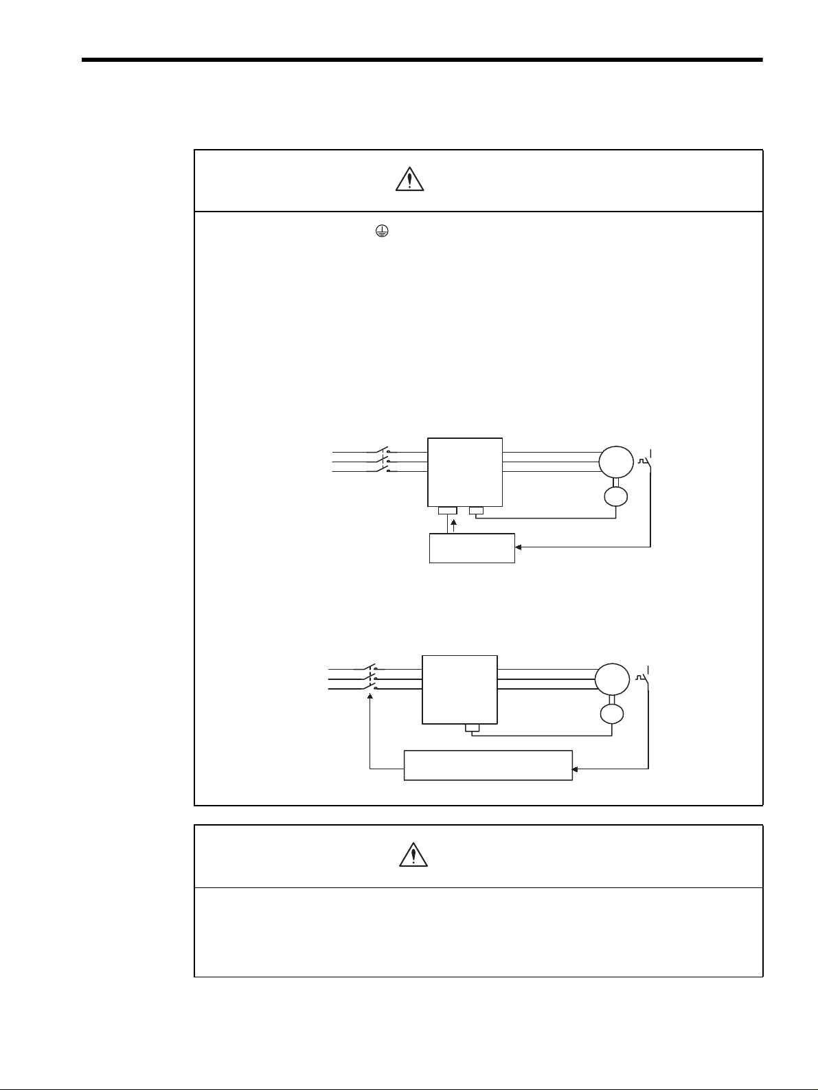
• Use the thermal protector built into the servomotor according to either of the two following meth-
ods.
SGMBH servomotors are cooled by a fan. If the fan is defective or power to the fan is disconnected, heat
from the motor may result in burns or fire.
Method 1:
• Wire the output from the thermal protector to the host controller and turn OFF the servo when the
thermal protector operates.
Maincircuit
contactors
Maincircuit
powersupply
SGDH
SERVOPACK
M
PG
Thermal
protector
ServoOFF
HostController
Method 2:
• Wire the thermal protector to the operating circuit of the main circuit contactors or the host control-
ler and turn OFF the main circuit when the thermal protector operates.
Main
circuit
contactors
Maincircuit
powersupply
Tomaincircuit
contactors
SGDH
SERVOPACK
Hostcontrolleroroperating
circuitofmaincircuitcontactors
M
PG
Thermal
protector
CAUTION
• Do not connect a three-phase power supply to the SERVOPACK’s U, V, or W output terminals.
Doing so may result in injury or fire.
• Securely fasten the power supply terminal screws and motor output terminal screws.
Not doing so may result in fire.
vii
Page 8
Operation
WARNING
• Never touch any rotating motor parts while the motor is running.
Doing so may result in injury.
CAUTION
• Conduct trial operation on the servomotor alone with the motor shaft disconnected from machine to
avoid any unexpected accidents.
Not doing so may result in injury.
• Before starting operation with a machine connected, change the settings to match the parameters
of the machine.
Starting operation without matching the proper settings may cause the machine to run out of control or malfunction.
• Before starting operation with a machine connected, make sure that an emergency stop can be
applied at any time.
Not doing so may result in injury.
• Do not touch the heat sinks during operation.
Doing so may result in burns due to high temperatures.
Maintenance and Inspection
WARNING
• Never touch the inside of the SERVOPACKs.
Doing so may result in electric shock.
• Do not remove the panel cover while the power is ON.
Doing so may result in electric shock.
• Do not touch terminals for five minutes after the power is turned OFF.
Residual voltage may cause electric shock.
CAUTION
• Do not disassemble the servomotor.
Doing so may result in electric shock or injury.
• Do not attempt to change wiring while the power is ON.
Doing so may result in electric shock or injury.
viii
Page 9

General Precautions
Note the following to ensure safe application.
• The drawings presented in this manual are sometimes shown without covers or protective guards. Always
replace the cover or protective guard as specified first, and then operate the products in accordance with
the manual.
• The drawings presented in this manual are typical examples and may not match the product you received.
• This manual is subject to change due to product improvement, specification modification, and manual
improvement. When this manual is revised, the manual code is updated and the new manual is published
as a next edition.
• If the manual must be ordered due to loss or damage, inform your nearest Yaskawa representative or one
of the offices listed on the back of this manual.
• Yaskawa will not take responsibility for the results of unauthorized modifications of this product.
Yaskawa shall not be liable for any damages or troubles resulting from unauthorized modification.
SGDH SERVOPACK Standards and Certification
SGDH SERVOPACKs conform to the following standards. However, because this product is
a built-in type, reconfirmation is required after being installed in the final product.
• EN55011 group 1 class A
• EN50082-2
ix
Page 10

CONTENTS
1 For First-time Users of AC Servos
1.1 Basic Understanding of AC Servos - - - - - - - - - - - - - - - - - - 1-2
1.1.1 Servo Mechanisms - - - - - - - - - - - - - - - - - - - - - - - - - - - - - - - - - - - - 1-2
1.1.2 Technical Terms- - - - - - - - - - - - - - - - - - - - - - - - - - - - - - - - - - - - - - - 1-4
1.2 Configuration of Servo System - - - - - - - - - - - - - - - - - - - - - 1-5
1.3 Features of
1.3.1 Outline - - - - - - - - - - - - - - - - - - - - - - - - - - - - - - - - - - - - - - - - - - - - 1-10
1.3.2 Using the SGDH SERVOPACK - - - - - - - - - - - - - - - - - - - - - - - - - - - 1-11
Σ-ΙΙ Series Servos - - - - - - - - - - - - - - - - - - - - - 1-10
2 Basic Operation
2.1 Precautions - - - - - - - - - - - - - - - - - - - - - - - - - - - - - - - - - - - 2-2
2.2 Installation - - - - - - - - - - - - - - - - - - - - - - - - - - - - - - - - - - - - 2-5
2.2.1 Checking on Delivery - - - - - - - - - - - - - - - - - - - - - - - - - - - - - - - - - - - 2-5
2.2.2 Installing the Servomotor - - - - - - - - - - - - - - - - - - - - - - - - - - - - - - - - 2-7
2.2.3 Allowable Radial and Thrust Loads - - - - - - - - - - - - - - - - - - - - - - - - 2-10
2.2.4 Installing the SERVOPACK - - - - - - - - - - - - - - - - - - - - - - - - - - - - - - 2-11
2.2.5 Power Loss - - - - - - - - - - - - - - - - - - - - - - - - - - - - - - - - - - - - - - - - - 2-13
2.3 Connection and Wiring - - - - - - - - - - - - - - - - - - - - - - - - - - 2-14
2.3.1 Connecting to Peripheral Devices - - - - - - - - - - - - - - - - - - - - - - - - - 2-14
2.3.2 Main Circuit Wiring and Power ON Sequence- - - - - - - - - - - - - - - - - 2-18
2.4 I/O Signals- - - - - - - - - - - - - - - - - - - - - - - - - - - - - - - - - - - 2-21
2.4.1 Examples of I/O Signal Connections - - - - - - - - - - - - - - - - - - - - - - - 2-22
2.4.2 List of CN1 Terminals - - - - - - - - - - - - - - - - - - - - - - - - - - - - - - - - - - 2-23
2.4.3 I/O Signal Names and Functions - - - - - - - - - - - - - - - - - - - - - - - - - - 2-24
2.4.4 Interface Circuits - - - - - - - - - - - - - - - - - - - - - - - - - - - - - - - - - - - - - 2-26
2.5 Wiring Encoders- - - - - - - - - - - - - - - - - - - - - - - - - - - - - - - 2-30
2.5.1 Connecting an Encoder (CN2) and Output Signals
from the SERVOPACK (CN1) - - - - - - - - - - - - - - - - - - - - - - - - - - - - 2-30
2.5.2 Terminal Layout and Types of CN2 Encoder Connector- - - - - - - - - - 2-31
2.5.3 Examples of Connecting I/O Signal Terminals- - - - - - - - - - - - - - - - - 2-32
3 Trial Operation
3.1 Two-step Trial Operation - - - - - - - - - - - - - - - - - - - - - - - - - - 3-2
3.1.1 Step 1: Trial Operation for Servomotor without Load - - - - - - - - - - - - - 3-3
3.1.2 Step 2: Trial Operation with the Servomotor Connected
to the Machine - - - - - - - - - - - - - - - - - - - - - - - - - - - - - - - - 3-9
x
Page 11

3.2 Supplementary Information on Trial Operation - - - - - - - - - 3-10
3.2.1 Servomotors with Brakes - - - - - - - - - - - - - - - - - - - - - - - - - - - - - - - 3-10
3.2.2 Position Control by Host Controller- - - - - - - - - - - - - - - - - - - - - - - - - 3-11
3.3 Minimum Parameters and Input Signals - - - - - - - - - - - - - - 3-12
3.3.1 Parameters - - - - - - - - - - - - - - - - - - - - - - - - - - - - - - - - - - - - - - - - -3-12
3.3.2 Input Signals - - - - - - - - - - - - - - - - - - - - - - - - - - - - - - - - - - - - - - - -3-13
4 Parameter Settings and Functions
4.1 Settings According to Device Characteristics - - - - - - - - - - - 4-4
4.1.1 Switching Servomotor Rotation Direction - - - - - - - - - - - - - - - - - - - - -4-4
4.1.2 Setting the Overtravel Limit Function - - - - - - - - - - - - - - - - - - - - - - - -4-5
4.1.3 Limiting Torques - - - - - - - - - - - - - - - - - - - - - - - - - - - - - - - - - - - - - - -4-9
4.2 Settings According to Host Controller - - - - - - - - - - - - - - - - 4-14
4.2.1 Speed Reference - - - - - - - - - - - - - - - - - - - - - - - - - - - - - - - - - - - - -4-14
4.2.2 Position Reference - - - - - - - - - - - - - - - - - - - - - - - - - - - - - - - - - - - -4-16
4.2.3 Using the Encoder Signal Output - - - - - - - - - - - - - - - - - - - - - - - - - -4-22
4.2.4 Sequence I/O Signals - - - - - - - - - - - - - - - - - - - - - - - - - - - - - - - - - - 4-26
4.2.5 Using the Electronic Gear Function - - - - - - - - - - - - - - - - - - - - - - - - 4-29
4.2.6 Contact Input Speed Control - - - - - - - - - - - - - - - - - - - - - - - - - - - - -4-33
4.2.7 Using Torque Control - - - - - - - - - - - - - - - - - - - - - - - - - - - - - - - - - - 4-38
4.2.8 Torque Feed-forward Function - - - - - - - - - - - - - - - - - - - - - - - - - - - - 4-44
4.2.9 Speed Feed-forward Function - - - - - - - - - - - - - - - - - - - - - - - - - - - -4-46
4.2.10 Torque Limiting by Analog Voltage Reference, Function 1- - - - - - - -4-47
4.2.11 Torque Limiting by Analog Voltage Reference, Function 2- - - - - - - - 4-48
4.2.12 Reference Pulse Inhibit Function (INHIBIT) - - - - - - - - - - - - - - - - - -4-50
4.3 Setting Up the SERVOPACK - - - - - - - - - - - - - - - - - - - - - - 4-52
4.3.1 Parameters - - - - - - - - - - - - - - - - - - - - - - - - - - - - - - - - - - - - - - - - -4-52
4.3.2 JOG Speed - - - - - - - - - - - - - - - - - - - - - - - - - - - - - - - - - - - - - - - - -4-53
4.3.3 Input Circuit Signal Allocation - - - - - - - - - - - - - - - - - - - - - - - - - - - -4-53
4.3.4 Output Circuit Signal Allocation - - - - - - - - - - - - - - - - - - - - - - - - - - -4-57
4.3.5 Control Mode Selection - - - - - - - - - - - - - - - - - - - - - - - - - - - - - - - - - 4-59
4.4 Setting Stop Functions - - - - - - - - - - - - - - - - - - - - - - - - - - 4-62
4.4.1 Adjusting Offset - - - - - - - - - - - - - - - - - - - - - - - - - - - - - - - - - - - - - -4-62
4.4.2 Using the Dynamic Brake - - - - - - - - - - - - - - - - - - - - - - - - - - - - - - -4-63
4.4.3 Using the Zero Clamp Function - - - - - - - - - - - - - - - - - - - - - - - - - - -4-64
4.4.4 Using the Holding Brake - - - - - - - - - - - - - - - - - - - - - - - - - - - - - - - -4-66
4.5 Forming a Protective Sequence- - - - - - - - - - - - - - - - - - - - 4-70
4.5.1 Using Servo Alarm and Alarm Code Outputs- - - - - - - - - - - - - - - - - -4-70
4.5.2 Using the Servo ON Input Signal - - - - - - - - - - - - - - - - - - - - - - - - - -4-72
4.5.3 Using the Positioning Completed Output Signal - - - - - - - - - - - - - - - - 4-73
4.5.4 Speed Coincidence Output - - - - - - - - - - - - - - - - - - - - - - - - - - - - - -4-75
4.5.5 Using the Running Output Signal - - - - - - - - - - - - - - - - - - - - - - - - - - 4-76
xi
Page 12

4.5.6 Using the Servo Ready Output Signal - - - - - - - - - - - - - - - - - - - - - - 4-77
4.5.7 Using the Warning Output Signal- - - - - - - - - - - - - - - - - - - - - - - - - - 4-78
4.5.8 Using the Near Output Signal - - - - - - - - - - - - - - - - - - - - - - - - - - - - 4-80
4.5.9 Handling Power Loss - - - - - - - - - - - - - - - - - - - - - - - - - - - - - - - - - - 4-81
4.6 External Regenerative Resistors - - - - - - - - - - - - - - - - - - - 4-83
4.7 Absolute Encoders - - - - - - - - - - - - - - - - - - - - - - - - - - - - - 4-84
4.7.1 Interface Circuit - - - - - - - - - - - - - - - - - - - - - - - - - - - - - - - - - - - - - - 4-85
4.7.2 Selecting an Absolute Encoder - - - - - - - - - - - - - - - - - - - - - - - - - - - 4-86
4.7.3 Handling Batteries - - - - - - - - - - - - - - - - - - - - - - - - - - - - - - - - - - - - 4-86
4.7.4 Absolute Encoder Setup - - - - - - - - - - - - - - - - - - - - - - - - - - - - - - - - 4-87
4.7.5 Absolute Encoder Reception Sequence - - - - - - - - - - - - - - - - - - - - - 4-90
4.7.6 Multiturn Limit Setting- - - - - - - - - - - - - - - - - - - - - - - - - - - - - - - - - - 4-95
4.8 Special Wiring - - - - - - - - - - - - - - - - - - - - - - - - - - - - - - - - 4-99
4.8.1 Wiring Precautions- - - - - - - - - - - - - - - - - - - - - - - - - - - - - - - - - - - - 4-99
4.8.2 Wiring for Noise Control - - - - - - - - - - - - - - - - - - - - - - - - - - - - - - - 4-101
4.8.3 Using More Than One Servodrive - - - - - - - - - - - - - - - - - - - - - - - - 4-105
4.8.4 Extending Encoder Cables - - - - - - - - - - - - - - - - - - - - - - - - - - - - - 4-106
5 Servo Adjustment
5.1 Smooth Operation - - - - - - - - - - - - - - - - - - - - - - - - - - - - - - 5-2
5.1.1 Using the Soft Start Function- - - - - - - - - - - - - - - - - - - - - - - - - - - - - - 5-2
5.1.2 Smoothing- - - - - - - - - - - - - - - - - - - - - - - - - - - - - - - - - - - - - - - - - - - 5-3
5.1.3 Adjusting Gain - - - - - - - - - - - - - - - - - - - - - - - - - - - - - - - - - - - - - - - - 5-4
5.1.4 Adjusting Offset - - - - - - - - - - - - - - - - - - - - - - - - - - - - - - - - - - - - - - - 5-4
5.1.5 Setting the Torque Reference Filter Time Constant - - - - - - - - - - - - - - 5-5
5.1.6 Notch Filter - - - - - - - - - - - - - - - - - - - - - - - - - - - - - - - - - - - - - - - - - - 5-5
5.2 High-speed Positioning - - - - - - - - - - - - - - - - - - - - - - - - - - - 5-6
5.2.1 Setting Servo Gain- - - - - - - - - - - - - - - - - - - - - - - - - - - - - - - - - - - - - 5-6
5.2.2 Using Feed-forward Control - - - - - - - - - - - - - - - - - - - - - - - - - - - - - - 5-8
5.2.3 Using Proportional Control - - - - - - - - - - - - - - - - - - - - - - - - - - - - - - - 5-8
5.2.4 Setting Speed Bias - - - - - - - - - - - - - - - - - - - - - - - - - - - - - - - - - - - - 5-9
5.2.5 Using Mode Switch - - - - - - - - - - - - - - - - - - - - - - - - - - - - - - - - - - - 5-10
5.2.6 Speed Feedback Compensation - - - - - - - - - - - - - - - - - - - - - - - - - - 5-14
5.3 Autotuning - - - - - - - - - - - - - - - - - - - - - - - - - - - - - - - - - - - 5-16
5.3.1 Online Autotuning - - - - - - - - - - - - - - - - - - - - - - - - - - - - - - - - - - - - 5-17
5.3.2 Machine Rigidity Settings for Online Autotuning - - - - - - - - - - - - - - - 5-19
5.3.3 Saving Results of Online Autotuning - - - - - - - - - - - - - - - - - - - - - - - 5-22
5.3.4 Parameters Related to Online Autotuning- - - - - - - - - - - - - - - - - - - - 5-25
5.4 Servo Gain Adjustments - - - - - - - - - - - - - - - - - - - - - - - - - 5-27
5.4.1 Servo Gain Parameters - - - - - - - - - - - - - - - - - - - - - - - - - - - - - - - - 5-27
5.4.2 Basic Rules of Gain Adjustment - - - - - - - - - - - - - - - - - - - - - - - - - - 5-27
5.4.3 Making Manual Adjustments - - - - - - - - - - - - - - - - - - - - - - - - - - - - - 5-29
xii
Page 13

5.4.4 Gain Setting Reference Values - - - - - - - - - - - - - - - - - - - - - - - - - - -5-34
5.5 Analog Monitor- - - - - - - - - - - - - - - - - - - - - - - - - - - - - - - - 5-36
6 Using the Digital Operator
6.1 Basic Operation - - - - - - - - - - - - - - - - - - - - - - - - - - - - - - - - 6-2
6.1.1 Connecting the Digital Operator - - - - - - - - - - - - - - - - - - - - - - - - - - - -6-2
6.1.2 Functions- - - - - - - - - - - - - - - - - - - - - - - - - - - - - - - - - - - - - - - - - - - -6-3
6.1.3 Resetting Servo Alarms- - - - - - - - - - - - - - - - - - - - - - - - - - - - - - - - - -6-4
6.1.4 Basic Mode Selection - - - - - - - - - - - - - - - - - - - - - - - - - - - - - - - - - - -6-5
6.1.5 Status Display Mode - - - - - - - - - - - - - - - - - - - - - - - - - - - - - - - - - - - -6-6
6.1.6 Operation in Parameter Setting Mode- - - - - - - - - - - - - - - - - - - - - - - -6-9
6.1.7 Operation in Monitor Mode - - - - - - - - - - - - - - - - - - - - - - - - - - - - - - 6-15
6.2 Applied Operation - - - - - - - - - - - - - - - - - - - - - - - - - - - - - 6-20
6.2.1 Operation in Alarm Traceback Mode- - - - - - - - - - - - - - - - - - - - - - - - 6-21
6.2.2 Controlling Operation Through the Digital Operator - - - - - - - - - - - - -6-22
6.2.3 Automatic Adjustment of the Speed and Torque Reference Offset - - - 6-25
6.2.4 Manual Adjustment of the Speed and Torque Reference Offset- - - - - 6-28
6.2.5 Clearing Alarm Traceback Data - - - - - - - - - - - - - - - - - - - - - - - - - - -6-33
6.2.6 Checking the Motor Model- - - - - - - - - - - - - - - - - - - - - - - - - - - - - - -6-35
6.2.7 Checking the Software Version - - - - - - - - - - - - - - - - - - - - - - - - - - - 6-38
6.2.8 Zero-point Search Mode - - - - - - - - - - - - - - - - - - - - - - - - - - - - - - - - 6-39
6.2.9 Initializing Parameter Settings - - - - - - - - - - - - - - - - - - - - - - - - - - - - 6-42
6.2.10 Manual Zero Adjustment and Gain Adjustment of
Analog Monitor Output - - - - - - - - - - - - - - - - - - - - - - - - - - - - - - - - -6-44
6.2.11 Adjusting the Motor Current Detection Offset - - - - - - - - - - - - - - - - - 6-49
6.2.12 Password Setting (Write Prohibited Setting) - - - - - - - - - - - - - - - - -6-53
6.2.13 Clearing Option Unit Detection Results - - - - - - - - - - - - - - - - - - - - -6-55
7 Servo Selection and Data Sheets
7.1 Selecting a S-II Series Servodrives - - - - - - - - - - - - - - - - - - 7-3
7.1.1 Selecting Servomotors - - - - - - - - - - - - - - - - - - - - - - - - - - - - - - - - - -7-3
7.1.2 Selecting SERVOPACKs - - - - - - - - - - - - - - - - - - - - - - - - - - - - - - - - -7-8
7.2 Servomotor Ratings and Specifications - - - - - - - - - - - - - - - 7-9
7.2.1 Ratings and Specifications - - - - - - - - - - - - - - - - - - - - - - - - - - - - - - -7-9
7.2.2 Mechanical Characteristics - - - - - - - - - - - - - - - - - - - - - - - - - - - - - - 7-11
7.3 SERVOPACK Ratings and Specifications - - - - - - - - - - - - 7-13
7.3.1 Combined Specifications - - - - - - - - - - - - - - - - - - - - - - - - - - - - - - - -7-13
7.3.2 Ratings and Specifications - - - - - - - - - - - - - - - - - - - - - - - - - - - - - -7-14
7.3.3 Overload Characteristics - - - - - - - - - - - - - - - - - - - - - - - - - - - - - - - - 7-18
7.3.4 Starting and Stopping Time - - - - - - - - - - - - - - - - - - - - - - - - - - - - - -7-19
7.3.5 Load Moment of Inertia - - - - - - - - - - - - - - - - - - - - - - - - - - - - - - - - -7-19
7.3.6 Overhanging Load - - - - - - - - - - - - - - - - - - - - - - - - - - - - - - - - - - - - 7-20
xiii
Page 14

7.4 Servodrive Dimensional Drawings - - - - - - - - - - - - - - - - - - 7-21
7.4.1 Servomotors - - - - - - - - - - - - - - - - - - - - - - - - - - - - - - - - - - - - - - - - 7-21
7.4.2 SERVOPACKs- - - - - - - - - - - - - - - - - - - - - - - - - - - - - - - - - - - - - - - 7-24
7.5 Specifications and Dimensional Drawings
for Peripheral Devices - - - - - - - - - - - - - - - - - - - - - - - - - - 7-27
7.5.1 Cable Specifications and Peripheral Devices - - - - - - - - - - - - - - - - - 7-27
7.5.2 Digital Operator - - - - - - - - - - - - - - - - - - - - - - - - - - - - - - - - - - - - - - 7-31
7.5.3 CN1 Connector - - - - - - - - - - - - - - - - - - - - - - - - - - - - - - - - - - - - - - 7-32
7.5.4 Connector Terminal Block Converter Unit - - - - - - - - - - - - - - - - - - - - 7-34
7.5.5 Cable With CN1 Connector and One End Without Connector- - - - - - 7-36
7.5.6 CN2 Encoder Connector at SERVOPACK - - - - - - - - - - - - - - - - - - - 7-37
7.5.7 Encoder Cables - - - - - - - - - - - - - - - - - - - - - - - - - - - - - - - - - - - - - - 7-37
7.5.8 Absolute Encoder Battery - - - - - - - - - - - - - - - - - - - - - - - - - - - - - - - 7-41
7.5.9 Brake Power Supplies - - - - - - - - - - - - - - - - - - - - - - - - - - - - - - - - - 7-42
7.5.10 Molded-case Circuit Breaker (MCCB) - - - - - - - - - - - - - - - - - - - - - 7-44
7.5.11 Noise Filter - - - - - - - - - - - - - - - - - - - - - - - - - - - - - - - - - - - - - - - - 7-44
7.5.12 Surge Suppressor - - - - - - - - - - - - - - - - - - - - - - - - - - - - - - - - - - - 7-46
7.5.13 Regenerative Resistor Unit - - - - - - - - - - - - - - - - - - - - - - - - - - - - - 7-46
7.5.14 Dynamic Brake (DB) Unit - - - - - - - - - - - - - - - - - - - - - - - - - - - - - - 7-50
7.5.15 Thermal Relays - - - - - - - - - - - - - - - - - - - - - - - - - - - - - - - - - - - - - 7-56
7.5.16 Variable Resistor for Speed Setting - - - - - - - - - - - - - - - - - - - - - - - 7-59
7.5.17 Encoder Signal Converter Unit - - - - - - - - - - - - - - - - - - - - - - - - - - 7-59
7.5.18 Cables for Connecting PCs to a SERVOPACK - - - - - - - - - - - - - - - 7-61
8 Inspection, Maintenance, and Troubleshooting
8.1 Servodrive Inspection and Maintenance - - - - - - - - - - - - - - 8-2
8.1.1 Servomotor Inspection - - - - - - - - - - - - - - - - - - - - - - - - - - - - - - - - - - 8-2
8.1.2 SERVOPACK Inspection - - - - - - - - - - - - - - - - - - - - - - - - - - - - - - - - 8-3
8.1.3 Replacing Battery for Absolute Encoder - - - - - - - - - - - - - - - - - - - - - - 8-4
8.2 Troubleshooting - - - - - - - - - - - - - - - - - - - - - - - - - - - - - - - - 8-5
8.2.1 Troubleshooting Problems with Alarm Displays- - - - - - - - - - - - - - - - - 8-5
8.2.2 Troubleshooting Problems with No Alarm Display - - - - - - - - - - - - - - 8-35
8.2.3 Alarm Display Table - - - - - - - - - - - - - - - - - - - - - - - - - - - - - - - - - - 8-37
8.2.4 Warning Displays- - - - - - - - - - - - - - - - - - - - - - - - - - - - - - - - - - - - - 8-39
8.2.5 Internal Connection Diagram and Instrument Connection
Examples - - - - - - - - - - - - - - - - - - - - - - - - - - - - - - - - - - - - - - - - - - 8-40
Appendix A List of Parameters
INDEX
xiv
Page 15

1
For First-time Users of AC Servos
This chapter is intended for first–time users of AC servos. It describes the
basic configuration of a servo mechanism and basic technical terms relating to
servos. Users who already have experience in using a servo should also take a
look at this chapter to understand the features of Σ-ΙΙ Series AC Servos.
1.1 Basic Understanding of AC Servos - - - - - - - - - - - - - - - - - - - 1-2
1.1.1 Servo Mechanisms - - - - - - - - - - - - - - - - - - - - - - - - - - - - - - - - - - - - 1-2
1.1.2 Technical Terms - - - - - - - - - - - - - - - - - - - - - - - - - - - - - - - - - - - - - - - 1-4
1.2 Configuration of Servo System - - - - - - - - - - - - - - - - - - - - - - 1-5
1.3 Features of Σ-ΙΙ Series Servos - - - - - - - - - - - - - - - - - - - - - 1-10
1.3.1 Outline - - - - - - - - - - - - - - - - - - - - - - - - - - - - - - - - - - - - - - - - - - - - 1-10
1.3.2 Using the SGDH SERVOPACK - - - - - - - - - - - - - - - - - - - - - - - - - - - 1-11
1
1-1
Page 16

For First-time Users of AC Servos
1
1.1.1 Servo Mechanisms
1.1 Basic Understanding of AC Servos
This section describes the basic configuration of a servo mechanism and technical terms relating
to servos and also explains the features of Σ-ΙΙ Series AC Servos.
1.1.1 Servo Mechanisms
You may be familiar with the following terms:
• Servo
• Servo mechanism
• Servo control system
In fact, these terms are synonymous. They have the following meaning:
A control mechanism that monitors physical quantities such as specified positions.
In short, a servo mechanism is like a servant who does tasks faithfully and quickly according
to his master’s instructions. In fact, “servo” originally derives from the word “servant.”
1
Servo system could be defined in more detail as a mechanism that:
• Moves at a specified speed and
• Locates an object in a specified position
TERMS
1
Servo mechanism
According to Japanese Industrial Standard (JIS) terminology, a “servo mechanism” is defined as a
mechanism that uses the position, direction, or orientation of an object as a process variable to control
a system to follow any changes in a target value (set point). More simply, a servo mechanism is a control mechanism that monitors physical quantities such as specified positions. Feedback control is normally performed by a servo mechanism. (Source: JIS B0181)
1-2
Page 17
1.1 Basic Understanding of AC Servos
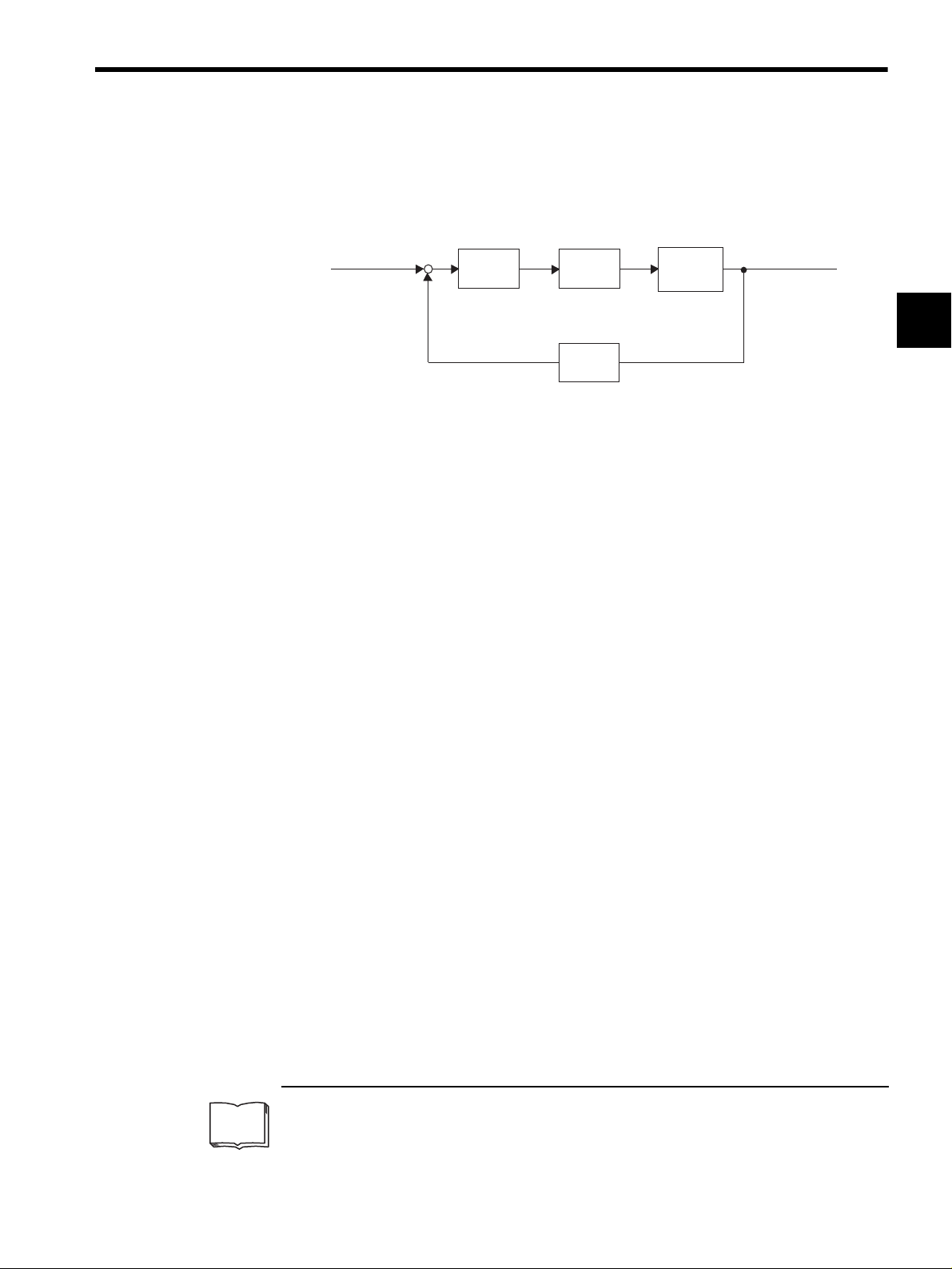
To develop such a servo system, an automatic control system involving feedback control1
must be designed. This automatic control system can be illustrated in the following block
diagram:
ConfigurationofServoSystem
Specifiedposition
input
+
-
Servo
amplifier
Servomotor
Feedbackpart
Detector
Controlled
machine
(load)
Machineposition
output
This servo system is an automatic control system that detects the machine position (output
data), feeds back the data to the input side, compares it with the specified position (input
data), and moves the machine by the difference between the compared data.
In other words, the servo system is a system to control the output data to match the specified
input data.
If, for example, the specified position changes, the servo system will reflect the changes.
In the above example, input data is defined as a position, but input data can be any physical
quantities such as orientation (angle), water pressure, or voltage.
Position, speed, force (torque), electric current, and so on are typical controlled values for a
servo system.
1
TERMS
1
Feedback control
A control method in which process variables are returned to the input side to form a closed loop. It is
also called closed-loop control. If a negative signal is returned to the input side, it is called negative
feedback control. Normally, negative feedback control is used to stabilize the system. If feedback is
not returned, the control method is called open-loop control.
1-3
Page 18
For First-time Users of AC Servos
1
1.1.2 Technical Terms
1.1.2 Technical Terms
The main technical terms used in this manual are as follows:
• Servo mechanism
• Servo
Normally, servo is synonymous with servo mechanism. However, because “mecha-
nism” is omitted, the meaning becomes somewhat ambiguous. Servo may refer to the
entire servo mechanism but may also refer to an integral part of a servo mechanism such
as a servomotor or a servo amplifier. This manual also follows this convention in the use
of the term “servo.”
• Servo control system
Servo control system is almost synonymous with servo mechanism but places the focus
on system control. In this manual, the term “servo system” is also used as a synonym of
servo control system.
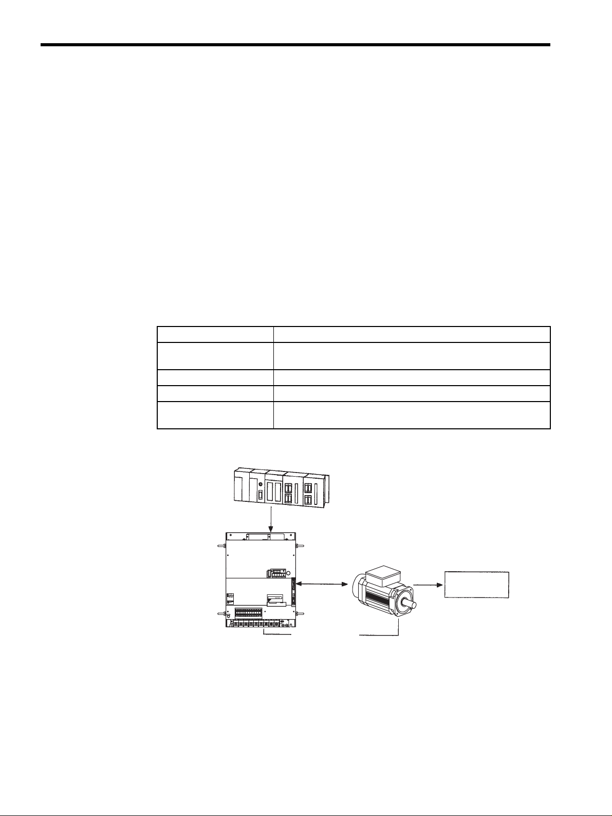
Related Terms Meaning
Servomotor General servomotors or Yaskawa SGMBH servomotors. In some cases,
a position detector (encoder) is included in a servomotor.
SERVOPACK Trademark of Yaskawa servo amplifier “SGDH SERVOPACK.”
Servo drive A servomotor and amplifier pair. Also called “servo.”
Servo system A closed control system consisting of a host controller, servo drive and
controlled system to form a servo mechanism.
Hostcontroller
Reference
Amplifier
POWER
8CN
TDATA/SEEMOD/
CN5
KSERVOPAC
AYASKAW
(SERVOPACK)
O
P
E
R
A
T
O
R
CN3
WARNING
5
!
Maycause
electricshock.
Disconnectallpower
andwait5min.
beforeservicing.
Useproper
groundingtechniques.
480V460
CHARGE
S-HDG
DC
DC
400V0V440
380
DU
DWDV B1
B2
24N
24P
V
V
V
L1/R L2/S
+2-+1
UVW
L3/T
Servomotor
Operate
Controlled
system
Servodrive
Servosystem
1-4
Page 19
1.2 Configuration of Servo System
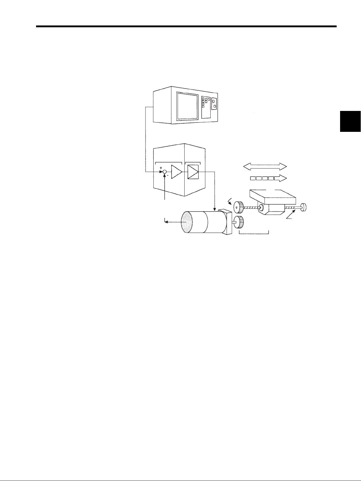
The following diagram illustrates a servo system in detail:
Positionor
speed
reference
Comparator
(Input)
Positionor
speed
feedback
Power
amplifier
(3) (2)
Hostcontroller
(5)
Servoamplifier
(4)
Motor
drive
circuit
Gear
1.2 Configuration of Servo System
(Output)
Position
Speed
(1)
Controlled
system
Movabletable
Ballscrew
1
Drivesystem
(1) Controlled
system:
Detector
servomotor
Mechanical system for which the position or speed is to be controlled. This
includes a drive system that transmits torque from a servomotor.
(2) Servomotor: A main actuator that moves a controlled system. Two types are available: AC ser-
vomotor and DC servomotor.
(3) Detector: A position or speed detector. Normally, an encoder mounted on a motor is used as
a position detector.
(4) Servo amplifier: An amplifier that processes an error signal to correct the difference between a ref-
erence and feedback data and operates the servomotor accordingly. A servo
amplifier consists of a comparator, which processes error signals, and a power
amplifier, which operates the servomotor.
(5) Host controller: A device that controls a servo amplifier by specifying a position or speed as a set
point.
1-5
Page 20
For First-time Users of AC Servos
1
1.1.2 Technical Terms
Servo components (1) to (5) are outlined below:
1. Controlled System
In the previous figure, the controlled system is a movable table for which the position or
speed is controlled. The movable table is driven by a ball screw and is connected to the
servomotor via gears. So, the drive system consists of:
• Gears + Ball Screw
This drive system is most commonly used because the power transmission ratio (gear
ratio) can be freely set to ensure high positioning accuracy. However, play in the gears
must be minimized.
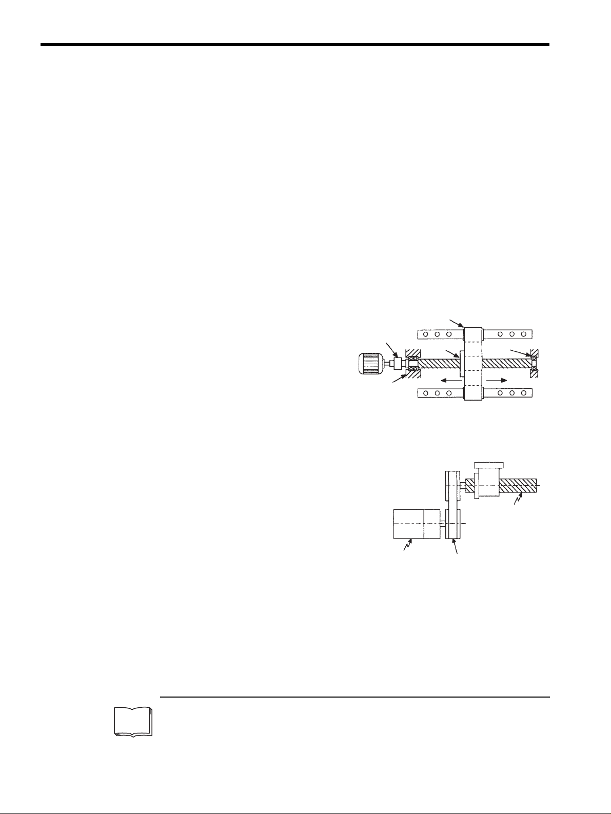
The following drive system
1
is also possible when the controlled system is a movable
table:
• Coupling + Ball Screw
When the power transmission ratio is
1 : 1, a coupling is useful because it
has no play.
This drive system is widely used for
machining tools.
Coupling
Housing
Rolling-contact
guide
Ballscrew
Rolling-contact
bearing
TERMS
• Timing Belt + Trapezoidal Screw Thread
A timing belt is a coupling device that allows
the power transmission ratio to be set freely
and that has no play.
A trapezoidal screw thread does not provide
excellent positioning accuracy, so can be
Trapezoidal
screwthread
treated as a minor coupling device.
To develop an excellent servo system, it is
important to select a rigid drive system that
Servomotor
Timingbelt
has no play.
Configure the controlled system by using an appropriate drive system for the control
purpose.
1
Drive system
Also called a drive mechanism. A drive system connects an actuator (such as a servomotor) to a controlled system and serves a mechanical control component that transmits torque to the controlled system, orientates the controlled system, and converts motion from rotation to linear motion and vice
versa.
1-6
Page 21
1.2 Configuration of Servo System
2. Servomotor
• DC Servomotor and AC Servomotor
Servomotors are divided into two types: DC servomotors and AC servomotors.
DC servomotors are driven by direct current (DC). They have a long history. Up until
the 1980s, the term “servomotor” used to imply a DC servomotor.
From 1984, AC servomotors were emerging as a result of rapid progress in micropro-
cessor technology. Driven by alternating current (AC), AC servomotors are now widely
used because of the following advantages:
• Easy maintenance: No brush
• High speed: No limitation in rectification rate
Note however that servomotors and SERVOPACKs use some parts that are subject to
mechanical wear or aging. For preventive maintenance, inspect and replace parts at reg-
ular intervals. For details, refer to Chapter 8 Inspection, Maintenance, and Trouble-
shooting.
• AC Servomotor
1
AC servomotors are divided into two types: Synchronous type and induction type. The
synchronous type is more commonly used.
For a synchronous type servomotor, motor speed is controlled by changing the fre-
quency of alternating current.
A synchronous type servomotor provides strong holding torque when stopped, so this
type is ideal when precise positioning is required. Use this type for a servo mechanism
for position control.
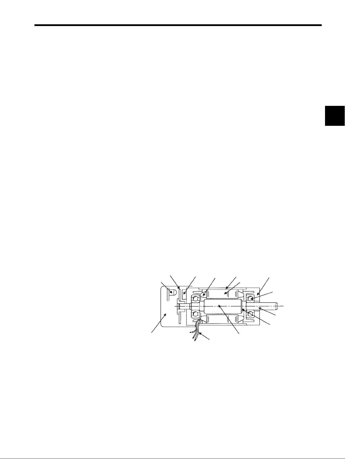
The following figure illustrates the structure of a synchronous type servomotor:
Rotary disc
Light-emitting
element
Position detector
(encoder)
Light-receiving
element
Armature
wire
Lead wire
Housing
Stator core
Magnet
Front cap
Ball bearing
Shaft
Rotor core
Yaskawa SGMBH servomotors are of the synchronous type.
• Performance of Servomotor
A servomotor must have “instantaneous power” so that it can start as soon as a start ref-
erence is received. The term “power rating (kW/s)” is used to represent instantaneous
power. It refers to the electric power (kW) that a servomotor generates per second. The
greater the power rating, the more powerful the servomotor.
1-7
Page 22
For First-time Users of AC Servos
1
3. Detector
A servo system requires a position or speed detector. It uses an encoder mounted on a
servomotor for this purpose. Encoders are divided into the following two types:
• Incremental Encoder
An incremental encoder is a pulse generator, which generates a certain number of pulses
per revolution (e.g., 2,000 pulses per revolution). If this encoder is connected to the
mechanical system and one pulse is defined as a certain length (e.g., 0.001 mm), it can
be used as a position detector. However, this encoder does not detect an absolute posi-
tion and merely outputs a pulse train. Hence zero point return operation must be per-
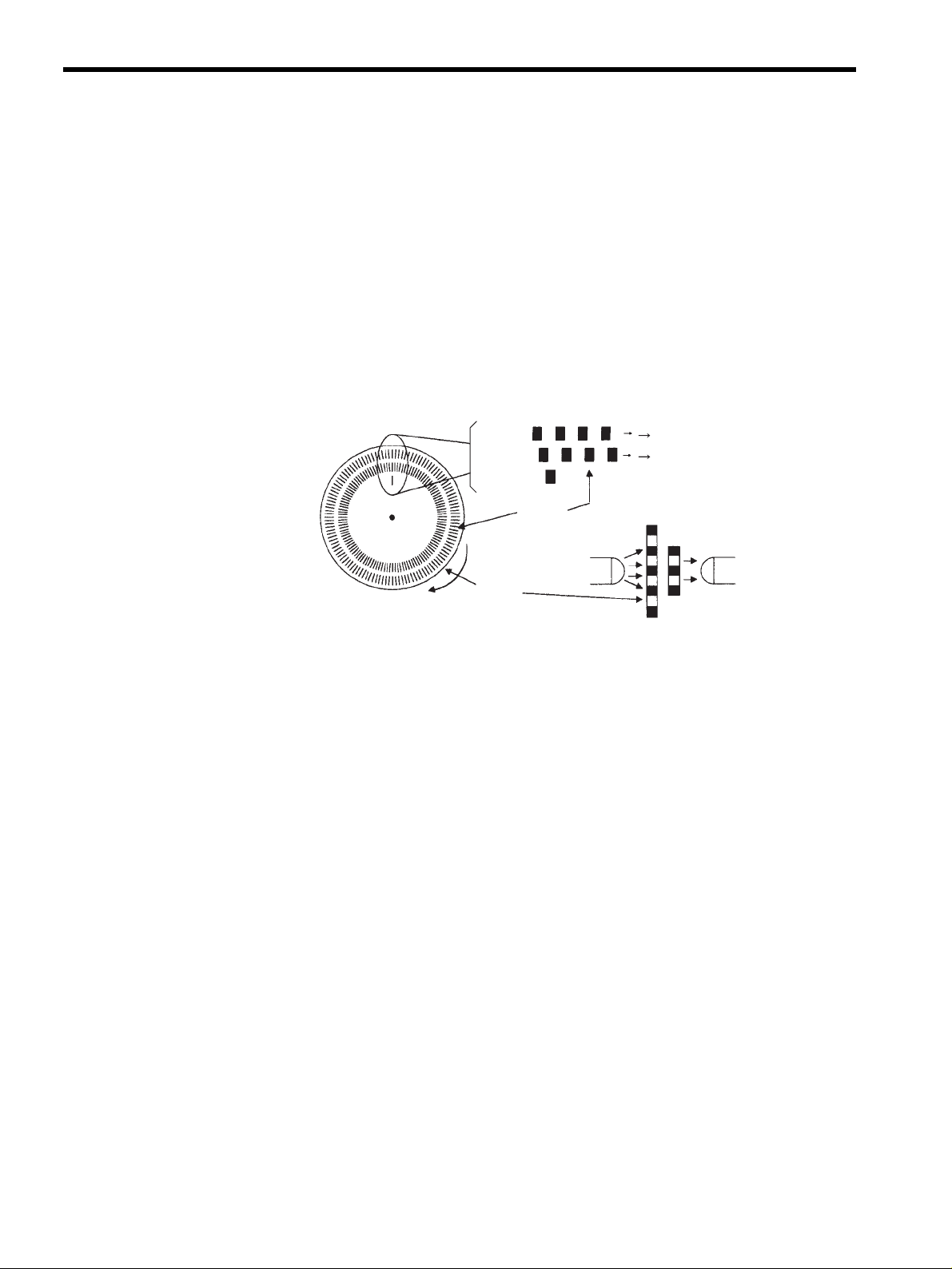
formed before positioning. The following figure illustrates the operation principle of a
pulse generator:
Phase A pulse train
Phase B pulse train
Fixed slit
Light-receiving
element
Center of
revolution
Phase A
Phase B
Phase Z
Rotary
disc
Slit
Light-emitting
element
Rotary slit
• Absolute Encoder
An absolute encoder is designed to detect an absolute angle of rotation as well as to per-
form the general functions of an incremental encoder. With an absolute encoder, there-
fore, it is possible to create a system that does not require zero point return operation at
the beginning of each operation.
• Difference between an Absolute and Incremental Encoder
An absolute encoder will keep track of the motor shaft position even if system power is
lost and some motion occurs during that period of time. The incremental encoder is
incapable of the above.
1-8
Page 23
1.2 Configuration of Servo System
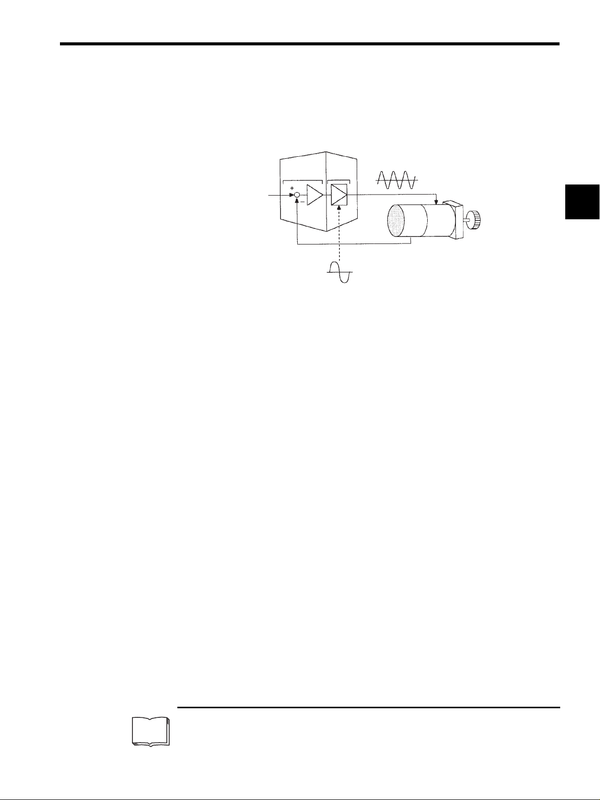
4. Servo Amplifier
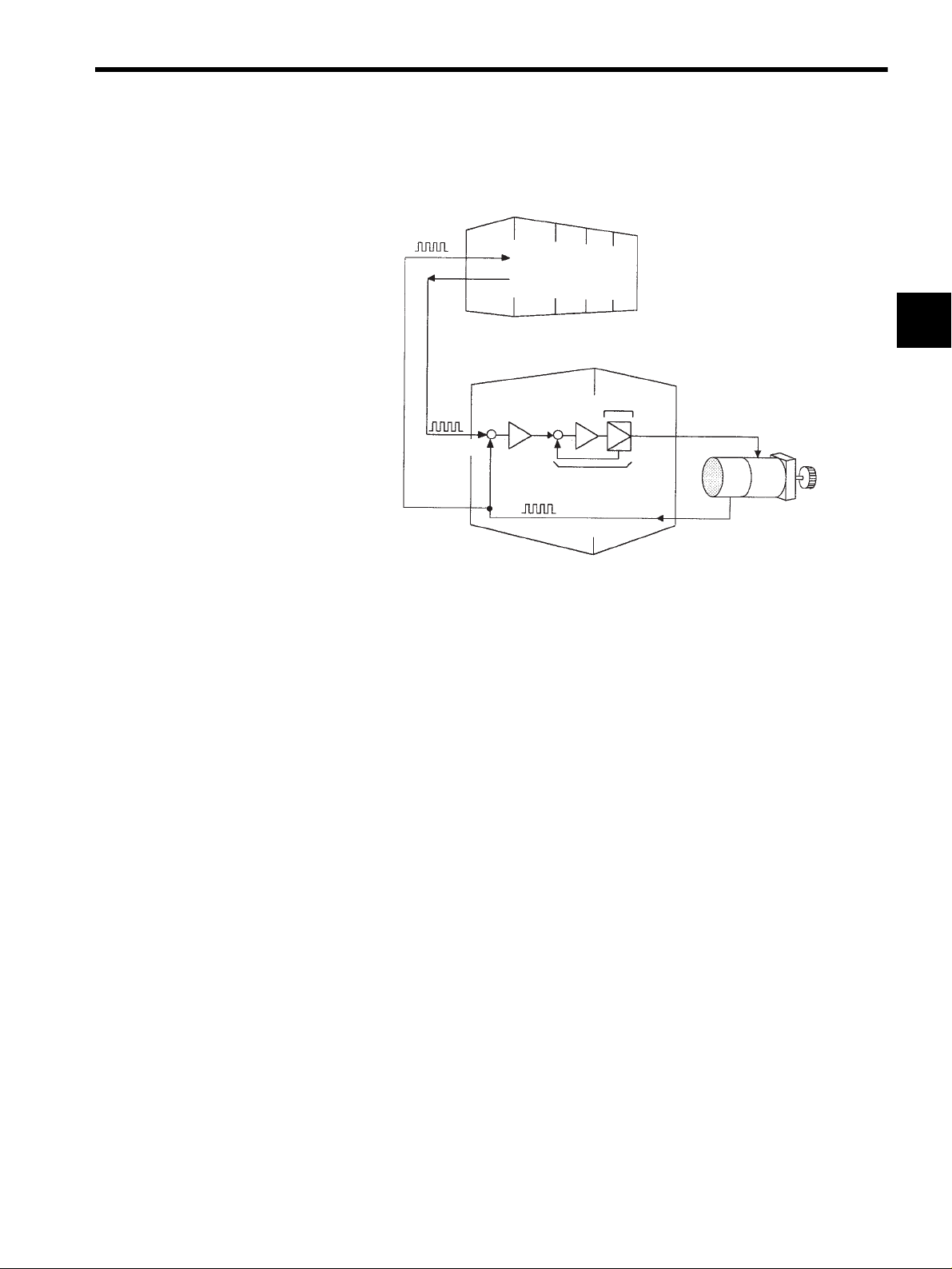
A servo amplifier is required to operate an AC servomotor. The following figure illus-
trates the configuration of a servo amplifier:
Servo amplifier
Motor driving AC power
Reference
input
Comparator
Power
amplifier
1
Feedback
Commercial AC power
Servomotor
A servo amplifier consists of the following two sections:
• Comparator
A comparator consists of a comparison function and a control function. The comparison
function compares reference input (position or speed) with a feedback signal and gener-
ates a differential signal.
The control function amplifies and transforms the differential signal. In other words, it
performs proportional (P) control or proportional/integral (PI) control
1
. (It is not impor-
tant if you do not understand these control terms completely at this point.)
• Power Amplifier
A power amplifier runs the servomotor at a speed or torque proportional to the output of
the comparator. In other words, from the commercial power supply of 50/60 Hz, it gen-
erates alternating current with a frequency proportional to the reference speed and runs
the servomotor with this current.
5. Host Controller
A host controller controls a servo amplifier by specifying a position or speed as a set
point.
TERMS
For speed reference, a position control loop may be formed in the host controller when a
position feedback signal is received. Yaskawa machine controller MP920 is a typical
host controller.
1
Proportional/integral (PI) control
PI control provides more accurate position or speed control than proportional control, which is more
commonly used.
1-9
Page 24
For First-time Users of AC Servos
1
1.3.1 Outline
1.3 Features of Σ-ΙΙ Series Servos
A Σ-ΙΙ Series Servo consists of an SGMBH servomotor and an SGDH SERVOPACK.
1.3.1 Outline
This section outlines SGMBH servomotor types and the control types of SGDH SERVO-
PAC Ks .
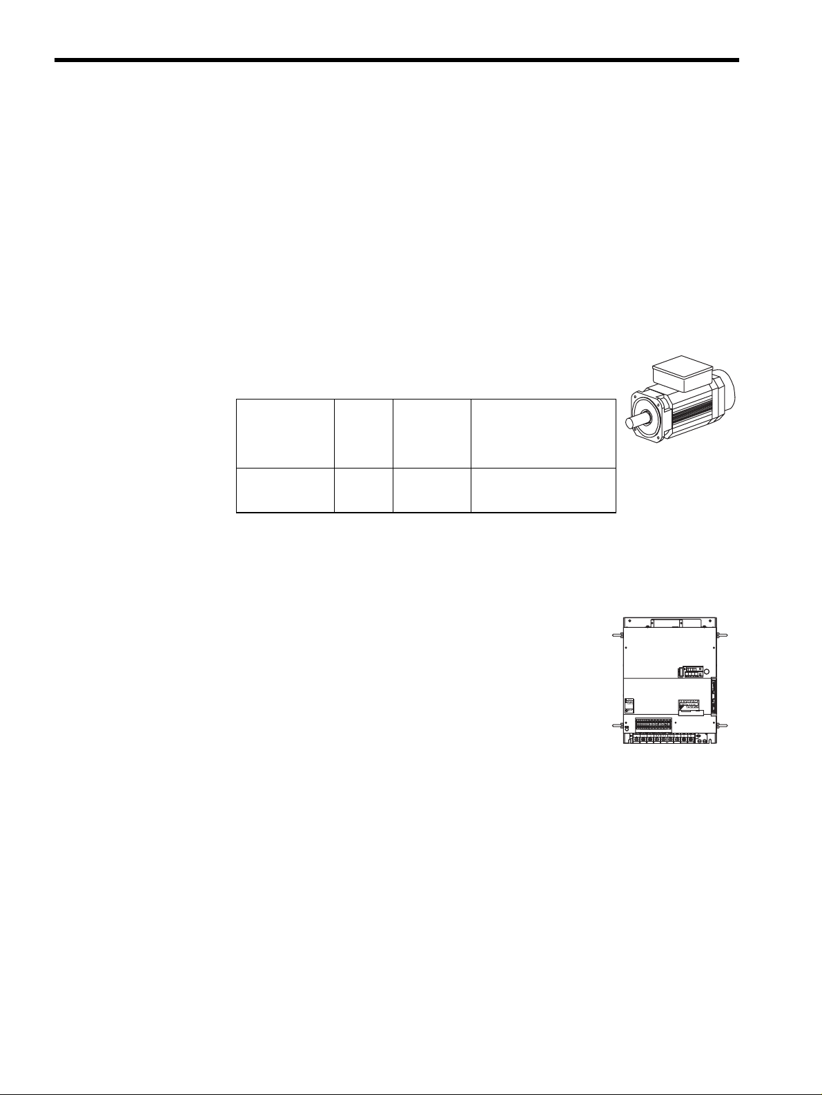
SGMBH Servomotor Type
Σ-ΙΙ Series SGMBH servomotors are synchronous type servomo-
tors and have the following features:
Rated Motor
Speed
Voltage Maximum
To rq u e
Rated Output
Maximum
Motor Speed
1500 min
2000 min
-1
-1
400 V 200 % 22 to 55 kW (10 models)
Control Types of SGDH SERVOPACK
SGDH SERVOPACKs allow the control of speed, position and torque.
Speed Control (Analog Reference)
Accepts an analog voltage speed reference.
Position Control (Pulse Reference)
Accepts a pulse train position reference.
Torque Control (Analog Reference)
Accepts an analog voltage torque reference.
SGMBH
Servomotor
WARNING
5
May cause
electric shock.
Disconnect all power
and wait 5 min.
before servicing.
Use proper
grounding techniques.
SGDH SERVOPACK
1-10
Page 25
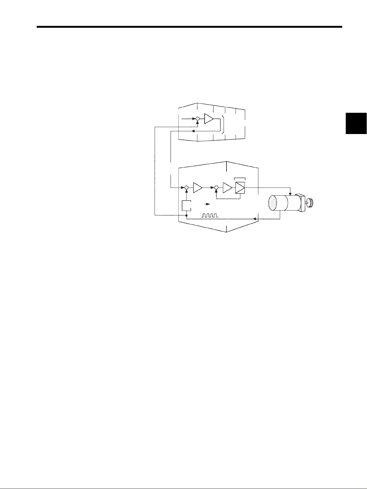
1.3.2 Using the SGDH SERVOPACK
Using the SERVOPACK for Speed Control
The most common use of a SERVOPACK for speed control is shown below:
1.3 Features of Σ-ΙΙ Series Servos
Host controller
Position reference
Position
feedback
(Analog
voltage)
+
Speed
reference
+
-
Position
-
Convert
Position feedback
Position control loop
SERVOPACK
(speed control mode)
Power
amplifier
+
-
Speed
Pulse train
Servomotor
Torque
(current)
feedback
Encoder
As shown in the above figure, a position control loop is formed in the host controller. The
host controller compares a position reference with a position feedback signal and sends the
processed result to the SERVOPACK as a speed reference.
In this way the host controller can be freed from performing the servo mechanism control.
The SERVOPACK undertakes the speed control loop and subsequent control processing.
1
The Yaskawa machine controller MP920 is used as a typical host controller.
1-11
Page 26
For First-time Users of AC Servos
1
1.3.2 Using the SGDH SERVOPACK
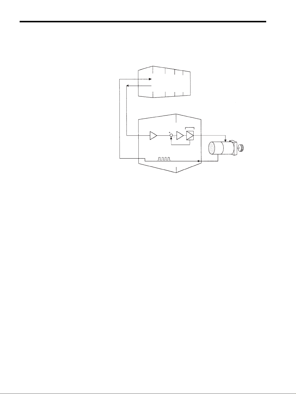
Using the SERVOPACK for Torque Control
The SERVOPACK can be used for torque control as shown below.
Host controller
Position
monitoring
Position
information
Torque
reference
(Analog
voltage)
Position feedback Encoder
SERVOPACK
(torque control mode)
Power
amplifier
Servomotor
Torque (current)
feedback
Pulse train
The host controller outputs a torque reference to control the SERVOPACK. It also receives a
pulse train (position information) from the SERVOPACK and uses it to monitor the position.
1-12
Page 27
Using the SERVOPACK for Position Control
The SERVOPACK can be used for position control as shown below.
Host controller
Position
monitoring
1.3 Features of Σ-ΙΙ Series Servos
Position
information
Position
reference
Pulse
train
+
+
--
Speed/current loop
Position feedback
SERVOPACK
(position control mode)
Power
amplifier
Servomotor
Pulse train
Encoder
The host controller can send a position reference (pulse train) to the SERVOPACK to per-
form positioning or interpolation. This type of SERVOPACK contains a position control
loop.
Parameters can be used to select either of the following pulse trains:
• Sign + pulse train
• Two-phase pulse train with 90° phase difference
• Forward and reverse pulse trains
The host controller receives a pulse train (position information) from the SERVOPACK and
uses it to monitor the position.
1
Parameter Setting
A Digital Operator can be used to set parameters for a SERVOPACK as follows:
• Setting parameters to enable or disable each function
• Setting parameters required for functions to be used
Set parameters according to the servo system to be set up.
1-13
Page 28

2
Basic Operation
This chapter describes the first things to do when Σ-II Series products are
delivered. It also explains the most fundamental ways of connecting and oper-
ating Σ-II Series products. Both first-time and experienced servo users must
read this chapter.
2.1 Precautions - - - - - - - - - - - - - - - - - - - - - - - - - - - - - - - - - - -2-2
2.2 Installation - - - - - - - - - - - - - - - - - - - - - - - - - - - - - - - - - - - -2-5
2.2.1 Checking on Delivery - - - - - - - - - - - - - - - - - - - - - - - - - - - - - - - - - - - 2-5
2.2.2 Installing the Servomotor - - - - - - - - - - - - - - - - - - - - - - - - - - - - - - - - 2-7
2.2.3 Allowable Radial and Thrust Loads - - - - - - - - - - - - - - - - - - - - - - - - 2-10
2.2.4 Installing the SERVOPACK - - - - - - - - - - - - - - - - - - - - - - - - - - - - - - 2-11
2.2.5 Power Loss - - - - - - - - - - - - - - - - - - - - - - - - - - - - - - - - - - - - - - - - - 2-13
2
2.3 Connection and Wiring - - - - - - - - - - - - - - - - - - - - - - - - - - 2-14
2.3.1 Connecting to Peripheral Devices - - - - - - - - - - - - - - - - - - - - - - - - - 2-14
2.3.2 Main Circuit Wiring and Power ON Sequence - - - - - - - - - - - - - - - - - 2-18
2.4 I/O Signals - - - - - - - - - - - - - - - - - - - - - - - - - - - - - - - - - - - 2-21
2.4.1 Examples of I/O Signal Connections - - - - - - - - - - - - - - - - - - - - - - - 2-22
2.4.2 List of CN1 Terminals - - - - - - - - - - - - - - - - - - - - - - - - - - - - - - - - - - 2-23
2.4.3 I/O Signal Names and Functions - - - - - - - - - - - - - - - - - - - - - - - - - - 2-24
2.4.4 Interface Circuits - - - - - - - - - - - - - - - - - - - - - - - - - - - - - - - - - - - - - 2-26
2.5 Wiring Encoders - - - - - - - - - - - - - - - - - - - - - - - - - - - - - - - 2-30
2.5.1Connecting an Encoder (CN2) and Output Signals
from the SERVOPACK (CN1) - - - - - - - - - - - - - - - - - - - - - - - - - - - - 2-30
2.5.2 Terminal Layout and Types of CN2 Encoder Connector - - - - - - - - - - 2-31
2.5.3 Examples of Connecting I/O Signal Terminals - - - - - - - - - - - - - - - - 2-32
2-1
Page 29
Basic Operation
2
2.1 Precautions
This section provides notes on using Σ-II Series products.
Use a 400-VAC power supply.
Use a 400-VAC power supply.
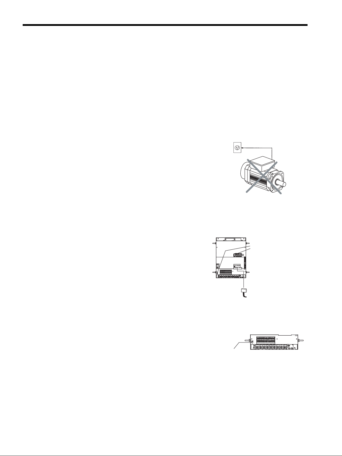
Do not connect the servomotor directly to a commercial power line.
Direct connection to the power frequency sup-
ply will damage the servomotor. The servomo-
tor cannot be operated without an SGDH
SERVOPACK.
power supply
Do not change wiring when power is ON.
Always turn the power OFF before connecting
or disconnecting a connector. (Except for Digi-
tal Operator (Model: JUSP-OP02A-2))
400 VAC
WARNING
5
!
May cause
electric shock.
Disconnect all power
and wait 5 min.
before servicing.
Use proper
grounding techniques.
480 V460
400 V 0 V440
380
V
V
V
CHARGE
Direct
connection
Damage will result!
OFF
POWER
8CN
TDATA/SEEMOD/
CN5
KSERVOPAC
AYASKAW
(POWER and
CHANGE lamp)
O
P
E
R
A
T
O
R
CN3
S-HDG
DC
DC
DU
DWDV B1
B2
24N
24P
L1/R L2/S
+2-+1
UVW
L3/T
Always turn the
power OFF before
connecting a
connector.
Before inspecting, always wait 5 minutes after turning power OFF.
Even after the power is turned OFF, residual
electric charge still remains in the capacitor
inside the SERVOPACK. To prevent an electric
shock, always wait for the CHARGE lamp to go
OFF before starting inspection (if necessary).
2-2
CHARGE lamp
Page 30
Always follow the specified installation method.
2.1 Precautions
When installing SERVOPACKs side by side as
Provide sufficient clearance
shown in the figure on the right, allow at least 10
mm (0.39 in) between and at least 50 mm (1.97 in)
above and below each SERVOPACK. The SERVO-
50 mm
or more
PACK generates heat. Install the SERVOPACK so
that it can radiate heat freely. Note also that the
SERVOPACK must be in an environment free from
condensation, vibration and shock.
Ambient temperature: 0 to 55°C
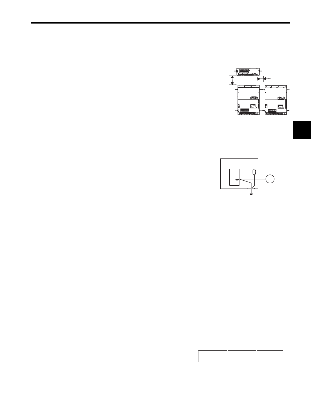
Perform noise reduction and grounding properly.
If the signal line is noisy, vibration or malfunction will result.
• Separate high-voltage cables from low-voltage
cables.
• Use cables as short as possible.
• Perform the grounding with the ground resis-
tance of 100 Ω or less for the servomotor and
SERVOPACK.
• Never use a line filter for the power supply in
the motor circuit.
SERVOPACK
480 V460
400 V 0 V440
380
DU
V
V
V
CHARGE
+2-+1
WARNING
5
!
May cause
electric shock.
Disconnect all power
and wait 5 min.
before servicing.
Use proper
grounding techniques.
480 V460
400 V 0 V440
380
V
V
V
CHARGE
Casing
Single
line
DC
DC
DWDV B1
B2
24N
24P
L1/R L2/S
UVW
L3/T
POWER
8CN
O
P
E
R
A
T
O
R
T DATA/SEEMOD/
CN5
CN3
KSERVOPAC
S-HDG
AYASKAW
DC
DC
DU
DWDV B1
B2
24N
24P
L1/R L2/S
+2-+1
UVW
L3/T
Servomotor
Ground
(with resistance
of 100 Ω or less)
10 mm
or more
WARNING
5
!
May cause
electric shock.
Disconnect all power
and wait 5 min.
before servicing.
Use proper
grounding techniques.
480 V460
400 V 0 V440
380
DU
V
V
V
CHARGE
+2-+1
M
POWER
8CN
O
P
E
R
A
T
O
R
TDATA/SEEMOD/
CN5
CN3
KSERVOPAC
S-HDG
AYASKAW
DC
DC
DWDV B1
B2
24N
24P
L1/R L2/S
UVW
L3/T
2
Conduct a voltage resistance test under the following conditions.
• Voltage: 1500 Vrms AC, one minute
• Current limit: 100 mA
• Frequency: 50/60 Hz
• Voltage application points: Between 480 V, 460 V, 440 V, 400 V, 380 V, 0 V terminals,
L1/R, L2/S, L3/T terminals, and frame ground (connect terminals securely).
Contact your Yaskawa representative before applying voltage to points not specified above,
e.g., when performing standards certification tests.
Use a fast-response type ground-fault interrupter.
For a ground-fault interrupter, always use a
fast-response type or one designed for PWM
inverters. Do not use a time-delay type.
GOOD
Fast-response
type
Ground-fault interrupter
GOOD
For PWM
inverter
POOR
Time-delay
type
2-3
Page 31

Basic Operation
2
Do not perform continuous operation under overhanging load.
Continuous operation cannot be performed
by rotating the motor from the load and
applying regenerative braking. Regenerative
braking by the SERVOPACK can be applied
only for a short period, such as the motor
deceleration time.
The servomotor cannot be oper-
ated by turning the power ON and OFF.
Frequently turning the power ON and OFF
causes the internal circuit elements to deteri-
orate. Always start or stop the servomotor by
using reference pulses.
Do not apply regenerative
braking continuously.
Powe r
supply
Do not start or stop by
tuning power ON and OFF.
Servomotor
SERVOPACK
380 to 480 V
0V
L1/R
L2/S
L3/T
2-4
Page 32

2.2 Installation
This section describes how to check Σ-II Series products on delivery and how to install them.
2.2.1 Checking on Delivery
Check the following items when Σ-II Series products are delivered.
Check Items Comments
Are the delivered products the ones
that were ordered?
Does the servomotor shaft rotate
smoothly?
Is there any damage? Check the overall appearance, and check for damage or scratches
Are there any loose screws? Check screws for looseness using a screwdriver.
2.2 Installation
Check the model numbers marked on the nameplates of the servomotor and SERVOPACK. (See the following.)
The servomotor shaft is normal if it can be turned smoothly by
hand. Servomotors with brakes, however, cannot be turned manually.
that may have occurred during shipping.
2
If any of the above items are faulty or incorrect, contact your Yaskawa sales representative
or the dealer from whom you purchased the products.
Servomotors
External Appearance and Nameplate Examples
(Example)
Rated output
Servomotor model
AC SERVO MOTOR
SGMBH - 2BDCA
SGMBH
servomotor
TYPE
kw N.m
22
-1
min
1500
RATING
CONT.
SER.NO.
DATE
9708
YASKAWA ELECTRIC CORPORATION
140
A
58
K7A500 101 - 004
Munufacturing date
Serial number
Rated rotation speed
ENCODER
UTMAH- B12BDYR11
17 bit
JAPAN
2-5
Page 33

Basic Operation
2
2.2.1 Checking on Delivery
Model Numbers
SGMBH -2BD C A
Σ-II Series
Servomotor
Servomotor Capacity
2B: 22 kW 4E: 45 kW
3Z: 30 kW 5E: 55 kW
3G: 37 kW
Supply Voltage
D: 400 V
Encoder Specifications
2: 17-bit absolute encoder
3: 20-bit absolute encoder (optional)
C: 17-bit incremental encoder
SERVOPACKs
External Appearance and Nameplate
POWER
8CN
O
P
E
R
A
T
O
R
T DATA/SEEMOD/
CN5
CN3
WARNING
5
!
May cause
electric shock.
Disconnect all power
and wait 5 min.
before servicing.
Use proper
grounding techniques.
DC
480 V460
400 V 0 V440
380
DU
DWDV B1
B2
24N
V
V
V
CHARGE
L1/R L2/S
+2-+1
Σ-II Series SGDH
SERVOPACK
DC
24P
L3/T
S-HDG
UVW
KSERVOPAC
AYASKAW
Options
1: With V-type oil seal
B: With V-type oil seal, 90-VDC holding brake
C: With V-type oil seal, 24-VDC holding brake
S: With S-type oil seal
D: With S-type oil seal, 90-VDC holding brake
E: With S-type oil seal, 24-VDC holding brake
Shaft End Specifications
2: Flange mounted, straight without key
6: Flange mounted, straight with key and tap
K: With foot, straight without key
L: With foot, straight with key and tap
Design Revision Order
A: Maximum torque 200%
(Example)
SERVOPACK model
SERVOPACK
MODEL
VOLTS 380- 480
Hz 50/60
PHASE 3
AMPS 145
S / N R7C303 - 221 - 4
Serial number
Applicable power supply
SGDH - 3ZDE
AC-INPUT AC - OUTPUT
YASKAWA ELECTRIC
MADE IN JAPAN
VOLTS 0- 480
PHASE 3
AMPS 175
kW (HP)
30.0 (40.2)
Output power
Model Numbers
SGDH -2BD E
Σ-II Series
SGDH SERVOPACK
Rated Output (motor capacity)
2B: 22 kW 4E: 45 kW
3Z: 30 kW 5E::55 kW
3G: 37 kW
Supply Voltage
D:400 V
Model
E: For speed/torque control and position control
2-6
Page 34

2.2.2 Installing the Servomotor
SGMBH servomotors can be installed either horizontally or vertically. The service life of the
servomotor will be shortened or unexpected problems will occur if the servomotor is
installed incorrectly or in an inappropriate location. Always observe the following installa-
tion instructions.
Prior to Installation
The end of the motor shaft is coated with anticorrosive paint. Thoroughly remove the paint
using a cloth moistened with thinner prior to installation.
2.2 Installation
IMPORTANT
Anticorrosive paint is
coated here.
Avoid getting thinner on other parts of the servomotor when cleaning the shaft.
Storage Temperature
Store the servomotor within the following temperature range if it is stored with the power
cable disconnected.
Between -20 to 60 °C.
Installation Site
SGMBH servomotors are designed for indoor use. Install the servomotor in environments
that satisfy the following conditions.
• Free of corrosive or explosive gases.
• Well-ventilated and free of dust and moisture.
• Ambient temperature of 0 to 40 °C.
• Relative humidity of 20% to 80% (non-condensing)
• Facilitates inspection and cleaning.
• Altitude : 1000 m max.
2
TERMS
Install a protective cover over the servomotor if it is used in a location that is subject to
water or oil mist. Also use a servomotor with an oil seal to seal the through shaft
1
section.
Install the electrical connector with the cable facing downward or in a horizontal position.
1
Through Sections of the shaft
This refers to the gap where the shaft protrudes from the end of
the motor.
2-7
Shaft
opening
Page 35

Basic Operation
2
2.2.2 Installing the Servomotor
Alignment
Align the shaft of the servomotor with that of the equipment to be controlled, then connect
the shafts with flexible couplings. Install the servomotor so that alignment accuracy falls
within the following range.
Measure this distance at four different positions in the circumference.
The difference between the maximum and minimum measurements
must be 0.03 mm or less. (Turn together with couplings)
Measure this distance at four different positions in the
circumference. The difference between the maximum
and minimum measurementsmust be 0.03 mm or less.
(Turn together with couplings)
IMPORTANT
1. Vibration that will damage the bearings will occur if the shafts are not properly aligned.
2. Do not allow direct impact to be applied to the shafts when installing the coupling. Otherwise the
encoder mounted on the opposite end of the shaft may be damaged.
3. Before mounting the pinion gear directly to the motor output shaft, consult your Yaskawa sales rep-
resentative.
Wiring the Servomotor Power Lines
Connect the servomotor power lines (U, V, and W) to the servomotor terminal block (M10)
in the servomotor terminal box. Connect the ground wire to the ground screw in the terminal
box.
Wiring the Servomotor Thermostat
The servomotor has a built-in thermostat. Wire the thermostat leads (l, lb) to the terminal
block (M4) in the servomotor’s terminal box.
Wiring the Servomotor Fan
Wire the servomotor fan leads U(A), V(B), and W(C) so that the direction of air flows
according to the following diagram. If the air flows in the opposite direction, change the wir-
ing of any of the two phases U, V, and W.
Direction of
cool air
Servomotor
2-8
Page 36

2.2 Installation
Protecting the Servomotor Fan
The servomotor fan has a built-in thermal protector, as shown in the following diagram, that
operates at 140°C ±5 %. To protect the servomotor fan from overcurrent, use with a 2-A no-
fuse breaker.
U
V
W
Installing the Servomotor Fan
To maximize the cooling capacity of the servomotor fan, install the fan at least 200 mm
(7.87 in) from the inlet side of the servomotor as shown in the following diagram.
Cool air
200 mm min.
Servomotor
Servomotor Connector Specifications
• Encoder Connector at Servomotor
The connector specifications for the encoder on the servomotor are as follows:
2
L-shaped
JA08A-20-29S-JA-EB
or
MS3108B20-29S
* 1. Connector at servomotor is already provided.
* 2. Manufactured by Japan Aviation Electronics Industry, Ltd.
* 3. Waterproof.
Encoder Connectors
Plug Cable Clamp
Straight
*2, *3
JA06A-20-29S-J1-EB
or
MS3106B20-29S
To be prepared by the customer
*2, *3
JL04-2022CKE (**)
MS3057-12A
** indicates the cable diameter.
2-9
Receptacle
*2, *3
or
97F-3102E20-29P
*1
*3
Page 37

Basic Operation
2
2.2.3 Allowable Radial and Thrust Loads
• Fan Connector on Servomotor
Plug Cable Clamp
L-shaped
CE05-8A18-10SD-B-BAS
*2, *3
or
MS3108B18-10S
* 1. Connector at servomotor is already provided.
* 2. Manufactured by Daiichi Denshi Kogyo Co., Ltd.
* 3. Waterproof.
2.2.3 Allowable Radial and Thrust Loads
The connector specifications for the fan on the servomotor are as follows:
Fan Connectors
Receptacle
Straight
CE05-6A18-10SD-B-BSS
or
MS3106B18-10S
To be prepared by the customer
*2, *3
CE3057-10A-* (D265)
or
MS3057-10A
** indicates the cable diameter.
*2, *3
CE05-2A18-10PD-B
*1
*3
Design the mechanical system so radial and thrust loads1 applied to the servomotor shaft end
during operation falls within the ranges shown in the following table.
Servomotor Model
SGMBH-
2BD
3ZD
3GD
4ED
5ED
Note: Allowable radial and thrust loads shown above are the maximum val-
ues that could be applied to the shaft end from motor torque or other
loads.
Allowable Radial Load
Fr [N]
5880 2156 100
6272 2156 100
7448 2156 100
7840 2156 100
8428 2156 110
Allowable Thrust Load
Fs [N]
LR
Fr
Fs
LR
[mm]
TERMS
1
Radial and thrust loads
Thrust load (Fs): Load applied parallel to the centerline of the shaft.
Radial load (Fr): Load applied perpendicular to the centerline of
the shaft.
2-10
Motor
Fr
Fs
Page 38

2.2.4 Installing the SERVOPACK
The SGDH SERVOPACK is a base-mounting servo controller. Incorrect installation will
cause problems. Always observe the installation instructions below.
Storage Temperature
Store the servomotor within the following temperature range if it
is stored with the power cable disconnected.
Between -20 to +85 °C.
Installation Site
Take the following precautions at the installation site.
Situation Notes on Installation
Installation in a Control Panel Design the control panel size, unit layout, and cooling method
Installation Near a Heating Unit Minimize heat radiated from the heating unit as well as any tem-
Installation Near a Source of Vibration
Installation at a Site Exposed to Corrosive Gas
Other Situations Do not install the SERVOPACK in hot and humid locations or
2.2 Installation
WARNING
5
May cause
electric shock.
Disconnect all power
and wait 5 min.
before servicing.
Use proper
grounding techniques.
SGDH SERVOPACK
so the temperature around the SERVOPACK does not exceed
55
°C.
perature rise caused by natural convection so the temperature
around the SERVOPACK does not exceed 55
°C.
Install a vibration isolator beneath the SERVOPACK to avoid
subjecting it to vibration.
Take appropriate action to avoid corrosive gas. Corrosive gas
does not have an immediate effect on the SERVOPACK, but
will eventually cause electronic components and contactorrelated devices to malfunction.
locations subject to excessive dust or iron powder in the air.
2
Orientation
Install the SERVOPACK perpendicular to the wall as shown in the figure.
50 mm min.
(ventilation exhaust)
120 mm min.
POWER
8CN
O
P
E
R
A
T
O
R
TDATA/SEEMOD/
CN5
CN3
WARNING
5
!
May cause
electric shock.
Disconnect all power
and wait 5 min.
before servicing.
Use proper
grounding techniques.
DC
480 V460
400 V 0 V440
380
DU
DWDV B1
B2
24N
V
V
V
CHARGE
L1/R L2/S
+2-+1
50 mm min.
50 mm min. (ventilation intake)
S-HDG
DC
24P
UVW
L3/T
50 mm min.
KSERVOPAC
AYASKAW
120 mm min.
2-11
Air flow
Air flow
Page 39

Basic Operation
2
2.2.4 Installing the SERVOPACK
Installation
Follow the procedure below to install multiple SERVOPACKs side by side in a control
panel.
Fan
Fan
50 mm
or more
WARNING
5
May cause
electric shock.
Disconnect all power
and wait 5 min.
before servicing.
Use proper
grounding techniques.
30 mm or more
WARNING
5
May cause
electric shock.
Disconnect all power
and wait 5 min.
before servicing.
Use proper
grounding techniques.
10 mm or more
WARNING
5
May cause
electric shock.
Disconnect all power
and wait 5 min.
before servicing.
Use proper
grounding techniques.
WARNING
5
May cause
electric shock.
Disconnect all power
and wait 5 min.
before servicing.
Use proper
grounding techniques.
50 mm
or more
SERVOPACK Orientation
Install the SERVOPACK perpendicular to the wall so the front panel containing connectors
faces outward.
Cooling
As shown in the figure above, allow sufficient space around each SERVOPACK for cooling
by cooling fans or natural convection.
Side-by-side Installation
When installing SERVOPACKs side by side as shown above, allow at least 10mm (0.39 in)
between and at least 50mm (1.97 in) above and below each SERVOPACK. Install cooling
fans above the SERVOPACKs to avoid excessive temperature rise and to maintain even tem-
perature inside the control panel.
Environmental Conditions in the Control Panel
• Ambient Temperature: 0 to 55 °C
• Humidity: 90% RH or less
• Vibration: 4.9 m/s
• Condensation and Freezing: None
• Ambient Temperature for Long-term Reliability: 45°C max.
2
2-12
Page 40

2.2.5 Power Loss
Power loss of SERVOPACK is given below:
2.2 Installation
SERVOPACK
Model
SGDH-
2BDE
3ZDE
3GDE
4EDE
5EDE
Output Current
(Effective Value)
[A]
60 650 120 770
88 970 1090
105 1140 1260
135 1440 1560
160 1720 1840
Main Circuit
Power Loss
[W]
Control Circuit
Power Loss
[W]
Total Power Loss
[W]
2
2-13
Page 41

Basic Operation
2
2.3.1 Connecting to Peripheral Devices
2.3 Connection and Wiring
This section describes how to connect Σ-II Series products to peripheral devices and explains a
typical example of wiring the main circuit. It also describes an example of connecting to main
host controllers.
2.3.1 Connecting to Peripheral Devices
This section shows a standard example of connecting Σ-II Series products to peripheral
devices and briefly explains how to connect to each peripheral device.
2-14
Page 42

400 V Series
cMolded-case circuit
breaker (MCCB)
Used to protect power
supply line.
dNoise filter
Used to eliminate external noise from power
supply line.
eMagnetic contactor
(HI Series)
Turns the servo ON or
OFF.
fBrake power supply
Used for servomotor with
brake.
LPSE-2H01
(for 200 V input)
gPower transformer
Used to switch between
200 V to 400 V.
hDynamic Brake (DB)
Unit
Used if dynamic brake
function is required for
SERVOPACK.
Use a surge suppressor
*
for themagnetic contactor.
Power supply
Three-phase 400 VAC
RST
c
*
d
SGDH SERVOPACK
CN3
CN1
DC
480 V460
V
CHARGE
DC
400 V 0 V440
380
DU
DWDV B1
B2
24N
24P
V
V
CN1
Host controller
MP910, MP920, MP930,
and MP-SG1 with a Motion Module
POWER
8CN
O
P
E
R
A
T
O
R
TDATA/SEEMOD/
CN5
CN3
KSERVOPAC
S-HDG
AYASKAW
CN2
Connect the SGDH SERVOPACK to a
Yaskawa host controller.
2.3 Connection and Wiring
CN3
Digital Operator
Allows the user to set parameters or
operation reference and display
operation status or alarm status.
Hand-held type
(JUSP-OP02A-2)
1-meter (3.3-ft.) cable included
Personal computer
Cable model:
JZSP-CMS01 to 03
2
g
380 to 480 V
0V
e
e
L1
f
Brake power supply
DC power
supply
(24 VDC)
+
-
Power supply for
cooling fan
Note: The Dynamic Brake (DB) Unt's DBON and
DB24 terminals can be used with SERVOPACKs of 37 kW or more only.
DU
DV
DW
DBON
DB24
U
V
W
B1
B2
DC24P
DC24N
L2
L3
DB24
DV
DW
DBON
Regenerative
Resistor
DU
h
Dynamic Brake Unit
SGMBH
servomotor
2-15
Page 43

Basic Operation
2
2.3.1 Connecting to Peripheral Devices
Connector terminal block converter unit (Model: JUSP-TA50P)
The terminal block allows connection to a host con-
troller.
Cable with CN1 connector and one end without connector
1m (3.3ft): JZSP-CKI01-1
2m (6.6ft): JZSP-CKI01-2
CN1
0.5 meter cable with
CN1 connector
3m (9.8ft): JZSP-CKI01-3
CN1
CN1 connector kit
Model: JZSP-CKI9
Cable for PG
This cable is used to connect the encoder of servomotor to the SERVOPACK.
The following cables are available according to encoder types.
• Cable only (without connector at either end)
Cable Type Cable Model Length Remarks
Standard Encoder Cable JZSP-CMP09-05
JZSP-CMP09-10
JZSP-CMP09-15
JZSP-CMP09-20
50-m Specifications Encoder
Cable
JZSP-CMP19-30
JZSP-CMP19-40
JZSP-CMP19-50
5 m (196.85 in)
10 m (393.70 in)
15 m (590.55 in)
20 m (787.40 in)
30 m (1181.10 in)
40 m (1574.80 in)
50 m (1968.50 in)
CN1
The maximum allowable cable length is
20 m.
The maximum allowable cable length is
50 m.
Cable
L
2-16
Page 44

2.3 Connection and Wiring
• Cable with a single connector (without connector on encoder end)
Cable Model Length
JZSP-CMP03-03
JZSP-CMP03-05
JZSP-CMP03-10
JZSP-CMP03-15
JZSP-CMP03-20
3 m (118.11 in)
5 m (196.85 in)
10 m (393.70 in)
15 m (590.55 in)
20 m (787.40 in)
• Cable with connectors on both ends (straight plug on encoder end)
Applicable Servomotors Cable Model Length
SGMBH
Servomotors
With Straight
Plug
With L-Shape
Plug
Connector for PG
Connector on
SERVOPACK End Only
Connector on
Servomotor End Only
JZSP-CMP01-03
JZSP-CMP01-05
JZSP-CMP01-10
JZSP-CMP01-15
JZSP-CMP01-20
JZSP-CMP02-03
JZSP-CMP02-05
JZSP-CMP02-10
JZSP-CMP02-15
JZSP-CMP02-20
55102-0600
(Manufactured by Molex
Japan Co., Ltd.)
54280-0600
(Manufactured by Molex
Japan Co., Ltd.)
2
3 m (118.11 in)
5 m (196.85 in)
10 m (393.70 in)
15 m (590.55 in)
20 m (787.40 in)
3 m (118.11 in)
5 m (196.85 in)
10 m (393.70 in)
15 m (590.55 in)
20 m (787.40 in)
Connector kit: JZSP-CMP9-1
-
2-17
Page 45

Basic Operation
2
2.3.2 Main Circuit Wiring and Power ON Sequence
2.3.2 Main Circuit Wiring and Power ON Sequence
This section shows typical examples of main circuit wiring for Σ-II Series servo products,
functions of main circuit terminals, and the power ON sequence.
400-V Power Supply
• SERVOPACK Main Circuit Terminal Names and Descriptions
The following table shows the name and description of each main circuit terminal.
Table 2.1 SERVOPACK Main Circuit Terminals
Terminal
Functions Description
Symbol
L1/R, L2/S,
Main power input terminals
L3/T
U, V, W Servomotor connection
terminal
DC24P,
Control power input terminal
DC24N
(Two)
Ground terminal Connected to ground.
+1, +2 DC reactor connection termi-
nal
B1, B2 Regenerative Resistor Unit
connection terminal
480 V, 460 V,
440 V, 400 V,
Input terminals for control
actuator
380 V, 0 V
−
Main circuit minus terminal Normally, external connection is not required.
DU, DV, DW Dynamic Brake Unit
connection terminal
DBON, DB24 Dynamic Brake Unit connec-
tion terminal
Three-phase 380 to 480 VAC , 50/60 Hz
Used to connect to the servomotor.
24 VDC
±15 %
(For power ground and motor ground)
Used to protect against harmonics
(factory setting: short-circuited)
Used to connect the regenerative resistor.
Single-phase 380 to 480 V, 50/60 Hz
Power supply input terminals for the fan and the contactor.
Used to connect the Dynamic Brake Unit.
Used to connect the Dynamic Brake Unit to the DBON
and DB24 terminals (when using 37-kW and 55-kW
SERVOPACKs only).
2-18
Page 46

2.3 Connection and Wiring
• Servomotor Terminal Names and Descriptions
The following table shows the name and description of each motor terminal.
Table 2.2 Servomotor Terminals
Three-phase
380 to 480 VAC
R ST
1MCCB
Main circuit
power
FIL
Terminal
Functions Description
Symbol
U, V, W SERVOPACK connection ter-
minals
U (A), V (B),
Fan terminals Used to connect the fan power supply.
W (C)
A, B Brake power supply connec-
tion terminals
Used to connect to the U, V, and W terminals of the
SERVOPACK
Three-phase 380 to 480 VAC , 50/60 Hz
Used to connect the brake power supply (only when
using servomotors with brakes).
1, 1b Thermal protector terminals Used to detect overheating of the servomotor and open
the thermal protector circuit.
Use a sequence that turns OFF the SERVOPACK’s
main circuit power or the servomotor when the thermal
protector circuit opens.
• Typical Wiring Example
Using 400 V, 22 kW or 30 kW
DB Unit
31
32
W(C)
V(B)
U(A)
1Ry
1D
Fan
U
V
M
W
1
1b
PG
24
0 V
+10
%
(50/60Hz)
-15
Prepared by customer
Control power
supply
DC24V
+−
1Ry
OFF
ON
1MC
(Alarm lamp)
1PL
1MC
1Ry
1SUP
Regenerative
Resistor
Unit
1MC
SERVOPACK
SGDH- DE
B1
B2
380 to 480 V
0V
DC24P
DC24N
L1/R
L2/S
L3/T
FG
DU
DV
DW
W
FG
CN2
ALM+
ALM -
U
V
CN1
2
Thermal
protector
+24V
: Circuit breaker (for inverter type)
1MCCB
: Noise filter
FIL
: Contactor
1MC
: Relay
1Ry
2-19
: Lamp for display
1PL
: Surge suppressor
1SUP
: Flywheel diode
1D
Page 47

Basic Operation
2
2.3.2 Main Circuit Wiring and Power ON Sequence
Using 400 V, 37 kW or 55 kW
Three-phase
380 to 480 VAC
R ST
1MCCB
Main circuit
power
FIL
+10
%
-15
Prepared by customer
Control power
supply
DC24V
+−
1Ry
OFF
ON
1MC
(Alarm lamp)
1PL
1MC
1Ry
1SUP
1MC
SERVOPACK
SGDH- DE
B1
B2
380 to 480 V
0V
DC24P
DC24N
L1/R
L2/S
L3/T
FG
DU
DV
DW
DB24
DB0N
FG
CN2
ALM+
ALM -
W(C)
V(B)
U(A)
DB Unit
U
V
W
U
V
W
M
Fan
Thermal
protector
1
1b
PG
CN1
31
32
1Ry
1D
0 V
24
+24V
: Circuit breaker (for inverter type)
1MCCB
: Noise filter
FIL
: Contactor
1MC
: Relay
1Ry
: Lamp for display
1PL
: Surge suppressor
1SUP
: Flywheel diode
1D
Note
• Do not bundle or run power and signal lines together in the same duct. Keep power and
signal lines separated by at least 30 cm (11.81 in).
• Use twisted-pair wires or multi-core shielded-pair wires for signal and encoder (PG)
feedback lines. The length for wiring is 3 m (118.11 in) maximum for the reference
input line.
• Do not touch the power terminal even if power was turned OFF. High voltage may still
remain in SERVOPACK. Make sure the charge indicator is out first before starting an
inspection.
• Avoid frequently turning power ON and OFF. Since the SGDH SERVOPACK has a
capacitor in the power supply, a high charging current flows for 0.2 seconds when
power is turned ON. Therefore, frequently turning the power ON and OFF causes the
main circuit devices (such as capacitors and fuses) to deteriorate, resulting in unex-
pected problems.
2-20
Page 48

2.4 I/O Signals
This section describes I/O signals for the SGDH SERVOPACK.
2.4 I/O Signals
2
2-21
Page 49

Basic Operation
2
2.4.1 Examples of I/O Signal Connections
2.4.1 Examples of I/O Signal Connections
The following diagram shows a typical example of I/O signal connections.
∗
0V
1.
+
BAT (+)
-
BAT (- )
Reference speed
±2 to ±10 V/rated
motor speed
Torque reference
±1 to ±10 V/rated
motor torque
Position
reference
Backup battery
2.8 to 4.5 V
∗
3.
SEN signal input
PULS
CW
Phase A
SIGN
CCW
Phase B
CLR
Open-collector
reference
power supply
∗
3.
+5V
V -REF
SG
T -REF
SG
PULS
/PULS
SIGN
/SIGN
CLR
/CLR
PL1
PL2
PL3
SEN
SG
5
6
9
10
7
8
11
12
15
14
3
13
18
21
22
150 Ω
4
2
∗
∗
150 Ω
150 Ω
1kΩ
2.
LPF
2.
LPF
SGD
H
A/D
Photocouplers
+12V
SERVOPACK
∗
4.
37
ALO1
38
ALO2
Alarm code output
39
ALO3
Maximum operating
voltage: 30 VDC
Maximum operating
current: 20 mA DC
33
PA
O
34
/P
AO
35
PBO
PG dividing ratio output
/PBO
36
Applicable line receiver
SN75175 or MC3486
19
PCO
20
/PCO
48
PSO
49
/PSO
manufactured by T/I or the
equivalent
Amount of phase-S rotation
Serial data output
∗
4.
Applicable line receiver
1
SG
SN75175 or MC3486
manufactured by T/I or the
equivalent
Servo ON
(Servo ON when ON)
P control
(P control when ON)
Reverse run prohibited
(Prohibited when OFF)
Forward run prohibited
(Prohibited when OFF)
Alarm reset
(Reset when ON)
Reverse current limit
(Limit when ON)
Forward current limit
(Limit when ON)
∗
1.
∗
2. The time constant for the primary filter is 47 µs.
+24V
+
-
+24VIN
/S-ON
/P-CON
/ALM-RST
/P-CL
N-OT
P-OT
/N-CL
47
40
41
43
42
44
46
45
represents twisted-pair wires.
2-22
Photocouplers
25
26
27
28
29
/V-CMP+
(/COIN+)
/V-CMP(/COIN
/TGON+
/TGON/S-RDY+
Speed coincidence detection
(On when speed coincides)
-
Positioning completed (ON
-)
-
when positioning is completed)
TGON output
(ON at levels above the setting)
-
Servo ready output
30
/S-RDY-
-
ALM+
31
ALM -
32
(ON when ready)
Servo alarm output
(OFF for an alarm)
-
Photocoupler output
Connector shell
FG
Connect shield to connector shell.
∗
Connector when using an absolute encoder.
3.
3.
∗
Used only with an absolute encoder.
4.
4.
Maximum operating voltage:
30 VDC
Maximum operating current:
50 mA DC
Page 50

2.4.2 List of CN1 Terminals
The following diagram shows the layout and specifications of CN1 terminals.
CN1 Terminal Layout
2.4 I/O Signals
2
SG GND
4
SEN SEN signal
input
6
SG GND
8
/PULS Reference
pulse input
10
SG GND
12
/SIGN Reference sign
input
14
/CLR Clear input
16
−−
18
PL3 Open-collec-
tor reference
power supply
20
/PCO PG divided
output phase C
22
BAT (-) Battery (-)
24
−−
1
SG GND
3
PL1 Open-collec-
tor reference
power supply
5
V-REF Speed Refer-
ence Input
7
PULS Reference
pulse input
9
T-REF Torque Refer-
ence Input
11
SIGN Reference sign
input
13
PL2 Open-collec-
tor reference
power supply
15
CLR Clear input
17
−−
19
PCO PG divided
output phase C
21
BAT (+) Battery (+)
23
−−
25
/V-CMP+
(/COIN+)
Speed coincidence detection output
27
/TGON+ TGON signal
output
29
/S-RDY+ Servo ready
output
31
ALM+ Servo alarm
output
33
PAO PG divided out-
put phase A
35
PBO PG divided out-
put phase B
37
ALO1 Alarm code
outputs
39
ALO3 (open-collector
output)
41
P-CON P operation
input
43
N-OT Reverse over-
travel input
45
/P-CL Forward cur-
rent limit ON
input
47
+24V
-IN
49
/PSO Phase-S signal
External input
power supply
output
26
/V-CMP(/COIN-)
28
/TGON- TGON signal
30
/S-RDY- Servo ready
32
ALM- Servo alarm
34
/PAO PG divided
36
/PBO PG divided
38
ALO2 Alarm code
40
/S-ON Servo ON
42
P-OT Forward over-
44
/ALMRST
46
/N-CL Reverse cur-
48
PSO Phase-S sig-
50
−−
Speed
Coincidence
Detection Output
output
output
output
output phase
A
output phase B
outputs
input
travel input
Alarm reset
input
rent limit ON
input
nal output
2
Note: 1. Do not use unused terminals for relays.
2. Connect the shield of the I/O signal cable to the connector shell. Connect to the FG (frame
ground) at the SERVOPACK-end connector.
2-23
Page 51

Basic Operation
2
2.4.3 I/O Signal Names and Functions
CN1 Specifications
2.4.3 I/O Signal Names and Functions
Single Name Pin
Common
/S-ON
/P-CON
P-OT
N-OT
/P-CL
/N-CL
-
/ALM
RST
+24VIN
SEN
BAT (+)
BAT (-)
Specifications for SER-
VOPACK Connectors
10250-52A2JL or
Equivalent 50-p Right
Angle Plug
Solder Type Case Manufacturer
10150-3000VE 10350-52A0-008 Sumitomo 3M Co.
Applicable Receptacles
The following section describes SERVOPACK I/O signal names and functions
Input Signals
Table 2.3 Input Signal Names and Functions
Functions Refer-
No.
40
Servo ON:
Turns ON the servomotor when the gate block in the inverter is released.
41
* Function selected via parameter.
Proportional operation reference
Direction reference With internal reference speed selected: Switches the direction of
Control mode switching Position ↔ speed
Zero-clamp reference Speed control with zero-clamp function: Reference speed is
Reference pulse block Position control with reference pulse stop: Stops reference pulse
42
Forward Run prohibited
43
Reverse Run prohibited
45
* Function selected via parameter.
46
Forward current limit ON
Reverse current limit ON
Internal speed switching With internal reference speed selected: Switches the internal
44
Alarm reset: Releases the servo alarm state.
47
Control power supply input for sequence signals: Users must provide the +24-V power supply. Allowable voltage fluctuation range: 11 to 25 V
4 (2)
Initial data request signal when using an absolute encoder.
21
Connecting pin for the absolute encoder backup battery.
22
Switches the speed control loop from PI (proportional/ integral)
to P (proportional) control when ON.
rotation.
Control ↔ torque
Torque ↔ speed
zero when ON.
input when ON.
Overtravel prohibited: Stops servomotor when movable part
travels beyond the allowable range of motion.
Current limit function used when ON.
speed settings.
Enables control mode switching.
ence
4.5.2
−
4.2.1
4.2.6
4.2.7
4.4.3
4.2.12
4.1.2
−
4.1.3
4.2.6
4.5.1
4.2.4
4.7.1
4.7.1
2-24
Page 52

Table 2.3 Input Signal Names and Functions (cont’d)
2.4 I/O Signals
Single Name Pin
SpeedV-
To rq u eT-
Position
Reference
REF
REF
PULS
/PULS
SIGN
/SIGN
CLR
/CLR
PL1
PL2
PL3
Note: 1. The functions allocated to /S-ON, /P-CON. P-OT, N-OT, /ALM-RST, /P-CL, and /N-CL
Functions Refer-
No.
5 (6)
Speed reference speed input: ±2 to ±10 V/rated motor speed (Input gain can be modified
using a parameter.)
9
Torque reference input: ±1 to ±10 V/rated motor torque (Input gain can be modified using a
(10)
parameter.)
7
Reference pulse input
8
Line-driver
11
Open-collector
12
15
Error counter clear: Clears the error counter during position control.
14
3
+12-V pull-up power supply when PULS, SIGN and CLR reference signals are open-collec-
13
tor outputs (+12-V power supply is built into the SERVOPACK).
18
input signals can be changed via parameters. Refer to 4.3.3 Input Circuit Signal Alloca-
tion.
2. Pin numbers in parenthesis () indicate signal grounds.
3. The voltage input range for speed and torque references is a maximum of ±12 V.
Input mode
• Sign + pulse train
• CCW/CW pulse
• Two-phase pulse (90° phase
differential)
Output Signals
ence
4.2.1
4.2.7
4.2.2
4.2.2
4.2.2
2
Table 2.4 Output Signal Names and Functions
Signal Name Pin No. Functions Refer-
Common
Speed/V-
ALM+
ALM-
/TGON+
/TGON-
/S-RDY+
/S-RDY-
PAO
/PAO
PBO
/PBO
PCO
/PCO
PSO
/PSO
ALO1
ALO2
ALO3
FG
/V-CMP-
CMP+
31
32
27
28
29
30
33 (1)
34
35
36
19
20
48
49
37
38
39 (1)
Shell
25
26
Servo alarm: Turns OFF when an error is detected.
Detection during servomotor rotation: Detects whether the servomotor is rotating at a
speed higher than the motor speed setting. Motor speed detection can be set via parameter.
Servo ready: ON if there is no servo alarm when the control/main circuit power supply
is turned ON.
Phase-A signal
Phase-B signal
Phase-C signal
Phase-S signal With an absolute encoder: Outputs serial data corresponding to
Alarm code output: Outputs 3-bit alarm codes.
Open-collector: 30 V and 20 mA rating maximum
Connected to frame ground if the shield wire of the I/O signal cable is connected to the
connector shell.
Speed coincidence (output in Speed Control Mode): Detects whether the motor speed
is within the setting range and if it matches the reference speed value.
Converted two-phase pulse (phase A and B) encoder output
signal and origin pulse (phase C) signal: RS-422 or the equivalent
the number of revolutions (RS-422 or equivalent)
ence
4.5.1
4.5.5
4.5.6
4.2.3
4.7.5
4.5.1
−
4.5.4
2-25
Page 53

Basic Operation
2
2.4.4 Interface Circuits
Table 2.4 Output Signal Names and Functions (cont’d)
Signal Name Pin No. Functions Refer-
Position
/COIN+
/COIN-
25
26
Positioning completed (output in Position Control Mode): Turns ON when the number
of error pulses reaches the value set. The setting is the number of error pulses set in reference units (input pulse units defined by the electronic gear).
Not
used.
16
17
These terminals are not used.
Do not connect relays to these terminals.
23
24
50
Note: 1. Pin numbers in parenthesis () indicate signal grounds.
2. The functions allocated to /TGON, /S-RDY, and /V-CMP (/COIN) output signals can be
changed via parameters. /CLT, /VCT, /BK, /WARN, and /NEAR signals can also be
changed. Refer to 4.3.4 Output Circuit Signal Allocation.
2.4.4 Interface Circuits
ence
4.5.3
-
This section shows examples of SERVOPACK I/O signal connection to the host controller.
Interface for Reference Input Circuits
Analog Input Circuit
Analog signals are either speed or torque reference signals at the impedance below.
• Reference speed input: About 14 kΩ
• Reference torque input: About 14 kΩ
The maximum allowable voltages for input signals is ±12 V.
SERVOPACK
1.8kΩ (1/2W) min.
V
-REF or
T-REF
SG
About 14kΩ
0V
12V
25HP-10B
2kΩ
3
2
1
1000: 1
2-26
Page 54

2.4 I/O Signals
Reference Position Input Circuit
An output circuit for the reference pulse and error counter clear signal at the host controller
can be either line-driver or open-collector outputs. These are shown below by type.
• Line-driver Output
Host controller end
Applicable line-driver
SN75174 manufactured
by T/I or the equivalent
2.8 V ≤ (H level) − (L level) ≤ 3.7 V
• Open-collector Output, Example 1: Power Supply Provided by User
Host controller end
Vcc
R1
i
SERVOPACK end
150 Ω
SERVOPACK end
150 Ω
4.7 kΩ
4.7kΩ
2
V
F
Tr1
=
V
F
1.5 to 1.8 V
Use the examples below to set pull-up resistor R1 so the input current, i, falls between 7
and 15 mA.
Application Examples
When Vcc is 24 V ± 5 %:
R1 = 2.2 kΩ
When Vcc is 12 V ± 5 %:
R1 = 1 kΩ
When Vcc is 5 V ± 5 %:
R1 = 180 Ω
• Open-collector Output, Example 2: Using 12-V Power Supply Built into SERVOPACK
This circuit uses the 12-V power supply built into the SERVOPACK. The input is not
insulated in this case.
Host controller end
About
9 mA
SERVOPACK end
PL1,PL2,PL3, terminals
1.0 kΩ
150 Ω
+12V
1.5V max.
when ON
0V
2-27
Page 55

Basic Operation
2
2.4.4 Interface Circuits
Sequence Input Circuit Interface
The sequence input circuit interface connects through a relay or open-collector transistor cir-
cuit. Select a low-current relay otherwise a faulty contact will result.
Servoamp
+24VIN
/S-ON, etc.
3.3 kΩ
24 VDC
50 mA min.
Servoamp
+24VIN
/S-ON, etc.
3.3 kΩ
24 VDC
50 mA min.
Output Circuit Interfaces
Any of the following three types of SERVOPACK output circuits can be used. Form an input
circuit at the host controller that matches one of these types.
• Connecting to a Line-driver Output Circuit
Encoder serial data converted to two-phase (phase A and B) pulse output signals (PAO,
/PAO, PBO, /PBO), origin pulse signals (PCO, /PCO) and phase-S rotation signals
(PSO, /PSO) are output via line-driver output circuits that normally comprise the posi-
tion control system at the host controller. Connect the line-driver output circuit through
a line receiver circuit at the host controller.
See 2.5 Wiring Encoders for connection circuit examples.
• Connecting to an Open-collector Output Circuit
Alarm code signals are output from open-collector transistor output circuits.
Connect an open-collector output circuit through a photocoupler, relay or line receiver
circuit.
2-28
Page 56

2.4 I/O Signals
SERVOPACK
end
0V
5 to 12 VDC
Photocoupler
0V
SERVOPACK
end
SERVOPACK
end
0V
5 to 12 VDC
0V
Note: The maximum allowable voltage and current capacities for open-col-
lector output circuits are as follows.
• Voltage: 30 VDC max.
• Current: 20 mA DC max.
• Connecting to a Photocoupler Output Circuit
5 to 12 VDC
0V
Relay
2
Photocoupler output circuits are used for servo alarm, servo ready, and other sequence
output signal circuits.
Connect a photocoupler output circuit through a relay or line receiver circuit.
SERVOPACK end
5 to 24 VDC
0V
Relay
Note: The maximum allowable voltage and current capacities for photocou-
pler output circuits are as follows.
• Voltage: 30 VDC max.
• Current: 50 mA DC max.
SERVOPACK end
5 to 12 VDC
0V
2-29
Page 57

Basic Operation
2
2.5.1 Connecting an Encoder (CN2) and Output Signals from the SERVOPACK (CN1)
2.5 Wiring Encoders
The following sections describe the procedure for wiring a SERVOPACK to the encoder.
2.5.1 Connecting an Encoder (CN2) and Output Signals from the SERVOPACK (CN1)
The following diagrams show wiring for incremental and absolute encoders.
Incremental Encoders
Incremental encoder
∗
C (5)
D
PG
H (1)
G (2)
(Shell)
∗
: represents twisted-pair wires.
(6)
J
Blue
White/Blue
Red
Black
0.33mm
(0.001in2)
Shield wires
2
CN2
2-5
2-6
Output line-driver
SN75ALS194 manufactured
by T/I or the eqivalent
2-1
2-2
Connector shell
SERVOPACK
Phase A
Phase B
Phase C
PG5V
PG0V
Connector
shell
CN1
1-33
1-34
1-35
1-36
1-19
1-20
1-1
PAO
/PAO
PBO
/PBO
PCO
/PCO
SG
∗
Applicable line
receiver
SN75175
manufactured
by T/I or the
equivalent
0V0V
(Customer end)
2-30
Page 58

Absolute Encoders
Absolute encoder
C 5
Blue
D 6
White/Blue
PG
H 1
Red
Black
G 2
2
0.33mm
(0.001in2)
T 3
Orange
S 4
White/
orange
J
(Shell)
Shield
2.5 Wiring Encoders
SERVOPACK
CN1
PG5V
PG0V
0V
Connector
shell
1-33
1-34
1-35
1-36
1-19
1-20
1-48
1-49
1-21
1-22
1-4
1-2
1-1
PAO
/PAO
PBO
/PBO
PCO
/PCO
PSO
/PSO
SEN
SG
SG
BAT +
BAT -
Phase A
∗
CN2
2-5
2-6
Output line-driver
SN75ALS194 manufactured
by T/I or the eqivalent
2-1
2-2
2-3
2-4
Connector shell
Phase B
Phase C
Phase S
∗
Applicable line
receiver
SN75175
manufactured
by T/I or the
equivalent
+5 V
0V
+
Battery
-
(Customer end)
2
: represents twisted-pair wires.
∗
2.5.2 Terminal Layout and Types of CN2 Encoder Connector
The following diagram shows the layout and types of CN2 terminals.
CN2 Connector Terminal Layout
1
PG5V PG power supply
+5 V
3
BAT (+)
Battery (+)
(For an absolute encoder)
5
PS PG serial signal input
2
PG 0 V PG power supply
0 V
4
BAT (-)
Battery (-)
(For an absolute encoder)
6
/PS PG serial signal input
2-31
Page 59

Basic Operation
2
2.5.3 Examples of Connecting I/O Signal Terminals
CN2 Connector Models
SERVOPACK Connectors Applicable Plug (or Socket)
53460-0611
Molex Japan Co., Ltd.
Note: FA1394 is the product number for the SERVOPACK-end plug set from Molex Japan Co.,
Ltd.
Soldered Relay Plug
(SERVOPACK Connector)
55100-0600
Molex Japan Co., Ltd.
Soldered Relay Plug
(Servomotor Connector)
L-shaped plug: MS3108B20-29S or
Straight : MS3106B20-29S
Cable clamp : MS3057-12A
INFO
Encoder cables are available from Yaskawa. See Chapter 7 Servo Selection and Data Sheets for more
details on the cables.
2.5.3 Examples of Connecting I/O Signal Terminals
SGDH SERVOPACKs can be connected to the host controllers listed below. Connect the
SERVOPACK to the host controller by referring to documentation for the host controller.
• MP920
• GL-Series B2833 Positioning Module
• GL-Series B2813 Positioning Module
• OMRON C500-NC222 and C500-NC112 Position Control Units
• MITSUBISHI AD72 and AD71 (B Type) Positioning Unit
Typical connection examples for the OMRON Position Control Unit and MITSUBISHI
Positioning Unit are provided below.
2-32
Page 60

Speed/Torque
2.5 Wiring Encoders
Connection to OMRON C500-NC222 Position Control Unit
SERVOPACK for Speed/Torque Control
SERVOPACK
SGDH- DE
31
32
47
40
5(9)
6(10)
33
34
35
36
19
20
1
50
DC24P
DC24N
L1/R
L2/S
L3/T
380 to 480 V
0V
CN1
ALM+
ALM-
+24VIN
/S-ON
V-REF(T-REF)
SG
PAO
/PAO
/PBO
PBO
PCO
/PCO
SG
FG
CN1
P-OT
N-OT
U
V
W
42
3Ry
43
4Ry
C500-NC222
(Made by OMRON)
+24V
CCWLX
STPX
ORGX
EMGX
CWLX
DC GND
DC GND
OUT-1X
X-OUT
X-AG
X-A
X-/A
X-B
X-/B
X-C
X-/C
0V
I/O power
supply
+
+24V
-
X-axis (Y-axis)
EXT IN
8
9
2(12)
3(13)
4(14)
5(15)
6(16)
1
11
M/D
3(19)
9(28)
8(24)
7(23)
6(22)
5(21)
4(20)
16(14)
15(13)
1(17)
3Ry
4Ry
+24V
0 V
24
(ON when
positioning
is stopped)
(ON when
proximity is
detected)
1Ry
A
M
B
C
D
PG
2
24
0 V
* These signals are output for approximately two seconds when the power is turned ON. Take this
into consideration when designing a power ON sequence. Relay 1Ry is used to stop main circuit
power supply to SERVOPACK.
Note: The signals shown here are applicable only to OMRON C500-NC222 Position Control Unit
and Yaskawa SGDH-DE SERVOPACK.
2-33
Page 61

Basic Operation
2
2.5.3 Examples of Connecting I/O Signal Terminals
Connection to OMRON C500-NC112 Position Control Unit
SERVOPACK for Position Control
Position
I/O power
supply
+
+12V
-
C500-NC112
(Made by OMRON)
1A
1B
2A
2B
3A
3B
4A
(ON when proximity is detected)
+5V
4B
5A
5B
8A
8B
9A
9B
10A
10B
4Ry
3Ry
1Ry
+5V
CW limit
CCW limit
Emergency stop
External interrupt
Home position
Home position
proximity
Local
Ready
Pulse output
CW+CCW
Direction output
+12V
CW
0 V12
LRX-01/A2
6
+24V
78
1Ry
10
SERVOPACK
/S-ON
P-OT
N-OT
*2
U
V
W
A
M
B
C
D
PG
+24V
External power
supply
+24V
47
40
42
43
CN1
3Ry
4Ry
SGDH- DE
DC24P
DC24N
L1/R
L2/S
L3/T
380 to 480 V
0V
CN1
19
PCO
/PCO
20
9
SG
1
ALM+
31
ALM-
32
*1
7
8
11
12
15
14
PULSE
SIGN
CLR
* 1. These signals are output for approximately two seconds when the power is turned ON. Take
this into consideration when designing a power ON sequence. Relay 1Ry is used to stop main
circuit power supply to SERVOPACK.
* 2. Change the Pn200.0 = 1 setting as follows:
Bit No.3 = 1
Bit No.4 = 0
Bit No.5 = 0
Note: The signals shown here are applicable only to OMRON C500-NC112 Position Control Unit
and Yaskawa SGDH-DE SERVOPACK.
2-34
Page 62

Connection to MITSUBISHI AD72 Positioning Unit
SERVOPACK for Speed/Torque Control
Speed/Torque
I/O power supply
+24V
AD72
(Made by MITSUBISHI)
STOP
DOG
SV-ON
READY
+
-
*2
CONT
1
2
3
SERVO
1
2
3
4
5
6
1Ry
+24V
24
0 V
(ON when
positioning
is stopped)
(ON when
proximity is
detected)
1Ry
2.5 Wiring Encoders
SERVOPACK
SGDH- DE
DC24P
DC24N
L1/R
L2/S
L3/T
380 to 480 V
0V
CN1
47
+24VIN
40
/S-ON
*1
31
ALM+
ALM-32
V-REF5(9) (T-REF)
6(10)
SG
U
W
CN1
P-OT
N-OT
V
42
43
Servomotor
A
M
B
C
D
PG
0 V24
2
PULSE A
PULSE B
PULSE C
0V
0V
0V
ENCO
4
5
7
8
10
11
3
6
9
50
PBO35
/PBO36
PAO33
/PAO34
PCO19
/PCO20
SG1
FG
* 1. These signals are output for approximately two seconds when the power is turned ON. Take
this into consideration when designing a power ON sequence. Relay 1Ry is used to stop main
circuit power supply to SERVOPACK.
* 2. These pin numbers are the same for both X and Y axes.
Note: The signals shown here are applicable only to MITSUBISHI AD72 Positioning Unit and
Yaskawa SGDH-DE SERVOPACK.
2-35
Page 63

Basic Operation
2
2.5.3 Examples of Connecting I/O Signal Terminals
Connection to MITSUBISHI AD71 (B Type) Positioning Unit
SERVOPACK for Position Control
Position
I/O power supply
+
+12V
AD71 (B type)
(Made by MITSUBISHI)
READY
STOP
DOG
PGO
START
PULSE
SIGN
CLEAR
-
5A(7A)
5B(7B)
6A(8A)
6B(8B)
9A(10A)
9B(10B)
11A(13A)
11B(13B)
17B(20B)
15A(18A)
15B(18B)
16A(19A)
16B(19B)
12A(14A)
12B(14B)
1Ry
+24V
0 V
SERVOPACK
SGDH- DE
DC24P
DC24N
L1/R
L2/S
L3/T
10
9
0V
CN1
31
32
7
8
11
12
15
14
380 to 480 V
PCO19
/PCO20
SG
ALM
PULSE
SIGN
CLR
(ON when
positioning
is stopped)
(ON when
proximity is
detected)
8
*2
7
*1
1kΩ
1kΩ
1kΩ
LRX-01/A2
6
1Ry
24
CN1
/S-ON
P-OT
N-OT
U
V
W
47
40
42
43
Servomotor
A
B
C
D
+24V
M
PG
External power
supply
+24V
* 1. These signals are output for approximately two seconds when the power is turned ON. Take
this into consideration when designing a power ON sequence. Relay 1Ry is used to stop main
circuit power supply to SERVOPACK.
* 2. Manufactured by Yaskawa Controls Co., Ltd.
Note: The signals shown here are applicable only to MITSUBISHI AD71 (B Type) Positioning
Unit and Yaskawa SGDH-DE SERVOPACK.
2-36
Page 64

3
Trial Operation
This chapter describes a two-step trial operation. Be sure to complete step 1
before proceeding to step 2.
3.1 Two-step Trial Operation - - - - - - - - - - - - - - - - - - - - - - - - - - 3-2
3.1.1 Step 1: Trial Operation for Servomotor without Load - - - - - - - - - - - - - 3-3
3.1.2 Step 2: Trial Operation with the Servomotor Connected to the Machine 3-9
3.2 Supplementary Information on Trial Operation - - - - - - - - - - 3-10
3.2.1 Servomotors with Brakes - - - - - - - - - - - - - - - - - - - - - - - - - - - - - - - 3-10
3.2.2 Position Control by Host Controller - - - - - - - - - - - - - - - - - - - - - - - - 3-11
3.3 Minimum Parameters and Input Signals - - - - - - - - - - - - - - 3-12
3.3.1 Parameters - - - - - - - - - - - - - - - - - - - - - - - - - - - - - - - - - - - - - - - - - 3-12
3.3.2 Input Signals - - - - - - - - - - - - - - - - - - - - - - - - - - - - - - - - - - - - - - - - 3-13
3
3-1
Page 65

Trial Operation
3
3.1 Two-step Trial Operation
Make sure that all wiring is completed prior to starting trial operation. Perform the trial opera-
tion in the order given below (step 1 and 2) for your safety.
IMPORTANT
To prevent accidents, initially perform step 1 where the trial operation is conducted under no-load con-
ditions (with all couplings and belts disconnected). Do not operate the servomotor while it is con-
nected to the equipment.
Step 1: Trial Operation for Servomotor without Load
Make sure the servomotor is wired properly and then turn the
shaft prior to connecting the servomotor to the equipment.
For details on wiring, refer to 2.3.1 Connecting to Peripheral Devices.
Operate the motor with
a Digital Operator.
POWER
8CN
O
P
E
R
A
T
O
R
TDATA/SEEMOD/
CN5
CN3
From the
power supply
WARNING
5
!
May cause
electric shock.
Disconnect all power
and wait 5 min.
before servicing.
Use proper
grounding techniques.
480 V460
400 V 0 V440
380
DU
V
V
V
CHARGE
+2-+1
Check wiring.
KSERVOPAC
S-HDG
AYASKAW
DC
DC
DWDV B1
B2
24N
24P
L1/R L2/S
UVW
L3/T
Do not connect to the equipment.
Step 2: Trial Operation with the Equipment and Servomotor Connected
Adjust the servomotor according to equipment characteristics,
connect the servomotor to the equipment, and perform the trial
operation.
Adjust speed by autotuning.
SGMBH
SGDH
SERVOPACK
Servomotor
Connect to the equipment.
3-2
Page 66

3.1.1 Step 1: Trial Operation for Servomotor without Load
In step 1, make sure that the servomotor is wired properly as shown below. Incorrect wiring
is generally the reason why servomotors fail to operate properly during trial operation.
• Check main power supply circuit wiring.
• Check servomotor wiring.
• Check CN1 I/O signal wiring.
Make sure the host controller and other adjustments are completed as much as possible in
step 1 (prior to connecting the servomotor to equipment).
Conduct a test run for the motor without load according to the following procedure. See
3.2.1 Servomotors with Brakes if you are using a servomotor with brakes.
Operate the motor
with a Digital Operator.
POWER
8CN
O
P
E
R
A
T
O
R
TDATA/SEEMOD/
CN5
CN3
From the
power supply
WARNING
5
!
May cause
electric shock.
Disconnect all power
and wait 5 min.
before servicing.
Use proper
grounding techniques.
480 V460
400 V 0 V440
380
DU
V
V
V
CHARGE
+2-+1
Check wiring.
KSERVOPAC
S-HDG
AYASKAW
DC
DC
DWDV B1
B2
24N
24P
L1/R L2/S
UVW
L3/T
Do not connect to the equipment.
3.1 Two-step Trial Operation
3
1. Secure the servomotor.
Secure the servomotor mounting plate to the
equipment in order to prevent the servomotor
from moving during operation. In this case,
be sure to disconnect the coupling and belt.
2. Check the wiring.
Disconnect the CN1 connector and check servomo-
tor wiring in the power supply circuit. CN1 I/O sig-
nals are not used, so leave the connector
disconnected.
Secure the mounting plate of the
servomotor to the equipment.
Do not connect
anything to the shaft
(no-load conditions).
WARNING
5
May cause
electric shock.
Disconnect all power
and wait 5 min.
before servicing.
Use proper
grounding techniques.
Disconnect the
CN1 connector.
3-3
Page 67

Trial Operation
3
3.1.1 Step 1: Trial Operation for Servomotor without Load
3. Turn ON power.
Turn ON SERVOPACK power. If the SERVO-
PACK has turned ON normally, the LED dis-
play on the Digital Operator will appear as
shown on the right. Power is not supplied to the
servomotor because the servo is OFF.
If an alarm display appears on the LED indica-
tor as shown on the right, the power supply cir-
cuit, servomotor wiring, or encoder wiring is
incorrect. In this case, turn OFF power and take
appropriate action. See 8.2.3 Alarm Display
Ta bl e.
4. Operate with the Digital Operator.
Normal display
Alternate display
Example of Alarm Display
Operate the servomotor using the Digital Oper-
ator. Check to see if the servomotor runs nor-
mally.
See 6.2.2 Controlling Operation Through the
Digital Operator for more details on the proce-
dure.
5. Connect the signal lines.
Use the following procedure to connect the
CN1 connector.
a) Turn OFF power.
b) Connect the CN1 connector.
c) Turn ON power again.
Operation by Digital Operator
If an alarm occurs, the power supply
circuit, motor wiring, or encoder
wiring is incorrect.
WARNING
5
May cause
electric shock.
Disconnect all power
and wait 5 min.
before servicing.
Use proper
grounding techniques.
Connect
CN1 connector.
3-4
Page 68

3.1 Two-step Trial Operation
6. Check the input signals.
Check input signal wiring in Monitor Mode using the Digital Operator. See 6.1.7 Oper-
ation in Monitor Mode for more details on the procedure.
Turn ON and OFF each signal line to see if the LED monitor bit display on the panel
changes as shown below.
Input signal LED display
IMPORTANT
P-OT
N-OT
/ALM-RST
/P-CL
/N-CL
SEN
Input Signal Status LED Display
OFF (high level) Top LED indicators light.
ON (low level) Bottom LED indicators light.
The servomotor will not operate properly if the following signal lines are not wired correctly. Short
the signal lines if they will not be used. The input signal selections (parameters Pn50A to Pn50D) can
be used to eliminate the need for external short circuiting.
Signal Symbol Connector Pin
-OT CN1-42
P
-OT CN1-43
N
/S
-ON CN1-40
+24VIN
No.
CN1
-47
/P-CON
/S-ON
Top lights when OFF (high level).
Bottom lights when ON (low level).
Description
The servomotor can rotate in the forward direction
when this signal line is low (0 V).
The servomotor can rotate in the reverse direction
when this signal line is low (0 V).
The servomotor is turned ON when this signal line is
low (0 V). Leave the servomotor OFF.
Control power supply terminal for sequence signals.
3
INFO
If an absolute encoder is being used, the servo will not turn ON when the servo ON signal (/S-ON) is
input unless the SEN signal is also ON.
When the SEN signal is checked in monitor mode, the top of the LED will light because the SEN sig-
nal is high when ON.
3-5
Page 69

Trial Operation
r
3
3.1.1 Step 1: Trial Operation for Servomotor without Load
7. Turn ON the servo.
/S-ON
0V
SERVOPACK
CN1-40
Turns ON the servo.
Servomoto
M
Turn ON the servo using the following procedure.
a) Make sure there are no reference signals input.
• Set V-REF (CN1-5) and T-REF (CN1-9) to 0 V for speed and torque control.
• Set PULS (CN1-7) and SIGN (CN1-11) to low for position control.
b) Turn ON the servo ON signal.
Display with the servo ON.
Set /S-ON (CN1-40) to 0 V. If normal, the servomotor will turn ON and the LED
indicator on the front panel will display as shown above. If an alarm display appears,
take appropriate action as described in 8.2 Troubleshooting.
IMPORTANT
If there is noise in the reference voltage for speed control, the “-” on the left of the 7-segment LED
may flash.
8. Operate using reference input.
The operating procedure here depends on the parameter settings (control mode selection
at memory switch Pn000.1). Use the following procedure for operations with speed and
position control.
3-6
Page 70

3.1 Two-step Trial Operation
Operating Procedure in Speed Control Mode: Set Pn000.1 to 0
Standard speed control setting is described here.
Reference
voltage
V
-REF
SG
SERVOPACK
(CN1-5)
(CN1-6)
Servomotor
M
Servomotor rotates
at a speed proportional
to the reference voltage.
1. Gradually increase the reference speed input (V-REF, CN1-5) voltage. The servomotor
will rotate.
2. Check the following items in Monitor Mode. See 6.1.7 Operation in Monitor Mode.
Un000 Actual motor speed
Un001 Reference speed
• Has the reference speed been input?
• Is the motor speed as designed?
• Does the reference speed coincide the actual motor speed?
• Does the servomotor stop when the speed reference is 0?
3. If the servomotor rotates at extremely slow speed with 0 V specified for the reference
voltage, correct the reference offset value as described in 6.2.3 Automatic Adjustment of
the Speed and Torque Reference Offset or 6.2.4 Manual Adjustment of the Speed and
Torque Reference Offset.
3
4. Reset the parameters shown below to change the motor speed or direction of rotation.
Pn300 Speed Reference Input Gain
See 4.2.1 Speed Reference.
Pn000.0 Rotation Direction Selection
See 4.1.1 Switching Servomotor Rotation
Direction.
3-7
Page 71

Trial Operation
3
3.1.1 Step 1: Trial Operation for Servomotor without Load
Operating Procedure in Position Control Mode: Set Pn000.1 to 1
1. Set the parameter Pn200.0 so the reference pulse form is the same as the host controller
output form.
Selecting the reference pulse form: See 4.2.2 Position Reference.
2. Input a slow speed pulse from the host controller and execute low-speed operation.
Host controller
Reference
pulse
PULS
/PULS
SIGN
/SIGN
SERVOPACK
(CN1-7)
(CN1-8)
(CN1-11)
(CN1-12)
Servomotor
3. Check the following items in Monitor Mode. See 6.1.7 Operation in Monitor Mode.
Un000 Actual motor speed
Un007 Reference pulse speed display
Un008 Position offset
• Has the reference pulse been input?
• Is the motor speed as designed?
• Does the reference pulse coincide with the actual motor speed?
• Does the servomotor stop when the reference pulse is turned OFF?
4. Reset the parameters shown below to change the motor speed or direction of rotation.
Pn202, Pn203 Electronic Gear Ratio
See 4.2.5 Using the Electronic Gear Function.
Pn000.0 Rotation Direction Selection
See 4.1.1 Switching Servomotor Rotation
Direction.
INFO
If an alarm occurs or the servomotor fails to operate during the above operation, CN1 con-
nector wiring is incorrect or parameter settings do not match the host controller specifica-
tions. Check the wiring and review the parameter settings, then repeat step 1.
Reference
• List of Alarms: See 8.2.3 Alarm Display Table.
• List of Parameters: See Appendix A List of Parameters.
3-8
Page 72

3.1 Two-step Trial Operation
3.1.2 Step 2: Trial Operation with the Servomotor Connected to the Machine
CAUTION
• Follow the procedure below for step-2 operation precisely as given.
Malfunctions that occur after the servomotor is connected to the equipment not only damage the equipment,
but may also cause an accident resulting death or injury.
Before proceeding to step 2, repeat step 1 (servomotor trial operation without a load) until
you are fully satisfied that all items including parameters and wiring have been tested com-
pletely.
After step 1 has been completed, proceed to step 2 for trial operation with the servomotor
connected to the equipment. The purpose of step 2 is to adjust the SERVOPACK according
to equipment characteristics.
• Use autotuning to match the SERVOPACK to equipment characteristics.
• Match the direction of rotation and speed to equipment specifications.
• Check the final control form.
3
SGDH
SERVOPACK
Follow the procedures below to perform the trial operation.
1. Make sure power is OFF.
2. Connect the servomotor to the equipment.
See 7.4.1 Servomotors for more details on connecting the servomotor.
3. Use autotuning to match the SERVOPACK to equipment characteristics.
Refer to 5.3 Autotuning.
4. Operate the servomotor by reference input.
As in step 1 (servomotor trial operation with no-load), execute operation by reference
input as described in 3.1.1 Step 1: Trial Operation for Servomotor without Load. Tune to
match the host controller at this time as well.
5. Set and record user settings.
Set parameters as required and record all settings for use later in maintenance.
Servomotor
Connect to the machine.
INFO
The servomotor will not be broken in completely during the trial operation. Therefore, let it the system
run for a sufficient amount of additional time to ensure that it is properly broken in.
3-9
Page 73

Trial Operation
3
3.2.1 Servomotors with Brakes
3.2 Supplementary Information on Trial Operation
Always refer to this information before starting trial operation in the following instances:
• 3.2.1 Servomotors with Brakes
• 3.2.2 Position Control by Host Controller
3.2.1 Servomotors with Brakes
Use servomotors with brakes for vertical shaft applications or when external force is applied
to the shaft to prevent the shaft from rotating due to gravity or external force when power is
lost.
The SERVOPACK uses the brake interlock output (/BK) signal to control holding brake
operation when using servomotors with brakes.
IMPORTANT
z Vertical Shaft
Servomotor
Holding brake
Prevents the
servomotor from
rotating due to gravity.
z Shaft with External Force Applied
External
force
Servomotor
To prevent faulty operation due to gravity or external force, make sure that the servomotor and holding
brake operate normally with the servomotor disconnected from the equipment. When both of them
operate normally, connect the servomotor to the equipment to start trial operation.
The following figure shows wiring for a servomotor with brakes. See 4.4.4 Using the Hold-
ing Brake for details on wiring.
Power supply
Three-phase 400 V
L1, L2, L3
SGDH
SERVOPACK
V W
U
Servomotor with brakes
Encoder
M
PG
Power supply
transformer
(400 V/200 V)
Single-phase
200 V
Magnetic Contactor
Brake control relay
3-10
CN2
(90VDC)
Brake power supply
LPDE-1H01 (100-V input)
LPSE-2H01 (200-V input)
Page 74

3.2.2 Position Control by Host Controller
If position control from the host controller has not been confirmed, disconnect the servomo-
tor from the equipment and perform a trial operation, otherwise the servomotor may run out
of control. Check servomotor operation as described in the following table.
Reference
speed
Host
controller
Position control
SGDH
SERVOPACK
Speed control
3.2 Supplementary Information on Trial Operation
M
Trial operation for
servomotor without load
Reference from
the Host Con-
troller
JOG Operation
(Constant Refer-
ence Speed Input from Host
Controller)
Simple Positioning
Overtravel
(P-OT and N-OT
Used)
Check Item Check Method Review Items
Motor speed Check motor speed as fol-
lows:
• Use the speed monitor
(Un000) on the Panel
Operator.
• Run the servomotor at low
No. of motor
rotations
Whether the
servomotor
stops rotating
when P-OT
and N-OT signals are input
speed. Input a reference
speed of 60 min
example to check to see if
the servomotor makes one
revolution per second.
Input a reference equivalent
to one servomotor rotation
and visually check to see if
the shaft makes one revolution.
Check to see if the servomotor stops when P-OT and NOT signals are input during
continuous servomotor operation.
-1
for
Check the parameter setting
at Pn300 to see if reference
speed gain is correct.
Check the parameter setting
at Pn201 to see if the number
of dividing pulses is correct.
Review P-OT and N-OT
wiring if the servomotor
does not stop.
3
3-11
Page 75

Trial Operation
3
3.3.1 Parameters
3.3 Minimum Parameters and Input Signals
This section describes the minimum parameters and input signals required for trial operation.
3.3.1 Parameters
See 6.1.6 Operation in Parameter Setting Mode for more details on setting parameters.
Turn OFF power once after changing any parameter except Pn300. The change will be valid
when power is turned ON again.
Basic Parameters
Pn000.1 Function Selection Basic Switches:
Control Method Selection
See 4.3.5.
Speed Control
Pn300 Speed Reference Input Gain See 4.2.1.
Pn201 PG Divider See 4.2.3.
Position Control
Pn200.0 Reference Pulse Form See 4.2.2.
Pn202 Electronic Gear Ratio (Numerator) See 4.2.5.
Pn203 Electronic Gear Ratio (Denominator) See 4.2.5.
Changing Servomotor Rotation Direction
The wiring may be incorrect if the specified direction of rotation differs from the actual
direction of rotation. Recheck the wiring and correct if necessary. Use the following param-
eter to reverse the direction of rotation.
Pn000.0 Function Selection Basic Switches:
Direction Selection
See 4.1.1.
3-12
Page 76

3.3.2 Input Signals
Refer to the relevant page for details on each input signal.
Input signal selection settings through parameters can be used to eliminate the need for
external short circuits.
/S-ON Servo ON CN1-40 See 4.5.2 Using the Servo ON Input Signal for more
P-OT Forward run
N-OT Reverse run
3.3 Minimum Parameters and Input Signals
Signal Name Pin No. Contents
details on turning ON and OFF the servomotor.
CN1-42 See 4.1.2 Setting the Overtravel Limit Function for
prohibited
CN1-43
prohibited
more details on the overtravel limit switch.
3
3-13
Page 77

Parameter Settings and Functions
This chapter describes the procedure for setting and applying parameters.
4
4.1 Settings According to Device Characteristics - - - - - - - - - - - - 4-4
4.1.1 Switching Servomotor Rotation Direction - - - - - - - - - - - - - - - - - - - - - 4-4
4.1.2 Setting the Overtravel Limit Function - - - - - - - - - - - - - - - - - - - - - - - - 4-5
4.1.3 Limiting Torques - - - - - - - - - - - - - - - - - - - - - - - - - - - - - - - - - - - - - - 4-9
4.2 Settings According to Host Controller - - - - - - - - - - - - - - - - 4-14
4.2.1 Speed Reference - - - - - - - - - - - - - - - - - - - - - - - - - - - - - - - - - - - - - 4-14
4.2.2 Position Reference - - - - - - - - - - - - - - - - - - - - - - - - - - - - - - - - - - - 4-16
4.2.3 Using the Encoder Signal Output - - - - - - - - - - - - - - - - - - - - - - - - - 4-22
4.2.4 Sequence I/O Signals - - - - - - - - - - - - - - - - - - - - - - - - - - - - - - - - - 4-26
4.2.5 Using the Electronic Gear Function - - - - - - - - - - - - - - - - - - - - - - - - 4-29
4.2.6 Contact Input Speed Control - - - - - - - - - - - - - - - - - - - - - - - - - - - - - 4-33
4.2.7 Using Torque Control - - - - - - - - - - - - - - - - - - - - - - - - - - - - - - - - - - 4-38
4.2.8 Torque Feed-forward Function - - - - - - - - - - - - - - - - - - - - - - - - - - - 4-44
4.2.9 Speed Feed-forward Function - - - - - - - - - - - - - - - - - - - - - - - - - - - - 4-46
4.2.10 Torque Limiting by Analog Voltage Reference, Function 1 - - - - - - - 4-47
4.2.11 Torque Limiting by Analog Voltage Reference, Function 2 - - - - - - - 4-48
4.2.12 Reference Pulse Inhibit Function (INHIBIT) - - - - - - - - - - - - - - - - - 4-50
4.3 Setting Up the SERVOPACK - - - - - - - - - - - - - - - - - - - - - - 4-52
4.3.1 Parameters - - - - - - - - - - - - - - - - - - - - - - - - - - - - - - - - - - - - - - - - - 4-52
4.3.2 JOG Speed - - - - - - - - - - - - - - - - - - - - - - - - - - - - - - - - - - - - - - - - - 4-53
4.3.3 Input Circuit Signal Allocation - - - - - - - - - - - - - - - - - - - - - - - - - - - - 4-53
4.3.4 Output Circuit Signal Allocation - - - - - - - - - - - - - - - - - - - - - - - - - - - 4-57
4.3.5 Control Mode Selection - - - - - - - - - - - - - - - - - - - - - - - - - - - - - - - - 4-59
4
4.4 Setting Stop Functions - - - - - - - - - - - - - - - - - - - - - - - - - - - 4-62
4.4.1 Adjusting Offset - - - - - - - - - - - - - - - - - - - - - - - - - - - - - - - - - - - - - - 4-62
4.4.2 Using the Dynamic Brake - - - - - - - - - - - - - - - - - - - - - - - - - - - - - - - 4-63
4.4.3 Using the Zero Clamp Function - - - - - - - - - - - - - - - - - - - - - - - - - - - 4-64
4.4.4 Using the Holding Brake - - - - - - - - - - - - - - - - - - - - - - - - - - - - - - - - 4-66
4.5 Forming a Protective Sequence - - - - - - - - - - - - - - - - - - - - 4-70
4-1
Page 78

Parameter Settings and Functions
4
4.5.1 Using Servo Alarm and Alarm Code Outputs - - - - - - - - - - - - - - - - - 4-70
4.5.2 Using the Servo ON Input Signal - - - - - - - - - - - - - - - - - - - - - - - - - - 4-72
4.5.3 Using the Positioning Completed Output Signal - - - - - - - - - - - - - - - 4-73
4.5.4 Speed Coincidence Output - - - - - - - - - - - - - - - - - - - - - - - - - - - - - - 4-75
4.5.5 Using the Running Output Signal - - - - - - - - - - - - - - - - - - - - - - - - - - 4-76
4.5.6 Using the Servo Ready Output Signal - - - - - - - - - - - - - - - - - - - - - - 4-77
4.5.7 Using the Warning Output Signal - - - - - - - - - - - - - - - - - - - - - - - - - - 4-78
4.5.8 Using the Near Output Signal - - - - - - - - - - - - - - - - - - - - - - - - - - - - 4-80
4.5.9 Handling Power Loss - - - - - - - - - - - - - - - - - - - - - - - - - - - - - - - - - - 4-81
4.6 External Regenerative Resistors - - - - - - - - - - - - - - - - - - - 4-83
4.7 Absolute Encoders - - - - - - - - - - - - - - - - - - - - - - - - - - - - - 4-84
4.7.1 Interface Circuit - - - - - - - - - - - - - - - - - - - - - - - - - - - - - - - - - - - - - - 4-85
4.7.2 Selecting an Absolute Encoder - - - - - - - - - - - - - - - - - - - - - - - - - - - 4-86
4.7.3 Handling Batteries - - - - - - - - - - - - - - - - - - - - - - - - - - - - - - - - - - - - 4-86
4.7.4 Absolute Encoder Setup - - - - - - - - - - - - - - - - - - - - - - - - - - - - - - - - 4-87
4.7.5 Absolute Encoder Reception Sequence - - - - - - - - - - - - - - - - - - - - - 4-90
4.7.6 Multiturn Limit Setting - - - - - - - - - - - - - - - - - - - - - - - - - - - - - - - - - - 4-95
4.8 Special Wiring - - - - - - - - - - - - - - - - - - - - - - - - - - - - - - - - 4-99
4.8.1 Wiring Precautions - - - - - - - - - - - - - - - - - - - - - - - - - - - - - - - - - - - - 4-99
4.8.2 Wiring for Noise Control - - - - - - - - - - - - - - - - - - - - - - - - - - - - - - - 4-101
4.8.3 Using More Than One Servodrive - - - - - - - - - - - - - - - - - - - - - - - - 4-105
4.8.4 Extending Encoder Cables - - - - - - - - - - - - - - - - - - - - - - - - - - - - - 4-106
4-2
Page 79

Before Reading this Chapter
This chapter describes the use of each CN1 connector I/O signals in the SGDH SERVO-
PACK as well as the procedure for setting the related parameters for the intended purposes.
The following sections can be used as references for this chapter.
• List of CN1 I/O signals: See 2.4.3 I/O Signal Names and Functions.
• CN1 I/O signal terminal layout: See 2.4.2 List of CN1 Terminals.
• List of Parameters: See Appendix A List of Parameters.
• Parameter setting procedure: See 6.1.6 Operation in Parameter Setting Mode.
The CN1 connector is used to exchange signals with the host controller and external circuits.
Parameter Configurations
Parameters are comprised of the types shown in the following table. See Appendix A .
Type Parameter No. Description
Function Selection
Constants
Servo Gain and Other Constants
Position Control
Constants
Speed Control Constants
Torque Control Constants
Sequence Constants Pn500 to Pn512 Set output conditions for all sequence signals
Others Pn600 to Pn601 Specify the capacity for an external regenerative
Auxiliary Function
Execution
Monitor Modes Un000 to Un00D Enable speed and torque reference monitoring,
Pn000 to Pn003 Select basic and application functions such as
the type of control or the stop mode used when
an alarm occurs.
Pn100 to Pn123 Set numerical values such as speed and position
loop gains.
Pn200 to Pn208 Set position control parameters such as the ref-
erence pulse input form and gear ratio.
Pn300 to Pn308 Set speed control parameters such as speed ref-
erence input gain and soft start acceleration/
deceleration time.
Pn400 to Pn409 Set torque control parameters such as the torque
reference input gain and forward/reverse torque
limits.
and changes I/O signal selections and allocations.
resistor and reserved constants.
Fn000 to Fn014 Execute auxiliary functions such as JOG Mode
operation.
as well as monitoring to check whether I/O signals are ON or OFF.
4
4-3
Page 80

Parameter Settings and Functions
4
4.1.1 Switching Servomotor Rotation Direction
4.1 Settings According to Device Characteristics
This section describes the procedure for setting parameters according to the dimensions and per-
formance of the equipment used.
4.1.1 Switching Servomotor Rotation Direction
The SERVOPACK has a Reverse Rotation Mode that reverses the direction of servomotor
rotation without rewiring. Forward rotation in the standard setting is defined as counter-
clockwise as viewed from the load.
With the Reverse Rotation Mode, the direction of servomotor rotation can be reversed with-
out changing other items. The direction (+, -) of shaft motion is reversed.
Standard Setting Reverse Rotation Mode
Forward Reference
ccw
Encoder output
from SERVOPACK
PAO (phase A)
Encoder output
cw
from SERVOPACK
PAO (phase A)
PBO
(phase B)
Reverse Reference
cw
Encoder output
from SERVOPACK
PAO (phase A)
PBO (phase B)
Setting Reverse Rotation Mode
Use parameter Pn000.0.
Pn000.0
Rotation Direction Selection
Use the following settings to select the direction of servomotor rotation.
Setting Contents
0
1
Forward rotation is defined as counterclockwise
(CCW) rotation as viewed from the load.
Forward rotation is defined as clockwise (CW)
rotation as viewed from the load.
Factory Setting:0Speed/Torque
PBO (phase B)
Encoder output
ccw
from SERVOPACK
PAO (phase A)
PBO
Control,
Position Control
(Standard setting)
(Reverse Rotation
Mode)
(phase B)
4-4
Page 81

4.1.2 Setting the Overtravel Limit Function
The overtravel limit function forces movable equipment parts to stop if they exceed the
allowable range of motion.
Using the Overtravel Function
To use the overtravel function, connect the overtravel limit switch input signal terminals
shown below to the correct pins of the SERVOPACK CN1 connector.
4.1 Settings According to Device Characteristics
→ Input P-OT CN1-42
→ Input N-OT CN1-43
Forward Run Prohibited
(Forward Overtravel)
Reverse Run Prohibited
( Reverse Overtravel)
Speed/Torque
Control,
Position Control
Speed/Torque
Control,
Position Control
Connect limit switches as shown below to prevent damage to the devices during linear
motion.
Forward rotation endReverse rotation end
Servomotor
Limit
switch
Limit
switch
SERVOPACK
P-OT
N-OT
CN1-42
CN1-43
Drive status with an input signal ON or OFF is shown in the following table.
P-OT CN1-42 at low level
when ON
CN1-42 at high level
when OFF
N-OT CN1-43 at low level
when ON
CN1-43 at high level
when OFF
Forward rotation allowed. Normal operation status.
Forward run prohibited (reverse rotation allowed).
Reverse rotation allowed. Normal operation status.
Reverse run prohibited (forward rotation allowed).
4
4-5
Page 82

Parameter Settings and Functions
4
4.1.2 Setting the Overtravel Limit Function
Enabling/Disabling Input Signals
Set the following parameters to specify whether input signals are used for overtravel or not.
The factory setting is “used.”
Pn50A.3 P-OT Signal Mapping (Forward Run Pro-
hibit Input Signal)
Pn50B.0 N-OT Signal Mapping (Reverse Run Pro-
hibit Input Signal)
SERVOPACK
CN1-42
(P-OT)
CN-43
(N-OT)
0V
The short-circuit wiring shown in the figure can be
omitted when P-OT and N-OT are not used.
Parameter Setting Item
Pn50A.3
2
(Factory setting)
Uses the P-OT input signal for prohibiting forward
rotation. (Forward rotation is prohibited when CN142 is open and is allowed when CN1-42 is at 0 V.)
8
Does not use the P-OT input signal for prohibiting
forward rotation. (Forward rotation is always
allowed and has the same effect as shorting CN1-42
to 0 V.)
Pn50B.0
3
(Factory setting)
Uses the N-OT input signal for prohibiting reverse
rotation. (Reverse rotation is prohibited when CN143 is open and is allowed when CN1-43 is at 0 V.)
8
Does not use the N-OT input signal for prohibiting
reverse rotation. (Reverse rotation is always allowed
and has the same effect as shorting CN1-43 to 0 V.)
Factory
Setting:
2
Factory
Setting:
3
Speed/Torque
Control,
Position Control
Speed/Torque
Control,
Position Control
4-6
Page 83

4.1 Settings According to Device Characteristics
Servomotor Stop Mode for P-OT and N-OT Input Signals
Set the following parameters to specify the Servomotor Stop Mode when P-OT and N-OT
input signals are used.
Specify the Servomotor Stop Mode when either of the following signals is input during ser-
vomotor operation.
• Forward run prohibited input (P-OT, CN1-42)
• Reverse run prohibited input (N-OT, CN1-43)
INFO
Pn001.1
Overtravel
Pn001.1= 0
Overtravel Stop Mode
Stop Mode After stopping
2
Stop by dynamic
brake
Coast to a stop
Decelerate to a
stop
Pn001.0= 0, 1
Pn001.1= 1 or 2
Coast
status
Zero clamp
Coast status
Pn001.1
setting
0
1
Factory
Setting:
0
2
Speed/Torque
Control,
Position Control
For torque control, the servomotor will be placed in coast status after either decelerating or coasting to
a stop (according to the stop mode set in Pn001.0), regardless of the setting of Pn001.1.
Parameter Setting Item
Pn001.1
0
Stops the servomotor the same way as turning the
servo OFF (according to Pn001.0).
1
Decelerates the servomotor to a stop at the preset
torque, and then locks the servomotor in Zero Clamp
Mode.
Torque setting: Pn406 emergency stop torque
2
Decelerates the servomotor to a stop at the preset
torque, and puts the servomotor in coast status.
Torque setting: Pn406 emergency stop torque
4
Pn406 specifies the stop torque applied for overtravel when the input signal for prohibiting
forward or reverse rotation is used.
The torque limit is specified as a percentage of rated torque.
Pn406
Emergency Stop
To rq u e
Unit:%Setting Range:
0 to Max. Torque
4-7
Factory
Setting:
800
Valid when
Pn001.1 is 1 or 2
Page 84

Parameter Settings and Functions
4
4.1.2 Setting the Overtravel Limit Function
Forward run
prohibit input
P-OT (CN1-42)
Reverse run
prohibit input
N-OT (CN1-43)
Servo OFF Stop Mode Selection
The SGDH SERVOPACK turns OFF under the following conditions:
• The Servo ON input signal (/S-ON, CN1-40) is turned OFF.
• A Servo alarm occurs.
• Power is turned OFF.
Specify the Stop Mode if any of these occurs during operation.
Stop Mode
Stop by dynamic brake
Coast to a stop
Decelerate to a stop
Max. torque setting for an
emergency stop
Pn406
Pn001.0
Servo OFF or Alarm Stop Mode
Factory
Setting:
0
Servo
OFF
Pn001.0= 0
or 1
Pn001.0= 2
Stop Mode After stopping
Hold with
0
Stop by dynamic
brake
Coast to a stop
dynamic brake
Coast status
1
Coast status
The dynamic brake electrically applies a
brake by using a resistor to consume
servomotor rotation energy.
See
4.4.2 Using the Dynamic Brake.
Parameter Setting Item
Pn001.0
0
(Factory setting)
1
Uses the dynamic brake to stop the servomotor.
Maintains dynamic brake after the servomotor stops.
Uses the dynamic brake to stop the servomotor.
Releases dynamic brake after the servomotor stops,
and the servomotor coasts to a stop.
2
Coasts the servomotor to a stop. The servomotor is
turned OFF and stops due to equipment friction.
Note: If the servomotor is stopped or rotating at extremely low speed when
the items above are set at 0 (dynamic brake status after stopping with
the dynamic brake), then braking power is not generated and the servomotor will stop the same as in coast status.
4-8
Page 85

4.1.3 Limiting Torques
The SGDH SERVOPACK limits torques as follows:
• Level 1: Limits maximum output torque to protect the equipment or workpiece. (Internal
• Level 2: Limits torque after the servomotor moves the equipment to a specified position.
• Level 3: Always limits output torque rather than speed.
• Level 4: Switches between speed and torque limit.
Application of levels 1 and 2 in the torque limit function are described below.
Setting Level 1: Internal Torque Limits
Maximum torque is limited to the values set in the following parameters.
4.1 Settings According to Device Characteristics
Torque Limit)
(External Torque Limit)
Pn402
Pn403
Forward Torque Limit
Reverse Torque Limit
Unit:%Setting
Range:
0 to 800
Unit:%Setting
Range:
0 to 800
Factory
Setting:
800
Factory
Setting:
800
Speed/Torque
Control,
Position Control
Speed/Torque
Control,
Position Control
This parameter sets the maximum torque limits for forward and reverse rotation.
Use this parameter when torque must be limited due to equipment conditions.
The torque limit function always monitors torque and outputs the signals below when
the limit is reached.
The following signals are output by the torque limit function.
• /CLT
• Monitor Mode Un006
Condition that outputs a /CLT signal:
Pn50F.0 allocates an output terminal from SO1 to
SO3.
The torque limit is specified as a percentage of rated torque.
4
INFO
If torque limit is set higher than the maximum torque of the servomotor, the maximum torque of the
servomotor is the limit.
Application Example: Equipment Protection
Torque limit
Motor
speed
Torque
4-9
Too small a torque limit will result in a
insufficient torque during acceleration and
deceleration.
Page 86

Parameter Settings and Functions
4
4.1.3 Limiting Torques
Using /CLT Signal
The following section describes the use of the contact output signal /CLT as a torque limit
output signal.
I/O power supply
SERVOPACK
+24 V
Photocoupler output
Maximum operating voltage
per output: 30 VDC
Maximum operating current
per output: 50 mA DC
CN1-*1
CN1-*2
CL
CL
T+
T-
Output → /CLT CN1-*1 Torque Limit Output Speed/Torque
Control,
Position Control
This signal indicates whether servomotor output torque (current) is being limited.
ON Status The circuit between CN1-
*1 and *2 is closed.
CN1-*1 is at low level.
OFF Status The circuit between CN1-
*1 and *2 is opened.
CN1-*1 is at high level.
Servomotor output torque is being limited.
(Internal torque reference is greater than the limit set-
ting.)
Servomotor output torque is not being limited.
(Internal torque reference is less than the limit setting.)
Settings: Pn402 (Forward Torque Limit)
Pn403 (Reverse Torque Limit)
Pn404 (Forward External Torque Limit): /P-CL input only
Pn405 (Reverse External Torque Limit): /N-CL input only
When the /CLT signal is used, the following parameter must be used to select the output sig-
nal.
Pn50F
/CLT
Torque limit
detection
Output Signal Selections 2
Pn50F.0
1
2
3
4-10
Output terminal
CN1-25,26 (SO1)
CN1-27,28 (SO2)
CN1-29,30 (SO3)
Factory
Setting:
0000
Speed/Torque
Control,
Position Control
Page 87

4.1 Settings According to Device Characteristics
Use the following table to select which terminal will output the /CLT signal.
Parameter Setting Output Terminal (CN1-)
Pn50F.0
∗
1
0- -
∗
2
12526
22728
32930
Note: Multiple signals allocated to the same output circuit are output using
OR logic. Set other output signals to a value other than that allocated
to the /CLT signal in order to output the /CLT signal alone. See 4.3.4
Output Circuit Signal Allocation.
Setting Level 2: External Torque Limit
A contact input signal is used to enable the torque (current) limits previously set in parame-
ters. Torque limits can be set separately for forward and reverse rotation.
SERVOPACK
Forward
rotatioin
/P-CL
CN1-45
Reverse
rotation
/N-CL
CN1-46
→ Input /P-CL CN1-45
→ Input /N-CL CN1-46
Rotation
speed
Rotation
speed
Rotation
speed
Rotation
speed
Torque limit
Pn402
Torque
Torque limit
Pn402 or Pn404
(limited by whichever
Torque
Torque
Torque
is smaller)
Torque limit
Pn403
Torque limit
Pn403 or Pn405
(limited by whichever
is smaller)
Forward External Torque Limit Input
Reverse External Torque Limit Input
4
Speed/Torque
Control,
Position Control
Speed/Torque
Control,
Position Control
This is the external torque (current) limit input for forward and reverse rotation.
4-11
Page 88

Parameter Settings and Functions
4
4.1.3 Limiting Torques
Confirm the allocation of input signals when using this function.(Refer to 4.3.3 Input
Circuit Signal Allocation.) Factory settings are given in the following table.
/P-CL CN1-45 at low level
when ON
CN1-45 at high level
when OFF
/N-CL CN1-46 at low level
when ON
CN1-46 at high level
when OFF
Use forward torque limit. Limit:
Do not use forward torque limit. Normal
operation.
Use reverse torque limit. Limit:
Do not use reverse torque limit. Normal
operation.
The following output signals and monitor methods are used when torque is being lim-
ited.
• /CLT
• Monitor Mode
Un005: Nos. 6 and 7 (With factory settings) (Refer to 6.1.7 Operation in Monitor Mode.)
Un006: Depending on output signal allocation conditions.
Condition that outputs a /CLT signal:
Pn50F.0 allocates an output terminal from SO1 to SO3.
Application Examples:
• Forced stop.
• Robot holding a workpiece.
Pn404
-
Pn405
-
Pn404
Pn405
Forward External Torque
Limit
Reverse External Torque
Limit
Unit:%Setting
Range:
0 to 800
Unit:%Setting
Range:
0 to 800
Factory
Setting:
100
Factory
Setting:
100
Speed/Torque
Control,
Position Control
Speed/Torque
Control,
Position Control
Set the torque limits when the torque is limited by an external contact input.
/P-CL (CN1-45) Input Pn404 torque limit applied.
/N-CL (CN1-46) Input Pn405 torque limit applied.
See 4.2.10 Torque Limiting by Analog Voltage Reference, Function 1.
4-12
Page 89

4.1 Settings According to Device Characteristics
Using /P-CL and /N-CL Signals
The procedure for using /P-CL and /N-CL as torque limit input signals is illustrated below.
I/O power supply
+24V
Host controller
+24VIN
/P-CL
/N-CL
SERVOPACK
CN1-47
CN1-45
CN1-46
3.3 k
5 mA
Photocoupler
4
4-13
Page 90

Parameter Settings and Functions
4
4.2.1 Speed Reference
4.2 Settings According to Host Controller
This section describes the procedure for connecting a Σ-ΙΙ Series Servo to a host controller,
including the procedure for setting related parameters.
4.2.1 Speed Reference
Input the speed reference using the following input signal speed reference input. Since this
signal has various uses, set the optimum reference input for the system created.
SERVOPACK
Torque reference input
(analog voltage input)
Speed reference input
(analog voltage input)
T-REF
SG
V-REF
SG
CN1-9
CN1-10
CN1-5
CN1-6
Torque
reference
Speed
reference
: represents twisted-pair wires.
→ Input V-REF CN1-5 Speed Reference Input Speed Control
→ Input SG CN1-6 Signal Ground Speed Control
The above inputs are used for speed control (analog reference). (Pn000.1 = 0, 4, 7, 9, or A)
Always wire for normal speed control.
The motor speed is controlled in proportion to the input voltage between V-REF and SG.
Rated motor speed
Factory setting
-4-8-12
4812
Input voltage (V)
Rated motor speed
The slope is set in Pn300.
4-14
Page 91

EXAMPLE
4.2 Settings According to Host Controller
Setting Examples
Pn300 = 600: This setting means that 6 V is equivalent to the rated motor speed.
Speed Refer-
ence Input
+6V
Rotation
Direction
Forward rotation
+1V
Forward rotation
-3V
Reverse rotation
Parameter Pn300 can be used to change the voltage input range.
Input Circuit Example
470 , 1/2W min.
+12 V
2 k
• Always use twisted-pair cable for noise control.
Recommended variable resistor: Model 25HP-10B manufactured by Sakae Tsushin
SERVOPACK
CN1-5
V-REF
SG
CN1-6
Kogyo Co., Ltd.
Motor Speed SGMBH Servomotor
Rated motor speed
(1/6) rated motor
1500 min
250 min
speed
(1/2) rated motor
750 min
speed
-1
-1
-1
4
Connect V-REF and SG to the speed reference output terminals on the host controller when
using a host controller, such as a programmable controller, for position control.
Host controller
Speed
reference
output
terminals
Feedback
pulse input
terminals
: represents twisted-pair wires.
V
-REF
SG
PAO
/PAO
PBO
/PBO
SERVOPACK
CN1-5
CN1-6
CN1-33
CN1-34
CN1-35
CN1-36
Adjust Pn300 according to output voltage specifications.
Adjust the speed reference input gain at the following parameter.
Pn300 Speed Reference Input
Gain
Unit:
0.01V/rated motor
speed
Setting
Range:
150 to 3000
Speed
Control
4-15
Page 92

Parameter Settings and Functions
4
4.2.2 Position Reference
Set the voltage range for the speed reference input V-REF at CN1-5 according to host con-
troller and external circuit output form.
INFO
Reference
speed (min )
-1
Reference
voltage (V)
Set this slope.
The factory setting is adjusted so that a 6-V input is equivalent to the rated motor speed of
all applicable servomotors.
The maximum allowable voltage to the speed reference input (between CN1-5 and 6) is ± 12 VDC.
Using the /P-CON Signal
→ Input /P-CON CN1-41 Proportional Control Reference Speed Control,
Position Control
The /P-CON input signal switches the Speed Control Mode from PI (proportional-integral)
to P (proportional) control in order to reduce servomotor rotation and minute vibrations due
to speed reference input drift. The use of this signal will vary with applications because ser-
vomotor rigidity (holding force) drops when the servomotor is stopped.
4.2.2 Position Reference
The reference pulse, reference code, and clear inputs are used for the position reference.
Since this signal can be used in different ways; set the optimum reference input for the sys-
tem created.
Reference by Pulse Input
Positioning is controlled by inputting a move reference pulse.
PULS
Reference
pulse input
Reference
code input
Clear input
/PULS
SIGN
/SIGN
CLR
/CLR
SERVOPACK
Photocoupler
150
CN1-7
CN1-8
CN1-11
CN1-12
CN1-15
CN1-14
: represents twisted-pair wires.
4-16
Page 93

4.2 Settings According to Host Controller
Any of the following forms can be used for the position reference:
• Line-driver output
• +12-V open-collector output
• +5-V open-collector output
Connection Example 1: Line-driver Output
Applicable line driver: SN75174 manufactured by Texas Instruments Inc., MC3487 or
equivalent
Host controller
Line-driver
PULS
/PULS
SIGN
/SIGN
CLR
/CLR
SERVOPACK
Photocoupler
CN1-7
150
CN1-8
CN1-11
CN1-12
CN1-15
CN1-14
Connection Example 2: Open-collector Output
Set limiting resistor R1 so that input current, i, falls within the following range:
Input current i: 7 to 15 mA
SERVOPACKHost controller
Vcc
R1
i
1
Tr
PULS
/PULS
CN1-7
CN1-8
Photocoupler
150
4
R1
R1
CN1-11
SIGN
CN1-12
/SIGN
CN1-15
CLR
/CLR
CN1-14
: represents twisted-pair wires.
4-17
Page 94

Parameter Settings and Functions
4
4.2.2 Position Reference
EXAMPLE
• When Vcc is +12 V: R1 = 1 kΩ
• When Vcc is +5 V: R1 = 180 Ω
Note: The following table shows the signal logic for an open-collector out-
put.
When Tr1 is ON Equivalent to high-level input
When Tr1 is OFF Equivalent to low-level input
This circuit uses the 12-V power supply built into the SERVOPACK. Input is not insulated.
SERVOPACKHost controller
1k
150
+12V
Photocoupler
Tr 1
ON: 1.5 V max.
Approx.
9 mA
PL1
PULS
/PULS
PL2
SIGN
/SIGN
PL3
CLR
/CLR
CN1-3
CN1-7
CN1-8
CN1-13
CN1-11
CN1-12
CN1-18
CN1-15
CN1-14
CN1-1
IMPORTANT
: represents twisted-pair wire.
The noise margin of the input signal will decrease if the reference pulse is given using an open-collec-
tor output. Set parameter Pn200.3 to 1 if the position drifts due to noise.
Selecting a Reference Pulse Form
Use the following parameters to select the reference pulse form used.
→ Input PULS CN1-7
Reference Pulse Input
→ Input /PULS CN1-8 Reference Pulse Input Position Control
→ Input SIGN CN1-11
Reference Sign Input
→ Input /SIGN CN1-12 Reference Sign Input Position Control
The servomotor only rotates at an angle proportional to the input pulse.
Pn200.0 Reference Pulse Form Factory
Setting:
0
Position Control
Position Control
Position Control
4-18
Page 95

4.2 Settings According to Host Controller
PULS
PULS
PULS
PULS
Set reference pulse form input to the SERVOPACK from the host controller.
Parameter
Pn200.0
0
1
Reference
Pulse Form
Sign + pulse train
CW pulse +
CCW pulse
2
3 × 2
4 × 4
Two-phase pulse
train with 90°
phase differential
Host
controller
Position
reference
SERVOPACK
pulse
PULS
CN1-7
CN1-11
SIGN
Since the reference pulse form can be selected from among those listed below, set one
according to host controller specifications.
Input
Pulse
Multiplier
-
-
× 1
Logic
Positive
logic
Forward Rotation Reference Reverse Rotation Reference
PULS
(CN1-7)
SIGN
(CN1-11)
PULS
(CN1-7)
SIGN
(CN1-11)
PULS
(CN1-7)
SIGN
(CN1-1
High
Low
90˚
1)
PULS
(CN1-7)
SIGN
(CN1-11)
PULS
(CN1-7)
SIGN
(CN1-11)
PULS
(CN1-7)
SIGN
(CN1-1
Low
Low
90˚
1)
4
5
6
Sign + pulse train
CW pulse +
CCW pulse
7
8 × 2
9 × 4
Two-phase pulse
train with 90°
phase differential
× 1
Input Pulse Multiplier
Number of
servomotor
move pulses
-
-
PULS
(CN1-7)
SIGN
(CN1-11)
Negative
logic
8
6
4
2
0
Input reference pulse
PULS
(CN1-7)
SIGN
(CN1-11)
PULS
(CN1-7)
SIGN
(CN1-11)
PULS
(CN1-7)
SIGN
(CN1-1
× 4
× 2
× 1
PULS
(CN1-7)
Low
High
90˚
1)
SIGN
(CN1-11)
PULS
(CN1-7)
SIGN
(CN1-11)
PULS
(CN1-7)
SIGN
High
High
90˚
1)(CN1-1
4-19
Page 96

Parameter Settings and Functions
4
4.2.2 Position Reference
The input pulse multiplier function can be used if the reference form is a two-phase pulse
train with a 90° phase differential. The electronic gear function can also be used to convert
input pulses.
Example of I/O Signal Generation Timing
Servo ON
Baseblock
Sign+pulse
train
CN1-1
CN1-
1
t3
7
ON
Release
t1
H
H
L
t2
t1 ≤ 30ms
t2 ≤ 6ms
(when parameter
Pn506 is set to 0)
t3 ≥ 40ms
PG pulse
PAO
PBO
/COIN
CLR
H
L
H
L
t4
t5
t7
t4
t7
t6
ONON
Note: 1. The interval from the time the servo ON signal is turned ON until a
reference pulse is input must be at least 40 ms. Otherwise the reference pulse may not be input.
2. The error counter clear signal must be ON for at least 20 µs.
Reference Pulse Input Signal Timing
Reference Pulse Form Electrical Specifications Comments
Sign + pulse train input
(SIGN + PULS signal)
Maximum reference frequen-
cy: 500 kpps
(200-kpps open-collector out-
put)
CW pulse + CCW pulse
Maximum reference frequen-
cy: 500 kpps
(200-kpps open-collector out-
put)
Two-phase pulse train with
90° phase differential
(phase A + phase B)
Maximum reference frequency
× 1: 500 kpps
(200-kpps open-collector out-
put)
× 2: 400 kpps
× 4: 200 kpps
SIGN
PULS
CCW
CW
t3
t4
t2
APhase
BPhase
t1 t2
τ
t1
Forward
reference
t1
τ
T
Phase B leads
phase A by 90°.
T
Forward
reference
T
τ
t2
Forward
reference
t7
t5 t6
t3
Reverse
reference
Reverse
reference
Reverse
reference
Phase B lags
phase A by 90°.
t1, t2 ≤ 0.1µs
t3, t7 ≤ 0.1µs
t4, t5, t6 > 3µs
τ ≥ 1.0µs
(τ/T) × 100 ≤ 50 %
t1, t2 ≤ 0.1µs
t3 > 3µs
τ ≥ 1.0µs
(τ/T) × 100 ≤ 50 %
t1, t2 ≤ 0.1µs
τ ≥ 1.0µs
(τ/T) × 100 = 50 %
Sign (SIGN)
H = Forward refer-
ence
L = Reverse refer-
ence
Parameter Pn200.0 is
used to switch the
input pulse multiplier
mode.
t4,t5,t6 ≤ 2ms
t7 ≥ 20µs
4-20
Page 97

Error Counter Clear Input
The procedure for clearing the error counter is described below.
4.2 Settings According to Host Controller
→ Input CLR CN1-15
Clear Input
Position Control
→ Input /CLR CN1-14 Clear Input Position Control
The following occurs when the CLR signal is set to high level.
SERVOPACK
CLR
Clear
Position loop
error counter
• The error counter inside the SERVOPACK is set to 0.
• Position loop control is prohibited.
Use this signal to clear the error counter from the host controller or select the following clear
operation through parameter Pn200.1
Pn200.1
Error Counter Clear Signal Form
Factory
Setting:
0
Position Control
Select the pulse form for the error counter clear signal CLR (CN1-15).
4
Pn200.1 Setting Description Clear Timing
0
1
2
Clears the error counter when the CLR
signal goes high.
Error pulses do not accumulate as long
as the signal remains high.
Clears the error counter on the rising
edge of the CLR signal.
Clears the error counter only once on
the rising edge of the CLR signal.
Clears the error counter when the CLR
signal goes low.
Error pulses do not accumulate as long
CLR
(CN1-15)
CLR
(CN1-15)
Cleared only once at this point.
(CN1-15)
High
Cleared state
High
LowCLR
Cleared state
as the signal remains low.
3
Clears the error counter on the falling
edge of the CLR signal.
CLR
(CN1-15)
Low
Clears the error counter only once on
the falling edge of the CLR signal.
Cleared only once at this point.
4-21
Page 98

Parameter Settings and Functions
r
4
4.2.3 Using the Encoder Signal Output
4.2.3 Using the Encoder Signal Output
Encoder output signals divided 1inside the SERVOPACK can be output externally. These
signals can be used to form a position control loop in the host controller.
These outputs
explained here.
(Servomotor)
Encoder
PG
Serial data
SERVOPACK
CN2 CN1
Frequency
dividing
circuit
Phase A
Phase B
Phase C
Host controlle
The output circuit is for line-driver output. Connect each signal line according to the follow-
ing circuit diagram.
SERVOPACK
Phase
A
Phase
B
Phase
C
0V
Connector shell
CN1-33
CN1-34
CN1-35
CN1-36
CN1-19
CN1-20
CN1-1
PA O
/P
PBO
/PBO
PCO
/PCO
AO
Shield
Host controller
Line receiver
2
R
1
6
R
7
10
R
9
8
OV
C
3
5
11
16
+5V
Smoothing
capacitor
Phase
A
Phase
B
Phase
C
Choke
coil
+
-
+5 V
0 V
TERMS
: represents twisted-pair wires.
Applicable line receiver: SN75175 manufactured
by Texas Instruments Inc., MC3486 or the equivalent.
R (terminator): 220 to 470 Ω
C (decoupling capacitor): 0.1 µF
1
Dividing
Dividing means converting an input pulse train from the encoder mounted on the servomotor according to the preset pulse density and outputting the converted pulse. The units are pulses per revolution.
4-22
Page 99

I/O Signals
I/O signals are described below.
4.2 Settings According to Host Controller
Output → PAO CN1-33
Output → /PAO CN1-34 Encoder Output Phase /A Speed/Torque
Output → PBO CN1-35
Output → /PBO CN1-36 Encoder Output Phase /B Speed/Torque
Output → PCO CN1-19
Output → /PCO CN1-20 Encoder Output Phase /C Speed/Torque
Encoder Output Phase A
Encoder Output Phase B
Encoder Output Phase C
Speed/Torque
Control,
Position Control
Control,
Position Control
Speed/Torque
Control,
Position Control
Control,
Position Control
Speed/Torque
Control,
Position Control
Control,
Position Control
Divided encoder signals are output.
Always connect these signal terminals when a position loop is formed in the host controller
for position control.
4
Set a dividing ratio at the following parameter.
PG Dividing Ratio Pn201
The dividing ratio setting is not related to the gear ratio setting (Pn202 and 203) for the SER-
VOPACK electronic gear function during position control.
4-23
Page 100

Parameter Settings and Functions
4
4.2.3 Using the Encoder Signal Output
Output Phase Form
Forward
rotation
Phase A
Phase B
Phase C
→ Input SEN CN1-4
90
˚
SEN Signal Input
t
Reverse
rotation
Phase A
Phase B
Phase C
90
˚
Speed/Torque
Control
→ Input SG CN1-2
Signal Ground
Speed/Torque
Control
Output → PSO CN1-48
Encoder Output Phase S
Speed/Torque
Control,
Position Control
Output → /PSO CN1-49 Encoder Output Phase /S Speed/Torque
Control,
Position Control
→ Input BAT (+) CN1-21 Battery (+) Speed/Torque
Control,
Position Control
→ Input BAT (-) CN1-22 Battery (-) Speed/Torque
Control,
Position Control
t
IMPORTANT
Use SEN to BAT (-) signals for absolute encoders. See 4.7 Absolute Encoders for more
details.
Output → SG CN1-1 Signal Ground Speed/Torque
Control,
Position Control
SG: Connect to 0 V on the host controller.
When using the SERVOPACK phase-C pulse signal to return to the machine origin, always turn the
servomotor at least twice before starting the zero point return operation.
If the configuration of the mechanical system prevents turning the servomotor before the zero point
return operation, then perform the zero point return operation at a servomotor speed of 600 min
below.The phase-C pulse signal may not be correctly output if the servomotor is turned faster than
-1
600 min
.
-1
or
4-24
 Loading...