

Page 1
Ladder Works
Ladder Editor Programming Manual
Page 2

TABLE OF CONTENTS
TABLE OF CONTENTS
1 Relay Circuit I ns tructions
1.1 N.O. Contact Instruction (NOC)
1.2 N.C. Contact instruction (NCC)
1.3 10-MS ON-DELAY TIMER Instruction (TON[10ms])
1.4 10-MS OFF-DELAY TIMER Instruction (TOFF[10ms])
1.5 1-S ON-DELAY TIMER Instruction (TON[1s])
1.6 1-S OFF-DELA Y TIMER Instruction (T OFF[1s])
1.7 RISING PULSE Instruction (ON – PLS)
1.8 FALLING PULSE Instruction (OFF – PLS)
1.9 COIL Inst ruction (COIL)
1.10 SET COIL Instruction (S-COI L)
1.11 RESET COIL Instruction (R-COIL)
2 Numeric Operation Instructions
2.1 STORE Instruction (STORE)
2.2 ADDITION Instruction (ADD)
2.3 EXTENDED ADDITION Instruction (ADDX)
2.4 SUBTRACTION Instruction (SUB)
2.5 EXTENDED SUBTRACTION I nstruction (SUBX)
2.6 MULTIPLICATION Instruction (MUL)
2.7 DIVISION Instructi on (DIV)
2.8 MOD Instruction (MOD)
2.9 REM Instru ction (REM)
2.10 INC Instruction (INC)
2.11 DEC Instruction (DEC)
2.12 A DD TIME Instruction (TMADD)
2.13 SUBTRACT TIME Instruction (TMSUB)
2.14 SPEND TIME Instruction (SPEND)
2.15 SIGN INVERSION Instruction (INV)
2.16 1’S COMPLEMENT Instruction (COM)
2.17 A BSO L UTE VA LUE CONV ERSION Instruction (AB S )
2.18 BINARY CONVERSION Instruction (BIN)
2.19 BCD CONVERSION Instr uction (BCD)
2.20 PARITY CONVERSION Instruction (PARITY)
2.21 ASCII CONVERSION Instruction (ASCII)
2.22 ASCII CONVERSION 2 Instruction (BINASC)
2.23 ASCII CONVERSION 3 Instruc tion (A SCBIN)
・・・・・・・・・・・・・・・・・・・・・・・・・・・・・・・・・・・・・・・・・・・・・・
・・・・・・・・・・・・・・・・・・・・・・・・・・・・・・・・・・・・・・・・・・・・・・・
・・・・・・・・・・・・・・・・・・・・・・・・・・・・・・・・・・・・・・・・
・・・・・・・・・・・・・・・・・・・・・・・・・・・・・・・・・・・・・・・・
・・・・・・・・・・・・・・・・・・・・・・
・・・・・・・・・・・・・・・・・・・・
・・・・・・・・・・・・・・・・・・・・・・・・・・・・
・・・・・・・・・・・・・・・・・・・・・・・・・・
・・・・・・・・・・・・・・・・・・・・・・・・・・・・・・・・・
・・・・・・・・・・・・・・・・・・・・・・・・・・・・・・
・・・・・・・・・・・・・・・・・・・・・・・・・・・・・・・・・・・・・・・・・・・・・
・・・・・・・・・・・・・・・・・・・・・・・・・・・・・・・・・・・・・・
・・・・・・・・・・・・・・・・・・・・・・・・・・・・・・・・・・・
・・・・・・・・・・・・・・・・・・・・・・・・・・・・・・・・・・・・・・・・・・
・・・・・・・・・・・・・・・・・・・・・・・・・・・・・・・・・・・・・・・・・・
・・・・・・・・・・・・・・・・・・・・・・・・・・・・・
・・・・・・・・・・・・・・・・・・・・・・・・・・・・・・・・・・・・・
・・・・・・・・・・・・・・・・・・・・・・・・
・・・・・・・・・・・・・・・・・・・・・・・・・・・・・・・・・・
・・・・・・・・・・・・・・・・・・・・・・・・・・・・・・・・・・・・・・・・・・・
・・・・・・・・・・・・・・・・・・・・・・・・・・・・・・・・・・・・・・・・・・・・・
・・・・・・・・・・・・・・・・・・・・・・・・・・・・・・・・・・・・・・・・・・・・・
・・・・・・・・・・・・・・・・・・・・・・・・・・・・・・・・・・・・・
・・・・・・・・・・・・・・・・・・・・・・・・・・・・・・
・・・・・・・・・・・・・・・・・・・・・・・・・・・・・・・・・・
・・・・・・・・・・・・・・・・・・・・・・・・・・・・・・・・・・
・・・・・・・・・・・・・・・・・・・・・・・・・・・・・・・
・・・・・・・・・・・・・・・・・・
・・・・・・・・・・・・・・・・・・・・・・・・・・・・・
・・・・・・・・・・・・・・・・・・・・・・・・・・・・・・・
・・・・・・・・・・・・・・・・・・・・・・・・・
・・・・・・・・・・・・・・・・・・・・・・・・・・・・・
・・・・・・・・・・・・・・・・・・・・・・・・・
・・・・・・・・・・・・・・・・・・・・・・・・・
1-2
1-3
1-4
1-5
1-6
1-7
1-8
1-9
1-10
1-11
1-12
2-2
2-4
2-6
2-7
2-9
2-10
2-12
2-14
2-15
2-16
2-18
2-20
2-22
2-24
2-26
2-28
2-29
2-31
2-32
2-33
2-34
2-35
2-36
1
Page 3

3 Logical Operation/ Comparison Instructions
3.1 AND Instruction (AND)
3.2 OR Instructi on (OR)
3.3 XOR Instruction (XOR)
3.4 Comparison Instruction (<)
3.5 Comparison Instruction (≦)
3.6 Comparison Instruction (=)
3.7 Comparison Instruction (≠)
3.8 Comparison Instruction (≧)
3.9 Comparison Instruction (>)
3.10 RANGE CHECK Inst ruction (RCHK)
・・・・・・・・・・・・・・・・・・・・・・・・・・・・・・・・・・・・・・・・・・・・・・・
・・・・・・・・・・・・・・・・・・・・・・・・・・・・・・・・・・・・・・・・・・・・・・・・・・
・・・・・・・・・・・・・・・・・・・・・・・・・・・・・・・・・・・・・・・・・・・・・・・
・・・・・・・・・・・・・・・・・・・・・・・・・・・・・・・・・・・・・・・・・・・・
・・・・・・・・・・・・・・・・・・・・・・・・・・・・・・・・・・・・・・・・・・・
・・・・・・・・・・・・・・・・・・・・・・・・・・・・・・・・・・・・・・・・・・・・
・・・・・・・・・・・・・・・・・・・・・・・・・・・・・・・・・・・・・・・・・・・
・・・・・・・・・・・・・・・・・・・・・・・・・・・・・・・・・・・・・・・・・・・
・・・・・・・・・・・・・・・・・・・・・・・・・・・・・・・・・・・・・・・・・・・
・・・・・・・・・・・・・・・・・・・・・・・・・・・・・・・・・
4 Program Control Instructions
4.1 SUB-DRAWING CALL Instruction (SEE)
4.2 FUNCTION CALL Instruction (FUNC)
4.3 DIRECT INPU T STRING Instructi on (INS)
4.4 DIRECT OUTPUT STRING Instruction (OUTS)
4.5 EXTENSION PROGRAM CALL Instruction (XCALL)
4.6 WHILE Instruction (WHILE, END_WHILE)
4.7 IF Instruction (IF, END_IF)
4.8 IF Instruction (IF, ELSE, END_IF)
4.9 FOR Instruction (FOR, END _ FOR)
4.10 EXPRESSION Instruction (EXPRESSION)
・・・・・・・・・・・・・・・・・・・・・・・・・・・・・・・・・・・・・・・・・・・
・・・・・・・・・・・・・・・・・・・・・・・・・・・・・・・・
・・・・・・・・・・・・・・・・・・・・・・・・・・・・・・・・・・
・・・・・・・・・・・・・・・・・・・・・・・・・・・・・・
・・・・・・・・・・・・・・・・・・・・・・・・・・・・・
・・・・・・・・・・・・・・・・・・・・・・・・・・・・・・・・・・・・・
・・・・・・・・・・・・・・・・・・・・・・・・・・・・・・・・・・・
・・・・・・・・・・・・・・・・・・・・・・・・・・・
TABLE OF CONTENTS
・・・・・・・・・・・・・・・・・・・・・・・・・・
・・・・・・・・・・・・・・・・・・・・・
3-2
3-3
3-4
3-5
3-6
3-7
3-8
3-9
3-10
3-11
4-2
4-3
4-5
4-7
4-9
4-10
4-12
4-13
4-15
4-17
5 Basic Function Instructions
5.1 SQUARE ROOT Instruction (SQRT)
5.2 SINE Instruction (SIN)
5.3 COSINE Instruction (COS)
5.4 T A NGE NT Instru c tion (TAN)
5.5 ARC SINE Instruction (ASIN)
5.6 A RC COS INE Instruction (A COS)
5.7 ARC TANGENT Instruction (ATAN)
5.8 EXPONENT Instruction (EXP)
5.9 NATURAL LOGARITHM Instructi on (LN)
5.10 COMMON LOGARITHM Instruction (LOG)
・・・・・・・・・・・・・・・・・・・・・・・・・・・・・・・・・・・・・・・・・・・・・・・・
・・・・・・・・・・・・・・・・・・・・・・・・・・・・・・・・・・・・・・・・・・・・
・・・・・・・・・・・・・・・・・・・・・・・・・・・・・・・・・・・・・・・・・・
・・・・・・・・・・・・・・・・・・・・・・・・・・・・・・・・・・・・・・・・・・
・・・・・・・・・・・・・・・・・・・・・・・・・・・・・・・・・・・
・・・・・・・・・・・・・・・・・・・・・・・・・・・・・・・・・・・・・
・・・・・・・・・・・・・・・・・・・・・・・・・・・・・・・・・・・・
・・・・・・・・・・・・・・・・・・・・・・・・・・・・・・・・・・・・・・・・
・・・・・・・・・・・・・・・・・・・・・・・・・・・・・・
・・・・・・・・・・・・・・・・・・・・・・・・・・・
5-2
5-4
5-6
5-8
5-9
5-10
5-11
5-13
5-14
5-15
2
Page 4

6 Data Manipulation Instructions
6.1 BIT ROTATION LEFT Instruction (ROTL)
6.2 BIT ROTATION RIGHT Instruction (ROTR)
6.3 MOVE BITS Instruction (MOVB)
6.4 MOVE WORD Instruction (MOVW)
6.5 EXCHANGE Instruction (XCHG)
6.6 SET WORDS Instruction (SETW)
6.7 BYTE-TO-WORD EXPANSION Instruction (BEXTD)
6.8 WORD-TO-WORD COMPRESSION Instruction (BPRESS)
6.9 BINARY SEARCH Instruction (BSRCH)
6.10 SORT Instruction (SORT)
6.11 BIT SHIFT LEFT Instruction (SHFTL)
6.12 BIT SHIFT R IGHT Instruction (SHFTR)
6.13 COPY WORD Instruction (COPYW)
6.14 BYTE SWAP Instruction (BSWAP)
・・・・・・・・・・・・・・・・・・・・・・・・・・・・・・・・・・・・・・・
・・・・・・・・・・・・・・・・・・・・・・・・・・・・・・・・・・・・・・
・・・・・・・・・・・・・・・・・・・・・・・・・・・・・・・・・・・・・
・・・・・・・・・・・・・・・・・・・・・・・・・・・・・・・・・・・・・・・・・・・
・・・・・・・・・・・・・・・・・・・・・・・・・・・・・・・
・・・・・・・・・・・・・・・・・・・・・・・・・・・・・
・・・・・・・・・・・・・・・・・・・・・・・・・・・・・・・・・・・・
・・・・・・・・・・・・・・・・・・・・・・・・・・・・・・・
・・・・・・・・・・・・・・・・・・・・・・・・・・・・・・・・
・・・・・・・・・・・・・・・・・・・・・・・・・・・・・・・
・・・・・・・・・・・・・・・・・・・・・・・・・・・・・・・・・
・・・・・・・・・・・・・・・・・・・・・・・・・・・・・・・・・・・
TABLE OF CONTENTS
・・・・・・・・・・・・・・・・・・・・
・・・・・・・・・・・・・・
6-2
6-4
6-6
6-8
6-10
6-12
6-14
6-16
6-18
6-19
6-20
6-21
6-22
6-23
7 DDC Instructions
7.1 DEAD ZONE A Instruction (DZA)
7.2 DEAD ZONE B Instruction (DZB)
7.3 UPPER/LO WER LIMIT Instr uc t i on (LIMIT)
7.4 PI CONTROL Instruction (PI)
7.5 PD CONTROL Instructi on (PD)
7.6 PID CONTROL Instruction (PID)
7.7 FIRST-ORDER LAG Instruction (LAG)
7.8 PHASE LEAD/LAG Instruction (LLAG)
7.9 FUNCTION GENERATOR Instruction (FGN)
7.10 INVERSE FUNCTION GENERATOR Instruction (IFGN)
7.11 LINEAR ACCELERATOR/DECELERATOR 1 Instruction (LAU)
7.12 LINEAR ACCELERATOR/DECELERATOR 2 Instruction (SLAU)
7.13 PULSE WIDTH MODULATION Instruction (PWM)
・・・・・・・・・・・・・・・・・・・・・・・・・・・・・・・・・・・・・・
・・・・・・・・・・・・・・・・・・・・・・・・・・・・・・・・・・・・・・
・・・・・・・・・・・・・・・・・・・・・・・・・・・・・・
・・・・・・・・・・・・・・・・・・・・・・・・・・・・・・・・・・・・・・・・・・
・・・・・・・・・・・・・・・・・・・・・・・・・・・・・・・・・・・・・・・
・・・・・・・・・・・・・・・・・・・・・・・・・・・・・・・・・・・・・・
・・・・・・・・・・・・・・・・・・・・・・・・・・・・・・・・
・・・・・・・・・・・・・・・・・・・・・・・・・・・・・・・・
・・・・・・・・・・・・・・・・・・・・・・・・・・・
・・・・・・・・・・・・・・・・
・・・・・・・・・・
・・・・・・・・
・・・・・・・・・・・・・・・・・・・・・
7-2
7-4
7-6
7-9
7-12
7-15
7-19
7-21
7-23
7-26
7-29
7-32
7-35
8 Table Data Manipulat ion Instructions
8.1 BLOCK READ Instruc ti on (TBLBR)
8.2 BLOCK WRITE Instruction (TBLBW)
8.3 ROW SEARCH Instruction (TBLSRL)
8.4 COLUMN SEARCH Instruction (TBLSRC)
8.5 BLOCK CLEAR Instruction (TBLCL)
8.6 BLOCK MOVE Instruction (TBLMV)
8.7 QUEUE TABLE READ Instructions (QTBLR, QTBLRI)
8.8 QUEUE TABLE WRITE Instructions (QTBLW, QTBLWI)
8.9 QUEUE POINTER CLEAR Ins truction (QTBLCL)
・・・・・・・・・・・・・・・・・・・・・・・・・・・・・・・・・・・・
・・・・・・・・・・・・・・・・・・・・・・・・・・・・・・・・・・・
・・・・・・・・・・・・・・・・・・・・・・・・・・・・・・・・・・
・・・・・・・・・・・・・・・・・・・・・・・・・・・・・・
・・・・・・・・・・・・・・・・・・・・・・・・・・・・・・・・・・
・・・・・・・・・・・・・・・・・・・・・・・・・・・・・・・・・・・
・・・・・・・・・・・・・・・・・・
・・・・・・・・・・・・・・・・・
・・・・・・・・・・・・・・・・・・・・・・・
8-2
8-4
8-6
8-8
8-10
8-12
8-14
8-16
8-18
3
Page 5

9 STANDARD SYSTEM FUNCTION
9.1 Counter Function (COUNTER)
9.2 First-in First-out Function (FINFOUT)
9.3 Trac e Functio n (TRACE)
9.4 Data Trace Read Functi on (DT RC - RD)
9.4.1 Readout of Data
9.4.2 Configuration of the Read Data
・・・・・・・・・・・・・・・・・・・・・・・・・・・・・・・・・・・・・・・・・・・・・・・・・・・・・・・・
9.5 Failure Trace Read Functio n (FTRC-RD)
9.5.1 Fa il ure Occurrence Data Readout
9.5.2 Readout Data Configuration (Failure Occurrence Data)
9.5.3 Failure Restoration Data
9.5.4 Readout Data Configuration (Failure Restoration Data)
9.6 Inverter Trace Read F unction (ITRC-RD)
9.6.1 Readout of Inverter Trace Data
9.6.2 Readout Data Configuration
9.7 Send Message Function (MSG-SND)
9.7.1 Parameters
9.7.2 Input
9.7.3 Program Example
・・・・・・・・・・・・・・・・・・・・・・・・・・・・・・・・・・・・・・・・・・・・・・・・・・・・・・・・・・・・
・・・・・・・・・・・・・・・・・・・・・・・・・・・・・・・・・・・・・・・・・・・・・・・・・・・・・・・・・・・・・・・・・・
・・・・・・・・・・・・・・・・・・・・・・・・・・・・・・・・・・・・・・・・・・・・・・・・・・・・・・
9.8 Receive Message Function (MSG-RCV)
9.8.1 Parameters
9.8.2 Input
9.8.3 Output
9.8.4 Program Example
・・・・・・・・・・・・・・・・・・・・・・・・・・・・・・・・・・・・・・・・・・・・・・・・・・・・・・・・・・・・
・・・・・・・・・・・・・・・・・・・・・・・・・・・・・・・・・・・・・・・・・・・・・・・・・・・・・・・・・・・・・・・・・・
・・・・・・・・・・・・・・・・・・・・・・・・・・・・・・・・・・・・・・・・・・・・・・・・・・・・・・・・・・・・・・・・
・・・・・・・・・・・・・・・・・・・・・・・・・・・・・・・・・・・・・・・・・・・・・・・・・・・・・・
9.9 Inverter Co nstant Write Function ( ICNS-WR)
9.9.1 Configuration of the Write-in Data
9.9.2 Method of Writing to an EEPROM
9.9.3 Program Example
・・・・・・・・・・・・・・・・・・・・・・・・・・・・・・・・・・・・・・・・・・・・・・・・・・・・・・
9.10 Inverter Constant Read Function (ICNS-RD)
9.10.1 Configuration of the Data Readout
・・・・・・・・・・・・・・・・・・・・・・・・・・・・・・・・・・・・・・・・
・・・・・・・・・・・・・・・・・・・・・・・・・・・・・・・・・・
・・・・・・・・・・・・・・・・・・・・・・・・・・・・・・・・・・・・・・・・・・・・・・
・・・・・・・・・・・・・・・・・・・・・・・・・・・・・・・・・・・・・・・・・・・
・・・・・・・・・・・・・・・・・・・・・・・・・・・・・・・・・・・・・・・・
・・・・・・・・・・・・・・・・・・・・・・・・・・・・・・・・・・・・・・・・・・・・・・・・
・・・・・・・・・・・・・・・・・・・・・・・・・・・・・・・・・・・・・・・・・・
・・・・・・・・・・・・・・・・・・・・・・・・・・・・・・・・・・・・・・・・・・・・・
・・・・・・・・・・・・・・・・・・・・・・・・・・・・・・・・・
・・・・・・・・・・・・・・・・・・・・・・・・・・・・・・・・・・・・・・・・
・・・・・・・・・・・・・・・・・・・・・・・・・・・・・・・・・・・・・・・・
・・・・・・・・・・・・・・・・・・・・・・・・・・・・・・・・・・・・・・
TABLE OF CONTENTS
・・・・・・・・・・・・・・・・・・・・・・・・・・・・・・・・・
・・・・・・・・・・・・・・・・・・・・・・・・・・・・・・・
・・・・・・・・・・・・・・・・・・・・・
・・・・・・・・・・・・・・・・・・・・・
・・・・・・・・・・・・・・・・・・・・・・・・・・・・・・
・・・・・・・・・・・・・・・・・・・・・・・・・・・・・・・
・・・・・・・・・・・・・・・・・・・・・・・・・・・
・・・・・・・・・・・・・・・・・・・・・・・・・・
9-2
9-4
9-5
9-6
9-7
9-7
9-9
9-10
9-10
9-11
9-11
9-13
9-14
9-14
9-15
9-16
9-21
9-22
9-24
9-25
9-27
9-28
9-29
9-31
9-32
9-33
9-34
9-36
9-37
Appendix
4
Page 6

1 Relay Circuit Instructions
1 Relay Circuit Instructions
1.1 N.O. Contact Instructio n (NOC)
1.2 N.C. Contact instruction (NCC)
1.3 10-MS ON-DELAY TIMER Instruction (TON[10ms])
1.4 10-MS OFF-DELAY TIMER Instruction (TOFF[10ms])
1.5 1-S ON-DELAY TIMER Instruction (TO N [1s])
1.6 1-S OFF-DELAY TIMER Instruction (TOFF[1s])
1.7 RISING PULSE Instruction (O N – PLS)
1.8 FALLING PULSE Instruction (OFF – PLS)
1.9 COIL Instruction (COIL)
1.10 SET COIL Instruction (S-COIL)
1.11 RESET COIL Instruction (R-COIL)
・・・・・・・・・・・・・・・・・・・・・・・・・・・・・・・・・・・・・・・・・・・・・・・
・・・・・・・・・・・・・・・・・・・・・・・・・・・・・・・・・・・・・・・・・
・・・・・・・・・・・・・・・・・・・・・・・・・・・・・・・・・・・・・・・・・
・・・・・・・・・・・・・・・・・・・・・・・
・・・・・・・・・・・・・・・・・・・・・
・・・・・・・・・・・・・・・・・・・・・・・・・・・・・
・・・・・・・・・・・・・・・・・・・・・・・・・・・
・・・・・・・・・・・・・・・・・・・・・・・・・・・・・・・・・・
・・・・・・・・・・・・・・・・・・・・・・・・・・・・・・・
・・・・・・・・・・・・・・・・・・・・・・・・・・・・・・・・・・・・・・・
・・・・・・・・・・・・・・・・・・・・・・・・・・・・・・・・・・・・
1-2
1-3
1-4
1-5
1-6
1-7
1-8
1-9
1-10
1-11
1-12
1-1
Page 7

1.1 N.O. Contact Instruction (NOC)
[Outline]
The NOC sets the value of the bit output to ON if the value of the referenced register is 1(ON) and to
OFF is the value of the referenced register is 0 (OFF).
[Format]
[Parameter]
Parameter Name Setting
Relay No. · Any bit type register
· Any bit type register with subscript
[Program Example]
When MW000100 becomes ON, MB000101 becomes ON.
Symbol : NOC
Full Name : NO Contact
Category : RELAY
Icon :
1.1 N.O. Contact Instruction (NOC)
MB000100ONOFF
MB000101ONOFF
1-2
Page 8
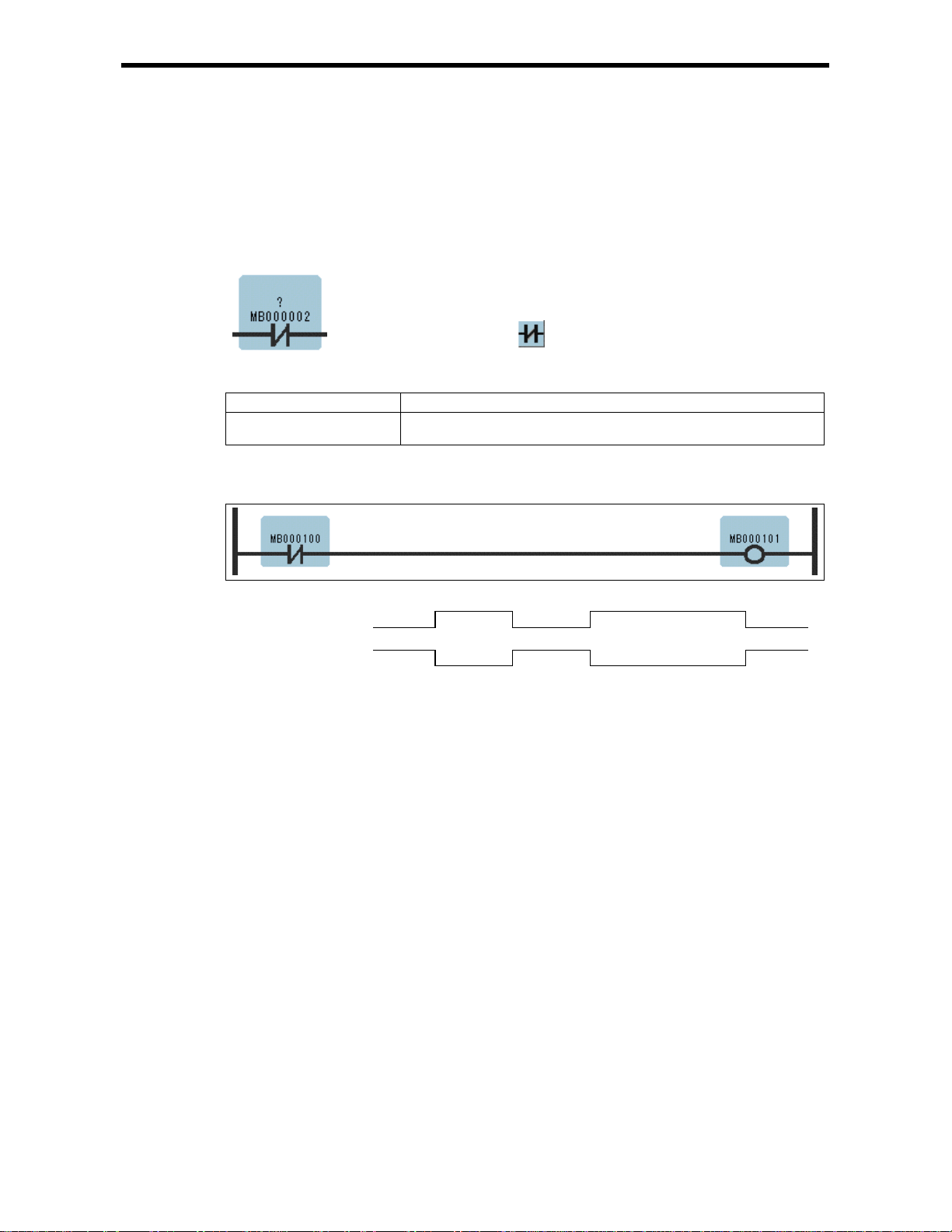
1.2 N.C. Contact instruction (NCC)
[Outline]
The NCC se ts t he value of th e bit ou tpu t to OFF w hen t he val ue of th e refe renc ed re giste r is 1 (O N),
and to ON when the value of the referenced register is 0 (OFF).
[Format]
[Parameter]
Parameter Name Setting
Relay No. · Any bit type register
· Any bit type register with subscript
[Program Example]
When MB000100 becomes ON, MB000101 becomes OFF.
Symbol : NCC
Full Name : NC Contact
Category : RELAY
Icon :
1.2 N.C. Con t act instructio n (NCC)
MB000100ONOFF
MB000101ONOFF
1-3
Page 9

1.3 10-MS ON-DELAY TIMER Inst ructions (TO N[10ms])
1.3 10-MS ON-DELAY TIMER Instruction (TON[10ms])
[Outline]
The TON[10ms] is executed while the immediately-preceding value of the bit input is ON. The value
of the bit output is set to ON when the timer value reaches the set value. The timer stops when the
immediately-preceding value of the bit input is set to OFF during timing. When the bit input is set to
ON again, timing restarts from the beginning (0). A value equal to the actual timed time (10ms Unit)
is stored in the timer value register.
[Format]
Symbol : TON[10ms]
Full Name : On-Del ay Timer[10ms]
Category : RELAY
Icon :
[Parameter]
Parameter Name Setting
Set (set value) · Any integer type register
· Any integer type register with subscript (0 to 65535 : in 0.01sec unit)
· Constant
Count (timer value) · Any integer type register (except for # and C registers)
· Any integer type register with subscript (except for # and C registers)
[Program Example]
ON
MB000100
MB000101
OFF
ON
OFF
500
MB000011
0 5.00s-Ts
(Ts = Scan set value)
Notes: MW00011 works as timer count register. Thus, it is essen tial tha t th ere is no over la p. Set
an unused register.
1-4
Page 10
1.4 10-MS O FF-DELAY TIMER Instr uctions (TOFF[10ms])
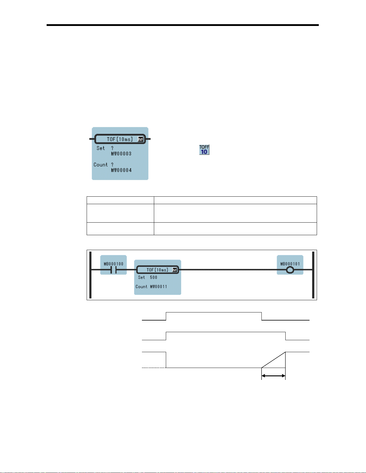
1.4 10-MS OFF-DELAY TIMER Instruction (TOFF[10ms])
[Outline]
The TOFF[10ms] is executed while the immediately-preceding value of the bit input is OFF. The
value of the bit output is set to OFF when the timer value reaches the set value.
The timer stops when the immediately-preceding value of the bit input is set to ON during timing.
When the bit input is set to OFF again, timing restarts from the beginning (0). A value equal to the
actual timed time (10ms Unit) is stored in the timer value register.
[Format]
Symbol : TOFF[10ms]
Full Name : Off-Dela y Timer[10ms]
Category : RELAY
Icon :
[Parameter]
Parameter Name Setting
Set (set value) · Any integer type register
· Any integer type register with subscript (0 to 65535 : 0.01sec unit)
· Constant
Count (timer value) · Any integer type register (except for # and C registers)
· Any integer type register with subscript (except for # and C registers)
[Program Example]
ON
MB000100
MB000101
OFF
ON
OFF
500
MB000011
0
500s-Ts
(Ts = Scan set value)
Notes: MW00011 works as timer count register. Thus, it is essen tial tha t th ere is no over la p. Set
an unused register.
1-5
Page 11
1.5 1-S ON-DELAY TIMER Inst ru ction s (TO N[1s] )
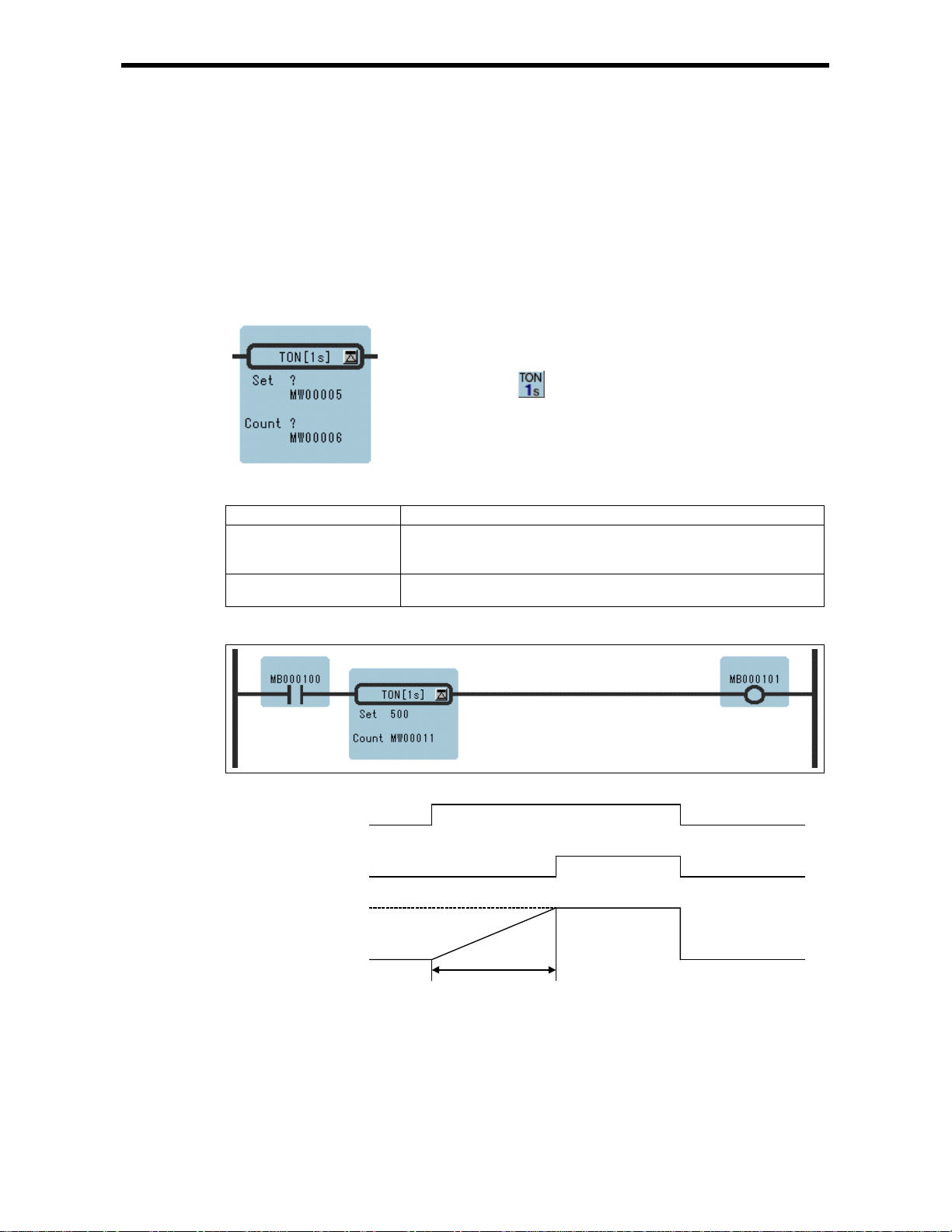
1.5 1-S ON-DELAY TIMER Instruction (TON[1s])
[Outline]
The TON[1s] times while the immediately-preceding value of the bit input is ON. The value of the bit
output is set to ON when the timer value reaches the set value. The timer stops when the immediatelypreceding value of the bit input is set to ON during timing. When the bit input is set to OFF again,
timing restarts from the beginning (0). A value equal to the actual timed time (1s Unit) is stored in the
timer value regis ter.
[Format]
Symbol : TON[1s]
Full Name : On-Delay Timer[1s]
Category : RELAY
Icon :
[Parameter]
Parameter Name Setting
Set (set value) · Any integer type register
· Any integer type register with subscript (0 to 65535 : 1sec unit)
· Constant
Count (timer value) · Any integer type register (except for # and C registers)
· Any integer type register with subscript (except for # and C registers)
[Program Example]
ON
MB000100
MB000101
OFF
ON
OFF
500
MB000011
0 500s-Ts
(Ts = Scan set value)
Notes: MW00011 works as timer count register. Thus, it is essen tial tha t th ere is no over la p. Set
an unused register.
1-6
Page 12
1.6 1-S OFF-DELAY TIMER Instruc t ion s (TOFF[1s])
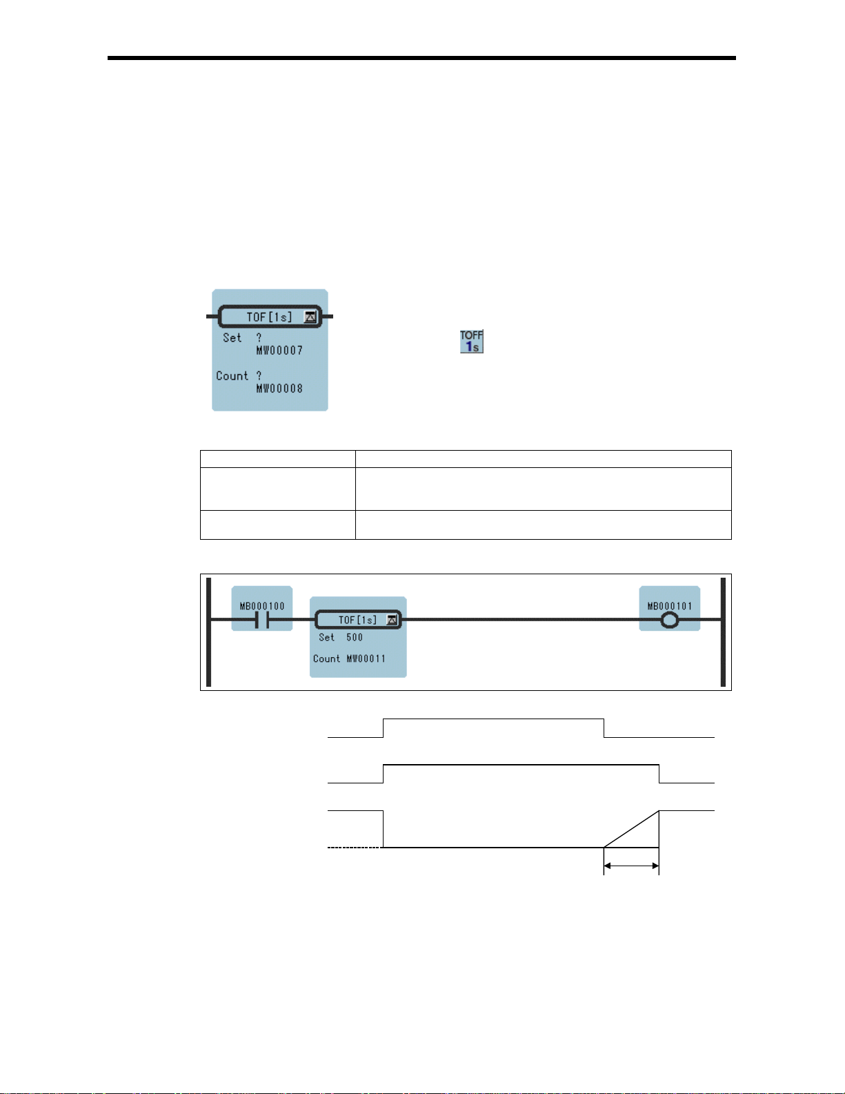
1.6 1-S OFF-DELAY TIMER Instruction (TOFF[1s])
[Outline]
The TOFF[1s] times while the immediately-preceding value of the bit input is OFF. The value of the
bit output is set to OFF when the timer value reaches the set value. The timer stops when the
immediately-preceding value of the bit input is set to ON during timing. When the bit input is set to
OFF again, timing restarts from the beginning (0). A value equal to the actual timed time (1s Unit) is
stored in the timer value register.
[Format]
Symbol : TOFF[1s]
Full Name : Off-Dela y Timer[1s]
Category : RELAY
Icon :
[Parameter]
Parameter Name Setting
Set (set value) · Any integer type register
· Any integer type register with subscript (0 to 65535 : 1sec unit)
· Constant
Count (timer value) · Any integer type register (except for # and C registers)
· Any integer type register with subscript (except for # and C registers)
[Program Example]
ON
MB000100
MB000101
OFF
ON
OFF
500
MB000011
0
500s-Ts
(Ts = Scan set value)
Notes: MW00011 works as timer count register. Thus, it is essen tial tha t th ere is no over la p. Set
an unused register.
1-7
Page 13
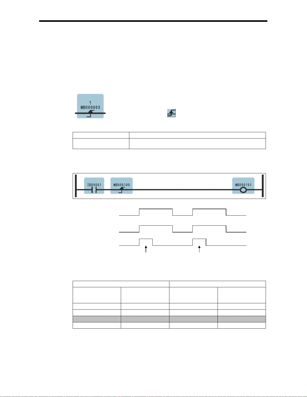
1.7 RISING PULSE Instruction (ON – PLS)
[Outline]
The ON-PLS sets the value of the bit input to ON during one scan when the immediately-preceding
value of the b it out p ut c han ges fro m OFF to ON . The de si gnate d r egis te r is us e d to st or e the pre vi ous
value of the bit output.
[Format]
Symbol : ON-PLS
Full Na m e : Rise Pulse
Category : RELAY
Icon :
[Parameter]
Parameter Name Setting
Register No.
[Program Example]
When IB00001 turns ON from OFF, MB000101 turns ON and stays ON during 1 scan. MB000100 is
used to store the previous value of IB00001.
· Any bit type register (except for # and C regi ster)
· Any bit type register with subscript (except for # and C registers)
1.7 RISING PULSE Instruct ions ( ON – PLS)
ON
IB00001
MB000100
MB000101
OFF
ON
OFF
ON
OFF
1 scan 1 scan
Register status of Rising pulse instruction is shown in Table 1.1.
Table 1.1 Register Status with Rising Pulse Instruction
Input Result
IB00001 MB000100
(Previous value of
IB00001)
OFF OFF OFF OFF
OFF ON OFF OFF
ON OFF ON ON
ON ON ON OFF
MB000100
(IB00001 stored)
MB000101
Notes: Case of Program Example, the instruction is used not for rise detection of MB00010 0 but
is used for rise detecti on of IB00001. MB000100 is used only for storing the pr evious
value of IB00001.
1-8
Page 14
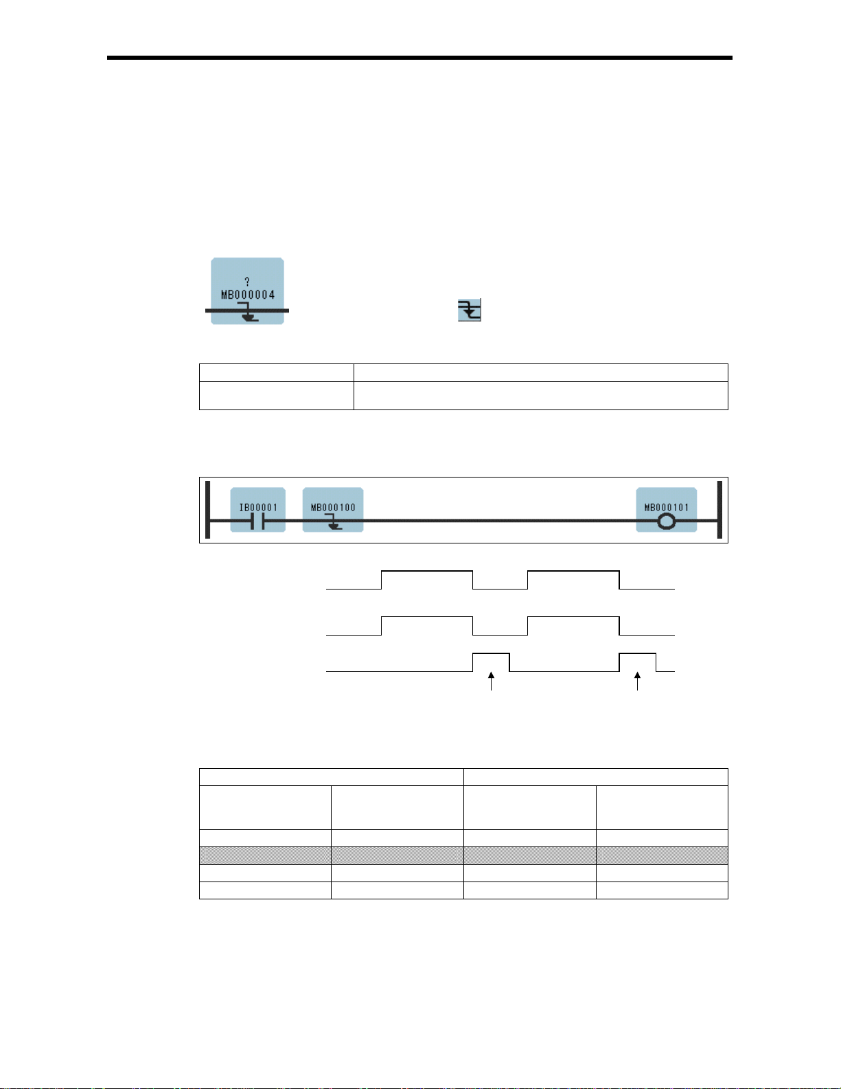
1.8 FALLING PULSE Instruction (OFF – PLS)
[Outline]
The OFF-PLS sets the value of the bit input to ON for one scan when the immediately-preceding value
of the bi t ou tp ut c ha nges fr om ON to OF F. The de si gn ate d reg ist er is us ed to st or e the pr evi ou s val ue
of the bit output.
[Format]
Symbol : OFF-PLS
Full Name : Fall Pulse
Category : RELAY
Icon :
[Parameter]
Parameter Name Setting
Register No.
· Any bit type register (except for # and C regi ster)
· Any bit type register with subscript (except for # and C registers)
[Program Example]
When IB00001 turns OFF, MB000101 turns ON an d stays ON during 1 scan. MB000100 is used t o
store the previous value of IB00001.
1.8 FALLING PULSE I nstructions (OFF – PLS)
ON
IB00001
MB000100
MB000101
OFF
ON
OFF
ON
OFF
1 scan1 scan
Register status of Falling pulse instruction is shown in Table 1.2.
Table 1.2 Register Status with Fa llin g Pulse In s t ruction
Input Result
MB000100
IB00001
OFF OFF OFF OFF
OFF ON OFF ON
ON OFF ON OFF
ON ON ON OFF
(Previous value of
IB00001)
MB000100
(IB00001 stored)
MB000101
Notes: Case of Program Example, the instruction is us ed not for fa ll detecti on of MB000100 but
is used for fall detection of IB00001. MB000100 is used only for storing the previous
value of IB00001.
1-9
Page 15
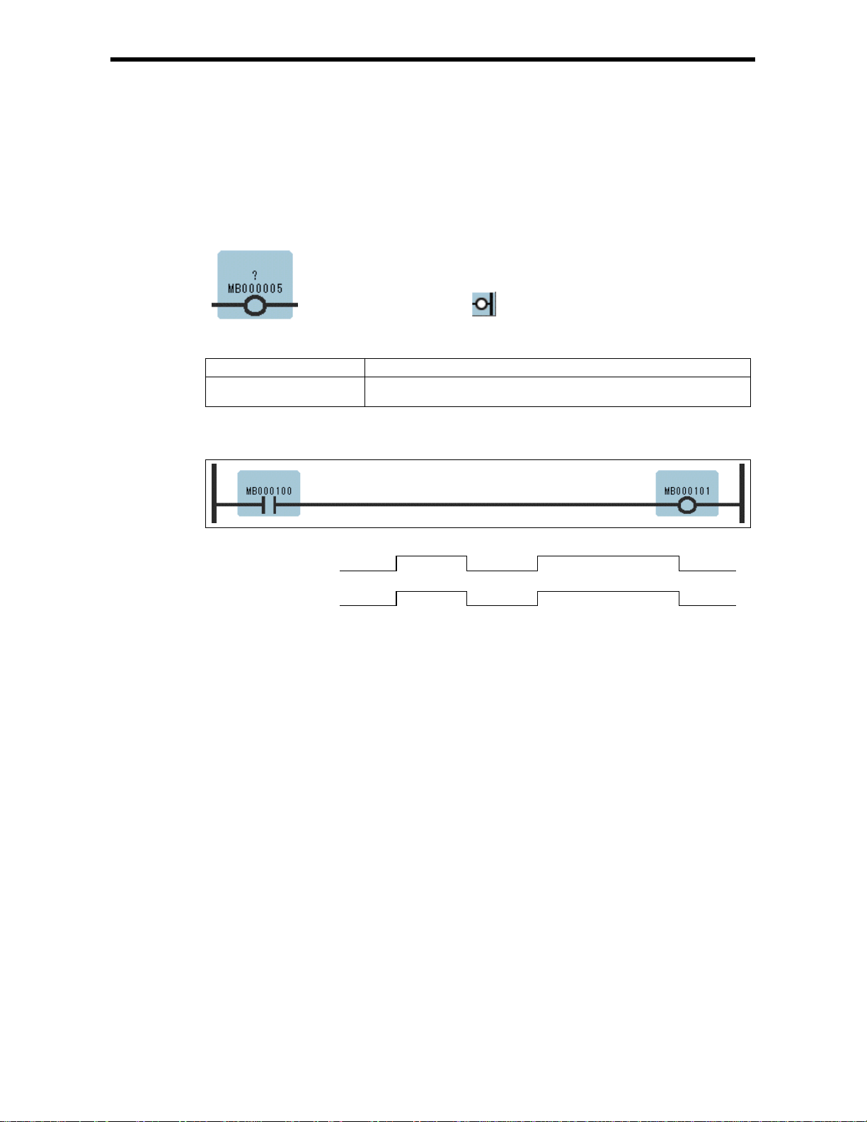
1.9 COIL Instruction (COIL)
[Outline]
The COIL sets the value of the referenced register to 1 (ON) when the immediately-preceding value of
the bit input is ON, and to 0 (OFF) when the immediately-preceding value of the bit input is OFF.
[Format]
[Parameter]
Parameter Name Setting
Coil No. · Any bit type register (e xcept for # and C register )
[Program Example]
When MB000100 becomes ON, MB000101 becomes ON.
1.9 COIL Inst ruction (COIL)
Symbol : COIL
Full Na m e : Coil
Category : RELAY
Icon :
· Any bit type register with subscript (except for # and C registers)
MB000100ONOFF
MB000101ONOFF
1-10
Page 16
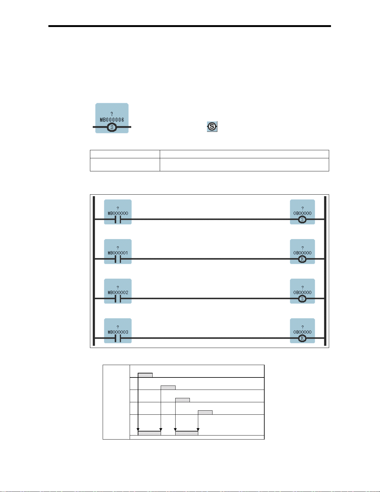
1.10 SET COIL Instruction (S-COIL)
[Outline]
The S-COIL turns ON the output when the execution condition is satisfied, and maintains the ON state.
[Format]
[Parameter]
Parameter Name Setting
Coil No. · Any bit type register (e xcept for # and C register )
· Any bit type register with subscript (except for # and C registers)
[Program Example]
Case where the same output destination is designated multiple times.
Symbol : S-Coil
Full Name : Set Coil
Category : RELAY
Icon :
1.10 SET COIL Instructions (S-COIL)
The above example acts as in the g r aph below.
MB000000
MB000001
MB000002
MB000003
*
OB00000
* When OB00000 is OFF,
with the "set coil"
instruction, OB00000
turns ON.
1-11
Page 17

1.11 RESET COIL Instruction (R-COIL)
[Outline]
The R-COIL turns OFF the output when the execution condition is sati sfied, and maintains the OFF
state.
[Format]
Symbol : R-Coil
Full Name : Reset Coil
Category : RELAY
Icon :
[Parameter]
Parameter Name Setting
Coil No. · Any bit type register (e xcept for # and C register )
· Any bit type register with subscript (except for # and C registers)
[Program Example]
Case where the same output destination is designated multiple times.
1.11 RESET COIL In st ructions (R-CO IL)
The above example acts as in the g r aph below.
MB000000
MB000001
MB000002
MB000003
*
OB00000
* When OB00000 is ON,
with the "reset coil"
instruction, OB00000
turns OFF.
1-12
Page 18

2 Numeric Operation Instructions
2 Numeric Operation Instructions
2.1 STORE Instruction (STOR E)
2.2 ADDITION Instruction (ADD)
2.3 EXTENDED ADDITION Instruction (ADDX)
2.4 SUBTRACTION Instruction (SUB)
2.5 EXTENDED SUBTRACTION Instruction (SUBX)
2.6 MULTIPLICATION Instruction (MUL)
2.7 DIVISION Instruction (DIV)
2.8 MOD Instruction (MOD)
2.9 REM Instruction (REM)
2.10 INC Instruction (INC)
2.11 DEC Instruction (DEC)
2.12 ADD TIME Instruction (TMADD)
2.13 SUBTRACT TIME In struction (TMSUB)
2.14 SPEND TIME Instruction (SPEND)
2.15 SIGN INVERSION Instruction (INV)
2.16 1’S COMPLEMENT Instruction (COM)
2.17 ABSO LUTE VALUE CONVERSION Instruction (ABS)
2.18 BINARY CONVERSION Instruction (BIN)
2.19 BCD CONV ERSION Instruction (BCD)
2.20 PARITY CONVE RSION Inst r uc ti on (PARITY)
2.21 ASCII C ONVERSION Instruction (ASC II)
2.22 ASCII CONVERSION 2 Instruction (BINASC)
2.23 ASCII CONVERSION 3 Instruction (ASCBIN)
・・・・・・・・・・・・・・・・・・・・・・・・・・・・・・・・・・・・・・・・・・・
・・・・・・・・・・・・・・・・・・・・・・・・・・・・・・・・・・・・・・・・・・・
・・・・・・・・・・・・・・・・・・・・・・・・・・・・・・
・・・・・・・・・・・・・・・・・・・・・・・・・・・・・・・・・・・・・・
・・・・・・・・・・・・・・・・・・・・・・・・・
・・・・・・・・・・・・・・・・・・・・・・・・・・・・・・・・・・・
・・・・・・・・・・・・・・・・・・・・・・・・・・・・・・・・・・・・・・・・・・・・
・・・・・・・・・・・・・・・・・・・・・・・・・・・・・・・・・・・・・・・・・・・・・・・
・・・・・・・・・・・・・・・・・・・・・・・・・・・・・・・・・・・・・・・・・・・・・・・
・・・・・・・・・・・・・・・・・・・・・・・・・・・・・・・・・・・・・・・・・・・・・・・・
・・・・・・・・・・・・・・・・・・・・・・・・・・・・・・・・・・・・・・・・・・・・・・
・・・・・・・・・・・・・・・・・・・・・・・・・・・・・・・・・・・・・・
・・・・・・・・・・・・・・・・・・・・・・・・・・・・・・・・
・・・・・・・・・・・・・・・・・・・・・・・・・・・・・・・・・・・・
・・・・・・・・・・・・・・・・・・・・・・・・・・・・・・・・・・・
・・・・・・・・・・・・・・・・・・・・・・・・・・・・・・・・
・・・・・・・・・・・・・・・・・・・
・・・・・・・・・・・・・・・・・・・・・・・・・・・・・・
・・・・・・・・・・・・・・・・・・・・・・・・・・・・・・・・
・・・・・・・・・・・・・・・・・・・・・・・・・・
・・・・・・・・・・・・・・・・・・・・・・・・・・・・・・
・・・・・・・・・・・・・・・・・・・・・・・・・・
・・・・・・・・・・・・・・・・・・・・・・・・・・
2-2
2-4
2-6
2-7
2-9
2-10
2-12
2-14
2-15
2-16
2-18
2-20
2-22
2-24
2-26
2-28
2-29
2-31
2-32
2-33
2-34
2-35
2-36
2-1
Page 19
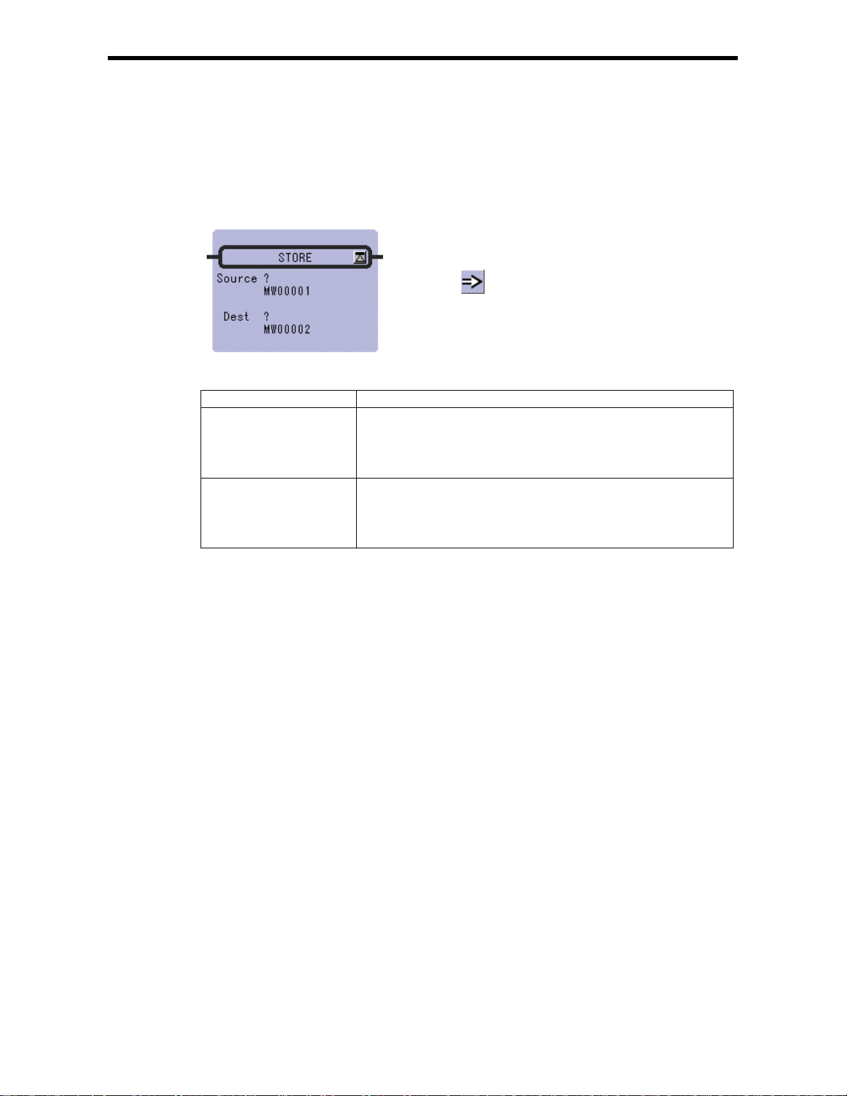
2.1 STORE Instruction (STORE)
[Outline]
The STORE instruction stores the contents of Source in the Dest.
[Format]
Symbol : STORE
Full Name : St ore
Category : MATH
Icon :
2.1 STORE Instru ct ion (STORE)
[Parameter]
Parameter Name Setting
Source · Any integer type, double-length integer type and real number type register
· Any integer type, double-length integer t ype and real number type register
with subscript
· Subscript register
· Constant
Dest · Any integer type, double-length integer t ype and rea l number type regist er
(except for # and C registers)
· Any integer type, double-length integer t ype and real number type register
with subscript (except for # and C registers)
· Subscript register
2-2
Page 20
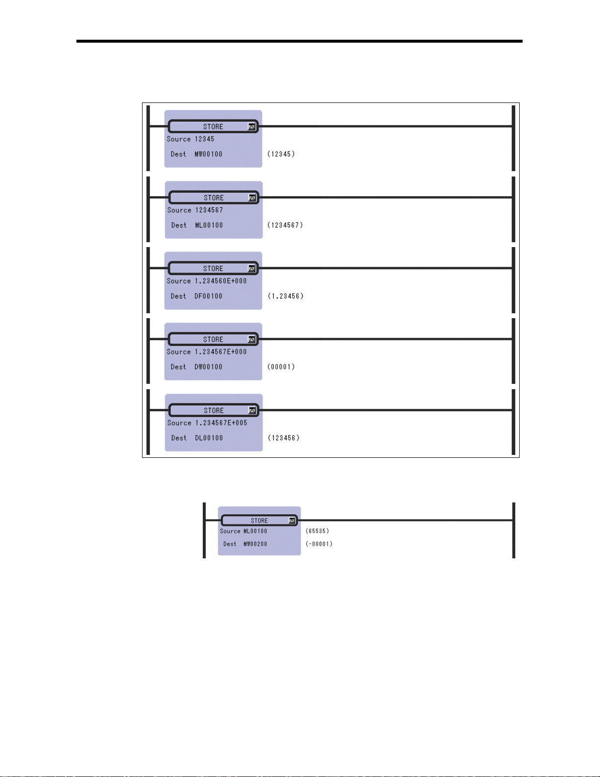
2.1 STORE Instru ct ion (STORE)
[Program Example]
Notes: When a double-length i nteger type data is s tored in an in teger type regis ter, the lower 16
bits are stored as they are. Be careful s ince an operation error w ill not occur even if the
data to be stored exceeds the integer range (-32768 to 32767).
2-3
Page 21
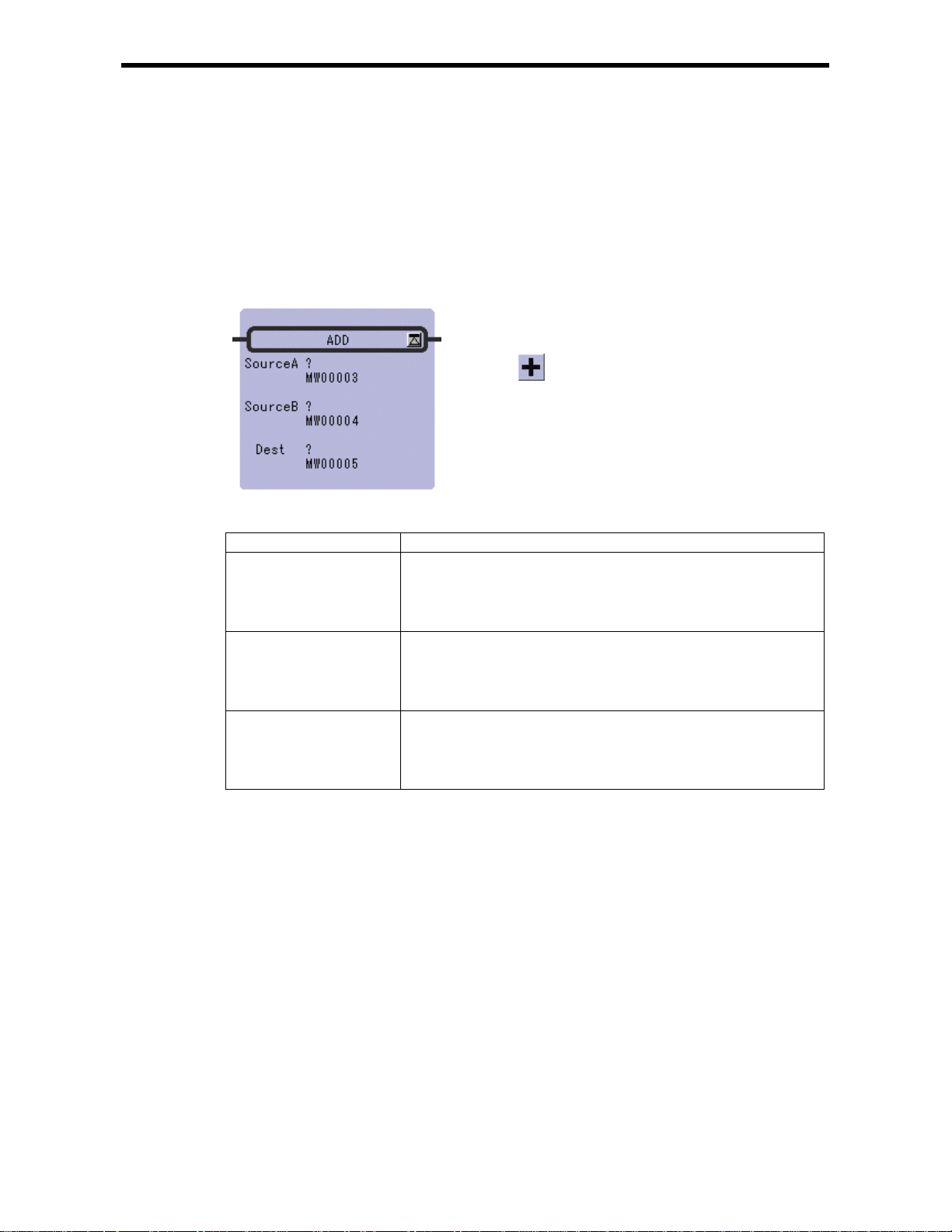
2.2 ADDITION Instruction (ADD)
[Outline]
The ADD instruction adds integer, double-length integer, and real number values. Source B is added
to So urce A and stored in the Dest. If the res ult of ad ding inte ger valu es is great er than 32767, a n
overflow error occurs. If the result of adding double-length integer values is greater than 2147483647,
an overflow erro r o ccurs.
[Format]
Symbol : ADD
Full Name : Add
Category : MATH
Icon :
2.2 ADDITION In st ruction (ADD)
[Parameter]
Parameter Name Setting
Source A · Any integer type, double-length integer type and real number type register
· Any integer type, d ouble-lengt h integer t ype and real number t ype register
with subscript
· Subscript register
· Constant
Source B · Any integer type, double-length integer type and real number type register
· Any integer type, d ouble-lengt h integer t ype and real number t ype register
with subscript
· Subscript register
· Constant
Dest · Any integer t ype, double-len gth integer t ype and real number type register
(except for # and C registers)
· Any integer type, d ouble-lengt h integer t ype and real number t ype register
with subscript (except for # and C registers)
· Subscript register
2-4
Page 22
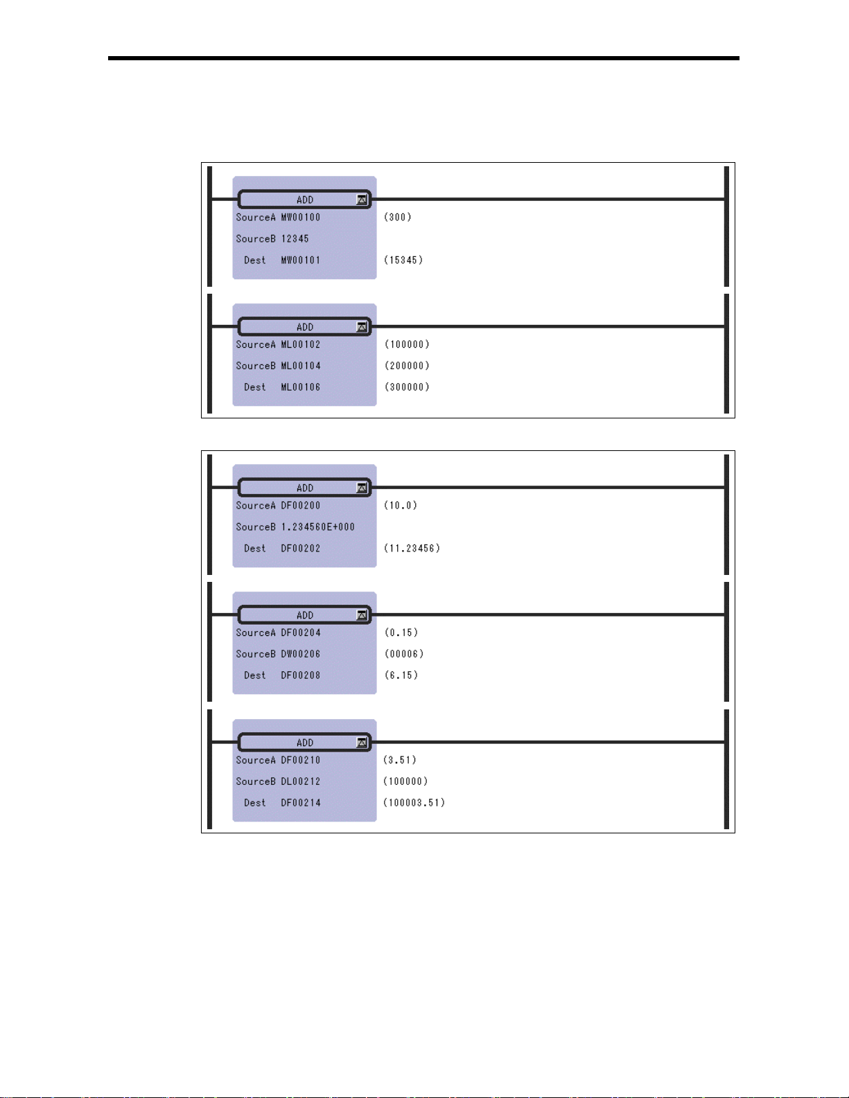
2.2 ADDITION In st ruction (ADD)
[Program Example ]
Addition of integer type values
Addition of real nu mber type values
Notes: In the case of double-length integer type values, an operation using addition and
subtraction instructions (+, –, ++, --) will be a 32-bit operation. However, when an
addition or subtraction instruction is used in a remainder correction operation (where a
multiplication instruction (×) is the immediately preceding instruction and a division
instruction (÷) is the immediately subsequent instruction), the operation will be a 64-bit
operation.
2-5
Page 23
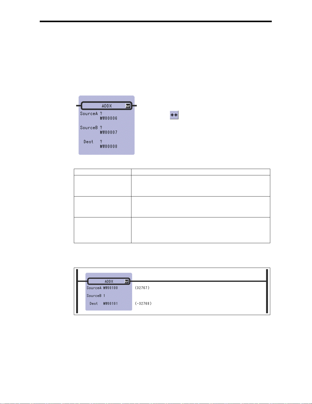
2.3 EXTENDED ADDITI ON Instruction (ADDX)
2.3 EXTENDED ADDITION Instruction (ADDX)
[Outline]
The ADDX instruction adds integer values. Source B is add ed to Source A and stored in the Dest. No
operation error occurs, even if the operation results in an overflow. Otherwise, the ADDX is much the
same as the ADD.
[Format]
Symbol : ADDX
Full Name : Expanded Add
Category : MATH
Icon :
[Parameter]
Parameter Name Setting
Source A · Any integer type and double-length integer type register
· Any integer type and double-length integer type register with subscript
· Subscript register
· Constant
Source B · Any integer type and double-length integer type register
· Any integer type and double-length integer type register with subscript
· Subscript register
· Constant
Dest · Any integer type an d double-lengt h integer type regi ster (except f or # and
C registers)
· Any integer type and double-length integer type register with subscript
(except for # and C registers)
· Subscript register
[Program Example]
This instruction is used in cases where it is desirable that operation errors do not occur in the addition
of integer type values.
Notes: In the case of double-length integer type values, an operation using addition and
subtraction instructions (+, –, ++, --) will be a 32-bit operation. However, when an
addition or subtraction instruction is used in a remainder correction operation (where a
multiplication instruction (×) is the immediately preceding instruction and a division
instruction (÷) is the immediately subsequent instruction), the operation will be a 64-bit
operation.
2-6
Page 24

2.4 SUBTRACTION Instruction ( SUB)
[Outline]
The SUB instruction subtracts integer, double-length integer, and real number values. Source B is
subtracted to Source A and stored in the Dest. If the result of subtr ac ting intege r va lu e s is sma l le r th a n
– 32768, an underflow error occurs. If the result of subtracting double-length integer values is smaller
than – 214748 3648, an under flow error occurs.
[Format]
Symbol : SUB
Full Name : Subtract
Category : MATH
Icon :
2.4 SUBTRACTION I n st ruction (SUB)
[Parameter]
Parameter Name Setting
Source A · Any integer type, double-length integer type and real number type register
· Any integer type, d ouble-lengt h integer t ype and real number t ype register
with subscript
· Subscript register
· Constant
Source B · Any integer type, double-length integer type and real number type register
· Any integer type, d ouble-lengt h integer t ype and real number t ype register
with subscript
· Subscript register
· Constant
Dest · Any integer t ype, double-len gth integer t ype and real number type register
(except for # and C registers)
· Any integer type, d ouble-lengt h integer t ype and real number t ype register
with subscript (except for # and C registers)
· Subscript register
2-7
Page 25
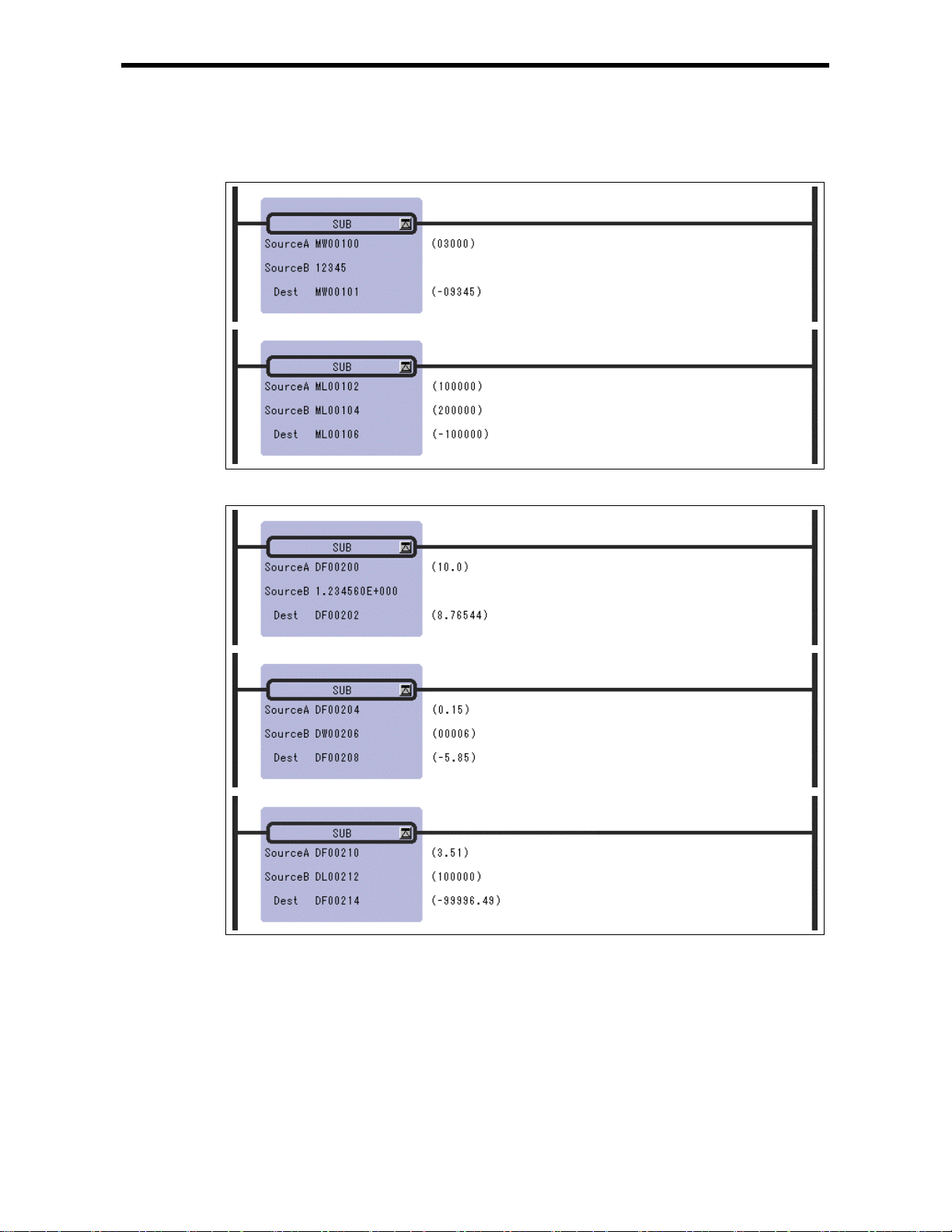
2.4 SUBTRACTION I n st ruction (SUB)
[Program Example]
Subtraction of integer type valu es
Subtraction of re al number t ype values
Notes: In the case of double-length integer type values, an operation using addition and
subtraction instructions (+, –, ++, --) will be a 32-bit operation. However, when an
addition or subtraction instruction is used in a remainder correction operation (where a
multiplication instruction (×) is the immediately preceding instruction and a division
instruction (÷) is the immediately subsequent instruction), the operation will be a 64-bit
operation.
2-8
Page 26
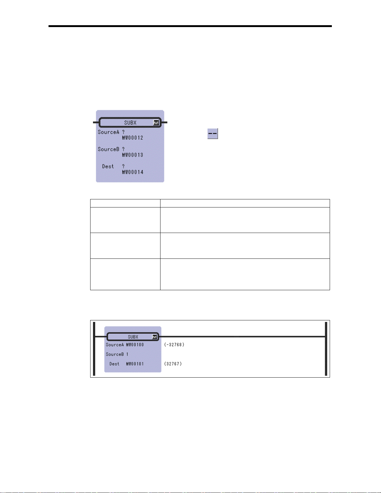
2.5 EXTENDED SUBTRACTION Instruct ion (SUBX)
2.5 EXTENDED SUBTRACTION Instruction (SUBX)
[Outline]
The SUBX instruction subtracts integer values. No operation error occurs, even if the operation
results in an underflow.
[Format]
Symbol : SUBX
Full Name : Expanded Subtract
Category : MATH
Icon :
[Parameter]
Parameter Name Setting
Source A · Any integer type and double-length integer type register
· Any integer type and double-length integer type register with subscript
· Subscript register
· Constant
Source B · Any integer type and double-length integer type register
· Any integer type and double-length integer type register with subscript
· Subscript register
· Constant
Dest · Any integer type an d double-lengt h integer type regi ster (except f or # and
C registers)
· Any integer type and double-length integer type register with subscript
(except for # and C registers)
· Subscript register
[Program Example]
This instruction is used in cases where it is desirable that operation errors do not occur in the
subtrac tion of integer type valu es .
Notes: In the case of double-length integer type values, an operation using addition and
subtraction instructions (+, –, ++, --) will be a 32-bit operation. However, when an
addition or subtraction instruction is used in a remainder correction operation (where a
multiplication instruction (×) is the immediately preceding instruction and a division
instruction (÷) is the immediately subsequent instruction), the operation will be a 64-bit
operation.
2-9
Page 27
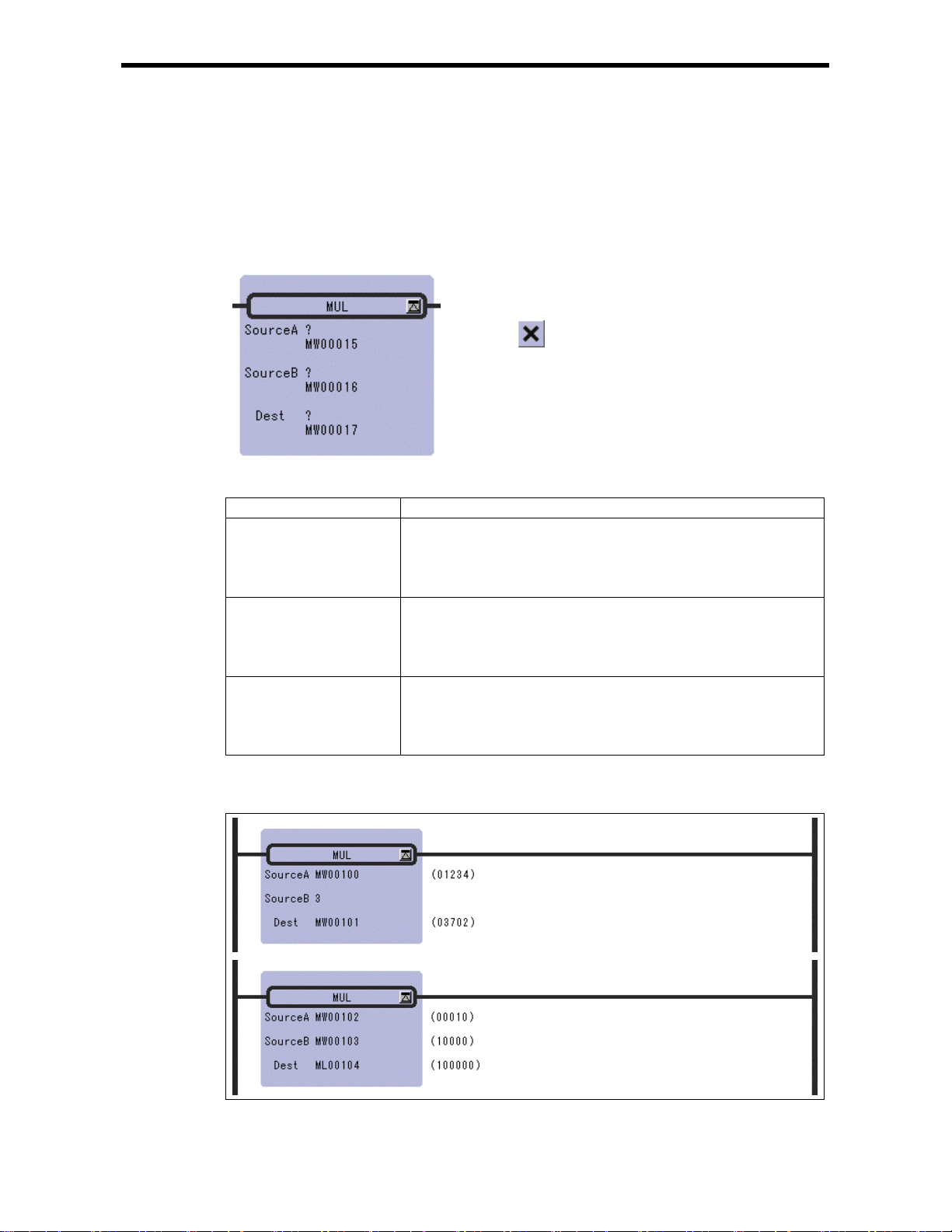
2.6 MULTIPLICATION Instruction (MUL)
[Outline]
The MUL instruction multiplies integer, double-length integer, and real number values. Source B is
multiplied to Source A and stored in the Dest.
[Format]
Symbol : MUL
Full Name : Multiply
Category : MATH
Icon :
2.6 MULTIPLICATIO N I n st ruction (MUL)
[Parameter]
Parameter Name Setting
Source A · Any integer type, double-length integer type and real number type register
· Any integer type, d ouble-lengt h integer t ype and real number t ype register
with subscript
· Subscript register
· Constant
Source B · Any integer type, double-length integer type and real number type register
· Any integer type, d ouble-lengt h integer t ype and real number t ype register
with subscript
· Subscript register
· Constant
Dest · Any integer t ype, double-len gth integer t ype and real number type register
(except for # and C registers)
· Any integer type, d ouble-lengt h integer t ype and real number t ype register
with subscript (except for # and C registers)
· Subscript register
[Program Example]
Multiplication of in t eger type valu es
2-10
Page 28
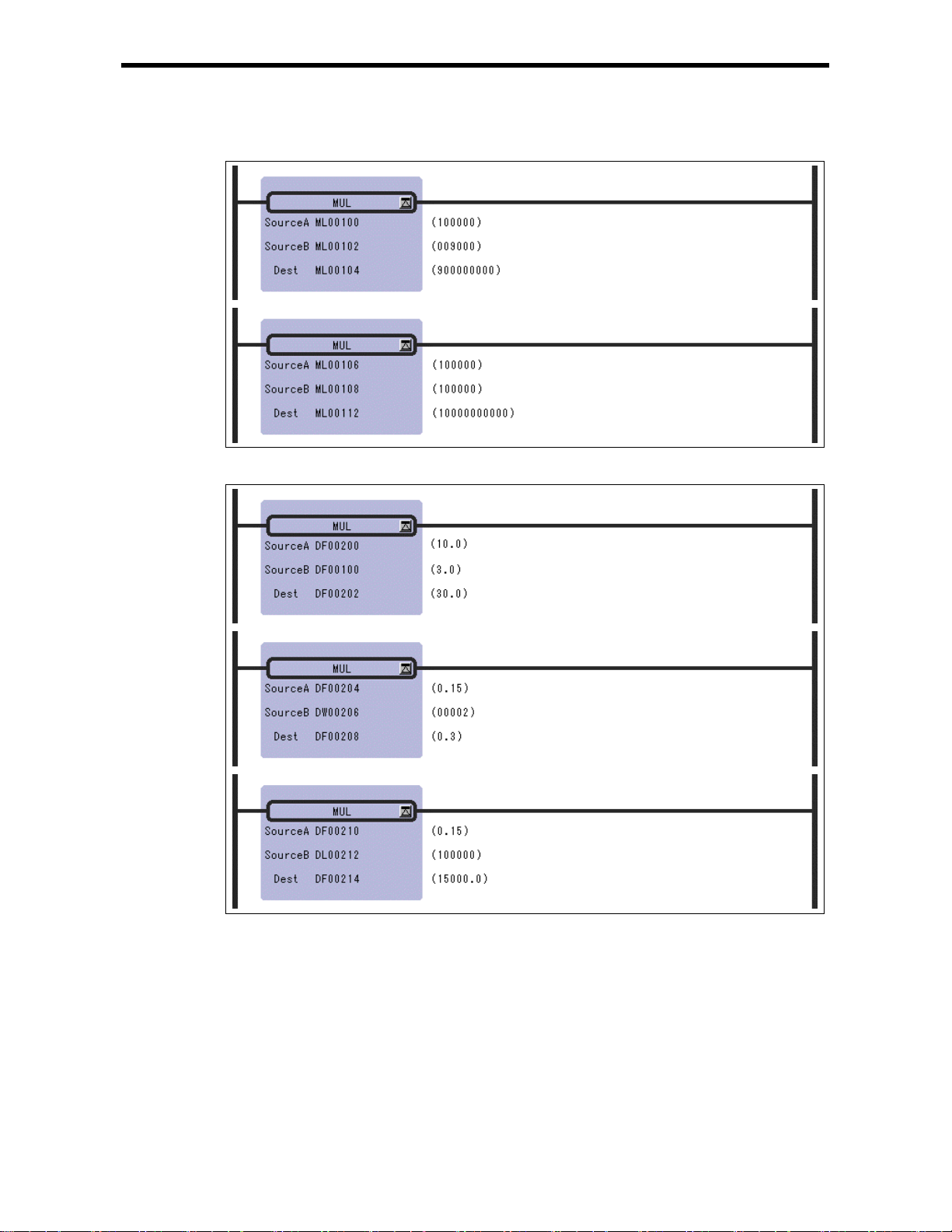
2.6 MULTIPLICATIO N I n st ruction (MUL)
Multiplication of double-length integer type values
Multiplication of real number type values
Notes: In the case of double-length integer type values, an operation using addition and
subtraction instructions (+, –, ++, --) will be a 32-bit operation. However, when an
addition or subtraction instruction is used in a remainder correction operation (where a
multiplication instruction (×) is the immediately preceding instruction and a division
instruction (÷) is the immediately subsequent instruction), the operation will be a 64-bit
operation.
2-11
Page 29
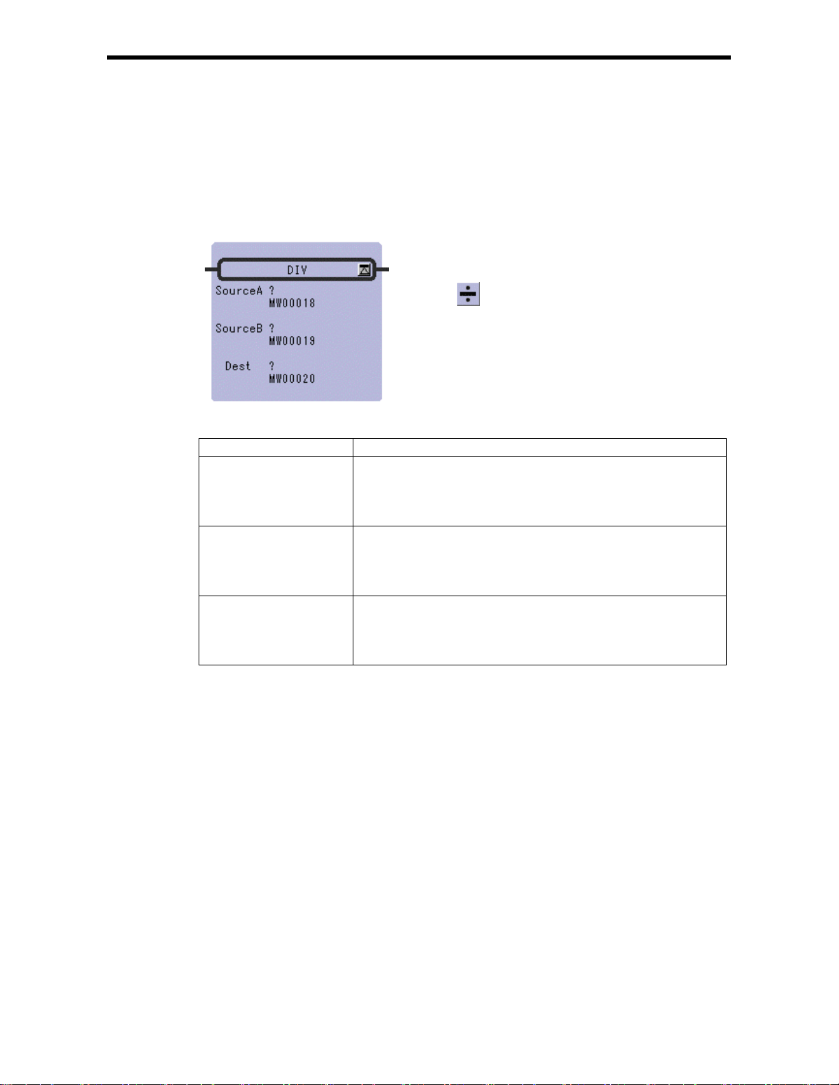
2.7 DIVISION Instruction (DIV)
[Outline]
The DIV instruction divides integer, double-length integer, and real number values. Source A is
divided by Source B and stored in the Dest.
[Format]
Symbol : DIV
Full Name : Divide
Category : MATH
Icon :
2.7 DIVISION Instruction (DIV)
[Parameter]
Parameter Name Setting
Source A · Any integer type, double-length integer type and real number type register
· Any integer type, d ouble-lengt h integer t ype and real number t ype register
with subscript
· Subscript register
· Constant
Source B · Any integer type, double-length integer type and real number type register
· Any integer type, d ouble-lengt h integer t ype and real number t ype register
with subscript
· Subscript register
· Constant
Dest · Any integer t ype, double-len gth integer t ype and real number type register
(except for # and C registers)
· Any integer type, d ouble-lengt h integer t ype and real number t ype register
with subscript (except for # and C registers)
· Subscript register
2-12
Page 30
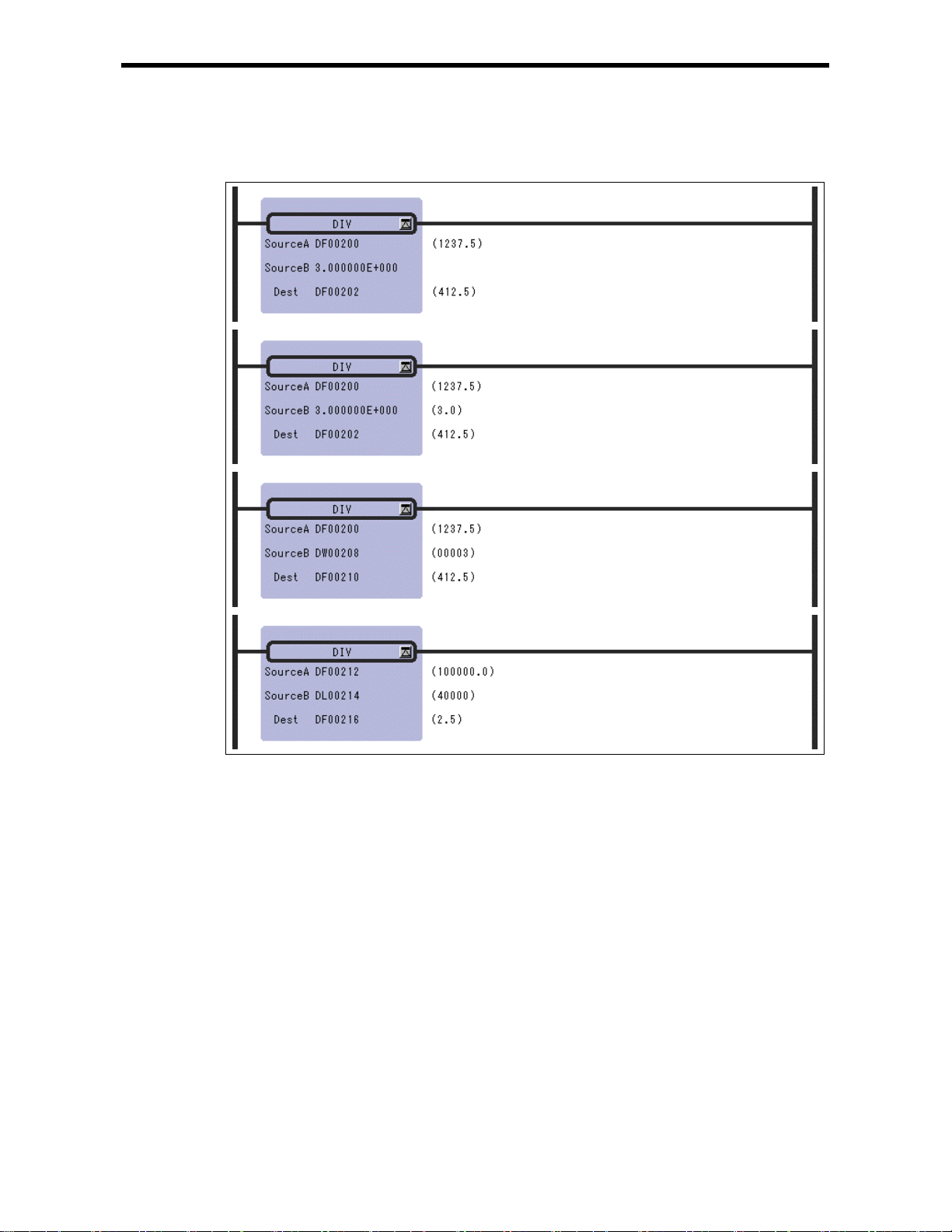
2.7 DIVISION Instruction (DIV)
[Program Example]
Real number type data
2-13
Page 31

2.8 MOD Instruction (MOD)
[Outline]
The MOD instruction outputs the remainder of integer or double-length integer division to the Dest.
Always execute the MOD immediately after the division instruction. If the MOD is executed
somewhere else, the operation results obtained before the next entry instruction cannot be guaranteed.
[Format]
Symbol : MOD
Full Name : Integer Remainder
Category : MATH
Icon :
2.8 MOD Instr uctio n (MOD)
[Parameter]
Parameter Name Setting
Dest · Any integer type and double-length integer type register (except for # and
C registers)
· Any integer type and double-length integer type register with subscript
(except for # and C registers)
· Subscript register
[Program Example]
The quotient of an integer type division is stoned in MW00101 and the remainder is stored in
MW00102.
2-14
Page 32
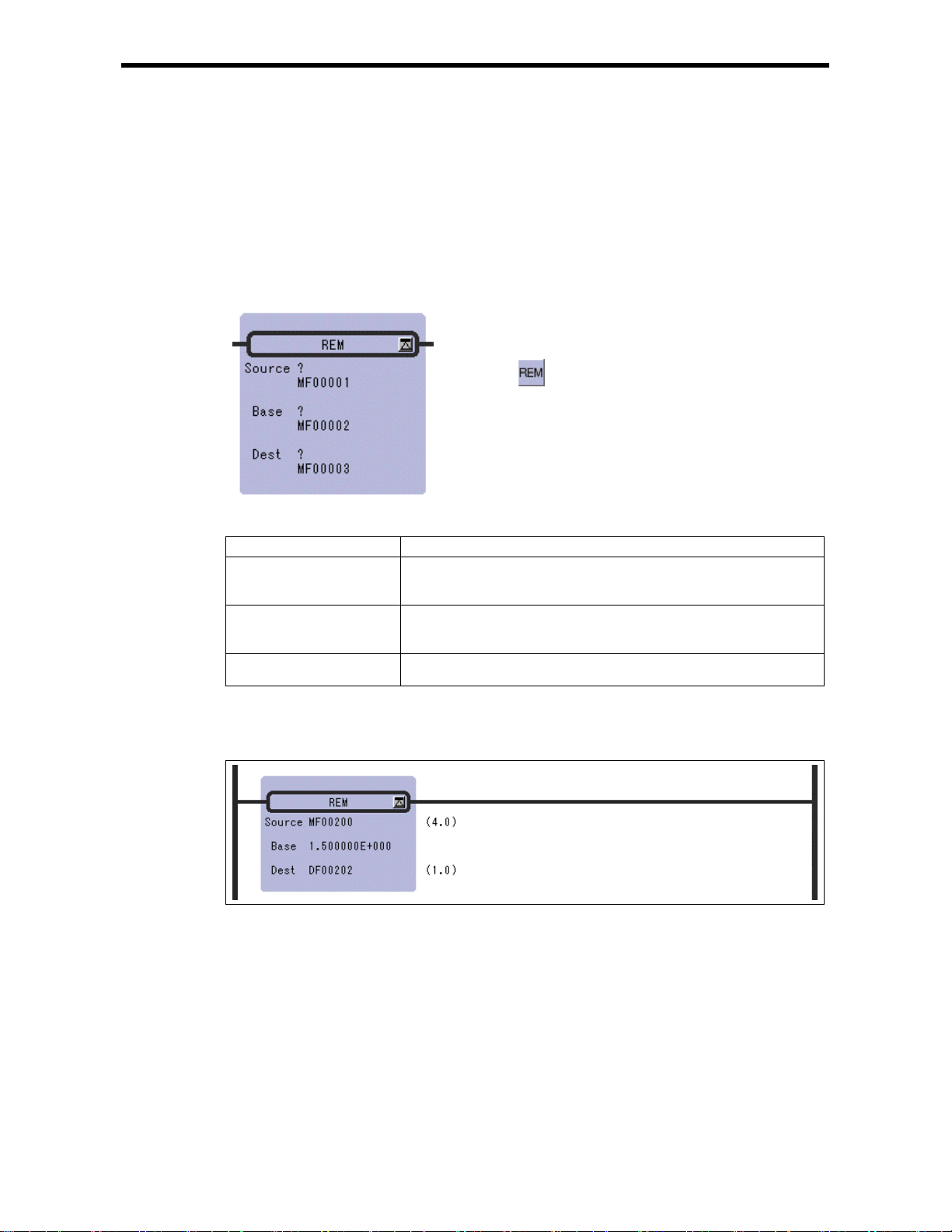
2.9 REM Instruction (REM)
[Outline]
The REM i nstr uctio n out puts t he rema inde r of re al num ber di visi on t o the Dest. Here, the remainder
refers to the remainder obtained by repeatedly subtracting the Base designated by the Source. Thus,
the n is the number of times subtraction is repeated.
Dest = Source – (Base × n) (0 ≦ Dest < Base)
[Format]
Symbol : REM
Full Name : Real Re mainder
Category : MATH
Icon :
2.9 REM Instruc t ion (R EM )
[Parameter]
Parameter Name Setting
Source · Any real number type register
· Any real number type register with subscript
· Constant
Base · Any real number type register
· Any real number type register with subscript
· Constant
Dest · Any real number type register (except for # and C register)
· Any real number type register with subscript (except for # and C register)
[Program Example]
The remainder of the division of the real number variable MF00200 by the constant value, 1.5, is
determi n ed and stored in D F 00202.
2-15
Page 33

2.10 INC Instruction (INC)
[Outline]
The INC instruction adds 1 to the designated integer or double-length integer register. For integer
registers, no overflow error occurs even if the result of addition exceeds 32767. Likewise, no
overflow error occurs for double-length integer registers.
[Format]
Symbol : INC
Full Name : Increment
Category : MATH
Icon :
2.10 INC Ins truction (INC)
[Parameter]
Parameter Name Setting
Dest · Any integer type an d double-lengt h integer type regi ster (except f or # and
C registers)
· Any integer type and double-length integer type register with subscript
(except for # and C registers)
· Subscript register
[Program Example]
Integer type
⇔
equivalent
2-16
Page 34

2.10 INC Ins truction (INC)
Double-length integer type
⇔
equivalent
2-17
Page 35
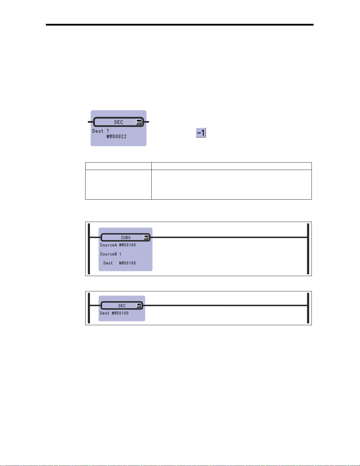
2.11 DEC Instruction (DEC)
[Outline]
The DEC instruction subtracts 1 from the designated integer or double-length integer register. For
integer registers, no underflow error occurs even if the result of subtraction is less than – 32768.
Likewise, no underflow error occur s for double-length integer registers.
[Format]
Symbol : DEC
Full Name : Decrement
Category : MATH
Icon :
2.11 DEC Instruction (DEC)
[Parameter]
Parameter Name Setting
Dest · Any integer type an d double-lengt h integer type regi ster (except f or # and
C registers)
· Any integer type and double-length integer type register with subscript
(except for # and C registers)
· Subscript register
[Program Example]
Integer type
⇔
equivalent
2-18
Page 36
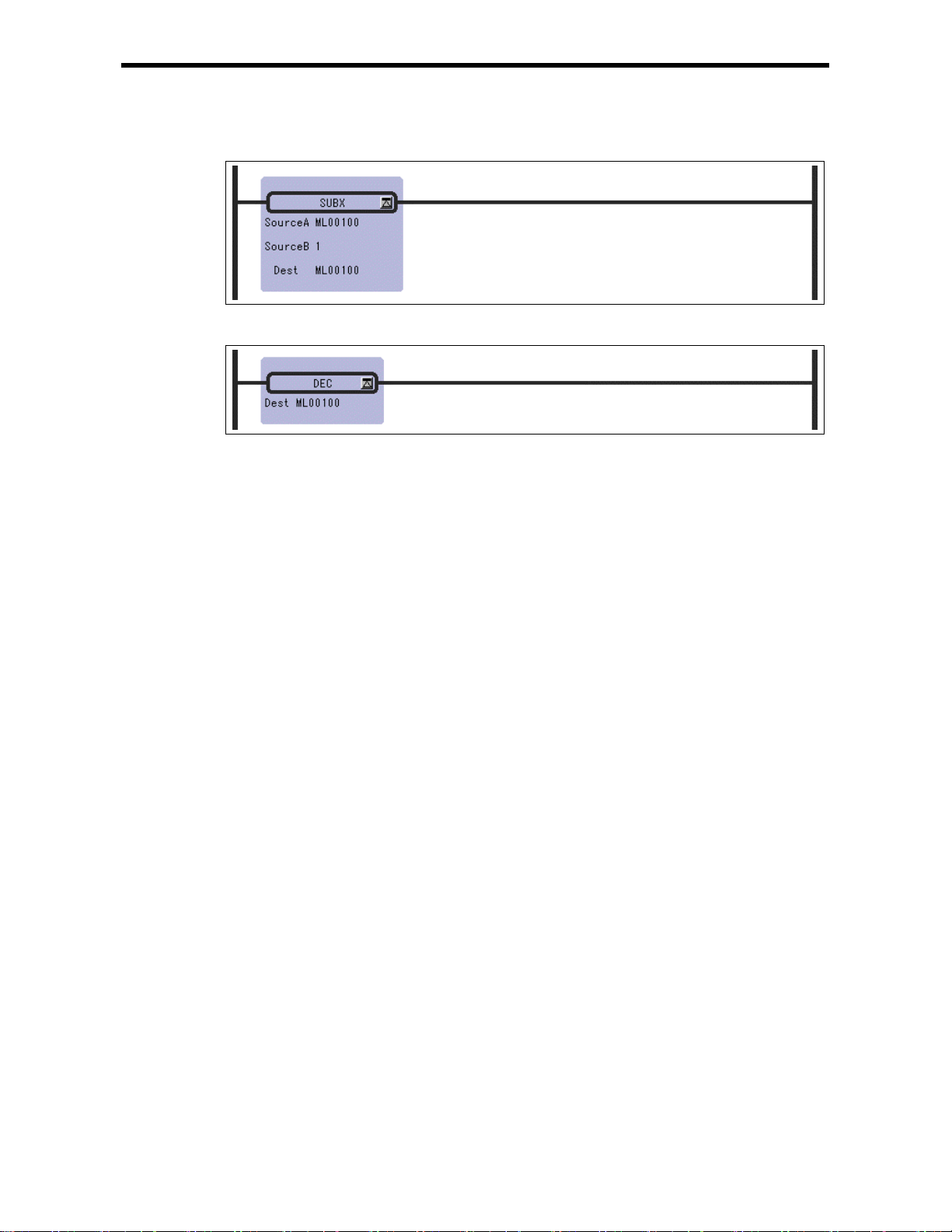
2.11 DEC Instruction (DEC)
Double-length integer type
⇔
equivalent
2-19
Page 37

2.12 ADD TIME Instruction (TMADD)
[Outline]
The TMADD instruction adds one time (hours/minutes/seconds) to another time. The Source is added
to the Dest and the result is stored in the Dest. The formats of Source and Dest are as follows.
Register Offset Data Contents Data Range (BCD)
0 Hours/minutes Upper byte (hours) : 0 to 23
1 Seconds
If the contents of the Dest and Source and the operation result are with the appropriate ranges, the
operation will be performed normally. After the operation is completed, the [Status] is turned OFF. If
the contents of the Dest and Source are outside the data ranges, the operation is not performed. In this
case, 9999H is stored in the column "second" of the Dest, and the [Status] is turned ON.
[Format]
Data Format
Lower byte (minutes) : 0 to 59
0000~0059
Sym bol : TMAD D
Full Name : Time Add
Category : MATH
Icon :
2.12 ADD TIME Instruction (TMADD)
[Parameter]
Parameter Name Setting
Source · Any integer type register
· Any integer type register with subscript
Dest · Any integer type register (except for # and C register)
· Any integer type register with subscript (except for # and C register)
[Status] · Any bit type register (except for # and C register)
· Any bit type register with subscript (except for # and C register)
* possible to omit
2-20
Page 38

2.12 ADD TIME Instruction (TMADD)
[Program Example]
The time data in DW0000 to DW00101 is added to the time data in MW00100 to MW00101.
8 hrs 40 min 32 sec + 1 hrs 22 min 16 sec = 10 hrs 2 min 48sec
(MW00100) (MW00101) (DW00000) (DW00001) (MW00100) (MW00101)
Time data Before execution After execution
MW00100 0840H 1002H
MW00101 0032H 0048H
DW00000 0122H 0122H
DW00001 0016H 0016H
2-21
Page 39
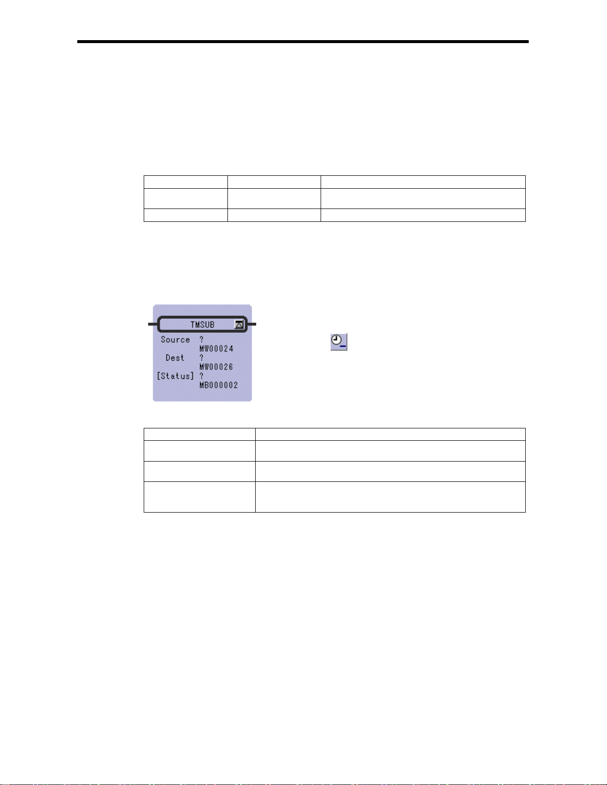
2.13 SUBTRACT TIME Instruction (TMSUB)
[Outline]
The TMSUB instruction subtracts one time (hours/minutes/seconds) from another time. The Source is
subtracted from the Dest and the result is stored in the Dest. The formats of Source and Dest are as
follows.
Data Format
Register Offset Data Contents Data Range (BCD)
0 Hours/minutes Upper byte (hours) : 0 to 23
Lower byte (minutes) : 0 to 59
1 Seconds
If the cont ents of the Dest and Source are with the appropriate ranges, the operation will be performed
normally. After the operation is completed, the [Status] is turned OFF. If the contents of the Dest and
Source are outside the data ranges, the operation is not performed. In this case, 9999H is stored in the
column "second" of the Dest, and the [Status] is turned ON.
[Format]
0000~0059
Symbol : TMSUB
Full Na m e : Time Su b
Category : MATH
Icon :
2.13 SUBTRACT TIME Ins t r uction (TMSUB)
[Parameter]
Parameter Name Setting
Source · Any integer type register
· Any integer type register with subscript
Dest · Any integer type register (except for # and C register)
· Any integer type register with subscript (except for # and C register)
[Status] · Any bit type register (except for # and C register)
· Any bit type register with subscript (except for # and C register)
* possible to omit
2-22
Page 40
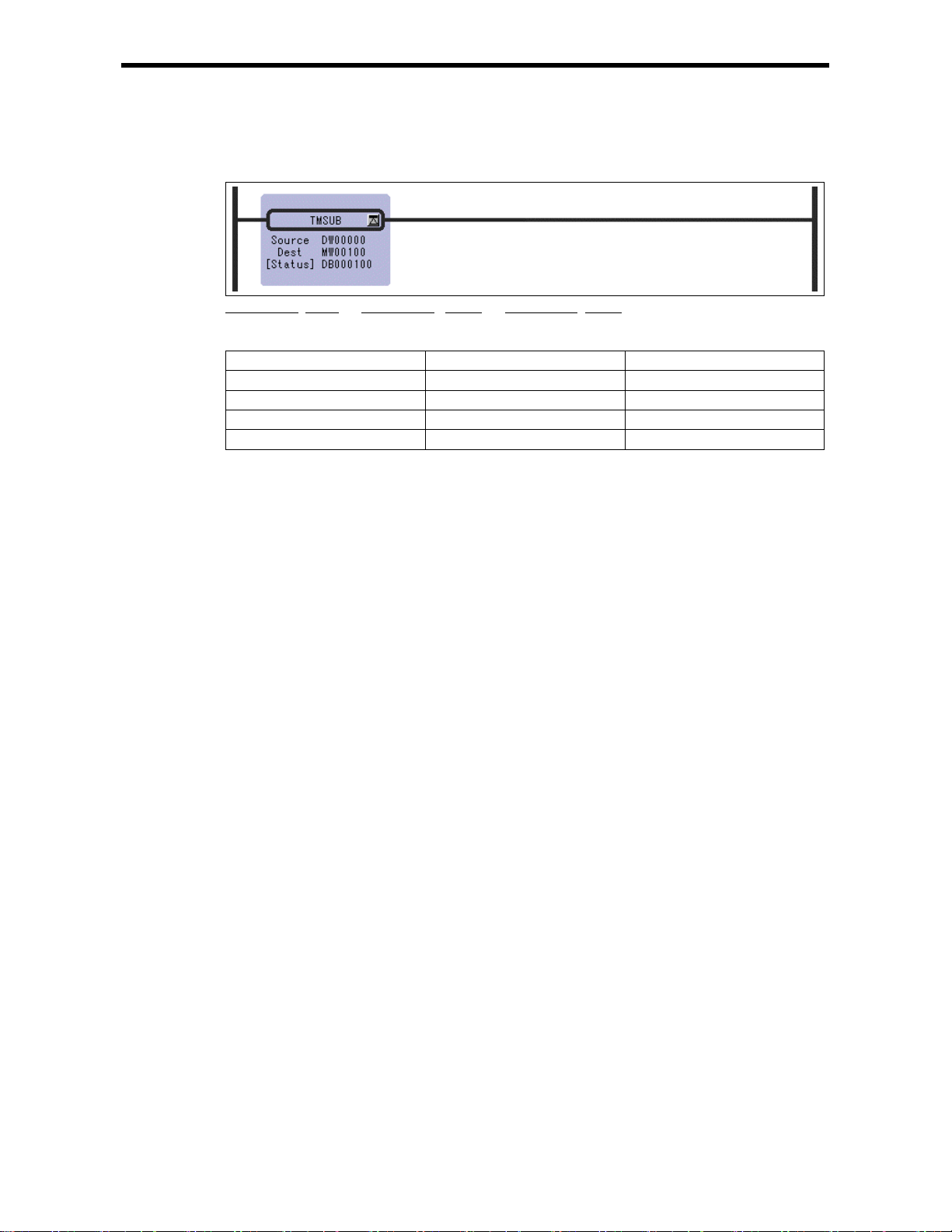
2.13 SUBTRACT TIME Ins t r uction (TMSUB)
[Program Example]
The time data in DW0000 to DW0001 is subtracted to the time data in MW00100 to MW00101.
8 hrs 40 min 32sec + 1 hrs 22 min 16 sec = 7 hrs 18 min 16 sec
(MW00100) (MW00101) (DW00000) (DW00001) (MW00100) (MW00101)
Time data Before execution After execution
MW00100 0840H 0718H
MW00101 0032H 0016H
DW00000 0122H 0122H
DW00001 0016H 0016H
2-23
Page 41
2.14 SPEND TIME Instruction (SPEND)
[Outline]
The SPEND instruction subtracts one time (year/month/day/hours/minutes/seconds) from another time
data and calculates the elapsed time. Source is subtracted from the Dest and the result is stored in the
Dest. The formats of Source and Dest are as follows.
Source Format
Register Offset Data Contents Data Range (BCD) I/O
0 Year (BCD)
1 Month/Day (BCD) Upper byte (month) : 1 to 12
2 Hours/minutes (BCD) Upper byte (hours) : 0 to 23
3 Seconds (BCD)
Dest Format
Register Offset Data Contents Data Range (BCD) I/O
0 Year (BCD)
1 Month/Day (BCD) Upper byte (month) : 1 to 12
2 Hours/minutes (BCD) Upper byte (hours) : 0 to 23
3 Seconds (BCD)
4
5
If the contents of the Dest, Source and the operation result are with the appropriate ranges, the
operation will be performed normally. After the operation is completed, [Status] is turned OFF. If the
contents of the Dest and Source are outside the data ranges, the operation is not performed. In this case,
9999H is stored in the column "second" of the Dest, and the [Status] is turned ON.
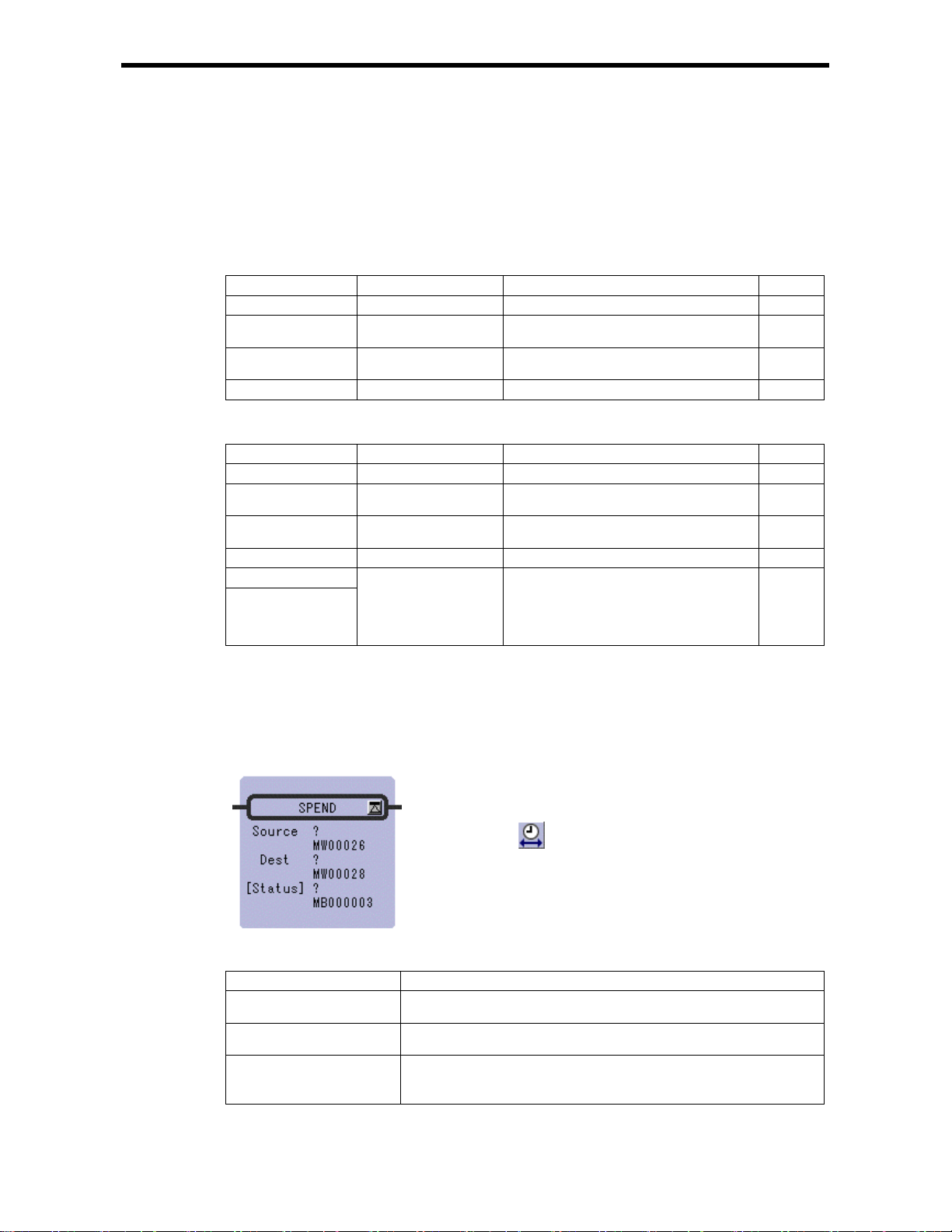
[Format]
Total number of seconds This is the number of records which is
Symbol : SPEND
Full Name : Time Spend
Category : MATH
Icon :
2.14 SPEND TIME Instruction (SPEND)
0000~0099
Lower byte (day) : 1 to 31
Lower byte (minutes) : 0 to 59
0000~0059
0000~0099
Lower byte (day) : 1 to 31
Lower byte (minutes) : 0 to 59
0000~0059
obtained by converting Year/Month/Day/
Hour/Minutes/Seconds, which is the results
of operations, to seconds. (Double-length
integer)
IN
IN
IN
IN
IN/OUT
IN/OUT
IN/OUT
IN/OUT
IN/OUT
[Parameter]
Parameter Name Setting
Source · Any integer type register
· Any integer type register with subscript
Dest · Any integer type register (except for # and C register)
· Any integer type register with subscript (except for # and C register)
[Status] · Any bit type register (except for # and C register)
· Any bit type register with subscript (except for # and C register)
* possible to omit
2-24
Page 42

2.14 SPEND TIME Instruction (SPEND)
[Program Example]
The time elapsed from the time data in MW00100 to MW00103 to the time data in DW00000 to
DW00003 is stored to MW00100 - MW00105.
98 yrs 5 mos 11 day s 15 hrs 4 min 47 sec – 98 yrs 4 m os 2 days 8 hrs 13 min 8 sec
(MW00100) (MW00101) (MW00102) (MW00103) (DW00000) (DW00101) (DW00102) (DW00103)
= 0 yrs 39 days 6 hrs 51 min 39 sec
(MW00100) (MW0010 1) (MW00102) (MW00 103)
Time data Before execution After execution
MW00100 H0098 H0000
MW00101 H0511 H0039
MW00102 H1504 H0651
MW00103 H0047 H0039
MW00104 ––
MW00105 ––
DW00000 H0098 H0098
DW00001 H0402 H0402
DW00002 H0813 H0813
DW00003 H0008 H0008
Notes: In the operation results, th e year is c ounted as 365 da ys and a lea p year is not t aken into
consideration. Also, the number of months is not counted. It is counted in days.
3394299 (Decimal)
2-25
Page 43

2.15 SIGN INVERSION Instruction (INV)
[Outline]
The INV instruction inverts the sign of the contents of the Source, and the result is stored in the Dest.
[Format]
Symbol : INV
Full Name : Inve rse
Category : MATH
Icon :
2.15 SIGN IN VERSI O N Instruction (INV)
[Parameter]
Parameter Name Setting
Source · Any integer type, double-length integer type and real number type register
· Any integer type, d ouble-lengt h integer t ype and real number t ype register
with subscript
· Subscript register
· Constant
Dest · Any integer t ype, double-len gth integer t ype and real number type register
(except for # and C registers)
· Any integer type, d ouble-lengt h integer t ype and real number t ype register
with subscript (except for # and C registers)
· Subscript register
2-26
Page 44

2.15 SIGN IN VERSI O N Instruction (INV)
[Program Example]
Integer type data
Double-length integer type data
Real number type data
2-27
Page 45

2.16 1’S COMPLEMENT Instruction (COM)
[Outline]
The COM instruction determines the 1’s complement of the contents of the Source and the result is
stored in the Dest.
[Format]
Symbol : COM
Full Name : Compleme n t
Category : MATH
Icon :
2.16 1’S COMPLEMENT Instruction (COM)
[Parameter]
Parameter Name Setting
Source · Any integer type and double-length integer type register
· Any integer type and double-length integer type register with subscript
· Subscript register
Dest · Any integer type an d double-lengt h integer type regi ster (except f or # and
C registers)
· Any integer type and double-length integer type register with subscript
(except for # and C registers)
· Subscript register
[Program Example]
Integer type data
Double-length integer type data
2-28
Page 46

2.17 ABSOLUTE VAL UE CONVERSION Inst ruction (ABS)
2.17 ABSOLUTE VALUE CONVERSION Instruction (ABS)
[Outline]
The ABS instruction determines the absolute value of the contents of the Source and the result is
stored in the Dest.
[Format]
Symbol : ABS
Full Name : Absolute
Category : MATH
Icon :
[Parameter]
Parameter Name Setting
Source · Any integer type, double-length integer type and real number type register
· Any integer type, d ouble-lengt h integer t ype and real number t ype register
with subscript
· Subscript register
Dest · Any integer t ype, double-len gth integer t ype and real number type register
(except for # and C registers)
· Any integer type, d ouble-lengt h integer t ype and real number t ype register
with subscript (except for # and C registers)
· Subscript register
2-29
Page 47

2.17 ABSOLUTE VAL UE CONVERSION Inst ruction (ABS)
[Program Example]
Integer type data
Double-length integer type data
Real number type data
2-30
Page 48
2.18 BINARY CONVERSI O N Instruction (BIN)
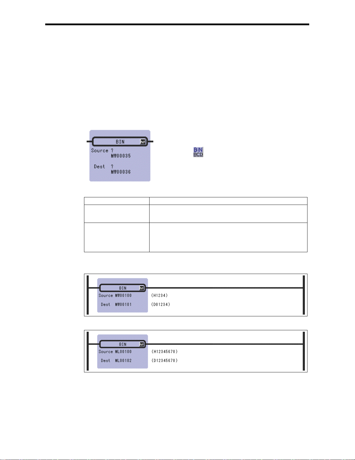
2.18 BINARY CONVERSION Instruction (BIN)
[Outline]
The BIN i nstruction c onverts a bina ry coded decima l (BCD) valu e in the Source and into a binary
value (binary conversion) and the result is stored in t he Dest. If the 4 - digit BCD value in the integer
is abcd, the output value (Dest) of the BIN instruction can be determined by the following formula:
Dest = (a x 1,000) + (b x 100) + (c x 10) + d
Although the above formula is applicable even if the value in the Source is not in BCD notation (e.g.
123FH), correct results are obtained in such case s.
[Format]
Symbol : BIN
Full Name : Convert to Binary
Category : MATH
Icon :
[Parameter]
Parameter Name Setting
Source · Any integer type and double-length integer type register
· Any integer type and double-length integer type register with subscript
· Subscript register
Dest · Any integer type an d double-lengt h integer type regi ster (except f or # and
C registers)
· Any integer type and double-length integer type register with subscript
(except for # and C registers)
· Subscript register
[Program Example]
Integer type data
Double-length in t e ge r data
2-31
Page 49

2.19 BCD CONVERSION Instruction (BCD)
[Outline]
The BCD instruction converts a binary value in the Source into a BCD value (BCD conversion) and
the result is stored in the Dest. If the 4 - digit decimal value in the Source is abcd, the output value
(Dest) of the BCD instruction can be determined by the following formula:
Dest = (a × 4096) + (b × 256) + (c × 16) + d
Although the above formula is applicable even if the value in the Source cannot be expressed in BCD
notati on (e.g. num bers greate r than 9999 or negative nu mbers), c orrec t results are obtained in s uch
cases.
[Format]
Symbol : BCD
Full Name : Convert to BCD
Category : MATH
Icon :
2.19 BCD CON VERSI O N Instructio n (BCD)
[Parameter]
Parameter Name Setting
Source · Any integer type and double-length integer type register
· Any integer type and double-length integer type register with subscript
· Subscript register
Dest · Any integer type an d double-lengt h integer type regi ster (except f or # and
C registers)
· Any integer type and double-length integer type register with subscript
(except for # and C registers)
· Subscript register
[Program Example]
Integer type data
Double-length integer type data
2-32
Page 50

2.20 PARITY CONVERSI ON Instruct ion ( PARITY)
2.20 PARITY CONVERSION Instruction (PARITY)
[Outline]
The PARITY instruction counts the number of bits in the Source that are set to ON (or 1) and the
result is stored in the Dest.
[Format]
Symbol : PARITY
Full Name : Count ON Bit
Category : MATH
Icon :
[Parameter]
Parameter Name Setting
Source · Any integer type and double-length integer type register
· Any integer type and double-length integer type register with subscript
· Subscript register
Dest · Any integer type an d double-lengt h integer type regi ster (except f or # and
C registers)
· Any integer type and double-length integer type register with subscript
(except for # and C registers)
· Subscript register
[Program Example]
Integer type data
Double-length integer type data
2-33
Page 51

2.21 ASCII CONVERSION Inst ruction ( ASCII )
2.21 ASCII CONVERSION Instruction (ASCII)
[Outline]
The ASCII instruction converts the specified characters (character string in Source) to the
corresponding ASCII character codes and stores them in the designated Dest. It recognizes uppercase
and lowercase characters separately.
The first character is stored in the lower-place byte of the first word and the second character is stored
in the higher-place byte of the first word. Other characters are stored in the same way. If the number
of characters is odd, the higher-place byte of the last word in the storage register is set to 0. Up to 32
charact ers can be entered.
[Format]
Symbol : ASCII
Full Name : Convert Character to ASCII
Category : MATH
Icon :
[Parameter]
Parameter Name Setting
Source · ASCII characters
Dest · Any integer type register (except for # and C register)
· Any integer type register with subscript (except for # and C register)
[Program Example]
The character string "ABCD" is stored in MW00100 to MW00101.
Upper Lower
MW00100
MW00101
The character string "ABCDEFG" is stored in MW00100 to MW00103.
42H ('B')
44H ('D')
41H ('A')
43H ('C')
MW00100 = 4241H
MW00101 = 4443H
Upper Lower
MW00100
MW00101
MW00102
MW00103
42H ('B')
44H ('D')
46H ('F')
00H
"0" is entered in the extra byte.
41H ('A')
43H ('C')
45H ('E')
47H ('G')
MW00100 = 4241H
MW00101 = 4443H
MW00100 = 4645H
MW00101 = 0047H
2-34
Page 52
2.22 ASCII CO N VERSI ON 2 Instru ct io n (BINASC)
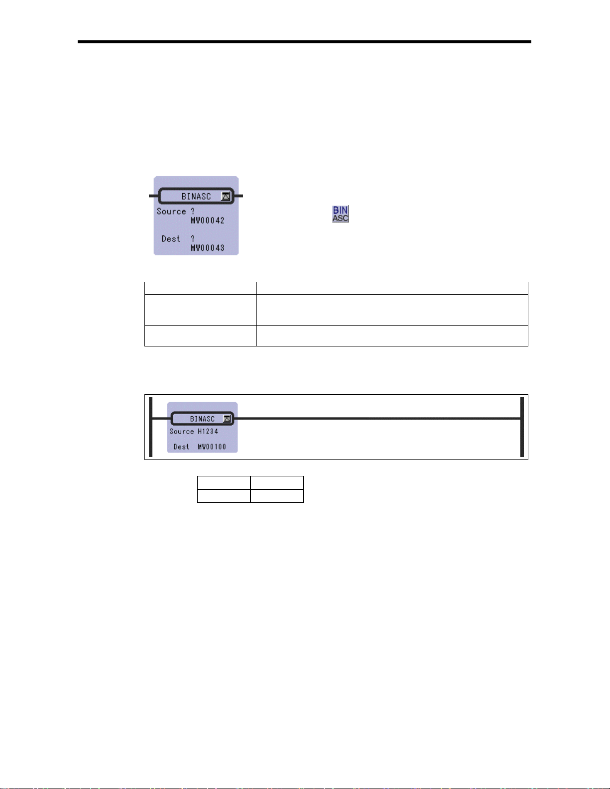
2.22 ASCII CONVERSION 2 Instruction (BINASC)
[Outline]
The BINASC instruction converts the 16-bit binary data stored in the Source into four-digit
hexadecimal ASCII character codes and stores them in the designated Dest (two words).
[Format]
Symbol : BINASC
Full Name : Convert Binary to ASCII
Category : MATH
Icon :
[Parameter]
Parameter Name Setting
Source · Any integer type register
· Any integer type register with subscript
· Constant
Dest · Any integer type register (except for # and C register)
· Any integer type register with subscript (except for # and C register)
[Program Example]
The "1234H" binary is converted to a for digit hexadecimal ASICII code and stored in MW00100 to
MW00101.
Upper Lower
MW00100
MW00101
32H ('2')
34H ('4')
31H ('1')
33H ('3')
MW00100 = 3231H
MW00101 = 3433H
2-35
Page 53

2.22 ASCII CO N VERSI ON 3 Instru ct io n (ASCBIN)
2.23 ASCII CONVERSION 3 Instruction (ASCBIN)
[Outline]
The ASCBIN instruction converts four-digit hexadecimal ASCII character codes in the Source into
16-bit binary data and stores it in the Dest.
[Format]
Symbol : ASCBIN
Full Name : Convert ASCII to Binary
Category : MATH
Icon :
[Parameter]
Parameter Name Setting
Source · Any integer type register
· Any integer type register with subscript
Dest · Any integer type register (except for # and C register)
· Any integer type register with subscript (except for # and C register)
[Program Example]
The for-byte ASCII code stored in MW00100 to MW00101 is converted to two-byte binary data, and
the result is stored in MW00200.
Source
Upper
MW00100
MW00101
32H ('2')
34H ('4')
31H ('1')
33H ('3')
MW00200
12H
LowerUpper Lower
34H
2-36
Page 54

3 Logical Operation/ Comparison Instructions
3 Logical Operation/ Comparison
Instructions
3.1 AND Instruction ( AND )
3.2 OR Instruct ion ( OR )
3.3 XOR Instruction ( XOR )
3.4 Comparison In struction ( < )
3.5 Comparison In struction ( <= )
3.6 Comparison In struction ( = )
3.7 Comparison Instruction ( != )
3.8 Comparison In struction( >= )
3.9 Comparison In struction ( > )
3.10 RANGE CHECK Instruct ion ( RCHK )
・・・・・・・・・・・・・・・・・・・・・・・・・・・・・・・・・・・・・・・・・・・・・・・・
・・・・・・・・・・・・・・・・・・・・・・・・・・・・・・・・・・・・・・・・・・・・・・・・・・
・・・・・・・・・・・・・・・・・・・・・・・・・・・・・・・・・・・・・・・・・・・・・・・
・・・・・・・・・・・・・・・・・・・・・・・・・・・・・・・・・・・・・・・・・・・・
・・・・・・・・・・・・・・・・・・・・・・・・・・・・・・・・・・・・・・・・・・・
・・・・・・・・・・・・・・・・・・・・・・・・・・・・・・・・・・・・・・・・・・・・
・・・・・・・・・・・・・・・・・・・・・・・・・・・・・・・・・・・・・・・・・・・
・・・・・・・・・・・・・・・・・・・・・・・・・・・・・・・・・・・・・・・・
・・・・・・・・・・・・・・・・・・・・・・・・・・・・・・・・・・・・・・・・・・・
・・・・・・・・・・・・・・・・・・・・・・・・・・・・・・・・・
3-2
3-3
3-4
3-5
3-6
3-7
3-8
3-9
3-10
3-11
3-1
Page 55
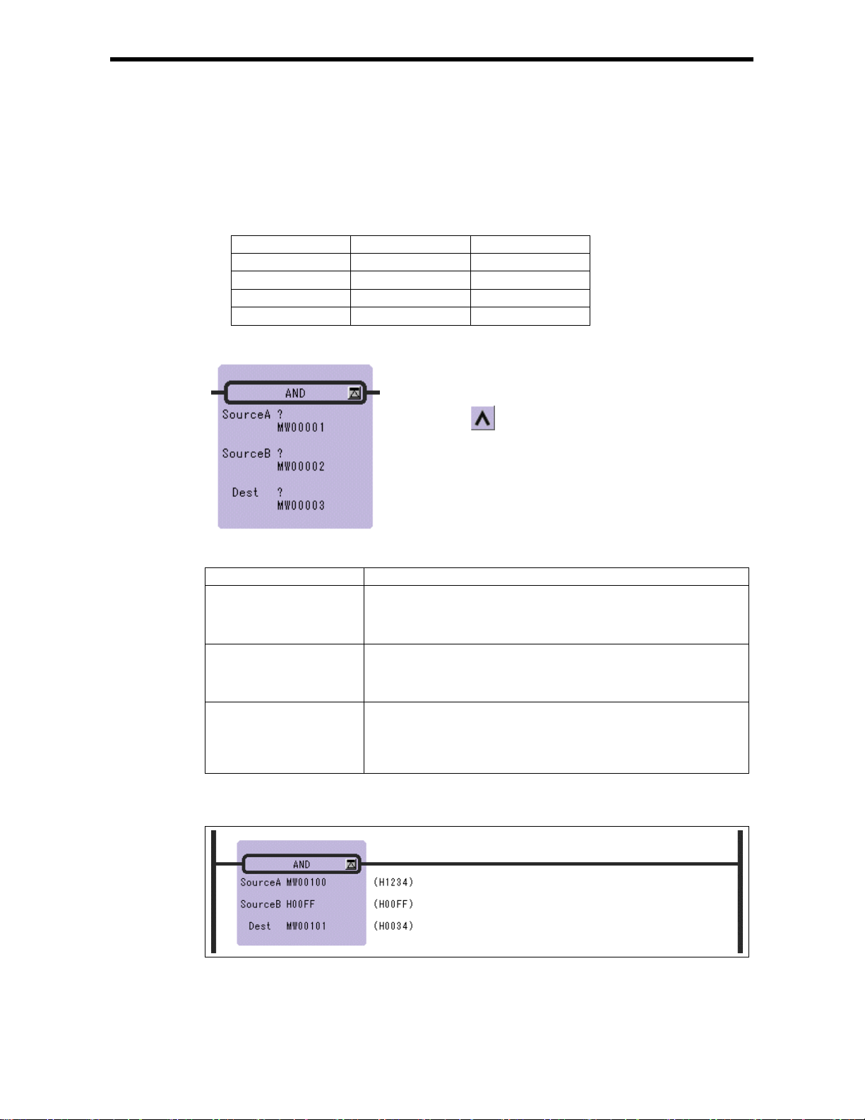
3.1 AND Instruction (AND)
[Outline]
The AND instruction outpu ts the logical product (AND) of Source A and Source B to the Dest.
1 bit Truth Table for the Logical Product
Source A Source B Dest
0 0 0
0 1 0
1 0 0
1 1 1
[Format]
Symbol : AND
Full Name : AND
Category : LOGIC
Icon :
3.1 AND Instructio n (AND)
[Parameter]
Parameter Name Setting
Source A · Any integer type and double-length integer type register
· Any integer type and double-length integer type register with subscript
· Subscript register
· Constant
Source B · Any integer type and double-length integer type register
· Any integer type and double-length integer type register with subscript
· Subscript register
· Constant
Dest · Any integer type and dou ble-length int eger type regis ter (except for # an d
C register)
· Any integer type and double-length integer type register with subscript
(except for # and C register)
· Subscript register
[Program Example]
The logical prod uct of MW000100 and a consta nt is stored in MW00101.
3-2
Page 56

3.2 OR Instruction (OR)
[Outline]
The OR instruction outputs the logical sum (OR) of Source A and Source B to the Dest.
Source A Source B Dest
0 0 0
0 1 1
1 0 1
1 1 1
[Format]
1 bit Truth Table for the Logical Sum
Symbol : OR
Full Name : Inclus ive OR
Category : LOGIC
Icon :
3.2 XOR Instruction (OR)
[Parameter]
Parameter Name Setting
Source A · Any integer type and double-length integer type register
· Any integer type and double-length integer type register with subscript
· Subscript register
· Constant
Source B · Any integer type and double-length integer type register
· Any integer type and double-length integer type register with subscript
· Subscript register
· Constant
Dest · Any integer type an d double-lengt h integer type regi ster (except f or # and
C register)
· Any integer type and double-length integer type register with subscript
(except for # and C register)
· Subscript register
[Program Example]
The logical s um of MW00100 and a c ons tant is stor ed in MW00101.
3-3
Page 57

3.3 XOR Instruction (XOR)
[Outline]
The XOR instruction output s the exclusive logical sum (XOR) of Source A and Source B to the Dest.
1 bit Truth Table for th e Exclusive Logical Sum
Source A Source B Dest
0 0 0
0 1 1
1 0 1
1 1 0
[Format]
Symbol : XOR
Full Name : Exclusive OR
Category : LOGIC
Icon :
3.3 XOR Inst ru ct ion (XOR)
[Parameter]
Parameter Name Setting
Source A · Any integer type and double-length integer type register
· Any integer type and double-length integer type register with subscript
· Subscript register
· Constant
Source B · Any integer type and double-length integer type register
· Any integer type and double-length integer type register with subscript
· Subscript register
· Constant
Dest · Any integer type an d double-lengt h integer type regi ster (except f or # and
C register)
· Any integer type and double-length integer type register with subscript
(except for # and C register)
· Subscript register
[Program Example]
The exclusive logical sum of MW 00100 and a const ant is stored in MW00101.
3-4
Page 58

3.4 Comparison Instruction (<)
[Outline]
This instruc tion compare Source A with Source B and stores the comparison result in the bit output
(the result is ON when true).
[Format]
3.4 Comparison Instruction (<)
Symbol : <
Full Name : Less Than (A < B)
Category : LOGIC
Icon :
[Parameter]
Parameter Name Setting
Source A · Any integer type, double-length integer type and real number type register
· Any integer type, d ouble-lengt h integer t ype and real number t ype register
with subscript
· Subscript register
· Constant
Source B · Any integer type, double-length integer type and real number type register
· Any integer type, d ouble-lengt h integer t ype and real number t ype register
with subscript
· Subscript register
· Constant
[Program Example]
If the value of MW00100 is smaller than 100, after the instructions operation are executed.
3-5
Page 59
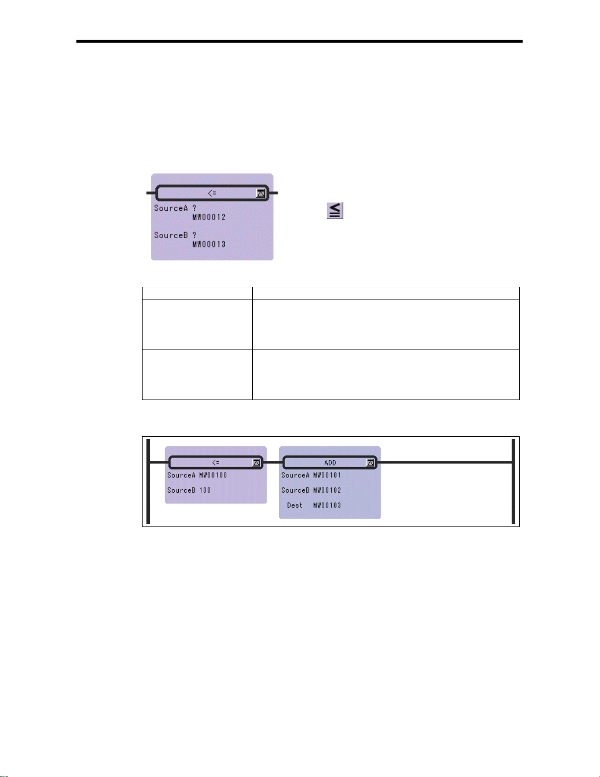
3.5 Comparison Instruction (<=)
[Outline]
This instruc tion compare Source A with Source B and stores the comparison result in the bit output
(the result is ON when true).
[Format]
3.5 Comparison Instruction (<=)
Symbol : <=
Full Name : Less Than or Equal (A<=B)
Category : LOGIC
Icon :
[Parameter]
Parameter Name Setting
Source A · Any integer type, double-length integer type and real number type register
· Any integer type, d ouble-lengt h integer t ype and real number t ype register
with subscript
· Subscript register
· Constant
Source B · Any integer type, double-length integer type and real number type register
· Any integer type, d ouble-lengt h integer t ype and real number t ype register
with subscript
· Subscript register
· Constant
[Program Example]
If the value of MW00100 is under 100, after the instructi ons operation are ex ecut ed.
3-6
Page 60

3.6 Comparison Instruction (=)
[Outline]
This instruc tion compare Source A with Source B and stores the comparison result in the bit output
(the result is ON when true).
[Format]
Symbol : =
Full Name : Equal (A = B)
Category : LOGIC
Icon :
3.6 Comparison Instruction (=)
[Parameter]
Parameter Name Setting
Source A · Any integer type, double-length integer type and real number type register
· Any integer type, d ouble-lengt h integer t ype and real number t ype register
with subscript
· Subscript register
· Constant
Source B · Any integer type, double-length integer type and real number type register
· Any integer type, d ouble-lengt h integer t ype and real number t ype register
with subscript
· Subscript register
· Constant
[Program Example]
If the value of MW00100 is equal to 100, after the instructions operation are executed.
3-7
Page 61

3.7 Comparison Instruction (!=)
[Outline]
This instruc tion compare Source A with Source B and stores the comparison result in the bit output
(the result is ON when true).
[Format]
3.7 Comparison Instruction (!=)
Symbol : !=
Full Name : Not Equal (A!= B)
Category : LOGIC
Icon :
[Parameter]
Parameter Name Setting
Source A · Any integer type, double-length integer type and real number type register
· Any integer type, d ouble-lengt h integer t ype and real number t ype register
with subscript
· Subscript register
· Constant
Source B · Any integer type, double-length integer type and real number type register
· Any integer type, d ouble-lengt h integer t ype and real number t ype register
with subscript
· Subscript register
· Constant
[Program Example]
If the value of MW00100 is not equal to 10 0, after th e ins tructions operation are executed.
3-8
Page 62

3.8 Comparison Instruction (>=)
[Outline]
This instruc tion compare Source A with Source B and stores the comparison result in the bit output
(the result is ON when true).
[Format]
3.8 Comparison Instruction (>=)
Symbol : >=
Full Name : Greater Than or Equal (A >=B)
Category : LOGIC
Icon :
[Parameter]
Parameter Name Setting
Source A · Any integer type, double-length integer type and real number type register
· Any integer type, d ouble-lengt h integer t ype and real number t ype register
with subscript
· Subscript register
· Constant
Source B · Any integer type, double-length integer type and real number type register
· Any integer type, d ouble-lengt h integer t ype and real number t ype register
with subscript
· Subscript register
· Constant
[Program Example]
If the value of MW00100 is above 100, after the instructions operation are executed.
3-9
Page 63

3.9 Comparison Instruction (>)
[Outline]
This instruc tion compare Source A with Source B and stores the comparison result in the bit output
(the result is ON when true).
[Format]
3.9 Comparison Instruction (>)
Symbol : >
Full Name : Greater Than (A > B)
Category : LOGIC
Icon :
[Parameter]
Parameter Name Setting
Source A · Any integer type, double-length integer type and real number type register
· Any integer type, d ouble-lengt h integer t ype and real number t ype register
with subscript
· Subscript register
· Constant
Source B · Any integer type, double-length integer type and real number type register
· Any integer type, d ouble-lengt h integer t ype and real number t ype register
with subscript
· Subscript register
· Constant
[Program Example]
If the value of MW00100 is bigger than 100, after the instructions operation are executed.
3-10
Page 64
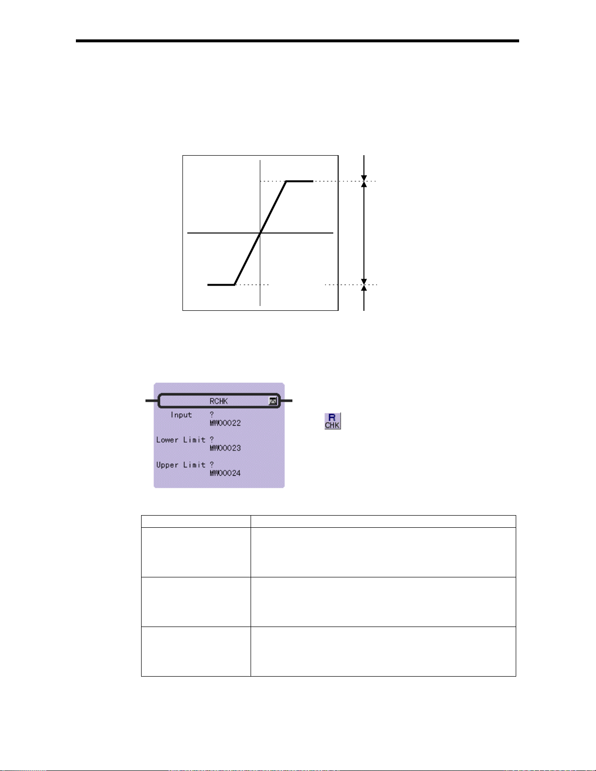
3.10 RANGE CHECK Instruction (RCHK)
[Outline]
The RCHK instruction checks whether the input value in the Input is within the Lower Limit and
Upper Limit, and then outputs the result to the bit output. The con tents of the Input are retained.
Upper Limit
3.10 RANGE CHECK Instru ctio n (RCHK)
Bit Output=OFF
Input
Bit Output=ON
Lower Limit
Bit Output=OFF
If the Input value(
Input) is greater than the Lower Limit and less than the Upper Limit, the
result(Bit Output) = ON.
• In the cases other than the above, the result(Bit Output) = OFF.
[Format]
Symbol : RCHK
Full Name : Range Check
Categor y : LOGIC
Icon :
[Parameter]
Parameter Name Setting
Input · Any integer type, double-length integer type and real number type register
· Any integer type, d ouble-lengt h integer t ype and real number t ype register
with subscript
· Subscript register
· Constant
Lower Limit · Any integer type, double-length integer type and real number type register
· Any integer type, d ouble-lengt h integer t ype and real number t ype register
with subscript
· Subscript register
· Constant
Upper Limit · Any integer type, double-length integer type and real number type register
· Any integer type, d ouble-lengt h integer t ype and real number t ype register
with subscript
· Subscript register
· Constant
3-11
Page 65

3.10 RANGE CHECK Instru ctio n (RCHK)
[Program Example]
Integer type data
-1000>MW00100 OFF
-1000<=MW00100<=1000 ON
MW00100>1000 OFF
Double-length integer type data
Input (MW00100) Output (DB000000)
Input (ML00100) Output (DB000000)
-100000>ML00100 OFF
-100000<=ML00100<=100000 ON
ML00100>100000 OFF
Real number type data
Input (DF00100) Output (DB000000)
-10.5>DF00100 OFF
-10.5<=DF00100<=10.5 ON
DF00100>10.5 OFF
3-12
Page 66

4 Program Control Instructions
4 Program Control Instructions
4.1 SUB-DRAWING CALL Instruction (SEE)
4.2 FUNCTION CA LL Instruction (FUNC)
4.3 DIRECT INPUT STRING Instruction (INS)
4.4 DIRECT OUTPUT STRING Instruction (OUTS)
4.5 EXTENSION PROGRAM CALL Instruction (XCALL)
4.6 WHILE Instruction (WHILE, END_WHILE)
4.7 IF Instruction (IF, END_IF)
4.8 IF Instruction (IF, ELSE, END_IF)
4.9 FOR Instruction (FOR, END_FOR )
4.10 EXPRESSION Instruction (EXPRESSION)
・・・・・・・・・・・・・・・・・・・・・・・・・・・・・・・・・・・・・・・・・・・・
・・・・・・・・・・・・・・・・・・・・・・・・・・・・・・・・・
・・・・・・・・・・・・・・・・・・・・・・・・・・・・・・・・・・・
・・・・・・・・・・・・・・・・・・・・・・・・・・・・・・・
・・・・・・・・・・・・・・・・・・・・・・・・・・・
・・・・・・・・・・・・・・・・・・・・・・
・・・・・・・・・・・・・・・・・・・・・・・・・・・・・・
・・・・・・・・・・・・・・・・・・・・・・・・・・・・・・・・・・・・・・
・・・・・・・・・・・・・・・・・・・・・・・・・・・・・・・・・・・・・
・・・・・・・・・・・・・・・・・・・・・・・・・・・・
4-2
4-3
4-5
4-7
4-9
4-10
4-12
4-13
4-15
4-17
4-1
Page 67

4.1 SUB-DRAWING CALL Instruction (SEE)
[Outline]
The SEE instruction is used to call a sub-drawing from a drawing or to call a sub-sub- drawing from a
sub-dr awing. Calli ng is not possi ble between dr awings of dif ferent types . For example , SEE H01
cannot be specified in DWG.L.
[Format]
Symbol : SEE
Full Name : Call Program
Category : CONTROL
[Parameter]
Parameter Name Setting
Name Program Name
[Program Example]
SEE A01
DWG.A
SEE A01
Icon :
Start of execution of
child drawing A01
End of execution of
child drawing A01
4.1 SUB-DRAWING CALL Inst ruction (SEE)
DWG.A01
DEND
4-2
Page 68

4.2 FUNCTION CALL Instruc tion (FUNC)
[Outline]
The FU N C instruc tion is use d to call a us er funct io n or syste m f u nc tion fr om a dr a w i n g, s ub - drawing,
or user function. The user function to be called must be defined in advance. (System functions do not
have to be defined by the user because they are already defined by the system.)
[Format]
Symbol : FUNC
Full Name : User Function
Category : CONTROL
Icon :
[Parameter]
Parameter Name Setting
Name Program name
INPUT Input parameter (the data type depends on function definition)
ADRESS Address parameter (Address type register)
OUTPUT Output parameter (the data type depends on function definition)
The forms of parameter input and output a r e shown in below .
Input Data Form Input Designation Description
Bit input B-VAL
I-VAL
Integer type
input
I-REG
L-VAL
Double-length
integer type input
L-REG
F-VAL
Real number
type input
F-REG
Address input ––
Designates the output to be of a bit type. Th e bit type data become th e
input to the function.
Designates the input to be of an integer type. The contents (integer
data) of the register with the designated numb er become the input to the
function.
Designates the input to be the contents of an integer type register. The
number of the integer type register is designated when referencing the
function. The contents ( integer data ) of th e regis ter w ith the d esi gnat ed
number become the input to the function.
Designates the input to be of a double-length integer type register.
When reference the fu nction, the contents (double-length in teger data)
of the register with the designated number become the input to the
function.
Designates the input to be the contents of a dou ble-length integer t ype
register. When reference the function, the contents (double-length
integer data) of the register with the designated number become the
input to the function.
Designates the input to be of a real number type. The contents (real
number data) of the r egister with the designa ted number become the
input to the function.
Designates the input to be the co ntents of a real number type register.
The number of the real number type register is designated when
referencing the function. The contents (real number data) of the
register with the designated number become the input to the function.
Hands over the address of the designa ted register (an arbitrary integer
register) to the function. Only 1 input is allow ed in the case of a user
function.
4.2 FUNCTION CALL I nstruction (FUNC)
4-3
Page 69
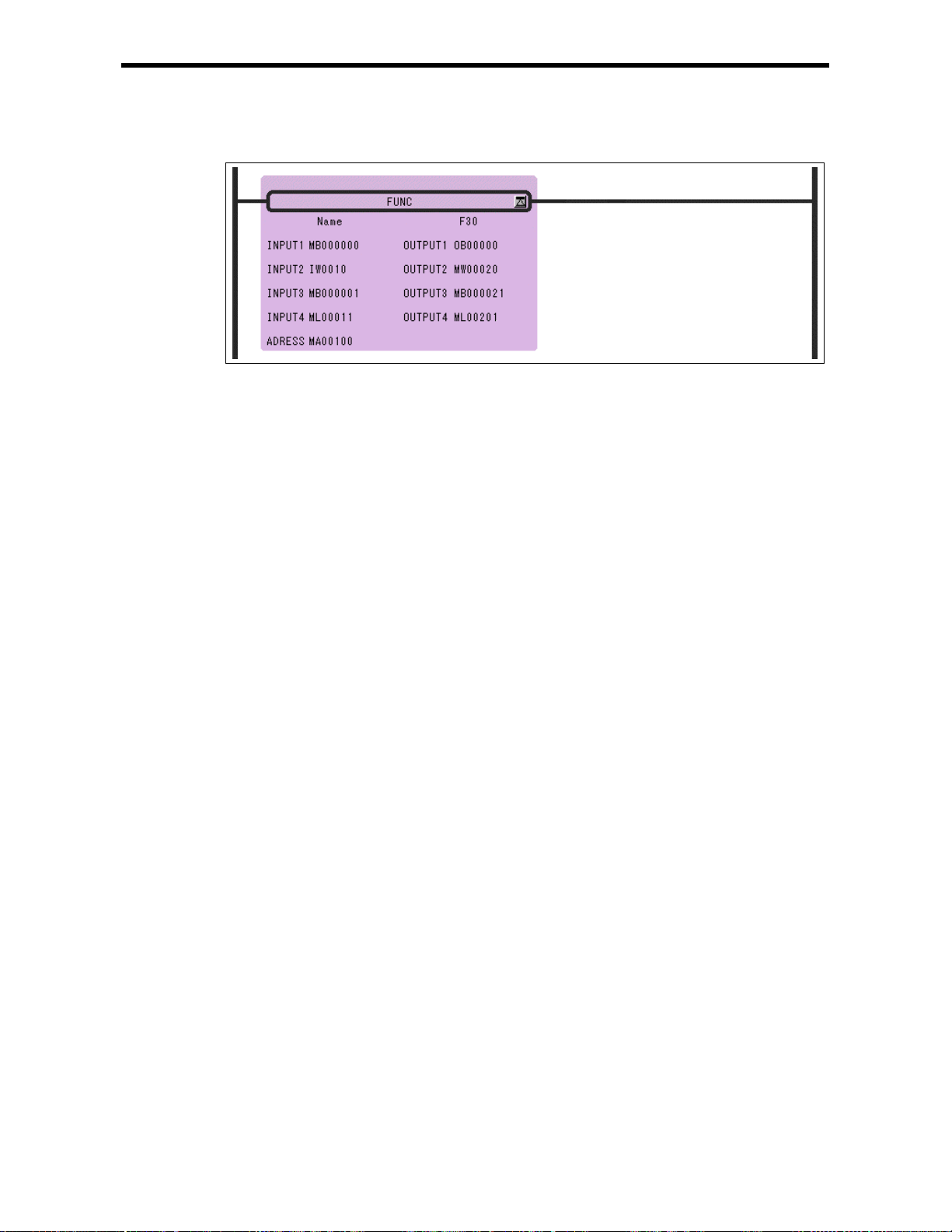
4.2 FUNCTION CALL I nstruction (FUNC)
[Program Example]
4-4
Page 70
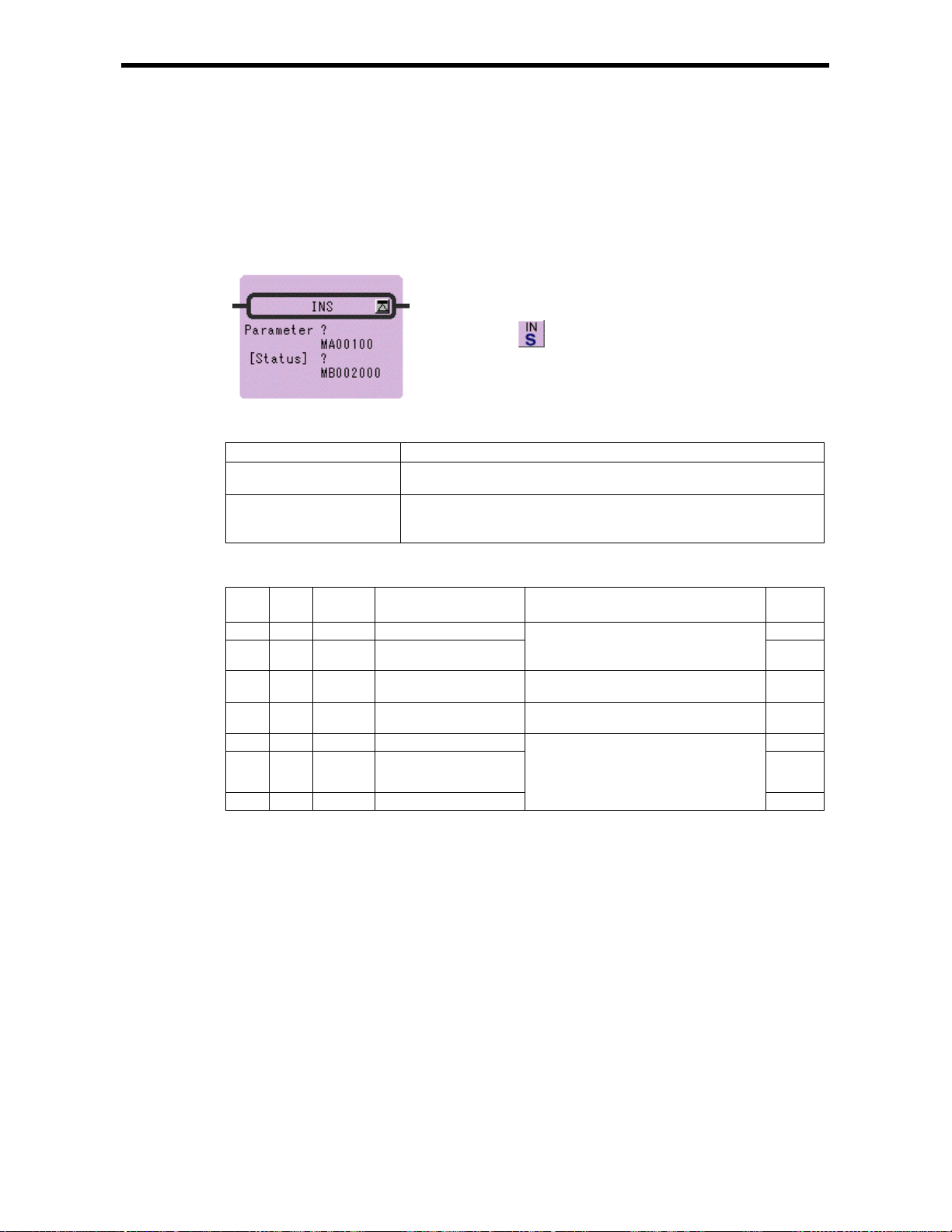
4.3 DIRECT INPUT STRING Instruction (INS)
[Outline]
The INS instruction continuously performs direct input to a single module according to the contents of
a previously-set parameter t able. INS can only be used for LIO modules.
[Format]
Symbol : INS
Full Name : Direct Input String
Category : CONTROL
Icon :
4.3 INPUT STRAIGHT I nstruction ( I NS)
[Parameter]
Parameter Name Setting
Parameter · R egister address (except for # and C registers)
· Register address with subscript
[Status] · Any bit type register (except for # and C registers)
· Any bit type register with subscript
* possible to omit
INS Instruction Parameter/Data
ADR Type Symbol Name Specifications Input or
Output
0 W RSSEL Module designation 1 IN
1 W MDSEL Module designation 2
2 W STS Status Output of a bit equivalence of the status
3 W N Number of words Designation of number of continuous
4 W ID1 Input data 1 OUT
・・・ ・・・
N+3 W IDN Input data N
・・・
・・・
Designation of module for performing
input<For details refer to (1) and (2)
below>
for each word input
input words
If there is an error in the output of input
data, 0 is stored
IN
OUT
IN
・・・
OUT
Method of setting RSSEL
Designates the rack/slot where the target module is mounted.
Hexadecimal expression: xxyyH
xx=rack number(01H≦xx≦04H)
yy=slot number(00H≦yy≦0DH)
(The rack number = 1, slot number = 3 with tixation in MP930)
4-5
Page 71

Method of setting MDSEL
FC840
a b c d Hexadecimal: abcdH
4.3 INPUT STRAIGHT I nstruction ( I NS)
a:Input module type
b:Rack number (1≦b≦4)
c:Slot number (1≦c≦9)
d:Data offset (0≦d≦7)
(The input module type = 0, rack number = 1, slot number = 3,
data offset = 0 with fixation in MP930)
0:Discrete input module
1:Register input module
[Program Example]
Data inpu t from LIO mounted at rack 2, slot 4.
4-6
Page 72
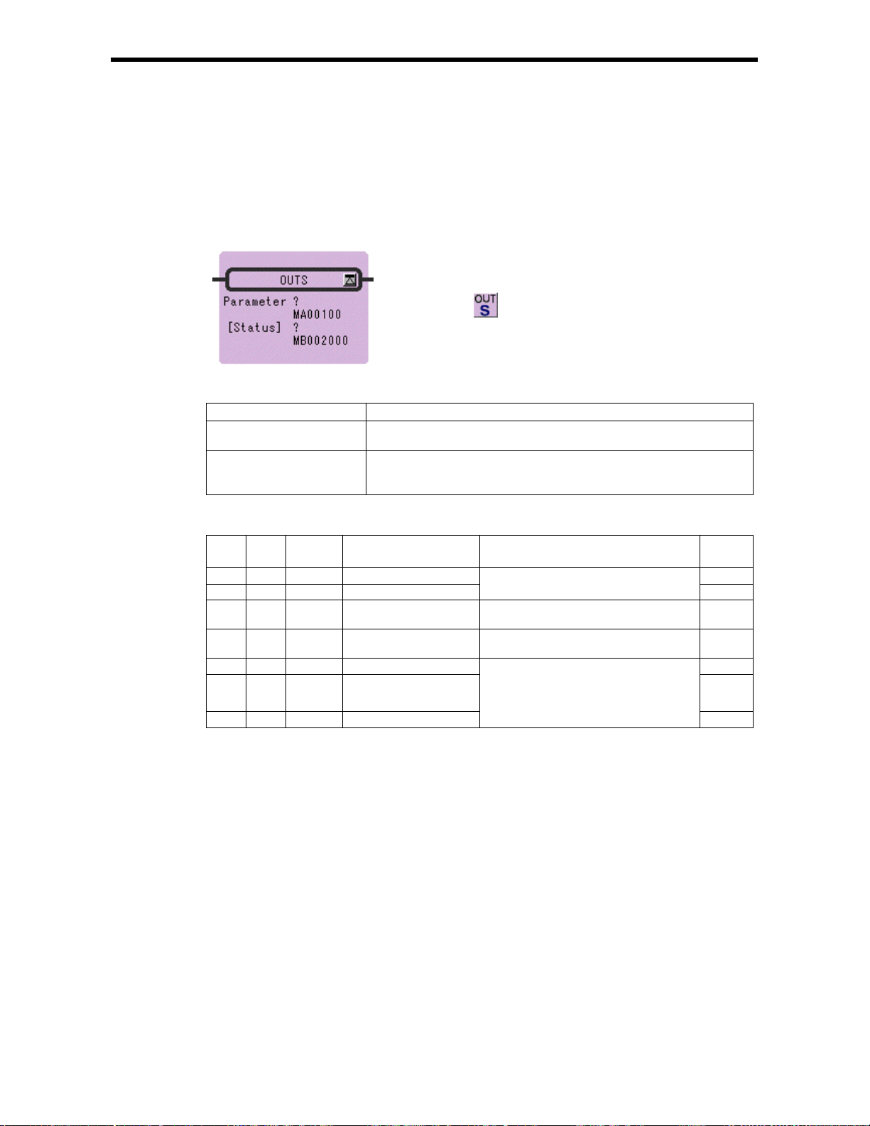
4.4 OUTPUT STRAIG HT I n st r uction (OUTS)
4.4 DIRECT OUTPUT STRING Instruction (OUTS)
[Outline]
The OUTS instruction continuously performs direct output to a single module according to the
contents of a previously-set parameter table. OUTS can only be used for LIO modules .
[Format]
Symbol : OUTS
Full Name : Direct Output String
Category : CONTROL
Icon :
[Parameter]
Parameter Name Setting
Parameter · R egister address (except for # and C registers)
· Register address with subscript
[Status] · Any bit type register (except for # and C registers)
· Any bit type register with subscript
* possible to omit
OUTS Instruction Parameter/Data
ADR Type Symbol Name Specifications Input or
Output
0 W RSSEL Module designation 1 IN
1 W MDSEL Module designation 2
2 W STS Status Output of a bit equivalence of the status
3 W N Number of words Designation of number of words output
4 W OD1 output data 1 IN
・・・ ・・・
N+3 W ODN output data N
・・・
*
Method of setting RSSEL and N (number of words) is the same as for INS.
・・・
Designation of module for performing
output*
for each word output
continuously
Setting output data
IN
OUT
IN
・・・
IN
4-7
Page 73

4.4 OUTPUT STRAIG HT I n st r uction (OUTS)
[Program Example]
Two words output to LIO-01 mounted at rack 3, slot 10.
Notes: Two outputs will be done by using the OUTS instruction becaus e local I/O is alloca ted by
default for MP930.
4-8
Page 74

4.5 EXTENSION PROGRAM CALL Instruction (XCALL)
4.5 EXTENSION PROGRAM CALL Instr uction (XCALL)
[Outline]
The XCALL instruction is used to call an extension program. E xtension programs are table format
programs. Although a pulurality of XCALL instructions may be used in one drawing, the same
extension p r ogram cannot be called more than once.
[Format]
Symbol : XCALL
Full Name : Call Extend ed Program
Category : CONTROL
Icon :
[Parameter]
Parameter Name Setting
Name
MCTBL:Constant table (M register)
IOTBL:I/O conversion table
ILKTBL:Interlock table
ASMTBL:Parts composition table
[Program Example]
DWG.x.xx
XCALL
ILKTBL
Expansion Conversion Program
XCALL ILKTBL
XPEND
The converted ladder
program cannot be
viewed at the CP-717.
4-9
Page 75
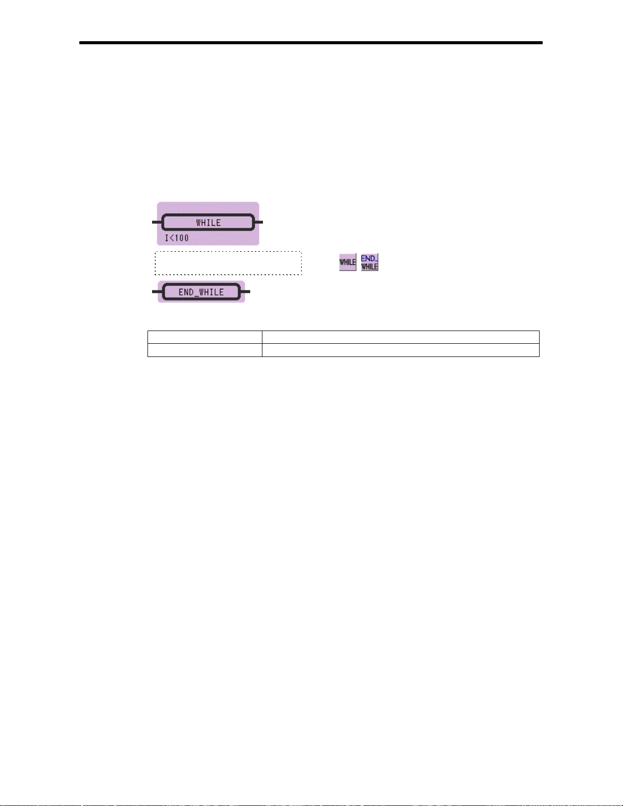
4.6 WHILE Instruction (WHILE, END_WHILE)
[Outline]
Instruction between WHILE and END_WHILE is repeatedly executed as long as the condition
specified by WHILE instruction is satisfied. When the condition is no longer satisfied, instruction
sequence is not executed and the program proceeds with the instruction immediately after
END_WHILE.
[Format]
Symbol : WHILE
END_WHILE
Full Name : While Do
Instruction Sequence
Category : CONTROL
Icon :
,
4.6 WHILE Instruction (WHILE, END_WHILE)
End of While
[Parameter]
Parameter Name Setting
Conditional Expression Description by Expression
4-10
Page 76

4.6 WHILE Instruction (WHILE, END_WHILE)
[Program Example]
The total for 100 registers, from MW00100 to MW00199, i s stored in MW00200.
4-11
Page 77

4.7 IF Instruction (IF, END_IF)
[Outline]
If the conditional expression in the IF instruction is approved, the instruction sequence between IF and
END_IF is executed. If the conditional expression in the IF instruction is not approved, the instruction
sequence between IF and END_IF is not executed.
[Format]
Instruction Sequence
4.7 IF Instruction (IF, END_IF)
Symbol : IF
END_IF
Full Name : If Then
Category : CONTROL
Icon :
End of If
,
[Parameter]
Parameter Name Setting
Conditional Expression Description by Expression
[Program Example]
If MB000108 is ON, MW00201 is added to MW00200, and MW00201 is increm ented.
4-12
Page 78

4.8 IF Instruction (IF, ELSE, END_IF)
[Outline]
If the conditional expression in the IF instruction is approved, the instruction sequence 1 between IF
and ELSE is executed. If the conditional expression in the IF instruction is not approved, the
instruction sequence 2 between ELSE and END_IF is executed.
[Format]
Instruction Sequence 1
Instruction Sequence 2
Symbol : IF
ELSE
END_IF
Full Name : If Then
Else
End of If
Category : CONTROL
Icon :
, ,
4.8 IF Instruction (IF, ELSE, END_IF)
[Parameter]
Parameter Name Setting
Conditional Expression Description by Expression
4-13
Page 79

4.8 IF Instruction (IF, ELSE, END_IF)
[Program Example]
MW00011 is set to 0 if MW00010 is positive number, and set to 1 if MW00010 is negative number.
4-14
Page 80

4.9 FOR Instruction ( FOR, END_FOR)
[Outline]
The instruction sequence surrounded by the FOR instruction and the corresponding END_FOR
instruction are executed by the number of times. Variable starts from initial value (Init) and is
incremented by Step on each execution. The instruction sequence is ended when Variable > Max
[Format]
Symbol : FOR
END_FOR
Full Name : For
End of For
Category : CONTROL
Icon :
,
4.9 FOR Inst ruction (FOR, END_FOR)
[Parameter]
Parameter Name Setting
Variable
Init
Max
Step
・Any integer type register
・Any integer type register with subscript
・Subscript register (I and J registers)
・Any integer type register
・Any integer type register with subscript
・
Subscript register
・Constant
・Any integer type register
・Any integer type register with subscript
・Subscript register
・Constant
・Any integer type register
・Any integer type register with subscript
・Subscript register
・Constant
4-15
Page 81
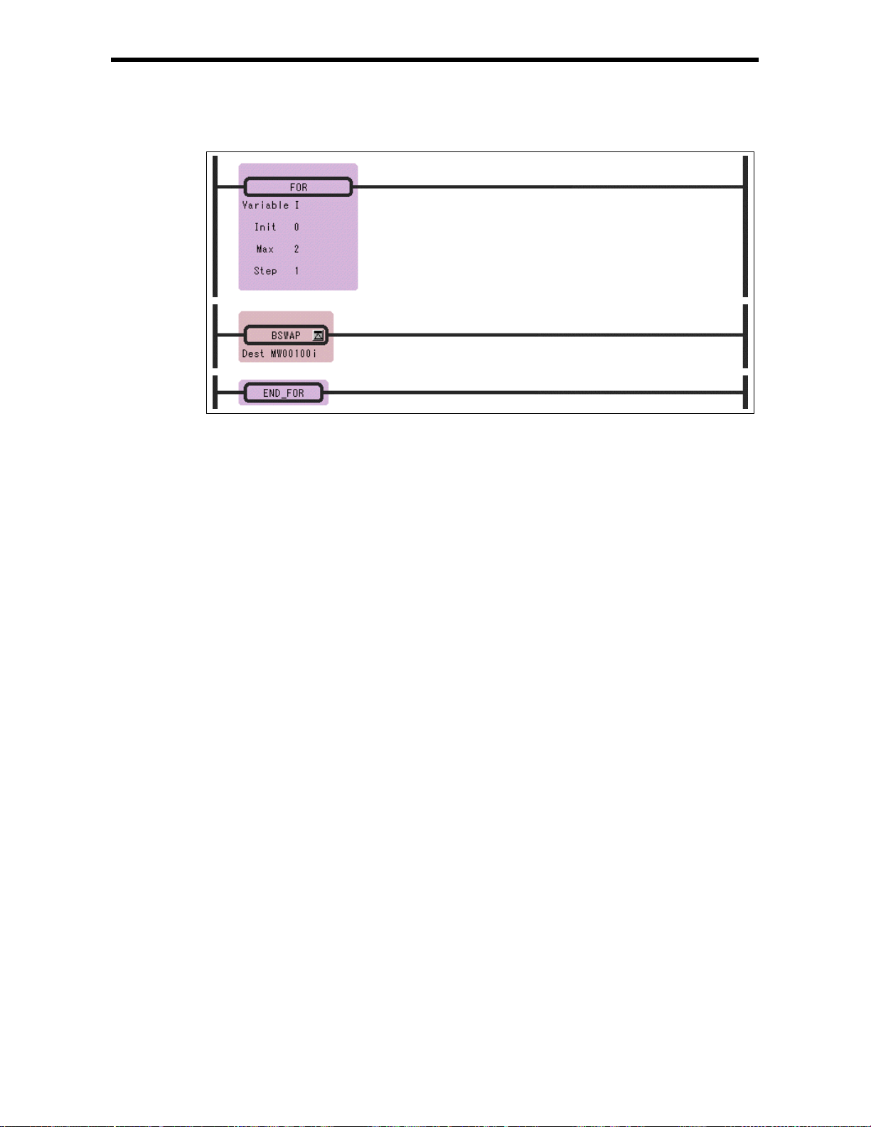
4.9 FOR Inst ruction (FOR, END_FOR)
[Program Example]
The high by t e and lo w byte, form MW00100 to MW 00102, are exchanged.
4-16
Page 82

4.10 EXPRESSI ON Instruc t ion (EXPRESSION)
4.10 EXPRESSION Instruction (EXPRESSION)
[Outline]
EXPRESSION instruction is composed by one block. It considers on a par with a coil type component,
and an input line has the Instruction of Enable/Disable command. In the block, Expression box for an
operation formula description is prepared, and the description of the operation formula to 1000 lines is
possible.
[Format]
Symbol : EXPRESSION
Full Name : Expression
Category : CONTROL
Icon :
[Parameter]
Parameter Name Setting
Conditional Expression Description by Expression
[Program Example]
4-17
Page 83

5 Basic Function Instructions
5 Basic Function Instruct ions
5.1 SQUARE ROOT Instruction (SQRT)
5.2 SINE Instruction (SIN)
5.3 COSINE Instruction (COS)
5.4 TANGENT Instruction (TAN)
5.5 ARC SINE Instruction (ASIN)
5.6 A R C COSINE Instruction (A COS )
5.7 A RC TANGENT Ins tr uc t i on (ATAN)
5.8 EXPONENT Instruction (EXP)
5.9 NATURAL LOGARITHM Instruction (LN)
5.10 COMMON LOGARITHM Instruction (LOG)
・・・・・・・・・・・・・・・・・・・・・・・・・・・・・・・・・・・・・・・・・・・・・・・・・
・・・・・・・・・・・・・・・・・・・・・・・・・・・・・・・・・・・・・・・・・・・・・
・・・・・・・・・・・・・・・・・・・・・・・・・・・・・・・・・・・・・・・・・・・・
・・・・・・・・・・・・・・・・・・・・・・・・・・・・・・・・・・・・・・・・・・・
・・・・・・・・・・・・・・・・・・・・・・・・・・・・・・・・・・・・
・・・・・・・・・・・・・・・・・・・・・・・・・・・・・・・・・・・・・・
・・・・・・・・・・・・・・・・・・・・・・・・・・・・・・・・・・・・・
・・・・・・・・・・・・・・・・・・・・・・・・・・・・・・・・・・・・・・・・・
・・・・・・・・・・・・・・・・・・・・・・・・・・・・・・・・
・・・・・・・・・・・・・・・・・・・・・・・・・・・・
5-2
5-4
5-6
5-8
5-9
5-10
5-11
5-13
5-14
5-15
5-1
Page 84

5.1 SQUARE ROOT Instruction (SQRT)
[Outline]
The SQRT instruction calculates the square root of an integer or real number value as the operation
result. The input units and output results for integer and real number values are different. This
instruct ion cannot be used for double-length integer data .
Integer Type Data
The squa re root of Source is stored in Dest. The operation result of the SQ RT instruction slightly
differs from the square root in mathematical terms. To be more precise, the operation result is
expressed by the following formula:
32768* sign (A)*SQRT (|A|/ 32768)
sign (A):sign of the S ource
|A| :absolute value of the Source
In other words, the operation result is equal to the mathematical square root multiplied by
approximately 181.02. If the input is a negative value, the square root of the absolute value is
calcula ted first and then the nega tive value of the squ are root is output a s t h e operation res ult.
The maximum error of the output value is +/-2.
Real Num ber Type Data
The square root of Source is stored in Dest. If the input is a negative value, t he square root of th e
absolute value is calculated first and then the negative value of the square root is output as the
operation result. This instruction can be used in a real number operation.
[Format]
Symbol : SQRT
Full Name : S quare Root
Category : FUNCTION
Icon :
5.1 SQUARE ROOT Instruction (SQRT)
[Parameter]
Parameter Name Setting
Source
(Input)
Dest
(Output)
· Any integer type and real number type register
· Any integer type and real number type register with subscript
· Subscript register
· Constant
· Any integer type and real number type register (except for # and C
registers)
· Any int eger type an d real number type register w ith subscr ipt (exc ept for #
and C registers)
· Subscript register
5-2
Page 85

5.1 SQUARE ROOT Instruction (SQRT)
[Program Example]
Integer type data
•
When the input is a positive number
•
When the input i s a negative number
Real number type data
• When the input is a positive number
• When the inp u t is a negative number
5-3
Page 86
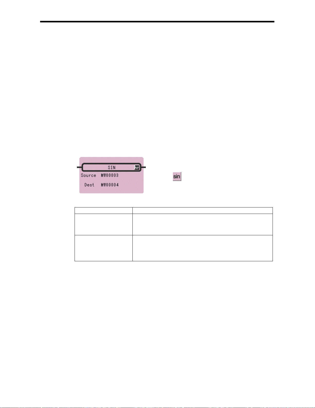
5.2 SINE Instruction (SIN)
[Outline]
The SIN instruction calculates the sine of an integer or real number value as the operation result. The
input units and output results for integer and real number values are different. This instruction
cannot be us ed for double-length int eger data.
Integer Type Data
This instruction can be used between -327.68 and 327.67 degrees. The Source is used as the input (1
= 0.01 degree) and the operation result is stored in the Dest. Upon output, the operation result is
multiplied by 10,000.
If a value outside the range of -327.68 to 327.67 is entered, the correct result cannot be obtained. For
example, if 360.00 is entered, -295.36 degre es will be output as the result.
Real Num ber Type Data
The Source is used as the input (unit = degrees) and the sine of the input is stored in the Dest.
[Format]
Symbol : SIN
Full Na m e : Sine
Category : FUNCTION
Icon :
5.2 SINE Instructio n (SIN)
[Parameter]
Parameter Name Setting
Source
(Input)
Dest
(Output)
· Any integer type and real number type register
· Any integer type and real number type register with subscript
· Subscript register
· Constant
· Any integer type and real number type register (except for # and C
registers)
· Any int eger type an d real number type register w ith subscr ipt (exc ept for #
and C registers)
· Subscript register
5-4
Page 87

5.2 SINE Instructio n (SIN)
[Program Example]
Integer type data
Input X = 30 degrees (MW00100 = 30*100 = 3000)
Output S IN (X) = 0.50 (MW00102 = 0.50 *10000 = 5000)
Real number type data
5-5
Page 88

5.3 COSINE Instruction (COS)
[Outline]
The COS instruction calculates the cosine of integer or real number values as the operation result.
The input units and output results for integer and real number values are different. This instruction
cannot be us ed for double-length int eger data.
Integer Type Data
This instruction can be used between -327.68 and 327.67 degrees. The Source is used as the input (1
= 0.01 degrees) and the operation result is stored in the Dest. Upon output, the operation result is
multiplied by 10,000. If a value outside the range of -327.68 to 327.67 is entered, the correct result is
obtained. For example, if 360.00 is entered, -295.36 degrees is output as a result.
Real Num ber Type Data
The Source is used as the input (unit = degrees) and the cosine of the input is stored in the Dest.
[Format]
Symbol : COS
Full Nam e : Cosine
Category : FUNCTION
Icon :
5.3 COSINE Instruction (COS)
[Parameter]
Parameter Name Setting
Source
(Input)
Dest
(Output)
· Any integer type and real number type register
· Any integer type and real number type register with subscript
· Subscript register
· Constant
· Any integer type and real number type register (except for # and C
registers)
· Any int eger type an d real number type register w ith subscr ipt (exc ept for #
and C registers)
· Subscript register
5-6
Page 89
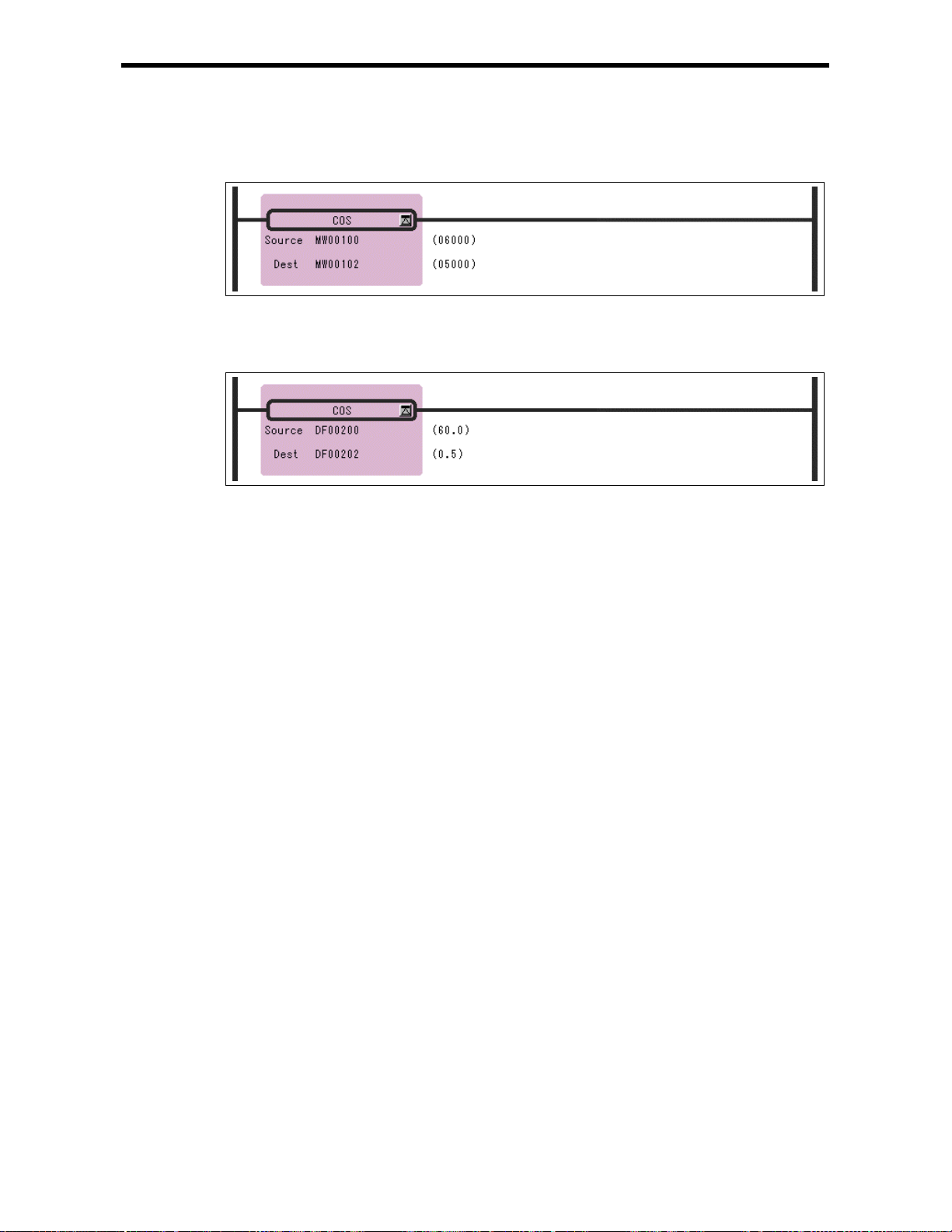
5.3 COSINE Instruction (COS)
[Program Example]
Integer type data
Input X = 60 degrees (MW00100 = 60*100 = 6000)
Output COS (X) = 0.50 (MW00102 = 0.50*10000 = 500)
Real number type data
5-7
Page 90

5.4 TANGENT Instruction (TAN)
[Outline]
The TAN instruction uses the Source as the input (unit = degrees) and stores the tangent of the input in
the Dest. This instruction can be used in a real number operation.
[Format]
Symbol : TAN
Full Name : Tangent
Category : FUNCTION
Icon :
5.4 TANGENT Instruction (TAN)
[Parameter]
Parameter Name Setting
Source
(Input)
Dest
(Output)
· Any real number type register
· Any real number type register with subscript
· Constant
· Any real number type register (except for # and C register)
· Any real number type register with subscript (except for # and C register)
[Program Example]
The tangent of the input valu e (X = 45.0 degrees) [T AN (X) = 1. 0] is calculated.
Notes: TANGENT Instruction cannot be used for integer type and double-length integer type
data.
5-8
Page 91
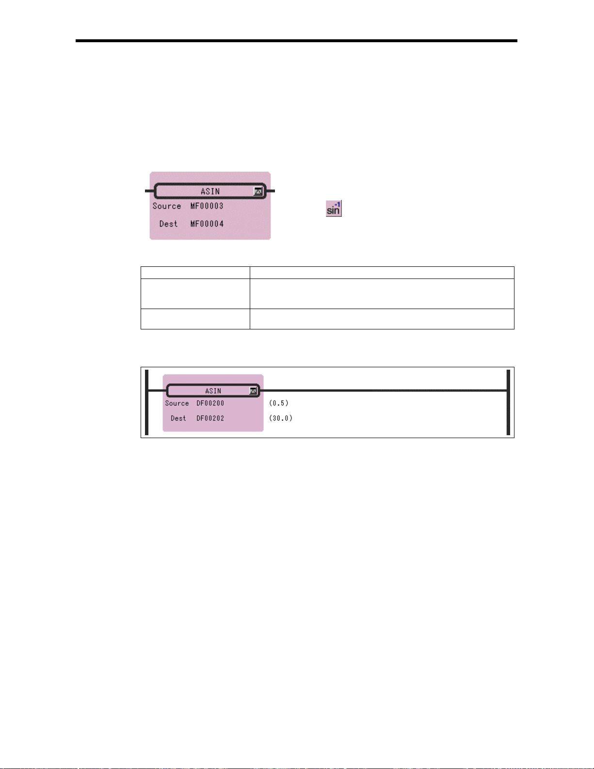
5.5 ARC SINE Instruction (ASIN)
[Outline]
The ASIN inst ructi on uses the Source as the input and stores the arc sine (unit = degrees) of the input
in the Dest. This instruction can be used in a real number operation.
[Format]
Symbol : ASIN
Full Name : Arc Sine
Category : FUNCTION
Icon :
5.5 ARC SINE Inst r uction (ASIN)
[Parameter]
Parameter Name Setting
Source
(Input)
Dest
(Output)
· Any real number type register
· Any real number type register with subscript
· Constant
· Any real number type register (except for # and C register)
· Any real number type register with subscript (except for # and C register)
[Program Example]
The arc sine of the input value (0.5) [ASIN (0.5) = θ = 30.0 degrees] is calculated.
Notes: ARC SINE Instruction cannot be used for in teger t ype and double-length integer type data.
5-9
Page 92

5.6 ARC COSINE Instruction (ACOS)
[Outline]
The ACOS in struction uses the Source as the input and stores the arc cosine (unit = degrees) of the
input in the Dest. This instruction can be used in a real number operation.
[Format]
Symbol : ACOS
Full Name : Arc Cosine
Category : FUNCTION
Icon :
5.6 ARC COSINE Instruction (ACOS)
[Parameter]
Parameter Name Setting
Source
(Input)
Dest
(Output)
· Any real number type register
· Any real number type register with subscript
· Constant
· Any real number type register (except for # and C register)
· Any real number type register with subscript (except for # and C register)
[Program Example]
The arc cosine of the input value (0.5) [ACOS (0.5) = X = 60.0 degrees] is calculated.
Notes: ARC COSINE Instruction cannot be used for integer type and doub le-length integer t ype
data.
5-10
Page 93

5.7 ARC TANGENT Instruction (ATAN)
[Outline]
The ATAN instruction calculates the arc tangent of integer or real number data as the operation result.
The input units and output results for integer and real number data are different. This instruction
cannot be us ed for double-length int eger data.
Integer Type Data
This instruction can be used between -327.68 and 327.67 degrees. The Source is used as the input (1
= 0.01 degrees) and the operation result is stored in the Dest. Upon output, the operation result is
multiplied by 100.
Real Num ber Type Data
The Source is used as the input (unit = degrees) and the arc tangent of the input is stored in the Dest.
This instruction cannot be used for integer type and double-length in teger data.
[Format]
Symbol : ATAN
Full Name : Arc Tangent
Category : FUNCTION
Icon :
5.7 ARC TANGENT Instruction (ATAN)
[Parameter]
Parameter Name Setting
Source
(Input)
Dest
(Output)
· Any integer type and real number type register
· Any integer type and real number type register with subscript
· Subscript register
· Constant
· Any integer type and real number type register (except for # and C
registers)
· Any int eger type an d real number type register w ith subscr ipt (exc ept for #
and C registers)
· Subscript register
5-11
Page 94

5.7 ARC TANGENT Instruction (ATAN)
[Program Example]
Integer type data
Input X = 1.00 (MW00100 = 1.00*100 = 100)
Output X = 45 degrees (MW00102 = 45*100 = 4500)
Real number type data
5-12
Page 95

5.8 EXPONENT Instructio n (EXP)
[Outline]
The EXP instruction uses the Source as the input (x) and stores the natural logarithmic base (e) to the
power of the input (e
number operation.
[Format]
x
) in the Dest as the operation result. This instruction can be used only in a real
Symbol : EXP
Full Name : Exponential
Category : FUNCTION
Icon :
5.8 EXPONENT Instruction (EXP)
[Parameter]
Parameter Name Setting
Source
(Input)
Dest
(Output)
· Any real number type register
· Any real number type register with subscript
· Constant
· Any real number type register (except for # and C register)
· Any real number type register with subscript (except for # and C register)
[Program Example]
e ( = 2.718 3) to the power of the input value (x = 1.0) is calc ulated.
Notes: Maximum value(3.4・・・E + 38) is stored an d an operation error w ill not occur even if the
operation results of EXP instruction in an overflow.
5-13
Page 96

5.9 NATURAL LOGARITHM Instruction (LN)
[Outline]
The LN instruction uses the Source as the input (x) and stores the natural logarithm (Log
input in the Dest as the operation result. This instruction can be used only in a real number operation.
[Format]
Symbol : LN
Full Name : Natural Logarithm
Category : FUNCTION
Icon :
5.9 NATURAL LOG AR I THM Instruct ion (LN)
x
) of the
e
[Parameter]
Parameter Name Setting
Source
(Input)
Dest
(Output)
· Any real number type register
· Any real number type register with subscript
· Constant
· Any real number type register (except for # and C register)
· Any real number type register with subscript (except for # and C register)
[Program Example]
The natural logarithm of the input value (x = 10.0) [Loge(x) = 2.3026] is calculated.
Notes: LN instruction is input(x) value is checked, execute the following handling.
· When the input is minus LN (-1), calculate a absolute value
· When the in pu t is zero LN (0), take -∞ for solution.
5-14
Page 97

5.10 COMMON LOGARITHM Instruction (LOG)
5.10 COMMON LOGARITHM Instruction (LOG)
[Outline]
The LOG instr uc ti on use s the Source as the input (x) and stores the common logarithm (Log
input in the Dest as the operation result. This instruction can be used only in a real number operation.
[Format]
Symbol : LOG
Full Name : Logarithm Base 10
Category : FUNCTION
Icon :
x
10
) of the
[Parameter]
Parameter Name Setting
Source
(Input)
Dest
(Output)
· Any real number type register
· Any real number type register with subscript
· Constant
· Any real number type register (except for # and C register)
· Any real number type register with subscript (except for # and C register)
[Program Example]
The common logarithm of the input value (x = 10.) [ Log10(x) = 1.0] is calculated.
Notes: LOG instruction is input(x) value is checked, execute the following handling.
· When the input is minus LOG (-1), calculate a absolute value
· When the in pu t is zero LOG (0), take -∞ for solution.
5-15
Page 98

6 Data Manipulation Instructions
6 Data Manipulation Instructions
6.1 BIT ROTATION LEFT Instruction (ROTL)
6.2 B I T R O TATION RI GHT Instru c tion ( R OTR)
6.3 MOVE BITS Instruction (MOVB)
6.4 MOVE WORD Instruction (MOVW)
6.5 EXCHANGE Instruction (XCHG)
6.6 SET WORDS Instruction (SETW)
6.7 BYTE-TO-WORD EXPANSION Instruction (BEXTD)
6.8 WORD-TO-WORD COMPRESSION Instruction (BPRESS)
6.9 BINARY SEARCH Instruction (BSRCH)
6.10 SO RT Instruction (SORT)
6.11 BIT SHIFT LEFT Instruction (SHFTL)
6.12 BIT SHIFT RIGHT Instruct io n (SHFT R)
6.13 COPY WORD Instruction (COPYW)
6.14 B YTE SWAP Instruction (BSWAP)
・・・・・・・・・・・・・・・・・・・・・・・・・・・・・・・・・・・・・・・・
・・・・・・・・・・・・・・・・・・・・・・・・・・・・・・・・・・・・・・・
・・・・・・・・・・・・・・・・・・・・・・・・・・・・・・・・・・・・・・
・・・・・・・・・・・・・・・・・・・・・・・・・・・・・・・・・・・・・・・・・・・・
・・・・・・・・・・・・・・・・・・・・・・・・・・・・・・・・
・・・・・・・・・・・・・・・・・・・・・・・・・・・・・・・
・・・・・・・・・・・・・・・・・・・・・・・・・・・・・・・・・・・・・・
・・・・・・・・・・・・・・・・・・・・・
・・・・・・・・・・・・・・・
・・・・・・・・・・・・・・・・・・・・・・・・・・・・・・・・
・・・・・・・・・・・・・・・・・・・・・・・・・・・・・・・・・・
・・・・・・・・・・・・・・・・・・・・・・・・・・・・・・・・
・・・・・・・・・・・・・・・・・・・・・・・・・・・・・・・・・・・
・・・・・・・・・・・・・・・・・・・・・・・・・・・・・・・・・・・・
6-2
6-4
6-6
6-8
6-10
6-12
6-14
6-16
6-18
6-19
6-20
6-21
6-22
6-23
6-1
Page 99

6.1 BIT ROTATION LEFT Instruction (ROTL)
[Outline]
The ROTL instruction is used to rotate bits to the left the number of times designated in the bit table
designat ed by the leading bit a ddress and bit width.
Bit Width (m)
43210m-3m-2m-1
6.1 BIT ROTATION L EFT I nstruction (ROTL)
Head bit address
Number of rotations
[Format]
Symbol : ROTL
Full Name : Bit Rot ate Left
Category : MOVE
Icon :
[Parameter]
Parameter Name Setting
Head Bit Address · Any bit type regis ter (except f or # and C registers)
· Any bit type register with subscript (except for # and C registers)
Number of Rotations · Any integer type register
· Any integer type register with subscript
· Constant
Bit Width · Any integer type register
· Any integer type register with subscript
· Constant
6-2
Page 100
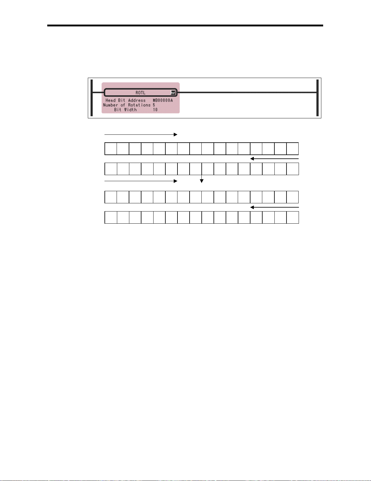
6.1 BIT ROTATION L EFT I nstruction (ROTL)
[Program Example]
The data having MB00000A (bit A of MW00000) as the head address and a bit width of 10 are rotated
five times to th e left .
Rotation symmetry range (Bit width = 10)
C9 4
0
MW00000
Before
execution
F
0 0 1 1 1 0
After
execution
F
C9 4
0 1 0 0 0 0
1 0 0 0
0 1 1 1
MW00001
0
MW00000
MW00001
6-3
 Loading...