

Page 1

LadderWorks
Ladder Editor Operation Manual
Page 2

1 BASIC OPERATION
1 BASIC OPERATION
This section describes the basic operation of the ladder editor.
1.1 CONFIGURATION
1.2 FILE MANAGER
1.2.1 Folder Display
1.2.2 Program File Display
1.3 CREATING NEW PROGRAM
1.3.1 Off-line Mode
1.3.2 On-line Mode
1.4 LADDER EDITOR VIEW
1.4.1 Components of Ladder Editor
1.4.2 Select View
1.5 TOOL BAR
1.5.1 Display Mode
1.5.2 Tool Bar Function
・・・・・・・・・・・・・・・・・・・・・・・・・・・・・・・・・・・・・・・・・・・・・・・・・・・・・・・・・・・・
1.6 KEYBOARD OPERATION
1.6.1 Keyboard Operations on a rung
1.6.2 Shortcut Keys
・・・・・・・・・・・・・・・・・・・・・・・・・・・・・・・・・・・・・・・・・・・・・・・・・・・・・・
・・・・・・・・・・・・・・・・・・・・・・・・・・・・・・・・・・・・・・・・・・・・・・・・・・・・・・・・
・・・・・・・・・・・・・・・・・・・・・・・・・・・・・・・・・・・・・・・・・・・・・・・・・・・・・・・・・・・・・・
・・・・・・・・・・・・・・・・・・・・・・・・・・・・・・・・・・・・・・・・・・・・・・・・・・・・・・・・
・・・・・・・・・・・・・・・・・・・・・・・・・・・・・・・・・・・・・・・・・・・・・
・・・・・・・・・・・・・・・・・・・・・・・・・・・・・・・・・・・・・・・・・・・・・・・・・・・・・・・・・・・・・・
・・・・・・・・・・・・・・・・・・・・・・・・・・・・・・・・・・・・・・・・・・・・・・・・・・・・・・・・・・・・・・
・・・・・・・・・・・・・・・・・・・・・・・・・・・・・・・・・・・・・・・・・・・・・・・・・
・・・・・・・・・・・・・・・・・・・・・・・・・・・・・・・・・・・・・・・・・・・・・・・・・
・・・・・・・・・・・・・・・・・・・・・・・・・・・・・・・・・・・・・・・・・・・・・・・・・・・・・・・・・・・・・・・・
・・・・・・・・・・・・・・・・・・・・・・・・・・・・・・・・・・・・・・・・・・・・・・・・・・・・・・・・・・・・・
・・・・・・・・・・・・・・・・・・・・・・・・・・・・・・・・・・・・・・・・・・・・・・・・・・・・・・・・・・
・・・・・・・・・・・・・・・・・・・・・・・・・・・・・・・・・・・・・・・・・・・・・・・
・・・・・・・・・・・・・・・・・・・・・・・・・・・・・・・・・・・・・・・・・・・・・・
・・・・・・・・・・・・・・・・・・・・・・・・・・・・・・・・・・・・・・・・・・・・・・・・・・・・・・・・・・・・・
1-2
1-3
1-3
1-3
1-5
1-5
1-6
1-8
1-8
1-9
1-13
1-13
1-14
1-15
1-15
1-15
1-1
Page 3

1.1 CONFIGURATION
1.1 CONFIGURATION
When the new ladder editor method is used, the configuration needs to be set.
1. Select View(V) - Configuration(C) of the MotionWorks File Manager menu.
2. “Configuration” dialog box is displayed. Select the Ladder Program tab, and place a check
mark in “Use the new ladder program description”.
3. Click [OK] button. This setting is available after restarting the File Manager.
Notes: If the new ladder program description is selected, all folders created in the original
Ladder editor are not available.
1-2
Page 4

1.2 FILE MANAGER
1.2 FILE MANAGER
The display of the file manager is different in the following respects from the original ladder
program editor to the new ladder editor.
1.2.1 Folder Display
The PLC folder and CPU folder that were made using th e orig inal ladd er editor are shown in the
figure below and cannot be used.
1.2.2 Program File Display
There are the following six kinds of program files displayed in the File Manager.
(1)
(2)
(3)
(4)
(5)
(6)
(1) Not Compiled file that is available in off-line mode.
The program file displays the program without executing the compilation (or
verifying). In the new ladder editor, the program can be saved as a file even if
compiled.
Notes: Refer to 2.9 Verifying Program
1-3
Page 5

1.2 FILE MANAGER
(2) Compiled File.
The program file displays the program already compiled.
(3) Unmatched File
The program file displays the program that has be unmatched in some cases.
There are three cases that cause unmatched.
a. Unmatched version number of data in the controller
b. Unmatched version number of data between the controller and the hard disk on
PC
c. Unmatched CPU environment
When unmatched file is edited, possibility of the restoration of data and how to
restore data are displayed as a message.
(4) Not Compiled and Disabled file that is available at off-line mode.
The program file displays the disabled program without executing the compilation (or
verifying). In a new ladder editor, the program can be saved as a file even if compiled.
(5) Compiled and Disabled File.
The program file displays the disabled program already compiled.
(6) Unmatched and Disabled File
The program file displays the disabled program that is unmatched in some cases.
Notes: It is necessary to adjust all files by loading or dumping CPU environment when
programs are edited connected with the controller at on-line mode.
1-4
Page 6

1.3 CREATING NEW PROGRAM
1.3 CREATING NEW PROGRAM
The programs can be created from every folder such as High Scan Programs at Program folder.
1.3.1 Off-line Mode
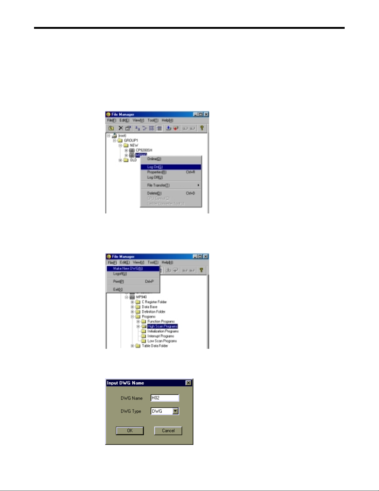
1. Select the folder suitable to the type of program.
2. Select File(F) - Create New DWG(N) from the MotionWorks File Manager menu or from
the popup menu.
3. “Input DWG Name” dialog box is displayed.
Input the program name and select the type of program. Click [OK] button.
4. New program is created. New program is displayed in the File Manager window.
Notes: END instruction is prepared in a new program automatically.
1-5
Page 7
1.3 CREATING NEW PROGRAM
1.3.2 On-line Mode
Make sure to log on the Controller to create programs or definition data for the controller.
1. Select the CPU folder or controller folder to be logged on. Select Log On(G) from File(F)
of the MotionWorks File Manager menu or from the popup menu.
2. Select the folder suitable to the kind of program.
3. Select File(F) - Create New DWG(N) of the MotionWorks File Manager menu or from the
popup menu.
4. “Input DWG Name” dialog box is displayed.
Input the program name and select the type of program. Click [OK] button.
1-6
Page 8
1.3 CREATING NEW PROGRAM
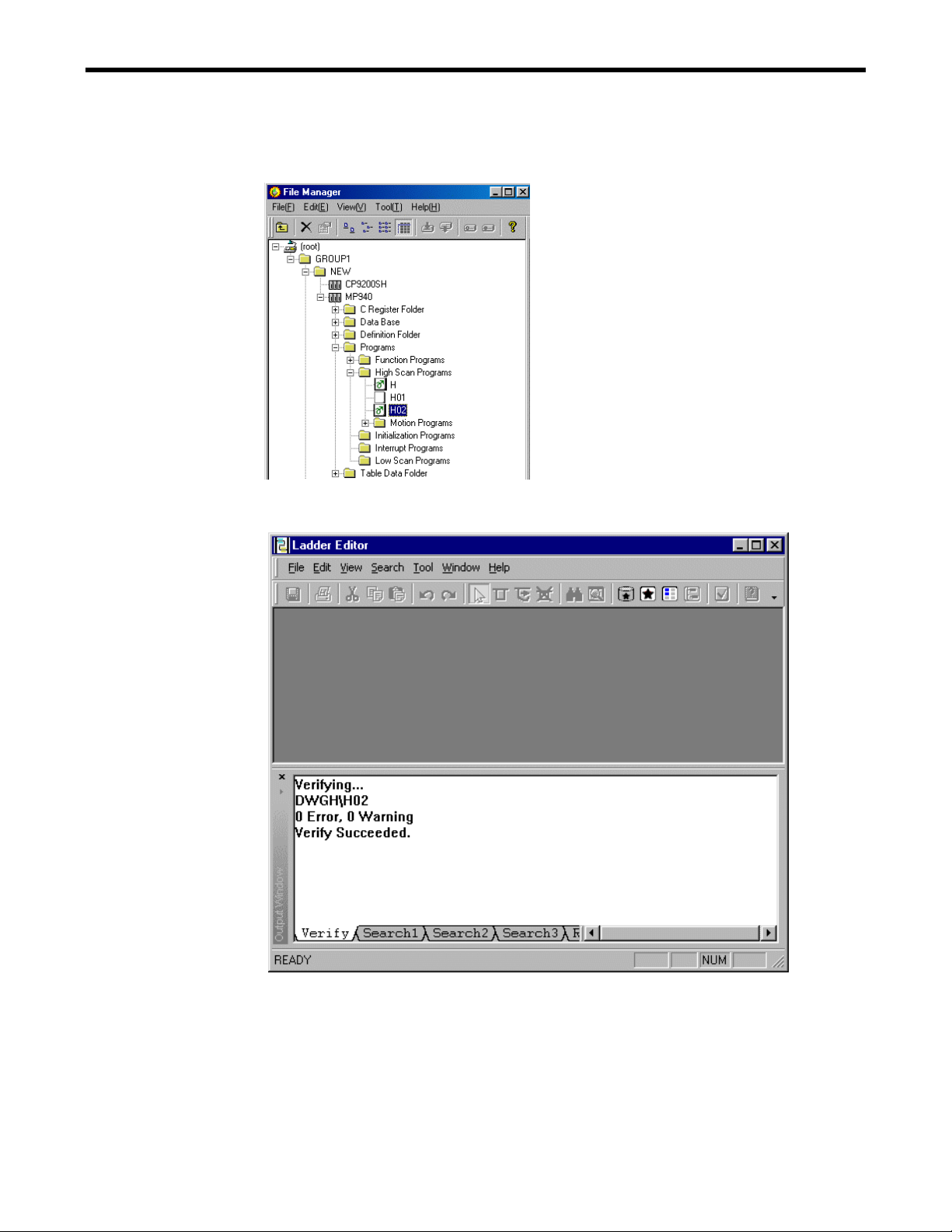
5. The new program is compiled and downloaded to the controller at the same time as it is
created. New program is displayed as a Compiled file in the File Manager window.
6. Then the ladder editor is opened.
1-7
Page 9
1.4 LADDER EDITOR VIEW
1.4.1 Components of Ladder Editor
(1)
(2)
(4)
1.4 LADDER EDITOR VIEW
(5)
(6)
(7)
(3)
Program Window
Output Window
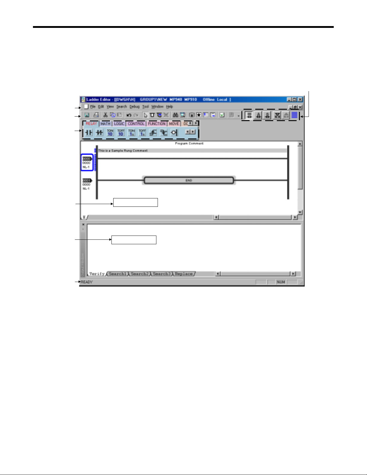
(1) Menu bar
The menu is displayed at the top part of a window.
(2) Tool bar
Each operation of function such as editing function of the menu is displayed with an
icon.
(3) Status bar
A message of the system is displayed.
(4) Instruction palette
Each instruction used to create a program is displayed on the palette as an icon.
(5) Quick view property
Display format is set.
(6) Program window
The program is created on this window. Each program is displayed by the bottom tab.
(7) Output Window
The result of them are displayed when the Verify, Find, and Replace operation is
executed.
1-8
Page 10
1.4 LADDER EDITOR VIEW
1.4.2 Select View
Bottom Tab
Select the tab in the program window, and selected program is displayed.
Multi-Window
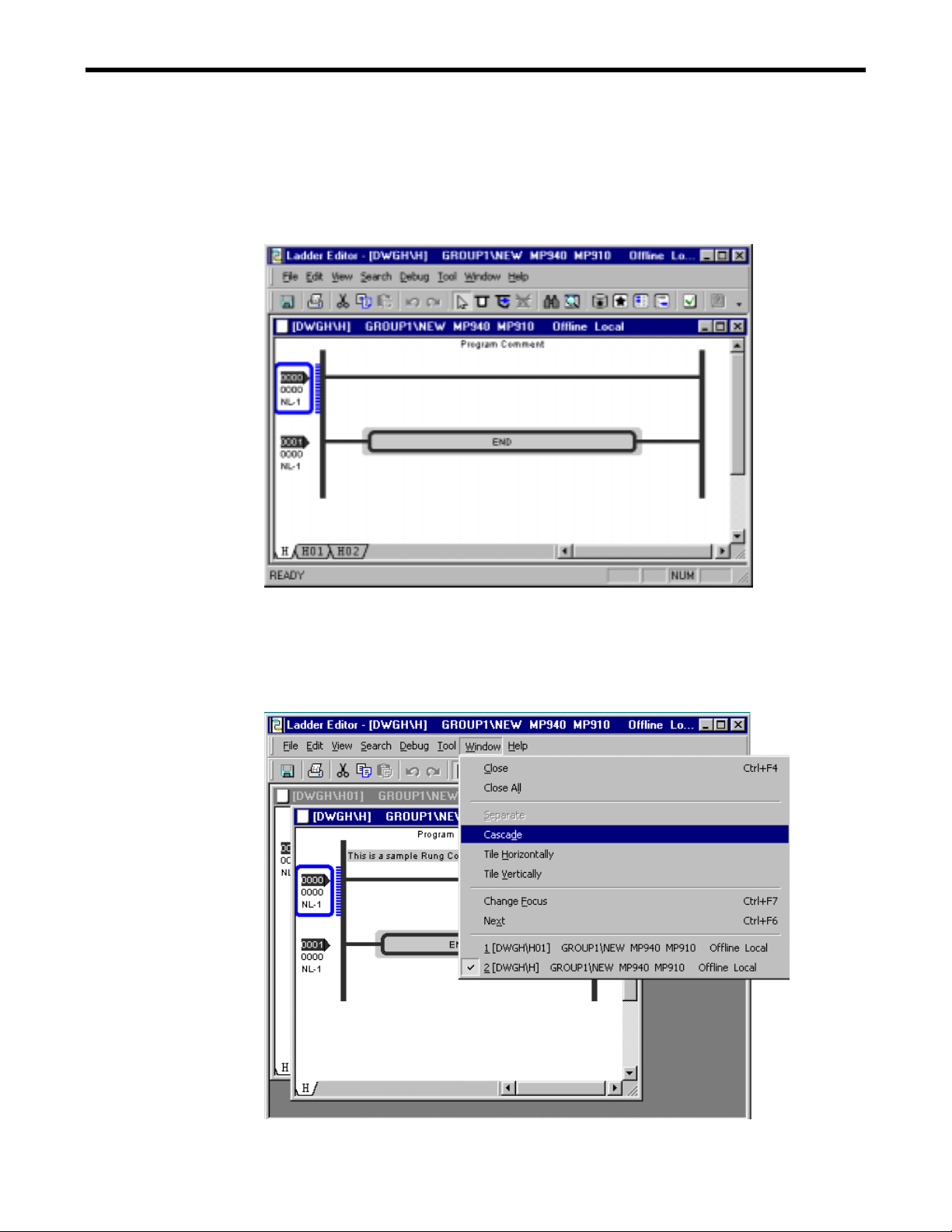
Cascade
Select Window(W) - Cascade(D) to display the currently opened windows of MotionWorks
one over the other.
1-9
Page 11
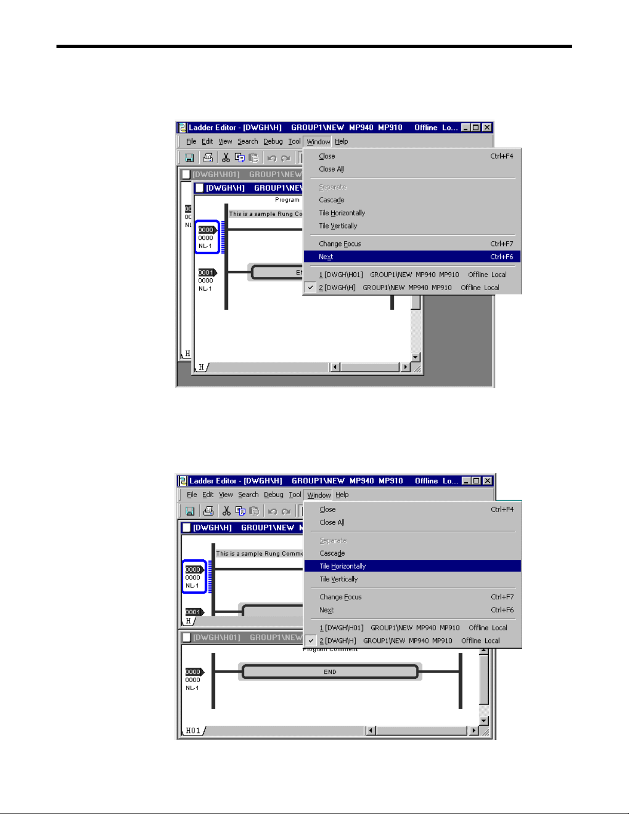
Next
Select Window(W) - Next(X) to change the active program window.
1.4 LADDER EDITOR VIEW
Tile
・Tile Horizontally
Select Window(W) - Tile Horizontally(H) to display the currently opened windows of
MotionWorks one by one horizontally.
1-10
Page 12

1.4 LADDER EDITOR VIEW
・Tile Vertically
Select Window(W) - T ile Vertically(H) to display the currently opened windows of
MotionWorks one by one vertically.
Change Focus
Select Window(W) - Change Focus(F) to change the active window such as program window,
output window in the ladder editor.
Notes: Note: This is different from Next function that changes the active program in the
program window.
1-11
Page 13
1.4 LADDER EDITOR VIEW
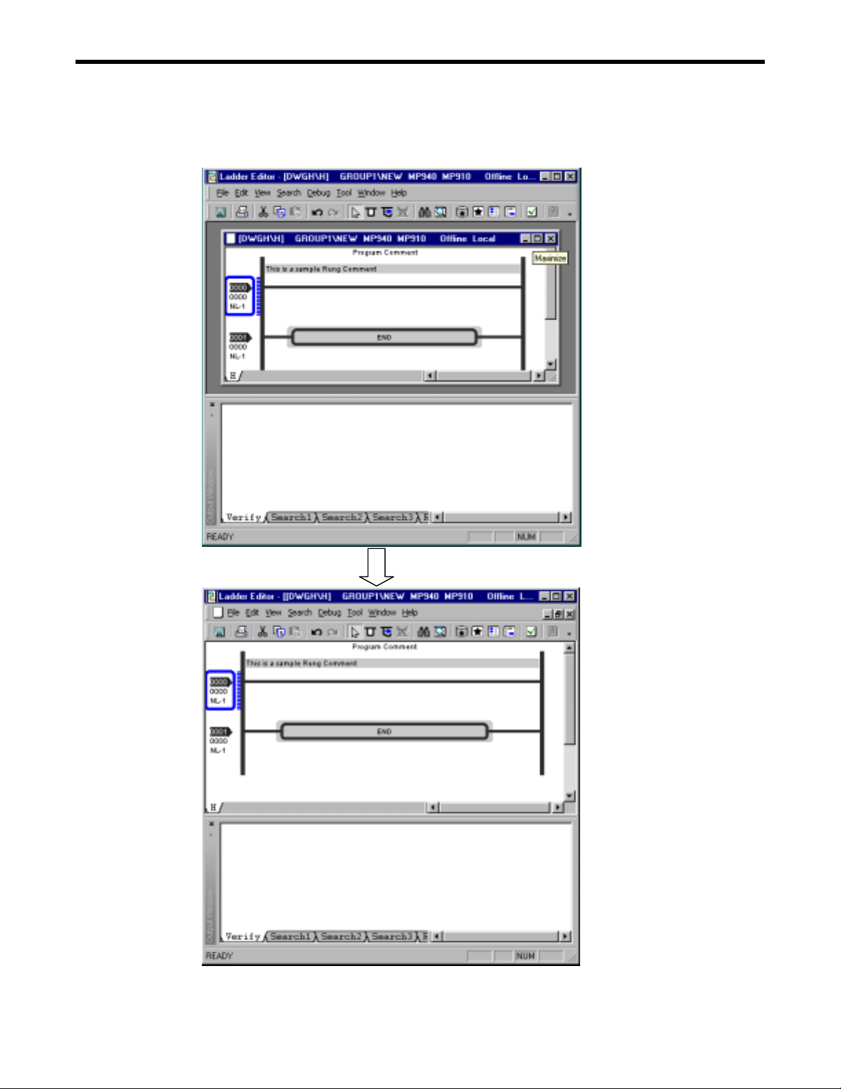
Change the maximum size of program window
Click the button on the title bar to display the maximum size of the program window.
1-12
Page 14

1.5 TOOL BAR
1.5.1 Display Mode
Docked Mode
1.5 Tool Bar
The main menu in the window operation is displayed as an icon on the toolbar.
There are two kinds of display modes for the tool bar.
The toolbar is docked within the frame on the ladder editor.
Undocked Mode
The toolbar is dragged to any place on the window. Its size is adjusted using the arrows
displayed on both sides of the toolbar.
1-13
Page 15

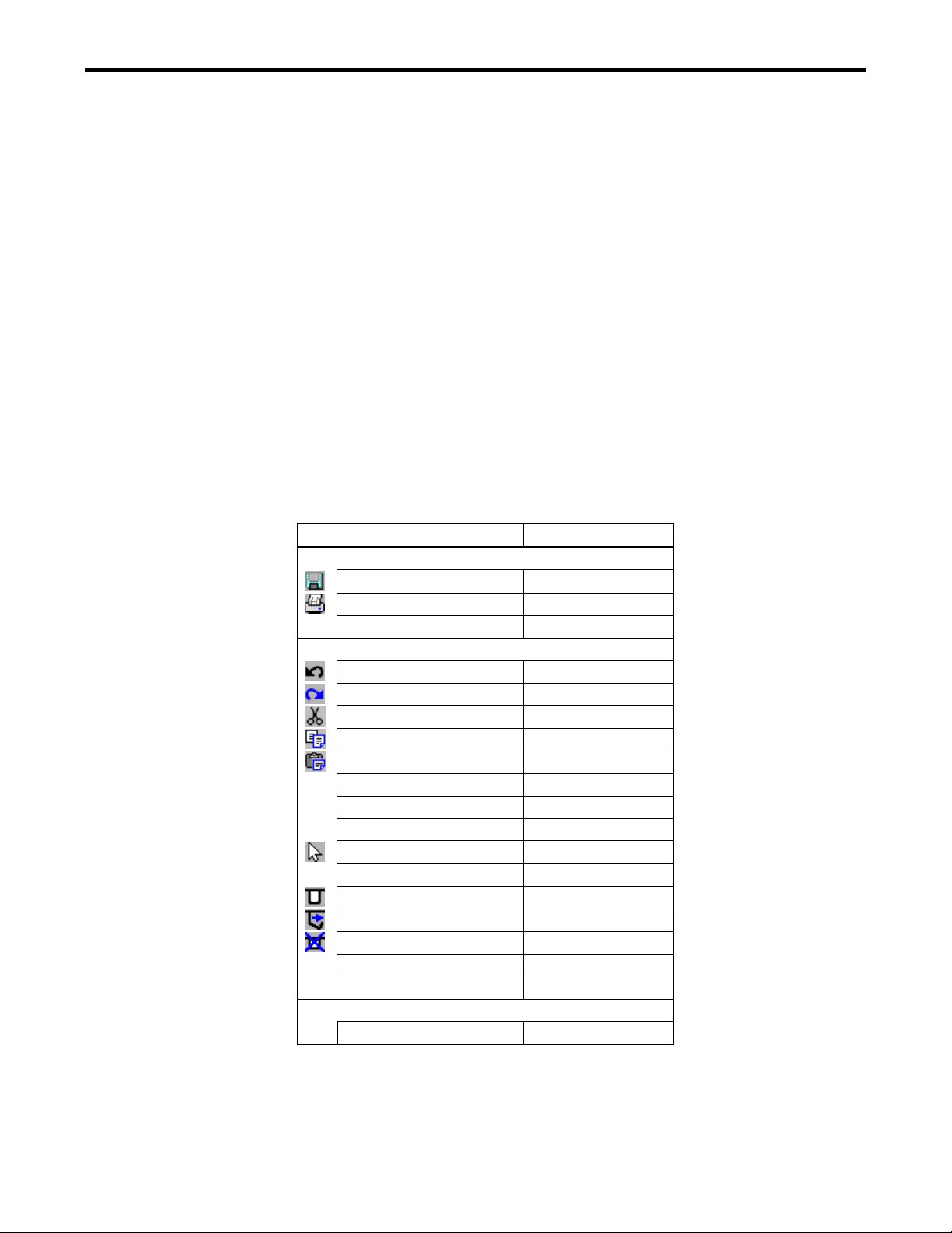
1.5.2 Tool Bar Function
When the mouse is located on the icon of the toolbar, its function is displayed.
Refer to appendix about the details of each function.
Cut
Copy
Save
Paste
1.5 Tool Bar
Nomal E dit Mode
Branch cr ea t e Mo de
Branch Edit Mode
Brach Delete Mode
Symbol Manager
Symbol List
Register Map
Unregistered Symbol List
Print
Redo
Undo
Zoom
Find
Help
Print Manager
Fil e M an age r
Verify
1-14
Page 16
1.6 KEYBOARD OPERATION
Keyboard operations are used to make the ladder programming easier.
1.6.1 Keyboard Operations on a rung
Cursor Operation
Movement in the program comment, the rung, and between rungs is done with the arrow keys.
Jumping to the first program rung is executed by Home key, and jumping to the end rung by End
key. Use Ctrl+Home key to jump to the comment in the first program rung.
1.6.2 Shortcut Keys
The list of the shortcut keys is shown below.
Pull-down Menu
The list of the shortcut keys as well as the pull-down menu items is shown below.
1.6 KEY OPERATION
Pull-down Menu
Menu (Function) Shortcut Key
File (F)
Save (S) Ctrl+S
Print (P) Ctrl+P
Exit (N) Alt+F4
Edit (E)
Undo (U) Ctrl+Z
Redo (R) Ctrl+Y
Cut (T) Ctrl+X
Copy (C) Ctrl+C
Paste (P) Ctrl+V
Delete (D) Delete
Insert (I) Insert
Insert Mode Ctrl+Insert
Normal Edit Mode (N) Ctrl+U
Insert Branch (B) Ctrl+B
Branch Insert Mode (B) Ctrl+I
Branch Edit Mode (E) Ctrl+E
Branch Delete Mode (D) Ctrl+D
Select All (L) Ctrl+A
Verify File (V) F8
View (V)
Editor Options…(E) Alt+Enter
1-15
Page 17

1.6 KEY OPERATION
Pull-down Menu
Menu (Function) Shortcut Key
Search (S)
Find (F) Ctrl+F
Replace (P) Ctrl+H
Goto (G) Ctrl+G
Window (W)
Close (C) Ctrl+F4
Change Focus (F) Ctrl+F7
Next (X) Ctrl+F6
Help (H)
Ladder works Help (H) F1
Pop Hint (P) Shift+F1
Others
Other Operations
Function Shortcut Key
Display the popup menu Shift+F10
Cancel ESC
Menu bar mode control Alt
Enter Enter
Input of null character in text Space
1-16
Page 18

2 PROGRAMMING
2 PROGRAMMING
This section explains how to edit a program.
2.1 PROGRAMMING
2.1.1 Object
2.2 SELECT
2.2.1 Select Object and Display
2.2.2 Cursor Operation
2.2.3 Select Multiple Objects
2.2.4 Range Selection with Mouse
2.3 INSERT
2.3.1 Insert Rung Comment
2.3.2 Insert Rung
2.3.3 Insert Instruction
2.3.4 Insert Branch
2.4 DELETE
2.4.1 Delete Rung Comment
2.4.2 Delete Rung
2.4.3 Delete Instruction
2.4.4 Delete Branch
・・・・・・・・・・・・・・・・・・・・・・・・・・・・・・・・・・・・・・・・・・・・・・・・・・・・・・・・・・・・・・・・・・・・・
・・・・・・・・・・・・・・・・・・・・・・・・・・・・・・・・・・・・・・・・・・・・・・・・・・・・・・・・・・・・・・・
・・・・・・・・・・・・・・・・・・・・・・・・・・・・・・・・・・・・・・・・・・・・・・・・・・・・・・・・・・・・・・・
・・・・・・・・・・・・・・・・・・・・・・・・・・・・・・・・・・・・・・・・・・・・・・・・・・・・・・・・・・・・・・
2.5 BRANCH OPERATION
2.5.1 Branch Operation Mode
2.5.2 Create Branch
2.5.3 Edit Branch
2.5.4 Delete Branch
2.6 EDIT CHARACTER STRING
2.6.1 Edit Character String in the Program Comment
2.6.2 Edit Character String in the Rung Comment
2.6.3 Edit Character String in the Instruction
2.7 EDIT OBJECT
2.7.1 Edit Single Instruction
2.7.2 Edit Operand of Instruction
2.7.3 Edit Multiple Objects
2.7.4 Undo
2.7.5 Redo
・・・・・・・・・・・・・・・・・・・・・・・・・・・・・・・・・・・・・・・・・・・・・・・・・・・・・・・・・・・・・・・・・・・・・
・・・・・・・・・・・・・・・・・・・・・・・・・・・・・・・・・・・・・・・・・・・・・・・・・・・・・・・・・・・・・・・・・・・・・
2.8 SAVE PROGRAM
2.8.1 Save
2.8.2 Save All
・・・・・・・・・・・・・・・・・・・・・・・・・・・・・・・・・・・・・・・・・・・・・・・・・・・・・・・・・・・・・・・・・・・・・
2.9 VERIFY PROGRAM
2.9.1 Verify
2.9.2 Verify All Program
・・・・・・・・・・・・・・・・・・・・・・・・・・・・・・・・・・・・・・・・・・・・・・・・・・・・・・・・・・・・・・・・・・・・
・・・・・・・・・・・・・・・・・・・・・・・・・・・・・・・・・・・・・・・・・・・・・・・・・・・・・・・
・・・・・・・・・・・・・・・・・・・・・・・・・・・・・・・・・・・・・・・・・・・・・・・・・・・・
・・・・・・・・・・・・・・・・・・・・・・・・・・・・・・・・・・・・・・・・・・・・・・・・・・・・・・・・・・・
・・・・・・・・・・・・・・・・・・・・・・・・・・・・・・・・・・・・・・・・・・・・・・・・・・・・・
・・・・・・・・・・・・・・・・・・・・・・・・・・・・・・・・・・・・・・・・・・・・・・・・
・・・・・・・・・・・・・・・・・・・・・・・・・・・・・・・・・・・・・・・・・・・・・・・・・・・・・・
・・・・・・・・・・・・・・・・・・・・・・・・・・・・・・・・・・・・・・・・・・・・・・・・・・・・・・・・・・・・・・・
・・・・・・・・・・・・・・・・・・・・・・・・・・・・・・・・・・・・・・・・・・・・・・・・・・・・・・・・・・・
・・・・・・・・・・・・・・・・・・・・・・・・・・・・・・・・・・・・・・・・・・・・・・・・・・・・・・・・・・・・・・
・・・・・・・・・・・・・・・・・・・・・・・・・・・・・・・・・・・・・・・・・・・・・・・・・・・・・
・・・・・・・・・・・・・・・・・・・・・・・・・・・・・・・・・・・・・・・・・・・・・・・・・・・・・・・・・・・・・・
・・・・・・・・・・・・・・・・・・・・・・・・・・・・・・・・・・・・・・・・・・・・・・・・・・・・・・・・・・
・・・・・・・・・・・・・・・・・・・・・・・・・・・・・・・・・・・・・・・・・・・・・・・・・・・・・・・・・・・・・
・・・・・・・・・・・・・・・・・・・・・・・・・・・・・・・・・・・・・・・・・・・・・・・・・
・・・・・・・・・・・・・・・・・・・・・・・・・・・・・・・・・・・・・・・・・・・・・・・・・・・・
・・・・・・・・・・・・・・・・・・・・・・・・・・・・・・・・・・・・・・・・・・・・・・・・・・・・・・・・・・・・・
・・・・・・・・・・・・・・・・・・・・・・・・・・・・・・・・・・・・・・・・・・・・・・・・・・・・・・・・・・・・・・・
・・・・・・・・・・・・・・・・・・・・・・・・・・・・・・・・・・・・・・・・・・・・・・・・・・・・・・・・・・・・・
・・・・・・・・・・・・・・・・・・・・・・・・・・・・・・・・・・・・・・・・・・・・
・・・・・・・・・・・・・・・・・・・・・・・・・・・・・・・・
・・・・・・・・・・・・・・・・・・・・・・・・・・・・・・・・・・・
・・・・・・・・・・・・・・・・・・・・・・・・・・・・・・・・・・・・・・・・
・・・・・・・・・・・・・・・・・・・・・・・・・・・・・・・・・・・・・・・・・・・・・・・・・・・・・・・・・
・・・・・・・・・・・・・・・・・・・・・・・・・・・・・・・・・・・・・・・・・・・・・・・・・・・・・・
・・・・・・・・・・・・・・・・・・・・・・・・・・・・・・・・・・・・・・・・・・・・・・・・・・
・・・・・・・・・・・・・・・・・・・・・・・・・・・・・・・・・・・・・・・・・・・・・・・・・・・・・・・
・・・・・・・・・・・・・・・・・・・・・・・・・・・・・・・・・・・・・・・・・・・・・・・・・・・・・・
・・・・・・・・・・・・・・・・・・・・・・・・・・・・・・・・・・・・・・・・・・・・・・・・・・・・・・・・・・・・・・・・・・
・・・・・・・・・・・・・・・・・・・・・・・・・・・・・・・・・・・・・・・・・・・・・・・・・・・・
・・・・・・・・・・・・・・・・・・・・・・・・・・・・・・・・・・・・・・・・・・・・・・・・・・・・・・・・・・
2-2
2-2
2-6
2-6
2-9
2-11
2-12
2-13
2-13
2-14
2-15
2-19
2-20
2-20
2-21
2-22
2-23
2-24
2-24
2-24
2-25
2-26
2-27
2-27
2-28
2-29
2-37
2-37
2-42
2-45
2-49
2-49
2-50
2-50
2-50
2-51
2-51
2-53
2-1
Page 19

2.1 PROGRAMMING
2.1 PROGRAMMING
This new ladder editor uses a rung style editing that is difference from the original ladder editor.
The rung is first specified in a program and then the instruction is placed on it. The location of
instruction or the destination of a branch operation is shown so the editing operation such as Cut,
Copy, and Paste is easier to use.
Rules for Rung Style Editing
There are rules to use the rung style editing.
a. Insert a rung connected with the left power rail and the right power rail first.
b. Insert a branch if the parallel circuit is required.
c. Arrange instruction on the rung or the branch.
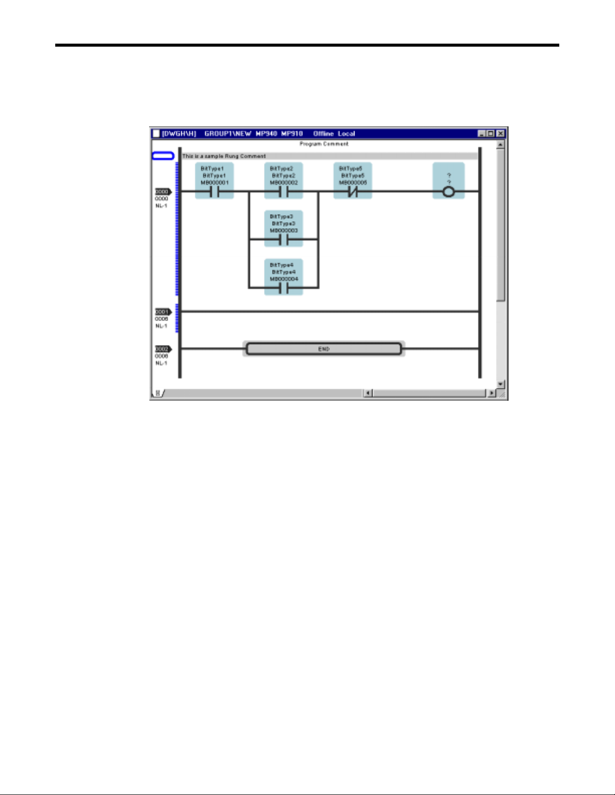
2.1.1 Object
The operation in the ladder program is defined as the object.
Objects In the Program Window
There are different kinds of objects in the program window.
(2)
(1)
(5)
(6)
(7)
(10)
(8)
a.
b.
c.
(9)
(3)
(1) Program Comment
This is a comment for the program, and only one per one program window is
displayed.
The Cut and Delete operation is prohibited.
(2) Branch Block
This is a block that two or more branches are located.
(3) Cursor
The location where the object is arranged is displayed.
(4)
2-2
Page 20

2.1 PROGRAMMING
(4) Rung
This is basic line that instruction and branch are located on.
(5) Rung Comment
This is a comment for a rung. One or more rung comments is available for a rung.
(6) Instruction
This is instruction for the ladder editing. It is classified into another kind.
(7) Branch
This is a branch that shows the parallel circuit.
(8) Rung Left Power Rail
a. Rung Number
The rung number is displayed in order.
b. Step Number
The number of total steps to previous rung is displayed.
c. Nesting Number
The number of nesting is displayed.
Notes: The nesti ng number is increased using I F, FOR, and WHILE instruct i on.
(9) END instruction
This instruction is prepared at creating a program automatically.
The Cut and Delete operation is prohibited.
(10) Edit Mark
This mark Shows the rung edited after the normal termination of verification.
2-3
Page 21
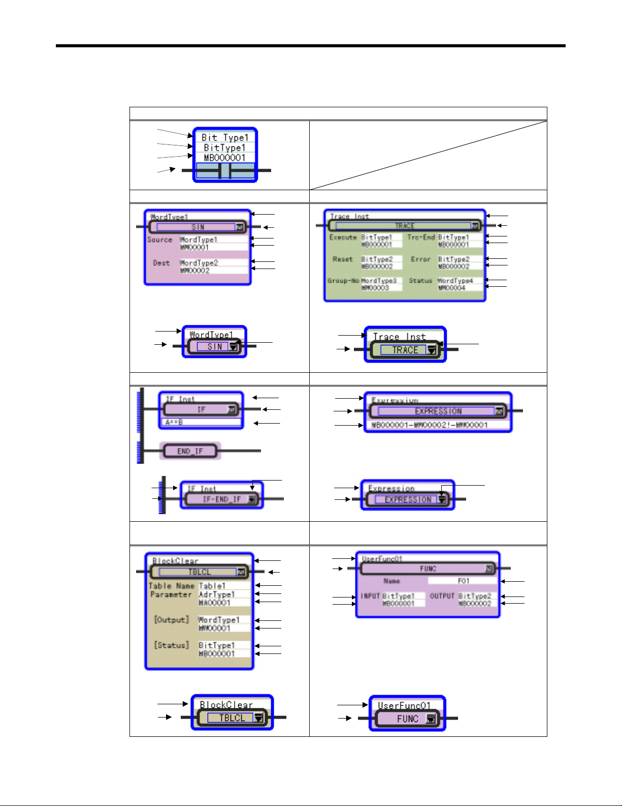
Details of Instructions
Relay Type
(1)
(2)
(3)
(4)
Function Block Type Arithmetic Block Type
(1)
(4)
(2)
(3)
(2)
(3)
Display at Scope OFF
(1)
(4)
Program Control Type IF WHILE Program Control Type EXPRESSION
(5)
Display at Scope OFF
(1)
(4)
2.1 PROGRAMMING
(1)
(4)
(2)
(3)
(2)
(3)
(2)
(3)
(5)
Display at Scope OFF
(1)
u
(4)
Instruction including a text in a operand
[Table Instruction]
Display at Scope OFF
(1)
(4)
(6)
(5)
(1)
(1)
(4)
(7)
Display at Scope OFF
(1)
(4)
(1)
(4)
(8)
(2)
(3)
(2)
(3)
(2)
(3)
(4)
(2)
(3)
Display at Scope OFF
User Function FUNC
(5)
(9)
(2)
(3)
(1)
(4)
(1)
(4)
2-4
Page 22

2.1 PROGRAMMING
(1) Comment for a address or instruction
The comment for a address or instruction is displayed and can be set.
(2) Symbol
The symbol of instruction is displayed and can be set.
(3) Address
The address of register is displayed and can be set.
(4) Instruction Name
The instruction name or instruction diagram is displayed.
(5) Button for Scope
The display format is changed by scope ON and OFF operation
(6) Conditional Expression
The conditional expression is displayed and can be set.
(7) Arithmetic Expression
The arithmetic expression is displayed and can be set.
(8) String
The specified string such as the table name is displayed and can be set.
(9) User Function Name
The user function name is displayed and can be set.
Category of Instruction
The main instruction displayed in the ladder program window is the following eleven
classifications.
RELAY DDC
MATH TABLE
LOGIC SYSTEM
CONTROL SFC
FUNCTION MOTION
MOVE
Notes: Refer to the instruction manual for full details.
2-5
Page 23
2.2 SELECT
2.2 SELECT
There are two kinds of way to select the objects.
a. Click the specified location using the mouse.
b. Select the specified location by moving the cursor in the program with the arrow keys.
Notes: The selected object is highlighted with a specified color line (The default color is
blue).
2.2.1 Select Object and Display
Program Comment
<Selection Method>: Select the display area of a program comment.
<Display>
Rung Comment
< Selection Method >: There are three kinds of selection as follows.
<Display>
Out of the Left Power Rail
Display Area
Comment Input Mode
Rung
< Selection Method >: Select the rung number.
< Display >
2-6
Page 24

2.2 SELECT
Instruction
< Selection Method >: Select the display area of the instruction name of the instruction. The
instruction is highlighted with a blue line when selected.
< Display >
Branch
< Selection Method >: Select the junction of the branch.
< Display >
Case 1 Case 2 Case 3
Branch Block
< Selection Method >: Select the joint of the branch block.
< Display >
Case 1 Case 2 Case 3
2-7
Page 25

2.2 SELECT
Comment
< Selection Method >: Select the display area of the comment of the instruction. The instruction
is highlighted with a blue line when selected.
< Display >
Symbol
< Selection Method >: Select the display area of the symbol of the instruction. The instruction is
highlighted with a blue line when selected.
< Display >
Address
< Selection Method >: Select the display area of the address of the instruction. The instruction is
highlighted with a blue line when selected.
< Display >
Instruction Name
< Selection Method >: Select the display area of the instruction name of the instruction. The
instruction is highlighted with a blue line when selected.
< Display >
2-8
Page 26
2.2.2 Cursor Operation
Example of Down Arrow Key Operation
2.2 SELECT
(2)
(1)
(3)
(4)
(5)
The cursor moves as follows when the down arrow key is selected in this example.
Order Cursor Location
(1) Program comment
(2) Rung comment located out of the left power rail
(3) Rung number 0
(4) Rung number 1
:
(5) Rung number n
Notes: The cursor moves in the opposite direction, if up arrow key is selected.
2-9
Page 27
Example of Right Arrow Key Operation
2.2 SELECT
(2)
(4)
(5)
(3)
(6)
(8)
(7)
(1)
(9)
(10)
(11)
(12)
(13)
(15)
(14)
(16)
The cursor moves as follows when the right arrow key is selected in this example.
Order Cursor Location
(1) Program comment
(2) Rung comment located out of the left power rail
(3) Rung comment
(4) Rung number 0
(5) Insert location on a rung
(6) Instruction
(7) Insert location on a rung
(8) Junction of branch
(9) Branch Block Instruction
(10) Joint of branch
(11) Insert location on a rung
(12) Other instruction
(13) Insert location on a rung
(14) Other instruction
(15) Insert location on a rung
(16) Rung number 1
Notes: Select the down arrow key, if the cursor moves to the under at (8).
2-10
Page 28

2.2 SELECT
2.2.3 Select Multiple Objects
There are three kinds of multiple object selections.
Select Objects in Continuous Range
Select two objects away with the Shift key pushed with the mouse.
The object selected first is the beginning point, and the object selected next is the ending point,
and then all object are selected between them in continuous range.
<Key Operation>: Shift + Arrow Key
Select Objects in Non-Continuous Range
Select two or more objects away with the Ctrl key pushed with the mouse.
The specified objects in non-continuous range are selected.
<Key Operation>: Ctrl + Arrow Key (decided by Enter Key)
Select All Object
All objects except the program comment and END instruction are selected.
<Key Operation>: Ctrl + A or Select Edit (E) - Select ALL (L)
2-11
Page 29

2.2 SELECT
2.2.4 Range Selection with Mouse
Multiple consecutive objects can be selected by enclosing the objects with mouse's drug.
Move the mouse with the mouse button pushed from the starting point within the range of the
selection, a dotted line rectangle which shows the range of the selection is displayed, and the
selected objects are changed into blue. The rectangle disappears when the mouse button is
released in the terminal within the range of the selection, and the selection operation ends.
Single object selection
Multiple objects selection
2-12
Page 30

2.3 INSERT
2.3 INSERT
The Insertion of the rung comment, rung, instruction, and branch is explained.
2.3.1 Insert Rung Comment
1. Select the rung number where the rung comment is newly inserted, and select Edit (E) -
Insert Rung Comment (U) of the menu or from the pop menu.
< Key Operation >: Shift+Insert
2. A new rung comment is displayed at a specified position.
2-13
Page 31

2.3.2 Insert Rung
1. Select the rung position newly inserted and select Edit (E) - Insert Rung (I) of the menu or
from the pop menu.
< Key Operation >: Insert key at a specified position.
2.3 INSERT
2. A new rung is displayed at a specified position.
2-14
Page 32

2.3 INSERT
2.3.3 Insert Instruction
There are four kinds of instruction selection as follows.
a. Select the icon on the instruction palette and insert it to program
b. Drag and drop the icon on the instruction palette and insert it to program
c. Select Mnemonic Operation by shortcut command
d. Select the menu or the pop-up menu
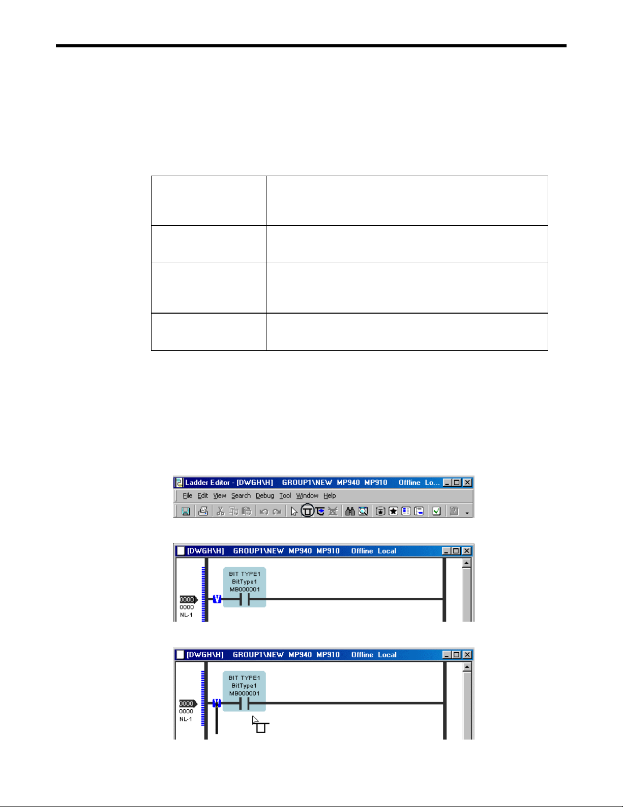
Select the icon on the instruction palette
1. Click the instruction inserted on the instruction palette.
2. The selected instruction icon is displayed in the active status.
3. When the mouse pointer is brought close on the rung in the program, the guide mark ("V")
for insertion is displayed at the position where the instruction can be arranged.
2-15
Page 33

2.3 INSERT
4. The selected instruction is inserted when clicking at the guide mark.
5. The same instru ctio n can be inse rted con tin uousl y durin g th e icon on the inst ruction pale tte is in
the active status.
6. The icon on the instruction palette in the active status i s turned off by clicking the icon
again, or right-click in the program window.
< Key Operation >: Esc
2-16
Page 34

2.3 INSERT
Drag and drop the icon on the instruction palette
1. Click the instruction inserted on the instruction palette.
2. When it is dragged as it is on the rung in the program, the guide mark ("V") for insertion is
displayed at the position where the instruction can be arranged. The cursor is displayed in
the dragging.
3. The instruction inserted on the rung is displayed.
Notes: The insertion operation b y Drag & Drop is only once. The icon on the instruction
palette is in the non-active status.
2-17
Page 35

2.3 INSERT
Select mnemonic operation by shortcut command
1. Click somewhere on the rung and the operation mode is changed into insert mode.
2. Input the mnemonic that is called as shortcut command from the keyboard, and enter it.
3. The input instruction is displayed.
Notes: Refer to the operation manual about the mnemonic.
Select the menu or the pop-up menu
The instruction can be inserted from menu or pop-up menu.
Please refer to 2.7.1 "Edit Single Instruction" for details.
2-18
Page 36

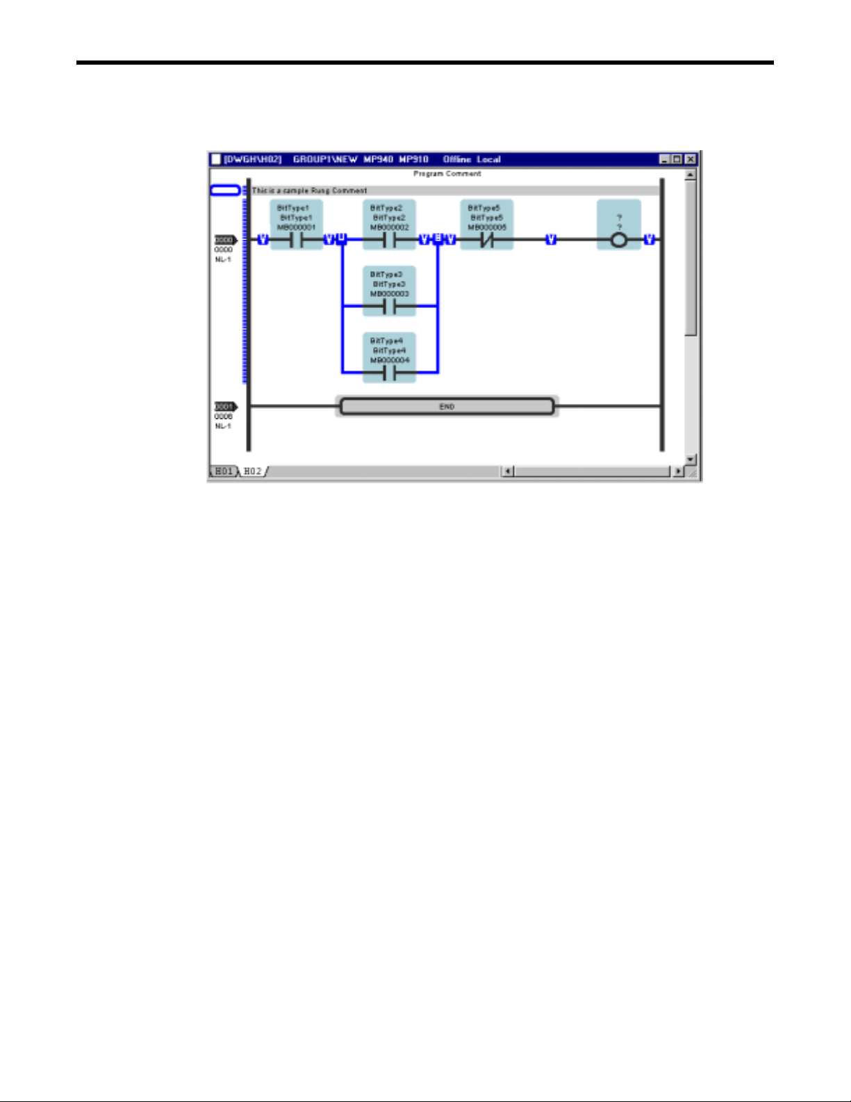
2.3.4 Insert Branch
1. Select Edit (E ) - Branch Insert Mode (B) of the menu or Click the Branch Insert Mode
button on the toolbar.
< Key Operation >: Ctrl + I
2.3 INSERT
2. When the mouse pointer is brought close on the rung in the program, the guide mark ("V"
mark) for insertion is displayed at the position where the branch can be inserted on the rung
and the cursor is changed into the branch insert mode.
3. Select the guide mark ("V" mark) as the beginning point and move the cursor to the right
direction on the rung. The guide mark ("V" mark) is displayed at the position as the ending
point.
4. Click the guide mark and complete to insert the branch on the rung.
5. Click the following insertion beginning position when the branch is continuously inserted.
It is possible to insert branch continuously during the insert mode is selected.
6. It is possible to turn off the branch insert mode by clicking the icon on the toolbar or by
right-click on the branch.
< Key Operation >: Esc
2-19
Page 37

2.4 DELETE
2.4 DELETE
The deletion of the rung comment, the rung, the instruction, and the branch is explained.
2.4.1 Delete Rung Comment
1. Select the deleted rung comment, and select Edit (E) - Delete (D) of the menu or from the
pop menu.
< Key Operation >: Delete
2. The selected rung is deleted.
2-20
Page 38

2.4.2 Delete Rung
1. Select the deleted rung number and select Edit (E) - Delete (D) of the menu or from the
pop menu.
< Key Operation >: Delete
2.4 DELETE
2. The selected rung is deleted and the cursor is moved to next rung.
Notes: The r ung for the END instruction cannot be d eleted.
2-21
Page 39

2.4 DELETE
2.4.3 Delete Instruction
1. Select the instruction name of the deleted instruction, and select Edit (E) - Delete (D ) of
the menu or from the pop-up menu.
< Key Operation >: Delete
2. The instruction is deleted and the object on the right side becomes selected. If there is no
instruction on the rung, the cursor is displayed there.
2-22
Page 40

2.4 DELETE
2.4.4 Delete Branch
1. Select the junction of the deleted branch and select Edit (E) - Delete (D) of the menu or
from the pop-up menu.
< Key Operation >: Delete
2. The selected branch is deleted.
2-23
Page 41
2.5 BRANCH OPERATION
2.5 BRANCH OPERATION
2.5.1 Branch Operation Mode
Change the edit mode from a normal edit mode to the branch operation modes. There are four
kinds of the edit mode as follows.
Normal Edit Mode It is the default mode.
The insert, delete, and edit of the instruction in the program are
available.
<Key Operation >: Ctrl + U from other modes
Branch Create Mode It is the mode to create a branch in the program.
The new branch is created for the selected guide mark position.
<Key Operation >: Ctrl + I from other modes
Branch Edit Mode It is the mode to edit a branch in the program.
The junction or the joint of the selected branch is changed to
the other position.
<Key Operation >: Ctrl + E from other modes
Branch Delete Mode
(Supported in the
future)
It is the mode to delete a branch in the program.
All instructions on the branch are deleted together.
<Key Operation >: Ctrl + D from other modes
2.5.2 Create Branch
The creating a new branch by shortcut key operation is explained. Please refer to 2.3.4 Insert
Branch about the mouse operation.
1. Input the Ctrl + I from the keyboard. The branch insert mode icon on the toolbar becomes
active.
Notes: The branch insert mode mouse pointer is displayed.
2. Move the cursor to the beginning point of branch on the rung and press the Enter key.
3. The end point of the branch is then selected.
2-24
Page 42

4. Move the cursor to the end point of the branch.
2.5 BRANCH OPERATION
5. The new branch is displayed when the Enter key is pressed.
Notes: Normal edit mode is selected by the Ctrl + U.
2.5.3 Edit Branch
Changing the branch by shortcut key operation is explained. The junction or the joint of the
selected branch is changed to the other position.
1. Input the Ctrl + E from the keyboard. The branch edit mode icon on the toolbar becomes
active .
Notes: The branch edit mode mouse pointer is displayed.
2. Move the cursor to the changed point on the branch, and press the Enter key. It can be
changed to other point.
2-25
Page 43

2.5 BRANCH OPERATION
3. Move the cursor to the new point on the rung. The branch is displayed in the light color
while the cursor is moving.
4. Decide the new point by pressing the Enter key.
Notes: Normal edit mode is selected by the Ctrl + U.
2.5.4 Delete Branch
Deleting a branch is explained. Please refer to 2.4.3 Delete Branch about the mouse operation.
1. Select the branch to be deleted with the mouse. The branch is changed into the selection
mode.
Notes: The toolbar and the shortcut key operation are not prepared now.
2. Input the Delete key from the keyboard.
3. The selected branch is deleted.
2-26
Page 44

2.6 EDIT CHARACTER STRING
2.6 EDIT CHARACTER STRING
Editing of a character string in the program window is explained.
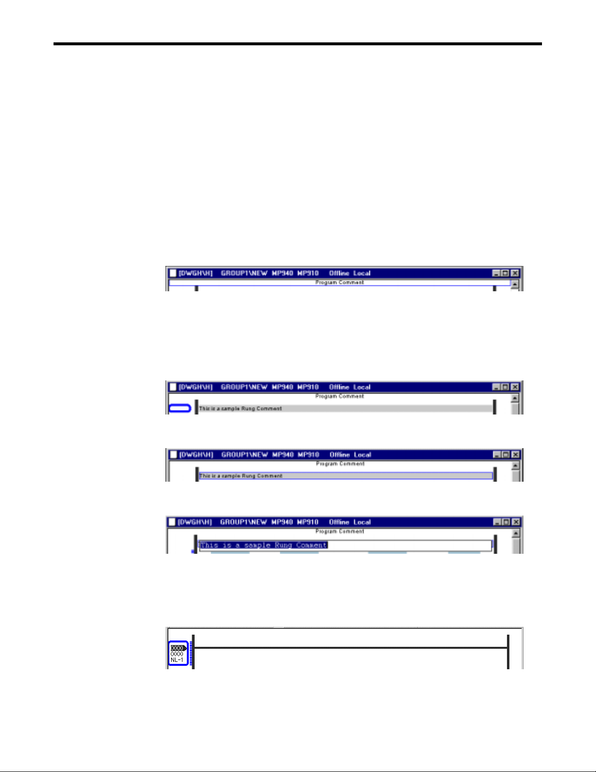
2.6.1 Edit Character String in the Program Comment
1. Select the program comment at the top area of the program window and select Edit (E) -
Edit Program Comment (G) of the menu or from the pop-up menu.
2. The program comment area is displayed in the edit mode. Input the new program comment
character string and press the Enter key.
3. The new program comment is displayed.
Notes: Changing lines in the edit mode is possible by Ctrl + Enter.
2-27
Page 45

2.6 EDIT CHARACTER STRING
2.6.2 Edit Character String in the Rung Comment
1. Select a rung comment in the program window and select Edit (E) - Edit Rung Comment
(E) of the menu or from the pop-up menu.
<Key Operation>: F2
2. The rung comment is displayed in the edit mode. Input the character string for the rung
comment and press the Enter key.
3. The new rung comment is displayed.
Notes: Changing lines in the edit mode is possible by Ctrl + Enter.
2-28
Page 46

2.6 EDIT CHARACTER STRING
2.6.3 Edit Character String in the Instruction
Edit Character String of Comment
1. Select the comment and select Edit (E) - Edit Comment (O) of the menu or from the pop-
up menu, or double-click the comment in the instruction.
2. The selected comment is changed into the edit mode and it is possible to be edited.
Relay Type
Menu Edit Mode
Block Type
Block Type
Program Control Type
Arithmetic Type
Function Type
2-29
Page 47

2.6 EDIT CHARACTER STRING
Edit Character String of Address
1. Select the address and select Edit (E) - Edit Address (E) of the menu or from the pop-up
menu, or double-click the address in the instruction.
<Key Operation>: F2
2. The selected address is changed into the edit mode and it is possible to be edited.
Notes: When immediate data is input to the address, the same data is input to the symbol.
2-30
Page 48

Edit Character String of Symbol
1. Select the symbol and Edit (E) - Edit Symbol (S) of the menu or from the pop-up menu, or
double-click the symbol in the instruction.
<Key Operation>: F2
2.6 EDIT CHARACTER STRING
2. The selected symbol is changed into the edit mode and it is possible to be edited.
Notes: It is necessary to register the symbol for new registration of the instruction. Please
refer to 3.Symbol System.
When immediate data is input to the symbol, the same data is input to the address.
2-31
Page 49

2.6 EDIT CHARACTER STRING
Edit Character String of Instruction Name
1. Select the instruction name and select Edit (E) - Edit Instruction (N) of the menu or from
the pop-up menu, or double-click the instruction name in the instruction.
<Key Operation>: F2
2. The selected instruction name is changed in to the edit mode an d it is possible to be e dited.
Input the instruction name by mnemonic key.
2-32
Page 50

2.6 EDIT CHARACTER STRING
Edit Peculiar Character String of Object
In the operand of the instruction, there is something that contains the character string such as
TABLE instruction besides the symbol, the address, and the comment.
1. Select the peculiar character string and select Edit (E) - Edit String (E) of the menu or
from the pop-up menu, or double-click the peculiar character string in the instruction.
<Key Operation>: F2
2. The selected character string is changed into the edit mode, and it is possible to be edited.
2-33
Page 51

2.6 EDIT CHARACTER STRING
Edit Character String of User Function Name
FUNC that is the user function instruction has the user function name as data.
1. Select the user function name and select Edit (E) - Edit U ser Function (E) of the menu or
from the pop-up menu, or double-click the user function name in the instruction.
<Key Operation>: F2
2. The selected user function name is changed into the edit mode, and it is possible to be
edited.
2-34
Page 52

2.6 EDIT CHARACTER STRING
Edit Character String of Conditional Expression
As for IF and the WHILE instruction, the operand contains the conditional expression.
1. Select the operational expression and select Edit (E) - Edit Conditional Expression (E) of
the menu or from the pop-up menu, or double-click the conditional expression in the
instruction.
<Key Operation>: F2
2. The conditional expression by which the result of a Boolean type is output can be described
only by one line.
2-35
Page 53

2.6 EDIT CHARACTER STRING
Edit Character String of Operational Expression
As for the EXPRESSION instruction, the operand contains the operational expression.
1. Select the EXPRESSION instruction and select Edit (E) - Edit Operational (E) of the
menu or from the pop-up menu, or double-click the operational expression in the
instruction or double-click the operational expression in the instruction.
<Key Operation>: F2
2. The description by C language becomes possible.
Notes: Changing line in the arithmetic expression area is possible by Ctrl + Enter.
2-36
Page 54

2.7 EDIT OBJECT
2.7 EDIT OBJECT
2.7.1 Edit Single Instruction
Insert Instruction
1. Select the guide mark on the rung and select Edit (E) - Insert (I) of the menu or from the
pop-up menu by the right-click.
<Key Operation>: Insert
From the pop-up menu of instruction,
From the pop-up menu between objects,
2. The selected instruction is inserted.
2-37
Page 55

2.7 EDIT OBJECT
Delete Instruction
1. Select the deleted instruction and select Edit (E) - Delete (D) of the menu or from the pop-
up menu by the right-click.
<Key Operation>: Delete
2. The selected instruction is deleted.
Cut Instruction
1. Select the cut out instruction and select Edit (E) - Cut (T) of the menu or from the pop-up
menu by the right-click.
<Key Operation>: Ctrl+X
2. The selected instruction is cut out and its information is saved in the clipboard.
2-38
Page 56

2.7 EDIT OBJECT
Copy Instruction
1. Select the cut out instruction and select Edit (E) - Copy (C) of the menu or from the pop-up
menu by the right-click.
< Key Operation >: Ctrl+C
2. The selected instruction is copied and its information is saved in the clipboard.
Paste Instruction
1. Select the pasted position as the guide mark and select Edit (E) - Paste (P) of the menu or
from the pop-up menu by the right-click.
< Key Operation >: Ctrl+V
2. The instruction saved in the clipboard is pasted on the selected position.
2-39
Page 57

2.7 EDIT OBJECT
Move Instruction by Drag & Drop Operation
1. Click the instruction name of the instruction to be moved and drag it by holding down the
left mouse button. The movement cursor is displayed.
2. Release the mouse button at a target position where the guide mark is displayed. The
dragged instruction is displayed there.
2-40
Page 58

2.7 EDIT OBJECT
Copy Instruction by Drag & Drop Operation
1. Click the instruction name of the instruction to be copied and drag it by holding down the
left mouse button. The movement cursor is displayed.
2. Release the mouse button while pushing the Ctrl key at a target position where the guide
mark is displayed. The copy mode cursor is displayed.
3. The dragged instruction is displayed there.
Notes:
1. The other objects such as branch, branch block, rung, and rung comment can be
similarly edited.
2. As for pasting the rung and the rung comment, it is possible only in the area
outside the left power rail.
2-41
Page 59

2.7 EDIT OBJECT
2.7.2 Edit Operand of Instruction
Delete Symbol or Address of Instruction
1. Select the deleted symbol or address of instruction and select Edit (E) - Delete (D) of the
menu or from the pop-up menu.
< Key Operation > Delete
2. The selected symbol or address is deleted.
2-42
Page 60

2.7 EDIT OBJECT
Cut /Paste Symbol or Address
1. Select the cut out symbol or address of instruction and select Edit (E) - Cut (T) of the
menu or from the pop-up menu.
< Key Operation >: Ctrl+X
2. Select the pasted position as the guide mark and select Edit (E) - Paste (P) of the menu or
from the pop-up menu by the right-click.
< Key Operation >: Ctrl+V
3. The result of Cut/Paste operation is displayed.
2-43
Page 61

2.7 EDIT OBJECT
Copy /Paste Symbol or Address
1. Select the cut out symbol or address of instruction and select Edit (E) - Copy (C) of the
menu or from the pop-up menu.
< Key Operation >: Ctrl+C
2. Select the pasted position as the guide mark and select Edit (E) - Paste (P) of the menu or
from the pop-up menu by the right-click.
< Key Operation >: Ctrl+V
3. The symbol and address of instruction saved in the clipboard is pasted on the selected
position.
2-44
Page 62

2.7 EDIT OBJECT
2.7.3 Edit Multiple Objects
Select Multiple Objects
Selecting Objects in a Continuous Range
1. Select the beginning point in the continuous range.
2. Select the end point with the mouse and push the Shift key.
< Key Operation >: Shift+Right/Left Arrow Key
3. All objects are selected between them in continuous range.
Notes: This operation is available in a whole rung or within the same rung or the same
branch .
2-45
Page 63

2.7 EDIT OBJECT
Selecting Objects in Non-Continuous Range
1. Select the beginning point in the non-continuous range.
2. Select the ending point with the mouse and press the Ctrl key.
< Key Operation >: Ctrl+Arrow Key
3. All objects are selected between them in non-continuous range.
2-46
Page 64

2.7 EDIT OBJECT
Cut/Paste Multiple Objects
Multiple objects can be cut out and pasted to the another position.
1. Select the multiple objects and select Edit (E) - Cut (T) of the menu or from the pop-up
menu by the right-click.
< Key Operation >: Ctrl+X
2. The selected multiple objects are cut out and its information is saved in the clipboard.
3. Select the pasted position as the guide mark and select Edit (E) - Paste (P) of the menu or
from the pop-up menu by the right-click.
< Key Operation >: Ctrl+V
4. The result of Cut/Paste operation is displayed.
2-47
Page 65

2.7 EDIT OBJECT
Copy/Paste Multiple Objects
Multiple objects can be copied and pasted to the another position.
1. Select the multiple objects and select Edit (E) - Copy (C) of the menu or from the pop-up
menu.
< Key Operation >: Ctrl+C
2. The selected multiple objects are copied and saved in the clipboard.
3. Select the pasted position as the guide mark and select Edit (E) - Paste (P) of the menu or
from the pop-up menu by the right-click.
< Key Operation > Ctrl+V
2-48
Page 66

2.7 EDIT OBJECT
4. The result of Copy/Paste operation is displayed.
2.7.4 Undo
The edit process can be returned by the undo operation. Select Edit (E) - Undo (U) of the menu
or from the pop-up menu by the right-click.
< Key Operation >: Ctrl+Z
2.7.5 Redo
The edit process can be operated again after undo operation. Select Edit (E) - Redo (R) of the
menu or from the pop-up menu by the right-click.
< Key Operation >: Ctrl+Y
2-49
Page 67

2.8 SAVE PROGRAM
2.8 SAVE PROGRAM
There are two methods of saving the program, Save and Save All. The program is saved in
both the hard disk on PC and the controller in on-line mode, but it is saved in only the hard disk
on PC in the off-line mode.
2.8.1 Save
An active program file is overwrote and saved.
1. Select File (F) - Save (S) of the menu.
< Key Operation >: Ctrl+S
2. An active program file is overwrote and saved.
2.8.2 Save All
All opened program files are overwrote and saved.
1. Select File (F) - Save All (L) of the menu.
2. All opened program files are overwrote and saved.
2-50
Page 68

2.9 VERIFY PROGRAM
2.9 VERIFY PROGRAM
The program is compiled.
2.9.1 Verify
An active program file is compiled.
1. Select Edit (E) - Verify File (V) of the menu.
< Key Operation >: F8
2. An active program file is verified. The result of the compile, warnings, and error messages
are displayed in the output window.
3. The edit mark in the program disappears when verify is being executed.
→→→→
2-51
Page 69

2.9 VERIFY PROGRAM
4. The display on the tree of the file manager is changed from “Not Compiled File” to
“Compiled File” for the file from which verify was executed.
→→→→
Error Display Format
When verify is executed, one example of the content of the display of the output window is
shown below.
DWGH¥H ( Rung 0, Step 1, Operand 0, Address): error C1041 : The operand is not available.
(1) (2) (3) (4) (5) (6)
(1) Program Name
The program name where error occurs is displayed.
(2) Rung Number
The rung number where error occurs is displayed.
(3) Step Number
The step number where error occurs is displayed.
When the instruction does not exist on the rung, 0 is displayed.
(4) Operand Information
The number and the type such as the symbol and the address, etc. of operand
information are displayed.
(5) Error Code
The code of each error type to the error is displayed.
(6) Detailed Information
The error detailed content and method of the solution are displayed.
2-52
Page 70

2.9 VERIFY PROGRAM
2.9.2 Verify All Program
All program files for the selected controller are verified.
1. Select Edit (E) - Verify All Program Files (F) of the menu.
2. All program files for the selected controller are verified. The result of the compile,
warnings, and error messages are displayed in the output window.
3. The edit mark in the program disappears when verify is being executed.
4. The display on the tree of the file manager is changed from “Not Compiled File” to
“Compiled File” for the file from which verify was executed.
Notes: Edit (E) - Verify (F) , Edit (E) - Verify All Program Files (F) operation is available
from the File Manager window as well as the Ladder Editor window.
2-53
Page 71

3 DISPLAY
3 DISPLAY
3.1 EDITOR OPTION DIALOG
3.1.1 Editor Option Dialog Configuration
3.1.2 Color
3.1.3 Font
3.1.4 Ladder Display
3.1.5 Control
3.1.6 Key
3.2 ZOOM
・・・・・・・・・・・・・・・・・・・・・・・・・・・・・・・・・・・・・・・・・・・・・・・・・・・・・・・・・・・・・・・・・・・・・・
・・・・・・・・・・・・・・・・・・・・・・・・・・・・・・・・・・・・・・・・・・・・・・・・・・・・・・・・・・・・・・・・・・・・・・
・・・・・・・・・・・・・・・・・・・・・・・・・・・・・・・・・・・・・・・・・・・・・・・・・・・・・・・・・・・・・
・・・・・・・・・・・・・・・・・・・・・・・・・・・・・・・・・・・・・・・・・・・・・・・・・・・・・・・・・・・・・・・・・・・・
・・・・・・・・・・・・・・・・・・・・・・・・・・・・・・・・・・・・・・・・・・・・・・・・・・・・・・・・・・・・・・・・・・・・・・・
・・・・・・・・・・・・・・・・・・・・・・・・・・・・・・・・・・・・・・・・・・・・・・・・・・・・・・・・・・・・・・・・・
3.3 INSTRUCTION PALETTE
3.3.1 Instruction Palette
3.3.2 User Customized Tab
3.3.3 Quick View Property
3.4 OUTPUT WINDOW
・・・・・・・・・・・・・・・・・・・・・・・・・・・・・・・・・・・・・・・・・・・・・・・・・・・・
3.5 TOOLBAR CUSTOMIZE DIALOG
3.5.1 Toolbar customize Dialog Configuration
3.5.2 Commands
3.5.3 Toolbars
3.5.4 Keyboard
3.5.5 Other
3.5.6 Edit Icon Image
3.5.7 Customizing Operation
3.6 FUNCTION KEYS
3.6.1 Function Bar
3.6.2 Function Key Assignment
・・・・・・・・・・・・・・・・・・・・・・・・・・・・・・・・・・・・・・・・・・・・・・・・・・・・・・・・・・・・・・・
・・・・・・・・・・・・・・・・・・・・・・・・・・・・・・・・・・・・・・・・・・・・・・・・・・・・・・・・・・・・・・・・・・
・・・・・・・・・・・・・・・・・・・・・・・・・・・・・・・・・・・・・・・・・・・・・・・・・・・・・・・・・・・・・・・・・
・・・・・・・・・・・・・・・・・・・・・・・・・・・・・・・・・・・・・・・・・・・・・・・・・・・・・・・・・・・・・・・・・・・・
・・・・・・・・・・・・・・・・・・・・・・・・・・・・・・・・・・・・・・・・・・・・・・・・・・・・・・・・・・・・
・・・・・・・・・・・・・・・・・・・・・・・・・・・・・・・・・・・・・・・・・・・・・・・・・・・・・・
・・・・・・・・・・・・・・・・・・・・・・・・・・・・・・・・・・・・・・・・・・・・・・・・・・・・・・・・・・・・・・
・・・・・・・・・・・・・・・・・・・・・・・・・・・・・・・・・・・・・・・・・・・・・・・
・・・・・・・・・・・・・・・・・・・・・・・・・・・・・・・・・・・・・・・・・・・・
・・・・・・・・・・・・・・・・・・・・・・・・・・・・・・・・・・・・・・・・・・・・・・・
・・・・・・・・・・・・・・・・・・・・・・・・・・・・・・・・・・・・・・・・・・・・・・・・・・・・・・・・・
・・・・・・・・・・・・・・・・・・・・・・・・・・・・・・・・・・・・・・・・・・・・・・・・・・・・・・
・・・・・・・・・・・・・・・・・・・・・・・・・・・・・・・・・・・・・・・・・・・・・・・・・・・・・・・
・・・・・・・・・・・・・・・・・・・・・・・・・・・・・・・・・・・・・・・・
・・・・・・・・・・・・・・・・・・・・・・・・・・・・・・・・・・・・・・・
・・・・・・・・・・・・・・・・・・・・・・・・・・・・・・・・・・・・・・・・・・・・・・・・・・・・・
・・・・・・・・・・・・・・・・・・・・・・・・・・・・・・・・・・・・・・・・・・・・・・・・・・・
3-2
3-2
3-2
3-4
3-5
3-7
3-8
3-9
3-10
3-10
3-11
3-14
3-16
3-18
3-18
3-18
3-19
3-20
3-21
3-22
3-25
3-26
3-26
3-26
3-1
Page 72

3.1 EDITOR OPTION DIALOG
3.1 EDITOR OPTION DIALOG
Editor Option Dialog Display
The dialog box where the options of the ladder editor window are displayed.
1. Select View (V) - Editor Options… (E).
2. The editor option dialog is displayed.
3.1.1 Editor Option Dialog Configuration
< Key Operation >: Alt+Enter
Tab Explanation
Color Set the color of the background, text, and lines in the ladder editor.
Font Set the font property in the program window.
Ladder Set the ladder display property in the program window.
Control Set the max. number of open windows in the output window.
Key Set the instruction names with a mnemonic key.
3.1.2 Color
(1)
(2)
(3)
(4)
(5)
(6)
(7)
3-2
Page 73

3.1 EDITOR OPTION DIALOG
(1) Setting Item
Select the item from the drop down list displayed with the menu button of the combo
box.
(2) Category
This is available when “instruction” is selected. Click the menu button, and the
category of instruction is displayed.
Color:
The color of the background, text, line is set.
Click the menu button and the color set box is displayed.
3-3
Page 74

3.1 EDITOR OPTION DIALOG
(3) Background
The background color is set.
(4) Text
The text color is set.
(5) Line
The line color is set.
(6) Sample
The selections of a set item, the category, and the color, etc. are preview displayed.
(7) Default
All settings in the color tab are returned to the default settings.
3.1.3 Font
The font displayed in the program window is set.
(1)
(4)
(2)
(3)
(5)
(1) Font Type
The selected font in the combo box list is displayed.
(2) Attributes
B : The bold-faced type is set or unset.
I : The italic character type is set or unset.
U
: The underline of the character is set or unset.
(3) Size
The font size is set.
(4) Sample
The preview of the selected character is displayed.
(5) Default
All settings in the font tab are returned to the default settings.
3-4
Page 75

3.1.4 Ladder Display
A detailed display item in the program window is set.
3.1 EDITOR OPTION DIALOG
(1)
(2)
(10)
(11)
(3)
(4)
(5)
(12)
(13)
(14)
(15)
(6)
(16)
(17)
(7)
(8)
(18)
(19)
(9)
(20)
(21)
Program Comment
(1) Program Comment
Display/Hide of the program comment is set by the check box.
(2) Max Lines
Unlimited: There is no limitation
Limited (1-5): There is the limitation of the display number of lines of the program
comment.
(3) Alignment
The display positions in the program comment are set in either the left justification,
the center or the right justification.
Rung Comment
(4) Rung Comment
Display/Hide of the rung comment is set by the check box.
(5) Max Lines
Unlimited: There is no limitation
Limited (1-5): There is the limitation of the display number of lines of the rung
comment.
(6) Alignment
The display positions in the rung comment are set in either the left justification, the
center or the right justification.
Rung
(7) Rung Wrap
The rung turn control is available or not available is set by the check box.
3-5
Page 76

3.1 EDITOR OPTION DIALOG
(8) Number of New Rungs
The number of rung when new program is created is set.
(9) Number of Inserted Rungs
The number of rung when it is inserted is set.
Address
(10) Address
Display/Hide of the address of the instruction is set by the check box.
(11) Max Characters of Line
The maximum of characters a line is fixed by 14 now.
Symbol
(12) Symbol
Display/Hide of the symbol of the instruction is set by the check box.
(13) Max Characters of Line 10-20
The maximum number of characters on a line is set between 10 and 20.
(14) Max Line
The maximum number of lines is set between 1 and 5 or set to no limit.
(15) Word Wrap
The character string return function is set or not set by the check box.
Comment
(16) Comment
Display/Hide of the comment of the instruction is set by the check box.
(17) Max Characters of Line
The maximum number of characters on a line is set between 10 and 20.
(18) Max Line
The maximum number of lines is set between 1 and 5.
(19) Alignment
The display positions in the comment of the instruction are set in either the left
justification, the center or the right justification.
(20) Default
All settings in the ladder tab are returned to the default settings.
(21) Others
The Expression and detailed program comment is set.
(22)
(23)
(24)
Expression
3-6
Page 77
3.1 EDITOR OPTION DIALOG
(22) Max Characters of Line (1-512)
The maximum number of characters on a line is set between 1 and 512.
(23) Word Wrap
The character string return function at more than the maximum number of characters
displayed is set or not set by the check box. When not set, the characters over the
maximum of characters are not displayed.
Program Comment
(24) New Program Default Comment
Character string as program comment is set, when new program is opened. "Program
Comment" is displayed as the default.
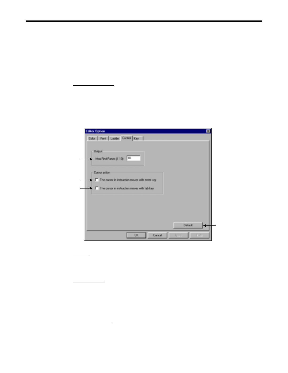
3.1.5 Control
(1)
(2)
(3)
(4)
Output
(1) Find Windows (1-10)
The number of windows displayed in the output window is set. The default number is
three.
Cursor action
(2) Cursor in the Instruction moves with Enter key.
The cursor in the instruction moves with Enter key when the cursor is in the
instruction.
(3) Cursor in the Instruction moves with Tab key.
The cursor in the instruction moves with Tab key when the cursor is in the instruction.
Default button (4)
All settings in the control tab are returned to the default settings.
3-7
Page 78

3.1.6 Key
The allocation of shortcut commands for each instruction is displayed.
3.1 EDITOR OPTION DIALOG
(1)
(2)
(3)
(4)
(5)
(1) Key
Each shortcut command as mnemonic key is displayed.
(2) Category
The category of instruction is displayed.
(3) Instruction Name
The instruction name is displayed.
(4) Explanation
The explanation for instruction is displayed.
(5) Default
All settings in the key tab are returned to the default settings.
Change the mnemonic key
1. Move the cursor to the key to be changed.
2. Click the key item and it is changed to the edit mode.
3. Change the key and press the Enter key. This change is effective the next time the ladder
editor is started.
< Key Operation > F2
3-8
Page 79

3.2 ZOOM
3.2 ZOOM
The display scaling of the ladder window is set.
1. Select View (V) - Zoom (Z).
2. The zoom dialog box is displayed.
(1)
(2)
Zooming
(1) Scale
Select the button for the prepared scale.
(2) Select
Input the specified scale in the input box.
3-9
Page 80

3.3 INSTRUCTION PALETTE
3.3 INSTRUCTION PALETTE
The instruction palette displays the instruction group for the ladder programming by dividing
each category in the tab. The instruction dragged from the instruction palette is dropped on a
target position in the program. The original tabs can be used or added on the instruction palette
by the user.
3.3.1 Instruction Palette
Display/Hide of the instruction palette can be set with selecting View (V) - Instruction Palette
(I).
Instruction Palette Display
1. Select View (V) - Instruction Palette (I).
2. The instruction palette is displayed.
(1)
(2)
(3) (4)
(5)
(6)
(7)
(8)
(9)
(10) (11)
(1) RELAY
The RELAY category is displayed.
(2) MATH
The MATH category is displayed.
(3) LOGIC
The LOGIC category is displayed.
(4) CONTROL
The CONTROL category is displayed.
(5) FUNCTION
The FUNCTION category is displayed.
(6) MOVE
The MOVE category is displayed.
(7) DDC
The DDC category is displayed.
(8) TABLE
The TABLE category is displayed.
(9) SYSTEM
The SYSTEM category is displayed.
(10) SFC
The SFC category is displayed.
(11) MOTION
The MOTION category is displayed.
3-10
Page 81

3.3 INSTRUCTION PALETTE
Notes: Refer to Appendix 1 for detailed information.
3.3.2 User Customized Tab
The user original tab can be customized on the instruction palette by using instructions on it.
User Customized Tab Display
1. Select Tool (T) - Customize User Tab… (C).
2. The customize user tab is displayed.
Details of Customize User Tab Dialog
(2) (3)
(1)
(4) (5)
(6)
(7)
(8)
(9)
(10)
(11)
(12)
(13)
3-11
Page 82

3.3 INSTRUCTION PALETTE
(1) Available Instruction
All instructions of each category on the instruction palette are displayed.
(2) Tab Title
The name of the edited user tab is displayed.
(3) User Tab Instruction
The instruction registered in the user tab to be edited is displayed.
(4) Add->
The instruction selected from available instruction window is registered in the user
tab.
(5) <-Remove
The specified instruction on the user tab is deleted.
(6) Up
The cursor in the user tab instruction window moves to the upper direction.
(7) Down
The cursor in the user tab instruction window moves to the lower direction.
(8) OK
The Setting is reflected in the instruction palette, and the dialog is closed.
(9) Cancel
The Setting is canceled, and the dialog is closed.
(10) New
The user tab is newly created.
(11) Rename
The edited user tab is renamed.
(12) Delete
The edited user tab is deleted.
(13) Tab Color
The background color for the edited user tab is set.
3-12
Page 83

3.3 INSTRUCTION PALETTE
Set Customized User Tab
1. Select the New button.
Input the user tab name in the dialog.
2. Select the added instruction in the available instruction window.
3. Select the Add button and the selected instruction is registered in the user tab instruction
window.
4. Set the tab color and select the OK button, the specified user tab is added on the instruction
palette.
3-13
Page 84

3.3 INSTRUCTION PALETTE
3.3.3 Quick View Property
The quick view property sets the display form of the operand of the instruction.
Display/Hide of the quick view property can be set with selecting View (V) - Quick View
Property (V).
Quick View Property Display
1. Select View (V) - Quick View Property (V).
2. The quick view property is displayed.
(1)
(2) (3) (4) (5)
(1) Symbol/Comment/Address Display
The address, symbol, and comment of the instruction are all displayed.
(2) Address/Comment Display
The address and comment of the instruction are displayed.
(3) Symbol/Comment Display
The symbol and comment of the instruction are displayed.
(6)
(7) (8)
3-14
Page 85

3.3 INSTRUCTION PALETTE
(4) Decrease the Number of Comment Lines
The number of comment lines displayed is decreased by one line at each click.
⇒
⇒
⇒⇒
(5) Increase the Number of Comment Lines
The number of comment lines displayed is increased by one line at each click.
⇒
⇒
⇒⇒
(6) Number of Comment Lines Display
The present number of comment lines is displayed.
(7) Scope All On
The scope of all the instructions is turned on.
(8) Scope All Off
The scope of all the instructions is turned off.
3-15
Page 86

3.4 OUTPUT WINDOW
3.4 OUTPUT WINDOW
The output window is a window that shows the execution result of Find/Replace/Verify
operation under the program window. The Display/Hide can be set with selecting View (V) -
Output (O) of the menu.
1. Select View (V) - Output (O).
2. The output window is displayed under the program window.
3-16
Page 87
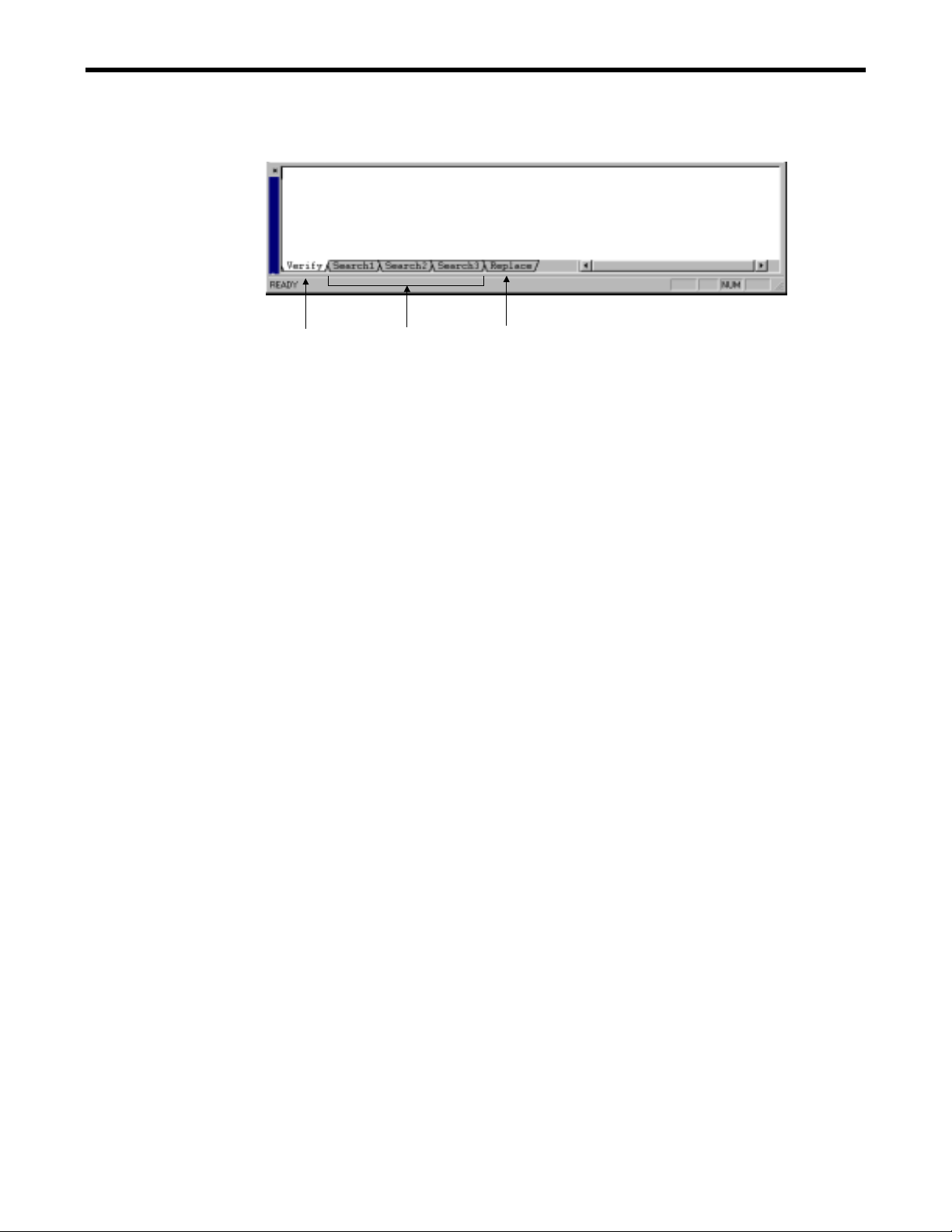
Detail of the Output Window
3.4 OUTPUT WINDOW
(1) (2)
(3)
(1) Verify
The result of the verify execution, the warnings, the error messages are displayed in
the output window.
(2) Find
The result of “Find All” operation is displayed. The number of windows that is
changeable in the editor option dialog is set as the default.
(3) Replace (supported in the future)
The result of “Replace All” operation is displayed.
3-17
Page 88

3.5 TOOLBAR CUSTOMIZE DIALOG
3.5 TOOLBAR CUSTOMIZE DIALOG
Toolbar Customize Dialog Box Display
The dialog box where the customized data of the toolbar is set is displayed.
1. Select View(V) - Toolbar(T) - Customize (C) of the menu or right-click on the toolbar and
select Customize (C).
2. The toolbar customize dialog box is displayed.
3.5.1 Toolbar customize Dialog Configuration
Tab Content
Commands Display the list of commands added to the toolbar.
Toolbars reate a new customized toolbar and rename it.
Keyboard Set the shortcut key for each command.
Others Set the properties of the menu and the toolbar.
3.5.2 Commands
(1)
(2)
(3)
(4)
(1) Categories
Select the category of the command added to the toolbar.
(2) Commands
The command list of the selected category is displayed.
(3) Description
The description of the selected command is displayed.
(4) Close
The toolbar customize dialog box is closed.
3-18
Page 89

3.5 TOOLBAR CUSTOMIZE DIALOG
3.5.3 Toolbars
(2)
(3)
(4)
(5)
(6)
(7)
(1)
(1) Toolbars
Set the check box of the toolbar.
(2) Reset
Reset the selected standard toolbar. All customized data is removed from it. The
button is disabled when the user-defined toolbar is selected.
(3) Reset All
Reset all standard toolbars except the user-defined toolbars.
(4) New
Create a new user-defined toolbar. The toolbar name dialog box is displayed when the
button is selected. Input the toolbar name in the input box.
(5) Rename
Rename the user-defined toolbar.
(6) Delete
Delete the user-defined toolbar.
(7) Show text labels
Set the display/hide the button labels on the toolbar.
Display labels: Hide labels:
3-19
Page 90

3.5.4 Keyboard
3.5 TOOLBAR CUSTOMIZE DIALOG
(10)
(1)
(2)
(9)
(3)
(6)
(7)
(8)
(4)
(5)
(1) Category
Select the category from the drop down list.
(2) Commands
Select the command assigned to the shortcut key.
(3) Current Keys
The current assigned shortcut key of the selected command is displayed.
(4) Press new shortcut key
Input the shortcut key assigned to the selected command in the input box. It is
automatically displayed as “Ctrl+C” when Ctrl+C is input.
(5) Assigned to:
The current command assigned by the shortcut key input in the input box above is
displayed. It is displayed, "Unassigned" when not assigned.
(6) Assign
Assign the new shortcut key in the input box to the selected command.
(7) Remove
Remove the assignment of the shortcut key from the selected command.
(8) Reset All
Reset all assignments of the shortcut keys. The assignments of the shortcut keys
returns to the initial settings.
(9) Description
The function description of the selected command is displayed.
(10) Set Shortcut for:
Supported in the future.
3-20
Page 91

3.5.5 Other
(1)
(2)
(3)
3.5 TOOLBAR CUSTOMIZE DIALOG
(4)
(5)
(6)
(7)
(8)
Toolbar:
(1) Screen tip
Set display/hide of the screen tip on the toolbar.
(2) Display of shortcut key in the screen tip
Set display/hide of the shortcut key in the screen tip. This check box is available when
screen tip is set to display.
(3) Icon type
Set large type for the icons on the toolbar.
Menu:
(4) Menu display type
Set the check box, recently used commands are first displayed in the menu.
(5) Full menu display
Set the check box, all the commands are displayed after a few minutes are passed
when the cursor is put on the open menu. This check box is available when menu
display type is set.
(6) Menu animations
Select the menu animation type to be None, Unfold, Slide, and Fade.
(7) Menu shadows.
Set display/hide of the shadow of the menu.
(8) Reset my usage data
Reset the menu display type changed by recent usage.
3-21
Page 92

3.5 TOOLBAR CUSTOMIZE DIALOG
3.5.6 Edit Icon Image
1. Select View(V) - Toolbar(T) - Customize (C) of the menu or right-click on the toolbar and
select Customize (C).
2. The toolbar customize dialog box is displayed.
3. Right-click on the selected icon on the toolbar.
4. The pop-up menu is displayed.
Edit Operation
(1) Reset to Default
Reset the button image and display form of the selected command.
(2) Copy button image
Copy the button image of the selected command. It can be edited in the edit button
image dialog.
(3) Delete
Delete the selected command on the toolbar.
(4) Button Appearance
Modify the design of the selected button. The button appearance dialog is displayed.
(5) Image
The image of the selected command is displayed.
(6) Text
The text of the selected command is displayed.
(7) Image and Text
The image and text of the selected command are displayed.
(8) Start Group
Insert the separator at the left of the selected command.
3-22
Page 93

3.5 TOOLBAR CUSTOMIZE DIALOG
Button Appearance Dialog
The button image assigned to the button is created and modified.
1. Select View(V) - Toolbar(T) - Customize (C) of the menu or right-click on the toolbar and
select Customize (C).
2. The toolbar customize dialog box is displayed.
3. Right-click on the selected icon on the toolbar.
4. The pop-up menu is displayed.
5. Select Button Appearance of the pop-up menu.
6. The button appearance dialog box is displayed.
(1)
(2)
(4)
(5)
(6)
(3)
(7)
(1) Button display form
Select the display form of the button.
(2) Select button image
Select the used button image.
(3) User-defined image list
The user-defined images are displayed. It is available when the user-defined image is
selected.
(4) New
Create a new button image of the command. The edit button image dialog is displayed.
It is available when the user-defined image is selected.
(5) Edit
Edit the selected button image of the command. The edit button image dialog is
displayed. It is available when the user-defined image is selected.
(6) Description
The function description of the selected command on the toolbar is displayed.
(7) Button text
Modify the caption of the selected button It is available when ‘text only ‘ or ‘image
and text’ is selected in the button display form.
3-23
Page 94
3.5 TOOLBAR CUSTOMIZE DIALOG
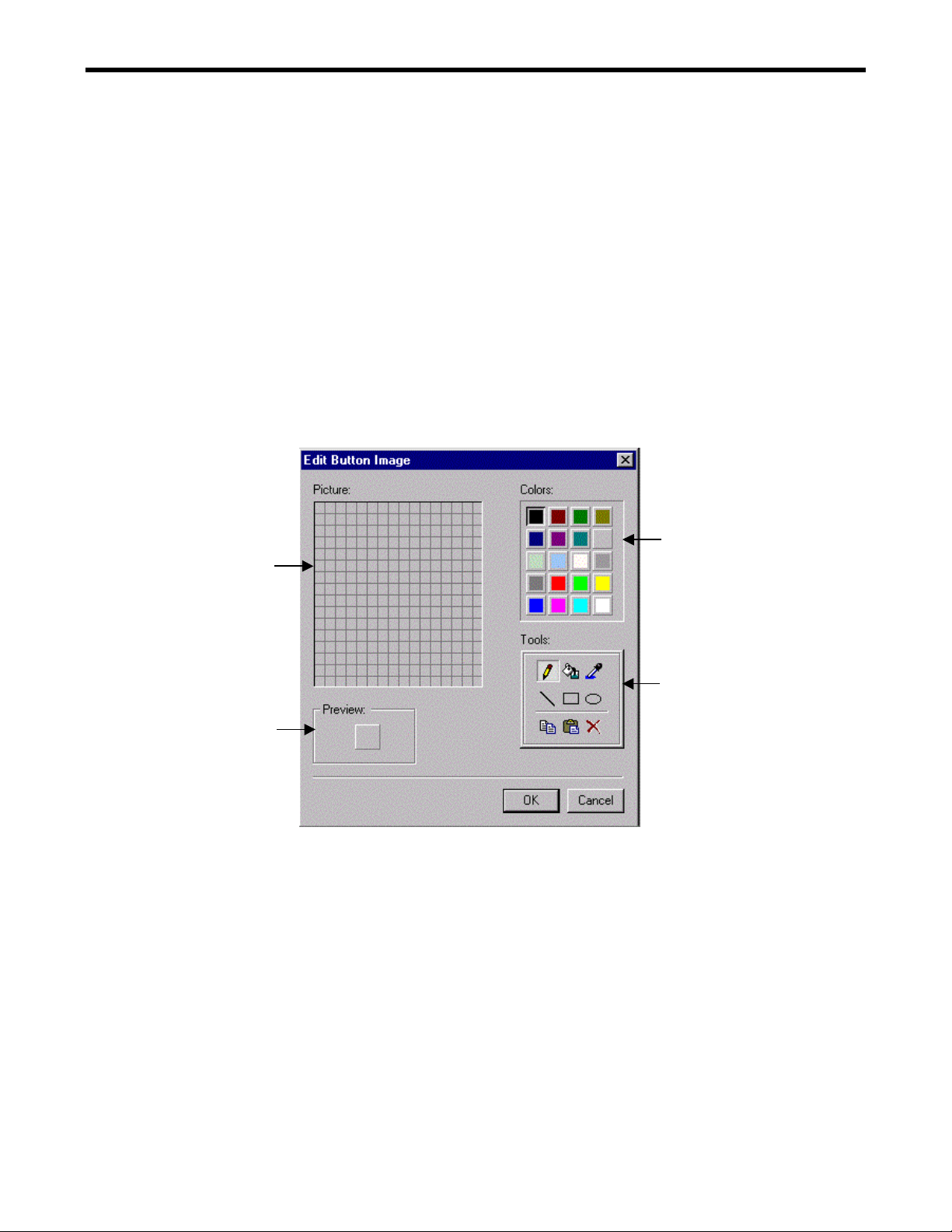
Edit Button Image Dialog
The button image assigned to the button is edited.
1. Select View(V) - Toolbar(T) - Customize (C) of the menu or right-click on the toolbar and
select Customize (C).
2. The toolbar customize dialog box is displayed.
3. Right-click on the selected icon on the toolbar.
4. The pop-up menu is displayed.
5. Select Button Appearance of the pop-up menu.
6. The button appearance dialog box is displayed.
7. Select New(N) or Edit(E) button.
8. The edit button image dialog box is displayed.
(2)
(1)
(3)
(4)
(1) Picture
Set or modify the button image by clicking the pixels of the picture.
(2) Colors
Select the color of the button image.
(3) Tools
Draw the picture using the tools.
(4) Preview
The button image is previewed in actual size.
3-24
Page 95

3.5 TOOLBAR CUSTOMIZE DIALOG
3.5.7 Customizing Operation
Add Command
The customize dialog box is displayed.
1. Select the command tab.
2. Drag the selected icon.
3. Drop it to the selected toolbar.
Delete Command
The customize dialog box is displayed.
1. Drag the selected icon.
2. Drop it outside the toolbar
3-25
Page 96

3.6 FUNCTION KEYS
3.6 FUNCTION KEYS
3.6.1 Function Bar
The function bar is displayed.
1. Select View(V) - Function Bar (U) from the menu.
2. The function bar is displayed.
The function keys are assigned below.
Function key Function name Content
F2 Edit Put the selected object in editing.
F3 Show Key Assign The key assignment in the edit option dialog is displayed. It can
be edited
F8 Verify Verify the program.
They following function keys are only displayed when using the symbol list in the ladder editor.
The following function keys are only available when the symbol list is opened. Refer to "5.4
Operation on the ladder editor" for details.
Function key Function name Content
F5 Find Next Search for the next data.
F9 Sort Sort the selected item.
F11 Program Activate the program window.
F12 Symbol List Activate the symbol list. Open the symbol list when it is not
opened. It can be edited.
3.6.2 Function Key Assignment
The function key assignment is displayed below including the Windows® standard assignment.
It can be changed at the toolbar customize dialog.
F and key Shift+ Ctrl+ Alt+
F1 Help Screen Tip
F2 Edit
F3 Show Key Assign
F4 Close End
F5 Find Next
F6 Next
F7 Switch Focus
F8 Verify
F9 Sort
F10 Pop-up
Menu
F11 Program
F12 Symbol List
Notes: The application like the front end processor occasionally uses the function key.
Be careful not to compete with that application, in changing the assignment of the
function key.
3-26
Page 97

4 FIND/REPLACE
4 FIND/REPLACE
4.1 FIND
4.1.1 Find
4.1.2 Find from Files…
4.2 REPLACE
4.3 CROSS REFERENCE
4.3.1 Display Cross Reference Window
4.3.2 Cross Reference Condition
4.3.3 Output to File
・・・・・・・・・・・・・・・・・・・・・・・・・・・・・・・・・・・・・・・・・・・・・・・・・・・・・・・・・・・・・・・・・・
・・・・・・・・・・・・・・・・・・・・・・・・・・・・・・・・・・・・・・・・・・・・・・・・・・・・・・・・・・・・・・・・・・・・・・
・・・・・・・・・・・・・・・・・・・・・・・・・・・・・・・・・・・・・・・・・・・・・・・・・・・・・・・・・・・
・・・・・・・・・・・・・・・・・・・・・・・・・・・・・・・・・・・・・・・・・・・・・・・・・・・・・・・・・・・・・・
・・・・・・・・・・・・・・・・・・・・・・・・・・・・・・・・・・・・・・・・・・・・・・・・・・
・・・・・・・・・・・・・・・・・・・・・・・・・・・・・・・・・・・・・・・・・・・・
・・・・・・・・・・・・・・・・・・・・・・・・・・・・・・・・・・・・・・・・・・・・・・・・・・
・・・・・・・・・・・・・・・・・・・・・・・・・・・・・・・・・・・・・・・・・・・・・・・・・・・・・・・・・・・・・
4-2
4-2
4-5
4-9
4-13
4-13
4-15
4-17
4-1
Page 98

4.1 FIND
4.1 FIND
The specified character string is found in the ladder program and its location is displayed.
4.1.1 Find
The specified character string is found in the displayed ladder program.
1. Select Search (S) - Find (F) of the menu or from the pop-up menu.
< Key Operation >: Ctrl+F
2. The dialog box is displayed.
Input the found character string and the condition
4-2
Page 99

4.1 FIND
3. Select the Find Next button and a specified character string is found according the
specified condition. The cursor is moved to its position and it is displayed in the reverse
mode when there is a character string that meets it.
All specified character strings are found according the specified condition when the Find
All button is selected. The result of searching is displayed in the output window.
Notes: 3 panes for finding displayed in the output window are prepared as a default. The
default number is changeable in the editor option window. The result of searching is
usually displayed in the Search 1 pane and it is displayed in another pane when
[Output New Pane] is checked
4. Double-click the result of searching in the pane, the cursor is moved to the specified
position in the program and is displayed in the reverse mode.
4-3
Page 100

Details of Find Dialog
(1)
(3)
4.1 FIND
(2)
(4)
(1) Find Word
Input the found character string. The used character strings are displayed in the drop
down list and can be used when inputting it.
(2) Select Word Dialog Display
This is available when Command is selected.
Select the button and the Select Word dialog box is displayed. The specified
instruction is set to the Command input box when clicking the instruction name in it.
The same word is reflected to the Find Word input box in Find dialog box when OK
button is selected.
(5)
4-4
 Loading...