

Page 1
YASKAWA AC Drive-L1000E
AC Drive for Elevator Applications
Quick Start Guide
Type: CIMR-LEA
Models:
To properly use the product, read this manual thoroughly and retain
for easy reference, inspection, and maintenance. Ensure the end user
receives this manual.
200 V Class: 3.7 to 110 kW (5 to 150 HP)
400 V Class: 4.0 to 132 kW (5 to 175 HP)
L
E
DM
O
N
I
TO
R
J
V
R
O
U
P
N
1
8
4
D
S
1
D
S
2
P
W
R
R
U
N
D
S
1
D
S
2
S
R
T
E
A
ADY
T
U
R
S
U
N
A
L
A
R
M
P
(RU
G
O
N)
H
,
B
L
T
B
,
H
B
B
E
F
,
S
E
O
V
,
U
V
OH
,OL
OC
,
G
F
,S
C
PF,O
C
:LIG
,
P
GO
F
H
Ot
A
T
,O
h
e
F
r
B
:
F
B
,
a
O
L
u
F
I
lt
N
C
K
:
LI
G
H
TO
F
F
MANUAL NO. TOEP YAIL1E 01A
Receiving
Mechanical Installation
Electrical Installation
Start-Up Programming &
Operation
Troubleshooting
Periodic Inspection &
Maintenance
Option Card Installation
Specifications
Parameter Table
Standards Compliance
1
2
3
4
5
6
7
A
B
C
Page 2

Copyright © 2014 YASKAWA ELECTRIC CORPORATION.
All rights reserved. No part of this publication may be reproduced, stored in a retrieval system, or transmitted,
in any form, or by any means, mechanical, electronic, photocopying, recording, or otherwise, without the prior
written permission of Yaskawa. No patent liability is assumed with respect to the use of the information
contained herein. Moreover, because Yaskawa is constantly striving to improve its high-quality products, the
information contained in this manual is subject to change without notice. Every precaution has been taken in
the preparation of this manual. Nevertheless, Yaskawa assumes no responsibility for errors or omissions.
Neither is any liability assumed for damages resulting from the use of the information contained in this
publication.
2 YAS KA WA TOEPYAIL1E01A YASKAWA AC Drive L1000E Quick Start Guide
Page 3

◆ Quick Reference
Drive a Synchronous PM Motor
L1000E can operate synchronous PM motors. Refer to Flowchart C: Auto-Tuning for PM Motors
on page 66.
Perform Auto-Tuning
Automatic tuning sets motor parameters. Refer to Types of Auto-Tuning on page 68.
Maintenance Check Using Drive Monitors
Use drive monitors to check fans, capacitors, and other components may require maintenance. Refer to Performance Life Monitors Maintenance
Monitors on page 144.
Fault Display and Troubleshooting
Refer to Troubleshooting on page 130.
Refer to UL Standards on page 219.
Standards Compliance
YAS KA WA TOEPYAIL1E01A YASKAWA AC Drive L1000E Quick Start Guide 3
Page 4

4 YAS KA WA TOEPYAIL1E01A YASKAWA AC Drive L1000E Quick Start Guide
Page 5

Table of Contents
Quick Reference . . . . . . . . . . . . . . . . . . . . . . . . . . . . . . . . . . . . . . . . . . . . . . . . . . . . . . .3
i. Preface & General Safety ................................................................................................. 7
Preface . . . . . . . . . . . . . . . . . . . . . . . . . . . . . . . . . . . . . . . . . . . . . . . . . . . . . . . . . . . . . .7
General Safety. . . . . . . . . . . . . . . . . . . . . . . . . . . . . . . . . . . . . . . . . . . . . . . . . . . . . . . . .7
1. Receiving ......................................................................................................................... 15
Model Number and Nameplate Check . . . . . . . . . . . . . . . . . . . . . . . . . . . . . . . . . . . . .15
2. Mechanical Installation................................................................................................... 17
Mechanical Installation . . . . . . . . . . . . . . . . . . . . . . . . . . . . . . . . . . . . . . . . . . . . . . . . .17
3. Electrical Installation ...................................................................................................... 23
Standard Connection Diagram . . . . . . . . . . . . . . . . . . . . . . . . . . . . . . . . . . . . . . . . . . .23
Main Circuit Connection Diagram . . . . . . . . . . . . . . . . . . . . . . . . . . . . . . . . . . . . . . . . .26
Terminal Cover . . . . . . . . . . . . . . . . . . . . . . . . . . . . . . . . . . . . . . . . . . . . . . . . . . . . . . .27
LED Monitor and Front Cover . . . . . . . . . . . . . . . . . . . . . . . . . . . . . . . . . . . . . . . . . . . .29
Main Circuit Wiring . . . . . . . . . . . . . . . . . . . . . . . . . . . . . . . . . . . . . . . . . . . . . . . . . . . .32
Control I/O Configuration. . . . . . . . . . . . . . . . . . . . . . . . . . . . . . . . . . . . . . . . . . . . . . . .49
Connect to a PC . . . . . . . . . . . . . . . . . . . . . . . . . . . . . . . . . . . . . . . . . . . . . . . . . . . . . .50
Wiring Checklist. . . . . . . . . . . . . . . . . . . . . . . . . . . . . . . . . . . . . . . . . . . . . . . . . . . . . . . 51
4. Start-Up Programming.................................................................................................... 52
LED Monitor JVOP-184 . . . . . . . . . . . . . . . . . . . . . . . . . . . . . . . . . . . . . . . . . . . . . . . . .52
Digital Operator JVOP-180 Keys and Displays . . . . . . . . . . . . . . . . . . . . . . . . . . . . . . .53
The Drive and Programming Modes . . . . . . . . . . . . . . . . . . . . . . . . . . . . . . . . . . . . . . .58
Start-Up Flowcharts. . . . . . . . . . . . . . . . . . . . . . . . . . . . . . . . . . . . . . . . . . . . . . . . . . . .61
Setup Procedure for Elevator Applications . . . . . . . . . . . . . . . . . . . . . . . . . . . . . . . . . .77
S: Elevator Parameters . . . . . . . . . . . . . . . . . . . . . . . . . . . . . . . . . . . . . . . . . . . . . . . . .88
Setup Troubleshooting and Possible Solutions. . . . . . . . . . . . . . . . . . . . . . . . . . . . . .123
5. Troubleshooting............................................................................................................ 130
Fault Detection . . . . . . . . . . . . . . . . . . . . . . . . . . . . . . . . . . . . . . . . . . . . . . . . . . . . . .130
Alarm Detection. . . . . . . . . . . . . . . . . . . . . . . . . . . . . . . . . . . . . . . . . . . . . . . . . . . . . .134
Operator Programming Errors. . . . . . . . . . . . . . . . . . . . . . . . . . . . . . . . . . . . . . . . . . .137
Auto-Tuning Fault Detection . . . . . . . . . . . . . . . . . . . . . . . . . . . . . . . . . . . . . . . . . . . .138
Copy Function Related Displays . . . . . . . . . . . . . . . . . . . . . . . . . . . . . . . . . . . . . . . . .139
6. Periodic Inspection & Maintenance ........................................................................... 141
Inspection . . . . . . . . . . . . . . . . . . . . . . . . . . . . . . . . . . . . . . . . . . . . . . . . . . . . . . . . . .141
Periodic Maintenance . . . . . . . . . . . . . . . . . . . . . . . . . . . . . . . . . . . . . . . . . . . . . . . . .143
Drive Replacement . . . . . . . . . . . . . . . . . . . . . . . . . . . . . . . . . . . . . . . . . . . . . . . . . . .145
7. Option Card Installation ............................................................................................... 148
Prior to Installing the Option . . . . . . . . . . . . . . . . . . . . . . . . . . . . . . . . . . . . . . . . . . . .148
Installing the Option. . . . . . . . . . . . . . . . . . . . . . . . . . . . . . . . . . . . . . . . . . . . . . . . . . .149
YASK AWA TOEPYAIL1E01A YASKAWA AC Drive L1000E Quick Start Guide 5
Page 6

Table of Contents
A. Specifications................................................................................................................ 159
Three-Phase 200 V Class Drives . . . . . . . . . . . . . . . . . . . . . . . . . . . . . . . . . . . . . . . .159
Three-Phase 400 V Class Drives . . . . . . . . . . . . . . . . . . . . . . . . . . . . . . . . . . . . . . . .160
Drive Specifications . . . . . . . . . . . . . . . . . . . . . . . . . . . . . . . . . . . . . . . . . . . . . . . . . . .161
B. Parameter Table ............................................................................................................ 163
Understanding the Parameter Table . . . . . . . . . . . . . . . . . . . . . . . . . . . . . . . . . . . . . .163
Parameter Table . . . . . . . . . . . . . . . . . . . . . . . . . . . . . . . . . . . . . . . . . . . . . . . . . . . . .163
Defaults and Setting Ranges by Display Unit Selection (o1-03) . . . . . . . . . . . . . . . . .217
C. Standards Compliance ................................................................................................. 219
UL Standards. . . . . . . . . . . . . . . . . . . . . . . . . . . . . . . . . . . . . . . . . . . . . . . . . . . . . . . .219
Safe Disable Input Function . . . . . . . . . . . . . . . . . . . . . . . . . . . . . . . . . . . . . . . . . . . .230
EN81-1 Compliant Circuit with one Motor Contactor. . . . . . . . . . . . . . . . . . . . . . . . . .233
Revision History ........................................................................................................................ 234
6 YAS KA WA TOEPYAIL1E01A YASKAWA AC Drive L1000E Quick Start Guide
Page 7

i Preface & General Safety
YEA_
com-
i Preface & General Safety
◆ Preface
Yaskawa manufactures products used as components in a wide variety of industrial systems and equipment. The selection
and application of Yaskawa products remain the responsibility of the equipment manufacturer or end user. Yaskawa
accepts no responsibility for the way its products are incorporated into the final system design. Under no circumstances
should any Yaskawa product be incorporated into any product or design as the exclusive or sole safety control. Without
exception, all controls should be designed to detect faults dynamically and fail safely under all circumstances. All systems
or equipment designed to incorporate a product manufactured by Yaskawa must be supplied to the end user with
appropriate warnings and instructions as to the safe use and operation of that part. Any warnings provided by Yaskawa
must be promptly provided to the end user. Yaskawa offers an express warranty only as to the quality of its products in
conforming to standards and specifications published in the Yaskawa manual. NO OTHER WARRANTY, EXPRESS OR
IMPLIED, IS OFFERED. Yaskawa assumes no liability for any personal injury, property damage, losses, or claims
arising from misapplication of its products.
This manual is designed to ensure correct and suitable application of L1000E-Series Drives. Read this manual before
attempting to install, operate, maintain, or inspect a drive and keep it in a safe, convenient location for future reference.
Be sure you understand all precautions and safety information before attempting application.
■
Applicable Documentation
The following manuals are available for L1000E series drives:
L1000E Series AC Drive Quick Start Guide
(This document)
Read this manual first. It contains basic information required to install and wire the drive, in addition
L1000E
CIMR-LE2A0012FAA
200V 3Phase 5.5kW/3.7kW
S/N:
WARNING
Risk of electric shock.
●
Read manual before installing.
●
Wait 5 minutes for capacitor
discharge after disconnecting
power supply.
●
To conform to requirements,
make sure to ground the supply
neutral for 400V class.
●
After opening the manual switch
between the drive and motor,
please wait 5 minutes before
inspecting, performing
maintenance or wiring the drive.
Hot surfaces
●
Top and Side surfaces may
become hot. Do not touch.
●
●
●
●
●
RUN DS1 DS2
RUN DS1 DS2 STATUS
:LIGHT :BLINK :LIGHT OFF
AVERTISSMENT
Risque de décharge électrique.
●
Lire le manuel avant l'installation.
●
Attendre 5 minutes après la coupure
de l'alimentation, pour permettre
la décharge des condensateurs.
●
Pour répondre aux exigences , s
assurer que le neutre soit relié
à la terre, pour la série 400V.
●
Après avoir déconnécte la protection
entre le driver et le moteur, veuillez
patienter 5 minutes avain d’effectuer
une opération de montage ou de
câblage du variateur.
Surfaces Chaudes
●
Dessus et cotés du boitier Peuvent
devenir chaud. Ne Pas toucher.
危 険
けが.感電のおそれがあります。
●
据え付け、運転の前には必ず取扱説明書を読むこと。
●
通電中および電源遮断後5分以内はフロントカバー
を外さない事。
●
400V級インバータの場合は、電源の中性点が接地
されていることを確認すること。(対応)
●
保守・点検、配線を行う場合は、出力側開閉器を
遮断後5分待って実施してください。
高温注意
●
インバータ上部、両側面は高温になります。
触らないでください。
PWRLED MONITOR JVOP-184
READY
RUN
ALARM(RUN)
PGOH,LT
BB,HBB
EF,SE
OV,UV
OH,OL
OC,GF,SC,PGO
CPF,OFA,OFB,OFC
Other Fault
NPJT31470-1
to an overview of fault diagnostics, maintenance, and parameter settings. Use the information in this
book to prepare the drive for a trial run with the application and for basic operation.
L1000E Series AC Drive Safety Precautions
This manual is packaged with the product and contains essential safety information and simplified
information for the L1000E series AC drive. This document also provides basic instructions on
mechanical installation, a connection diagram, main circuit and control circuit connections, switch
and jumper configuration, basic troubleshooting, standards compliance and fusing, drive
specifications and an abbreviated parameter list.
L1000E Series AC Drive Technical Manual
This manual provides detailed information on parameter settings, drive functions, and MEMOBUS/
Modbus specifications. Use this manual to expand drive functionality and to take advantage of
higher performance features.
◆ General Safety
■ Supplemental Safety Information
General Precautions
• The diagrams in this manual may be indicated without covers or safety shields to show details. Replace the covers or shields before operating the
drive and run the drive according to the instructions described in this manual.
• Any illustrations, photographs, or examples used in this manual are provided as examples only and may not apply to all products to which this
manual is applicable.
• The products and specifications described in this manual or the content and presentation of the manual may be changed without notice to
improve the product and/or the manual.
• When ordering a new copy of the manual due to damage or loss, contact your Yaskawa representative or the nearest Yaskawa sales office and
provide the manual number shown on the front cover.
• If nameplate becomes worn or damaged, order a replacement from your Yaskawa representative or the nearest Yaskawa sales office.
YAS KA WA TOEPYAIL1E01A YASKAWA AC Drive L1000E Quick Start Guide 7
Page 8

i Preface & General Safety
W ARNING
DANGER
W ARNING
CAUTION
NOTICE
DANGER
Read and understand this manual before installing, operating or servicing this drive. The drive must be installed
according to this manual and local codes.
The following conventions are used to indicate safety messages in this manual. Failure to heed these messages could
result in serious or fatal injury or damage to the products or to related equipment and systems.
Indicates a hazardous situation, which, if not avoided, will result in death or serious injury.
Indicates a hazardous situation, which, if not avoided, could result in death or serious injury.
WARNING! may also be indicated by a bold key word embedded in the text followed by an italicized safety message.
Indicates a hazardous situation, which, if not avoided, could result in minor or moderate injury.
CAUTION! may also be indicated by a bold key word embedded in the text followed by an italicized safety message.
Indicates a property damage message.
NOTICE: may also be indicated by a bold key word embedded in the text followed by an italicized safety message.
■ Safety Messages
Heed the safety messages in this manual.
Failure to comply will result in death or serious injury.
The operating company is responsible for any injuries or equipment damage resulting from failure to heed the warnings
in this manual.
Electrical Shock Hazard
Do not connect or disconnect wiring or service the drive while the power is on.
Failure to comply will result in death or serious injury.
Before servicing, disconnect all power to the equipment. The internal capacitor remains charged even after the power
supply is turned off. After shutting off the power, wait for at least the amount of time specified on the drive before
touching any components.
8 YAS KA WA TOEPYAIL1E01A YASKAWA AC Drive L1000E Quick Start Guide
Page 9

i Preface & General Safety
W ARNING
Sudden Movement Hazard
The drive system or elevator may start unexpectedly upon application of power, resulting in death or serious
injury.
• Clear all personnel from the drive, motor, and machine area before applying power.
• Secure covers, couplings, shaft keys, and machine loads before applying power to the drive.
Ensure there are no short circuits between the main circuit terminals (R/L1, S/L2, and T/L3) or between the
ground and main circuit terminals before restarting the drive.
Failure to comply may result in serious injury or death and will cause damage to equipment.
System may start unexpectedly upon application of power when the Auto-restart function is enabled resulting in
death or serious injury.
Use care when enabling Auto-restart as this function may cause unintended start of the elevator.
Use parameter S1-12 to enable/disable automatic switching of the Motor Contactor Control output signal
during Auto-Tuning.
When using setting S1-12 = 1, ensure that the multi-function output terminals are properly wired and in the correct
state before setting parameter S1-12.
Failure to comply could result in damage to the drive, serious injury or death.
Electrical Shock Hazard
Do not attempt to modify or alter the drive in any way not explained in this manual.
Yaskawa is not responsible for damage caused by modification of the product made by the user. Failure to comply
could result in death or serious injury from operation of damaged equipment.
Do not operate equipment with covers removed.
Failure to comply could result in death or serious injury.
The diagrams in this section may show drives without covers or safety shields to show details. Be sure to reinstall
covers or shields before operating the drives and run the drives according to the instructions described in this manual.
When a drive is running a PM motor, voltage continues to be generated at the motor terminals after the drive is
shut off while the motor coasts to stop. Take the precautions described below to prevent shock and injury:
• In applications where the machine can still rotate even though the drive has fully stopped a load, install a switch to
the drive output side to disconnect the motor and the drive.
• Do not allow an external force to rotate the motor beyond the maximum allowable speed or to rotate the motor when
the drive has been shut off.
• Wait for at least the time specified on the warning label after opening the load switch on the output side before
inspecting the drive or performing any maintenance.
• Do not open and close the load switch while the motor is running, as this can damage the drive.
If the motor is coasting, make sure the power to the drive is turned on and the drive output has completely stopped
before closing the load switch.
Do not connect or disconnect wiring to the drive or motor while the power is on.
Failure to comply will result in death or serious injury. Before servicing, disconnect all power to the equipment. The
internal capacitor remains charged even after the power supply is turned off. The charge indicator LED will extinguish
when the DC bus voltage is below 50 Vdc. To prevent electric shock, wait at least five minutes after all indicators are
OFF and measure the DC bus voltage level to confirm safe level.
YAS KA WA TOEPYAIL1E01A YASKAWA AC Drive L1000E Quick Start Guide 9
Page 10

i Preface & General Safety
NOTICE
W ARNING
Do not operate equipment with covers removed.
Failure to comply could result in death or serious injury.
The diagrams in this section may show drives without covers or safety shields to show details. Be sure to reinstall
covers or shields before operating the drives and run the drives according to the instructions described in this manual.
Do not perform work on the drive while wearing loose clothing, jewelry or without eye protection.
Failure to comply could result in death or serious injury.
Remove all metal objects such as watches and rings, secure loose clothing, and wear eye protection before beginning
work on the drive.
Do not change wiring, remove covers, connectors or options cards, or attempt to service the drive with power
applied to the drive.
Failure to comply could result in death or serious injury. Disconnect all power to the drive and check for unsafe
voltages before servicing.
Do not allow unqualified personnel to use the equipment.
Failure to comply could result in death or serious injury.
Maintenance, inspection, and replacement of parts must be performed only by authorized personnel familiar with
installation, adjustment and maintenance of AC drives.
Fire Hazard
Drive Short-Circuit Current Rating
Install adequate branch circuit protection according to applicable local codes and this Installation Manual.
Failure to comply could result in fire and damage to the drive or injury to personnel.
The device is suitable for use on a circuit capable of delivering not more than 100,000 RMS symmetrical amperes, 240
Vac maximum (200 V class) and 480 Vac maximum (400 V class) when protected by branch circuit protection devices
specified in this manual.
Applications using a braking option should wire a thermal relay so that the output contactor opens when the
thermal relay trips.
Inadequate braking circuit protection could result in death or serious injury by fire from overheating resistors.
Do not use improper combustible materials.
Failure to comply could result in death or serious injury by fire.
Attach the drive to metal or other noncombustible material.
Equipment Hazard
Do not modify the drive circuitry.
Failure to comply could result in damage to the drive and will void warranty.
Yaskawa is not responsible for any modification of the product made by the user. This product must not be modified.
Failure to comply could result in damage to the drive or braking circuit.
Observe proper electrostatic discharge procedures (ESD) when handling the drive, circuit boards, and option
cards.
Failure to comply may result in ESD damage to the drive circuitry.
10 YAS KA WA TOEPYAIL1E01A YASKAWA AC Drive L1000E Quick Start Guide
Page 11

i Preface & General Safety
NOTICE
Do not operate damaged equipment.
Failure to comply could result in further damage to the equipment.
Do not connect or operate any equipment with visible damage or missing parts.
Do not lift the drive up while the cover is removed.
This can damage the terminal board and other components.
Do not expose the drive to halogen group disinfectants.
Failure to comply may cause damage to the electrical components in the drive.
Do not pack the drive in wooden materials that have been fumigated or sterilized.
Do not sterilize the entire package after the product is packed.
■ General Application Precautions
Motor Selection
Drive Capacity
The output current should not exceed 133% for 30 s of the drive rated current. Select a drive that can output enough
current when accelerating a load at 100%.
For specialized motors, make sure that the motor rated current is less than the rated output current for the drive.
Starting Torque
The startup and acceleration characteristics of the motor are restricted to the drive's overload current rating (150% rated
current for 60 s).
The overload rating for the drive determines the starting and accelerating characteristics of the motor. Expect lower
torque than when running from line power. To get more starting torque, use a larger drive or increase both the motor and
drive capacity.
Stopping
Fast Stop
When the drive faults out, a protective circuit is activated and drive output is shut off. This, however, does not stop the
motor immediately. A mechanical brake may be required to stop the motor if Fast Stop deceleration is insufficient.
Mechanical Brake
A mechanical brake is required to prevent the elevator from free falling during a drive fault condition.
Repetitive Starting/Stopping
Elevators and other applications with frequent starts and stops often approach 150% of their rated current values. Heat
stress generated from repetitive high current will shorten the life span of the IGBTs.
Yaskawa recommends lowering the carrier frequency, particularly when audible noise is not a concern. It is beneficial to
reduce the load, increase the acceleration and deceleration times, or switch to a larger drive to help keep peak current
levels under 133%. Be sure to check the peak current levels when starting and stopping repeatedly during the initial test
run, and make adjustments accordingly.
Installation
Enclosure Panels
Keep the drive in a clean environment by installing the drive in an enclosure panel or selecting an installation area free of
airborne dust, lint, and oil mist. Be sure to leave the required space between drives to provide for cooling, and take proper
measures so the ambient temperature remains within allowable limits and keep flammable materials away from the drive.
Yaskawa offers protective designs for drives that must be used in areas subjected to oil mist and excessive vibration.
Contact Yaskawa or your Yaskawa agent for details.
YAS KA WA TOEPYAIL1E01A YASKAWA AC Drive L1000E Quick Start Guide 11
Page 12

i Preface & General Safety
Installation Direction
NOTICE: Install the drive upright as specified in the manual. Refer to Mechanical Installation on page 17 for more information on
installation. Failure to comply may damage the drive due to improper cooling.
Settings
DC Injection Braking
NOTICE: Excessive current during DC Injection Braking and excessive duration of DC Injection Braking can cause motor overheating.
Adjust DC Injection parameters to prevent motor overheating.
Acceleration/Deceleration Ramp
Acceleration and deceleration times are affected by the amount of torque generated by the motor, the load torque, and the
inertia moment. Set a longer accel/decel time when Stall Prevention is enabled. The accel/decel times are lengthened for
as long as the Stall Prevention function is in operation. Install one of the available braking options or increase the capacity
of the drive for faster acceleration and deceleration.
General Handling
Selecting a Molded Case Circuit Breaker or Ground Fault Circuit Interrupter (GFCI)
Select an appropriate GFCI. This drive can cause a residual current with a DC component in the protective earthing
conductor. Where a residual current operated protective or monitoring device is used for protection in case of direct or
indirect contact, always use an GFCI of type B according to IEC 60755.
Select a MCCB (Molded Case Circuit Breaker) with a rated current that is 1.5 to 2 times higher than the rated current of
the drive in order to avoid nuisance trips caused by harmonics in the drive input current.
WARNING! Sudden Movement Hazard. Install a properly controlled contactor on the input-side of the drive for applications where
power should be removed from the drive during a fault condition. Improper equipment sequencing could result in death or serious
injury.
WARNING! Fire Hazard. Shut off the drive with a magnetic contactor (MC) when a fault occurs in any external equipment such as
braking resistors. Failure to comply may cause resistor overheating, fire, and injury to personnel.
To get the full performance life out of the electrolytic capacitors and circuit relays, refrain from switching the drive power
supply off and on more than once every 30 minutes. Frequent use can damage the drive. Use the drive to stop and start the
motor.
Inspection and Maintenance
WARNING! Electrical Shock Hazard. Capacitors in the drive do not immediately discharge after shutting off the power. Wait for at least
the amount of time specified on the drive before touching any components after shutting off the power. Failure to comply may cause
injury to personnel from electrical shock.
CAUTION! Burn Hazard. Because the heatsink can get very hot during operation, take proper precautions to prevent burns. When
replacing the cooling fan, shut off the power and wait at least 15 minutes to be sure that the heatsink has cooled down. Failure to
comply may cause burn injury to personnel.
WARNING! Electrical Shock Hazard. When a drive is running a PM motor, voltage continues to be generated at the motor terminals
after the drive is shut off while the motor coasts to stop. Take the precautions described below to prevent shock and injury:
• In applications where the machine can still rotate after the drive has fully stopped a load, install a load disconnect
switch on the drive output side to disconnect the motor and the drive.
• Do not allow an external force to rotate the motor beyond the maximum allowable speed or to rotate the motor when the
drive is powered off.
• Wait for at least the time specified on the warning label after opening the load switch on the output side before
inspecting the drive or performing any maintenance.
• Do not open and close the load switch while the motor is running.
• If the motor is coasting, make sure the power to the drive is turned on and the drive output has completely stopped
before closing the load switch to reconnect the drive to the motor.
Wiring
Yaskawa recommends using ring terminals on all drive models for UL/cUL compliance. Use only the tools recommended
by the terminal manufacturer for crimping.
12 YAS KA WA TOEPYAIL1E01A YASKAWA AC Drive L1000E Quick Start Guide
Page 13

i Preface & General Safety
Transporting the Drive
NOTICE: Never steam clean the drive. During transport, keep the drive from coming into contact with salts, fluorine, bromine, phthalate
ester, and other such harmful chemicals. Failure to comply may damage the drive.
■ Motor Application Precautions
Standard Induction Motors
Insulation Tolerance
NOTICE: Consider motor voltage tolerance levels and motor insulation in applications with an input voltage of over 440 V or particularly
long wiring distances.
NOTICE: Ensure that the motor is suitable for inverter duty and/or the motor service factor is adequate to accommodate the additional
heating with the intended operating conditions. A motor connected to a PWM drive may operate at a higher temperature than a utilityfed motor and the operating speed range may reduce motor cooling capacity.
High-Speed Operation
NOTICE: Mechanical damage may occur with the motor bearings and dynamic balance of the machine when operating a motor
beyond its rated speed. Operate the motor within specifications to prevent motor damage.
Low-Speed Range
The cooling fan of a standard motor should sufficiently cool the motor at the rated speed. As the self-cooling capability of
such a motor reduces with the speed, applying full torque at low speed will possibly damage the motor. Reduce the load
torque as the motor slows to prevent motor damage from overheat. Use a motor designed specifically for operation with a
drive when 100% continuous torque is needed at low speeds.
Torque Characteristics
Torque characteristics differ compared to operating the motor directly from line power. The user should have a full
understanding of the load torque characteristics for the application.
Vibration and Shock
The drive allows selection of high carrier PWM control and low carrier PWM control. Selecting high carrier PWM can
help reduce motor oscillation.
If resonance occurs, install shock-absorbing rubber mounts around the base of the motor and utilize the Jump frequency
selection to prevent continuous operation in the resonant frequency ranges.
Audible Noise
Noise created during run varies by the carrier frequency setting. When using a high carrier frequency, audible noise from
the motor is comparable to the motor noise generated when running from line power. Operating above the rated r/min,
however, can create unpleasant motor noise.
Precautions for PM Motors
NOTICE: Damage to Equipment. Improper sequencing of output motor circuits could result in damage to the drive. Do not connect
electromagnetic switches or magnetic contactors to the output motor circuits without proper sequencing. Do not open the main circuit
between the drive and the motor while the PM motor is rotating.
• Contact Yaskawa or your Yaskawa agent if you plan to use any PM motor not endorsed by Yaskawa.
• When using a holding brake, release the brake prior to starting the motor. Failure to set the proper timing can result in
speed loss.
WARNING! Sudden Movement Hazard. Use the Initial Pole Search Status Signal (H2-= 61) to interlock the brake to ensure the
brake is not released before the Initial Magnetic Pole Search is completed. Failure to comply may cause inadvertent elevator
movement resulting in serious injury.
This safety message is applicable under these conditions:
• When applying a PM motor, with an external brake sequence, and the PG-F3 option is not being used.
WARNING! Electrical Shock Hazard. The motor must be at a complete stop before performing any maintenance, inspection, or wiring.
• With a PM motor, drive output must be fully interrupted when the power is shut off and the motor is still rotating.
Failure to comply can result in personal injury from electrical shock.
YAS KA WA TOEPYAIL1E01A YASKAWA AC Drive L1000E Quick Start Guide 13
Page 14
i Preface & General Safety
YEA_co
mmon
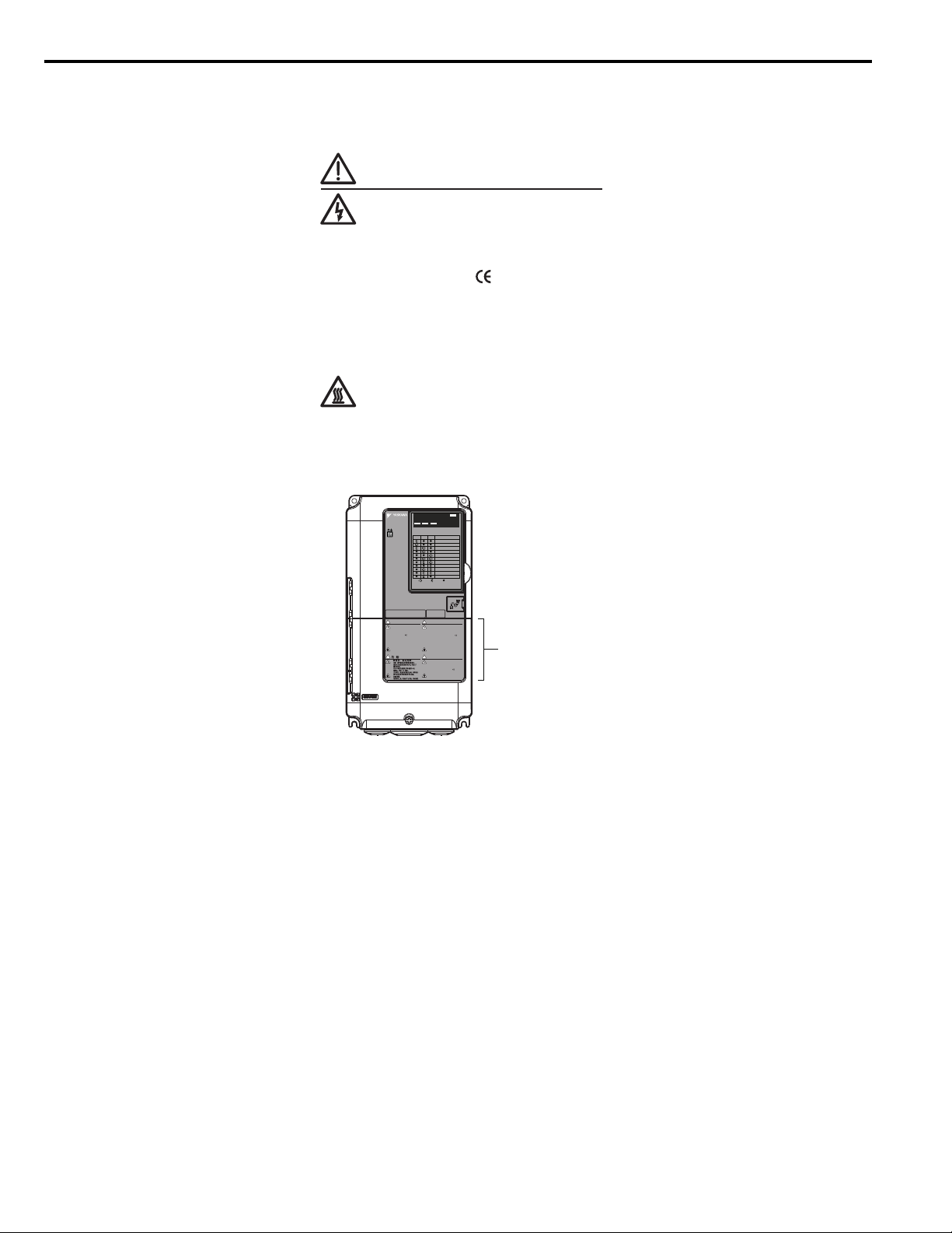
■ Drive Label Warnings
Always heed the warning information listed in Figure 1 in the position shown in Figure 2.
Figure 1
WARNING
Risk of electric shock.
●
Read manual before installing.
●
Wait 5 minutes for capacitor
discharge after disconnecting
power supply.
●
To conform to requirements,
make sure to ground the supply
neutral for 400V class.
●
After opening the manual switch
between the drive and motor,
please wait 5 minutes before
inspecting, performing
maintenance or wiring the drive.
Hot surfaces
●
Top and Side surfaces may
become hot. Do not touch.
Figure 1 Warning Information
Figure 2
PWRLED MONITOR JVOP-184
RUN DS1 DS2
L1000E
RUN DS1 DS2 STATUS
READY
RUN
ALARM(RUN)
PGOH,LT
BB,HBB
EF,SE
OV,UV
OH,OL
OC,GF,SC,PGO
CPF,OFA,OFB,OFC
Other Fault
:LIGHT :BLINK :LIGHT OFF
CIMR-LE2A0012FAA
200V 3Phase 5.5kW/3.7kW
S/N:
WARNING
Risk of electric shock.
●
Read manual before installing.
●
Wait 5 minutes for capacitor
discharge after disconnecting
power supply.
●
To conform to requirements,
make sure to ground the supply
neutral for 400V class.
●
After opening the manual switch
between the drive and motor,
please wait 5 minutes before
inspecting, performing
maintenance or wiring the drive.
Hot surfaces
●
Top and Side surfaces may
become hot. Do not touch.
●
●
●
●
●
AVERTISSMENT
Risque de décharge électrique.
●
Lire le manuel avant l'installation.
●
Attendre 5 minutes après la coupure
de l'alimentation, pour permettre
la décharge des condensateurs.
●
Pour répondre aux exigences , s
assurer que le neutre soit relié
à la terre, pour la série 400V.
●
Après avoir déconnécte la protection
entre le driver et le moteur, veuillez
patienter 5 minutes avain d’effectuer
une opération de montage ou de
câblage du variateur.
Surfaces Chaudes
●
Dessus et cotés du boitier Peuvent
devenir chaud. Ne Pas toucher.
危 険
けが.感電のおそれがあります。
●
据え付け、運転の前には必ず取扱説明書を読むこと。
●
通電中および電源遮断後5分以内はフロントカバー
を外さない事。
●
400V級インバータの場合は、電源の中性点が接地
されていることを確認すること。(対応)
●
保守・点検、配線を行う場合は、出力側開閉器を
遮断後5分待って実施してください。
高温注意
●
インバータ上部、両側面は高温になります。
触らないでください。
NPJT31470-1
Warning Label
Figure 2 Warning Information Position
■ Warranty Information
Restrictions
The drive is not designed or manufactured for use in devices or systems that may directly affect or threaten human lives or
health.
Customers who intend to use the product described in this manual for devices or systems relating to transportation, health
care, space aviation, atomic power, electric power, or in underwater applications must first contact their Yaskawa
representatives or the nearest Yaskawa sales office.
WARNING! Injury to Personnel. This product has been manufactured under strict quality-control guidelines. However, if this product is
to be installed in any location where failure of this product could involve or result in a life-and-death situation or loss of human life or in
a facility where failure may cause a serious accident or physical injury, safety devices must be installed to minimize the likelihood of any
accident.
14 YAS KA WA TOEPYAIL1E01A YASKAWA AC Drive L1000E Quick Start Guide
Page 15
Receiving
1
1 Receiving
YEA_c
om-
Quick Start Guide
P
W
R
L
E
D
M
O
N
I
T
O
R
JV
O
P
-1
8
4
R
U
N
DS
1
D
S2
R
UN
D
S
1
D
S
2
S
TA
T
U
S
R
E
A
D
Y
R
U
N
A
L
A
RM
(
R
U
N)
P
GO
H
,
L
T
B
B
,
H
B
B
E
F
,S
E
O
t
h
er
Fa
u
l
t
O
V
,
U
V
OH
,
O
L
O
C
,
G
F
,
SC
,
P
G
O
C
P
F
,
O
F
A
,
O
F
B
,
O
F
C
:
L
IG
H
T
:
B
L
I
N
K
:
L
IGH
T
O
F
F
PRG : 3580
IND.CONT.EQ.
7J48 B
CIMR-LE2A0018DAC
REV: A
YASKAWA ELECTRIC CORPORATION
MADE IN JAPAN
:
: CIMR-LE2A0018DAA
: AC3PH 200-240V 50/60Hz 15.6A
: AC3PH 0-240V 0-120Hz 17.5A
: 3.5 kg
:
:
: E131457 IP00
PASS
MODEL
C / C
INPUT
OUTPUT
MASS
O / N
S / N
FILE NO
AC drive model
Input specifications
Output specifications
Lot number
Serial number
Software version
Enclosure type
YEA_comm
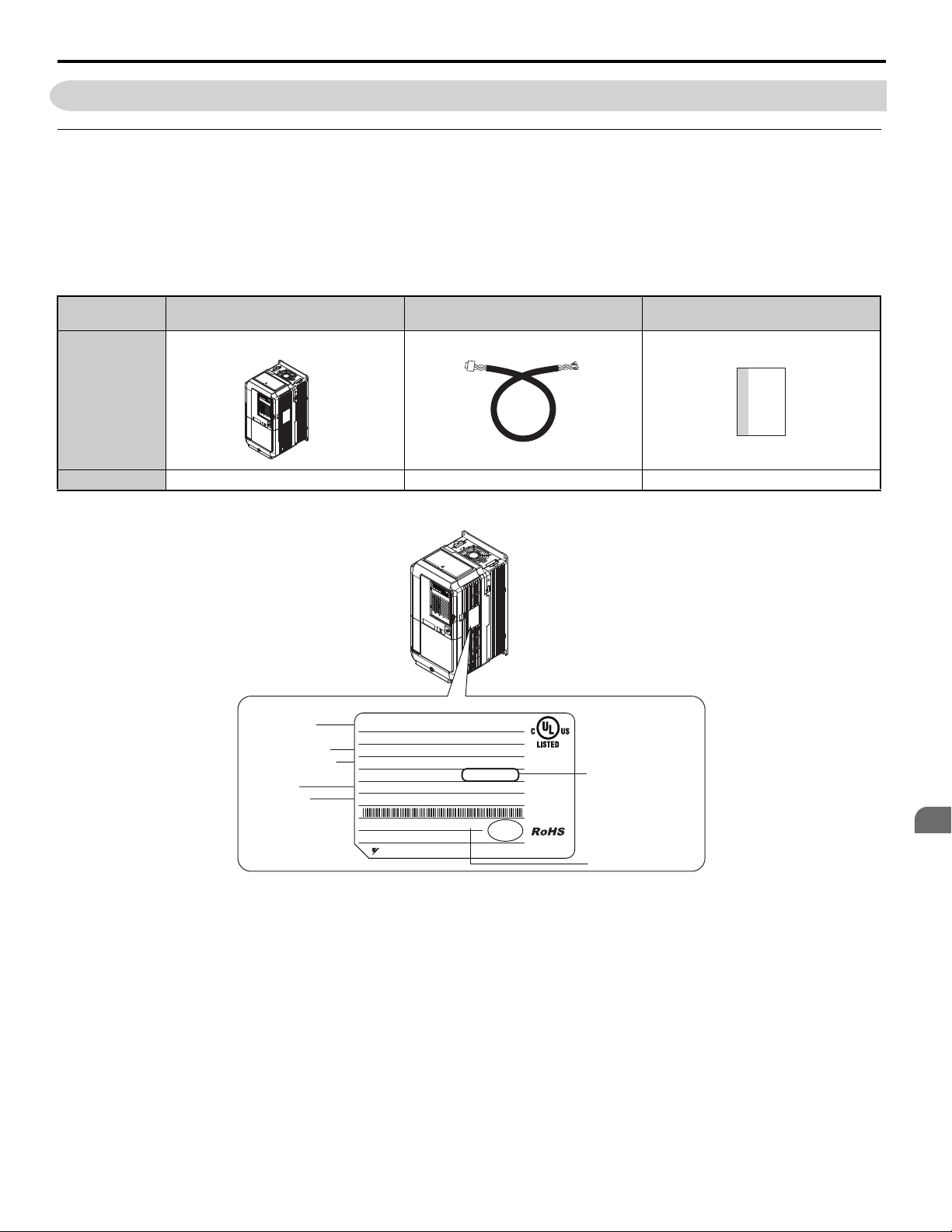
◆ Model Number and Nameplate Check
Please perform the following tasks after receiving the drive:
• Inspect the drive for damage.
If the drive appears damaged upon receipt, contact the shipper immediately.
• Verify receipt of the correct model by checking the information on the nameplate.
• If you have received the wrong model or the drive does not function properly, contact your supplier.
1 Receiving
Description Drive
L
E
D
M
O
N
I
T
O
R
J
V
R
O
U
P
N
1
8
4
D
S
1
D
S
2
P
W
R
R
U
N
D
S
1
D
S
–
2
ST
R
E
A
A
T
D
U
Y
R
S
U
N
A
L
A
R
M
P
(
G
R
O
UN
H
)
,
B
L
T
B
,
H
B
B
E
F
,
S
E
O
V
,
U
V
O
H
,
O
L
O
C
,
G
F
,
C
SC
P
:
F
L
,
,
I
P
O
G
G
F
H
O
O
A
T
t
,
h
O
er
FB
:
F
B
,
a
O
L
u
F
I
l
NK
C
t
:
L
I
G
H
T
O
F
F
Controller Power Supply Cable
for Rescue Operation
Quick Start Guide
Quantity 111
Nameplate
■
Figure 3
YAS KA WA TOEPYAIL1E01A YASKAWA AC Drive L1000E Quick Start Guide 15
Figure 3 Nameplate Information
Page 16
1 Receiving
YEA_common
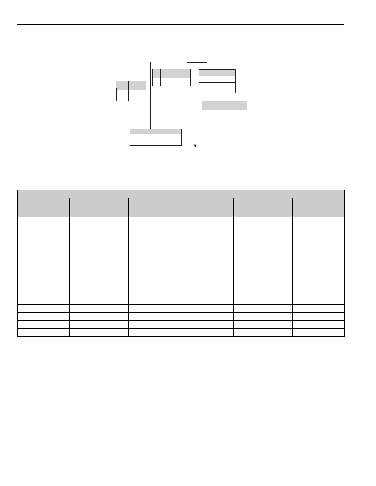
Refer to Table 1
■ Model Number
CIMR- L E 2 A 0018 D A C
Drive
L1000
Series
Region
No.
Code
South
E
America
No. Voltage Class
4
Customized
No.
Specifications
A Standard model
3-phase, 200-240 Vac 2
3-phase, 380-480 Vac
Enclosure Type
No.
IP00
A
IP00 with top
D
protective cover
No.
A Standard
Environmental
Specification
<1>
Design
Revision
Order
<1> Drives with these specifications do not guarantee complete protection for the environmental conditions
indicated.
Table 1 Model Number and Specifications
Three-Phase 200 V Three-Phase 400 V
No.
Max. Motor Capacity
kW (HP)
2A0018 3.7 (5) 17.5 4A0009 3.7 (5) 9.0
2A0022 5.5 (7.5) 21.9 4A0012 5.5 (7.5) 11.5
2A0031 7.5 (10.0) 31.3 4A0019 7.5 (10.0) 18.5
2A0041 11.0 (15.0) 41.3 4A0023 11.0 (15.0) 22.5
2A0059 15.0 (20.0) 58.8 4A0030 15.0 (20.0) 30.0
2A0075 18.5 (25.0) 75.0 4A0039 18.5 (25.0) 38.8
2A0094 22.0 (30.0) 93.8 4A0049 22.0 (30.0) 48.8
2A0106 30.0 (40.0) 106.3 4A0056 30.0 (40.0) 56.3
2A0144 37.0 (50.0) 143.8 4A0075 37.0 (50.0) 75.0
2A0181 45.0 (60.0) 181.3 4A0094 45.0 (60.0) 93.8
2A0225 55.0 (75.0) 225.0 4A0114 55.0 (75.0) 113.8
2A0269 75.0 (100.0) 268.8 4A0140 75.0 (100.0) 140.0
2A0354 90.0 (125.0) 353.8 4A0188 90.0 (125.0) 187.5
2A0432 110.0 (150.0) 432.5 4A0225 110.0 (150.0) 225.0
- - - 4A0260 132.0 (175.0) 260.0
Figure 4
3 minute 50% Duty
Rated Output
Current A
No.
Max. Motor Capacity
kW (HP)
3 minute 50% Duty
Rated Output
Current A
16 YAS KA WA TOEPYAIL1E01A YASKAWA AC Drive L1000E Quick Start Guide
Page 17

2 Mechanical Installation
Mechanical
Installation
2
2 Mechanical Installation
◆ Mechanical Installation
This section outlines specifications, procedures, and the environment for proper mechanical installation of the drive.
CAUTION! Crush Hazard. Carrying the drive by the front cover may cause the main body of the drive to fall, resulting in minor or
moderate injury. Always hold the case when carrying the drive.
■ Installation Environment
Install the drive in an environment matching the specifications below to help prolong the optimum performance life of the
drive.
Table 2 Installation Environment
Environment Conditions
Installation Area Indoors
IP00 enclosure with top protective cover: -10 to +40°C (14 to 104°F)
IP00 enclosure: -10 to +50°C (14 to 122°F)
Ambient Temperature
Humidity 95% RH or less and free of condensation
Storage Temperature -20 to 60°C (-4 to 140°F)
Surrounding Area
Altitude 1000 m (3280 ft.) or lower, up to 3000 m (9842 ft.) with derating (Refer to Altitude Derating on page 162)
Vibration
Orientation Install the drive vertically to maintain maximum cooling effects.
Drive reliability improves in environments without wide temperature fluctuations.
When using the drive in an enclosure panel, install a cooling fan or air conditioner in the area to ensure that the air
temperature inside the enclosure does not exceed the specified levels.
Do not allow ice to develop on the drive.
Install the drive in an area free from:
• oil mist and dust
• metal shavings, oil, water or other foreign materials
• radioactive materials
• combustible materials (e.g., wood)
• harmful gases and liquids
• excessive vibration
• chlorides
• direct sunlight
10 to 20 Hz at 9.8 m/s
20 to 55 Hz at 5.9 m/s2 (2A0018 to 2A0225 and 4A0009 to 4A0188) or 2.0 m/s2 (2A0269 to 2A0432 and 4A0225 to
4A0260)
2
NOTICE: Avoid placing drive peripheral devices, transformers, or other electronics near the drive as the noise created can lead to
erroneous operation. If such devices must be used in close proximity to the drive, take proper steps to shield the drive from noise.
NOTICE: Prevent foreign matter such as metal shavings and wire clippings from falling into the drive during installation. Failure to
comply could result in damage to the drive. Place a temporary cover over the top of the drive during installation. Remove the temporary
cover before startup, as the cover will reduce ventilation and cause the drive to overheat.
YAS KA WA TOEPYAIL1E01A YASKAWA AC Drive L1000E Quick Start Guide 17
Page 18
2 Mechanical Installation
A
A
BB
Side Clearance Top/Bottom Clearance
C
C
D
D
PWRLED MONITOR JVOP-184
RUN DS1 DS2
RUN DS1 DS2 STATUS
READY
RUN
ALARM(RUN)
PGOH,LT
BB,HBB
EF,SE
Other Fault
OV,UV
OH,OL
OC,GF,SC,PGO
CPF,OFA,OFB,OFC
:LIGHT :BLINK :LIGHT OFF
PW
RL
E
D
M
O
N
I
T
O
R
J
V
O
P
-18
4
RU
N
D
S
1
D
S
2
RU
N
D
S1
D
S
2
S
T
A
T
US
R
E
A
D
Y
R
U
N
AL
A
R
M
(
R
UN
)
PG
OH
,
L
T
BB
,
H
B
B
E
F
,
S
E
O
t
h
e
r
F
a
u
lt
O
V,
U
V
O
H
,
O
L
O
C
,
G
F
,
S
C
,
P
G
O
C
PF
,
O
F
A
,
O
F
B
,O
F
C
:
L
I
G
H
T
:
B
LI
N
K
:
L
I
G
H
T O
F
F
YEA_comm
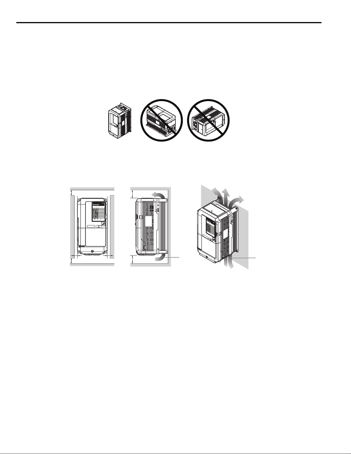
■ Installation Orientation and Spacing
WARNING! Fire Hazard. Provide sufficient cooling when installing the drive inside an enclosed panel or cabinet. Failure to comply
could result in overheating and fire. When drives are placed inside the same enclosure panel, install proper cooling to ensure air
entering the enclosure does not exceed 40°C (104°F).
Installation Orientation
Install the drive upright as illustrated in Figure 4 to maintain proper cooling. Refer to Mechanical Installation on
page 17 for details on installing the drive.
Figure 5
Figure 4 Correct Installation Orientation
Installation Spacing
Figure 5 shows the installation distance required to maintain sufficient space for airflow and wiring.
Figure 6
A – 50 mm (1.97 in.) minimum C – 120 mm (4.72 in.) minimum
B – 30 mm (1.18 in.) minimum D – Airflow direction
Figure 5 Correct Installation Spacing
18 YAS KA WA TOEPYAIL1E01A YASKAWA AC Drive L1000E Quick Start Guide
Page 19

2 Mechanical Installation
Mechanical
Installation
2
■ Instructions on Installation
Eye bolts are used to install the drive or to temporarily lift the drive when replacing it. The drive can be installed in an
enclosure panel or on a wall. Do not leave the drive suspended by the wires in a horizontal or vertical position for long
periods of time. Do not transport the drive over long distances. Read the following precautions and instructions before
installing the drives.
WARNING! Be sure to observe the following instructions and precautions. Failure to comply could result in minor or moderate injury
and damage to the drive from falling equipment.
• Before using wires to suspend the drive vertically and horizontally, make sure that the drive front cover,
terminal blocks and other drive components are securely fixed with screws.
• Do not subject the drive to vibration or impact greater than 1.96 m/s
wires.
• Do not overturn the drive while it is suspended by the wires.
• Do not leave the drive suspended by the wires for long periods of time.
2
(0.2 G) while it is suspended by the
Horizontal Suspension of the Drive (CIMR-LE2A0432 and 4A0260)
To make a wire hanger or frame for use when lifting the drive with a crane, lay the drive in a horizontal position and pass
a wire through the holes of the four eye bolts.
When lifting the drive, confirm that the spring washer is fully closed. If not, the drive may become deformed or damaged
when lifted.
Figure 7
B
A
A – No space between drive and washer C – Space between drive and washer
B – Spring washer: Fully closed D – Spring washer: Open
Figure 6 Details of Spring Washers
D
C
Vertical Suspension of the Drive (CIMR-LE2A0432 and 4A0260)
When vertical suspension of the drive is required in an enclosure panel, the orientation of the eye bolts for these drive
models can be easily changed by turning the eye bolts counterclockwise 90 degrees.
Figure 8
Figure 7 Adjusting Angle of Eye Bolts (CIMR-LE2A0432 and 4A0260)
YAS KA WA TOEPYAIL1E01A YASKAWA AC Drive L1000E Quick Start Guide 19
Page 20

2 Mechanical Installation
YEA_com
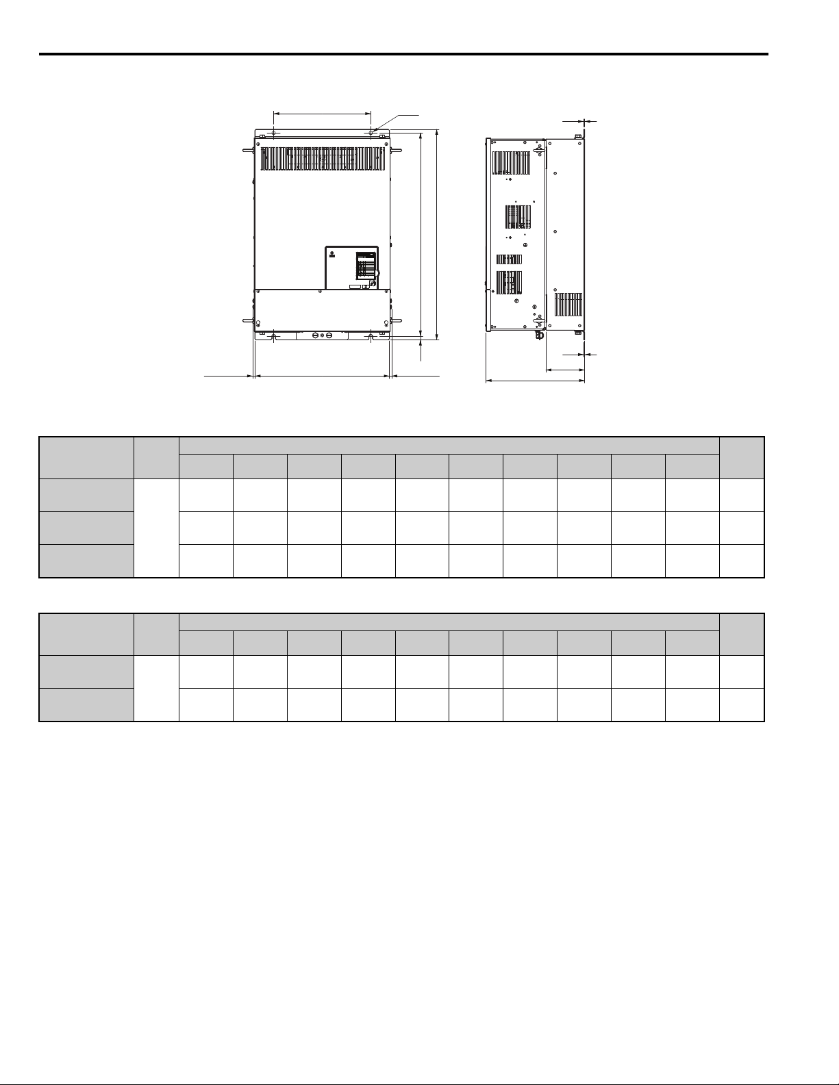
■ Exterior and Mounting Dimensions
IP00 Enclosure Drive with Top Protective Cover
W1
RUN DS1 DS2
RUN DS1 DS2 STATU S
READY
RUN
ALARM(RUN)
PGOH,LT
BB,HBB
EF,SE
OV,UV
OH,OL
OC,GF,SC,PGO
CPF,OFA,OFB,OFC
Other Fault
:LIGHT :BLINK :LIGHT OFF
4-d
1.5
(0.06)
PWRLED MONITOR JVOP-184
W1
RUN DS1 DS2
RUN DS1 DS2 STATUS
:LIGHT :BLINK :LIGHT OFF
READY
RUN
ALARM(RUN)
PGOH,LT
BB,HBB
EF,SE
OV,UV
OH,OL
OC,GF,SC,PGO
CPF,OFA,OFB,OFC
Other Fault
4-d
PWRLED MONITOR JVOP-184
t2
W
Drive Model Figure
2A0018
2A0022
2A0031
2A0041
2A0059
2A0075
2A0094
2A0106
2A0144
1
2
2A0181
2A0225
H
H1
H2
Figure 1
t1
Max 8
D
D1
(0.31)
W
H1
H2
Max 8
(0.31)
Figure 2
H
Table 3 Dimensions: 200 V Class
Dimensions mm (in)
W H D W1 H1 H2 D1 t1 t2 d
140
(5.50)
140
(5.50)
140
(5.50)
140
(5.50)
180
(7.10)
221
(8.70)
221
(8.70)
249
(9.80)
274
(10.80)
325
(12.80)
325
(12.80)
259
(10.20)
259
(10.20)
259
(10.20)
259
(10.20)
300
(11.80)
351
(13.80)
351
(13.80)
399
(15.70)
450
(17.70)
551
(21.70)
551
(21.70)
165
(6.50)
165
(6.50)
168
(6.60)
168
(6.60)
188
(7.40)
198
(7.80)
198
(7.80)
259
(10.20)
259
(10.20)
284
(11.10)
284
(11.10)
122
(4.80)
122
(4.80)
122
(4.80)
122
(4.80)
160
(6.30)
193
(7.60)
193
(7.60)
196
(7.70)
221
(8.70)
259
(10.20)
259
(10.20)
249
(9.80)5(0.20)56(2.20).5(0.20)
249
(9.80)5(0.20)56(2.20).5(0.20)
249
(9.80)5(0.20)56(2.20).5(0.20)
249
(9.80)5(0.20)56(2.20).5(0.20)
284
(11.20)8(0.30)76(3.00).5(0.20)
335
(13.20)8(0.30)79(3.10).5(0.20)
335
(13.20)8(0.30)79(3.10).5(0.20)
386
(15.20)8(0.30)99(3.90)
434
(17.10)8(0.30)99(3.90)
536
(21.10)8(0.30)
536
(21.10)8(0.30)
109
(4.30)
109
(4.30)
.25
(0.10)
.25
(0.10)
.25
(0.10)
.25
(0.10)
D
–M5
–M5
–M5
–M5
–M5
–M6
–M6
.25
(0.10)
.25
(0.10)
.25
(0.10)
.25
(0.10)
M6
M6
M6
M6
t1
D1
Weight
kg (lbs)
3.5
(7.7)
3.5
(7.7)
4.0
(8.8)
4.0
(8.8)
5.6
(12.3)
8.7
(19.2)
9.7
(21.4)
21.0
(46.3)
25.0
(55.1)
37.0
(81.6)
38.0
(83.8)
20 YAS KA WA TOEPYAIL1E01A YASKAWA AC Drive L1000E Quick Start Guide
Page 21

Mechanical
Installation
2
Table 4 Dimensions: 400 V Class
2 Mechanical Installation
Drive Model Figure
4A0009
4A0012
4A0019
4A0023
4A0030
4A0039
4A0049
4A0056
4A0075
4A0094
1
2
4A0114
4A0140
4A0188
Dimensions mm (in)
W H D W1 H1 H2 D1 t1 t2 d
140
(5.50)
140
(5.50)
140
(5.50)
140
(5.50)
180
(7.10)
180
(7.10)
221
(8.70)
249
(9.80)
274
(10.80)
325
(12.80)
325
(12.80)
325
(12.80)
325
(12.80)
259
(10.20)
259
(10.20)
259
(10.20)
259
(10.20)
300
(11.80)
300
(11.80)
351
(13.80)
399
(15.70)
450
(17.70)
511
(20.10)
511
(20.10)
551
(21.70)
551
(21.70)
165
(6.50)
165
(6.50)
168
(6.60)
168
(6.60)
168
(6.60)
188
(7.40)
198
(7.80)
259
(10.20)
259
(10.20)
259
(10.20)
259
(10.20)
282
(11.10)
282
(11.10)
122
(4.80)
122
(4.80)
122
(4.80)
122
(4.80)
160
(6.30)
160
(6.30)
193
(7.60)
196
(7.70)
221
(8.70)
259
(10.20)
259
(10.20)
259
(10.20)
259
(10.20)
249
(9.80)5 (0.20)56(2.20)5(0.20)
249
(9.80)5 (0.20)56(2.20)5(0.20)
249
(9.80)5 (0.20)56(2.20)5(0.20)
249
(9.80)5 (0.20)56(2.20)5(0.20)
284
(11.20)8(0.30)56(2.20)5(0.20)
284
(11.20)8(0.30)76(3.00)5(0.20)
335
(13.20)8(0.30)79(3.10)5(0.20)
–M5
–M5
–M5
–M5
–M5
–M5
–M6
386
(15.20)8(0.30)99(3.90)3(0.10)3(0.10)
434
(17.10)8(0.30)99(3.90)3(0.10)3(0.10)
495
(19.50)8(0.30)
495
(19.50)8(0.30)
536
(21.10)8(0.30)
536
(21.10)8(0.30)
104
(4.10)3(0.10)3(0.10)
104
(4.10)3(0.10)3(0.10)
109
(4.30)3(0.10)3(0.10)
109
(4.30)3(0.10)3(0.10)
M6
M6
M6
M6
M6
M6
Weight
kg (lbs)
3.5
(7.7)
3.5
(7.7)
4.0
(8.6)
4.0
(8.9)
5.4
(11.9)
5.4
(11.9)
8.0
(18.3)
22.0
(46.3)
25.0
(55.1)
36.0
(79.4)
36.0
(79.4)
41.0
(90.4)
42.0
(92.6)
YAS KA WA TOEPYAIL1E01A YASKAWA AC Drive L1000E Quick Start Guide 21
Page 22
2 Mechanical Installation
YEA_com
IP00 Enclosure Drive
W1
RUN DS1 DS2
RUNDS1 DS2 STATUS
:LIGHT :BLINK :LIGHT OFF
4-d
H
PWRLED MONITOR JVOP-184
READY
RUN
ALARM(RUN)
PGOH,LT
BB,HBB
EF,SE
OV,UV
OH,OL
OC,GF,SC,PGO
CPF,OFA,OFB,OFC
Other Fault
H1
t2
Drive Model Figure
2A0269
2A0354
2A0432
1
Drive Model Figure
4A0225
1
4A0260
t1
D1
D
Max 8
(0.31)
H2
W
Max 8
(0.31)
Figure 1
Table 5 Dimensions: 200 V Class
Dimensions mm (in) Weight
W H D W1 H1 H2 D1 t1 t2 d
450
(17.70)
450
(17.70)
500
(19.70)
706
(27.80)
706
(27.80)
800
(31.50)
330
(13.00)
330
(13.00)
330
(13.00)
325
(12.80)
325
(12.80)
371
(14.60)
681
(26.80)13(0.50)
681
(26.80)13(0.50)
772
(30.40)13(0.50)
130
(5.10)3(0.10)3(0.10)
130
(5.10)3(0.10)3(0.10)
130
(5.10)5(0.20)5(0.20)
Table 6 Dimensions: 400 V Class
Dimensions mm (in) Weight
W H D W1 H1 H2 D1 t1 t2 d
450
(17.70)
500
(19.70)
706
(27.80)
800
(31.50)
330
(13.00)
330
(13.00)
325
(12.80)
371
(14.60)
681
(26.80)13(0.50)
772
(30.40)13(0.50)
130
(5.10)3(0.10)3(0.10)
130
(5.10)5(0.20)5(0.20)
M10
M10
M12
M10
M12
kg
(lbs)
76
(167.6)
80
(176.4)
98
(216.1)
kg
(lbs)
79
(174.2)
96
(211.6)
22 YAS KA WA TOEPYAIL1E01A YASKAWA AC Drive L1000E Quick Start Guide
Page 23

3 Electrical Installation
Electrical Installation
3
3 Electrical Installation
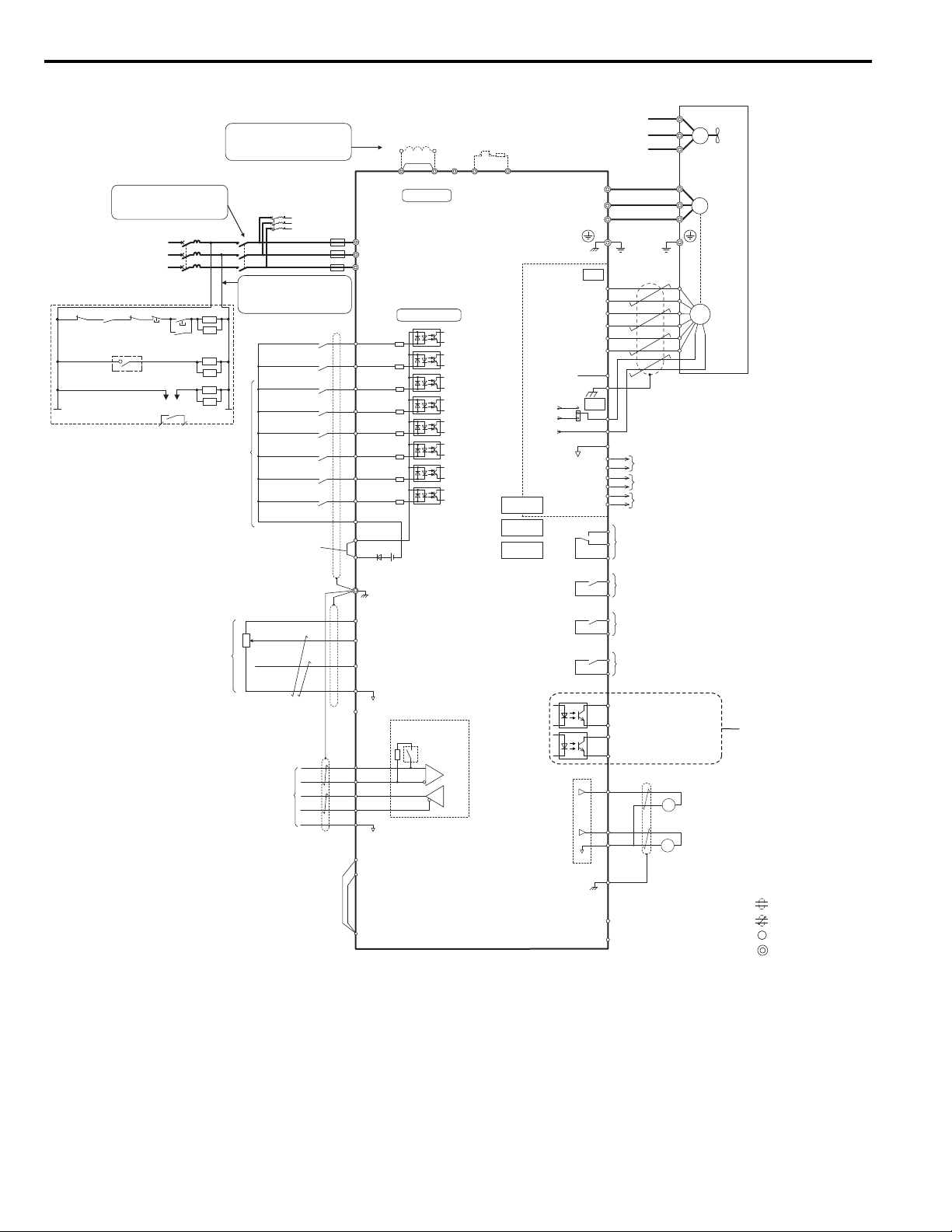
◆ Standard Connection Diagram
Connect the drive and peripheral devices as shown in Figure 8. It is possible to set and run the drive via the digital
operator without connecting digital I/O wiring. This section does not discuss drive operation; Refer to Start-Up
Programming on page 52 for instructions on operating the drive.
WARNING! Sudden Movement Hazard. Ensure holding brake circuits are properly configured, load equipment may fall or drop during
power loss or drive fault, which could result in death or serious injury.
・Provide a separate holding brake if necessary.
・Always construct the external sequence to confirm that the holding brake is activated in the event of an emergency, a power failure, or
an abnormality in the drive.
・When using the drive with an elevator, provide safety measures on the elevator to prevent the elevator from dropping.
NOTICE: Equipment Hazard. Separate motor and/or braking circuit wiring (terminals, U/T1, V/T2, W/T3, +3, +2, +1,(-), B1, B2, from all
other wiring. Place motor wiring within its own conduit or cable tray with appropriate divider, and use shielded motor cable where
appropriate. Improper wiring practices could result in malfunction of drive due to electrical interference.
NOTICE: Inadequate wiring could result in damage to the drive. Install adequate branch circuit short circuit protection per applicable
codes. The drive is suitable for circuits capable of delivering not more than 100,000 RMS symmetrical amperes, 240 Vac maximum
(200 V Class) and 480 Vac maximum (400 V Class).
NOTICE: When the input voltage is 440 V or higher or the wiring distance is greater than 100 meters (328 ft.), pay special attention to
the motor insulation voltage or use a drive rated motor. Failure to comply could lead to motor insulation breakdown.
Note: Do not connect AC control circuit ground to drive enclosure. Improper drive grounding can cause control circuit malfunction.
NOTICE: The minimum load for the multi-function relay output MA-MB-MC is 10 mA. If a circuit requires less than 10 mA (reference
value), connect it to a photocoupler output (P1-C1, P2-C2). Improper application of peripheral devices could result in damage to the
photocoupler output of the drive.
YAS KA WA TOEPYAIL1E01A YASKAWA AC Drive L1000E Quick Start Guide 23
Page 24
3 Electrical Installation
Shield ground terminal
+−+
−
DM
DM
H
1
H2
HC
<10>
R/L1
S/L2
T/L3
Fuse
MC
2MCCB
MB
ON
OFF
THRX
SA
1
2
TRX
MC
MA
TRX
Fault relay
contact
Braking resistor unit
Thermal relay trip contact
MC
MC
SA
SA
THRX
ELCB (MCCB)
R
T
S
Three-phase
power supply
200 to 240 V
50/60 Hz
<14>
2MCCB
r1
s1
t1
MC
Wiring sequence should shut off
power to the drive when a fault
output is triggered.
If running from a 400 V power
supply, a step-down transformer
is needed to reduce the voltage
to 200 V.
P1
P2
C1
C2
Photo Coupler 1
(During Frequency Output)
Photo Coupler 2
(not used)
Digital output
5 to 48 Vdc
2 to 50 mA
(default setting)
+
+
++
Terminals -, +1, +2, B1, B2 are
for connecting options. Never
connect power supply lines to
these terminals
DC link choke
(option)
UX
Thermal relay
(option)
+
+
++
+
−
UX
S
1
S2
S3
S4
S5
S6
S7
A1
A2
0
V
AC
R
R
S
S
IG
Drive
B112
B2
2
kΩ
S8
SC
0 V
FM
AM
AC
E (G)
<1>
<8>
<8>
<9>
<2><3>
−
+24 V
+V
MA
M
1
M2
MB
MC
Jumper
Braking resistor
(option)
Up command / Stop
External Fault
Fault Reset
Multi-step Speed 1
Not Used
Multi-function
digtial inputs
(default setting)
Sink / Source mode
selection wire jumper
(default: Sink)
Multi-function
analog inputs
Power supply +10.5 Vdc, max. 20 mA
Analog Input 1 (Speed Bias)
-10 to +10 Vdc (20 kΩ)
Analog Input 2 (Not used)
-10 to +10 Vdc (20 kΩ)
−V
Power supply, -10.5 Vdc, max. 20 mA
MEMOBUS/Modbus
comm. RS485/422
max. 115.2 kBps
Termination resistor
(120 Ω, 1/2 W)
DIP
Switch S2
Fault relay output
250 Vac, max. 1 A
30 Vdc, max 1 A
(min. 5 Vdc, 10 mA)
Multi-function relay output (Brake Release Command)
250 Vac, max. 1 A
30 Vdc, max 1 A
(min. 5 Vdc, 10 mA)
Multi-function analog output 1
(Output Speed)
-10 to +10 Vdc (2mA)
Multi-function analog output 2
(Output Current)
-10 to +10 Vdc (2mA)
Main Circuit
Control Circuit
shielded line
twisted-pair shielded line
main circuit terminal
control circuit terminal
M3
M4
Multi-function relay output (Motor Contactor Close Command)
250 Vac, max. 1 A
30 Vdc, max 1 A
(min. 5 Vdc, 10 mA)
M5
M6
Multi-function relay output (Drive Ready)
250 Vac, max. 1 A
30 Vdc, max 1 A
(min. 5 Vdc, 10 mA)
SP
SN
FM
+
−
AM
<7>
Down command / Stop
Multi-step Speed 2
Multi-step Speed 3
FE
SD
NC
a+
a-
b-
z-
b+
z+
IP
IG
IP12
IP5
IG
SG
TB2
A pulse monitor signal
B pulse monitor signal
Z pulse monitor signal
CN3
PG
<4>
<2>
A+
A
B
Z
B+
Z+
TB1
PGX3
CN5-C
CN5-B
CN5-A
Option card
connector
M
U/T
1
V/T2
W/T
U/T1
V/T2
W/T3
3
Ground
Cooling fan
<6>
<5>
M
r1
s1
t1
FU
FV
FW
<12>
<13> <14>
<15>
EDM (Safety Electronic Device Monitor)
Safe Disable inputs
<11>
YEA_com
Figure 9
Figure 8 Drive Standard Connection Diagram (example: CIMR-LE2A0041)
<1> Remove the jumper when installing a DC link choke. Models 2A0106 through 2A0432 and 4A0056 through
4A0260 come with a built-in DC link choke.
<2> Set L8-55 to 0 to disable the protection function of the built-in braking transistor of the drive when using an
optional regenerative converter or dynamic braking option.
<3> Set up a thermal relay sequence to disconnect drive main power in the event of an overheat condition on the
dynamic braking option.
<4> Self-cooling motors do not require the same wiring necessary for motors with separate cooling fans.
24 YAS KA WA TOEPYAIL1E01A YASKAWA AC Drive L1000E Quick Start Guide
Page 25

3 Electrical Installation
Electrical Installation
3
<5> Supplying power to the control circuit separately from the main circuit requires a 24 V power supply (option).
<6> For control modes that do not use a motor speed feedback signal, PG option card wiring is not necessary.
<7> This figure illustrates an example of a sequence input to S1 through S8 using a non-powered relay or an NPN
transistor. Install the wire link between terminals SC-SP for Sink mode, between SC-SN for Source mode, or
leave the link out for external power supply. Never short terminals SP and SN, as it will damage the drive.
<8> The maximum output current capacity for the +V and -V terminals on the control circuit is 20 mA. Never short
terminals +V, -V, and AC, as it can cause erroneous operation or damage the drive.
<9> Set DIP switch S2 to the ON position to enable the termination resistor in the last drive in a MEMOBUS/
Modbus network.
<10>The sink/source setting for the Safe Disable input is the same as with the sequence input. Jumper S3 has the
drive set for an external power supply. When not using the Safe Disable input feature, remove the jumper
shorting the input and connect an external power supply. Refer to Sinking/Sourcing Mode Selection for Safe
Disable Inputs on page 50 for instructions.
<11>Disconnect the wire jumper between H1 - HC and H2 - HC when utilizing the Safe Disable input.
<12>Monitor outputs work with devices such as analog frequency meters, ammeters, voltmeters, and wattmeters.
They are not intended for use as a feedback-type of signal.
<13>When the drive is set to trigger a fault output upon activation of the fault reset function (L5-02 = 1), a
sequence to interrupt power when a fault occurs will shut off the power to the drive when the drive attempts a
reset. The default setting for L5-02 is 0 (fault output not active during reset attempt).
<14>Wire fault contact outputs MA, MB, and MC. Wire so that a fault will open the safety circuit and interrupt
drive output.
<15>When using the Programming Mode to edit parameter settings, the drive will not accept an Up/Down
command. If the drive still will not run when an Up/Down command has been entered and no fault is present,
then use the "Drive ready" signal (the default setting for terminal M5-M6) to interlock components.
WARNING! Sudden Movement Hazard. Ensure start/stop and safety circuits are wired properly and in the correct state before
energizing the drive. Failure to comply could result in death or serious injury from moving equipment.
NOTICE: When using the automatic fault reset function with wiring designed to shut off the power supply upon drive fault, make sure
the drive does not trigger a fault output during fault reset (L5-02 = 0, default). Failure to comply will prevent the automatic fault reset
function from working properly.
YAS KA WA TOEPYAIL1E01A YASKAWA AC Drive L1000E Quick Start Guide 25
Page 26

3 Electrical Installation
+1
–
R/L1
S/L2
T/L3
U/T1
V/T2
W/T3
B1 B2
DC link
choke
+
Relay
Gate board
Control
board
Operator
Current
sensor
YEA_
com-
YEA_
com-
YEA_
com-
◆ Main Circuit Connection Diagram
Refer to the Figure 9 when wiring the main circuit of the drive. Connections may vary based on drive capacity. The DC
power supply for the main circuit also provides power to the control circuit.
NOTICE: Do not use the negative DC bus terminal “-” as a ground terminal. This terminal is at high DC voltage potential. Improper
wiring connections could damage the drive.
NOTICE: Equipment Hazard. Separate motor and/or braking circuit wiring (terminals, U/T1, V/T2, W/T3, +3, +2, +1,(-), B1, B2, from all
other wiring. Place motor wiring within its own conduit or cable tray with appropriate divider, and use shielded motor cable where
appropriate. Improper wiring practices could result in malfunction of drive due to electrical interference.
+1
+2
R/L1
S/L2
T/L3
2A0018 to 2A0094
4A0009 to 4A0049
B1 B2
Relay
+
–
Gate board
Control
board
Current
sensor
Operator
U/T1
V/T2
W/T3
2A0181 and 2A0225
4A0094 to 4A0140
+3
2A0106 and 2A0144
4A00456 and 4A0075
2A0269 to 2A0432
4A0188 to 4A0260
+3
R/L1
S/L2
T/L3
+1
–
DC link
choke
Relay
24 V
Power
Supply
+
Gate board
Control
board
Current
sensor
Operator
U/T1
V/T2
W/T3
+1
R/L1
S/L2
T/L3
–
26 YAS KA WA TOEPYAIL1E01A YASKAWA AC Drive L1000E Quick Start Guide
DC link
choke
Relay
+
Gate board
Control
board
Current
sensor
U/T1
V/T2
W/T3
Operator
Figure 9 Drive Main Circuit Configurations
Page 27

3 Electrical Installation
Electrical Installation
3
YEA_common
YEA_common
YEA_common
◆ Terminal Cover
Follow the procedure below to remove the terminal cover for wiring and to reattach the terminal cover after wiring is
complete.
Removing/Reattaching the Terminal Cover
■
Removing the Terminal Cover
Models 2A0018 to 2A0094 and 4A0009 to 4A0049
1. Loosen the terminal cover screw using a #2 Phillips screwdriver. Screw sizes vary by drive model.
Figure 10
Figure 10 Removing the Terminal Cover
2. Push in on the tab located on the bottom of the terminal cover and gently pull forward to remove the terminal
Figure 11
cover.
Figure 11 Removing the Terminal Cover
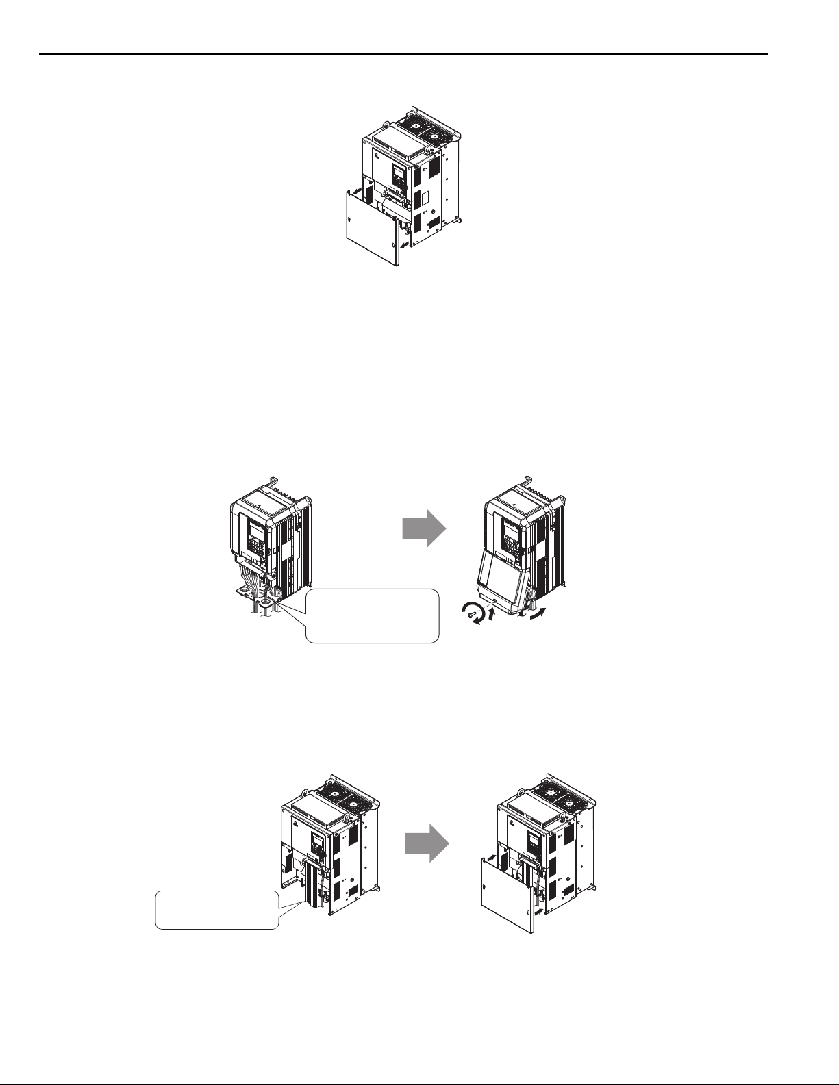
Models 2A0106 to 2A0432 and 4A0056 to 4A0260
1. Loosen the screws on the terminal cover, then pull down on the cover.
CAUTION! Do not completely remove the cover screws, just loosen them. If the cover screws are removed completely, the terminal
cover may fall off causing an injury.
Note: The shape of the terminal covers and the numbers of screws differ depending on the drive models.
Figure 12
Figure 12 Removing the Terminal Cover
YAS KA WA TOEPYAIL1E01A YASKAWA AC Drive L1000E Quick Start Guide 27
Page 28
3 Electrical Installation
YEA_common
Connect ground wiring first,
followed by the main circuit,
and then wire the control circuit.
Power lines and signal wiring
exit through the opening provided.
YEA_common
Connect ground wiring first,
followed by the main circuit,
and then wire the control circuit.
YEA_common
2. Pull forward on the terminal cover to free it from the drive.
Figure 13
Figure 13 Removing the Terminal Cover
Reattaching the Terminal Cover
Models 2A0018 to 2A0094 and 4A0009 to 4A0049
Power lines and signal wiring should pass through the opening provided. Refer to Wiring the Main Circuit Terminal on
page 42 and Wiring the Control Circuit Terminal on page 46 for details on wiring.
NOTICE: Equipment Hazard. Separate motor and/or braking circuit wiring (terminals, U/T1, V/T2, W/T3, +3, +2, +1,(-), B1, B2, from all
other wiring. Place motor wiring within its own conduit or cable tray with appropriate divider, and use shielded motor cable where
appropriate. Improper wiring practices could result in malfunction of drive due to electrical interference.
Reattach the terminal cover after completing the wiring to the drive and other devices.
Figure 14
Figure 14 Reattaching the Terminal Cover
Models 2A0106 to 2A0432 and 4A0056 to 4A0260
After wiring the terminal board and other devices, double-check connections and reattach the terminal cover. Refer to
Wiring the Main Circuit Terminal on page 42 and Wiring the Control Circuit Terminal on page 46 for details on
wiring.
Figure 15
Figure 15 Reattaching the Terminal Cover
28 YAS KA WA TOEPYAIL1E01A YASKAWA AC Drive L1000E Quick Start Guide
Page 29

3 Electrical Installation
Electrical Installation
3
YEA_common
P
W
R
L
ED
M
O
N
I
T
O
R
J
V
O
P
1
84
R
U
N
D
S
1
D
S
2
R
U
N
D
S
1
D
S2
STA
T
U
S
R
E
A
DY
R
UN
A
L
A
R
M
(
R
UN)
P
G
OH,
LT
B
B
,
H
B
B
EF,S
E
O
t
h
e
r Fa
u
l
t
O
V
,
U
V
O
H,O
L
O
C
,
GF
,
SC
,
P
G
O
C
PF
,
O
F
A
,O
F
B
,
OFC
:L
IG
H
T
:
B
L
I
N
K
:
LIGH
T
O
F
F
PW
R
L
E
D
M
O
N
I
T
O
R
J
V
O
P
1
8
4
R
U
N
D
S
1
D
S
2
R
U
N
D
S
1
D
S
2
S
TA
T
U
S
R
E
A
D
Y
R
U
N
A
L
A
R
M(
R
U
N
)
PG
O
H
,
L
T
B
B
,
H
B
B
E
F
,
S
E
O
t
h
e
r
Fau
l
t
O
V
,
U
V
O
H
,
O
L
O
C
,
G
F
,
S
C
,
P
G
O
C
P
F
,
O
F
A
,
O
F
B
,
O
F
C
:
L
I
G
H
T
:
B
L
I
N
K
:
L
I
G
H
T
OF
F
YEA_common
P
W
R
L
E
D
M
O
N
I
T
O
R
J
V
O
P
1
8
4
R
U
N
D
S1
D
S
2
R
UN
DS
1
D
S
2
ST
A
T
U
S
RE
A
D
Y
R
U
N
A
L
A
R
M
(
R
UN
)
P
G
O
H
,
L
T
B
B,
H
BB
E
F
,
S
E
O
t
h
er
F
a
u
l
t
O
V
,
UV
O
H
,
O
L
O
C
,
G
F
,
SC
,
P
G
O
C
P
F
,
O
F
A,
O
FB
,
O
F
C
:
L
I
G
H
T
:
B
L
I
N
K
:L
I
G
H
T
O
F
F
YEA_commo
◆ LED Monitor and Front Cover
Detach the LED monitor from the drive for remote operation or when opening the front cover to install an option card.
Note: Be sure to remove the LED monitor prior to opening or reattaching the front cover. Leaving the LED monitor plugged into the
drive when removing the front cover can result in erroneous operation caused by a poor connection. Firmly fasten the front cover
back into place before reattaching the LED monitor.
■ Removing/Reattaching the LED Monitor
Removing the LED Monitor
While pressing on the tab located on the right side of the LED monitor, pull the LED monitor forward to remove it from
the drive.
Figure 16
Figure 16 Removing the LED Monitor
Reattaching the LED Monitor
Insert the LED monitor into the opening in the top cover while aligning it with the notches on the left side of the opening.
Next, press gently on the right side of the LED monitor until it clicks into place.
Figure 17
Figure 17 Reattaching the LED Monitor
■ Removing/Reattaching the Front Cover
Removing the Front Cover
Models 2A0018 to 2A0094 and 4A0009 to 4A0049
After removing the terminal cover and the LED monitor, loosen the screw that affixes the front cover (models 2A0059,
4A0030, and 4A0039 do not use a screw to affix the front cover). Pinch inwards on the tabs found on each side of the
front cover, then pull forward to remove it from the drive.
Figure 18
Figure 18 Remove the Front Cover (Models 2A0018 to 2A0094 and 4A0009 to 4A0049)
YAS KA WA TOEPYAIL1E01A YASKAWA AC Drive L1000E Quick Start Guide 29
Page 30

3 Electrical Installation
HookHook
Front cover
installation screw
Free hooks on both
sides of the cover
Models 2A0106 to 2A0432 and 4A0056 to 4A0260
1. Remove the terminal cover and the LED monitor.
2. Loosen the installation screw on the front cover.
3. Use a straight-edge screwdriver to loosen the hooks on each side of the cover that hold it in place.
Figure 19
Figure 19 Remove the Front Cover (Models 2A0106 to 2A0432 and 4A0056 to 4A0260)
4. Unhook the left side of the front cover then swing the left side towards you as shown in Figure 20 until the cover
Figure 20
comes off.
Figure 20 Remove the Front Cover (Models 2A0106 to 2A0432 and 4A0056 to 4A0260)
Reattaching the Front Cover
Models 2A0018 to 2A0094 and 4A0009 to 4A0049
Reverse the instructions given in Remove the Front Cover (Models 2A0018 to 2A0094 and 4A0009 to 4A0049) on
page 29 to reattach the front cover. Pinch inwards on the hooks found on each side of the front cover while guiding it back
into the drive. Make sure it clicks firmly into place.
30 YAS KA WA TOEPYAIL1E01A YASKAWA AC Drive L1000E Quick Start Guide
Page 31

Electrical Installation
3
Models 2A0018 to 2A0094 and 4A0009 to 4A0049
1. Slide the front cover so the hooks on the top connect to the drive.
Figure 21
Figure 21 Reattach the Front Cover (2A0106 to 2A0432 and 4A0056 to 4A0260)
2. After connecting the hooks to the drive, press firmly on the cover to lock it into place.
3 Electrical Installation
YAS KA WA TOEPYAIL1E01A YASKAWA AC Drive L1000E Quick Start Guide 31
Page 32

3 Electrical Installation
◆ Main Circuit Wiring
This section describes the functions, specifications, and procedures required to safely and properly wire the main circuit
in the drive.
NOTICE: Only connect recommended devices to the drives braking transistor terminals. Failure to comply could result in damage to
the drive or braking circuit. Carefully review instruction manual TOBP C720600 0
NOTICE: Do not use the negative DC bus terminal “-” as a ground terminal. This terminal is at high DC voltage potential.
Improper wiring connections could damage the drive.
NOTICE: Equipment Hazard. Separate motor and/or braking circuit wiring (terminals, U/T1, V/T2, W/T3, +3, +2, +1,(-), B1, B2, from all
other wiring. Place motor wiring within its own conduit or cable tray with appropriate divider, and use shielded motor cable where
appropriate. Improper wiring practices could result in malfunction of drive due to electrical interference.
NOTICE: Equipment Hazard. Comply with proper wiring practices. The motor may run in reverse if the phase order is backward,
causing incorrect elevator direction movement. Connect motor input terminals U, V and W to drive output terminals U/T1,V/T2, and W/
T3. The phase order for the drive and motor should match.
NOTICE: Do not solder the ends of wire connections to the drive. Soldered wiring connections can loosen over time. Improper wiring
practices could result in drive malfunction due to loose terminal connections.
NOTICE: Do not switch the drive input to start or stop the motor. Frequently switching the drive on and off shortens the life of the DC
bus charge circuit and the DC bus capacitors, and can cause premature drive failures. For the full performance life, refrain from
switching the drive on and off more than once every 30 minutes.
when connecting a braking option to the drive.
■ Main Circuit Terminal Functions
Table 7 Main Circuit Terminal Functions
Terminal Type
200 V
Class
400 V
Class
Drive
Model
R/L1
T/L3
U/T1
W/T3
B1
B2
+2 • DC link choke
+1
–
+3 not available
2A0018 to 2A0094 2A0106, 2A0144 2A0181 to 2A0432
4A0009 to 4A0049 4A0056, 4A0075 4A0094 to 4A0260
Main circuit power supply input
Drive output
Braking resistor
connection (+1, +2)
(remove the shorting
bar between +1 and
+2)
• DC power supply
input
(+1, –)
For 200 V class: 100 Ω or less
For 400 V class: 10 Ω or less
• DC power supply
not available
input
(+1, –)
Not available
• DC power supply
input (+1, –)
• Braking unit
connection (+3, –)
Function Page
Connects line power to the drive 24S/L2
Connects to the motor 24V/T2
Available for connecting a braking
resistor or a braking resistor unit option
For connection
• of the drive to a DC power supply
(terminals +1 and – are not UL
approved)
• of dynamic braking options
Grounding terminal 41
–
–
Note: Use terminal B1 and - when installing the braking unit (CDBR type) to the drives with built-in braking transistor (2A0018 to
2A0144, 4A0009 to 4A0075).
32 YAS KA WA TOEPYAIL1E01A YASKAWA AC Drive L1000E Quick Start Guide
Page 33

3 Electrical Installation
Electrical Installation
3
3
■ Wire Gauges and Tightening Torque
Use the tables in this section to select the appropriate wires and crimp terminals.
Gauges listed in the tables are for use in the United States.
Note: 1. Wire gauge recommendations based on drive continuous current ratings using 75°C (167°F) 600 Vac vinyl-sheathed wire assuming
ambient temperature within 40°C (104°F) and wiring distance less than 100 m (328 ft.).
2. Terminals B1, B2, -, +1, +2, and +3, are for connecting a DC link choke, braking resistor or DC power supply. Do not connect other
nonspecific devices to these terminals.
• Consider the amount of voltage drop when selecting wire gauges. Increase the wire gauge when the voltage drop is
greater than 2% of motor rated voltage. Ensure the wire gauge is suitable for the terminal block. Use the following
formula to calculate the amount of voltage drop:
Line drop voltage (V) = × wire resistance (Ω/km) × wire length (m) × current (A) × 10
-3
• Refer to instruction manual TOBP C720600 0 for braking transistor option or braking resistor option wire gauges.
• Use terminal +1 and the negative terminal when connecting a regenerative converter or a regen unit.
• Use terminal B1 and - when installing the braking unit to the drives with built-in braking transistor (2A0018 to 2A0144,
4A0009 to 4A0075).
• Refer to UL Standards Compliance on page 219 for information on UL compliance.
Yaskawa recommends using closed-loop crimp terminals on all drive models. UL/cUL approval requires the use of
closed-loop crimp terminals when wiring the drive main circuit terminals on models 2A0106 to 2A0432 and 4A0056 to
4A0260. Use only the tools recommended by the terminal manufacturer for crimping. Refer to Closed-Loop Crimp
Terminal Size on page 226 for closed-loop crimp terminal recommendations.
The wire gauges listed in the following tables are Yaskawa recommendations. Refer to local codes for proper wire gauge
selections.
YAS KA WA TOEPYAIL1E01A YASKAWA AC Drive L1000E Quick Start Guide 33
Page 34

3 Electrical Installation
Three-Phase 200 V Class
Table 8 Wire Gauge and Torque Specifications (Three-Phase 200 V Class)
Drive Model Termi nal
R/L1, S/L2, T/L3
U/T1, V/T2, W/T3
2A0018
2A0022
2A0031
2A0041
2A0059
–, +1, +2 –
B1, B2 –
R/L1, S/L2, T/L3
U/T1, V/T2, W/T3
–, +1, +2 –
B1, B2 –
R/L1, S/L2, T/L3
U/T1, V/T2, W/T3
–, +1, +2 –
B1, B2 –
R/L1, S/L2, T/L3
U/T1, V/T2, W/T3
–, +1, +2 –
B1, B2 –
R/L1, S/L2, T/L3
U/T1, V/T2, W/T3
–, +1, +2 –
B1, B2 –
Recommended
Wire Size
mm2 (AWG, kcmil)
6.0
(10)
6.0
(10)
6.0
(10)
6.0
(10)
6.0
(10)
6.0
(10)
10
(8)
10
(8)
10
(8)
16
(6)
16
(6)
10
(8)
25
(4)
25
(4)
16
(6)
Wire Range
mm2 (AWG, kcmil)
2.5 to 6.0
(14 to 10)
2.5 to 6.0
(14 to 10)
2.5 to 6.0
(14 to 10)
2.5 to 6.0
(14 to 10)
2.5 to 6.0
(14 to 10)
2.5 to 6.0
(14 to 10)
2.5 to 6.0
(14 to 10)
4.0 to 6.0
(12 to 10)
2.5 to 6.0
(14 to 10)
4.0 to 6.0
(12 to 10)
2.5 to 16
(12 to 6)
2.5 to 16
(12 to 6)
6.0 to 16
(10 to 6)
4.0 to 6.0
(12 to 10)
6.0 to 10
(10 to 8)
2.5 to 16
(12 to 6)
2.5 to 16
(12 to 6)
16
(6)
4.0 to 6.0
(12 to 10)
6.0 to 10
(10 to 8)
16 to 25
(6 to 4)
16 to 25
(6 to 4)
16 to 25
(6 to 4)
6.0 to 10
(10 to 6)
10 to 16
(8 to 6)
Screw
Size
M4
M4
M4
M5
M4
M5
M6
M5
M6
Tightening Torque
N•m (lb.in.)
1.2 to 1.5
(10.6 to 13.3)
1.2 to 1.5
(10.6 to 13.3)
1.2 to 1.5
(10.6 to 13.3)
2 to 2.5
(17.7 to 22.1)
1.2 to 1.5
(10.6 to 13.3)
2 to 2.5
(17.7 to 22.1)
4 to 6
(35.4 to 53.1)
2 to 2.5
(17.7 to 22.1)
4 to 6
(35.4 to 53.1)
34 YAS KA WA TOEPYAIL1E01A YASKAWA AC Drive L1000E Quick Start Guide
Page 35

3 Electrical Installation
Electrical Installation
3
Drive Model Term ina l
R/L1, S/L2, T/L3
U/T1, V/T2, W/T3
2A0075
2A0094
2A0106
2A0144
2A0181
–, +1, +2 –
B1, B2 –
R/L1, S/L2, T/L3
U/T1, V/T2, W/T3
–, +1, +2 – 25 to 35
B1, B2 –
R/L1, S/L2, T/L3
U/T1, V/T2, W/T3
–, +1 –
B1, B2 –
R/L1, S/L2, T/L3
U/T1, V/T2, W/T3
–, +1 –
B1, B2 –
R/L1, S/L2, T/L3
U/T1, V/T2, W/T3
–, +1 –
+3 –
Recommended
Wire Size
mm2 (AWG, kcmil)
35
(3)
35
(3)
16
(6)
35
(2)
16 × 2P
(6 × 2P)
16
(6)
70
(1/0)
70
(1/0)
16
(6)
70
(2/0)
95
(3/0)
25
(4)
95
(4/0)
95
(4/0)
25
(4)
Wire Range
mm2 (AWG, kcmil)
6.0 to 35
(10 to 2)
6.0 to 35
(10 to 2)
16 to 25
(4 to 3)
10 to 16
(8 to 6)
16 to 25
(6 to 4)
6.0 to 35
(10 to 2)
6.0 to 35
(10 to 2)
(3 to 2)
16
(6)
16 to 25
(6 to 4)
6.0 to 50
(10 to 1/0)
6.0 to 50
(10 to 1/0)
35 to 50
(2 to 1/0)
16 to 50
(6 to 1/0)
16 to 25
(6 to 4)
6.0 to 95
(10 to 3/0)
6.0 to 95
(10 to 3/0)
50 to 70
(1/0 to 3/0)
25 to 70
(4 to 2/0)
25
(4)
70 to 95
(1/0 to 4/0)
70 to 95
(1/0 to 4/0)
50 to 95
(1 to 4/0)
70 to 95
(1/0 to 4/0)
25 to 35
(4 to 2)
Screw
Size
M8
M5
M6
M8
M5
M6
M8
M10
M8
M10
Tightening Torque
N•m (lb.in.)
9 to11
(79.7 to 97.4)
2 to 2.5
(17.7 to 22.1)
4 to 6
(35.4 to 53.1)
9 to11
(79.7 to 97.4)
2 to 2.5
(17.7 to 22.1)
4 to 6
(35.4 to 53.1)
9 to 11
(79.7 to 97.4)
18 to 23
(159 to 204)
9 to 11
(79.7 to 97.4)
18 to 23
(159 to 204)
YAS KA WA TOEPYAIL1E01A YASKAWA AC Drive L1000E Quick Start Guide 35
Page 36

3 Electrical Installation
Drive Model Termi nal
R/L1, S/L2, T/L3
U/T1, V/T2, W/T3
2A0225
2A0269
2A0354
2A0432
–, +1 –
+3 –
R/L1, S/L2, T/L3
U/T1, V/T2, W/T3
–, +1 –
+3 –
R/L1, S/L2, T/L3
U/T1, V/T2, W/T3
–, +1 –
+3 –
R/L1, S/L2, T/L3
U/T1, V/T2, W/T3
–, +1 –
+3 –
Recommended
Wire Size
mm2 (AWG, kcmil)
70 × 2P
(1/0 × 2P)
70 × 2P
(1/0 × 2P)
25
(4)
95 × 2P
(3/0 × 2P)
95 × 2P
(3/0 × 2P)
35
(3)
120 × 2P
(4/0 × 2P)
120 × 2P
(4/0 × 2P)
35
(2)
150 × 2P
(250 × 2P)
185 × 2P
(300 × 2P)
50
(1)
Wire Range
mm2 (AWG, kcmil)
70 to 95
(1/0 to 4/0)
70 to 95
(1/0 to 4/0)
50 to 95
(1 to 4/0)
70 to 95
(1/0 to 4/0)
25 to 50
(4 to 1/0)
95 to 150
(3/0 to 300)
95 to 150
(3/0 to 300)
95 to 150
(3/0 to 300)
35 to 150
(2 to 300)
35 to 150
(2 to 300)
95 to 150
(3/0 to 300)
95 to 150
(3/0 to 300)
95 to 150
(3/0 to 300)
95 to 150
(3/0 to 300)
35 to 150
(2 to 300)
95 to 300
(4/0 to 600)
95 to 300
(4/0 to 600)
120 to 300
(250 to 600)
70 to 300
(3/0 to 600)
120 to 240
(1 to 350)
Screw
Size
M10
M12
M10
M12
M12
M10
M12
M12
M10
M12
Tightening Torque
N•m (lb.in.)
18 to 23
(159 to 204)
32 to 40
(283 to 354)
18 to 23
(159 to 204)
32 to 40
(283 to 354)
32 to 40
(283 to 354)
18 to 23
(159 to 204)
32 to 40
(283 to 354)
32 to 40
(283 to 354)
18 to 23
(159 to 204)
32 to 40
(283 to 354)
Note: When connecting peripheral devices and options to the terminals –, +1, +3, B1, and B2, refer to the instruction manuals for each
device. For more information, contact Yaskawa or your nearest sales representative.
36 YAS KA WA TOEPYAIL1E01A YASKAWA AC Drive L1000E Quick Start Guide
Page 37

Electrical Installation
3
Three-Phase 400 V Class
Table 9 Wire Gauge and Torque Specifications (Three-Phase 400 V Class)
3 Electrical Installation
Drive Model Term ina l
R/L1, S/L2, T/L3
U/T1, V/T2, W/T3
4A0009
4A0012
4A0019
4A0023
4A0030
–, +1, +2 –
B1, B2 –
R/L1, S/L2, T/L3
U/T1, V/T2, W/T3
–, +1, +2 –
B1, B2 –
R/L1, S/L2, T/L3
U/T1, V/T2, W/T3
–, +1, +2 –
B1, B2 –
R/L1, S/L2, T/L3
U/T1, V/T2, W/T3
–, +1, +2 –
B1, B2 –
R/L1, S/L2, T/L3
U/T1, V/T2, W/T3
–, +1, +2 –
B1, B2 –
Recommended
Wire Size
mm2 (AWG, kcmil)
2.5
(14)
2.5
(14)
6.0
(10)
4.0
(12)
2.5
(14)
6.0
(10)
6.0
(10)
6.0
(10)
6.0
(10)
6.0
(10)
6.0
(10)
6.0
(10)
10
(8)
10
(8)
10
(8)
Wire Range
mm2 (AWG, kcmil)
2.5 to 6.0
(14 to 10)
2.5 to 6.0
(14 to 10)
2.5 to 6.0
(14 to 10)
2.5 to 6.0
(14 to 10)
2.5 to 6.0
(14 to 10)
2.5 to 6.0
(14 to 10)
2.5 to 6.0
(14 to 10)
2.5 to 6.0
(14 to 10)
2.5 to 6.0
(14 to 10)
2.5 to 6.0
(14 to 10)
2.5 to 16
(12 to 6)
2.5 to 16
(12 to 6)
4.0 to 16
(12 to 6)
4.0 to 6.0
(12 to 10)
2.5 to 6.0
(14 to 10)
2.5 to 16
(12 to 6)
2.5 to 16
(12 to 6)
4.0 to 16
(12 to 6)
4.0 to 6.0
(12 to 10)
4.0 to 6.0
(12 to 10)
6.0 to 16
(10 to 6)
6.0 to 16
(10 to 6)
6.0 to 16
(10 to 6)
6.0 to 10
(10 to 8)
6.0 to 10
(10 to 8)
Screw
Size
M4
M4
M4
M5
M4
M5
M5
M5
M6
Tightening Torque
N•m (lb.in.)
1.2 to 1.5
(10.6 to 13.3)
1.2 to 1.5
(10.6 to 13.3)
1.2 to 1.5
(10.6 to 13.3)
2 to 2.5
(17.7 to 22.1)
1.2 to 1.5
(10.6 to 13.3)
2 to 2.5
(17.7 to 22.1)
3.6 to 4.0
(31.8 to 35.4)
2.7 to 3.0
(23.9 to 26.6)
4 to 6
(35.4 to 53.1)
YAS KA WA TOEPYAIL1E01A YASKAWA AC Drive L1000E Quick Start Guide 37
Page 38

3 Electrical Installation
Drive Model Termi nal
R/L1, S/L2, T/L3
U/T1, V/T2, W/T3
4A0039
4A0049
4A0056
4A0075
4A0094
–, +1, +2 –
B1, B2 –
R/L1, S/L2, T/L3
U/T1, V/T2, W/T3
–, +1, +2 –
B1, B2 –
R/L1, S/L2, T/L3
U/T1, V/T2, W/T3
–, +1 –
B1, B2 –
R/L1, S/L2, T/L3
U/T1, V/T2, W/T3
–, +1 –
B1, B2 –
R/L1, S/L2, T/L3
U/T1, V/T2, W/T3
–, +1 –
+3 –
Recommended
Wire Size
mm2 (AWG, kcmil)
16
(6)
10
(8)
16
(6)
16
(6)
16
(6)
16
(6)
25
(4)
25
(4)
16
(6)
35
(3)
35
(3)
16
(6)
35
(2)
50
(1)
25
(4)
Wire Range
mm2 (AWG, kcmil)
6.0 to 16
(10 to 6)
6.0 to 16
(10 to 6)
16
(6)
6.0 to 10
(10 to 8)
6.0 to 16
(10 to 6)
16 to 25
(6 to 4)
16 to 25
(6 to 4)
16 to 25
(6 to 4)
6.0 to 10
(10 to 8)
10 to 16
(8 to 6)
6.0 to 50
(10 to 1/0)
6.0 to 50
(10 to 1/0)
16 to 35
(6 to 1)
10 to 16
(8 to 4)
10 to 16
(8 to 6)
6.0 to 70
(10 to 3/0)
6.0 to 70
(10 to 3/0)
25 to 35
(4 to 1)
16 to 25
(6 to 3)
16
to 25
(6)
16 to 120
(6 to 250)
16 to 120
(6 to 250)
25 to 50
(3 to 1/0)
16 to 50
(6 to 1/0)
16 to 25
(6 to 4)
Screw
Size
M5
M5
M6
M6
M5
M6
M8
M8
M8
Tightening Torque
N•m (lb.in.)
3.6 to 4.0
(31.8 to 35.4)
2.7 to 3.0
(23.9 to 26.6)
4 to 6
(35.4 to 53.1)
4 to 6
(35.4 to 53.1)
2 to 2.5
(17.7 to 22.1)
4 to 6
(35.4 to 53.1)
9 to 11
(79.7 to 97.4)
9 to 11
(79.7 to 97.4)
9 to 11
(79.7 to 97.4)
38 YAS KA WA TOEPYAIL1E01A YASKAWA AC Drive L1000E Quick Start Guide
Page 39

3 Electrical Installation
Electrical Installation
3
Drive Model Term ina l
R/L1, S/L2, T/L3
U/T1, V/T2, W/T3
4A0114
4A0140
4A0188
4A0225
4A0260
–, +1 –
+3 –
R/L1, S/L2, T/L3
U/T1, V/T2, W/T3
–, +1 –
+3 –
R/L1, S/L2, T/L3
U/T1, V/T2, W/T3
–, +1 –
+3 –
R/L1, S/L2, T/L3
U/T1, V/T2, W/T3
–, +1 –
+3 –
R/L1, S/L2, T/L3
U/T1, V/T2, W/T3
–, +1 –
+3 –
Recommended
Wire Size
mm2 (AWG, kcmil)
70
(1/0)
70
(1/0)
25
(4)
95
(3/0)
70
(2/0)
25
(4)
95
(4/0)
95
(4/0)
25
(4)
50 × 2P
(1 × 2P)
70 × 2P
(1/0 × 2P)
25
(4)
70 × 2P
(2/0 × 2P)
70 × 2P
(2/0 × 2P)
35
(2)
Wire Range
mm2 (AWG, kcmil)
16 to 120
(6 to 250)
16 to 120
(6 to 250)
25 to 50
(3 to 1/0)
25 to 50
(4 to 1/0)
16 to 25
(6 to 4)
50 to 95
(1/0 to 4/0)
50 to 95
(1/0 to 4/0)
50 to 95
(1/0 to 4/0)
25 to 95
(3 to 4/0)
25
(4)
50 to 95
(1/0 to 4/0)
50 to 95
(1/0 to 4/0)
35 to 95
(1 to 4/0)
50 to 95
(1/0 to 4/0)
25 to 35
(4 to 2)
35 to 150
(2 to 300)
35 to 150
(2 to 300)
50 to 150
(1 to 250)
25 to 70
(3 to 3/0)
25 to 150
(4 to 300)
95 to 300
(1 to 600)
95 to 300
(1/0 to 600)
70 to 300
(3/0 to 600)
35 to 185
(1 to 325)
35 to 185
(2 to 350)
Screw
Size
M8
M10
M10
M10
M10
Tightening Torque
N•m (lb.in.)
9 to 11
(79.7 to 97.4)
18 to 23
(159 to 204)
18 to 23
(159 to 204)
18 to 23
(159 to 204)
18 to 23
(159 to 204)
Note: When connecting peripheral devices and options to the terminals –, +1, +3, B1, and B2, refer to the instruction manuals for each
device. For more information, contact Yaskawa or your nearest sales representative.
YAS KA WA TOEPYAIL1E01A YASKAWA AC Drive L1000E Quick Start Guide 39
Page 40

3 Electrical Installation
■ Main Circuit Terminal and Motor Wiring
This section outlines the various steps, precautions, and checkpoints for wiring the main circuit terminals and motor
terminals.
WARNING! Electrical Shock Hazard. Before servicing, disconnect all power to the equipment and lock out the power source. Failure to
comply may result in injury from electrical shock. Wait at least five minutes after all indicators are OFF and measure the DC bus voltage
level and main circuit terminals to confirm the circuit is safe before wiring.
WARNING! Electrical Shock Hazard. Verify motor wiring bare wire ends do not contact the drive chassis or enclosure when wiring drive
terminals U/T1, V/T2, W/T3. Failure to comply may result in serious injury or death due to electrical shock.
WARNING! Electrical Shock Hazard. Improper equipment grounding could result in death or serious injury by contacting the motor
case. Always properly ground the motor-side grounding terminal.
WARNING! Fire Hazard. Tighten all terminal screws to the specified tightening torque. Loose electrical connections could result in
death or serious injury by fire due to overheating of electrical connections. Improperly tightened terminal screws can also cause
erroneous equipment operation.
WARNING! Fire Hazard. Do not use an improper voltage source. Failure to comply could result in death or serious injury by fire. Verify
that the rated voltage of the drive matches the voltage of the incoming power supply before applying power.
WARNING! Do not connect the AC power line to the output motor terminals of the drive. Failure to comply could result in death or
serious injury by fire as a result of drive damage from line voltage application to output terminals.
NOTICE: Equipment Hazard. Separate motor and/or braking circuit wiring (terminals, U/T1, V/T2, W/T3, +3, +2, +1,(-), B1, B2, from all
other wiring. Place motor wiring within its own conduit or cable tray with appropriate divider, and use shielded motor cable where
appropriate. Improper wiring practices could result in malfunction of drive due to electrical interference.
NOTICE: Equipment Hazard. Comply with proper wiring practices. The motor may run in reverse if the phase order is backward,
causing incorrect elevator direction movement and injury to personnel. Connect motor input terminals U/T1, V/T2, and W/T3 to drive
output terminals U/T1,V/T2, and W/T3. The phase order for the drive and motor should match.
NOTICE: Equipment Hazard. Improper equipment sequencing could shorten useful life of the electrolytic capacitors and circuit relays
of the drive. Refrain from switching an input contactor more often than once every 30 minutes. Normally the drive I/O should be used to
stop and start the motor.
NOTICE: Equipment Hazard. Standard motors used with PWM drives may experience winding failures due to surge voltages, when
input line voltage is greater than 480 V or motor wire distance is greater than 100 meters. Select a motor design with insulation tolerant
of surge voltages and drive-rated motor for use with PWM drives. Failure to comply could lead to motor winding failure.
NOTICE: Do not use the negative DC bus terminal "-" as a ground terminal. This terminal is at high DC voltage potential. Improper
wiring connections could damage the drive.
NOTICE: Improper application of devices on drive output circuits can damage the drive. Do not connect unapproved LC or RC
interference suppression filters, capacitors, ground fault circuits, or overvoltage protection devices to the output of the drive.
NOTICE: Do not connect phase-advancing capacitors or LC/RC noise filters to the output circuits. Failure to comply could result in
damage to the drive, phase-advancing capacitors, LC/RC noise filters or ground fault circuit interrupters.
NOTICE: Properly integrate auxiliary contacts into the control logic circuit to avoid unnecessary fault displays caused by contactors or
output switches placed between drive and motor. Improper installation of input and output contactors could result in damage to the
drive.
NOTICE: Before applying power to the drive, use power-off resistance checks to check for short-circuits between (R/L1, S/L2, and
T/L3) or between main circuit terminals and ground. Failure to comply may result in damage to the drive.
40 YAS KA WA TOEPYAIL1E01A YASKAWA AC Drive L1000E Quick Start Guide
Page 41

3 Electrical Installation
Electrical Installation
3
Cable Length Between Drive and Motor
Voltage drop along the motor cable may cause reduced motor torque when the wiring between the drive and the motor is
too long, especially at low frequency output. This can also be a problem when motors are connected in parallel with a
fairly long motor cable. Drive output current will increase as the leakage current from the cable increases. An increase in
leakage current may trigger an overcurrent situation and weaken the accuracy of the current detection.
Adjust the drive carrier frequency according to Tab le 1 0. If the motor wiring distance exceeds 100 m (328 ft.) because of
the system configuration, reduce the ground currents. Refer to C6: Carrier Frequency on page 170.
NOTICE: Equipment Hazard. Separate motor and/or braking circuit wiring (terminals, U/T1, V/T2, W/T3, +3, +2, +1,(-), B1, B2, from all
other wiring. Place motor wiring within its own conduit or cable tray with appropriate divider, and use shielded motor cable where
appropriate. Improper wiring practices could result in malfunction of drive due to electrical interference.
Table 10 Cable Length Between Drive and Motor
Cable Length 50 m (164 ft.) or less 100 m (328 ft.) or less Greater than 100 m (328 ft.)
Carrier Frequency 15 kHz or less 5 kHz or less 2 kHz or less
Note: When setting carrier frequency for drives running multiple motors, calculate cable length as the total wiring distance to all
connected motors.
Ground Wiring
Follow the precautions to wire the ground for one drive or a series of drives.
WARNING! Electrical Shock Hazard. Always use a ground wire that complies with technical standards on electrical equipment and
local installation regulations. Minimize the length of the ground wire. Improper equipment grounding may cause dangerous electrical
potentials on equipment chassis, which could result in death or serious injury.
WARNING! Electrical Shock Hazard. Be sure to ground the drive ground terminal (200 V class: Ground to 100 Ω or less, 400 V class:
Ground to 10 Ω or less). Improper equipment grounding may cause dangerous electrical potentials on equipment chassis, which could
result in death or serious injury.
NOTICE: Do not share the ground wire with other devices such as welding machines or large-current electrical equipment. Improper
equipment grounding could result in drive or equipment malfunction due to electrical interference.
NOTICE: When using more than one drive, ground multiple drives according to instructions. Improper equipment grounding could
result in abnormal operation of drive or equipment.
Refer to Figure 22 when using multiple drives. Do not loop the ground wire.
Figure 22
OK OK Not OK
Figure 22 Multiple Drive Wiring
YAS KA WA TOEPYAIL1E01A YASKAWA AC Drive L1000E Quick Start Guide 41
Page 42

3 Electrical Installation
A
Wiring the Main Circuit Terminal
WARNING! Electrical Shock Hazard. Shut off the power supply to the drive before wiring the main circuit terminals. Failure to comply
may result in death or serious injury.
Wire the main circuit terminals after the terminal board has been properly grounded.
Models 2A0018 through 2A0094 and 4A0009 through 4A0049 have a cover placed over the DC bus and braking circuit
terminals prior to shipment to help prevent miswiring. Use wire cutters to cut away covers as needed for terminals.
Figure 23
A – Protecting Cover
Figure 23 Protecting Cover to Prevent Miswiring (2A0059)
Main Circuit Connection Diagram
Refer to on page 26 when wiring terminals on the main power circuit of the drive.
WARNING! Fire Hazard. The braking resistor connection terminals are B1 and B2. Do not connect braking resistors to any other
terminals. Improper wiring connections could cause the braking resistor to overheat and cause death or serious injury by fire. Failure to
comply may result in damage to the braking circuit or drive.
■ Control Circuit Terminal Block Functions
Drive parameters determine which functions apply to the multi-function digital inputs (S3 to S8), multi-function digital
outputs (M1 to M6), multi-function photocoupler outputs (P1-C1, P2-C2), multi-function analog inputs (A1, A2), and
multi-function analog monitor output (FM, AM). The default setting is listed next to each terminal in Figure 8 on page
24.
NOTICE: Equipment Hazard. Improper equipment sequencing could shorten useful life of the electrolytic capacitors and circuit relays
of the drive. Refrain from switching an input contactor more often than once every 30 minutes. Normally the drive I/O should be used to
stop and start the motor.
WARNING! Sudden Movement Hazard. Always check the operation and wiring of control circuits after being wired. Operating a drive
with untested control circuits could result in death or serious injury.
WARNING! Sudden Movement Hazard. Confirm the drive I/O signals and external sequence before starting test run. Failure to comply
may result in death or serious injury.
NOTICE: Frequently switching the drive power supply to stop and start the motor can damage the drive.
NOTICE: To get the full performance life out of the electrolytic capacitors and circuit relays, refrain from switching the drive power
supply off and on more than once every 30 minutes. Frequent use can damage the drive. Use the drive to stop and start the motor.
Note: Do not solder the ends of wire connections to the drive. Soldered wiring connections can loosen over time. Improper wiring
practices could result in drive malfunction due to loose terminal connections.
42 YAS KA WA TOEPYAIL1E01A YASKAWA AC Drive L1000E Quick Start Guide
Page 43

3 Electrical Installation
Electrical Installation
3
Input Terminals
Tab le 11 lists the input terminals on the drive. Text in parenthesis indicates the default setting for each multi-function
input.
Table 11 Control Circuit Input Terminals
Type
Digital Inputs
Digital Input
Power Supply
Safe Disable
Inputs <1>
Analog Inputs
No. Terminal Name (Function) Function (Signal Level) Default Setting Page
Up Command (Closed: Up, Open: Stop)
S1
Down Command (Closed: Down, Open: Stop)
S2
Multi-function input 1 (External Fault)
S3
Multi-function input 2 (Fault Reset)
S4
Multi-function input 3 (Multi-Step Speed
S5
Reference 1)
Multi-function input 4 (Multi-Step Speed
S6
Reference 2)
Multi-function input 5 (Multi-Step Speed
S7
Reference 3)
Multi-function input 6 (Not used)
S8
Multi-function input common
SC
0 V
SN
+24 Vdc
SP
Safe Disable input 1
H1
Safe Disable input 2
H2
Safe Disable function common Common for the Safe Disable function
HC
Power supply for analog inputs 10.5 Vdc (max allowable current 20 mA) 228
+V
Power supply for analog inputs -10.5 Vdc (max allowable current 20 mA) –
-V
Multi-function analog input 1 (Speed
A1
reference bias)
Multi-function analog input 2 (Not used) -10 to 10 Vdc, 0 to 10 Vdc (input impedance: 20 kΩ)–
A2
Analog input common 0 V –
AC
Ground for shielded lines and option cards – –
E (G)
Photocoupler
24 Vdc, 8 mA
Use the wire link between terminals SC and SN or between SC
and SP to select sinking or sourcing, and to select the power
supply.
24 Vdc, 150 mA (only when DI-A3 is not used)
Use the wire jumper between terminals SC and SN or between SC
and SP to select sinking or sourcing, and to select the power
supply.
24 Vdc, 8 mA
One or both open: Drive output disabled
Both closed: Normal operation
Internal impedance: 3.3 kΩ
Off time of at least 1 ms
Set the S3 jumper to select sinking or sourcing, and to select the
power supply.
-10 to 10 Vdc, 0 to 10 Vdc (input impedance: 20 kΩ)–
180
49
230
<1> Setting jumper S3 for an external power supply makes the wire jumper between terminals H1, H2, and HC ineffective. Remove the wire jumper
and connect an external power supply that can supply terminals H1, H2, and HC continuously.
YAS KA WA TOEPYAIL1E01A YASKAWA AC Drive L1000E Quick Start Guide 43
Page 44
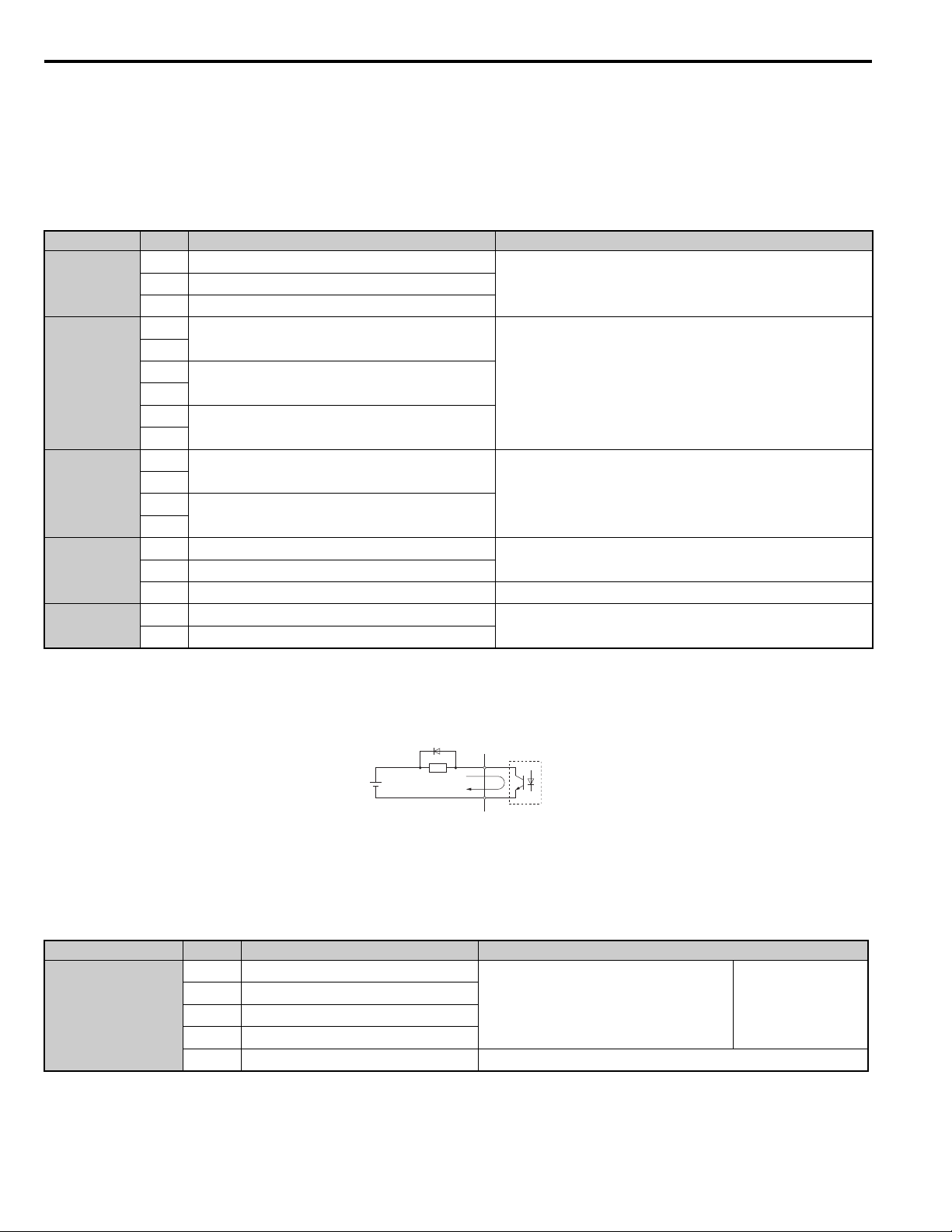
3 Electrical Installation
A
B
C
D
YEA_common
Output Terminals
Tab le 1 2 lists the output terminals on the drive. Text in parenthesis indicates the default setting for each multi-function
output.
Note: Multi-function relay output terminals are rated at a minimum of 10 mA. If less than 10 mA is required, use the photocoupler
outputs (P1-C1, P2-C2). Using the wrong current output level may cause the output to malfunction when the terminal is activated.
Table 12 Control Circuit Output Terminals
Type
Fault Relay
Multi-Function
Relay Output
<1>
Multi-Function
Photocoupler
Output
Monitor Output
Safety Monitor
Output
No. Terminal Name (Function) Function (Signal Level) Default Setting
N.O.
MA
N.C. output
MB
Fault output common
MC
M1
Multi-function relay output 1 (Brake release
command)
M2
M3
Multi-function relay output 2 (Output contactor close
command)
M4
M5
Multi-function relay output 3 (Drive ready)
M6
P1
Photocoupler output 1 (During Frequency output)
C1
P2
Photocoupler output 2 (Not Used/Through Mode)
C2
Analog monitor output 1 (Output speed)
FM
Analog monitor output 2 (Output current)
AM
Monitor common 0 V
AC
Safety monitor output
DM+
Safety monitor output common
DM-
30 Vdc, 10 mA to 1 A; 250 Vac, 10 mA to 1 A
Minimum load: 5 Vdc, 10 mA
Contact relay output
30 Vdc, 10 mA to 1 A
250 Vac, 10 mA to 1 A
Minimum load: 5 Vdc, 10 mA
48 Vdc, 2 to 50 mA <2>
-10 to +10 Vdc or 0 to +10 Vdc
Outputs status of Safe Disable function. Closed when both Safe
Disable channels are closed. Up to +48 Vdc 50 mA
<1> Refrain from assigning functions to terminals M1 thru M6 that involve frequent switching, as doing so may shorten relay performance life.
Switching life is estimated at 200,000 times (assumes 1 A, resistive load).
<2> Connect a suppression diode as shown in Figure 24 when driving a reactive load such as a relay coil. Make sure the diode rating is greater than
the circuit voltage.
Figure 24
A – External power, 48 V max. C – Coil
B – Suppression diode D – 50 mA or less
Figure 24 Connecting a Suppression Diode
Serial Communication Terminals
Table 13 Control Circuit Terminals: Serial Communications
Typ e
MEMOBUS/Modbus
Communication
<1>
<1> Enable the termination resistor in the last drive in a MEMOBUS network by setting DIP switch S2 to the ON position.
44 YAS KA WA TOEPYAIL1E01A YASKAWA AC Drive L1000E Quick Start Guide
No. Signal Name Function (Signal Level)
Communications input (+)
R+
Communications input (-)
R-
Communications output (+)
S+
Communications output (-)
S-
Shield ground 0 V
IG
MEMOBUS/Modbus communication: Use
an RS-485 or RS-422 cable to connect the
drive.
RS-485/422
MEMOBUS/Modbus
communication
protocol
115.2 kbps (max.)
Page 45

Electrical Installation
3
■ Terminal Configuration
E(G) HC H1 H2
DM+ DM-
IG R+ R- S+ S-
S1 S2 S3 S4 S5 S6 S7 S8 SN SC SP
V+ AC V- A1A2FM AM AC P1 C1 C2P2
M3 M4 M6
MA MB MC
M1 M2 M5
YEA_common
Control circuit terminals are arranged as shown in Figure 25.
Figure 25
3 Electrical Installation
Figure 25 Control Circuit Terminal Arrangement
Wire Size and Torque Specifications
WARNING! Fire hazard. Tighten all terminal screws to the specified tightening torque. Loose electrical connections could result in
death or serious injury by fire due to overheating of electrical connections. Improperly tightened terminal screws can also cause
erroneous equipment operation.
Select appropriate wire type and gauges from Table 14. For simpler and more reliable wiring, use crimp ferrules on the
wire ends. Refer to Tab le 1 5 for ferrule terminal types and sizes.
Table 14 Wire Gauges and Torque Specifications
Bare Wire Terminal Ferrule-Type Terminal
Applicable
Wire Size
mm2 (AWG)
Recomm.
mm2 (AWG)
Applicable
Wire Size
mm2 (AWG)
Recomm.
mm2 (AWG)
Standard wire:
0.25 to 1.0
(24 to 17)
Solid wire:
0.75
(18)
0.25 to 0.5
(24 to 20)
0.5
(20)
0.25 to 1.5
(24 to 16)
Wire Type
Shielded wire,
etc.
Terminal
Block
TB1, TB2,
TB4, TB5,
TB6
Terminal Size
FM, AC, AM, P1,
P2, PC, SC, A1,
A2, A3, +V, -V,
S1-S8, MA, MB,
MC, M1, M2, HC,
H1, H2, DM+,
DM-, IG, R+, R-,
S+, S-, RP, MP, E
(G)
M2
Tightening
Torq ue
Nm
(lb.in.)
0.22 to 0.25
(1.9 to 2.2)
YAS KA WA TOEPYAIL1E01A YASKAWA AC Drive L1000E Quick Start Guide 45
Page 46

3 Electrical Installation
d1
d2
6 mm
(0.24 in.)
L
YEA_common
Ferrule-Type Wire Terminals
Yaskawa recommends using CRIMPFOX 6, a crimping tool manufactured by PHOENIX CONTACT, to prepare wire
ends with insulated sleeves before connecting to the drive. Refer to Tab le 1 5 for dimensions.
Figure 26
Figure 26 Ferrule Dimensions
Table 15 Ferrule Terminal Types and Sizes
Size mm2 (AWG) Type Lmm (in) d1 mm (in) d2 mm (in) Manufacturer
0.25 (24) AI 0.25-6YE 10.5 (0.41) 0.8 (0.03) 2 (0.08)
PHOENIX CONTACT0.34 (22) AI 0.34-6TQ 10.5 (0.41) 0.8 (0.03) 2 (0.08)
0.5 (20) AI 0.5-6WH 14 (0.55) 1.1 (0.04) 2.5 (0.10)
■ Wiring the Control Circuit Terminal
This section describes the proper procedures and preparations for wiring the control terminals.
WARNING! Sudden Movement Hazard. Operating a drive with untested emergency circuits could result in death or serious injury.
Verify all drive fast stop circuit wiring and any additional emergency circuits before operating the drive.
WARNING! Fire hazard. Tighten all terminal screws to the specified tightening torque. Loose electrical connections could result in
death or serious injury by fire due to overheating of electrical connections.
WARNING! Electrical Shock Hazard. Do not remove covers or touch the circuit boards while the power is on. Failure to comply could
result in death or serious injury.
WARNING! Electrical Shock Hazard. Before servicing, disconnect all power to the equipment and lock out the power source. Failure to
comply may result in injury from electrical shock. Wait at least five minutes after all indicators are OFF and measure the DC bus voltage
level and main circuit terminals to confirm the circuit is safe before wiring.
WARNING! Sudden Movement and Hazard. Install additional emergency circuits separately from the drive fast stop circuits. Failure to
comply may result in personal injury.
NOTICE: Equipment Hazard. Do not connect control circuit ground terminals to the drive enclosure. Improper drive grounding can
cause control circuit malfunction.
NOTICE: Equipment Hazard. Insulate shields with heat shrink tubing or tape to prevent contact with other signal lines and equipment.
Improper wiring practices could result in drive or equipment malfunction due to short circuit.
NOTICE: Equipment Hazard. Use twisted-pair or shielded twisted-pair cables for control circuits. Improper wiring practices could result
in drive or equipment malfunction or nuisance trips.
NOTICE: Connect the shield of shielded cable to the appropriate ground terminal. Improper equipment grounding could result in drive
or equipment malfunction or nuisance trips.
NOTICE: Separate wiring for output terminals MA, MB, MC, M1 and M2 from wiring to other control circuit lines. Improper wiring
practices could result in drive or equipment malfunction or nuisance trips.
NOTICE: Separate control circuit wiring from main circuit wiring (terminals R/L1, S/L2, T/L3, B1, B2, U/T1, V/T2, W/T3, -, +1, +2) and
other high-power lines. Improper wiring practices could result in drive malfunction due to electrical interference.
NOTICE: Use a class 2 power supply (UL standard) when connecting to the control terminals. Improper application of peripheral
devices could result in drive performance degradation due to improper power supply.
NOTICE: Do not exceed 50 meters (164 feet) for the control line between the drive and the operator when using an analog signal from
a remote source to supply the frequency reference. Failure to comply could result in poor system performance.
NOTICE: Do not use unshielded cable for control wiring. Failure to comply may cause electrical interference resulting in poor system
performance. Use shielded, twisted-pair wires, and ground the shield to the ground terminal of the drive.
NOTICE: Insulate shields with tape or shrink tubing to prevent contact with other signal lines and equipment. Improper wiring practices
could result in drive or equipment malfunction due to short circuit.
46 YAS KA WA TOEPYAIL1E01A YASKAWA AC Drive L1000E Quick Start Guide
Page 47

3 Electrical Installation
Electrical Installation
3
A
B
C
D
Preparing wire
terminal ends
YEA_common
A
Wire the control circuit only after terminals have been properly grounded and main circuit wiring is complete. Refer to
Figure 27 for details. Prepare the ends of the control circuit wiring as shown in Figure 28. Refer to Wire Size and Torque
Specifications on page 45.
WARNING! Do not tighten screws beyond the specified tightening torque. Failure to comply may result in erroneous operation, damage
the terminal block, or cause injury due to fire from overheating of loose electrical connections.
NOTICE: Use shielded twisted-pair cables as indicated to prevent operating faults. Improper wiring practices could result in drive or
equipment malfunction due to electrical interference.
Connect control wires as shown in Figure 27.
Figure 27
A – Loosen screw to insert wire C – Avoid fraying wire strands when stripping
insulation from wire. Strip length 5.5 mm (0.22 in.)
B – Single wire or stranded wire D – Blade depth of 0.4 mm (0.02 in.) or less
Blade width of 2.5 mm (0.10 in.) or less
Figure 27 Terminal Board Wiring Guide
When connecting control wires to the terminals, use shielded twisted-pair wires (treating wire ends as shown in Figure 28
and connect the shield to the ground terminal (E [G]) of the drive.
Figure 28
E
B
D
A – Drive side D – Shield sheath (insulate with tape or heat-shrink tubing)
B – Insulation E – Shield
C – Control device side
Figure 28 Preparing the Ends of Shielded Cables
NOTICE: Do not exceed 50 meters (164 ft.) for the control line between the drive and the operator when using an analog signal from a
remote source to supply the frequency reference. Failure to comply could result in poor system performance.
C
YAS KA WA TOEPYAIL1E01A YASKAWA AC Drive L1000E Quick Start Guide 47
Page 48

3 Electrical Installation
YEA_
com-
■ Switches and Jumpers on the Terminal Board
The terminal board is equipped with several switches used to adapt the drive I/Os to the external control signals.
Figure 29 shows the location of these switches. Refer to Control I/O Configuration on page 49 for setting instructions.
Figure 29
Jumper S3
Terminal H1/H2
Sink/Source Sel.
DIP Switch S2
RS-422/485 Termination
Resistor
Off On
Figure 29 Locations of Jumpers and Switches on the Terminal Board
48 YAS KA WA TOEPYAIL1E01A YASKAWA AC Drive L1000E Quick Start Guide
Page 49

3 Electrical Installation
Electrical Installation
3
SC
S8
S7
24 Vdc
SP
SN
SC
S8
S7
24
Vdc
SP
SN
External
24
Vdc
SC
S8
S7
24 Vdc
SP
SN
◆ Control I/O Configuration
■ Setting Sink/Source with Input Terminals SN and SP
Use the wire jumper between terminals SC and SP or SC and SN to select between Sink mode, Source mode or external
power supply for the digital inputs S1 to S8 as shown in Tab le 1 6 (Default: Sink mode, internal power supply).
NOTICE: Damage to Equipment. Do not short terminals SP and SN. Failure to comply will damage the drive.
Table 16 Digital Input Sink / Source / External Power Supply Selection
Sinking Mode (NPN)
Sourcing Mode (PNP)
Drive Internal Power Supply
(Terminal SN and SP)
External 24 Vdc Power Supply
S7
S8
SN
SC
External
24 Vdc
SP
24 Vdc
YAS KA WA TOEPYAIL1E01A YASKAWA AC Drive L1000E Quick Start Guide 49
Page 50

3 Electrical Installation
24 Vdc
H1
H2
HC
Jumper S3
24 Vdc
H1
H2
HC
External
24 Vdc
Jumper S3
24 Vdc
H1
H2
HC
External
24 Vdc
Jumper S3
YE
■ Sinking/Sourcing Mode Selection for Safe Disable Inputs
Use jumper S3 on the terminal board to select between Sink mode, Source mode or external power supply for the Safe
Disable inputs H1 and H2 as shown in Ta ble 17 (Default: Sink mode, internal power supply).
Table 17 Safe Disable Input Sink / Source / External Power Supply Selection
Drive Internal Power Supply External 24 Vdc Power Supply
Sinking Mode
Jumper S3
HC
24 Vdc
Sourcing Mode
H1
H2
◆ Connect to a PC
This drive is equipped with a USB port (type-B).
The drive can connect to a USB port on a PC using a USB 2.0, AB-type cable (sold separately). After connecting the
drive to a PC, Yaskawa DriveWizard Plus software can be used to monitor drive performance and manage parameter
settings. Contact Yaskawa for more information on DriveWizard Plus.
Download and install the USB driver before connecting L1000 to a PC with the USB cable.
To obtain the driver and software of USB Copy Unit, CopyUnitManager and DriveWizardPlus, access these sites:
U.S.A: http://www.yaskawa.com
Other areas: contact a Yaskawa representative.
Figure 30
USB Cable
(Type-AB)
(Type-B) (Type-A)
PC
Figure 30 Connecting to a PC (USB)
50 YAS KA WA TOEPYAIL1E01A YASKAWA AC Drive L1000E Quick Start Guide
Page 51

Electrical Installation
3
◆ Wiring Checklist
No. Item Page
1 Check drive model number to ensure receipt of correct model. –
Make sure you have the correct braking resistors, DC link choke, noise filters, and other peripheral devices
2
installed.
3 Check the option card model number. –
4 Ensure that the area surrounding the drive complies with specifications. 17
5 The voltage from the power supply should be within the input voltage specification range of the drive. –
6 The voltage rating for the motor should match the drive output specifications.
7 Verify that the drive is properly sized to run the motor.
8 Confirm proper branch circuit protection as specified by national and local codes. 23
9 Properly wire the power supply to drive terminals R/L1, S/L2, and T/L3. 26
Properly wire the drive and motor together.
10
The motor lines and drive output terminals R/T1, V/T2, and W/T3 should match in order to produce the
desired phase order. If the phase order is incorrect, the drive will rotate in the opposite direction.
11 Use 600 Vac vinyl-sheathed wire for the power supply and motor lines. 33
Use the correct wire gauges for the main circuit. Refer to Wire Gauges and Tightening Torque on page 33. 33
• Consider the amount of voltage drop when selecting wire gauges. Increase the wire gauge when the voltage
drop is greater than 2% of motor rated voltage. Ensure the wire gauge is suitable for the terminal block. Use
12
13 Properly ground the drive. Review page 41. 41
14
15
16
17 Use twisted-pair line for all drive control circuit wiring. 42
18 Connect the shields of shielded wiring to the ground terminal (E [G]). 46
19 Properly wire any option cards. 45
20
21
22 Pick up all wire clippings. –
23 Ensure that no frayed wires on the terminal block are touching other terminals or connections. –
24 Properly separate control circuit wiring and main circuit wiring. –
25 Analog signal line wiring should not exceed 50 m (164 ft.). –
26 Safe Disable input wiring should not exceed 30 m (98 ft.). –
the following formula to calculate the amount of voltage drop:
Line drop voltage (V) = 3 × wire resistance (Ω/km) × wire length (m) × current (A) × 10
• If the cable between the drive and motor exceeds 50 m (164 feet), adjust the carrier frequency set to C6-02
accordingly.
Tightly fasten all terminal screws (control circuit terminals, grounding terminals).
Refer to Wire Gauges and Tightening Torque on page 33.
Install a magnetic contactor when using a dynamic braking option. Properly install the resistor and ensure that
overload protection shuts off the power supply using the magnetic contactor.
Verify phase advancing capacitors, input noise filters, or ground fault circuit interrupters are NOT installed on
the output side of the drive.
Check for any other wiring mistakes.
Only use a multimeter to check wiring.
Properly fasten the control circuit terminal screws in the drive.
Refer to Wire Gauges and Tightening Torque on page 33.
3 Electrical Installation
Drive, peripherals, option cards
–
Installation area and physical setup
Power supply voltage, output voltage
15
205
15
205
Main circuit wiring
40
33
-3
41
33
–
–
Control circuit wiring
–
33
YAS KA WA TOEPYAIL1E01A YASKAWA AC Drive L1000E Quick Start Guide 51
Page 52

4 Start-Up Programming
RUN DS1 DS2 POWER
RUN DS1 DS2 POWER
4 Start-Up Programming
LED Monitor JVOP-184 shows information about drive status including faults and alarms. The optional digital operator
JVOP-180, can be used to adjust parameters as required.
◆ LED Monitor JVOP-184
The LED monitor indicates operation status by combinations of the LEDs (LIGHT/BLINK/OFF) at RUN, DS1, and DS2.
Figure 31
G
F
E
RUN DS1 DS2
RUN DS1 DS2 STATUS
READY
RUN
ALARM(RUN)
PGOH,LT
BB,HBB
EF,SE
OV,UV
OH,OL
OC,GF,SC,PGO
CPF,OFA,OFB,OFC
Other Fault
:LIGHT :BLINK :LIGHT OFF
PWRLED MONITOR JVOP-184
A
B
C
D
A – PWR LED (Red) E – DS2 LED (Green)
B – Drive Status Indications F – DS1 LED (Green)
C – Alarm Indications G – RUN LED (Green)
D – Fault Indications
Figure 31 LED Monitor Component Names
■ LED Display Examples
Normal Operation
Figure 32 shows the LED display when the drive is ready and no FWD/REV signal is active.
Figure 32
Figure 32 Normal Operation LED
Alarm
Figure 33 shows the LED display when a minor fault occurs. Refer to Troubleshooting on page 130 and take appropriate
countermeasures.
Figure 33
Figure 33 Alarm LED
Fault
Figure 34 shows the LED display when an oV or UV fault has occurred.
Figure 34
RUN DS1 DS2 POWER
Figure 34 Fault LED
52 YASKAWA TOEPYAIL1E01A YASKAWA AC Drive L1000E Quick Start Guide
Page 53

4 Start-Up Programming
Start-Up Programming
4
YEA_com
F1
F2
RESET
RUN
ENTER
LO
RE
LO
RE
◆ Digital Operator JVOP-180 Keys and Displays
Use the digital operator to enter Run and Stop commands, edit parameters, and display data including fault and alarm
information.
Keys and Displays
■
Figure 35
DIGITAL OPERATOR JVOP-180
ALM
12
1
11
9
8
10
F2F1
2
ESC
3
RUN STOP
LO
RE
ENTERRESET
4567
Figure 35 Keys and Displays on the Digital Operator
No. Display Name Function
1
2ESC Key
ESC
Function Key
(F1, F2)
The functions assigned to F1 and F2 vary depending on the currently displayed menu.
The name of each function appears in the lower half of the display window.
• Returns to the previous display.
• Moves the cursor one space to the left.
• Pressing and holding this button will return to the Speed Reference display.
3RESET Key
• Moves the cursor to the right.
• Resets the drive to clear a fault situation.
Starts the drive in the LOCAL mode.
The Run LED
4 RUN Key
• is on, when the drive is operating the motor.
• flashes during deceleration to stop or when the speed reference is 0.
• flashes quickly, the drive is disabled by a DI, the drive was stopped using a fast stop
DI, or an Up/Down command was active during power up.
5 Up Arrow Key
6 Down Arrow Key
Scrolls up to display the next item, select parameter numbers, and increment setting
values.
Scrolls down to display the previous item, select parameter numbers, and decrements
setting values.
7STOP Key
STOP
8 ENTER Key
<1> Stops drive operation.
• Enters parameter values and settings.
• Selects a menu item to move between displays.
Switches drive control between the operator (LOCAL) and the control circuit
9 LO/RE Selection Key <2>
terminals (REMOTE) for the Run command and speed reference. The LED is on
when the drive is in the LOCAL mode (operation from keypad).
10 RUN Light Lit while the drive is operating the motor. Refer to page 56 for details.
11 LO/RE Light
12 ALM LED Light Refer to ALARM (ALM) LED Displays on page 56.
RUN
Lit while the operator is selected to run the drive (LOCAL mode). Refer to page 56
for details.
YAS KA WA TOEPYAIL1E01A YASKAWA AC Drive L1000E Quick Start Guide 53
Page 54

4 Start-Up Programming
YEA_comm
F1
F1
F1
F1
<1> The STOP key has highest priority. Pressing the STOP key will always cause the drive to stop the motor, even if an Up/Down command is
active at any external Up/Down command source. To disable the STOP key priority, set parameter o2-02 to 0.
<2> The LO/RE key can only switch between LOCAL and REMOTE when the drive is stopped. By default settings the LO/RE key function is
disabled. To allow using the LO/RE key for switching between LOCAL and REMOTE, set parameter o2-01 to 1.
■ LCD Display
Figure 36
123
- MODE Speed Ref (OPR)
DRV
Rdy
4
5
U1-01= 0.00%
U1-02= 0.00%
U1-03= 0.00A
FWD
Figure 36 LCD Display
Table 18 Display and Contents
No. Name Display Content
MODE Displayed when in Mode Selection.
MONITR Displayed when in Monitor Mode.
1 Operation Mode Menus
2Mode Display Area
3 Ready Rdy Indicates the drive is ready to run.
4 Data Display – Displays specific data and operation data.
Speed Reference Source
5
6
Assignment
LO/RE
Display
<1>
<2>
VERIFY Indicates the Verify Menu.
PRMSET Displayed when in Parameter Setting Mode.
A.TUNE Displayed during Auto-Tuning.
SETUP Displayed when in Setup Mode.
DRV Displayed when in Drive Mode.
PRG Displayed when in Programming Mode.
OPR Displayed when the speed reference source is assigned to the LCD Operator.
COM
OP Displayed when the speed reference is assigned to an option card.
RSEQ Displayed when the Up/Down command is supplied from a remote source.
LSEQ Displayed when the Up/Down command is supplied from the operator keypad.
RREF Displayed when the speed reference is supplied from a remote source.
LREF Displayed when the speed reference is supplied from the operator keypad.
HELP
Displayed when the speed reference source is assigned to MEMOBUS/Modbus
Communication.
Pressing displays the Help menu.
RSEQ
LREF
FWD/REV
789
6
7
8FWD/REV
54 YAS KA WA TOEPYAIL1E01A YASKAWA AC Drive L1000E Quick Start Guide
Function Key 1
(F1)
←
HOME
ESC
FWD During Up command
REV During Down command
Pressing scrolls the cursor to the left.
Pressing returns to the top menu (Speed Reference).
Pressing returns to the previous display.
Page 55

Start-Up Programming
4
No. Name Display Content
F1
F1
F1
F1
DIGITAL OPERATOR JVOP-180
ALM
- MODE -
U1-01= 0.00%
U1-02= 0.00%
U1-03= 0.00A
DRV
Speed Ref (OPR)
Rdy
FWD
RSEQ
LREF
YEA_
com-
YEA_
com-
4 Start-Up Programming
FWD/REV
Pressing switches between Up and Down when the Up/Down command is set from
the digital operator.
9
Function Key 2
(F2)
DATA
→
RESET
Pressing scrolls to the next display.
Pressing scrolls the cursor to the right.
Pressing resets the existing drive fault or error.
<1> Displayed when in Drive Mode.
<2> Displayed when in Drive Mode and Monitor Mode.
■ Powering Up the Drive and Operation Status Display
Powering Up the Drive
Perform the following power-off checks before applying main power to the drive.
WARNING! Electrical Shock Hazard. Do not contact live electrical parts. Failure to comply could result in death or serious injury. Never
touch the output terminals directly with your hands or allow the output lines to come into contact with the drive case.
WARNING! Sudden Movement Hazard. Operating a drive with untested emergency circuits could result in death or serious injury.
Always check the operation of drive fast stop circuits and any additional emergency circuits after they are wired. Fast stop circuits are
required to provide safe and quick shutdown of the drive.
WARNING! Sudden Movement Hazard. Ensure start/stop and safety circuits are wired properly and in the correct state before
energizing the drive. Failure to comply could result in death or serious injury from moving equipment.
Power-off Checks Description
Ensure the power supply voltage is correct on the supply side of the disconnect, before applying power to the
drive.
200 V class: 3-phase 200 to 240 Vac 50/60 Hz
Power supply voltage
Drive output terminals and
motor terminals
Control circuit terminals
Drive control terminal status Open all control circuits to the drive I/O terminal block.
400 V class: 3-phase 380 to 480 Vac 50/60 Hz
Properly wire the power supply input terminals (R/L1, S/L2, T/L3). Check for correct wiring, terminals are
tightened, and there are no loose wire strands.
Check for proper grounding of drive and motor.
Properly wire drive output terminals U/T1, V/T2, and W/T3 with motor terminals U/T1, V/T2, and W/T3.
Check for correct wiring, terminals are tightened, and there are no loose wire strands.
Check control circuit terminal connections. Check that control circuit terminals are correctly wired, terminals
are tightened, and there are no loose wire strands.
Status Display
When the power supply to the drive is turned on, the digital operator lights will appear as follows:
No. Name Description
Normal
Operation
DIGITAL OPERATOR JVOP-180
- MODE -
Fault
DRV
EF3
Ext Fault S3
FWD
ALM
RESET
External fault (example)
YAS KA WA TOEPYAIL1E01A YASKAWA AC Drive L1000E Quick Start Guide 55
The data display area in the upper half of the display, displays the speed reference. DRV
is displayed.
Data displayed varies by the type of fault. Refer to Fault Displays, Causes, and
Possible Solutions on page 130 for more information and possible solutions. ALM
LED is lit and DRV displayed.
Page 56

4 Start-Up Programming
common_
TM
■ ALARM (ALM) LED Displays
Table 19 ALARM (ALM) LED Status and Contents
State Content Display
Illuminated When the drive detects an alarm or error.
• When an alarm occurs.
Flashing
Off Normal operation (no fault or alarm).
• When oPE is detected.
• When a fault or error occurs during Auto-Tuning.
■ LO/RE LED and RUN LED Indications
Table 20 LO/RE LED and RUN LED Indications
LED Lit Flashing Flashing Quickly <1>
When source of the Up/
Down command is assigned
to the digital operator
––
(LOCAL).
• While the drive is set for
LOCAL, an Up/Down
command was entered to the
input terminals after which
the drive was then switched
to REMOTE.
• An Up/Down command was
entered via the input
terminals while not in the
Drive Mode.
• During deceleration when a
Fast Stop command was
During run
• During deceleration to stop.
• When an Up/Down command
is input and speed reference is
0%.
entered.
• The drive output is shut off
by the Safe Disable
function.
• While the drive was running
in the REMOTE mode, the
STOP key was pushed.
Examples
Off
Up/Down command to be given
from a device other than the digital
operator (REMOTE).
During stop
<1> Refer to Figure 37 for the difference between “flashing” and “flashing quickly”.
Figure 37
1 s
Flashing
Flashing
quickly
ON
ON ON
ON
ON ON
Figure 37 RUN LED Status and Meaning
56 YAS KA WA TOEPYAIL1E01A YASKAWA AC Drive L1000E Quick Start Guide
Page 57

Start-Up Programming
4
Figure 38
Drive output speed
during stop
Speed setting
OFF
ON
Flashing
OFF
OFF
RUN LED
RUN
0%
10%
RUN
STOP
STOP
Up/Down
common_
TM
YEA_comm
Figure 38 RUN LED and Drive Operation
■ Menu Structure for Digital Operator
Figure 39
4 Start-Up Programming
- MODE -
U1-01= 0.00%
U1-02= 0.00%
U1-03= 0.00A
- MODE -
U1-01= 0.00%
U1-02= 0.00%
U1-03= 0.00A
- MODE - PRG
HELP
- MODE - PRG
HELP
- MODE - PRG
DRV
Speed Ref (OPR)
FWD
DRV
Monitor Menu
FWD
Modified Consts
Modified
X Parameters
FWD
DATA
Quick Setting
FWD
DATA
Programming
Rdy
RSEQ
LREF
Rdy
RSEQ
LREF
<4>
Rdy
-MONITR-
U1-01= 000.00%
-MONITR-
U
U1-02= 0.00%
U1-03= 0.00A
-MONITR-
U
U2-02= oPr
U2-03= 0.00Hz
DRV
Speed Ref 1
㸦0.00㹼50.00㸧
0.00%
FWD
←→
DRV
Monitor
1 -01= 0.00%
FWD
DRV
Fault Trace
2 -01= oC
FWD
Rdy
RSEQ
LREF
Rdy
RSEQ
LREF
<3>
-MONITR-
U1-
U1-02= 0.00%
U1-03= 0.00A
-MONITR-
U1-
U1-03= 0.00A
U1-04= 0
DRV
Speed Reference
01 = 0.00%
FWD
DRV
Output Speed
02 = 0.00%
FWD
Rdy
RSEQ
LREF
Rdy
RSEQ
LREF
Initial Display <5>
L1000E
L1000E
YAS K A WA
XXXVX.X/X.XkW
XX.XX/XX.XXA
<XXXXXXXXX>
<6>
Programming Mode <2> Drive Mode <1>
FWD
HELP
- MODE - PRG Rdy
Auto-Tuning
HELP
AUTO
FWD
DATA
DATA
Figure 39 Digital Operator Menu and Screen Structure
<1> Pressing will start the motor.
RUN
<2> Drive cannot operate the motor.
<3> Flashing characters are shown as .
0
<4> An "X" character is used as a placeholder for illustration purposes in this manual. The LCD Operator will
display the actual setting values.
<5> The Speed Reference appears after the initial display which shows the product name.
<6> The information that appears on the display will vary depending on the drive.
YAS KA WA TOEPYAIL1E01A YASKAWA AC Drive L1000E Quick Start Guide 57
Page 58

4 Start-Up Programming
- MODE -
U1-01= 0.00%
U1-02= 0.00%
U1-03= 0.00A
DRV
Speed Ref (OPR)
Rdy
RSEQ
LREF
FWD FWD/REV
←→
-PRMSETInitialization
Select Language
PRG
FWD
A1-00=0
←→
-PRMSETAccel/Decel
Accel Ramp 1
PRG
FWD
C1-01= 1.50 sec
φψ
-PRMSET-
C1-02= 1.50 sec
(0.0~600.00)
“1.50 sec”
PRG
Decel Ramp 1
FWD
-PRMSET-
C1-02= 001.50 sec
(0.0~600.00)
“1.50 sec”
PRG
Decel Ramp 1
←→
FWD
F1
-PRMSET-
C1-02=001.50 sec
(0.0~600.00)
“1.50 sec”
PRG
Decel Ramp 1
←→
FWD
◆ The Drive and Programming Modes
The drive has a Drive Mode to operate the motor and a Programming Mode to edit parameter settings.
Drive Mode: In Drive Mode the user can operate the motor and observe U Monitor parameters. Parameter settings cannot
be edited or changed when in Drive Mode.
Programming Mode: In Programming Mode the user can edit and verify parameter settings and perform Auto-Tuning.
The drive will not accept an Up/down command when the digital operator is in the Programming Mode unless parameter
b1-08 is set to 1 to allow an Up/down command.
Changing Parameter Settings or Values
■
This example explains changing C1-02 (Deceleration Ramp 1) from 1.50 seconds (default) to 2.50 seconds.
Step Display/Result
1. Turn on the power to the drive. The initial display appears.
- MODE - PRG
2.
Press or until the Parameter Setting Mode screen appears.
Programming
HELP
FWD
DATA
3.
Press to enter the parameter menu tree.
4.
Press or to select the C parameter group.
5.
Press two times.
6.
Press or to select the parameter C1-02.
7.
Press to view the current setting value (1.5 s). The left most digit flashes.
8. Press , or until the desired number is selected. “1” flashes.
F2
right
-PRMSET-
C1-01 = 1.50 sec
PRG
Basic Setup
Accel Ramp 1
FWD
←→
-PRMSET-
C1-01= 1.50 sec
←→
PRG
Accel Ramp 1
(0.0~600.00)
“1.50 sec”
FWD
-PRMSET-
9.
Press and enter 0020.0.
C1-02=002.50 sec
←→
58 YAS KA WA TOEPYAIL1E01A YASKAWA AC Drive L1000E Quick Start Guide
PRG
Decel Ramp 1
(0.0~600.00)
“1.50 sec”
FWD
Page 59

Start-Up Programming
4
Step Display/Result
Entry Accepted
φψ
-PRMSET-
C1-02= 2.50 sec
(0.0~600.00)
“1.50 sec”
PRG
Decel Ramp 1
FWD
10.
Press to confirm the change.
11. The display automatically returns to the screen shown in Step 4.
12.
Press as many times as necessary to return to the initial display.
4 Start-Up Programming
- MODE -
DRV
Speed Ref (OPR)
U1-01= 0.00%
U1-02= 0.00%
U1-03= 0.00A
FWD FWD/REV
Rdy
RSEQ
LREF
YAS KA WA TOEPYAIL1E01A YASKAWA AC Drive L1000E Quick Start Guide 59
Page 60

4 Start-Up Programming
←
→
←
→
- MODE -
U1-01= 0.00%
U1-02= 0.00%
U1-03= 0.00A
DRV
Speed Ref (OPR)
Rdy
RSEQ
LREF
Control Circuit
Terminal
Operator
<1>
<2>
<2>
Speed reference
appears when
powered up
HELP
- MODE - PRG
Quick Setting
DATA
FWD
Entry Accepted
- SETUP -
b1-01= 0
∗0∗
Operator
PRG
Speed Ref Sel
Rdy
Home FWD DATA
- SETUP -
A1-02= 2
∗2∗
Open Loop Vector
PRG
Control Method
Rdy
Home FWD DATA
- SETUP -
b1-02= 1
∗1∗
Digital Inputs
PRG
Up/Dn Command Sel
Rdy
Home FWD DATA
- SETUP -
L3-01= 1
∗1∗
General Purpose
PRG
StallP Accel Sel
Rdy
Home FWD DATA
“1”
- SETUP -
b1-01= 0
∗0∗
Operator
PRG
Speed Ref Sel
Rdy
FWD
“1”
- SETUP -
b1-01= 0
∗0∗
Analog Input
PRG
Speed Ref Sel
Rdy
FWD
FWD FWD/REV
YEA_commo
■ Simplified Setup Using the Setup Group
In the Setup Group, the drive lists the basic parameters needed to set up the drive for an elevator application. This group
expedites the startup process for an elevator application by showing only the most important parameters for the
application.
Using the Setup Group
Figure 40 illustrates how to enter and how to change parameters in the Setup Group.
The first display shown when entering the Setup Group is the Control Method menu. Skipping this display will keep the
current Setup Group parameter selection. The default setting for the Setup Group is a group of parameters most
commonly use in control methods.
In this example, the Setup Group is accessed to change b1-01 from 0 to 1. This changes the source of the speed reference
from the digital operator to the control circuit terminals.
<1> Use the up and down arrow keys to scroll through the Setup Group. Press the ENTER key to view or change parameter settings.
<2> To return to the previous menu without saving changes, press the ESC key.
60 YAS KA WA TOEPYAIL1E01A YASKAWA AC Drive L1000E Quick Start Guide
Figure 40 Setup Group Example
Page 61

4 Start-Up Programming
Start-Up Programming
4
- MODE -
U1-01= 0.00%
U1-02= 0.00%
U1-03= 0.00A
DRV
Speed Ref(A1/A2)
Rdy
RSEQ
RREF
FWD FWD/REV
YEA_
com-
LO
RE
F2F1
ESC
RUN STOP
ENTERRESET
ALM
DIGITAL OPERATOR JVOP-180
- MODE -
U1-01= 0.00%
U1-02= 0.00%
U1-03= 0.00A
DRV
Speed Ref (OPR)
Rdy
LSEQ
LREF
FWD
YEA
_co
mm
■ Switching Between LOCAL and REMOTE
LOCAL mode is when the drive is set to accept the Up/Down command from the digital operator keypad. REMOTE
mode is when the drive is set to accept the Up/Down command from an external device (via the input terminals or serial
communications, etc.).
Switch the operation between LOCAL and REMOTE using the LO/RE key on the digital operator or via a digital input.
This key is disabled with default settings, but can be enabled by setting parameter o2-01 to 1.
Note: 1. After selecting LOCAL, the LO/RE light will remain lit.
2. The drive will not allow the user to switch between LOCAL and REMOTE during run.
Using the LO/RE Key on the Digital Operator
Step Display/Result
1. Turn on the power to the drive. The initial display appears.
Press . The LO/RE light will light up. The drive is now in LOCAL.
2.
To set the drive for REMOTE operation, press again.
◆ Start-Up Flowcharts
This section covers basic setup for the drive, including Auto-Tuning procedures and corresponding flowcharts. Follow the
flowchart that matches the motor used in your application. Refer to Types of Auto-Tuning on page 68
types of Auto-Tuning.
Flowchart Purpose Page
A Installation, wiring, and basic steps required to setup the motor and elevator for operation 62
B Auto-Tuning for induction motors 65
C Auto-Tuning for PM motors 66
D Encoder Offset Auto-Tuning 67
for details on the
YAS KA WA TOEPYAIL1E01A YASKAWA AC Drive L1000E Quick Start Guide 61
Page 62

4 Start-Up Programming
For control modes below, refer to
• V/f Control
• Open Loop Vector Control
• Closed Loop Vector Control
For Closed Loop Vector for PM, refer to
START
Install the drive as explained in
Wire the drive as explained in
Check the PG encoder power supply selection.
(Closed Loop Vector Control only -CLV)
Apply main power to the drive.
Adhere to safety messages concerning application of power.
Perform Auto-Tuning for motor parameters and the PG encoder offset.
Determine the
source of the speed
reference.
Analog Input
Digital operator (b1-01 = 0)
(Speed selection by digital inputs)
Assign functions to the analog/digital I/O terminals using
parameters H1-, H2-, H3-, and H4-.
Set up:
• Acceleration/deceleration ramp (C1-)
• Jerk settings (C2-)
Perform a test run.
Fine-tuning
• Adjust settings for the brake sequence (S1-) .
• Adjust speed control loop (C5-) etc.
FINISH
Set up:
• Preset speed references (d1-)
• Acceleration/deceleration ramp (C1-)
• Jerk settings (C2-)
Assign functions to the digital I/O terminals using
parameters H1- and H2-.
Set the Speed Reference Selection mode
parameter d1-18.
Set the Unit Length in parameter o1-12.
Set up o1-20 to o1-22 and then select the display units for speed,
acceleration and deceleration ramp and jerk settings in o1-03.
Set up the Inspection Operation sequence.
Set up the PG encoder feedback in F1- parameters when using a
Closed Loop Vector Control and check the PG encoder rotation direction.
Select the control mode in parameter A1-02.
Check the motor rotation direction.
Flowchart B: Auto-Tuning for Induction Motors on page 65.
Flowchart C: Auto-Tuning for PM Motors on page 66.
Mechanical Installation on page 17.
Main Circuit Wiring on page 32.
■ Flowchart A: Installation, Wiring, Basic Setup for Motor and Elevator
The flowchart below covers the basic procedure required to install the drive, motor, and elevator.
Figure 40
Figure 41 Installation, Wiring, Basic Setup for Motor and Elevator
Note: Set parameter H5-11 to 1 when setting parameters using MEMOBUS/Modbus communications.
62 YAS KA WA TOEPYAIL1E01A YASKAWA AC Drive L1000E Quick Start Guide
Page 63

4 Start-Up Programming
Start-Up Programming
4
■ Power On
Take the following precautions before applying main power to the drive:
WARNING! Sudden Movement Hazard. Ensure start/stop, I/O and safety circuits are wired properly and in the correct state before
energizing or running the drive. Failure to comply could result in death or serious injury from moving equipment.
WARNING! Fire Hazard. Do not use an improper voltage source. Failure to comply could result in death or serious injury by fire. Verify
that the rated voltage of the drive matches the voltage of the incoming power supply before applying power.
WARNING! Fire Hazard. Loose electrical connections could result in death or serious injury by fire due to overheating of electrical
connections. Tighten all terminal screws to the specified tightening torque.
WARNING! Fire Hazard. Do not connect the AC power line to the output motor terminals of the drive. Failure to comply could result in
death or serious injury by fire as a result of drive damage from line voltage application to output terminals.
• Do not connect AC line power to output terminals U/T1, V/T2, and W/T3.
• Make sure that the power supply lines are connected to main circuit input terminals R/L1, S/L2, and T/L3
(or R/L1 and S/L2 for single-phase power).
WARNING! Sudden Movement Hazard. Clear personnel, secure equipment and check sequence and safety circuitry before starting
the drive. Failure to comply could result in death or serious injury from moving equipment.
• Clear all personnel from the drive, motor, and machine area.
• Secure covers, couplings, shaft keys, and machine loads.
• Ensure start/stop and safety circuits are wired properly and in the correct state.
WARNING! Sudden Movement Hazard. Operating a drive with untested emergency circuits could result in death or serious injury.
Always check the operation of drive fast stop circuits and any additional emergency circuits after they are wired. Fast stop circuits are
required to provide safe and quick shutdown of the drive.
NOTICE: Equipment Hazard. Comply with proper wiring practices. The motor may run in reverse if the phase order is backward.
Connect motor input terminals U/T1, V/T2, and W/T3 to drive output terminals U/T1,V/T2, and W/T3. The phase order for the drive and
motor should match.
NOTICE: Equipment Hazard. Check all the wiring including the PG encoder wiring and PG option jumper settings, to ensure that all
connections are correct after installing the drive and connecting any other devices. Failure to comply could result in damage to the
drive.
After applying the power, the drive mode display should appear and no fault or alarm should be displayed. In the event of
a drive fault or error code, refer to Troubleshooting on page 130.
Control Mode Selection
■
Select one of the four motor control modes after applying power to the drive. Note that Closed Loop Vector modes require
PG encoder feedback cards. The table below indicates possible control modes depending on the motor type and shows the
required encoder feedback card.
Machine Type Control Mode A1-02 setting Encoder Option Card
Induction motor without encoder
Induction motor with incremental encoder Closed Loop Vector Control 3 PG-B3 / PG-X3
Permanent magnet motor with EnDat 2.1/01,
EnDat 2.2/01, or EnDat 2.2/22 encoder
Permanent magnet motor with ERN1387 or
ERN487 encoder
Yaskawa IPM motor with incremental encoder Closed Loop Vector Control for PM motors 7 PG-X3
V/f Control 0 No card required
Open Loop Vector Control 2 No card required
Closed Loop Vector Control for PM motors 7 PG-F3
Closed Loop Vector Control for PM motors 7 PG-E3
YAS KA WA TOEPYAIL1E01A YASKAWA AC Drive L1000E Quick Start Guide 63
Page 64

4 Start-Up Programming
■ Motor Rotation Direction Setup
Check the direction of motor rotation to verify the Up command causes the elevator to move in the upward direction.
Perform the following checks to confirm proper motor and load direction:
• The drive outputs motor voltage in U/T1-V/T2-W/T3 phase sequence when an Up command is issued. Check the motor
rotation with this phase sequence (for most motors clockwise is seen from the shaft side).
• If the motor drives the elevator in the up direction with a U/T1-V/T2-W/T3 sequence, make sure parameter b1-14 is set
to 0.
• If the motor drives the elevator in the down direction with a U/T1-V/T2-W/T3 sequence, make sure parameter b1-14 is
set to 1. Motor direction may also be changed by reversing two motor leads connected to U/T1, V/T2, W/T3 on the
drive terminal block.
DANGER! Electrical Shock Hazard. Do not connect or disconnect wiring while the power is on. Failure to comply will result in death or
serious injury. Before servicing, disconnect all power to the equipment. The internal capacitor remains charged even after the power
supply is turned off. The charge indicator LED will extinguish when the DC bus voltage is below 50 Vdc. To prevent electric shock, wait
at least five minutes after all indicators are OFF and measure the DC bus voltage level to confirm safe level.
Note: Always perform motor rotation direction setup prior to setting the encoder rotation direction.
■ PG Encoder Setup
PG Encoder Resolution Setup
Set the encoder resolution (incremental signal in the case of absolute encoders with Sin/Cos channels) in parameter F1-
01.
PG Encoder Rotation Direction Setup
Perform the following steps to make sure the PG encoder rotation direction is set up correctly in the drive.
If information about the signal sequence of the PG encoder is available:
1. Check the sequence of PG encoder phases A and B when the motor drives the elevator in the up direction.
2. If the PG encoder A phase leads phase B, make sure F1-05 is set to 0.
3. If the PG encoder B phase leads phase A, make sure F1-05 is set to 1.
If no information about the signal sequence of the PG encoder is available:
1. Turn the motor manually in elevator up direction while checking the value of monitor U1-05.
2. If the value in U1-05 is positive, the set PG encoder direction is correct.
3. If the value in U1-05 is negative, alter the setting of parameter F1-05.
Note: Always set the motor rotation direction prior to the encoder rotation direction. Refer to Motor Rotation Direction Setup on
page 64.
64 YAS KA WA TOEPYAIL1E01A YASKAWA AC Drive L1000E Quick Start Guide
Page 65

4 Start-Up Programming
Start-Up Programming
4
START
Set terminals H1 and H2 if the Safe Disable function is used.
Enter the data in to T1- parameters as indicated on the
display.
Is the Control Mode
V/f Control ?
Apply the brake if it was released during Auto-tuning.
FINISH
Can the motor
rotate freely?
Select Stationary Auto-Tuning
for Terminal Resistance only,
T1-01 = 2.
Select Stationary
Auto-Tuning 1 or 2
T1-01 = 1 or 4.
No
A1-02=2 or 3
Yes
A1-02=0
No
Yes
(Ropes removed)
Select Rotational
Auto-Tuning
T1-01 = 0.
Press the Up key until “Tuning Ready” is displayed.
Enter the data in to T1- parameters as
indicated on the display.
Press the Up key until “Tuning Ready” is
displayed.
<1>
Release the Brake.
Close the motor contactor(s).
Press the Run key on the digital operator
and wait until Auto-Tuning is finished.
Set the Baseblock input (H1- = 8/9) if used.
Tuning
Successful?
Refer to
Remove the source of Fault/Alarm
and repeat Auto Tuning.
Open terminals H1-HC and H2-HC if used during the normal sequence.
Open the motor contactor(s).
Open the Baseblock input (H1- = 8/9) if used.
No
(Alarm or Fault code
displayed
Yes
(“Entry Accepted”
displayed) <2>
<1>
Auto-Tuning Fault Detection
on page 138.
YEA_comm
on
■ Flowchart B: Auto-Tuning for Induction Motors
The flowchart below covers Auto-Tuning for induction motors operating with V/f Control, Open Loop Vector Control, or
Closed Loop Vector Control.
<1> If an LED operator is used, the display shows “ ”.
<2> If an LED operator is used, the display shows “ ”.
Figure 42 Auto-Tuning for Induction Motors
YAS KA WA TOEPYAIL1E01A YASKAWA AC Drive L1000E Quick Start Guide 65
Page 66

4 Start-Up Programming
Refer to Flowchart D: PG Encoder Offset Auto-Tuning on page 67.
Auto-Tuning Fault Detection
on page 138.
YEA_comm
■ Flowchart C: Auto-Tuning for PM Motors
The flowchart below covers Auto-Tuning for permanent magnetic (PM) motors operating with Closed Loop Vector
Control for PM motors.
START
Set terminals H1-HC and H2-HC if Safe Disable function is used.
Set the Baseblock input (H1- = 8/9) if used.
Yes
<2>
No
Enter the data in to T2- parameters as
Press the Up key until “Tuning Ready” is
No
No
(Alarm or Fault code
(Alarm or Fault code
displayed
displayed
Select Stationary Auto-Tuning
T2-01 = 1.
indicated on the display.
displayed. <1>
Close the motor contactor.
Is the motor data
sheet available?
Yes
Select Motor Data Input
T2-01 = 0.
Enter the data in to T2- parameters as
indicated on the display.
Press the Up key until “Tuning Ready” is
Press the Run key on the digital operator
and wait until Auto-Tuning is finished.
Continue with encoder offset tuning.
displayed. <1>
Tuning
Successful?
(“Entry Accepted”
displayed
Refer to
Remove the Fault/Alarm source and
repeat Auto Tuning.
Can the motor
rotate freely?
Yes
(Ropes removed)
・Select Rotational Back EMF Constant Auto-Tuning T2-01=11.
・Press the Up key.
Press the Run key on the digital operator
and wait until Auto-Tuning is finished.
Open the motor contactor(s).
Open terminals H1-HC and H2-HC if used during the normal sequence.
Open the Baseblock input (H1- = 8/9) if used.
FINISH
No
<1> If an LED operator is used, the display shows “ ”.
<2> If an LED operator is used, the display shows “ ”.
Figure 43 Auto-Tuning for PM Motors
66 YAS KA WA TOEPYAIL1E01A YASKAWA AC Drive L1000E Quick Start Guide
Page 67

4 Start-Up Programming
Start-Up Programming
4
Press the Up key until “Tuning Ready” is displayed.
Press the Up key until “Tuning Ready” is
displayed.
START
Has all motor and PG
encoder data been
set correctly?
FINISH
No
Yes
Press the Run key on the digital operator and wait until
Auto-Tuning is finished.
Tuning
Successful?
No
Select Initial Magnet Pole Search Parameter Auto-Tuning T2-01 = 3.
Set the motor and PG encoder data manually or
perform motor data Auto-tuning.
Yes
(Stationary PG Encoder Offset
Auto-Tuning possible)
Select Stationary Encoder Offset Auto-Tuning
T2-01 = 4.
Press the Run key on the digital operator
and wait until Auto-Tuning is finished.
Set terminals H1-HC and H2-HC if Safe Disable function is used.
Set the Baseblock input (H1- = 8/9) if used.
Close the motor contactor(s).
Press the Up key until “Tuning Ready” is
displayed.
Select Rotational PG Encoder Offset
Auto-Tuning T2-01 = 10.
Press the Run key on the digital operator
and wait until Auto-Tuning is finished.
Uncouple motor and the mechanical system
of the elevator (remove ropes).
Tuning
Successful?
Yes
Open terminals H1-HC and H2-HC if used during the normal sequence.
Open the motor contactor(s).
Open the Baseblock input (H1- = 8/9) if used.
No - “Er-22”
Rotational PG Encoder Offset Auto-Tuning necessary
Apply the brake.
Release the brake.
Recouple the motor (ropes) to the load if decoupled for tuning.
Refer to
Remove the Fault/Alarm source
and repeat Auto Tuning.
Tuning
Successful?
Refer to
Remove the Fault/Alarm source
and repeat Auto Tuning.
No
Yes
Absolute PG
encoder used?
Absolute PG encoder
necessary for driving the motor.
Change the PG option card and
use an absolute PG Encoder
(EnDat, ...).
No
(PG-X3, Incremental
PG encoder used)
Yes
(EnDat, ...)
<1>
<2>
<1>
<1>
Auto-Tuning Fault Detection
on page 138
.
Auto-Tuning Fault Detection
on page 138
.
YEA_co
mmon
■ Flowchart D: PG Encoder Offset Auto-Tuning
The flowchart below covers Rotational and Stationary Auto-Tuning procedures used to automatically set up the PG
encoder offset. PG encoder Offset Tuning should be performed when the PG encoder offset (T2-17) is unknown, when a
PG encoder offset value has been set but problems with the speed feedback occur, or when the PG encoder is replaced.
<1> If an LED operator is used, the display shows “ ”.
<2> If an LED operator is used, the display shows “ ”.
YAS KA WA TOEPYAIL1E01A YASKAWA AC Drive L1000E Quick Start Guide 67
Figure 44 PG Encoder Offset Auto-Tuning
Page 68

4 Start-Up Programming
■ Types of Auto-Tuning
The drive offers different types of Auto-Tuning for induction motors and permanent magnet motors. The type of AutoTuning used differs further based on the control mode and other operating conditions. Refer to the tables below to select
the type of Auto-Tuning that bests suits the application. Directions for performing Auto-Tuning are listed in Start-Up
Flowcharts on page 61.
Note: The drive will only show Auto-Tuning parameters that are valid for the control mode that has been set in A1-02. If the control
mode is for an induction motor, the Auto-Tuning parameters for PM motors will not be available. If the control mode is for a PM
motor, the Auto-Tuning parameters for induction motors will not be available. Inertia Tuning and ASR Gain Tuning parameters
and setting options will be visible only when the drive is set for operation with CLV or CLV/PM.
Auto-Tuning for Induction Motors
Table 21 Types of Auto-Tuning for Induction Motors
Typ e Setting Requirements and Benefits
Rotational AutoTuning
Stationary AutoTuning 1
Stationary AutoTuning for Line-to-
Line Resistance
Stationary Auto-
Tuning 2
T1-01 = 0
T1-01 = 1
T1-01 = 2
T1-01 = 4
• Rotational Auto-Tuning gives the most accurate results, and is recommended if
possible.
• Motor must run freely or with light load (<30%), i.e. ropes have to be removed.
• A motor test report listing motor data is not available.
• Automatically calculates motor parameters needed for vector control.
• Use if ropes cannot be removed. Note that the accuracy is less then with
Rotational Auto-Tuning.
• Used for V/f Control or in vector control modes when the drive was previously
set up properly and now the motor cable has changed.
• Used in V/f control if drive and motor capacities differ.
• Should not be used for any vector control modes unless the motor cable has
changed.
• A motor test report is available. Once the no-load current and the rated slip have
been entered, the drive calculates and sets all other motor-related parameters.
• Use if ropes cannot be removed and if slip and no-load current data are
available.
Control Mode (A1-02)
V/f (0) OLV (2) CLV (3)
No Yes Yes
No Yes Yes
Ye s Ye s Yes
No Yes Yes
Auto-Tuning for Permanent Magnet Motors
Automatically sets the V/f pattern and motor parameters E1-, E5-, and some F1- parameters for speed
feedback detection.
Table 22 Types of Auto-Tuning for Permanent Magnet Motors
Typ e
Motor Data Input T2-01 = 0
Stationary Auto-Tuning T2-01 = 1
Stationary Stator
Resistance Auto-Tuning
Rotational Back EMF
Constant Auto-Tuning
Auto-Tuning of PG-E3
Encoder Characteristics
Setting Requirements and Benefits
• Use if a motor test report is available.
• Input motor data from the motor test report. Convert data into the correct unit before inputting data if
necessary.
• Motor does not rotate during Auto-Tuning.
• Use if a motor test report is not available.
• Input motor data from the motor name plate. Make sure to convert data into the correct units. The
drive automatically calculates the motor data.
T2-01 = 2
T2-01 = 11
T2-01 = 12 Perform this Auto-Tuning to obtain accurate position data from the motor rotor for driving a PM motor.
<1>
• Tunes stator resistance only.
• Should be performed if the motor cabling has changed.
• Use if a motor test is not available.
• Tunes the Motor Induction Voltage only.
• Should be performed after Motor data are set and the encoder offset is adjusted.
• The motor must be uncoupled from the mechanical system (remove ropes).
<1> Auto-Tuning of PG-E3 encoder characteristics requires a PG-E3 option with software version 1102 or later. To identify the PG-E3 software
version, refer to the PG-E3 labeling on the option, in the field designated “C/N” (S + four digit number).
68 YAS KA WA TOEPYAIL1E01A YASKAWA AC Drive L1000E Quick Start Guide
Page 69

4 Start-Up Programming
Start-Up Programming
4
Table 23 Auto-Tuning Input Data
Tuning Type (T2-01)
3
Input Value
Input
Parameter
Unit
0
Motor
Parameter
Settings
1
Stationary
2
Station-ary
Stator
Resist-ance
Initial
Magnet
Pole Search
Param-
eters Auto-
Tuning
Control Mode A1-02 – 7 7 7 7 7 7 7 7
Motor Rated Power T2-04 kW Yes Yes N/A N/A N/A N/A N/A N/A
Motor Rated Voltage T2-05 V Yes Yes N/A N/A N/A N/A N/A N/A
Motor Rated Current T2-06 A Yes Yes Yes N/A N/A N/A N/A N/A
Number of Motor Poles T2-08 N/A Yes Yes N/A N/A N/A N/A N/A N/A
Motor Rated Speed T2-09 r/min Yes Yes N/A N/A N/A N/A N/A N/A
Stator 1 Phase Resistance T2-10 Ω Yes N/A N/A N/A N/A N/A N/A N/A
d-Axis Inductance T2-11 mH Yes N/A N/A N/A N/A N/A N/A N/A
q-Axis Inductance T2-12 mH Yes N/A N/A N/A N/A N/A N/A N/A
Induced Voltage Constant
Unit Selection
T2-13 N/A Yes N/A N/A N/A N/A N/A N/A N/A
Voltage Constant T2-14 <1> Yes N/A N/A N/A N/A N/A N/A N/A
PG Number of Pulses per
Revolution
Z Pulse Offset T2-17
T2-16 N/A Yes Yes N/A N/A N/A N/A N/A N/A
deg
(mech.)
Yes N/A N/A N/A N/A N/A N/A N/A
Speed Reference for
Auto-Tuning of PG-E3
T2-18 r/min N/A N/A N/A N/A N/A N/A N/A Yes
Encoder Characteristics
Rotation Direction for
Auto-Tuning of PG-E3
T2-19 N/A N/A N/A N/A N/A N/A N/A N/A Yes
Encoder Characteristics
<1> Depends on T2-13 setting.
4
Encoder
Offset
Stationary
Auto-
Tun in g
10
Encoder
offset
rotational
Auto-
Tuning
11
Back EMF
Constant
Auto-
Tuning of
PG-E3
Encoder
Character-
istics
12
Properly set the motor and PG encoder data before performing PG Encoder Offset Tuning.
Table 24 Types of Auto-Tuning for PG Encoder Offset
Type Setting Requirements and Benefits
• Should be performed after motor Auto-Tuning in order to determine the PG encoder tuning method.
• Attempts to detect the motor rotor position, determines whether PG encoder offset can be tuned using
Stationary Encoder Offset Tuning and sets parameters needed for Initial Magnet Pole Search (n8-36,
n8-37).
Initial Magnet Pole Search
Parameters Auto-Tuning
T2-01 = 3
• When using the Rescue Operation mode, perform this tuning to let the drive automatically set the
parameters needed for Initial Magnet Pole Search with power supply from a battery or UPS (n8-81,
n8-82).
• Must be performed when using an incremental PG encoder.
Important: If this tuning fails when using a PG-X3 card with an incremental PG encoder the motor
cannot be driven using an incremental PG encoder. Change the PG encoder to an absolute PG encoder.
Stationary PG Encoder
Offset
Auto-Tuning
Rotational PG Encoder
Offset
Auto-Tuning
T2-01 = 4
T2-01 = 10
• Tunes the PG encoder offset without rotating the motor.
• If the PG encoder offset cannot be tuned properly by this method, try Rotating PG Encoder Offset
Tuning.
• Tunes the PG encoder offset while rotating the motor.
• Motor and mechanical system must be uncoupled (ropes must be removed from traction sheave).
Auto-Tuning of PG-E3 Encoder Characteristics
This feature optimizes the drive settings for the characteristics of the PG-E3 speed-control option card for the ERN1387
encoder (manufactured by HEIDENHAIN) while rotating the motor. Perform Auto-Tuning to obtain accurate position
data from the motor rotor for driving a PM motor. This type of Auto-Tuning automatically sets the characteristics of the
PG-E3 option card for the ERN1387 encoder in parameters F1-66 to F1-81 (Encoder Adjust 1 to 16).
YAS KA WA TOEPYAIL1E01A YASKAWA AC Drive L1000E Quick Start Guide 69
Page 70

4 Start-Up Programming
ALM
ALM
Auto-Tuning AbortedDuring Auto-Tuning
- A.TUNE -
X.XX Hz/ X.XXA
DRV
Tune Proceeding
Rdy
FWD
- MODE -
Er-03
STOP key
DRV
FWD
RESET
YEA_
com-
HELP
- MODE - PRG
Auto-Tuning
DATA
AUTO
FWD
- A.TUNE -
T1-01= 0
∗0∗
Standard Tuning
PRG
Tuning Mode
ESC FWD DATA
Entry Accepted
- A.TUNE -
T1-01= 0
∗0∗
Standard Tuning
PRG
Tuning Mode
ESC FWD DATA
Note: 1. The motor rotates during execution of Auto-Tuning of PG-E3 encoder characteristics. Before starting, refer to the drive technical
manual.
2. Auto-Tuning of PG-E3 encoder characteristics adjusts the unique characteristics of the ERN1387 encoder connected to the drive by
using a PG-E3 option card. This type of tuning should be performed when setting up the drive or after replacing the encoder or drive.
The signal lines between the PG-E3 option card and the ERN1387 encoder must be connected between the R+ and R- terminals while
this type of tuning is performed.
3. The setting values of parameters F1-66 to F1-81 are reset to factory default values when A1-03 is set to 2220. The setting values of
parameters F1-66 to F1-81 are modified at completion of Auto-Tuning of PG-E3 encoder characteristics.
■ Auto-Tuning Interruption and Fault Codes
If tuning results are abnormal or the STOP key is pressed before completion, Auto-Tuning will be interrupted and a fault
code will appear on the digital operator.
Figure 41
DIGITAL OPERATOR JVOP-180
REV DRV FOUT
DRV
DIGITAL OPERATOR JVOP-180
Figure 45 Auto-Tuning Aborted Display
■ Auto-Tuning Operation Example
The following example demonstrates Rotational Auto-Tuning when using OLV (A1-02 = 2).
Selecting the Type of Auto-Tuning
Step Display/Result
1. Turn on the power to the drive. The initial display appears.
2.
Press or until the Auto-Tuning display appears.
3.
Press to begin setting parameters.
4.
Press to select the value for T1-01.
5.
Save the setting by pressing .
- MODE Speed Ref (OPR)
U1-01= 0.00%
U1-02= 0.00%
U1-03= 0.00A
FWD
FWD/REV
- A.TUNE -
Tuning Mode
∗0∗
T1-01= 0
Standard Tuning
“0”
FWD
DRV
PRG
Rdy
RSEQ
LREF
6. The display automatically returns to the display shown in Step 3.
Enter Data from the Motor Nameplate
After selecting the type of Auto-Tuning, enter the data required from the motor nameplate.
70 YAS KA WA TOEPYAIL1E01A YASKAWA AC Drive L1000E Quick Start Guide
Page 71

Start-Up Programming
4
Note: These instructions continue from Step 6 in “Selecting the Type of Auto-Tuning”.
- A.TUNE -
T1-02= 3.70kW
(0.00 ~ 650.00)
PRG
Mtr Rated Power
ESC FWD DATA
“3.70kW”
- A.TUNE -
T1-02= 003.70kW
(0.00 ~ 650.00)
PRG
Mtr Rated Power
FWD
“3.70kW”
F1
- A.TUNE -
T1-02= 004.00kW
(0.00 ~ 650.00)
PRG
Mtr Rated Power
FWD
“3.70kW”
Entry Accepted
- A.TUNE -
T1-02= 4.00kW
(0.00 ~ 650.00)
PRG
Mtr Rated Power
ESC FWD DATA
“3.70kW”
- A.TUNE -
T1-02= 4.00kW
(0.00 ~ 650.00)
PRG
Mtr Rated Power
ESC FWD DATA
“3.70kW”
- A.TUNE -
T1-07= 1450RPM
(0 ~ 24000)
PRG
Rated Speed
ESC FWD DATA
“1450RPM”
Step Display/Result
1.
Press to access the motor output power parameter T1-02.
2.
Press to view the default setting.
4 Start-Up Programming
Press , , , and to enter the motor power nameplate
3.
F2
right
data in kW.
4.
Press to save the setting.
5. The display automatically returns to the display in Step 1.
Repeat Steps 1 through 5 to set the following parameters:
• T1-03, Motor Rated Voltage
• T1-04, Motor Rated Current
6.
• T1-05, Motor Base Frequency
• T1-06, Number of Motor Poles
• T1-07, Motor Base Speed
YAS KA WA TOEPYAIL1E01A YASKAWA AC Drive L1000E Quick Start Guide 71
Page 72

4 Start-Up Programming
- MODE -
End
Tune Successful
DRV
FWD RESET
Starting Auto-Tuning
WARNING! Sudden Movement Hazard. The drive and motor may start unexpectedly during Auto-Tuning, which could result in death or
serious injury. Ensure the areas surrounding the drive, motor and load are clear before proceeding with Auto-Tuning.
WARNING! Electrical Shock Hazard. High voltage will be supplied to the motor when Stationary Auto-Tuning is performed even with
the motor stopped, which could result in death or serious injury. Do not touch the motor until Auto-Tuning has been completed.
WARNING! When performing Rotational Auto-Tuning for motor data or PG encoder offset, always uncouple the motor from the
mechanical system (remove ropes from traction sheave). Performing Rotational Auto-Tuning with the mechanical system connected to
the motor can cause hazardous situations, injury to personnel and damage to the equipment.
NOTICE: Rotational Auto-Tuning will not function properly if a holding brake is applied on the load. Ensure the motor can freely spin
before beginning Auto-Tuning. Failure to comply could result in improper operation of the drive.
Enter the required information from the motor nameplate. Press to proceed to the Auto-Tuning start display.
Note: These instructions continue from Step 6 in “Enter Data from the Motor Nameplate”.
Step Display/Result
- A.TUNE -
DRV
Auto-Tuning
1.
After entering the data listed on the motor nameplate, press to confirm.
0.00 Hz/ 0.00A
Tuning Ready ?
Press RUN key
ESC FWD
Press to activate Auto-Tuning. The drive begins by injecting current into the
motor for about 1 min, and then starts to rotate the motor.
2.
Note: The first digit on the display indicates which motor is undergoing Auto-Tuning
(motor 1 or motor 2). The second digit indicates the type of Auto-Tuning being
performed.
- A.TUNE -
DRV
Tune Proceeding
X.XX Hz/ X.XXA
FWD
Rdy
3. Auto-Tuning finishes in approximately one to two minutes.
■ Parameter Settings during Induction Motor Auto-Tuning: T1
The T1- parameters are used to set the Auto-Tuning input data for induction motor tuning.
Note: For motors operating in the field weakening range, first perform the Auto-Tuning with the base data. After Auto-Tuning is
complete, change E1-04, Maximum Output Frequency, to the desired value.
T1-01: Auto-Tuning Mode Selection
Sets the type of Auto-Tuning to be used. Refer to Auto-Tuning for Induction Motors on page 68 for details on the
different types of Auto-Tuning.
No. Parameter Name Setting Range Default
T1-01 Auto-Tuning Mode Selection
2 (V/f)
0 to 2, 4 (OLV, CLV)
2 (V/f)
1 (OLV, CLV)
Setting 0: Rotational Auto-Tuning
Setting 1: Stationary Auto-Tuning 1
Setting 2: Stationary Auto-Tuning for Line-to-Line Resistance
Setting 4: Stationary Auto-Tuning 2
T1-02: Motor Rated Power
Sets the motor rated power according to the motor nameplate value.
No. Parameter Name Setting Range Default
T1-02 Motor Rated Power 0.00 to 650.00 kW Determined by o2-04
72 YAS KA WA TOEPYAIL1E01A YASKAWA AC Drive L1000E Quick Start Guide
Page 73

4 Start-Up Programming
Start-Up Programming
4
T1-03: Motor Rated Voltage
Sets the motor rated voltage according to the motor nameplate value. Enter the motor voltage at base speed here if the
motor is operating above base speed.
Enter the voltage needed to operate the motor under no-load conditions at rated speed to T1-03 for better control precision
around rated speed when using a vector control mode. The no-load voltage can usually be found in the motor test report
available from the manufacturer. If the motor test report is not available, enter approximately 90% of the rated voltage
printed on the motor nameplate. This may increase the output current and reduce the overload margin.
No.
T1-03 Motor Rated Voltage 0.0 to 255.5 V <1> 200.0 V<1>
<1> Values shown are specific to 200 V class drives. Double value for 400 V class drives.
Parameter Name Setting Range Default
T1-04: Motor Rated Current
Sets the motor rated current according to the motor nameplate value. Set the motor rated current between 50% and 100%
of the drive rated current for optimal performance in OLV or CLV. Enter the current at the motor base speed.
No. Parameter Name Setting Range Default
T1-04 Motor Rated Current
10 to 200% of drive rated
current
Depending on o2-04
T1-05: Motor Base Frequency
Sets the motor rated frequency according to the motor nameplate value. If a motor with an extended speed range is used
or if the motor is used in the field weakening area, enter the maximum frequency to E1-04 (E3-04 for motor 2) after AutoTuning is complete.
No. Parameter Name Setting Range Default
T1-05 Motor Base Frequency 0.0 to 200.0 Hz 60.0 Hz
T1-06: Number of Motor Poles
Sets the number of motor poles according to the motor nameplate value.
No. Parameter Name Setting Range Default
T1-06 Number of Motor Poles 2 to 48 4
T1-07: Motor Base Speed
Sets the motor rated speed according to the motor nameplate value. If a motor with an extended speed range is used or if
the motor is used in the field weakening area, enter the speed at base frequency to T1-07.
No. Parameter Name Setting Range Default
T1-07 Motor Base Speed 0 to 24000 r/min 1750 r/min
T1-08: PG Number of Pulses Per Revolution
Sets the number of pulses from the PG encoder. Set the actual number of pulses for one full motor rotation.
No. Parameter Name Setting Range Default
T1-08 PG Number of Pulses Per Revolution 0 to 60000 ppr 1024 ppr
Note: T1-08 will only be displayed in CLV.
YAS KA WA TOEPYAIL1E01A YASKAWA AC Drive L1000E Quick Start Guide 73
Page 74

4 Start-Up Programming
T1-09: Motor No-Load Current
Sets the no-load current for the motor. The default setting displayed is no-load current automatically calculated from the
output power set in T1-02 and the motor rated current set to T1-04. Enter the data listed on the motor test report. Leave
this data at the default setting if the motor test report is not available.
No.
T1-09 <1> Motor No-Load Current
<1> The display resolution depends on the rated output power of the drive. Models 2A0018 to 2A0041 and 4A0009 to 4A0023 display values in
0.01 A units, while models 2A0059 to 2A0432 and 4A0030 to 4A0260 display values in 0.1 A units.
Parameter Name Setting Range Default
0 to [T1-04] A
(Max: 0 to 2999.9)
–
T1-10: Motor Rated Slip
Sets the rated slip for the motor.
The default setting displayed is the motor rated slip for a Yaskawa motor calculated from the output power set in T1-02.
Enter the data listed on the motor test report.
No. Parameter Name Setting Range Default
T1-10 Motor Rated Slip 0.00 to 20.00 Hz –
■
Parameter Settings during PM Motor Auto-Tuning: T2
The T2- parameters are used to set the Auto-Tuning input data for PM motor tuning.
T2-01: PM Auto-Tuning Mode Selection
Selects the type of Auto-Tuning to be performed. Refer to Auto-Tuning for Permanent Magnet Motors on page 68 for
details on different types of Auto-Tuning.
No.
T2-01 PM Auto-Tuning Mode Selection 0 to 4, 10 to 12 <1> 0
Parameter Name Setting Range Default
<1> Auto-Tuning of PG-E3 encoder characteristics requires a PG-E3 option with software version 1102 or later. To identify the PG-E3 software
version, refer to the PG-E3 labeling on the option, in the field designated “C/N” (S + four digit number).
Setting 0: Motor Data Input
Setting 1: PM Stationary Auto-Tuning
Setting 2: PM Stationary Stator Resistance Auto-Tuning
Setting 3: Initial Magnet Pole Search Parameters Auto-Tuning
Setting 4: Stationary PG Encoder Offset Auto-Tuning
Setting 10: Rotational PG Encoder Offset Auto-Tuning
Setting 11: Rotational Back EMF Constant Auto-Tuning
Setting 12: Auto-Tuning of PG-E3 Encoder Characteristics
T2-04: PM Motor Rated Power
Specifies the PM motor rated power in kilowatts.
No. Parameter Name Setting Range Default
T2-04 PM Motor Rated Power 0.00 to 650.00 kW Depending on o2-04
T2-05: PM Motor Rated Voltage
Sets the PM motor rated voltage.
No. Parameter Name Setting Range Default
T2-05 PM Motor Rated Voltage 0.0 to 255.0 V <1> 200.0 V <1>
<1> Values shown are specific to 200 V class drives. Double value for 400 V class drives.
74 YAS KA WA TOEPYAIL1E01A YASKAWA AC Drive L1000E Quick Start Guide
Page 75

4 Start-Up Programming
Start-Up Programming
4
T2-06: PM Motor Rated Current
Enter the PM motor rated current in amps.
No. Parameter Name Setting Range Default
T2-06 PM Motor Rated Current
10% to 200% of the drive
rated current.
T2-08: Number of PM Motor Poles
Enter the number of motor poles.
Depending on o2-04
No.
T2-08 Number of PM Motor Poles 2 to 120 <1> 6
<1> When PG-E3 option connected: Max setting = 48
Parameter Name Setting Range Default
T2-09: PM Motor Base Speed
Enter the motor rated speed in r/min.
Note: T2-09 will be displayed when in CLV/PM.
No. Parameter Name Setting Range Default
T2-09 PM Motor Base Speed 0 to 24000 r/min 150 r/min
T2-10: PM Motor Stator Resistance
Enter the motor stator resistance per motor phase.
No. Parameter Name Setting Range Default
T2-10 PM Motor Stator Resistance 0.000 to 65.000 Ω –
T2-11: PM Motor d-Axis Inductance
Enter the d axis inductance per motor phase.
No. Parameter Name Setting Range Default
T2-11 PM Motor d-Axis Inductance 0.00 to 600.00 mH –
T2-12: PM Motor q-Axis Inductance
Enter the q axis inductance per motor phase.
No. Parameter Name Setting Range Default
T2-12 PM Motor q-Axis Inductance 0.00 to 600.00 mH –
T2-13: Induced Voltage Constant Unit Selection
Selects the units used for setting the induced voltage coefficient.
No. Parameter Name Setting Range Default
T2-13 Induced Voltage Constant Unit Selection 0, 1 1
Setting 0: mV (r/min)
Setting 1: mV (rad/sec)
Note: If T2-13 is set to 0, then the drive will use E5-24 (Motor Induction Voltage Constant 2), and will automatically set E5-09 (Motor
Induction Voltage Constant 1) to 0.0. If T2-13 is set to 1, then the drive will use E5-09 and will automatically set E5-24 to 0.0.
YAS KA WA TOEPYAIL1E01A YASKAWA AC Drive L1000E Quick Start Guide 75
Page 76

4 Start-Up Programming
T2-14: PM Motor Induced Voltage Constant
Enter the motor induced voltage constant.
No. Parameter Name Setting Range Default
T2-14 PM Motor Induced Voltage Constant 0.0 to 2000.0 Depending on T2-02
T2-16: PG Number of Pulses Per Revolution for PM Motor Tuning
Enter the number of pulses from the PG encoder per motor rotation.
No. Parameter Name Setting Range Default
T2-16 Encoder Resolution (Pulses Per Revolution) 1 to 15000 ppr 1024 ppr
T2-17: PG Encoder Z-pulse Offset
Sets the offset between the rotor magnet axis and the PG encoder zero position. If the PG encoder offset value is unknown
or if the PG encoder is replaced, perform PG Encoder Offset Auto-Tuning.
No. Parameter Name Setting Range Default
T2-17 PG Encoder Z-pulse Offset -180.0 to 180.0 deg 0.0 deg
T2-18: Speed Reference for Auto-Tuning of PG-E3 Encoder Characteristics
Sets the speed reference for execution of Auto-Tuning of PG-E3 encoder characteristics (T2-01 = 12).
No. Parameter Name Setting Range Default
T2-18 Speed Reference for Auto-Tuning of PG-E3 Encoder Characteristics 1 to 30 r/min 10 r/min
T2-19: Rotation Direction for Auto-Tuning of PG-E3 Encoder Characteristics
Sets the direction of motor rotation for execution of Auto-Tuning of PG-E3 encoder characteristics (T2-01 = 12).
No. Parameter Name Setting Range Default
T2-19 Rotation Direction for Auto-Tuning of PG-E3 Encoder Characteristic 0, 1 0
Setting 0: Forward (Up)
Setting 1: Reverse (Down)
76 YAS KA WA TOEPYAIL1E01A YASKAWA AC Drive L1000E Quick Start Guide
Page 77

4 Start-Up Programming
Start-Up Programming
4
◆ Setup Procedure for Elevator Applications
■ Up and Down Commands and Speed Reference Selection
WARNING! Sudden Movement Hazard. Remove the Up/Down Command before resetting alarms and faults. Failure to comply can
result in death or serious injury.
WARNING! Sudden Movement Hazard. Verify drive parameter b1-03 Stopping Method is set to 0:Ramp to Stop before starting the
drive. Failure to comply may cause the elevator to free-fall when the Up/Down command is removed.
WARNING! Sudden Movement Hazard. The drive is capable of running the motor at high speed. Verify the maximum drive output
frequency before starting the drive. Failure to comply may cause injury or death due to inadvertent high speed operation.
WARNING! Sudden Movement Hazard. Use the Initial Pole Search Status Signal (H2- = 61) to interlock the brake to ensure the
brake is not released before the Initial Magnetic Pole Search is completed. Failure to comply may cause inadvertent elevator
movement resulting in serious injury.
NOTICE: Always turn off the RUN command before changing the setting of parameters d1-18 (Speed Reference Selection Mode), b101 (Speed Reference Selection), or H1- (Multi-Function Digital Inputs). If the RUN command is on when changing any of these
settings, the motor may unexpectedly start running, and could result in injury.
Speed Reference Selection
Parameter b1-01 determines the source of the speed reference.
b1-01 Reference source Speed reference input
0 (default)
1 Analog input<1> Apply the speed reference signal to terminal A1 or A2.
2 Serial Communication <2> Serial Communications using the RS422/485 port
3 Option Board<2> Communications option card
Digital operator keypad
Set the speed references in the d1- parameters and use digital inputs to switch between
different reference values.
<1> If source of the speed reference is assigned to the control terminals (b1-01 = 1), then d1-18 will automatically be set to 0 (so that the drive uses
multi-speed references d1-01 to d1-08).
<2> If the speed reference selection in d1-18 is set so that either the high speed reference has priority (d1-18 = 1), or so that the leveling speed has
priority (d1-18 = 2), then the drive will look to the multi-function input terminals for the speed reference.
Up/Down Command Source Selection
The input source for the Up and Down command can be selected using parameter b1-02.
b1-02 Up/Down source Up/Down command input
0 Operator keypad RUN and STOP keys on the operator
1 (default) Digital inputs
2 Serial Communication Serial Communications using the RS422/485 port
3 Option Board Communications option card
Terminal S1: Run in the Up direction
Terminal S2: Run in the Down direction
Travel Start and Stop
Travel Start
To start the elevator in the up or down direction, the following conditions must be fulfilled:
• A speed reference greater than zero must be provided.
• The Safe Disable signals at terminals H1 and H2 must both be closed (drive output enabled).
• If a multi-function digital input is programmed for Baseblock (H1-=8 or 9), this input must be set so the drive is not
in a baseblock condition.
• An Up or Down Signal must be set at the source specified in b1-02.
• If a multifunction input is programmed for output contactor feedback (H1-=56), then the output contactor must be
closed.
YAS KA WA TOEPYAIL1E01A YASKAWA AC Drive L1000E Quick Start Guide 77
Page 78

4 Start-Up Programming
Travel Stop
The drive stops under the following conditions:
• The Up or Down command is removed.
• d1-18 is set to 1 or 2 and the Up/Down or Leveling Speed signal (H1- = 53) is removed.
• d1-18 is set to 3 and all speed inputs are removed.
• A fault occurs. The stopping method depends on the specific fault that occurred, in combination with certain parameter
settings.
• The Safe Disable inputs are opened or a Base Block signal is input. In this case, the brake is applied immediately and
the drive output shuts off.
Speed Selection Using Digital Inputs (b1-01 = 0)
■
Set parameter b1-01 = 0 to enable the speed selection using the drive digital inputs. Use parameter d1-18 to determine
different travel speeds selected by the digital inputs.
NOTICE: Always turn off the RUN command before changing the setting of parameters d1-18 (Speed Reference Selection Mode), b101 (Speed Reference Selection), or H1- (Multi-Function Digital Inputs). If the RUN command is on when changing any of these
settings, the motor may unexpectedly start running, and could result in injury.
d1-18 Speed Selection
0 (default) Multi-speed inputs 1, Speed references are set in d1-01 to d1-08
1 Separate speed inputs, Speed references are set in d1-19 to d1-24 and d1-26, Higher speed has priority
2 Separate speed inputs, Speed references are set in d1-19 to d1-24 and d1-26, Leveling speed has priority
3 Multi speed inputs 2, Speed references are set in d1-02 to d1-08, Stop if no speed selection input is enabled
Multi-Speed Inputs 1, 2 (d1-18 = 0 or 3)
Speed Selection
When d1-18 = 0 or 3, multi-function digital inputs are preset as shown below.
Terminal Parameter Number Set Value Details
S5 H1-05 3 Multi-Speed Reference 1
S6 H1-06 4 Multi-Speed Reference 2
S7 H1-07 5 Multi-Speed Reference 3
Different speed reference settings can be selected by combining the three digital inputs as shown in the table below.
Note: Parameters d1-19 through d1-26 are displayed only if d1-18 is set to 1 or 2.
Multi-Speed
Reference 1
0 0 0 Speed reference 1 (d1-01) Stop
100
010
1 1 0 Speed reference 4 (d1-04)
0 0 1 Speed reference 5 (d1-05)
1 0 1 Speed reference 6 (d1-06)
0 1 1 Speed reference 7 (d1-07)
1 1 1 Speed reference 8 (d1-08)
0 = Off, 1 = On
Digital Inputs
Multi-Speed
Reference 2
Multi-Speed
Reference 3
d1-18 = 0 d1-18 = 3
(d1-02 or terminal A1, A2 input value if H3-02 or H3-10 is set to 2)
(d1-03 or terminal A1, A2 input value if H3-02 or H3-10 is set to 3)
Selected Speed
Speed reference 2
Speed reference 3
78 YAS KA WA TOEPYAIL1E01A YASKAWA AC Drive L1000E Quick Start Guide
Page 79

4 Start-Up Programming
Start-Up Programming
4
Setting d1-18 = 0
Up to eight speed references can be set using parameters d1-01 to d1-08. The drive starts with an Up or Down command,
and stops when the Up or Down command is removed. When d1-18 = 0, parameters d1-19 through d1-23 will not be
displayed.
Setting d1-18 = 3
Allows seven speed references to be set using parameters d1-02 to d1-08. The drive starts with an Up or Down command,
and stops either when all three input terminals that set the speed reference are released, or when the Up/Down command
is released. When d1-18 = 0, parameters d1-19 through d1-23 will not be displayed.
Separate Speed Inputs (d1-18 = 1 or 2)
Six different speed settings (defined in the parameters d1-19 to d1-24 and d1-26) can be set and selected using four digital
inputs.
Speed Selection
When d1-18 = 1 or 2, multi-function digital inputs are preset as shown below.
Terminal Parameter Number Set Value Details
S3 H1-03 50 Nominal speed (d1-19)
S5 H1-05 51 Intermediate speed
S6 H1-06 53 Leveling speed (d1-26)
Different speed settings can be selected depending on the assignment of the speed selection digital inputs (H1-) as
shown in the table below.
Note: Parameters d1-19 through d1-26 are displayed only if d1-18 is set to 1 or 2.
Leveling and Nominal Speed
Selected Speed
Nominal Speed (d1-19) 100A100000
Intermediate Speed 1 (d1-20) 010A010100
Intermediate Speed 2 (d1-21) 1 1 1 A 1 1 1
Intermediate Speed 3 (d1-22) 011A011110
Releveling Speed (d1-23) 001A001010
Leveling Speed (d1-26) 0001000BBB
Zero Speed 0 0 0 0
0 = Off, 1 = On, A = 0 when d1-18 = 2 and no influence when d1-18=1, B = no influence, N/A = Not available
(H1- = 50 and H1- = 53)
50 51 52 53 50 51 52 51 52 53
assigned
Leveling speed not
assigned
(H1- ≠ 53)
N/A N/A N/A N/A N/A N/A
Nominal Speed not
assigned
(H1- ≠ 50)
N/A N/A N/A
Higher Speed has Priority and the Leveling Speed Input is Assigned (d1-18 = 1 and H1- = 53) (Default)
The higher speed has priority over the leveling speed. The leveling signal is disregarded as long as any other speed
selection input is active. The drive decelerates to the leveling speed (d1-26) when the selected speed reference signal is
removed.
DC Injection/
Position lock
Safe disable (terminals H1/H2 on)
and Baseblock off (H1- = 8/9)
Up/Down Command
Selected speed (other than leveling)
Speed
Leveling speed
DC Injection/
Position lock
Input is set No effect
YAS KA WA TOEPYAIL1E01A YASKAWA AC Drive L1000E Quick Start Guide 79
Page 80

4 Start-Up Programming
DC Injection/
position lock
DC Injection/
position lock
Up/Down Command
Leveling speed
Speed
Safe disable (terminals H1/H2 on)
and Baseblock off (H1- = 8/9)
Higher Speed Priority is Selected and the Leveling Speed Input is Not Assigned (d1-18 = 1 and H1- ≠ 53)
The drive decelerates to the leveling speed (d1-26) when the selected speed reference signal is removed.
If no speed reference is selected at start, the drive will trigger an “FrL” fault. Set parameter S6-15 to 0 to disable Speed
Reference Missing (FrL) detection. With this setting the drive starts using leveling speed if no other speed reference is
selected.
Speed
Safe disable (terminals H1/H2 on)
and Baseblock off (H1- = 8/9)
Selected speed (other than leveling)
Up/Down Command
DC Injection/
Position lock
DC Injection/
Position lock
Leveling Speed has Priority and the Leveling Speed Input is Assigned (d1-18 = 2, H1- = 53)
The leveling signal has priority over other speed references. The drive decelerates to the leveling speed (d1-26) when the
leveling speed selection input is activated. The drive stops when either the leveling input or the Up/Down command is
released.
DC Injection/
Position lock
Safe disable (terminals H1/H2 on)
and Baseblock off (H1- = 8/9)
Selected speed (other than leveling)
Up/Down Command
Speed
Leveling speed
Leveling Speed Priority is Selected and the Nominal Speed Input is Not Assigned (d1-18 = 2, H1- ≠ 50)
DC Injection/
Position lock
Leveling speed has priority
The drive runs at nominal speed (d1-19) when no speed selection input is set. When the leveling speed signal is set, the
drive decelerates to the leveling speed. The leveling speed signal has priority over all other speed signals.
NOTICE: Equipment Hazard. This function may not work properly if a broken wire connection to the drive I/O causes improper elevator
speed selection. Properly tighten wire connections at the drive terminals before enabling this function.
■ Multi-Function Terminal Setup
Multi-Function Digital Input (Terminals S3 to S8)
The H1 parameters assign functions to digital input terminals S3 to S8 digital input terminal functions, refer to H1: Multi-
Function Digital Inputs on page 180.
Multi-Function Digital Outputs
The H2 parameters assign functions to digital output terminals M1-M2, M3-M4, M5-M6, P1-C1, and P2-PC digital input
terminal functions, refer to H2: Multi-Function Digital Outputs on page 183.
Multi-Function Analog Inputs
The H3 parameters assign functions to analog input terminals A1 and A2 analog input functions, refer to H3: Multi-
Function Analog Inputs on page 186.
80 YAS KA WA TOEPYAIL1E01A YASKAWA AC Drive L1000E Quick Start Guide
Page 81

4 Start-Up Programming
Start-Up Programming
4
C1-02
C2-01
C2-03
C2-04
C2-05 (Jerk Below Leveling Speed)
d1-26 (Leveling Speed)
C2-02
(Jerk at
Accel End)
(Jerk at
Accel Start)
C1-01
(Accel Ramp 1)
(Decel Ramp 1)
(Jerk at
Decel Start)
(Jerk at
Decel End)
Multi-Function Analog Outputs
The H4 parameters assign functions to analog output terminals FM and AM. Select the function for these terminals by
entering the last three digits of the desired U monitor. For a list of analog output functions, refer to U: Monitors on
page 208.
Accel/Decel Ramp and Jerk Settings
■
Acceleration and deceleration ramps are set using the C1- parameters. Use the C2- parameters to adjust the jerk
at the start of acceleration or deceleration.
Figure 46 explains how accel/decel ride and jerk settings can be used to adjust the ride profile.
Figure 42
Figure 46 Accel/Decel Ramp and the Jerk Function
Units used to set the acceleration and deceleration ramp as well as the Jerk function change with the setting of parameter
o1-03.
Elevator Emergency Stop
■
Start condition for Elevator Emergency Coast to Stop
An emergency coast to stop is performed when the Up or Down command is cleared and all of the following conditions
are met.
• Parameter b1-03 (Stopping Method Selection) is set to 4.
• Parameter d1-18 (Speed Reference Selection Mode) is set to 0 or 3.
• Parameter b1-01 (Speed Reference Selection) is set to 1.
• The Up/Down command is cleared and U1-05 (Speed Feedback) is equal to or greater than S1-26 (Emergency Stop
Start Level).
Elevator Emergency Stop Timing Chart
A timing chart for Elevator Emergency Coast to Stop and normal Ramp to Stop appears in Figure 47 and Figure 48.
Figure 43
Selected Speed
S1-11
(Output Contactor Open
Delay Time)
Coast to Stop
Speed
Up/Down Command
Safe disable (terminals H1/H2 on)
or Baseblock off (H1- = 8/9)
H2- = 51 (Output Cont. Contr.)
DC Injection Braking/
Position Lock at Start
S1-26
Emergency Stop
Start Level
H2- = 50 (Brake Control)
Enabled
Figure 47 With Up/Down command cleared and U1-05 ≥ S1-26
YAS KA WA TOEPYAIL1E01A YASKAWA AC Drive L1000E Quick Start Guide 81
Page 82

4 Start-Up Programming
Speed
Enabled
DC Injection Braking/
Position Lock at Start
Selected Speed
S1-26
Emergency Stop
Start Level
S1-11
(Output Contactor Open
Delay Time)
S1-07
(Brake Close
Delay Time)
S1-05
(DC Injection/Position
Lock Time at stop)
DC Injection/
Position Lock at Stop
Up/Down Command
Safe disable (terminals H1/H2 on)
or Baseblock off (H1- = 8/9)
H2- = 51 (Output Cont. Contr.)
H2- = 50 (Brake Control)
Figure 44
Figure 48 With Up/Down command cleared and U1-05 < S1-26
■ Inspection Operation
Start Condition in Inspection Operation
NOTICE: Always turn off the RUN command before changing the setting of parameters d1-18 (Speed Reference Selection Mode), b1-
01 (Speed Reference Selection), or H1- (Multi-Function Digital Inputs). If the RUN command is on when changing any of these
settings, the motor may unexpectedly start running, and could result in injury.
Inspection operation is performed when an Up or Down signal is input while one of the following conditions is true:
• Parameter d1-18 is set to 0 or 3 and the selected speed is higher than d1-28 but lower than d1-29.
• Parameter d1-18 is set to 1 or 2 and a digital input programmed for Inspection Operation Speed (H1- = 54) is
enabled.
Inspection Operation uses the same acceleration characteristics and brake sequence at start as normal operation.
The carrier frequency is set to 2 kHz during Inspection Operation, but can be changed using parameter C6-21.
Stop Condition in Inspection Operation
To stop the drive during Inspection Operation, either remove the Up or Down command or reset the input terminal for
Inspection Operation.
A deceleration ramp can be set for Inspection Operation using parameter C1-15.
• If C1-15 = 0.00, the drive immediately applies the brake, shuts off the drive output, and opens the motor contactor, i.e.,
the multi-function output terminals set for “Brake Control” (H2- = 50) and “Output Contactor Control” (H2- =
51) are cleared.
• If C1-15 > 0.00, the drive decelerates to stop at the rate set to C1-15, then applies the brake, shuts the output off, and
opens the motor contactor.
82 YAS KA WA TOEPYAIL1E01A YASKAWA AC Drive L1000E Quick Start Guide
Page 83

4 Start-Up Programming
Start-Up Programming
4
Inspection Operation
Speed
DC Injection Braking/
Position Lock at start
DC Injection Braking/
Position Lock at start
Speed
Up/Down command
H1- = 54 (Inspection Operation)
H2- = 51 (Output Cont. Contr.)
H2- = 50 (Brake Control)
Inspection Operation
Speed
Safe disable (terminals H1/H2 on)
and Baseblock off (H1- = 8/9)
Speed
Up/Down command
H1- = 54 (Inspection Operation)
H2- = 51 (Output Cont. Contr.)
H2- = 50 (Brake Control)
Safe disable (terminals H1/H2 on)
and Baseblock off (H1- = 8/9)
Inspection Operation without Decel Ramp (C1-15 = 0) Inspection Operation with Decel Ramp (C1-15 > 0)
<1>
<1>
C1-15
t1 t2 t3 t4 t5 t6 t7 t8 t9
S1-06
(Brake
Release
Delay
Time)
S1-07
(Brake
Close
Delay
Time)
DC Injection/
Position Lock at Stop
DC Injection Braking/
Position Lock
at Start
Speed
S1-10
(Up/Down Command
Delay Time)
Up/Down Command
Output Contactor Control
(H2-= 51)
Motor Contactor Response
(H1- = 56)
Brake Control (H2- = 50)
Selected Speed
d1-26
(Leveling Speed)
S1-04
(DC Injection/
PositionLock
Time at Start)
S1-05
(DC Injection
Braking/Position
Lock Time at stop)
S1-11
(Output Contactor
Open Delay Time)
Enabled
Safe disable (terminals H1/H2 on)
and Baseblock off (H1- = 8/9)
Inspection Operation Timing Chart
A timing chart for Inspection Operation appears in Figure 49.
<1> The drive stops if either the Up/Down command or Inspection Operation signals are removed.
Figure 49 Inspection Operation Sequence
■ Brake Sequence
WARNING! Sudden Movement Hazard. Rapid deceleration may cause the drive to fault on an overvoltage condition, resulting in death
or serious injury due to an uncontrolled motor state. Be sure to set an acceptable deceleration time in parameter C1-09, Fast Stop
Ramp, when using the fast-stop feature.
NOTICE: Always turn off the RUN command before changing the setting of parameters d1-18 (Speed Reference Selection Mode), b101 (Speed Reference Selection), or H1-(Multi-Function Digital Inputs). If the RUN command is on when changing any of these
settings, the motor may unexpectedly start running, and could result in injury.
The drive supports two types of brake sequences, one with torque compensation at start using an analog input terminal
(H3- = 14) and the other without torque compensation at start.
Brake Sequence without Torque Compensation
To configure the brake sequence operation without torque compensation, do not set any analog input terminals for
“Torque compensation” (H3- = 14).
Figure 45
Figure 50 is divided into time zones.
YAS KA WA TOEPYAIL1E01A YASKAWA AC Drive L1000E Quick Start Guide 83
Figure 50 Brake Sequence without Torque Compensation at Start
Page 84

4 Start-Up Programming
S3-14 (Torque
Compensation
Diminish Speed)
Speed
t1
t2
t3 t4
t5 t6
t7
t8
t9
Selected Speed
d1-26
(Leveling Speed)
S1-10
(Up/Down Command
Delay Time)
Torque Compensation at Start
S1-04
(DC Injection/
Position Lock
Time at Start)
300%Torque
S3-10 (Starting
Torque Compensation
Increase Time)
S1-07
(Brake
Close
Delay
Time)
S1-05
(DC Injection
Braking/
Position Lock at stop)
S1-11
(Output Contactor
Open Delay Time)
Torque Compensation
Fades Out with S3-15
at S3-14.
Position Lock Position Lock
Enabled
Up/Down Command
Output Contactor Control
(H2- = 51)
Motor Contactor Response
(H1- = 56)
Brake Control (H2- = 50)
Safe disable (terminals H1/H2 on)
and Baseblock off (H1- = 8/9)
Latch value from analog input
Tab le 2 5 explains the sequence in each time zone.
Table 25 Time Zones for Brake Sequence without Torque Compensation at Start
Time Zone Description
Up or Down command is issued.
Safe Disable terminals H1-HC and H2-HC must be set and Baseblock must be disabled (digital inputs set to H1- = 8/9).
Speed reference must be selected by multi-function input terminals.
t1
t2
t3
t4 The drive accelerates up to the selected speed. The speed is kept constant until the leveling speed is selected.
t5
t6 The Up or Down signal is cleared. The drive decelerates to zero speed.
t7
t8
t9
Output contactor control signal is set (H2- = 51) by the drive.
Drive waits for the “Motor Contactor Feedback” signal (H1- = 56) to be issued. If the motor contactor feedback is not
received within t1, or if the feedback signal is on before the contactor control command has been issued, an SE1 fault is triggered.
If the motor contactor feedback signal is not used, then the drive waits for the operation start delay time set in S1-10 to pass, then
proceeds to the next step.
After the delay time set in S1-10 has passed, the drive outputs current to the motor.
DC Injection Braking or Position Lock begins.
After the brake release delay time set in S1-06 has passed, the drive sets the “Brake Control” output (H2- = 50) in order to
release the brake.
DC Injection Braking or Position Lock will continue until:
the time S1-04 has elapsed, or
the time S1-06 has elapsed if S1-06 > S1-04 (this setting should be avoided since the motor could be driven against the applied
brake).
Leveling speed is selected. The drive decelerates to the leveling speed and maintains that speed until the Up or Down command is
removed.
The motor speed reaches the zero speed level (S1-01).
DC Injection Braking or Position Lock is then executed for the time set in S1-05.
After the delay time to close the brake set in S1-07 has passed, the drive clears the “Brake Control” output (H2- = 50). The
brake applies.
The drive continues DC Injection or Position Lock until the time S1-05 has passed. When S1-05 has passed the drive output is
shut off.
After the delay for the magnetic contactor set in S1-11 has passed, the drive resets the output terminal set for “Output Contactor
Control” (H2- = 51).
The Safe Disable Inputs can be cleared and Baseblock can be enabled.
Brake Sequence Using Torque Compensation
If a load measuring device is installed in the elevator, an analog input can be used to input a torque compensation value to
the drive. This function requires one of the closed loop control modes (CLV or CLV/PM). To use torque compensation,
one of the analog input terminals must be configured to provide the torque compensation signal (H3- = 14).
Figure 51 is a timing chart for a brake sequence using torque compensation.
Figure 46
84 YAS KA WA TOEPYAIL1E01A YASKAWA AC Drive L1000E Quick Start Guide
Figure 51 Brake Sequence Using Torque Compensation at Start
Page 85

Start-Up Programming
4
Figure 51 is divided into time zones. Tab le 26 explains the sequence in each time zone.
Table 26 Time Zones for Brake Sequence Using Torque Compensation at Start
Time Zone Description
Up or Down command is issued.
Safe Disable terminals H1-HC and H2-HC must be set and Baseblock must be disabled (digital inputs set to H1- = 8/9).
Speed reference must be selected by multi-function input terminals.
t1
t2
t3 The brake is released and the drive executes Position Lock until the time set in S1-04 has passed.
t4
t5
t6 The Up or Down signal is cleared. The drive decelerates to zero speed.
t7
t8
t9
Output contactor control signal is set (H2- = 51) by the drive.
Drive waits for the “Motor Contactor Feedback” signal (H1- = 56) to be issued. If the motor contactor feedback is not
received within t1, or if the feedback signal is on before the contactor control command has been issued, an SE1 fault is triggered.
If the motor contactor feedback signal is not used, then the drive waits for the operation start delay time set in S1-10 to pass, then
proceeds to the next step.
The drive reads the torque value from the analog input (load cell).
After the delay time set in S1-10 has passed, the drive outputs current to the motor. Position Lock begins.
The torque value from the analog input is latched and internal torque compensation value is increased from zero to the latched
value using the time constant set in S3-10.
After the internal torque compensation level reaches the latched value, the drive sets the “Brake Control” output (H2- = 50) in
order to release the brake.
The drive accelerates up to the selected speed.
After the torque compensation diminish speed level (S3-14) is reached during acceleration, the internal torque compensation
value is reduced in accordance with the time constant set in S3-10.
Leveling speed is selected. The drive decelerates to the leveling speed and maintains that speed until the Up or Down command is
removed.
The motor speed reaches the zero speed level (S1-01).
DC Injection Braking or Position Lock is then executed for the time set in S1-05.
After the delay time to close the brake set in S1-07 has passed, the drive clears the “Brake Control” output (H2- = 50). The
brake applies.
The drive continues DC Injection or Position Lock until the time S1-05 has passed. When S1-05 has passed the drive output is
shut off.
After the delay for the magnetic contactor set in S1-11 has passed, the drive resets the output terminal set for “Output Contactor
Control” (H2- = 51).
The Safe Disable Inputs can be cleared and Baseblock can be enabled.
4 Start-Up Programming
Adjusting the Torque Compensation at Start
CAUTION! Set all motor-related parameters (the E- parameters) and perform a test run before fine-tuning the torque
compensation at start. Adjusting the torque compensation prematurely may result in faulty performance.
To use torque compensation at start, apply at least 50% of the maximum weight to the elevator car and set the drive
according to the Load Condition 2 procedure below. If using a voltage signal to the analog input terminals as a load
sensor, then that input signal will determine the rate of torque compensation applied according to S3-27 and S3-28.
Before the torque compensation function can be used, the analog input scaling must be adjusted to the load sensor output.
This can be done by bringing the elevator into two different load conditions and teaching the corresponding analog input
value and torque reference value to the drive.
Note: 1. This torque compensation requires a closed loop control mode (CLV, CLV/PM).
2. The torque compensation value is limited to 120%.
YAS KA WA TOEPYAIL1E01A YASKAWA AC Drive L1000E Quick Start Guide 85
Page 86

4 Start-Up Programming
Set an analog input terminal for torque compensation (H3- = 14) and proceed with the steps below.
Procedure for Load Condition 1 (S3-27, S3-29)
Make sure the drive is wired properly. For instructions, refer to Standard Connection Diagram on page 23.
1.
2. Set the speed reference to 0%.
3. Apply no weight to the elevator car.
4. Note the value of the analog input monitor for the load signal input is connected to (U1-13 for terminal A1, U1-14
for terminal A2).
5. Provide an elevator Up or Down command, using Inspection Operation or normal operation mode. The car
should be held in place when the brake releases.
6. Note the drives internal torque reference monitor U1-09.
7. Stop the drive.
8. Set the value noted in step 4 to parameter S3-29. Set the value noted in step 6 to parameter S3-27.
Procedure for Load Condition 2 (S3-28, S3-30)
1.
Set the speed reference to 0%.
2. Apply load to the car has much as possible (at least 50% of the maximum weight).
3. Note the value of the analog input monitor for the load signal input connected to (U1-13 for terminal A1, U1-14 for
terminal A2).
4. Provide an elevator Up or Down command, using Inspection Operation or normal operation mode. The car
should be held in place when the brake releases.
5. Note the drives internal torque reference monitor U1-09.
6. Stop the drive.
7. Set the value noted in step 3 to parameter S3-30. Set the value noted in step 5 to parameter S3-28.
Figure 52 shows the Torque Compensation at Start settings with parameters S3-27 to S3-30.
The solid line in Figure 52 indicates the torque compensation at start when the elevator moves up or down.
Figure 47
Torque Compensation Value
S3-28
(Torque Compensation
Value with Load Condition 2)
S3-27
(Torque Compensation Value
with Load Condition 1)
During Load Condition 2
S3-29
(Analog Input from
Load Sensor
with Load
Condition 1)
0
During Load Condition 1
Figure 52 Torque Compensation at start for the Elevator in Up and Down Direction
S3-30
(Analog input
from Load Sensor
with Load Condition 2)
Analog Input Voltage (V)
86 YAS KA WA TOEPYAIL1E01A YASKAWA AC Drive L1000E Quick Start Guide
Page 87

4 Start-Up Programming
Start-Up Programming
4
After setting load conditions 1 and 2, perform a trial run. If required, parameter S3-12 can be set up to add a bias to the
load sensor input when riding in a Down direction (default: 0.0%, same torque compensation characteristics in up and
down direction). Figure 53 illustrates the effect of torque compensation on the settings of S3-12 and S3-27 through S3-
30.
Figure 48
S3-28
(Torque Compensation
Value with Load Condition 2)
S3-27
(Torque Compensation Value
with Load Condition 1)
Torque Compensation
at Start for the Elevator
in the Down Direction
S3-29
(Analog Input
from Load Sensor
with Load
Condition 1)
0
During Load Condition 1
S3-12 (Starting Torque
Compensation Bias during Lowering)
During Load Condition 2
Torque Compensation
at Start for the Elevator
in the Up Direction
S3-30
(Analog input
from Load Sensor
with Load Condition 2)
Analog Input Voltage (V)
Figure 53 Torque Compensation at Start for the Elevator in Up and Down Direction
YAS KA WA TOEPYAIL1E01A YASKAWA AC Drive L1000E Quick Start Guide 87
Page 88

4 Start-Up Programming
◆ S: Elevator Parameters
This section describes various functions and faults needed to operate an elevator application: braking sequence, slip
compensation, optimal adjustments at start and stop, Rescue Operation, and elevator-related faults.
S1-01: Zero Speed Level at Stop
■
Determines the speed to begin applying DC Injection (or Position Lock) when the drive is ramping to stop (b1-03 = 0).
Set as a percentage of the maximum output frequency (E1-04).
No. Parameter Name Setting Range Default
S1-01 Zero Speed Level at Stop 0.000 to 9.999% Determined by A1-02
The function set by S1-01 changes depending on the control mode:
• V/f Control or OLV Control (A1-02 = 0, 2)
For these control modes, parameter S1-01 sets the starting speed for DC Injection Braking at stop. Once the output
speed falls below the setting of S1-01, the amount of DC Injection Braking current set in S1-03 is injected into the
motor for the time set in parameter S1-05.
• CLV Control or CLV/PM Control (A1-02 = 3, 7)
For these control modes, parameter S1-01 sets the starting speed for Position Lock at stop. Once the motor speed falls
below the setting of S1-01, Position Lock is enabled for the time set in parameter S1-05.
■
S1-02: DC Injection Current at Start
Determines the amount of current to use for DC Injection at start. Set as a percentage of the drive rated current.
No. Parameter Name Setting Range Default
S1-02 DC Injection Current at Start 0 to 100% 50%
■
S1-03: DC Injection Current at Stop
Determines the amount of current to use for DC Injection at stop. Set as a percentage of the drive rated current. When
using OLV Control, the DC injection current is determined by multiplying S1-03 by S3-25 or S3-26.
No. Parameter Name Setting Range Default
S1-03 DC Injection Current at Stop 0 to 100% 50%
S1-04: DC Injection / Position Lock Time at Start
■
Determines how long the drive should perform DC Injection at start. In CLV and CLV/PM, S1-04 determines how long
Position Lock should be performed. During this time, the drive allows motor flux to develop, which is essential for
applying torque quickly once the brake is released. A setting of 0.00 disables S1-04.
No. Parameter Name Setting Range Default
S1-04 DC Injection / Position Lock Time at Start 0.00 to 10.00 s 0.40 s
■
S1-05: DC Injection / Position Lock Time at Stop
Determines how long the drive should perform DC Injection at stop. In CLV and CLV/PM, S1-05 determines how long
Position Lock should be performed. A setting of 0.00 disables S1-05.
No. Parameter Name Setting Range Default
S1-05 DC Injection / Position Lock Time at Stop 0.00 to 10.00 s 0.60 s
88 YAS KA WA TOEPYAIL1E01A YASKAWA AC Drive L1000E Quick Start Guide
Page 89

4 Start-Up Programming
Start-Up Programming
4
■ S1-06: Brake Release Delay Time
Determines the time that must pass after an Up/Down command is entered before the output terminal set for "Brake
control" (H2- = 50) is triggered.
Adjusting this delay time can help when there is not enough time to develop the appropriate amount of motor flux. Be
sure to also increase the time S1-04 when setting S1-06 to relatively long delay time.
No. Parameter Name Setting Range Default
S1-06 Brake Release Delay Time 0.00 to 10.00 s 0.20 s
■
S1-07: Brake Close Delay Time
Determines the time that must pass after zero speed is reached before the output terminal set for "Brake control"
(H2- = 50) is released.
No. Parameter Name Setting Range Default
S1-07 Brake Close Delay Time 0.00 to [S1-05] 0.10 s
■
S1-10: Run Command Delay Time
Sets the time the drive waits after receiving an Up/Down command before starting operation. The time set should give the
motor contactor enough time to close.
No. Parameter Name Setting Range Default
S1-10 Run Command Delay Time 0.00 to 1.00 s 0.10 s
■
S1-11: Output Contactor Open Delay Time
Determines the time that must pass for an output terminal set for “Output contactor control” (H2- = 51) to be released
after the drive has stopped and drive output has been shut off.
No. Parameter Name Setting Range Default
S1-11 Output Contactor Open Delay Time 0.00 to 1.00 s 0.10 s
■
S1-12: Motor Contactor Control During Auto-Tuning Selection
Determines the state of the output contactor control command (H2- = 51) during Auto-Tuning. The contactor closes
as soon as the Enter key is pressed in the Auto-Tuning start menu.
No. Parameter Name Setting Range Default
S1-12 Motor Contactor Control during Auto-Tuning 0 to 2 0
Setting 0: Disabled
Setting 1: Enabled
Setting 2: Enabled during Auto-Tuning and HBB
WARNING! Sudden Movement Hazard. Use parameter S1-12 to enable/disable automatic switching of the Motor Contactor Control
output signal during Auto-Tuning. When using setting S1-12 = 1 or 2, ensure that the multi-function output terminals are properly wired
and in the correct state before setting parameter S1-12. Failure to comply could result in damage to the drive, serious injury or death.
YAS KA WA TOEPYAIL1E01A YASKAWA AC Drive L1000E Quick Start Guide 89
Page 90

4 Start-Up Programming
■ S1-26: Emergency Stop Start Level
Sets the Emergency Stop Start Level as a percentage of the Maximum Output Frequency. This setting is available when
the control mode is set to Closed Loop Vector Control (A1-02 = 3) or Closed Loop Vector Control for PM Motors (A1-02
= 7) and the stopping method is set to Elevator Emergency Stop (b1-03 = 4).
The drive coasts to a stop after the Up/Down command is cleared and when the value of U1-05 (Speed Feedback) is equal
to or greater than the value of S1-26 (Emergency Stop Start Level).
The drive ramps to a stop after the Up/Down command is cleared and when the value of U1-05 (Speed Feedback) is lower
than the value of S1-26 (Emergency Stop Start Level).
No. Parameter Name Setting Range Default
S1-26 Emergency Stop Start Level 0.0 to 100.0% 10.0%
■
S2-01: Motor Rated Speed
Sets the rated speed of the motor.
No. Parameter Name Setting Range Default
S2-01 Motor Rated Speed 300 to 1800 rpm 1380 rpm
■
S2-02/S2-03: Slip Compensation Gain in Motoring Mode / Regenerative Mode
Slip compensation for leveling speed can be set separately for motoring and regenerative states to help improve the
accuracy of leveling.
No. Parameter Name Setting Range Default
S2-02
S2-03
■
S2-05: Slip Compensation Torque Detection Delay Time
Slip Compensation Gain in Motoring Mode
Slip Compensation Gain in Regenerative Mode
0.0 to 5.0 0.7
0.0 to 5.0 1.0
Sets a delay time before detecting torque for slip compensation.
No. Parameter Name Setting Range Default
S2-05 Slip Compensation Torque Detection Delay Time 0 to 10000 ms 1000 ms
S2-06: Slip Compensation Torque Detection Filter Time Constant
■
Sets the filter time constant applied to the torque signal used for the slip compensation value calculation.
No. Parameter Name Setting Range Default
S2-06 Slip Compensation Torque Detection Filter Time Constant 0 to 2000 ms 500 ms
90 YAS KA WA TOEPYAIL1E01A YASKAWA AC Drive L1000E Quick Start Guide
Page 91

4 Start-Up Programming
Start-Up Programming
4
■ S3-01 / S3-02: Position Lock Gain at Start 1 / 2
Sets gain levels 1 and 2 for the Position Lock at start function. Position Lock at start adjusts the internal torque reference
value depending on the position deviation to hold the car in place when the brake is released. S3-01 sets the gain used to
adjust the speed reference During Position Lock. S3-02 sets gain to adjust the internal torque reference directly (AntiRollback function).
Increase S3-01 and S3-02 if there is a problem with rollback when the brake is released. Decrease S3-01 and S3-02 if
motor oscillation occurs during Position Lock.
No. Parameter Name Setting Range Default
S3-01 Position Lock Gain at Start 1 0 to 100 5
S3-02 Position Lock Gain at Start 2 (Anti-Rollback Gain) 0.00 to 100.00 0.00
Note: 1. Check the C5- parameters to make sure the speed control loop settings are correct before making any adjustments to the Position
Lock gain.
2. Sometimes a fault may occur with detecting the direction of motor rotation (dv4) when using Closed Loop Vector for PM motors. To
correct this, either increase the settings of S3-01 and S3-02, or increase the number of pulses needed to trigger dv4 (F1-19).
■ S3-03: Position Lock Gain at Stop
Sets the gain used by the Position Lock control loop at stop to hold the car in place while the brake is applied.
Setting S3-03 to a high value will increase the ability of the drive to hold the car in place. Setting S3-03 too high can
cause motor oscillation and car vibration.
No. Parameter Name Setting Range Default
S3-03 Position Lock Gain at Stop 0 to 100 5
Note: 1. Check the C5- parameters to make sure the speed control loop settings are correct before making any adjustments to the Position
Lock gain.
2. Faults may occur when detecting the direction of motor rotation (dv4) when using CLV/PM. To correct this, either increase the
settings of S3-01 and S3-02, or increase the number of pulses required to trigger dv4 (F1-19).
■ S3-04: Position Lock Bandwidth
Determines the bandwidth around the locked position to enable a digital output set for H2- = 33 (within position lock
bandwidth). The output will be triggered when the car moves from the Position Lock start point to plus or minus the
number of pulses set to S3-04.
No. Parameter Name Setting Range Default
S3-04 Position Lock Bandwidth 0 to 16383 10
■
S3-10: Starting Torque Compensation Increase Time
Sets a time constant for the torque reference to reach 300%. Enabled by setting an analog input terminal for torque
compensation (H3- = 14).
No. Parameter Name Setting Range Default
S3-10 Starting Torque Compensation Increase Time 0 to 5000 ms 500 ms
■
S3-12: Starting Torque Compensation Bias in Down Direction
Adds a bias to torque compensation in the Down direction.
Refer to Adjusting the Torque Compensation at Start on page 85 for details.
No. Parameter Name Setting Range Default
S3-12 Starting Torque Compensation Bias in Down Direction –40.0 to 40.0% 0.00%
YAS KA WA TOEPYAIL1E01A YASKAWA AC Drive L1000E Quick Start Guide 91
Page 92

4 Start-Up Programming
Torque 300%
S3-16
■ S3-14: Torque Compensation Diminish Speed
Sets the speed level for torque compensation to diminish during the time determined by S3-15. Set as a percentage of the
maximum output frequency (E1-04). A setting of 0.0% disables this function.
No. Parameter Name Setting Range Default
S3-14 Torque Compensation Diminish Speed 0.0 to 200.0% 0.0%
■
S3-15: Torque Compensation Diminish Time
Sets the time for torque compensation to diminish when motor speed reaches the level set in S3-14.
No. Parameter Name Setting Range Default
S3-15 Torque Compensation Diminish Time 0 to 5000 ms 1000 ms
S3-16: Torque Limit Reduction Time
■
After Position Lock at stop, S3-16 determines the length of time to reduce the torque limit rate =
No. Parameter Name Setting Range Default
S3-16 Torque Limit Reduction Time 0 to 10000 ms 100 ms
S3-20: Dwell 2 Speed Reference
■
Sets the speed reference for the Dwell 2 function.
Note: Setting this parameter to 0.00 disables the Dwell 2 function.
No. Parameter Name Setting Range Default
S3-20 Dwell 2 Speed Reference 0.00 to 100.00% 0.00%
Figure 49
Run Command
C1-07
Figure 54 Dwell Speed Reference at Start
S3-21
ON
C2-01
C1-01
SFS output
Motor speed
S3-20
■ S3-21: Dwell 2 End Speed
The Dwell 2 function will end when the drive reaches this speed. A setting of 0.00 will disable the acceleration rate switch
that occurs at the end of Dwell 2.
No. Parameter Name Setting Range Default
S3-21 Dwell 2 End Speed 0.00 to 100.00% 0.00%
92 YAS KA WA TOEPYAIL1E01A YASKAWA AC Drive L1000E Quick Start Guide
Page 93

4 Start-Up Programming
Start-Up Programming
4
■ S3-25: DC Injection Gain in Regenerative Operation
In OLV Control, S3-25 sets a gain level for DC Injection at stop (S1-03) for when the regenerative load reaches 100%. At
that time, the current applied during DC Injection at stop is determined as S1-03 × S3-25.
No. Parameter Name Setting Range Default
S3-25 DC Injection Gain in Regenerative Operation 0 to 400% 100%
■
S3-26: DC Injection Gain in Motoring Operation
In OLV Control, S3-26 sets a gain level for DC Injection at stop (S1-03) when the motoring load reaches 100%. At that
time, the current applied during DC Injection at stop is determined as S1-03 × S3-26.
No. Parameter Name Setting Range Default
S3-26 DC Injection Gain in Motoring Operation 0 to 400% 20%
S3-27: Torque Compensation Value with Load Condition 1
■
Adjusts the analog signal from a load sensor for torque compensation. Refer to Adjusting the Torque Compensation at
Start on page 85 for details.
No. Parameter Name Setting Range Default
S3-27 Torque Compensation Value with Load Condition 1 -100.0 to 100.0% -50.0%
■
S3-28: Torque Compensation Value with Load Condition 2
Adjusts the analog signal from a load sensor for torque compensation. Refer to Adjusting the Torque Compensation at
Start on page 85 for details.
No. Parameter Name Setting Range Default
S3-28 Torque Compensation Value with Load Condition 2 -100.0 to 100.0% 50.0%
■
S3-29: Analog Input from Load Sensor with Load Condition 1
Adjusts the analog signal from a load sensor for torque compensation. Refer to Adjusting the Torque Compensation at
Start on page 85 for details.
No. Parameter Name Setting Range Default
S3-29 Analog Input from Load Sensor with Load Condition 1 -100.0 to 100.0% 0.0%
■
S3-30: Analog Input from Load Sensor with Load Condition 2
Adjusts the analog signal from a load sensor for torque compensation. Refer to Adjusting the Torque Compensation at
Start on page 85 for details.
No. Parameter Name Setting Range Default
S3-30 Analog Input from Load Sensor with Load Condition 2 -100.0 to 100.0% 100.0%
■
S3-34: Anti-Rollback Torque Bias 1
Sets an intermediary value for the torque bias used for Anti-Rollback when Position Lock at start is performed. This
setting rarely needs to be changed.
No. Parameter Name Setting Range Default
S3-34 Anti-Rollback Torque Bias 1 0.0 to 100.0% 0.0%
YAS KA WA TOEPYAIL1E01A YASKAWA AC Drive L1000E Quick Start Guide 93
Page 94

4 Start-Up Programming
■ S3-35: Anti-Rollback Torque Bias 2
Sets a maximum value for the torque bias used for Anti-Rollback when Position Lock at start is performed. This setting
rarely needs to be changed.
No. Parameter Name Setting Range Default
S3-35 Anti-Rollback Torque Bias 2 0.0 to 100.0% 0.0%
■
S3-37: Position Deviation Level to Apply Anti-Rollback Torque Bias 1
Sets the position deviation level to activate at Anti-Rollback Torque Bias 1 (S3-34). This setting rarely needs to be
changed.
No. Parameter Name Setting Range Default
S3-37 Position Deviation Level to Apply Anti-Rollback Torque Bias 1 0 to 32767 0
S3-38: Position Deviation Level to Apply Anti-Rollback Torque Bias 2
■
Determines the position deviation level when the drive should switch from the Anti-Rollback torque bias set in S3-34 to
the torque bias set in S3-35. This setting rarely needs to be changed.
No. Parameter Name Setting Range Default
S3-38 Position Deviation Level to Apply Anti-Rollback Torque Bias 2 0 to 32767 0
■
S3-39: Anti-Rollback Integral Gain
Determines the drive responsiveness for Anti-Rollback during Position Lock.
Increasing the value set to S3-39 may help if there is still too much deviation from the Position Lock start position after
Position Lock gain 1 and gain 2 have already been adjusted. Lower S3-39 if oscillation occurs. This parameter rarely
needs to be changed.
No. Parameter Name Setting Range Default
S3-39 Anti-Rollback Integral Gain -30.00 to 30.00 0.00
■
S3-40: Anti-Rollback Movement Detection
Sets the amount of speed feedback signal pulses to detect a movement of the rotor.
No. Parameter Name Setting Range Default
S3-40 Anti-Rollback Movement Detection 0 to 100 pulses 1 pulse
■
S3-41: Position Lock Gain at Start 2 Reduction
Sets a reduction factor for the Position Lock Gain at Start 2 (Anti Rollback Gain) set in parameter S3-02.
If the motor rotation (i.e., car movement) is below the movement detection level set to S3-40, the drive will reduce the
Anti-Rollback gain according to the gain reduction level set in S3-41.
No. Parameter Name Setting Range Default
S3-41 Position Lock Gain at Start 2 Reduction 0.00 to 1.00 0.50
94 YAS KA WA TOEPYAIL1E01A YASKAWA AC Drive L1000E Quick Start Guide
Page 95

4 Start-Up Programming
Start-Up Programming
4
■ S4-01: Light Load Direction Search Selection
Enables and disables the Light Load Direction Search.
No. Parameter Name Setting Range Default
S4-01 Light Load Direction Search Selection 0 to 2 0
Setting 0: Disabled
Setting 1: Enabled
Setting 2: Enabled for motor 1 only
■ S4-02: Light Load Direction Search Method
Determines the method used to perform Light Load Direction Search.
No. Parameter Name Setting Range Default
S4-02 Light Load Direction Search Method 0 or 1 1
Setting 0: Output current
Setting 1: Detect direction of regeneration
■ S4-03: Light Load Direction Search Time
Sets the time to perform Light Load Direction Search.
No. Parameter Name Setting Range Default
S4-03 Light Load Direction Search Time 0.0 to 5.0 s 1.0 s
■
S4-04: Light Load Direction Search Speed Reference
Sets the speed reference to use during Light Load Direction Search.
No. Parameter Name Setting Range Default
S4-04 Light Load Direction Search Speed Reference 0.00 to 20.00% Determined by A-02
S4-05: Rescue Operation Torque Limit
■
Sets the torque limit used during Rescue Operation.
No. Parameter Name Setting Range Default
S4-05 Rescue Operation Torque Limit 0 to 300% 100%
■
S4-06: Rescue Operation Power Supply Selection
Specifies the type of backup power supply the drive should switch to when the power goes out.
No. Parameter Name Setting Range Default
S4-06 Rescue Operation Power Supply Selection 0 to 2 0
Setting 0: Battery
Setting 1: UPS (single-phase)
Setting 2: UPS (three-phase)
YAS KA WA TOEPYAIL1E01A YASKAWA AC Drive L1000E Quick Start Guide 95
Page 96

4 Start-Up Programming
■ S4-07: UPS Power
Sets the capacity of the UPS.
No. Parameter Name Setting Range Default
S4-07 UPS Power 0.0 to 100.0 kVA 0.0 kVA
■
S4-08: UPS Operation Speed Limit Selection
Determines how a speed limit should be applied to the Rescue Operation speed (S4-15) when operating from a UPS. The
drive calculates the appropriate speed limit based on the UPS capacity set in S4-07. This speed limit helps prevent voltage
saturation and motor stall during Rescue Operation.
No. Parameter Name Setting Range Default
S4-08 UPS Operation Speed Limit Selection 0 to 2 2
Setting 0: Disabled
Setting 1: Enabled until Light Load Direction Search is complete
Setting 2: Enabled until stop
■ S4-12: DC Bus Voltage during Rescue Operation
Sets the DC bus voltage during Rescue Operation.
No. Parameter Name Setting Range Default
S4-12 DC Bus Voltage during Rescue Operation 0 to 1150 V 0 V
S4-13: Rescue Operation Power Supply Deterioration Detection Level
■
Determines at which level of backup power supply deterioration a PF5 fault is triggered. The following conditions will
trigger PF5:
• During Rescue Operation, DC bus voltage < [S4-12 × (S4-13 - 10%)]
• 100 ms after Rescue Operation has been triggered, the DC bus voltage does not rise above S4-12 × S4-13 before the
motor starts
No. Parameter Name Setting Range Default
S4-13 Rescue Operation Power Supply Deterioration Detection Level 10 to 100% 80%
S4-15: Speed Reference Selection at Rescue Operation
■
Selects the speed reference used for Rescue Operation.
No. Parameter Name Setting Range Default
S4-15 Speed Reference Selection for Rescue Operation 0, 1 0
Setting 0: The setting of parameter d1-25 is used as speed reference for Rescue Operation
Setting 1: The speed selected by digital inputs is used as speed reference
96 YAS KA WA TOEPYAIL1E01A YASKAWA AC Drive L1000E Quick Start Guide
Page 97

4 Start-Up Programming
Start-Up Programming
4
■ Short Floor Function
Short Floor automatically adjusts the speed in order to reduce the leveling time if leveling speed was activated before the
selected speed was reached. Short Floor is enabled setting S5-01 = 1. The drive calculates the distance to decelerate from
rated speed to the leveling speed, then controls the stop so that the stopping time is shortened. In Figure 55 below, area S
indicates the distance for a stop from nominal speed.
Figure 50
Speed
d1-19 (nominal speed)
S
nominal speed × 0.4
d1-26 (leveling speed)
Figure 55 Speed During Normal Operation
<1>
0t
<1> The drive will recognize the speed reference that is lower than the Leveling Speed Detection Level (d1-28) as
the leveling speed if the speed priority is set for multi-step speed reference (d1-18 = 0 or 3).
Advance Short Floor
Advanced Short Floor minimizes the operation time to arrive at a designated floor. It uses the leveling speed once the
leveling speed command is entered via one of the multi-function inputs (H1- = 53). Advance Short Floor calculates
optimal speed based on the Short Floor Minimum Constant Speed Time (S5-03) and the currently selected deceleration
rate.
YAS KA WA TOEPYAIL1E01A YASKAWA AC Drive L1000E Quick Start Guide 97
Page 98

4 Start-Up Programming
H1- = 53
(Leveling Speed)
<1>
0
Operating
speed
Time
d1-19
(Nominal Speed)
d1-26
(Leveling Speed)
ON(close)
(The speed is 40% of the nominal speed or more.)
d1-19
(Nominal Speed)
d1-26
(Leveling Speed)
H1- = 53
(Leveling Speed)
<1>
0
Operating
speed
Time
40% of nominal
speed
ON(close)
(The speed is less than 40% of the nominal speed.)
H1- = 53
(
Leveling Speed
) <1>
d1-19
(Nominal Speed)
d1-26
(Leveling Speed)
40% of nominal
speed
ON
(close)
0
Operating
speed
Time
(The speed is optimal speed or less.)
d1-19
(Nominal Speed)
Optimal Speed
d1-26
(Leveling Speed)
S5-03
H1- = 53
(Leveling Speed)
<1>
0
Operating
speed
ON(close)
Time
(The speed is 40% of the nominal speed or more.)
H1- = 53
(Leveling Speed)
<1>
d1-19
(Nominal Speed)
d1-26
(Leveling Speed)
40% of nominal
speed
ON
(close)
0
Operating
speed
Time
(The speed is less than 40% of the nominal speed.)
H1- = 53
(Leveling Speed)
<1>
d1-19
(Nominal Speed)
d1-26
(Leveling Speed)
40% of nominal
speed
ON(close)
0
Operating
speed
Time
Tab le 2 7 explains the Short Floor and Advance Short Floor functions.
Table 27 Short Floor Operation Example
Leveling
Speed Input
Timing
Constant speed
operation at
rated speed
(normal stop
sequence)
During
acceleration
Short Floor Advanced Short Floor
(The speed is over Optimum Speed.)
Operating
speed
0
H1- = 53
(Leveling Speed)
<1>
d1-19
(Nominal Speed)
Optimal Speed
d1-26
(Leveling Speed)
Time
ON(close)
Constant speed
operation at
less than the
Not Available.
rated speed
Before start Operates at the leveling speed.
<1> The drive will recognize the speed reference that is lower than the Leveling Speed Detection Level (d1-28) as the leveling speed if the speed
priority is set for multi-step speed reference (d1-18 = 0 or 3).
98 YAS KA WA TOEPYAIL1E01A YASKAWA AC Drive L1000E Quick Start Guide
Page 99

4 Start-Up Programming
Start-Up Programming
4
■ S5-01: Short Floor Operation Selection
Enables and disables the Short Floor function.
Note: 1. The Short Floor and Advanced Short Floor functions cannot be used during Rescue Operation.
2. Do not use Short Floor or Advanced Short Floor when the analog input terminals are configured to supply the speed reference.
3. The drive will accelerate or decelerate to the specified speed reference at the specified Accel/Decel rate if the speed priority is set for
multi-step speed reference (d1-18 = 0 or 3) and the leveling speed reference is selected during Short Floor or Advanced Short Floor.
No. Parameter Name Setting Range Default
S5-01 Short Floor Operation Selection 0 to 2 0
Setting 0: Disabled
Setting 1: Enabled (Short Floor Operation)
Setting 2: Enabled (Advanced Short Floor Operation)
■ S5-02: Nominal Speed for Short Floor Calculation
Determines the rated speed used to calculate the distance for the Short Floor function when speed priority is set for Multistep Speed Reference (d1-18 = 0 or 3).
No. Parameter Name Setting Range Default
S5-02 Nominal Speed for Short Floor Calculation 0.0 to 100.0% 0.0%
■
S5-03: Short Floor Minimum Constant Speed Time
Sets the minimum time of the constant speed operation when the Advanced Short Floor function is enabled (S5-01 = 2).
No. Parameter Name Setting Range Default
S5-03 Short Floor Minimum Constant Speed Time 0 to 2.0 s 0.0 s
S5-04: Distance Calculation Acceleration Time Gain
■
Sets the gain used to adjust the jerk at acceleration for an optimum speed calculation when Short Floor Operation
Selection (S5-01) is set to 2.
• Increase the gain level set to S5-04 and S5-05 if the leveling time is too short or if the optimum speed calculated by the
drive is too fast.
• Decrease the gain level set to S5-04 and S5-05 if the leveling time is too long or if the optimum speed calculated by the
drive is too slow.
No. Parameter Name Setting Range Default
S5-04 Distance Calculation Acceleration Time Gain 50.0 to 200.0% 150.0%
Note: Setting S5-04 too low may trigger an overrun due to faster optimum speeds and shortened leveling times. Avoid setting this gain
less than 100%.
■ S5-05: Distance Calculation Deceleration Time Gain
Sets the gain used to adjust the jerk at deceleration and optimum speed calculation when Short Floor Operation Selection
(S5-01) is set to 2.
• Increase the gain level set to S5-04 and S5-05 if the leveling time is too short or if the optimum speed calculated by the
drive is too fast.
• Decrease the gain level set to S5-04 and S5-05 if the leveling time is too long or if the optimum speed calculated by the
drive is too slow.
No. Parameter Name Setting Range Default
S5-05 Distance Calculation Deceleration Time Gain 50.0 to 200.0% 150.0%
Note: Setting S5-05 too low may trigger an overrun due to faster optimum speeds and shortened leveling times. Avoid setting this gain
less than 100%.
YAS KA WA TOEPYAIL1E01A YASKAWA AC Drive L1000E Quick Start Guide 99
Page 100

4 Start-Up Programming
■ Leveling Distance Control
Leveling Distance Control uses the accel/decel rate, jerk settings, and stopping distance to automatically calculate a speed
sequence and arrive at the designated floor with increased accuracy. Two types of Leveling Distance Control are available
that allow the user to select the Stopping Method (S5-10).
WARNING! Inadvertent Movement Hazard. The elevator will not stop at the designated location and an overrun will occur which may
cause injury to personnel if parameters o1-20, S5-11, and S5-12 are set incorrectly. Before using Leveling Distance Control, make sure
that parameters for Traction Sheave Diameter (o1-20), Deceleration Distance (S5-11) and the Stop Distance (S5-12) are set to the
correct units.
Note: Leveling Distance Control should be used only for elevators with a constant stopping distance. Do not use Leveling Distance
Control in elevators where the stopping distance changes frequently.
The following functions are disabled when Leveling Distance Control is selected:
• Switching between deceleration times
• Droop Control (b7 parameters)
• Shoot Floor, Advanced Short Floor (S5-01 = 1, 2)
Leveling Distance Control is disabled when any one of the following functions are selected:
• Analog frequency reference
• Rescue Operation
• Inspection Operation
• During Motor 2 selection
Direct Landing
Direct Landing (S5-10 = 1) is activated at the start of deceleration, and brings the elevator car to the designated floor
without the use of the leveling speed.
Direct Landing disables Leveling Distance Control, and uses a speed reference calculated by multiplying E1-04 times S5-
13. If a Stop distance correction command (H1- = 5C) is triggered during Direct Landing, then the drive will switch
to the stop distance set in S5-12 for the remaining distance. Direct Landing will end once data from the encoder indicates
that the stopping distance is 0.
Figure 56 illustrates a Direct Landing Operation example.
Table 28 Conditions for Direct Landing
Speed Priority Direct Landing Start Conditions
Multi-step speed sequence
(d1-18 = 0, 3)
High speed reference has priority
(d1-18 = 1)
Leveling speed reference has priority
(d1-18 = 2)
Speed reference ≥ E1-04 × S5-13 and the Up/Down command is not active or the speed reference is
0.
The Up/Down command is not active, the speed reference is 0, or the leveling speed reference has
been selected by one of the multi-function input terminals (H1-).
100 YAS KA WA TOEPYAIL1E01A YASKAWA AC Drive L1000E Quick Start Guide
 Loading...