

Page 1

YASKAWA AC Drive - 1000-Series Option
Metasys N2 & APOGEE FLN P1
Installation & Technical Manual
Type: SI-J3
To properly use the product, read this manual thoroughly and retain
for easy reference, inspection, and maintenance. Ensure the end user
receives this manual.
MANUAL NO. TOEP YAICOM 13
Page 2

Copyright © 2013 YASKAWA AMERICA, INC. All rights reserved.
All rights reserved. No part of this publication may be reproduced, stored in a retrieval system,
or transmitted, in any form or by any means, mechanical, electronic, photocopying, recording,
or otherwise, without the prior written permission of Yaskawa. No patent liability is assumed
with respect to the use of the information contained herein. Moreover, because Yaskawa is
constantly striving to improve its high-quality products, the information contained in this
manual is subject to change without notice. Every precaution has been taken in the preparation
of this manual. Yaskawa assumes no responsibility for errors or omissions. Neither is any
liability assumed for damages resulting from the use of the information contained in this
publication.
Page 3

Table of Contents
1 PREFACE AND SAFETY.....................................4
2 PRODUCT OVERVIEW........................................8
3 RECEIVING.........................................................9
4 OPTION COMPONENTS....................................10
5 INSTALLATION PROCEDURE...........................13
6 RELATED DRIVE PARAMETERS......................23
7 NETWORK DRIVE OPERATIONS......................25
8 COMMUNICATIONS TIMING..............................26
9 METASYS N2 COMMUNICATIONS....................28
10 APOGEE FLN P1 COMMUNICATIONS...............36
11 TROUBLESHOOTING........................................46
12 OPTION ERROR CODES...................................50
13 OPTION COMPATIBILITY..................................51
14 SPECIFICATIONS.............................................53
TOEP YAICOM 13 Metasys N2 & Apogee FLN P1 SI-J3 Installation & Technical Manual
YASKAWA
3
Page 4

1 Preface and Safety
1 Preface and Safety
Yaskawa manufactures products used as components in a wide variety of industrial systems
and equipment. The selection and application of Yaskawa products remain the responsibility
of the equipment manufacturer or end user. Yaskawa accepts no responsibility for the way its
products are incorporated into the final system design. Under no circumstances should any
Yaskawa product be incorporated into any product or design as the exclusive or sole safety
control. Without exception, all controls should be designed to detect faults dynamically and
fail safely under all circumstances. All systems or equipment designed to incorporate a product
manufactured by Yaskawa must be supplied to the end user with appropriate warnings and
instructions as to the safe use and operation of that part. Any warnings provided by Yaskawa
must be promptly provided to the end user. Yaskawa offers an express warranty only as to the
quality of its products in conforming to standards and specifications published in the Yaskawa
manual. NO OTHER WARRANTY, EXPRESS OR IMPLIED, IS OFFERED. Yaskawa
assumes no liability for any personal injury, property damage, losses, or claims arising from
misapplication of its products.
u
Applicable Documentation
The following manual is available for the SI-J3 option:
SI-J3 Option
Yaskawa AC Drive 1000-Series Option Metasys N2 & APOGEE FLN P1 SI-J3
Installation and Technical Manual (TOEPYAICOM13)
The installation manual is packaged with the SI-J3 option and contains detailed
information required to install the option and set up related drive parameters. This
manual also contains information about troubleshooting procedures and supported
objects.
Yaskawa Drive
1000-Series AC Drive Quick Start Guide or User Manual
The quick start guide is packaged together with the product and contains basic
information required to install and wire the drive. It also gives an overview of fault
diagnostics, maintenance, and parameter settings. The purpose of this guide is to
prepare the drive for a trial run with an application and for basic operation. This
manual is available for download on our documentation website,
www.yaskawa.com.
1000-Series AC Drive Technical Manual
The technical manual provides detailed information on parameter settings, drive
functions, and MEMOBUS/Modbus specifications. Use this manual to expand
drive functionality and to take advantage of higher performance features. This
manual is available for download on our documentation website,
www.yaskawa.com.
4
YASKAWA TOEP YAICOM 13 Metasys N2 & Apogee FLN P1 SI-J3 Installation & Technical Manual
Page 5

1 Preface and Safety
u
Terms
Note: Indicates supplemental information that is not related to safety messages.
Drive: Yaskawa 1000-Series Drive
Option: Yaskawa AC Drive 1000-Series, Metasys N2 and APOGEE P1 SI-J3 Option
u
Registered Trademarks
All trademarks are the property of their respective owners.
u
Supplemental Safety Information
Read and understand this manual before installing, operating, or servicing this option. The
option must be installed according to this manual and local codes.
The following conventions are used to indicate safety messages in this manual. Failure to heed
these messages could result in serious or possibly even fatal injury or damage to the products
or to related equipment and systems.
WARNING
Read and understand this manual before installing, operating or servicing this drive. The
drive must be installed according to this manual and local codes.
The following conventions are used to indicate safety messages in this manual. Failure to
heed these messages could result in serious or fatal injury or damage to the products or to
related equipment and systems.
DANGER
Indicates a hazardous situation, which, if not avoided, will result in death or serious
injury.
WARNING
Indicates a hazardous situation, which, if not avoided, could result in death or serious
injury.
YASKAWA TOEP YAICOM 13 Metasys N2 & Apogee FLN P1 SI-J3 Installation & Technical Manual
5
Page 6

1 Preface and Safety
WARNING! may also be indicated by a bold key word embedded in the text followed by an italicized safety
message.
CAUTION
Indicates a hazardous situation, which, if not avoided, could result in minor or
moderate injury.
CAUTION! may also be indicated by a bold key word embedded in the text followed by an italicized safety
message.
NOTICE
Indicates a property damage message.
NOTICE: may also be indicated by a bold key word embedded in the text followed by an italicized safety
message.
General Safety
n
General Precautions
• The diagrams in this manual may be indicated without covers or safety shields to show details. Replace
the covers or shields before operating the drive and run the drive according to the instructions
described in this manual.
• Any illustrations, photographs, or examples used in this manual are provided as examples only and
may not apply to all products to which this manual is applicable.
• The products and specifications described in this manual or the content and presentation of the manual
may be changed without notice to improve the product and/or the manual.
• When ordering a new copy of the manual due to damage or loss, contact your Yaskawa representative
or the nearest Yaskawa sales office and provide the manual number shown on the front cover.
• Order a replacement from your Yaskawa representative or the nearest Yaskawa sales office if
nameplate becomes worn or damaged.
DANGER
Heed the safety messages in this manual.
Failure to comply will result in death or serious injury.
The operating company is responsible for any injuries or equipment damage resulting from
failure to heed the warnings in this manual.
6
YASKAWA TOEP YAICOM 13 Metasys N2 & Apogee FLN P1 SI-J3 Installation & Technical Manual
Page 7

1 Preface and Safety
DANGER
Electrical Shock Hazard
Do not connect or disconnect wiring while the power is on.
Failure to comply will result in death or serious injury.
Failure to comply will result in death or serious injury. Before servicing, disconnect all
power to the equipment. The internal capacitor remains charged even after the power supply
is turned off. The charge indicator LED will extinguish when the DC bus voltage is below
50 Vdc. To prevent electric shock, wait for at least the time specified on the warning label
once all indicators are OFF, and then measure the DC bus voltage level to confirm it has
reached a safe level.
NOTICE
Observe proper electrostatic discharge procedures (ESD) when handling the drive and
circuit boards.
Failure to comply may result in ESD damage to the drive circuitry.
Do not perform a withstand voltage test on any part of the drive.
Failure to comply could result in damage to the sensitive devices within the drive.
Do not operate damaged equipment.
Failure to comply could result in further damage to the equipment.
Do not connect or operate any equipment with visible damage or missing parts.
Do not expose the drive to halogen group disinfectants.
Failure to comply may cause damage to the electrical components in the drive.
Do not pack the drive in wooden materials that have been fumigated or sterilized.
Do not sterilize the entire package after the product is packed.
YASKAWA TOEP YAICOM 13 Metasys N2 & Apogee FLN P1 SI-J3 Installation & Technical Manual
7
Page 8

2 Product Overview
2 Product Overview
u
About this Product
The SI-J3 option connects 1000 series drives to a Metasys N2 or APOGEE FLN P1 network
and facilitates the exchange of data.
This manual explains the handling, installation and specifications of this product. The SI-J3
option is a simple, networking solution that reduces the cost and time to wire and install factory
automation devices, while providing interchangeability of like components from multiple
vendors.
Drives can be monitored and controlled by a controller on a Building Automation and Control
network using RS-485 technology and the Metasys N2 or the APOGEE FLN P1 protocol.
Up to 255 drives can communicate on a single network.
u
Applicable Models
The option can be used with the drive models in Table 1.
Table 1 Applicable Models
Drive Series
P1000
iQpump1000
<1> See PRG on the drive nameplate for the software version number.
Drive Model Number
CIMR-PUoAooooooo
CIMR-PWoAooooooo
Software Version
VSP908502 and later
VSA908550 and later
<1>
8
YASKAWA TOEP YAICOM 13 Metasys N2 & Apogee FLN P1 SI-J3 Installation & Technical Manual
Page 9

NS MS
TX RX
MANUAL
3 Receiving
3 Receiving
Please perform the following tasks upon receipt of the option:
• inspect the option for damage. Contact the shipper immediately if the option appears
damaged upon receipt
• verify receipt of the correct model by checking the model number printed on the name plate
of the option package
• contact your supplier if you have received the wrong model or the option does not function
properly.
u
Option Package Contents
Description
–
Quantity 1 1 3 1 1
u
Tools Required for Installation
Option PCB
PN: UTC00063o
Ground
Wire
Screws (M3) LED Label
Installation
Manual
• A Phillips screwdriver (M3 metric/#1 or #2 U.S. standard size) is required to install the
option and remove drive front covers. Screw sizes vary by drive capacity. Select a
screwdriver appropriate for the drive capacity.
• Diagonal cutting pliers. (required for some drive models)
• A small file or medium grit sandpaper. (required for some drive models)
• A straight-edge screwdriver (blade depth: 0.4 mm, width: 2.5 mm) is required to wire the
option terminal block.
Note: Tools required to prepare option networking cables for wiring are not listed in this manual.
YASKAWA TOEP YAICOM 13 Metasys N2 & Apogee FLN P1 SI-J3 Installation & Technical Manual
9
Page 10
Underside
A
C
B
H
D
E
G
I
F
ON
4 Option Components
4 Option Components
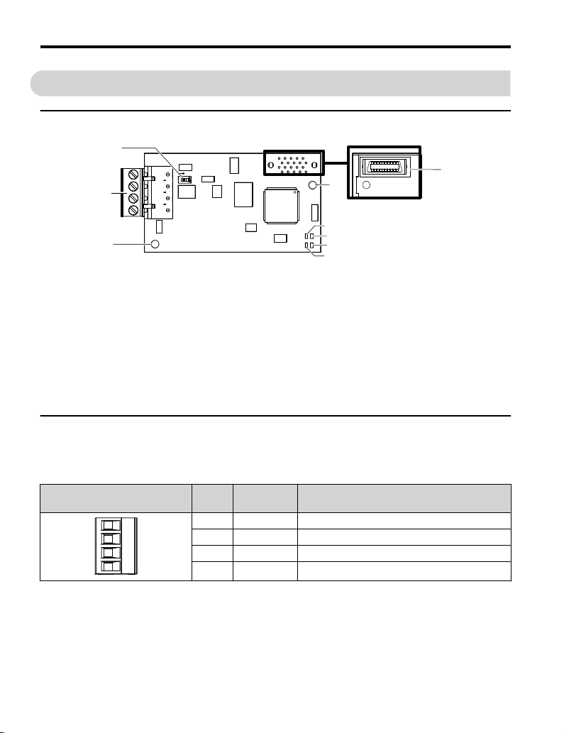
u
SI-J3/Metasys N2 or APOGEE FLN P1 Option
A – Ground terminal and
installation hole
B – Terminal block TB1
C – Terminating resistor
switch S1
D – Connector (CN5)
E – Installation hole
<1> Connect the ground wire provided in the option shipping package during installation.
<2> Refer to Option LED Display on page 11 for details on the LEDs.
u
Terminal Block TB1
<1>
Figure 1 Option (Top View)
F –
G –
H –
I –
LED (NS)
LED (MS)
LED (RX)
LED (TX)
<2>
<2>
<2>
<2>
Refer to Table 2 for details on removable terminal block TB1 terminal descriptions.
Table 2 Option Terminal Descriptions
Terminal
10
YASKAWA TOEP YAICOM 13 Metasys N2 & Apogee FLN P1 SI-J3 Installation & Technical Manual
Pin Signal Description
1 IG5 Isolated supply ground reference
2 + RX/TX (+) signal
3 - RX/TX (-) signal
4 SHLD Shield Ground
Page 11

4 Option Components
u
Option LED Display
The option has four LEDs.
Two bi-color Status LEDs:
• Module status (MS) red/green
• Network status (NS) red/green
Two Network LEDs:
• Transmit (TX) green
• Receive (RX) green
The operational states of the option LEDs after completion of the power-up diagnostic LED
sequence are described in Table 3. Wait at least 2 seconds for the power-up diagnostic process
to complete before verifying LED states.
Table 3 Option LED States
Name
MS
NS
TX
Display
Color Status
- OFF Power supply OFF Power is not being supplied to the drive.
Green ON Normal operation
Green Flashing Standby/Initializing
Red Flashing Minor fault
Red ON Major fault
Green/Red Flashing Option self-test The option is in self-test mode.
- OFF Power supply OFF -
Green ON Connected
Green Flashing Not connected
Red Flashing Minor fault A minor recoverable fault has occurred.
Red ON Major fault
Green/Red Flashing Network test Power-up sequence and testing
- OFF
Green Flashing
Operating Status Remarks
The option is operating normally and
initialization is complete.
The option is in process of configuring or
waiting for configuration information.
The option has detected a recoverable minor
fault such as incomplete configuration.
The option has detected an unrecoverable
major fault.
The device is currently communicating on the
network.
The device currently is not communicating, but
is correctly configured. The state is waiting for
communication to resume.
A non-recoverable major network fault has
occurred.
No data being sent to the
network
Data being sent to the
network
This node is not sending any data.
This node is sending network data.
YASKAWA TOEP YAICOM 13 Metasys N2 & Apogee FLN P1 SI-J3 Installation & Technical Manual
11
Page 12

4 Option Components
Name
RX
Power-Up Diagnostics
n
Display
Color Status
- OFF No data seen on the network
Green Flashing Data is seen on the network The option is connected to a network.
Operating Status Remarks
The option is not physically connected to the
network or there is no network activity.
An LED test is performed each time the drive is powered up. The initial boot sequence may
take several seconds. After the LEDs have completed the diagnostic LED sequence, the option
is successfully initialized. The LEDs then assume operational conditions as shown in
Table 3.
Table 4 Power-Up Diagnostic LED Sequence
Sequence Time Module Status (MS) Network Status (NS) Tx Rx
1 Initial OFF OFF OFF OFF
2 0.25 seconds Green OFF OFF OFF
3 0.25 seconds Red OFF OFF OFF
4 0.25 seconds OFF Green OFF OFF
5 0.25 seconds OFF Red OFF OFF
6 0.25 seconds OFF OFF Green OFF
7 0.25 seconds OFF OFF OFF Green
8 Run Time Go to proper state Go to proper state
Go to
proper state
Go to
proper state
12
YASKAWA TOEP YAICOM 13 Metasys N2 & Apogee FLN P1 SI-J3 Installation & Technical Manual
Page 13

5 Installation Procedure
5 Installation Procedure
u
Section Safety
DANGER
Electrical Shock Hazard
Do not connect or disconnect wiring while the power is on.
Failure to comply will result in death or serious injury.
Before installing the option, disconnect all power to the drive. The internal capacitor remains
charged even after the power supply is turned off. The charge indicator LED will extinguish
when the DC bus voltage is below 50 Vdc. To prevent electric shock, wait at least five
minutes after all indicators are off and measure the DC bus voltage level to confirm safe
level.
WARNING
Electrical Shock Hazard
Do not operate equipment with covers removed.
Failure to comply could result in death or serious injury.
The diagrams in this section may show drives without covers or safety shields to show
details. Be sure to reinstall covers or shields before operating the drives and run the drives
according to the instructions described in this manual.
Do not remove covers or touch circuit boards while the power is on.
Failure to comply could result in death or serious injury.
Do not allow unqualified personnel to use equipment.
Failure to comply could result in death or serious injury.
Installation, maintenance, inspection, and servicing must be performed only by authorized
personnel familiar with installation, adjustment, and maintenance of this product.
YASKAWA TOEP YAICOM 13 Metasys N2 & Apogee FLN P1 SI-J3 Installation & Technical Manual
13
Page 14

5 Installation Procedure
WARNING
Do not touch any terminals before the capacitors have fully discharged.
Failure to comply could result in death or serious injury.
Before installing the option, disconnect all power to the drive. The internal capacitor remains
charged even after the power supply is turned off. The charge indicator LED will extinguish
when the DC bus voltage is below 50 Vdc. To prevent electric shock, wait at least five
minutes after all indicators are off and measure the DC bus voltage level to confirm safe
level.
Do not use damaged wires, stress the wiring, or damage the wire insulation.
Failure to comply could result in death or serious injury.
Fire Hazard
Tighten all terminal screws to the specified tightening torque.
Loose electrical connections could result in death or serious injury by fire due to overheating
of electrical connections.
NOTICE
Observe proper electrostatic discharge procedures (ESD) when handling the drive and
circuit boards.
Failure to comply may result in ESD damage to the drive circuitry.
Do not use unshielded cable for control wiring.
Failure to comply may cause electrical interference resulting in poor system performance.
Use shielded, twisted-pair wires and ground the shield to the designated shield ground
location.
Check all the wiring to ensure that all connections are correct after installing the option
and connecting any other devices.
Failure to comply could result in damage to the option.
u
Prior to Installing the Option
Prior to installing the option, wire the drive, make necessary connections to the drive terminals,
and verify that the drive functions normally without the option installed. Refer to the Quick
Start Guide packaged with the drive for information on wiring and connecting the drive.
Figure 2 shows an exploded view of the drive with the option and related components for
reference.
14
YASKAWA TOEP YAICOM 13 Metasys N2 & Apogee FLN P1 SI-J3 Installation & Technical Manual
Page 15

I
J
K
M
A
L
D
F
G
C
E
B
H
NS MS
NS MS
TX RX
5 Installation Procedure
A – Drive front cover
B – Digital operator
C – LED label
D – Drive terminal cover
E – Removable tabs for wire
routing
F – Included screws
G – Ground wire
Figure 2 Drive Components with Option
u
Installing the Option
Remove the front covers of the drive before installing the option. Refer to the drive Quick
Start Guide for directions on removing the front covers. Cover removal varies depending on
drive size. This option can be inserted only into the CN5-A connector located on the drive
control board.
Preparing the Drive
Shut off power to the drive, wait the appropriate amount of time for voltage to
1.
dissipate, then remove the digital operator (B) and front covers (A, D). Front cover
removal varies by model.
YASKAWA TOEP YAICOM 13 Metasys N2 & Apogee FLN P1 SI-J3 Installation & Technical Manual
DANGER! Electrical Shock Hazard. Do not connect or disconnect wiring while the power is on.
Failure to comply will result in death or serious injury. Before installing the option, disconnect all
power to the drive. The internal capacitor remains charged even after the power supply is turned
off. The charge indicator LED will extinguish when the DC bus voltage is below 50 Vdc. To prevent
electric shock, wait at least five minutes after all indicators are off and measure the DC bus voltage
level to confirm safe level.
H – Drive grounding terminal
(FE)
I – Connector CN5-C
J – Connector CN5-B
K – Connector CN5-A
L – Insertion point for CN5
connector
M – SI-J3 option
15
Page 16

A
B
D
A
C
NS MS
TX RX
5 Installation Procedure
NOTICE: Damage to Equipment. Observe proper electrostatic discharge procedures (ESD) when
handling the option, drive, and circuit boards. Failure to comply may result in ESD damage to
circuitry.
Figure 3 Remove the Front Covers and Digital Operator
With the front covers and digital operator removed, apply the LED label (C) in the
2.
appropriate position on the drive top front cover (A).
Figure 4 Apply the LED Label
16
YASKAWA TOEP YAICOM 13 Metasys N2 & Apogee FLN P1 SI-J3 Installation & Technical Manual
Page 17

Connecting Option and Ground Wire
NS MS
K
L
F
M
TX RX
Insert the option (M) into the CN5-A connector (K) located on the drive and fasten it
1.
using one of the included screws (F).
Figure 5 Insert the Option
Connect the ground wire (G) to the ground terminal (H) using one of the remaining
2.
provided screws (F). Connect the other end of the ground wire (G) to the remaining
ground terminal and installation hole on the option (M) using the last remaining
provided screw (F) and tighten both screws to 0.5 ~ 0.6 N m or (4.4 ~ 5.3 in lbs).
5 Installation Procedure
YASKAWA TOEP YAICOM 13 Metasys N2 & Apogee FLN P1 SI-J3 Installation & Technical Manual
17
Page 18

NS MS
F
G
M
H
TX RX
5 Installation Procedure
Figure 6 Connect the Ground Wire
Wiring the Option
18
Note: There are two screw holes on the drive for use as ground terminals. When connecting three
options, two ground wires will need to share the same drive ground terminal.
Route the option wiring.
1.
Depending on the drive model, some drives may require routing the wiring through
the side of the front cover to the outside to provide adequate space for the wiring. In
these cases, using diagonal cutting pliers, cut out the perforated openings on the left
side of the drive front cover. Sharp edges along the cut out should be smoothed down
with a file or sand paper to prevent any damage to the wires.
Route the communication wiring inside the enclosure for drives that do not require
routing through the front cover. Refer to Table 5 and Figure 7 to determine the proper
wire routing by drive model.
YASKAWA TOEP YAICOM 13 Metasys N2 & Apogee FLN P1 SI-J3 Installation & Technical Manual
Page 19

A
B
5 Installation Procedure
Table 5 Communication Wire Routing Selection
Drive Series Model
CIMR-PU2A0004 to 0040;
CIMR-PU4A0002 to 0023;
P1000
iQpump1000
CIMR-PU5A0003 to 0011
CIMR-PU2A0056 and above;
CIMR-PU4A0031 and above;
CIMR-PU5A0023 and above
CIMR-PW2A0004 to 0040;
CIMR-PW4A0002 to 0023;
CIMR-PW5A0003 to 0011
CIMR-PW2A0056 and above;
CIMR-PW4A0031 and above;
CIMR-PW5A0023 and above
<1> Refer to Figure 7 for examples of the different wire routing techniques.
Wire Routing <1>
Through
Front Cover
Figure 7 (A) -
Figure 7 (A) -
Inside Drive
- Figure 7 (B)
- Figure 7 (B)
A – Route wires through the
openings provided on the
left side of the front
<1>
cover.
Figure 7 Wire Routing Examples
<1> The drive will not meet NEMA Type 1 requirements if wiring is exposed outside the enclosure.
Connect the network communication cables to the option modular connector terminal
2.
B – Use the open space
provided inside the drive
to route option wiring.
block (TB1).
Note: Separate the communications cables from the main circuit cables and other wiring and power
YASKAWA TOEP YAICOM 13 Metasys N2 & Apogee FLN P1 SI-J3 Installation & Technical Manual
cables. Use properly grounded shielded cables for the communication cables to prevent
problems caused by electrical interference.
19
Page 20

DRIVE
M
U/T1
V/T2
W/T3
R/L1
S/L2
T/L3
SI-J3
Option
FE
CN5-A
CN1
TB1
IG5
+
-
Shield
RX/TX (+) Signal
RX/TX (-) Signal
MotorPower
Metasys N2
or
APOGEE FLN P1
5 Installation Procedure
Connection Diagram
n
Figure 8 Connection Diagram
20
YASKAWA TOEP YAICOM 13 Metasys N2 & Apogee FLN P1 SI-J3 Installation & Technical Manual
Page 21

Figure 9 explains the wiring for multiple connections.
CONTROLLER
IG
+
-
SHLD
+
-
SHLD
DRIVE
SI-J3
N2-P1
S1
ON
S1
OFF
IG
+
-
SHLD
DRIVE
SI-J3
N2-P1
S1
OFF
IG
+
-
SHLD
DRIVE
SI-J3
N2-P1
Drive Drive Drive
Metasys N2 or
APOGEE FLN P1
Field Controller
A1000
CIMR-AU5A0009FAA
600V 3Phase 5.5kW/3.7kW
A1000
CIMR-AU5A0009FAA
600V 3Phase 5.5kW/3.7kW
A1000
CIMR-AU5A0009FAA
600V 3Phase 5.5kW/3.7kW
Figure 9 Connection Diagram for Multiple Connections
5 Installation Procedure
Figure 10 System Overview-Connecting Multiple Drives to the Network
The two ends of the network must be terminated with a 120 ohm resistor between the “+” and
“-” and signals. The SI-J3 has a built in termination resistor that can be enabled or disabled
using DIP switch S1. If a drive is located at the end of a network line, enable the termination
resistor by setting DIP switch S1 to the ON position. Disable the termination resistor on all
slaves that are not located at the end of the network line by setting DIP switch S1 to the OFF
position (The factory setting for DIP switch S1 is OFF).
YASKAWA TOEP YAICOM 13 Metasys N2 & Apogee FLN P1 SI-J3 Installation & Technical Manual
21
Page 22

D
A
B
NS MS
TX RX
5 Installation Procedure
Replacing the Drive Covers and Digital Operator
Replace and secure the front covers of the drive (A, D) and replace the digital operator
1.
(B).
Figure 11 Replace the Front Covers and Digital Operator
Note: Take proper precautions when wiring the option so that the front covers will easily fit back onto
the drive. Make sure no cables are pinched between the front covers and the drive when
replacing the covers.
22
YASKAWA TOEP YAICOM 13 Metasys N2 & Apogee FLN P1 SI-J3 Installation & Technical Manual
Page 23

6 Related Drive Parameters
6 Related Drive Parameters
The following parameters are used to set up the drive for operation with the option. Parameter
setting instructions can be found in the drive Quick Start Guide or Technical Manual.
Confirm proper setting of the all parameters in Table 6 before starting network
communications. After changing parameter settings, cycle power to the drive for the new
settings to take effect.
Table 6 Related Parameters
No. Name Description Values
Frequency Reference
b1-01
Selection
<1>
Run Command
b1-02
Selection
Operation Selection
F6-01
after
(3A2)
Communications
Error
External Fault
F6-02
Detection Conditions
(3A3)
(EF0)
Stopping Method for
F6-03
External Fault from
(3A4)
the Communication
Option
Reset
F6-08
Communication
(36A)
Related Parameters
F6-75 P1-N2 Protocol Select
P1-N2 Comm Fault
F6-76
Enable
P1-N2 Comm Fault
F6-77
Time
Selects the frequency reference input source.
0: Operator-Digital preset speed d1-01 to d1-17
1: Terminals-Analog input terminal A1 or A2
2: MEMOBUS/Modbus communications
3: Option PCB
4: Pulse Input (Terminal RP)
Selects the run command input source.
0: Digital Operator-RUN and STOP keys
1: Digital input terminals S1 to S7
2: MEMOBUS/Modbus communications
3: Option PCB
Determines drive response when a bUS error is detected during
communications with the option.
0: Ramp to Stop
1: Coast to Stop
2: Fast-Stop
3: Alarm Only
Sets the condition for external fault detection (EF0).
0: Always detected
1: Detected only during operation
Determines drive response for external fault input (EF0)
detection during option communications.
0: Ramp to Stop
1: Coast to Stop
2: Fast-Stop
3: Alarm Only
Determines if communication-related parameters F6- and F7are set back to original default values when the drive is
initialized using parameter A1-03.
0: Do not reset parameters
1: Reset parameters
1: N2
2: P1
0: Disabled
1: Enabled
Seconds before declaring Comm Fault
Default: 1
Range: 0 to 4
(Set to 3 for Metasys
N2 or APOGEE
FLN P1)
Default: 1
Range: 0 to 3
(Set to 3 for Metasys
N2 or APOGEE
FLN P1)
Default: 1
Range: 0 to 3
Default: 0
Range: 0, 1
Default: 1
Range: 0 to 3
Default: 0
Range: 0, 1
Default: 2
Range: 1, 2
Default: 1
Range: 0, 1
Default: 2.0
0.0 to 10.0 Seconds
YASKAWA TOEP YAICOM 13 Metasys N2 & Apogee FLN P1 SI-J3 Installation & Technical Manual
23
Page 24

6 Related Drive Parameters
No. Name Description Values
F6-78 P1-N2 Node Address
F6-79
P1 Baud Rate Select
<2>
<1> Set b1-02 to 3 to start and stop the drive with the option master device using serial communications. Set b1-01
to 3 to control the drive frequency reference via the master device.
<2> N2 will always be set at 9600 Baud Rate.
No. Name Description Values
U6-98 First Fault First Option Fault -
U6-99 Current Fault Current Option Fault -
Network Node Address
Network Physical Address
2: 4800
3: 9600
Table 7 Option Monitors
Default: 1
Range: 0 to 255
Default: 3
Range: 2, 3
24
YASKAWA TOEP YAICOM 13 Metasys N2 & Apogee FLN P1 SI-J3 Installation & Technical Manual
Page 25

7 Network Drive Operations
7 Network Drive Operations
The drive operations that can be performed by Metasys N2 or APOGEE FLN P1
communication depend on drive parameter settings. This section explains the functions that
can be used and related parameter settings.
u
Observing the Drive Operation
A controller can perform the following actions with network communications at any time
regardless of parameter settings:
• observe drive status and drive control terminal status from a controller
• read and write parameters
• set and reset faults
• set multi-function inputs.
Note:
u
Select an external reference and adjust the parameters in Table 8 accordingly to start and stop
the drive or set the frequency reference using Metasys N2 or APOGEE FLN P1
communications.
Reference Source Parameter Name Required Setting
External Reference 1
External Reference 2
Input settings from the input terminals So and from network communications are both linked by a logical
OR operation.
Controlling the Drive
Table 8 Setting Parameters for Drive Control from Metasys N2 or APOGEE FLN P1
b1-01 Frequency Reference Selection 1 3
b1-02 Run Command Selection 1 3
b1-15 Frequency Reference Selection 2 3
b1-16 Run Command Selection 2 3
YASKAWA TOEP YAICOM 13 Metasys N2 & Apogee FLN P1 SI-J3 Installation & Technical Manual
25
Page 26

8 Communications Timing
8 Communications Timing
To prevent a communications overrun in the slave drive, the master should wait a certain time
between sending messages to the same drive. Similarly, the slave drive must wait before
sending response messages to prevent an overrun in the master. This section explains the
message timing.
u
Command Messages from Master to Drive
The master must wait for a specified time between receiving a response and resending the
same type of command to the same slave drive to prevent overrun and data loss. The minimum
wait time depends on the command as shown in Table 9.
Table 9 Minimum Wait Time for Sending Messages
Example Minimum Wait Time
• Control command (Run, Stop) Write parameters
• Set inputs/outputs
• Read monitors and parameter values
PLC→Drive PLC→DriveDrive→PLC
Command message Response message Command message
5 ms
Time
24 bit length
Figure 12 Minimum Wait Time for Sending Messages
Master Send
Wait Time
Set a timer in the master to check how long it takes for the slave drive(s) to respond to the
master. The master should try resending the message if no response is received within a certain
amount of time.
26
YASKAWA TOEP YAICOM 13 Metasys N2 & Apogee FLN P1 SI-J3 Installation & Technical Manual
Page 27

Time
Command message Response message Command message
PLC→Drive PLC→DriveDrive→PLC
24 bit length
5 ms
8 Communications Timing
u
Response Messages from Drive to Master
The drive will process the data received and wait at least 5 ms before it responds if the drive
receives a command from the master.
Figure 13 Minimum Response Wait Time
YASKAWA TOEP YAICOM 13 Metasys N2 & Apogee FLN P1 SI-J3 Installation & Technical Manual
27
Page 28

9 Metasys N2 Communications
9 Metasys N2 Communications
u
Drive Functions
Each of the following functions must be enabled during start-up of the drive:
Start and Stop the Drive
n
Set the Run Forward Command (BO 1) to run the drive in the forward direction. Set the Run
Reverse Command (BO 2) to run the drive in the reverse direction. Run/Stop Monitor (BI 1)
shows the current run status of the drive. Forward/Reverse Monitor (BI 2) shows the current
direction.
NOTICE: Damage to Equipment. Improper drive direction may damage HVAC equipment if parameter b1-04,
Reverse Enable, is set to 0 (Enable). Confirm proper motor rotation prior to connecting the load to the motor.
Lock the Drive Panel
n
Locking the panel prevents the user from using the LOCAL/REMOTE and STOP keys locally
at the drive panel. Panel Lock (BO 10) can be commanded to lock and unlock the panel.
Digital Inputs
n
Multi-Function Input S3 (BO 5) through Multi-Function Input S7 (BO 9) are physical digital
inputs on the drive. They can be set either by external devices, such as limit or pressure
switches, or by the network. Their function depends on how the drive has been programmed.
Refer to the drive manual section on Multi-Function Inputs (H1-03 through H1-07) for detailed
information on the use and programming of the multi-function inputs. The multi-function
input status can be monitored through Multi-Function Input 1 Monitor (BI 14) through MultiFunction Input 5 Monitor (BI 19).The multi-function inputs can be set by both external devices
or over the network.
Note: The multi-function inputs can be set by both external devices or over the network. Use caution when
connecting the multi-function inputs to external devices to ensure correct system operation.
Loop Gain
n
PI Proportional Gain (AO 4) and PI Integral Time (AO 5) are the gain and integral time
parameters used by the drive. The PI loop is structured differently than the Metasys loop.
Refer to the drive manual section on PID for information on how the PI loop functions.
28
YASKAWA TOEP YAICOM 13 Metasys N2 & Apogee FLN P1 SI-J3 Installation & Technical Manual
Page 29

9 Metasys N2 Communications
Reading and Resetting Faults
n
The Fault Monitor (BI 4) and Drive Ready Monitor (BI 3) show the current status of the drive.
The Fault Code (AI 10) contains the code for the most current fault. The LST Fault Code (AI
19) contains the code for the previous fault. Refer to Drive Fault Trace Register Contents
on page 51 for the purpose of interpreting fault codes. The drive faults can be reset through
the Fault Reset Command (BO 4). The Fault Reset Command is only available when the Run
Forward Command and the Run Reverse Command are both OFF.
Set a timer in the master to check how long it takes for the slave drive(s) to respond to the
master. The master should try resending the message if no response is received within a certain
amount of time.
u
Metasys N2 Point Database
This section describes the Metasys N2 point database. This database features logical points:
Analog Inputs (AI), Analog Outputs (AO), Binary Inputs (BI) and Binary Outputs (BO). These
points configure, control, and monitor the operation of the drive.
Metasys N2 Analog Input (AI) Summary
n
Table 10 Metasys N2 Analog Input Summary (SI-J3 to Metasys N2)
Object ID Object Name Units Yaskawa Drive Parameter
AI 1 Speed Reference 0.01 Hz U1-01
AI 2 Output Sped 0.01 Hz U1-02
AI 3 Output Current 0.1 A U1-03
AI 4 kWatt Hour Meter kWh U4-10
AI 5 Output Power 0.1 kWh U1-08
AI 6 Drive Temperature 1 °C U4-08
AI 7 PI Feedback 0.01% U5-01
AI 8 AC Output Voltage 0.1 Vac U1-06
AI 9 DC Bus Voltage 1 Vdc U1-07
AI 10 Fault Code - U2-01
AI 11 Elapsed Time - Hours 1 hour U4-01
AI 12 Elapsed Time - 10K Hours 10K hours U4-01
AI 13 MWatt Hour meter MWh U4-11
AI 14 Drive Rated Current A n9-01
AI 15 Communication Error Code - -
AI 16 PI Deviation 0.01% U5-02
AI 17 PI Output Capacity 0.01% U5-03
AI 18 PI Reference 0.01% U5-04
AI 19 Last Fault Code - U2-02
YASKAWA TOEP YAICOM 13 Metasys N2 & Apogee FLN P1 SI-J3 Installation & Technical Manual
29
Page 30

9 Metasys N2 Communications
Object ID Object Name Units Yaskawa Drive Parameter
AI 20 Freq Ref @ Fault 0.01 Hz U2-03
AI 21 Output Freq @ Fault 0.01 Hz U2-04
AI 22 Output Current @ Fault 0.1 A U2-05
AI 23 Out Volt Ref @ Fault 0.1 Vac U2-07
AI 24 DC Bus Volts @ Fault 1 Vdc U2-08
AI 25 Output Power @ Fault 0.1 kW U2-09
AI 26 Input Term Status @ Fault - U2-11
AI 27 Output Term Status @ Fault - U2-12
AI 28 Operation Status @ Fault - U2-13
AI 29 Elapsed Operation Time @ Fault 1 hour U2-14
AI 30 Most Recent Fault - U3-01
AI 31 2nd Most Recent Fault - U3-02
AI 32 3rd Most Recent Fault - U3-03
AI 33 4th Most Recent Fault - U3-04
AI 34 Elapsed Time @ Current Fault 1 hour U3-11
AI 35 Elapsed Time @ 2nd Fault 1 hour U3-12
AI 36 Elapsed Time @ 3rd Fault 1 hour U3-13
AI 37 Elapsed Time @ 4th Fault 1 hour U3-14
AI 38 Read Parameter Data - -
Metasys N2 Analog Output (AO) Summary
n
Table 11 Metasys N2 Analog Output Summary ( Metasys N2 to SI-J3)
Object
ID
AO 1 Speed Command 0.01 Hz - -
AO 2 Acceleration Time seconds 30.0 C1-01
AO 3 Deceleration Time seconds 30.0 C1-02
AO 4 PI Proportional Gain - 2.00 b5-02
AO 5 PI Integral Time seconds 5.0 b5-03
AO 6 Stall Prevention Level – Run % 120 L3-06
AO 7 Stall Prevention Level – Accel % 120 L3-02
AO 8 Reference Operation Mode Select - 1 b1-01
AO 9 Run Operation Mode Select - 1 b1-02
AO 10 PI Mode Select - 0 b5-01
AO 11 Frequency Command Upper Limit % of Max 100.0 d2-01
AO 12 Frequency Command Lower Limit % of Max 0.0 d2-02
Object Name Units Default Value
Yaskawa Drive
Parameter
30
YASKAWA TOEP YAICOM 13 Metasys N2 & Apogee FLN P1 SI-J3 Installation & Technical Manual
Page 31

9 Metasys N2 Communications
Object
ID
AO 13 Motor Rated Current A Motor model dependent E2-01
AO 14 Jump Frequency 1 0.1 Hz 0.0 d3-01
AO 15 Jump Frequency 2 0.1 Hz 0.0 d3-02
AO 16 Jump Frequency 3 0.1 Hz 0.0 d3-03
AO 17 Jump Frequency Bandwidth 0.1 Hz 1.0 d3-04
AO 18 Number of Auto Restarts - 0 L5-01
AO 19 Operator Display Mode - 0 o1-03
AO 20 Power Loss Ride-Thru seconds Drive model dependent L2-02
AO 21 Cable Loss Timeout seconds 2.0 F6-77
AO 22 Cable Loss Speed 0.01 Hz 0.00 d1-04
AO 23 PI Integral Limit 0.1% 100.0 b5-04
AO 24 PI Upper Limit Value 0.1 100.0 b5-06
AO 25 PI Offset Adjustment 0.1 0.0 b5-07
AO 26 PI Primary Delay Time 0.01 0.00 b5-08
AO 27
AO 28
AO 29
AO 30 Read Parameter Number - - -
AO 31 Write Parameter Number - - -
AO 32 Write Parameter Data - - -
Metasys N2 Binary Input (BI) Summary
n
Object Name Units Default Value
PI Feedback Reference Missing
Detection Select
PI Feedback Reference Missing
Detection Level
PI Feedback Reference Missing
Detection Time
1 0 b5-12
1% 0 b5-13
0.1 s 1.0 b5-14
Yaskawa Drive
Parameter
Table 12 Metasys N2 Binary Input Summary (SI-J3 to Metasys N2)
Object
ID
BI 1 Run/Stop Monitor 0 Stopped Running
BI 2 Forward/Reverse Monitor 0 Forward Reverse
BI 3 Drive Ready Monitor 0 Not Ready Ready
BI 4 Fault Monitor 0 Not Faulted Faulted
BI 5 Zero Speed 0 Not Zero Speed Zero Speed
BI 6 Speed Agree 0 Not Speed Agree Speed Agree
BI 7 Minor Fault 0 No Minor Fault Minor Fault
BI 8 Major Fault 0 No Major Fault Major Fault
BI 9
Object Name Default Off (0) State On (1) State
Drive Communication Error
Monitor
0 No Error Error
YASKAWA TOEP YAICOM 13 Metasys N2 & Apogee FLN P1 SI-J3 Installation & Technical Manual
31
Page 32

9 Metasys N2 Communications
Object
ID
BI 10
BI 11
BI 12
BI 13 Safety Interlock Monitor 0 Safety Clear Terminal 3 Closed Safety Set Terminal 3 Open
BI 14
BI 14
BI 16
BI 17
BI 18
BI 19
Metasys N2 Binary Output (BO) Summary
n
Object Name Default Off (0) State On (1) State
Multi-Function Output 1
(H2-01)
Multi-Function Output 2
(H2-02)
Multi-Function Output 3
(H2-03)
HAND/AUTO Reference
Monitor
Multi-Function Input S3
Monitor
Multi-Function Input S4
Monitor
Multi-Function Input S5
Monitor
Multi-Function Input S6
Monitor
Multi-Function Input S7
Monitor
0 Off On
0 Off On
0 Off On
0 REMOTE LOCAL
0 Off On
0 Off On
0 Off On
0 Off On
0 Off On
Table 13 Metasys N2 Binary Output Summary (Metasys N2 to SI-J3)
Object ID Object Name Default Off (0) State On (1) State
BO 1 Run Forward Command 0 Stop Forward
BO 2 Run Reverse Command 0 Stop Reverse
BO 3 Serial Fault (EF0) Command 0 No Fault Fault
BO 4 Fault Reset Command 0 No Reset Reset
BO 5 Multi-Function Input S3 (H1-03) 0 Off On
BO 6 Multi-Function Input S4 (H1-04) 0 Off On
BO 7 Multi-Function Input S5 (H1-05) 0 Off On
BO 8 Multi-Function Input S6 (H1-06) 0 Off On
BO 8 Multi-Function Input S7 (H1-07) 0 Off On
BO 10 Panel Lock 0
BO 11 Communication Fault Enable 0
LOCAL/REMOTE and Stop/
Reset Keys Enabled
BUS Fault Not Activated if
Cable Loss Occurs
LOCAL/REMOTE and
Stop/Reset Keys Disabled
BUS Fault Activated if
Cable Loss Occurs
u
Metasys N2 Cable Loss Configuration and Behavior
This section describes the configurable cable loss feature of the drive. This feature offers a
user maximum flexibility in determining drive response to a loss of communication.
32
YASKAWA TOEP YAICOM 13 Metasys N2 & Apogee FLN P1 SI-J3 Installation & Technical Manual
Page 33

9 Metasys N2 Communications
Drive Behavior at Loss of Communication
n
The drive can be configured to respond to an interval without receipt of a message in one of
the following methods:
• Continue at last speed
• Continue at last speed with alarm
• Continue at preset speed
• Ramp to Stop with EF0 fault
• Coast to Stop with EF0 fault
• Emergency Stop with EF0 fault
Metasys N2 I/O
n
Three Metasys N2 outputs are used to select the desired behavior:
• AO 21 -Cable Loss Timeout
• AO 22 -Cable Loss Speed
• BO 11 -Communication Fault
Table 14 Cable Loss Behavior Summary
Behavior F6-01
Decelerate to stop (stop time in C1-02)
BUS fault
Coast to stop BUS fault 1 Timeout Interval X On
Emergency stop (stop time in C1-09)
BUS fault
Continue at last speed 3 0 X X
Continue at last speed with alarm 3 Timeout Interval X On
Continue at preset speed with alarm
<1> Not all drives support setting F6-01=4.
Note: 1. Communication must first be established and then lost for these features to function as described. A
communications timeout does not occur if a drive is powered-up without a cable connected or with
the master controller offline.
2. A run command must have been issued (BO 1=ON or BO 2=ON) prior to loss of communications
for modes that describe the drive running after a communications timeout. The drive will not
automatically restart from a stopped condition for safety purposes. Additional external wiring is
required (consult factory) if a user requires the drive to restart automatically.
<1>
Cable Loss Timeout
(AO 21)
0 Timeout Interval X On
2 Timeout Interval X On
4 Timeout Interval Preset Speed On
Cable Loss Speed
(AO 22)
Communication
Fault
Enable
(BO 11)
A BUS fault will be declared and will remain until communication is restored upon expiration
of the communications timeout interval.
YASKAWA TOEP YAICOM 13 Metasys N2 & Apogee FLN P1 SI-J3 Installation & Technical Manual
33
Page 34

9 Metasys N2 Communications
Continue at Last Speed
n
Cable Loss Timeout (AO 21) is set to 0, disabling the cable loss feature in this mode. The
other two settings Cable Loss Speed (AO 22) and Communication Fault Enable (BO 11) are
ignored. The drive simply maintains its last commanded state if communication is lost. The
drive will not display an alarm or fault to indicate it has lost communication. This behavior
can also be achieved by setting parameter F6-01 to 3. The drive will display an alarm and
continue running. The Communication Fault Enable (BO 11) must be enabled and Cable Loss
Timeout (AO 21) should be set to a value other than 0 for this specific condition.
Continue at Preset Speed
n
Cable Loss Timeout (AO 21) is set to the desired interval, Cable Loss Speed (AO 22) is set
to the desired preset speed and F6-01 is set to 4 in this mode. The drive speed command (AO
1) is set to the Cable Loss Speed (AO 22) and the drive continues running at this new speed
if the time between messages exceeds the timeout interval. Communication Fault Enable (BO
11) must be set to ON.
Stop with Fault (BUS)
n
Communication Fault Enable (BO 11) must be set to ON. Cable Loss Timeout (AO 21) is set
to the desired interval and parameter F6-01 is set to a value of 0,1 or 2 in this mode. If the
time between messages exceeds the timeout interval, the drive will declare a BUS fault and
the drive speed command (AO 1) will be set to 0. The stopping method is determined by the
setting of F6-01.
• F6-01=0 selects Ramp to Stop. The deceleration time or the slope of the ramp is determined
by the setting of drive parameter C1-02.
• F6-0 =1 selects Coast to Stop. The drive does not attempt to control the rate of deceleration.
• F6-0 =2 selects Emergency or Fast Stop. The deceleration time is determined by the setting
of drive parameter C1-09.
Note: The behavior of the drive at cable loss is controlled by parameter F6-01. This drive parameter works
with the points as described in the table above to determine how the drive will respond to a cable loss.
The drive will continue in its last state if the cable loss fault is disabled. The drive will continue to run
at the last commanded frequency if running.
34
YASKAWA TOEP YAICOM 13 Metasys N2 & Apogee FLN P1 SI-J3 Installation & Technical Manual
Page 35

9 Metasys N2 Communications
u
Metasys N2 Mailbox Function
Reading Drive Parameters
n
Two points are defined for reading drive parameters:
• AO 30 - Specifies the parameter to be read from the drive.
• AI 38 - Reports the value of the parameter specified in AO 30.
The mailbox retrieves data from the parameter and sends it to the controller when this point
is read.
Example: Writing a value of 387 (183 hex) to AO 30 specifies drive parameter b1-04. Reading
AI 38 returns the current setting of parameter b1-04 to the controller.
Writing Drive Parameters
n
Two points are defined for writing drive parameters:
• AO 31 - Specifies the parameter to be written to.
• AO 32 - Entry location of the value to be written to the parameter specified in AO 31. The
mailbox will write the value to the drive when this point is written. An ENTER or ACCEPT
command does not need to be sent for the data to be taken by the drive. The behavior of
the write is the same as with the digital operator. There are a limited number of drive
parameters that can be written to when the drive is running.
Example: Writing a value of 387 (183 hex) to AO 31 specifies drive parameter b1-04. Writing
a value of 1 to AO 32 sets b1-04 to 1 and enables the drive for reverse run.
YASKAWA TOEP YAICOM 13 Metasys N2 & Apogee FLN P1 SI-J3 Installation & Technical Manual
35
Page 36

(Desired Range) x (Slope of Existing Point)
(Range of Existing Point)
New Slope =
(60 - 0) Hz x (0.01)
(100 - 0)%
New Slope =
= 0.006
(Desired Range) x (Slope of Existing Point)
(Range of Existing Point)
New Slope =
(250 - 30) °F x (0.1)
(100 - 0)%
New Slope =
= 0.22
10 APOGEE FLN P1 Communications
10 APOGEE FLN P1 Communications
u
Slope and Intercept Conversion
Several drive parameters are available for monitoring purposes. The available parameters include
FREQ OUTPUT (Point 3), SPEED (Point 5), CURRENT (Point 6), TORQUE (Point 7), POWER
(Point 8), DRIVE TEMP (Point 9), KWH (Point 10), and RUN TIME (Point 12). These points can
be unbundled for monitoring or used in various global control strategies.
u
Drive Controlled Feedback
The most typical application is Supervisory Control. The sensor for the control variable (e.g.,
water temperature) is hard-wired to the drive and the control device (fan) is modulated using
the PI control loop built into the drive. The setpoint for the control variable (water temperature
set point) is unbundled and commanded by the field panel, based on the building control
strategy implemented in PPCL.
The point to unbundle and command for the set point is INPUT REF 1 (Point 60) when this
strategy is used. The control variable (e.g., water temperature) can be monitored by unbundling
PI FEEDBACK (Point 62). These points are provided in units of percent, where 0% and 100%
correspond to the range of the sensor being used to measure the control variable. These points
have default units in Hz. Unbundle these points with appropriate slopes and intercepts if other
units are required. The new intercept will be equal to the lowest value of the desired range.
The following formulas allow the user to define a new slope and intercept to convert the unit.
The following formulas allow the user to define a new slope and intercept to convert the unit.
Conversion Example
n
The drive is controlling a fan, which in turn is controlling the water temperature from a cooling
tower. The temperature sensor has a range of -1 °C to +121 °C (30 °F to 250 °F). To unbundle
the set point (INPUT REF 1), for commanding in degrees Fahrenheit, where 0 to 60 Hz is equal
to -1 °C to +121 °C: New Intercept=30 (the temperature that corresponds to 0%).
Note: 1. Desired Range=Range Maximum - Range Minimum
2. Range of Existing Point=Existing Range Maximum - Existing Range Minimum
36
YASKAWA TOEP YAICOM 13 Metasys N2 & Apogee FLN P1 SI-J3 Installation & Technical Manual
Page 37

(Desired Range) x (Slope of Existing Point)
(Range of Existing Point)
New Slope =
(250 - 30) °F x (0.1)
(100 - 0)%
New Slope =
= 0.022
10 APOGEE FLN P1 Communications
u
Field Panel Controlled Feedback
The sensor is connected to the APOGEE FLN network at a remote location and the control
loop is executed in PPCL using this strategy. The drive speed command is passed from the
field panel to the drive by commanding INPUT REF 1 (Point 60).
NOTICE: Damage to Equipment. Avoid using this strategy. This strategy is not recommended because it
means that the loop is being closed over the network. Delays due to processor scan time and network traffic
can cause control to be degraded or lost and damage to HVAC equipment may result.
Unbundle the Feedback
n
Unbundling the feedback (PI FEEDBACK) for monitoring in degrees Fahrenheit:
New Intercept = 30
Note: 1. Desired Range=Range Maximum - Range Minimum
2. Range of Existing Point=Existing Range Maximum - Existing Range Minimum
u
Other Functionalities
Enable the following functions during start-up of the drive:
Enable the Drive to Run
n
RUN ENABLE (Point 35) can be commanded to require the drive to have a physical input
(Terminal S3) set before the drive can run. This works in conjunction with CMD RUN.STOP
(Point 24) or the CMD REV.STOP (Point 22). If RUN ENABLE (Point 35) is commanded
ON then terminal S3 needs to be on and CMD RUN.STOP (Point 24) or CMD REV.STOP
(Point 22) needs to be commanded ON for the drive to run.
Alternately, RUN ENABLE (Point 35) is commanded OFF, then to run the drive CMD
RUN.STOP (Point 24) or CMD REV.STOP (Point 22) is the only point that needs to be
commanded ON.
Start and Stop the Drive
n
CMD RUN.STOP (Point 24) can be commanded to run the drive in the forward direction.
STOP.RUN (Point 23) shows the current status of the drive.
YASKAWA TOEP YAICOM 13 Metasys N2 & Apogee FLN P1 SI-J3 Installation & Technical Manual
37
Page 38

10 APOGEE FLN P1 Communications
Change Directions
n
CMD REV.STOP (Point 22) can be commanded to run the drive in the reverse direction.
FWD.REV (Point 21) shows the current direction of the drive rotation.
NOTICE: Damage to Equipment. Improper drive direction may damage HVAC equipment if parameter b1-04,
Reverse Enable, is improperly set (b1-04=0). Confirm proper motor rotation prior to connecting the load to
the motor.
Lock the Drive Panel
n
Locking the panel prevents the user from using the LOCAL/REMOTE and STOP keys locally
at the drive panel. LOCK PANEL (Point 33) can be commanded to lock and unlock the panel.
Digital Outputs
n
MULTI OUT 1 (Point 40), MULTI OUT 2 (Point 41), and MULTI OUT 3 (Point 42) are
physical digital outputs on the drive. Their purpose depends on how the drive has been setup. The drive can be programmed so that these points can display various limits, warnings,
and status conditions. Some examples include frequency limit, over current, and motor over
temperature fault.
Loop Gain
n
PID P GAIN (Point 63) and PID I TIME (Point 64) are the gain and integral time parameters
similar to the P and I gains in the APOGEE FLN Terminal Equipment Controllers. The PI
loop of the drive is structured differently than the Siemens loop, so there is not a one-to-one
correspondence between the gains.
Reading and Resetting Faults
n
OK.FAULT (Point 93) shows the current status of the drive. FAULT CODE (Point 17)
contains the code for the most current fault. LST FLT CODE (Point 66) contains the code for
the previous fault. Refer to APOGEE FLN P1 Application 2721 Point Number Summary
on page 39 for descriptions of the fault codes. The drive can be reset back to OK mode by
commanding RESET FAULT (Point 94) to RESET. The RESET FAULT command is only
available when the CMD RUN.STOP (Point 24) and CMD REV.STOP (Point 22) are both
STOP.
u
APOGEE FLN Point Database
This section shows the APOGEE FLN point database for Application 2721.
APOGEE FLN Point List Summary
n
This database is for APOGEE FLN Application 2721 and features logical points: Logical
Analog Inputs (LAI), Logical Analog Outputs (LAO), Logical Digital Inputs (LDI) and
Logical Digital Outputs (LDO). These points configure, control or monitor the operation of
the drive.
38
YASKAWA TOEP YAICOM 13 Metasys N2 & Apogee FLN P1 SI-J3 Installation & Technical Manual
Page 39

10 APOGEE FLN P1 Communications
Information to consider when referencing this table:
1. Points not listed are not used in this application.
2. A single value in a column means that the value is the same in English units and in SI
units.
3. Point numbers that appear in bold type (e.g. 03) can be unbundled at the field panel.
Table 15 APOGEE FLN P1 Application 2721 Point Number Summary
Point
Point
No.
Type
01 LAO CTLR ADDRESS 31 - 1 0 - - F6-78
02 LAO APPLICATION - - 1 0 - - -
03 LAI FREQ OUTPUT 0 Hz 0.01 0 - - U1-02
04 LAI PCT OUTPUT 0 % 0.01 0 - - -
05 LAI SPEED 0 RPM 1 0 - - -
06 LAI CURRENT 0 A 0.01 0 - - U1-03
07 LAI TORQUE 0 % 0.1 0 - - U1-09
08 LAI POWER 0 kW 0.1 0 - - U1-08
09 LAI DRIVE TEMP 0 ° C/F 1 0 - - U4-08
10 LAI DRIVE KWH 0 kWh 0.1 0 - - U4-10
11 LAI MWH 0 MWh 1 0 - - U4-11
12 LAI RUN TIME 0 h 1 0 - - U4-01
13 LAI DC BUS VOLT 0 V 1 0 - - U1-07
14 LAI AC OUT VOLT 0 V 0.1 0 - - U1-06
15 LAI PAR N9.01 0 A 0.01 0 - - n9-01
16 LAI RUN TIMEX10K 0 10Kh 1 0 - - U4-01
17 LAI FAULT CODE 0 - 1 0 - - U2-01
18 LDI MINOR FLT NO FLT - 1 0 FAULT NO FLT
19 LDI MAJOR FLT NO FLT - 1 0 FAULT NO FLT
20 LAO OVRD TIME 1 h 1 0 - - -
21 LDI FWD.REV FWD - 1 0 REV FWD
22 LDO CMD REV.STOP STOP - 1 0 REV STOP -
23 LDI RUN.STOP STOP - 1 0 RUN STOP
24 LDO CMD RUN.STOP STOP - 1 0 FWD STOP -
Point Name
Factory
Default
(SI Units)
Units
(SI Units)
Slope
(SI Units)
Intercept
(SI Units)OnText
Off
Text
Parameter
U1-12
(Bit 6)
U1-12
(Bit 7)
U1-12
(Bit 2)
U1-12
(Bit 0)
YASKAWA TOEP YAICOM 13 Metasys N2 & Apogee FLN P1 SI-J3 Installation & Technical Manual
39
Page 40

10 APOGEE FLN P1 Communications
Point
Point
No.
Type
25 LDI ZERO SPEED OFF - 1 0 ON OFF
26 LDI SPEED AGREE NO AGR - 1 0 AGREE NO AGR
27 LDI DRIVE READY NOTRDY - 1 0 READY NOTRDY
28 LDI LOC.REM MON REMOTE - 1 0 LOCAL REMOTE -
29 LDO DAY.NGT DAY - 1 0 NGT DAY -
30 LAO CURRENT LMT 0 A 0.01 0 - - E2-01
31 LAO ACCEL TIME 0 s 0.1 0 - - C1-01
32 LAO DECEL TIME 0 s 0.1 0 - - C1-02
33 LDO LOCK PANEL UNLOCK - 1 0 LOCK UNLOCK -
35
<1>
36 LAO STALL PRE RN 90 % 1 30 - - L3-06
37 LAO STALL PRE AC 120 % 1 0 - - L3-02
38 LAO FREQ UP LIM 100 % 0.1 0 - - d2-01
39 LAO FREQ LOW LIM 0 % 0.1 0 - - d2-02
40 LDI MULTI OUT 1 OFF - 1 0 ON OFF
41 LDI MULTI OUT 2 OFF - 1 0 ON OFF
42 LDI MULTI OUT 3 OFF - 1 0 ON OFF
43 LDI SAFETY ILOCK OFF - 1 0 ON OFF
44 LDO MF INP 1 OFF - 1 0 ON OFF -
45 LDO MF INP 2 OFF - 1 0 ON OFF -
46 LDO MF INP 3 OFF - 1 0 ON OFF -
47 LDO MF INP 4 OFF - 1 0 ON OFF -
48 LDO MF INP 5 OFF - 1 0 ON OFF -
49 LAO JUMP FREQ 1 0 Hz 0.1 0 - - d3-01
50 LAO JUMP FREQ 2 0 Hz 0.1 0 - - d3-02
51 LAO JUMP FREQ 3 0 Hz 0.1 0 - - d3-03
52 LAO JUMP FREQ BW 0 Hz 0.1 0 - - d3-04
53 LAO NUM AUTOSTRT 0 - 1 0 - - L5-01
Point Name
LDO RUN ENABLE STOP - 1 0 ENABLE STOP -
Factory
Default
(SI Units)
Units
(SI Units)
Slope
(SI Units)
Intercept
(SI Units)OnText
Off
Text
Parameter
U1-12
(Bit 1)
U1-12
(Bit 4)
U1-12
(Bit 5)
U1-11
(Bit 0)
U1-11
(Bit 1)
U1-11
(Bit 2)
U1-10
(Bit 2)
40
YASKAWA TOEP YAICOM 13 Metasys N2 & Apogee FLN P1 SI-J3 Installation & Technical Manual
Page 41

10 APOGEE FLN P1 Communications
Point
Point
No.
Type
54 LAO POWER LOSS RT 0.1 s 0.1 0 - - L2-02
55 LAO RUN OP MODE 1 - 1 0 - - b1-02
56 LAO REF OP MODE 1 - 1 0 - - b1-01
57 LAO OPER DISP MD 0 - 1 0 - - o1-03
58 LDI MF IN 1 MON OFF - 1 0 ON OFF
59 LDI MF IN 2 MON OFF - 1 0 ON OFF
60 LAO INPUT REF 1 0 Hz 0.01 0 - - -
61 LAO INPUT REF 2 0 Hz 0.01 0 - - d1-02
62 LAI PID FEEDBACK 0 % 0.01 0 - - U5-01
63 LAO PID P GAIN 2 - 0.01 0 - - b5-02
64 LAO PID I TIM 0.5 s 0.1 0 - - b5-03
65 LDO PID MODE SEL DISABLE - 1 0 ENABLE DISABLE b5-01
66 LAI LST FLT CODE 0 - 1 0 - - U2-02
67 LAI FREF.FLT 0 Hz 0.01 0 - - U2-03
68 LAI OUT FREQ FLT 0 Hz 0.01 0 - - U2-04
69 LAI OUT CUR.FLT 0 A 0.01 0 - - U2-05
70 LAO RD PARAM NUM 1 - 1 0 - - -
71 LAI RD PARAM DAT 0 - 1 0 - - -
72 LAO WR PARAM NUM 1 - 1 0 - - -
73 LAO WR PARAM DAT 0 - 1 0 - - -
74 LDI MF IN 3 MON OFF - 1 0 ON OFF
75 LAI OUT VOLT.FLT 0 V 0.1 0 - - U2-07
76 LAI DC BUS.FLT 0 V 1 0 - - U2-08
77 LAI OUT PWR.FLT 0 kW 0.1 0 - - U2-09
78 LDI MF IN 4 MON OFF - 1 0 ON OFF
79 LAI PID DEVIATE 0 % 0.01 0 - - U5-02
80 LAO PID I LIMIT 100 % 0.1 0 - - b5-04
81 LAO PID UP LIMIT 100 % 0.1 0 - - b5-06
82 LAO PID OFFS ADJ 100 % 0.1 -100 - - b5-07
83 LAO PID PRI DYTM 0 s 0.1 0 - - b5-08
84 LAO PID FB RMDS 0 - 1 0 - - b5-12
Point Name
Factory
Default
(SI Units)
Units
(SI Units)
Slope
(SI Units)
Intercept
(SI Units)OnText
Off
Text
Parameter
U1-10
(Bit 2)
U1-10
(Bit 3)
U1-10
(Bit 4)
U1-10
(Bit 5)
YASKAWA TOEP YAICOM 13 Metasys N2 & Apogee FLN P1 SI-J3 Installation & Technical Manual
41
Page 42

10 APOGEE FLN P1 Communications
Point
Point
No.
Type
85 LAO PID FB RMDL 0 % 1 0 - - b5-13
86 LAO PID FB RMDT 1 s 0.1 0 - - b5-14
87 LAI PID OUT CAP 0 % 0.01 0 - - U5–03
88 LAI PID REF 0 % 0.01 0 - - U5-04
89 LAI COMM ERR CD 0 - 1 0 - - U1-19
90 LDO COMM FLT ENA ENABLE - 1 0 ENABLE DISABLE F6–76
91 LAO CBL LOSS FRQ 0 Hz 0.01 0 - - d1-04
92 LAO CBL LOSS TMR 2 s 0.1 0 - - F6–77
93 LDI OK.FAULT OK - 1 0 FAULT OK
94 LDO RESET FAULT NO - 1 0 RESET NO -
95 LDI DRV COMM ERR NO FLT - 1 0 FAULT NO FLT -
96 LDO EXTERNAL FLT OK - 1 0 FAULT OK -
97 LDI MF IN 5 MON OFF - 1 0 ON OFF
99 LAI ERROR STATUS 0 - 1 0 - - -
Point Name
Factory
Default
(SI Units)
Units
(SI Units)
Slope
(SI Units)
Intercept
(SI Units)OnText
Off
Text
Parameter
U1-12
(Bit 7)
U1-10
(Bit 6)
<1> Set H1-03 to 70 , Drive Enable2, for point 35 to work properly.
u
APOGEE FLN P1 Cable Loss Configuration and Behavior
This section describes the configurable cable loss feature of the drive. This feature offers a
user maximum flexibility in determining the drive response to a loss of communication.
Drive Behavior At Loss of Communication
n
The drive can be configured to respond in one of the following manners after some interval
without receipt of a message:
• Continue at last speed
• Continue at last speed with Alarm
• Continue at preset speed
• Ramp to Stop with EF0 fault
• Coast to Stop with EF0 fault
• Emergency Stop with EF0 fault
42
YASKAWA TOEP YAICOM 13 Metasys N2 & Apogee FLN P1 SI-J3 Installation & Technical Manual
Page 43

10 APOGEE FLN P1 Communications
APOGEE FLN P1 Points
n
Three APOGEE FLN points are used to select the desired behavior:
• POINT 92 - CBL LOSS TMR
• POINT 91 - CBL LOSS FRQ
• POINT 90 - COMM FLT ENA
Table 16 Cable Loss Behavior Summary
CBL LOSS
TMR
(Point 92)
CBL LOSS FRQ
(Point 91)
<1>
F6–01
Setting
0 Timeout interval X On
4 Timeout interval Preset speed On
Behavior
Decelerate to stop (stop time in C1-02)
BUS Fault
Coast to stop BUS Fault 1 Timeout interval X On
Fast stop (stop time in C1-09) BUS Fault 2 Timeout interval X On
Continue at last speed 3 0 X X
Continue at last speed with alarm 3 Timeout interval X On
Continue at preset speed with alarm
<1> Not all drives support setting F6-01=4.
Note: 1. Communication must first be established and then lost for these features to function as described. A
communications timeout does not occur if a drive is powered-up without a cable connected or with
the master controller offline.
2. A Run command must have been issued (RUN ENABLE (Point 35)=ON and either CMD RUN.FWD
(Point 22)=ON or CMD RUN.REV (Point 24)=ON) prior to loss of communications for modes which
describe the drive running after a communications timeout. The drive will not automatically restart
from a stopped condition for safety purposes. Additional external wiring is required to accomplish
this (consult factory) if a user requires the drive to restart automatically.
COMM FLT
ENA
(Point 90)
A BUS fault will be declared and will remain until communication is restored upon expiration
of the communications timeout interval.
Continue at Last Speed
CBL LOSS TMR (POINT 92) is set to 0, disabling the cable loss feature in this mode. The
other two settings, CBL LOSS FRQ (POINT 91) and COMM FLT ENA (POINT 90), are
ignored. The drive maintains its last commanded state if communication is lost. The drive will
not display an alarm or fault to indicate it has lost communication. This behavior can also be
achieved by setting parameter F6-01 to 3. The drive will display an alarm and continue
running. The COMM FLT ENA (POINT 90) must be enabled and CBL LOSS TMR (POINT
91) should be set to a value other than 0 for this specific condition. A BUS drive alarm will
be set.
YASKAWA TOEP YAICOM 13 Metasys N2 & Apogee FLN P1 SI-J3 Installation & Technical Manual
43
Page 44

10 APOGEE FLN P1 Communications
Continue at Preset Speed
CBL LOSS TMR (POINT 92) is set to the desired interval, CBL LOSS FRQ (POINT 91) is
set to the desired preset speed and F6-01 is set to 4 in this mode. The drive speed command,
INPUT REF 1, (Point 60) is set to the CBL LOSS FRQ (POINT 91) and the drive continues
running at this new speed If the time between messages exceeds the timeout interval. COMM
FLT ENA (POINT 90) must be set to ON.
Stop with Fault (BUS)
COMM FLT ENA (POINT 90) must be set to ON. CBL LOSS TMR (POINT 92) is set to the
desired interval and parameter F6-01 is set to a value of 0, 1, or 2 in this mode. The drive will
declare a BUS fault and drive’s speed command, INPUT REF 1, (Point 60) is set to 0 if the
time between messages exceeds the timeout interval. The stopping method is determined by
the setting of F6-01.
• F6-01=0 selects Ramp to Stop. The deceleration time or the slope of the ramp is determined
by the setting of drive
parameter C1-02.
• F6-01=1 selects Coast to Stop. The drive does not attempt to control the rate of deceleration.
• F6-01=2 selects Fast Stop. The deceleration time is determined by the setting of drive
parameter C1-09.
Note: The behavior of the drive at cable loss is controlled by parameter H5-04. This drive parameter works
u
n
with the points as described in the table above to determine how the drive will respond to a cable loss.
The drive will continue in its last state if running, the drive will continue to run at the last commanded
frequency if the cable loss fault is disabled.
APOGEE FLN P1 Mailbox Function
Reading a Drive Parameter
Two points are defined for reading any drive parameter:
• #70 Specifies the parameter to be read from the drive
• #71 Reports the value of the parameter specified in Point #70
The mailbox retrieves data from the parameter and sends it to the controller when this point
is read.
Example: Writing a value of 387 (183H) to Point #70 specifies drive parameter b1-04. Reading
Point #71 returns the current setting of parameter b1-04 to the controller.
Writing to a Drive Parameter
n
Two points are defined for writing to any drive parameter:
• #72 Specifies the parameter to be written to
• #73 Entry location of the value to be written to the parameter specified in Point #72
44
YASKAWA TOEP YAICOM 13 Metasys N2 & Apogee FLN P1 SI-J3 Installation & Technical Manual
Page 45

10 APOGEE FLN P1 Communications
The mailbox will write the value to the drive when this point is written. An ENTER or
ACCEPT command does not need to be sent for the data to be taken by the drive. The behavior
of the write is the same as with the digital operator. There are a limited number of drive
parameters that can be written if the drive is running.
Example: Writing a value of 387 (183H) to Point #72 specifies drive parameter b1-04. Writing
a value of 1 to Point #73 enables the drive for reverse run.
YASKAWA TOEP YAICOM 13 Metasys N2 & Apogee FLN P1 SI-J3 Installation & Technical Manual
45
Page 46

11 Troubleshooting
11 Troubleshooting
u
Drive-Side Error Codes
Drive-side error codes appear on the drive digital operator. Causes of the errors and corrective
actions are listed below. Refer to the drive manual for additional error codes that may appear
on the drive digital operator.
Faults
n
Both BUS (SI-J3 option communication error) and EF0 (External fault input from the SI-J3
option) can appear as an alarm or as a fault. The digital operator ALM LED remains lit when
a fault occurs. The ALM LED flashes when an alarm occurs.
Use the following questions as a guide to help remedy the fault if communication stops while
the drive is running:
• Is the option properly installed?
• Are the communication lines properly connected to the option? Are the wires loose?
• Is the controller program working? Has the controller/PLC CPU stopped?
• Did a momentary power loss interrupt communications?
Digital Operator Display Fault Name
Option Communication Error
bUS
Cause Possible Solution
No signal was received from the
PLC
Faulty communications wiring or
an existing short circuit
Communication data error
occurred due to electrical
interference
Communication timed out
The option card is damaged
• The connection was lost after establishing initial communication.
• Only detected when the run command frequency reference is assigned to an
option card.
• Check for faulty wiring.
• Correct the wiring.
• Check for disconnected cables and short circuits and repair as needed.
• Check the various options available to minimize the effects of noise.
• Counteract noise in the control circuit, main circuit, and ground wiring.
• Ensure that other equipment such as switches or relays do not cause electrical
inteference. Use surge absorbers if necessary.
• Use only recommended cables or other shielded line. Ground the shield on the
controller side or the drive input power side.
• Separate all communication wiring from drive power lines. Install an EMC
noise filter to the drive power supply input.
• No network communications were received within the time set in parameter
F6-77. Increase the setting of F6-77 or disable the fault using parameter F6-76.
Replace the option card if there are no problems with the wiring and the error
continues to occur.
46
YASKAWA TOEP YAICOM 13 Metasys N2 & Apogee FLN P1 SI-J3 Installation & Technical Manual
Page 47

11 Troubleshooting
The option card is not properly
connected to the drive
Digital Operator Display Minor Fault Name
EF0
Cause Possible Solutions
An external fault was received
from the PLC with F6-03 set to
3, which allows the drive to
continue running after an
external fault occurs.
There is a problem with the PLC
program.
Digital Operator Display Fault Name
oFA00
Cause Possible Solution
The option card installed into port
CN5-A is incompatible with the
drive
A PG option card is connected to
option port CN5-A
Digital Operator Display Fault Name
oFA01
Cause Possible Solution
The option card connection to port
CN5-A is faulty
• The connector pins on the option card do not line up properly with the
connector pins on the drive.
• Reinstall the option card.
Option Card External Fault
An external fault condition is present.
• Remove the cause of the external fault.
• Remove the external fault input from the PLC.
Check the PLC program and correct problems.
Option Card Connection Error at Option Port CN5-A
Option compatibility error
Check if the drive supports the option card to be installed. Contact Yaskawa for
assistance.
PG option cards are supported by option ports CN5-B and CN5-C only. Connect
the PG option card to the correct option port.
Option Card Fault at Option Port CN5-A
Option not properly connected
• Turn off the power and reconnect the option card.
• Check if the option card is properly plugged into the option port. Make sure
the card is fixed properly.
• If the option is not a communication option card, try to use the card in a different
option port. If the option card works properly in a different option port, CN5A is damaged, and the drive requires replacement. If the error persists (oFb01
or oFC01 occur), replace the option card.
Digital Operator Display Fault Name
to oFA03 to
YASKAWA TOEP YAICOM 13 Metasys N2 & Apogee FLN P1 SI-J3 Installation & Technical Manual
,
oFA10, oFA11
oFA06
Option Card Error Occurred at Option Port CN5-A
47
Page 48

11 Troubleshooting
to oFA12 to
to
Option card or hardware is
damaged
Digital Operator Display Fault Name
The option card installed into port
CN5-B is incompatible with the
drive
A communication option card has
been installed in option port
CN5-B
Digital Operator Display Fault Name
An option card of the same type is
already installed in option port
CN5-A
An input option card is already
installed in option port CN5-A
oFA17
oFA30 to
oFA43
Cause Possible Solution
oFb00
Cause Possible Solution
oFb02
Cause Possible Solution
Option Card Connection Error (CN5-A)
Communication Option Card Connection Error (CN5-A)
• Cycle power to the drive.
• If the problem continues, replace the control board or the entire drive. Contact
Yaskawa or a Yaskawa representative for instructions on replacing the control
board.
Option Card Fault at Option Port CN5-B
Option compatibility error
Make sure the drive supports the option card to be installed. Contact Yaskawa for
assistance.
Communication option cards are only supported by option port CN5-A. It is not
possible to install more than one communication option.
Option Card Fault at Option Port CN5-B
Same type of option card is currently connected
Except for PG options, only one of each option card type can only be installed
simultaneously. Make sure only one type of option card is connected.
Install a communication option, a digital input option, or an analog input option.
More than one of the same type of card cannot be installed simultaneously.
Digital Operator Display Fault Name
oFC00
Cause Possible Solution
The option card installed into port
CN5-C is incompatible with the
drive
A communication option card has
been installed in option port
CN5-C
48
Option Card Connection Error at Option Port CN5-C
Option compatibility error
Confirm that the drive supports the option card to be installed. Contact Yaskawa
for assistance.
Communication option cards are only supported by option port CN5-A. It is not
possible to install more than one communication option.
YASKAWA TOEP YAICOM 13 Metasys N2 & Apogee FLN P1 SI-J3 Installation & Technical Manual
Page 49

Digital Operator Display Fault Name
oFC02
Cause Possible Solution
An option card of the same type is
already installed in option port
CN5-A or CN5-B.
An input option card is already
installed in option port CN5-A or
CN5-B.
Three PG option boards are
installed.
Minor Faults and Alarms
n
Digital Operator Display Minor Fault Name
CALL
Cause Possible Solutions
Communications wiring is
faulty, there is a short circuit, the
wiring is incorrect , or the
connections are poor.
Programming error on the master
side.
Communications circuitry is
damaged.
Termination resistor setting is
incorrect.
Option Card Fault at Option Port CN5-C
Same type of option card is currently connected
Except for PG options, only one of each option card type can only be installed
simultaneously. Make sure only one type of option card is connected.
Install a communication option, a digital input option, or an analog input option.
More than one of the same type of card cannot be installed simultaneously.
A maximum of two PG option boards can be used simultaneously. Remove the
PG option board installed into option port CN5-A.
Serial Communication Transmission Error
Communication has not yet been established.
• Check for wiring errors.
• Correct the wiring.
• Check for disconnected cables and short circuits. Repair as needed.
Check communications at start-up and correct programming errors.
• Perform a self-diagnostics check.
• If the problem continues, replace either the control board or the entire drive. For
instructions on replacing the control board, contact Yaskawa or your nearest sales
representative.
Install a termination resistor at both ends of a communication line. Set the internal
termination resistor switch correctly on slave drives. Place DIP switch S1 to the ON
position.
11 Troubleshooting
YASKAWA TOEP YAICOM 13 Metasys N2 & Apogee FLN P1 SI-J3 Installation & Technical Manual
49
Page 50

12 Option Error Codes
12 Option Error Codes
u
Option Fault Monitors U6-98 and U6-99
The option can declare error/warning conditions via drive monitor parameters on the drive
digital operator as shown in Table 17.
Table 17 Option Fault Monitor Descriptions
Fault Condition
No Fault n/a 0 No faults.
Force Fault EF0 3 Network sent a message to force this node to the fault state.
Communication Loss
Fault
Fault
Declared
BUS Error 1401 Network communication was established and is now lost.
Two drive monitor parameters, U6-98 and U6-99 assist the user in network troubleshooting.
• U6-98 displays the first declared fault since the last power cycle. U6-98 is only cleared
upon drive power-up.
• U6-99 displays the present option status. U6-99 is cleared upon a network-issued fault reset
and upon power-up.
Parameter U6-98 retains the original fault value and U6-99 stores the new fault status value
if another fault occurs while the original fault is still active.
Status Value
(U6-98/U6-99)
Description
50
YASKAWA TOEP YAICOM 13 Metasys N2 & Apogee FLN P1 SI-J3 Installation & Technical Manual
Page 51

13 Option Compatibility
13 Option Compatibility
A limited number of options may be simultaneously connected to the drive depending on the
type of option. Refer to Table 18 for more information. More details can be found in the
Options and Peripheral Devices chapter of the drive Technical Manual.
Table 18 Option Installation Compatibility
OptionConnector Connector Number of Possible Options
SI-C3, SI-J3, SI-N3, SI-P3, SI-S3, SI-EN3
<1>
etc.
PG-B3, PG-X3 etc. CN5-B, C
DO-A3, AO-A3, AI-A3, DI-A3 etc. CN5-A, B, C 1
<1> The AI-A3 and DI-A3 options can be used to set the frequency reference or replace the drive analog inputs with
higher resolution when installed in CN5-A. These options can only be used for monitoring when installed in
CN5-B or CN5-C,; their input levels will be displayed in U1-17 or U1-21 to U1-23.
Drive Fault Trace Register Contents
n
Table 19 Drive Fault Trace Register Contents
Fault
Code
0002H Undervoltage (Uv1)
0003H Control Power Supply Undervoltage (Uv2)
0004H Soft Charge Circuit Fault (Uv3)
0006H Ground Fault (GF)
0007H Overcurrent (oC)
0008H Overvoltage (ov)
0009H Heatsink Overheat (oH)
000AH Heatsink Overheat (oH1)
000BH Motor Overload (oL1)
000CH Drive Overload (oL2)
000DH Overtorque Detection 1 (oL3)
0010H Braking Resistor Overheat (rH)
0011H External Fault at Input Terminal S3 (EF3)
0012H External Fault at Input Terminal S4 (EF4)
0013H External Fault at Input Terminal S5 (EF5)
0014H External Fault at Input Terminal S6 (EF6)
0015H External Fault at Input Terminal S7 (EF7)
001BH Input Phase Loss (PF)
001CH Output Phase Loss (LF)
Fault Name
CN5-A 1
2
Fault
Code
001DH Motor Overheat (PTC input) (oH3)
001EH Digital Operator Connection (oPr)
001FH EEPROM Write Error (Err)
0020H Motor Overheat (PTC input) (oH4)
MEMOBUS/Modbus Communication Error
0021H
(CE)
0022H Option Communication Error (bUS)
0027H Option External Fault (EF0)
0028H PI Feedback Loss (FbL)
0029H Undertorque Detection 1 (UL3)
002BH High Slip Braking Overload (oL7)
0030H Hardware Fault (including oFx)
0036H Output Current Imbalance (LF2)
0037H Pullout Detection (Sto)
003BH Too Many Speed Search Restarts (SEr)
0041H PI Feedback Loss (FbH)
0042H External Fault 1, Input Terminal S1 (EF1)
0043H External Fault 2, Input Terminal S2 (EF2)
0046H Current Offset Fault (CoF)
0047H PLC Detection Error 1 (PE1)
Fault Name
<1>
YASKAWA TOEP YAICOM 13 Metasys N2 & Apogee FLN P1 SI-J3 Installation & Technical Manual
51
Page 52

13 Option Compatibility
Fault
Code
0048H PLC Detection Error 2 (PE2)
004DH Output Voltage Detection Fault (voF)
0052H Node Setup Fault (nSE)
005AH Motor Underload Protection (UL6)
0083H A/D Conversion Error (CPF02)
0084H PWM Data Fault (CPF03)
0087H EEPROM Memory Data Error (CPF06)
0088H Terminal Board Connection Error (CPF07)
0089H EEPROM Serial Communication Fault (CPF08)
008CH RAM Fault (CPF11)
008DH Flash Memory Circuit Exception (CPF12)
008EH Watchdog Circuit Exception (CPF13)
008FH Control Circuit Fault (CPF14)
0091H Clock Fault (CPF16)
0092H Timing Fault (CPF17)
0093H Control Circuit Fault (CPF18)
0094H Control Circuit Fault (CPF19)
0095H Hardware Fault at Power Up (CPF20)
Hardware Fault at Communication Start Up
0096H
(CPF21)
0097H A/D Conversion Fault (CPF22)
0098H PWM Feedback Fault (CPF23)
0099H Drive Unit Signal Fault (CPF24)
Terminal Board is Not Properly Connected.
009AH
(CPF25)
009BH ASIC BB Circuit Error (CPF26)
009CH ASIC PWM Setting Register Error (CPF27)
009DH ASIC PWM Pattern Error (CPF28)
009EH ASIC On-delay Error (CPF29)
009FH ASIC BBON Error (CPF30)
00A0H ASIC Code Error (CPF31)
00A1H ASIC Start-up Error (CPF32)
00A2H Watch-dog Error (CPF33)
00A3H ASIC Power/Clock Error (CPF34)
00A4H External A/D Converter Error (CPF35)
00A9H Control Circuit Error (CPF40)
00AAH Control Circuit Error (CPF41)
00ABH Control Circuit Error (CPF42)
Fault Name
Fault
Code
00ACH Control Circuit Error (CPF43)
00ADH Control Circuit Error (CPF44)
00AEH Control Circuit Error (CPF45)
0101H Option Compatibility Error (oFA00)
0102H Option Not Properly Connected (oFA01)
0106H A/D Conversion Error (oFA05)
0107H Option Response Error (oFA06)
0111H Option RAM Fault (oFA10)
Option Operation Mode Fault (SLMOD)
0112H
(oFA11)
0113H Drive Receive CRC Error (oFA12)
0114H Drive Receive Frame Error (oFA13)
0115H Drive Receive Abort Error (oFA14)
0116H Option Receive CRC Error (oFA15)
0117H Option Receive Frame Error (oFA16)
0118H Option Receive Abort Error (oFA17)
0131H Comm. ID Error (oFA30)
0132H Model Code Error (oFA31)
0133H Sumcheck Error (oFA32)
Comm. Option Timeout Waiting for Response
0134H
(oFA33)
0135H MEMOBUS Timeout (oFA34)
0136H Drive Timeout Waiting for Response (oFA35)
0137H CI Check Error (oFA36)
0138H Drive Timeout Waiting for Response (oFA37)
0139H Control Command Selection Error (oFA38)
013AH Drive Timeout Waiting for Response (oFA39)
013BH Control Response Selection 1 Error (oFA40)
013CH Drive Timeout Waiting for Response (oFA41)
013DH Control Response Selection 2 Error (oFA42)
013EH Control Response Selection Error (oFA43)
0401H Time Not Set (TIM)
0402H Operator Battery Low (bAT)
0403H Time Data Error (TdE)
0404H Time Interval Error (TiE)
0405H Overvoltage 2 (ov2)
0407H External Fan Fault (Fn1)
Fault Name
52
YASKAWA TOEP YAICOM 13 Metasys N2 & Apogee FLN P1 SI-J3 Installation & Technical Manual
Page 53

14 Specifications
Table 20 Option Specifications
Item Specification
Model SI-J3 option
Interface RS-485
Connector Type 4-pin removable terminal block
Max Number of Drives
Protocol
Communication Speed
Communication Parameters
Ambient Temperature
Humidity 95% relative humidity (non-condensing)
Storage Temperature
Area of Use Indoors
Altitude
Metasys N2: 255 per N2 network segment
APOGEE FLN P1: 127 per FLN network segment
Metasys N2
APOGEE FLN P1
Metasys N2: 9600 Baud
APOGEE FLN P1: 4800 or 9600 Baud
Data Length: 8-bit
Parity: None
Stop Bit: 1
-10 to +60 °C
-20 to +85 °C
1000 meters or lower
With output current and voltage derating: up to 3000 meters
14 Specifications
YASKAWA TOEP YAICOM 13 Metasys N2 & Apogee FLN P1 SI-J3 Installation & Technical Manual
53
Page 54

Revision History
The revision dates and the numbers of the revised manuals appear on the bottom of the back cover.
Date of Publication
Revision
Number
Section Revised Content
March 2013 - - First Edition
54
YASKAWA TOEP YAICOM 13 Metasys N2 & Apogee FLN P1 SI-J3 Installation & Technical Manual
Page 55

Page 56

YASKAWA AC Drive - 1000-Series Option
Metasys N2 & APOGEE FLN P1
Installation & Technical Manual
YASKAWA AMERICA, INC.
2121 Norman Drive South, Waukegan, IL 60085, U.S.A.
Phone: (800) YASKAWA (927-5292) or 1-847-887-7000 Fax: 1-847-887-7310
http://www.yaskawa.com
DRIVE CENTER (INVERTER PLANT)
2-13-1, Nishimiyaichi, Yukuhashi, Fukuoka, 824-8511, Japan
Phone: 81-930-25-3844 Fax: 81-930-25-4369
http://www.yaskawa.co.jp
YASKAWA ELECTRIC CORPORATION
New Pier Takeshiba South Tower, 1-16-1, Kaigan, Minatoku, Tokyo, 105-6891, Japan
Phone: 81-3-5402-4502 Fax: 81-3-5402-4580
http://www.yaskawa.co.jp
YASKAWA ELÉTRICO DO BRASIL LTDA.
Avenda Fagundes Filho, 620 Bairro Saude, São Paulo, SP04304-000, Brasil
Phone: 55-11-3585-1100
http://www.yaskawa.com.br
YASKAWA EUROPE GmbH
Hauptstrasse 185, 65760 Eschborn, Germany
Phone: 49-6196-569-300 Fax: 49-6196-569-398
http://www.yaskawa.eu.com
YASKAWA ELECTRIC UK LTD.
1 Hunt Hill Orchardton Woods, Cumbernauld, G68 9LF, United Kingdom
Phone: 44-1236-735000
http://www.yaskawa.co.uk
YASKAWA ELECTRIC KOREA CORPORATION
7F, Doore Bldg. 24, Yeoido-dong, Yeoungdungpo-gu, Seoul, 150-877, Korea
Phone: 82-2-784-7844
http://www.yaskawa.co.kr
YASKAWA ELECTRIC (SINGAPORE) PTE. LTD.
151 Lorong Chuan, #04-01, New Tech Park, 556741, Singapore
Phone: 65-6282-3003
http://www.yaskawa.com.sg
YASKAWA ELECTRIC (SHANGHAI) CO., LTD.
No. 18 Xizang Zhong Road, 17F, Harbour Ring Plaza, Shanghai, 200001, China
Phone: 86-21-5385-2200
http://www.yaskawa.com.cn
YASKAWA ELECTRIC (SHANGHAI) CO., LTD. BEIJING OFFICE
Room 1011, Tower W3 Oriental Plaza, No. 1 East Chang An Ave.,
Dong Cheng District, Beijing, 100738, China
Phone: 86-10-8518-4086
YASKAWA ELECTRIC TAIWAN CORPORATION
9F, 16, Nanking E. Rd., Sec. 3, Taipei, 104, Taiwan
Phone: 886-2-2502-5003
Fax: 55-11-5581-8795
Fax: 44-1236-458182
Fax: 82-2-784-8495
Fax: 65-6289-3003
Fax: 86-21-5385-3299
Fax: 86-10-8518-4082
Fax: 886-2-2505-1280
YASKAWA AMERICA, INC.
In the event that the end user of this product is to be the military and said product is to be employed in any weapons systems or the manufacture
thereof, the export will fall under the relevant regulations as stipulated in the Foreign Exchange and Foreign Trade Regulations. Therefore, be
sure to follow all procedures and submit all relevant documentation according to any and all rules, regulations and laws that may apply.
Specifications are subject to change without notice for ongoing product modifications and improvements.
© 2013 YASKAWA AMERICA, INC. All rights reserved.
MANUAL NO. TOEP YAICOM 13
Published in USA March 2013
0 -0
 Loading...