

Page 1
F7 Drive
User Manual
Model: CIMR-F7U Document Number: TM.F7.01
Page 2

Page 3

Warnings and Cautions
This Section provides warnings and cautions pertinent to this product, that if not
heeded, may result in personal injury, fatality, or equipment damage. Yaskawa is
not responsible for consequences of ignoring these instructions.
WARNING
YASKAWA manufactures component parts that can be used in a wide variety of industrial applications. The selection and
application of YASKAWA products remain the responsibility of the equipment designer or end user. YASKAWA accepts no
responsibility for the way its products are incorporated into the final system design. Under no circumstances should any
YASKAWA product be incorporated into any product or design as the exclusive or sole safety control. Without exception, all
controls should be designed to detect faults dynamically and fail safely under all circumstances. All products designed to
incorporate a component part manufactured by YASKAWA must be supplied to the end user with appropriate warnings and
instructions as to that part’s safe use and operation. Any warnings provided by YASKAWA must be promptly provided to the
end user. YASKAWA offers an express warranty only as to the quality of its products in conforming to standards and
specifications published in the YASKAWA manual. NO OTHER WARRANTY, EXPRESS OR IMPLIED, IS OFFERED.
YASKAWA assumes no liability for any personal injury, property damage, losses, or claims arising from misapplication of its
products.
WARNING
• Read and understand this manual before installing, operating, or servicing this Drive. All warnings, cautions, and
instructions must be followed. All activity must be performed by qualified personnel. The Drive must be installed according
to this manual and local codes.
• Do not connect or disconnect wiring while the po we r is on. Do not remov e covers or tou ch ci rcuit boar ds while the po w er is
on. Do not remove or ins ert the digital operator while power is on.
• Before servicing, disconnect all power to the equipment. The internal capacitor remains charged even after the power supply
is turned off. The char g e indicator LED will extin guis h when the DC bus voltag e is below 50Vdc. To prevent electric shock,
wait at least five minutes after all indicators are OFF and measure DC bus voltage level to confirm safe level.
• Do not perform a withstand voltage test on any part of the unit. This equipment uses sensitive devices and may be damaged
by high voltage.
WARNING
• The Drive is suitable for circuits capable of delivering not more than 100,000 RMS symmetrical Amperes, 240Vac
maximum (200V Class) and 480Vac maximum (400V Class). Install adequate branch circuit short circuit protection per
applicable codes. Failure to do so m ay result in equipment damage and/or personal injury. Refer to Appendix E for further
details.
• Do not connect unapproved LC or RC interference suppression filters, capacitors, or overvoltage protection devices to the
output of the Drive. These devices may generate peak currents that exceed Drive specifications.
i
Page 4

• To avoid unnecessary fault displays caused by contactors or output switch es placed between Drive and motor, auxiliary
contacts must be properly integrated into the control logic circuit.
• YASKAWA is not responsible for any modification of the product made by th e user; doing so will void the warranty. This
product must not be modified.
• Verify that the rated voltage of the Drive matches the voltage of the incoming power supply before applying power.
• To meet CE directives, proper line filters and proper installation are required.
• Some drawin gs in this manual may be shown with protective cover s or shields removed, to describe details . These must be
replaced before operation.
• Observe electrostatic discharge procedures when handling circuit boards to prevent ESD da mage.
• The equipment may start unexpectedly upon application of power. Clear all personnel from the Drive, motor, and machine
area before applying power. Secure covers, couplings, shaft keys, and machine loads before energizing the Drive.
• Please do not connect or operate any equipment with visible damage or missing p arts. The ope rating company is responsible
for any injuries or equipment damage resulting from failure to heed the warnings in this manual.
Intended Use
Drives are intended for installation in electrical systems or machinery.
The Drives are designed and manufactured in accordance with applicable UL and cUL standards, and CE directives.
For use in the European Union, the installation in machinery and systems must conform to the following product standards of
the Low Voltage Directive:
EN 50178: 1997-10, Electronic Equipment for Use in Power Installa tions
EN 60201-1: 1997-12Machine Safety and Equipping with Electrical Devices
Part 1: General Requirements (IEC 60204-1:1997)
EN 61010: 1997-11 Safety Requirements for Information Technology Equipment
(IEC 950:1991 + A1:1992 + A2:1993 + A3:1995 + A4:1996, modified)
The F7 series Drives comply with the provisions of the Low Voltage Directive 73/23/EEC as amended by 93/68/EEC. These
Drives conform to the following standard: EN 50178: 1997-10.
Your supplier or Yaskawa representative must be contacted when using leakage current circuit b reaker in conjunction with frequency inverters.
In certain systems it may be necessary to use additional monitoring and safety devices in compliance with the relevant safety
and accident prevention regulations. The frequency inverter hardware must not be modified.
ii
Page 5
Introduction
This section describes the applicability of the manual.
This manual is applicable t o F7 Drives defi ned by mode l numbe rs of CIMR -F7UFFFF. This manual reflects the Software
Version 3020.
The F7 Drive is a Pulse Width Modulated Drive for AC 3-Phase inductio n mo tors. This type of Drive is also known as an
Adjustable Frequency Drive, Variable Frequency Drive, AC Drive, AFD, ASD, VFD, VSD, and Inverter. In this manual, the
F7 Drive will be referred to as the “Drive”.
The LCD keypad/operator is equipped with local/remote functions, copy feature, 7 language choices, and 5 lines of display
with 16 characters per line. User parameter settings can be recovered at any time via “user initialization” when enabled.
Optional Drive Wizard software allows upload/download, as well as graphing and monitoring of Drive parameters from a PC
for ease of Drive management.
This manual may describe trademarked equipment, which is the property of other companies, who are the registered owners.
Other Documents and Manuals are available to support special use or installation of this product. These documents may be
provided with the product or upon request. Contact Yaskawa Electric America, Inc. as required. Documents may include the
following:
TM.F7.02.Programming…Manual included on CD ROM with product
TM.F7.01.…Manual included on CD ROM with product
DriveWizard...Software and Manual…Included on CD ROM with product
Option Instructions… Included on CD ROM with product
This manual is subject to change as product improvements occur. The latest version of the manual can be obtained from the
Yaskawa website: www.dr ives. com. The date shown on the rear cover is changed when revisions are made. The latest version
of Drive software is also shown.
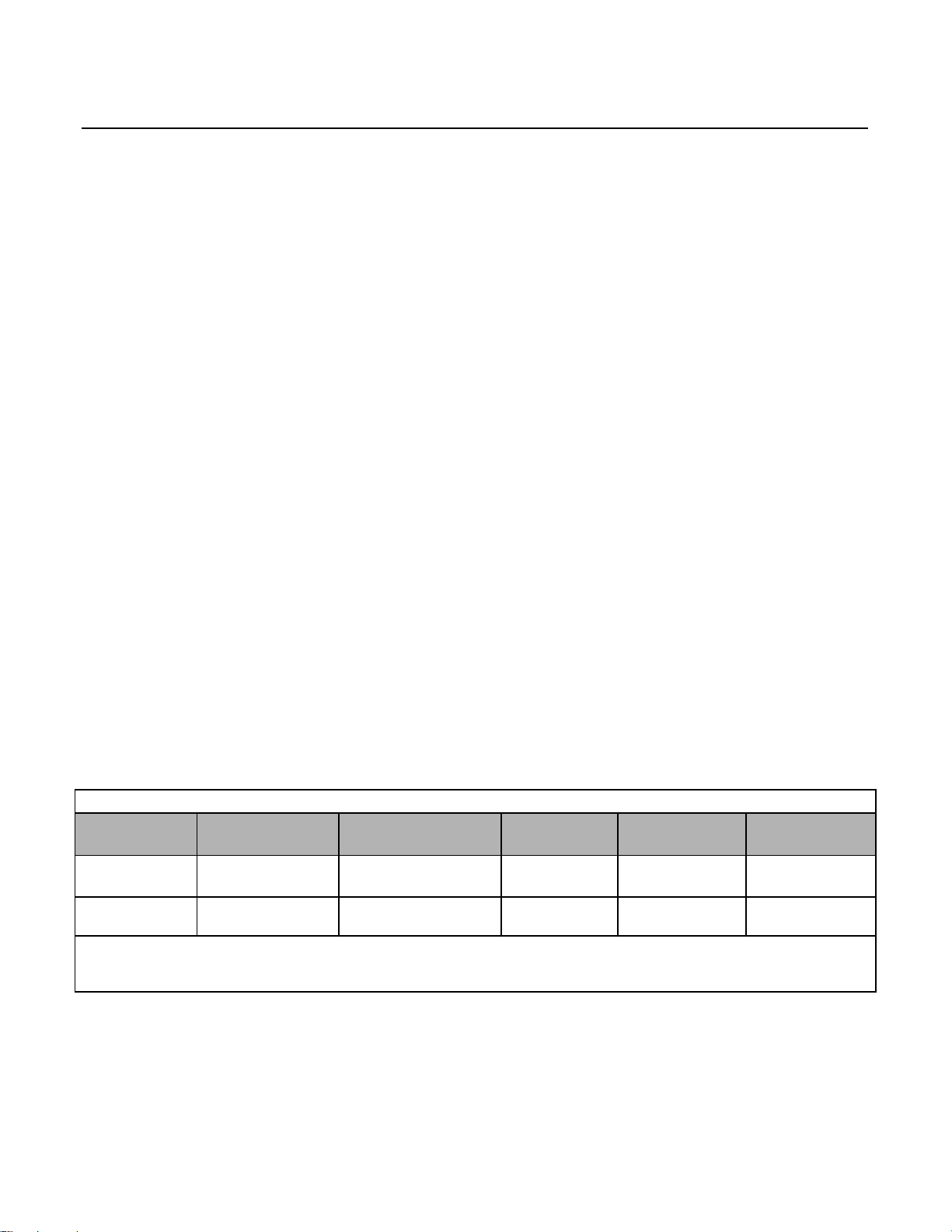
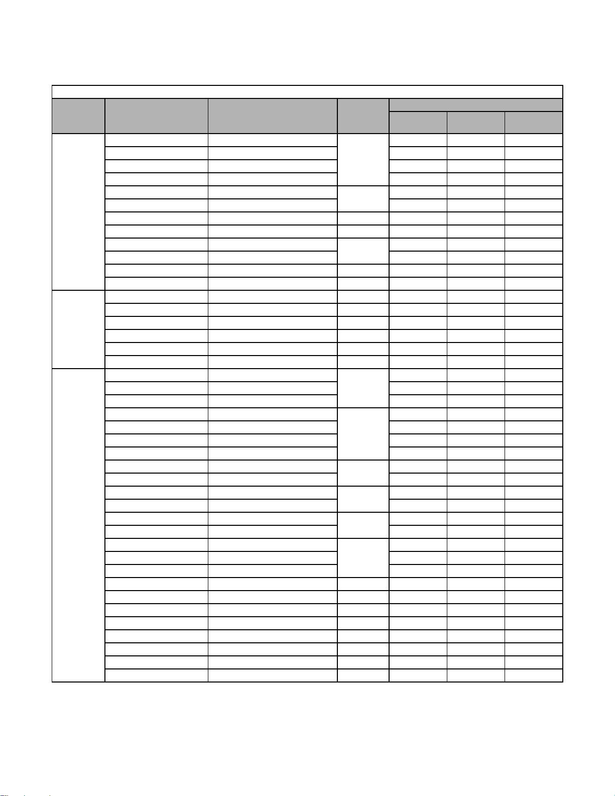
The Drive’s capacity is categorized based on two types of load characteristics: Heavy Duty and Normal Duty. See Table i.1
below for the differences between Heavy Duty and Normal Duty.
Table i.1 Drive Duty Selection
Parameter
C6-01
0: Heavy Duty
(default)
2: Normal Duty
* See Drive Specifications
** Software version VSF103021 and higher allows the carrier frequency to b e in creased while in HD (C6-01=0). The continuous current
and overload are automatically reduced to the levels indicated in Table 5.1.
This manual references the various Drive capacities according to its model number CIMR-F7U
Rated Output
Current
Standard rating
(varies by model*)
Extended rating
(varies by model*)
Overload
Capacity
150% for 1 min. 150%
Approx. 110% for 1 min.
(varies by mode l*)
Current Limit
120%
Carrier
Frequency
Low
(2kHz**)
High
(varies by model*)
FFFF. See Drive
Maximum Output
Frequency
300Hz
400Hz
Output Specifications Table i.2 and Table i.3 on the following pages for rated capacities and Drive specifications.
iii
Page 6
Drive Output Specifications
Output ratings
*1
*1
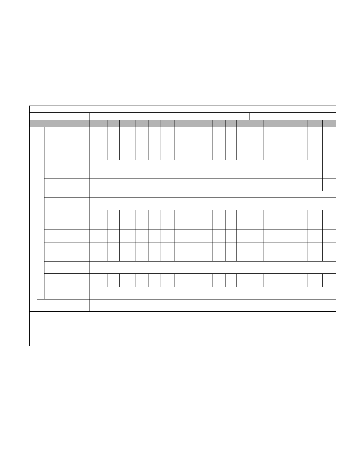
The standard Drive specifications are listed in the following tables.
208-240Vac
Table i.2 208-240Vac Drive Specifications
208-240Vac 208-230Vac
Model Number CIMR-F7U
Rated output
capacity
(kVA)
Horsepower
*2
Rated output
current
(A)
Overload capacity
(% of rated output
current for 60 sec.)
Heavy Duty
Current limit (% of
rated outpu t cu rrent)
Carrier frequency
Maximum output
frequency
Rated output
(kVA)
capacity
Horsepower
*2
Rated output
current
(A)
Overload capacity
(% of rated output
current for 60 sec.)
Current limit (% of
Normal Duty
rated outpu t cu rrent)
Carrier frequency
*5
(kHz)
Maximum output
frequency
Maximum output voltage
*1 The difference between Heavy Duty ratings and the Normal Duty ratings for the Drive are the rated input and output current, overload capacity, carrier frequency, current limit, and
maximum output frequency. Parameter C6-01 must be set to value of “0” for Heavy Duty ratings and “2” for Normal Duty ratings. Factory default is Heavy Duty (C6-01=0).
*2 Horsepower ratings are based on 230V or 460V NEC Table 430.150. The maximum applicable motor output is given for a standard 4-pole motor. When selecting the actual motor
and Drive, be sure that the Drive's rated output current is appropria te for the mot or's rated current.
*3 Model 2110 has an overload rating of 138% of rated outp ut curren t for 60 sec onds and a current limi t rating of 138%. Models 4220 and 4300 have an overload rating of 150% of
rated output current for 45 seconds and a current limit rating of 150%.
*4 Wh en setting the carrier frequency above the factory default, the Drive mus t be derated.
*5 Heavy Duty ratings for models 2110, 4220 and 4300 are effective in software version VSF103021 and higher.
20P4 20P7 21P5 22P2 23P7 25P5 27P5 2011 2015 2018 2022 2030 2037 2045 2055 2075 2090
1.2 1.6 2.7 3.7 5.7 8.8 12.0 17.0 22.0 27.0 32.0 44.0 55.0 69.0 82.0 110.0 130.0 140.0
0.5/0.75 1 2 3 5 7.5 10 15 20 25 30 40 50 60 75 100 125 150
3.2 4.2 7.0 9.6 15.2 23.0 31.0 45.0 58.0 71 85.0 115.0 145.0 180.0 215 283.0 346.0 360.0
*3
150
150
*4
2kHz
300.0Hz
1.4 1.8 3.0 4.1 6.4 8.8 12.0 18.0 23.0 29.0 34.0 44.0 62.0 73.0 82.0 120.0 140.0 160.0
0.5/0.75 1 2 3 5 7.5 10 15 20 25 30 40 50/60 75 75 100/125 150 150
3.6 4.6 7.8 10.8 16.8 23.0 31.0 46.2 59.4 74.8 88.0 115.0 162.0 192.0 215 312.0 360.0 415.0
*3
107 107 108 107 107 120 120 117 117 114 116 120 107 113 120 109 115 120
120
10 1010 81015158101010105 5 8 2 2 2
400.0Hz
3-phase; 200, 208, 220, 230, or 240Vac
(Proportional to input voltage)
2110
138
138
*5
*3
*3
iv
Page 7
Output ratings
*1
*1
Output ratings
*1
*1
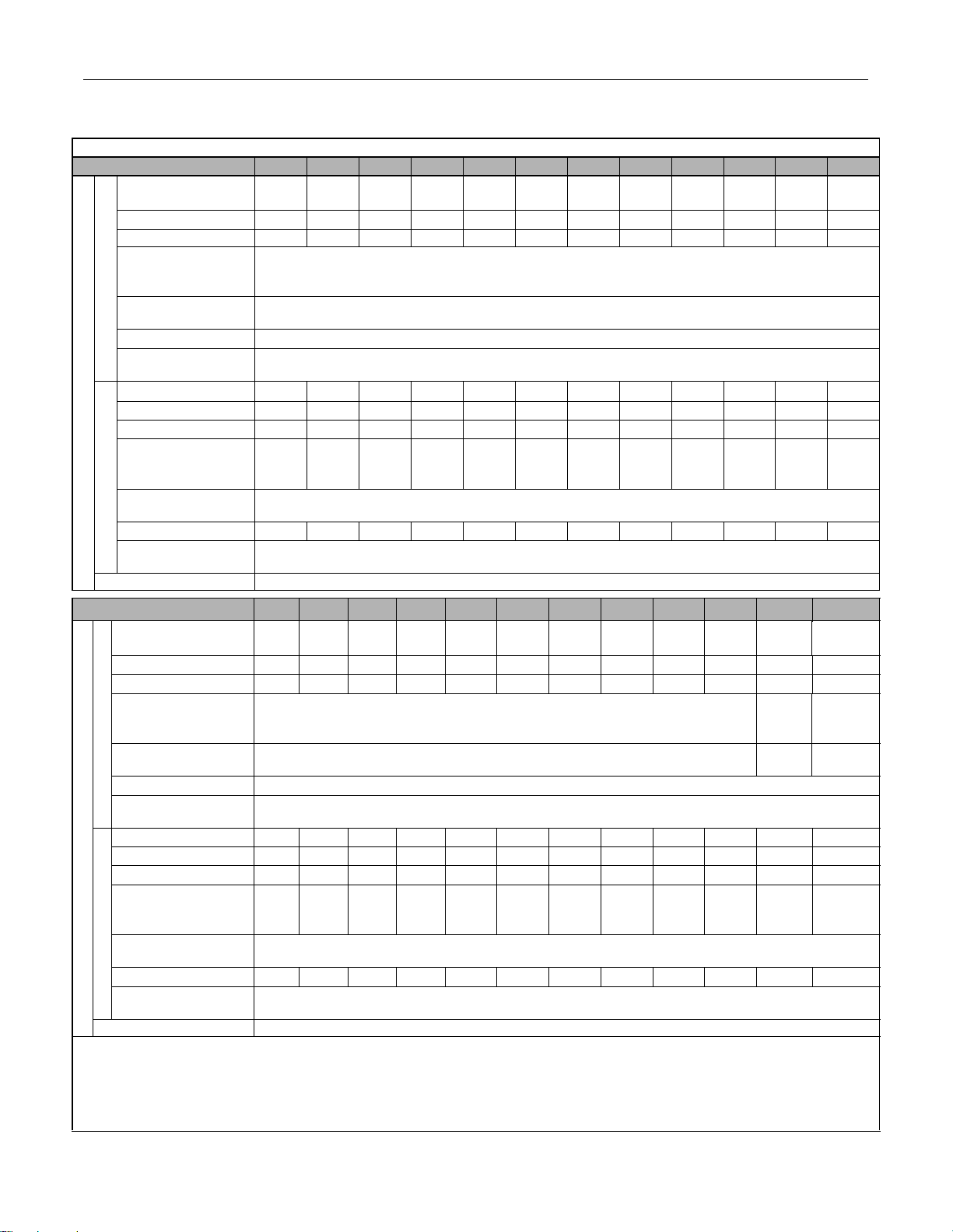
480Vac
Table i.3 480Vac Drive Specifications
Model Number CIMR-F7U 40P4 40P7 41P5 42P2 43P7 44P0 45P5 47P5 4011 4015 4018 4022
Rated output
capacity
(kVA)
Horsepower
*2
Rated output current (A) 1.8 2.1 3.7 5.3 7.6 8.7 12.5 17.0 24.0 31.0 39.0 45.0
Overload capacit y
*3
(% of rated ou tput
current for 60 sec.)
Heavy Duty
Current limit (% of rated
output current)
Carrier frequency
*4
Maximum output
frequency
Rated output capacity
Horsepower
Rated output current
Overload capacit y
(kVA)
*2
(A)
*3
(% of rated ou tput
current for 60 sec.)
Current limit (% of rated
Normal Duty
output current)
Carrier frequency (kHz)
Maximum output
frequency
Maximum output voltage 3-phase; 380, 400, 415, 440, 460, or 480Vac (Proportional to input voltage)
Model Number CIMR-F7U 4030 4037 4045 4055
*4
*3
*3
(A)
(kVA)
(A)
Rated output capacity
(kVA)
Horsepower
*2
Rated outpu t cu rrent
Overload capacity
(% of rated output
current for 60 sec.)
Current limit (% of rated
Heavy Duty
output current)
Carrier frequency
Maximum output
frequency
Rated output capac ity
Horsepower
*2
Rated outpu t cu rrent
Overload capacity
(% of rated output
current for 60 sec.)
Current limit (% of rated
Normal Duty
output current)
Carrier frequency (kHz)
Maximum output
frequency
Maximum output voltage 3-phase, 380, 400, 415, 440, 46 0 or 480Vac (Proportional to input voltage)
*1 The difference between Heavy Duty ratings and the Normal Duty ratings for the Drive are the rated input and output current, overload capacity, carrier frequency, current limit, and
maximum output frequency. Parameter C6-01 must be set to value of “0” for Heavy Duty ratings and “2” for Normal Duty ratings. Factory default is Heavy Duty (C6-01=0).
*2 Horsepower ratings are based on 230V or 460V NEC Table 430.150. The maximum applicable motor output is given for a standard 4-pole motor. When selecting the actual motor
and Drive, be sure that the Drive's rated output current is appropriate for the motor's rated current.
*3 Model 2110 has an overload rating of 138% of rated output current for 60 seconds and a current limit rating of 138%. Models 4220 and 4300 have an overload rating of 150% of
rated output current for 45 seconds and a current limit rating of 150%.
*4 When setting the carrier frequency above the factory default, the Drive must be derated.
*5 Heavy Duty ratings for models 2110, 4220 and 4300 are effective in software version VSF103021 and higher.
1.4 1.6 2.8 4.0 5.8 6.6 9.5 13.0 18.0 24.0 30.0 34.0
0.5/0.75 1 1.5/2 3 5 - 7.5 10 15 20 25 30
150
150
2kHz
300.0Hz
1.4 1.6 2.8 4.0 5.8 6.6 9.5 13.0 21.0 26.0 30.0 38.0
0.5/0.75 1 1.5/2 3 5 - 7.5 10 15/20 25 30 30
1.8 2.1 3.7 5.3 7.6 8.7 12.5 17.0 27.0 34.0 40.0 50.4
120 120 120 120 120 120 120 120 107 109 117 107
120
*5
15 15 15 15 15 15 15 15 8 10 10 10
400.0Hz
4075 4090 4110
4132 4160 4185
4220*54300
46.0 57.0 69.0 85.0 110.0 140.0 160.0 200.0 230.0 280.0 315.0 450.0
40 50 60 75 100 125/150 - 200 250 300 350 500
60.0 75.0 91.0 112.0 150.0 180.0 216.0 260.0 304.0 370.0 414.0 590.0
150
150
150
150
*3
*3
2kHz
300.0Hz
51.0 59.0 73.0 95.0 120.0 140.0 180.0 200.0 230.0 315.0 390.0 510.0
40/50 60 75 100 125 150 200 - 250 300/350 400/450 500+
67.2 77.0 96.0 125.0 156.0 180.0 240.0 260.0 304.0 414.0 515.0 675.0
107 117 114 108 115 120 108 120 120 107 118 120
120
*5
88855855522 2
400.0Hz
v
150
150
*5
*3
*3
Page 8

Notes:
vi
Page 9

Table of Contents
Warnings and Cautions................................................................................................ i
Introduction .................................................................................................................iii
Table of Contents .......................................................................................................vii
Chapter 1- Physical Installation ................................................................................1-1
F7 Model Number, Enclosure, Heat Loss, and Weight ............................................1-2
Confirmations Upon Delivery ...................................................................................1-3
Component Names ..................................................................................................1-5
Exterior and Mounting Dimensions ..........................................................................1-7
Checking and Controlling Installation Site.............................................................. 1-11
Installation Orientation and Clearances .................................................................1-12
Removing and Attaching the Terminal Cover.........................................................1-13
Removing/Attaching the Digital Operator and Front Cover....................................1-14
Chapter 2- Electrical Installation...............................................................................2-1
Terminal Block Configuration ................................................................................... 2-2
Wiring Main Circuit Terminals................................................................................... 2-3
Control Wiring ........................................................................................................2-20
Electromagnetic Compatibility (EMC) ....................................................................2-26
Installing and Wiring Option Boards.......................................................................2-30
Chapter 3- Digital Operator........................................................................................3-1
Digital Operator Display ...........................................................................................3-2
Digital Operator Keys ...............................................................................................3-3
Drive Mode Indicators..............................................................................................3-4
Drive Main Menus ....................................................................................................3-6
Quick Setting Menu (-QUICK-)...............................................................................3-11
Programming Menu (-ADV-)...................................................................................3-12
Example of Changing a Parameter........................................................................3-15
Table of Contents vii
Page 10

Chapter 4- Start-Up.....................................................................................................4-1
Drive Start-Up Preparation ....................................................................................... 4-2
Drive Start-Up Procedures ....................................................................................... 4-5
Chapter 5- Basic Programming................................................................................. 5-1
Description of Parameter Tables.............................................................................. 5-2
Control Method.........................................................................................................5-2
Speed Command Source......................................................................................... 5-3
Run Command Source............................................................................................. 5-4
Stopping Method ..................................................................................................... 5-5
Accel/Decel Time ..................................................................................................... 5-8
Carrier Frequency .................................................................................................... 5-9
Preset Reference ................................................................................................... 5-10
Input Voltage Setting.............................................................................................. 5-11
V/F Pattern ............................................................................................................. 5-11
Motor Setup............................................................................................................ 5-19
PG Option .............................................................................................................. 5-19
Analog Output Gain................................................................................................ 5-20
Motor Overload Fault .............................................................................................5-21
Stall Prevention ...................................................................................................... 5-22
Chapter 6- Diagnostic & Troubleshooting .............................................................. 6-1
Fault Detection ......................................................................................................... 6-2
Alarm Detection........................................................................................................ 6-9
Operator Programming Errors (OPE)..................................................................... 6-13
Auto-Tuning Faults .................................................................................................6-15
Digital Operator COPY Function Faults .................................................................6-17
Troubleshooting ..................................................................................................... 6-18
Main Circuit Test Procedure ...................................................................................6-26
Drive Date Stamp Information ................................................................................ 6-29
Table of Contents viii
Page 11

Chapter 7- Maintenance ............................................................................................. 7-1
Periodic Inspection................................................................................................... 7-2
Preventative Maintenance........................................................................................ 7-3
Periodic Maintenance of Parts ................................................................................. 7-4
Heatsink Cooling Fan Replacement.........................................................................7-5
Removing and Mounting the Terminal Card.............................................................7-7
Appendix A - Parameters.......................................................................................... A-1
F7 Parameter List.....................................................................................................A-3
F7 Monitor List .......................................................................................................A-40
F7 Fault Trace List .................................................................................................A-43
F7 Fault Trace History............................................................................................A-43
Appendix B - Capacity Related Parameters............................................................ B-1
Drive Capacity Selection ..........................................................................................B-2
Parameters Affected by Drive Capacity Setting .......................................................B-3
Appendix C - Specifications ..................................................................................... C-1
Standard Drive Specifications ................................................................................. C-2
Appendix D - Communications ................................................................................ D-1
Using Modbus Communication ............................................................................... D-2
Modbus Function Code Details ............................................................................... D-8
Modbus Data Tables ............................................................................................. D-10
Modbus Self-Diagnosis ......................................................................................... D-18
Table of Contents ix
Page 12

Appendix E - Peripheral Devices ............................................................................. E-1
Branch Circuit Short Circuit Protection.....................................................................E-2
Branch Circuit Overload Protection..........................................................................E-5
Peripheral Devices...................................................................................................E-6
Appendix F - Spare Parts...........................................................................................F-1
F7 Primary Spare Parts - 208/230/240Vac...............................................................F-2
F7 Primary Spare Parts - 480Vac.............................................................................F-3
Index ................................................................................................................. Index-1
Support Services................................................................................ Inside rear cover
Table of Contents x
Page 13

Chapter 1
Physical Installation
This chapter describes the requirements for receiving and installing the F7 Drive.
F7 Model Number, Enclosure, Heat Loss, and Weight. 1-2
Confirmations upon Delivery ........................................ 1-3
Component Names....................................................... 1-5
Exterior and Mounting Dimensions............................... 1-7
Checking and Controlling the Installation Site ............ 1-11
Installation Orientation and Clearances......................1-12
Removing and Attaching the Terminal Cover .............1-13
Removing/Attaching the Digital Operator
and Front Cover.......................................................... 1-14
Physical Installation 1 - 1
Page 14
F7 Model Number, Enclosure, Heat Loss, and Weight
Table 1.1 F7 Model Number and Enclosure Style
Input
Volta ge
3-Phase
208-240V ac
208-230Vac
480 Vac
F7
Model-Number
CIMR- F7U2 0P4 NEMA T ype 1 (IP20)
CIMR-F7U20P 7 NEMA Type 1 (IP20) 26 42 68
CIMR-F7U21P 5 NEMA Type 1 (IP20) 48 50 98
CIMR-F7U22P 2 NEMA Type 1 (IP20) 68 59 127
CIMR- F7U2 3P7 NEMA T ype 1 (IP20)
CIMR-F7U25P5 NEMA Type 1 (IP20) 164 84 248
CIMR-F7U27P5 NEMA Type 1 (IP20) 13.2 (6.0) 219 113 332
CIMR-F7U2011 NEMA Type 1 (IP20) 15.4 (7.0) 357 168 525
CIMR- F7U2 015 NEMA Type 1 (IP20)
CIMR-F7U201 8 NEMA Type 1 (IP20) 472 208 680
CIMR-F7U202 2 NEMA Type 1 (IP20) 53 (2 4) 583 252 835
CIMR-F7U2030 NEMA Type 1 (IP20) 59 (27) 883 333 1216
CIMR-F7U203 7 Open Chassis (IP00) 125 (57) 1010 421 1431
CIMR-F7U204 5 Open Chassis (IP00) 139 (63) 1228 499 1727
CIMR-F7U205 5 Open Chassis (IP00) 189 (86) 1588 619 2207
CIMR-F7U207 5 Open Chassis (IP00) 191 (87) 1956 844 2800
CIMR-F7U2090 Open Chassis (IP00) 238 (108) 2194 964 3158
CIMR-F7U 2110 Open Chassis (IP00) 330 (150) 2733 1234 3967
CIMR- F7U4 0P4 NEMA T ype 1 (IP20)
CIMR-F7U40P 7 NEMA Type 1 (IP20) 17 41 58
CIMR-F7U41P 5 NEMA Type 1 (IP20) 36 48 84
CIMR- F7U4 2P2 NEMA T ype 1 (IP20)
CIMR-F7U43P 7 NEMA Type 1 (IP20) 80 68 148
CIMR-F7U44P 0 NEMA Type 1 (IP20) 90 70 160
CIMR-F7U45P5 NEMA Type 1 (IP20) 127 81 208
CIMR- F7U4 7P5 NEMA T ype 1 (IP20)
CIMR-F7U40 11 NEMA Type 1 (IP20) 232 158 390
CIMR- F7U4 015 NEMA Type 1 (IP20)
CIMR-F7U401 8 NEMA Type 1 (IP20) 389 201 590
CIMR- F7U4 022 NEMA Type 1 (IP20)
CIMR-F7U403 0 NEMA Type 1 (IP20) 691 298 989
CIMR- F7U4 037 NEMA Type 1 (IP20)
CIMR-F7U4045 NEMA Type 1 (IP20) 901 386 1287
CIMR-F7U4055 NEMA Type 1 (IP20) 1204 478 1682
CIMR-F7U407 5 Open Chassis (IP00) 194 (88) 1285 562 1847
CIMR-F7U409 0 Open Chassis (IP00) 196 (89) 1614 673 2287
CIMR-F7U4110 Open Chassis (IP00) 224 (102) 1889 847 2736
CIMR-F7U413 2 Open Chassis (IP00) 265 (120) 2388 1005 3393
CIMR-F7U41 60 Open Chassis (IP00) 352 (160) 2791 1144 3935
CIMR-F7U418 5 Open Chassis (IP00) 572 (259) 2636 1328 3964
CIMR-F7U422 0 Open Chassis (IP00) 616 (279) 3797 1712 5509
CIMR-F7U430 0 Open Chassis (IP00) 891 (404) 5838 2482 8320
Enclosure Style
Weight
lb (kg)
6.6 (3.0)
8.8 (4.0)
24.2 (11.0)
6.6 (3.0)
8.8 (4.0)
13.2 (6.0)
22 (10)
53 (24)
88 (40)
Heatsink Internal To ta l
110 74 184
416 182 598
193 114 307
296 169 465
420 233 653
801 332 1133
Heat Loss (watts)
19 39 58
14 39 53
59 56 115
Physical Installation 1 - 2
Page 15

Confirmations upon Delivery
N
e.
Receiving Checks
Check the following items as soon as the Drive is received.
Table 1.2 Receiving Checks
Item Method
Has the correct model of Drive been delivered?
Check the model number on the nameplate on the right side of the Drive.
Reconcile with packing slip and/or order information.
Is the Drive damaged in any way?
Are any screws or other components loose? Use a screwdriver or other tool to check for tightness.
Inspect the entire exterior of the Drive to see if there are any dents, scratches or other
damage resulting from shipping.
If there are any irregularities in the above items, contact the shipping comp any, or the distributor / representative who sold the
Drive, or a Yaskawa office immediately.
Nameplate Information
A nameplate is attached to the right side of each Drive. The following nameplate is an example for a standard Drive.
Drive Mode l Number
Input Power Rating
Output Power Rating
Serial Number
UL File Number
Drive Spec Number
Weight
Software Number
ote: The Drive Model Number, Drive Spec Number, Software Number, and Serial Number are required to co mpletely identify a Driv
HD - Heavy Duty; ND - Normal Duty
Fig 1.1 F7 Drive Nameplate
Physical Installation 1 - 3
Page 16
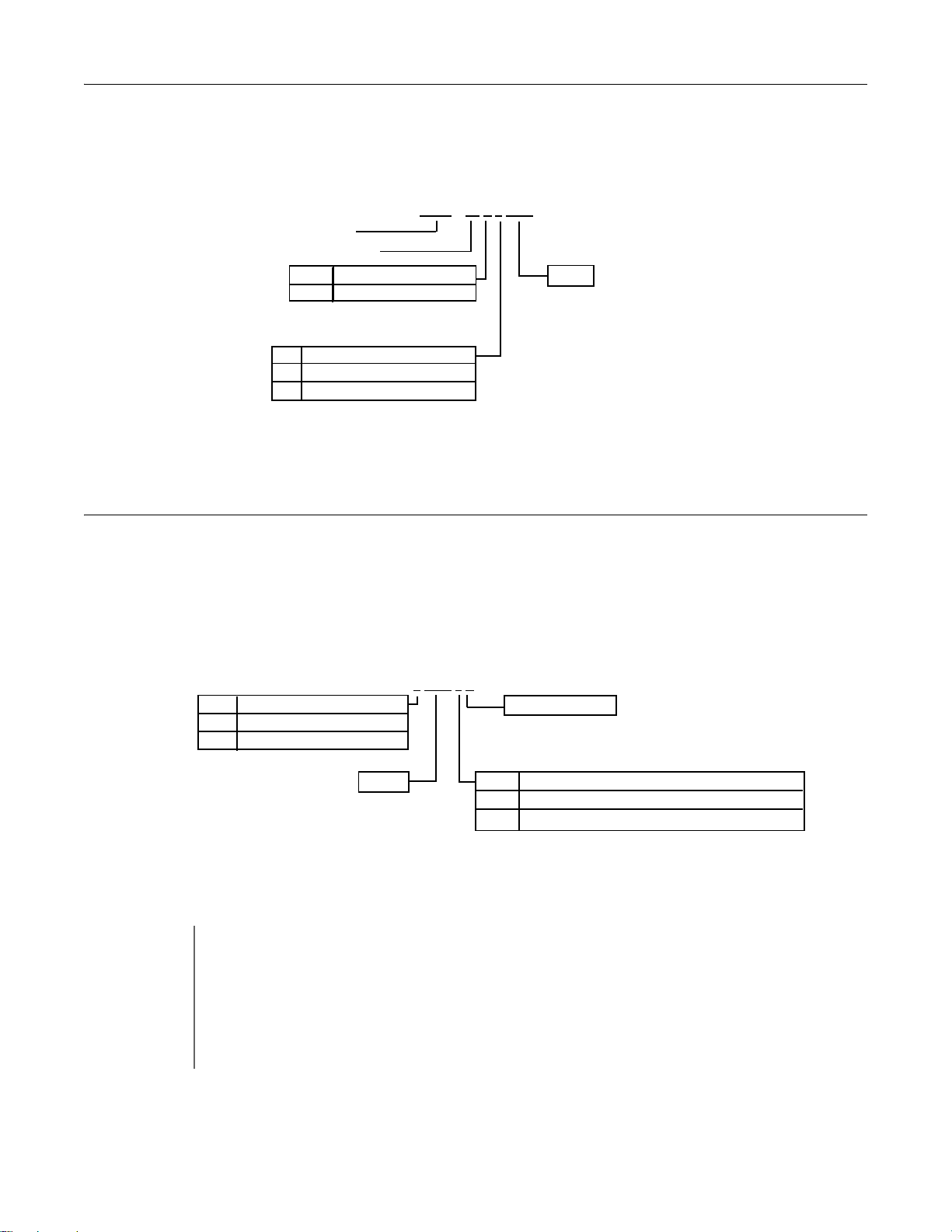
Drive Model Numbers
The model number on the nameplate indicates the design specification, voltage, and rating of the Drive in alphanumeric codes.
CIMR – F7 U 2 0 2 2
AC Drive
F7 Family
No.
U
Spec
UL Specification
Rating
No.
2
4
Voltage
3-phase, 208-240Vac
3-phase, 480Vac
Fig 1.2 Drive Model Number Structure
Drive Enclosure and Revision Code
The SPEC number on the nameplate indicates the voltage, Drive rating, enclosure type, and the revision code of the Drive in
alphanumeric codes. The SPEC number for Drives that have custom features, i.e. CASE software, will have a SPEC number
that indicates the custom features installed.
2
0 2 2 1 E
No.
2
4
Voltage
3-phase, 208 - 240Vac
3-phase, 480Vac
Rating
Hardware Revision
No.
0 Open chassis (IEC IP00)
1
Enclosure Type
NEMA Type 1 (IEC IP20)
TERMS
Fig 1.3 SPEC Number Structure
Open Chassis Type (IEC IP00)
Protected so that parts of the human body cannot reach electrically charged parts from the front when the
Drive is mounted in a control panel, also called protected chassis.
NEMA Type 1 (IEC IP20)
The Drive is shielded from the exterior, and can thus be mounted to the interior wall of a building
(not necessarily enclosed in a control panel). The protective structure conforms to the standards of NEMA 1
in the USA. All protective covers (Fig 1.4 and Fig 1.6) must be installed to conform with IEC IP20 and NEMA
Type 1 requirements.
Physical Installation 1 - 4
Page 17
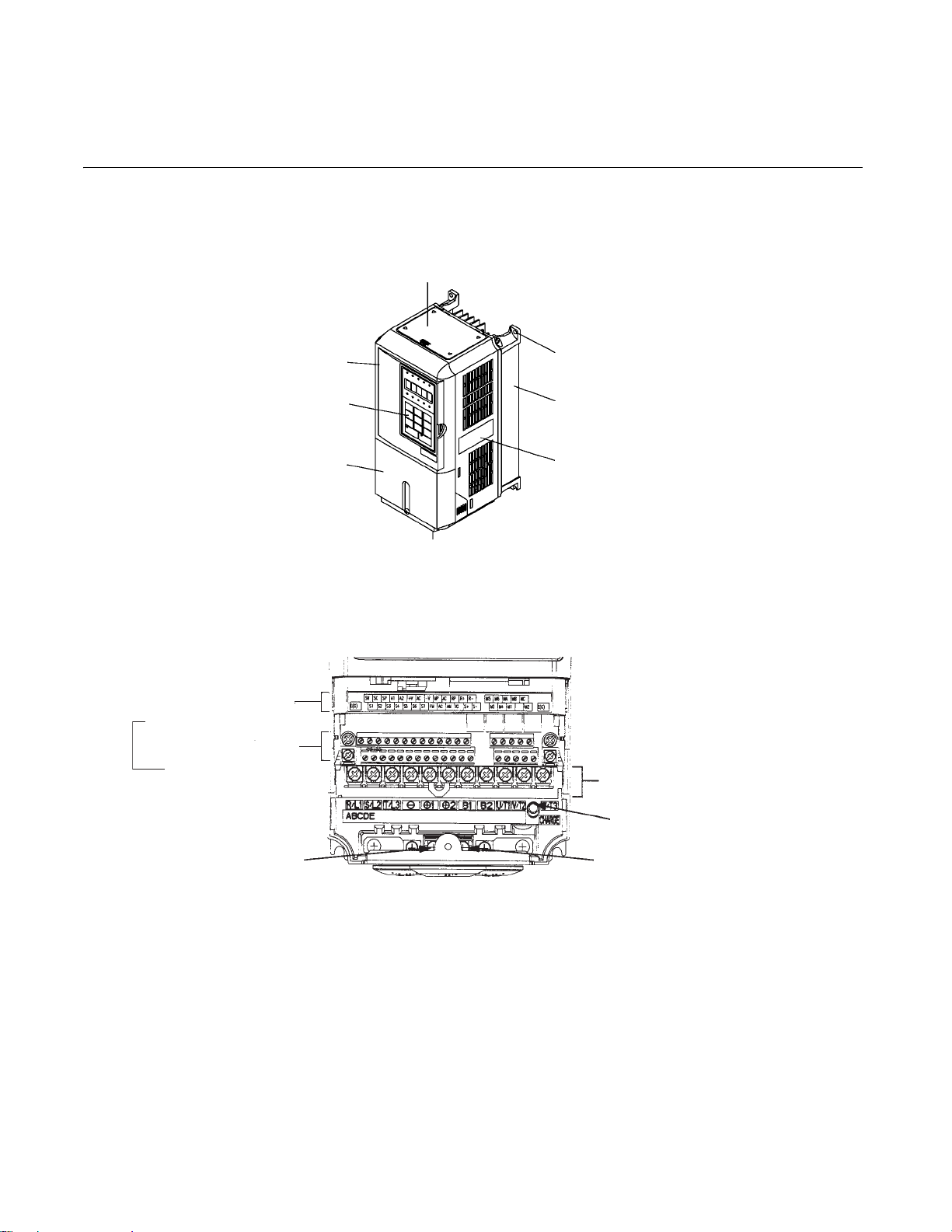
Component Names
Models CIMR-F7U20P4 thru 2018 and 40P4 thru 4018
The external appearance, component names, and terminal arrangement of the Drive are shown in Fig 1.4. and 1.5.
Control circuit terminal
layout label
{
Cont
rol circuit terminals
See Fig. 2.3 for actual
terminal layout
[Required for NEMA Type 1 (IEC IP20)]
Front cover
Digital Operator
Terminal cover
Top protective cover
Mounting hole
Die-cast Heat Sink
Nameplate
Bottom protective cover
Fig 1.4 Drive Appearance
Main circuit terminals
Ground terminal
Charge indicator
Ground terminal
Fig 1.5 Terminal Arrangement (Terminal Cover Removed)
Physical Installation 1 - 5
Page 18
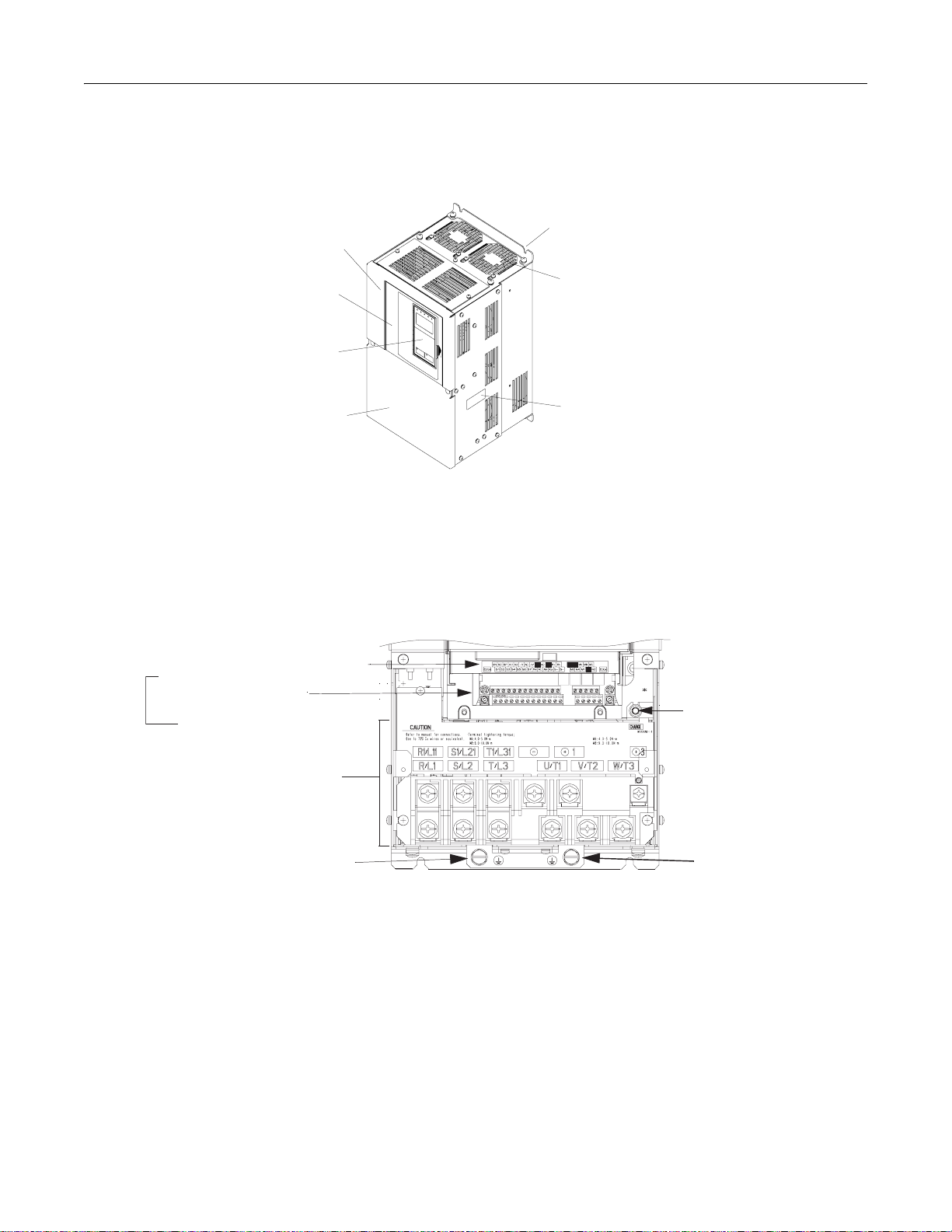
Models CIMR-F7U2022 thru 2110 and 4030 thru 4300
The external appearance, component names, and terminal arrangement of the Drive are shown in Fig 1.6 and 1.7.
Mounting holes
Mounting holes
Drive cover
Drive cover
Cooling fan
Front cover
Front cover
Digital Operator
Digital Operator
Terminal cover
Terminal cover
Fig 1.6 Drive Appearance
Cooling fan
Nameplate
Nameplate
Control circuit terminal layout label
{
Control circuit terminals
See Fig. 2.3 for actual
terminal layout
Main circuit
terminals
Ground terminal
Fig 1.7 Terminal Arrangement (Terminal Cover Removed)
Charge indicator
Ground terminal
Physical Installation 1 - 6
Page 19
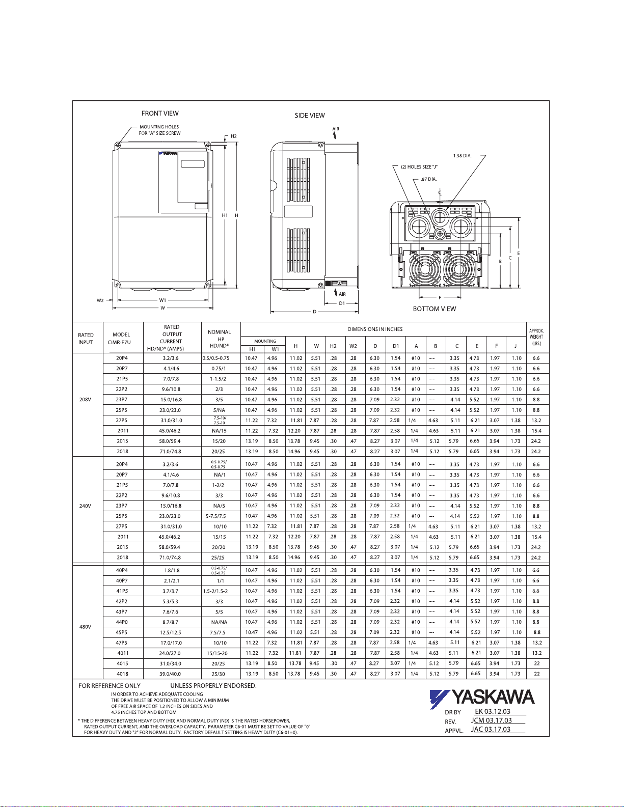
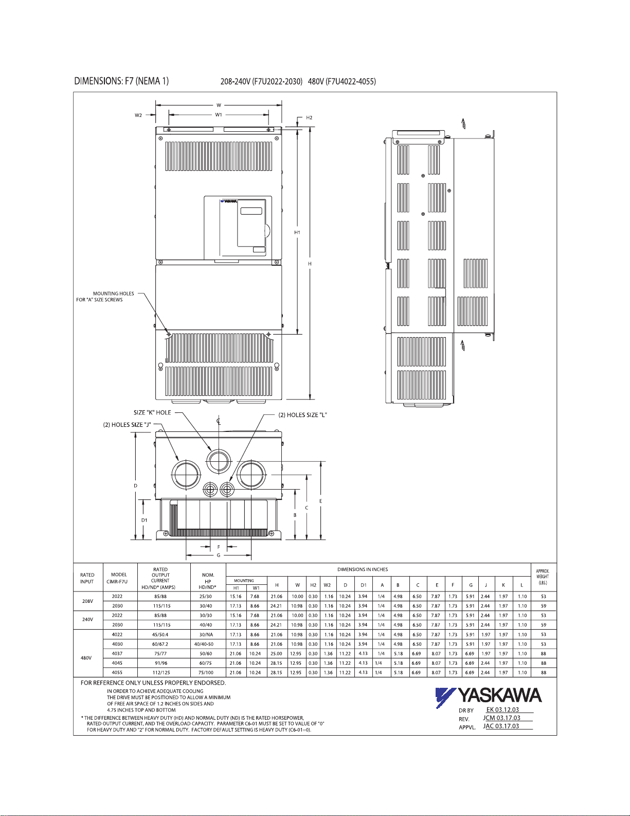
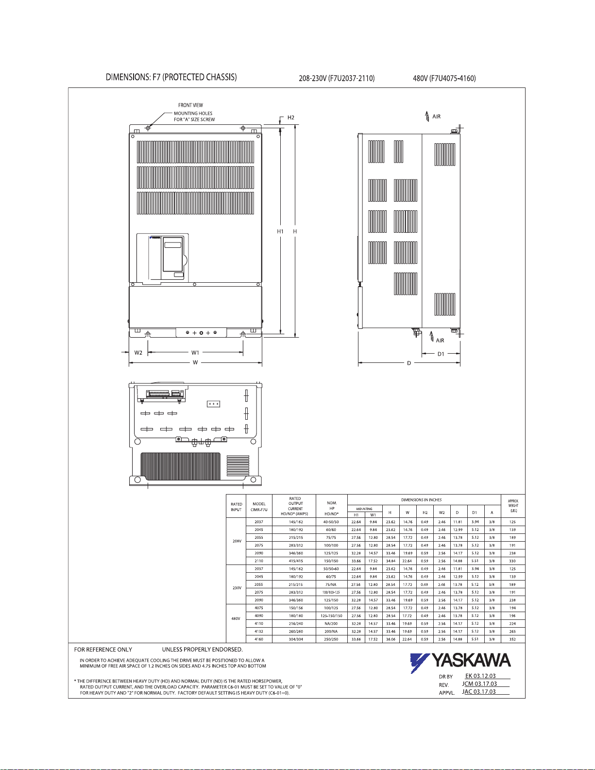
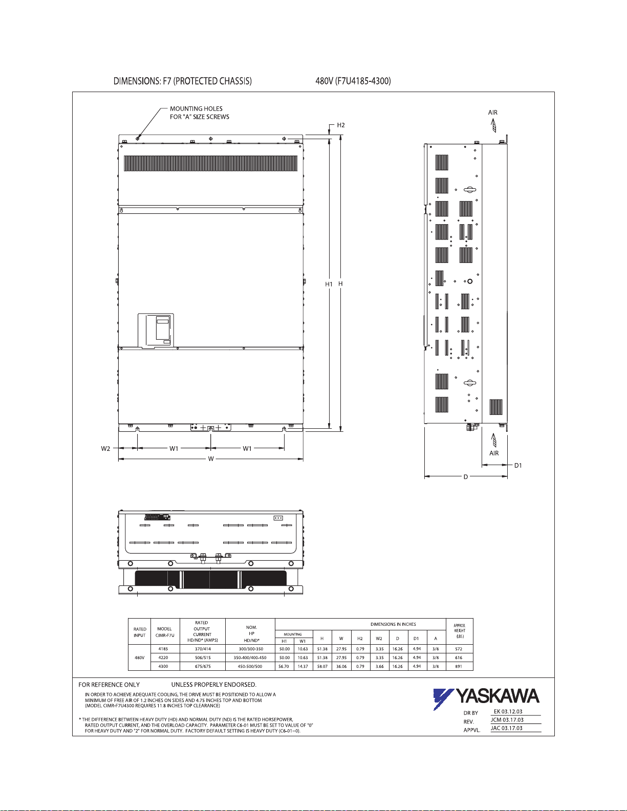
Exterior and Mounting Dimensions
DIMENSIONS: F7 (NEMA 1)
208-240V (F7U20P4-2018) 480V (F7U40P4-4018)
Physical Installation 1 - 7
Page 20
Physical Installation 1 - 8
Page 21
Physical Installation 1 - 9
Page 22
Physical Installation 1 - 10
Page 23

Checking and Controlling the Installation Site
Install the Drive as described below and maintain optimum conditions.
Installation Site
Install the Drive to a non-combustible surface under the following conditions in UL Pollution Degree 2 environments. This
excludes wet locations where pollution may become conductive due to moisture, and locations containing conductive foreign
matter.
Table 1.3 Installation Site Specifications
Type Ambient Operating Temperature Humidity Plenum Rated
NEMA Type 1 14° F -to- 104°F ( - 1 0 -to- + 40 °C) 95%-RH-or-less-(no-condensation) Yes
Open Chassis 14° F -to- 113°F ( - 1 0 - to -+ 45 °C ) 9 5 % -RH-or-less-(no-condensation) No
Protective covers are attached to the top and bottom of the Drive. It is recommended to remove the protective covers before
operating a NEMA Type 1 Drive (Models CIMR-F7U2030/4055 and smaller) in a panel to obtain the 113° (45°C) ambient
operating temperature.
Observe the following precautions when installing the Drive. Make sure to install:
• in a clean location which is free from oil mist and dust.
• in an environment where metal shavings, oil, water, or other foreign materials do not get into the Drive.
• in a location free from radioactive materials and combustible materials (e.g. wood).
• in a location free from harmful gases and liquids.
• in a location free from excessive vibration.
• in a location free from chlorides.
• in a location away from direct sunlight.
Controlling the Ambient Temperature
To enhance the reliability of operation, the Drive should be installed in an environment free from extreme temperature
variation. If the Drive is installed in an enclosure, use a cooling fan or air conditioner to maintain the internal air temperature
below 113°
F (45°C).
Protecting the Drive from Foreign Matter
During Drive installation and project construction, it is possible to have foreign matter such as metal shavings or wire
clippings fall inside the Drive. To prevent foreign matter from falling into the Drive, place a temporary cover over the Drive.
Always remove the temporary cover from the Drive before start-up. Otherwise, ventilation will be reduced, causing the Drive
to overheat.
Physical Installation 1 - 11
Page 24
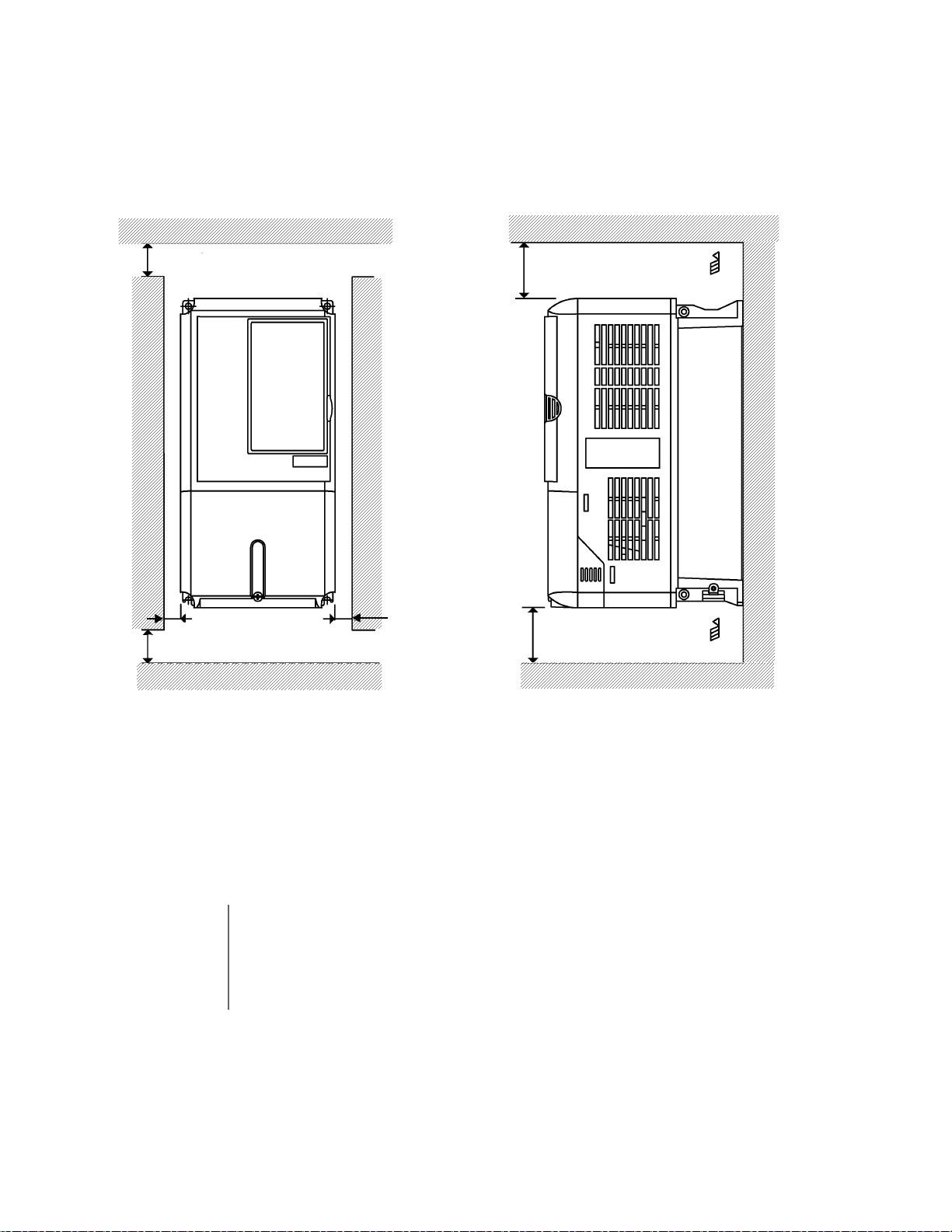
Installation Orientation and Clearances
Install the Drive vertically so as not to reduce the cooling efficiency. When installing the Drive, always provide the following
installation clearances to allow normal heat dissipation and air flow. Ensure that the heatsink is against a closed surface to
avoid diverting cooling air around the heatsink.
1
1.97in *
(50mm) minimum
4.75in *2 (120mm) minimum
Air
1.2in
(30.5mm) minimum
1.97in (50mm) minimum
*1For Drive models F7U2110, F7U4160, and F7U4220, this clearance dimension is 4.75in (120mm) minimum.
For Drive model F7U4300, this clearance dimension is 11.8in (300mm) minimum.
All other models require 1.97in (50mm) minimum.
2
For Drive model F7U4300, this clearance dimension is 11.8in (300mm) minimum. All other models require 4.75in (120mm) minimum.
*
1.2in
(30.5mm) minimum
4.75in (120mm) minimum
Air
Vertical ClearanceHorizontal Clearance
Fig 1.8 Drive Installation Orientation and Clearance
1. The same clearance is required horizontally and vertically for both Open Chassis (IP00)
IMPORTANT
and NEMA Type 1 Drives.
2. Always remove the top and bottom protection covers before installing a CIMR-F7U2018/
4018 and smaller Drive in a panel.
3. Always provide enough clearance for lifting eye bolts and the main circuit wiring when
installing a CIMR-F7U2022/4030 and larger Drive in a panel.
Physical Installation 1 - 12
Page 25
Removing and Attaching the Terminal Cover
Remove the terminal cover to connect cables to the control circuit and main circuit terminals.
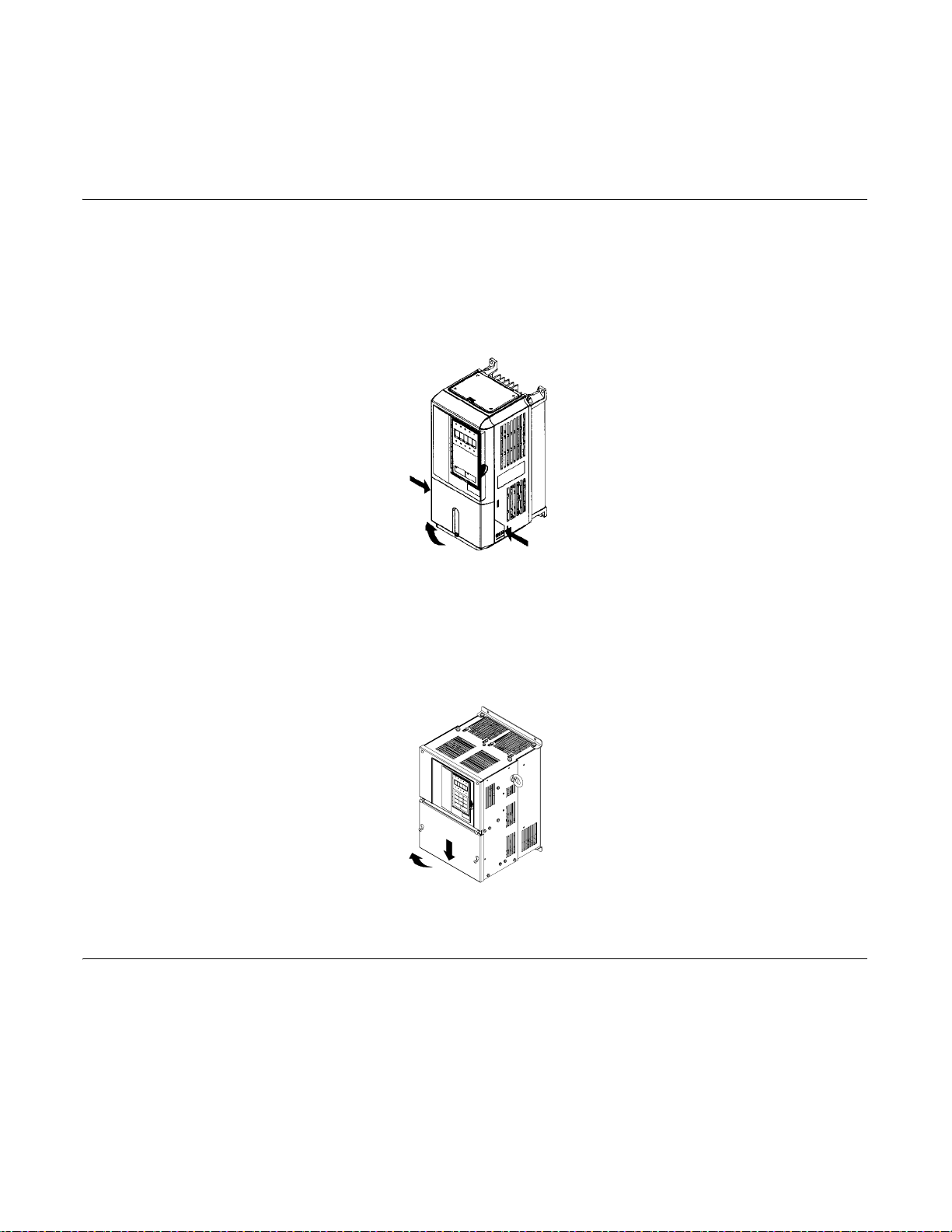
Removing the Terminal Cover
Models CIMR-F7U20P4 thru 2018 and 40P4 thru 4018
Loosen the screw at the bottom of th e termin al cove r, press in on the sid es of the terminal cover in th e directio ns of arrow s 1,
and then lift up on the terminal in the direction of arrow 2.
1
2
1
Fig 1.9 Removing the Terminal Cover
Models CIMR-F7U2022 thru 2110 and 4030 thru 4300
Loosen the screws on the left and right at the top of the terminal cover, pull down the terminal cover in the direction of arrow
1, and then lift up on the terminal cover in the direction of arrow 2.
1
2
Fig 1.10 Removing the Terminal Cover
Attaching the Terminal Cover
After wiring the terminal block, attach the terminal cover by reversing the removal procedure.
For Models CIMR-F7U2018/4018 and smaller, insert the tab on the top of the terminal cover into the groove on the Drive, and
press in on the bottom of the terminal cover until it clicks into place.
For Drives CIMR-F7U2022/4030 and larger, insert the tab on the top of the terminal cover into the groove on the Drive, and
secure the terminal cover by lifting it up toward the top of the Drive.
Physical Installation 1 - 13
Page 26
Removing/Attaching the Digital Operator and Front Cover
Models CIMR-F7U20P4 thru 2018 and 40P4 thru 4018
For Models CIMR-F7U2018/4018 and smaller, remove the terminal cover and then use the following procedures to remove
the Digital Operator and front cover.
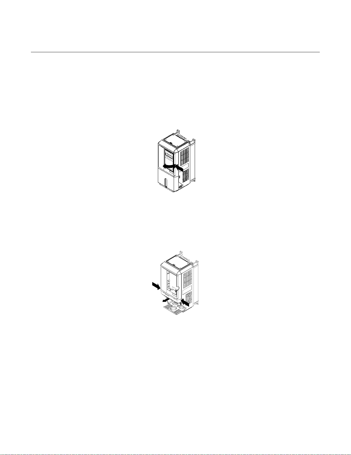
Removing the Digital Operator
Press on the side of the Digital Operator in the direction of arrow 1 to unlock, then li ft the Digital Operato r in the direction of
arrow 2 to remove it as shown in Fig 1.11.
2
Fig 1.11 Removing the Digital Operator
1
Removing the Front Cover
Press the left and right s ides of th e fr ont co ver in t he di recti on of arrows 1 and lift the bottom of cover in t he d irect ion o f ar row
2 to remove it as shown in Fig 1.12.
1
2
Fig 1.12 Removing the Front Cover
1
Mounting the Front Cover
Mount the front cover to the Drive by performing the steps to remove the front cover in reverse order.
1.Do not mount the front cover with the Digital Operator attached as this may cause the Digital Operator to malfunction due to
improper mating with its connector.
2.Insert the tab of the upper part of the front cover into the groove of the Drive and press the lower part of the front cover onto
the Drive until it snaps into place.
Physical Installation 1 - 14
Page 27
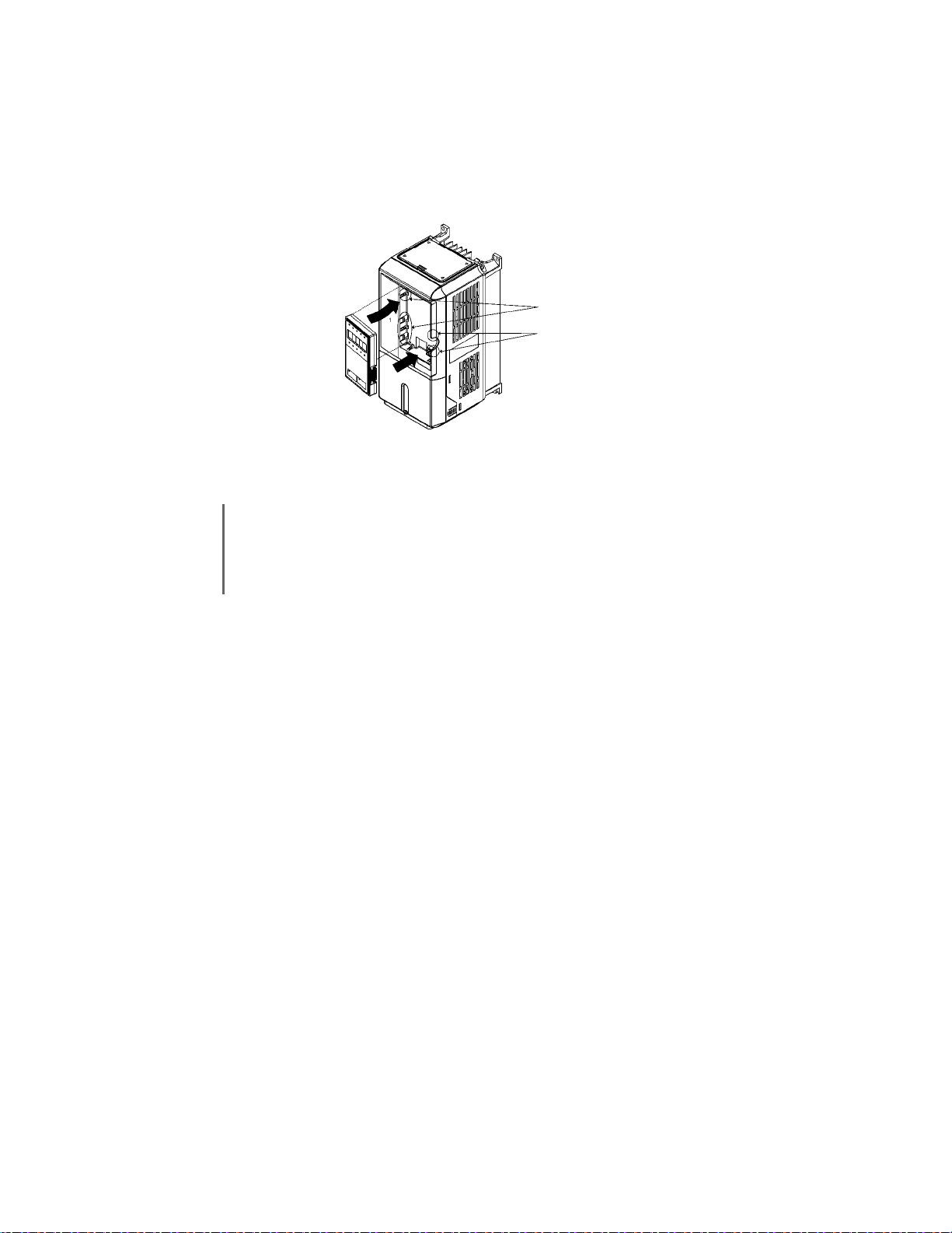
Mounting the Digital Operator
After attaching the front cover, mount the Digital Operator onto the Drive using the following procedure:
1.Hook the Dig ital Operator at A (two locations) on the left side of the opening on the front cover by moving in the direction
of arrow 1 as shown in the following illustration.
2.Press the Digital Operator in the direction of arrow 2 until it snaps in place at B (two locations).
A
IMPORTANT
1
2
Fig 1.13 Mounting the Digital Operator
1. Do not remove or attach the Digital Operator and do not mount or remove the front cover using methods
other than those described above, or damage to the Digital Operator or Drive may occur.
2. Never attach the front cover to the Drive with the Digital Operator already attached. Damage to the Digital
Operator may occur. Always attach the front cover to the Drive first, and then attach the Digital Operator
to the front cover.
B
Physical Installation 1 - 15
Page 28

Models CIMR-F7U2022 thru 2110 and 4030 thru 4300
For Models CIMR-F7U2022/4030 and larger, remove the terminal cover and then use the following procedures to remove the
Digital Operator and front cover.
Removing the Digital Operator
Use the same procedure for Models CIMR-F7U20P4 thru 2018 and 40P4 thru 4018.
Removing the Front Cover
Loosen all screws on the front cover. Lift up at the location labelled 1 at the top of the control circui t termin al card an d move
in the direction of arrow 2.
2
1
Fig 1.14 Removing the Front Cover
Mounting the Front Cover
Attach the front cover by reversing the procedure to remove it.
1. Confirm that the Digital Operator is not mounted o n the front cover. If the cover is attached while the Digital Operator is
mounted to it, the Digital Operator may malfunction due to improper mating with its connector.
2. Insert the tab on the top of the front cover into the slot on the Drive and press in on the cover until it clicks into place on the
Drive.
Mounting the Digital Operator
Use the same procedure for Models CIMR-F7U20P4 thru 2018 and 40P4 thru 4018.
Physical Installation 1 - 16
Page 29

Chapter 2
Electrical Installation
This chapter describes wiring terminals, main circuit terminal connections, main
circuit terminal wiring specifications, control circuit terminals, and control circuit
wiring specifications.
Terminal Block Configuration .............................................2-2
Wiring Main Circuit Terminals............................................ 2-3
Control Wiring ................................................................. 2-20
Electromagnetic Compatibility (EMC)...............................2-26
Installing and Wiring Option Boards .................................2-30
Electrical Installation 2 - 1
Page 30
Terminal Block Configuration
The wiring terminals are shown in Fig 2.1, Fig 2.2 and Fig 2.3.
Control circuit terminal layout label
Control circuit terminals
See Fig. 2.3 below for
actual terminal layout
Ground terminal
Control circuit terminal
layout label
Control circuit terminals
See Fig. 2.3 below for
actual terminal layout
Ground terminal
Main circuit terminals
Charge indicator
Ground terminal
Fig 2.1 Terminal Configuration for Models CIMR-F7U2018/4018 and smaller
Charge indicator
E(G)
Main circuit terminals
Ground terminal
Ground terminal
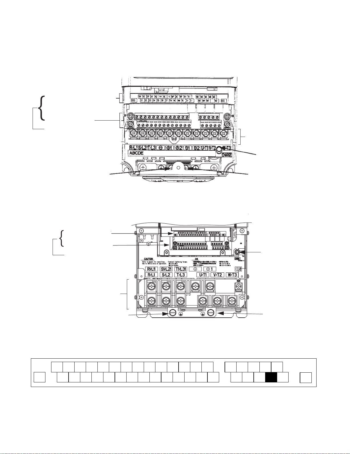
Fig 2.2 Terminal Configuration for Models CIMR-F7U2022/4022 and larger
SN SC SP A1 A2 +V AC -V A3 MP AC RP R+ R- MCM5 M6 MA MB
S1 S2 S3 S4 S5 S6 S7 S8 FM AC AM IG S+ S- M2M3 M4 M1
Fig 2.3 Control Circuit Terminal Layout
Electrical Installation 2 - 2
E(G)
Page 31

Wiring Main Circuit Terminals
Applicable Wire Sizes and Closed-loop Connectors
Select the appropriate wires and crimp terminals from Table 2.1 and Table 2.2. Refer to instruction manual TOE-C726-2 for
Braking Resistor Unit and Braking Unit wire sizes.
Table 2.1 208-240Vac Wire Sizes and Connector Specifications
Drive Model
CIMR-F7U
20P4
Terminal Symbol
R/L1, S/L2, T/L3, , 1, 2, B1, B2
U/T1, V/T2, W/T3 M4
Te rm i na l
Screws
Clamping
To rq u e
lb. in.
(N•m)
10.6 to 13.2
(1.2 to 1.5)
Possible Wire
Sizes AWG
(mm
*1
14 to 10
(2 to 5.5)
2
)
Recommended
Wire Size AWG
2
)
(mm
*2
14
(2)
Wire
Type
20P7
21P5
22P2
23P7
25P5
27P5
2011
2015
2018
2022
2030
R/L1, S/L2, T/L3, , 1, 2, B1, B2
R/L1, S/L2, T/L3, , 1, 2, B1, B2
R/L1, S/L2, T/L3, , 1, 2, B1, B2
R/L1, S/L2, T/L3, , 1, 2, B1, B2
R/L1, S/L2, T/L3, , 1, 2, B1, B2
R/L1, S/L2, T/L3, , 1, 2, B1, B2
R/L1, S/L2, T/L3, , 1, 2, B1, B2
R/L1, S/L2, T/L3, , 1, R1/L11, S1/L21, T1/L31
U/T1, V/T2, W/T3
U/T1, V/T2, W/T3 M4
U/T1, V/T2, W/T3
U/T1, V/T2, W/T3
U/T1, V/T2, W/T3 M4
U/T1, V/T2, W/T3
U/T1, V/T2, W/T3
R/L1, S/L2, T/L3, , 1, 2
U/T1, V/T2, W/T3
B1, B2 M5
R/L1, S/L2, T/L3, , 1, 2
U/T1, V/T2, W/T3
B1, B2 M5
U/T1, V/T2, W/T3,
3
R/L1, S/L2, T/L3, , 1 U/T1,
V/T2, W/T3, R 1 /L11, S1/L21, T1/L31
3
M4
M4
M4
M5
M5
M6
M6
M8
M6
M8
M6
M8
M8
M6
M8
10.6 to 13.2
(1.2 to 1.5)
10.6 to 13.2
(1.2 to 1.5)
10.6 to 13.2
(1.2 to 1.5)
10.6 to 13.2
(1.2 to 1.5)
10.6 to 13.2
(1.2 to 1.5)
21.99
(2.5)
21.99
(2.5)
35.2 to 43.99
(4.0 to 5.0)
21.99
(2.5)
35.2 to 43.99
(4.0 to 5.0)
79.2 to 87.97
(9.0 to 10.0)
21.99
(2.5)
35.2 to 43.99
(4.0 to 5.0)
79.2 to 87.97
(9.0 to 10.0)
35.2 to 43.99
(4.0 to 5.0)
79.2 to 87.97
(9.0 to 10.0)
79.2 to 87.97
(9.0 to 10.0)
35.2 to 43.99
(4.0 to 5.0)
79.2 to 87.97
(9.0 to 10.0)
14 to 10
(2 to 5.5)
14 to 10
(2 to 5.5)
14 to 10
(2 to 5.5)
12 to 10
(3.5 to 5.5)
12 to 10
(3.5 to 5.5)
8 to 6
(8 to 14)
6 to 4
(14 to 22)
4 to 2
(22 to 38)
8 to 6
(8 to 14)
4
(22)
3 to 2
(30 to 38)
8 to 6
(8 to 14)
4
(22)
N/A
N/A
N/A
N/A
N/A
N/A
14
(2)
14
(2)
14
(2)
12
(3.5)
10
(5.5)
8
(8)
4
(22)
6
(14)
3
(30)
4
(22)
Application
Dependent
4
(22)
2
(38)
3
(30)
Application
Dependent
4
(22)
1
(50)
2
(38)
Application
Dependent
4
(22)
1/0
(60)
Application
Dependent
4
(22)
600Vac
UL Approved
vinyl-sheathed
or equivalent
Electrical Installation 2 - 3
Page 32

Table 2.1 208-240Vac Wire Sizes and Connector Specifications (Continued)
Drive Model
CIMR-F7U
2037
2045
2055
2075
2090
2110
Terminal Symbol
R/L1, S/L2, T/L3, , 1 U/T1,
V/T2, W/T3, R1 / L11, S1/L21, T1/L31
3
r/
l1, s/l2
R/L1, S/L2, T/L3, , 1, R1/L11 , S1 /L21, T1/L31
U/T1, V/T2, W/T3
3
r/
l1, s/l2
R/L1, S/L2, T/L3, , 1, U/T1, V/T2, W/T3,
R/L1, S/L2, T/L3, , 1, R1/L11 , S1 /L21, T1/L31
R/L1, S/L2, T/L3, , 1, R1/L11 , S1 /L21, T1/L31
R1/L11, S1/L21, T1/L31
3
r/
l1, s/l2
R/L1, S/L2, T/L3, R1/L11, S1/L21, T1 /L31
U/T1, V/T2, W/T3 N/A
, 1
3
r/
l1, s/l2
U/T1, V/T2, W/T3 N/A
3
r/
l1, s/l2
U/T1, V/T2, W/T3 N/A
3
r/
l1, s/l2
Te rm i na l
Screws
M10
M8
M10
M4
M10
M8
M10
M4
M10
M8
M10
M4
M10
M12
M8
M12
M4
M12
M8
M12
M4
M12
M8
M12
M4
Clamping
To rq u e
lb. in.
(N•m)
154.8 to 197.9
(17.6 to 22.5)
77.4 to 95.0
(8.8 to 10.8)
154.8 to 197.9
(17.6 to 22.5)
11.4 to 12.3
(1.3 to 1.4)
154.8 to 197.9
(17.6 to 22.5)
77.4 to 95.0
(8.8 to 10.8)
154.8 to 197.9
(17.6 to 22.5)
11.4 to 12.3
(1.3 to 1.4)
154.8 to 197.9
(17.6 to 22.5)
77.4 to 95.0
(8.8 to 10.8)
154.8 to 197.9
(17.6 to 22.5)
11.4 to 12.3
(1.3 to 1.4)
154.8 to 197.9
(17.6 to 22.5)
276.2 to 344.8
(31.4 to 39.2)
77.4 to 95.0
(8.8 to 10.8)
276.2 to 344.8
(31.4 to 39.2)
11.4 to 12.3
(1.3 to 1.4)
276.2 to 344.8
(31.4 to 39.2)
77.4 to 95.0
(8.8 to 10.8)
276.2 to 344.8
(31.4 to 39.2)
11.4 to 12.3
(1.3 to 1.4)
276.2 to 344.8
(31.4 to 39.2)
77.4 to 95.0
(8.8 to 10.8)
276.2 to 344.8
(31.4 to 39.2)
11.4 to 12.3
(1.3 to 1.4)
Possible Wire
Sizes AWG
(mm
*1
N/A
N/A
N/A
N/A
N/A
N/A
N/A
N/A
N/A
N/A
N/A
N/A
N/A
N/A
N/A
N/A
N/A
N/A
N/A
N/A
N/A
N/A
N/A
N/A
N/A
*1 Wire size range provided for Drives using insulated screw-type terminal blocks. All other models require the use of UL listed connectors. Refer to Table 2.3.
*2 Recommended wire sizes are based on the normal duty (ND) current ratings and NEC Article 310 Table 310.16, 75 degree Celsius copper or equivalent.
When sizing wiring based on th e heavy duty (HD) current rating s, consul t NEC Article 430 and any other ap pli cable codes.
2
)
Recommended
Wire Size AWG
2
)
(mm
*2
4/0
(100)
Application
Dependent
2
(38)
16
(1.25)
300
(150)
250
(125)
Application
Dependent
1
(50)
16
(1.25)
1/0 X 2P
(60 X 2P)
Application
Dependent
1/0
(60)
16
(1.25)
4/0 X 2P
(100 X 2P)
3/0 X 2P
(80 X 2P)
3/0 X 2P
(80 X 2P)
Application
Dependent
3/0
(80)
16
(1.25)
250 X 2P
(125 X 2P)
4/0 X 2P
(100 X 2P)
Application
Dependent
2/0 X 2P
(70 X 2P)
16
(1.25)
350 X 2P
(200 X 2P)
300 X 2P
(150 X 2P)
Application
Dependent
300 X 2P
(150 X 2P)
16
(1.25)
Wire
Type
600V ac
UL Approved
vinyl-sheathed
or equivalent
Electrical Installation 2 - 4
Page 33

Drive Model
CIMR-F7U
40P4
Table 2.2 480Vac Wire Sizes and Connector Specifications
Ter m i n a l S y mb o l
R/L1, S/L2, T/L3, , 1, 2, B1, B2
U/T1, V/T2, W/T3
Terminal
Screws
M4
Clamping
To rq u e
lb. in.
(N•m)
10.6 to 13.2
(1.2 to 1.5)
Possible Wire
Sizes AWG
2)
(mm
*
1
14 to 10
(2 to 5.5)
Recommended
Wire Size AWG
2
)
(mm
*2
14
(2)
Wire Type
40P7
41P5
42P2
43P7
44P0
45P5
47P5
4011
R/L1, S/L2, T/L3, , 1, 2, B1, B2
U/T1, V/T2, W/T3
R/L1, S/L2, T/L3, , 1, 2, B1, B2
U/T1, V/T2, W/T3
R/L1, S/L2, T/L3, , 1, 2, B1, B2
U/T1, V/T2, W/T3
R/L1, S/L2, T/L3, , 1, 2, B1, B2
U/T1, V/T2, W/T3
R/L1, S/L2, T/L3, , 1, 2, B1, B2
U/T1, V/T2, W/T3
R/L1, S/L2, T/L3, , 1, 2, B1, B2
U/T1, V/T2, W/T3
R/L1, S/L2, T/L3, , 1, 2, B1, B2
U/T1, V/T2, W/T3
M4
M4
M4
M4
M4
M4
M5
10.6 to 13.2
(1.2 to 1.5)
10.6 to 13.2
(1.2 to 1.5)
10.6 to 13.2
(1.2 to 1.5)
10.6 to 13.2
(1.2 to 1.5)
10.6 to 13.2
(1.2 to 1.5)
15.6
(1.8)
21.99
(2.5)
14 to 10
(2 to 5.5)
14 to 10
(2 to 5.5)
14 to 10
(2 to 5.5)
14 to 10
(2 to 5.5)
12 to 10
(3.5 to 5.5)
14 to 10
(2 to 5.5)
10
(5.5)
12 to 10
(3.5 to 5.5)
10 to 6
(5.5 to 14)
14
(2)
14
(2)
14
(2)
12
(3.5)
14
(2)
12
(3.5)
14
(2)
10
(5.5)
12
(3.5)
8
(8)
10
(5.5)
600Vac
UL Approved
vinyl-sheathed
or equivalent
4015
4018
4022
R/L1, S/L2, T/L3, , 1, 2,B1, B2
U/T1, V/T2, W/T3
R/L1, S/L2, T/L3, , 1, 2
U/T1, V/T2, W/T3
B1, B2 M5
R/L1, S/L2, T/L3, , 1, 3, R1/L11, S1/L21,
T1/L31
U/T1, V/T2, W/T3
Electrical Installation 2 - 5
M5
M5 21.99
M6
M6
M6
M6
M8
21.99
(2.5)
(2.5)
35.2 to 43.99
(4.0 to 5.0)
35.2 to 43.99
(4.0 to 5.0)
21.99
(2.5)
35.2 to 43.99
(4.0 to 5.0)
35.2 to 43.99
(4.0 to 5.0)
79.2 to 87.97
(9.0 to 10.0)
8 to 6
(8 to 14)
10 to 6
(5.5 to 14)
8 to 2
(8 to 38)
8
(8)
8 to 4
(8 to 22)
N/A
N/A
8
(8)
10
(5.5)
6
(14)
8
(8)
8
(8)
8
(8)
4
(22)
6
(14)
6
(14)
Page 34

Drive Model
CIMR-F7U
4030
4037
4045
4055
4075
4090
4110
Table 2.2 480Vac Wire Sizes and Connector Specifications (Continued)
Terminal Symbol
R/L1, S/L2, T/L3, , 1, 3, R1/L11, S1/L21,
R/L1, S/L2, T/L3, , 1, R1/L11, S1/L21, T1/L31
R/L1, S/L2, T/L3, , 1, R1/L11, S1/L21, T1/L31
R/L1, S/L2, T/L3, , 1, U/T1, V/T2,
W/T3, R1/L11, S1/L21, T1/L31
R/L1, S/L2, T/L3, , 1, R1/L11, S1/L21, T1/L31
R/L1, S/L2, T/L3, , 1, R1/L11, S1/L21, T1/L31
R/L1, S/L2, T/L3, , 1, R1/L11, S1/L21, T1/L33
T1/L31
U/T1, V/T2, W/T3
U/T1, V/T2, W/T3
3
U/T1, V/T2, W/T3
3
3
U/T1, V/T2, W/T3 N/A
3
r/
l1, s200/l
200, s400/l2400 M4
2
U/T1, V/T2, W/T3 N/A
3
r/
l1, s200/l
200, s400/l2400 M4
2
U/T1, V/T2, W/T3 N/A
3
r/
l1, s200/l
200, s400/l2400 M4
2
Te rm i na l
Screws
M6
M8
M8
M6
M8
M8
M6
M8
M8
M6
M8
M10
M8
M10
M10
M8
M10
M10
M8
M12
Clamping
To rq u e
lb. in.
(N•m)
35.2 to 43.99
(4.0 to 5.0)
79.2 to 87.97
(9.0 to 10.0)
79.2 to 87.97
(9.0 to 10.0)
35.2 to 43.99
(4.0 to 5.0)
79.2 to 87.97
(9.0 to 10.0)
79.2 to 87.97
(9.0 to 10.0)
35.2 to 43.99
(4.0 to 5.0)
79.2 to 87.97
(9.0 to 10.0)
79.2 to 87.97
(9.0 to 10.0)
35.2 to 43.99
(4.0 to 5.0)
79.2 to 87.97
(9.0 to 10.0)
154.8 to 197.5
(17.6 to 22.5)
77.4 to 95.0
(8.8 to 10.8)
154.8 to 197.5
(17.6 to 22.5)
11.4 to 12.3
(1.3 to 1.4)
154.8 to 197.5
(17.6 to 22.5)
77.4 to 95.0
(8.8 to 10.8)
154.8 to 197.5
(17.6 to 22.5)
11.4 to 12.3
(1.3 to 1.4)
154.8 to 197.5
(17.6 to 22.5)
77.4 to 95.0
(8.8 to 10.8)
276.2 to 344.8
(31.4 to 39.2)
11.4 to 12.3
(1.3 to 1.4)
Possible Wire
Sizes AWG
2)
(mm
*
1
N/A
N/A
N/A
N/A
N/A
N/A
N/A
N/A
N/A
N/A
N/A
N/A
N/A
N/A
N/A
N/A
N/A
N/A
N/A
N/A
N/A
N/A
N/A
Recommended
Wire Size AWG
2
)
(mm
*2
3
(30)
4
(22)
4
(22)
2
(38)
3
(30)
Application
Dependent
4
(22)
1/0
(60)
1
(50)
Application
Dependent
4
(22)
2/0
(70)
Application
Dependent
4
(22)
4/0
(100)
3/0
(80)
Application
Dependent
2
(38)
16
(1.25)
250
(125)
4/0
(100)
Application
Dependent
1
(50)
16
(1.25)
2/0 × 2P
(70 × 2P)
1/0 × 2P
(60 × 2P)
Application
Dependent
2/0
(70)
16
(1.25)
Wire Type
600Vac
UL Approved
vinyl-sheathed
or equivalent
Electrical Installation 2 - 6
Page 35

Table 2.2 480Vac Wire Sizes and Connector Specifications (Continued)
Drive Model
CIMR-F7U
4132
4160
4185
4220
4300
Terminal Symbol
R/L1, S/L2, T/L3, , 1, R1/L11, S1/L21, T1/L33
U/T1, V/T2, W/T3 N/A
3
r/
l1, s200/l
200, s400/l2400 M4
2
R/L1, S/L2, T/L3, , 1, R1/L11, S1/L21, T1/L33
U/T1, V/T2, W/T3 N/A
3
r/
l1, s200/l
200, s400/l2400 M4
2
U/T1, V/T2, W/T3, R1/L11, S1/L21, T1/L33
R/L1, S/L2, T/L3 , R1/L11, S1/L21, T1/L 33
R/L1, S/L2, T/L3 , R1/L11, S1/L21, T1/L 33
R/L1, S/L2, T/L3,
, 1
3
r/
l1, s200/l
200, s400/l2400 M4
2
U/T1, V/T2, W/T3 N/A
, 1
3
r/
l1, s200/l
200, s400/l2400 M4
2
U/T1, V/T2, W/T3 N/A
, 1
3
r/
l1, s200/l
200, s400/l2400 M4
2
Te rm i na l
Screws
M10
M8
M12
M12
M8
M12
M16
M16
M16
Clamping
To rq u e
lb. in.
(N•m)
154.8 to 197.5
(17.6 to 22.5)
77.4 to 95.0
(8.8 to 10.8)
276.2 to 344.8
(31.4 to 39.2)
11.4 to 12.3
(1.3 to 1.4)
276.2 to 344.8
(31.4 to 39.2)
77.4 to 95.0
(8.8 to 10.8)
276.2 to 344.8
(31.4 to 39.2)
11.4 to 12.3
(1.3 to 1.4)
693.9 to 867.4
(78.4 to 98.0)
11.4 to 12.3
(1.3 to 1.4)
693.9 to 867.4
(78.4 to 98.0)
11.4 to 12.3
(1.3 to 1.4)
693.9 to 867.4
(78.4 to 98.0)
11.4 to 12.3
(1.3 to 1.4)
Possible Wire
Sizes AWG
(mm
*
1
N/A
N/A
N/A
N/A
N/A
N/A
N/A
N/A
N/A
N/A
N/A
N/A
N/A
N/A
N/A
N/A
N/A
N/A
N/A
N/A
N/A
N/A
N/A
*1 Wire size range provided for Drives using insulated screw-type terminal blocks. All other models require the use of UL listed connectors. Refer to Table 2.3.
*2 Recomm ended wire sizes are based on the norm a l dut y (N D) current ratings and NEC Arti cl e 310 Table 310.16, 75 Degree Celsius copper or
equivalent. When sizing w iring based on the heavy duty (HD) current ratings, consult NEC Articl e 430 and any other applicable codes.
2)
Recommended
Wire Size AWG
2
)
(mm
*2
3/0 × 2P
(80 × 2P)
2/0 × 2P
(70 × 2P)
Application
Dependent
4/0
(100)
16
(1.25)
4/0 × 2P
(100 × 2P)
3/0 × 2P
(80 × 2P)
Application
Dependent
1/0 × 2P
(60 × 2P)
16
(1.25)
300 x 2P
(150 x 2P)
600 X 2P
(325 X 2P)
Application
Dependent
3/0 x 2P
(80 x 2P)
16
(1.25)
500 x 2P
(325 x 2P)
400 x 2P
(200 x 2P)
250 X 4P
(125 X 4P)
Application
Dependent
250 x 2P
(125 x 2P)
16
(1.25)
250 x 4P
(125 x 4P)
4/0 x 4P
(100 x 4P)
400 X 4P
(200 X 4P)
Application
Dependent
400 x 2P
(203 x 2P)
16
(1.25)
Wire Type
600Vac
UL Approved
vinyl-sheathed
or equivalent
IMPORTANT
Determine the wire size for the main circuit so that line voltage drop is within 2% of the rated voltage. Line
voltage drop is calculated as follows:
Line voltage drop (V) =
x wire resistance (Ω/km) x wire length (m) x current (A) x 10
3
-3
Electrical Installation 2 - 7
Page 36

The use of UL listed closed-loop connectors or CSA certified ring connectors sized for the selected wire gauge is recommended to maintain
proper clearances when wiring the Drive. Install connectors per manufacturer recommendation using the correct crimp tool. Table 2.3 lists a
suitable closed-loop connector manufactured by JST Corporation.
Table 2.3 Recommended Connectors for Terminal Connections
Wire Size *
AWG mm
20 0.5
18 0.75
16 1.25
14 2
12 / 10 3.5 / 5.5
88
614
422
3 / 2 30 / 38
1 / 1/0 50 / 60
2/0 70
3/0 80
4/0 100
250 / 300MCM 125 / 150
400MCM 200 M12 200 - 12
650MCM 325
2
Terminal Screw
M3.5 1.25 - 3.7
M4 1.25 - 4
M3.5 1.25 - 3.7
M4 1.25 - 4
M3.5 1.25 - 3.7
M4 1.25 - 4
M3.5 2 - 3.7
M4 2 - 4
M5 2 - 5
M6 2 - 6
M8 2 - 8
M4 5.5 - 4
M5 5.5 - 5
M6 5.5 - 6
M8 5.5 - 8
M5 8 - 5
M6 8 - 6
M8 8 - 8
M5 14 - 5
M6 14 - 6
M8 14 - 8
M5 22 - 5
M6 22 - 6
M8 22 - 8
M6 38 - 6
M8 38 - 8
M8 60 - 8
M10 60 - 10
M8 70 - 8
M10 70 - 10
M10 80 - 10
M16 80 - 16
M10 100 - 10
M12 100 - 12
M16 100 - 16
M10 150 - 10
M12 150 - 12
M16 150 - 16
M12 x 2 325 - 12
M16 325 - 16
* Wire sizes are based on 75 degrees Celsius copper wire.
** Equivalent conne ct or can be used.
Ring Tongue (R-Type) Closed-Loop Connectors (Lugs)
JST Corporation Part Numbers **
Electrical Installation 2 - 8
Page 37

Main Circuit Terminal Functions
Main circuit terminal functions are summarized according to terminal symbols in Table 2.4. Wire the terminals correctly for
the desired purpose.
Table 2.4 Main Circuit Terminal Functions (208-240Vac and 480Vac)
Purpose Terminal Designation
Main circuit power input
Drive outputs U/T1, V/T2, W/T3 20P4 to 2110 40P4 to 4300
DC power input
Braking Resistor
Unit Connection
Braking Transist o r
Unit Connection
DC link choke connection
Ground 20P4 to 2110 40P4 to 4300
R/L1, S/L2, T/L3 20P4 to 2110 40P4 to 4300
R1/L11, S1/L21, T1/L31 2022 to 2110 4030 to 4300
1,
B1, B2 20P4 to 2018 40P4 to 4018
3,
1, 2
Model: CIMR-F7UFFFF
208-240Vac 480Vac
20P4 to 2110 40P4 to 4300
2022 to 2110 4022 to 4300
20P4 to 2018 40P4 to 4018
Main Circuit Configurations 208-240Vac
The 208-240Vac main circuit configurations of the Drive are shown in Table 2.5.
Table 2.5 Drive Main Circuit Configurations
208-240Vac
CIMR-F7U20P4 to 2018
CIMR-F7U2022 and 2030
* 1
{
*1, 2
{
Power
supply
Control
circuits
Control
circuits
-
Power
supply
Power
supply
CIMR-F7U2037 to 2110
*1, 2
{
*1 Input fuses or molded case circui t breakers are required for proper bra nch circuit protection for all Dri ve s . Fail ure to use
recommended fuses/ci rcuit breakers (See Appendix E) may result in damage to the Drive and/or personal injury.
*2 Consult your Y a skawa representative before using 12-pulse rectification circuit configuration.
Control
circuits
Electrical Installation 2 - 9
Page 38

Main Circuit Configurations 480Vac
The 480Vac main circuit configurations of the Drive are shown in Table 2.6.
Table 2.6 Drive Main Circuit Configurations
480Vac
*1
*1, 2
CIMR-F7U40P4 to 4018
{
Power
supply
CIMR-F7U4075 to 4300
3
{
Power
supply
Control
circuits
Control
circuits
*1, 2
CIMR-F7U4022 to 4055
{
-
Power
supply
Control
circuits
*1 Input fuses or molded case circuit breakers are required for proper branch circuit protection for all Drives. Failure to use recommended fuses/ci r cuit
breakers (See Appendix E ) ma y result in damage to the Drive and/ or pe rsonal injury.
*2 Consult your Yaskawa representative before using 12-pulse rectification circuit configuration.
Electrical Installation 2 - 10
Page 39

Cable Length between Drive and Motor
If the cable between the Drive and the motor is long, the high-frequency leakage current will increase, causing the Drive
output current to increase as well. This may affect peripheral devices. To prevent this, reduce cable length, or if necessary,
adjust the carrier frequency (set in parameter C6-02) as shown in Table 2.7.
Table 2.7 Motor Cable Length vs. Carrier Frequency
Motor Cable Length 164 ft. (50m) maximum 328 ft. (100m) maximum More than 328 ft.(100m)
Carrier Frequency 15kHz maximum 10kHz maximum 5kHz maximum
Ground Wiring
Observe the following precautions when connecting the ground wire:
1. 208-240Vac Drives should have a ground connection with resistance of less than 100Ω
2. 480Vac Drives should have a ground connection with resistance of less than 10Ω
3. Do not share the ground wire with other devices, such as welding machines or large-current electrical equipment.
4. Always use a ground wire that complies with technical standards on electrical equipment and minimize the length of the
ground wire. Leakage current flows through the Drive. Therefore, if the distance between the ground rod and the ground
terminal is too long, potential on the ground terminal of the Drive could develop.
5. When using more than one Drive, be careful not to loop the ground wire. See Fig 2.4.
.
.
OK
NOT OK
Fig 2.4 Ground Wiring Examples
Electrical Installation 2 - 11
Page 40

Dynamic Braking Connections
General
Dynamic braking (DB) enables the motor to be brought to a smooth and rapid stop. This is achieved by dissipating the
regenerative energy of the AC motor across the resistive components of the Dynamic Braking option. For further details on
dynamic braking operation, see the instruction sheet shipped with dynamic braking components.
Drives F7U20P4 thru F7U2018 and F7U40P4 thru F7U4018 have an integral braking transistor and require the addition of a
Remote Mounted Resistor Unit or a Heat Sink Mount Resistor (ERF). All higher rated Drives require the use of a Braking
Transist or Uni t (CDB R) and a Remot e Mount Resi stor Unit.
Remote Mount Resistor U n its typ ic a lly mou nt outside of the electrical enclosure. Braking Transistor Units mou nt i ns ide of t he
electrical enclosure. Heat Sink Mount Resistors mount to the back of the Drive, attaching directly to the heat sink.
Table 2.8 Heat Sink Mount Dynamic Braking Resistor - 3% Duty Cycle
Drive Heat Sink Mount Resistor
Rated
Input
Vac
Approx.
Drive Model
No. F7U
20P4 R7505 1 200 150 220 7.16 1.73 0.51
Part No.
Qty.
Reqd.
Resistance
(Ohms)
Power
(Watts)
Braking
Torque
(%)
Dimensions (Inches)
Height Width Depth
20P7 R7505 1 200 150 125 7.16 1.73 0.51
208-240
480
21P5 R7504 1 100 150 125 7.16 1.73 0.51
22P2 R7503 1 70 150 120 7.16 1.73 0.51
23P7 R7510 1 62 150 100 7.16 1.73 0.51
40P4 R7508 1 750 150 230 7.16 1.73 0.51
40P7 R7508 1 750 150 130 7.16 1.73 0.51
41P5 R7507 1 400 150 125 7.16 1.73 0.51
42P2 R7506 1 300 150 115 7.16 1.73 0.51
43P7 R7505 1 200 150 110 7.16 1.73 0.51
Installation
This option should only be in stalled by a technically qu alified ind ividual who i s familiar with this typ e of equipmen t and the
hazards involved.
WARNING
Hazardous voltages can cause severe injury or death. Lock all power sources feeding the Drive in the “OFF” position.
Failure to follow these installation steps may cause equipment damage or personal injury.
Preliminary Procedures
1. Disconnect all electrical power to the Drive.
2. Remove Drive front cover.
3. Use a voltmeter to verify that voltage is disconnected from incoming power terminals and that the DC bus has dissipated.
Electrical Installation 2 - 12
Page 41

Heat Sink Mount Resistor Installation
1. Remove the Drive from its mounting for access to the rear of the heat sink.
2. Attach the Heat Sink Mount Resistor on the back of the Drive’s heat sink with screws M4 x 10mm (0.7mm pitch), as shown
in figure below.
3. Remove the rubber plug and run the braking resistor wires into the h ole that leads to the terminal block.
4. Reinstall the Drive in its mountin g p os ition.
5. Connect the leads from the Heat Sink Mount Resistor to the Drive terminals B1 and B2.
6. Proceed to “Adjustments” section on page 2-18.
Fig 2.5 Attaching Heat Sink Mount Resistor on Heat Sink
Electrical Installation 2 - 13
Page 42

Remote Mount Resistor Unit Installation Using Internal Braking Transistor
‡
(for F7U20P4 thru F7U2018 and F7U40P4 thru F7U4018)
Since the Remote Mount Resistor Unit generates heat during dynamic brakin g operation, install it in a location away from
other equipment.
1.Install the Remote Mount Resistor Unit to a noncomb ustible surface, maintaining a minimum 1. 97 inches (5 0mm) clearan ce
on each side and a minimum 7.87 inches (200mm) clearance on top.
2.Remove the Remote Mount Resistor Unit cover to access its terminal block. Connect the Remote Mount Resistor Unit to the
Drive and to external control circuitry according to Fig 2.6 below.
Table 2.9 Wire Size for Remote Mount Resistor Unit
Terminals B, P, R1, R2 1, 2*
Wire Size (AWG) 12-10 18-14*
Wire Type 600V Ethylene pro pylene rubber insulated, or equivalent
Terminal Screw M4
* Power Leads for the Remote Mount Resistor Unit generate high levels of electrical noise - these sign al leads must be grouped separately.
120 VAC
S3
SN
IM
3% DUTY CYCLE
RESISTOR ASSEMBLY
(R2)*
(R1)*
* Terminal markings in parentheses
are for resistors manufactured by
Powerohm Resistors Inc.
‡
Applies when SC is jumpered to SP
and S3 is programmed as External
Fault.
Fig 2.6 Wiring Remote Mount Resistor Unit (for F7U20P4 thru F7U2018 and F7U40P4 thru F7U4018)
3. Reinstall and secure Remote Mount Resistor Unit cover and Drive front cover.
4. Proceed to “Adjustments” section on Page 2-18.
Electrical Installation 2 - 14
Page 43

Braking Transistor Unit(s) and Remote Mount Resistor Unit(s) Installation (for F7U2022 thru F7U2110 and
F7U4022 thru F7U4300)
Since the Remote Mount Resis t or Un it g e nerate s heat du ri ng dyn amic br aki ng oper a tio n, ins tal l it t o a non comb us tib le surface
in a location away from other equipment.
Select mounting locations for Braking Transistor Unit(s) and Remote Mount Resistor Unit(s) so that wiring between the Drive
and the Braking Trans istor Unit is 16 feet (5m ) or les s, and the wiring between each Braking Transistor Unit and its associated
Remote Mount Resistor Unit, is less than 33 feet (10m).
1. Mount the Braking Transistor Unit(s) on a vertical surface. Th e Braking Transistor Unit requires a minimum of 1.18 inches
(30mm) clearance on each side and a minimum 3.94 inches (100mm) clearance top and bottom. Attach the Remote Mount
Resistor Unit maintaining a minimum 1.97 inches (50mm) clearance on each side and a minimum 7.87 inches (200mm)
clearance on top.
2. In each Braking Transistor Unit, set the nominal line voltage jumper plug to the correct setting for the installation; this is
factory set at the 220V/440V/575V position. To access jumper plugs, remove the plastic cover.
WARNING
• Be sure to set the nominal line voltage selection jumper to match the level of the AC supply being applied to the Drive.
• Failure to do so may result in improper operation.
3. If multiple Braking Transistor Units are being installed, the unit closest to the Drive s hould have the Slave/M aster jumper
plug set to the “Master” position (factory setting); all others must have this jumper plug set to the “Slave” position.
4. If a single Braking Transistor Unit and Remote Mount Resistor Unit are being installed, connect them to the Drive and
external control circuitry according to the chart and figure below.
5. Power leads for the Remote Mount Resistor Unit generate high levels of electrical noise - these power leads must be
grouped separately from all other leads.
Table 2.10 Wire Size for Remote Mount Resistor Unit and Braking Transistor Unit
Name Circuit Terminals
Braking Transistor Unit
(Models CDBR-2015B,
-2022B, -4030B, -4045B)
Braking Transistor Unit
(Model CDBR-2 045, -4090)
Braking Transistor Unit
(Model CDB R -2110)
Braking Transistor Unit
(Model CDBR -4220)
Braking Resistor Unit
(Model LKEB-F )
*1 For wire size of 8-6 (8-14), use UL1283 heat-re sist ant vinyl-insulated wire or equivalent.
*2 M4 for Models LKEB-20P7 to -27P5 or -40P7 to -40 15.
M5 for Models LKEB-2011 to -2022 or -4018 to -4045.
Main
Control
Main P, Po, N, B 12-10 (3.5-5.5)
Control
Main
Control
Main
Control
Main B P 12-10 (3.5-5.5)
Control 1 2 18-14 (0.75-2) M4
0
0
1 2 3
4 5 6
1 2 3
4 5 6
P, Po, N, B
r s
1 2 3
4 5 6
P, Po, N, B
r s
1 2 3
4 5 6
Wire Size AWG (mm2)
12-10 (3.5-5.5)
18-14 (0.75-2)
18-14 (0.75-2) M4
4 (22)
8-6 (8-14) *1
12-10 (3.5-5.5)
18-14 (0.75-2)
4 (22)
8-6 (8-14) *1
12-10 (3.5-5.5)
18-14 (0.75-2)
Wire Type Terminal Screw
600V vinyl sheathed wire
or equivalent
600V vinyl sheathed wire
or equivalent
600V vinyl sheathed wire
or equivalent
600V vinyl sheathed wire
or equivalent
600V vinyl sheathed wire
or equivalent
M4
M4
M5
M6
M4
M6
M4
(M5) *2
Electrical Installation 2 - 15
Page 44

IM
‡
S3
SN
0
R1
‡
Applies when SC is jumpered to
SP and S3 is programmed as
External Fault.
0
R2
REMOTE
MOUNT
RESISTOR
UNIT
Fig 2.7 Wiring Single Braking Transistor Unit and Remote Mount Resistor Unit to Drive
(F7U2022 thru F7U2110 and F7U4022 thru F7U4300)
Electrical Installation 2 - 16
Page 45

6.If two or more Braking Transistor Units and Remote Mount Resistor Units are being in stalled, connect them to the Drive
and to external circuitry according to Fig 2.8.
IM
‡
S3
00 00
SN
R1 R2
0
0
R1 R2
R2
‡
Applies when SC is jumpered to SP and
R1
0
0
0
0
0
0
S3 is programmed as External Fault.
Note: Connect only the number of braking transistor units and remote mount resistor units required for the application.
R1 R2
R1 R2
Fig 2.8 Wiring Multiple Braking Transistor Units and Remote Mount Resistor Units to Drive
(F7U2022 thru F7U2110 and F7U4022 thru F7U4300)
Electrical Installation 2 - 17
Page 46

Adjustments
7. All Drives: Program Parameter L3-04 to “0” or “3” to disable stall prevention during deceleration.
8. Heat Sink Mount Resistor Only: Program L8-01 to “1” to enable overheat protection for heat sink mount braking
resistor.
Operation Check
9. During dynamic braking, verify that the “BRAKE” lamp inside the Braking Unit is lit. This lamp illuminates only when
dynamic braking is activating (during quick deceleration).
10. During dynamic braking, ensure that the required deceleration characteristic is obtained. If not, contact Yaskawa for
assistance.
11.Reinstall and secure covers on the Braking Transistor Units, Remote Mount Resistor Units, and the Drive.
Electrical Installation 2 - 18
Page 47

Terminal Connections
)
)
S
n
Fwd/R
S1
S2
S5
p
s
h
(
)
n
switch
(NO
c
)
Connections to Drive terminals are shown in Fig 2.9.
Digital Inputs 1-2
24Vdc, 8mA
2-Wire
Control
Multi-function
Digital Inputs 3-8
24Vdc, 8mA
External Fault
Fault Reset
Multi-Step Ref 1
Multi-Step Ref 2
Jog Reference
Baseblock
Operatio
Operation
Sto
Stop
witc
switch
NC
(NC
contact
contact)
Fwd/Rev
switch
(NO
ontact
contact)
ev
S1
S2
S5
SN
3-Wire Control
Run command (run on momentary close)
Run command (run on momentary close
Stop command (stop on momentary open)
Stop command (stop on momentary open)
Forward/reverse command (multi-function input
Forward/reverse command (multi-function input)
equence input commo
Sequence input common
Fig 2.9 Terminal Connections
Electrical Installation 2 - 19
Page 48

Control Wiring
Control Circuit Terminal Functions
The factory default functions of the control circuit terminals for 2-wire control are shown in Table 2.11.
Table 2.11 Control Circuit Terminals
Typ e No. Default Function Description Signal Level
S1 Forward run/stop command Forward run when CLOS ED; stopped when OFF.
S2 Reverse run/stop command Reverse run when CL OSED; stopped when OFF.
Digital
Input
Signals
Analog
Input
Signals
Digital
Output
Signals
S3
S4
S5
S6
S7
S8 External baseblock N.O.
SN
SC Digital input photocoupler
SP Digital input supply +24Vdc
+V +15Vdc power output +15Vdc power sup ply for analo g inpu ts or tr ans mitte rs.
-V -15Vdc power output -15Vdc power supply for analog inputs or transmitters.
A1
A2 Add to terminal A1
A3 Aux . frequency reference 1
AC Analog common – –
E(G)
M1
M2
M3
M4
M5
M6
MA
MB
MC
External fault input
Fault reset
Multi-step speed reference 1
(Master/auxiliary switch)
Multi-step speed reference 2
Jog frequency reference
Digital input supply common
Analog input or
speed command
Shield wire, optional ground
line connection point
During run
(N.O. contact)
Remote/auto operation
(N.O. contact)
Frequency agree
(N.O. contact)
Fault output signal
(SPDT)
Fault when CLOSED.
Reset when CLOSED.
Auxiliary frequency reference
when CLOSED.
Multi-step setting 2 when
CLOSED.
Jog frequency when CLOSED.
Shuts off Drive’s output when
CLOSED.
Refer to Table 2.15 for connection details.
0 to +10Vdc/100%
0 to +/-10Vdc / 100% (H3-01)
4 to 20mA/100%
0 to +10Vdc / 100% (H3-08 )
0 to +10Vdc/100%
0 to +/-10Vdc / 100% (H3 - 04 )
––
CLOSED during operation.
CLOSED when in local control.
CLOSED when set frequency
matches output frequency.
MA/MC: CLOSED during fault condition
MB/MC: OPEN during fault condition
Multi-function
digital inputs.
Functions set by
H1-01 to H1-06.
Multi-function
analog input 2.
Function set by
H3-09.
Multi-function
analog input 3.
Function set by
H3-05
Multi-function
digital output.
Function set by
H2-01.
Multi-function
digital output.
Function set by
H2-02.
Multi-function
digital output.
Function set by
H2-03.
24Vdc, 8mA
Photocoupler is olation
(Max. current: 20mA)
(Max. current: 20mA)
0 to +10V(20kΩ)
4 to 20mA(250Ω)
0 to +/-10V(20kΩ)
0 to +/-10V(20kΩ)
Dry contacts
capacity:
1A max. at 250Vac
1A max. at 30Vdc
Dry contacts
capacity:
1A max. at 250Vac
1A max. at 30Vdc
+15Vdc
-15Vdc
Form A
Form C
Electrical Installation 2 - 20
Page 49

Table 2.11 Control Circuit Terminals (Continued)
Typ e No. Default Function Description Signal Level
Multi-function
analog output 1.
Function set by
H4-01.
Multi-function
analog output 2.
Function set by
H4-04.
0 to +10Vdc
-10 to +10Vdc
(Max current 2mA)
4 to 20mA, 500Ω
-
Analog
Output
Signals
FM Output frequency
-10 to +10Vdc / 100% frequency
4 to 20mA / 100% frequency
0 to +10Vdc / 100% Drive's rated
output current
0 to +10Vdc / 100% frequency
AM Output current
-10 to +10Vdc / 100% Drive's
rated output current
4 to 20mA / 100% Drive's rated
output current
AC Analog common –
0 to 32kHz (3kΩ) ±5%
High level voltages
3.5 to 13.2
RP Pulse input Pulse input frequency reference
Pulse I/O
Function set by
H6-01.
Low level voltages
0.0 to 0.8
Duty Cycle (on/off)
30% to 70%
0 to 32kHz
+5V output
(Load: 1.5kΩ)
Differential input,
PHC isolation
Differential output,
PHC isolation
RS-485/
422
MP Pulse monitor Pulse output frequency
R+
R-
S+
S-
Modbus
communication input
Modbus
communicatio n ou tp ut
For 2-wire RS-485, jumper R+ and S+ and
jumper R- and S-.
Function set by
H6-06.
IG Signal common – –
Table 2.12 Terminal Numbers and Wire Sizes (Same for all Drives)
Tightening
Te rm in a l s
Terminal
Screws
To rq ue
lb-in
(N•m)
S1, S2, S3, S4, S5, S6, S7, S8, SN,
SC, SP, +V, -V, A1, A2, A3, AC, RP,
M1, M2, M3, M4, M5, M 6, MA, MB,
MC, FM, AC, AM, MP, R+, R-, S+,
Phoenix
*3
type
4.2 to 5.3
(0.5 to 0.6)
S-, IG
E(G) M3.5
*1Use shielded twisted-pair cables to wire an external speed command.
*2Yaskawa recommends using straight solderless terminals on digital inputs to simplify wiring and improve reliability.
*3 Yaskawa recommends using a thin-s lo t scr ewd r iv er with a 3.5mm blade width.
7.0 to 8.8
(0.8 to 1.0)
Possible
Wire Sizes
AWG (mm2)
Stranded
wire:
26 to 16
(0.14 to 1.5)
20 to 14
(0.5 to 2)
Recommended
Wire Size AWG
(mm2)
18
(0.75)
12
(1.25)
Electrical Installation 2 - 21
Wire Type
• Shielded, twisted-pair wire
*1
• Shielded, polyethylene-covered,
vinyl sheath cable
*2
Page 50

DIP Switch S1 and Jumper CN15
S1
CN15
Fig 2.10 DIP Switch S1 and Jumper CN15 Location
Dip Switch S1
DIP Switch S1 is described in this section. The functions of DIP switch S1 are shown in Table 2.13.
S1
1
2
Fig 2.11 DIP Switch S1 Function
Table 2.13 DIP Switch S1
Name Function Setting
S1-1 RS-485 and RS-422 terminating resistance
S1-2 Input method for analog input A2
DIP Switch S1 located on
terminal board.
OFF: No terminating resistance
ON: Terminating resistance of 110Ω
Factory Default = OFF
OFF: 0 to 10Vdc or -10 to 10V dc (in te r n al re sistance: 20KΩ)
ON: 4-20mA (internal resistance: 250Ω)
Factory Default = ON
ON/OFF
position
Jumper CN15
Jumper CN15 is described in this section. The jumper position of CH1 and CH2 determines the signal level of the
multi-function analog output FM and AM, respec tively. The functions and positions of CN15 are shown in Table 2.14.
Table 2.14 Jumper CN15 Configuration Options
Jumper CN15 Configuration Analog Output Monitor Configuration
CH1
CH2
CH1
CH2
CH1
CH2
CH1
CH2
Voltage Output (0-10Vdc) for terminals FM-AC (CH1) and AM-AC (CH2)
Current Output (4-20mA) for terminals FM-AC (CH1) and AM-AC (CH2)
Voltage Output (0-10Vdc) for terminals FM-AC (CH1)
Current Output (4-20mA) for terminals AM-AC (CH2)
Current Output (4-20mA) for terminals FM-AC (CH1)
Voltage Output (0-10Vdc) for terminals AM-AC (CH2)
Electrical Installation 2 - 22
Page 51

Sinking/Sourcing Mode
The multi-function digital input terminal logic can be switched between sinking mode (0Vdc common) and sourcing mode
(+24Vdc common) by using the terminals SN, SC, and SP. An external power supply can also be connected, providing more
freedom in signal input methods.
Table 2.15 Sinking/Sourcing Mode and Input Signals
Internal Power Supply – Sinking Mode
IP24V (+24Vdc)
(Factory Default)
Internal Power Supply – Sourcing Mode
External Power Supply – Sinking Mode
External +24Vdc
IP24V (+24Vdc)
External Power Supply – Sourcing Mode
IP24V (+24Vdc)
Electrical Installation 2 - 23
External +24Vdc
IP24V (+24Vdc)
Page 52

Control Circuit Wiring Precautions
Observe the following precautions when wiring control circuits:
1. Separate control wiring from power/motor wiring (terminals R/L1, S/L2, T/L3, U/T1, V/T2, W/T3, B1, B2, , 1,
2, and 3) and other high-power lines.
2. Sep arate wiring for control circui t terminals MA, MB, MC, M1, M2, M3, M4, M5, and M6 (digital outputs) from wiring
to other control circuit terminals.
3. If using an optional external power supply, ensure it is a UL Listed Class 2 power supply source.
4. Use twisted-pair or shielded twisted-pair cables for control circuits to prevent operating faults. Prepare cable ends as
shown in Fig 2. 12.
5. Connect the shield wire to terminal E(G).
6. Insulate the shield with tape to prevent contact with other signal lines and equipm ent.
Shield sheath
Connect to shield sheath
terminal E(G) at Drive
Fig 2.12 Preparing the Ends of Twisted-pair Cables
Insulate with tape
Insulation
Do not connect here.
Control Circuit Wire Sizes
For remote operation, keep the length of the control wiring to 50m or less. Separate the control wiring from high-power lines
(input power, motor leads or relay sequence circuits) to reduce noise induction from peripheral devices.
When setting speed commands from an external speed potentiometer, use shielded twisted-pair wires and ground the shield to
terminal E(G), as shown above. Terminal numbers and wire sizes are shown in Table 2.12.
Wiring Checks
After all wiring is completed, perform the following checks:
1. Is all wiring correct?
2. Have all wire clippings, screws or other foreign material been removed from the Drive enclosure?
3. Are all terminal screws tight?
Electrical Installation 2 - 24
Page 53

Field Wiring Diagram
Use this diagram to document field wiring. It may be helpful to copy this page.
Fig 2.13 Field Wiring Diagram
Electrical Installation 2 - 25
Page 54

Electromagnetic Compatibility (EMC)
Introduction
This section describes the measures necessary to comply with the EMC (Electro Magnetic Compatibility) Directive.
The manual's installation and wiring instructions must be followed for compliance.
Yaskawa products are tested by certified independent test laboratories for compliance toward the EMC Directive 89/336/EEC
as amended by 91/263/EEC, 92/31/EEC, 93/68/EEC.
The F7 series Drives meet/conform to the following standards:
EN 61800-3: 1996, A11: 2000-01 EN 61000-4-5: 1995-03 VDE0847 Part 4-13: 1996
EN55011: 2000-05 EN 61000-4-6: 1996-97 IEC 61000-2-1: 1994
EN 61000-4-2: 1995-03 EN 61000-4-11: 1994 IEC 1000-4-27: 1997
EN 61000-4-3: 1997 CISPR 11: 1997
EN 61000-4-4: 1995-03 VDE0847 Part 4-28: 1997
Measures to Ensure Conformity of Installed Yaskawa Drives to EMC Directive
Yaskawa Drives are not required to be installed in an EMC compatible enclosure.
It is not possible to give detailed instructions for all possible types of installations; therefore, this manual provides general guidelines.
All electrical equipment produces radio and line-borne int erfer ence at variou s freq u encies. The power leads pass this on to the
surrounding environment like an antenna. Connecting an item of electrical equipment (e.g. Drive) to a supply without a line
filter can allow High Frequency (HF) or Low Frequency (LF) interference to penetrate the power distribution system . The
basic countermeasures are isol ation of the wiring of control and power componen ts, pro per groun ding, and sh ield ing of cables .
A large contact area is necessary for low-impedance grounding of HF interference. The use of grounding straps, instead of
cables, is therefore highly recommended.
Cable shields must be connected with ground clips.
CE certification for EMC can be achieved using the line filters specified in this manual and following the appropriate installa-
tion instructions.
Cable Installation
Measures against line-borne interference:
Use a power cable with a well-grounded shield. Use a shielded motor cable not exceeding 82 feet (25m) in length. Arrange all
grounds to maximize the end of the lead area in contact with ground (e.g. metal plate).
Use a shielded cable with braided shield and ground the maximum possible area of the shield. It is advisable to ground the
shield by connecting the cable to the ground plate with metal clips (see Fig 2.14).
Ground clip
Fig 2.14 Grounding Surface Layout
Ground plate
Electrical Installation 2 - 26
Page 55

The grounding surfaces must be highly conductive bare metal. Remove any varnish or paint from grounding surfaces. Be sure
to ground the motor of the machine/application. Line filter and Drive must be mounted on the same metal plate. Mount the two
components as close to each other as possible, with cables kept as short as possible, not exceeding 15.75” (see Fig 2.15). See
Table 2.16 for recommended filters.
Grounding (Remove varnish or paint)
Metal plate
F7 Drive
EMC Filter
Cable
Max. Length: 15.75”
Motor Cable
Max. Length: 82 feet
Grounding
(Remove varnish or paint)
IM
Fig 2.15 EMC Filter Layout
Electrical Installation 2 - 27
Page 56

Recommended EMC Filters
Table 2.16 Recommended EMC Filters
Drive Model
CIMR-F7U
20P4
20P7
21P5
22P2
23P7
25P5
27P5
2011
2015
2018
2022
2030
2037
2045
2055
2075
2090
2110
40P4
40P7
41P5
42P2
43P7
44P0
45P5
47P5
4011 FS5972-35-07 B 35A
4015
4018
Model Number
FS5972-10-07 B 10A
FS5972-18-07 B 18A
FS5973-35-07 B 35A
FS5973-60-07 B 60A 6.61 (3)
FS5973-60-07
or
FS5973-100-07
FS5973-100-07 A 100A
FS5973-130-35 A 130A
FS5973-160-40 A 160A
FS5973-240-37 A 240A
FS5973-500-37 A 500A
FS5972-10-07
FS5972-10-07
or
FS5972-18-07
FS5972-18-07 B 18A
FS5972-21-07
or
FS5972-35-07
FS5972-60-07 B 60A
EN
55011
Class*
Current
Rating
200Vac Class
60A
B
100A
400Vac Class
10A
B
B
10A
18A
21A
35A
EMC Filter
or
or
or
Weight
lb.
(kg)
2.43
(1.1)
2.87
(1.3)
3.09
(1.4)
6.61 (3)
or
10.8 (4.9)
10.8
(4.9)
9.48
(4.3)
13.23
(6)
24.25
(11)
42.99
(19.5)
2.43
(1.1)
2.43 (1.1)
or
2.87 (1.3)
2.87
(1.3)
3.97 (1.8)
or
4.63 (2.1)
4.63
(2.1)
8.82
(4)
Dimensions
inches
(mm)
5.500 x 13 x 1.875
(141 x 330 x 46)
5.500 x 13 x 1.875
(141 x 330 x 46)
5.500 x 13 x 1.875
(141 x 330 x 46)
8 x 14 x 2.375
(206 x 355 x 60)
8 x 14 x 2.375
(206 x 355 x 60)
or
9.3125 x 16 x 3.125
(236 x 408 x 80)
9.3125 x 16 x 3.125
(236 x 408 x 80)
3.5315 x 14.40625 x 7
(90 x 366 x 180)
4.750 x 17.750 x 6.6875
(120 x 451 x 170)
5.125 x 24 x 9.43 75
(130 x 610 x 240)
11.81 x 22.20 x 6.30
(300 x 564 x 160)
5.500 x 13 x 1.875
(141 x 330 x 46)
5.50 x 13 x 1.875
(141 x 330 x 46)
8.11 x 13.98 x 1.97
(206 x 355 x 50)
8.11 x 13.98 x 1.97
(206 x 355 x 50)
9.250 x 16 x 2.50
(236 x 408 x 65)
Electrical Installation 2 - 28
Page 57

Table 2.16 Recommended EMC Filters (Continued)
EMC Filter
Drive Model
CIMR-F7U
4022
4030
4037
4045
Model Number
FS5972-70-52 B 70A
FS5972-100-35
or
FS5972-130-35
EN
55011
Class*
B
Current
Rating
100A
or
130A
Weight
lb.
(kg)
7.5
(3.4)
9.92 (4.5)
or
10.36 (4.7)
Dimensions
inches
(mm)
3 x 13 x 7.250
(80 x 329 x 185)
3.54 x 12.83 x 5.9
(90 x 326 x 150)
or
3.54 x 14.375 x 7
(90 x 366 x 180)
4055 FS5972-130-35 B 130A
4075
FS5972-170-40 B 170A
4090
4110
FS5972-250-37
or
A250A
FS3359-250-28
10.36
(4.7)
13.23
(6)
24.25 (11)
or
15.43 (7)
3.54 x 14.375 x 7
(90 x 366 x 180)
4.75 x 17.75 x 6.6675
(120 x 451 x 170)
5.125 x 24 x 9.475
(130 x 610 x 240)
or
9.05 x 11.80 x 4.92
(230 x 300 x 125)
4132
4160
FS5972-400-99
or
FS3359-400-99
A400A
23.15 (10.5)
or
40.78 (18.5)
10.24 x 15.20 x 4.53
(260 x 386 x 115)
or
11.81 x 24.01 x 6.30
(300 x 610 x 160)
4185
4220 FS5972-600-99 A 600A
4300 FS5972-800-99 A 800A
* Maximum Voltage: 480Vac 3-phase
Ambient Temperature: 45 Degrees Celsius (maximum)
Maximum motor cable length: 50m Class B, 50m Class A
Permissable emission of power driv e syste m s for commercial and light environm ent (EN61800-3, A11) (General availabil i ty, 1st environment)
FS5972-410-99 A 410A 23.15 (10.5)
24.25
(11)
68.34
(31)
10.24 x 15.20 x 4.53
(260 x 386 x 115)
10.24 x 15.20 x 5.31
(260 x 386 x 135)
11.81 x 28.19 x 6.30
(300 x 716 x 160)
Electrical Installation 2 - 29
Page 58

Installing and Wiring Option Boards
Option Board Models and Specifications
Up to three Option Boards can be mo unted in the Drive. Y ou can m oun t one boar d into each of th e three option slots on the
control board (A, C, and D) shown in Fig 2.16. The following Table 2.17 lists the type of Option Boards and their specifications.
Table 2.17 Option Board Specifications
Option Board Model Specifications Mounting Location
PG-A2 Single open-coll ect or feedback A (4CN)
PG-B2 Single A/ B open collector encoder feedback A (4CN)
PG Speed Control Boards
Speed Reference Boards
DeviceNet
Communications Board
Profibus-DP
Communications Board
PG-D2 Single line-driver feedback A (4CN)
PG-X2 Single A/B/Z line-driver encoder feedback A (4CN)
PG-W2 Dual A/B/Z line-driver encoder feedback A (4CN)
Analog input
AI-14U
AI-14B
AI-14B2
DI-08 8-bit digital input C (2CN)
DI-16H2 16-bit digital input C (2CN)
SI-NX DeviceNet communications C (2CN)
SI-PX Profibus-DP communications C (2CN)
0 to 10Vdc (20kΩ), 1 channel
4 to 20mA (250Ω), 1 channel
Input resolution: 14-bit
Analog input
0 to 10Vdc (20kΩ)
4 to 20mA (250Ω), 3 channels (V or I)
Input resolution: 13-bit plus sign bit
Isolated analog input
0 to 10Vdc (20kΩ)
4 to 20mA (250Ω), 3 channels (V or I)
Input resolution: 13-bit plus sign bit
C (2CN)
C (2CN)
C (2CN)
InterBus-S
Communications Board
CANopen
Communications Board
Analog Monitor Boards
Digital Output Boards
SI-RX InterBus-S communications C (2CN)
SI-SX CANopen communication s C (2CN)
AO-08 Analog output, 8-bit 2 channels D (3CN)
AO-12 Analog output, 11-bit plus s ign bit, 2 channels D (3CN)
AO-12B Isolated analog output, 11-bit plus sign bit, 2 channels D (3CN)
DO-08 Six photocoupler outputs and 2 relay outputs D (3CN)
DO-02C 2 relay outputs D (3CN)
PO-36F Pulse-train output D (3CN)
Electrical Installation 2 - 30
Page 59

Installation
Before mounting an Option Board, remove power from the Drive and wait for the CHARGE LED to go out. Remove the
Digital Operator, front cover, and option clip. Option Clip can be easily removed by squeezing the protruding portions of the
clip and then pulling it out. Then, mount the Option Board(s).
The A Option Board uses a mounting spacer to secure the board to the control board. Insert the mounting spacer as shown in
Fig 2.16.
After installing an Option Board into slot C or D, insert the Optio n Clip to prevent the side with the connector from rising.
Refer to documentation provided with the Option Board for detailed mounting instructions for option slots A, C, and D.
2CN (C Option Board connector)
A Option Board
mounting spacer
(Provided with
A Option Board)
Option Clip
(To prevent
raising of
C or D
Option Board)
4CN (A Option Board connector)
A Option Board mounting spacer hole
Mounting spacer
C Option Board
D Option Board
Mounting spacer
A Option Board
Mounting spacer
3CN
(D Option
Board
connector)
A Option Board
(Note: C or D Option Board
must be mounted before mounting
A Option Board)
Fig 2.16 Mounting Option Boards
Electrical Installation 2 - 31
Page 60

PG (Encoder) Feedback Board Terminal Specifications and Wiring Examples
PG-A2
The terminal specifications for the PG-A2 are given in Table 2.18.
Table 2.18 PG-A2 Terminal Specifications
Te rm in a l No. Contents Specifications
1
Power supply for pulse generator
2 0Vdc (GND for power supply)
12Vdc (±5%), 200mA max.
3
+12V/open collector switching terminals
4
Terminals for switching between12Vdc voltage input and open
collector input. For open collector input, short across 3 and 4.
TA1
5
H: +4 to 12V; L: +1V max. (Maximum response frequency: 30kHz)
A-phase pulse input terminals
6 Pulse input common
7
12Vdc (±10%), 20mA max.
A-phase pulse monitor output terminals
8 Pulse monitor output common
TA2 (E) Shield connection terminal -
Wiring the PG-A2
Wiring examples are provided in the following figures for the PG-A2 .
Drive
U/T1
Branch
Circuit
Protection
R/L1
V/L2
W/L3
V/T2
W/T3
4CN
EE
4CN
PG-A2
TA2 ( E)
TA1
+12Vdc power supply
1
0Vdc power supply
2
3
4
12Vdc voltage input (A phase)
5
Pulse 0Vdc
6
7
Pulse monitor output
8
•Shielded twisted -p air wires must be used for signal lines.
•Do not use the PG-A2's power supply for anything other than the pulse generator (encoder).
Using it for another purpose ca n ca use malfunctions due to noise.
•The length of the pulse gen erator's wiring must not be more than 100 meters.
Fig 2.17 PG-A2 Open-Collector Input Wiring - Sourcing PG
Electrical Installation 2 - 32
Page 61

Branch
Circuit
Protection
Drive
U/T1
R/L1
V/L2
V/T2
W/L3
W/T3
4CN
EE
4CN
PG-A2
TA2 ( E)
TA1
+12Vdc power supply
1
0Vdc power supply
2
3
4
Open collector input (A phase)
5
Pulse 0Vdc
6
7
Pulse monitor output
8
•Shielded twisted-pair wires must be used for signal lines.
•Do not use the PG-A2's power supply for anything other than the pulse generator (encoder).
Using it for another purpose can cause malfunctions due to noise.
•The length of the pulse gene ra to r's wiri ng must not be more than 100 meters.
Fig 2.18 PG-A2 Open-Collector Input Wiring - Sinking PG
Electrical Installation 2 - 33
Page 62

PG-B2
The terminal specifications for the PG-B2 are given in Table 2.19.
Table 2.19 PG-B2 Terminal Specifications
Te rm in a l No. Contents Specifications
TA1
1
2 0Vdc (GND for power supply)
3
4 Pulse input common
5
Power supply for pulse generator
A-phase pulse input terminals
B-phase pulse input terminals
6 Pulse input common
TA2
1
2 A-phase monitor output common
3
4 B-phase mon itor ou tp ut co m mo n
A-phase monitor output terminals
B-phase monitor output terminals
TA3 (E) Shield connection terminal -
12Vdc (±5%), 200mA max.
H: +8 to 12Vdc
L: +1Vdc max.
(Maximum response frequency: 30 kHz)
H: +8 to 12Vdc
L: +1Vdc max.
(Maximum response frequency: 30 kHz)
Open collector output, 24Vdc, 30mA max.
Open collector output, 24Vdc, 30mA max.
Wiring the PG-B2
Wiring examples are provided in Fig 2.19 and Fig. 2.20 for the PG-B2.
Drive
R/L1
S/L2
T/L3
Branch
Circuit
Protection
4CN
•Shielded twisted-pair wires must be used for signal lines.
•Do not use the PG-B2's power supply for anything oth er t han the pulse generator (encode r).
Using it for another purpose can cause malfunctions due to noise.
•The length of the pulse generator's wiring must not be more than 100 meters.
•The direction of rotation of the PG can be set in pa r ame ter F1-05 (PG Rotation).
The factory preset is for forward rotation, A-phase advancem ent .
Power supply +12Vdc
Power supply 0Vdc
A-phase pulse input (+)
A-phase pulse input (–)
B-phase pulse input (+)
B-phase pulse input (–)
A-phase pulse monitor output
B-phase pulse monitor output
Fig 2.19 PG-B2 Open-Collector Input Wiring - Sourcing PG
Electrical Installation 2 - 34
Page 63

Branch
Circuit
Protection
Drive
Power supply +12 V
Power supply 0 V
A-phase pulse open-collector input
B-phase pulse open-collector input
A-phase pulse monitor output
B-phase pulse monitor output
•Shielded twisted-pair wires must be used for sig n al li ne s.
•Do not use the PG-B 2's pow e r supply for anything other than the pul se generator (encoder).
Using it for another purpose can cause malfunctions due to noise.
•The length of the pulse generator's wiring must not be more than 100 meters.
•The direction of rotation of the PG can be set in parameter F1-05 (P G Rot at io n).
The factory preset is for forward rotation, A-phase advancem ent .
Fig 2.20 PG-B2 Open-Collector Input Wiring - Sinking PG
Electrical Installation 2 - 35
Page 64

PG-D2
The terminal specifications for the PG-D2 are given in Table 2.20.
Table 2.20 PG-D2 Terminal Specifications
Te rm in a l No. Contents Specifications
1
12Vdc (±5%), 200mA max.*
2 0Vdc (GND for power supply)
Power supply for pulse generator
3 5Vdc (±5%), 200mA max.*
TA1
4
Pulse input terminals
5
Line driver input (RS-422 level)
Maximum response frequency: 300kHz
6 Common terminal 7
Pulse monitor output terminals Line driver output (RS-422 level)
8
TA2 (E) Shield connection terminal -
* 5Vdc and 12Vdc cannot be use d at the sam e tim e.
Wiring the PG-D2
Wiring examples are provided in Fig 2.21 for the PG-D2.
Drive
Branch
R/L1
Circuit
S/L2
Protection
T/L3
Power supply +12Vdc
4CN
4CN
Power supply 0Vdc
Power supply +5Vdc
Pulse input + (A phase)
Pulse input - (A phase)
Pulse monitor output
•Shielded twisted-pair wires must be used for signal lines.
•Do not use the PG-D2's power supply for anything other than the pulse generator (encoder).
Using it for another purpose can cau s e m al functions due to noise.
•The length of the pulse gene rator's wiring must not be more than 100 met e rs.
Fig 2.21 PG-D2 Wiring
Electrical Installation 2 - 36
Page 65

PG-X2
The terminal specifications for the PG-X2 are given in Table 2.21.
Table 2.21 PG-X2 Terminal Specifications
Te rm in a l No. Contents Specifications
1
2 0Vdc (GND for power supply)
Power supply for pulse generator
3 5Vdc (±5%), 200mA max.*
TA1
4
5
6
7
8
9
A-phase input terminals
B-phase input terminals
Z-phase input terminals
10 Common terminal 0Vdc (GND for power supply)
TA2
1
2
3
4
5
6
A-phase outp ut terminals
B-phase outp ut terminals
Z-phase output terminals
7 Control circuit common Isolated control circuit GND
TA3 (E) Shield connection terminal -
* 5Vdc and 12Vdc cannot be use d at the sam e tim e.
12Vdc (±5%), 200mA max.*
Line driver input (RS-422 level)
Maximum response frequency: 300kHz
Line driver ou tput (RS-422 level)
Wiring the PG-X2
Wiring examples are provided in Fig 2.22 for the PG-X2.
Drive
R/L1
S/L2
T/L3
Branch
Circuit
Protection
•Shielded twisted-pair wires must be used for signal lines.
•Do not use th e PG-X 2's power supply for anything other tha n t he pulse generator (encoder).
Using it for another purpo se can cause malfunctions due to noi se.
•The length of the pulse gen era t or's wiri ng must not be more tha n 10 0 me ters.
•The direction of rotation of the PG can be set in parameter F1-05 (PG Rotation).
The factory preset is for motor forward rotation, A-phase adva ncement.
R/L1
S/L2
T/L3
U/T1
V/T2
W/T3
4CN
4CN
Power supply +12Vdc
Power supply 0Vdc
Power supply +5Vdc
A-phase pulse input (+)
A-phase pulse input (-)
B-phase pulse input (+)
B-phase pulse input (-)
Z-phase pulse input (+)
Z-phase pulse input (-)
A-phase pulse monitor output
B-phase pulse monitor output
Z-phase pulse monitor output
Fig 2.22 PG-X2 Wiring
Electrical Installation 2 - 37
Page 66

PG-W2
The terminal specifications for the PG-W2 are given in Table 2.22.
Table 2.22 PG-W2 Terminal Specifications
Terminal No. Contents Specifications
1
Power supply for Pulse Generator
2 0Vdc (GND for power supply)
12Vdc (±5%), 200mA max.
3
4
5
6
J2
7
8
9Shield 10
11
12
13
14
15
16 Shield connect ion termin al 17
18
J1
19
20
21
22
A1-phase input terminals
B1-phase input terminals
Z1-phase input terminals
A2-phase input terminals
B2-phase input terminals
Z2-phase input terminals
A-phase output terminals
B-phase output term inals
Z-phase output t erm in a ls
Pulse generator 1 input
Line driver input
(RS-422 level input)
Pulse generator 2 input
Line driver input
(RS-422 level input)
Pulse monitor output.
Source depends on software parameter
Line driver output
(RS-422 level outpu t )
23 Shield connect ion termin al 24 0Vdc For pulse monitor terminals 17-22
Electrical Installation 2 - 38
Page 67

Wiring the PG-W2
Wiring examples are provided in Fig 2.23 for the PG-W2.
Branch
Circuit
Protection
R/L1
S/L2
T/L3
Drive
U/T1
V/T2
W/T3
12
Pulse A1
Pulse B1
Pulse Z1
Pulse A2
Pulse B2
Pulse Z2
4CN4CN
Pulse
Out 1
TP1
(E)
TP2
Pulse
Out 2
PG-W2
TP3
TP4
TP5
TP6
TP7
TP8
3
3
IP12
IG12
3
IG5
*
M
(E)
(E)
(0V)
(+12V)
(0V)
(E)
10
11
12
13
14
15
16
17
18
19
20
21
PG-1
1
2
3
4
5
6
7
8
9
Pulse A
Pulse B
12V
P
P
P
P
0V
Pulse
Monitor
**
PG-2
P
P
P
12V
0V
Pulse A
Pulse B
+
P
-
12V
Outputs
Pulse Z
22
23
24
Notes:
* Power supply for PG-1 (from PG-W2).
** PG-2 requires external power supply.
Ground wire
•Shielded twisted-pair wires must be used for signal lines.
•Do not use the PG-W2's power supply for anything other than the pulse generator (encoder).
Using it for another purpose c an cau s e m al functions due to noise.
•The length of the pul se ge nerator's wiring must not be more than 100 meters.
•Do not use PG-W2 to supply both PG units.
Fig 2.23 PG-W2 Wiring
Electrical Installation 2 - 39
Page 68

Wiring Terminal Blocks
Wire Sizes (Same for All Models)
Terminal wire sizes are shown in Table 2.23.
Table 2.23 Wire Sizes
Terminal
Pulse generator power supply
Pulse input terminal
Pulse monitor output terminal
Shield connection terminal M3.5 20 to 16 (0.5 to 1.3)
Terminal
Screws
-
Wiring Method and Precautions
Observe the following precautions when wiring.
• Separate the control signal lines for the PG (Encoder) Feedback Board from main circuit lines and power lines.
• Connect the shield when connecting a PG (Encoder). The shield must be connected to prevent operational errors
caused by noise. Also, do not use any lines that are more than 100m long. Refer to Fig 2.12 for details on
connecting the shield.
• Do not solder the ends of wires. Doing so may cause contact faults.
• When straight solderless terminals are not used, strip the wires to a length of approximately 5.5mm.
• Use shielded, twisted-pair wires for pulse inputs and pulse output monitor wires, and connect the shield to the shield
connection terminal.
Wire Thickness
AWG (mm
Stranded wi re:
24 to 17 (0.2 to 1.0)
Single wire:
24 to 17 (0.2 to 1.0)
2
)
Wire Type
• Shi elded, twisted-pair wire
• Shi elded, polyethylene-covered, vinyl sheath cable
• Belden 9504, Hitachi KPEV-S, or equivalent
Electrical Installation 2 - 40
Page 69

Selecting the Number of PG (Encoder) Pulses
Motor spee d at maximum frequency output (RPM)
f
The setting for the number of PG pulses depends on the model of PG Speed Control Board being used. Set the correct number
for your model.
PG-A2/PG-B2
The maximum response frequency is 32,767Hz.
Use a PG that outputs a maximum frequency of approximately 20kHz for the rotational speed of the motor.
(Hz) =
PG
Some examples of PG output frequency (number of pulses) for the maximum frequency output are shown in Table 2.24.
Table 2.24 PG Pulse Selection Examples
Motor's Maximum Speed (RPM) PG Rating (PPR) PG Output Frequency (Hz)
1800 600 18,000
1500 800 20,000
1200 1000 20,000
900 1200 18,000
A separate power su pply i s required if t he PG p ower supply capacit y is grea ter t han 200 mA. (If mo mentary power loss must be
handled, use a backup capacitor or other method). See Fig 2.24.
60
× PG rating (PPR)
PG power supply
AC
0Vdc
+12Vdc
TA1
TA3
PG
1
2
3
4
5
6
Fig 2.24 PG-B2 Connection Example For External +12Vdc PG Power Supply
Capacitor for
momentary power loss
0Vdc
+
_
+
_
_
+
+12Vdc
0Vdc
+
_
PG
+
_
Signals
Electrical Installation 2 - 41
Page 70

PG-D2/PG-X2/PG-W2
Motor spee d at maximum frequency output (RPM)
f
The maximum response frequency is 300kHz.
Use the following equation to computer the output frequency of the PG (f
(Hz) =
PG
A separate power su pply i s required if t he PG p ower supply capacit y is grea ter t han 200 mA. (If mo mentary power loss must be
handled, use a backup capacitor or other method). See Fig 2.25.
60
PG
).
× PG rating (PPR)
PG power supply
PG-X2
AC
TA1
IG
IP5
A(+)
A(-)
B(+)
B(-)
Z(+)
Capacitor for
1IP12
2
3
4
5
6
7
8
momentary power loss
0Vdc +12Vdc
_
+
+12Vdc
0Vdc
+
_
+
_
PG
Z(-)
IG
TA3
9
10
Fig 2.25 PG-X2 Connection Example For External +12V PG Power Supply
Electrical Installation 2 - 42
Page 71

Chapter 3
Digital Operator
This chapter describes the displays and functions of the Digital Operator.
Digital Operator Display.......................................................3-2
Digital Operator Keys ..........................................................3-3
Drive Mode Indicators..........................................................3-4
Drive Main Menus................................................................3-6
Quick Setting Menu (-QUICK-) ..........................................3-11
Programming Menu (-ADV-) ..............................................3-12
Example of Changing a Parameter ...................................3-15
Digital Operator 3 - 1
Page 72

Digital Operator Display
The Digital Operator is used for prog ramming, operat ing, monitoring , and copying the Dr ive’ s par ameters. To copy par a m e t e r s ,
F7 Drives must have the same software version, model, and control method. The various items included on the Digital
Operator are described below.
Drive Mode Indicators
See Table 3.2
Menu Display
-DRIVE- Rdy
Frequency Ref
U1-01= 60.00Hz
- - - - - - - - - - - - - - - - - - - - - - - - - - - - -
U1-02= 60.00Hz
U1-03= 10.05A
Drive can operate when a Drive command is input
Displays monitor data, parameter data and settings
Ready Display
Data Display
1 line x 13 characters
3 lines x 16 characters
Key Descriptions
See Table 3.1
Factory Default
Setting
DATA DISPLAY EXAMPLE
-QUICK-
Co n t r ol Me t ho d
---------------------------------
A1-02= 3 *3*
Flux Vector
“2”
RUN & STOP Indicators
See Tables 3.5 and 3.6
Currently Programmed Value
Present Selection (User adjusts)
Fig 3.1 Digital Operator Component Names and Functions
Digital Operator 3 - 2
Page 73

Digital Operator Keys
The names and functions of the Digital Operator Keys are described in Table 3.1.
Table 3.1 Digital Operator Keys
Key Name Function
• Switches between operation via the Digital Operator (LOCAL) and the settings in
parameter b1-01 (Frequency Reference Selection) and b1-02 (Run Command
LOCAL / REMOTE
MENU
ESCAPE
JOG
Selection) (REMOTE).
• This key can be enabled or disabled by the setting in parameter o2-01.
• The Drive must b e in a stop ped cond ition before i t can b e transferred to “LOCAL”
or “REMOTE” mode.
•
Scrolls through the five main menus:
• Operation (-DRIVE-), Quick Setting (-QUICK-), Programming (-ADV-),
Modified Constants (-VERIF Y-), and Auto-Tuning (-A.TUNE -) .
•
Returns to the previous display, before the DATA/ENTER key was
pressed.
Enables jog operation when the Drive is being operated from the Digital
•
Operator (LOCAL).
FWD / REV
INCREASE
DECREASE
SHIFT/RESET
DATA/ENTER
RUN
•
Selects the rotation direction of the motor when the Drive is being operated
from the Digital Operator (LOCAL).
• Increases parameter numbers and set values.
• Used to move to the next item or data value.
•
Decreases parameter numbers and set values.
• Used to move to the previous item or data value.
• Selects the d igit to be changed. The sel ected dig it will b link.
• Also resets the Drive when a fault has occurred. The run command must be
removed before the reset command will be accepted.
•
Enter menus and parameters as well as to set values.
• Starts Drive operation when the Drive is being controlled by the Digital Operator
(LOCAL).
STOP Key
Stops Drive operation.
•
• This key can be enabled or disabled when operating from the external
terminal or communications by setting user parameter o2-02.
Digital Operator 3 - 3
Page 74

Drive Mode Indicators
The definition of the Drive mode indicators are shown in Table 3.2.
Table 3.2 Drive Mode Indicators
Indicator Definition
FWD Lit when a forward run command is input.
REV Lit when a reverse run command is input.
REMOTE SEQ See Table 3.3.
REMOTE REF See Table 3.4.
ALARM Lit when a fault has occurred. Flashes when an Alarm has occurred.
REMOTE Sequence (SEQ) Indicator
The status of the “REMOTE” Sequence (SEQ) indicator is shown in Table 3.3. This indicator is always “Off” when the Drive
is in the “LOCAL” mode. When the Drive is in the “REMOTE” mode, the SEQ indicator status is dependent on the setting of
parameter b1-02 (Run Command Selection). See Table 3.3.
Table 3.3 REMOTE Sequence (SEQ) Indicator
Indicator Status Condition
Parameter b1-02 (Run Command Selection) is set to terminal strip, communications, or an option
board as indicated below:
On
Off
b1-02=1 (Terminals)
=2 (Communications)
=3 (Option PCB)
Parameter b1-02 (Run Command Selection) is set to Digital Operator as indicated below:
b1-02=0 (Operator)
Digital Operator 3 - 4
Page 75

REMOTE Reference (REF) Indicator
The status of the “REMOTE” Reference (REF) indicator is shown in Table 3.4. This indicator is always “Off” when the Drive
is in the “LOCAL” mode. When the Drive is in the “REMOTE” mode, the REF indicat or s tatus is depen dent on t he sett ing of
parameter b1-01 (Frequency Reference Selection). See Table 3.4.
Table 3.4 REMOTE Reference (REF) Indicator
Indicator Status Condition
Parameter b1-01 (Frequency Reference Selection) is set to terminal strip, commu nica tio ns, o pt ion
board, or pulse tra in as indicated below:
On
Off
b1-01 =1 (Terminals)
=2 (Communications)
=3 (Option PCB)
=4 (Pulse Train)
Parameter b1-01 (Frequency Reference Selection) is set to digital
operator as indicated below:
b1-01=0 (Operator)
Run Indicator
The status of the “RUN” indicator is shown in Table 3.5 when the Drive is in either the “LOCAL” or “REMOTE” mode.
Table 3.5 RUN Indicator
Indicator Status Condition
On Drive is running.
Blinking Drive is decelerating to a stop.
Off Drive is stopped.
Stop Indicator
The status of the “STOP” indicator is shown in Table 3.6 when the Drive is in either the “LOCAL” or “REMOTE” mode.
Table 3.6 STOP Indicator
Indicator Status Condition
On Drive is decelerating to a stop or sto pped.
Drive is in a run condition but the frequency reference is less than the
Blinking
minimum output frequency E1-09, or the Drive is running in “REMOTE ” mode and the “STOP”
key on has been pressed.
Off Drive is running.
Digital Operator 3 - 5
Page 76

Drive Main Menus
The Drive’s parameters and monitoring functions are organized into groups called menus that make it easier to read and set
parameters. The Drive is equipped with five menus. The five menus and their primary functions are shown in Table 3.7.
Table 3.7 Drive Main Menus
Main Menu Primary Functions
Operation
- DRIVE -
Quick Setting
- QUICK -
Programming
- ADV -
Modified Constants
- VERIFY -
Auto-Tuning
- A.TUNE -
The Drive can run in this menu.
Use this menu for monitoring values such as frequency reference or output current, displaying fault
history or displaying the fau lt tra ces .
The Drive can be programmed in this menu.
Use this menu to set/read the most commonly used parameters.
The Drive can be programmed in this menu or parameters can be copied into the Digital Operator.
Use this menu to set/read every paramet er.
The Drive can be programmed in this menu.
Use this menu to set/read the param eters that have been modified from their fact ory default settings.
The Drive can be programmed in this menu.
Use this m enu to Auto-Tune the Drive in or der to optimize motor control.
The motor parameters are calcu lated and set automatically after successfully completing Auto-Tuning.
Digital Operator 3 - 6
Page 77

Main Menu Structure
The menu selection display will appear when the MENU key is pressed from a monitor or sett ing display. While viewing the
menu selection display, press the MENU key repeatedly to scroll between the menu selections. Press the DA TA/ENTER key to
enter the desired menu selection.
MENU
-DRIVE-
** Main Menu **
- - - - - - - - - - - - - -
Oper ation
MENU
-DRIVE-
-QUICK-
** Main Menu **
- - - - - - - - - - - - - -
Quick Setting
MENU
-DRIVE-
-ADV-
** Main Menu **
- - - - - - - - - - - - - Progra mming
MENU
-DRIVE-
-VER IFY-
** Main Menu **
- - - - - - - - - - - - - -
Modified Consts
MENU
-DRIVE-
-A.TUNE-
** Main Menu **
- - - - - - - - - - - - - -
Auto-Tuning
MENU
Fig 3.2 Main Menu Structure
Digital Operator 3 - 7
Page 78

Operation Menu (-DRIVE-)
-
This menu is used for setting the frequency reference (Local Mode) or monitoring values such as output frequency and output
current. It is also used for displaying the fault history and the fault traces. The Drive must be in this menu in order to run. See
parameter b1-08 (Run Command Selection During Program).
U1 Monitor List
Follow the key operations below (Fig 3.3) to access the Operation Menu:
x1
-DRIVE-
** Main Menu **
- - - - - - - - - - - - - -
Operati on
-DRIVE- Rdy
Frequency Ref
U1-01= 0.00Hz
- - - - - - - - - - - - - - - - - - - -
U1-02= 0.00Hz
U1
03= 0.00A
Fig 3.3 U1 Monitor List Access Procedure
Use and keys to scroll through the U1 “Monitor” parameter list. See Appendix A for functional description.
Table 3.8 U1 Monitor List
Monitors
U1-01 Frequency Reference U1-21 ASR Input
U1-02 Output Frequency U1-22 ASR Output
U1-03 Output Current U1-24 PI Feedback Value
U1-04 Control Method U1-25 DI-16 H2 Input Status
U1-05 Motor Speed U1-26 Output Voltage Reference (Vq)
U1-06 Output Voltage U1-27 Output Voltage Reference (Vd)
U1-07 DC Bus Voltage U1-28 CPU Number
U1-08 Output Power U1-29 kWh (Lower 4 digits)
U1-09 Torque Reference U1-30 MWh (Upper 5 digits)
U1-10 Input Terminal Status U1-32 ACR(q) Output
U1-11 Output Terminal Status U1-33 ACR(d) Output
U1-12 Drive Operation Status U1-34 OPE Detected
U1-13 Cumulative Operation Time U1-35 Zero Servo Pulse Count
U1-14 Software Number U1-36 PID Input
U1-15 Terminal A1 Input Voltage U1-37 PID Output
U1-16 Terminal A2 Input Voltage U1-38 PID Setpoint
U1-17 Terminal A3 Input Voltage U1-39 Modbus Error Code
U1-18 Motor Secondary Current (Iq) U1-40 Cooling Fan Elapsed Time
U1-19 Motor Excitation Current (Id) U1-44 ASR Output with or without Filter
U1-20 Output Frequency after Soft-start U1-45 Feed Forward Control Output
Note: Some monitors are n ot available f or all Control M odes (A1-02).
Digital Operator 3 - 8
Page 79

U2 Fault Trace List
After viewing the “Monitor” parameter list, follow the key operations below (Fig 3.4) to access the “Fault Trace” parameter
list.
-DRIVE- Rdy
Monitor
U1-01= 0.00Hz
- - - - - - - - - - - - - - - - - - - -
U1-02= 0.00Hz
U1-03= 0.00A
-DRIVE- Rdy
Fault Trace
U2-01= None
- - - - - - - - - - - - - - - - - - - -
U2-02= None
U2-03= 0.00Hz
Fig 3.4 U2 Fault Trace List Access Procedure
Use and keys to scroll through the U2 “Fault Trace” parameter list.
Table 3.9 U2 Fault Trace List
Fault Trace Parameters
U2-01 Current Fault
U2-02 Previous Fault
U2-03 Frequency Reference at Fault*
U2-04 Output Frequency at Fault*
U2-05 Output Current at Fault*
U2-06 Motor Speed at Fault*
U2-07 Output Voltage at Fault*
U2-08 DC Bus Voltage at Fault*
U2-09 Output Power at Fault*
U2-10 Torque Reference at Fault
U2-11 Input Terminal Status at Fault*
U2-12 Output Terminal Status at Fault*
U2-13 Drive Operation Status at Fault*
U2-14 Cumulative Operation Time at Fault*
* Represents fault condition prior to current fault state.
Note: Fault trace is not execut ed at CPF00, CPF01 ,
CPF03, UV1, and UV2.
-DRIVE- Rdy
Current Fault
U2-01 = None
- - - - - - - - - - - - - - - - - - - -
U2-02= None
U2-03= 0.00Hz
Digital Operator 3 - 9
Page 80

U3 Fault History List
After viewing the “Fault Trace” parameter list, follow the key operations below (Fig 3.5) to access the “Fault History”
parameter list.
-DRIVE- Rdy
Fault Trace
U2-01= None
- - - - - - - - - - - - - - - - - - - -
U2-02= None
U2-03= 0.00A
Fig 3.5 U3 Fault History Access Procedure
Use and keys to scroll through the U3 “Fault History” parameter list.
Table 3.10 Fault History List
Fault History Parameters
U3-01 Last Fault
U3-02 Fault Message 2
U3-03 Fault Message 3
U3-04 Fault Message 4
U3-05 Elapsed Time 1
U3-06 Elapsed Time 2
U3-07 Elapsed Time 3
U3-08 Elapsed Time 4
U3-09 Fault Message 5
U3-10 Fault Message 6
U3-11 Fault Message 7
U3-12 Fault Message 8
U3-13 Fault Message 9
U3-14 Fault Message 10
U3-15 Elapsed Time 5
U3-16 Elapsed Time 6
U3-17 Elapsed Time 7
U3-18 Elapsed Time 8
U3-19 Elapsed Time 9
U3-20 Elapsed Time 10
Note: Fault trace is not executed at CPF00,
CPF01, CPF03, UV1, and UV2.
-DRIVE- Rdy
Fault History
U3-01= None
- - - - - - - - - - - - - - - - - - - -
U3-02= None
U3-03= None
-DRIVE- Rdy
Last Fault
U3-01 = None
- - - - - - - - - - - - - - - - - - - -
U3-02= None
U3-03= None
Digital Operator 3 - 10
Page 81

Quick Setting Menu (-QUICK-)
This menu is used to set/read the most commonly us ed par ameters in the Driv e. Follow the key op eration s in Fig 3 .6 to access
the Quick Setting Menu:
x2
-QUICK-
** Main Menu **
- - - - - - - - - - - - - -
Quick Setting
Fig 3.6 Quick Setting Parameter Access Procedure
Use and keys to scroll through the “Quick Setting” parameter list.
Table 3.11 Quick Setting Parameter List
Parameter
Number
A1-02 Control Method Selection
b1-01 Fre que ncy Reference Sele ct io n
b1-02 Run Command Selection
b1-03 Stopping Method Selection
C1-01 Acceleration Time 1
C1-02 Deceleration Time 1
C6-02 Carrier Frequency Selec tion
d1-01 Freque ncy Reference 1
d1-02 Freque ncy Reference 2
d1-03 Freque ncy Reference 3
d1-04 Freque ncy Reference 4
d1-17 Jog Reference
E1-01 Input Voltage Setting
E1-03 V/F Pattern Selection
E1-04 Maximum Output Frequency
E1-05 Maximum Output Voltage
E1-06 Base Frequency
E1-09 Minimum Output Frequency
E1-13 Base Voltage
E2-01 Motor Rated Current
E2-04 Number of Mot or Poles
E2-11 Motor Rated Output
F1-01 PG Pulses / Revolution
H4-02 Terminal FM Gain Setting
H4-05 Terminal AM Gain Setting
L1-01 Motor Overload Protection Selection
L3-04 Stall Prevention Selection During Decel
Note: Refer to Appendix A for cont rol me t hod dependent parameters.
Parameter Name
-QUICKReference Source
- - - - - - - - - - - - - - - - - - - -
B1-01= 1 *1*
Terminals
“1”
Digital Operator 3 - 11
Page 82

Programming Menu (-ADV-)
This menu is used to set/read every parameter in the Drive. Follow the key operations below (Fig 3.7) to access the
Programming Menu.
x3
-ADV-
** Main Menu **
- - - - - - - - - - - - - -
Programming
-ADVInitialization
- - - - - - - - - - - - - - - - - - - -
A1-00= 0
Select Language
Fig 3.7 Programming Menu Access Procedure
Use , , and keys to scroll through the “Programming” parameter group list. For complete parameter listing
see appendix A.
Table 3.12 Programming Parameter Group List
Parameter Group Functions
A1 Initialization F2 AI-14 Setup
A2 User Parameters F3 DI-08, 16 Setup
b1 Sequence F4 AO-08, 12 Setup
b2 DC Injection Braking F5 DO-02, 08 Setup
b3 Speed Search F6 Communications Option Setup
b4 Delay Timers H1 Digital Inputs
b5 PID Control H2 Digital Outputs
b6 Reference Hold H3 Analog Inputs
b7 Droop control H4 Analog Outputs
b8 Energy Saving H5 Serial Communications Setup
b9 Zero Servo H6 Pulse I/O Setup
C1 Accel/Decel L1 Motor Overload
C2 S-Curve Accel/Decel L2 Power Loss Ridethru
C3 Motor-Slip Compensation L3 Stall Prevention
C4 Torque Compensation L4 Reference Detection
C5 ASR Tuning L5 Fault Restart
C6 Carrier Frequency L6 Torque Detection
d1 Preset Reference L7 Torque Limit
d2 Reference Limits L8 Hardware Protection
d3 Jump Frequencies n1 Hunting Prevention
d4 Sequence (MOP & Trim Control) n2 AFR Tuning
d5 Torque Control n3 High Slip Braking
d6 Field-Weakening n5 Feed Forward
E1 V/F Pattern o1 Monitor Select
E2 Motor Setup o2 Key Selections
E3 V/F Pattern 2 o3 COPY Function
E4 Motor Setup 2 T1 Auto-Tuning
F1 PG Option Setup -
Note: Refer to Appendix A for control method dependent progra mming parameter groups.
Digital Operator 3 - 12
Page 83

Modified Constants Menu (-VERIFY-)
T
“
This menu is used to set/read the parameters that have been modified from their original factory default settings. Follow the
key operations below (Fig 3.8) to access the Modified Constants Parameter Menu.
x4
-VERIFY-
** Main Menu **
- - - - - - - - - - - - - -
Modified Consts
See Note 1
See Note 1
Fig 3.8 Modified Constants Menu Access Procedure
Note 1: If there are no parameters that have been modified from their original factory default settings, then the display will
state “None Modified”. Otherwise, use and keys to scroll through the “Modified Constants” list.
Auto-Tuning Menu (-A.TUNE-)
This menu is used to Auto-Tune the Drive in order to calculate the required motor parameters to optimize motor performance.
Ideally, perform Auto-Tuning with the motor uncoupled from the load.
When the motor cannot be disconnected from the load, perform static or terminal resistance Auto-Tuning. To set motor
parameters by hand calculation, contact your Yaskawa representative. Follow the key operations below (Fig 3.9) to access the
Auto-Tuning Menu.
-A.TUNE-
-A.TUNE-
Tuning Mode Sel
Mtr Rated Power
- - - - - - - - - - - - - - - - - - - - - - - - - - - - -
- - - - - - - - - - - - - - - - - - - -
T1-01= 2
1-02 = 0.40kW
Term Resistance
(0.00~650.00)
“2”
0.40kW”
*2*
x5
-A.TUNE-
** Main Menu **
- - - - - - - - - - - - - -
Auto-Tuning
Fig 3.9 Auto-Tuning Menu Access Procedure
Digital Operator 3 - 13
Page 84

Use and keys to scroll through the “Auto-Tuning” parameter list. Depending on the Control Method (A1-02)
setting, only certain Auto-Tuning parameters will be accessible. See table below.
Table 3.13 Auto-Tuning Parameter List
Auto-Tuning Parameters Control Method
V/F V/F w/PG OLV Flux Vector
T1-01 Tuning Mode Selection OOOO
T1-02 Motor Rated Power OOOO
T1-03 Rated Voltage XXOO
T1-04 Rated Current OOOO
T1-05 Rated Frequency XXOO
T1-06 Number of Poles XXOO
T1-07 Rated Speed XXOO
T1-08 PG Pulses/Rev XXXO
O = Accessible
After setting Auto-Tuning parameters according to motor nameplate specifications, press so that the following screen
appears on the Digital Operator.
-A.TUNE- Rdy
Auto-Tuning
- - - - - - - - - - - - - - - - - - - - - - - - - - - - -
0Hz/ 0.00A
Tuning Ready ?
Press RUN key
Press the RUN key on the Digital Operator to start Auto-Tuning. The motor will automatically run. During this process the
motor parameters will be automatically set in the Drive according to the measured values.
Digital Operator 3 - 14
Page 85

Example of Changing a Parameter
“
Table 3.14 provides an example of how to change parameter “C1-02” (Deceleration Time 1) from 30 seconds to 40 seconds.
Table 3.14 Changing a Parameter in the Programming Menu
Step Num-
ber
1 The Drive is first powered up.
2 Press the MENU key to scroll to “Operation” menu.
3 Press the MENU key to scroll to “Quick Setting” menu.
4 Press the MENU key to scroll to “Programming” menu.
Digital Operator Display Description
-DRIVE- Rdy
Frequency Ref
U1-01 = 0.00Hz
- - - - - - - - - - - - - - - - - - - -
U1-02= 0.00Hz
U1-03= 0.00A
-DRIVE-
** Main Menu **
- - - - - - - - - - - - - -
Operation
-QUICK-
** Main Menu **
- - - - - - - - - - - - - Quick Setting
-ADV-
** Main Menu **
- - - - - - - - - - - - - Programming
-ADVInitialization
5 Press the DATA/ENTER key to enter “Programming” menu.
6 Press the INCRE ASE key until C1-01 (Accel/Decel) is displayed.
7 Press the SHIFT/RESET key to move flashing digit to the right.
- - - - - - - - - - - - - - - - - - - -
A1-01= 0
Select Language
-ADV-
Accel/Decel
- - - - - - - - - - - - - - - - - - - -
C1-01= 1.0sec
Accel Time 1
-ADVAccel Time 1
- - - - - - - - - - - - - - - - - - - -
C1-01 = 30.0sec
(0.0~6000.0)
30.0sec”
Digital Operator 3 - 15
Page 86

Table 3.14 Changing a Parameter in the Programming Menu (continued)
“
“
“
“
“
“
Step Num-
ber
8 Press the INCREASE key to display C1-02 (Decel Time 1).
9 Press the DATA/ENTER key to access setting display.
10 Press the SHIFT/RESET key to move the flashing digit to the right.
11 Press the SHIFT/RESET key to move the flashing digit to the right.
12 Press the INCREASE key to increase the set data.
Digital Operator Display
-ADVDecel Time 1
- - - - - - - - - - - - - - - - - - - -
C1-02 = 30.0sec
(0.0~6000.0)
30.0sec”
-ADVDecel Time 1
- - - - - - - - - - - - - - - - - - - -
C1-02= 0030.0sec
(0.0~6000.0)
30.0sec”
-ADVDecel Time 1
- - - - - - - - - - - - - - - - - - - -
C1-02= 0030.0sec
(0.0~6000.0)
30.0sec”
-ADVDecel Time 1
- - - - - - - - - - - - - - - - - - - -
C1-02= 0030.0sec
(0.0~6000.0)
30.0sec”
-ADVDecel Time 1
- - - - - - - - - - - - - - - - - - - -
C1-02= 0040.0sec
(0.0~6000.0)
30.0sec”
Description
-ADV-
13
14 The screen returns to the C1-02 display.
15
16 Press the DATA/ENTER key to enter “Operation” menu.
Entry Accepted
-ADVDecel Time 1
- - - - - - - - - - - - - - - - - - - -
C1-02 = 30.0sec
(0.0~6000.0)
-DRIVE-
** Main Menu **
- - - - - - - - - - - - - Operation
-DRIVE- Rdy
Frequency Ref
U1-01 = 0.00Hz
- - - - - - - - - - - - - - - - - - - -
U1-02= 0.00Hz
U1-03= 0.00A
4
30.0sec”
Press the DATA/ENTER key to enter the se t data . “ Entry Acce pted ” is disp la ye d f or
1.0 sec after the data setting has been con firmed.
Press the MENU key to scroll to “Operation” menu.
Digital Operator 3 - 16
Page 87

Chapter 4
Start-Up
This chapter describes the procedures to prepare the Drive for start-up and the
procedures to conduct a Drive start-up.
Drive Start-Up Preparation ................................................ 4-2
Drive Start-Up Procedures ................................................. 4-5
Start-Up 4 - 1
Page 88

Drive Start-Up Preparation
In order to provide the most reliable Drive available and to avoid any extra costs related to loss or reduction of warranty
coverage, an authorized Yaskawa service representative should complete this start-up procedure. Please complete the
following checklist and maintain it in a secure location as technical service personnel m ay request information from this
checklist.
Drive Start-Up Preparation
Date:
Start-Up Person:
Company Name: _________________________________ Start-Up Location: _________________________________
Sales Order #: ___________________________________ Serial #: ________________________________________
Printed Name: ___________________________________ Drive Location: ___________________________________
Phone #: _______________________________________ Signature: ________________________________________
Owners Representative:
Printed Name: ___________________________________ Phone #: _________________________________________
Company: ______________________________________ Signature: ________________________________________
Step
1. The Drive is thoroughly tested at the factory . The start-up person shou ld verify that the Drive is free of shipping and
installation damage. Shipping damage is not covered by the Yaskawa warranty. Claims must be filed with the
shipping company as soon as possible for any potential recovery via insurance.
2. Review the F7 User Manual (TM.F7.01) shipped with the Drive.
3. Verify that the model number and voltage ratings in the purchase order match the nameplate data for each unit.
4. Location of the Drive is important to achieve proper performance and normal operating life. The unit should be
installed in an area where it is protected from:
Direct sunlight, rain or moisture
Corrosive gases or liquids
Vibration, airborne dust or metallic particles
5. Ensure the Drive is on a vertical surface with adequate space for air cir culation (4.75” above and belo w, 1.2” on each
side). Refer to Fig 1-8.
6. Verify that the proper branch circuit protection is installed in front of the Drive. Refer to Appendix E - Peripheral
Devices for proper input fuse or circuit breaker sizing.
Start-Up 4 - 2
Page 89

7. Avoid running input and output wiring in the same conduit.
8. Avoid routing power wiring near equipment sensitive to electrical noise.
9. Never allow wire leads to touch metal surfaces. Short-circuit may result.
10. Never connect AC main power to output terminals U/T1, V/T2 and W/T3.
11. Never connect power factor correction capacitors or noise filters to the Drive output.
12. Use 600Vac vinyl-sheathed wire or equivalent. Wire size should be determined considering voltage drop of leads.
Line voltage drop (V) =
x wire resistance (Ω/km) x wire length (m) x current (A) x 10
3
-3
13. It is recommended that the motor lead length not exceed 164 feet (50 meters) and motor wiring be run in a separate
conduit from the power wiring . If lead length must ex ceed this distance, reduce the car rier frequ ency (See Table 2.6)
and consult Yaskawa toll free at 1-800-YASKAWA (927-5292) for other motor protection measures.
14. Signal and control leads must be separated from main circuit leads (R/L1, S/L2, T/L3, U/T1, V/T2, W/T3).
15. Determine proper wire size for power and motor leads. Refer to Tables 2.1 and 2.2 for details.
16. Review proper ground connections for the Drive. Refer to Chapter 2 – Electrical Installation for details. The Drive
must be solidly grounded using the main circuit ground terminal. Ground resistance should be less than 100Ω for a
208-240Vac Drive. Ground resistance should be less than 10Ω for a 480Vac Drive. Select wire size suitable for the
size of terminal screw. Make the length as short as possible. Never ground the Drive in common with welding
machines, other motors, or other large-current electrical equipment. Where several Drives are used, ground each
Drive directly or daisy-chain to the ground pole(s). DO NOT FORM A LOOP WITH THE GROUND LEADS. See
Fig 2.4.
17. Review terminal functions of signal and control circuits. Refer to Table 2.11.
18. Verify if any customer safety devices are required (e.g. firestat, freezestat, high static pressure).
19. Record the following motor nameplate information:
Motor Rated Power (KW): _________Voltage: _______________Full Load Amps: ________________
Rated Frequency:________________ Number of Poles: ________Rated Speed (RPM): _____________
20. Verify that the commercial power supply is within the rated Drive input voltage:
Power Supply: ____________________VAC Drive Input Voltage: ____________________VAC
21. Verify that the leads in the 3-Phase electric motor conduit box are confi gu red for the proper voltag e .
22. Ensure Motor Rated Current is less than or equal to Drive Output Amps. If multiple motors are being used, make
sure that the Motor Rated Current sum is less than or equal to Drive Output Amp rating. Please note that if multiple
motors are being operated from one Drive, each motor must have its own overload and short circuit protection.
Start-Up 4 - 3
Page 90

23. Wire all necessary input power leads to the Drive. DO NOT CONNECT MOTOR TO DRIVE YET.
24. Wire all necessary ground wires to the Drive.
25. Wire all necessary control wires to the Drive.
26. Ensure that the power leads are connected to the R/L1, S/L2 and T/L3 terminals in the Drive.
27. Tighten all of the three-phase p ower and g round co nnectio ns. Please check that all contro l and sign al terminations ar e
tight.
28. For Drive models F7U4075 thru F7U4300, set the power supply voltage jumper. Insert the jumper into the voltage
connector nearest to the actual power supply voltage. The jumper is factory-set to 460V ac when shipped . Be sure the
power is off and the CHARGE indicator is gone out before changing the jumper setting.
Power tab
200V class power supply
400V class power supply
Power supply
input terminals
Figure 4.1 Power Supply Voltage Jumper
Jumper (factory-set position)
CHARGE indicator
29. Inspect the control circuit connections (including the shield) and determine if a motor “safety circuit” is connected.
If normally closed, these contacts may be wired in series wi th the RUN command contacts, which are between
terminals S1 and SN of the Drive. No special programming is required. Refer to Chapter 2 – Electrical Installation
(Fig 2.10). Alternately, these contacts could be wired between terminals S3 and SN as External Fault Inputs, and
may be either normally closed or normally open contacts.
30. Inspect any option cards for proper installation and wiring. Refer to Chapter 2 - Option Cards.
31. If Braking Resistors and/or Braking Transistor Units are used, check the terminal connections. Refer to Chapter 2 -
Braking Resistors.
32. If a contactor is used between the Drive and motor, wire the contactor so that the Drive controls the pull-in and drop-
out of the contactor. Use the “Run” multi-function output and necessary auxiliary circuitry to energize the contactor
coil. Consult the factory for wiring details.
33. Record any other connections to the Drive using the blank terminal connection drawing in Chapter 2 – Electrical
Installation (Fig 2.13) to determine if special programming is required for the following: (refer to Appendix A)
•Multi-function Inputs, Outputs, Digital Inputs, and Analog Outputs
•Serial Communications
THIS COMPLETES THE DRIVE START-UP PREPARATION.
Start-Up 4 - 4
Page 91

Drive Start-Up Procedures
1. Confirm that all three phases are present and that the input voltage is correct for the Drive being set up.
Measure the voltage on the line side of the Drive’s Molded Case Circuit Breaker/disco nnect and recor d b elow.
Table 4.1 Input Voltage Check
Measurement Location Voltage (Vac)
L1 – L2
L2 – L3
L1 – L3
2. If the voltage level is within the Drive’s specification, APPLY POWER to energize the Drive. The STOP, AUTO
SEQ and AUTO REF indicators should be lit on the keypad.
3. REMOVE POWER from the Drive. Wait for the Red CHARGE LED (near the power terminals)
to go out.
4. Connect the motor leads to the Drive at terminals U/T1, V/T2 and W/T3.
5. APPLY POWER to the Drive.
6. Determine the proper control method for the application: V/F Control, V/F with PG Control, Open Loop Vector, or
Flux Vector Control.
7. If the selected control method requires a PG encoder on the motor (V/F with PG Control and Flux Vector Control),
verify that the proper PG card is installed in the Drive and that all encoder wiring is correct. Check the line driver type
(8830, 88C30), output levels, quadrature (A+, A-, B+, B-, etc.), and encoder PPR (pulses per revolution). Refer to
Chapter 2 - Electrical Installation for details.
8. Proceed to the correct Control Method Start-up Procedure:
Table 4.2 Control Method Start-up Procedure
Control Method Section
V/F
V/F w/ PG Feedback
Open Loop Vector
Flux Vector
V/F Start-up
V/F w/ PG Start-up
Open Loop Vector Start-up
Flux Vector Start-up
Start-Up 4 - 5
Page 92

V/F Start-up
9. Apply input power to the Drive.
10. Set the control method of the Drive to V/F Control by pressing the MENU key twice for the Quick Setting menu.
Press the ENTER key to display A1-02 “Control Method”. Use the UP and DOWN keys and the DATA/ENTER
key to set this parameter to “0: V/F Control”. Ensure the DATA/ENTER key is pressed to enter the selection in the
Drive. “Entry Accepted” will briefly appear.
11. Set the Drive input voltage measured in Step 1. In the Quick Setting menu, go to parameter E1-01 “Inpu t Voltage”.
This parameter sets the nominal input voltage the Drive will receive.
Table 4.3 Input Voltage Setting
Parameter
No.
E1-01
12. Select an appropriate V/F pattern per the application. Go to parameter E1-03 “V/F Selection” and set this parameter
per the application. A standard V/F pattern for a 60Hz motor is “1: 60Hz Saturation “.
13. Set the Drive to Local control. Press the MENU key once to display the Operation menu. Then, press DATA/
ENTER to display “Frequency Reference”. Press the LOCAL/REMOTE key once. This puts the Drive in the Local
Mode, allowing run/stop and speed commands by th e Digi tal Operator. The AUTO SEQ and AUTO REF indicators
turn off, and the FWD light turns on.
Parameter Name
Digital Operator Display
Input Voltage Setting
Input Voltage
Setting Range Factory Setting Menu Location
155.0 to 255.0
(208-240Vac)
310.0 to 510.0
(480Vac)
240.0
(208-240Vac)
480.0
(480Vac)
Quick Setting
or
Programming
WARNING
THE NEXT KEY-PRESS WILL CAUSE THE MOTOR TO ROTATE.
TAKE APPROPRIATE PRECAUTIONS.
14. Check the motor rotation. Press and hold the JOG key to check motor rotation. The RUN light turns on and the
STOP light is off. “Frequency Ref” (U1-01) now displays 6.00Hz on the Digital Operator. The frequency reference
for this operation comes from parameter d1-17 “Jog Reference” with factory default setting of 6.00Hz. The motor
should ramp up to speed. If the motor rotation is incorrect, swap any two motor leads (U/T1, V/T2, W/T3) on the
Drive terminal, and repeat the motor rotation check.
15. Proceed to the Auto-Tuning section.
Start-Up 4 - 6
Page 93

V/F w/ PG Start-up
1-8. See Drive Start-Up Procedures on Page 4-5.
9. Apply inpu t power to the Driv e.
10 . Set the control method of the Drive to V/F w/ PG Feedback Control by pressing the MENU key twice for the Quick
Setting menu. Press the ENTER key to display A1-02 “Control Method”. Use the UP and DOWN keys and the
DATA/ENTER key to set this parameter to “1: V/F w/PG Fdbk”. Ensure the DATA/ENTER key is pressed to enter
the selection in the Drive. “Entry Accepted” will briefly appear.
11. Set the Drive input voltage measured in Step 1. In the Quick Setting menu, g o to param e ter E1-01“Input Voltage”.
This parameter sets the nominal input voltage the Drive will receive.
Table 4.4 Input Voltage Setting
Parameter
No.
E1-01
Parameter Name
Digital Operator Display
Input Voltage Setting
Input Voltage
Setting Range Factory Setting Menu Location
155.0 to 255.0
(208-240Vac)
310.0 to 510.0
(480Vac)
240.0
(208-240Vac)
480.0
(480Vac)
Quick Setting
or
Programming
12. Select an appropriate V/F pattern per the application. Press the UP key once to display parameter E1-03
“V/F Selection”. To set this parameter press the DATA/ENTER key once. Use the UP and DOWN keys and the
DATA/ENTER key to set this parameter per the application. A standard V/F pattern for a 60Hz motor is “1: 60Hz
Saturation “.
13. Set the PG Pulses/Rev of the PG (Encoder) to the correct value. In the Quick Setting menu, go to parameter F1-01
“PG Pulses/Rev”. Use the UP, DOWN, and RESET keys and the DATA/ENTER key to set the encoder PPR .
14 . Display motor speed monito r U1-05 “Motor Speed” in the Operation menu.
15 . Rotate the motor shaft by hand in the forward direction for the machine. A low positive speed should be displayed
(PG-B2, PG-X2, PG-W2). As the shaft is turned in reverse, a low negative speed should be displayed. If the speed
doesn’t change when the motor shaft is rotated, check the encoder wiring and connections. If the polarity is wrong,
swap A+ and A- wires (terminals 4 and 5 on the PG-X2).
16 . Set the Drive to Local control. Press the MENU key onc e to display th e Operation menu. Then, press DATA/
ENTER to display “Frequency Reference”. Press the LOCAL/REMOTE key once. Th is puts the Drive in the Local
Mode, allowing run/stop and speed comman ds b y th e Digital Oper ator. The AUTO SEQ and AUTO REF indicators
turn off, and the FWD light turns on.
17. Display monitor U1-01 “Frequency Ref” in the Operation menu.
Start-Up 4 - 7
Page 94

WARNING
THE NEXT KEY-PRESS WILL CAUSE THE MOTOR TO ROTATE.
TAKE APPROPRIATE PRECAUTIONS.
18 . Check the motor rotation . Pres s and hold the JOG key to check motor rotation. The RUN light turns on and the
STOP light is off. U1-01 “Frequency Ref” now displays 6.00Hz on the Digital Operator. The frequency reference
for this operation comes from parameter d1-17 “Jog Reference” with factory default setting of 6.00Hz. The motor
should ramp up to speed. If the motor rotation is incorrect, swap any two motor leads (U/T1, V/T2, W/T3) on the
Drive terminal, and repeat the motor rotation check. The encoder phasing (polarity) may also need to be reversed.
19. Proceed to the Auto-Tuning section.
Open Loop Vector Start-up
1-8. See Drive Start-Up Procedures on Page 4-5.
9. Apply input power to the Driv e.
10. Set the control method of the Drive to Open Loop Vector Control by pressing the MENU key twice for the Quick
Setting menu. Press the ENTER key to display A1-02 “Control Method”. Use the UP and DOWN keys and the
DATA/ENTER key to set this parameter to “2: Open Loop Vector”. Ensure the DATA/ENTER key is pressed to
enter the selection in the Drive. “Entry Accepted” will briefly appear.
11. Set the Drive to Local control. Press the MENU key once to display the Operation menu. Then, press DATA/
ENTER to display “Frequency Reference”. Press the LOCAL/REMOTE key once. Th is puts the Drive in the Local
Mode, allowing run/stop and speed comman ds b y th e Digital Oper ator. The AUTO SEQ and AUTO REF indicators
turn off. The FWD light turns on.
WARNING
THE NEXT KEY-PRESS WILL CAUSE THE MOTOR TO ROTATE.
TAKE APPROPRIATE PRECAUTIONS.
12 . Check the motor rotation . Pres s and hold the JOG key to check motor rotation. The RUN light turns on and the
STOP light is off. “Frequency Ref” (U1-01) now displays 6.00Hz on the Digital Operator. The frequency reference
for this operation comes from parameter d1-17 “Jog Reference” with a factory default setting of 6.00Hz. The motor
should ramp up to speed. If the motor rotation is incorrect, swap any two motor leads (U/T1, V/T2, W/T3) on the
Drive terminal, and repeat the motor rotation check.
13. Proceed to the Auto-Tuning section.
Start-Up 4 - 8
Page 95

Flux Vector Start-up
1-8. See Drive Start-Up Procedures on Page 4-5.
9. Apply inpu t power to the Driv e.
10 . Set the control method of the Drive to Flux Vector Control by pressing the MENU key twice for the Quick Setting
menu. Press the ENTER key to display A1-02 “Control Method”. Use the UP and DOWN keys and the DATA/
ENTER key to set this parameter to “3: Flux Vector”. Ensure the DATA/ENTER key is pressed to enter the sel ection
in the Drive. “Entry Accepted” will briefly appear.
11. Set the PG Pulses/Rev of the PG (Encoder) to the correct value. In the Quick Setting menu, go to parameter F1-01
“PG Pulses/Rev”. Use the UP, DOWN, and RESET keys and the DATA/ENTER key to set the encoder PPR .
12 . Display motor speed monito r U1-05 “Motor Speed” in the Operation menu.
13 . Rotate the motor shaft by hand in the forward direction of the machine. A low positive speed sh ould be disp lay e d
(PG-B2, PG-X2, PG-W2). As the shaft is turned in reverse, a low negative speed should be displayed. If the speed
doesn’t change when the motor shaft is rotated, check the encoder wiring and connections. If the polarity is wrong,
swap A+ and A- wires (terminals 4 and 5 on the PG-X2).
14 . Set the Drive to Local control. Press the MENU key onc e to display th e Operation menu. Then, press DATA/
ENTER to display “Frequency Reference”. Press the LOCAL/REMOTE key once. Th is puts the Drive in the Local
Mode, allowing run/stop and speed comman ds b y th e Digital Oper ator. The AUTO SEQ and AUTO REF indicators
turn off, and the FWD light turns on.
15. Display monitor U1-01 “Frequency Ref” in the Operation menu.
WARNING
THE NEXT KEY-PRESS WILL CAUSE THE MOTOR TO ROTATE.
TAKE APPROPRIATE PRECAUTIONS.
16 . Check the motor rotation. Press and hold the JOG key to check motor rotation. The RUN light turns on and the
STOP light is off. U1- 01 “Frequen cy Ref” displays 6.00Hz on the Digital Operator. The frequency reference for this
operation comes from parameter d1-17 “Jog Reference” with a factory default setting of 6.00Hz. The motor should
ramp up to speed. If the motor rotation is incorrect, swap any two motor leads (U/T1, V/T2, W/T3) on the Drive
terminal, and repeat the motor rotation check. The encoder polarity may need to be reversed.
17. Proceed to the Auto-Tuning section.
Start-Up 4 - 9
Page 96

Auto-Tuning
Auto-Tuning the motor is required for smooth operation. Use the following flow chart to determine which one of the three
Auto-Tuning Mode Selections to use.
START
Open-loop Vector
NO YES
Use "Tune - No
Rotate"
(T1-01 = 1)
or
Flux Vector
Motor is uncoupled
from the load?
NO YES
Figure 4.2 Auto-Tuning Selection Flow chart
V/F Control Method
(A1-02 = 0 or 1)?
Use "Standard
Tuning"
(T1-01 = 0)
V/F Control
or
V/F w/PG Fdbk
Use "Term
Resistance"
(T1-01 = 2)
Standard Tuning
Always use Standard Tuning when operatin g i n O pen Loop Vector or Flux Vector (A1-02 = 2 or 3) and it is pos s ibl e t o ru n th e
motor uncoupled from the load.
1. Select the Auto-Tuning Menu. Then, select “Standard Tuning” in the “Tuning Mode Sel” parameter (T1-01 = 0).
2. Set the motor output power (T1-02), motor rated vol ta ge (T1- 03) , motor rated current (T1-04), motor base fr equen cy
(T1-05), number of motor poles (T1 -06 ), mo tor rat ed s peed (T1- 07) obtained from the motor nameplate information.
If the Control Method is Flux Vector (A1-02 = 3), be sure to set the encoder pulses per revolution (PPR) (T1-08).
After entering all of the motor parameters press the UP key to display “0Hz/ 0.00A Tuning Ready?”.
WARNING
THE NEXT KEY-PRESS WILL CAUSE THE MOTOR TO ROTATE.
TAKE APPROPRIATE PRECAUTIONS.
3. Confirm that the motor is uncoupled from the load and make sure it is safe to rotate the motor. Press the RUN key to
start Auto-Tuning. The Drive will energize the motor without rotating it for approximately 1 minute. Then, the Drive
will set the required motor parameters automatically while rotating the motor for approximately 1 minute. If the
Auto-Tuning was successful, the operator keypad will display “Tune Successful”.
4. Proceed to the Quick Setting Parameters section.
Start-Up 4 - 10
Page 97

No Rotate Tuning
Use No Rotate Tunin g when operat ing in Open Loop Vector or Flux Vector co ntrol (A1-02 = 2 or 3) and it is impossible t o
uncouple the load from the motor.
1. Select the Auto-Tuning Menu. Then, select “Tune-No Rotate” in the “Tuning Mode Sel” parameter (T1-01 = 1).
2. Set the motor output power (T1-02), motor rated voltage (T1-03), motor rated current (T1-04), motor base fr equen cy
(T1-05), number of motor poles (T1-06), and motor rated speed (T1-07) obtained from the motor nameplate
information. After entering all of the motor parameters press the UP key to display “0Hz/0.00A Tuning Ready?”.
3. Press the RUN key to start Auto-Tuning. The Drive will set the required motor parameters automatically while
energizing the motor (without rotation) for approximately 1 minute. If the Auto-Tuning is successful, the operator
keypad will display “Tune Successful”.
4. Proceed to the Quick Setting Parameters section.
Terminal Resistance Tuning
Terminal Resistance Tuning is the only Auto-Tuning method available when using V/F or V/F w/ Feedback control
(A1-02 = 0 or 1).
1. Select the Auto-Tuning Menu. Then, select “Term Resistance” in the “Tuning Mode Sel” parameter (T1-01 = 2).
2. Set the mot or output power (T1- 02) and mo tor rated cu rrent (T 1-04) ob tained fr om the motor namep late in formation.
After entering all of the motor parameters press the UP key to display “0Hz/ 0.00A Tuning Ready?”.
3. Press the RUN key to start Auto-Tuning. The Drive will set the required motor parameter automatically while
energizing the motor (without rotation) for approximately 30 seconds. If the Auto-Tuning is successful, the Digital
Operator keypad will display “Tune Successful”.
4. Proceed to the Quick Setting Parameters section.
Start-Up 4 - 11
Page 98

Quick Setting Parameters
The following Drive parameters located in the Quick Setting menu need to be set according to the application. Refer to
Chapter 5 Basic Programming section for more details on each parameter.
Note: Not all parameters are available for all Control Methods. See Control Method column.
Control Method
Parameter
No.
Parameter Name
Digital Operator Display
Description
Setting
Range
Factory
Setting
V/F
V/F
w/PGOLV FV
A1-02
b1-01
b1-02
b1-03
C1-01
C1-02
C6-02
d1-01
d1-02
d1-03
d1-04
d1-17
Denotes that parameter can be changed when the Drive is running.
Control Method Selection
Control Method
Frequency Reference
Selection
Reference Source
Run Command Selection
Run Source
Stopping Method Selection
Stopping Method
Acceleration Time 1
Accel Time 1
Deceleration Time 1
Decel Time 1
Carrier Frequency Selection
CarrierFreq Sel
Frequency Reference 1
Referenc e 1
Frequency Reference 2
Referenc e 2
Frequency Reference 3
Referenc e 3
Frequency Reference 4
Referenc e 4
Jog Frequency Reference
Jog Reference
Selects the Control Method of the Drive.
0: V/F control without PG
1: V/F control with PG
2: Open Loop Vector
3: Flux Vector (Closed Loop Vector)
Selects the frequency reference input source.
0: Operator - Digital preset speed U1-01 or d1-01 to d1-17.
1: Terminals - Analog Input Terminal A1 (Terminal A2 sums
together with terminal A1 when H3-09=0)
2: Serial Com - Modbus RS-422/485 terminals R+, R-, S+ and S3: Option PCB - Option board connected on 2CN
4: Pulse Input
Selects the run command input source.
0: Operator - RUN and STOP keys on Digital Operator
1: Terminals - Contact closure on terminals S1 or S2
2: Serial Com - Modbus RS-422/485 terminals R+, R-, S+ and S3: Option PCB - Option board connected on 2CN
Selects the stopping method when the run command is removed.
0: Ramp to Stop
1: Coast to Stop
2: DC Injection to Stop
3: Coast with Timer (A new run command is ignored if input
before the timer expires.)
Sets the time to accelerate from zero to maximum frequency
(E1-04).
Sets the time to decelerate from maximum frequency to zero
(E1-04).
Selects the number of pulses per second of the output voltage
waveform. Setting range determined by C6-01 setting.
0: Low noise
1: Fc = 2.0 kHz
2: Fc = 5.0 kHz
3: Fc = 8.0 kHz
4: Fc = 10.0 kHz
5: Fc = 12.5 kHz
6: Fc = 15.0 kHz
F: Program (Determined by the settings of C6-03 thru C6 -05)
Setting units are affected by o1-03.
Frequency reference when multi-function input “Multi-step speed
reference 1” is ON. Setting units are affected by o1-03.
Frequency reference when multi-function input “Multi-step speed
reference 2” is ON. Setting units are affected by o1-03.
Frequency reference when multi-function input “Multi-step speed
reference 1,2” is ON. Setting units are affected by o1-03.
Frequency reference when:
“Jog Frequency Reference”, “Forward Jog”, or “Reverse Jog” is
selected via multi-function input terminals or JOG key is pressed
on the operator keypad. Jog reference has priority over frequency
reference 1 to 4. Setting units are affected by o1-03.
0 to 3 0 QQQQ
0 to 4 1 QQQQ
0 to 3 1 QQQQ
0 to 3 0 Q Q Q Q
0.0
to
6000.0
1 to F
0.00
to
E1-04
Value
10.0sec
Varie s
by
kVA
0.00Hz Q Q Q Q
0.00Hz Q Q Q Q
0.00Hz Q Q Q Q
0.00Hz Q Q Q Q
6.00Hz Q Q Q Q
QQQQ
QQQQ
QQQQ
Start-Up 4 - 12
Page 99

Parameter
No.
E1-01
E1-03
E1-04
E1-05
E1-06
E1-09
E1-13
E2-01
Parameter Name
Digital Operator Display
Input Voltage Setting
Input Voltage
V/F Patter n Selection
V/F Selection
Maximum Output Frequency
Max Frequency
Maximum O u tput Voltage
Max Voltage
Base Frequency
Base Frequency
Minimum Output Frequency
Min Frequency
Base Voltage
Base V ol t age
Motor Rated Current
Motor Rated FLA
Description
Set to the nominal voltage of the incoming line, sets maximum/
base voltage used by preset V/F patterns (E1-03 = 0 to E), adjusts
the levels of Drive protective features (i.e. Overvoltage, braking
resistor turn-on, stall prevention, etc.).
Set to the type of motor being used and the type of application.
The Drive operates utilizing a set V/F pattern to determine the
appropriate output voltage level for each commanded speed. There
are 15 different preset V/F patterns to select from (E1-03 = 0 to E)
with varying voltage profiles, base levels (base level = frequency
at which maximum voltage is reached), and maximum frequencies.
There are also settings for Custom V/F patterns that will use the
settings of parameters E1-04 through E1-13. E1-03 = F selec ts a
custom V/F pattern with an upper voltage limit and E1-03 = FF selects
a custom V/F pattern without an upper voltage limit.
0: 50Hz
1: 60Hz
2: 60Hz (50Hz Base)
3: 72Hz (60Hz Base)
4: 50Hz VT1
5: 50Hz VT2
6: 60Hz VT1
7: 60Hz VT2
8: 50Hz HST1
9: 50Hz HST2
A: 60Hz HST1
B: 60Hz HST2
C: 90Hz (60Hz Base)
D: 120Hz (60Hz Base)
E: 180Hz (60Hz Base)
F: Custom V/F
FF:Custom w/o limit
These parameters are only applicable when V/F Pattern Selection
is set to Custom (E1-03 = F or FF). To set V/F characteristics in a
straight line, set the same values for E1-07 and E1-09. In this case,
the setting for E1-08 will be disregarded. Always ensure that the
four frequencies are set in the following manner:
E1-04 ≥ E1-12 ≥ E1-06 > E1-07 ≥ E1-09
E2-04 is automatically set during Auto-Tuning.
Output voltage (V)
E1-05
E1-12
E1-13
E1-08
E1-10
Control Method
Setting
Range
155 to
255.0
(240V)
310 to
510.0
(480V)
0 to FF F Q Q - -
HD: 40.0
to 300.0
ND2: 40.0
to 400.0
0 to 255.0
(240V)
0 to 510.0
(480V)
0.0 to
200.0
0.0 to
200.0
0 to 255.0
(240V)
0 to 510.0
(480V)
Varies by
kVA
Factory
Setting
240V
480V
60.0Hz Q Q Q Q
240V
480V
60.0Hz Q Q Q Q
1.5Hz Q Q Q A
0.0VAC A A Q Q
Varies by
kVA
V/F
QQQQ
QQQQ
QQQQ
V/F
w/PGOL V FV
E2-04
E2-11
F1-01
Denotes that parameter can be changed when the Drive is running.
Number of Motor Poles
Number of Poles
Motor Rated Output
Motor Rated Power
PG Parameter
PG Pulse/Rev
Set to the motor rated power in KW.
This value is automatically set during Auto-Tuning.
Sets the number of pulses per revolution of the encoder (pulse
generator). This value is automatically set during Auto-Tuning.
E1-09 E1-07 E1-06 E1-11 E1-04
Freque ncy (Hz)
Start-Up 4 - 13
2 to 48 4 - Q - Q
0.00 to
650.00
0 to 60000 1024 - Q - Q
Varies by
kVA
QQQQ
Page 100

Parameter
No.
Parameter Name
Digital Operator Display
Description
Setting
Range
Factory
Setting
Control Method
V/F
V/F
w/PGOLV FV
H4-02
H4-05
L1-01
L3-04
Denotes that parameter can be changed when the Drive is running.
Terminal FM Gain Setting
Terminal FM Gain
Terminal AM Gain Setting
Terminal AM Gain
Motor Overload Protection
Selection
MOL Fault Select
Stall Prevention Selection
During Decel
StallP Decel Sel
Sets terminal FM output voltage (in percent of 10Vdc) when
selected monitor is at 100% output.
Sets terminal AM output voltage (in percent of 10Vdc) when
selected monitor is at 100% output.
Sets the motor thermal overload protection (OL1) based on the
cooling capacity of the motor.
0: Disabled
1: Standard Fan Cooled (<10:1 motor)
2: Standard Blower Cooled (10:1 motor)
3: V ector Motor (1000:1 motor)
When using a braking resistor, use setting “0”. Setting “3” is used
in very specific applications.
0: Disabled - The Drive decelerates at the active deceleration rate.
If the load is too large or the deceleration time is too short, an
OV fault may occur.
1: General Purpose - The Drive decelerates at the active
deceleration rate, but if the main circuit DC bus voltage reaches
the stall prevention level (380/760 Vdc), deceleration will stop.
Deceleration will continue once the DC bus level drops below
the stall prevention level.
2: Intelligent - The active deceleration rate is ignored and the Drive
decelerates as fast as possible w/o hitting OV fault level.
Range: C1-02/10.
3: Stall Prevention w/ Braking Resistor
0.0 to
1000.0
0.0 to
1000.0
0 to 1 1 QQQQ
0 to 3 1 QQQQ
100.0% Q Q Q Q
50.0% Q Q Q Q
Start-Up 4 - 14
 Loading...