

Page 1
YASKAWA AC Drive-G5 HHP
Power Supply Unit
with Charge LED
Safety Precautions
Models: EUS61501 and EUS61502
To properly use the product, read this manual thoroughly
and retain for easy reference, inspection, and maintenance.
Ensure the end user receives this manual.
Charge LED
Risk of Electric Shock - Do Not Touch
WARNING
WARNING
Risk of Electric Shock - Do Not Touch
The internal capacitor remains charged
after the power supply is turned off.
Disconnect all power to the drive before
servicing.
Wait until the status indicator LED is off,
and then measure DC bus voltage to
confirm a safe level below 50 Vdc before
servicing. The charge indicator LED will
extinguish when the DC bus voltage is
below 50 Vdc.
Failure to comply can result in serious
injury or death from electric shock.
EUS6150XX
POWER SUPPLY UNIT
MASS: 3.1 Kg
CODE NO.:
SER NO. : N4WXXXX-X-X
LOT NO.:
YASKAWA ELECTRIC CORPORATION
MANUAL NO. TOEP YEAOPT 06
Page 2

This Page Intentionally Blank
Copyright 2010 YASKAWA AMERICA, INC. All rights reserved.
All rights reserved. No part of this publication may be reproduced, stored in a retrieval system, or transmitted, in
any form or by any means, mechanical, electronic, photocopying, recording, or otherwise, without the prior
written permission of Yaskawa. No patent liability is assumed with respect to the use of the information
contained herein. Moreover, because Yaskawa is constantly striving to improve its high-quality products, the
information contained in this manual is subject to change without notice. Every precaution has been taken in
the preparation of this manual. Yaskawa assumes no responsibility for errors or omissions. Neither is any
liability assumed for damages resulting from the use of the information contained in this publication.
2 YA SK AWA TOEP YEAOPT 06 YASKAWA AC Drive - G5HHP Power Supply Unit with Charge LED Safety Precautions
Page 3

Contents
1 PREFACE AND SAFETY . . . . . . . . . . . . . . . . . . . . . . . . . . . . . . . . . . . . . . . . . . . 4
2 PRODUCT OVERVIEW AND RECEIVING. . . . . . . . . . . . . . . . . . . . . . . . . . . . . . 6
3 SAFETY PROCEDURE . . . . . . . . . . . . . . . . . . . . . . . . . . . . . . . . . . . . . . . . . . . . 9
YASK AWA TOEP YEAOPT 06 YASKAWA AC Drive - G5HHP Power Supply Unit with Charge LED Safety Precautions 3
Page 4
1 Preface and Safety
DANGER
W ARNING
NOTICE
WARNING
Risk of Electric Shock - Do Not Touch
Charge LED
WARNING
Risk of Electric Shock - Do Not Touch
The internal capacitor remains charged
after the power supply is turned off.
Disconnect all power to the drive before
servicing.
Wait until the status indicator LED is off,
and then measure DC bus voltage to
confirm a safe level below 50 Vdc before
servicing. The charge indicator LED will
extinguish when the DC bus voltage is
below 50 Vdc.
Failure to comply can result in serious
injury or death from electric shock.
M
AS
S
:
3
.1
K
g
POWER SUPPLY UNIT
CODE NO
.
:
SER NO. :
N4WX
X
XX-
X-
X
LO
T
NO
.
:
YASKAWA
ELECTRIC CORPORAT
I
ON
EUS6150XX
1 Preface and Safety
Yaskawa manufactures products used as components in a wide variety of industrial systems and equipment. The selection
and application of Yaskawa products remain the responsibility of the equipment manufacturer or end user. Yaskawa
accepts no responsibility for the way its products are incorporated into the final system design. Under no circumstances
should any Yaskawa product be incorporated into any product or design as the exclusive or sole safety control. Without
exception, all controls should be designed to detect faults dynamically and fail safely under all circumstances. All systems
or equipment designed to incorporate a product manufactured by Yaskawa must be supplied to the end user with
appropriate warnings and instructions as to the safe use and operation of that part. Any warnings provided by Yaskawa
must be promptly provided to the end user. Yaskawa offers an express warranty only as to the quality of its products in
conforming to standards and specifications published in the Yaskawa manual. NO OTHER WARRANTY, EXPRESSED
OR IMPLIED, IS OFFERED. Yaskawa assumes no liability for any personal injury, property damage, losses, or claims
arising from misapplication of its products.
Applicable Documentation
These Safety Precautions apply to the G5 HHP Power Supply Unit with Charge LED, models EUS61501 and
EUS61502.
G5 HHP Power Supply Unit with Charge LED
Yaskawa AC Drive G5 HHP Power Supply Unit with Charge LED Safety Precautions:
Document No. TOEP YEAOPT 06
Read these safety precautions first.
These safety precautions are packaged with the G5 HHP Power Supply Unit with Charge LED.
It contains important safety information related to this product.
Supplemental Safety Information
Read and understand these safety precautions before installing, operating, or servicing this Power Supply Unit.
The following conventions are used to indicate safety messages in this manual. Failure to heed these messages could
result in serious or possibly even fatal injury or damage to the products or to related equipment and systems.
Indicates a hazardous situation, which, if not avoided, will result in serious injury or death .
Indicates a hazardous situation, which, if not avoided, could result in serious injury or death.
Indicates an equipment damage message.
4 YASKAWA TOEP YEAOPT 06 YASKAWA AC Drive - G5HHP Power Supply Unit with Charge LED Safety Precautions
Page 5
1 Preface and Safety
DANGER
W ARNING
WARNING
Risk of Electric Shock - Do Not Touch
The internal capacitor remains charged
after the power supply is turned off.
Disconnect all power to the drive before
servicing.
Wait until the status indicator LED is off,
and then measure DC bus voltage to
confirm a safe level below 50 Vdc before
servicing. The charge indicator LED will
extinguish when the DC bus voltage is
below 50 Vdc.
Failure to comply can result in serious
injury or death from electric shock.
WARNING
Risk of Electric Shock - Do Not Touch
WARNING
Risk of Electric Shock - Do Not Touch
The internal capacitor remains charged
after the power supply is turned off.
Disconnect all power to the drive before
servicing.
Wait until the status indicator LED is off,
and then measure DC bus voltage to
confirm a safe level below 50 Vdc before
servicing. The charge indicator LED will
extinguish when the DC bus voltage is
below 50 Vdc.
Failure to comply can result in serious
injury or death from electric shock.
MASS: 3.1 Kg
POWER SUPPLY UNIT
CODE NO.:
SER NO. : N4WXXXX-X-X
LOT NO.:
YASKAWA ELECTRIC CORPORATION
EUS6150XX
General Safety
General Precautions
• The products and specifications described in this manual or the content and presentation of the manual may be changed without notice to improve
the product and/or the manual.
• When ordering a new copy of the manual due to damage or loss, contact your Yaskawa representative or the nearest Yaskawa sales office and
provide the manual number shown on the front cover.
Heed the safety messages in this manual.
Failure to comply will result in serious injury or death.
The operating company is responsible for any injuries or equipment damage resulting from failure to heed the warnings
in this manual.
Danger - High Voltage Shock Hazard.
Failure to comply will result in serious injury or death.
Motor control equipment and electronic controllers are connected to hazardous line potentials. When servicing drives
and electronic controllers, there may be exposed components with their cases and protrusions at or above line potential.
Extreme care should be taken to prevent against electrical shock.
Stand on an insulating pad and make it a habit to use only one hand when checking components. Always work with
another person in case an emergency occurs. Disconnect power and wait the proper amount of time for the DC bus
capacitors to discharge to a safe level of 50 Vdc or less and 0 Vac on 4PCB TB1 on the power supply unit before
servicing the controller.
Be sure equipment is properly grounded. Wear safety glasses whenever working on an electronic controller or electrical
rotating equipment.
Electrical Shock Hazard
Do not allow unqualified personnel to use equipment.
Failure to comply could result in serious injury or death.
Maintenance, inspection, and replacement of parts must be performed only by authorized personnel familiar with
installation, adjustment, and maintenance of this product.
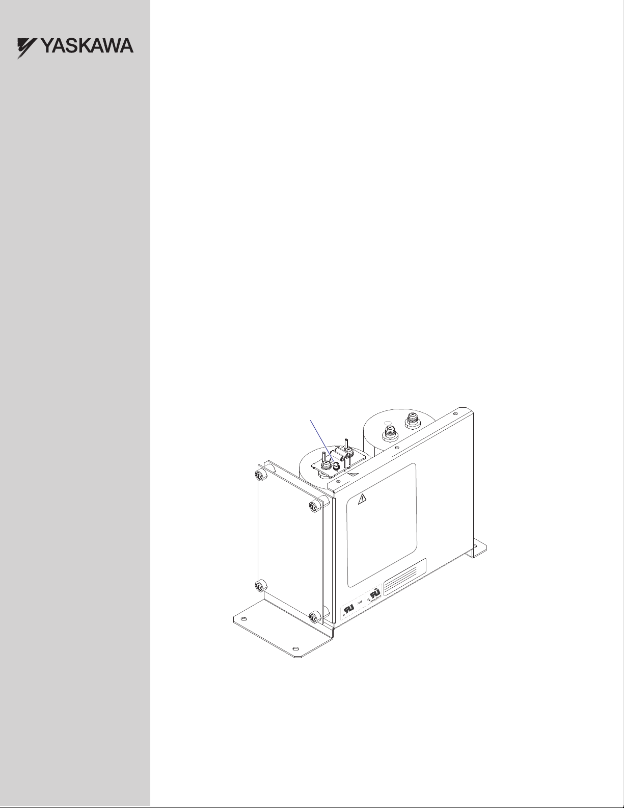
Warning Labels
Warning information is displayed on the Power Supply Unit with Charge LED as shown in the figure below. Follow all
warnings and safety instructions when using the product.
YAS KA WA TOEP YEAOPT 06 YASKAWA AC Drive - G5HHP Power Supply Unit with Charge LED Safety Precautions 5
Page 6

2 Product Overview and Receiving
WARNING
Risk of Electric Shock - Do Not T
MASS: 3.1 Kg
POWER SUPPLY UNIT
CODE NO.:
SER NO. : N4WXXXX-X-X
LOT NO.:
YASKAWA ELECTRIC CORPORATION
EUS6150XX
WARNING
Risk of Electric Shock - Do Not Touch
The internal capacitor remains charged
after the power supply is turned off.
Disconnect all power to the drive before
servicing.
Wait until the status indicator LED is off,
and then measure DC bus voltage to
confirm a safe level below 50 Vdc before
servicing. The charge indicator LED will
extinguish when the DC bus voltage is
below 50 Vdc.
Failure to comply can result in serious
injury or death from electric shock.
MASS: 3.1 Kg
POWER SUPPLY UNIT
CODE NO.:
SER NO. : N4WXXXX-X-X
LOT NO.:
YASKAWA ELECTRIC CORPORATION
EUS6150XX
2 Product Overview and Receiving
About this Product
This document contains safety precautions and procedures for ensuring safety in discharging and removing the G5 HHP
Power Supply Unit with Charge LED.
The Power Supply Unit with Charge LED has a printed circuit board (PCB) mounted charge LED which is lit when
hazardous voltages over 50 Vdc are present on the power supply. The Power Supply Unit with Charge LED also has a tap
change PCB attached to a bus capacitor bank assembly. The 1.4 kVA Power Supply Unit delivers 230 Vac fan and
contactor power along with 300 Vdc power to the inverter gate drive PCB, and the G5 control assembly.
The Power Supply Unit can accommodate various input power supply ratings ranging from 200 thru 460 Vac for the 400
volt series and 500 thru 600 Vac for the 600 volt series. Several fuses on the tap change board protect the Power Supply
Unit in the event of an overload or short circuit condition.
Applicable Models
Refer to Tab l e 1 to make sure the Power Supply Unit with Charge LED is the correct replacement part.
Table 1 Power Supply Unit with Charge LED Model Numbers
Power Supply Unit with Charge LED
G5 HHP Drive Voltage Class
Model
EUS61501
EUS61502
200/400 V Class
575/600 V Class
Receiving
Perform the following tasks after receiving this product:
• Inspect the unit for damage.
If the unit appears damaged upon receipt, contact the shipper immediately.
• Verify receipt of the correct model by checking the model number.
• If you have received the wrong model or this product does not function properly, contact your supplier.
Nameplate
Figure 1
6 YASKAWA TOEP YEAOPT 06 YASKAWA AC Drive - G5HHP Power Supply Unit with Charge LED Safety Precautions
Figure 1 Power Supply Unit with Charge LED Nameplate
Page 7

2 Product Overview and Receiving
Contents and Packaging
Table 2 Contents of Package
Description: Power Supply Unit with Charge LED Safety Precautions
Charge LED
Risk of Electric Shock - Do Not Touch
WARNING
WARNING
Risk of Electric Shock - Do Not Touch
The internal capacitor remains charged
after the power supply is turned off.
-
Disconnect all power to the drive before
servicing.
Wait until the status indicator LED is off,
and then measure DC bus voltage to
confirm a safe level below 50 Vdc before
servicing. The charge indicator LED will
extinguish when the DC bus voltage is
below 50 Vdc.
UNIT
Y
Failure to comply can result in serious
EUS6150XX
injury or death from electric shock.
POWER SUPPL
MASS: 3.1 Kg
CODE NO.:
SER NO. : N4WXXXX-X-X
LOT NO.:
YASKAWA ELECTRIC CORPORATION
Quantity: 11
MANUAL
Safety Equipment Recommendations
The following safety equipment is recommended to safely replace the Power Supply Unit with Charge LED.
Use each item as indicated in the instructions.
WARNING! Electrical Shock Hazard. Do not allow unqualified personnel to use equipment. Failure to comply could result in serious
injury or death. Maintenance, inspection, and replacement of parts must be performed only by authorized personnel familiar with
installation, adjustment, and maintenance of this product.
Table 3 Recommended Safety Equipment
Equipment Description
Calibrated multimeter (1000 Vdc) Used to measure for unsafe voltages prior to Power Supply Unit with Charge LED removal
Personal protective equipment for working with
hazardous voltages.
Fuse puller Suitable for 600 Vac circuits for 1-1/2 x 13/32 size midget fuses.
Optional Equipment - If Discharge Procedure 3 is Performed
Resistor: <1>
2000 ohm 50 watt resistor (bleed resistor)
Wire:
14 Gauge 600V rated insulated electrical wire
Electrical tape Used to insulate electrical connections when bleeding the circuit.
<1> Resistor manufacturer- Ohmite 270 series power resistor 2.0 kohms 50 W, Ohmite part number: L50J2K0 or equivalent.
Example: electrical rubber gloves, protective eye wear, insulating floor mat.
Used to bleed residual hazardous voltages from the Power Supply Unit with Charge LED prior
to removal.
Used to wire the bleed resistor circuit.
YAS KA WA TOEP YEAOPT 06 YASKAWA AC Drive - G5HHP Power Supply Unit with Charge LED Safety Precautions 7
Page 8

2 Product Overview and Receiving
WARNING
Risk of Electric Shock - Do Not Touch
The internal capacitor remains charged
after the power supply is turned off.
Disconnect all power to the drive before
servicing.
Wait until the status indicator LED is off,
and then measure DC bus voltage to
confirm a safe level below 50 Vdc before
servicing. The charge indicator LED will
extinguish when the DC bus voltage is
below 50 Vdc.
Failure to comply can result in serious
injury or death from electric shock.
MASS: 3.1 Kg
POWER SUPPLY UNIT
CODE NO.:
SER NO. : N4WXXXX-X-X
LOT NO.:
YASKAWA ELECTRIC CORPORATION
EUS6150XX
WARNING
Risk of Electric Shock - Do Not Touch
The internal capacitor remains charged after the power supply is turned off.
Disconnect all power to the drive before servicing.
Wait until the status indicator LED is off, and then measure DC bus voltage to
confirm a safe level below 50 Vdc before servicing. The charge indicator LED will
extinguish when the DC bus voltage is below 50 Vdc.
Failure to comply can result in serious injury or death from electric shock.
WARNING
Risk of Electric Shock - Do Not Touch
Risk of Electric Shock
Do Not Touch
Risk of Electric Shock
Do Not Touch
Risk of Electric Shock
Do Not Touch
WARNING
Risk of Electric Shock - Do N
The internal capacitor remains
after the power supply is turne
Disconnect all power to the dr
WARNING
Risk of Electric Shock - Do Not Touch
Charge LED
The Charge LED PCB
is present on power
supply models:
EUS61501 and EUS61502
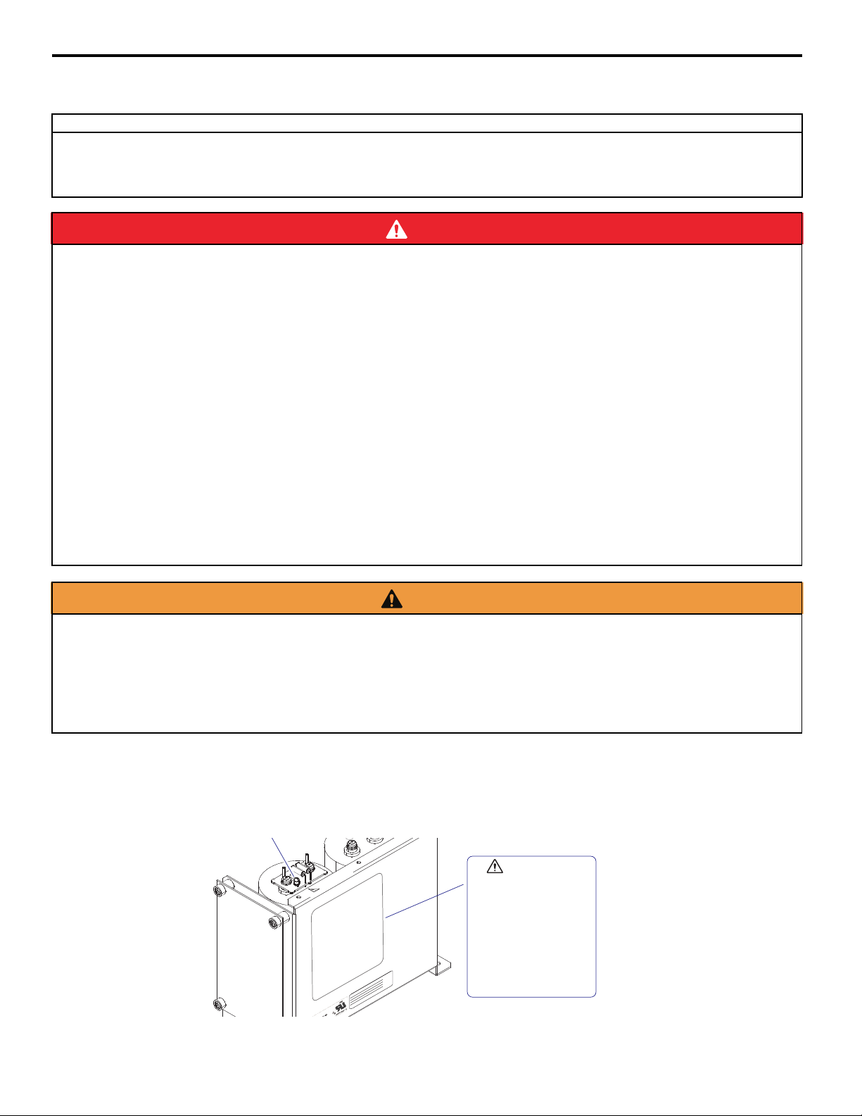
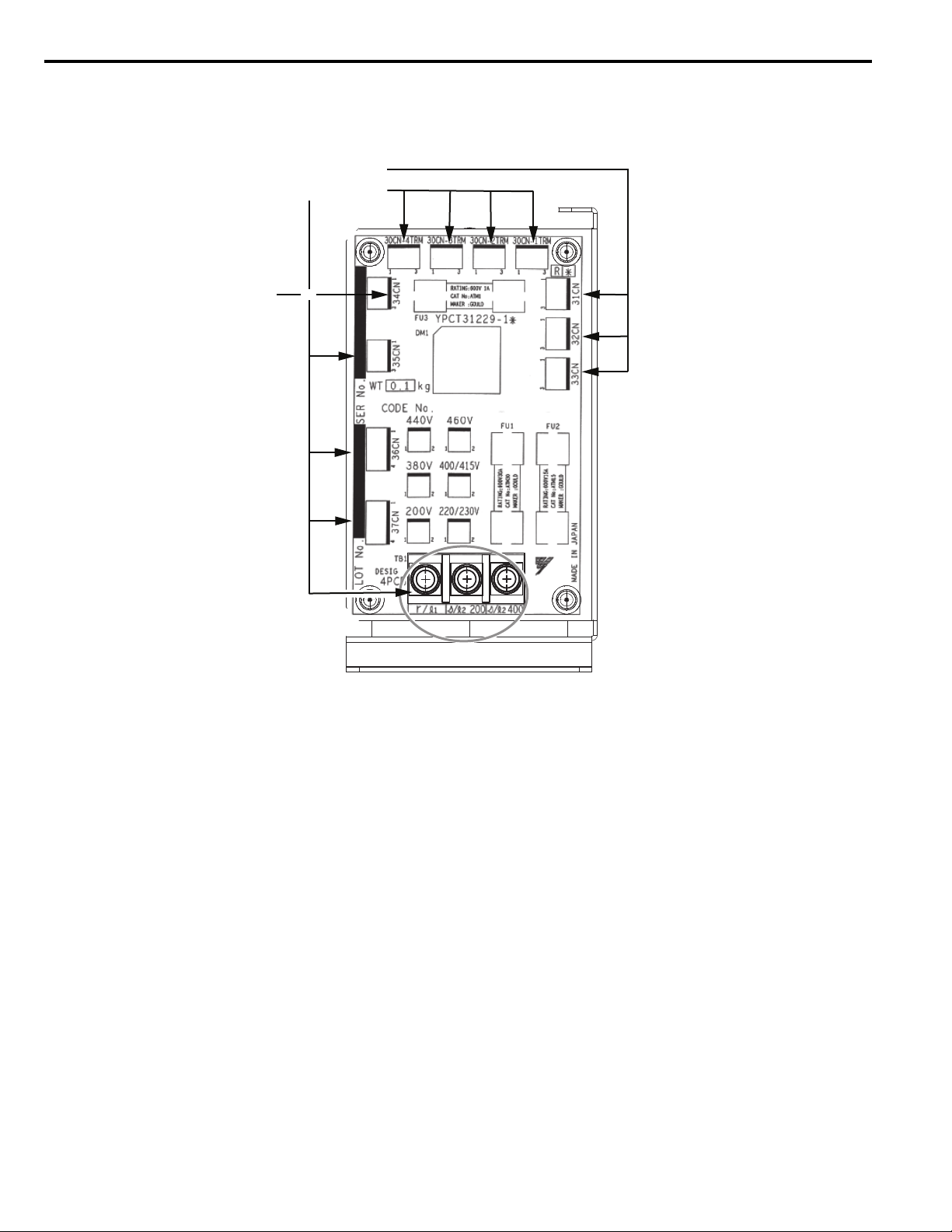
Power Supply Unit - Electric Shock Warnings
Prior to removal of the Power Supply Unit from the G5 HHP drive, become familiar with the electrical shock hazard
points shown in Figure 2.
All Power Supply Units previously installed in G5 HHP drives should be considered charged and a Shock Hazard until
safe voltages of less than 50 Vdc on bus capacitors and 0 Vac on 4PCB TB1 are verified by authorized personnel.
Figure 2
8 YA SK AWA TOEP YEAOPT 06 YASKAWA AC Drive - G5HHP Power Supply Unit with Charge LED Safety Precautions
Figure 2 Power Supply Unit - Electric Shock Warnings
Page 9

3 Safety Procedure
DANGER
W ARNING
NOTICE
3 Safety Procedure
Section Safety
Electrical Shock Hazard
Risk of Electric Shock - Do Not Touch.
The internal capacitor remains charged after the power supply is turned off. Disconnect all power to the drive before
servicing.
Wait until the status indicator LED is off and then measure DC bus voltage to confirm a safe level below 50 Vdc on bus
capacitors and 0 Vac on 4PCB TB1 before servicing. The charge indicator LED will extinguish when the DC bus
voltage is below 50 Vdc.
Failure to comply can result in serious injury or death from electric shock.
Electrical Shock Hazard
Do not allow unqualified personnel to use equipment.
Failure to comply could result in serious injury or death.
Maintenance, inspection, and replacement of parts must be performed only by authorized personnel familiar with
installation, adjustment, and maintenance of this product.
Do not use damaged wires, or damage the wire insulation.
Failure to comply could result in serious injury or death.
Fire Hazard
Tighten all terminal screws to the specified tightening torque.
Loose electrical connections could result in serious injury or death by fire due to overheating of electrical connections.
Do not operate damaged equipment.
Failure to comply may cause further damage to the equipment.
Do not connect or operate any equipment with visible damage or missing parts.
Properly connect all pins and connectors.
Failure to comply may prevent proper operation and possibly damage equipment.
Check wiring to ensure that all connections are correct after installing the Power Supply Unit with Charge LED
and connecting any other devices.
Failure to comply may result in damage to the option.
YAS KA WA TOEP YEAOPT 06 YASKAWA AC Drive - G5HHP Power Supply Unit with Charge LED Safety Precautions 9
Page 10

3 Safety Procedure
R/L1
T/L3
S/L2
U/T1
V/T2
W/T3
Motor
AC input
Drive
Three-Phase
Power Supply
200 to 600 V
50/60 Hz
R
S
T
Main
Switch
(Depending on
model capacity)
Ensuring Safety Prior to Power Supply Unit Replacement
Refer to Recommended Safety Equipment in Tab l e 3 to ensure safe handling of the Power Supply Unit prior to removal.
Summary of Safe Discharge Procedures
The Power Supply Unit may be discharged of hazardous voltages by use of three possible procedures. Under normal
conditions, assuming the drive is undamaged and fully operational, the Power Supply Unit may discharge to less than
50 Vdc within 10 minutes.
WARNING! Safe voltages must always be verified by use of a calibrated multimeter.
• DISCHARGE PROCEDURE 1: Wait 10 minutes after all power is turned off. Check for hazardous voltages with a
calibrated multimeter according to Figure 4. If voltage is less than 50 Vdc on bus capacitors and 0 Vac on 4PCB
TB1, the unit is safe from a shock hazard.
• DISCHARGE PROCEDURE 2: If hazardous voltages greater than 50 Vdc remain after 1 hour, then the Power
Supply Unit is defective and may take 8-12 hours or more to discharge. If waiting 8-12 hours is not possible then
perform Discharge Procedure 3.
• DISCHARGE PROCEDURE 3: Trained authorized personnel should use this procedure only after attempting
Discharge Procedure 1 and 2: Use a bleed resistor as shown in Figure 7 to bleed off remaining hazardous voltage to less
than 50 Vdc.
PROCEDURE: Ensuring Safety Prior to Replacing the Power Supply Unit
DANGER! Electrical Shock Hazard
Disconnect and lock out all power to the drive, before servicing.
Voltage still remains in the drive capacitors even after the Power Supply Unit and drive are deenergized. The DC bus voltage and
Power Supply Unit voltage must be below 50 Vdc on bus capacitors and and 0 Vac on 4PCB TB1 before removal. To prevent
electric shock, wait at least the amount of time specified on the drive and measure the Power Supply Unit and drive DC bus to
determine safe voltages below 50 Vdc before touching any components.
1. Disconnect all power from the drive and lock out the main power source or switch. Also disconnect and lock out
Figure 3
all remaining external power sources to the drive including seperate control or I/O power supplies.
Figure 3 Deenergize All Power
10 YA SK AWA TOEP YEAOPT 06 YASKAWA AC Drive - G5HHP Power Supply Unit with Charge LED Safety Precautions
Page 11
3 Safety Procedure
WARNING
Risk of Electric Shock - Do Not Touch
The internal capacitor remains charged
after the power supply is turned off.
Disconnect all power to the drive before
servicing.
Wait until the status indicator LED is off,
and then measure DC bus voltage to
confirm a safe level below 50 Vdc before
servicing. The charge indicator LED will
extinguish when the DC bus voltage is
below 50 Vdc.
Failure to comply can result in serious
injury or death from electric shock.
MASS: 3.1 Kg
POWER SUPPLY UNIT
CODE NO.:
SER NO. : N4WXXXX-X-X
LOT NO.:
YASKAWA ELECTRIC CORPORATION
EUS6150XX
Side View
VDC
Verify less than 50 VDC
< 50 V
+
COM
VDC
Verify less than 50 VDC
< 50 V
+
COM
VAC
Verify 0 VAC
0 V
+
COM
A
BC
WARNING
Risk of Electric Shock - Do Not Tou
The internal capacitor remains charg
after the power supply is turned off.
Disconnect all power to the drive befo
servicing.
Wait until the status indicator LED is o
WARNING
Risk of Electric Shock - Do Not Touch
Charge LED
The Charge LED PCB
is present on power
supply models:
EUS61501
and EUS61502
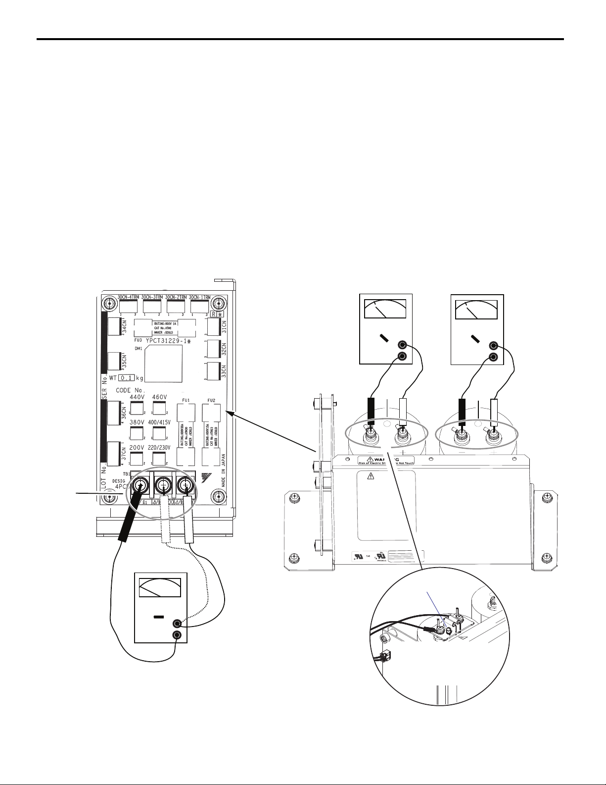
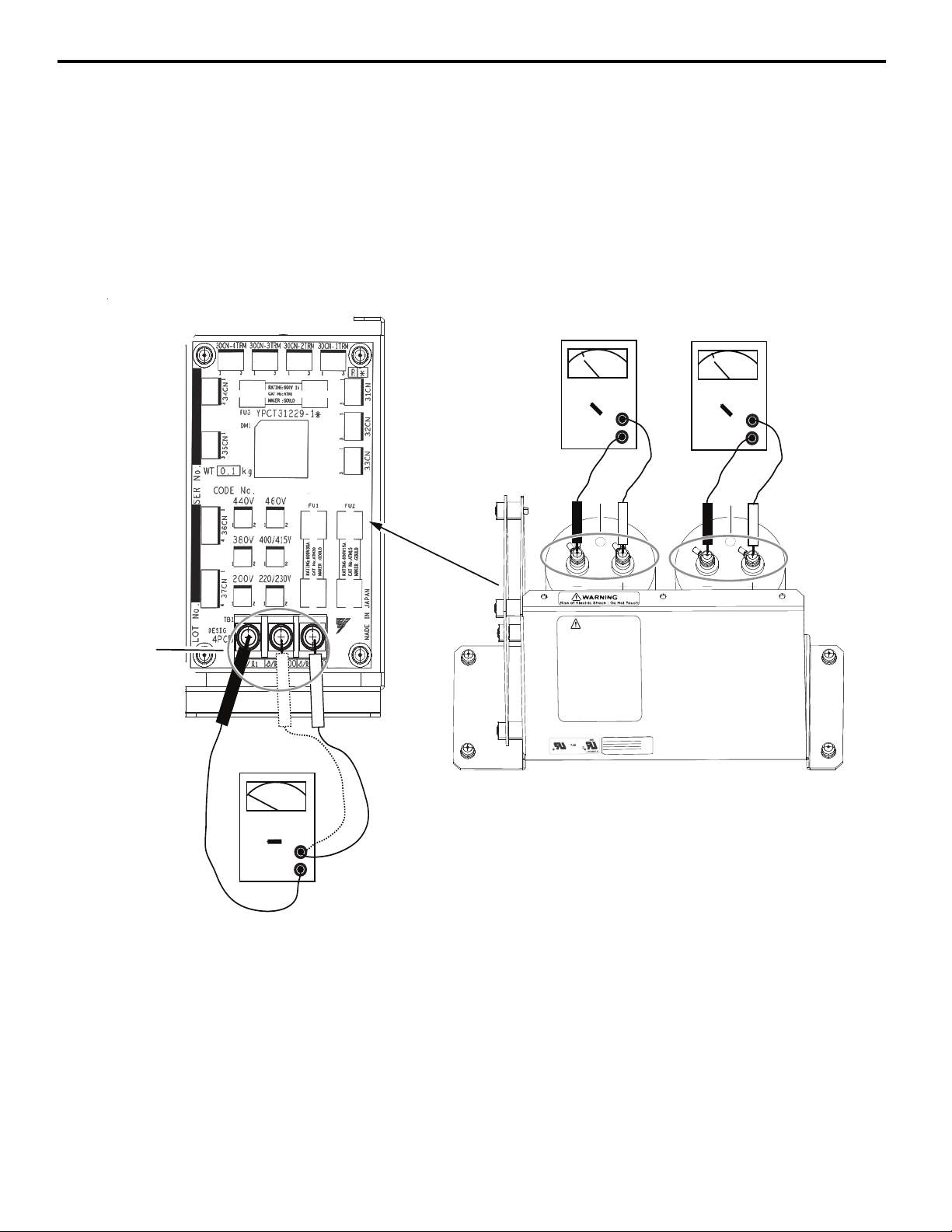
2. DISCHARGE PROCEDURE 1: Verify safe voltage levels: After waiting for at least 10 minutes, using protective
equipment recommended in Table 3 and a calibrated multimeter, check to ensure voltages are reduced to less
than 50 Vdc on bus capacitors and 0 Vac on 4PCB TB1. Refer to Figure 4 for test points on the Power Supply
Unit.
2.a. Verify the drive’s main DC bus is below a safe voltage of 50 Vdc. The main DC bus voltages can be measured
across the (+1) and (-) terminals on the converter and inverter modules.
2.b. Check Test Point (A) on TB1 between r/l1 and s200 for 0 Vac, and between r/l1 and s400 for 0 Vac.
See Figure 4. Then proceed to Step 2.c.
If Test Point (A) is not at 0 Vac then recheck that all main power and external power sources are disconnected from
the drive.
2.c. Check Test Point (B) and then (C) on Power Supply Unit capacitors between (+) and (-) screw terminals
respectively for less than 50 Vdc. See Figure 4.
If Test Points (B) or (C) are not at a safe level of 50 Vdc or less then recheck again after waiting 10 minutes. If
voltage is still not less than 50 Vdc, proceed to Step 5.
Figure 4
YAS KA WA TOEP YEAOPT 06 YASKAWA AC Drive - G5HHP Power Supply Unit with Charge LED Safety Precautions 11
Figure 4 Verifying Safe Voltages
Page 12
3 Safety Procedure
Side View
Unplug/disconnect
these plugs and wires
Do not
unplug
34CN
3. After verifying the Power Supply Unit is safe, unplug and disconnect all wire connections and plugs from 4PCB
Tap Change Card as shown in Figure 5. Use an insulated #2 phillips screwdriver to remove wire connections on
Figure 5
terminal TB1.
Figure 5 Power Supply Unit Plug and Removal on 4PCB
4. Remove the Power Supply Unit from the drive and install the replacement unit.
Ensure all plugs and wires are properly connected prior to applying power to the drive.
During removal, take precautions to ensure that nothing touches or comes into contact with the power supply bus
capacitor terminals that may still contain low voltages.
12 YA SK AWA TOEP YEAOPT 06 YASKAWA AC Drive - G5HHP Power Supply Unit with Charge LED Safety Precautions
Page 13
3 Safety Procedure
5. DISCHARGE PROCEDURE 2: If hazardous voltages remain greater than 50 Vdc on the power supply bus
capacitors after 1 hour, then the Power Supply Unit is defective and may take 8-12 hours or more to discharge.
5.a. Wait overnight or a minimum of 8-12 hours with all power removed from the drive.
5.b. Recheck for hazardous voltages as shown in Figure 6 test points (A), (B), and (C).
5.c. If voltage is reduced to a safe level of less than 50 Vdc on bus capacitors and 0 Vac on 4PCB TB1 then remove
the Power Supply Unit according to STEPS 3. and 4.
WARNING! Safe voltages must always be verified by use of a calibrated multimeter.
Figure 6
A
Side View
Verify 0 VAC
Verify less than 50 VDC
< 50 V
VDC
+
COM
Verify less than 50 VDC
< 50 V
VDC
+
COM
BC
WARNING
Risk of Electric Shock - Do Not Touch
The internal capacitor remains charged
after the power supply is turned off.
Disconnect all power to the drive before
servicing.
Wait until the status indicator LED is off,
and then measure DC bus voltage to
confirm a safe level below 50 Vdc before
servicing. The charge indicator LED will
extinguish when the DC bus voltage is
below 50 Vdc.
Failure to comply can result in serious
injury or death from electric shock.
POWER SUPPLY UNIT
EUS6150XX
CODE NO.:
SER NO. : N4WXXXX-X-X
MASS: 3.1 Kg
LOT NO.:
YASKAWA ELECTRIC CORPORATION
0 V
VAC
+
COM
Wait 8- 12 hours
minimum, then recheck
for unsafe voltages.
Figure 6 Wait 8-12 Hours Then Recheck for Unsafe Voltage
YAS KA WA TOEP YEAOPT 06 YASKAWA AC Drive - G5HHP Power Supply Unit with Charge LED Safety Precautions 13
Page 14

3 Safety Procedure
WARNING
Risk of Electric Shock - Do Not Touch
The internal capacitor remains charged after the power supply is turned off.
Disconnect all power to the drive before servicing.
Measure Wait until the status indicator LED is off, and then measure the DC
bus voltage to confirm a safe level below 50 Vdc before servicing. The charge
indicator LED will extinguish when the DC bus voltage is below 50 Vdc.
Failure to comply can result in death or serious injury from electric shock.
WARNING
Risk of Electric Shock - Do Not Touch
2000 Ohm
50 Watt Resistor
A
B
C
Side View
Use fuse puller and remove fuse FU3 before
connecting the 2000 ohm bleed resistor.
FU3
WARNING
Risk of Electric Shock - Do Not Touch
The internal capacitor remains charged
after the power supply is turned off.
Disconnect all power to the drive before
servicing.
Wait until the status indicator LED is off,
and then measure DC bus voltage to
confirm a safe level below 50 Vdc before
servicing. The charge indicator LED will
extinguish when the DC bus voltage is
below 50 Vdc.
Failure to comply can result in serious
injury or death from electric shock.
MASS: 3.1 Kg
POWER SUPPLY UNIT
CODE NO.:
SER NO. : N4WXXXX-X-X
LOT NO.:
YASKAWA ELECTRIC CORPORATION
EUS6150XX
6. DISCHARGE PROCEDURE 3: Use this procedure only if necessary: If unsafe voltages greater than 50 Vdc are
present after 1 hour and waiting 8-12 hours is not possible.
WARNING! Safe voltages must always be verified by use of a calibrated multimeter.
NOTICE: Spark Hazard. A small arc or spark may occur when touching the bleed resistor to the (+) and (-) terminals as shown in
Figure 7. This is normal and does not present a hazard in non-combustable environments.
Following steps 6.a to 6.d below use the discharge circuit shown in Figure 7 to bleed off remaining hazardous
voltage to less than 50 Vdc. Utilize personal protective equipment as specified in Tab le 3.
6.a. Remove fuse FU3 by use of a fuse puller to electrically isolate the drive from the power supply. See Figure 7.
6.b. Connect the bleed resistor across the plus (+) and minus (-) bus capacitor terminals on the Power Supply Unit for
1 minute. Remove the bleed resistor. See Figure 7.
6.c. Using a calibrated multimeter, recheck for hazardous voltages. Refer to Figure 4. If voltages are at a safe level
less than 50 Vdc on bus capacitors and and 0 Vac on 4PCB TB1 then the Power Supply Unit can be safely removed
according to STEP 3.
6.d. If voltages on bus capacitors are still greater than 50 Vdc, repeat procedure steps 6.b and 6.c until voltages are
less than 50 Vdc, then remove the Power Supply Unit.
Figure 7
A – Insulated test probes rated 600 Vac
minimum
B – Insulated resistor: 2000 ohm 50 W. Resistor manufacturer- Ohmite 270 series power
resistor 2.0 kohms 50 W, part number: L50J2K0 or equivalent.
NOTE: Resistor must be insulated. Use electrical tape or heat shrink tubing.
Figure 7 Discharge Procedure 3, Use of a Bleed Resistor
7. END.
C – 14 ga insulated wire rated 600 Vac
minimum
14 YA SK AWA TOEP YEAOPT 06 YASKAWA AC Drive - G5HHP Power Supply Unit with Charge LED Safety Precautions
Page 15

3 Safety Procedure
This Page Intentionally Blank
YAS KA WA TOEP YEAOPT 06 YASKAWA AC Drive - G5HHP Power Supply Unit with Charge LED Safety Precautions 15
Page 16

YASKAWA AC Drive - G5 HHP
Power Supply Unit
with Charge LED
Safety Precautions
In the event that the end user of this product is to be the military and said product is to be employed in any weapons systems or the manufacture
thereof, the export will fall under the relevant regulations as stipulated in the Foreign Exchange and Foreign Trade Regulations. Therefore, be sure
to follow all procedures and submit all relevant documentation according to any and all rules, regulations and laws that may apply.
Specifications are subject to change without notice for ongoing product modifications and improvements.
© 2010 YASKAWA AMERICA, INC. All rights reserved.
MANUAL NO. TOEP YEAOPT 06
Published in U.S.A. October 2010 10-7
 Loading...