

Page 1

MOTOMAN-ES165D
1 of 92
INSTRUCTIONS
TYPE:
YR-ES0165D-A00 (STANDARD SPECIFICATION)
YR-ES0165D-A01 (SLU-AXES WITH LIMIT SWITCHES)
Upon receipt of the product and prior to initial operation, read these instructions thoroughly, and retain
for future reference.
MOTOMAN INSTRUCTIONS
MOTOVAN-ES165D INSTRUCTIONS
DX100 INSTRUCTIONS
DX100 OPERATOR’S MANUAL
DX100 MAINTENANCE MANUAL
The DX100 operator’s manual above corresponds to specific usage.
Be sure to use the appropriate manual.
Part Number: 155976-1CD
Revision: 6
MANUAL NO.
HW0485249
9
Page 2

ES165D
2 of 92
155976-1CD
Copyright © 2017, 2013 Yaskawa America, Inc.
Terms of Use and Copyright Notice
All rights reserved. This manual is freely available as a service to Yaskawa
customers to assist in the operation of Motoman robots, related equipment
and software This manual is copyrighted property of Yaskawa and may
not be sold or redistributed in any way. You are welcome to copy this
document to your computer or mobile device for easy access but you may
not copy the PDF files to another website, blog, cloud storage site or any
other means of storing or distributing online content.
Printed in the United States of America
First Printing, 2016
Yaskawa America, Inc.
Motoman Robotics Division
100 Automation Way
Miamisburg, OH 45342
Phone: 937-847-6200
www.motoman.com
ii
HW0485249
Page 3
155976-1CD
MANDATORY
CAUTION
3 of 92
ES165D
• This instruction manual is intended to explain mainly on the
mechanical part of the MOTOMAN-ES165D for the application to
the actual operation and for proper maintenance and inspection. It
describes on safety and handling, details on specifications,
necessary items on maintenance and inspection, to explain
operating instructions and maintenance procedures. Be sure to
read and understand this instruction manual thoroughly before
installing and operating the manipulator.
• General items related to safety are listed in Chapter 1: Safety of the
DX100 Instructions. To ensure correct and safe operation, carefully
read the DX100 Instructions before reading this manual.
• Some drawings in this manual are shown with the protective covers
or shields removed for clarity. Be sure all covers and shields are
replaced before operating this product.
• The drawings and photos in this manual are representative
examples and differences may exist between them and the
delivered product.
• YASKAWA may modify this model without notice when necessary
due to product improvements, modifications, or changes in
specifications.
If such modification is made, the manual number will also be
revised.
• If your copy of the manual is damaged or lost, contact a YASKAWA
representative to order a new copy. The representatives are listed
on the back cover. Be sure to tell the representative the manual
number listed on the front cover.
• YASKAWA is not responsible for incidents arising from unauthorized
modification of its products. Unauthorized modification voids your
product's warranty.
iii
HW0485249
Page 4

ES165D
4 of 92
155976-1CD
We suggest that you obtain and review a copy of the ANSI/RIA National
Safety Standard for Industrial Robots and Robot Systems (ANSI/RIA
R15.06-2012). You can obtain this document from the Robotic Industries
Association (RIA) at the following address:
Robotic Industries Association
900 Victors Way
P.O. Box 3724
Ann Arbor, Michigan 48106
TEL: (734) 994-6088
FAX: (734) 994-3338
www.roboticsonline.com
Ultimately, well-trained personnel are the best safeguard against
accidents and damage that can result from improper operation of the
equipment. The customer is responsible for providing adequately trained
personnel to operate, program, and maintain the equipment. NEVER
ALLOW UNTRAINED PERSONNEL TO OPERATE, PROGRAM, OR
REPAIR THE EQUIPMENT!
We recommend approved Yaskawa training courses for all personnel
involved with the operation, programming, or repair of the equipment.
This equipment has been tested and found to comply with the limits for a
Class A digital device, pursuant to part 15 of the FCC rules. These limits
are designed to provide reasonable protection against harmful
interference when the equipment is operated in a commercial
environment. This equipment generates, uses, and can radiate radio
frequency energy and, if not installed and used in accordance with the
instruction manual, may cause harmful interference to radio
communications.
iv
HW0485249
Page 5
155976-1CD
CAUTION
MANDATORY
PROHIBITED
NOTE
5 of 92
ES165D
Notes for Safe Operation
Notes for Safe Operation
Read this manual carefully before installation, operation, maintenance, or
inspection of the MOTOMAN-ES165D.
In this manual, the Notes for Safe Operation are classified as “DANGER”,
“WARNING”, “CAUTION”, “MANDATORY”, or “PROHIBITED”.
DANGER
WARNING
Indicates an imminent hazardous
situation which, if not avoided, could
result in death or serious injury to
personnel.
Indicates a potentially hazardous
situation which, if not avoided, could
result in death or serious injury to
personnel.
Indicates a potentially hazardous
situation which, if not avoided, could
result in minor or moderate injury to
personnel and damage to equipment.
It may also be used to alert against
unsafe practices.
Always be sure to follow explicitly the
items listed under this heading.
Must never be performed.
Even items described as “CAUTION” may result in a serious accident in
some situations.
At any rate, be sure to follow these important items.
To ensure safe and efficient operation at all times, be sure to
follow all instructions, even if not designated as “DANGER”,
“WARNING” and “CAUTION”.
DANGER
• Maintenance and inspection must be performed by specified
personnel.
Failure to observe this caution may result in electric shock or injury.
• For disassembly or repair, contact your YASKAWA representative.
• Do not remove the motor, and do not release the brake.
Failure to observe these safety precautions may result in death or
serious injury from unexpected turning of the manipulator's arm.
v
HW0485249
Page 6
ES165D
TURN
6 of 92
155976-1CD
Notes for Safe Operation
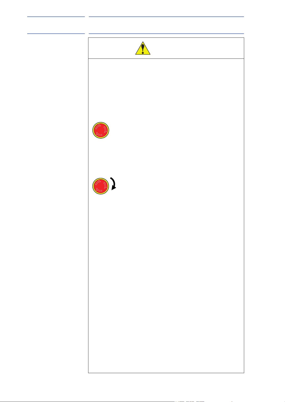
WARNING
• Before operating the manipulator, check that servo power is turned
OFF pressing the emergency stop buttons on the front door of the
DX100 and the programming pendant.
When the servo power is turned OFF, the SERVO ON LED on the
programming pendant is turned OFF.
Injury or damage to machinery may result if the emergency stop circuit
cannot stop the manipulator during an emergency. The manipulator
should not be used if the emergency stop buttons do not function.
Figure 1: Emergency Stop Button
• Once the emergency stop button is released, clear the cell of all
items which could interfere with the operation of the manipulator.
Then turn the servo power ON.
Injury may result from unintentional or unexpected manipulator motion.
Figure 2: Release of Emergency Stop
• Observe the following precautions when performing teaching
operations within the P-point maximum envelope of the
manipulator:
– Be sure to use a lockout device to the safeguarding when going
inside. Also, display the sign that the operation is being
performed inside the safeguarding and make sure no one closes
the safeguarding.
– View the manipulator from the front whenever possible.
– Always follow the predetermined operating procedure.
– Keep in mind the emergency response measures against the
manipulator’s unexpected motion toward you.
– Ensure that you have a safe place to retreat in case of
emergency.
Improper or unintended manipulator operation may result in injury.
• Confirm that no person is present in the P-point maximum envelope
of the manipulator and that you are in a safe location before:
– Turning ON the power for the DX100.
– Moving the manipulator with the programming pendant.
– Running the system in the check mode.
– Performing automatic operations.
Injury may result if anyone enters the P-point maximum envelope of the
manipulator during operation. Always press an emergency stop button
immediately if there is a problem.
The emergency stop buttons are located on the right of front door of the
DX100 and the programming pendant.
vi
HW0485249
Page 7
155976-1CD
CAUTION
7 of 92
ES165D
Definition of Terms Used In this Manual
• Perform the following inspection procedures prior to conducting
manipulator teaching. If problems are found, repair them
immediately, and be sure that all other necessary processing has
been performed.
– Check for problems in manipulator movement.
– Check for damage to insulation and sheathing of external wires.
• Always return the programming pendant to the hook on the cabinet
of the DX100 after use.
The programming pendant can be damaged if it is left in the
manipulator's work area, on the floor, or near fixtures.
• Read and understand the Explanation of Warning Labels in the
DX100 Instructions before operating the manipulator:
Definition of Terms Used In this Manual
The MOTOMAN is the YASKAWA industrial robot product.
The MOTOMAN usually consists of the manipulator, the controller, the
programming pendant, and the manipulator cables.
In this manual, the equipment is designated as follows:
Equipment Manual Designation
DX100 controller DX100
DX100 programming pendant Programming pendant
Cable between the manipulator and the
controller
Description of the Operation Procedure
In the explanation of the operation procedure, the expression “Select • • •”
means that the cursor is moved to the object item and the SELECT key is
pressed, or that the item is directly selected by touching the screen.
Registered Trademark
In this manual, names of companies, corporations, or products are
trademarks, registered trademarks, or brand names for each company or
corporation. The indications of (R) and TM are omitted.
Manipulator cable
vii
HW0485249
Page 8
ES165D
8 of 92
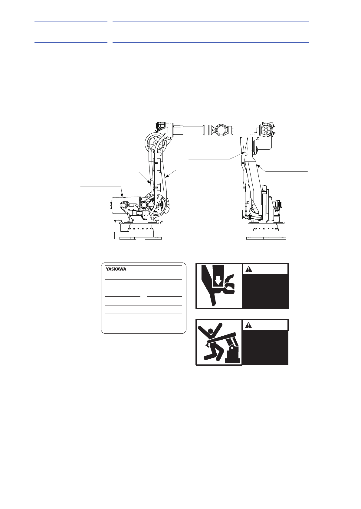
Explanation of Warning Labels
Explanation of Warning Labels
The following warning labels are attached to the manipulator.
Always follow the warnings on the labels.
Also, an identification label with important information is placed on the
body of the manipulator. Prior to operating the manipulator, confirm the
contents.
Figure 3: Warning Label Locations
155976-1CD
WARNING Label B
Nameplate
WARNING Label A
Nameplate:
MODEL
MOTOMANTYPE
PAYLOAD
ORDERNO.
SERIALNO.
YASKAWAELECTRICCORPORATION
2-1Kurosakishiroishi,Yahatanishi-ku,
Kitakyushu806-0004Japan
MADEINJAPAN
WARNING Label A
WARNING Label A:
WARNING Label B
WARNING
Moving parts
MASS
kg
DATE
kg
WARNING Label B:
NJ3878
may cause
injury
WARNING
Do not enter
robot
work area.
viii
HW0485249
Page 9

155976-1CD
9 of 92
ES165D
Safeguarding Tips
Safeguarding Tips
All operators, programmers, maintenance personnel, supervisors, and
anyone working near the system must become familiar with the operation
of this equipment. All personnel involved with the operation of the
equipment must understand potential dangers of operation. General
safeguarding tips are as follows:
• Improper operation can result in personal injury and/or damage to
the equipment. Only trained personnel familiar with the operation of
this equipment, the operator's manuals, the system equipment, and
options and accessories should be permitted to operate this
equipment.
• Improper connections can damage the equipment. All connections
must be made within the standard voltage and current ratings of the
equipment.
• The system must be placed in Emergency Stop (E-Stop) mode
whenever it is not in use.
• In accordance with ANSI/RIA R15.06-2012, section 4.2.5, Sources of
Energy, use lockout/tagout procedures during equipment
maintenance. Refer also to Section 1910.147 (29CFR, Part 1910),
Occupational Safety and Health Standards for General Industry
(OSHA).
Mechanical Safety Devices
The safe operation of this equipment is ultimately the users responsibility.
The conditions under which the equipment will be operated safely should
be reviewed by the user. The user must be aware of the various national
codes, ANSI/RIA R15.06-2012 safety standards, and other local codes
that may pertain to the installation and use of this equipment.
Additional safety measures for personnel and equipment may be required
depending on system installation, operation, and/or location. The following
safety equipment is provided as standard:
• Safety barriers
• Door interlocks
• Emergency stop palm buttons located on operator station
Check all safety equipment frequently for proper operation. Repair or
replace any non-functioning safety equipment immediately.
ix
HW0485249
Page 10

ES165D
10 of 92
Programming, Operation, and Maintenance Safety
Programming, Operation, and Maintenance Safety
All operators, programmers, maintenance personnel, supervisors, and
anyone working near the system must become familiar with the operation
of this equipment. Improper operation can result in personal injury and/or
damage to the equipment. Only trained personnel familiar with the
operation, manuals, electrical design, and equipment interconnections of
this equipment should be permitted to program, or maintain the system.
All personnel involved with the operation of the equipment must
understand potential dangers of operation.
• Inspect the equipment to be sure no potentially hazardous conditions
exist. Be sure the area is clean and free of water, oil, debris, etc.
• Be sure that all safeguards are in place. Check all safety equipment
for proper operation. Repair or replace any non-functioning safety
equipment immediately.
• Check the E-Stop button on the operator station for proper operation
before programming. The equipment must be placed in Emergency
Stop (E-Stop) mode whenever it is not in use.
155976-1CD
• Back up all programs and jobs onto suitable media before program
changes are made. To avoid loss of information, programs, or jobs, a
backup must always be made before any service procedures are
done and before any changes are made to options, accessories, or
equipment.
• Any modifications to the controller unit can cause severe personal
injury or death, as well as damage to the robot! Do not make any
modifications to the controller unit. Making any changes without the
written permission from Yaskawa will void the warranty.
• Some operations require standard passwords and some require
special passwords.
• The equipment allows modifications of the software for maximum
performance. Care must be taken when making these modifications.
All modifications made to the software will change the way the
equipment operates and can cause severe personal injury or death,
as well as damage parts of the system. Double check all
modifications under every mode of operation to ensure that the
changes have not created hazards or dangerous situations.
• This equipment has multiple sources of electrical supply. Electrical
interconnections are made between the controller and other
equipment. Disconnect and lockout/tagout all electrical circuits
before making any modifications or connections.
• Do not perform any maintenance procedures before reading and
understanding the proper procedures in the appropriate manual.
• Use proper replacement parts.
• Improper connections can damage the equipment. All connections
must be made within the standard voltage and current ratings of the
equipment.
x
HW0485249
Page 11

155976-1CD
11 of 92
ES165D
Maintenance Safety
Maintenance Safety
Turn the power OFF and disconnect and lockout/tagout all electrical
circuits before making any modifications or connections.
Perform only the maintenance described in this manual. Maintenance
other than specified in this manual should be performed only by Yaskawatrained, qualified personnel.
Summary of Warning Information
This manual is provided to help users establish safe conditions for
operating the equipment. Specific considerations and precautions are also
described in the manual, but appear in the form of Dangers, Warnings,
Cautions, and Notes.
It is important that users operate the equipment in accordance with this
instruction manual and any additional information which may be provided
by Yaskawa. Address any questions regarding the safe and proper
operation of the equipment to Yaskawa Motoman Customer Support.
xi
HW0485249
Page 12

ES165D
NOTE
(937) 847-3200
12 of 92
Customer Support Information
Customer Support Information
If you need assistance with any aspect of your ES165D system, please
contact YASKAWA Customer Support at the following 24-hour telephone
number:
For routine technical inquiries, you can also contact YASKAWA Customer
Support at the following e-mail address:
When using e-mail to contact YASKAWA Customer Support, please
provide a detailed description of your issue, along with complete contact
information. Please allow approximately 24 to 36 hours for a response to
your inquiry.
155976-1CD
techsupport@motoman.com
Please use e-mail for routine inquiries only. If you have an
urgent or emergency need for service, replacement parts,
or information, you must contact YASKAWA Customer
Support at the telephone number shown above.
Please have the following information ready before you call Customer
Support:
• System ES165D
• Robots ___________________________
• Primary Application ___________________________
• Controller DX100
• Software Version Access this information on the
Programming Pendant’s LCD
display screen by selecting {MAIN
MENU} - {SYSTEM INFO} {VERSION}
• Robot Serial Number Located on the robot data plate
• Robot Sales Order Number Located on the DX100 controller
data plate
xii
HW0485249
Page 13

155976-1CD
13 of 92
ES165D
Table of Contents
Table of Contents
1 Product Confirmation ...................................................................................................................... 1-1
1.1 Contents Confirmation ....................................................................................................... 1-1
1.2 Order Number Confirmation .............................................................................................. 1-2
2 Transport......................................................................................................................................... 2-1
2.1 Transport Method .............................................................................................................. 2-1
2.1.1 Using a Crane ...................................................................................................... 2-2
2.2 Shipping Bolts and Brackets.............................................................................................. 2-3
3 Installation....................................................................................................................................... 3-1
3.1 Safeguarding Installation ................................................................................................... 3-2
3.2 Mounting Procedures for Manipulator Base ...................................................................... 3-2
3.2.1 Mounting Example................................................................................................ 3-3
3.3 Location ............................................................................................................................. 3-3
4 Wiring.............................................................................................................................................. 4-1
4.1 Grounding .......................................................................................................................... 4-1
4.2 Cable Connection .............................................................................................................. 4-2
4.2.1 Connection to the Manipulator.............................................................................. 4-2
4.2.2 Connection to the DX100 ..................................................................................... 4-2
5 Basic Specifications ........................................................................................................................ 5-1
5.1 Basic Specifications........................................................................................................... 5-1
5.2 Part Names and Working Axes.......................................................................................... 5-2
5.3 Manipulator Base Dimensions ........................................................................................... 5-2
5.4 Dimensions and P-Point Maximum Envelope.................................................................... 5-3
5.5 Alterable Operating Range ................................................................................................ 5-4
5.5.1 Components for Altering Operating Range .......................................................... 5-5
5.5.2 Notes on the Mechanical Stopper Installation ...................................................... 5-6
5.5.3 Adjustment to the Pulse Limitation of S-Axis........................................................ 5-7
6 Allowable Load for Wrist Axis and Wrist Flange ............................................................................. 6-1
6.1 Allowable Wrist Load ......................................................................................................... 6-1
6.2 Wrist Flange....................................................................................................................... 6-3
xiii
HW0485249
Page 14

155976-1CD
14 of 92
ES165D
7 System Application.......................................................................................................................... 7-1
7.1 Peripheral Equipment Mounts............................................................................................ 7-1
7.2 Internal User I/O Wiring Harness and Air Line................................................................... 7-2
8 Electrical Equipment Specification .................................................................................................. 8-1
8.1 Position of Limit Switch ...................................................................................................... 8-1
8.1.1 Specification of Limit Switch ................................................................................. 8-1
8.1.2 Location of Limit Switch ........................................................................................ 8-1
8.1.3 Setting of Operation Range .................................................................................. 8-2
8.1.3.1 S-Axis Operation Range.......................................................................... 8-2
8.1.3.2 L-Axis Operation Range .......................................................................... 8-2
8.1.3.3 Setting Range of LU-Axes Interference Angle......................................... 8-3
8.2 Internal Connections .......................................................................................................... 8-4
Table of Contents
9 Maintenance and Inspection ........................................................................................................... 9-1
9.1 Inspection Schedule........................................................................................................... 9-1
9.2 Notes on Maintenance Procedures.................................................................................... 9-6
9.2.1 Battery Pack Replacement ................................................................................... 9-6
9.3 Notes on Grease Replenishment/Exchange Procedures .................................................. 9-8
9.3.1 Grease Replenishment/Exchange for S-Axis Speed Reducer ............................. 9-8
9.3.1.1 Grease Replenishment............................................................................ 9-9
9.3.1.2 Grease Exchange.................................................................................... 9-9
9.3.2 Grease Replenishment/Exchange for L-Axis Speed Reducer............................ 9-10
9.3.2.1 Grease Exchange.................................................................................. 9-10
9.3.2.2 Grease Exchange.................................................................................. 9-11
9.3.3 Grease Replenishment/Exchange for U-Axis Speed Reducer ........................... 9-12
9.3.3.1 Grease Replenishment.......................................................................... 9-12
9.3.3.2 Grease Exchange.................................................................................. 9-13
9.3.4 Grease Replenishment/Exchange for U-Arm ..................................................... 9-14
9.3.4.1 Grease Replenishment for R-, B-, T-Axes Gears in the Casing ............9-14
9.3.4.2 Grease Replenishment for R-Axis Speed Reducer ............................... 9-15
9.3.4.3 Grease Replenishment for B-Axis Speed Reducer ............................... 9-16
9.3.4.4 Grease Replenishment for T-Axis Speed Reducer ............................... 9-16
9.3.4.5 Grease Exchange for R-, B-, T-Axes Gears in the Casing .................... 9-17
9.3.4.6 Grease Exchange for R-Axis Speed Reducer ....................................... 9-17
9.3.4.7 Grease Exchange for B-Axis Speed Reducer ....................................... 9-18
9.3.4.8 Grease Exchange for T-Axis Speed Reducer ....................................... 9-19
9.3.5 Grease Replenishment for Balancer Connection Part........................................ 9-20
9.3.6 Notes for Maintenance........................................................................................ 9-21
9.3.6.1 Battery Pack Connection ....................................................................... 9-21
xiv
HW0485249
Page 15

155976-1CD
15 of 92
ES165D
10 Recommended Spare Parts........................................................................................................ 10-1
11 Parts List ..................................................................................................................................... 11-1
11.1 S-Axis Unit ..................................................................................................................... 11-1
11.2 L-Axis Unit ..................................................................................................................... 11-3
11.3 URBT-Axes Unit ............................................................................................................ 11-5
11.4 U-Arm Unit ..................................................................................................................... 11-8
11.5 Wrist Unit ..................................................................................................................... 11-10
11.6 Balancer Unit ............................................................................................................... 11-13
Table of Contents
xv
HW0485249
Page 16

ES165D
CAUTION
16 of 92
1 Product Confirmation
1.1 Contents Confirmation
1 Product Confirmation
• Confirm that the manipulator and the DX100 have the same order
number. Special care must be taken when more than one
manipulator is to be installed.
If the numbers do not match, manipulators may not perform as
expected and cause injury or damage.
1.1 Contents Confirmation
Confirm the contents of the delivery when the product arrives.
Standard delivery includes the following four items (information for the
content of optional goods are given separately):
155976-1CD
• Manipulator
• DX100
• Programming pendant
• Manipulator cables (3 cables between the DX100 and the
Manipulator)
1-1
HW0485249
Page 17
155976-1CD
X81
PROGRAMMING PENDANT
Y
C
E
G
N
O
T
P
M
E
E
S
R
ON
TRIPPED
RESET
OFF
AVERAGE
PEAK
kVA
kA
INTERRUPT CURRENT
ERDR-
POWER SUPPLY
TYPE
DX100
kVA
3PHASE
NJ2960-1
60Hz
SERIAL No.
DATE
AC220V
MADE IN JAPAN
50/60HzAC200V
NJ1529
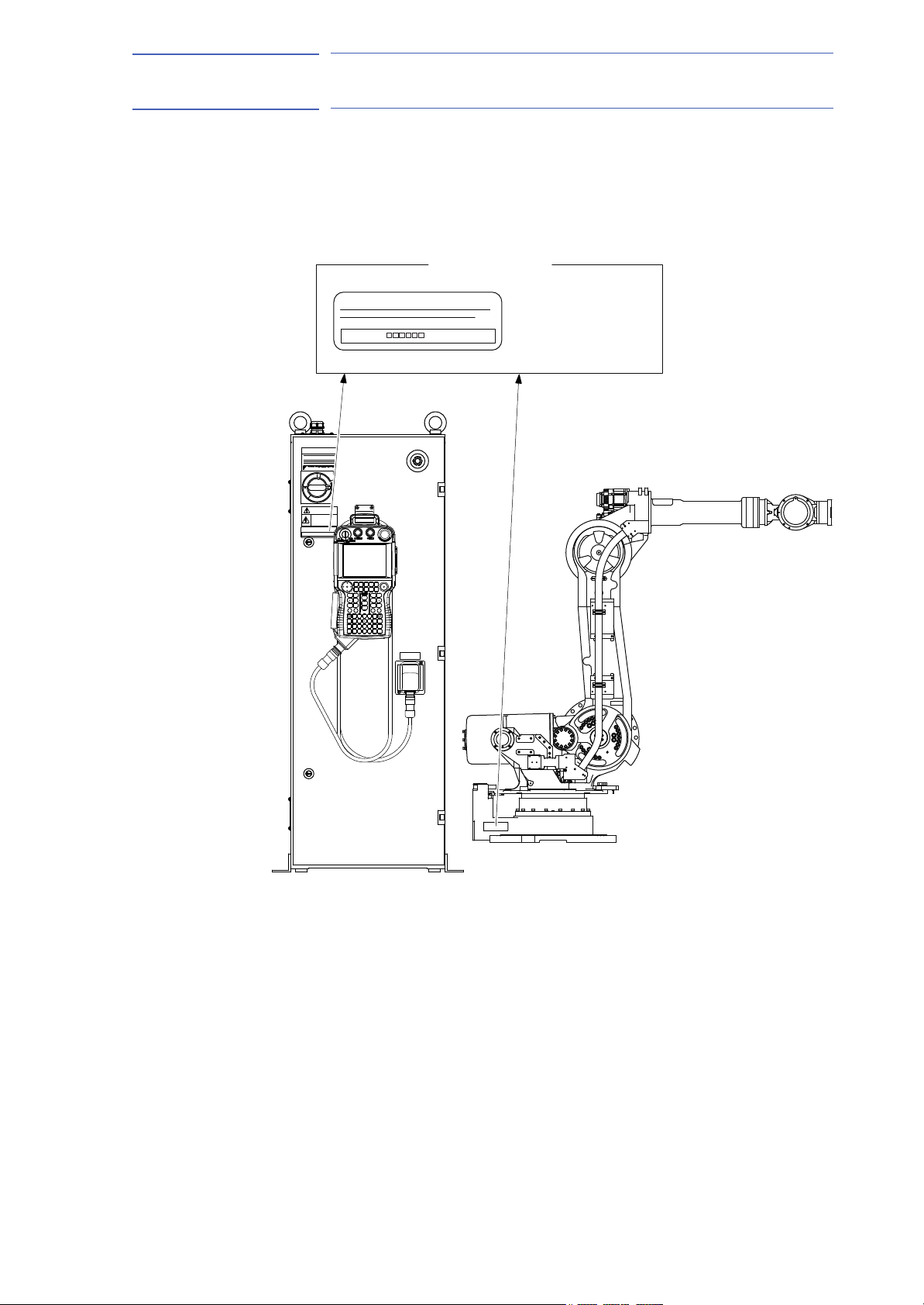
THE MANIPULATOR AND THE CONTROLLER
SHOULD HAVE SAME ORDER NUMBER.
ORDER NO.
Check that the manipulator
and the DX100 have the
same order number.
Label (Enlarged View)
(b) Manipulator (Side View)(a) DX100 (Front View)
WARNING
Do not open the door
THE MANIPULATOR AND THE CONTROLLER
SHOULD HAVE SAME ORDER NUMBER.
ORDER NO.
17 of 92
ES165D
1 Product Confirmation
1.2 Order Number Confirmation
1.2 Order Number Confirmation
Check that the order number of the manipulator corresponds to the
DX100. The order number is located on a label as shown below.
Fig. 1-1: Location of Order Number Labels
1-2
HW0485249
Page 18
ES165D
CAUTION
NOTE
18 of 92
2 Transport
155976-1CD
2 Transport
2.1 Transport Method
• Sling applications and crane or forklift operations must be
performed by authorized personnel only.
Failure to observe this caution may result in injury or damage.
• Avoid excessive vibration or shock during transport.
The system consists of precision components. Failure to observe this
caution may adversely affect performance.
2.1 Transport Method
• The weight of the manipulator is approximately 1150 kg
including the shipping bolts and brackets. Use a wire rope
strong enough to withstand the weight.
• Shipping bolts and brackets are designed to support the
manipulator weight. Do not use them for anything other
than transporting the manipulator.
• Mount the shipping bolts and brackets for transporting the
manipulator.
• Avoid putting external force on the arm or motor unit when
transporting by a crane, forklift, or other equipment.
Failure to observe this instruction may result in injury.
2-1
HW0485249
Page 19
155976-1CD
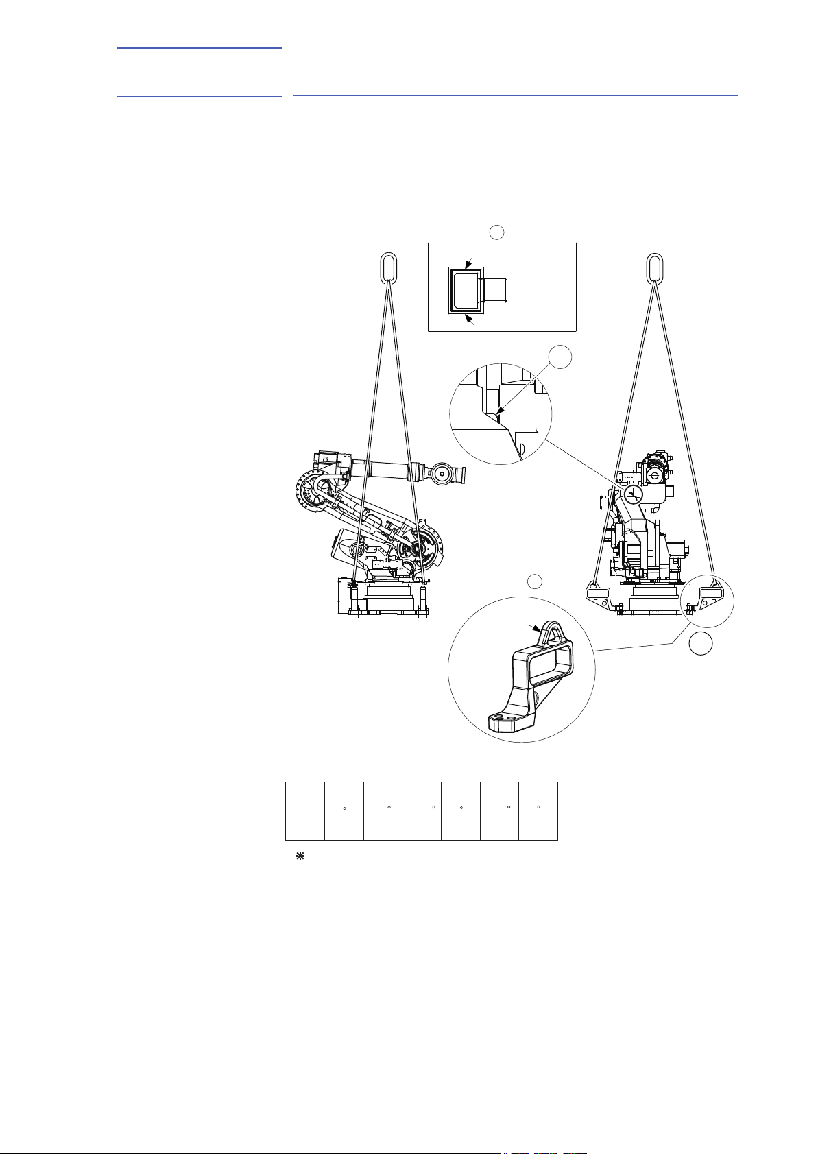
(1 piece)
Shipping bolt
Electrical tape
painted in yellow
Rubber plate
Details of B part
Hook
A
Shipping bracket
(4 pieces)
B
Details of A part
Axis
Angle
When equipped with external cablings,
those settings are subject to change depending on the specifications.
Pulse
L
RUBTS
0
-143518
-134502 0 -147520 0
0
-60
-63.9 0 -86.1 0
Factory setting for angle and pulse of each axis
19 of 92
ES165D
2 Transport
2.1 Transport Method
2.1.1 Using a Crane
As a rule, the manipulator should be lifted by a crane with four wire ropes
when removing it from the package and moving it. Be sure that the
manipulator is fixed with the shipping bolts and brackets before transport,
and lift it in the posture as shown in Fig. 2-1 “Transporting Position”.
Fig. 2-1: Transporting Position
2-2
HW0485249
Page 20
ES165D
NOTE
Hook
Electrical tape painted
in yellow
Rubber plate
B
A
Shipping bracket
Shipping bolt
20 of 92
155976-1CD
2 Transport
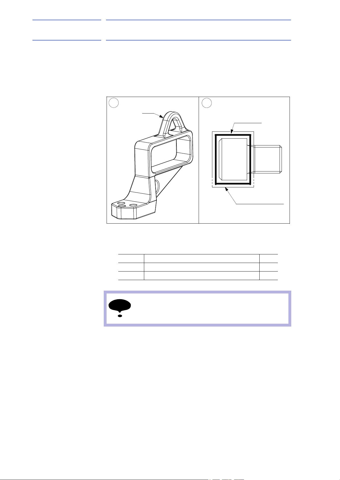
2.2 Shipping Bolts and Brackets
2.2 Shipping Bolts and Brackets
The manipulator is provided with shipping bolts and brackets at position A
and with the hexagon socket head cap screws at point B. (Fig. 2-1
“Transporting Position”).
Fig. 2-2: Shipping Bolts and Brackets
• The A-shipping brackets are painted in yellow.
• The B-shipping bolt: hexagon socket head cap screw is taped in
yellow.
Position Bolt Type Pcs
A Hexagon socket head cap screw M20 X 70 mm 12
B Hexagon socket head cap screw M16 X 20 mm 1
Before turning ON the power, check to be sure that the
shipping bolts and brackets are removed. The shipping
bolts and brackets then must be stored for future use, in the
event that the manipulator must be moved again.
2-3
HW0485249
Page 21
155976-1CD
CAUTION
21 of 92
ES165D
3 Installation
3 Installation
WARNING
• Install the safeguarding.
Failure to observe this warning may result in injury or damage.
• Install the manipulator in a location where the tool or the workpiece
held by its fully extended arm will not reach the wall, safeguarding,
or controller.
Failure to observe this warning may result in injury or damage.
• Do not start the manipulator or even turn ON the power before it is
firmly anchored.
The manipulator may overturn and cause injury or damage.
• Do not install or operate the manipulator that is damaged or lacks
parts.
Failure to observe this caution may cause injury or damage.
• Before turning ON the power, check to be sure that the shipping
bolts and brackets explained in Fig. 2-2 “Shipping Bolts and
Brackets” are removed.
Failure to observe this caution may result in damage to the driving
parts.
3-1
HW0485249
Page 22

ES165D
22 of 92
155976-1CD
3 Installation
3.1 Safeguarding Installation
3.1 Safeguarding Installation
To insure safety, be sure to install safeguarding. It prevents unforeseen
accidents with personnel and damage to equipment. Refer to the quoted
clause for your information and guidance.
Responsibility for Safeguarding (ISO10218)
The user of a manipulator or robot system shall ensure that safeguards
are provided and used in accordance with Sections 6, 7, and 8 of this
standard. The means and degree of safeguarding, including any
redundancies, shall correspond directly to the type and level of hazard
presented by the robot system consistent with the robot application.
Safeguarding may include but not be limited to safeguarding devices,
barriers, interlock barriers, perimeter guarding, awareness barriers, and
awareness signals.
3.2 Mounting Procedures for Manipulator Base
The manipulator should be firmly mounted on a baseplate or foundation
strong enough to support the manipulator and withstand reaction forces
during acceleration and deceleration.
Construct a solid foundation with the appropriate thickness to withstand
maximum reaction forces of the manipulator referring to Table 3-1
"Maximum Reaction Forces of the Manipulator at Emergency Stop" and
Table 3-2 "Endurance Torque in Operation".
A baseplate flatness must be kept at 0.5 mm or less: insufficient flatness
of installation surface may deform the manipulator shape and affect its
functional abilities. Mount the manipulator base as instructed in section
3.2.1 “Mounting Example”.
Table 3-1: Maximum Reaction Forces of the Manipulator at Emergency
Stop
Maximum torque in horizontal rotation
(S-axis moving direction)
Maximum torque in vertical rotation
(L-, U-axes moving direction)
32000 N•m
(3265 kgf•m)
78500 N•m
(8000 kgf•m)
Table 3-2: Endurance Torque in Operation
Endurance torque in horizontal operation
(S-axis moving direction)
Endurance torque in vertical operation
(L-, U-axes moving direction)
3-2
9400 N•m
(960 kgf•m)
23900 N•m
(2434 kgf•m)
HW0485249
Page 23
155976-1CD
40
Baseplate
Manipulator base
Spring washer
Washer
Flatness: 0.5mm or less
Hexagon socket head cap screw
M20 (8 screws)
Units: mm
23 of 92
ES165D
3 Installation
3.3 Location
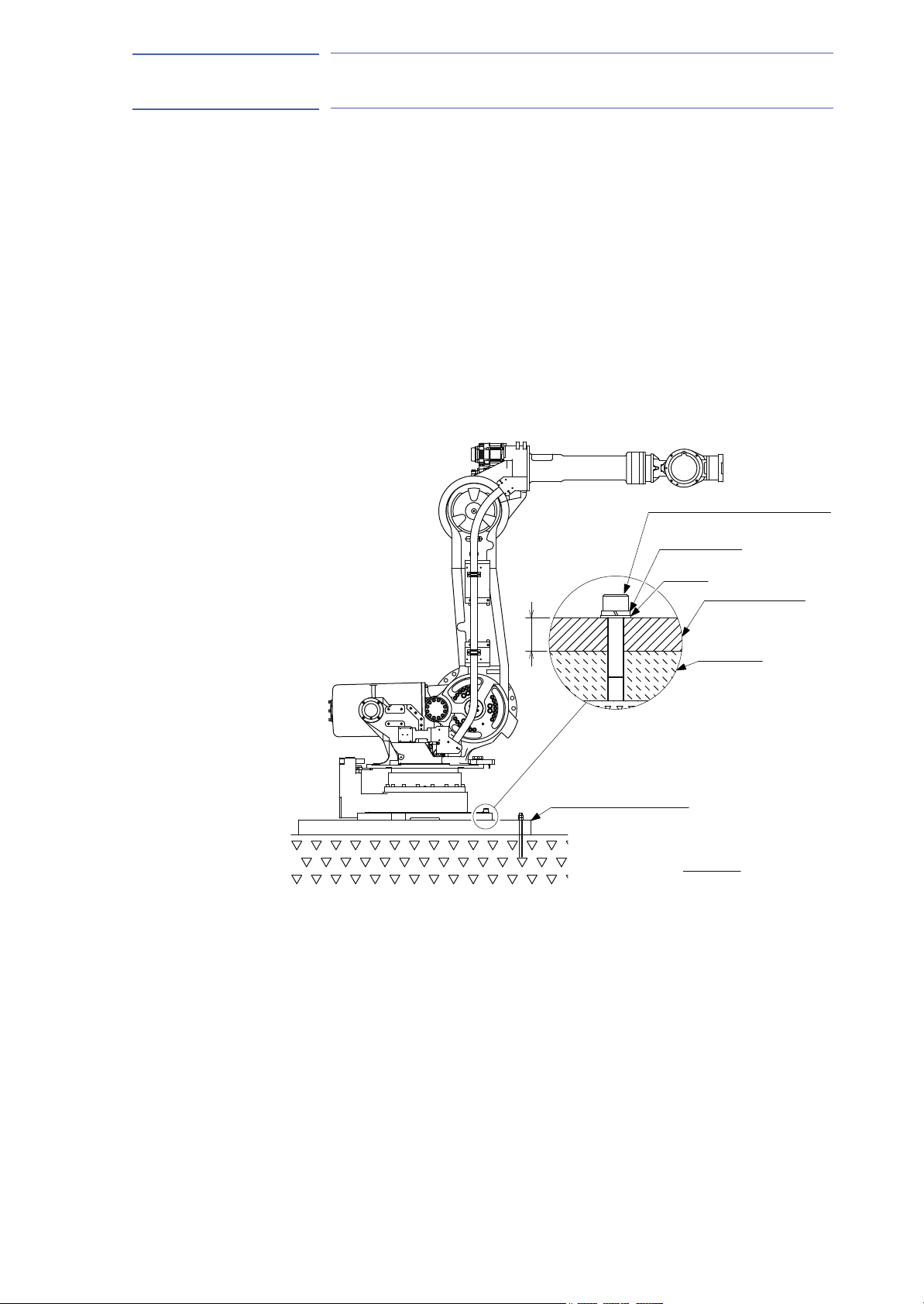
3.2.1 Mounting Example
For the first process, anchor the baseplate firmly to the ground. The
baseplate should be rugged and durable to prevent shifting of the
manipulator or the mounting fixture. It is recommend to prepare a
baseplate of 50 mm or more thick, and anchor bolts of M20 or larger size.
The manipulator base is tapped for eight mounting holes; securely fix the
manipulator base to the baseplate with eight hexagon head bolts M20
(80 mm long is recommended).
Next, fix the manipulator base to the baseplate. Tighten the hexagon
head bolts and anchor bolts firmly so that they will not work loose during
the operation.
Refer to Fig. 3-1 “Mounting the Manipulator on Baseplate”.
Fig. 3-1: Mounting the Manipulator on Baseplate
3.3 Location
When the manipulator is installed, it is necessary to satisfy the following
environmental conditions:
• Ambient temperature: 0° to + 45°C
• Humidity: 20 to 80%RH (at constant temperature)
• Free from dust, soot, or water
• Free from corrosive gases or liquids, or explosive gases
• Free from excessive vibration
(Vibration acceleration: 4.9 m/s
2
or less [0.5 G] or less)
• Free from large electrical noise (plasma)
• Flatness for installation: 0.5 mm or less
3-3
HW0485249
Page 24
ES165D
CAUTION
NOTE
A
5.5mm2 or more
View A
Delivered with manipulator
Bolt M8 (for grounding)
24 of 92
4 Wiring
155976-1CD
4 Wiring
4.1 Grounding
WARNING
• Ground resistance must be 100 Ω or less.
Failure to observe this warning may result in fire or electric shock.
• Before wiring, make sure to turn the primary power supply off, and
put up a warning sign. (ex. DO NOT TURN THE POWER ON.)
Failure to observe this warning may result in fire or electric shock.
• Wiring must be performed by authorized or certified personnel.
Failure to observe this caution may result in fire or electric shock.
• Do not cover the cable or allow it to tangle. Keep the cable as
straight as possible.
Failure to observe this caution may result in preventing heat of the
cable from being discharged.
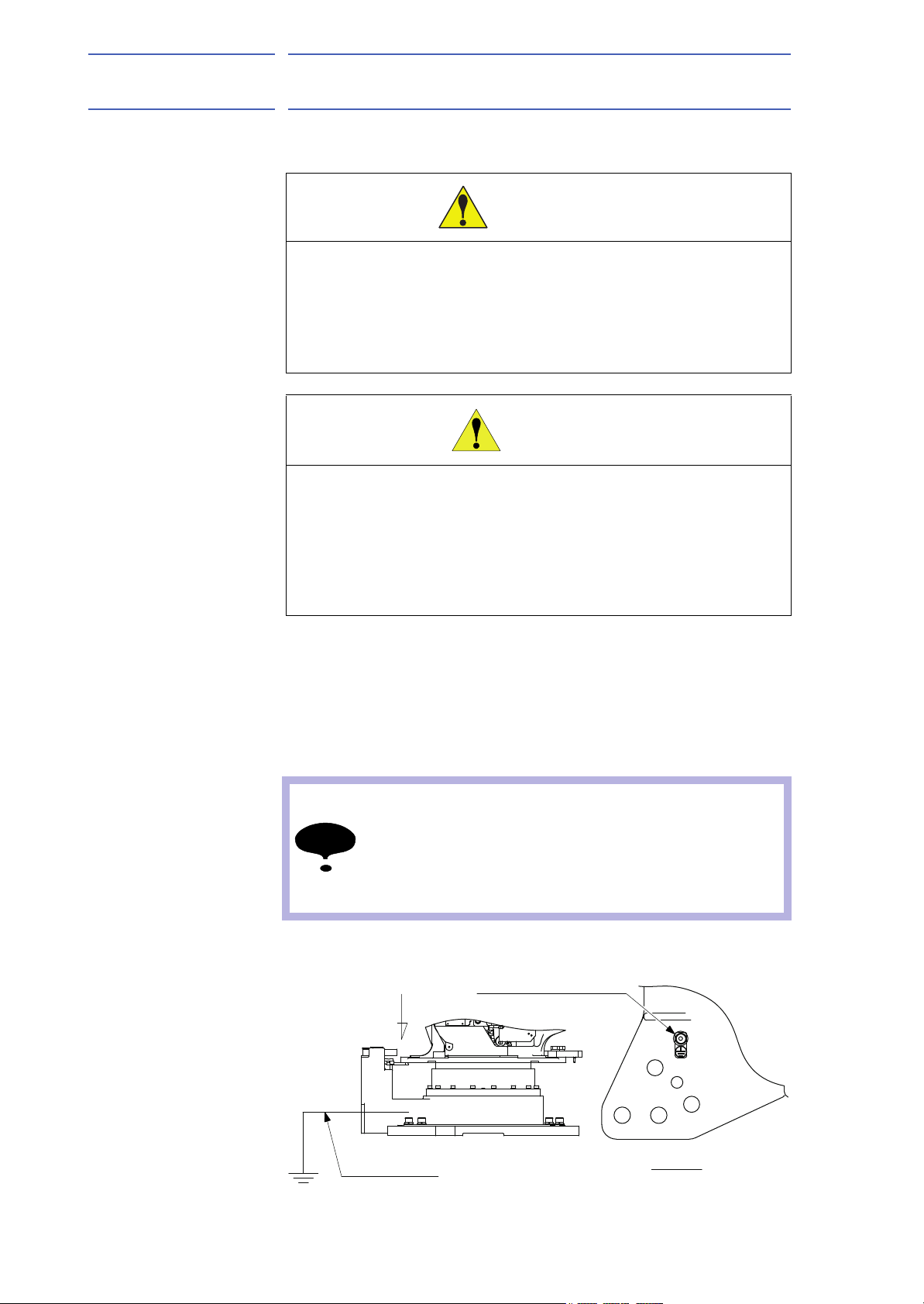
4.1 Grounding
Follow electrical installation standards and wiring regulations for
grounding. A ground wire of 5.5 mm
Refer to Fig. 4-1 “Grounding Method” to connect the ground line directly to
the manipulator.
2
or more is recommended.
• Never use this wire sharing with other ground lines or
grounding electrodes for other electric power, motor
power, welding devices, etc.
• Where metal ducts, metallic conduits, or distributing racks
are used for cable laying, ground in accordance with
electrical installation standards.
Fig. 4-1: Grounding Method
4-1
HW0485249
Page 25

155976-1CD
25 of 92
ES165D
4 Wiring
4.2 Cable Connection
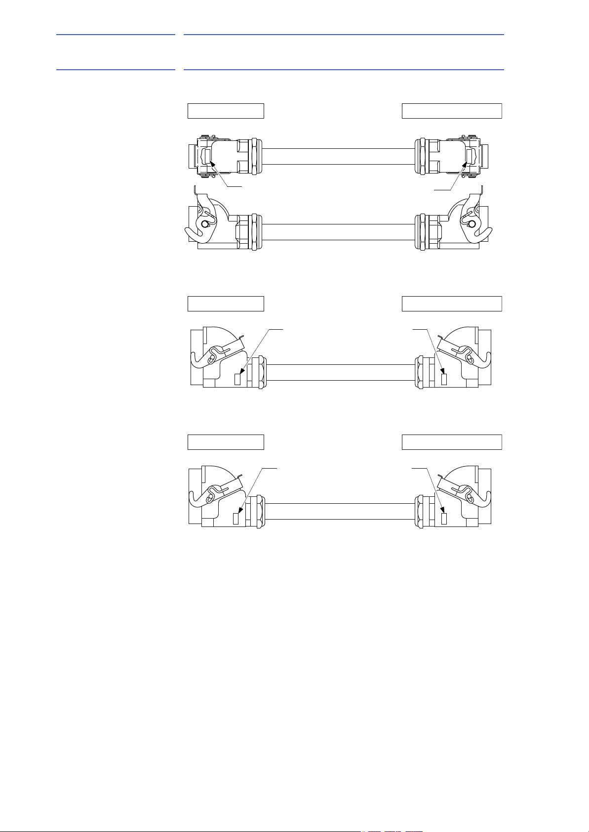
4.2 Cable Connection
Three manipulator cables are delivered with the manipulator; an encoder
cable for detection (1BC) and two power cables (2BC and 3BC). (Refer to
Fig. 4-2 “Manipulator Cables”.)
Connect these cables to the manipulator base connectors and to the
DX100. Refer to Fig. 4-3(a) “Manipulator Cable Connectors (Manipulator
Side)” and Fig. 4-3(b) “Manipulator Cable Connection (DX100 Side)” .
4.2.1 Connection to the Manipulator
Before connecting three cables to the manipulator, verify the numbers on
both manipulator cables and the connectors on the connector base of the
manipulator. When connecting, adjust the cable connector positions to
the main key positions of the manipulator, and insert cables in the order of
2BC, 1 BC, then 3BC. After inserting the cables, depress the lever until it
clicks.
4.2.2 Connection to the DX100
Before connecting cables to the DX100, verify the numbers on both
manipulator cables and the connectors on the DX100. When connecting,
insert the cables in the order of X21, X22, then X11, and depress each
lever low until it clicks.
4-2
HW0485249
Page 26
ES165D
X21
X22
3BC
3BC
2BC
1BC
X11
X11
1BC
1BC
2BC
2BC
X21
X22
3BC
The Manipulator SideThe DX100 Side
The Manipulator SideThe DX100 Side
The Manipulator SideThe DX100 Side
Encoder Cable
Power Cable
Power Cable
26 of 92
155976-1CD
4 Wiring
4.2 Cable Connection
Fig. 4-2: Manipulator Cables
4-3
HW0485249
Page 27
155976-1CD
1BC
3BC
S1
AIR
A
2BC
3BC
molexmolexmolex
1BC
2BC
Connector Details
(Manipulator Side)
Key positions
X22
X21
X11
27 of 92
ES165D
4 Wiring
4.2 Cable Connection
Fig. 4-3(a): Manipulator Cable Connectors (Manipulator Side)
Fig. 4-3(b): Manipulator Cable Connection (DX100 Side)
4-4
HW0485249
Page 28

ES165D
28 of 92
5 Basic Specifications
5.1 Basic Specifications
5 Basic Specifications
5.1 Basic Specifications
Table 5-1: Basic Specifications
Item Model MOTOMAN-ES165D MOTOMAN-ES165D
Structure Vertically Articulated
Degree of Freedom 6
Payload 165 kg
Repeatability
Range of Motion S-Axis (turning) -180° - +180°
Maximum Speed S-Axis 1.92 rad/s, 110°/s
Allowable Moment
Allowable Inertia (GD
Approx. Mass 1100 kg
Ambient Conditions Temperature 0° C to 45° C
Power Requirements 5.0 kVA
1 SI units are used in this table. However, gravitational unit is used in ( ).
2 Conformed to ISO9283
3 Refer to chapter 6.1 “Allowable Wrist Load” for details on the permissible moment of inertia.
2)
3)
2
/4) R-Axis 85 kg•m
1)
with external cabling for
SRBT-axes
±0.2 mm
L-Axis (lower arm) -60° - +76°
U-Axis (upper arm) -142.5° - +230°
R-Axis (wrist roll) -360° - +360° -205° - +205°
B-Axis (wrist pitch/yaw) -130° - +130° -120° - +120°
T-Axis (wrist twist) -360° - +360° -200° - +200°
L-Axis 1.92 rad/s, 110°/s
U-Axis 1.92 rad/s, 110°/s
R-Axis 3.05 rad/s, 175°/s
B-Axis 2.62 rad/s, 150°/s
T-Axis 4.19 rad/s, 240°/s
R-Axis 921 N•m (94 kgf•m)
B-Axis 921 N•m (94 kgf•m)
T-Axis 490 N•m (50 kgf•m)
2
B-Axis 85 kg•m
T-Axis 45 kg•m
Humidity 20 to 80% RH (non-condensing)
Vibration Acceleration 4.9 m/s
Others Free from corrosive gasses or liquids, or explosive
gasses
Free from exposure to water, oil, or dust
Free from excessive electrical noise (plasma)
2
2
2
or less (0.5 G)
155976-1CD
5-1
HW0485249
Page 29

155976-1CD
T+
T-
B-
B+
R+
R-
U-
U+
L- L+
S-
S+
350 0.1
290 0.1
290 0.1
640
290 0.1
893
290 0.1
540
290 0.1290 0.1
540
640
735
353 0.1
40
A
View A
22 dia. (8 holes)
(For fixing the manipulator)
Units: mm
Fitting surface
Fitting surface
20 dia. (2 holes)
(Pin hole for manipulator
positioning)
+0.021
0
16 dia. (2 holes)
(Pin hole for manipulator
positioning)
+0.018
0
29 of 92
ES165D
5 Basic Specifications
5.2 Part Names and Working Axes
5.2 Part Names and Working Axes
Fig. 5-1: Part Names and Working Axes
5.3 Manipulator Base Dimensions
Fig. 5-2: Manipulator Base Dimensions
5-2
HW0485249
Page 30

ES165D
491
294
180
180
3050
142.5
495
348
1024
650
0
322
16
R729
R2651
2651
491
1961
4612
2251225
76
285
25
42
153
250
50
650
1150
60
729
727
582
701
524
0
A
945
40
2203
126
687
0
1307
R608R608
18
P-point
P-point maximum
envelope
View A
Note:
This figure shows the standard specification manipulator in the home position.
30 of 92
5 Basic Specifications
5.4 Dimensions and P-Point Maximum Envelope
5.4 Dimensions and P-Point Maximum Envelope
Fig. 5-3: Dimensions and P-Point Maximum Envelope
155976-1CD
5-3
HW0485249
Page 31

155976-1CD
NOTE
31 of 92
ES165D
5 Basic Specifications
5.5 Alterable Operating Range
5.5 Alterable Operating Range
The operating range of the S-axis can be altered in accordance with the
operating conditions as shown in Table 5-2 "S-Axis Operating Range".
If alteration is necessary, contact your YASKAWA representative in
advance.
Table 5-2: S-Axis Operating Range
Item Specifications
S-Axis Operating
Range
-180° - +180° (standard)
*(-165° - +165°)
-150° - +150°
-135° - +135°
-120° - +120°
-105° - +105°
-90° - +90°
-75° - +75°
-60° - +60°
-45° - +45°
-30° - +30°
*(-15° - +15°)
* The interval between stoppers must be 60° or more.
When altering the operating range to ±15° or ±165°, please
contact your YASKAWA representative.
5-4
HW0485249
Page 32

ES165D
A
A
HW0302424-2
HW0402104-1
Section A-A
Pin
Flat washer M20
Hexagon socket head cap screws M20 (3 screws)
(length: 45) (tightening torque: 12.9)
Stopper
32 of 92
155976-1CD
5 Basic Specifications
5.5 Alterable Operating Range
5.5.1 Components for Altering Operating Range
Arrange the components listed in Fig. 5-4 “The Components of the S-Axis
Stopper”, when modifying the angle of S-axis.
(1) Pin (drawing No. HW0402104-1, 1 pin)
(2) Stopper (drawing No. HW0302424-2, 1 stopper)
(3) Hexagon socket head cap screw M20
(length: 45 mm) (3 screws) (tightening torque: 402 N•m)
(4) Flat washer M20 (3 flat washers)
Fig. 5-4: The Components of the S-Axis Stopper
5-5
HW0485249
Page 33

155976-1CD
Improperly-mounted
Properly-mounted
Hexagon socket
head cap scerws
Hexagon socket
head cap scerws
NOTE
33 of 92
ES165D
5 Basic Specifications
5.5 Alterable Operating Range
5.5.2 Notes on the Mechanical Stopper Installation
• For S-Axis mechanical stopper, install the stopper (drawing No.
HW0302424-2) with the pin which is used bottom up (drawing No.
HW0402104-1) as in Fig. 5-4 “The Components of the S-Axis
Stopper”.
• DO NOT forget to apply the locktite 242 to the thread part of pin before
inserting it into the stopper.
• Mount the stopper to the S-head with three hexagon head screws M20
(length: 45 mm) and tighten the screws to the tightening torque of 402
N•m (tensile strength: 1200 N/mm
2
or more). The stopper is to be
installed as shown in the Fig. 5-4 “The Components of the S-Axis
Stopper” when the operating range is ±180°.
• The stopper can be installed by every 15 degree pitch, however, to
avoid the mechanical troubles caused by interference between
stoppers (e.g. ±15°, ±165°), install the S-axis mechanical stopper
referring to Table 5-3 "The settable angle for S-Axis Stopper".
• Confirm to stabilize both sides of the protrusion with the hexagon
socket head cap screws as in Fig. 5-5 “Properly-Mounted Image” on
account of the limitation of strength to the unit.
• Refer to the figures: Fig. 5-6(a) to Fig. 5-6(g) as adjusting the setting
angle of the S-Axis mechanical stopper. When mounting the S-Axis
mechanical stopper by inverse angle to the examples in the figures:
Fig. 5-6(a) to Fig. 5-6(g) , settle the machinery symmetrical to those
models.
• As in the figures: Fig. 5-6(a) to Fig. 5-6(g) , the component is reversible
that both sides of the machinery can be attached to the stopper,
except for the angles of ±30, ±60, ±120, ±150 degrees. Flip side and
retry installing the S-Axis mechanical stopper if finding any difficulty to
set the machinery to the stopper based on Fig. 5-4 “The Components
of the S-Axis Stopper”.
Fig. 5-5: Properly-Mounted Image
1. Apply the specified components when mounting the
2. TURN OFF the electric power supply before mounting.
S-Axis mechanical stopper.
5-6
HW0485249
Page 34

ES165D
NOTE
34 of 92
5.5.3 Adjustment to the Pulse Limitation of S-Axis
Degree ±0°∗(±15°) ±30°±45°±60°±75°±90°
5 Basic Specifications
5.5 Alterable Operating Range
To limit the operating range of the S-axis, refer to DX100 Instructions
section 8.17 “Changing the Parameter Setting (162536-1CD)” and
change the following parameters with the programming pendant.
The limitation to the pulse (Pulse Soft Limit + 1st Axis ) : SICxG400
The limitation to the pulse (Pulse Soft Limit - 1st Axis ) : SICxG408
155976-1CD
Number
of Pulse
Degree ±105°±120°±135°±150°∗(±165°) ±180° (Standard)
Number
of Pulse
±0 ±35840 ±71680 ±107520 ±143360 ±179200 ±215040
±250880 ±286720 ±322560 ±358400 ±394240 ±430080
* Refer to section 5.5 “Alterable Operating Range”.
Adjust both of the pulse limitation and the angle of S-Axis
mechanical stopper as modifying the range of motion for
machinery.
5-7
HW0485249
Page 35

155976-1CD
"Table 5-3 The Settable Angle for S-Axis Stopper" indicates the angle range
which allows S-axis to be set for + direction and - direction angles.
35 of 92
ES165D
5 Basic Specifications
5.5 Alterable Operating Range
Table 5-3: The settable angle for S-Axis Stopper
The Angle of S-Axis Stopper for + Direction
180 165 150 135 120 105 90 75 60 45 30 15 0 -15 -30 -45 -60 -75 -90 -105 -120 -135 -150 -165 -180
-90
-75
-60
-45
-180
-165
-150
-135
-120
-105
-30
-15
0
1530456075
Settable angle
Non settable angle
90
105
120
135
150
165
180
The Angle of S-Axis Stopper for - Direction
5-8
HW0485249
Page 36

ES165D
The stopper is reversible.
Either side of the stopper can be used.
Installation at + 180°
Hexagon head screws
Installation at + 165°
The stopper is reversible.
Either side of the stopper can be used.
Hexagon head screws
36 of 92
155976-1CD
5 Basic Specifications
5.5 Alterable Operating Range
Fig. 5-6(a): The Properly-Mounted Models for S-Axis Stopper
5-9
HW0485249
Page 37

155976-1CD
The stopper is reversible.
Either side of the stopper can be used.
Hexagon head screws
Hexagon head screws
Installation at + 150°
Installation at + 135°
The stopper is irreversible.
Only this side of the stopper can be used at this angle.
37 of 92
ES165D
5 Basic Specifications
5.5 Alterable Operating Range
Fig. 5-6(b): The Properly-Mounted Models for S-Axis Stopper
5-10
HW0485249
Page 38

ES165D
The stopper is reversible.
Either side of the stopper can be used.
Hexagon head screws
Installation at + 120°
The stopper is irreversible.
Only this side of the stopper can be used at this angle.
Installation at + 105
Hexagon head screws
38 of 92
155976-1CD
5 Basic Specifications
5.5 Alterable Operating Range
Fig. 5-6(c): The Properly-Mounted Models for S-Axis Stopper
5-11
HW0485249
Page 39

155976-1CD
The stopper is reversible.
Either side of the stopper can be used.
Hexagon head screws
Installation at + 90°
Installation at + 75°
Hexagon head screws
The stopper is reversible.
Either side of the stopper can be used.
39 of 92
ES165D
5 Basic Specifications
5.5 Alterable Operating Range
Fig. 5-6(d): The Properly-Mounted Models for S-Axis Stopper
5-12
HW0485249
Page 40

ES165D
The stopper is reversible.
Either side of the stopper can be used.
Hexagon head screws
Installation at + 60°
The stopper is irreversible.
Only this side of the stopper can be used at this angle.
Installation at + 45°
Hexagon head screws
40 of 92
155976-1CD
5 Basic Specifications
5.5 Alterable Operating Range
Fig. 5-6(e): The Properly-Mounted Models for S-Axis Stopper
5-13
HW0485249
Page 41

155976-1CD
The stopper is reversible.
Either side of the stopper can be used.
Installation at + 30°
The stopper is irreversible.
Only this side of the stopper can be used at this angle.
Hexagon head screws
Installation at + 15°
Hexagon head screws
The stopper is reversible.
Either side of the stopper can be used.
Installation at 0°
Hexagon head screws
41 of 92
ES165D
5 Basic Specifications
5.5 Alterable Operating Range
Fig. 5-6(f): The Properly-Mounted Models for S-Axis Stopper
Fig. 5-6(g): The Properly-Mounted Models for S-Axis Stopper
5-14
HW0485249
Page 42

ES165D
42 of 92
6 Allowable Load for Wrist Axis and Wrist Flange
6.1 Allowable Wrist Load
6 Allowable Load for Wrist Axis and Wrist Flange
6.1 Allowable Wrist Load
The allowable wrist load including the weight of the mount/gripper
is:
• YR-ES0165D-A00, -A01: 165kg maximum
If force is applied to the wrist instead of the load, force on R-, B-, and
T
-axes should be within the value shown in Table 6-1 "Allowable Wrist
Load". Contact your YASKAWA representative for further information or
assistance.
Table 6-1: Allowable Wrist Load
Axis Moment N•m (kgf•m)
R-Axis 921 (94) 85
B-Axis 921 (94) 85
T-Axis 490 (50) 45
1 ( ): Gravitational unit
1)
2
/4 Total Moment of Inertia kg•m
GD
155976-1CD
2
When the volume load is small, refer to the moment arm rating shown in
Fig. 6-1 “Moment Arm Rating”.
The allowable total moment of inertia is calculated when the moment is at
the maximum. Contact your YASKAWA representative beforehand when
only moment of inertia, or load moment is small and moment of inertia is
large. Also, when the load mass is combined with an outside force,
contact your YASKAWA representative beforehand.
6-1
HW0485249
Page 43

155976-1CD
1400
1200
1000
800
800
1000
40kg
60kg
80kg
1000
600
130kg
400
100kg
800 LB(mm)
600
400
LT(mm)
200
200
400
600
LT(mm)
165kg
P-point
T-, R-axis
center of rotation
B-axis center of rotation
43 of 92
ES165D
6 Allowable Load for Wrist Axis and Wrist Flange
6.1 Allowable Wrist Load
Fig. 6-1: Moment Arm Rating
6-2
HW0485249
Page 44

ES165D
8
8
P.C.D.125
P.C.D.92
Units: mm
9 dia.
(2 holes) (depth: 8 mm)
10 dia.
(2 holes) (depth: 8 mm)
Alignment
mark
63 dia.
+0.030
0
160 dia.
0
-0.025
+0.018
0
+0.015
0
Tapped hole M10
(6 holes) (depth: 12 mm)
Tapped hole M10
(6 holes) (depth: 12 mm)
NOTE
44 of 92
155976-1CD
6 Allowable Load for Wrist Axis and Wrist Flange
6.2 Wrist Flange
6.2 Wrist Flange
The wrist flange dimensions are shown in Fig. 6-2 “Wrist Flange”. It is
recommended that the attachment be mounted inside the fitting in order to
identify the alignment marks. Fitting depth of inside and outside must be
8 mm or less.
Fig. 6-2: Wrist Flange
Wash off anti-corrosive paint (yellow) on the wrist flange
surface with thinner or light oil before mounting the tools.
6-3
HW0485249
Page 45

155976-1CD
120
40 255
133
120
255
153
40
25540
30
117
73
50
120
133
120
255
40
137.5
85
75
5
85
5
75 137.5
153
B
50 30
73117
B
A1
A2
Tapped hole M12
(4 holes) (depth: 24mm)
Tapped hole M12
(4 holes) (depth: 24mm)
Tapped hole M8
(4 holes) (depth: 15mm)
Tapped hole M8
(4 holes) (depth: 15mm)
45 of 92
ES165D
7 System Application
7.1 Peripheral Equipment Mounts
7 System Application
7.1 Peripheral Equipment Mounts
The peripheral equipment mounts are provided on the U-axis (upper arm)
and S-axis (rotary head) as shown in Fig. 7-1 “Installing Peripheral
Equipment” for easier installation of the user's system applications.
The following conditions shall be observed to attach or install peripheral
equipment. (Refer to Table 7-1 "Conditions for Installation".)
Fig. 7-1: Installing Peripheral Equipment
Table 7-1: Conditions for Installation
Application Note
A1, A2 Cable Processing
and Valve Load
30 kg max.
49 N•m (5 kgf•m) max. for moment increase
amount of upper arm
B Others 250 kg max.
7-1
HW0485249
Page 46

ES165D
46 of 92
155976-1CD
7 System Application
7.2 Internal User I/O Wiring Harness and Air Line
7.2 Internal User I/O Wiring Harness and Air Line
6 cables for valves (0.75 mm2), 18 internal user I/O wires (0.5 mm2 x
6 wires, 0.75 mm
x 7 cables, 0.75 mm
2
x 12 wires), the cables for the external axis (1.25 mm2
2
x 2 cables, 0.2 mm2 x 4 cables), and an air line are
used in the manipulator for the drives of peripheral devices mounted on
the upper arm as shown in Fig. 7-2 “Connectors for Internal User I/O
Wiring Harness and Air Line”.
The connector pins, and the terminals are assigned as shown in Fig. 7-2
“Connectors for Internal User I/O Wiring Harness and Air Line” and
Fig. 7-3 “Details of the Connector Pin Numbers”. Wiring must be
performed by users.
The allowable current for internal user
I/O wiring harness
The maximum pressure for the air line 490 kPa (5 kgf/cm2) or less
8.0A or less / wire. (1.25 mm2)
2
5.0A or less / wire. (0.75 mm
3.5A or less / wire. (0.5 mm
2.8A or less / wire. (0.3 mm
2.3A or less / wire. (0.2 mm
(The air line inside diameter: 8.0 mm )
)
2
)
2
)
2
)
7-2
HW0485249
Page 47

155976-1CD
3BC
AIR
S1
1BC
2BC
Tapped holes PT3/8
with pipe plug
Exhaust port (air flow)
Connector for the external axis
(Power cable):
JL05-2A18-1SC
(socket connector with cap).
Prepare pin connector: JL05-6A18-1P
.
Connector for internal user
I/O wiring harness (Casing):
JL05-2A22-14SC
(socket connector with cap).
Prepare pin connector: JL05-6A22-14P
.
JL05-2A20-29SC
(socket connector with cap).
Prepare pin connector: JL05-6A20-29P.
Connector for the external axis (Encoder cable):
Key position
Key position
T
apped holes PT3/8 with pipe plug
Air inlet (air flow)
JL05-2A28-21PC (pin connector with cap).
Prepare socket connector: JL05-6A28-21S.
Connector for internal user
I/O wiring harness (Base):
View A
47 of 92
ES165D
Fig. 7-2: Connectors for Internal User I/O Wiring Harness and Air Line
7 System Application
7.2 Internal User I/O Wiring Harness and Air Line
7-3
HW0485249
Page 48

ES165D
43
22
14
21
13
20
2726
32
33
15
28
9
8
21
1211
18
2524
30
35
10
16
23
29
34
17
567
36
31
19
3
2
1
6
4
5
P
P
P
7
8
10
11
9
13
14
16
17
15
19
20
21
18
12
76
11312
1615
54
918
1413
17 18
10
2
1
2
5
4
3
P
P
8
7
11
10
9
P
6
13
14
15
16
17
18
12
6
10
3
8
5
1
2
7
4
9
14
16
1211
15
13
1
2
P
P
10
15
9
21
4
7
5
8
3
9
6
2
1
5
4
6
3
0.3mm2
(12 pins)
0.75mm
2
(6 pins)
0.2mm
2
(4 pins)
1.25mm
2
(4 pins)
0.75mm
2
(2 pins)
0.5mm
2
(6 pins)
0.3mm
2
(12 pins)
22
23
24
8
7
9
1.25mm2
(3 pins)
0.5mm
2
(6 pins)
Pins used
Pins used
Pins used
Pins used
Shielded wire
Pin details for internal user I/O wiring harness
(Base side)
Pin details for internal user I/O wiring harness
(Casing side)
Pin details for external axis encoder cable
Pin details for external axis power cable
48 of 92
7 System Application
7.2 Internal User I/O Wiring Harness and Air Line
Fig. 7-3: Details of the Connector Pin Numbers
7-4
155976-1CD
HW0485249
Page 49

155976-1CD
NOTE
L- and U-axes interference
limit switch
L-axis overrun
limit switch
S-axis overrun
limit switch
49 of 92
ES165D
8 Electrical Equipment Specification
8.1 Position of Limit Switch
8 Electrical Equipment Specification
8.1 Position of Limit Switch
8.1.1 Specification of Limit Switch
1. The interference limit switch at S-, L- and U-axes electrically limit the
operating range of respective axes by adjusting the position of the dog
using the limit switch.
The positions of the mechanical limits (mechanical stoppers) at S-, Land U-axes are changeable.
When the limit switch is activated, the power supply to the manipulator
is interrupted, then the manipulator makes an emergency stop as a
result. Refer to section 8.9 “Overrun/Tool Shock Sensor Releasing” in
“DX100 INSTRUCTIONS” for releasing the status of this overrun.
2. The range of S-, L- and U-axes limit switches are set to the maximum
operating range before shipping.
In case of re-adjusting the operating range of each subject
axis, it is also required to change the dog location and limit
values in software. Contact your YASKAWA representative
if re-adjustment is required.
8.1.2 Location of Limit Switch
The limit switch is optional. For the S-, L-, and U-axes with limit switch
specifications, the limit switch is located on S-, L-, and U-axis respectively.
For their locations, refer to Fig. 8-1 “Location of Limit Switch”.
Fig. 8-1: Location of Limit Switch
8-1
HW0485249
Page 50

ES165D
Negative side Positive side
61
77
L-axis center of rotation
50 of 92
155976-1CD
8 Electrical Equipment Specification
8.1 Position of Limit Switch
8.1.3 Setting of Operation Range
8.1.3.1 S-Axis Operation Range
By the S-axis limit switch, S-axis operation range can be set to those
ranges mentioned in Table 5-2 "S-Axis Operating Range".
8.1.3.2 L-Axis Operation Range
By the L-axis limit switch, the L-axis operation range can be set to any
angles within -61° to +77° as mentioned in the figure below.
Fig. 8-2: L-Axis Overrun Limit Switch Setting Range
8-2
HW0485249
Page 51

155976-1CD
280
U-axis center of rotation
51 of 92
ES165D
8 Electrical Equipment Specification
8.1 Position of Limit Switch
8.1.3.3 Setting Range of LU-Axes Interference Angle
L- and U-axes interference limit switches are designed to check the
interference angle of L- and U-axes.
As shown in Fig. 8-3 “LU-Axes Interference Angle”, the operation range of
U-axis can be set to any angles within -8° to +280° as the interference
angle with L-axis.
Fig. 8-3: LU-Axes Interference Angle
8-3
HW0485249
Page 52

ES165D
2BC
3BC
1BC
Connector for
Internal user I/O
wiring harness
(Base)
Connector for external axis
(Power cable)
Connector for external axis
(Encoder cable)
Connector for internal user
I/O wiring harness (Casing)
52 of 92
155976-1CD
8 Electrical Equipment Specification
8.2 Internal Connections
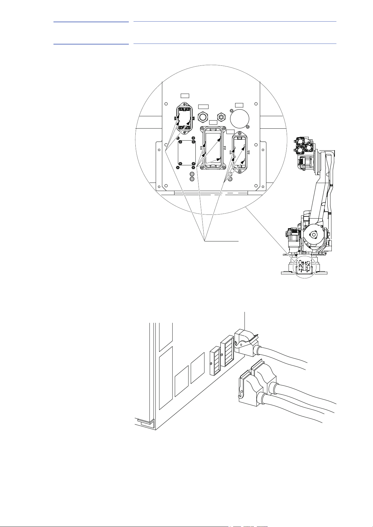
8.2 Internal Connections
Highly reliable connectors are equipped on each connection part of the
manipulator to enable easy removal and installation for maintenance and
inspection. For the number and location of connectors, see Fig. 8-4
“Locations and Numbers of Connectors”.
Diagrams for Internal connections of the manipulator are shown in Fig.
8-5(a) “Internal Connection Diagram” and Fig. 8-5(b) “Internal Connection
Diagram”.
Fig. 8-4: Locations and Numbers of Connectors
Table 8-1: List of Connector Types
Connector Base Connector for internal
U-arm Connector for internal
Name Type of Connector
JL05-2A28-21PC
user I/O wiring harness
user I/O wiring harness
Connector for external axis
(Encoder cable)
Connector for external axis
(Power cable)
8-4
(JL05-6A28-21S: Optional)
JL05-2A22-14SC
(JL05-6A22-14P: Optional)
JL05-2A20-29SC
(JL05-6A20-29P: Optional)
JL05-2A18-1SC
(JL05-6A18-1P: Optional)
HW0485249
Page 53

T-AXIS
B-AXIS
R-AXIS
U-AXIS
L-AXIS
E
E
E
E
LD1
+24
B3
B2
B1
A3
A2
A1
E E E E E E E
LD1
+24
0V
LC1
LD1
LB2
LB1
LD1
LD2
LA3
LB3
LD3
LC3
CN4-10
CN4-10
0V
23
24
22
SP22
SP23
SP24
P
P
P
P
P
P
0BAT6
BAT6
PG5V6
T
-1
-2
-3
No.21CN
-4 PG0V6
0BAT5
BAT5
PG5V5
B
-1
-2
-3
No.20CN
-4 PG0V5
R
0BAT4
PG0V4
PG5V4
BAT4
-4
-3
-2
-1
No.19CN
U
0BAT3
PG0V3
PG5V3
BAT3
-4
-3
-2
-1
No.18CN
L
0BAT2
PG0V2
PG5V2
BAT2
-4
-3
-2
-1
No.17CN
S
0BAT1
BAT1
PG5V1
PG0V1
-1
-2
-3
-4
No.16CN
X
0V
+24V
0V
+24V
No.22CN
-2
-4
-1
-3
-6
-5
-4
-9
-6
-5
-4
-9
-6
-5
-4
-9
-6
-5
-4
-9
-6
-5
-4
-9
-9
-4
-5
-6
LA1
E
E
S-AXIS
PG
DATA-1
DATA+1
-2
0V
BAT
OBT
+5V
1CN-1
No.1CN
0BAT2
0BAT3
BAT2
BAT3
BAT1
18
19
21
22
20
0BAT4
0BAT5
0BAT6
BAT5
BAT4
24
25
28
29
27
26
23
17
0BAT1
BAT
0BT
BATPP
4
2
3
BAT11
0BAT12
BAT12
0BT
0BT
BATP
BATP
6
8
7
5
0BAT21
BAT22
0BAT22
BAT21
0BAT11
1
0BT
BAT6
PG0V2
PG5V1
PG0V1
30
31
3
2
1
32
PG0V3
PG0V5
PG0V4
PG5V4
PG5V3
5
9
7
8
6
4 PG5V2
P
P
P
PG5V6
PG0V6
12
11
16
15
14
13
10 PG5V5
1
2
5
4
3
8
7
6
1BC(10P 4)
3
1
4
2
0V
+24V
0V
+24V
SPG-1
SPG+1
CN1-5
CN1-2
CN1-1
CN1-9
CN1-10
CN1-4
PG
PG
DATA+2
FG1
BAT
OBT
-10
2CN-1
No.2CN
-10
BAT
0V
FG2
+5V
OBT
-2 DATA-2
DATA-3
DATA+3
-2
BAT
BAT
3CN-1
No.3CN
-10
OBT
0V
FG3
OBT
+5V
OBT
PG
PG
DATA+4
DATA-4-2
OBT
BAT
4CN-1
No.4CN
-10
OBT
BAT
FG4
0V
+5V
DATA+5
DATA-5
-2
0V
BA
T
OBT
+5V
5CN-1
DATA+6
-10
OBT
BAT
FG5
6CN-1
No.6CN
No.5CN
BAT
P
P
P
P
P
P
FG1
SPG+2
FG2
SPG-2
CN1-7
CN1-6
CN1-8
SPG-3
SPG+3
FG3
CN2-3
CN2-2
CN2-1
P
P
P
P
P
P
SPG+4
SPG-4
FG4
CN2-7
CN2-6
CN2-8
SPG-5
SPG+5
SPG+6
FG5
CN3-6
CN3-3
CN3-2
CN3-1
PG
No.7CN(20-29)
1
-10
BAT
0V
OBT
+5V
FG6
BAT
OBT
LA2
LB2
BC1
BC2
LD2
LC2
15
10
9
0V
5V
SPG-7
FG7
P
E
SP19
2
SPG+7
P
P
P
LB1
SS1
LB1
LB2
SS2
LD2
LD1
FG6
LB1
+24V
CN3-8
CN4-6
CN4-1
SS2
SPG+7
BC2
CN4-4
CN4-8
CN4-3
CN4-7
CN4-2
E
E
FG7
0V
0V
5V
5V
CN2-10
CN2-9
CN2-5
CN2-4
CN4-9
CN3-5
CN3-9
CN3-10
CN3-4
19
S1(28-21)
CN4-5
SPG-7
MANIPULATOR
P
SPG-6
CN3-7
-2 DATA-6
CN1-3
CN1-5
CN1-4
CN1-10
CN1-9
0V
0V
+24V
+24V
CN1-1
CN1-2
SPG-1
SPG+1
DX100
CN1-3
CN1-6
FG1
SPG+2
CN1-7
CN1-8
FG2
SPG-2
CN2-1
CN2-2
SPG-3
SPG+3
CN2-3
FG3
CN2-6
CN2-7
SPG+4
SPG-4
CN2-8
FG4
CN3-1
CN3-2
SPG+5
SPG-5
CN3-6
CN3-3
SPG+6
FG5
CN3-7
CN3-8
FG6
CN4-1
CN4-6
+24V
LB1
CN4-2
CN4-7
SS2
AL1
CN4-8
CN4-3
BC2
AL2
SPG+7
FG7
CN4-5
CN4-9
CN2-4
CN2-5
CN2-9
CN2-10
0V
CN3-10
CN3-9
CN3-5
0V
5V
5V
CN3-4
SPG-7
CN4-4
SPG-6
No.8CN(22-14)
3
2
1
SP1
SP2
SP3
SP6
7
8
9
SP7
SP8
6
5
SP5
SP4
4
13
14
15
16
12
11
SP12
SP13
SP14
SP15
SP11
SP10
18
SP18
SP17
17
SP16
10
SP9
SP20
SP21
P
P
P
1
2
21
6
8
7
4
5
3
20
12
13
15
14
10
11
18
17
16
9
B3
A3
B2
A2
B1
A1
LA3
LB3
LB2
LB1
LB1
LA1
LC3
LD3
LD2
LD1
LD1
LC1
LD1
LC2
LD2
LD2
LD1
LC1
LB1
LA2
LB2
LB2
LB1
LA1
Base
Casing
SLU-axes with Limit Switch Specification
Connected to
L AND U-AXIS INTERFERENCE L.S.
L-AXIS OVERRUN L.S.
S-AXIS OVERRUN L.S.
L AND U-AXIS INTERFERENCE L.S.
L-AXIS OVERRUN L.S.
S-AXIS OVERRUN L.S.
Connected to
Connected to
Connected to
Connected to
Connected to
1. For the limit switch specification, the connection of the section
Notes
A
B
parts are changed as follows:and
FOR LAMP (OPTION)
53 of 92
155976-1CD
ES165D
Fig. 8-5(a): Internal Connection Diagram
8-5
8 Electrical Equipment Specification
8.2 Internal Connections
HW0485249
Page 54

ES165D
T-AXIS
B-AXIS
R-AXIS
U-AXIS
L-AXIS
S-AXIS
1
8
7
2
4
9
3
EE
CN5-1
CN5-4
CN6-1
CN6-4
CN6-6
CN6-5
CN5-5
CN5-2
E
MU1
MU1
MW1
MV1
MV1
MV1
MU1
2BC(8PX5+12PX1)
CN1-7
CN1-6
CN1-5
CN2-1
CN1-3
CN1-2
CN1-1
MW1
ME1
ME1
ME1
BB1
MU2
MU2
BA1
CN6-2
CN2-6
CN2-5
CN2-3
CN2-4
CN1-4
CN1-8
CN6-1
CN2-2 MW1
MW2
MV2
MV2
MV2
ME2
ME2
ME2
MW2
MW2
CN3-8
CN3-4
CN2-8
CN3-7
CN3-6
CN3-5
CN3-3
CN3-2
CN3-1
BB2
MU3
MU3
MW3
MV3
MV3
MV3
MU3
CN4-2
CN4-1
CN6-4
CN5-1
CN4-7
CN4-6
CN4-5
CN4-3
CN6-3
BA2
MW3
ME3
ME3
ME3
BB3
BA4
BB4
BA5
BA3
CN6-6
CN5-3
CN6-5
CN5-4
CN4-8
CN4-4
CN6-7
CN6-8
CN6-9
BA6
BB6
MW4
MV4
MW4
MU4
MV4
MU4
3BC(6PX6)
CN2-2
CN2-1
CN1-5
CN1-4
CN1-2
CN1-1
CN6-11
CN6-12
CN6-10
BB5
CN5-2 MW3
CN2-7
MU2
E
No.15CN
5
6
ME4
ME4
MW5
ME5
MW5
MV5
MU5
MV5
MU5
CN1-6
CN1-3
CN3-1
CN3-3
CN3-2
CN2-6
CN2-3
CN2-5
CN2-4
MU6
MU6
ME6
ME6
MW6
MW6
MV6
MV6
CN4-6
CN4-5
CN4-3
CN4-2
CN4-4
CN4-1
CN3-5
CN3-4
CN3-6 ME5
MU7
MU7
MW7
MW7
MV7
MV7
CN6-5
CN6-6
CN6-4
CN6-1
CN5-4
CN5-1
BA7
BB7
ME7
CN5-3
CN5-6
CN5-5
CN5-2
ME7
CN1-1
CN1-2
E
MU1
MU1
CN1-7
CN1-6
CN1-5
CN2-1
MV1
MV1
MV1
MW1
MU1CN1-3
CN2-3
CN1-8
CN1-4
CN2-4
MW1
ME1
ME1
ME1
CN6-2
CN2-6
CN2-5
BB1
MU2
MU2
BA1
CN6-1
MW1CN2-2
CN3-3
CN3-1
CN3-2
CN3-5
MV2
MV2
MV2
MW2
CN3-7
CN2-8
CN3-4
CN3-8
MW2
ME2
ME2
ME2
MW2CN3-6
CN4-1
CN4-2
CN6-4
MU3
MU3
BB2
CN4-7
CN4-5
CN4-6
CN5-1
MV3
MV3
MV3
MW3
MU3CN4-3
BA2
CN6-3
CN5-3
CN4-4
CN4-8
CN5-4
MW3
ME3
ME3
ME3
CN6-9
CN6-7
CN6-8
CN6-6
BA5
BB4
BA4
BB3
BA3
CN6-5
CN6-11
CN6-12
BA6
BB6
CN2-2
CN1-5
CN2-1
CN1-2
CN1-4
CN1-1
MW4
MV4
MU4
MW4
MV4
MU4
CN6-10
BB5
MW3CN5-2
MU2
CN2-7
CN1-3
CN1-6
ME4
ME4
CN3-1
CN3-2
CN3-3
CN2-6
CN2-5
CN2-3
MW5
MV5
MU5
MV5
MW5
ME5
MU5CN2-4
CN3-5
CN3-4
MU6
MU6
CN4-5
CN4-4
CN4-3
CN4-2
CN4-6
MV6
MW6
MW6
ME6
ME6
MV6CN4-1
ME5CN3-6
MU7
MU7
MW7
MW7
MV7
MV7
CN5-6
CN5-3
BB7
BA7
ME7
PE
ME7
LB1
LA1
LD1
LC1
LD1
LC2
LD2
LD2
LD1
LC1
LB1
LA2
LB2
LB2
LB1
LA1
LA1
LC1
LD1
LD1
LC1
LB1
LB1
LA1
SM
MU1
MV1
MW1
-B
-C
9CN-A
No.9CN
YB
ME1
BB1
BA1
-D
-2
-1
SM
11CN-A
No.11CN
-C
-B
MV3
MW3
MU3
MV2
MU2
YB
ME2
BB2
BA2
MW2 SM
-B
10CN-A
-D
-2
-1
-C
No.10CN
YB
-D
-2
-1
ME3
BB3
BA3
SM
12CN-A
No.12CN
-B
-C
MU4
MW4
MV4
YB
SM
-2
-D
-1
BB4
BA4
ME4
13CN-A
No.13CN
-B
-C
-D
MV5
ME5
MW5
MU5
YB
YB
SM
-2 BB5
14CN-A
-D
-1
-2
-C
-B
ME6
BB6
BA6
MU6
MW6
MV6
No.14CN
-1 BA5
B2
B1
A2
A1
SL-axes with Limit Switch Specification
Connected to
L-AXIS OVERRUN L.S.
S-AXIS OVERRUN L.S.
L-AXIS OVERRUN L.S.
S-AXIS OVERRUN L.S.
Connected to
Connected to
Connected to
S-axis with Limit Switch Specification
B1
S-AXIS OVERRUN L.S. Connected to
A1
Connected toS-AXIS OVERRUN L.S.
54 of 92
155976-1CD
8 Electrical Equipment Specification
8.2 Internal Connections
Fig. 8-5(b): Internal Connection Diagram
8-6
HW0485249
Page 55

155976-1CD
CAUTION
NOTE
55 of 92
ES165D
9 Maintenance and Inspection
9.1 Inspection Schedule
9 Maintenance and Inspection
• Maintenance and inspection must be performed by specified
personnel.
Failure to observe this caution may result in electric shock or injury.
• For disassembly or repair, contact your YASKAWA representative.
• Do not remove the motor, and do not release the brake.
Failure to observe these safety precautions may result in death or
serious injury from unexpected turning of the manipulator's arm.
DANGER
WARNING
• Before maintenance or inspection, be sure to turn the main power
supply OFF, and put up a warning sign. (ex. DO NOT TURN THE
POWER ON.)
Failure to observe this warning may result in electric shock or injury.
• The battery pack must be connected before removing detection
connector when maintenance and inspection.
Failure to observe this caution may result in the loss of home position
data.
9.1 Inspection Schedule
Proper inspections are essential not only to assure that the mechanism
will be able to function for a long period, but also to prevent malfunctions
and assure safe operation. Inspection intervals are classified into six
levels as shown in Table 9-1 "Inspection Items".
In Table 9-1 "Inspection Items", the inspection items are categorized by
three types of operations: operations which can be performed by
personnel authorized by the user, operations to be performed by trained
personnel, and operations to be performed by service company
personnel. Only specified personnel shall perform the inspection work.
• The inspection interval depends on the total servo
operation time.
• For any different or special applications, the inspection
process should be developed on an case-by-case basis.
• For axes which are used very frequently (in handling
applications, etc.), it is recommended that inspections be
conducted at shorter intervals. Contact your YASKAWA
representative.
9-1
HW0485249
Page 56

Table 9-1: Inspection Items (Sheet 1 of 2)
56 of 92
1)
Items
1 Alignment mark
2 External lead
3 Working area and
manipulator
4 Motors for L- and U-axes
5 Baseplate mounting bolts
6 Cover mounting screws
9-2
7 S-,L-,U-axes motor connector
8 Connector base
9 Balancer
10 Wire harness in manipulator
(SLU-axis wires)
(RBT-axis wires)
11 Battery pack in manipulator
HW0485249
12 S-axis speed reducer,
S-axis gear
13 L-axis speed reducer,
14 U-axis speed reducer,
Schedule Method Operation Inspection
Charge
Daily
1000HCycle
6000HCycle
12000HCycle
24000H
36000H
•
•
•
•
•
•
•
•
•
•
•
••
••
••
Visual Check alignment mark accordance at the home position.
Check for damage.
Visual Check for damage and deterioration of leads.
Visual Clean the work area if dust or spatter is present. Check for damage and
outside cracks.
Visual Check for grease leakage.
Spanner
Wrench
Screwdriver,
Wrench
Manual Check for loose connectors and tighten if necessary.
Manual Check for loose connectors.
Grease Gun Supply grease. See Chap. section 9.3.5.
Visual,
Multimeter
•
Grease Gun Check for malfunction. (Replace if necessary.)
Grease Gun Check for malfunction. (Replace if necessary.)
Grease Gun Check for malfunction. (Replace if necessary.)
Tighten loose bolts. Replace if necessary.
Tighten loose bolts. Replace if necessary.
Check for conduction between the main connector of base and intermediate
connector with manually shaking the wires. Check for wear of protective
3)
spring.
Replace
Replace the battery pack when the battery alarm occurs or the manipulator
drove for 36000H.
Supply grease5). (6000H cycle) See section 9.3.1.
Replace grease
Supply grease
Replace grease
Supply grease
Replace grease
4)
5)
. (12000H cycle) See section 9.3.1.
5)
. (6000H cycle) See section 9.3.2.
5)
. (12000H cycle) See section 9.3.2.
5)
(6000H cycle). See section 9.3.3.
5)
(12000H cycle). See section 9.3.3.
2)
Specified
Personnel
Licensee
•••
•••
•••
•••
•••
•••
•••
•••
••
••
••
••
••
••
ES165D
Service
Company
9 Maintenance and Inspection
9.1 Inspection Schedule
•
155976-1CD
Page 57

Table 9-1: Inspection Items (Sheet 2 of 2)
57 of 92
1)
Items
15 R-axis speed reducer
16 B- and T-axes speed reducer,
B- and T-axes gear
17 Overhaul
1 Inspection No. correspond to the numbers in Fig. 9-1 “Inspection Items”.
2 The occurrence of a grease leakage indicates the possibility that grease has seeped into the motor. This can cause a motor breakdown. Contact your YASKAWA
9-3
representative.
3 When checking for conduction with multimeter, connect the battery to “BAT” and “OBT” of connectors on the motor side for each axis, and then remove connectors on
detector side for each axis from the motor. Otherwise, the home position may be lost. (Refer to section 9.3.6 “Notes for Maintenance”)
4 Wire harness in manipulator to be replaced at 24000H inspection.
5 For the grease, refer to Table 9-2 "Inspection Parts and Grease Used".
Schedule Method Operation Inspection
Charge
Daily
1000HCycle
6000HCycle
12000HCycle
24000H
36000H
••
••
Grease Gun Check for malfunction. (Replace if necessary.)
Supply grease5). (6000H cycle) See section 9.3.4.
Replace grease
Grease Gun Check for malfunction. (Replace if necessary.)
Supply grease
Replace grease5). (12000H cycle) See section 9.3.4.
5)
. (12000H cycle) See section 9.3.4.
5)
. (6000H cycle) See section 9.3.4.
••
Specified
Personnel
Licensee
••
••
155976-1CD
ES165D
Service
Company
9 Maintenance and Inspection
9.1 Inspection Schedule
HW0485249
Page 58

Fig. 9-1: Inspection Items
U-AXIS
2
4
12
9
T-AXIS
B-AXIS
R-AXIS
S-AXIS
1
1
15
16
5
1
1
1
14
13
7
10
8
11
2
L-AXIS
1
7
2
4
7
Check that no grease
is leaked into the tube
(2 tubes).
58 of 92
ES165D
9-4
HW0485249
9.1 Inspection Schedule
9 Maintenance and Inspection
155976-1CD
Page 59

155976-1CD
59 of 92
ES165D
9 Maintenance and Inspection
9.1 Inspection Schedule
Table 9-2: Inspection Parts and Grease Used
No. Grease Used Inspected Parts
12, 13,
14, 15, 16
9 Alvania EP Grease 2 L-Axis Balancer
The numbers in the above table correspond to the numbers in Table 9-1
"Inspection Items"
Molywhite RE No. 00 Speed Reducers for all Axes
R-, B-, and T-Axes gears
9-5
HW0485249
Page 60

ES165D
S1
3BC
AIR
2BC
1BC
Plate fixing screw M4
Connector base
Plate
Base
Battery pack
Board
60 of 92
155976-1CD
9 Maintenance and Inspection
9.2 Notes on Maintenance Procedures
9.2 Notes on Maintenance Procedures
9.2.1 Battery Pack Replacement
The battery packs are installed in the position shown in Fig. 9-2(a) “Battery
Location (Back View)” and Fig. 9-2(b) “Battery Location (Top View)”.
If a battery alarm occurs in the DX100, replace the battery in accordance
with the following procedure:
Fig. 9-2(a): Battery Location (Back View)
Fig. 9-2(b): Battery Location (Top View)
9-6
HW0485249
Page 61

155976-1CD
NOTE
NOTE
61 of 92
ES165D
9 Maintenance and Inspection
9.2 Notes on Maintenance Procedures
Fig. 9-3: Battery Connection
See replacing step 5.
Board
pe:SGDR-EFBA02A)
(Ty
Connector
See replacing step 4.
Battery pack
before replacement
New battery pack
1. Turn OFF the DX100 main power supply.
2. Remove the plate fixing screws and the plate on the connector base,
then pull the battery pack out to replace it with the new one.
3. Remove the battery pack from the battery holder.
4. Connect the new battery pack to the unoccupied connector on the
bo
ard.
5. Remove the old battery pack from the board.
Remove the old battery pack after connecting the new one
so that the encoder absolute data does not disappear.
6. Mount the new battery pack to the holder.
7. Reinstall the plate.
Do not allow plate to pinch the cables when reinstalling the
plate.
9-7
HW0485249
Page 62

ES165D
NOTE
S1
3BC
AIR
2BC
1BC
A
Grease inlet
Hexagon socket head plug A-PT1/4
S-axis speed reducer
Grease exhaust port
Hexagon socket head plug PT3/8
62 of 92
155976-1CD
9 Maintenance and Inspection
9.3 Notes on Grease Replenishment/Exchange Procedures
9.3 Notes on Grease Replenishment/Exchange Procedures
Make sure to follow the instructions listed below at grease replenishment/
exchange. Failure to observe the following notes may result in damage to
motor and speed reducer.
• If grease is added without removing the plug/screw from
the grease exhaust port, the grease will leak inside a
motor or an oil seal of a speed reducer will come off, which
may result in damage to the motor. Make sure to remove
the plug/screw.
• Do not install a joint, a hose, etc. to the grease exhaust
port. Failure to observe this instruction may result in
damage to the motor due to coming off of an oil seal.
• Make sure to use a grease pump to inject grease. Set air
supply pressure to the grease pump at 0.3 MPa or less,
and the grease injection rate at 8 g/s or less.
• Make sure to fill the hose on the grease inlet with grease
beforehand to prevent air from leaking into the speed
reducer.
9.3.1 Grease Replenishment/Exchange for S-Axis Speed Reducer
Fig. 9-4: S-Axis Speed Reducer Diagram
9-8
HW0485249
Page 63

155976-1CD
NOTE
NOTE
63 of 92
ES165D
9 Maintenance and Inspection
9.3 Notes on Grease Replenishment/Exchange Procedures
9.3.1.1 Grease Replenishment
(Refer to Fig. 9-4 “S-Axis Speed Reducer Diagram”.)
Replenish the grease according to the following procedure:
1. Remove the hexagon socket head plugs PT3/8 from the grease
exhaust port.
If grease is injected with the plug on, the grease will leak
inside the motor and may cause a damage. Make sure to
remove the plug before the grease injection.
2. Install a grease zerk A-PT1/4 to the grease inlet. (The grease zerk is
delivered with the manipulator.)
3. Inject the grease through the grease inlet using a grease gun
– Grease type: Molywhite RE No. 00
–
Amount of grease: 1200 cc
(2400 cc for 1st supply)
– Air supply pressure of grease pump: 0.3 MPa or less
– Grease injection rate: 8 g/s or less
4. Move the S-axis for a few minutes to discharge excess grease.
5. Wipe the discharged grease with a cloth, and reinstall the plug. Before
inst
alling the plug, apply Three Bond 1206C on the thread part of the
plug, then tighten the plug with a tightening torque of 5 N•m
(0.51 kgf•m).
9.3.1.2 Grease Exchange
r to Fig. 9-4 “S-Axis Speed Reducer Diagram”.)
(Refe
1. Remove the hexagon socket head plugs PT3/8 from the exhaust port.
If grease is injected with the plug on, the grease will leak
inside the motor and may cause a damage. Make sure to
remove the plug before the grease injection.
2. Install a grease zerk A-PT1/4 to the grease inlet. (The grease zerk is
d
elivered with the manipulator.)
3. Inject the grease through the grease inlet using a grease gun.
– Grease type: Molywhite RE No. 00
–
Amount of grease: approx. 7000 cc
– Air supply pressure of grease pump: 0.3 MPa or less
– Grease injection rate: 8 g/s or less
4. The grease exchange is completed when new grease appears in the
gr
ease exhaust port. (The new grease can be distinguished from the
old grease by color.)
5. Move the S-axis for a few minutes to discharge excess grease.
9-9
HW0485249
Page 64

ES165D
NOTE
Hexagon socket head plug PT3/8
Grease exhaust port
Grease Inlet
Hexagon socket head plug PT1/8
NOTE
64 of 92
9 Maintenance and Inspection
9.3 Notes on Grease Replenishment/Exchange Procedures
6. Wipe the discharged grease with a cloth, and reinstall the plug. Before
installing the plug, apply Three Bond 1206C on the thread part of the
plug, then tighten the plug with a tightening torque of 5 N•m
(0.51 kgf•m).
If the plug is installed when the grease is being exhausted,
the grease will go inside the motor and may damage it.
9.3.2 Grease Replenishment/Exchange for L-Axis Speed Reducer
ig. 9-5: L-Axis Speed Reducer Diagram
F
155976-1CD
9.3.2.1 Grease Exchange
(Refer to Fig. 9-5 “L-Axis Speed Reducer Diagram”.)
1. Make the L-arm vertical to the ground.
2. Remove the hexagon socket head plug PT3/8 from the grease
ex
haust port.
If grease is injected with the plug on, the grease will leak
inside the motor and may cause a damage. Make sure to
remove the plug before the grease injection.
3. Install a grease zerk A-PT1/8 to the grease inlet. (The grease zerk is
elivered with the manipulator.)
d
4. Inject grease through the grease inlet using a grease gun.
– Grease type: Molywhite RE No. 00
–
Amount of grease: 280 cc
(560 cc for 1st supply)
– Air supply pressure of grease pump: 0.3 MPa or less
– Grease injection rate: 8 g/s or less
5. Move the L-axis for a few minutes t
o discharge excess grease.
6. Wipe the discharged grease with a cloth, a
installing the plug, apply Three Bond 1206C on the thread part of the
plug, then tighten the plug with a tightening torque of 5 N•m
(0.51 kgf•m).
nd reinstall the plug. Before
9-10
HW0485249
Page 65

155976-1CD
NOTE
65 of 92
ES165D
9 Maintenance and Inspection
9.3 Notes on Grease Replenishment/Exchange Procedures
9.3.2.2 Grease Exchange
(Refer to Table 9-5 "L-Axis Speed Reducer Diagram".)
1. Make the L-arm vertical to the ground.
2. Remove the hexagon socket head plug PT3/8 from the grease
exhaust port.
If grease is injected with the plug on, the grease will leak
inside the motor and may cause a damage. Make sure to
remove the plug before the grease injection.
3. Install a grease zerk A-PT1/8 to the grease inlet. (The grease zerk is
elivered with the manipulator.)
d
4. Inject grease through the grease inlet using a grease gun.
– Grease type: Molywhite RE No. 00
– Amount of grease: approx. 1400 cc
– Air supply pressure of grease pump: 0.3 MPa or less
– Grease injection rate: 8 g/s or less
5. The grease exchange is completed when new grease appears in the
gr
ease exhaust port. (The new grease can be distinguished from the
old grease by color.)
6. Move the L-axis for a few minutes to discharge excess grease.
7. Wipe the discharged grease with a cloth, and reinstall the plug. Before
inst
alling the plug, apply Three Bond 1206C on the thread part of the
plug, then tighten the plug with a tightening torque of 5 N•m
(0.51 kgf•m).
9-11
HW0485249
Page 66

ES165D
Hexagon socket head plug A-PT1/8
Grease exhaust port
Grease inlet
Hexagon socket head plug PT1/8
NOTE
66 of 92
155976-1CD
9 Maintenance and Inspection
9.3 Notes on Grease Replenishment/Exchange Procedures
9.3.3 Grease Replenishment/Exchange for U-Axis Speed Reducer
Fig. 9-6: U-Axis Speed Reducer Diagram
9.3.3.1 Grease Replenishment
(Refer to Fig. 9-6 “U-Axis Speed Reducer Diagram”.)
1. Make the U-arm horizontal to the ground.
2. Remove the hexagon socket head plug PT1/8 from grease exhaust
port.
If grease is injected with the plug on, the grease will leak
inside the motor and may cause a damage. Make sure to
remove the plug before the grease injection.
3. Install a grease zerk A-PT1/8 to the grease inlet. (The grease zerk is
elivered with the manipulator.)
d
4. Inject grease through the grease inlet using a grease gun.
– Grease type: Molywhite RE No. 00
– Amount of grease: 280 cc
(560 cc for 1st supply)
– Air supply pressure of grease pump: 0.3 MPa or less
– Grease injection rate: 8 g/s or less
5. Move the U-axis for a few minutes to discharge excess grease.
6. Wipe the discharged grease with a cloth, a
nd reinstall the plug. Before
installing the plug, apply Three Bond 1206C on the thread part of the
plug, then tighten the plug with a tightening torque of 5 N•m
(0.51 kgf•m).
9-12
HW0485249
Page 67

155976-1CD
NOTE
NOTE
67 of 92
ES165D
9 Maintenance and Inspection
9.3 Notes on Grease Replenishment/Exchange Procedures
9.3.3.2 Grease Exchange
(Refer to Fig. 9-6 “U-Axis Speed Reducer Diagram”.)
1. Make the U-arm horizontal to the ground.
2. Remove the hexagon socket head plug PT1/8 from the grease
exhaust port.
If grease is injected with the plug on, the grease will leak
inside the motor and may cause a damage. Make sure to
remove the plug before the grease injection.
3. Install a grease zerk A-PT1/8 to the grease inlet. (The grease zerk is
elivered with the manipulator.)
d
4. Inject grease through the grease inlet using a grease gun.
– Grease type: Molywhite RE No. 00
–
Amount of grease: approx. 1800 cc
– Air supply pressure of grease pump: 0.3 MPa or less
– Grease injection rate: 8 g/s or less
5. The grease exchange is complete when new grease appears in the
gr
ease exhaust port. (The new grease can be distinguished from the
old grease by color.)
6. Move the U-axis for a few minutes to discharge excess grease.
7. Wipe the discharged grease with a cloth, and reinstall the plug. Before
inst
alling the plug, apply Three Bond 1206C on the thread part of the
plug, then tighten the plug with a tightening torque of 5 N•m
(0.51 kgf•m).
If the plug is installed when the grease is being exhausted,
the grease will go inside the motor and may damage it.
9-13
HW0485249
Page 68

ES165D
Grease exhaust port
(R-, and B-axes speed reducer)
Hexagon socket head plug PT1/8
A
R-axis speed reducer
B-axis speed reducer
Grease Inlet
(B-, and T-axes speed reducer)
Hexagon socket head plug PT1/8
T-axis speed reducer
Grease exhaust port
(T-axis speed reducer)
Hexagon socket head
plug PT1/16
Hexagon socket head plug A-PT1/8
Grease inlet (R-,B-, and T-gears in the casing)
Grease inlet (R-axis speed reducer)
Hexagon socket head plug PT1/8
Hexagon socket head plug PT1/8
Grease exhaust port
(R-,B-,and T-gears in the casing)
View A
NOTE
68 of 92
9.3.4 Grease Replenishment/Exchange for U-Arm
Fig. 9-7: U-Arm Diagram
155976-1CD
9 Maintenance and Inspection
9.3 Notes on Grease Replenishment/Exchange Procedures
9.3.4.1 Grease Replenishment for R-, B-, T-Axes Gears in the Casing
(Refer to Fig. 9-7 “U-Arm Diagram”.)
1. Remove the hexagon socket head plug PT1/8 from the grease
exhaust port.
If grease is injected with the plug on, the grease will leak
inside the motor and may cause a damage. Make sure to
remove the plug before the grease injection.
2. Install a grease zerk A-PT1/8 to the grease inlet. (The grease zerk is
delivered with the manipulator.)
9-14
HW0485249
Page 69

155976-1CD
NOTE
69 of 92
ES165D
9 Maintenance and Inspection
9.3 Notes on Grease Replenishment/Exchange Procedures
3. Inject the grease through the grease inlet using a grease gun
– Grease type: Molywhite RE No. 00
–
Amount of grease: 300 cc
(600 cc for 1st supply)
– Air supply pressure of grease pump: 0.3 MPa or less
– Grease injection rate: 8 g/s or less
4. Move the R-, B-, T-Axes for a few minutes to discharge excess grease.
5. Wipe the discharged grease with a cloth, and reinstall the plug. Before
inst
alling the plug, apply Three Bond 1206C on the thread part of the
plug, then tighten the plug with a tightening torque of 5 N•m
(0.51 kgf•m).
6. Remove the grease zerk from the grease inlet, and reinstall the plug.
Before inst
of the plug, then tighten the plug with a tightening torque of 5 N•m
(0.51 kgf•m).
alling the plug, apply Three Bond 1206C on the thread part
9.3.4.2 Grease Replenishment for R-Axis
(Refer to Fig. 9-7 “U-Arm Diagram”.)
1. Remove the hexagon socket head plug PT1/8 from the grease
exhaust port.
If grease is injected with the plug on, the grease will leak
inside the motor and may cause a damage. Make sure to
remove the plug before the grease injection.
2. Install a grease zerk A-PT1/8 to the grease inlet. (The grease zerk is
d
elivered with the manipulator.)
3. Inject the grease through the grease inlet using a grease gun
– Grease type: Molywhite RE No. 00
–
Amount of grease: 240 cc
(480 cc for 1st supply)
– Air supply pressure of grease pump: 0.3 MPa or less
– Grease injection rate: 8 g/s or less
4. Move the R-Axis for a few minutes to discharge excess grease.
5. Wipe the discharged grease with a cloth, and reinstall the plug. Before
inst
alling the plug, apply Three Bond 1206C on the thread part of the
plug, then tighten the plug with a tightening torque of 5 N•m
(0.51 kgf•m).
Speed Reducer
6. Remove the grease zerk from the grease inlet, and reinstall the plug.
Before inst
of the screw, then tighten the plug with a tightening torque of 5 N•m
(0.51 kgf•m).
alling the plug, apply Three Bond 1206C on the thread part
9-15
HW0485249
Page 70

ES165D
NOTE
NOTE
70 of 92
9 Maintenance and Inspection
9.3 Notes on Grease Replenishment/Exchange Procedures
9.3.4.3 Grease Replenishment for B-Axis Speed Reducer
(Refer to Fig. 9-7 “U-Arm Diagram”.)
1. Remove the hexagon socket head plug PT1/8 from the grease
exhaust port.
If grease is injected with the plug on, the grease will leak
inside the motor and may cause a damage. Make sure to
remove the plug before the grease injection.
2. Install a grease zerk A-PT1/8 to the grease inlet. (The grease zerk is
delivered with the manipulator.)
3. Inject the grease through the grease inlet using a grease gun
– Grease type: Molywhite RE No. 00
–
Amount of grease: 190 cc
(380 cc for 1st supply)
– Air supply pressure of grease pump: 0.3 MPa or less
155976-1CD
– Grease injection rate: 8 g/s or less
4. Move the B-Axis for a few minutes t
5. Wipe the discharged grease with a cloth, a
installing the plug, apply Three Bond 1206C on the thread part of the
plug, then tighten the plug with a tightening torque of 5 N•m
(0.51 kgf•m).
6. Remove the grease zerk from the grease inlet, and reinstall the plug.
Before ins
of the plug, then tighten the plug with a tightening torque of 5 N•m
(0.51 kgf•m).
9.3.4.4 Grease Replenishment
(Refer to Fig. 9-7 “U-Arm Diagram”.)
1. Remove the hexagon socket head plug PT1/8 from the grease
exhaust port.
2. Install a grease zerk A-PT1/8 to the grease inlet. (The grease zerk is
d
elivered with the manipulator.)
talling the plug, apply Three Bond 1206C on the thread part
If grease is injected with the plug on, the grease will leak
inside the motor and may cause a damage. Make sure to
remove the plug before the grease injection.
o discharge excess grease.
nd reinstall the plug. Before
for T-Axis Speed Reducer
3. Inject the grease through the grease inlet using a grease gun
– Grease type: Molywhite RE No. 00
–
Amount of grease: 180 cc
(360 cc for 1st supply)
– Air supply pressure of grease pump: 0.3 MPa or less
– Grease injection rate: 8 g/s or less
4. Move the T-Axis for a few minutes to discharge excess grease.
9-16
HW0485249
Page 71

155976-1CD
NOTE
NOTE
71 of 92
ES165D
9 Maintenance and Inspection
9.3 Notes on Grease Replenishment/Exchange Procedures
5. Wipe the discharged grease with a cloth, and reinstall the plug. Before
installing the plug, apply Three Bond 1206C on the thread part of the
plug, then tighten the plug with a tightening torque of 5 N•m
(0.51 kgf•m).
6. Remove the grease zerk from the grease inlet, and reinstall the plug
Before inst
of the plug, then tighten the plug with a tightening torque of 5 N•m
(0.51 kgf•m).
9.3.4.5 Grease Exchange for R-, B-, T-Axes Gears in the Casing
r to Fig. 9-7 “U-Arm Diagram”.)
(Refe
1. Remove the hexagon socket head plug PT1/8 from the grease
exhaust port.
alling the plug, apply Three Bond 1206C on the thread part
If grease is injected with the plug on, the grease will leak
inside the motor and may cause a damage. Make sure to
remove the plug before the grease injection.
2. Install a grease zerk A-PT1/8 to the grease inlet. (The grease zerk is
d
elivered with the manipulator.)
3. Inject the grease through the grease inlet using a grease gun
– Grease type: Molywhite RE No. 00
–
Amount of grease: approx. 2000 cc
– Air supply pressure of grease pump: 0.3 MPa or less
– Grease injection rate: 8 g/s or less
4. The grease exchange is completed when new grease appears in the
gr
ease exhaust port. (The new grease can be distinguished from the
old grease by color.)
5. Move the R-, B-, T-Axes for a few minutes to discharge excess grease.
6. Wipe the discharged grease with a cloth, and reinstall the plug. Before
inst
alling the plug, apply Three Bond 1206C on the thread part of the
plug, then tighten the plug with a tightening torque of 5 N•m
(0.51 kgf•m).
7. Remove the grease zerk from the grease inlet, and reinstall the plug.
Before inst
of the plug, then tighten the plug with a tightening torque of 5 N•m
(0.51 kgf•m).
alling the plug, apply Three Bond 1206C on the thread part
9.3.4.6 Grease Exchange for R-Axis Speed Reducer
r to Fig. 9-7 “U-Arm Diagram”.)
(Refe
1. Remove the hexagon socket head plug PT1/8 from the grease
exhaust port.
If grease is injected with the plug on, the grease will leak
inside the motor and may cause a damage. Make sure to
remove the plug before the grease injection.
2. Install a grease zerk A-PT1/8 to the grease inlet. (The grease zerk is
d
elivered with the manipulator.)
9-17
HW0485249
Page 72

ES165D
NOTE
72 of 92
155976-1CD
9 Maintenance and Inspection
9.3 Notes on Grease Replenishment/Exchange Procedures
3. Inject the grease through the grease inlet using a grease gun
– Grease type: Molywhite RE No. 00
–
Amount of grease: approx. 1550 cc
– Air supply pressure of grease pump: 0.3 MPa or less
– Grease injection rate: 8 g/s or less
4. The grease exchange is completed when new grease appears in the
g
rease exhaust port. (The new grease can be distinguished from the
old grease by color.)
5. Move the R-Axis for a few minutes t
6. Wipe the discharged grease with a cloth, a
installing the plug, apply Three Bond 1206C on the thread part of the
plug, then tighten the plug with a tightening torque of 5 N•m
(0.51 kgf•m).
7. Remove the grease zerk from the grease inlet, and reinstall the plug.
Before ins
of the plug, then tighten the plug with a tightening torque of 5 N•m
(0.51 kgf•m).
9.3.4.7 Grease Exchange for B-Axis Speed Reducer
Refer to Fig. 9-7 “U-Arm Diagram”.)
(
1. Remove the hexagon socket head plug PT1/8 from the grease
exhaust port.
2. Install a grease zerk A-PT1/8 to the grease inlet. (The grease zerk is
d
elivered with the manipulator.)
3. Inject the grease through the grease inlet using a grease gun
talling the plug, apply Three Bond 1206C on the thread part
If grease is injected with the plug on, the grease will leak
inside the motor and may cause a damage. Make sure to
remove the plug before the grease injection.
o discharge excess grease.
nd reinstall the plug. Before
– Grease type: Molywhite RE No. 00
–
Amount of grease: approx. 850 cc
– Air supply pressure of grease pump: 0.3 MPa or less
– Grease injection rate: 8 g/s or less
4. The grease exchange is completed when new grease appears in the
g
rease exhaust port. (The new grease can be distinguished from the
old grease by color.)
5. Move the B-Axis for a few minutes t
6. Wipe the discharged grease with a cloth, a
installing the plug, apply Three Bond 1206C on the thread part of the
plug, then tighten the plug with a tightening torque of 5 N•m
(0.51 kgf•m).
7. Remove the grease zerk from the grease inlet, and reinstall the plug.
Before ins
of the plug, then tighten the plug with a tightening torque of 5 N•m
(0.51 kgf•m).
talling the plug, apply Three Bond 1206C on the thread part
o discharge excess grease.
nd reinstall the plug. Before
9-18
HW0485249
Page 73

155976-1CD
NOTE
73 of 92
ES165D
9 Maintenance and Inspection
9.3 Notes on Grease Replenishment/Exchange Procedures
9.3.4.8 Grease Exchange for T-Axis Speed Reducer
(Refer to Fig. 9-7 “U-Arm Diagram”.)
1. Remove the hexagon socket head plug PT1/8 from the grease
exhaust port.
If grease is injected with the plug on, the grease will leak
inside the motor and may cause a damage. Make sure to
remove the plug before the grease injection.
2. Install a grease zerk A-PT1/8 to the grease inlet. (The grease zerk is
delivered with the manipulator.)
3. Inject the grease through the grease inlet using a grease gun
– Grease type: Molywhite RE No. 00
–
Amount of grease: approx. 800 cc
– Air supply pressure of grease pump: 0.3 MPa or less
– Grease injection rate: 8 g/s or less
4. The grease exchange is completed when new grease appears in the
gr
ease exhaust port. (The new grease can be distinguished from the
old grease by color.)
5. Move the T-Axis for a few minutes to discharge excess grease.
6. Wipe the discharged grease with a cloth, and reinstall the plug. Before
inst
alling the plug, apply Three Bond 1206C on the thread part of the
plug, then tighten the plug with a tightening torque of 5 N•m
(0.51 kgf•m).
7. Remove the grease zerk from the grease inlet, and reinstall the plug.
Before inst
of the plug, then tighten the plug with a tightening torque of 5 N•m
(0.51 kgf•m).
alling the plug, apply Three Bond 1206C on the thread part
9-19
HW0485249
Page 74

ES165D
Hexagon socket head plug PT1/8
Hexagon socket head plug PT1/8
Exhaust port 1
Exhaust port 2
Grease zerk A-PT1/8
Connection 1 Tapered roller bearing
(2 bearings)
Grease zerk A-PT1/8 (2 grease zerks)
Connection 1 Grease inlet
Connection 2 Needle bearing
Connection 2 Grease inlet
NOTE
74 of 92
155976-1CD
9 Maintenance and Inspection
9.3 Notes on Grease Replenishment/Exchange Procedures
9.3.5 Grease Replenishment for Balancer Connection Part
Fig. 9-8: Balancer Connection Part
1. Remove the hexagon socket head plugs of connection and .
(Refer to Fig. 9-8 “Balancer Connection Part”.)
– Grease type: Alvania EP grease 2
– Amount of grease: 5 cc
(10 cc for 1st supply)
2. Inject grease through grease inlets of connection and using a
grease gun.
The exhaust port is used only for air flow.
Do not inject excessive grease through the gear grease
inlet.
3. Reinstall the plugs PT1/8 of connection and . Before installing
the plug, apply Three Bond 1206C on the thread part of the plug, then
ten the plug with a tightening torque of 5 N•m (0.51 kgf•m).
tigh
9-20
HW0485249
Page 75

155976-1CD
NOTE
NOTE
b
a
a
b
0BT
BAT
BAT*
0BT*
Motor
Connector for the battery backup
Battery Pack: HW9470932-A
Motor power connector
Connector for the encoder
b:Insertion-type pin terminal (Socket)
a:Insertion-type pin terminal (Pin)
75 of 92
ES165D
9 Maintenance and Inspection
9.3 Notes on Grease Replenishment/Exchange Procedures
9.3.6 Notes for Maintenance
When performing maintenance such as replacement of a
wire harness in the manipulator, the encoder connector may
be necessary to be removed. In this case, be sure to
connect the battery pack to the battery backup connector
before removing the encoder connector.
Removing the encoder connector without connecting the
battery pack leads to disappearance of the encoder
absolute data.
For the battery pack connection, refer to Fig. 9-9 “Battery
Pack Connection”.
9.3.6.1 Battery Pack Connection
The connectors (crimped contact-pin) for the battery backup are installed
at the end point of the motors (BAT and OBT are marked). Connect the
battery packs according to the following procedure.
1. Removed the cap attached to the battery backup connector of the
motors.
2. Connect the battery packs (HW9470932-A) with the battery backup
connectors (BAT and OBT are marked) located at the end point of the
cables for the encoder. (Under this condition, remove the encoder
connector and carry out the maintenance checks).
3. Confirm all connectors connected after the maintenance check, and
remove the battery
packs. Install the caps attached to the battery
backup connectors of the motors.
Do not remove the battery pack in the connector base.
Fig. 9-9: Battery Pack Connection
9-21
HW0485249
Page 76

ES165D
NOTE
76 of 92
10 Recommended Spare Parts
10 Recommended Spare Parts
It is recommended to keep the parts and components in the following table
in stock as spare parts for the MOTOMAN-ES165D. Product performance
cannot be guaranteed when using spare parts from any company other
than YASKAWA. The spare parts are ranked as follows:
• Rank A: Expendable and frequently replaced parts.
• Rank B: Parts for which replacement may be necessary as a result of
frequent operation.
• Rank C: Drive unit.
For replacing parts in Rank B or Rank C, contact your
YASKAWA representative.
Table 10-1: Spare Parts for the YR-ES0165D-A00, -A01 (Sheet 1 of 2)
155976-1CD
Rank Parts
A 1 Grease Molywhite RE No. 00 YASKAWA 16 kg - for all axes
A 2 Grease Alvania EP Grease 2 Showa Oil Co.,Ltd. 16 kg - for balancer
A 3 Liquid Seal Three Bond 1206C Three Bond Co., Ltd. 1 1
A 4 Battery Pack HW0470360-A YASKAWA 1 1
A 5 Battery Pack HW9470932-A YASKAWA 1 - for wire harness
B 6 S-Axis Speed
B 7 S-Axis Input Gear HW0314016-1 YASKAWA 1 1
B 8 L-Axis Speed
B 9 L-Axis Input Gear HW0303271-1 YASKAWA 1 1
B 10 U-Axis Speed
B 11 U-Axis Input Gear HW9482451-A YASKAWA 1 1
B 12 R-Axis Speed
B 13 B-Axis Speed
B 14 T-Axis Speed
B 15 Wrist Unit HW0174234-A YASKAWA 1 1
C 16 AC Servo Motor
C 17 AC Servo Motor
Name Type Manufacturer Qty Qty
No.
HW0388208-A YASKAWA 1 1
Reducer
HW0390225-A YASKAWA 1 1
Reducer
HW0388209-A YASKAWA 1 1
Reducer
HW1382917-A YASKAWA 1 1
Reducer
HW9380961-D YASKAWA 1 1
Reducer
HW0389174-A YASKAWA 1 1
Reducer
for S-, L-, and UAxes
for R-Axis
SGMRV-37ANAYR1*
HW0388670-A
SGMRV-13ANAYR1*
HW0388666-A
YASKAWA 1 3
YASKAWA 1 1
Remarks
per
Unit
speed reducers
and wrist units
joint part
in manipulator
replacing
10-1
HW0485249
Page 77

155976-1CD
77 of 92
ES165D
10 Recommended Spare Parts
Table 10-1: Spare Parts for the YR-ES0165D-A00, -A01 (Sheet 2 of 2)
Rank Parts
C 18 AC Servo Motor
C 19 Internal Wire
C 20 Connector Base
C 21 Board SGDR-EFBA02A YASKAWA 1 1
C 22 Limit switch set
C 23 Limit switch set
C 24 Limit switch set
Name Type Manufacturer Qty Qty
No.
for B-and T-Axes
Harness
Set
for S-axis
for L-axis
for U-axis
SGMRV-13ANAYR2*
HW0388667-A
HW0174287-A YASKAWA 1 1
HW0374283-A YASKAWA 1 1
HW0371747-A YASKAWA 1 1 Treatment of
HW0374590-A YASKAWA 1 1 Treatment of
HW0374590-B YASKAWA 1 1 Treatment of
YASKAWA 1 2
Remarks
per
Unit
-A01 lead
terminal is done
-A01 lead
terminal is done
-A01 lead
terminal is done
10-2
HW0485249
Page 78

ES165D
1001
1002
1003
1004
1005
1006
1007
1008
1009
1010
1011
1013
1014
1015
1016
1017
1020
1021
1023
1024
1018
1019
1025
1026
1027
1028
1029
1030
1031
1032
1036
1037
1038
1035
1039
1012
1022
1033
1034
78 of 92
11 Parts List
Fig. 11-1: S-Axis Unit
155976-1CD
11 Parts List
11.1 S-Axis Unit
11.1 S-Axis Unit
11-1
HW0485249
Page 79

155976-1CD
79 of 92
ES165D
11 Parts List
11.1 S-Axis Unit
Table 11-1: S-Axis Unit
No. DWG No. Name Pcs
1001 HW0388208-A Speed reducer 1
1002 SGMRV-37ANA-YR1* Motor 1
1003 TC12015014 Oil seal 1
1004 STW-50 Retaining rings 1
1005 6310 Bearing 1
1006 HW0314016-1 Gear 1
1007 HW0100193-2 Base 1
1008 HW0100471-1 S head 1
1009 HW0402102-1 Stopper 1
1010 HW0302424-2 Stopper 1
1011 HW0402104-1 Pin 1
1012 HW0306181-1 Pipe 1
1013 HW0403903-1 Plate 1
1014 HW9404486-1 Shaft 1
1015 MSTH12-30 Pin 1
1016 MSTH12-40 Pin 2
1017 MSTH6-20 Pin 2
1018 KQ2L10-01S Union 1
1019 NB-1075 Tube 1
1020 PT3/8 Plug 1
1021 G415 O ring 1
1022 G105 O ring 1
1023 M6X16 Socket screw 1
1024 2L-6 Spring washer 1
1025 M12X50 Socket screw 16
1026 SW2H-12 Spring washer 16
1027 M8X40 Socket Screw 1
1028 2L-8 Spring washer 1
1029 M12X40 Socket screw 3
1030 2H-12 Spring washer 3
1031 M8X85 Socket screw 1
1032 2L-8 Spring washer 1
1033 M6X14 Socket screw 6
1034 2L-6 Spring washer 6
1035 M20X45(12.9) Bolt 3
1036 M20 Spring washer 3
1037 M16X60 Socket screw 12
1038 GT-SH-16 Spring washer 12
1039 EZ5002A0 Cap 1
11-2
HW0485249
Page 80

ES165D
2001
2002
2003
2005
2006
2009
2019
2019
2009
2010
2011
2012
2012
2017
2017
2018
2018
2019
2019
2005
2007
2020-26
2020-26
2031
2032
2037
2038
2045
6004
2046
1008
2031
2032
2034
2033
2033
2034
2047
2019
2039
2040
2043
2044
2041
2042
2035
2036
2027
80 of 92
Fig. 11-2: L-Axis Unit
155976-1CD
11 Parts List
11.2 L-Axis Unit
11.2 L-Axis Unit
11-3
HW0485249
Page 81

155976-1CD
81 of 92
ES165D
11 Parts List
11.2 L-Axis Unit
Table 11-2: L-Axis Unit
No. DWG No. Name Pcs
2001 HW9381442-B Speed reducer 1
2002 SGMRV-37ANA-YR1* Motor 1
2003 Y507212.5 Oil seal 1
2005 HR32916J Bearing 2
2006 HW0100472-1 L arm 1
2007 HW0303271-1 Gear 1
2009 HW9405055-1 Shaft 2
2010 EZ0094-A0 Air breather 1
2011 G300 O ring 1
2012 S105 O ring 2
2017 KE901107 Oil seal 2
2018 HW9405699-1 B Cover 2
2019 PT1/8 (Stainless) Plug 5
2020 HW9405195-1 Shim 1
2021 HW9405195-2 Shim 2
2022 HW9405195-3 Shim 1
2023 HW9405195-4 Shim 1
2024 HW9405195-5 Shim 1
2025 HW9405195-6 Shim 1
2026 HW9405195-7 Shim 1
2027 GT-SA-M12X35 Socket screw 4
2031 M10X50 Socket screw 18
2032 2L-10 Spring washer 18
2033 M8X25 Socket Screw 8
2034 2L-8 Spring washer 8
2035 M8X110 Socket Screw 1
2036 2L-8 Spring washer 1
2037 M8X16 Socket Screw 3
2038 2L-8 Spring washer 3
2039 M12X60 Socket Screw 24
2040 SW-2H-12 Spring washer 24
2041 M16X60 Socket Screw 6
2042 2H-16 Spring washer 6
2043 M12X50 Socket Screw 21
2044 2H-12 Spring washer 21
2045 62PP050BG14 Plug 6
2046 CP-30-BC-12 Cap 6
2047 PT3/8 (Stainless) Plug 1
1008 HW0100471-1 S head 1
6004 HW0100477-1 Case 1
11-4
HW0485249
Page 82

ES165D
3002
3004
3003
3005
3005
3005
3006
3007
3008
3011
3012
3013
3014
3015
3016
3019
3020
3021
3022
3023
3024
3024
3024
3025
3026
3027
3028
3027
3028
3035
4009
3036
3041
3042
3045
3046
3009
3027
3028
3030
3029
3039
3040
3010
3037
3038
3047
3048
3049
3001
3017
3024
3043
3044
3033
3034
3031
3032
2006
3050
R-axis
3041
3042
3050
3041
3042
3018
3018
3018
B-axis
T-axis
82 of 92
11.3 URBT-Axes Unit
Fig. 11-3: URBT-Axes Unit
155976-1CD
11 Parts List
11.3 URBT-Axes Unit
11-5
HW0485249
Page 83

155976-1CD
83 of 92
ES165D
11 Parts List
11.3 URBT-Axes Unit
Table 11-3: URBT-Axes Unit (Sheet 1 of 2)
No. DWG No. Name Pcs
3001 HW0388209-A Speed reducer 1
3002 SGMRV-37ANA-YR1* Motor 1
3003 SGMRV-13ANA-YR1* Motor 1
3004 TAFI405520 Needle bearing 1
3005 Y507212.5 Oil seal 3
3006 Y507212.5 Oil seal 1
3007 HW0303963-1 Gear 1
3008 HW0303949-1 Gear 1
3009 HW0303947-1 Gear 1
3010 HW9482306-C Shaft 1
3011 HW0100196-3 Casing 1
3012 HW9405703-1 Flange 1
3013 HW0402391-1 Collar 1
3014 HW0402390-1 Collar 1
3015 HW0402406-1 Collar 1
3016 GS210 O ring 1
3017 G270 O ring 1
3018 HW0401506-1 Plate 3
3019 HW0401507-1 Plate 1
3020 ISTW-36 Stopper 1
3021 IRTW-55 Stopper 1
3022 HW0402885-1 Cover 1
3023 MSTM8-20 Pin 1
3024 PT1/8 Plug 5
3025 TSH6-01M Union 2
3026 UB-0640-0.1C Tube 2
3027 M6X25 Socket screw 3
3028 2L-6 Spring washer 3
3029 M6X16 Socket screw 2
3030 2L-6 Spring washer 2
3031 M16X50 Socket screw 6
3032 2L-6 Spring washer 6
3033 M10X35 Socket screw 18
3034 2L-10 Spring washer 18
3035 M12X40 Socket screw 14
3036 2H-12 Spring washer 14
3037 HW9482316-A Bolt 1
3038 HW0408806-1 Washer 1
3039 M12X40 Socket Screw 4
3040 2H-12 Spring washer 4
3041 GT-SA-M8X25 Socket screw 12
3043 M12X55 Socket screw 16
3044 SW-2H-12 Spring washer 16
3045 M6X16 Socket screw 4
11-6
HW0485249
Page 84

ES165D
84 of 92
155976-1CD
11 Parts List
11.3 URBT-Axes Unit
Table 11-3: URBT-Axes Unit (Sheet 2 of 2)
No. DWG No. Name Pcs
3046 2L-6 Spring washer 4
3047 HW9481343-A Shaft 1
3048 HW9482451-A Gear 1
3049 ISTW-12 Stopper 1
3050 SGMRV-13ANA-YR2* Motor 2
2006 HW0100472-1 L arm 1
4009 HW0100172-2 U arm 1
11-7
HW0485249
Page 85

155976-1CD
4001
4030
4003
4004
4006
4006
4005
4007
4008
4009
4010
4011
4012
4013
4014
4015
4016
4017
4018
4019
4020
4021
4022
4023
4024
4025
4024
4025
4026
4028
4002
3011
4026
4029
85 of 92
ES165D
Fig. 11-4: U-Arm Unit
11 Parts List
11.4 U-Arm Unit
11.4 U-Arm Unit
11-8
HW0485249
Page 86

ES165D
86 of 92
155976-1CD
11 Parts List
11.4 U-Arm Unit
Table 11-4: U-Arm Unit
No. DWG No. Name Pcs
4001 NK25/20R Bearing 1
4002 HW1382917-A Speed reducer 1
4003 6810DDU Bearing 1
4004 HR32017XJ Bearing 1
4005 HR32013XJ Bearing 1
4006 HR32006XJ Bearing 2
4007 AC2847-F3-FKM Oil seal 1
4008 AC3842-F1-FKM Oil seal 1
4009 HW0100172-2 U arm 1
4010 HW0312106-1 Shaft 1
4011 HW0302261-A Shaft 1
4012 HW0302262-B Shaft 1
4013 HW0303948-1 Gear 1
4014 HW0303950-1 Gear 1
4015 HW0303951-1 Gear 1
4016 HW0100173-1 Housing 1
4017 HW0401508-1 Plate 1
4018 HW0401505-1 B nut 1
4019 WR50 Sir clip 1
4020 MSTH6-15 Pin 1
4021 M4X6 H set screw 1
4022 M8X95 Socket screw 16
4023 2L-8 Spring washer 16
4024 M8X20 Socket screw 7
4025 2L-8 Spring washer 7
4026 GT-SA-M5X12 Socket screw 6
4028 PT1/8 Plug 1
4029 WR20 Retaining rings 1
4030 LRT202526 Bearing 1
3011 HW0100196-3 Casing 1
11-9
HW0485249
Page 87

155976-1CD
5002
5010
5020
5002A
5095
5099
5086
5087
5075
5032
5033
5050-53
5049
5003
5004
5006
5014
5015
5022
5023
5041
5045
5046
5090
5089
5024-28
5090
5005
5011
5063-66
4010
5073
5074
5100
5071
5072
5078
5094
5035
5068
5067
5007
5007
5012
5016
5017
5018
5019
5062
5039
5040
5045
5054-57
5038
5040
5036
5007
5007
5008
5048
5047
5047
5088
5088
5058-61
5037
5001
5013
5021
5073
5074
5076
5048
5077
5034
5029-31
5069
5070
5096
5046
5098
5097
5091
87 of 92
ES165D
Fig. 11-5: Wrist Unit
11 Parts List
11.5 Wrist Unit
11.5 Wrist Unit
11-10
HW0485249
Page 88

ES165D
88 of 92
155976-1CD
11 Parts List
11.5 Wrist Unit
Table 11-5: Wrist Unit (Sheet 1 of 2)
No. DWG No. Name Pcs
5001 HW9380961-D Speed reducer 1
5002 HW0389174-A Speed reducer 1
5002A FU00SC Fine U nut 1
5003 6908DB Bearing 1
5004 6909 Bearing 1
5005 6009 Bearing 1
5006 6907 Bearing 1
5007 HR32004XJ Bearing 4
5008 6911 Bearing 1
5010 HW0100475-1 Wrist 1
5011 HW0100476-1 Wrist base 1
5012 HW0200615-1 Cover 1
5013 HW0300889-1 Cover 1
5014 HW0301230-1 Gear 1
5015 HW0309164-1 Gear 1
5016 HW0301223-1 Gear 1
5017 HW0301224-1 Gear 1
5018 HW0301225-1 Gear 1
5019 HW0301226-1 Gear 1
5020 HW0301227-1 Gear 1
5021 HW0301231-1 Gear 1
5022 HW0401509-1 Housing 1
5023 HW0401510-1 B nut 1
5024 HW0401516-1 Shim 1
5025 HW0401516-2 Shim 1
5026 HW0401516-3 Shim 1
5027 HW0401516-4 Shim 1
5028 HW0401516-5 Shim 1
5029 HW0401517-1 Shim 1
5030 HW0401517-2 Shim 1
5031 HW0401517-3 Shim 1
5032 HW0304688-1 Flange 1
5033 HW9482951-A Packing 1
5034 ARP568-263 O ring 1
5035 G110 O ring 1
5036 S60 O ring 1
5037 HW9403618-1 Housing 1
5038 HW9403617-1 Housing 1
5039 AE3290E3 Oil seal 1
5040 HW0401514-1 B nut 2
5041 HW0401511-1 B cover 1
5045 STW-45 C stopper 2
5046 ISTW-35 Stopper 2
5047 M5X7 H set screw 2
11-11
HW0485249
Page 89

155976-1CD
89 of 92
ES165D
11 Parts List
11.5 Wrist Unit
Table 11-5: Wrist Unit (Sheet 2 of 2)
No. DWG No. Name Pcs
5048 PT1/8 Plug 2
5049 PT1/16 Plug 1
5050 HW0406766-1 Shim 1
5051 HW0406766-2 Shim 1
5052 HW0406766-6 Shim 1
5053 HW0406766-7 Shim 1
5054 HW9403621-1 Shim 1
5055 HW9403621-2 Shim 1
5056 HW9403621-5 Shim 1
5057 HW9403621-6 Shim 1
5058 HW9403622-1 Shim 1
5059 HW9403622-2 Shim 1
5060 HW9403622-4 Shim 1
5061 HW9403622-6 Shim 1
5062 HW0404270-1 Shim 1
5063 HW0410868-1 Shim 1
5064 HW0410868-2 Shim 1
5065 HW0410868-3 Shim 1
5066 HW0410868-4 Shim 1
5067 M12X35 Socket screw 8
5068 2H-12 Spring washer 8
5069 M8X85 Socket screw 6
5070 2L-8 Spring washer 6
5071 M8X40 Socket screw 14
5072 2L-8 Spring washer 14
5073 M8X20 Socket screw 19
5074 2L-8 Spring washer 19
5075 M8X15 Socket screw 14
5076 M6X25 Socket screw 4
5077 2L-6 Spring washer 4
5078 GT-SA-M6X15 Socket screw 6
5086 M14X40 Socket screw 4
5087 GT-SH-M14 Spring washer 4
5088 GT-SA-M6X15 Socket screw 9
5089 M4X8 H set screw 1
5090 M4X12 Socket screw 8
5091 GT-SA-M6X15 Socket screw 5
5094 HW0411720-1 Cover 1
5095 HW0413886-3 Washer 1
5096 HW0411718-1 Collar 1
5097 HW0411721-1 B nut 1
5098 M5X7 Magic screw 2
5099 HW0406765-1 Collar 1
5100 GT-SA-M4X12 Socket screw 4
4010 HW0312106-1 Shaft 1
11-12
HW0485249
Page 90

ES165D
2004
2008
2014
2015
2016
2013
2029
2030
6001
6002
6003
6004
6005
6006
6007
6008
6009
6010
6011
6017
6012
6012
6013
6014
6015
6016
6003
2006
90 of 92
155976-1CD
11 Parts List
11.6 Balancer Unit
11.6 Balancer Unit
Fig. 11-6: Balancer Unit
11-13
HW0485249
Page 91

155976-1CD
91 of 92
ES165D
11 Parts List
11.6 Balancer Unit
Table 11-6: Balancer Unit
No. DWG No. Name Pcs
6001 HW0481740-A Coil spring 1
6002 HW0481741-A Coil spring 1
6003 SOB607440 Oiless 2
6004 HW0100477-1 Case 1
6005 HW0306033-1 Flange 1
6006 HW0200420-1 Flange 1
6007 HW0401112-1 Flange 1
6008 HW0303581-1 Rod 1
6009 HW9405057-1 Clevis 1
6010 FD3187A0 Dust seal 1
6011 EZ2228B0 Cap 1
6012 IRTW-75 Stopper 2
6013 M6X8 Magic screw 2
6014 PT1/8 (Stainless) Plug 3
6015 M10X40 Socket screw 8
6016 2L-10 Spring washer 8
6017 M8X40 Socket screw 3
2004 NA6912 Needle bearing 1
2006 HW0100472-1 L arm 1
2008 HW9302054-1 Shaft 1
2013 AR-85 Clip 1
2014 WR60 Sir clip 1
2015 VB75X95X6 Oil seal 1
2016 VB60X78X7 Oil seal 1
2029 12X50 Socket screw 12
2030 2H-12 Spring washer 12
11-14
HW0485249
Page 92

MOTOMAN-ES165D
92 of 92
INSTRUCTIONS
HEAD OFFICE
2-1 Kurosakishiroishi, Yahatanishi-ku, Kitakyushu 806-0004, Japan
Phone +81-93-645-7703 Fax +81-93-645-7802
YASKAWA America Inc. (Motoman Robotics Division)
100 Automation Way, Miamisburg, OH 45342, U.S.A.
Phone +1-937-847-6200 Fax +1-937-847-6277
YASKAWA Europe GmbHRobotics Divsion )
Yaskawastrasse 1, 85391 Allershausen, Germany
Phone +49-8166-90-100 Fax +49-8166-90-103
YASKAWA Nordic AB
Verkstadsgatan 2, Box 504 ,SE-385 25 Torsas, Sweden
Phone +46-480-417-800 Fax +46-486-414-10
YASKAWA Electric (China) Co., Ltd.
22F, One Corporate Avenue, No.222, Hubin Road, Huangpu District, Shanghai 200021, China
Phone +86-21-5385-2200 Fax 㸩86-21-5385-3299
YASKAWA SHOUGANG ROBOT Co. Ltd.
No7 Yongchang North Road, Beijing E&T Development AreaChina 100176
Phone +86-10-6788-2858 Fax +86-10-6788-2878
YASKAWA India Private Ltd. (Robotics Division)
#426, Udyog Vihar, Phase- IV,Gurgaon, Haryana, India
YASKAWA Electric Korea Corporation
35F, Three IFC, 10 Gukjegeumyung-ro, Yeongdeungpo-gu, Seoul, Korea 07326
Phone +82-2-784-7844 Fax +82-2-784-8495
YASKAWA Electric Taiwan Corporation
12F, No.207, Sec. 3, Beishin Rd., Shindian District, New Taipei City 23143, Taiwan
YASKAWA Electric (Singapore) PTE Ltd.
151 Lorong Chuan, #04-02A, New Tech Park, Singapore 556741
Phone +65-6282-3003 Fax +65-6289-3003
YASKAWA Electric (Thailand) Co., Ltd.
59,1st-5th Floor, Flourish Building, Soi Ratchadapisek 18,Ratchadapisek Road,
Huaykwang, Bangkok 10310, THAILAND
Phone +66-2-017-0099 Fax +66-2-017-0199
PT. YASKAWA Electric Indonesia
Secure Building-Gedung B Lantai Dasar & Lantai 1 JI. Raya Protokol Halim Perdanakusuma,
Jakarta 13610, Indonesia
Fax +91-124-475-8542Phone +91-124-475-8500
Fax +886-2-8913-1513Phone +886-2-8913-1333
Fax +62-21-2982-6741Phone +62-21-2982-6470
Specifications are subject to change without notice
for ongoing product modifications and improvements.
MANUAL NO.
HW0485249
9
 Loading...