

Yamaha XTZ12H Owner's Manual
Read this manual carefully before operating this vehicle.
OWNER’S MANUAL
XTZ12H
2BS-28199-73

EAU46091
Read this manual carefully before operating this vehicle. This manual should stay with this vehicle if it is sold.
Introduction
WARNING
EAU45931
Congratulations on your purchase of the Yamaha XTZ12H. This model is the result of Yamaha’s vast experience in the production of fine sporting, touring, and pacesetting racing machines. It represents the high degree of craftsmanship and reliability that have made Yamaha a leader in these fields.
This manual will give you an understanding of the operation, inspection, and basic maintenance of this motorcycle. If you
have any questions concerning the operation or maintenance of your motorcycle, please consult a Yamaha dealer.
The design and manufacture of this Yamaha motorcycle fully comply with the emissions standards for clean air applicable
at the date of manufacture. Yamaha has met these standards without reducing the performance or economy of operation
of the motorcycle. To maintain these high standards, it is important that you and your Yamaha dealer pay close attention
to the recommended maintenance schedules and operating instructions contained within this manual.
Yamaha continually seeks advancements in product design and quality. Therefore, while this manual contains the most current product information available at the time of printing, there may be minor discrepancies between your motorcycle and
this manual. If there is any question concerning this manual, please consult a Yamaha dealer.
Please read this manual carefully and completely before operating this motorcycle. Do not attempt to operate this
motorcycle until you have attained adequate knowledge of its controls and operating features and until you have
been trained in safe and proper riding techniques. Regular inspections and careful maintenance, along with good
riding skills, will ensure that you safely enjoy the capabilities and the reliability of this motorcycle.
EWA10022
Important manual information
WARNING
NOTICE
TIP
Particularly important information is distinguished in this manual by the following notations:
This is the safety alert symbol. It is used to alert you to potential personal injury
hazards. Obey all safety messages that follow this symbol to avoid possible injury
or death.
A WARNING indicates a hazardous situation which, if not avoided, could result in
death or serious injury.
A NOTICE indicates special precautions that must be taken to avoid damage to the
vehicle or other property.
A TIP provides key information to make procedures easier or clearer.
*Product and specifications are subject to change without notice.
EAU10134
Important manual information
XTZ12H
OWNER’S MANUAL
©2016 by Yamaha Motor Co., Ltd.
1st edition, August 2016
All rights reserved.
Any reprinting or unauthorized use
without the written permission of
Yamaha Motor Co., Ltd.
is expressly prohibited.
Printed in Japan.
EAU10201

Table of contents
Location of important labels ........... 1-1
Safety information............................ 2-1
Description ....................................... 3-1
Left view ......................................... 3-1
Right view....................................... 3-2
Controls and instruments............... 3-3
Instrument and control functions... 4-1
Immobilizer system......................... 4-1
Main switch/steering lock............... 4-2
Indicator lights and warning
lights............................................ 4-3
Cruise control system..................... 4-6
Multi-function meter unit ................ 4-9
D-mode (drive mode).................... 4-21
Handlebar switches...................... 4-21
Clutch lever .................................. 4-23
Shift pedal .................................... 4-24
Brake lever.................................... 4-24
Brake pedal .................................. 4-25
ABS .............................................. 4-25
Traction control system................ 4-26
Fuel tank cap................................ 4-28
Fuel............................................... 4-29
Fuel tank breather hose and
overflow hose............................ 4-30
Catalytic converter ....................... 4-30
Rider seat ..................................... 4-31
Adjusting the rider seat height...... 4-32
Windshield ....................................4-33
Adjusting the front fork .................4-34
Adjusting the shock absorber
assembly....................................4-36
Carriers..........................................4-38
Luggage strap holders..................4-38
Sidestand......................................4-39
Ignition circuit cut-off system .......4-39
Auxiliary DC jack...........................4-41
For your safety – pre-operation
checks ...............................................5-1
Operation and important riding
points .................................................6-1
Starting the engine..........................6-1
Shifting............................................6-2
Engine break-in...............................6-4
Parking............................................6-5
Periodic maintenance and
adjustment ........................................7-1
Owner’s tool kit...............................7-2
Periodic maintenance chart for the
emission control system..............7-3
General maintenance and
lubrication chart...........................7-4
Removing and installing cowlings...7-9
Checking the spark plugs .............7-11
Engine oil and oil filter cartridge....7-12
Final gear oil..................................7-15
Coolant ......................................... 7-17
Air filter element............................ 7-18
Checking the engine idling
speed ........................................ 7-18
Checking the throttle grip free
play............................................ 7-19
Valve clearance............................. 7-19
Tires .............................................. 7-19
Spoke wheels ............................... 7-22
Clutch lever................................... 7-22
Checking the brake lever free
play............................................ 7-22
Brake light switches ..................... 7-23
Checking the front and rear
brake pads ................................ 7-23
Checking the brake fluid level ...... 7-24
Changing the brake and clutch
fluids.......................................... 7-25
Checking and lubricating the
throttle grip and cable............... 7-26
Checking and lubricating the
brake and shift pedals............... 7-26
Checking and lubricating the
brake and clutch levers............. 7-27
Checking and lubricating the
centerstand and sidestand........ 7-27
Lubricating the swingarm
pivots......................................... 7-28
Checking the front fork................. 7-28
Checking the steering................... 7-29
Checking the wheel bearings ....... 7-29

Battery...........................................7-30
Replacing the fuses.......................7-31
Replacing a headlight bulb............7-33
Replacing an auxiliary light bulb....7-34
Turn signal light and brake/tail
light ............................................7-36
Replacing a license plate light
bulb ............................................7-36
Troubleshooting ............................7-37
Troubleshooting charts .................7-38
Motorcycle care and storage ..........8-1
Matte color caution .........................8-1
Care.................................................8-1
Storage............................................8-4
Specifications....................................9-1
Consumer information ...................10-1
Identification numbers...................10-1
Diagnostic connector ....................10-3
Maintenance record ......................10-4
YAMAHA MOTOR CANADA LTD.
MOTORCYCLE WARRANTY
GUIDE ........................................10-6
Table of contents
Index ................................................11-1
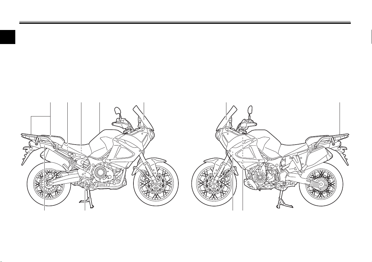
Location of important labels
1
Read and understand all of the labels on your vehicle. They contain important information for safe and proper operation of
your vehicle. Never remove any labels from your vehicle. If a label becomes difficult to read or comes off, a replacement
label is available from your Yamaha dealer.
EAU10385
1,2
3 4 76 85
11
10 912
1-1
Location of important labels
TIRE INFORMATION
Cold tire normal pressure should be set
as follows.
• Up to 90 kg (198 lbs) load
FRONT
REAR
: 225 kPa, (2.25 kgf/cm²), 33 psi
: 250 kPa, (2.50 kgf/cm²), 36 psi
• 90kg (198 lbs) ~ maximum load
FRONT
REAR
: 225 kPa, (2.25 kgf/cm²), 33 psi
: 290 kPa, (2.90 kgf/cm²), 42 psi
5PS-21668-10
INFORMATION SUR LES PNEUS
La pression des pneus à froid doit normalement
être réglée comme suit.
• Jusqu’à 90 kg (198 lb)
AVAN T
ARRIERE
: 225 kPa, (2,25 kgf/cm²), 33 psi
: 250 kPa, (2,50 kgf/cm²), 36 psi
• Entre 90 kg (198 lb) et charge maximale
AVAN T
ARRIERE
: 225 kPa, (2,25 kgf/cm²), 33 psi
: 290 kPa, (2,90 kgf/cm²), 42 psi
23P-21668-10
AVERTISSEMENT
Un chargement incorrect risque de causer
une perte de contrôle.
NE JAMAIS s’asseoir sur le porte-bagages.
Se reporter aux instructions données dans
le Manuel du propriétaire.
CHARGE LIMITE DU PORTE-BAGAGES
5 kg (11 lb)
23P-2816K-20
WARNING
Improper loading can cause loss
of control.
NEVER sit on the carrier.
Refer to instructions in the Owner’s
Manual.
CARRIER LOAD LIMIT : 5 kg (11 lbs)
23P-2816K-10
34
21
1
1-2
Location of important labels
1
WARNING
BEFORE YOU OPERATE THIS VEHICLE, READ
THE OWNER’S MANUAL AND ALL LABELS.
ALWAYS WEAR AN APPROVED MOTORCYCLE
HELMET, eye protection, and protective clothing.
AVERTISSEMENT
LIRE LE MANUEL DU PROPRIETAIRE AINSI QUE TOUTES
LES ETIQUETTES AVANT D’UTILISER CE VEHICULE.
TOUJOURS PORTER UN CASQUE DE MOTOCYCLISTE
APPROUVE, des lunettes et des vêtements de protection.
675
ATTENTION
Eviter de nettoyer le
pare-brise avec une solution
alcaline ou acide ainsi
qu’avec de l’essence ou
un diluant.
Utiliser un détergent neutre.
4B5-2815K-10
NOTICE
Cleaning with alkaline or
acid cleaner, gasoline or
solvent will damage
windshield.
Use neutral detergent.
4B5-2815K-00
PREMIUM UNLEADED GASOLINE ONLY
91 Min. Pump Octane (R+M)/2
ESSENCE SUPER SANS PLOMB EXCLUSIVEMENT
Indice d’octane à la pompe ([R+M]/2) de min. 91
29P-2816R-10
89
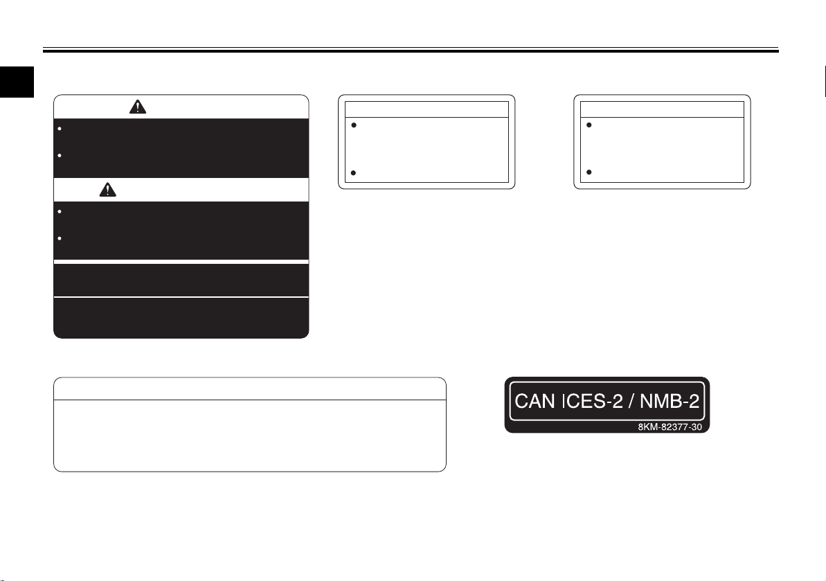
NOTICE ATTENZIONE ATTENTION ACHTUNG ATENCIÓN
• Do not lift here, carrier may be damaged.
• Non sollevare, il portapacchi potrebbe essere danneggiato.
• Ne pas soulever ici, car le porte-bagages pourrait être endommagé.
• Nicht hier anheben, Gepäckträger könnte beschädigt werden.
• No lo levante por aquí, el portaequipajes podría resultar dañado.
23P-2815T-00
1-3
•
C
M
V
S
S
•
C
A
N
A
D
A
•
N
S
V
A
C
•
T
R
A
N
S
P
O
R
T
506
23P-2816J-20
WARNING
AVERTISSEMENT
NEVER ride as a passenger
if the passenger seat
and grips are removed.
AUCUN passager ne doit rouler
quand la selle du passager et
les poignées sont déposées.
12
1110
Location of important labels
1
1-4

Safety information
Be a Responsible Owner
2
As the vehicle’s owner, you are responsible for the safe and proper operation of your motorcycle.
Motorcycles are single-track vehicles.
Their safe use and operation are dependent upon the use of proper riding
techniques as well as the expertise of
the operator. Every operator should
know the following requirements before riding this motorcycle.
He or she should:
Obtain thorough instructions from
a competent source on all aspects
of motorcycle operation.
Observe the warnings and mainte-
nance requirements in this Own-
er’s Manual.
Obtain qualified training in safe
and proper riding techniques.
Obtain professional technical ser-
vice as indicated in this Owner’s
Manual and/or when made neces-
sary by mechanical conditions.
EAU1031C
Never operate a motorcycle with-
out proper training or instruction.
Take a training course. Beginners
should receive training from a certified instructor. Contact an authorized motorcycle dealer to find out
about the training courses nearest
you.
Safe Riding
Perform the pre-operation checks
each time you use the vehicle to make
sure it is in safe operating condition.
Failure to inspect or maintain the vehicle properly increases the possibility of
an accident or equipment damage.
See page 5-1 for a list of pre-operation
checks.
This motorcycle is designed to
carry the operator and a passenger.
The failure of motorists to detect
and recognize motorcycles in traffic is the predominating cause of
automobile/motorcycle accidents.
Many accidents have been
caused by an automobile driver
who did not see the motorcycle.
Making yourself conspicuous ap-
2-1
pears to be very effective in reducing the chance of this type of
accident.
Therefore:
• Wear a brightly colored jacket.
• Use extra caution when you are
approaching and passing
through intersections, since intersections are the most likely
places for motorcycle accidents
to occur.
• Ride where other motorists can
see you. Avoid riding in another
motorist’s blind spot.
• Never maintain a motorcycle
without proper knowledge.
Contact an authorized motorcycle dealer to inform you on basic motorcycle maintenance.
Certain maintenance can only
be carried out by certified staff.

Safety information
Many accidents involve inexperi-
enced operators. In fact, many operators who have been involved in
accidents do not even have a current motorcycle license.
• Make sure that you are qualified
and that you only lend your motorcycle to other qualified operators.
• Know your skills and limits.
Staying within your limits may
help you to avoid an accident.
• We recommend that you practice riding your motorcycle
where there is no traffic until you
have become thoroughly familiar with the motorcycle and all of
its controls.
Many accidents have been
caused by error of the motorcycle
operator. A typical error made by
the operator is veering wide on a
turn due to excessive speed or undercornering (insufficient lean angle for the speed).
• Always obey the speed limit and
never travel faster than warranted by road and traffic conditions.
• Always signal before turning or
changing lanes. Make sure that
other motorists can see you.
The posture of the operator and
passenger is important for proper
control.
• The operator should keep both
hands on the handlebar and
both feet on the operator footrests during operation to maintain control of the motorcycle.
• The passenger should always
hold onto the operator, the seat
strap or grab bar, if equipped,
with both hands and keep both
feet on the passenger footrests.
Never carry a passenger unless
he or she can firmly place both
feet on the passenger footrests.
Never ride under the influence of
alcohol or other drugs.
Protective Apparel
The majority of fatalities from motorcycle accidents are the result of head injuries. The use of a safety helmet is the
single most critical factor in the prevention or reduction of head injuries.
Always wear an approved helmet.
2-2
Wear a face shield or goggles.
Wind in your unprotected eyes
could contribute to an impairment
of vision that could delay seeing a
hazard.
The use of a jacket, heavy boots,
trousers, gloves, etc., is effective
in preventing or reducing abrasions or lacerations.
Never wear loose-fitting clothes,
otherwise they could catch on the
control levers, footrests, or wheels
and cause injury or an accident.
Always wear protective clothing
that covers your legs, ankles, and
feet. The engine or exhaust system become very hot during or after operation and can cause
burns.
A passenger should also observe
the above precautions.
Avoid Carbon Monoxide Poisoning
All engine exhaust contains carbon
monoxide, a deadly gas. Breathing
carbon monoxide can cause headaches, dizziness, drowsiness, nausea,
confusion, and eventually death.
2

Safety information
Carbon Monoxide is a colorless, odorless, tasteless gas which may be present even if you do not see or smell any
2
engine exhaust. Deadly levels of carbon monoxide can collect rapidly and
you can quickly be overcome and unable to save yourself. Also, deadly levels of carbon monoxide can linger for
hours or days in enclosed or poorly
ventilated areas. If you experience any
symptoms of carbon monoxide poisoning, leave the area immediately, get
fresh air, and SEEK MEDICAL TREATMENT.
Do not run engine indoors. Even if
you try to ventilate engine exhaust
with fans or open windows and
doors, carbon monoxide can rapidly reach dangerous levels.
Do not run engine in poorly venti-
lated or partially enclosed areas
such as barns, garages, or carports.
Do not run engine outdoors where
engine exhaust can be drawn into
a building through openings such
as windows and doors.
Loading
Adding accessories or cargo to your
motorcycle can adversely affect stability and handling if the weight distribution of the motorcycle is changed. To
avoid the possibility of an accident, use
extreme caution when adding cargo or
accessories to your motorcycle. Use
extra care when riding a motorcycle
that has added cargo or accessories.
Here, along with the information about
accessories below, are some general
guidelines to follow if loading cargo to
your motorcycle:
The total weight of the operator, passenger, accessories and cargo must
not exceed the maximum load limit.
Operation of an overloaded vehicle
could cause an accident.
Maximum load:
209 kg (461 lb)
When loading within this weight limit,
keep the following in mind:
Cargo and accessory weight
should be kept as low and close to
the motorcycle as possible. Securely pack your heaviest items as
2-3
close to the center of the vehicle
as possible and make sure to distribute the weight as evenly as
possible on both sides of the motorcycle to minimize imbalance or
instability.
Shifting weights can create a sud-
den imbalance. Make sure that
accessories and cargo are securely attached to the motorcycle
before riding. Check accessory
mounts and cargo restraints frequently.
• Properly adjust the suspension
for your load (suspension-adjustable models only), and
check the condition and pressure of your tires.
• Never attach any large or heavy
items to the handlebar, front
fork, or front fender. These
items, including such cargo as
sleeping bags, duffel bags, or
tents, can create unstable handling or a slow steering response.
This vehicle is not designed to
pull a trailer or to be attached to
a sidecar.
Safety information
Genuine Yamaha Accessories
Choosing accessories for your vehicle
is an important decision. Genuine
Yamaha accessories, which are available only from a Yamaha dealer, have
been designed, tested, and approved
by Yamaha for use on your vehicle.
Many companies with no connection
to Yamaha manufacture parts and accessories or offer other modifications
for Yamaha vehicles. Yamaha is not in
a position to test the products that
these aftermarket companies produce.
Therefore, Yamaha can neither endorse nor recommend the use of accessories not sold by Yamaha or
modifications not specifically recommended by Yamaha, even if sold and
installed by a Yamaha dealer.
Aftermarket Parts, Accessories, and
Modifications
While you may find aftermarket products similar in design and quality to
genuine Yamaha accessories, recognize that some aftermarket accessories or modifications are not suitable
because of potential safety hazards to
you or others. Installing aftermarket
products or having other modifications
performed to your vehicle that change
any of the vehicle’s design or operation
characteristics can put you and others
at greater risk of serious injury or
death. You are responsible for injuries
related to changes in the vehicle.
Keep the following guidelines in mind,
as well as those provided under “Loading” when mounting accessories.
Never install accessories or carry
cargo that would impair the performance of your motorcycle.
Carefully inspect the accessory
before using it to make sure that it
does not in any way reduce
ground clearance or cornering
clearance, limit suspension travel,
steering travel or control operation, or obscure lights or reflectors.
• Accessories fitted to the handlebar or the front fork area can
create instability due to improper weight distribution or aerodynamic changes. If accessories
are added to the handlebar or
2-4
front fork area, they must be as
lightweight as possible and
should be kept to a minimum.
• Bulky or large accessories may
seriously affect the stability of
the motorcycle due to aerodynamic effects. Wind may attempt to lift the motorcycle, or
the motorcycle may become
unstable in cross winds. These
accessories may also cause instability when passing or being
passed by large vehicles.
• Certain accessories can displace the operator from his or
her normal riding position. This
improper position limits the
freedom of movement of the
operator and may limit control
ability, therefore, such accessories are not recommended.
Use caution when adding electri-
cal accessories. If electrical accessories exceed the capacity of
the motorcycle’s electrical system, an electric failure could result, which could cause a
dangerous loss of lights or engine
power.
2
Safety information
Aftermarket Tires and Rims
The tires and rims that came with your
motorcycle were designed to match
2
the performance capabilities and to
provide the best combination of handling, braking, and comfort. Other
tires, rims, sizes, and combinations
may not be appropriate. Refer to page
7-19 for tire specifications and more information on replacing your tires.
Transporting the Motorcycle
Be sure to observe following instructions before transporting the motorcycle in another vehicle.
Remove all loose items from the
motorcycle.
Check that the fuel cock (if
equipped) is in the “OFF” position
and that there are no fuel leaks.
Point the front wheel straight
ahead on the trailer or in the truck
bed, and choke it in a rail to prevent movement.
Shift the transmission in gear (for
models with a manual transmission).
Secure the motorcycle with tie-
downs or suitable straps that are
attached to solid parts of the motorcycle, such as the frame or upper front fork triple clamp (and not,
for example, to rubber-mounted
handlebars or turn signals, or
parts that could break). Choose
the location for the straps carefully
so the straps will not rub against
painted surfaces during transport.
The suspension should be com-
pressed somewhat by the tiedowns, if possible, so that the motorcycle will not bounce excessively during transport.
2-5
Left view
1 23
4
5678910
Description
EAU10411
3
1. Fuel tank cap (page 4-28)
2. Seat lock (page 4-31)
3. Carrier (page 4-38)
4. Final gear oil filler bolt (page 7-15)
5. Final gear oil drain bolt (page 7-15)
6. Coolant reservoir (page 7-17)
7. Shift pedal (page 4-24)
8. Engine oil drain bolt (oil tank) (page 7-12)
9. Engine oil drain bolt (crankcase) (page 7-12)
10.Engine oil filter cartridge (page 7-12)
3-1
Description
Right view
3
1
2 3,4 5
EAU10421
1. Rear brake fluid reservoir (page 7-24)
2. Shock absorber assembly spring preload adjusting knob (page 4-36)
3. Front fork rebound damping force adjusting screw (page 4-34)
4. Front fork spring preload adjusting bolt (page 4-34)
5. Fuses (page 7-31)
6. Front fork compression damping force adjusting screw (page 4-34)
7. Owner’s tool kit (page 7-2)
8. Battery (page 7-30)
7
9. Engine oil filler cap (page 7-12)
10.Engine oil level check window (page 7-12)
11.Brake pedal (page 4-25)
12.Shock absorber assembly rebound damping force adjusting knob
(page 4-36)
3-2
681112 910
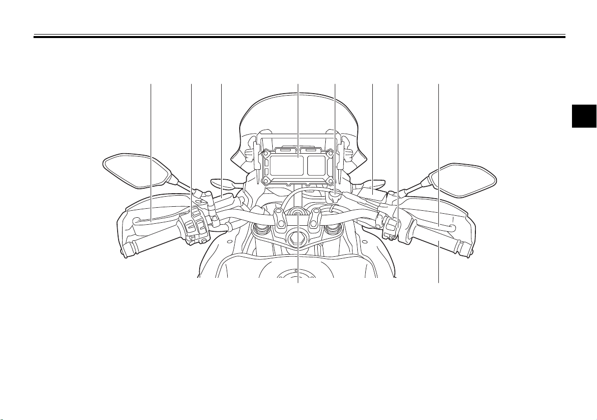
Controls and instruments
1
9
10
2 3 4 5 6 7 8
Description
EAU10431
3
1. Clutch lever (page 4-23)
2. Left handlebar switches (page 4-21)
3. Clutch fluid reservoir (page 7-24)
4. Multi-function meter unit (page 4-9)
5. Auxiliary DC jack (page 4-41)
6. Front brake fluid reservoir (page 7-24)
7. Right handlebar switches (page 4-21)
8. Brake lever (page 4-24)
9. Throttle grip (page 7-19)
10.Main switch/steering lock (page 4-2)
3-3
Instrument and control functions
NOTICE
NOTICE
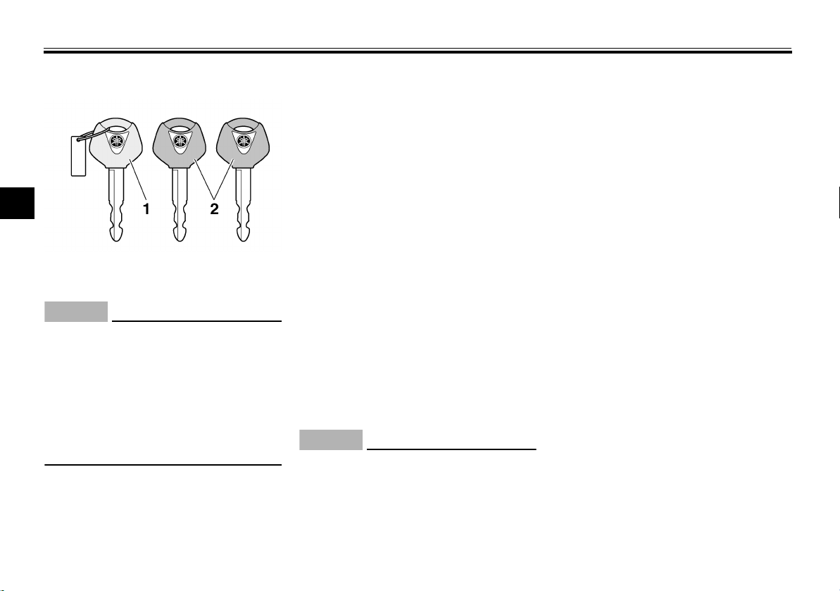
Immobilizer system
4
1. Code re-registering key (red bow)
2. Standard keys (black bow)
Operation is subject to the following
two conditions:
this device may not cause inter-
ference, and
this device must accept any in-
terference, including interference that may cause undesired
operation of the device.
This vehicle is equipped with an immobilizer system to help prevent theft by
re-registering codes in the standard
keys. This system consists of the following:
EAU36586
ECA15041
a code re-registering key (with a
red bow)
two standard keys (with a black
bow) that can be re-registered
with new codes
a transponder (which is installed in
the code re-registering key)
an immobilizer unit
an ECU
an immobilizer system indicator
light (See page 4-6.)
The key with the red bow is used to
register codes in each standard key.
Since re-registering is a difficult process, take the vehicle along with all
three keys to a Yamaha dealer to have
them re-registered. Do not use the key
with the red bow for driving. It should
only be used for re-registering the
standard keys. Always use a standard
key for driving.
ECA11822
DO NOT LOSE THE CODE RE-
REGISTERING KEY! CONTACT
YOUR DEALER IMMEDIATELY
IF IT IS LOST! If the code re-reg-
istering key is lost, registering
new codes in the standard keys
4-1
is impossible. The standard
keys can still be used to start
the vehicle, however if code reregistering is required (i.e., if a
new standard key is made or all
keys are lost) the entire immobi-
lizer system must be replaced.
Therefore, it is highly recommended to use either standard
key and keep the code re-regis-
tering key in a safe place.
Do not submerse any key in wa-
ter.
Do not expose any key to exces-
sively high temperatures.
Do not place any key close to
magnets (this includes, but not
limited to, products such as
speakers, etc.).
Do not place items that transmit
electrical signals close to any
key.
Do not place heavy items on any
key.
Do not grind any key or alter its
shape.
Do not disassemble the plastic
part of any key.
Instrument and control functions
TIP
TIP
WARNING
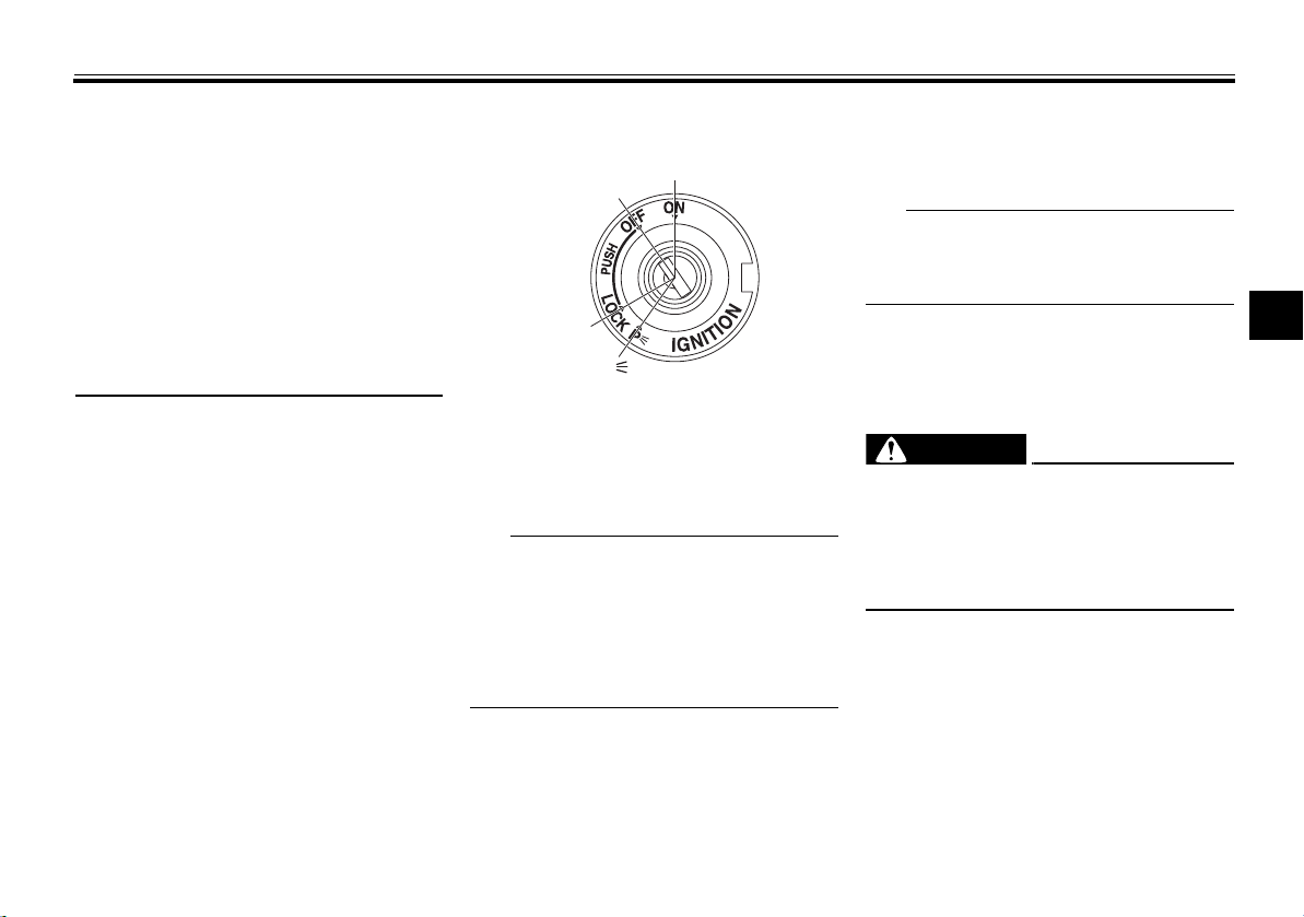
P
ON
OFF
LOCK
Do not put two keys of any im-
mobilizer system on the same
key ring.
Keep the standard keys as well
as keys of other immobilizer
systems away from this vehicle’s code re-registering key.
Keep other immobilizer system
keys away from the main switch
as they may cause signal interference.
EAU10474
Main switch/steering lock
The main switch/steering lock controls
the ignition and lighting systems, and is
used to lock the steering. The various
positions are described below.
Be sure to use the standard key (black
bow) for regular use of the vehicle. To
minimize the risk of losing the code reregistering key (red bow), keep it in a
safe place and only use it for code reregistering.
EAU51501
ON
All electrical circuits are supplied with
power; the meter lighting, taillights, license plate light, auxiliary lights and
4-2
position lights come on, and the engine
can be started. The key cannot be removed.
The headlights come on automatically
when the engine is started and stay on
until the key is turned to “OFF”.
4
EAU10662
OFF
All electrical systems are off. The key
can be removed.
EWA10062
Never turn the key to “OFF” or
“LOCK” while the vehicle is moving.
Otherwise the electrical systems will
be switched off, which may result in
loss of control or an accident.
EAU10696
LOCK
The steering is locked and all electrical
systems are off. The key can be removed.
Instrument and control functions
TIP
NOTICE
12
12
34568 7910
1 2
ABS
To lock the steering
4
1. Push.
2. Turn.
1. Turn the handlebars all the way to
the left or right.
2. With the key in the “OFF” position,
push the key in and turn it to
“LOCK”.
3. Remove the key.
If the steering will not lock, try turning
the handlebars back to the right or left
slightly.
To unlock the steering
1. Push.
2. Turn.
From the “LOCK” position, push the
key and turn it to “OFF”.
EAU59680
(Parking)
The hazard lights and turn signal lights
can be turned on, but all other electrical systems are off. The key can be removed.
The steering must be locked before the
key can be turned to “ ”.
ECA20760
EAU4939B
Indicator lights and warning lights
GEAR
N
A.TEMP ˚C
25
C.TEMP ˚C
Lo
TIME TRIP
0:00
1. Left turn signal indicator light “ ”
2. Right turn signal indicator light “ ”
3. Oil level warning light “ ”
4. Engine trouble warning light “ ”
5. Anti-lock Brake System (ABS) warning
light “ ”
6. Traction control system indicator/warning
light “TCS”
7. Cruise control indicator lights “ ”/“SET”
8. High beam indicator light “ ”
9. Neutral indicator light “ ”
10.Immobilizer system indicator light “ ”
Using the hazard or tur n signal lights
for an extended length of time may
cause the battery to discharge.
4-3
Instrument and control functions
TIP
Turn signal indicator lights “ ”
EAU11032
and “”
Each indicator light will flash when its
corresponding turn signal lights are
flashing.
EAU11061
Neutral indicator light “ ”
This indicator light comes on when the
transmission is in the neutral position.
EAU11081
High beam indicator light “ ”
This indicator light comes on when the
high beam of the headlight is switched
on.
EAU11256
Oil level warning light “ ”
This warning light comes on if the engine oil level is low.
The electrical circuit of the warning
light can be checked by turning the key
to “ON”. The warning light should
come on for a few seconds and then
go off.
If the warning light does not come on
initially when the key is turned to “ON”,
or if the warning light remains on after
confirming that the oil level is correct
(see page 7-12), have a Yamaha dealer
check the vehicle.
Even if the oil level is sufficient, the
warning light may flicker when riding on a slope or during sudden
acceleration or deceleration, but
this is not a malfunction.
This model is equipped with a self-
diagnosis device for the oil level
detection circuit. If a problem is
detected in the oil level detection
circuit, the oil level warning light
will flash repeatedly. If this occurs,
have a Yamaha dealer check the
vehicle.
EAU58401
Cruise control indicator
lights “ ”/“SET”
These indicator lights come on when
the cruise control system is activated.
See page 4-6 for a detailed explanation
of the function of these indicator lights.
The electrical circuit of these indicator
lights can be checked by turning the
key to “ON”. These indicator lights
should come on for a few seconds,
and then go off.
If an indicator light does not come on
initially when the key is turned to “ON”,
or if an indicator light remains on, have
a Yamaha dealer check the electrical
circuit.
EAU59110
Engine trouble warning light “ ”
This warning light comes on or flashes
if a problem is detected in the electrical
circuit monitoring the engine. If this occurs, have a Yamaha dealer check the
self-diagnosis system. (See page 4-20
for an explanation of the self-diagnosis
device.)
The electrical circuit of the warning
light can be checked by turning the key
to “ON”. The warning light should
come on for a few seconds, and then
go off.
4
4-4
Instrument and control functions
TIP
WARNING
TIP
ABS
132 4
If the warning light does not come on
initially when the key is turned to “ON”,
or if the warning light remains on, have
a Yamaha dealer check the electrical
circuit.
The engine trouble warning light will
come on while the start switch is
4
pushed, but this does not indicate a
malfunction.
ABS warning light “ ”
In normal operation, the ABS warning
light comes on when the key is turned
to “ON”, and goes off after traveling at
a speed of 10 km/h (6 mi/h) or higher.
If the ABS warning light:
does not come on when the key is
turned to “ON”
comes on or flashes while riding
does not go off after traveling at a
speed of 10 km/h (6 mi/h) or high-
er
The ABS may not work correctly. If any
of the above occurs, have a Yamaha
dealer check the system as soon as
possible. (See page 4-25 for an explanation of the ABS.)
EAU59120
EWA16041
If the ABS warning light does not go
off after traveling at a speed of 10
km/h (6 mi/h) or higher, or if the
warning light comes on or flashes
while riding, the brake system reverts to conventional braking. If ei-
ther of the above occurs, or if the
warning light does not come on at
all, use extra caution to avoid possi-
ble wheel lock during emergency
braking. Have a Yamaha dealer
check the brake system and electrical circuits as soon as possible.
The ABS warning light will also come
on while the start switch is pushed, but
this does not indicate a malfunction.
EAU58902
Traction control system indica-
tor/warning light “TCS”
This indicator/warning light flashes
when the traction control system engages.
4-5
The electrical circuit of the light can be
checked by turning the key to “ON”.
The light should come on for a few seconds, and then go off.
If the light does not come on initially
when the key is turned to “ON”, or if the
light remains on, have a Yamaha dealer
check the electrical circuit.
If the traction control system becomes
disabled while riding, “TCS OFF” is
displayed, and the indicator/warning
light and engine trouble warning light
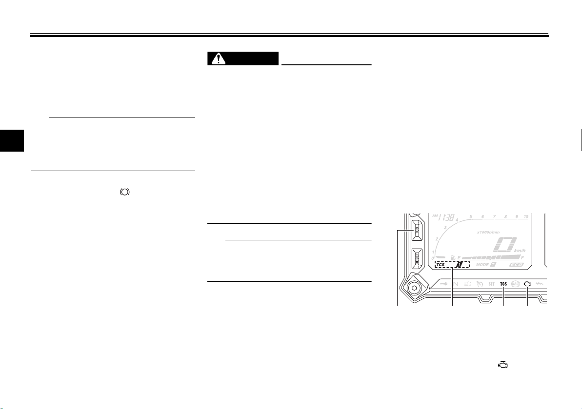
come on. (See page 4-26 for an explanation of the traction control system.)
1. “TCS” button
2. Traction control system indicator
3. Traction control system indicator/warning
light “TCS”
4. Engine trouble warning light “ ”
Instrument and control functions
WARNING
1 2
2
1
Reset the traction control system and
the lights by following the procedures
under “Resetting” on page 4-27.
Immobilizer system indicator
EAU54682
light “ ”
When the key is turned to “OFF” and
30 seconds have passed, the indicator
light will start flashing indicating the immobilizer system is enabled. After 24
hours have passed, the indicator light
will stop flashing, however the immobilizer system is still enabled.
The electrical circuit of the indicator
light can be checked by turning the key
to “ON”. The indicator light should
come on for a few seconds, and then
go off.
If the indicator light does not come on
initially when the key is turned to “ON”,
or if the indicator light remains on, have
a Yamaha dealer check the electrical
circuit.
The self-diagnosis device also detects
problems in the immobilizer system
circuits. (See page 4-20 for an explanation of the self-diagnosis device.)
EAU61120
Cruise control system
This model is equipped with a cruise
control system designed to maintain a
set cruising speed.
The cruise control system operates
only when riding in 3rd gear at speeds
between about 50 km/h (31 mi/h) and
100 km/h (62 mi/h), 4th gear at speeds
between about 50 km/h (31 mi/h) and
150 km/h (93 mi/h), or 5th or 6th gear
at speeds between about 50 km/h (31
mi/h) and 160 km/h (100 mi/h).
EWA16341
Improper use of the cruise con-
trol system may result in loss of
control, which could lead to an
accident. Do not activate the
cruise control system in heavy
traffic, poor weather conditions,
or among winding, slippery,
hilly, rough or gravel roads.
When traveling uphill or down-
hill, the cruise control system
may not be able to maintain the
set cruising speed.
To prevent accidentally activat-
ing the cruise control system,
turn it off when not in use. Make
sure that the cruise control system indicator light “ ” is off.
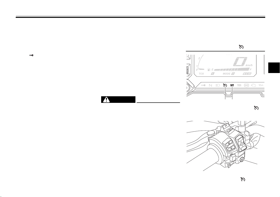
1. Cruise control system indicator light “ ”
2. Cruise control setting indicator light “SET”
S
E
R
T
E
S
PASS
1. Cruise control setting switch “RES+/SET–”
2. Cruise control power switch “ ”
4
4-6
Instrument and control functions
TIP
TIP
2
1
Activating and setting the cruise
control system
1. Push the cruise control power
switch “ ” located on the left
handlebar. The cruise control system indicator light “ ” will come
on.
2. Push the “SET–” side of the cruise
4
control setting switch to activate
the cruise control system. Your
current traveling speed will become the set cruising speed. The
cruise control setting indicator
light “SET” will come on.
Adjusting the set cruising speed
While the cruise control system is operating, push the “RES+” side of the
cruise control setting switch to increase the set cruising speed or the
“SET–” side to decrease the set speed.
Pushing the setting switch once will
change the speed in increments of approximately 2.0 km/h (1.2 mi/h). Holding the “RES+” or “SET–” side of the
cruise control setting switch down will
increase or decrease the speed continuously until the switch is released.
You can also manually increase your
traveling speed using the throttle. After
you have accelerated, you can set a
new cruising speed by pushing the
“SET–” side of the setting switch. If you
do not set a new cruising speed, when
you return the throttle grip, the vehicle
will decelerate to the previously set
cruising speed.
Deactivating the cruise control system
Perform one of the following operations to cancel the set cruising speed.
The “SET” indicator light will go off.
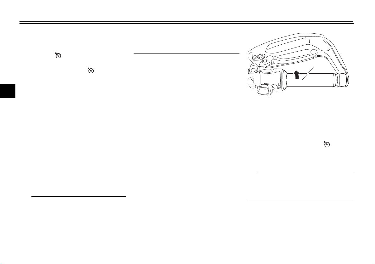
Turn the throttle grip past the
closed position in the deceleration
direction.
1. Closed position
2. Cruise control cancel direction
Apply the front or rear brake.
Disengage the clutch.
Push the power switch to turn off the
cruise control system. The “ ” indicator light and the “SET” indicator light
will go off.
Traveling speed decreases as soon as
the cruise control system is deactivated; unless the throttle grip is turned.
Using the resume function
Push the “RES+” side of the cruise
control setting switch to reactivate the
cruise control system. The traveling
4-7
Instrument and control functions
WARNING
TIP
TIP
speed will return to the previously set
cruising speed. The “SET” indicator
light will come on.
EWA16351
It is dangerous to use the resume
function when the previously set
cruising speed is too high for current
conditions.
The resume function operates
when riding in 3rd gear at speeds
between about 50 km/h (31 mi/h)
and 100 km/h (62 mi/h), 4th gear
at speeds between about 50 km/h
(31 mi/h) and 150 km/h (93 mi/h),
or 5th or 6th gear at speeds between about 50 km/h (31 mi/h)
and 160 km/h (100 mi/h).
Pushing the power switch while
the system is operating will turn
the system off completely and
erase the previously set cruising
speed. You will not be able to use
the resume function until a new
cruising speed has been set.
Automatic deactivation of the cruise
control system
The cruise control system for this model is electronically controlled and is
linked with the other control systems.
The cruise control system will automatically become deactivated under
the following conditions:
The cruise control system is not
able to maintain the set cruising
speed.
Wheel slip or wheel spin is detect-
ed. (If the traction control system
has not been turned off, the traction control system will work.)
The start/engine stop switch is set
to the “ ” position.
The engine stalls.
The sidestand is lowered.
When traveling with a set cruising
speed, if the cruise control system is
deactivated under the above conditions, the “ ” indicator light will go off
and the “SET” indicator light will flash
for 4 seconds, and then go off.
When not traveling with a set cruising
speed, if the start/engine stop switch is
set to the “ ” position, the engine
stalls, or the sidestand is lowered, then
the “ ” indicator light will go off (the
“SET” indicator light will not flash).
If the cruise control system is automatically deactivated, please stop and
confirm that your vehicle is in good operating condition.
Before using the cruise control system
again, activate it using the power
switch.
In some cases, the cruise control system may not be able to maintain the set
cruising speed when the vehicle is
traveling uphill or downhill.
When the vehicle is traveling up-
hill, the actual traveling speed may
become lower than the set cruising speed. If this occurs, accelerate to the desired traveling speed
using the throttle.
When the vehicle is traveling
downhill, the actual traveling
speed may become higher than
the set cruising speed. If this occurs, the setting switch cannot be
used to adjust the set cruising
speed. To reduce the traveling
4
4-8
Instrument and control functions
WARNING
NOTICE
WARNING
1 2 3 4
89101112
12 3 4 56
7
speed, apply the brakes. When
the brakes are applied, the cruise
control system will become deactivated.
Self-diagnosis device
4
1. Cruise control system indicator light “ ”
2. Cruise control setting indicator light “SET”
3. Engine trouble warning light “ ”
4. Error code display
The cruise control system will also become deactivated when an irregularity
with any of the vehicle systems is detected. The “SET” indicator light will go
off and the “ ” indicator light will
flash. You will not be able to use the
cruise control system while the engine
GEAR
N
A.TEMP ˚C
C.TEMP ˚C
TIME TRIP
25
Lo
0:00
trouble warning light is on, or while the
cruise control system is malfunctioning.
EWA16361
If the cruise control system is not
working correctly, the “ ” indicator
light will flash. If this occurs, turn the
cruise control system off and have a
Yamaha dealer check it.
ECA11591
If the display indicates an error co-
de, the vehicle should be checked as
soon as possible in order to avoid
engine damage.
EAU59099
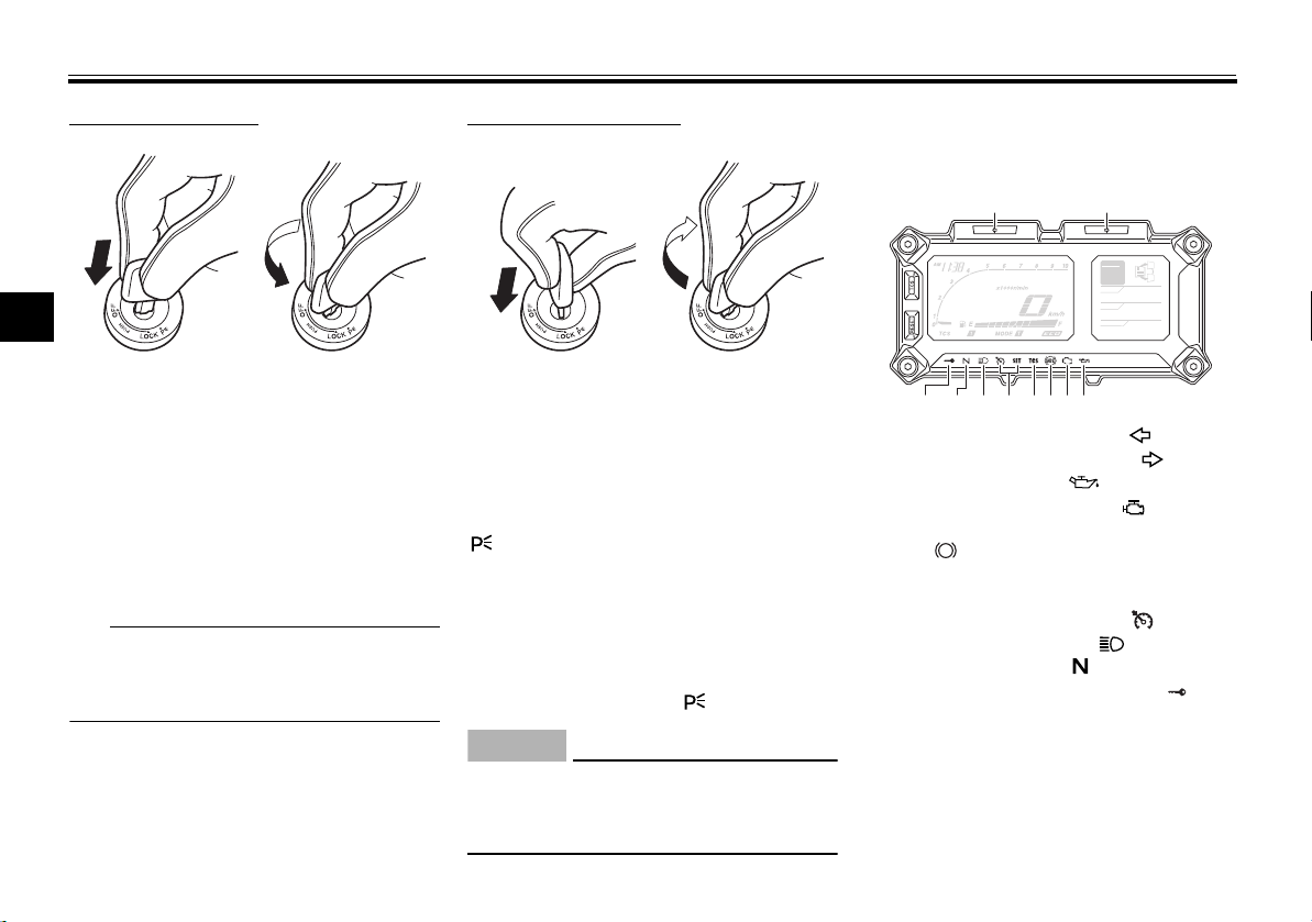
Multi-function meter unit
GEAR
N
A.TEMP ˚C
25
C.TEMP ˚C
Lo
TIME TRIP
0:00
1. “RESET” button
2. “TCS” button
3. Clock
4. Tachometer
5. Speedometer
6. Transmission gear indicator
7. Information display selection function
8. Information display
9. Fuel meter
10.Eco indicator “ECO”
11.Drive mode indicator
12.Traction control system indicator
EWA12423
Be sure to stop the vehicle before
making any setting changes to the
multi-function meter unit. Changing
4-9
Instrument and control functions
TIP
TIP
NOTICE
1
2
12
settings while riding can distract the
operator and increase the risk of an
accident.
The multi-function meter unit is
equipped with:
speedometer
tachometer
clock
fuel meter
eco indicator
transmission gear indicator
drive mode indicator
traction control system indicator
information display
setting mode
self-diagnosis device
The select switch “ / ” and the
menu switch “MENU” are located on
the left handlebar. These switches allow you to control or change the settings of the multi-function meter unit.
1. Menu switch “MENU”
2. Select switch “ / ”
Be sure to turn the key to “ON” before
pushing the select switch “ / ”,
menu switch “MENU”, “RESET” button and “TCS” button.
Speedometer
The speedometer shows the vehicle’s
traveling speed.
To switch between kilometers and
miles, see “Selecting the units” on
page 4-17.
Tachometer
4
1. Tachometer
2. High-rpm zone
The tachometer shows the engine
speed.
ECAM1150
Do not operate the engine in the tachometer high-rpm zone.
High-rpm zone: 7750 r/min and
above
4-10
Instrument and control functions
TIP
TIP
1
1
1 2
Fuel meter
4
1. Fuel meter
The fuel meter indicates the amount of
fuel in the fuel tank. The display segments of the fuel meter disappear from
“F” (full) towards “E” (empty) as the fuel
level decreases. When the last segment starts flashing, refuel as soon as
possible.
If a problem is detected in the fuel meter circuit, all display segments of the
fuel meter will start flashing. If this occurs, have a Yamaha dealer check the
vehicle.
Eco indicator
1. Eco indicator “ECO”
This indicator comes on when the vehicle is being operated in an environmentally friendly, fuel-efficient manner.
The indicator goes off when the vehicle
is stopped.
Consider the following tips to reduce
fuel consumption:
Avoid high engine speeds during
acceleration.
Travel at a constant speed.
Select the transmission gear that
is appropriate for the vehicle
speed.
Transmission gear indicator
GEAR
N
A.TEMP ˚C
C.TEMP ˚C
TIME TRIP
1. Neutral indicator light “ ”
2. Transmission gear indicator
25
Lo
0:00
This indicator shows the current transmission gear and neutral position as
follows: 1–N–2–3–4–5–6. When the
clutch lever is pulled or the vehicle is
stopped, “—” will be displayed.
4-11
 Loading...