


SERVICE MANUAL
2008
11D-F8197-E0
XT660Z

XT660Z (2008)
SERVICE MANUAL
© 2008 by Yamaha Motor Italia S.p.A.
First edition, May 2008
All rights reserved. Any reproduction or
unauthorized use without the written
permission of Yamaha Motor Italia S.p.A.
is expressly prohibited.
Printed in Italy

EAS00020
NOTICE
This manual was produced by the Yamaha Motor Italia S.p.A. primarily for use by Yamaha dealers and
their qualified mechanics. It is not possible to include all the knowledge of a mechanic in one manual. Therefore, anyone who uses this book to perform maintenance and repairs on Yamaha vehicles
should have a basic understanding of mechanics and the techniques to repair these types of vehicles. Repair and maintenance work attempted by anyone without this knowledge is likely to render
the vehicle unsafe and unfit for use.
Yamaha Motor Italia S.p.A. is continually striving to improve all of its models. Modifications and significant changes in specifications or procedures will be forwarded to all authorized Yamaha dealers
and will appear in future editions of this manual where applicable.
NOTE:
Designs and specifications are subject to change without notice.
EAS00040
IMPORTANT MANUAL INFORMATION
Particularly important information is distinguished in this manual by the following.
The Safety Alert Symbol means ATTENTION! BECOME ALERT! YOUR SAFETY IS INVOLVED!
Failure to follow WARNING instructions could result in se
vere injury or death to
the motorcycle operator, a bystander or a person checking or repairing the motorcycle.
A CAUTION indicates special precautions that must be taken to avoid damage
to the motorcycle.
NOTE: A NOTE provides key information to make procedures easier or clearer.
WARNING
CAUTION:

EAS20090
HOW TO USE THIS MANUAL
This manual is intended as a handy, easy-to-read reference book for the mechanic. Comprehensive
explanations of all installation, removal, disassembly, assembly, repair and check procedures are
laid out with the individual steps in sequential order.
• The manual is divided into chapters and each chapter is divided into sections. The current section
title “1” is shown at the top of each page.
• Sub-section titles “2” appear in smaller print than the section title.
• To help identify parts and clarify procedure steps, there are exploded diagrams “3” at the start of
each removal and disassembly section.
• Numbers “4” are given in the order of the jobs in the exploded diagram. A number indicates a disassembly step.
• Symbols “5” indicate parts to be lubricated or replaced. Refer to “SYMBOLS”.
• A job instruction chart “6” accompanies the exploded diagram, providing the order of jobs, names
of parts, notes in jobs, etc.
• Jobs “7” requiring more information (such as special tools and technical data) are described
sequentially.

EAS20100
SYMBOLS
The following symbols are used in this manual
for easier understanding.
NOTE:
The following symbols are not relevant to every
vehicle.
1. Serviceable with engine mounted
2. Filling fluid
3. Lubricant
4. Special tool
5. Tightening torque
6. Wear limit, clearance
7. Engine speed
8. Electrical data
9. Engine oil
10. Gear oil
11. Molybdenum disulfide oil
12. Wheel bearing grease
13. Lithium-soap-based grease
14. Molybdenum disulfide grease
15. Apply locking agent (LOCTITE®)
16. Replace the part with a new one.
New
12 3
45
78
6
91110
12 1413
15 16

GENERAL INFORMATION
TABLE OF CONTENTS
1
SPECIFICATIONS
2
PERIODIC CHECKS AND
ADJUSTMENTS
3
CHASSIS
4
ENGINE
5
COOLING SYSTEM
6
FUEL INJECTION SYSTEM
7
ELECTRICAL SYSTEM
8
TROUBLESHOOTING
9

GENERAL INFORMATION
IDENTIFICATION............................................................................................ 1-1
VEHICLE IDENTIFICATION NUMBER..................................................... 1-1
MODEL LABEL......................................................................................... 1-1
FEATURES ..................................................................................................... 1-2
OUTLINE OF THE FI SYSTEM................................................................ 1-2
FI SYSTEM............................................................................................... 1-3
INSTRUMENT FUNCTIONS .................................................................... 1-4
IMPORTANT INFORMATION ........................................................................ 1-7
PREPARATION FOR REMOVAL AND DISASSEMBLY ........................... 1-7
REPLACEMENT PARTS .......................................................................... 1-7
GASKETS, OIL SEALS AND O-RINGS ................................................... 1-7
LOCK WASHERS/PLATES AND COTTER PINS..................................... 1-7
BEARINGS AND OIL SEALS ................................................................... 1-8
CIRCLIPS ................................................................................................. 1-8
CHECKING THE CONNECTIONS ................................................................ 1-9
SPECIAL TOOLS ...........................................................................................1-10
1


1-1
IDENTIFICATION
1
1
IDENTIFICATION
EAS00170
VEHICLE IDENTIFICATION NUMBER
The vehicle identification number “1” is stamped
into the right side of the steering head pipe.
EAS00180
MODEL LABEL
The model label “1” is affixed to the frame under
the seat. This information will be needed to order spare parts.

1-2
FEATURES
EAS00019
FEATURES
EAS00896
OUTLINE OF THE FI SYSTEM
The main function of a fuel supply system is to provide fuel to the combustion chamber at the optimum air-fuel ratio in accordance with the engine operating conditions and the atmospheric temperature. In a conventional carburetor system, the air-fuel ratio of the mixture that is supplied to the combustion chamber is created by the volume of the intake air and the fuel that is metered by the jet used
in the respective chamber. Despite the same volume of intake air, the fuel volume requirement varies
with the engine operating conditions, such as acceleration, deceleration, or operation under a heavy
load. Carburetors that meter the fuel through the use of jets have been provided with various auxiliary devices, so that an optimum air-fuel ratio can be achieved to accommodate the constant changes
in the operating conditions of the engine. As the requirements for engines to deliver more performance and cleaner exhaust gases increase, it becomes necessary to control the air-fuel ratio in a more
precise and finely tuned manner. To accommodate this need, this model has adopted an electronically controlled fuel injection (FI) system in place of a conventional carburetor system. This system
can achieve an optimum air-fuel ratio required by the engine at all times by using a microprocessor
that regulates the fuel injection volume according to the engine operating conditions detected by various sensors. Adoption of the FI system has resulted in a highly precise fuel supply, improved engine
response, better fuel economy, and reduced exhaust emissions. Furthermore, the air induction system (AI system) has been placed under computer control together with the FI system in order to realize cleaner exhaust gases.
1. Fuel tank
2. Engine trouble warning light
3. Ignition coil
4. Spark plug
5. Fuel pump
6. Idling adjustment screw
7. Throttle position sensor
8. Intake air pressure sensor
9. Air filter case
10. ECU
11. Lean angle cut-off switch
12. Catalytic converter
13. Fuel injection system relay
14. Battery
15. Intake air temperature sensor
16. Coolant temperature sensor
17. Fuel injector
18. Crankshaft position sensor
19. O2 sensor
20. Air induction system solenoid
21. Air cut-off valve

1-3
FEATURES
EAS00897
FI SYSTEM
The fuel pump delivers fuel to the injector via the fuel filter. The pressure regulator maintains the fuel pressure that is applied to the injector at 324 kPa (3.24 kg/cm
2
, 46.1 psi) higher than the intake
manifold pressure. Accordingly, when the energizing signal from the ECU energizes the injector, the
fuel passage opens, causing the fuel to be injected into the intake manifold only during the time the
passage remains open. Therefore, the longer the length of time the injector is energized (injection duration), the greater the volume of fuel that is supplied. Conversely, the shorter the length of time the
injector is energized (injection duration), the lesser the volume of fuel that is supplied.
The injection duration and the injection timing are controlled by the ECU. Signals that are input from
the throttle position sensor, crankshaft position sensor, intake air pressure sensor, intake air temperature sensor, coolant temperature sensor and O
2
sensor enable the ECU to determine the injection
duration. The injection timing is determined through the signal from the crankshaft position sensor.
As a result, the volume of fuel that is required by the engine can be supplied at all times in accordance with the driving conditions.
Illustration is for reference only.
1. Fuel pump
2. Pressure regulator
3. Fuel injector
4. Throttle body
5. Intake air temperature sensor
6. Throttle position sensor
7. Intake air pressure sensor
8. ECU
9. Coolant temperature sensor
10. Crankshaft position sensor
11. O
2
sensor
12. Catalytic converter
A. Fuel system
B. Air system
C. Control system
2
1
5
4
8
7
6
9
#
3
1
A
B
C
10
12
11

1-4
FEATURES
INSTRUMENT FUNCTIONS
EAUB1500
Multi-function display
1. Tachometer
2. Speedometer
3. Odometer
4. Tripmeters/Fuel reserve tripmeter
5. Clock
6. Fuel meter
7. “RESET” button
8. “SELECT” button
EWA12311
WARNING
Be sure to stop the vehicle before making
any setting changes to the multi-function
display.
The multi-function display is equipped with the
following:
• a speedometer (which shows the riding
speed)
• a digital tachometer (which shows engine
r/min)
• an odometer (which shows the total distance
traveled)
• two tripmeters (which show the distance
traveled since they were last set to zero)
• a fuel reserve tripmeter (which shows the
distance traveled since the bottom segment
of the fuel meter started flashing)
• a clock
• a fuel meter
• a self-diagnosis device
NOTE:
• Be sure to turn the key to "ON" before using
the "SELECT" and "RESET" buttons.
• For the U.K. only: To switch the speedometer
and odometer/tripmeter displays between
kilometers and miles, push the "SELECT"
and "RESET" buttons together and turn the
key to "ON". When the digits start flashing on
the display push the "SELECT" button to
choose kilometers or miles.
Tachometer
1. Tachometer
2. Red zone
The tachometer allows the rider to monitor the
engine speed and keep it within the ideal power range.
When the key is turned to "ON", the tachometer
needle will sweep once across the r/min range
and then return to zero r/min in order to test the
electrical circuit.
ECA10030
CAUTION:
Do not operate the engine in the tachometer red zone.
Red zone: 7,500 r/min and above.

1-5
FEATURES
Tripmeter and tachometer modes
1. “SELECT” button
2. “RESET” button
Pushing the "SELECT" button switches the display between the tripmeter modes "TRIP 1" and
"TRIP 2" in the following order:
TRIP 1
6 TRIP 2 6 TRIP 1
When the fuel amount in the fuel tank decreases to 6.7 L (1.77 US gal) (1.47 Imp.gal), the bottom segment of the fuel meter will start flashing,
and the tripmeter display will automatically
change to the fuel reserve tripmeter mode “FTRIP” and start counting the distance traveled
from that point. In that case, pushing the "SELECT" button switches the display between the
various tripmeter modes in the following order:
F-TRIP
6 TRIP 1 6 TRIP 2 6 F-TRIP
To reset a tripmeter, select it by pushing the "SELECT" button, and then push the "RESET" button
for at least four seconds. If you do not reset the fuel reserve tripmeter manually, it will reset itself automatically and the display will return to the prior
mode after refueling and traveling 5 km (3 mi).
Clock mode
1. Clock
2. “SELECT” button
3. “RESET” button
NOTE:
The clock is displayed even when the key is
turned to "OFF".
T
o set the clock
1. Push the "SELECT" button for at least four
seconds.
2. When the hour digits start flashing, push the
"RESET" button to set the hours.
3. Push the "SELECT" button, and the minute
digits will start flashing.
4. Push the "RESET" button to set the minutes.
5. Push the "SELECT" button and then release
it to start the clock.
Fuel meter
1. Fuel meter
With the key in the "ON" position, the fuel meter
indicates the amount of fuel in the fuel tank.
When the key is turned to "ON", all of the display
segments of the fuel meter will appear one after
the other and then disappear in order to test the
electrical circuit. The display segments of the fuel meter disappear towards "E" (Empty) as the
fuel level decreases. When only one segment is
left near "E" (Empty), refuel as soon as possible.

1-6
FEATURES
NOTE:
This fuel meter is equipped with a selfdiagnosis
system. If the electrical circuit is defective all
the segments will start flashing.
Self-diagnosis devices
1. Engine trouble warning light “U”
2. Immobilizer system indicator light “ ”
This model is equipped with a self-diagnosis
device for various electrical circuits.
If any of those circuits are defective, the engine
trouble warning light will start flashing.
Refer to “FUEL INJECTION SYSTEM” on page
7-16. This model is also equipped with a self-diagnosis device for the immobilizer system.
Turn the key to "ON". If any of the immobilizer
system circuits are defective, the immobilizer
system indicator light will flash, and it will indicate an error code. Refer to “IMMOBILIZER
SYSTEM” on page 8-29. However, if the indicator light slowly flashes five times, and then
quickly flashes two times repeatedly, this error
could be caused by signal interference. If this
occurs, try the following.
1. Use the code re-registering key to start the
engine.
NOTE:
Make sure there are no other immobilizer keys
close to the main switch, and do not keep more
than one immobilizer key on the same key ring!
Immobilizer system keys may cause signal interference, which may prevent the engine from
starting.
2. If the engine starts, turn it off and try starting
the engine with the standard keys.
3. If one or both of the standard keys do not start
the engine, re-register the standard keys.
If the multifunction display indicates an error
code, note the code number, and then check
the vehicle. Refer to “IMMOBILIZER SYSTEM”
on page 8-29.
ECA11590
CAUTION:
If the display indicates an error code, the
vehicle should be checked as soon as possible in order to avoid engine damage.

1-7
IMPORTANT INFORMATION
EAS20180
IMPORTANT INFORMATION
EAS20190
PREPARATION FOR REMOVAL AND
DISASSEMBLY
1. Before removal and disassembly, remove all
dirt, mud, dust and foreign material.
2. Use only the proper tools and cleaning
equipment.
Refer to “SPECIAL TOOLS” on page 1-10.
3. When disassembling, always keep mated
parts together. This includes gears, cylinders,pistons and other parts that have been
“mated” through normal wear. Mated parts
must always be reused or replaced as an
assembly.
4. During disassembly, clean all of the parts
and place them in trays in the order of disassembly. This will speed up assembly and
allow for the correct installation of all parts.
5. Keep all parts away from any source of fire.
EAS20200
REPLACEMENT PARTS
Use only genuine Yamaha parts for all replacements. Use oil and grease recommended by
Yamaha for all lubrication jobs. Other brands
may be similar in function and appearance, but
inferior in quality.
EAS20210
GASKETS, OIL SEALS AND O-RINGS
1. When overhauling the engine, replace all
gaskets, seals and O-rings. All gasket surfaces, oil seal lips and O-rings must be
cleaned.
2. During reassembly, properly oil all mating
parts and bearings and lubricate the oil seal
lips with grease.
1. Oil
2. Lip
3. Spring
4. Grease
EAS20220
LOCK WASHERS/PLATES AND COTTER
PINS
After removal, replace all lock washers/plates
“1” and cotter pins. After the bolt or nut has
been tightened to specification, bend the lock
tabs along a flat of the bolt or nut.

1-8
IMPORTANT INFORMATION
EAS20230
BEARINGS AND OIL SEALS
Install bearings “1” and oil seals “2” so that the
manufacturer’s marks or numbers are visible.
When installing oil seals, lubricate the oil seal
lips with a light coat of lithium-soap-based
grease. Oil bearings liberally when installing, if
appropriate.
ECA13300
CAUTION:
Do not spin the bearing with compressed
air because this will damage the bearing
surfaces.
EAS20240
CIRCLIPS
Before reassembly, check all circlips carefully
and replace damaged or distorted circlips. Always replace piston pin clips after one use.
When installing a circlip “1”, make sure the
sharp-edged corner “2” is positioned opposite
the thrust “3” that the circlip receives.

1-9
CHECKING THE CONNECTIONS
EAS20250
CHECKING THE CONNECTIONS
Check the leads, couplers, and connectors for
stains, rust, moisture, etc.
1. Disconnect:
• Lead
• Coupler
• Connector
2. Check:
• Lead
• Coupler
• Connector
Moisture → Dry with an air blower.
Rust/stains → Connect and disconnect several
times.
3. Check:
• All connections
Loose connection → Connect properly.
NOTE:
If the pin “1” on the terminal is flattened, bend
it up.
4. Connect:
• Lead
• Coupler
• Connector
NOTE:
Make sure all connections are tight.
5. Check:
• Continuity
(with the pocket tester)
Pocket tester
90890-03112
NOTE:
• If there is no continuity, clean the terminals.
• When checking the wire harness, perform
steps (1) to (3).
• As a quick remedy, use a contact revitalizer
available at most part stores.
1-10
SPECIAL TOOLS
EAS00027
SPECIAL TOOLS
The following special tools are necessary for complete and accurate tune-up and assembly. Use only the
appropriate special tools as this will help prevent damage caused by the use of inappropriate tools or improvised techniques. Special tools, part numbers or both may differ depending on the country.
When placing an order, refer to the list provided below to avoid any mistakes.
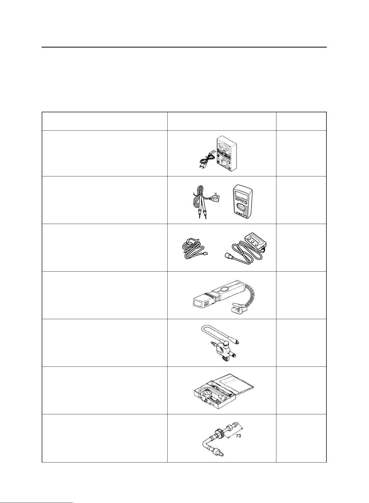
Tool name/Tool No. Illustration
Reference
pages
Pocket tester
90890-03112
Digital circuit tester
90890-03174
Fuel injection system tester
90890-03182
Timing light
90890-03141
Ignition checker
90890-06754
Compression gauge
90890-03081
Adaptor (Compression gauge)
90890-04082
5-58, 8-45, 8-46,
8-47, 8-48, 8-52,
8-53, 8-54, 8-55,
8-56, 8-57, 8-58,
8-59, 8-60
7-10
7-23
3-7
8-55
3-8
3-8
1-11
SPECIAL TOOLS
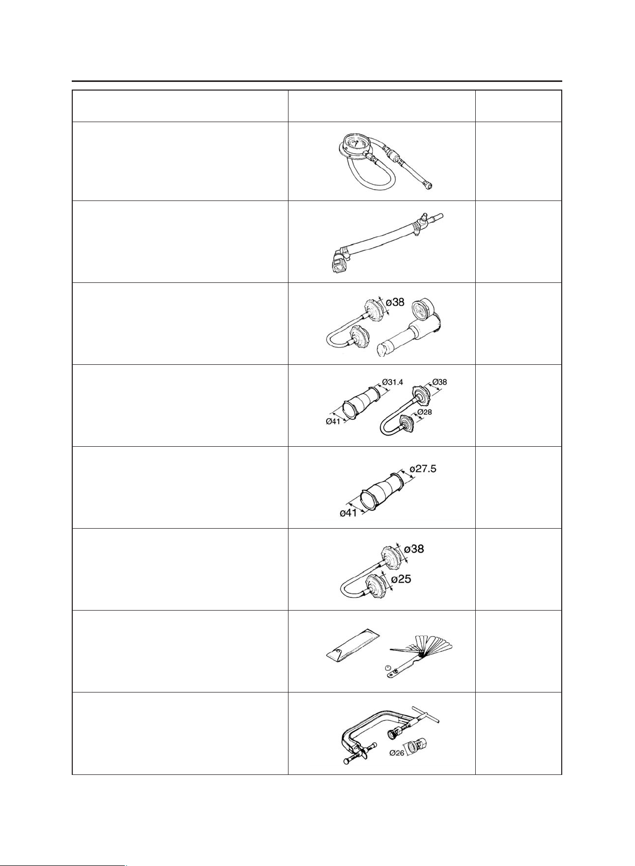
Tool name/Tool No. Illustration
Reference
pages
Pressure gauge
90890-03153
Fuel pressure adapter
90890-03176
Radiator cap tester
90890-01325
Radiator cap tester adaptor
90890-01352
Radiator cap tester adapter
90890-01497
Radiator tester adapter
90890-01496
Thickness gauge
90890-03079
Valve spring compressor attachment
90890-01243
Valve spring compressor
90890-04019
7-8
7-8
6-2, 6-3
6-2
6-2
6-3
6-2
6-3
3-4
5-20, 5-25

1-12
SPECIAL TOOLS
Tool name/Tool No. Illustration
Reference
pages
Slide hammer bolt
90890-01083
Weight
90890-01084
Piston pin puller set
90890-01304
Valve guide remover (ø 6)
90890-04064
Valve guide installer (ø 6)
90890-04065
Valve guide reamer (ø 6)
90890-04066
Valve lapper
90890-04101
Flywheel puller
90890-01362
Sheave holder
90890-01701
5-15, 5-17
5-27
5-21
5-21
5-21
-
5-53
5-53, 5-55

1-13
SPECIAL TOOLS
Tool name/Tool No. Illustration
Reference
pages
Universal clutch holder
90890-04086
Crankcase separating tool
90890-01135
Crankshaft installer pot
90890-01274
Crankshaft installer bolt
90890-01275
Adapter
90890-04130
Spacer (crankshaft installer)
90890-04144
Middle driven shaft bearing driver
90890-04058
Mechanical seal installer
90890-04132
Steering nut wrench
90890-01403
Ring nut wrench
90890-01268
T-handle
90890-01326
Damper rod holder
90890-01460
5-35, 5-37
5-67
5-68
5-68
6-10
3-24, 4-59,
4-60
4-59
4-51, 4-53

1-14
SPECIAL TOOLS
Tool name/Tool No. Illustration
Reference
pages
Fork seal driver weight
90890-01367
Fork seal driver attachment (ø 43)
90890-01374
Yamaha bond No. 1215
90890-85505
4-53, 4-54
5-55, 5-62,
5-64, 6-10

SPECIFICATIONS
GENERAL SPECIFICATIONS........................................................................ 2-1
ENGINE SPECIFICATIONS .......................................................................... 2-2
CHASSIS SPECIFICATIONS ......................................................................... 2-10
ELECTRICAL SPECIFICATIONS ..................................................................2-13
TIGHTENING TORQUES ...............................................................................2-16
GENERAL TIGHTENING TORQUE SPECIFICATIONS ..........................2-16
ENGINE TIGHTENING TORQUES ..........................................................2-17
CHASSIS TIGHTENING TORQUES ........................................................2-21
LUBRICATION POINTS AND LUBRICANT TYPES .....................................2-25
ENGINE....................................................................................................2-25
CHASSIS..................................................................................................2-27
COOLING SYSTEM DIAGRAMS...................................................................2-28
LUBRICATION CHART..................................................................................2-32
LUBRICATION DIAGRAMS......................................................................2-33
CABLE ROUTING .........................................................................................2-41
2


2-1
GENERAL SPECIFICATIONS
GENERAL SPECIFICATIONS
Model
Model code 11D1 (EUR)
Dimensions
Overall length 2246 mm (88.42 in)
Overall width 864 mm (34.01 in)
Overall height 1477 mm (58.14 in)
Seat height 896 mm (35.27 in)
Wheelbase 1500 mm (59.05 in)
Ground clearance 260 mm (10.23 in)
Minimum turning radius 1958 mm (77.08 in)
Weight
With oil and fuel 208.5 kg (459 lb)
Maximum load 190 kg (419 lb)

2-2
ENGINE SPECIFICATIONS
ENGINE SPECIFICATIONS
Engine
Engine type Liquid-cooled, 4-stroke, SOHC
Displacement 660 cm
3
(40.27 cu·in)
Cylinder arrangement Forward-inclined single cylinder
Bore x stroke 100.0 x 84.0 mm (3.94 x 3.31 in)
Compression ratio 10.00 : 1
Engine idling speed 1,400-1,600 r/min
Water temperature 80 °C (176 °F)
Oil temperature 55-65 °C (131-152 °F)
Standard compression pressure 650 kPa/800 r/min (6.5 kg/cm
2
/800 r/min,
92.4 psi/800 r/min)
Starting system Electric starter
Fuel
Recommended fuel Premium unleaded gasoline only
Fuel tank capacity 23.0 L (5.06 Imp gal, 6.07 US gal)
Fuel reserve amount 6.7 L (1.46 Imp gal, 1.76 US gal)
Engine oil
Lubrication system Dry sump
Oil type SAE10W30 or SAE10W40 or SAE15W40
or SAE20W40 or SAE20W50
Recommended engine oil grade API service SG type or higher,
JASO standard MA
Engine oil quantity
Total amount 2.90 L (2.55 Imp qt, 3.07 US qt)
Without oil filter element replacement 2.50 L (2.19 Imp qt, 2.64 US qt)
With oil filter element replacement 2.60 L (2.26 Imp qt, 2.73 US qt)
Oil filter
Oil filter type Paper
Air filter
Air filter element Dry element
Oil pump
Oil pump type Trochoid
Inner-rotor-to-outer-rotor-tip clearance 0.025 mm (0.00098 in)
Limit 0.20 mm (0.00079 in)
Outer-rotor-to-oil-pump-housing clearance 0.090-0.150 mm (0.0035-0.0059 in)
Limit 0.22 mm (0.0087 in)
Oil pump housing-to-inner-rotor and outer-rotor
clearance 0.03-0.08 mm (0.0012-0.0031 in)
Limit 0.15 mm (0.0059 in)
Bypass valve opening pressure 40.0-80.0 kPa (5.8-11.6 psi)
(0.40-0.80 kg/cm
2
)
Pressure check location Oil filter chamber

2-3
ENGINE SPECIFICATIONS
Cooling system
Radiator capacity (including all routes) 1.20 L (1.25 US qt) (1.06 Imp.qt)
Coolant reservoir capacity 0.50 L (0.52 US qt) (0.44 Imp.qt)
(up to the maximum level mark)
Radiator cap opening pressure 110.0-140.0 kPa (16.0-20.3 psi)
(1.10-1.40 kg/cm
2
)
Radiator core
Width 332.0 mm (13.07 in)
Height 158.0 mm (6.22 in)
Depth 23.0 mm (0.91 in)
Water pump
Water pump type Single suction centrifugal pump
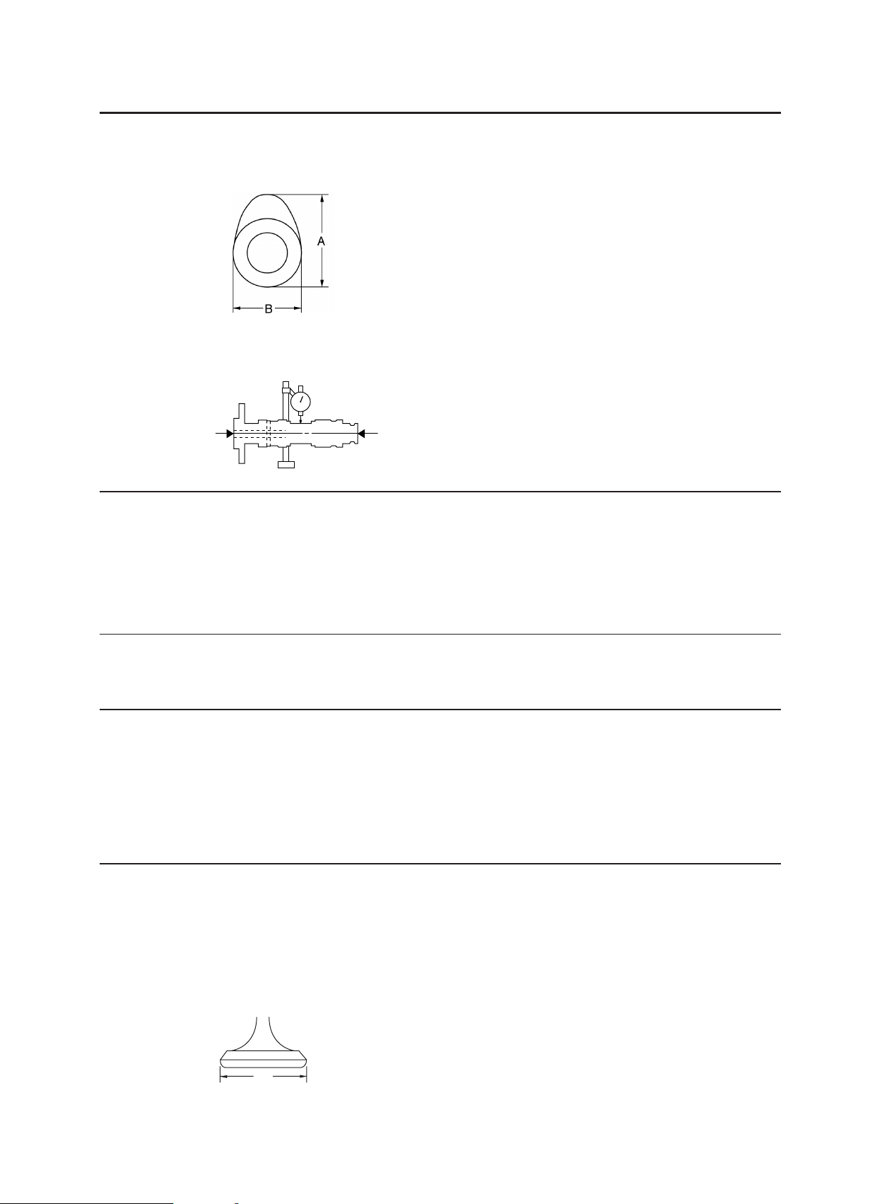
Reduction ratio 27/28 (0.964)
Maximum impeller shaft tilt 0.15 mm (0.006 in)
Spark plug
Manufacturer/Model NGK/CR7E
Spark plug gap 0.7-0.8 mm (0.028-0.031 in)
Cylinder head
Volume 59.10-60.50 cm
3
(3.61-3.69 cu·in)
Maximum warpage* 0.03 mm (0.0012 in)
Camshaft
Drive system Chain drive (left)
Camshaft lobe dimensions
Intake A 43.488-43.588 mm (1.7121-1.7161 in)
Limit 43.338 mm (1.7062 in)
Intake B 36.959-37.059 mm (1.4551-1.4590 in)
Limit 36.859 mm (1.4511 in)
Intake (depth) 6.538 mm (0.2574 in)
Exhaust A 43.129-43.229 mm (1.6980-1.7019 in)
Limit 43.029 mm (1.694 in)
2-4
ENGINE SPECIFICATIONS
Exhaust B 37.007-37.107 mm (1.4570-1.4609 in)
Limit 36.907 mm (1.4530 in)
Exhaust (depth) 6.179 mm (0.2432 in)
Camshaft runout limit 0.030 mm (0.0012 in)
Valve timing
Intake - open (B.T.D.C.) 25°
Intake - closed (A.B.D.C.) 55°
Exhaust - open (B.B.D.C.) 60°
Exhaust - closed (A.T.D.C.) 20°
Overlap angle “A” 45°
Timing chain
Model/number of links 98 x RH2010/126
Tensioning system Automatic
Rocker arm/rocker arm shaft
Rocker arm inside diameter 12.000-12.018 mm (0.4724-0.4731 in)
Limit 12.036 mm (0.4739 in)
Rocker arm shaft outside diameter 11.981-11.991 mm (0.4717-0.4721 in)
Limit 11.955 mm (0.4707 in)
Rocker-arm-to-rocker-arm-shaft clearance 0.009-0.037 mm (0.0004-0.0015 in)
Limit 0.081 mm (0.0032 in)
Valves, valve seats, valve guides
Valve clearance (cold)
Intake 0.09-0.13 mm (0.0035-0.0051 in)
Exhaust 0.16-0.20 mm (0.0063-0.0079 in)
Valve dimensions
Valve head diameter A (intake) 37.90-38.10 mm (1.4921-1.5000 in)
Valve head diameter A (exhaust) 31.90-32.10 mm (1.2559-1.2638 in)
A

2-5
ENGINE SPECIFICATIONS
Valve face width B (intake) 1.910-2.620 mm (0.075-0.103 in)
Valve face width B (exhaust) 1.910-2.620 mm (0.075-0.103 in)
Valve seat width C (intake) 1.00-1.20 mm (0.0394-0.0472 in)
Limit 1.6 mm (0.06 in)
Valve seat width C (exhaust) 1.00-1.20 mm (0.0394-0.0472 in)
Limit 1.6 mm (0.06 in)
Valve margin thickness D (intake) 0.80-1.20 mm (0.0315-0.0472 in)
Valve margin thickness D (exhaust) 0.80-1.20 mm (0.0315-0.0472 in)
Valve stem diameter (intake) 5.975-5.990 mm (0.2352-0.2358 in)
Limit 5.945 mm (0.2341 in)
Valve stem diameter (exhaust) 5.960-5.975 mm (0.2346-0.2352 in)
Limit 5.930 mm (0.2335 in)
Valve guide inside diameter (intake) 6.000-6.012 mm (0.2362-0.2367 in)
Limit 6.05 mm (0.2382 in)
Valve guide inside diameter (exhaust) 6.000-6.012 mm (0.2362-0.2367 in)
Limit 6.05 mm (0.2382 in)
Valve-stem-to-valve-guide clearance (intake) 0.010-0.037 mm (0.0004-0.0015 in)
Limit 0.08 mm (0.0031 in)
Valve-stem-to-valve-guide clearance (exhaust) 0.025-0.052 mm (0.0010-0.0020 in)
Limit 0.10 mm (0.0039 in)
Valve stem runout 0.010 mm (0.0004 in)
D
B
C

2-6
ENGINE SPECIFICATIONS
Cylinder head valve seat width (intake) 1.00-1.20 mm (0.0394-0.0472 in)
Limit 1.6 mm (0.06 in)
Cylinder head valve seat width (exhaust) 1.00-1.20 mm (0.0394-0.0472 in)
Limit 1.6 mm (0.06 in)
Valve face material Stellite
Valve seat material (intake) PB6
Valve seat material (exhaust) PB1W
Valve springs
Free length (intake) 40.38 mm (1.59 in)
Limit 38.36 mm (1.51 in)
Free length (exhaust) 40.38 mm (1.59 in)
Limit 38.36 mm (1.51 in)
Installed length (valve closed) (intake) 35.00 mm (1.38 in)
Installed length (valve closed) (exhaust) 35.00 mm (1.38 in)
Spring rate (K1) (intake) 34.18 N/mm
Spring rate (K2) (intake) 44.14 N/mm
Spring rate (K1) (exhaust) 34.18 N/mm
Spring rate (K2) (exhaust) 44.14 N/mm
Installed compression spring force 171.00-197.00 N (38.44-44.29 lb)
(intake) (17.44-20.09 kg)
Installed compression spring force 171.00-197.00 N (38.44-44.29 lb)
(exhaust) (17.44-20.09 kg)
Spring tilt (intake)* 2.5°/1.8 mm
Spring tilt (exhaust)* 2.5°/1.8 mm
Winding direction (top view) (intake) Clockwise
Winding direction (top view) (exhaust) Clockwise
Cylinder
Bore 100.000-100.010 mm (3.9370-3.9374 in)
Limit 100.080 mm (3.9402 in)
Maximum taper 0.050 mm (0.0020 in)
Maximum out-of-round 0.050 mm (0.0020 in)
 Loading...