


Yamaha XJR1300 2002 Service Manual

FOREWORD
This Supplementary Service Manual has been prepared to introduce new service and data for the
XJR1300 (P) 2002. For complete service information procedures it is necessary to use this Supplementary Service Manual together with the following manual.
XJR1300 (L) ’99 SERVICE MANUAL: 5EA3-AE1
EAS00000
XJR1300 (P) 2002
SUPPLEMENTARY
SERVICE MANUAL
2001 by Yamaha Motor Co., Ltd.
1st Edition, August 2001
All rights reserved.
Any reprinting or unauthorized use
without the written permission of
Yamaha Motor Co., Ltd.
is expressly prohibited.
EAS00003
NOTICE
This manual was produced by the Yamaha Motor Company, Ltd. primarily for use by Yamaha dealers
and their qualified mechanics. It is not possible to include all the knowledge of a mechanic in one manual. Therefore, anyone who uses this book to perform maintenance and repairs on Yamaha vehicles
should have a basic understanding of mechanics and the techniques to repair these types of vehicles.
Repair and maintenance work attempted by anyone without this knowledge is likely to render the vehicle unsafe and unfit for use.
This model has been designed and manufactured to perform within certain specifications in regard to
performance and emissions. Proper service with the correct tools in necessary to ensure that the vehicle will operate as designed. If there is any question about a service procedure, it is imperative that
you contact a Yamaha dealer for any service information changes that apply to this model. This policy
is intended to provide the customer with the most satisfaction from his vehicle and to conform with federal environmental quality objectives.
Yamaha Motor Company, Ltd. is continually striving to improve all its models. Modifications and significant changes in specifications or procedures will be forwarded to all authorized Yamaha dealers and
will appear in future editions of this manual where applicable.
NOTE:
S This Service Manual contains information regarding periodic maintenance to the emission control
system. Please read this material carefully.
S Designs and specifications are subject to change without notice.
EAS00004
IMPORTANT INFORMATION
Particularly important information is distinguished in this manual by the following.
The Safety Alert Symbol means ATTENTION! BECOME ALERT! YOUR
SAFETY IS INVOLVED!
Failure to follow WARNING instructions could result in severe injury or death
the motorcycle operator, a bystander or a person checking or repairing the motorcycle.
CAUTION:
NOTE: A NOTE provides key information to make procedures easier or clearer.
A CAUTION indicates special precautions that must be taken to avoid damage
to the motorcycle.
to
EAS00007
HOW TO USE THIS MANUAL
This manual is intended as a handy, easy-to-read reference book for the mechanic. Comprehensive
explanations of all installation, removal, disassembly, assembly, repair and check procedures are laid
out with the individual steps in sequential order.
1
The manual is divided into chapters. An abbreviation and symbol in the upper right corner of each
page indicate the current chapter.
Refer to “SYMBOLS”.
2
Each chapter is divided into sections. The current section title is shown at the top of each page,
except in Chapter 3 (“PERIODIC CHECKS AND ADJUSTMENTS”), where the sub-section title(-s) appears.
3
Sub-section titles appear in smaller print than the section title.
4
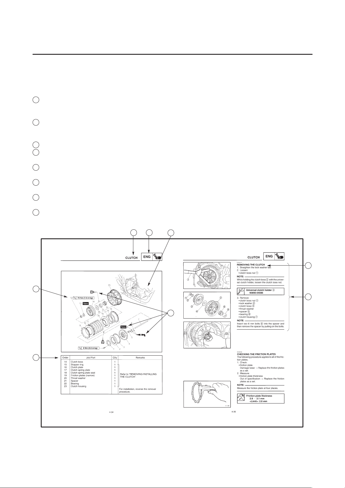
To help identify parts and clarify procedure steps, there are exploded diagrams at the start of each
removal and disassembly section.
5
Numbers are given in the order of the jobs in the exploded diagram. A circled number indicates a
disassembly step.
6
Symbols indicate parts to be lubricated or replaced.
Refer to “SYMBOLS”.
7
A job instruction chart accompanies the exploded diagram, providing the order of jobs, names of
parts, notes in jobs, etc.
8
Jobs requiring more information (such as special tools and technical data) are described sequentially.
12
5
7
4
3
8
6
1
GEN
INFO
3
CHK
ADJ
5
CARB
7
2
SPEC
4
ENG
6
CHAS
8
EAS00009
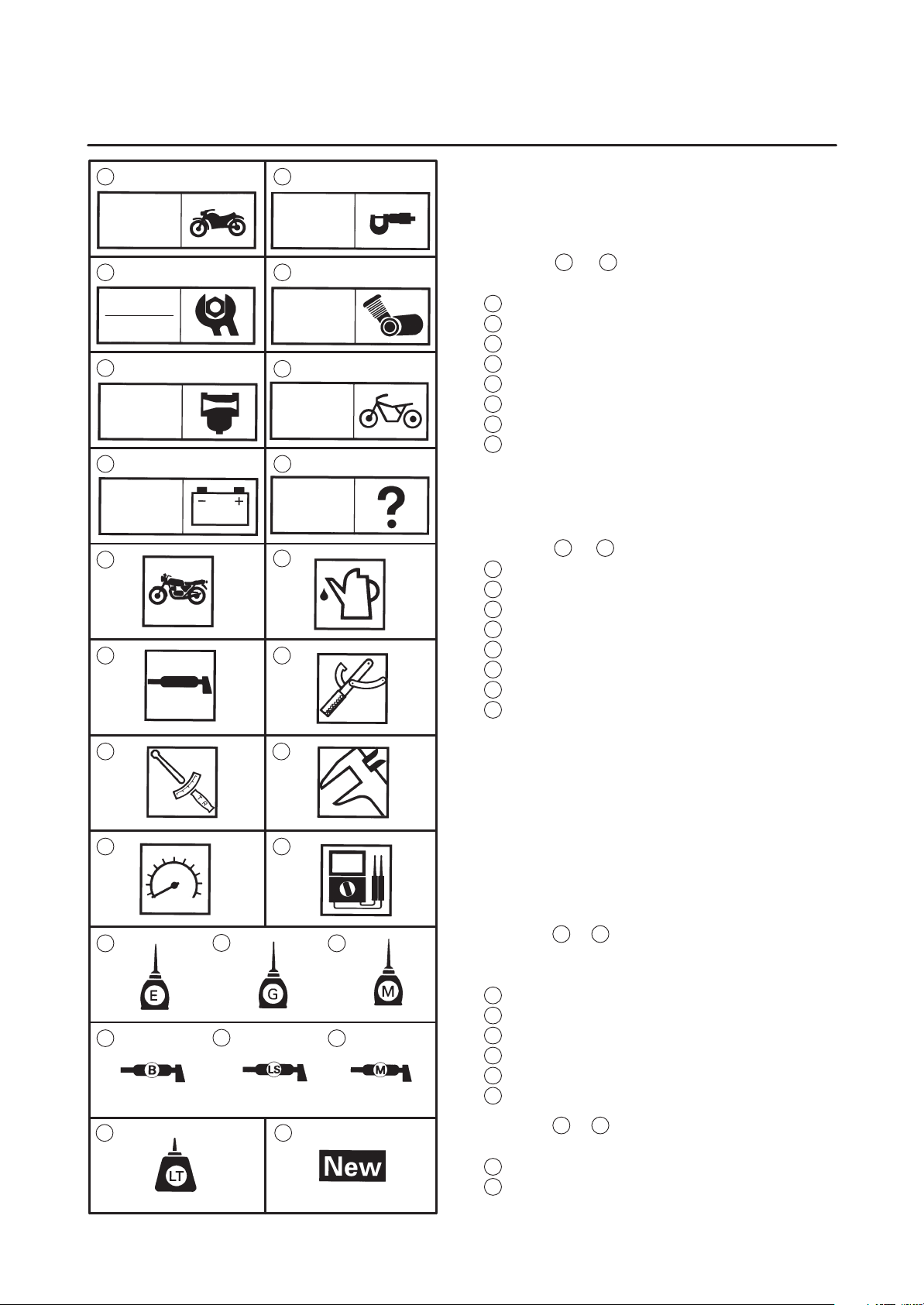
SYMBOLS
The following symbols are not relevant to every
vehicle.
Symbols
chapter.
General information
1
Specifications
2
Periodic checks and adjustments
3
Engine
4
Carburetor(-s)
5
Chassis
6
Electrical system
7
Troubleshooting
8
1
to 8 indicate the subject of each
ELEC
9
11 12
18 1917
21
10
1413
1615
TRBL
SHTG
2220
Symbols 9 to 16 indicate the following.
Serviceable with engine mounted
9
10
Filling fluid
11
Lubricant
12
Special tool
13
Tightening torque
14
Wear limit, clearance
15
Engine speed
16
Electrical data
Symbols 17 to 22 in the exploded diagrams indicate the types of lubricants and lubrication
points.
17
Engine oil
18
Gear oil
19
Molybdenum disulfide oil
20
Wheel bearing grease
21
Lithium soap base grease
22
Molybdenum disulfide grease
23 24
Symbols 23 to 24 in the exploded diagrams indicate the following:
23
Apply locking agent (LOCTITE)
24
Replace the part

CONTENTS
SPECIFICATIONS
GENERAL SPECIFICATIONS 1. . . . . . . . . . . . . . . . . . . . . . . . . . . . . . . .
MAINTENANCE SPECIFICATIONS 3. . . . . . . . . . . . . . . . . . . . . . . . . . .
ENGINE 3. . . . . . . . . . . . . . . . . . . . . . . . . . . . . . . . . . . . . . . . . . . . . . . .
CHASSIS 6. . . . . . . . . . . . . . . . . . . . . . . . . . . . . . . . . . . . . . . . . . . . . . .
ELECTRICAL 8. . . . . . . . . . . . . . . . . . . . . . . . . . . . . . . . . . . . . . . . . . .
CABLE ROUTING 9. . . . . . . . . . . . . . . . . . . . . . . . . . . . . . . . . . . . . . . . . .
PERIODIC INSPECTION AND ADJUSTMENT
INTRODUCTION 20. . . . . . . . . . . . . . . . . . . . . . . . . . . . . . . . . . . . . . . . . . .
PERIODIC MAINTENANCE/LUBRICATION INTERVALS 20. . . . . . .
ENGINE 22. . . . . . . . . . . . . . . . . . . . . . . . . . . . . . . . . . . . . . . . . . . . . . . . . . .
ADJUSTING THE CLUTCH LEVER 22. . . . . . . . . . . . . . . . . . . . . . . .
CHASSIS 23. . . . . . . . . . . . . . . . . . . . . . . . . . . . . . . . . . . . . . . . . . . . . . . . . .
ADJUSTING THE FRONT BRAKE 23. . . . . . . . . . . . . . . . . . . . . . . . .
CARBURETORS
AIR INDUCTION SYSTEM 24. . . . . . . . . . . . . . . . . . . . . . . . . . . . . . . . . . .
AIR INJECTION 24. . . . . . . . . . . . . . . . . . . . . . . . . . . . . . . . . . . . . . . . .
AIR CUTOFF VALVE 24. . . . . . . . . . . . . . . . . . . . . . . . . . . . . . . . . . . . .
AIR INDUCTION SYSTEM DIAGRAMS 25. . . . . . . . . . . . . . . . . . . . .
CHECKING THE AIR INDUCTION SYSTEM 26. . . . . . . . . . . . . . . .
CHASSIS
FRONT AND REAR BRAKES 27. . . . . . . . . . . . . . . . . . . . . . . . . . . . . . . .
FRONT BRAKE MASTER CYLINDER 27. . . . . . . . . . . . . . . . . . . . . .
ASSEMBLING AND INSTALLING THE
FRONT BRAKE MASTER CYLINDER 28. . . . . . . . . . . . . . . . . .
REAR BRAKE CALIPER 30. . . . . . . . . . . . . . . . . . . . . . . . . . . . . . . . . .
ELECTRICAL
CARBURETOR HEATING SYSTEM 32. . . . . . . . . . . . . . . . . . . . . . . . . .
TROUBLESHOOTING 33. . . . . . . . . . . . . . . . . . . . . . . . . . . . . . . . . . .
XJR1300 2002 WIRING DIAGRAM (for EUR)
XJR1300P 2002 WIRING DIAGRAM (for AUS)
GENERAL SPECIFICATIONS
SPECIFICATIONS
GENERAL SPECIFICATIONS
Model XJR1300 (P)
Model code: 5EAT/5EAW (EUR)
5EAU/ 5EAX (for D)
5EAV/ 5EAY (for AUS)
Dimensions:
Overall length
Overall width
Overall height
Seat height
Wheelbase
Minimum ground clearance
Minimum turning radius
Basic weight:
With oil and full fuel tank
Carburetor:
Type/ quantity
Manufacturer
2,175 mm
775 mm
1,115 mm
790 mm
1,510 mm
120 mm
2,800 mm
247 kg
BSR37/ 4
MIKUNI
SPEC
Transmission:
Primary reduction system
Primary reduction ratio
Secondary reduction system
Secondary reduction ratio
Transmission type
Operation
Gear ratio 1st
2nd
3rd
4th
5th
Spur gear
98/ 56 (1.750)
Chain drive
39/ 18 (2.167)
Constant mesh 5-speed
Left foot operation
40/ 14 (2.857)
36/ 18 (2.000)
33/ 21 (1.571)
31/ 24 (1.292)
29/ 26 (1.115)
1
Model XJR1300 (P)
Tire:
Type
Size front
rear
Manufacturer front
rear
Type front
rear
Tire pressure (cold tire):
Maximum load-except motorcycle
Loading condition A *
front
rear
Loading condition B *
front
rear
High-speed riding
front
rear
GENERAL SPECIFICATIONS
Tubeless
120/ 70ZR17 (58W)/
120/ 70ZR17 M/ C (58W)
180/ 55ZR17 (73W)/
180/ 55ZR17 M/ C (73W)
MICHELIN/ DUNLOP
MICHELIN/ DUNLOP
MACADAM90X E/D220F ST M
MACADAM90X E/D220 ST M
203 kg
0 X 90 kg
250 kPa (2.5 kg/ cm
250 kPa (2.5 kg/ cm
90 X 203 kg
250 kPa (2.5 kg/ cm
290 kPa (2.9 kg/ cm
250 kPa (2.5 kg/ cm
290 kPa (2.9 kg/ cm
2
, 2.5 bar)
2
, 2.5 bar)
2
, 2.5 bar)
2
, 2.9 bar)
2
, 2.5 bar)
2
, 2.9 bar)
SPEC
*Load is the total weight of cargo, rider, passenger, and accessories.
2
MAINTENANCE SPECIFICATIONS
MAINTENANCE SPECIFICATIONS
ENGINE
SPEC
Model
Cylinder head:
Warp limit
Cylinder:
Bore size
Taper limit
Out of round limit
Wear limit
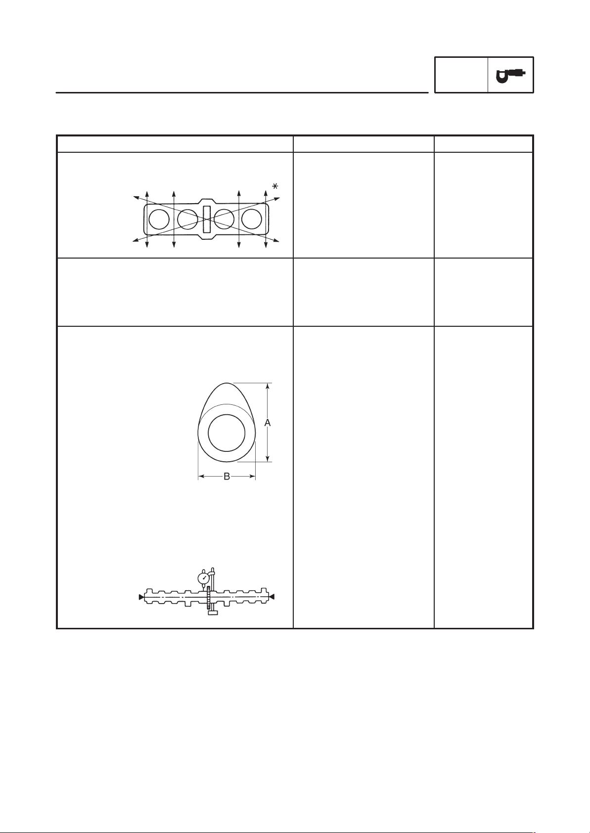
Camshaft:
Drive method
Cam cap inside diameter
Camshaft outside diameter
Shaft-to-cap clearance
Cam dimensions
Standard Limit
SSS 0.2 mm
79.00 X 79.01 mm
SSS
SSS
SSS
Chain drive (Center)
25.000 X 25.021 mm
24.967 X 24.980 mm
0.020 X 0.054 mm
SSS
0.05 mm
0.1 mm
79.1 mm
SSS
SSS
SSS
SSS
Intake “A”
“B”
Exhaust “A”
“B”
Camshaft runout limit
35.95 X 36.05 mm
28.058 X 28.158 mm
35.95 X 36.05 mm
28.045 X 28.145 mm
SSS
35.85 mm
27.958 mm
35.85 mm
27.945 mm
0.03 mm
3
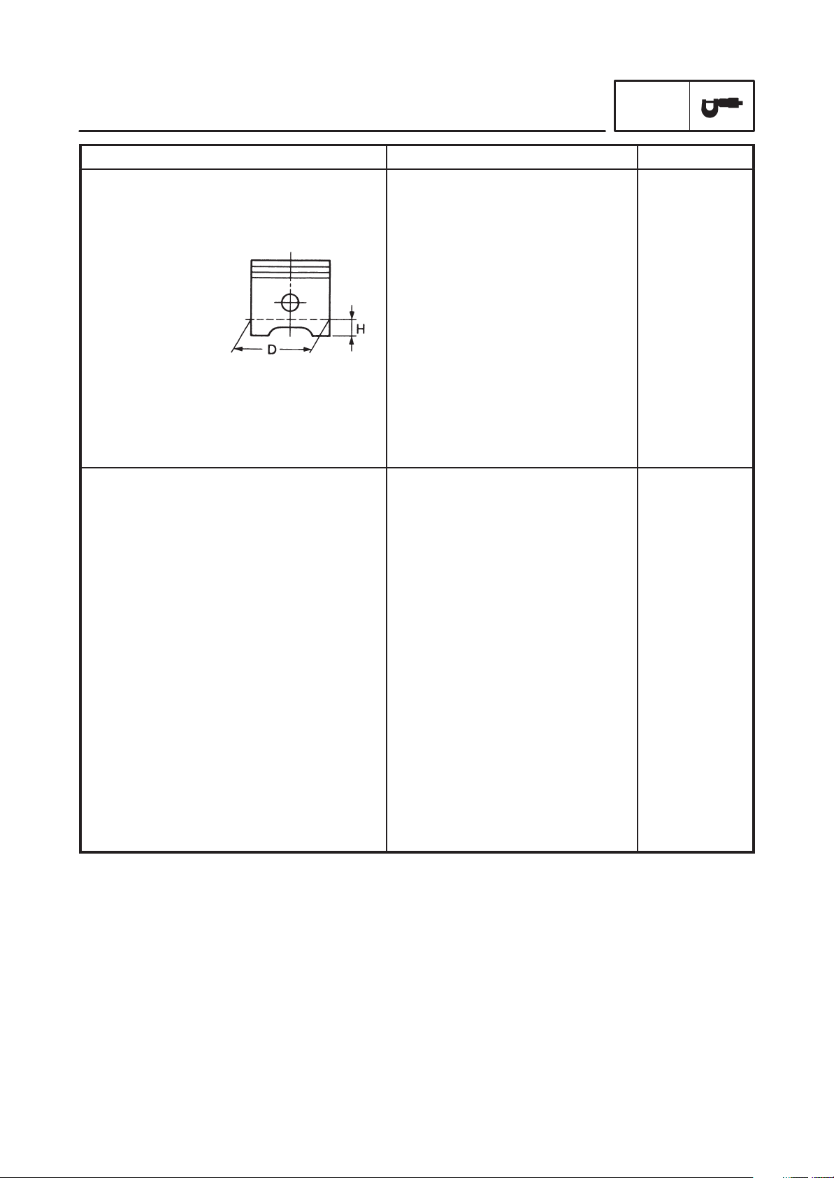
Model Standard Limit
Piston:
Piston to cylinder clearance
Piston size “D”
MAINTENANCE SPECIFICATIONS
0.015 X 0.040 mm
78.970 X 78.985 mm
SPEC
0.15 mm
SSS
Measuring point “H”
Piston off-set
Piston off-set direction
Piston pin bore inside diameter
Piston pin outside diameter
Carburetor:
I.D. mark
Main jet (M.J)
Main air jet (M.A.J)
Jet needle (J.N)
Needle jet (N.J)
Pilot jet (P.A.J.1)
Pilot outlet (P.O)
Pilot jet (P.J)
Bypass 1 (B.P.1)
Bypass 2 (B.P.2)
Bypass 3 (B.P.3)
Pilot screw (P.S)
Valve seat size (V.S)
Starter jet (G.S.1)
Starter jet (G.S.2)
Throttle valve size (Th.V)
Float height (F.H)
Fuel level (using special tool)
Engine idle speed
Intake vacuum
5 mm
1 mm
IN side
18.004 X 18.015 mm
17.991 X 18.000 mm
5EAT 30
#107.5
#80
5D118-53-3
P-0M
#140
ø1.0
#15
0.9
0.9
0.8
2
2.3
#52.5
0.8
#115
33 X 34 mm
3 X 4 mm
950 X 1,150 r/ min
31.3 kPa (235 mmHg)
SSS
SSS
SSS
18.045 mm
17.971 mm
SSS
SSS
SSS
SSS
SSS
SSS
SSS
SSS
SSS
SSS
SSS
SSS
SSS
SSS
SSS
SSS
SSS
SSS
SSS
SSS
4
Tightening torques
g
size
y
MAINTENANCE SPECIFICATIONS
SPEC
Part to be tightened
Carburetor joint and carburetor
Carburetor and air filter joint
Air induction system pipe joint
Air induction system
Part name
Band
Clamp
–
Bolt
Thread
M4 0.7
M4 0.7
–
M6 1.0
Q’ty
4
4
4
2
Tightening
torque
Nm mSkg
2.7
2.7
3.7
10
0.27
0.27
0.37
1.0
Remarks
5
CHASSIS
MAINTENANCE SPECIFICATIONS
SPEC
Model
Front suspension:
Front fork travel
Fork spring free length
Fitting length
Collar length
Spring rate (K1)
(K2)
Stroke (K1)
(K2)
Optional spring
Oil capacity
Oil level
Oil grade
Rear suspension:
Shock absorber travel
Spring free length
Fitting length
Spring rate (K1)
(K2)
(K3)
(K4)
Stroke (K1)
(K2)
(K3)
(K4)
Standard Limit
130 mm
308.3 mm
287.3 mm
245 mm
6.4 N/ mm (0.65 kg/ mm)
10.8 N/ mm (1.1 kg/ mm)
0 X 85 mm
85 X 130 mm
No
568 cm
118 mm
Fork oil 10W or equivalent
93 mm
230 mm
209 mm
19.4 N/ mm (1.98 kg/ mm)
21.4 N/ mm (2.18 kg/ mm)
26.3 N/ mm (2.68 kg/ mm)
28.2 N/ mm (2.88 kg/ mm)
0 X 13 mm
13 X 50 mm
50 X 67.5 mm
67.5 X 93.0 mm
3
SSS
300 mm
SSS
SSS
SSS
SSS
SSS
SSS
SSS
SSS
SSS
SSS
SSS
225 mm
SSS
SSS
SSS
SSS
SSS
SSS
SSS
SSS
SSS
Front wheel:
Type
Rim size
Rim material
Rim runout limit radial
lateral
Rear wheel:
Type
Rim size
Rim material
Rim runout limit radial
lateral
Drive chain:
Type/ manufacturer
No. of links
Chain free play
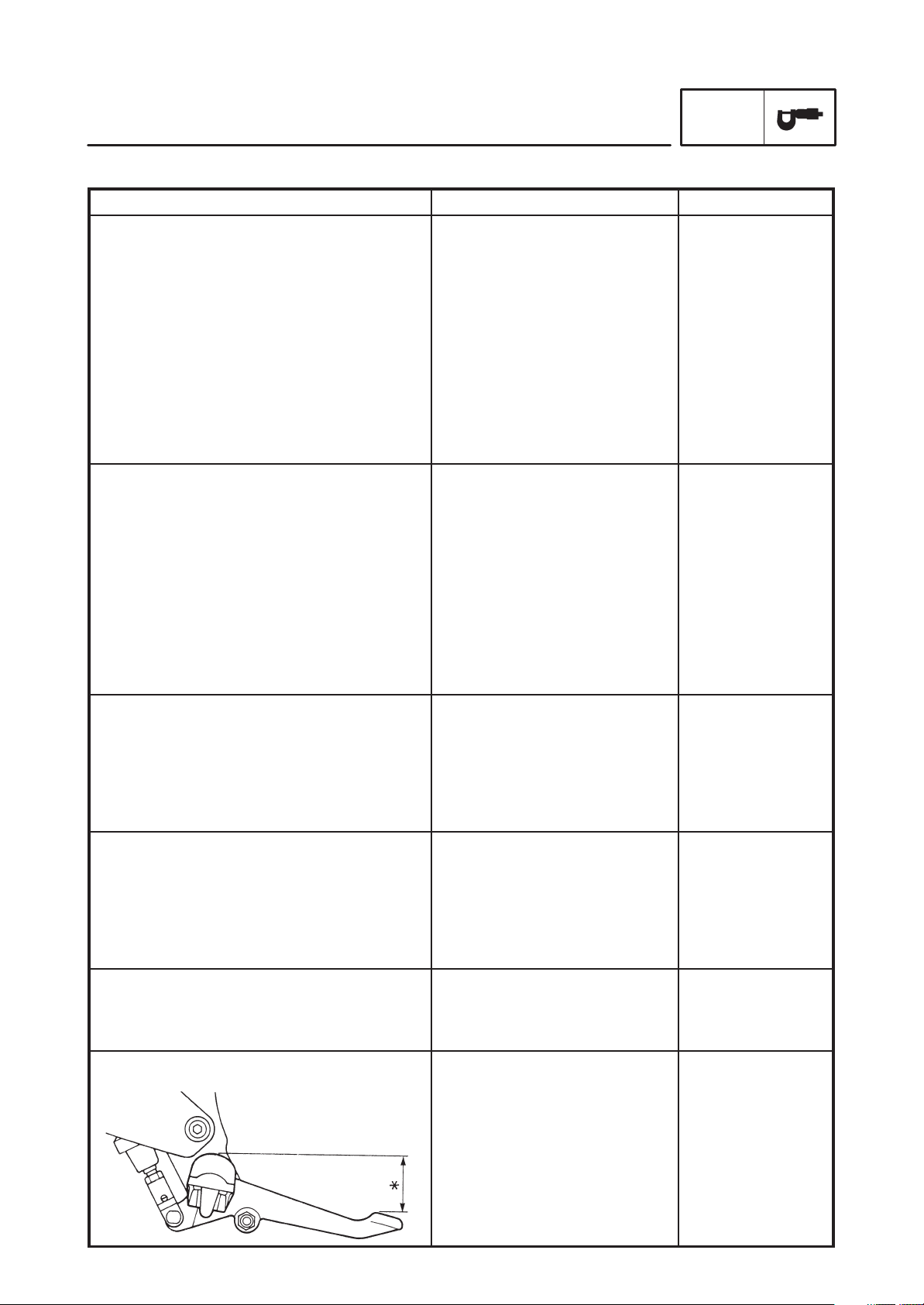
Brake lever & brake pedal:
Brake pedal position
Cast wheel
17 MT3.50 or
17 M/ C MT3.50
Aluminum
SSS
SSS
Cast wheel
17 MT3.50 or
17 M/ C MT3.50
Aluminum
SSS
SSS
50VA8/ DAIDO
112
20 X 30 mm
40 mm SSS
SSS
SSS
SSS
1 mm
0.5 mm
SSS
SSS
SSS
1 mm
0.5 mm
SSS
SSS
SSS
6
Tightening torques
g
y
Part to be tightened
MAINTENANCE SPECIFICATIONS
Part name Thread size Q’ty
SPEC
Tightening
torque
Nm mSkg
Remarks
Throttle cable and carburetor
Ignition coil
Nut
Nut
M6 1.0
M6 1.0
2
246.5
0.4
0.65
7
 Loading...