

Page 1

Getting Started
Owner’s Manual 1
Page 2

Getting Started
Contents
Precautions . . . . . . . . . . . . . . . . . . . . . . . . . . . . . . . . . . . . . . . . . . . . . . . . 4
About the Manuals . . . . . . . . . . . . . . . . . . . . . . . 6
■ The Getting Started Manual (this manual) . . . . . . . . . . . . . . . . . . . . . . . . 6
■ The Feature Reference Manual . . . . . . . . . . . . . . . . . . . . . . . . . . . . . . . . . 7
■ Conventions . . . . . . . . . . . . . . . . . . . . . . . . . . . . . . . . . . . . . . . . . . . . . . . . . 7
VL7 Basics . . . . . . . . . . . . . . . . . . . . . . . . . . . . . . 8
Essential Concepts for the VL7 User
■ What Are the Advantages? . . . . . . . . . . . . . . . . . . . . . . . . . . . . . . . . . . . . . 9
■ The VL7 Model . . . . . . . . . . . . . . . . . . . . . . . . . . . . . . . . . . . . . . . . . . . . 10
The Instrument . . . . . . . . . . . . . . . . . . . . . . . . . . . . . . . . . . . . . . . . 10
The Controllers . . . . . . . . . . . . . . . . . . . . . . . . . . . . . . . . . . . . . . . . 12
The Modifiers . . . . . . . . . . . . . . . . . . . . . . . . . . . . . . . . . . . . . . . . . 13
■ There’s More … . . . . . . . . . . . . . . . . . . . . . . . . . . . . . . . . . . . . . . . . . . . . 15
The Controls & Connectors . . . . . . . . . . . . . . . 16
A Brief Introduction To the VL7 Interface
■ Front Panel . . . . . . . . . . . . . . . . . . . . . . . . . . . . . . . . . . . . . . . . . . . . . . . . 17
■ Rear Panel . . . . . . . . . . . . . . . . . . . . . . . . . . . . . . . . . . . . . . . . . . . . . . . . . 20
Setting Up . . . . . . . . . . . . . . . . . . . . . . . . . . . . . 22
System Connections & Preparation
■ Power Supply . . . . . . . . . . . . . . . . . . . . . . . . . . . . . . . . . . . . . . . . . . . . . . 22
■ Controllers . . . . . . . . . . . . . . . . . . . . . . . . . . . . . . . . . . . . . . . . . . . . . . . . . 23
Breath Controller . . . . . . . . . . . . . . . . . . . . . . . . . . . . . . . . . . . . . . 23
Foot Controllers . . . . . . . . . . . . . . . . . . . . . . . . . . . . . . . . . . . . . . . 23
Foot Switches . . . . . . . . . . . . . . . . . . . . . . . . . . . . . . . . . . . . . . . . . 23
■ Audio Connections . . . . . . . . . . . . . . . . . . . . . . . . . . . . . . . . . . . . . . . . . . 23
Headphones . . . . . . . . . . . . . . . . . . . . . . . . . . . . . . . . . . . . . . . . . . . 23
Stereo Sound System . . . . . . . . . . . . . . . . . . . . . . . . . . . . . . . . . . . 24
■ MIDI Connections . . . . . . . . . . . . . . . . . . . . . . . . . . . . . . . . . . . . . . . . . . . 24
■ Power-on Procedure . . . . . . . . . . . . . . . . . . . . . . . . . . . . . . . . . . . . . . . . . 25
■ Play the Demo . . . . . . . . . . . . . . . . . . . . . . . . . . . . . . . . . . . . . . . . . . . . . . 26
■ Breath Controller Calibration . . . . . . . . . . . . . . . . . . . . . . . . . . . . . . . . . . 28
■ Load the Pre-programmed Voice Data . . . . . . . . . . . . . . . . . . . . . . . . . . 30
Loading the “FULLCNT1:All” Voice File . . . . . . . . . . . . . . . . . . 31
2
Page 3
Getting Started
Voice Selection . . . . . . . . . . . . . . . . . . . . . . . . . 34
Selecting & Playing the VL7’s 64 Voices
■ Using the Voice Directory . . . . . . . . . . . . . . . . . . . . . . . . . . . . . . . . . . . . 36
The Controllers . . . . . . . . . . . . . . . . . . . . . . . . .38
Natural Musical Nuance and Expressive Control
■ Physical Controllers . . . . . . . . . . . . . . . . . . . . . . . . . . . . . . . . . . . . . . . . . 39
■ VL7 Controller Parameters . . . . . . . . . . . . . . . . . . . . . . . . . . . . . . . . . . . . 40
■ Controller Views . . . . . . . . . . . . . . . . . . . . . . . . . . . . . . . . . . . . . . . . . . . . 41
■ Some Exercises With the Alto Sax Controllers . . . . . . . . . . . . . . . . . . . . 42
■ Controller Envelopes . . . . . . . . . . . . . . . . . . . . . . . . . . . . . . . . . . . . . . . . 46
■ Other Controller Views . . . . . . . . . . . . . . . . . . . . . . . . . . . . . . . . . . . . . . . 47
Mixing & The Modifiers . . . . . . . . . . . . . . . . . . 48
Creating New Timbres and Original Voices
Mixing . . . . . . . . . . . . . . . . . . . . . . . . . . . . . . . . . . . . . . . . . . . . . . . . . . . 48
■ An Exercise: Remix the Pan Pipes Voice . . . . . . . . . . . . . . . . . . . . . . . . 49
The Modifiers . . . . . . . . . . . . . . . . . . . . . . . . . . . . . . . . . . . . . . . . . . . . . 51
■ Harmonic Enhancer . . . . . . . . . . . . . . . . . . . . . . . . . . . . . . . . . . . . . . . . . . 51
■ Dynamic Filter . . . . . . . . . . . . . . . . . . . . . . . . . . . . . . . . . . . . . . . . . . . . . 54
■ Frequency Equalizer . . . . . . . . . . . . . . . . . . . . . . . . . . . . . . . . . . . . . . . . . 55
■ Impulse Expander . . . . . . . . . . . . . . . . . . . . . . . . . . . . . . . . . . . . . . . . . . . 56
■ Resonator . . . . . . . . . . . . . . . . . . . . . . . . . . . . . . . . . . . . . . . . . . . . . . . . . . 57
Effects . . . . . . . . . . . . . . . . . . . . . . . . . . . . . . . .58
Creating the Right Ambience
■ Modulation Effects . . . . . . . . . . . . . . . . . . . . . . . . . . . . . . . . . . . . . . . . . . 59
■ Feedback Delay Effects . . . . . . . . . . . . . . . . . . . . . . . . . . . . . . . . . . . . . . 59
■ Reverb Effects . . . . . . . . . . . . . . . . . . . . . . . . . . . . . . . . . . . . . . . . . . . . . . 60
Index . . . . . . . . . . . . . . . . . . . . . . . . . . . . . . . . . 62
3
Page 4

Getting Started
Precautions
!! PLEASE READ THIS BEFORE PROCEEDING !!
■ Location
Do not expose the instrument to the following
conditions to avoid deformation, discoloration, or more
serious damage.
• Direct sunlight (e.g. near a window).
High temperatures (e.g. near a heat source, outside,
•
or in a car during the daytime).
• Excessive humidity.
• Excessive dust.
Strong vibration.
•
■ Power Supply
• Turn the power switch OFF when the instrument is
not in use.
• The power supply cord should be unplugged from
the AC outlet if the instrument is not to be used
for an extended period of time.
Unplug the instrument during electric storms.
•
• Avoid plugging the instrument into the same AC
outlet as appliances with high power consumption,
such as electric heaters or ovens. Also avoid using
multi-plug adaptors since these can result in
reduced sound quality and possibly damage.
■ Turn Power OFF When Making Connections
• To avoid damage to the instrument and other devices
to which it is connected (a sound system, for
example), turn the power switches of all related
devices OFF prior to connecting or disconnecting
audio and MIDI cables.
● DANGER
Improper connection of the equipment-grounding
conductor can result in a risk of electric shock.
Do not modify the plug provided with the product
— if it will not fit the outlet, have a proper outlet
installed by a qualified electrician. Do not use an
adaptor which defeats the function of the equipment-grounding conductor. If you are in doubt as
to whether the product is properly grounded,
check with a qualified serviceman or electrician.
■ MIDI Connections
• When connecting the VL7 to MIDI equipment, be
sure to use high-quality cables made especially for
MIDI data transmission.
• Avoid MIDI cables longer than about 15 meters.
Longer cables can pick up electrical noise that can
causes data errors.
■ Handling and Transport
• Never apply excessive force to the controls,
connectors or other parts of the instrument.
• Always unplug cables by gripping the plug firmly,
not by pulling on the cable.
• Disconnect all cables before moving the instrument.
Physical shocks caused by dropping, bumping, or
•
placing heavy objects on the instrument can result in
scratches and more serious damage.
■ Cleaning
• Clean the cabinet and panel with a dry soft cloth.
• A slightly damp cloth may be used to remove
stubborn grime and dirt.
• Never use cleaners such as alcohol or thinner.
• Avoid placing vinyl objects on top of the instrument
(vinyl can stick to and discolor the surface).
■ Electrical Interference
• This instrument contains digital circuitry and may
cause interference if placed too close to radio or
television receivers. If this occurs, move the
instrument further away from the affected
equipment.
4
Page 5

Getting Started
■ Data Backup
• The VL7 contains a special long-life battery that
retains the contents of its internal memory even
when the power is turned OFF. The backup battery
should last for several years. When the backup
battery needs to be replaced “Change battery!” will
appear on the display when the power is turned on.
When this happens, have the backup battery replaced
by qualified Yamaha service personnel. DO NOT
ATTEMPT TO REPLACE THE BACKUP
BATTERY YOURSELF!
■ Handle Floppy Disks and the Disk Drive With
Care
• Use only 3.5” 2HD or 2DD type floppy disks.
• Do not bend or apply pressure to the floppy disk.
Do not open the shutter and touch the surface of
the floppy disk inside.
• Do not expose the disk to high temperatures. (e.g.
direct sunlight, a car interior, etc.)
• Do not expose the disk to magnetic fields.
Magnetic fields can partially or totally erase data
on the disk, rendering the disk unreadable.
• To eject a floppy disk, press the eject button
slowly as far as it will go then, when the disk is
fully ejected, remove it by hand.
The disk may not be ejected properly if the eject
button is pressed too quickly, or it is not pressed
in as far as it will go (the eject button may
become stuck in a half-pressed position and the
disk extends from the drive slot by only a few
millimeters). If this happens, do not attempt to
pull out the partially ejected disk. Using force in
this situation can damage the disk-drive mechanism or the floppy disk. To remove a partially
ejected disk, try pressing the eject button once
again, or push the disk back into the slot and then
repeat the eject procedure carefully.
• Do not insert anything but floppy disks into the
disk drive. Other objects may cause damage to the
disk drive or the floppy disk.
■ Service and Modification
• The VL7 contains no user serviceable parts. Opening
it or tampering with it in any way can lead to
irreparable damage and possibly electric shock.
Refer all servicing to qualified YAMAHA personnel.
■ Third-party Software
• Yamaha can not take any responsibility for
software produced for this product by third-party
manufacturers. Please direct any questions or
comments about such software to the manufacturer or their agents.
YAMAHA is not responsible for damage caused by improper handling or operation.
5
Page 6
Getting Started
About the Manuals
The VL7 comes with two manuals — Getting Started and Feature
Reference.
The Getting Started Manual (this manual)
The Getting Started manual contains seven chapters that take you through
essential information and procedures you will need to know to become familiar
with your VL7:
1. VL7 Basics [≥ Page 8]
Basic concepts you’ll need to understand in order to get the
most out of the VL7.
2. The Controls & Connectors [≥ Page 16]
Brief descriptions of the VL7 controls and connectors, and their
functions.
3. Setting Up [≥ Page 22]
System connections, powering up, playing the demo, calibrating
the Breath Controller, and loading the pre-programmed voices.
4. Voice Selection [≥ Page 34]
Several ways to select and play the VL7’s 64 voices.
5. The Controllers [≥ Page 38]
The VL7 controllers and how they can be assigned and edited
for optimum control.
6. Mixing & The Modifiers [≥ Page 48]
Customizing the sound to suit your own personal needs.
7. Effects [≥ Page 58]
An overview of the built-in digital effects that you can use to
add depth and ambience to the VL7 sound.
We recommend that you go through the chapters in sequence and actually
try out the various operations described. Once you’ve gone through the entire
Getting Started manual in this way, you should be familiar enough with the VL7
to need only the VL7 Feature Reference manual in future.
6
Page 7
Getting Started
The Feature Reference Manual
The Feature Reference manual is the “nuts and bolts” reference for
the VL7, individually describing its many functions in detail. The Feature
Reference manual is divided into 5 main sections, each describing the
various functions within a particular VL7 edit or utility mode.
1. General Operation [
2. Play Mode [
3. Edit Mode [≥ Page 21]
4. Utility Mode [≥ Page 149]
5. Appendix [≥ Page 177]
Once you have become familiar with the way the VL7 works by
going through the Getting Started manual, you should only need to refer to
the Feature Reference manual from time to time to get details on functions
you’ve never used before, or refresh your memory about functions that
you don’t use very often.
Each section of the Feature Reference manual has its own table of
contents, so you should be able to locate any particular function quickly
and easily. Functions and references can also be located by referring to the
index at the back of the manual.
≥ Page 13]
≥ Page 7]
Conventions
The following conventions are used through the VL7 manuals to avoid
confusion and make the text easier to read.
Buttons & Controls
Button and control names used on the VL7 panel appear in the text
in capital letters within square brackets: “the [ button”, for
example.
Parameter Names
Parameter names and other labels which appear on the VL7 display
are printed in the courier typeface for easier identification: for
example, “adjust the “Balance” parameter as required”.
Parameter Ranges
An ellipsis is used to indicate a range of parameter values: e.g. “0
… 127”. This minimizes the confusion sometimes caused by the use
of a hyphen or dash for this purpose.
7
Page 8
Getting Started
VL7 Basics
Essential Concepts for the VL7 User
ike its predecessor, the VL1, the Yamaha VL7 Virtual Acoustic
Synthesizer produces sound in an entirely new way. It has no
L
In fact, it uses none of the sound generation concepts employed in
conventional synthesizers. The VL7 represents an advanced application of
computer-based “physical modeling” in musical sound synthesis.
systems or the flight characteristics of aircraft in the design stage, the VL7
simulates the very complex vibrations, resonances, reflections and other
acoustic phenomena that occur in a real wind or string instrument. This
requires a tremendous amount of computer processing power (weather and
aerodynamic modeling require room-filling super computers), and radical
advances in microprocessor speed and capability plus some very
sophisticated Yamaha technology were necessary to achieve the real-time
sound generation capabilities exhibited by the VL7 Virtual Acoustic
Synthesizer.
oscillators or function generators, no preset waveforms or samples.
In the same way that computer models are used to simulate weather
8
Page 9

Getting Started
What Are the Advantages?
he VL7 offers many advantages in terms of musical performance.
Not just in terms of sound, but also in terms of the “behavior” that
T
because someone has programmed a certain sound or pattern of behavior
into it. The physical model can be programmed to have certain attributes
— the length of a pipe or the stiffness of a reed, for example — but the
actual sound produced by any configuration can only be accurately
determined by playing it. Of course, the same applies to the design of
acoustic instruments. Because of its natural acoustic behavior the VL7 is
undoubtedly a little harder to play than conventional synthesizers, but
when mastered this is the very characteristic that is its greatest strength.
The Yamaha VL7 is the most musical synthesizer ever made. A soloist’s
dream!
makes acoustic instruments so … well, musical! But this is not
• The VL7 sounds better, has more depth, and is more realistic in
the musical sense than any other synthesizer system.
• Simply pressing a key in the same way does not always produce
precisely the same sound. The instrument is responsive and
“alive”.
• Simply pressing a key in the same way does not always produce
precisely the same sound. The instrument is responsive and
“alive”.
• It has extraordinary expressive capability. Rather than simply
controlling parameters like volume or pitch, you can control
characteristics such as breath and reed pressure with appropriate
complex effects on the timbre of the sound.
9
Page 10
T
Getting Started
The VL7 Model
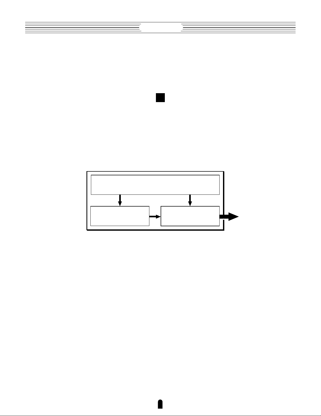
he overall VL7 model or “algorithm” consists of three main blocks:
the instrument, controllers, and modifiers. In schematic form these
blocks are arranged as follows:
The VL7 Voice "Element"
Controllers (also envelopes)
Instrument
●
The Instrument
The key block in this algorithm is the instrument, since it is here that
the fundamental tone or “timbre” of the sound is defined. The extreme
complexity of this portion of the model makes it unsuitable for user
programming, so various instruments for the VL7 are provided in the form
of pre-programmed voices. These are primarily woodwind, brass, and
string voices, since the VL7’s physical model is capable of most
accurately simulating the sound-generating mechanism of all three
instrument categories.
The instrument model consists primarily of a driver — the reed/
mouthpiece, lip/mouthpiece, or bow/string system — and a resonant
system corresponding to the tube and air column or string.
Modifiers
Sound
out.
10
Page 11

Getting Started
In all these
instruments
pressure
applied here
(the driving
point) causes
vibration which
results in
sound.
The sound thus
produced is amplified
and sustained
by the body of
the instrument.
Reed vibration.
Lip vibration.
Air vibration.
String vibration.
The pitch of the sound is determined
by the length of the air column or
string, and the timbre is a complex
product of the driving source (reed,
lip, air, string), the shape of the
resonant cavity, the materials from
which the instrument is made, etc.
One of the remarkable features of the VL7’s Virtual Acoustic Synthesis
system is that just about any driver can be used with any type of pipe or string.
Drivers Pipes/String
11
Page 12

Getting Started
●
The Controllers
The input to an acoustic wind instrument comes from the player’s lungs, trachea,
oral cavity, and lips. In a string instrument it comes from the players arm movement,
transmitted to the string via a bow. These elements actually form an important part of the
sound generating system and, in the VL7 model, are included in the controllers block.
The player also influences the sound of the instrument by playing the keys, tone holes, or
frets, and this aspect of control constitutes another part of the controllers block. These
and other control parameters provided by the VL7 are listed in the illustration below.
In essence, the controller parameters determine how the instrument “plays”. All of
these parameters can be assigned to any of the external controllers that can be used with
the VL7: breath controller, foot controller, modulation wheels, etc. The pressure
parameter, for example, will normally be assigned to a breath controller so the player can
control the dynamics of the instrument by varying the breath pressure applied to the
controller — a natural, instinctive way to play wind-instrument voices. At the same time
the growl and throat parameters might also be assigned to the breath controller in order
to achieve life-like response and effects.
Controls the characteristics
of the "player's" throat or bowing arm.
Pressure
The amount of breath pressure
applied to the reed or mouthpiece,
or bow velocity applied to the string".
Embouchure
The tightness of the lips against
the reed or against each other, or
the force of the bow against the
string.
Pitch
Changes the length of the
air column or string, and thereby
the pitch of the sound.
Throat
Growl
A periodic pressure (bow
velocity) modulation which
produces the "growl" effect
often heard in wind instruments.
Tonguing
Simulates the half-tonguing
technique used by saxophone
players by changing the "slit"
of the reed.
Scream
Drives the entire system into
chaotic oscillation, creating
effects that can only be
achieved with physical
modelling technology.
Damping & Absorption
Simulate the effects of air friction
in the pipe or on the string,
and of high-frequency losses
at the end of the pipe or string.
12
Page 13

Getting Started
●
The Modifiers
Although you don’t have direct programming access to the VL7
instrument block, the modifiers allow a significant degree of control over the
final timbre of the voice. The modifiers block consists of 5 sections as shown in
the diagram. Although these may appear to be simple effects, they are actually
intimately related to the VL7’s sound-producing model and have a significant
effect on the sound (the VL7 has a separate effects stage with reverb, delay, and
modulations effects — see page 58).
Harmonic Enhancer
The Harmonic Enhancer allows you to
manipulate the harmonic structure of the
In
sound to the extent that you can create
radical timbral variations within the current
instrument “family” (e.g. saxes).
Harmonic
Enhancer
[Page 51]
Dynamic Filter
This section is similar to the dynamic filters
found in many conventional synthesizers. It
has selectable high-pass, bandpass, band
elimination, and low-pass modes, and a
“wet/dry” balance parameter which allows
delicate variations in the degree of filtration
applied. Another important feature is
keyboard cutoff tracking which varies the
cutoff frequency according to the key
played. [Page 54]
Frequency Equalizer
This is a 5-band parametric equalizer with
frequency, Q (bandwidth), and level
control. The equalizer also has pre-EQ
high- and low-pass filters as well as key
scaling capability for precise response
control throughout the instrument’s range.
[Page 55]
Dynamic
Filter
Frequency
Equalizer
Impulse
Expander
Resonator
Out
13
Page 14

Getting Started
Impulse Expander
The Impulse Expander works in conjunction with the Resonator, described
below, to simulate the effect of an instrument’s resonant cavity or sound
box. It can also be used to simulate the acoustic environment in which the
instrument is played. In contrast to the Resonator, the Impulse Expander is
more suited to the simulation of metallic resonances and is thus invaluable
for refining the sound of brass and metal-bodied woodwinds. Other
important effects are the ability to diffuse sharp attack sounds and to give
depth and realism to vibrato. [Page 56]
Resonator
While the Impulse Expander and even the Harmonic Enhancer tend to give
the sound a metallic quality, the Resonator produces a more woody
resonance effect. Careful adjustment of the resonator’s parameters can
often bring a not-quite-right voice to life. [Page 57]
14
Page 15

Getting Started
There’s More …
n this brief introduction to VL7 basics we’ve only looked at the
central physical model which is the key the VL7’s unprecedented
I
sound and musical performance. There’s also an extensive range of
other functions and features that are similar to those you may be familiar
with from conventional synthesizers. There are, for example, a range of
programmable envelopes that can be applied to most of the controllers in
addition to real-time player control. And, of course, there’s a
comprehensive selection of MIDI, disk, and other utility functions that
give the VL7 maximum versatility and convenience.
Now that you understand the basics, dive in and find out what the
VL7 can really do.
15
Page 16

Getting Started●The Controls & Connectors
The Controls & Connectors
A Brief Introduction To the VL7 Interface
The following brief descriptions of the VL7 controls and connectors
should help you to understand the overall logic of the interface.
q MODE Buttons
w
C Button
@0
!8
PHONES Jack
Floppy Disk Drive
!5
OCTAVE _
and + Buttons
!9
Breath Controller Jack
r
DOWN UP
OCTAVE
VOLUME Control
LR
12
OUTPUT
FOOT CONTROLLER
MODE
EDIT UTILITY COPY STORE
PLAY
COMPARE
VOLUME CS1 CS2
1
FOOT SWITCH
e
S Button
t
Continuous Sliders
2
IN THRU
– and ≠
OUT
MIDI
F1 F2 F3 F4 F5 F6 F7 F8 CONT
PHONES
BREATH
PITCH MODULATION 1 MODULATION 2
!6
π Wheel
16
!7
“ and
‘ Wheels
u
¡ through •
Function Buttons
Page 17

Getting Started●The Controls & Connectors
Front Panel
y LCD Display & ÷ Control
i Data Dial
!0
= and - Buttons
The Controls & Connectors
q MODE Buttons
The P, E, and U buttons select the corresponding VL7 modes. The
PLAY mode lets you select and play voices, the EDIT mode gives you programming
access to the VL7’s voice and controller parameters, and the UTILITY mode includes
MIDI, disk, system and other functions that are essential for general operation.
☛ Feature Reference page 8.
w C Button
This button is used to copy voice parameters for fast, efficient editing.
☛ Feature Reference page 24.
e S Button
Used to store edited data to an internal memory location.
☛ Feature Reference page 27.
POWER
ON / OFF
A
B
C
D
1
2
3
4
5
6
7
INCDEC
9
ENTEREXIT
10
ALL
HE
DF
MODIFIER ON / OFF
ALL
MOD
11
12
EQ
EFFECT ON / OFF
13
14
IE
RSN
8
FBD
REV
15
16
!2
Bank a through
d Buttons
!3
Voice Number 1
through ^ Buttons
o
Cursor Buttons
!1
] and [ Buttons
!4
Keyboard
17
Page 18

Getting Started●The Controls & Connectors
r VOLUME Control
Adjusts the volume of the sound delivered via the rear-panel OUTPUT L and R
jacks as well as the PHONES jack.
☛ Getting Started page 25.
t – and ≠ Continuous Sliders
These controls can be assigned to a range of controller parameters for real-time
expressive control.
☛ Getting Started page 47. Feature Reference page 19.
y LCD Display & ÷ Control
This large multi-function liquid crystal display panel shows all parameters and
prompts you need to operate the VL7 with optimum ease and efficiency.
Use the ÷ (contrast) control located near the lower right-hand corner of the
display to achieve the best display visibility (LCD visibility varies greatly with viewing
angle and lighting).
☛ Getting Started page 34. Feature Reference page 14.
u ¡ through • Function Buttons
The functions of these buttons depend on the selected mode. They are used to
engage a function indicated on the display immediately above the button, select a page of
parameters, scroll through a list of parameters, and more.
☛ Feature Reference page 9.
i Data Dial
The data dial provides a fast, efficient way to cover a broad range of voice numbers
when, for example, you’re looking for a voice but don’t know the voice number. It’s also
handy for making large value changes in any of the edit modes.
☛ Getting Started page 35. Feature Reference page 16.
o Cursor Buttons
These 4 buttons move the “cursor” around the display screen, highlighting the various
items that are available for selection or parameters that are available for editing (the VL7
cursor appears as a dark block with inverse characters).
☛ Getting Started page 32. Feature Reference page 10.
!0 = and - Buttons
Used to select voices and edit parameter values in any of the VL7 edit modes.
Either button can be pressed briefly for single stepping in the specified direction, or held
for continuous scrolling. These buttons are also used to respond “Yes” or “No” to the
“Are You Sure?” confirmation prompt when required.
☛ Getting Started page 35. Feature Reference page 16.
!1 ] and [ Buttons
The ] button can generally be used to exit from any sub-mode or function,
while the [ button is used to engage a variety of modes and functions.
☛ Getting Started page 26. Feature Reference page 10.
!2 Bank a through d Buttons
The VL7 has 64 internal voice memory locations arranged in 4 banks of 16 voices
each. These buttons select the voice bank from which an individual voice will be selected.
☛ Getting Started page 35. Feature Reference page 15.
18
Page 19

Getting Started●The Controls & Connectors
!3 Voice Number 1 through ^ Buttons
The voice number buttons are used in conjunction with the bank buttons to select
any of the VL7’s 64 internal voice memory locations. When editing voice parameters
they are also used to turn effects and modifiers on or off.
☛ Getting Started page 35. Feature Reference page 15.
!4 Keyboard
The VL7 has a 49-key keyboard that is both velocity and after-touch sensitive for
broad, intimate expressive control.
!5 OCTAVE _ and + Buttons
Shift the pitch of the keyboard up or down one octave. A utility “Octave Hold”
function provides two modes: shift only while the button is held, or press once to shift
and again to release. MIDI note output data is also shifted.
☛ Feature Reference page 151.
!6 π Wheel
This self-centering pitch wheel allows realistic upward and downward pitch bends.
The pitch wheel can also be assigned to any of the VL7’s extensive range of controller
parameters for sophisticated expressive control.
☛ Getting Started page 39.
!7 “ and ‘ Wheels
Can be assigned to any of the VL7’s extensive range of controller parameters for
extraordinary expressive control. The ‘ wheel features a center-click position.
☛ Getting Started page 39. Feature Reference page 154.
The Controls & Connectors
!8 PHONES Jack
Accepts a standard pair of stereo headphones (1/4" stereo phone plug) for
headphone monitoring of the VL7 sound without the need for external amplification
equipment.
☛ Getting Started page 23.
!9 Breath Controller Jack
Plug the Yamaha BC2 Breath Controller supplied with the VL7 in here (an optional
BC1 Breath Controller may also be used).
☛ Getting Started page 23.
@0 Floppy Disk Drive
The VL7’s built-in floppy disk drive allows easy, economical, high-volume storage of
voice data. The disk-in-use indicator below the drive slot lights while any disk operation is in
progress (NEVER attempt to remove a disk or turn the power off while a disk operation is in
progress). The eject button, also below the disk slot, is used to remove disks from the drive.
☛ Getting Started page 5, 31. Feature Reference page 162.
19
Page 20

Getting Started●The Controls & Connectors
YAMAHA
MODEL VL7
AC INLET
@1
AC Power Cord
Socket
POWER
ON / OFF
@2 POWER Switch
Rear Panel
@1 AC Power Cord Socket
Be sure the plug the VL7’s AC power cord into this socket
power cord into an AC outlet.
☛ Getting Started page 22.
@2 POWER Switch
Press to turn power ON or OFF.
MIDI
THRU OUT
@6
MIDI IN, OUT and
IN
THRU Connectors
FOOT SWITCH
21
FOOT CONTROLLER
21
OUTPUT
R
@3
@4
FOOT CONTROLLER 1 and 2 Jacks
@5
FOOT SWITCH 1 and 2 Jacks
L
OUTPUT L and R Jacks
before plugging the
@3 OUTPUT L and R Jacks
These are the main stereo outputs from the VL7. Be sure to connect both outputs to the
appropriate channels of a stereo sound system in order to appreciate the full quality of the
VL7 sound and effects.
☛ Getting Started page 24.
@4 FOOT CONTROLLER 1 and 2 Jacks
These jacks accept Yamaha FC7 Foot Controllers which can be used to control any of
the VL7’s controller parameters. One FC7 Foot Controller is supplied with the VL7, and this
should normally be plugged into the FOOT CONTROLLER 2 jack. The second FC7 foot
controller is optional.
☛ Getting Started page 23.
@5 FOOT SWITCH 1 and 2 Jacks
An optional Yamaha FC4 or FC5 footswitch can be connected to one or both of
these jacks for sustain, portamento, and other control functions.
☛ Getting Started page 23.
@6 MIDI IN, OUT and THRU Connectors
The MIDI IN connector receives the data from an external sequencer or other MIDI
device which is to control or transmit data to the VL7. The MIDI THRU connector
simply re-transmits the data received at the MIDI IN connector, allowing convenient
chaining of MIDI devices. The MIDI OUT connector transmits data corresponding to all
VL7 performance operations, or bulk data when one of the MIDI data transmission
functions are activated.
☛ Getting Started page 24.
20
Page 21

Getting Started●The Controls & Connectors
The Controls & Connectors
21
Page 22

Getting Started●Setting Up
Setting Up
System Connections & Preparation
Audio
Foot
Controller
DOWN UP
OCTAVE
PITCH MODULATION 1 MODULATION 2
LR
OUTPUT12FOOT CONTROLLER
MODE
PLAY
EDIT UTILITY COPY STORE
COMPARE
VOLUME CS1 CS2
2
1
FOOT SWITCH
OUT
IN THRU
MIDI
F1 F2 F3 F4 F5 F6 F7 F8 CONT
Foot
Switch
A
1
INCDEC
9
ENTEREXIT
ALL
MIDI
POWER
ON / OFF
B
C
D
2
3
4
5
6
7
8
ALL
MOD
FBD
REV
EFFECT ON / OFF
10
11
12
13
14
15
16
HE
DF
EQ
IE
RSN
MODIFIER ON / OFF
Power Supply
Breath ControllerHeadphones
Power Supply
Before making any other connections the “female” end of the AC power cord
supplied with the VL7 should be firmly plugged into the rear-panel AC cord socket.
Ideally the power cord should then be plugged into a convenient AC outlet after you’ve
made all other necessary connections and placed the VL7 in the position in which it will
be used. Always make sure that the POWER switch is in the OFF (extended) position
before plugging the power cord in an AC outlet.
CAUTION! ■ Make sure your VL7 is rated for the AC voltage supplied in the
area in which it is to be used (as listed on the rear panel). Connecting the VL7 to
the wrong AC supply can cause serious damage to the internal circuitry and may
CAUTION!
even pose a shock hazard!
22
Page 23

Controllers
●
Breath Controller
The Breath Controller is an essential expressive tool — both for realistic expression
with wind-instrument voices and unprecedented expressive control with string voices.
Plug the BC2 Breath Controller supplied with the VL7 (or an optional BC1 breath
controller) into the front-panel breath controller jack. The Breath Controller is ideal for
controlling parameters that would normally be affected by a wind player's breath:
dynamics, timbre, pitch, and others.
Once you've set up your system and begin playing, refer to “Breath Controller
Calibration” on page 28 for instructions on calibrating your Breath Controller for optimum control precision and ease.
NOTES ■ For more information on Breath Controller setup and operation, see
the instructions packed with the supplied BC2 Breath Controller.
Getting Started●Setting Up
Setting Up
●
Foot Controllers
Although the VL7 has jacks for two foot controllers, it is not necessary to use both.
To begin with plug the supplied FC7 Foot Controller into the rear-panel FOOT
CONTROLLER 2 jack.
If you purchase a second FC7 Foot Controller for extra control capability, plug it
into the FOOT CONTROLLER 1 jack.
NOTES ■ For more information on Foot Controller setup and operation,
see the instructions packed with the supplied FC7 Foot Controller.
●
Foot Switches
The use of one or two footswitches allows sustain portamento switching. We
recommend that you purchase at least one Yamaha FC4 or FC5 Footswitch for this
purpose. A single footswitch can be plugged into either the rear-panel FOOTSWITCH 1
or 2 jack.
Audio Connections
●
Headphones
For private listening and practice headphones are ideal. You don’t have to hook up
and complete sound system, and you won’t disturb the neighbors no matter how loud or
late you play. Recommended Yamaha headphones for VL7 monitoring are the HPE-170,
HPE-160, or HPE-150 Stereo Headphones. Any standard pair of stereo headphones with a
1/4” stereo phone plug and an impedance of between about 8 and 150 ohms can be used.
23
Page 24

Getting Started●Setting Up
●
Stereo Sound System
The VL7 voices and effects are designed to sound their best in stereo, so you should
always use a stereo sound system to appreciate the full impact of the VL7 voices and
expressive features. The VL7 OUTPUT L and R jacks can be connected directly to musical
instrument amplifiers designed for keyboard use, or to the line inputs of a mixing console. It
is also possible to connect the VL7 outputs directly to the inputs of a multitrack or stereo tape
recorder.
The normal output level and impedance of the VL7 outputs are 2.5 ± 2 dBm and
10 kΩ.
NOTES ■ If you need to drive a mono amp or other device the VL7 output can
be switched to monaural — the same signal appears at the L and R outputs —
by using the Output parameter described on page 152 of the Feature Reference
manual.
■ Make sure that both the VL7 and your sound system are turned OFF when
making connections.
MIDI Connections
Like any other MIDI instrument the VL7 can be used with MIDI tone generators,
sequencers, computer software, and controllers for virtually unlimited system expansion
and control capability. You might, for example, like to control it from a Yamaha wind
controller such as the WX11 rather than the keyboard for even more realistic windinstrument feel and expression.
To ensure reliable error-free transmission of MIDI data always use high-quality
MIDI cables obtained from your Yamaha dealer or music equipment store. Also avoid
MIDI cables that are longer than about 15 meters, since cables longer than this can pick
up noise which can cause data errors.
The VL7 MIDI transmit channel, receive channel, local on/off, and device number
parameters are available in the utility mode “MIDI Setting” page described on page 153
of the Feature Reference manual. Make sure these parameters are set to match the corresponding settings of the external MIDI device(s) used with the VL7.
● The VL7 transmits and receives the following MIDI data:
Note
Control Change
Program Change
Aftertouch
Pitch Bend
Bulk
The played key(s) and velocity value.
Modulation wheel, foot controller, breath controller, and other controller
data.
Voice numbers from 1 to 64.
Keyboard aftertouch pressure.
Pitch bend wheel position.
Voice and system parameters transmitted in the form of “bulk dumps.”
24
Page 25

Getting Started●Setting Up
NOTES ■ For detailed MIDI specifications refer to the “MIDI Data Format”.
■ When using the VL7 with other MIDI equipment, it is a good idea to refer to
the MIDI specifications (implementation chart, MIDI data format) of the
equipment used to ensure compatibility.
Power-on Procedure
Always follow proper procedure when powering-up a sound system to minimize the
possibility of damage to the equipment (and your ears!).
1. Make sure your sound system’s main level/volume control(s) and the VL7 volume
control are turned all the way down prior to turning power on.
2. Turn on the VL7.
3. Turn on the sound system.
4. Raise the sound system volume to a reasonable level.
Setting Up
5. Gradually raise the VL7 VOLUME control while playing the keyboard to set the
desired listening level.
NOTES ■ The VL7 automatically transmits MIDI control change data correspond-
ing to its control status when its power switch is turned ON. This data can be
received and used by compatible MIDI equipment connected to the VL7 MIDI
OUT connector if the receiving equipment is turned on
before the VL7.
25
Page 26

Getting Started●Setting Up
Play the Demo
Once you’ve set up your VL7 system, you might like to play the pre-programmed demo
sequence to hear how some of the voices sound. This process will also help to familiarize you
with some of the VL7’s selection and editing procedures.
1. Select the Utility Mode System Page
Press the U button to select the utility mode.
2. Select the Demo Page
Press the ∞ button to select the “Demo” page.
3. Press [ and Confirm
Press the [ button if it’s OK to go ahead with the demo. The VL7 will ask
you to confirm again: press - to continue or = to abort.
NOTES ■ If the currently selected voice has been edited but not stored, the edit
data will be lost when the demo mode is engaged. Make sure the current voice
has been stored before entering the demo mode.
■ If the UTILITY mode “
Reference manual, page 156), the “
Confirm
” parameter is turned “
Are You Sure?
” prompt will not appear.
off
” (Feature
26
Page 27

Getting Started●Setting Up
4. Select a Song
Use the data dial or = and - buttons to select the song number you want to
start with.
• 16 demo pieces are provided. The last of these can be used with full accompaniment if the VL7 is connected to a GM (General MIDI) tone generator such
as the Yamaha TG300. Connect the VL7 MIDI OUT connector to the MIDI
IN connector of the GM tone generator.
5. Run the Demo
Press the • button to run the demo. Playback will start with the selected song,
then all other songs will be played in sequence. The cycle will repeat until stopped.
Setting Up
6. Stop the Demo
Press the ¶ button to stop demo playback.
7. Return To the Play Mode When Done
Press the MODE P button to return the PLAY mode.
27
Page 28

Getting Started●Setting Up
Breath Controller Calibration
Proper operation of the breath controller is vital to achieving the best possible sound
from the VL7. Although the controller is factory-calibrated to match most requirements,
we recommend that you carefully calibrate the breath controller for optimum performance
with your own playing style.
1. Make Sure the Breath Controller Is Connected
Make sure the breath controller is properly connected: turn the power OFF, plug in
the breath controller, then turn the power ON.
2. Select the Utility Mode System Page
Press the U button to select the utility mode. Then, if it is not already selected when the utility mode display appears, press the ¡ button to select the “Sys-
tem” function page.
3. Go To the Utility Mode Curve Page and Select “Brth”
Use the cursor keys to move the cursor to “5:Curve”, then press [ to call
the “Curve” function page. When the curve display appears press the • function
button (“Brth”) to call the breath controller curve page.
4. Adjust the Breath Controller Offset
The following adjustment must be performed while not blowing into the breath
controller mouthpiece. Do not hold the breath controller in your mouth.
Rotate the breath controller OFFSET trimmer slowly clockwise, using the supplied
screwdriver, until the vertical cursors above and below the curve graph move slightly to
the right and the number below the graph is greater than “0”. Then slowly rotate the
trimmer carefully counter-clockwise until the number below the graph just reaches “0”
(the cursors will be lined up with the left end of the graph), then stop. This completes the
offset adjustment.
28
Page 29

Getting Started●Setting Up
5. Adjust the Breath Controller Gain
Place the breath controller mouthpiece in your mouth and blow — notice that the
cursors move to right and the number below the graph increases according to how hard
you blow. Rotate the breath controller GAIN trimmer counter-clockwise as far as it will
go (don’t force it!) then, while blowing into the mouthpiece using the
you intend to use while playing, rotate the trimmer slowly clockwise until the number
below the graph just reaches “127” (the cursors should just line up with the right end of
the graph) and then stop. This completes the gain adjustment. Since changing the gain
can sometimes affect the offset setting, it is a good idea to repeat steps 4 and 5 until both
the offset and gain are set precisely as required.
NOTES ■ In addition to calibrating the breath controller, the UTILITY mode
“Curve” page described here also allows you to select a range of 4 different
response curves — these are discussed in more detail on page 155 of the
Feature Reference manual.
maximum pressure
6. Return to the Play Mode
Press the P button to return to the PLAY mode.
Setting Up
29
Page 30

Getting Started●Setting Up
Load the Pre-programmed Voice Data
When initially shipped, the VL7 internal memory contains a set of voices programmed
to be used without the breath controller (the “NOBREATH:All” file, described below). Since
the breath controller is such an important expressive tool, and since some of the examples
given in this manual use the breath controller, we recommend that you load the
“FULLCNT1:All or FULLCNT2:All” file provided on the VL7 data disk. The voices in this
file are pre-programmed for use with the breath controller.
NOTES ■ Loading the pre-programmed voices overwrites any other data that is
in the VL7 internal memory, so if you have any important voices in memory make
sure it is safely saved to disk before loading the data — Feature Reference
manual, page 156.
About the VL7 Data Disk
The floppy disk supplied with the VL7 contains the following files:
● 001:NOBREATH:All
A complete set of 64 voices and system data in which the voices are
programmed to be played without a breath controller. This is the voice set
which is in the VL7 memory when the unit is initially shipped. The voices
can be controlled via keyboard initial and after-touch, and via the
modulation wheels.
● 002:FULLCNT1:All
A complete set of 64 voices and system data in which the voices are
programmed to allow maximum controller variation. The breath controller,
foot controller, and modulation wheels are required for voice control.
● 003:FULLCNT2:All
A second set of 64 voices and system data in which the voices are
programmed to allow maximum controller variation. The breath controller,
foot controller, and modulation wheels are required for voice control.
● 004:EXAMPLE:All
Some example voices which have been programmed so that some
major tone generator and controller characteristics are easy to understand.
30
Page 31

Getting Started●Setting Up
●
Loading the “FULLCNT1:All” Voice File
1. Insert the Voice Disk
Insert the VL7 voice disk into the disk drive. The sliding disk shutter should go in first,
and the label side of the disk should face upward.
2. Select the Utility Mode System Page
Press the U button to select the utility mode. Then, if it is not already selected when the utility mode display appears, press the ¡ button to select the “Sys-
tem” function page.
NOTES ■ If the Memory Protect function has been turned on (the default
setting is “off”), it must be turned off before loading the data.
Use the cursor buttons to move the cursor to “
[
press
buttons to select the “
memory protect “
to call the “
Miscellaneous
Memory Protect
off
”.
” function page. Use the cursor
” parameter, then press
6:Miscellaneous
=
to turn
”, then
Setting Up
3. Select the Disk Function Directory
Press the £ function button (“Disk”) to select the utility mode disk function
directory.
4. Select “Load From Disk”
Use the cursor buttons to move the cursor to “2:Load From Disk” and then
press [.
31
Page 32

Getting Started●Setting Up
5. Select “All” and Select the “002:FULLCNT1:All” File
Make sure the cursor is positioned at “1:All” and press [.
When the list of files appears use the cursor > and < buttons to select the
“002:FULLCNT1:All” file, then press [ again.
6. Load the File
Loading will begin when you press the - button in response to the “Are You
Sure?” prompt. A bar graph on the display will indicate the progress of the load opera-
tion, and when all the data has been loaded “Completed!” will appear.
7. Return to the Play Mode, Eject the Disk, & Select a Voice
When the “Completed!” display appears, press the P button to return to the
play mode, then press the eject button below the disk drive slot to eject the disk. Store
the disk in a safe place. You must now select a voice in order for the loaded data to be
properly activated — see the following section.
32
 Loading...