

Yamaha TTR250 User Manual

OWNER’S MANUAL
TTR250S(C)
LIT-11626-17-01
5GF-28199-15

INTRODUCTION
EAU10060
Congratulations on your purchase of the Yamaha TTR250. This model is the result of Yamaha’s vast experience in the production of fine sporting, touring, and pacesetting racing machines. It represents the high degree of craftsmanship and reliability that have made Yamaha a leader in these fields.
This manual will give you an understanding of the operation, inspection, and basic maintenance of this machine. If you have
any questions concerning the operation or maintenance of your machine, please consult a Yamaha dealer.
IMPORTANT MANUAL INFORMATION
Particularly important information is distinguished in this manual by the following notations:
The Safety Alert Symbol means ATTENTION! BECOME ALERT! YOUR SAFETY IS INVOLVED!
EAU10160
WARNING
CAUTION:
NOTE:
Failure to follow WARNING instructions could result in severe injury or death to the machine
operator, a bystander or a person inspecting or repairing the machine.
A CAUTION indicates special precautions that must be taken to avoid damage to the
machine.
A NOTE provides key information to make procedures easier or clearer.
NOTE:
This manual should be considered a permanent part of this machine and should remain with it even if the machine is
●
subsequently sold.
Yamaha continually seeks advancements in product design and quality. Therefore, while this manual contains the most
●
current product information available at the time of printing, there may be minor discrepancies between your machine
and this manual. If you have any questions concerning this manual, please consult your Yamaha dealer.

IMPORTANT MANUAL INFORMATION
EWA10010
WARNING
PLEASE READ THIS MANUAL AND THE “YOU AND YOUR MOTORCYCLE: RIDING TIPS” BOOKLET CAREFULLY
AND COMPLETELY BEFORE OPERATING THIS MACHINE. DO NOT ATTEMPT TO OPERATE THIS MACHINE UNTIL
YOU HAVE ATTAINED ADEQUATE KNOWLEDGE OF ITS CONTROLS AND OPERATING FEATURES AND UNTIL
YOU HAVE BEEN TRAINED IN SAFE AND PROPER RIDING TECHNIQUES. REGULAR INSPECTIONS AND CAREFUL MAINTENANCE, ALONG WITH GOOD RIDING SKILLS, WILL ENSURE THAT YOU SAFELY ENJOY THE CAPABILITIES AND THE RELIABILITY OF THIS MACHINE.
EWA10040
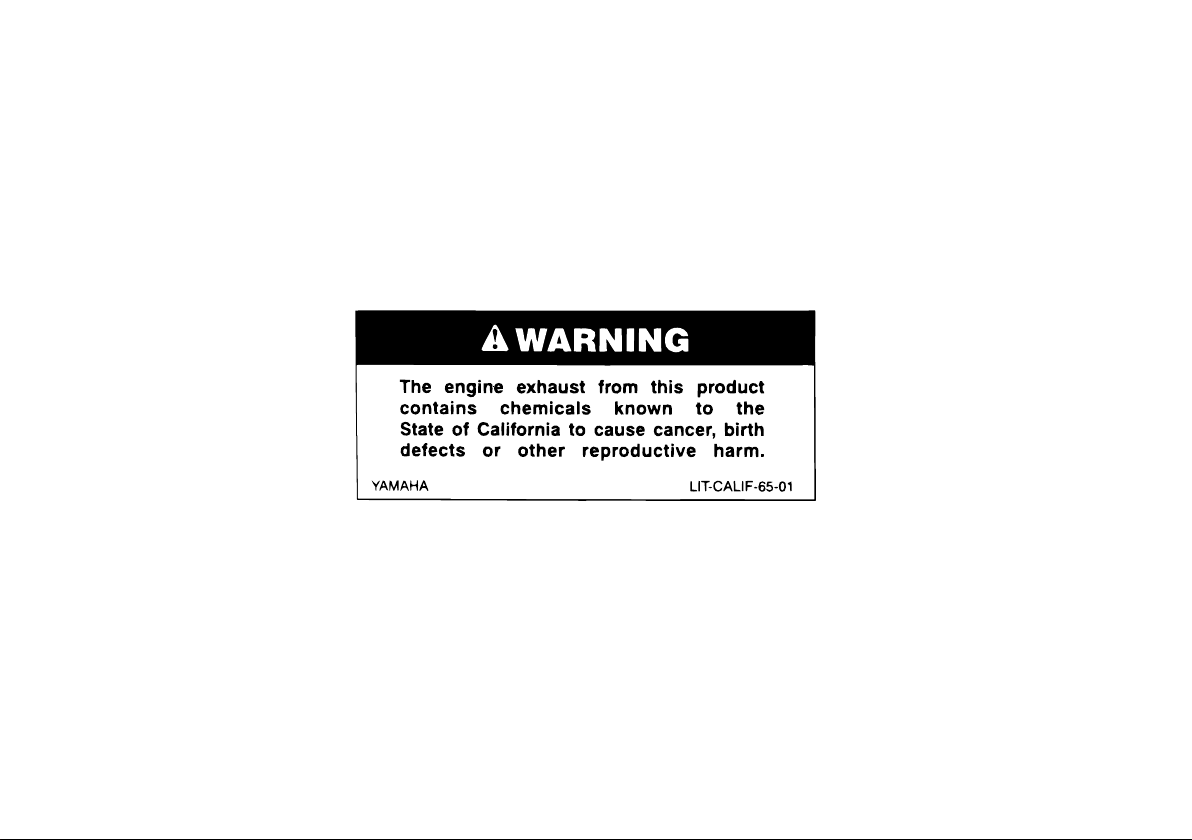
WARNING
THIS MACHINE IS DESIGNED AND MANUFACTURED FOR OFF-ROAD USE ONLY. IT IS ILLEGAL TO OPERATE
THIS MACHINE ON ANY PUBLIC STREET, ROAD OR HIGHWAY. SUCH USE IS PROHIBITED BY LAW. THIS MACHINE COMPLIES WITH ALMOST ALL STATE OFF-HIGHWAY NOISE LEVEL AND SPARK ARRESTER LAWS AND
REGULATIONS. PLEASE CHECK YOUR LOCAL RIDING LAWS AND REGULATIONS BEFORE OPERATING THIS
MACHINE.
IMPORTANT MANUAL INFORMATION
AFFIX DEALER
LABEL HERE
TTR250S
OWNER’S MANUAL
©2003 by Yamaha Motor Corporation, U.S.A.
1st edition, March 2003
All rights reserved.
Any reprinting or unauthorized use
without the written permission of
Yamaha Motor Corporation, U.S.A.
is expressly prohibited.
Printed in Japan.
P/N LIT-11626-17-01
EAU10191

TABLE OF CONTENTS
SAFETY INFORMATION ..............1-1
Location of important labels ......1-6
DESCRIPTION .............................2-1
Left view .....................................2-1
Right view...................................2-2
Controls and instruments ...........2-3
INSTRUMENT AND CONTROL
FUNCTIONS ................................3-1
Main switch ...............................3-1
Tripmeter ...................................3-1
Handlebar switches ...................3-1
Clutch lever ...............................3-2
Shift pedal .................................3-2
Brake lever ................................ 3-3
Brake pedal ............................... 3-3
Fuel tank cap .............................3-3
Fuel ...........................................3-4
Fuel tank breather hose ............3-5
Fuel cock ...................................3-5
Starter (choke) knob “1” ..........3-6
Seat ...........................................3-6
Adjusting the front fork ..............3-7
Adjusting the shock absorber
assembly .................................3-9
Starting circuit cut-off system .....3-11
PRE-OPERATION CHECKS .......4-1
Pre-operation check list ............4-1
OPERATION AND IMPORTANT
RIDING POINTS ........................... 5-1
Starting and warming up a
cold engine .............................. 5-1
Starting a warm engine .............5-2
Shifting ......................................5-2
Engine break-in ......................... 5-3
Parking ......................................5-4
PERIODIC MAINTENANCE AND
MINOR REPAIR............................ 6-1
Owner’s tool kit .........................6-1
Periodic maintenance and
lubrication chart ....................... 6-2
Removing and installing the
cowling and panels .................6-5
Checking the spark plug ...........6-6
Engine oil and oil filter
element ...................................6-7
Cleaning the air filter
element .................................6-10
Cleaning the spark arrester ..... 6-11
Adjusting the carburetor .......... 6-12
Adjusting the throttle cable
free play ................................ 6-13
Adjusting the valve
clearance .............................. 6-13
Tires ........................................ 6-13
Spoke wheels .......................... 6-15
Accessories and replacement
parts ...................................... 6-16
Adjusting the clutch lever
free play ................................ 6-16
Adjusting the brake lever
free play ................................ 6-17
Adjusting the brake pedal
position .................................. 6-18
Checking the front and rear
brake pads ............................ 6-18
Checking the brake fluid
level ....................................... 6-19
Changing the brake
fluid ....................................... 6-20
Drive chain slack ..................... 6-20
Lubricating the drive chain ...... 6-22
Checking and lubricating the
cables .................................... 6-23
Checking and lubricating the
throttle grip and cable ...........6-23
Checking and lubricating the
brake and clutch levers ......... 6-23
Lubricating the brake pedal ..... 6-24

TABLE OF CONTENTS
Checking and lubricating the
sidestand ...............................6-24
Checking the front fork ............ 6-24
Checking the steering .............6-25
Checking the wheel
bearings ................................6-26
Battery .....................................6-26
Replacing the fuse ..................6-27
Replacing the headlight bulb ...6-28
Replacing the taillight bulb ......6-29
Supporting the machine ..........6-30
Front wheel .............................6-30
Rear wheel .............................. 6-32
Troubleshooting ......................6-33
Troubleshooting chart .............6-34
MACHINE CARE AND
STORAGE.....................................7-1
Care ..........................................7-1
Storage ......................................7-3
SPECIFICATIONS .......................8-1
CONSUMER INFORMATION .......9-1
Identification numbers ............... 9-1
Motorcycle noise regulation ......9-3
Maintenance record ..................9-4
YAMAHA MOTOR
CORPORATION, U.S.A.
OFF-ROAD MOTORCYCLE
LIMITED WARRANTY ............ 9-5
YAMAHA EXTENDED
SERVICE (Y.E.S.) ................... 9-7

QQ
QQ
SAFETY INFORMATION
EAU10330
MACHINES ARE SINGLE TRACK VEHICLES. THEIR SAFE USE AND OPERATION ARE DEPENDENT UPON
THE USE OF PROPER RIDING
TECHNIQUES AS WELL AS THE EXPERTISE OF THE OPERATOR. EVERY OPERATOR SHOULD KNOW
THE FOLLOWING REQUIREMENTS
BEFORE RIDING THIS MACHINE.
HE OR SHE SHOULD:
●
OBTAIN THOROUGH INSTRUCTIONS FROM A COMPETENT
SOURCE ON ALL ASPECTS OF
MACHINE OPERATION.
●
OBSERVE THE WARNINGS
AND MAINTENANCE REQUIREMENTS IN THE OWNER’S MANUAL.
●
OBTAIN QUALIFIED TRAINING
IN SAFE AND PROPER RIDING
TECHNIQUES.
●
OBTAIN PROFESSIONAL TECHNICAL SERVICE AS INDICATED
BY THE OWNER’S MANUAL
AND/OR WHEN MADE NECESSARY BY MECHANICAL CONDI-
TIONS.
Safe riding
●
Always make pre-operation
checks. Careful checks may help
prevent an accident.
●
This machine is designed for
off-road use only, therefore, it is illegal to operate it on public streets,
roads, or highways. Off-road use
on public lands may be illegal.
Please check local regulations before riding.
●
This machine is designed to carry
the operator only. No passengers.
●
Many accidents involve inexperienced operators.
●
Make sure that you are qualified
and that you only lend your machine to other qualified operators.
●
Know your skills and limits.
Staying within your limits may
help you to avoid an accident.
●
Many accidents have been caused
by error of the machine operator. A
typical error made by the operator
is veering wide on a turn due to
EXCESSIVE SPEED or undercornering (insufficient lean angle for
the speed). Never travel faster
than warranted by conditions.
●
Ride cautiously in unfamiliar areas. You may encounter hidden
obstacles that could cause an accident.
●
The posture of the operator is important for proper control. The operator should keep both hands on
the handlebar and both feet on the
operator footrests during operation
to maintain control of the machine.
●
Never ride under the influence of
alcohol or other drugs.
Protective apparel
The majority of fatalities from machine
accidents are the result of head injuries. The use of a safety helmet is the
single most critical factor in the prevention or reduction of head injuries.
●
Always wear an approved helmet.
●
Wear a face shield or goggles.
Wind in your unprotected eyes
1
1-1

SAFETY INFORMATION
could contribute to an impairment
of vision that could delay seeing a
hazard.
●
1
The use of a jacket, heavy boots,
trousers, gloves, etc., is effective in
preventing or reducing abrasions
or lacerations.
●
Never wear loose-fitting clothes,
otherwise they could catch on the
control levers, footrests, or wheels
and cause injury or an accident.
●
Never touch the engine or exhaust
system during or after operation.
They become very hot and can
cause burns. Always wear protective clothing that covers your legs,
ankles, and feet.
Modifications
Modifications made to this machine not
approved by Yamaha, or the removal of
original equipment, may render the machine unsafe for use and may cause
severe personal injury. Modifications
may also make your machine illegal to
use.
Loading and accessories
Adding accessories or cargo to your
machine can adversely affect stability
and handling if the weight distribution of
the machine is changed. To avoid the
possibility of an accident, use extreme
caution when adding cargo or accessories to your machine. Use extra care
when riding a machine that has added
cargo or accessories. Here are some
general guidelines to follow if loading
cargo or adding accessories to your
machine:
Loading
The total weight of the operator, accessories and cargo must not exceed the
maximum load limit of 90.0 kg (198 lb).
When loading within this weight limit,
keep the following in mind:
●
Cargo and accessory weight
should be kept as low and close to
the machine as possible. Make
sure to distribute the weight as
evenly as possible on both sides of
the machine to minimize imbalance or instability.
●
Shifting weights can create a sudden imbalance. Make sure that accessories and cargo are securely
attached to the machine before
riding. Check accessory mounts
and cargo restraints frequently.
●
Never attach any large or heavy
items to the handlebar, front fork,
or front fender. These items, including such cargo as sleeping
bags, duffel bags, or tents, can
create unstable handling or a slow
steering response.
Accessories
Genuine Yamaha accessories have
been specifically designed for use on
this machine. Since Yamaha cannot
test all other accessories that may be
available, you must personally be responsible for the proper selection, installation and use of non-Yamaha
accessories. Use extreme caution
when selecting and installing any accessories.
Keep these guidelines in mind for
mounting accessories in addition to
1-2

SAFETY INFORMATION
those provided under “Loading”.
●
Never install accessories or carry
cargo that would impair the performance of your machine. Carefully
inspect the accessory before using
it to make sure that it does not in
any way reduce ground clearance
or cornering clearance, limit suspension travel, steering travel or
control operation, or obscure lights
or reflectors.
●
Accessories fitted to the handlebar or the front fork area can
create instability due to improper
weight distribution or aerodynamic changes. If accessories
are added to the handlebar or
front fork area, they must be as
lightweight as possible and
should be kept to a minimum.
●
Bulky or large accessories may
seriously affect the stability of
the machine due to aerodynamic effects. Wind may attempt to
lift the machine, or the machine
may become unstable in cross
winds.
●
Certain accessories can displace the operator from his or
her normal riding position. This
improper position limits the freedom of movement of the operator and may limit control ability,
therefore, such accessories are
not recommended.
●
Use caution when adding electrical accessories. If electrical accessories exceed the capacity of the
machine’s electrical system an
electric failure could result, which
could cause a dangerous loss of
lights or engine power.
Gasoline and exhaust gas
●
GASOLINE IS HIGHLY FLAMMABLE:
●
Always turn the engine off when
refueling.
●
Take care not to spill any gasoline on the engine or exhaust
pipe(s)/muffler(s) when refueling.
●
Never refuel while smoking or in
the vicinity of an open flame.
●
Never start the engine or let it run
for any length of time in a closed
area. The exhaust fumes are poisonous and may cause loss of
consciousness and death within a
short time. Always operate your
machine in an area that has adequate ventilation.
●
Always turn the engine off before
leaving the machine unattended
and remove the key from the main
switch. When parking the machine, note the following:
●
The engine and exhaust pipe(s)/
muffler(s) may be hot, therefore,
park the machine in a place
where pedestrians or children
are not likely to touch these hot
areas.
●
Do not park the machine on a
slope or soft ground, otherwise it
may fall over.
●
Do not park the machine near a
flammable source (e.g., a kerosene heater, or near an open
1
1-3

SAFETY INFORMATION
flame), otherwise it could catch
fire.
●
When transporting the machine in
1
another vehicle, make sure that it
is kept upright and that the fuel
cock(s) are turned to “ON” or
“RES” (for vacuum type)/“OFF”
(for manual type). If the machine
should lean over, gasoline may
leak out of the carburetor or fuel
tank.
●
If you should swallow any gasoline, inhale a lot of gasoline vapor,
or allow gasoline to get into your
eyes, see your doctor immediately. If any gasoline spills on your
skin or clothing, immediately wash
the affected area with soap and
water and change your clothes.
1-4

SAFETY INFORMATION
1
1-5
SAFETY INFORMATION
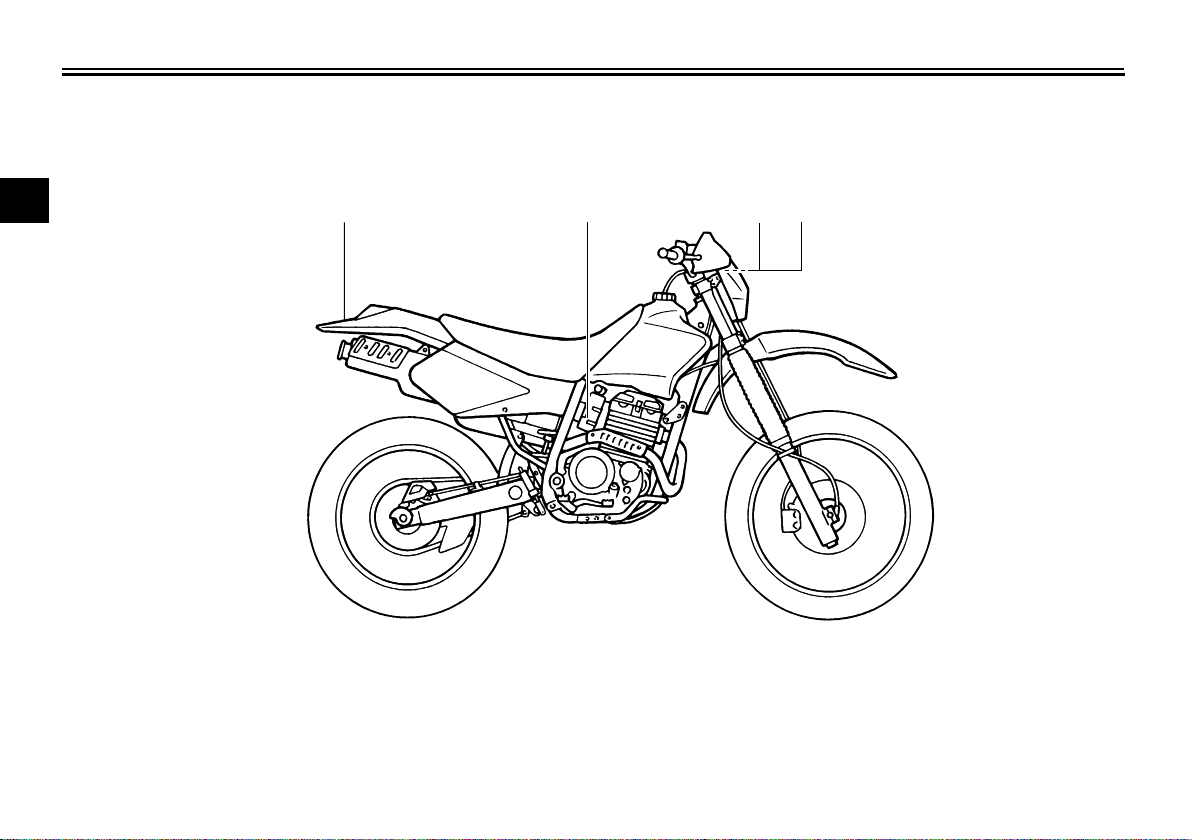
Location of important labels
Please read the following important labels carefully before operating this vehicle.
EAU10381
1
1
2
4
3
1-6
SAFETY INFORMATION
13
q
WARNING
Riding as a passenger can cause
the vehicle to go out of control.
Loss of control can cause a
collision or rollover, which can
result in severe injury or death.
NEVER ride as a passenger.
3XJ-2151H-A0
BEFORE YOU OPERATE THIS VEHICLE, READ
8
THE OWNER'S MANUAL AND ALL LABELS.
8
NEVER CARRY A PASSENGER. You increase
your risk of losing control if you carry a passenger.
NEVER OPERATE THIS VEHICLE ON PUBLIC
8
ROADS. You can collide with another vehicle if
you operate this vehicle on a public road.
ALWAYS WEAR AN APPROVED MOTORCYCLE
8
HELMET,eye protection, and protective clothing.
8
EXPERIENCED RIDER ONLY.
q
WARNING
5PA-2118K-00
24
q
WARNING
This unit contains high pressure nitrogen gas.
Mishandling can cause explosion.
Read owner's manual for instructions.
8
Do not incinerate, puncture or open.
8
YAMAHA
4AA-22259-80
TIRE INFORMATION
Cold tire normal pressure should be set as
follows.
FRONT :
100 kPa,{1.00 kgf/cm2}, 15 psi
:REAR
100 kPa,{1.00 kgf/cm2}, 15 psi
3RV-21668-A0
1
1-7
DESCRIPTION
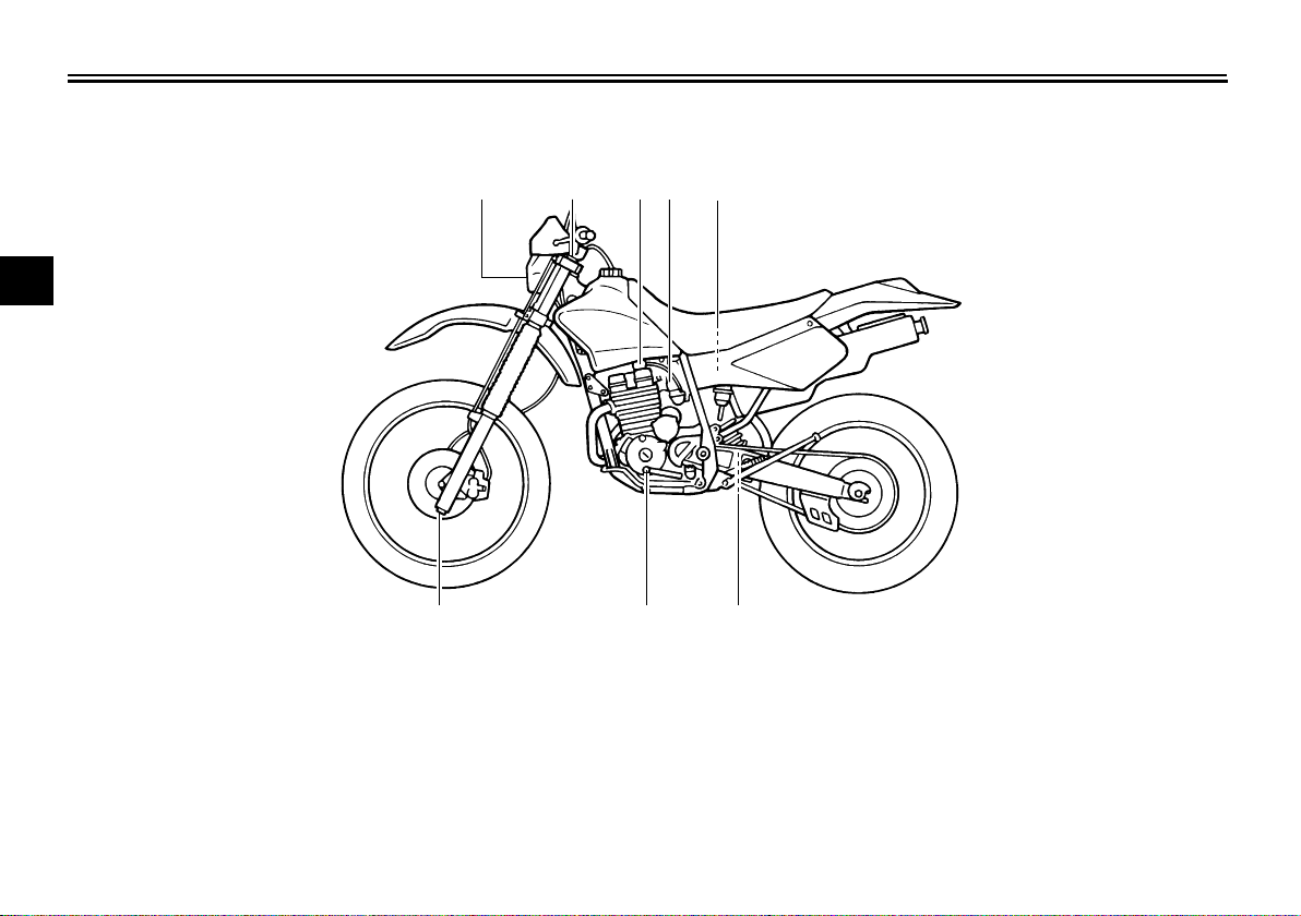
Left view
EAU10410
1
2
3
4
5
6
7
8
1. Headlight (page 6-28)
2. Front fork air valve (page 3-7)
3. Fuel cock (page 3-5)
9
4. Starter (choke) knob (page 3-6)
5. Air filter element (page 6-10)
6. Shock absorber assembly rebound damping force adjusting dial
(page 3-9)
7. Shift pedal (page 3-2)
1345
2
78
6
8. Front fork damping adjusting screw (page 3-7)
2-1
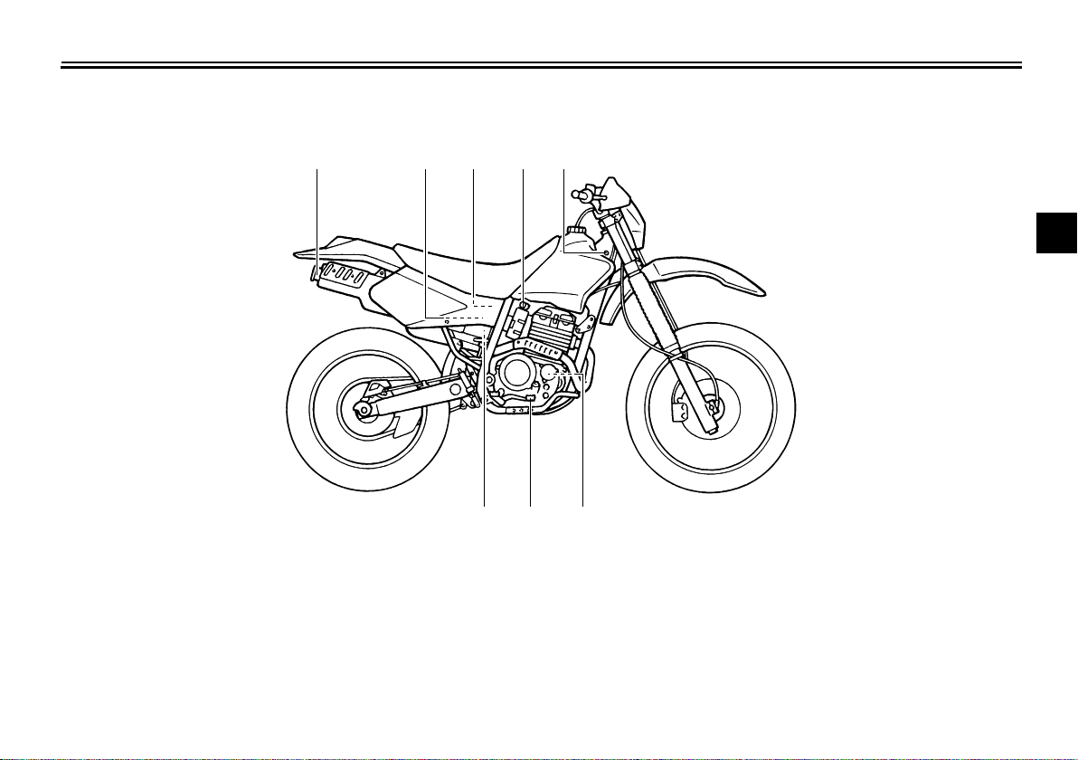
Right view
DESCRIPTION
EAU10420
12345
2
3
4
5
6
7
1. Spark arrester (page 6-11)
2. Battery (page 6-26)
3. Fuse (page 6-27)
4. Shock absorber assembly compression damping force adjusting
knob (page 3-9)
5. Main switch (page 3-1)
6. Engine oil filter element (page 6-7)
7. Brake pedal (page 3-3)
8
67
8. Shock absorber assembly spring preload adjusting nut (page 3-9)
8
9
2-2
DESCRIPTION
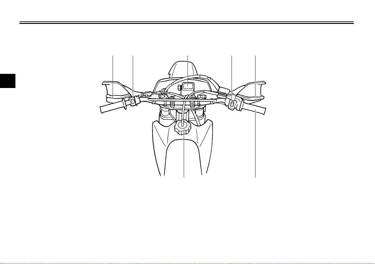
Controls and instruments
EAU10430
1
2
3
4
5
6
7
8
1. Clutch lever (page 3-2)
2. Left handlebar switch (page 3-1)
3. Tripmeter (page 3-1)
9
4. Right handlebar switches (page 3-1)
5. Brake lever (page 3-3)
6. Throttle grip (page 6-13)
7. Fuel tank cap (page 3-3)
1
2
34
7
5
6
2-3
1
1
2
INSTRUMENT AND CONTROL FUNCTIONS
EAU10450
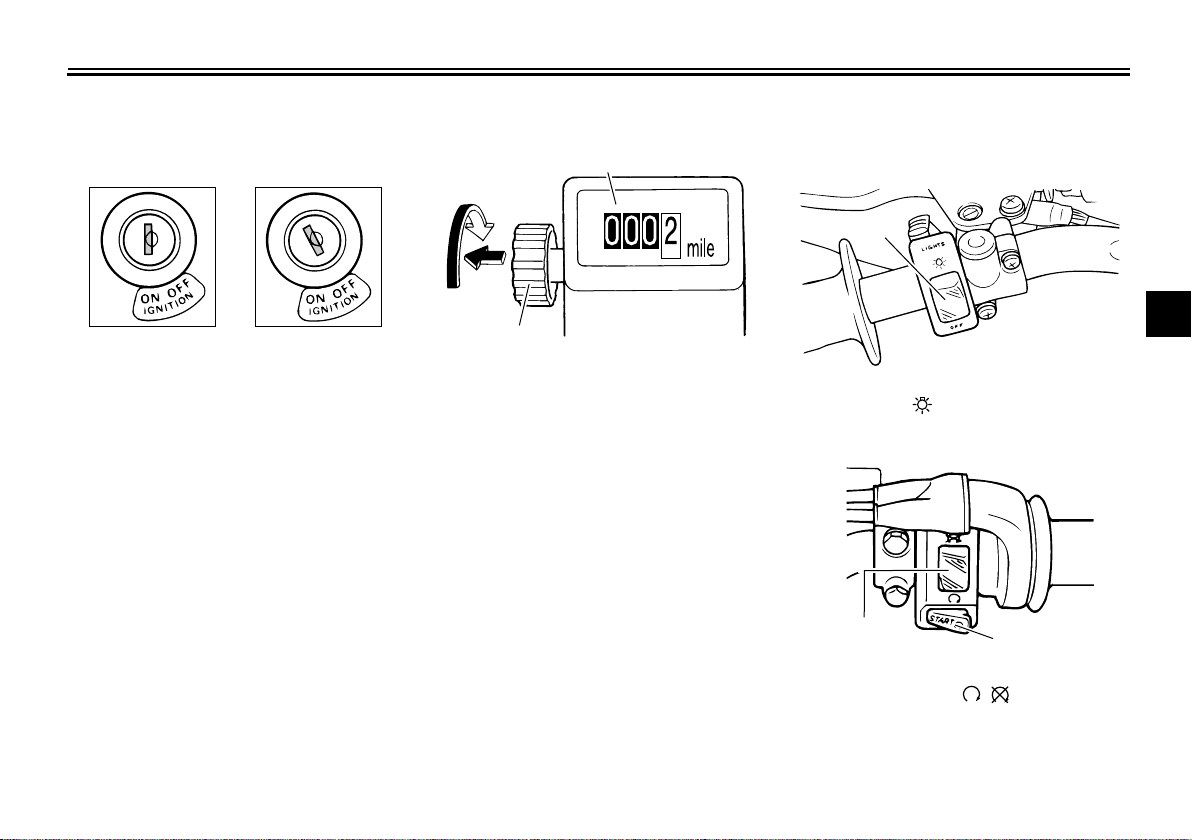
Main switch
ON
The main switch controls the ignition
and lighting systems. The various main
switch positions are described below.
ON
All electrical systems are supplied with
power, and the engine can be started.
The key cannot be removed.
OFF
All electrical systems are off. The key
can be removed.
OFF
EAU10630
EAU10660
EAU11830
Tripmeter
1
2
1. Tripmeter
2. Tripmeter reset knob
The tripmeter shows the distance traveled since it was last set to zero with the
reset knob. The tripmeter can be used
to estimate the distance that can be
traveled with a full tank of fuel. This information will enable you to plan future
fuel stops.
Handlebar switches
Left
1. Light switch “ ”
Right
EAU12341
2
3
4
5
6
7
8
9
3-1
1. Engine stop switch “ / ”
2. Start switch “START”
INSTRUMENT AND CONTROL FUNCTIONS
1
Light switch “ ”
Set this switch to “ ” to turn on the
headlight and the taillight.
1
CAUTION:
Always turn the key to “OFF” and
2
light switch to “OFF” when the engine is not running, otherwise the
3
headlight will stay on and the battery
may discharge due to extended use.
4
Engine stop switch “ / ”
5
Set this switch to “ ” before starting
the engine. Set this switch to “ ” to
stop the engine in case of an emergen-
6
cy, such as when the vehicle overturns
or when the throttle cable is stuck.
7
Start switch “START”
8
Push this switch to crank the engine
with the starter.
9
CAUTION:
See page 5-1 for starting instructions prior to starting the engine.
EAU12540
ECA10980
EAU12660
EAU12690
ECA10050
EAU31640
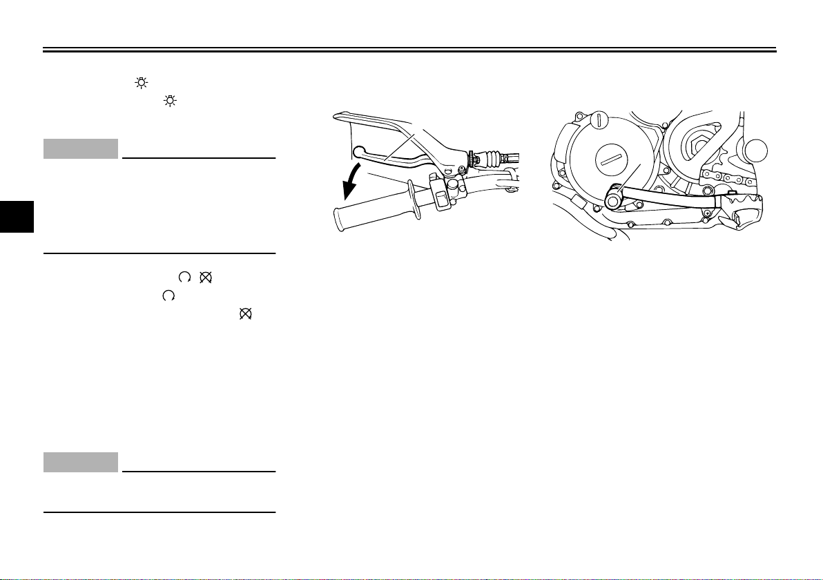
Clutch lever
1
1. Clutch lever
The clutch lever is located at the left
handlebar grip. To disengage the
clutch, pull the lever toward the handlebar grip. To engage the clutch, release
the lever. The lever should be pulled
rapidly and released slowly for smooth
clutch operation.
The clutch lever is equipped with a
clutch switch, which is part of the starting circuit cut-off system. (See
page 3-11.)
EAU12870
Shift pedal
1. Shift pedal
The shift pedal is located on the left
side of the engine and is used in combination with the clutch lever when
shifting the gears of the 6-speed constant-mesh transmission equipped on
this machine.
3-2
INSTRUMENT AND CONTROL FUNCTIONS
1
2
EAU12890
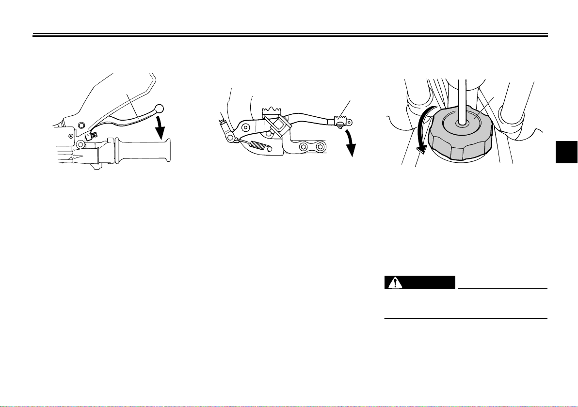
Brake lever
1
1. Brake lever
The brake lever is located at the right
handlebar grip. To apply the front
brake, pull the lever toward the handlebar grip.
EAU12940
Brake pedal
1
1. Brake pedal
The brake pedal is on the right side of
the machine. To apply the rear brake,
press down on the brake pedal.
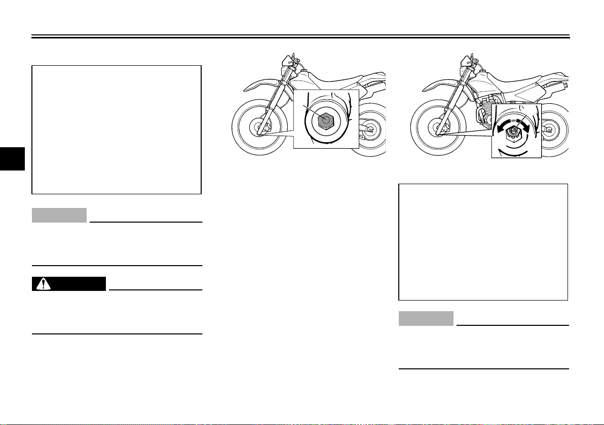
EAU13180
Fuel tank cap
1. Fuel tank cap
2. Remove.
To remove the fuel tank cap, turn it
counterclockwise, and then pull it off.
To install the fuel tank cap, insert it into
the tank opening, and then turn it clockwise.
EWA11090
WARNING
Make sure that the fuel tank cap is
properly closed before riding.
2
3
4
5
6
7
8
9
3-3
INSTRUMENT AND CONTROL FUNCTIONS
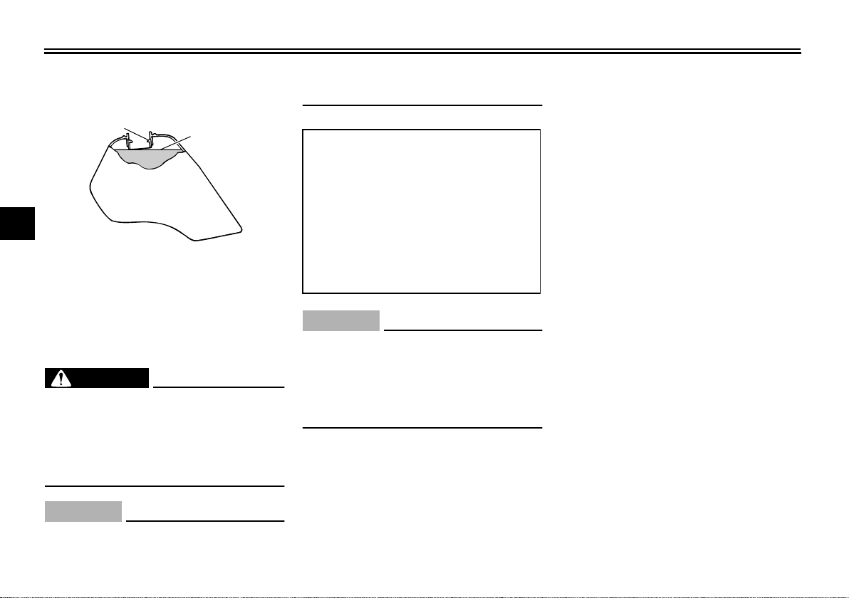
Fuel
1
1
2
3
4
1. Fuel tank filler tube
2. Fuel level
5
Make sure that there is sufficient fuel in
the tank. Fill the fuel tank to the bottom
6
of the filler tube as shown.
7
8
9
WARNING
Do not overfill the fuel tank, oth-
●
erwise it may overflow when the
fuel warms up and expands.
Avoid spilling fuel on the hot en-
●
gine.
CAUTION:
Immediately wipe off spilled fuel
with a clean, dry, soft cloth, since
2
EAU13210
EWA10880
ECA10070
fuel may deteriorate painted surfaces or plastic parts.
EAU13300
Recommended fuel:
UNLEADED GASOLINE
ONLY
Fuel tank capacity:
9.5 L (2.51 us.gal)
(2.09 imp.gal)
Fuel reserve amount:
2.0 L (0.53 us.gal)
(0.44 imp.gal)
ECA11400
CAUTION:
Use only unleaded gasoline. The use
of leaded gasoline will cause severe
damage to internal engine parts,
such as the valves and piston rings,
as well as to the exhaust system.
Your Yamaha engine has been designed to use regular unleaded gasoline with a pump octane number
[(R+M)/2] of 86 or higher, or a research
octane number of 91 or higher. If
knocking (or pinging) occurs, use a
3-4
gasoline of a different brand or premium unleaded fuel. Use of unleaded fuel
will extend spark plug life and reduce
maintenance costs.
Gasohol
●
There are two types of gasohol:
gasohol containing ethanol and
that containing methanol. Gasohol
containing ethanol can be used if
the ethanol content does not ex-
ceed 10%. Gasohol containing
methanol is not recommended by
Yamaha because it can cause
damage to the fuel system or vehi-
cle performance problems.
INSTRUMENT AND CONTROL FUNCTIONS
ON
FUEL
RES
OFF
1
ON
OFF
ON
FUEL
RES
1
RES
Fuel tank breather hose
1
1. Fuel tank breather hose
Before operating the machine:
●
Check the fuel tank breather hose
connection.
●
Check the fuel tank breather hose
for cracks or damage, and replace
it if damaged.
●
Make sure that the end of the fuel
tank breather hose is not blocked,
and clean it if necessary.
EAU13410
EAU13560
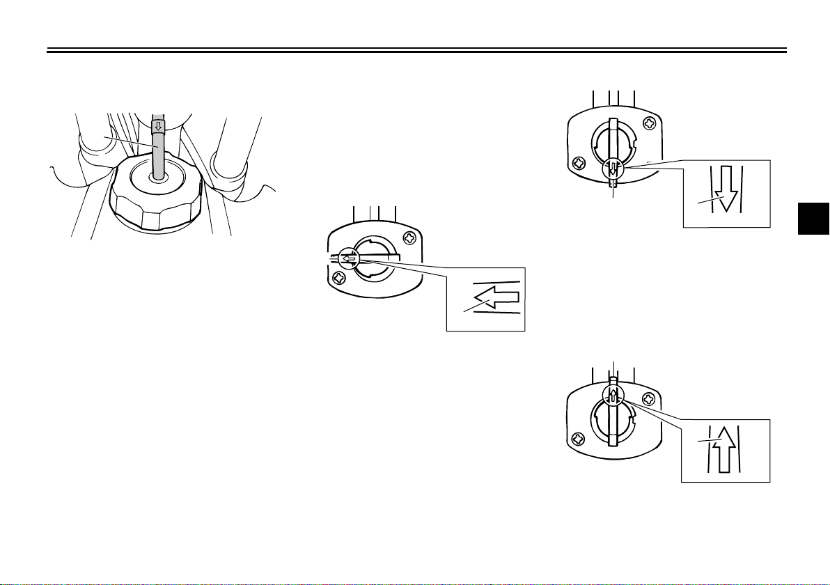
Fuel cock
The fuel cock supplies fuel from the
tank to the carburetor while filtering it also.
The fuel cock has three positions:
OFF
RES
OFF
FUEL
ON
1
1. Arrow mark positioned over “OFF”
With the lever in this position, fuel will
not flow. Always return the lever to this
position when the engine is not running.
3-5
ON
1. Arrow mark positioned over “ON”
With the lever in this position, fuel flows
to the carburetor. Normal riding is done
with the lever in this position.
RES
1. Arrow mark positioned over “RES”
This indicates reserve. If you run out of
2
3
4
5
6
7
8
9
INSTRUMENT AND CONTROL FUNCTIONS
1(×2)
fuel while riding, move the lever to this
position. Fill the tank at the first opportunity. Be sure to set the lever back to
“ON” after refueling!
1
2
3
4
5
6
7
8
9
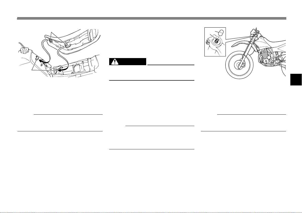
EAU13600
Starter (choke) knob “”
(b)
(a)
1
1. Starter (choke) knob “”
Starting a cold engine requires a richer
air-fuel mixture, which is supplied by
the starter (choke).
Move the knob in direction (a) to turn on
the starter (choke).
Move the knob in direction (b) to turn off
the starter (choke).
EAU13960
Seat
To remove the seat
Remove the bolts, and then pull the
seat off.
1. Bolt
To install the seat
1. Insert the projections on the front
of the seat into the seat holders as
shown.
3-6
INSTRUMENT AND CONTROL FUNCTIONS
1
2
1(×2)
2(×2)
1. Projection
2. Seat holder
2. Place the seat in the original position, and then tighten the bolts.
NOTE:
Make sure that the seat is properly secured before riding.
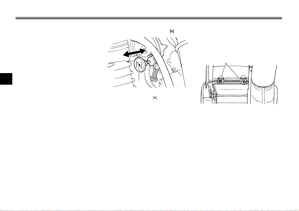
EAU14671
Adjusting the front fork
The front fork is equipped with air
valves for adjusting the spring rate and
screws for adjusting the damping force.
EWA10190
WARNING
There should be no difference in air
pressure between the fork legs.
Spring rate
The total spring rate is adjusted by
changing the air pressure as follows.
1. Lift the front wheel off the ground
according to the procedure on
page 6-30.
NOTE:
When checking and adjusting the air
pressure, there should be no weight on
the front end of the vehicle.
2. Remove the air valve cap from
each fork leg.
1. Front fork air valve cap
2. Front fork air valve
3. Check the air pressure in each fork
leg with an air pressure gauge.
NOTE:
An optional air pressure gauge is available at a Yamaha dealer.
4. To increase the spring rate and
thereby harden the suspension, increase the air pressure with an air
pump. To decrease the spring rate
and thereby soften the suspension, decrease the air pressure by
2
3
4
5
6
7
8
9
3-7
INSTRUMENT AND CONTROL FUNCTIONS
1
(a)
(b)
pushing each valve stem down.
Spring rate:
Minimum (soft):
1
2
3
4
5
Never exceed the maximum air pressure, otherwise the front fork oil
6
seals may become damaged.
7
Always adjust both fork legs equal-
8
ly, otherwise poor handling and loss
of stability may result.
9
Damping force
Air pressure = 0 kPa
(0 kgf/cm2, 0 psi)
Standard:
Air pressure = 0 kPa
(0 kgf/cm2, 0 psi)
Maximum (hard):
Air pressure = 40 kPa
(0.4 kgf/cm2, 5.8 psi)
ECA10090
CAUTION:
EWA10180
WARNING
5. Securely install the air valve caps.
1. Remove the rubber cap from each
fork leg.
1
1. Rubber cap
2. To increase the damping force and
thereby harden the damping, turn
the adjusting screw on each fork
leg in direction (a). To decrease
the damping force and thereby
soften the damping, turn the adjusting screw on each fork leg in direction (b).
1. Damping force adjusting screw
Damping setting:
Minimum (soft):
20 clicks in direction (b)*
Standard:
11 clicks in direction (b)*
Maximum (hard):
1 click in direction (b)*
* With the adjusting screw fully
turned in direction (a)
ECA10100
CAUTION:
Never attempt to turn an adjusting
mechanism beyond the maximum or
minimum settings.
3-8
 Loading...